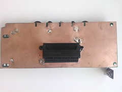
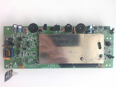
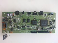
Lexis easter egg

The game Lexis published by Songbird has a really neat easter egg. You can play a game of Galaxian whenever you feel like it. Here’s how to access the easter egg:

Galaxian in Lexis6

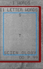
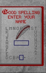
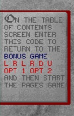
Go to the Table of Contents screen and press Left, Right, Left, Right, Up, Down, Option 1 and finally Option 2. After you have done that, start a regular game of Pages. It may seem that the game simply starts, but you get an easy finish, by completing the word “SCIENTOLOGY” with the missing T. Receive compliments and enter your name in the highscore table.

Galaxian in Lexis3 Galaxian in Lexis4 Galaxian in Lexis5

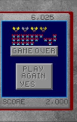
You should now have a game screen for a good game of Galaxian. A fine example of an easter egg that offers more gameplay.

Galaxian in Lexis Galaxian in Lexis2

Enjoy!

Posted in Games | Leave a comment

Programming tutorial: Part 16–Cartridges

Atari Lynx programming tutorial series:

In part 15 we discussed the memory and segments and how those are related. Before we can go into the details of loading segments into memory, we need some background on the cartridges that the Lynx uses for storage of binary information. This part we will look at the internals of cartridges and how to do raw reads from it.

Of ROM and RAM

Before we get started with the internals, it is worth pointing out a few pecularities of the Lynx. In previous parts we touched on this, but now a refresher and some details are badly needed.

You see, the Lynx only has RAM. 64 KB of it. Read part 12 and 15 to find out how this is organized. Other systems have less RAM (sometimes) and use part of their address space to look “into” ROM cartridges. These systems have the luxury of memory mapped swappable ROM. For example, the Atari VCS 2600 only has 128 bytes (!) of RAM, while there is around 4KB of address space to read from ROM “memory” of the inserted cartridge.

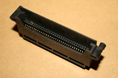
99 fgames were developed for the device. They were supplied as thin card-style cartridges with a prominent edge to make them easier to remove
Photo: Alex Kidman

No such luck for the Lynx. It only has RAM and will need to read its code and other binaries into RAM from the peripherial device called the cartridge. The cartridge can be viewed as a read-only harddisk of some sort. Like a PC the Lynx will have to read data from the cartridge and store it in memory.

A side note: at one point in time Atari had the idea to read games from tape. There is still reference of the tape and some hardware addresses like MAGRDY0 ($FD84) that are directly related. The timers 1, 3, 5 and 7 were also meant to be used for signalling the baud rate of the tape device.

It might seem that this is sort of limiting and that we took the short straw with the Lynx. Nothing is further from the truth. The setup allows us to use a lot of RAM in any way we like. We are not tied to certain memory ranges that we must use. Additionally, we can have cartridges that are much larger than the available RAM. The Atari Lynx cartridges come in different sizes. The common ones are 128, 256 or 512 KB, although smaller and larger variations can and do exist. We get to choose how and when to load data from the cartridge and where to store it. Heck, you can even stream live from the cartridge as some libraries have already demonstrated. HandyMusic can play sound effects in PCM format straight from the cartridge. How nifty is that?

Physical structure of the cartridge

Even though the sizes vary, all cartridges have something in common: they have the same (maximum) number of 256 blocks. For each cartridge every block contains a fixed number of bytes. Two simple formulas give the total cartridge size from the block size of a cartridge and vice versa:

TOTALSIZE = 256 * BLOCKSIZE             – or –
BLOCKSIZE = TOTALSIZE / 256

This tabel helps find the right sizes:

Cartridge size (KB) # Blocks Blocksize (bytes) Pins
64 256 256  A0-A7
128 256 512 A9-A8
256 256 1024 A0-A9
512 256 2048 A0-A10
1024 256 4096 A0-A10+?

The italic red ones indicate uncommon cartridges. No commercial cartridges with 64 KB and 1 MB have been released during the Atari age.

To give you a visual impression of the cartridges and their sizes, you can take a look at the picture below. It depicts the blocks and their sizes.

image

No matter how you look at the cartridges, their behavior is always that of a stream of bytes starting somewhere within the cartridge’s binary image and continuing for as long as you are reading bytes.

Close connections of console and cart

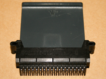
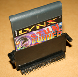
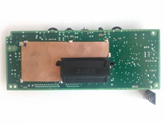
The Lynx and the inserted cartridge are connected to each other through a large flat connector that sits inside the Lynx console.

image image image
Pictures from http://www.flickr.com/photos/consolingmyself/sets/72157628031292511

The connector passes the pins to a couple of signals and pieces of electronics on the Lynx motherboard:

  1. VCC +5V
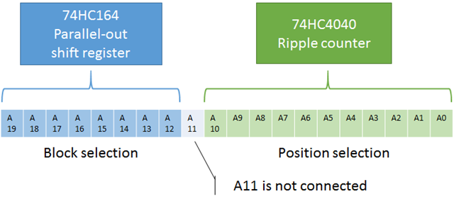
  2. 74HC4040 (12-stage binary ripple counter; generates cartridge addresses A0-A10)
  3. 74HC164 (8-bit serial-in, parallel-out shift register; generates cartridge addresses A12-A19)
  4. Data lines (8-bit lines that go on the data bus)
  5. Ground
  6. Auxiliary Data Input/Output (aka AUDIN, not to be confused with Audio IN)

As a programmer you must know about the ripple counter and the shift register. These two pieces of hardware together build the cartridge address you are reading the data from.

image

It works like this: the shift register builds the high part of the cartridge’s address. It can target 256 different values, that correspond to the 256 blocks (or pages) of the cartridge. The lower part of the address is created from the ripple counter. That counter will start counting at value 0 and auto-increment after every read from the cartridge.

Different sized cartridges have different wirings from the A0 to A20 lines. More precisely, smaller cartridges have not all pins from A0 to A10 connected. They will only wire from A0 up to whatever they need. A 64KB cartridge needs to be able to address 65536 bytes which requires 16 bits. It is sufficient to connect the wires A0 to A7.

image

Look back at the table above and find out what the pins for each cartridge size are.

The data lines that are present will hold the byte value from the cartridge. Reading it will pulse the CE0/ line on the cartridge, advancing bank 0 to the next byte in the ripple counter. And so on.

The AUDIN pin is used heavily on custom cartridges as follows:

  1. An extra address line for 1 MB cartridges, giving a virtual A20 line for large enough EEPROMS.
  2. A bank-switching bit that allows switching between more than one bank (two usually) to increase the maximum number of data in the cartridge to 1 MB as well.
  3. Enable bit for EEPROM carrying cartridges, such as Lynxman’s Flashcard. By setting this bit high and using special address lines, you can write to the EEPROM, effectively saving (limited amounts of) data to the cartridge. The EEPROM is a separate chip and has around 128-512 bytes of storage.

Shifting and rippling

The block and position selector need to be prepared to read the intended data from the cartridge. Each requires a different approach. The block selection is performed by bit-shifting the right block number into the shift register. The position within the block is prepared by performing strobes, which in turn requires dummy reading, so the ripple counter (automatically) increases to the right position in the block.

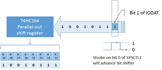
The shift register is like a conveyor belt of bits. You need to place a bit on the belt, advance the belt one position and place the next bit. After performing this 8 times you are certain to have the right block selected. There are two registers involved in performing this bit shifting: $FD8B (IODAT) and $FD87 (SYSCTL1).

image

IODAT is a hardware register that has a bit for the data to be placed into the shift register. Bit 1 of this address is the Cart Address Data output bit. IODAT is a weird register, in that it can be read from and written to, but the individual bits provide either input or output access, so will only make sense when used appropriately You can control what direction (input or output) it has by setting it in the IODIR ($FD8A) register. It is sort of similar to the way the MAPCTL register determines whether to use RAM or hardware registers based on the bits you set. You need to set the direction for bit 1 of IODAT to 1 for output. After that, by setting that same bit 1 of IODAT you determine what is the next bit on the shift register for the cartridge address. The shift register is advanced by strobing bit 0 (called CartAddressStrobe) of SYSCTL1. A strobe means that the value of the bit changes from 0 to 1 and back to zero again. Although the shifter will except the data at the rise of the strobe bit, it must be set back to 0, as the high level of the bit is used to reset the ripple counter.

Here’s the general flow:

  1. Turn on cartridge power
  2. Set directions on IODIR
  3. Set bit 1 of IODAT to value of current address part (in order from A19 to A12)
  4. Strobe bit 0 of SYSCTL1 (write 1 then 0, assuming you start with a zero value)
  5. Repeat from 3 until all 8 bits have been set.

In assembler code this looks like the following:

lynxblock:
	pha
	phx
	phy
	lda __iodat
	and #$fc
	tay
	ora #2
	tax
	lda _FileCurrBlock
	inc _FileCurrBlock
	sec
	bra @2
@0:	bcc @1
	stx IODAT
	clc
@1:	inx
	stx SYSCTL1
	dex
@2:	stx SYSCTL1
	rol
	sty IODAT
	bne @0
	lda __iodat
	sta IODAT
	stz _FileBlockByte
	lda #<($100-(>__BLOCKSIZE__))
	sta _FileBlockByte+1
	ply
	plx
	pla

The code above is from the CC65 implementation for selecting a block, actually. It shows a couple of things when we forget about the details and the optimizations.

  • Notice the two calls to SYSCTL1 for strobing bit 0 to advance the shift register.
  • The accumulator holds the block number to select. The rotation of the accumulator is moving the next (highest) bit in the carry flag. The first call to IODAT stores the value 1 in the CartAddressData bit, if that carry flag was set. The second call is used to always put a 0 in as the default, allowing the first call to be skipped for a zero bit.
  • At the end of the routine the remaing number of bytes in the block is set. We need this to determine the block edge transitions later on.
  • The __iodat value is used to get the current value of the IODAT register. Two shadow variables are declared to hold the values that where written to the registers IODAT and IODIR, conveniently called __iodat and __iodir (with double underscores). The shadow values are needed, because we can never read the values back from the registers, but might want to inspect them later on.

For completeness sake it is worth mentioning that in the startup code of any CC65 compiled program the IODAT and IODIR get initialized. They are set to $1B and $1A respectively. You can find the fragment for the shadow variables in crt0.s:

ldx     #$1b
stx     __iodat
dex;  $1A
stx     __iodir

The initialization of the actual registers IODAT and IODIR is done using a longer list of initialization values for Mikey. This is also in crt0.s (around line 40):

MikeyInitReg:  .byte $00, …, $50, $8a, $8b, $8c, $92, $93
MikeyInitData: .byte $9e, …, $ff, $1a, $1b, $04, $0d, $29

After having prepared the shift register it is a matter of reading data from the $FCB2 (RCART0) address. The $FCB3 (RCART1) address is used for reading from the second bank that might be present. Usually there is only one bank (bank0) on a cartridge. When reading from RCART0 the strobe CART0/ is used and it will advance the ripple counter to the next value, essentially autoincrementing the cart’s current address.

Reading from cartridges

Let’s assume that the data we want to read from the cartridge is located somewhere like this:

image

The picture shows the data starting in the middle of the second block and continuing into the fifthblock. The way to read this data is to advance the high part of the cart address to the second block, then dummy read until the starting point of the data is reached. A thing to remember is that the blocks have a certain size. This is relevant for two reasons.

  1. You need it in calculations of the desired block if all you have is the consecutive byte number. The ripple counter is automatically set to zero by changing the high part of the cartridge address (because this requires using the strobe for the bit shifter which resets the counter). This also means that you need to do the correct number of dummy reads, also determined by the blocksize.
  2. When crossing the boundary of a block you need to increase the block number to read the right data. If you do not do that, you will read data from the same block again. That’s why you need to keep track of how many bytes are left in the current block. When it reaches zero you must increase the block number by shifting in 8 bits again.

We could do this using assembler, but that has been done. There is also a higher level abstraction from C. The methods lseek and read will do what we want, …. sort of. This is what the functions look like (from the unistd.h include file):

int __fastcall__ read(int fd, void* buf, unsigned count);
off_t __fastcall__ lseek(int fd, off_t offset, int whence);

The lseek method takes three parameters, of which only one is relevant. The file descriptor fd is always 1 for the Lynx, and for whence only SEEK_SET is supported. That leaves the offset you want to have into the cartridge. The offset is passed using a type off_t, but it is in fact an long integer that can hold the large zero-based offset from the beginning of the cartridge. In a 2MB cartridge this might actually be 2^21-1 = 2097151.

lseek will set the shift register to the correct value and advance the ripple counter to the start of your data, both depending on your block size. It supports the 512, 1024 and 2048 byte block sizes.

off_t offset = 0;
lseek(1, offset, SEEK_SET);

You might need to calculate the offset from the block number and offset in the block. That’s kind of silly, because the lseek implementation does the reverse. It’s just the way lseek is defined.

You need to include the headers stdio.h (for SEEK_SET constant), unistd.h (for the function prototypes of lseek and read) and sys\types.h (for the off_t type).

The actual reading is performed by calling read.

unsigned char buffer[256];
read(1, &buffer, 256);

You need to have a buffer that is going to hold the data read from the cartridge. The example above shows a 256 byte buffer and reads a 256 bytes sized chunk from the cartridge into it.

Here is an example of how to read the contents of your cartridge and dump it to the screen in multiple pages:

void dump_cartridge()
{
  off_t offset = 0;
  unsigned char buffer[80];
  unsigned char byte;
  char text[4];
  unsigned char page = 0, index = 0, x = 0, y = 0;


// Advance current address to start of cartridge lseek(1, offset, SEEK_SET); do { // Read 80 bytes for one page into buffer read(1, &buffer, 80); index = 0; tgi_clear(); // Draw all values for (y = 0; y < 10; y++) { for (x = 0; x < 8; x++) { itoa(buffer[index++], text, 16); tgi_outtextxy(x * 20, y * 10, text); } } tgi_updatedisplay(); wait_joystick(); } while (++page < 3); }

This example uses a loop that will read 80 bytes for a page into the buffer, then display them in hexadecimal value 8 byte per line for a total of 10 lines. Pressing any normal button on the Lynx advances the current page.

image

You should try this: open the LNX file using the Binary Editor (right-click your tutorial-cartridge.lnx file, then select Open With…) and compare the contents you see with what is displayed. Mind you, you have to skip 64 bytes of the LNX files. We’ll explain later why that is.

The example is included in the sample source code. It can easily be expanded to allow you to select the current block number and start from there.

Next time

This part showed how the cartridge system works at a low level and with the CC65 methods lseek and read. The Lynx cartridge can also use a simple file system with a directory and file entries. The next part will we look at how files can be read, and how this relates to the segments we saw in memory segments. Till then.

Posted in Tutorial | 5 Comments

Programming tutorial: Part 15–Memory and segments

Atari Lynx programming tutorial series:

In part 12 we covered memory in the Lynx for the first time. By now you may have run into memory limitations while building your Lynx games. Admitted, 64KB of RAM is not really much, especially considering that considerable amounts of the memory are required for the Lynx hardware.

Atari Lynx memory layout

The layout of the Lynx’s memory varies over time. At startup, there is nothing really loaded and the memory layout resembles this:


The green areas that are required by the hardware meaning both Suzy and Mikey. The Mikey 65SC02 requires zero page memory and a stack at $0000 and $0100 respectively. It’s yours to use, but only through zero page addressing and variables, plus by Push and Pull instructions that manipulate the stack. You cannot use these 512 bytes for any other purpose. This is the main reason that most programs get loaded at $0200, which is exactly after the stack’s memory. We already saw that $FC00 to $FCFF contains memory mapped registers for Suzy, and $FD00 to $FDFF likewise for Mikey. $FE00 to $FFF7 is the boot ROM area that is used for booting the Lynx.

After initialization of the Lynx hardware and the C and TGI libraries from the CC65 toolset the memory looks like this:


As you can see in orange, there are three new memory areas:

  • C stack
    The C library uses a stack of its own. This stack is usually 2KB large and is needed for more complex pieces of code (e.g. recursive functions).
  • Video buffers
    The TGI library initializes the video driver and will automatically allocate two buffer for video and do double buffering to avoid screen tearing and other weird effects during updates. One buffer requires 160*102 = 16320 pixels. Since each pixel can hold 16 colors and requires only 4 bits to hold the pen index, the actual number of bytes is 8160 (or $1FE0 in hex). With two required buffers, that’s quite a lot of memory.

Excessive direct access

One thing may have struck you as odd: how come we can use the area from $FC00 to $FDFF where Suzy and Mikey’s hardware mapped registers are. Wouldn’t there be a conflict between the registers and the RAM address space? Would we have to do a lot of memory mapping tricks to make it work? Luckily, we do not have to reserve that area and no mapping of the memory is required. That would be way too complicated. No, the good thing is that the LCD panel gets its data directly from RAM memory… always. This feature is called DMA for Direct Memory Access. So, the video display will always read RAM, no matter where the video buffers are located.


That’s why it is better to overlay it on top of an area that is otherwise less (easily) useable. Hence, the Suzy and Mikey address spaces. We can simply leave it at the regular hardware space, so we can access the special registers. The RAM access is not needed, unless we want to draw directly into the video buffers. That is pretty unlikely.

The same will hold true for the collision buffer, should you want to use that. It will take another 8160 bytes and can be located anywhere. You probably want to lay it right before the first video buffer. That’s where TGI will place it if you use the tgi_setcollisionbuffer(1); call.

With the C-stack and the video buffers in place you are around 18 KB poorer in memory, 26 KB for a collision buffer as well. The bottom line is that in most cases (no collision detection) you can spend your memory from $0200 to $0B838.

Configure my memory

Let’s take a look at how this translates to the CC65 suite. The programs and games we write consist of C and assembler code. The cc65.exe compiles the C code and generates assembler code from it. The assembler code (from C and your own) gets assembled by ca65.exe. We end up with a couple of object modules that need to be tied together by the linker. The object modules do not have exact addresses for memory just yet. It uses placeholders to be flexible in the actual allocation in memory. The linker ld65.exe performs the connection of the modules and the choice of final memory locations based on the configuration of your memory areas as indicated in a configuration file.

Each specific area in memory has a few characteristics:

  • Start address
    The area is located from a specific address up in memory space. As an example, take the video buffer that has its start address at $C038.
  • Area size
    Each area is of a particular size. Sticking with the same example, the video buffers are both 8160 bytes in size.
  • Type of memory
    Some memory areas are read or write or read/write. In the Lynx we mostly deal with read/write memory, because everything memory is located in the 64KB of RAM. Other systems have memory mapped cartridges that are ROM, i.e. read-only.

The linker uses configuration files to tie the individual parts of your program or game together. A configuration file holds information on the memory area and segments. The ld65 linker has built-in configurations for each of the known targets. The lynx has 4 built-in configurations:

  1. lynx
    The default configuration that will have the MEMORY section like above. It adds a small boot loader and a required directory, plus a LNX header so it can run in Handy. The ROM image without the LNX header can be burned to an EEPROM or Flashcard and will produce a working cartridge.
  2. lynx-bll
    This configuration creates a BLL header to the output file, so it can be uploaded via a PC to ComLynx cable using any of the cartridges that allow BLL uploads (e.g. SIMIS and Championship Rally).
  3. lynx-coll
    Essentially the same configuration as the default one. It claims an additional $1FE0 of memory for the collision buffer, before the first video buffer.
  4. lynx-uploader
    This configuration adds a special uploader area right before the first video buffer. The useable RAM area is reduced by a full $100 (supposedly because of alignment?). I believe this configuration file does not function correctly.

Shown below is a fragment of the default configuration that is used by the linker ld65.exe for the lynx target in case you did not specify your own configuration.

MEMORY {
  ZP:     file = “”, define = yes, start = $0000, size = $0100;
  HEADER: file = %O,               start = $0000, size = $0040;
  BOOT:   file = %O, start = $0200, size = __STARTOFDIRECTORY__;
  DIR:    file = %O,               start = $0000, size = 8;
  RAM:    file = %O, define = yes, start = $0200,
          size = $BE38 – __STACKSIZE__;
}

You can see what a particular configuration is by running:

ld65.exe –dump-config lynx

where the bold item is the configuration name. The source file for the default lynx configuration is called lynx.cfg. You can find it in your CC65 folder under the source code for ld65, presumably C:\Program Files\CC65\src\ld65\cfg. This configuration is compiled as part of ld65.exe, so changing the file has no effect. The other three configuration files are located in the same folder.

Focus on the bold items in the MEMORY section for now. You should be able to recognize some of the numbers. Zero page (ZP) runs from $0000 to $00FF, for a total size of $0100. The user available RAM area starts at $0200 as we saw earlier and runs until $B837. The size is computed as follows:

VIDEOBUFFER1_START – STACKSIZE – RAM_START
= $C038-$0200-STACKSIZE = $BE38 – $0800 = $B638 (46648 bytes)

The default configuration file does not give you the origin of the numbers, just the correct (resulting) ones. The constants come from the symbols section of the same configuration file:

SYMBOLS {
  __STACKSIZE__: type = weak, value = $0800; # 2k stack
  __STARTOFDIRECTORY__: type = weak, value = $00CB;
  __BLOCKSIZE__: type = weak, value = 1024; # cart block size
  __EXEHDR__:    type = import;
  __BOOTLDR__:   type = import;
  __DEFDIR__:    type = import;
}

The stack size and start of directory are defined constants in the symbols section. These values can be used to define your memory areas and make them more flexible and less hardcoded. You could change the C stack size and make it bigger or smaller for your needs. All it takes is adjusting the value attribute of the __STACKSIZE__ symbol.

There are a couple of things in the memory and symbols section that do not make sense right now. We will get to them in time. For now, suffice to say that HEADER, BOOT and DIR are areas for respectively the Handy emulator’s LNX file header, the encrypted boot loader on the cartridge and the directory with file entries on the cartridge.

Define it for me

Notice how some of the memory areas use an attribute called define with a value of yes and no. Each memory area that has a define=yes will make the linker emit two values. For an area called AREA51 it will emit __AREA51_START__ and __AREA51_SIZE__ corresponding to the start address and size of the memory.

Other pieces of code may rely on these values to allow for a flexible layout of memory and the code that is tied to the memory layout. An example is the implementation of the C stack that depends on the location and size of the RAM memory area. We already saw that the __STACKSIZE__ is a constant in the symbols. But the implementation also relies on the final physical location. It uses the value of __RAM_START__ to indicate the start address. Later, the linker will emit this value because a memory area called RAM is defined. When linking together, all puzzle pieces fit together.

In a while you will see how the linker emitted values for these defines on memory areas can be very useful. For one, they allow you to create the file entries in the directory structure that each larger game cartridge will have.

Dividing in segments

The source code items you create get compiled, assembled and assigned to the memory areas. There’s another dimension to all this. The source code consists of elements such as executable code, variables and static data, that have a different behavior and memory requirements. Similar elements are combined and group together into memory segments of a certain type. In general this allows for the protection of memory and programs residing in it. There are four segment types in C source code:

  1. Code
    Regular executable code. Normally, this cannot be altered and it resides in a read-only memory segment. If code is self-modifying it cannot reside in this segment.
  2. Data
    Refers to data that can be altered. This data comes from the global and static variables that you declare and initialize with values. These values are combined in the data segment. They can be found in the object module as binary values that get copied by the loader at the memory location of the variables, initializing them to the values you gave them. After that they can be altered, because the memory is for variables (after all).
  3. Read-only data
    Data, but this is not meant to be altered. It is reference data from constant valued variables (marked as const). Some examples of read-only data are binary data for images and music, and text strings containing messages.
  4. Bss (Block Start by Symbol)
    This is data that is uninitialized. It will have a zero or null value. There is no need for the object module to contain this data, just the location in memory. A simple routine can initialize the values, because it will be zero anyway.

That’s a lot of theory, so a real example with code might illustrate this a bit. Take the following code sample:

unsigned char a;
char b = 42;
const char text[] = “Hello, World!”;

void example()
{
  int x, y = 1337;
}

The compiler will generate the following assembler code for this (showing relevant fragments):

.segment    “DATA”
_b :
  .byte  $2A

.segment    “RODATA”
_text :
  .byte  $48, $65, $6C, $6C, $6F, $2C, $20, $57, $6F, $72, $6C, $64, $21, $00

.segment    “BSS”
_a : .res    1, $00

; ———————————————————– –
; void __near__ example(void)
; ———————————————————– –

.segment    “CODE”
.proc    _example : near

.segment    “BSS”
L0035 :
  .res    2, $00
L0036 :
  .res    2, $00

.segment    “CODE”
;
; int x, y = 1337;
;
  ldx     #$05
  lda     #$39
  sta     L0036
  stx     L0036 + 1
;
; }
;
  rts

.endproc

Hopefully you can make some sense of the transition from C to 6502 assembler. Notice how the segments for the various types of code and variables is declared. It uses the .segment keyword combined with the quoted segment name. Since b was initialized it is placed in the data segment with its initialization value. Likewise, a was not initialized and can reside in the bss segment. The constant value for text is listed as the hex ASCII values in the read-only data segment. The code segment is used for the implementation of example.

What may come as a surprise is that the initializer for y inside the example function is placed in the bss segment just like x. The reason is that y needs to be initialized every call to example(), so it is not sufficient to have the value 1337 in the data segment. Instead it is placed in the method itself and y is simply placed in bss, to save size in the binary image for the object module.

Choosing your segments

The names for the segments we just saw might seem arbitrary, but nothing is further from the truth. You chose them when you compiled your C source code. You don’t remember? Well, that’s because we never really discussed this. I will take you back to one of the first tutorials where we looked at the MAKE files for our projects. Here’s an excerpt from the lynxcc65.mak file:

CODE_SEGMENT=CODE
DATA_SEGMENT=DATA
RODATA_SEGMENT=RODATA
BSS_SEGMENT=BSS

SEGMENTS=–code-name $(CODE_SEGMENT) \
  –rodata-name $(RODATA_SEGMENT) \
  –bss-name $(BSS_SEGMENT) \
  –data-name $(DATA_SEGMENT)

# Rule for making a *.o file out of a *.c file
.c.o:
  $(CC) -o $(*).s $(SEGMENTS) $(CFLAGS) $<
  $(AS) -o $@ $(AFLAGS) $(*).s

The MAKE file defined some macros for the 4 segments and gave them the names of CODE, DATA, RODATA and BSS. It might have been anything you liked, although changing this will force some adjustments in other places as well. The inference rule for .o files for object modules from C source code shows that the cc65.exe compiler takes the arguments –code-name, –rodata-name, –bss-name and –data-name to define the segments names used in the compilation to assembler code. This will make the compiler emit the .segment “DATA” and similar pieces of assembler code we saw in the earlier fragment.

Every time you call the compiler cc65 you are free to pass different segment names. This allows you to choose your segment names for all C files that are compiled by that single command. As the SEGMENTS macro is like a global variable and the inference rule will apply to all times the rule is triggered, it is a bit fairer to say that it applies to every C file that is affected by your make file and thus your entire project as it currently is organized.

If you want a more fine grained control over the segments you have a few options:

1. Create more MAKE files

Each MAKE file will hold its own SEGMENTS redefinition. The lynxcc65.mak file is included by every MAKE file, and defines the SEGMENTS macro first. If you add your own (re)definition in your MAKE file (say fonts.mak), it will overrule the previous definition with your new one. A separate MAKE file can be triggered by calling:

cd fonts && $(MAKE) $* /f fonts.mak

assuming you have placed the items build by the fonts.mak MAKE file into a relative subfolder fonts.
The fonts.mak file should hold a new definition like this:

SEGMENTS=–code-name FONTS_CODE \
  –rodata-name FONTS_RODATA \
  —bss-name FONTS_BSS \
  —data-name FONTS_DATA

2. Include #pragma statements in your C source code

The cc65.exe compiler recognizes the following #pragma statements: Adding this at the top of your C file will make sure that all code inside that C file is compiled into the specified segment names. It could be used midway through the code, but that would mean that some code gets compiled into the default SEGMENTS defined segment names, and the rest in the #pragma ones.

#pragma data-name (“FONTS_DATA”)
#pragma rodata-name (“FONTS_RODATA”)
#pragma code-name (“FONTS_CODE”)
#pragma bss-name (“FONTS_BSS”)

It is even possible to push the current (old) name for a segment onto a sort of stack with the push keyword. It seems unlikely that you will need this control any time soon.

So far we discussed how you can control the segments for C code. In case you are writing assembler code yourself, you will need to specify the segments for the various types of code and variables yourself. You will use the .segment keyword, just like in the compiler generated assembler code, to do so. As a matter of fact, you were already using it without knowing it.

# Rule fore making a *.o file out of a *.bmp file
.bmp.o:
  $(SPRPCK) -t6 -p2 $<
  $(ECHO).global _$(*B) > $*.s
  $(ECHO).segment “$(RODATA_SEGMENT)” >> $*.s
  $(ECHO) _$(*B) : .incbin “$*.spr” >> $*.s
  $(AS) -t lynx -o $@ $(AFLAGS) $*.s
  $(RM) $*.s
  $(RM) $*.pal
  $(RM) $*.spr

When a bitmap file was used to create the read-only SCB data for a sprite, it used an inference rule that generates a new assembler file containing the line

.segment “RODATA”

or whatever the read-only data segment is called by the RODATA_SEGMENT macro at that point in time. For example, when we did the robots.bmp file this gave the following robots.s assembler file:

.global _robot
.segment “RODATA”
_robot:
  .incbin “robot.spr”

It might require a different inference rule or redefinition of RODATA_SEGMENT to place your sprite data in an other segment.

Segments and areas

At this point you are probably wondering what all these segments and memory areas are all about. And maybe even how the two are related like I hinted at when I mentioned another dimension to memory. Get ready for it, here it comes.

Individual segments are assigned to a memory area. As memory areas can hold various types of memory, like read/write for RAM or read-only for ROM, certain segments should go into compatible memory areas. E.g., code segments can come from ROM, but data should always be assigned to RAM, as it requires read/write memory.

Typically (for the Lynx) related segments are assigned to the same memory area. The Lynx only has RAM memory to work with. Admitted, the cartridges are like ROM, but it is accessed as a sequential stream that needs to be copied into RAM before it can be used.

The linker can work its magic for each of the segments that are assigned to memory areas. It can allow segments to be assigned to overlapping memory areas. This way we can have code and data in the same memory space at different times. By loading the required code and data at the appropriate time it will enable us to fit more code into our already constrained memory space.

The linker configuration file has a section for the segments and their mapping to memory areas. It tells the linker what type of code or data is in each segment and where to load the segment into memory. Here is a fragment from the default lynx configuration:

SEGMENTS {
  EXEHDR: load = HEADER, type = ro;
  BOOTLDR: load = BOOT, type = ro;
  DIRECTORY:load = DIR, type = ro;
  STARTUP: load = RAM, type = ro, define = yes;
  LOWCODE: load = RAM, type = ro, optional = yes;
  INIT: load = RAM, type = ro, define = yes, optional = yes;
  CODE: load = RAM, type = ro, define = yes;
  RODATA: load = RAM, type = ro, define = yes;
  DATA: load = RAM, type = rw, define = yes;
  BSS: load = RAM, type = bss, define = yes;
  ZEROPAGE: load = ZP, type = zp;

  EXTZP: load = ZP, type = zp, optional = yes;
  APPZP: load = ZP, type = zp, optional = yes;
}

The bolded items are the segments we have encountered so far. CODE and RODATA are read-only segments as indicated by the type=ro attribute. DATA is read-write and BSS is of type bss, like you would expect. Each of these segments gets loaded into the RAM memory area. That much makes sense, as the RAM segment is currently the only user memory,

There are a few other segments (ZEROPAGE, EXTZP, APPZP) defined that are used by the compiler for zero page variables. The segments at the top EXEHDR, BOOTLDR and DIRECTORY are for creating a binary image that you can run in Handy. The STARTUP, LOWCODE and INIT segments are for the C runtime to put stuff that needs to be in potentially special areas. Consider these a given for now.

Also, notice the fact that some segments are marked as optional, where others have the define=yes attribute. The former means that the segment might not actually be there and some optimizations can be done. The latter will make the linker emit values for the section, similar to what it does for define=yes in memory areas. For a segment named FONTS_DATA the linker creates values __FONTS_DATA_SIZE__ and for FONTS_CODE two values __FONTS_CODE_LOAD__ and __FONTS_CODE_SIZE__. The values will come in useful at a later time.

Some rules of engagement

You might think about renaming some of the areas and segments. Be careful though, because some things simply need to be present and named according to presets. As an example, the C runtime library depends on the RAM memory area to be present. It assumes that the C stack is located directly after the RAM area. It uses the generated values for __RAM_START__ and __RAM_SIZE__.

Next time

This was a pretty deep and theoretical part in the tutorial. It covered a lot of ground that was more computer science related and less specific for the Lynx. Nevertheless, it was necessary to tackle this, because a lot of other Lynx and CC65 specifics are related to it either directly or indirectly. Next time we will continue our investigation of segments and look into loading code and data into memory from cartridges. Till then.

Posted in Tutorial | Leave a comment

Programming tutorial: Part 14–Timers

Atari Lynx programming tutorial series:

In the last part of the tutorial we looked at how the Lynx console uses UART and how the hardware behaves. Before we dig deeper into ComLynx and programming for it, we need to take a little detour to investigate timers. In this part we will cover the basics of timers, the hardware, how they work and get you started programming the timers.

Lynx and timers

The Atari Lynx has a customized 65SC02 processor called Mikey. One of the customizations is the addition of a set of timers. The Lynx has 12 timers inside of Mikey: 8 of these are “normal” timers and the other four are audio channels, which behave like timers but generate audio. We will look at the 8 regular timers first and are going to cover audio and channels in a later tutorial part.

First, what are the timers in the Lynx? There are a number of possible meanings to the word timer. The Lynx has countdown-timers, meaning they count down to zero. They have some characteristics and specific behavior.

The short story on timers

An activated timer counts down from a start value to zero at a specific pace. Once it reaches zero it will underflow and optionally cause an interrupt (IRQ) with the timer’s flag set in the interrupt status byte (available through INTSET or INTRST). Also, it might reload to counter to a backup value and continue counting down again.

And the long story with pretty pictures

A timer ticks down to zero at a certain frequency. It does so by reducing its counter value at the end of every time interval. That interval is called the source period. The timer keeps its current value for the length of the interval, before dropping by –1 (minus 1) at the end.

image

When the timer has reached zero, it is said to “expire” or “timeout”. It will expire at the end of the period. This means that when a timer starts counting down from 5, it will expire after 6 (not 5) periods of time. An expiring timer might trigger an IRQ and might reload. Both of these depend on the settings of the timer.

If a timer has reloading enabled, the value of the timer will change to the backup value (aka reload value) of the timer after it expires. The behavior of a reloading timer would look like this:

image

Note that the start value of a timer does not have to be the same as the reload value, as depictured above. I intentionally had it start at 3, instead of the reload value 5.

The timers all behave the same, with only a very small number of exceptions and special purposes for some of them. They share the following properties:

  • Count enable
    A timer can be turned on (enabled) or off (disabled). Only when it is enabled will it count down.
  • Source period
    The timer counts down one tick at a time. One tick takes an amount of time that is called the “source period”. The source period ranges from 1, 2, 4, 8, 16, 32 to 64 µs (microseconds).
  • Current count
    The timer has a current value or count that indicates how many periods are left for the timer to reach zero.
  • Reload enable
    When the reloading is enabled, the timer will reload once it reaches zero. Reloading means it will get a new current value higher than zero.
  • Backup (or reload) value
    A timer that reached zero it will reload its counter to the backup value provided reloading is enabled. The backup value must be higher than zero for the timer to count at all.
  • Timer done flag
    Once a timer has reached zero, it is done. The timer will remember that it is done, even when it is set to reload, by flagging a bit called Timer Done. It is possible to clear this flag.
    Important: an active timer that has the Timer Done flag set will not count down, unless it has reloading enabled. 
  • Interrupt enable
    By enabling interrupts, the timer will cause an IRQ when it underflows. Otherwise, the timer will simply expire, flag it is done and reload (if reloading is enabled), then continue counting.

More than one timer

The 8 timers of the Lynx are numbered from 0 to 7: timer 0, timer 1, all the way up to timer 7. Timers 0, 2 and 4 are special. Timer 0 and 2 are related to video and correspond to the dimensions and refresh rate of the LCD screen. Timer 4 is the baud rate generator of the UART, like we discussed in a previous part. The other timers are yours to use.

The timers can be used stand-alone, or linked together. The first speaks for itself. A standalone timer is a timer with its own properties and completely self-contained in its behavior. However, a linked timer will not have a source period defined in microseconds, but depends on the timer to which it is linked to count it down.

image

The picture shows how timer 3 is linked to timer 1. Whenever timer 1 expires it “ticks” the linked timer, number 3 in this case. It’s kind of like a countdown stopwatch. Imagine that timer 1 corresponds to seconds and timer 3 to minutes. Whenever the seconds timer 1 reaches zero it will cause the minutes timer 3 to reduce by 1.
image

Multiple timers can be linked in a chain according to the linking order. The linking order of the timers is:image
This order is fixed, so timer 3 can be linked to 1 (ie. timer 1 ticks timer 3), but to none of the other timers. Timer 7 ticks audio channel 0, which is a special kind of timer. Audio channel 1 links to 2, and 2 to 3. Audio channel 3 ticks timer 1. The other chain is timer 0 to 2 to 4.

It is important to remember that each of these timers can be linked, but don’t have to be and usually are not. Except for timer 0 and 2 as you will see next.

Video timers

The special timers 0 and 2 deserve a bit of extra explanation. These video timers should not be touched by you. They are initialized by the boot rom code and set to specific values. They are set up to give some additional help during the drawing of the screen and timing your code. The timers both have interrupts and reloading enabled. Again, do not change their settings! You have been warned.

Timer 2 corresponds to the frequency of screen refreshes. Once every screen refresh it will expire and generates an interrupt that usually goes by the name of the vertical blank (VBL) interrupt. It has a backup value 104 for 102 horizontal LCD lines plus 3 for vertical blank time (also referred to as the overscan on some other consoles). Timer 2 is set up to link to timer 0.

Now here comes some math. Take the regular refresh rate of 60 Hz. That’s 1/60 * 1000000 = 0,016667 seconds or 16667 us  per screen or also the “time” that timer 2 should take from reload to expired zero. For a screen that has 102 real + 3 virtual display lines, it means that the time per tick should be 16667/105 = 158.7 microseconds. That’s the time that timer 0 needs to expire. Given a source period of 1 µs (this is how it is set by the boot rom code) we can deduce that the reload value of timer 0 should be 158. That’s indeed what it is set to.

There’s another Magic “P” value that is somehow related to this. The Epyx specification mentions a formula that takes the time a line needs to expire and computes this P value. It is important in the electronics of the hardware somewhere.

clip_image002[7]

For 60Hz the P value is known to be 41 (0x29, again from the Epyx documentation). With the inverse of the function

clip_image002[9]

linetime turns out to be (41+1)/4*15+0.5 = 158 µs. That brought us right back to the expiry time of timer 0. Sounds reasonable.

Hardware registers for timers

The properties of a timer are influenced by 4 hardware registers:

  1. TIMxBKUP
    The backup (reload) value of the timer. Whether this is used depends on the reloading setting of the timer (see CTLA).
  2. TIMxCTLA
    The static control byte of the timer, which I’ll refer to as CTLA from here on. This enables or disables the timer, reloading and interrupt, plus it has the source period selector.
  3. TIMxCNT
    The current value of the counter of the clock.
  4. TIMxCTLB
    This is the dynamic control byte. It has 4 bits that indicate the state of the timer. The most important one is the Timer Done bit.

In this list the x denotes each of the timers. Each timer has these for bytes. E.g., timer 3 has TIM3BKUP, TIM3CTLA, TIM3CNT and TIM3CTLB.

The location of the hardware registers starts at $FD00 and continues to $FD1F, in groups of four consecutive bytes (BKUP, CTLA, CNT and CTLB) per timer. So, $FD00 to $FD03 for timer 0’s backup, static control, current count and dynamic control, then $FD04 to $FD07 for timer 1 all the way to $FD1C – $FD1F for timer 7’s bytes.

The backup value and the current value are full 8-bit values. They range from 0 to 255 as an unsigned byte and do not really deserve much explanation. Both can be written to and read from. By writing to the backup value you set the counter for the timer upon reload. It usually does not have an immediate effect. Writing a byte to the count byte will immediately change the current value. It might be a good idea to disable a timer first before writing a new value into count.

Static and dynamic control

The other two bytes are more complicated. Both are composed of individual bits that have a specific meaning.

The static control has three Enable bits: for the timer itself, the reloading and the interrupt. When the value of the particular bit is a 1 (one) it is enabled. For 0 (zero) the specific function or behavior is disabled.

One bit is used to indicate that the Timer Done bit should be reset to zero. It is a write-only bit and when written to will clear the Timer Done bit in the dynamic control byte (more on the dynamic control bits below).

image

The bits 0-2 are used to select the source period of the timer. This table will help you find the right bits for your needs:

Bits Value Description
000 0 1 µs (microsecond)
001 1 2 µs
010 2 4 µs
011 3 8 µs
100 4 16 µs
101 5 32 µs
110 6 64 µs
111 7 Linking (linked to previous timer in link order)

Here’s an example of a particular static control value: writing 0x98 to TIM1CTLA. That is 0%10011000 in binary. You can see bits 7, 4 and 3 are set. Looking at the meaning of the bits, this means timer 1 is enabled, it reloads and fires interrupts. The source period bits are 000, so that’s a 1 µs interval time for timer 1.

Another one: writing 0x4A (or 0%01001010 binary) to TIM5CTLA. This means that the Timer Done bit will be reset for the timer 5, and it is started at a 2 microsecond source period. It will not reload or fire an interrupt when it expires. For a count value of 199 the timer will expire after 400 microseconds.

Then there is the dynamic control. It has the four lower bits that reflect the state of the timer dynamically. You typically do not write to dynamic control, but read from it. There’s one important bit in dynamic control that has a known function. It is the fourth bit (bit 3) that tells whether the timer has ever timed out (expired). You can inspect the individual bits with code like this:

MIKEY.timer5.control2 & 0x08) == 0x08

The other three bits are Last Clock, Borrow-in and Borrow-out. The function of these bits are unknown to me. I do know that it is not emulated correctly in Handy or any of its derived emulators. Last Clock has frequently changing values at a rate comparable to the source period of the timer. The two borrow bits have a function that I couldn’t figure out yet. If anyone knows, feel free to comment. The bottom line is you probably only need the Timer Done bit anyway.

Yooh, Mikey! Program the timers already

Alright, we know enough now to do some programming. The first thing will be a little piece of code that creates a timer that will count down from 100 to zero. The include file _mikey.h has various handy definitions related to the Mikey hardware registers. These have been captured in a struct that reflects the layout of the Mikey address space (see the tutorial part on memory mapping) and its hardware registers. It also holds the structs for the timers:

/* Mikey structure definition */
typedef struct
_mikey_timer {
  unsigned char reload;
  unsigned char control;
  unsigned char count;
  unsigned char control2;
} _mikey_timer;

This has the exact layout of the hardware registers per timer we discussed a moment ago. The only difference  is that CTLA and CTLB are named control and control2.

The struct for Mikey has the 8 timers starting from $FD00 like so:

struct __mikey {
  struct _mikey_timer timer0;       // 0xFD00
  struct _mikey_timer timer1;       // 0xFD04
  struct _mikey_timer timer2;       // 0xFD08
  struct _mikey_timer timer3;       // 0xFD0C
  struct _mikey_timer timer4;       // 0xFD10
  struct _mikey_timer timer5;       // 0xFD14
  struct _mikey_timer timer6;       // 0xFD18
  struct _mikey_timer timer7;       // 0xFD1C
  …
};

And finally, the include file lynx.h has this defined:

/* Define Hardware */
#include <_mikey.h>
#define MIKEY (*(struct __mikey *)0xFD00)

Essentially this creates an overlay of a struct over the hardware memory addresses, so they get convenient names and an entry point called MIKEY. We can refer to the timer registers by using MIKEY.timerx and naming the property of the timer.

MIKEY.timer1.count = 100;
MIKEY.timer1.control = 0x0E;

That gives you a timer that will go from 100 to 0 and expires. Since reloading and interrupts are not enabled nothing will happen except that the Timer Done bit gets set in the dynamic control byte.

When you use a single timer in this way, you will find out that even at the slowest setting (64 µs) and the highest reload (255), the expiry time of a reloading timer is still fast (64 * 256 = 16384 µs = 0.016 seconds). To get a more realistic timer you will have to link timers or use the VBL (and its interrupt). We are going to investigate the latter method in another part of the series. Linking is something we can do right now.

MIKEY.timer1.control = 0x1E;
MIKEY.timer1.reload = 255;
MIKEY.timer1.count = 255;

MIKEY.timer3.control = 0x1F;
MIKEY.timer3.reload = 255;
MIKEY.timer3.count = 255;

With the setup above you have enabled timers 1 and 3 where timer 1 has a 64 µs source period and timer 3 is linked to timer 1. Both will count from 255 to zero, then reload to 255 again. In the draw routine of your program you can use the current count value:

char text[20];
itoa(MIKEY.timer1.control2, text, 16);
tgi_outtextxy(10, 0, text);
itoa(MIKEY.timer3.control2, text, 16);
tgi_outtextxy(20, 0, text);
itoa(MIKEY.timer5.control2, text, 16);
tgi_outtextxy(30, 0, text);

You can also read and dump the other control bytes to the screen and see how they behave. Here’s a screenshot of what is included in the sample code for this part.

image

You can look at the code at what this does and change it around to do some experiments. The line that says Timer5 done uses this piece of code:

tgi_outtextxy(95,70, (MIKEY.timer5.control2 & 0x08) > 0 ? “Yes” : “No”)

to mask out the Timer Done bit with the 0x08 (bit 3 of CTLB) .

A short remark on interrupts

In the Lynx interrupts are always (always) caused by timers. Keyboard and IO never generate them. The video related interrupt (HBL and VBL), plus the ComLynx interrupts for TX buffer ready and received char are generated by timers 0, 2 and 4. Each of these interrupts is enabled by setting bit 7 of the respective timer’s static control byte CTLA.

When we get to interrupts we will revisit timers and look how the interrupts are generated by them. It is probably the most relevant function of a timer, as timers keep ticking regardless of what code is executing. Interrupts fit nicely into the picture and give the timers a purpose and good use. Without interrupts timer might not be as useful.

Right now you can enable the interrupts, but cannot handle them without knowing how to program an interrupt in CC65 (and assembler code). We will get there, don’t worry.

Next time

The next tutorial part returns us to the ComLynx functionality. We will dive into the ComLynx driver and how it can be used to transfer data across Lynx consoles, from Lynx to PC and vice versa. We needed this detour to timers to understand how timer 4 is used and can be configured. Till next time.

Posted in Tutorial | Leave a comment

Creating a ComLynx to USB cable

The Atari Lynx consoles can be connected together with a ComLynx cable. I have written about this before and showed how they can also be chain-linked to connect up to 16 consoles. The commercial games only had support for up to 8 (Todd’s Adventures in Slime World, the only one with 8).

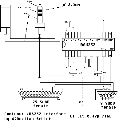
But, in the nineties Bastian Schick already developed a ComLynx to RS232 cable that allowed you to connect your Lynx to a PC with a COM port.

cl_232

Since I am no hardware or electronics expert I decided to go a different route: create a ComLynx to USB myself. That would also solve the problem of requiring a computer that still has a COM port. I know mine doesn’t have one. There has been talk about building a ComLynx to USB cable in the AtariAge Lynx forums before. GadgetUK managed to build one, as you can see in the pictures there. He also wrote a .NET program Zeus (with sources) that works excellently and allowed me to test-drive the cable.

Getting started

The Lynx uses UART to let the consoles to talk to each other. There is a lot of material available on the Internet. You could even read a part of my tutorial that brings you up to speed on the Lynx and UART.

Let’s take a look at what a ComLynx cable looks like:

There are two male and one female connector. You can read more about this at a previous blog post. Inside the ComLynx cable there are two wires. I never ever opened a ComLynx cable up. So, in the interest of science I cut open the cable at the end that has the single male. The idea was that I could still use the other end to link to more than one Lynx. Here’s the inside of the cable:

WP_002196 (2)

The cable shows two wires only. After some reading and measuring I came to this conclusion:

  1. Red: Corresponds to the +5V that the ComLynx uses for the high signal of the UART and is the combined receive (RX) and transmit (TX) signals
  2. White: Ground cable (GND)

Alright, that part was easy. The next part is to find some piece of electronics that can be used to connect to the PC via USB.

USB to UART hardware

Searching through eBay I selected the following USB to UART pieces of electronics that seemed to fit the bill: the required connectors (GND, RX, TX and optionally +5V) and cheap (ranging from ($2,60 to $8,05).

  1. Silicon Labs CP2102 USB connectivity bridge (driver)
  2. Prolific PL2303HX  (driver)
  3. FTDI FT232RL USB to TTL serial cable adapter (driver)

imageimageimage

I took the pictures from eBay to show what they are like. The first one is very bare, and uses a 6-pin connector. The second from Prolific has a casing and cable with a loose end. It’s the casing that is most interesting. Finally, the FTDI version has some neat connector-thingies at the end for each of the six loose wires.

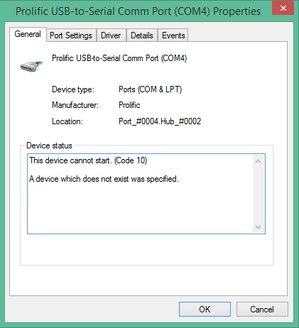
Now, a thing to note is that the Prolific one. It turned out that the chipset that is used in this connector is sometimes a fake Chinese one, not the original Prolific. The latest drivers from Prolific will detect and reject the chipset. The result is a Windows device that is detected, but lacking driver support.

image

In the properties of the device error code 10 is shown.

image

Apparently the older drivers did not have this fake chipset detection and worked OK. The older driver that was referenced in the eBay auction might help. Some more info I found here.

I do not know if mine is a fake one. There is also no support for Windows 8 for the HXA model, whether it is fake or genuine. I should have read the description better.

Installing USB drivers

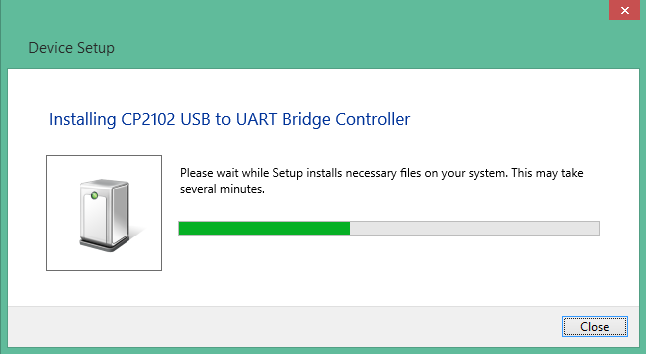
The Silicon Labs and FTDI USB devices both installed pretty smoothly. Once inserted in your USB slot Windows will detect it and (attempt to) install its own drivers first.

image

image

Windows is really helpful here and offers a link to the download location of the manufacturer.

image

The Prolific device does not have an appropriate Windows driver as part of the OS installation.

image

Windows 7/8 will find drivers for the FTDI one. However, these are not suitable. You will need to download the appropriate drivers from the manufacturer’s website. I’ve included the links to the drivers in the list above. Windows 8.1 has the drivers for FTDI out-of-the-box.

Running Windows 8 the registered FTDI device showed up as a FT232R, indicating that the driver is not available yet.

image

After that I installed the Virtual Com Port (VCP) driver from FTDI and the Silicon Labs driver. The end result is two properly registered USB to UART devices.

image

Building the physical wire

With the USB devices and driver troubles out of the way there is nothing holding us back in that respect. Let’s connect the ComLynx cable to the USB device.

I came up with two strategies:

  1. Connect/solder cable to the USB device
    Since I already opened a cable I might as well connect it to the USB device itself.
  2. Keep ComLynx cable and device intact
    This means that the cable will not be cut and the device will not require any cutting, soldering or whatever.

Soldering away

Going with number 1 first I looked at the back of the FTDI device after opening up the USB case. There I found that it neatly shows what each pin is used for.

TODO: New pictures

So, I soldered the red cable for combined RX and TX to the two pins that were indicated as RXD and TXD. The white ground wire connects to GND. The end result with the casing assembled again looks pretty swell.

WP_002201 (2)

When I did the same for the Prolific device, I couldn’t test that wire with my Windows 8.1 machine, because of the aforementioned incompatibility of the Prolific chipset.

I had already used the Silicon Labs version and that turned out to work alright as well. The end result wasn’t as pretty as the previous one, so I took it apart again and build the one shown above. When I rebuild it using the Silicon Labs device I will post new pictures here.

Inside the ComLynx connector

Since the other strategy would not allow me to mutilate the original ComLynx cable or solder at the device, I had to sacrifice another thing: the ComLynx connector. Fortunately I have several of those lying around from all the broken Lynx boards I acquired over the years.

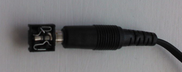
The next picture shows the loose connector’s back, front and inside.

image 

It may be kind of hard to see, but the back shows four pins:

  • Left side: a single pin that corresponds to RX and TX
  • Top side: again, a single pin for GND
  • Right side: two pins, of which I do not know the function (anyone care to comment?)

Here’s what the ComLynx cable looks like inserted into the connector.

image

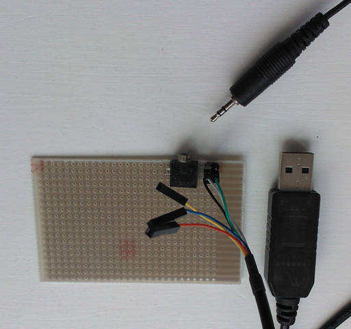
I used a simple solder board to align the top and left pin to two little connectors that can hold the individual wires of the FTDI device’s cable. The two pins at the right side (left facing the front) were bent outwards, so they wouldn’t connect or interfere with the rest.

imageimage

You can see how I soldered them to the board.

With that done I could finally insert the ComLynx cable into the connector. All that was left was to hook up the beautifully colored wires of the FTDI device to the little two connectors at the right of the ComLynx connector.

The color scheme for the FTDI cable (in my case) was like this:

Color Function
Black GND
Blue CTS
Red +5V
Green TXD
White RXD
Yellow RTS

That meant that the white and the green should be at the bottom row and the black cable at either one of the top pins.

image

Well, maybe not as neat as the previous one, but you don’t have to ruin a perfectly fine ComLynx cable nor solder the original wire. I might leave this as is or take the USB device apart to go for strategy 1 with it. I think it is more practical to have a single cable, instead of two separate cables and an open electronic board.

Test driving the cables

Aah, yes, the testing. At this point you will have to wait for my tutorial series to catch up. I did the first part on ComLynx already. The next one will show how to program the Lynx for UART and will make extensive use of the cable.

Or, you can ask for me to do a write-up before that. Feel free to ask any questions. Good luck building your own cable.

Posted in Hardware | 1 Comment

Programming tutorial: Part 13–UART

Atari Lynx programming tutorial series:

The previous parts we have looked mainly at graphics and memory. The Lynx has two other interesting features that set it apart from other handheld consoles. The sound and the ability to connect up to 16 Lynxes and allow them to communicate to one another. This part we will look into the details of ComLynx. ComLynx was the official name for the connection capability of one or more Lynx consoles. It will take more than one part to cover everything, so we will get started with the basics of serial communication and the hardware inside the Lynx. This helps understand how everything works and gives valuable insights before we move up an abstraction level by using the CC65 serial driver.

Primer in UART and serial communication

Before we dive into ComLynx we need a good understanding of UART and the serial form of communication that comes with it. UART is short for Universal Asynchronous Receiver/Transmitter and is a piece of hardware (an integrated circuit) that can do serial communication over a small number of lines. Usually the communication physical interface between two such hardware components consists of a cable that has a couple of wires, each with a dedicated purpose. Typically these are a ground (GND) and a receive (RX) and transmit (TX) line at a minimum. Other lines (CTS, RTS, DSR, DTR) can help create a more robust communication allowing for handshakes and transmission control. The Lynx does not have these, so let’s steer clear of those.

The RX and TX line can have a high (e.g. +5V, although the exact voltage may vary) voltage and low voltage (0V and again low might be a different voltage, potentially negative). Using the two voltage levels the lines can send bits across the line by alternating high and low to indicate 1 and 0 respectively. It is similar to morse code where the short and long beeps are also two distinct signals that allow you to build characters. Where it differs is that in this serial communication it is customary to have a particular transmission protocol.

The most common protocol used for communication defines a way to send/receive data and check that the data has arrived completely and without error. The terminology includes Mark (for the high signal, or 1) and Space (for the low signal, or 0). The idea is that each piece of data is surrounded by a start bit and stop bits. The start bit signals the start of the data to follow and serves as a sync point for the receiver to begin reading the data that follows using its internal clock. When the data has been sent, one or two stop bits follow to signal the end. The stop bits might be preceded with a parity bit that helps determine errors.

synchronous_transmission2(source)

The parity bit is something special. It can be used by the hardware to detect errors in some cases. The parity bit helps to determine and check the parity of the data. It works like this. The bits in the data that have a high value (1) are counted. The parity bit is chosen to be 0 or 1 depending on the kind of parity check. With ‘even’ parity the parity bit is determined to result in an even number of 1 bits. Similarly, ‘odd’ parity is used when the number must be odd, not even. For example, say the data transmitted was 10011001. That’s four ones, so that is an even number. With even parity the parity bit should be zero, otherwise the total number of ones including the parity bit will be odd. For odd parity it would be necessary to chose the parity bit as one resulting in 5 ones which is odd. Otherwise the total number would remain an even number. Whenever the parity bit is incorrect for the chosen convention (odd or even) it means an error condition has been detected. Since the check is based on a single bit with two values of which one is correct, it means that you will only find errors in 50% of the cases. Not perfect, but still better than nothing.
Three other options for the parity bit exist: None, Mark and Space. None means that no parity bit is included. The stop bit(s) will immediately follow the data bits in that case. Mark parity always has a high parity bit, and Space has a low parity bit.

Each bit that is transmitted is defined by the high- or low-ness of the line for a period of time. That time, the bit time, is determined by the clock speed of the UART. You have probably come across the unit of Baud, or “Bits per second”. It was pretty common to refer to your modem speed in Baud. E.g. my first modem was a Dynalink 14k4 baud modem, capable of transmitting 14400 symbols (or tones) per second. Although Baud and bits per second are not necessarily the same, it does hold true for the UART in the Lynx. For digital devices the symbols are bits, hence the reason that Baud and bits per second are equivalent.

UART in the Lynx

The UART of the Lynx is a circuit that lives inside of Mikey. The UART supports various baud rates, and has several settings for the parity bit. The baud rate is governed by the countdown value and frequency settings you provide to timer 4. The timer governs the pace in which the bit are transferred. All Lynx consoles should have the same baud rate to understand each others bit rate.

The data that is transmitted over the wire has the following 11-bits format:

image

The start bit and stop bit are always present and have a values of 0 and 1 respectively. This is a common choice as it will make sure that there is always a transition between the stop and start bit (1 to o). The data is sent with the least significant bit first (LSB).

The parity bit is set depending on a chosen setting. The Lynx supports the variations of Odd, Even, Mark and Space. The omission of None means that the 9th bit is always sent. Not all of the parity settings  are actually useable in a real-life scenario. For odd and even parity the bit is set appropriate. However, the hardware has a flaw that results in the parity calculation to include the parity bit itself. The Lynx can communicate with another Lynx just fine, because both have this bug. On the other hand, the Lynx will have a hard time communicating with non-Lynx devices (such as a PC with a serial port) that will check the parity bit the normal way.

The Lynx’s UART has a TX, RX and GND line for send, receive and ground. The peculiar thing about the Lynx wiring of the cable is that the RX and TX are connected together inside the ComLynx cable.

image

The design choice to connect RX and TX together has a lot of consequences:

  • The hardware now has the simplest setup.
  • Whatever a Lynx transmits is also received by himself.
  • The Lynx can detect when there is something connected to the ComLynx port, because it will be “short-circuited”.
  • No hardware or software handshakes are possible.
  • When one Lynx talks, all others must listen to avoid transmission errors.

Inside the UART there is transmitter and receiver hardware. For transmitting the UART provides a holding register and a shift register. The holding register can hold the next byte that must be sent. The shift register pushes the actual 8 data bits over the wire, wrapping it with the start, parity and stop bits.

To send something you first put a byte in the holding register. The hardware transfers it to the shift register when it is empty and ready to accept the next byte. Then the shift register starts sending it out. In the meantime you can put the next byte in the holding register, because that has become empty after the byte was transferred to the shift register.

Interrupt me

The UART send and receive mechanism uses timer 4 as its clock to generate the bit rate and it can fire interrupts (IRQ) when actually sending or transmitting. Indirectly the interrupts are a way of notifying you of a newly received byte or an empty holding register. In the interrupt handler you can check flags (TXRDY and RXRDY as we’ll see in a moment) to see whether a byte was sent or received. If so, you should put a new byte in the holding to keep the outbound dataflow going and you should read received bytes quick enough before the next one arrives. Should you be slow to put in a new byte to transmit, you’re wasting time sending all data. If you are too late to pick up a byte from the receive holding register, you will get an overflow because the receiver cannot place the new byte and lose some data.

It’s your choice whether you want to use interrupts for sending and receiving or not. Using interrupts you can continue doing other stuff, so this is a reasonable option when you are performing other tasks (gameplay is an example) and want to send and receive data in the meantime during interrupt handling. On the other hand, should you have a dedicated part of your program/game that does send or receive only, you can use the send and receive flags to check whether you should use SERDAT.

A programmer’s look at UART

Now that we know what the hardware looks like and how it behaves, it is time to look at the programming side of things again. The Lynx has various hardware registers inside Mikey that have a memory address so you can change settings for the UART hardware and help send and receive data.

First of all, the UART uses timer 4 to serve as the baud rate generator. So, by setting the time of each timer tick and the countdown period you can indirectly specify the baud rate. The baud rate is calculated by determining the time it takes to send 8 bits when timer 4 has a particular speed. The baud rate calculation is as follows:

clip_image002[12]

where rtimer4 and ftimer4 are the reload (countdown number) value and frequency of timer 4. The countdown value is set to a minimum of 1, but the timer will trigger when it underflows (from 0 to a virtual -1). It will need a minimum of two timer periods to trigger. The frequency inverted gives the number of clock ticks per seconds. The end result is the baud rate as it is frequently used (bytes per second) for devices, but not the official definition of bits per second.

Some examples:

Reload

Clock speed

Frequency

Baud rate

1

1 µs

1 MHz 1000000/((1+1)·8) = 62500 Bps
2

1 µs

1 MHz 500000/((1+1)·8) = 31250 Bps
12

1 µs

1 MHz 1000000/((12+1)·8) = 9615 ≈ 9600 Bps
207

2 µs

500 kHz 500000/((207+1)·8) = 300,5 Bps
255

64 µs

15625 Hz

15625/((255+1)·8) = 7,63

The most important two memory locations are SERCTL (0xFD8C) and SERDAT (0xFD8D). The first, SERCTL,  refers to the serial control register and allows you to change settings. SERDAT is where you will read or write the serial data.

SERCTL turns out to be a weird register. The behavior is totally different when writing to or reading from it. In other words, when you write a specific value, and then read it, you will probably get a different value from the one you wrote.

Bit

Write

Read

7 TXINTEN
Transmitter interrupt enable
The interrupt bit for timer 4 will correspond to the transmitter ready bit (i.e. you can put a new character in SERDAT)
TXRDY
Transmitter buffer empty
The buffer to hold data is ready to accept another byte. You can write it to SERDAT.
6 RXINTEN
Receiver interrupt enable
With this enabled the interrupt bit for timer 4 will correspond to the receiver ready bit (i.e. a character was received and can be read from SERDAT).
RXRDY
Receive character ready
A character was received and can be read from SERDAT.
5 0 (zero)
Future compatibility
No idea what they meant to keep compatible in the future.
TXEMPTY
Transmitter totally done
The transmitter has both an empty buffer and shift register. All offered data has been sent completely.
4 PAREN
Parity bit enabled
The parity checking is enabled and the parity bit will be calculated according to the odd or even setting (see PAREVEN).
PARERR
Received parity error
The data that was received had a parity error, so the parity bit did not match according to the parity setting.
3 RESETERR
Resets all errors
Writing a value with this bit set will clear all three errors (parity, framing and overrun) should they be set.
OVERRUN
Received overrun error
The data in the receive holding register was not read quickly enough. The new data could not be delivered.
2 TXOPEN
1: Open Collector
0: TTL driver
Choose between these two modes of transmission. A bug in the hardware causes the state of the output to be high after power up. The advice is to set the bit to Open Collector (1) to fix the problem.
FRAMERR
Received framing error
There was an error in the frame. That probably means that from the suspected start bit the stop bit was not received at the expected moment. It usually means that more than one Lynx is sending at the same time.
1 TXBRK
Sends a break
For as long as this bit remains 1.
It should be set at least for a 24 bit period according to the current baud rate. The specification mentions that a break is a start bit followed by 8 zero data bits, a parity bit and the absence of a stop bit at the expected time.
RXBRK
Break received
A break was received because for at least 24 bits of transmit time, there was a high signal.
0 PAREVEN
1: Even parity (or Mark)
0: Odd parity (or Space)
This parity is used for both sending and receiving. When PAREN is 1 these parity values are used. If PAREN is 0 then the value in parentheses is used (Mark or Space) as the value of the 9th bit.
PARBIT
9th bit
This bit reflects the parity bit of a received frame. It is set to the parity calculation when PAREN is 1. Or it is whatever PAREVEN is at sender when PAREN is 0.

A deeper look at the way the data is being transmitted will explain how the byte travels through the UART transmitter. It is important to realize that the TXRDY bit refers to the holding register, while the TXEMPTY bit represents both empty state of the holding and the shift register.

Here’s how the various states of the TXRDY and TXEMPTY bits change throughout the lifecycle of sending. The scenario shows how two bytes are sent in sequence from the start when no transmission has been done yet.

         image At first the holding register and sending shift register are both empty. TX is ready and empty.
  image A byte is loaded into the holding buffer by a write to SERDAT. TX is no longer ready nor empty.
         image The byte is transferred from the holding to the shift register. TX is ready for new input in the holding register.
image The shift register is pushing out the bits of the data. In the meantime new data is loaded into the holding register.

The reverse is true for receiving data, except that the data is eventually put into the receive holding register, which can be read from SERDAT.

The UART will always check the parity bit on received data whether PAREN is set to enabled or not. It does look at the PAREVEN bit, so for Even and Odd a calculation is done, but for Mark and Space it only compares the value of the bit to the setting. Any parity errors are always reported through the PARERR bit in a read from SERCTL. You can inspect the value of the parity bit through PARBIT in the SERCTL register by reading from it.

Groundwork done

OK, no coding just yet, but a lot of background on the UART in the Atari Lynx and how it works. This will help us get started with the ComLynx features. Next time we will look at the way CC65 provides serial communication and also how to dig a little deeper and get started with the interrupts and low level timers and registers.

Till next time.

Posted in Tutorial | 5 Comments

Lynx model 2 hardware revisions

I buy my fair share of Atari Lynx consoles at the Dutch Marktplaats. It’s an free-format eBay, without the hashle (nor guarantees) that eBay gives and imposes. A great place to pick up the Lynx consoles that people want to sell. The Dutch market was pretty good for Atari. At least, so it seems based on the number of Lynx consoles that are sold by individuals.

The Atari Lynxes that I find are usually in great shape, give or take the odd scratch that is on the screen. Still, on a number of occasions, a dead console arrives. Usually I knew about it beforehand, but wanted to give it a try to fix it. That succeeds about half the time. From the ones that were dead beyond repair I always took the spare parts (outer casing, battery cover, LCD panels), whatever was salvageable. That included the motherboards.

A while back I noticed that the two Lynx models have different hardware revisions each. Yeah, yeah, I know they are different from model I and II, but I mean that there are model II consoles that have different hardware, and so does model I.

I am going to focus on the model II revisions for now. I found at least 4 different types:

  1. C104129-001 Rev. 2
  2. C104342-001 Rev. 1
  3. C104424-001 Rev. 1
  4. C104471-001 Rev. A

The numbers of the revisions seem to be increasing in the part numbers that all start with C104XXX, where the XXX is the most significant reference. The revision numbers 2, 1 and A probably have a meaning, but I am not sure whether this is related to the particular part number or the revisions in general.

Revision C104471-001 Rev. A

This is the model II board that I come across most often. Around 80-90% of the Lynx II has this 471 revision.

WP_002081WP_002083

This revision has a small copper covering at the back. The front shows a shield that covers about 2/3 of the board. Underneath are the most important chips, Suzy, Mikey and the 2 RAM modules.

Revision C104424-001 Rev. 1

This revision has a darker green motherboard, but is remarkably similar to the 471 revision. Some of the visible chips at the left are different and bigger. It also has a marking in the top left corner that the 471 does not have.

WP_002084WP_002085

The backside shows a copper plate that covers the entire board. It has some holes and slots to facilitate the mounting of the board and to expose the connectors at the top. The soldering seems coarse and messy.

Revision C104342-001 Rev. 1

Another board that looks a lot like the previous ones. Notice that I removed a single HC74A chip at the bottom left. It used to be there though. I’ll try to get a picture of a complete board.

WP_002079WP_002078

The backside has the smaller copper cover and the Atari logo on the cartridge slot.

Revision C104129-001 Rev. 2

Now here is the odd-one-out board. The 129 revision is different in a lot of ways. Some differences that I discovered:

  • First, it doesn’t have the shielding at the front nor back. It shows the chips in plain sight. At least, I cannot remember desoldering the cover from this board. Someone else might have done it before I got it. The holes for the shield are present, but there is no residue-solder at them.
  • Mikey and Suzy are the VLSI chips instead of the ones from Atari. These still show the names of Mikey and Suzy and have no reference to Atari. They seem to be the same as the chips in the Lynx model I, having numbers VC5138-0002 Mikey Rev 2 and VC5139-0002 Suzy Rev 2 in both models (I and this II).
  • It has simple straight wires in between the connectors at the top, where the other revisions have copper coils.
  • The layout of the board is significantly different along the top right edge and right corner.
  • The left connector for the controls does not have the closing lid. Instead you simply push in the flat wire and it is stuck.
  • The cartridge slot has the Atari logo in it. The model I had the Foxconn logo and later revisions had only the part number on it.
  • The back of the board does not have the protective dark green plastic on it. It shows the wiring more prominently.
  • The board only has single set of holes in it. Where the other board have two holes close to each other at the right side, all holes are single for this board.
  • The potentiometers for volume and brightness are different, more flat.
  • The chips used for the RAM are smaller NEC chips D41464L-80 instead of the D41464C-10 used on the other boards.
  • The connectors at the top do not have the usual dots of glue to keep them down.

WP_002087WP_002088

Another interesting thing is that the board only works with the LCD panel that came with it. The LCD panel (or the flat wire) had some issues which made 5-10 screen lines turn black. I tried replacing the panel, but any other working LCD panel wouldn’t come to life with this board. Reversely, the LCD panel from this board did not work with another board. I have no clue as to what the reason is. Timing or cable pin layout maybe?

What else is out there?

The different revisions appear to be telling a story of how Atari improved the design of the hardware. From the outside nothing really changed. You cannot see from the console which revision of the hardware it has inside. But surely there are reasons for the updates.

I do wonder quite a few things at this point:

  1. What the reason for the changes?
  2. Did the revisions without covers and shields have lesser performance?
  3. Which ones are newer and which ones are older?
  4. Are the other hardware revisions out there for the Lynx II model?

Should you have any ideas or explanations, feel free to drop a comment.

Since the boards are broken anyway, I will desolder the shield plates and take additional pictures, then update this post. Also, I am going to take some pictures of the various Lynx I models that I have laying around and do a similar post on the Lynx I model revisions.

Posted in Hardware | 5 Comments

Programming tutorial: Part 12–Memory mapping

Atari Lynx programming tutorial series:

Atari Lynx memory hardware

The Atari Lynx has 64KB of RAM memory, provided by two 32 KB DRAM modules. 120ns 65535 x 4-Bit Dynamic NMOS Ram 18-pin to be more precise. The type of chips differs for the two Lynx models:

  • Model I: SHARP LH2464-10
  • Model II: NEC D41454C-10

image

The memory range that is available for programming covers almost the entire range of 64KB, starting from the address 0x0000 up until 0xFFFF. There are only a few addresses and ranges that cannot be used.

Memory arrangement

The memory of the Lynx has special ranges at the beginning and at the end of the 64K memory. The first 512 bytes and the last 1024 bytes are treated in a different way than normal memory outside these ranges, and both ranges behave differently from one another.

The first 2 pages of 256 bytes of memory is allocated/reserved for use by the CPU. The 6502 family (including the 65SC02 which is inside the Lynx) uses the first 256 bytes (from 0x0000 to 0x00FF) of memory in a special addressing way. This is called the zero-page memory and there are specific opcodes that make use of this very first 256 byte memory-page. Because all addresses start with 0x00 the CPU can address these locations in an optimized way. The second 256 bytes (0x0100 to 0x01FF) are used as the stack. Again, there are 6502 opcodes that allow you to push registers onto the stack and pull them from it again.

Since the CPU is hardwired to use the second page of memory, you cannot really use this address space. You can use the zero-page memory. Typically you would store often used variables there, both single byte values and double byte addresses, but not actual code (although you could).

image

The other memory range is from 0xFC00 to 0xFFFF is really special memory. More correctly, the memory is not really special, as the memory at these addresses is normal RAM. As a matter of fact, it is the memory addresses that are special, because depending on a software setting the addresses point to hardware instead of the RAM at the same memory location. This is called memory mapped hardware. In essence you get to “talk” to the hardware of the Lynx at the special memory addresses.

Most of the times you will read from these memory ranges and read values from the hardware, such as the joystick or a timer value. Other times you will write to the address and change the hardware, e.g. change settings of the Suzy sprite engine. Or, when the address is mapped to the underlying memory you will simply access the RAM.

A lot of spaces

The area from 0xFC00 to 0xFFFF is divided into four spaces.

image

These spaces overlap with the RAM. The spaces give access to the hardware that is mapped to the addresses inside each of the spaces. The blue arrows in the picture above show the routing that can occur for a particular address. Take an address inside Suzy space. Based on the routing (to be discussed later) you will turn left to Suzy space or right to RAM at the blue junction.

Let’s take a look at all four spaces and the particular hardware that is mapped inside each:

  1. Vector space
    Most of vector space is typical for 6502 CPUs. It holds a couple of vectors, or addresses pointers, that have special meaning to the CPU. These are the interrupt, reset, NMI vectors.
    The reset vector is used during booting of the CPU and indicates at which address pointer (2 bytes at 0xFFFE (low byte) and 0xFFFF (high byte) respectively) the CPU should start executing code when it is performing a cold boot. The interrupt vector holds the address pointer to jump to when an interrupt request (IRQ) occurs. Likewise, the NMI vector is the pointer for non-maskable interrupts (NMI). It is less relevant for a regular Lynx developer, as the Lynx hardware does not generate any NMI itself. Only the Howard development board used the NMI to trigger stuff inside the Lynx. Mere morals usually do not have a Howard or Pinky board.
    Two other memory addresses are inside the vector space. They are not vectors, but rather a reserved address (0xFFF8) and a memory map control (0xFFF9, or MAPCTL) register. We will discuss the MAPCTL address in more detail later.
  2. ROM space
    The area from 0xFE00 to 0xFFF7 is called the ROM space. This area references 512 bytes of ROM memory that is hard-baked into the Lynx CPU. This ROM memory contains the boot code that the Lynx executes during startup. It takes care of the Lynx hardware initialization, decrypting of the cartridge header and loading the first file on the cartridge. The boot code is available on the Internet as the famous LYNXBOOT.IMG file needed for the Handy emulator. It is Atari proprietary code and you are not allowed to distribute it. This is the reason that it is not included in the current emulators like Handy and Mednafen. During booting the addresses point to the ROM inside the CPU and the Lynx will be reading from the ROM instead of the RAM that is also at the same addresses.
  3. Mikey space
    The Lynx’s CPU is a customized 65SC02. It behaves like a normal 65SC02, with additional functionality like the spaces we are discussing now. This chip is nicknamed “Mikey”. Mikey talks to most of the Lynx hardware and has specialized timers and audio registers.
    The hardware of the Lynx is accessible through the memory range inside Mikey space. For example, the AUDIN address 0xFD86 is the AUxiliary Data IN and is connected to the same-named pin on the cartridge. By reading and writing to this address 0xFD86 you effectively control the value at the cartridge pin AUDIN and set it to a 0 or 1 value.
  4. Suzy space
    The Lynx has another custom chip and it’s called Suzy. Suzy takes care of the math, joystick and buttons and holds the sprite engine. The functionality of Suzy is used by reading and writing to the Suzy space address range. Again, in effect the address range might map to the hardware or the underlying RAM depending on the memory map control setting we will discuss in the next paragraph.
    You have already seen some of the addresses when we talked about the sprite engine. Remember the SPRSYS that was mentioned for sprite collisions? This address equates to 0xFC92 and is the register that has system control bits. One of those bits, bit 5, is the bit that enables or disables collision detection globally. So, by writing either a 0 or a 1 at byte 5 for SPRSYS will enable or disable collisions for all sprites.

You will need to have the Epyx Lynx documentation close at hand to read about all the special addresses inside each of the spaces. You can find those at AtariAge Lynx archivesLynx Developer Documentation” as the “Handy appendix 2 Hardware Addresses”.

Taking control of memory spaces

You have seen all four memory spaces now. Each of the four ranges have addresses that either map to special registers or hardware, or to the RAM at these locations. You might wonder how it is determined where the addresses point to. The answer to that question is the MAPCTL register at 0xFFF9. The MAPCTL represents the way the address bus is wired and to which side of the memory map the switches are set.

Each of the bits inside the MAPCTL has a particular function and meaning. The 4 least significant bits 0 to 3 are space disable bits. Setting a bit to 1 will disable the corresponding space and give access to the underlying RAM instead of hardware/registers.

image

The bits 4 to 6 are reserved for future use. Like that is ever going to happen. And the most significant bit 7 is the sequential disable bit, that will make the CPU always use full cycles (5 ticks minimum), never a sequential cycle of 4 ticks. I would encourage you not to mess with that bit and always leave it at 0.

Okay, assume we wrote the value 0x0F to MAPCTL. That means it will write the following bits 0b00001111: 4 zeros for the most significant and 4 ones to the least significant bits. This means that all four spaces are disabled and you will be able to access the full range of RAM memory. Writing 0x00 on the other hand will leave the spaces enabled and you will access the hardware and registers instead.

Most of the time you will need both Suzy and Mikey space enabled to be able to use their functionality. If you are really pressed for memory you could disable ROM pretty safely, and Suzy and/or Mikey selectively whenever you do not need to access the memory mapped hardware addresses.

To illustrate how the Lynx itself uses MAPCTL consider this: during the boot process the MAPCTL is set to 0x80 initially by the boot ROM values. The code that is executed sets it to 0x03 afterwards, effectively disabling Suzy and Mikey and allowing access to the RAM from 0xFC00 to 0xFDFF by setting b0 (Suzy space) and b1 (Mikey space) bits to 1 (disable). This is what the memory map will look like for 0b00000011.

image

Note that disabling the spaces does not disable the hardware. It just isn’t possible to read and write to the hardware using memory addresses while it is disabled.

Executing code

The CPU will always execute code that is loaded into RAM memory. The one exception is during booting of the Lynx when ROM space is enabled and the code is executed from the baked-in memory. The Lynx is “notorious” for its inability to map to the ROM memory on a cartridge. This implies that the code on a cartridge must always be loaded into RAM before it can be executed. The same goes for game data (e.g. sprites, other graphics and level data). The loading is made easier with some library functions, but it is not as convenient as simply accessing memory ranges that map to cartridge ROM instead of RAM. Looking on the bright side: it is a simple model where everything is either RAM or potentially hardware (above 0xFC00).

Managing the memory map

With all the above said let’s look back and see what we need to do during development and when our code is executing.

First of all, I think you should check how much memory your program will need. Small programs might not need every single byte from the 64K. When you read the stories of 8-bit developers you will realize that most of them mention the small amount of memory that is available (at all). So, it is safe to assume that you will need as much memory as possible.

Next, you could look into the areas of your game or program that need access to Suzy and Mikey. If there are moments where no access is needed, but memory is used intensively you could disable Suzy and Mikey space and use the memory underneath during those moments.

The include file from CC65 called _suzy.h defines constants for the various bits in the MAPCTL:

/* MAPCTL $FFF9 */
#define HIGHSPEED       0x80
#define VECTORSPACE     0x08
#define ROMSPACE        0x04
#define MIKEYSPACE      0x02
#define SUZYSPACE       0x01

The _suzy.h include file is automatically included by the lynx.h include file that was already a part of your Lynx programs.

Here’s a tiny bit of code that will set MAPCTL to disable Suzy and Mikey space and give access to the RAM from 0xFC00 to 0xFDFF:

POKE(0xFFF9, MIKEYSPACE | SUZYSPACE);

There is no special define for 0xFFF9 inside _suzy.h, _mikey.h or lynx.h, but you could define it yourself like so:

#define MAPCTL		0xFFF9

which would make the previous code sample as follows:

POKE(MAPCTL, MIKEYSPACE | SUZYSPACE);

Other things to note

During the boot process the Lynx boot ROM code will erase all memory and write zeros to all addresses. After that it will load the title screen and the program code. You cannot assume you start off with an zeroed out memory, although the CC65 libraries will take care of most of the ugly details of loading ROM into RAM and zeroing BSS variables in RAM.

Also, the aforementioned include files _suzy.h and _mikey.h hold two struct definitions that nicely wrap the access to the hardware addresses (inside the Suzy and Mikey address space). It is recommended to use the defined values SUZY and MIKEY to access these addresses instead of going for the PEEK and POKE route.

Next time

Now that we know what the memory looks like and how it is managed, it will be time to do some loading of ROM data from cartridges. Then again, who knows what the next installment will bring. Wait and see. Till next time.

Posted in Tutorial | Leave a comment

Starting a new project: Hack Slash Loot

Early 2013 I pondered what to do for the next incarnation of Tiny Lynx Adventure. There was demand for a v2.0 version with improved graphics and sound. So, I set out to find some open-source tilesets and graphics that I could use. After spending a terrific evening searching for that, I found graphics by Oryx (http://forums.tigsource.com/index.php?topic=8970.0) and Oddball (http://forums.tigsource.com/index.php?topic=8834.0).

The Oryx tileset is actually derived from the work of Oddball. The good thing is that both tilesets use only 16 colors (like the Lynx’s color palette). They are pretty complete and cover both tiles for the surroundings, enemies and items. In short, a pretty good start to go build your own RPG like adventure. There are a couple of incarnations that use these tilesets, of which I found Legends of Yore a particularly good one.

Looking further I found that oddball, whose real name is David Williamson, has improved his tileset and used it in a terrific game called “Hack Slash Loot”. It is available from his website at http://www.hackslashloot.com and through Steam.

Hack Slash Loot is an unforgiving game, in the style of a Rogue-like, with PermaDeath (no saves, one live. If you die, you need to restart). It is also a beautiful game, that is very addictive once you get started and get the hang of it. There is a deeper level to the mechanics of combat, with vulnerabilities and resistance to certain types of attack. Understanding that makes the game easier to play and finish.

Header logo

I really fell in love with the game, gameplay and its graphics. I also saw an opportunity to get this on the Atari Lynx. It should be feasible (so I thought) with some adjustments for screensize. With this in mind I set off to build a Proof-Of-Concept (POC) for the graphics and display of the dungeons. Satisfied with the results of that I contacted David Williamson and asked for his permission to do a port of the game. His reaction to my request was very enthusiastic and he permitted and encouraged me to try and fit it on the Lynx.

That was February 2013. I set off on a long journey to first prove that I could do most of the technical stuff that was required to build the game:

  1. Resource management
    HSL has a lot of graphics. And I mean a LOT! Hundreds of artifacts, thousands of items, such as weapons, shields, potions, and countless enemies. This will never, ever fit into the available memory on the Lynx, not even if you could use all 64KB at once.
  2. Line-of-sight or room discovery
    When you explore you will reveal more and more of the dungeon that starts out all black except for the room in which you begin your quest.
  3. Path finding for critters
    The enemies need a way to try and reach, then attack you. Likewise, friends need to be able to follow you. The finding of available paths through the dungeons is particularly compute-intensive and really hard to do with limited memory.
  4. Dungeon generation
    All dungeons are generated randomly based on some parameters like noise blocks and number of walls. Also pretty compute heavy and rather complicated.
  5. Mapping dungeon
    The game features a map of the dungeon level you are currently on.

It’s now July 2013 and I have worked on this project on and off in my spare time. I tackled all of the hurdles mentioned above. At this point I have enough confidence that this is actually doable. Hence, this announcement of the work in progress.

I put a video up on Youtube to see what it currently looks like.

Work in progress video footage

Some remarks about what you see:

  • There is no HUD at the bottom. The graphics still need to be created, but the text for the things you see/discover/attack is there. Just imagine a border like in the screenshot of HSL.
  • At the left a weird black block is shown. This is a placeholder for the HUD border from the previous point.
  • Enemies have limited AI and only try to reach you. They do not attack yet. Also, they are allowed to stand on top of each other, which is why it seems that they are disappearing.

Besides the help from David, there are a couple of other people helping me out. Jack Menhorn is the composer of the music for the game and is creating MIDI files to add the conversion. Daniel Horvath (108stars) will do some of the graphics and Sascha (Der Luchs) is working on the conversion of the music in the game. Chris (GadgetUK) and Leny (obschan) and Karri Kaksonnen have been very helpful in finding technical solutions and solve bugs. With these people to back me up, there is hope that this will eventually be released.

Posted in Homebrew | 8 Comments

Tiny Lynx Adventure

It’s been a while since this was released, but I never got around to putting this on my blog. You see, I created my first complete game for the Atari Lynx and put out both the ROM file in LNX format and the source code.

snap03

The game is based on a sample called adventure.asm by Norman B. Lancaster which you can find on the www.6502asm.com website. Simply select that file from the dropdown, press Compile, then Run and play with the WASD keys to move. I found that small sample so enjoyable to play, simple as it looks and works, that I chose it as my learning project.

Here are some simple instructions from the original source:

; Thank you for trying my game! You are Good Guy, and you are on a
; quest to defeat Bad Guy, the only other guy in this area of The
; World.
;
; You start in the forest. Somewhere within the forest are a pair of
; flippers, which will allow you to swim in the river. Somewhere along
; the banks of the river there is a key to the White Castle. Within the
; White Castle are a protective crown and a deadly weapon (it looks
; like a red star thingy). These two items are needed to defeat Evil
;
Guy.
;
; Evil Guy lives in the Black Castle, which you can get to through the
; desert. Conveniently enough, the key to the Black Castle is somewhere
; in the desert.
;
; Find Evil Guy in the Black Castle while wearing the crown and weapon
; and you win! If you lack either the crown or weapon, the screen will
; flash only red, and you will loose!

The game is minimalistic and has no sound and only simplistic graphics (like the original). Yet it also has a nifty feature that might make it fun to replay: random item placement. The world stays the same, but the items will spawn at random locations in the world.

Known issues:

  • The game can only be played once. You will need to turn your Lynx off and on (Flashcart or EEPROM burner owners) or reset Handy (F3 on Windows)
  • No savegame feature
  • The screen does not flash red when you loose from Evil Guy. Instead you get the Game Over screen.

Here are screenshots to  give you an impression of the game:

snap02snap05snap04snap06snap07snap08

The pictures show the start screen, the death star weapon and crown items and the entry of the black castle. Finally there’s Evil Guy and the victory screen.

Somehow the game got picked up by Retro Gamer Magazine in the Homebrew section. Jason Kelk reviewed the game and had this to say about it:

TinyLynxAdventureCutout

“The dastardly Bad Guy is in need of defeating and Good Guy, the only other person in this particular part of The World, has been sent to sort him out. But evem getting to Bad Guy is going to take a lot of exploration. Not only that, but Good Guy will also need to locate a pair of floppers to swim through otherwise impassable lakes, search the desert for a key to open the ominous-sounding Black Castle and, unless the protective crown and deadly weapon are also retrieved, trying to take on Bad Guy will automatically prove fatal for our hero.
The blocky graphics and non-existent sound – both due to the original game being written for an online 6502 emulator – really don’t do the Lynx system any justice at all, but somehow, even though the gameplay is limited to just exploring and collecting the occasional object, it’s still and entertaining undertaking.
We’d really like to see an improved version of this game which adds some enemies to fight, treasures to discover and audiovisuals that take proper advantage of the hardware.”

Jason Kelk gave the game a whopping 80%, which is pretty good for the game it is.

Included for your convenience are the game and its source code: Source code and Rom file in my Atari Lynx SkyDrive folder. You can read about the discussion around TLA on the Atari Age forums for the Lynx.

Drop me a comment if you are interested in reading a technical lowdown on the game or if you want the source code to be upgraded to the latest CC65.

Posted in Homebrew | Leave a comment