Physical design of a compact injector for synchrotron-based proton therapy
 Jian Qiao1,2,3,4†‡
  Nan Yan5,6† Zike Huang1,2,3,4†‡ Yang Zhong1,2,3,4
  Jiazhou Wang1,2,3,4 Xiucui Xie5* Yuehu Pu7,8,9*
  Weigang Hu1,2,3,4*
- 1Department of Radiation Oncology, Fudan University Shanghai Cancer Center, Shanghai, China
- 2Department of Oncology, Shanghai Medical College, Fudan University, Shanghai, China
- 3Shanghai Clinical Research Center for Radiation Oncology, Shanghai, China
- 4Shanghai Key Laboratory of Radiation Oncology, Shanghai, China
- 5Shanghai Institute of Applied Physics, Chinese Academy of Sciences, Shanghai, China
- 6University of the Chinese Academy of Sciences, Beijing, China
- 7West China Hospital, Sichuan University, Chengdu, China
- 8Medical Device Regulatory Research and Evaluation Centre, West China Hospital, Sichuan University, Chengdu, China
- 9Medical Equipment Innovation Research Center, Med+X Center for Manufacturing, West China School of Medicine, West China Hospital, Sichuan University, Chengdu, Sichuan, China
A compact room-temperature linear injector has been purposed to accelerate an 18.0 mA proton beam to 7.0 MeV for synchrotron-based proton therapy. The total length is appropriately 5 m. It mainly consists of a 3.01 m radio frequency quadrupole (RFQ) and a 0.82 m compact interdigital H-mode drift tube linac (IH-DTL) structure. Based on a fast-bunching strategy, the RFQ, operated at 325 MHz, accelerates protons to 3.0 MeV. The phase advances have been taken into consideration, and parametric resonance has been carefully avoided by adjusting the vane parameters. After the modulation of the transverse and longitudinal phase advances and a compact external quadrupole triplet, the proton beam is injected into the subsequent IH-DTL. Based on modified Kombinierte Null Grad Strukter (KONUS) beam dynamics, it accelerates protons up to 7.0 MeV, which is composed of a re-bunching section and an accelerating section. The accelerating gradient reaches 4.88 MV/m. The overall dynamic simulation results show that the whole accelerating gradient reaches up to 1.62 MV/m with a transmission efficiency above 95%. The transverse and longitudinal normalized RMS emittances at the exit of the DTL are 0.23 π mm·mrad and 2.216 π keV/u·ns, which meet the synchrotron injection requirements. The details of the specific design of this injector are presented in this paper.
1 Introduction
According to the latest estimations and investigations of the World Health Organization in 2022, the global cancer burden shows a rapid growth trend, and it is estimated to have risen to 18.1 million new cases and 9.6 million deaths [1]. Cancer has gradually become one of the major public health problems [2]. Therefore, the applications of the accelerator in treating, especially proton therapy, are expanding because of the characteristics of the accelerated protons in energy deposition. The Shanghai Institute of Applied Physics has been working on proton therapy facilities for 10 years [3–8]. The Advanced Proton Therapy Facility [8] is the first domestic proton therapy facility in China. To upgrade the original injector purchased from abroad, a compact scheme has been proposed and Figure 1 shows the overall schematic layout.
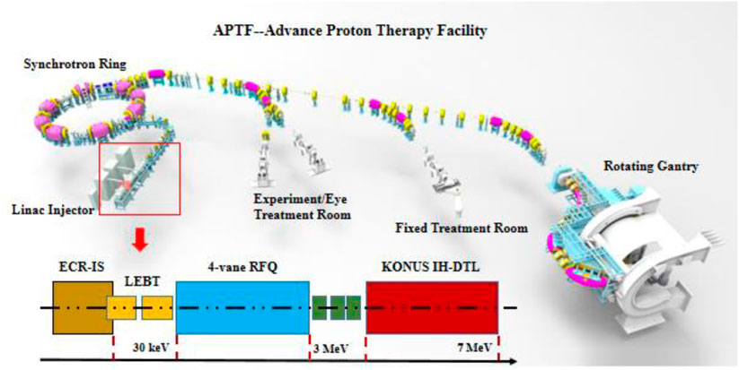
FIGURE 1. The specific design scheme of this injector.
This injector consists of an electron cyclotron resonance (ECR) proton source, a low energy beam transporting line (LEBT), a 3.0 MeV radio frequency quadrupole (RFQ), a compact triplet external matching section, and a 7.0 MeV drift tube linac (DTL). Table 1 lists the specific design parameters.
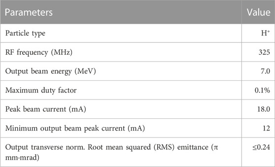
TABLE 1. Basic design parameters.
The main considerations are as follows.
1. Fast-bunching philosophy is employed for the design of the RFQ [9, 10].
2. A modified KONUS dynamics [11] is developed to simplify the R&D of the DTL. That is, there is no magnet inside the DTL cavity, which is convenient for integrated processing and maintenance.
3. A single RF power source is utilized to provide RF power for both sub-cavities. The RF is decoupled between both sub-systems and the phases are adjusted independently by two phase shifters.
4. Two methods are adopted for matching the designs of the RFQ and DTL. One method is to adjust the vane-tip modulation at the end cells of the RFQ to match the phase oscillation of the DTL, and the other method is to use a simplified external triplet matching section with no buncher for transversal matching.
The PAMTEQM [12], TOUTATIS [13], LORASR [14], and TraceWin codes [15] are applied for the design and simulation. The detailed design processes are discussed further in the following sections.
2 RFQ section
Based on the traditional four sections design strategy [16, 17], a four-vane RFQ structure is adopted because of its relatively even distribution of surface current density, easy cooling, stable structure with higher mechanical strength, and higher shunt impedance at a higher frequency. A trade-off optimizing strategy is considered to appropriately decrease the injection energy and cut down the inter-vane voltage to shorten the cavity length, reduce power consumption, and stabilize operation.
2.1 Decrease injection energy
Generally, a complete RFQ is composed of four sections, namely, the radial matching section (RM), shaping section (SH), gentle bunching section (GB), and accelerating section (AC) [9, 16, 17]. The front three sections are mainly in the low-energy region. According to the cell length formula:
However, due to the increase of the space charge effect in the lower energy section, lower input energy may lead to larger emittance growth. Additionally, the input energy is concerned with the extraction voltage of the ECR proton source. There are two conditions in choosing the extraction voltage, adequate beam intensity with relatively good quality and a reduction of the sparking risk.
Therefore, combining other RFQs currently in operation with previous design experience, the input energy is confirmed to be 30 keV.
2.2 Selection of inter-vane voltage
Compared with the ramped inter-vane voltage, a constant inter-vane voltage design strategy [18] is good for simplifying processing and operation difficulty, and it can reduce the dissipated peak power. Therefore, the constant inter-vane voltage strategy is applied.
An appropriate magnitude of the inter-vane voltage should be selected to ensure long-term stable operation and reduce the sparking risk. High inter-vane voltage is beneficial to bunching and accelerating beams, but it increases the power consumption and sparking risk. Currently, the Kilpatrick factor is the main reference standard [18]. The radio frequency f (MHz) and Kilpatrick field Ek (MV/m) follow the empirical formula 1 [18]. With the continuous progress of processing technology, the Kilpatrick coefficient b is applied in evaluating the sparking risk, as shown in formula 2. Table 2 summarizes the parameters associated with the RFQ currently in operation with a frequency close to 325 MHz. The coefficient is usually set below 1.8, and the inter-vane voltage is chosen in the range of 70–80 kV.
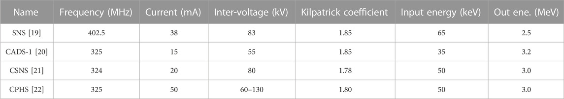
TABLE 2. Parameters of RFQs in proton accelerator facilities under operation or being commissioned.
The transverse focusing strength can be defined as shown in the following formula 17:
where
Based on formula 3, the focusing strength B can be increased by reducing the aperture and increasing V. The aperture changes as a function of z when B varies along the RFQ and V remains constant. However, a smaller aperture would limit the acceptance and increase error sensitivity in machining and assembly. Therefore, combining various factors and past design experience, as shown in Table 2, the coefficient is set to 1.7, which means that the Es value is appropriately 30.6 MV/m and that the inter-vane voltage is up to 75 kV.
2.3 Fast-bunching optimization strategy
According to Kapchinsky’s adiabatic bunching condition [11, 12], the traditional GB section is separated into two sections, namely, the pre-bunching section and the bunching section. In the pre-bunching section, the electrode modulation factor m evolves slowly from small values (close to 1), and then there is a fast ramping in the bunching section.
A fast-bunching optimization strategy, namely, a smaller m value in the SH section and a fast m ramping process in the GB section is adopted to replace the traditional long adiabatic bunching section and to further shorten the cavity length and achieve an efficient bunching process. The modulation coefficient m is optimized to ensure that the aperture a is within the allowable range of matching. Figure 2A presents the evolution curves of m before and after optimization. Compared with the traditional design, the entire length of the RFQ is shortened.
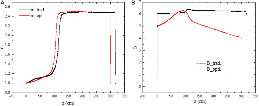
FIGURE 2. Evolution curves of (A) modulation factor “m” and (B) focusing strength “B” before (black lines) and after (red lines) optimization.
To avoid the parametric resonance, the transverse and longitudinal zero current phase shift
where B is the transverse focusing strength,
Figure 2B compares the optimized transverse focusing strength B with the traditional design. In the fast-bunching section, the B is increased to suppress the gradually growing defocusing effects such as the space charge effect and RF defocusing effect and to speed up bunching. However, in the accelerating section, as the particle velocity increases, the defocusing effect is weakened and B is accordingly reduced to weaken the longitudinal emittance growth and obtain a large aperture. In addition, by reducing the B, the phase advance per focusing period can be reduced accordingly. This can better match the subsequent DTL and reduce the focusing and matching pressure of the triplets.
According to the matched beam envelope equation, the normalized RMS emittance ε can be described as follows [16]:
By changing the transverse phase shift
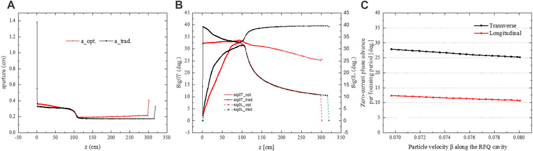
FIGURE 3. Evolution curves parameters. (A) Aperture “a”, (B) transverse and longitudinal zero-current phase shift
The units of the end of RFQ are designed carefully to better match the subsequent accelerating elements longitudinally with no buncher in the matching section. Figure 3C presents the optimized result of the zero-current transverse phase shift per focusing period in the transverse and longitudinal directions. The phase shifts are 25.3°. And 10.8° at the exit of the RFQ in both directions.
Table 3 lists the detailed beam dynamics design results. Compared with the traditional design, the optimized design based on the fast-bunching strategy is more compact and the beam quality is better. Figure 4 exhibits the evolution of the main parameters, including the focusing strength B, modulation m, synchronous phase
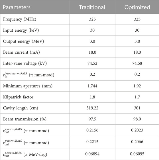
TABLE 3. Beam dynamics design results for the traditional and optimized design.
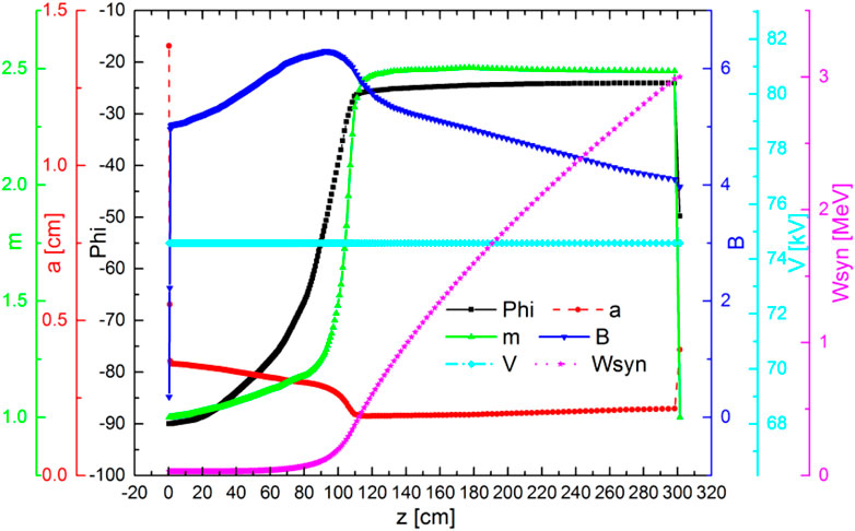
FIGURE 4. Main parameters of the RFQ (focusing strength B modulation factor m, synchronous phase
In this design, the maximum modulation coefficient is 2.5. The value is close to the value of the RFQ in Linac4 [23], and the maximum synchronous phase is up to −25°. The total number of cells is 311 with a length of 3.01 m. The overall emittance growth percentages in the horizontal and vertical directions are appropriately 1.15% and 3.3%, respectively, which are acceptable for the subsequent cavity.
2.4 Multi-particle simulations
Weighing various factors, the design strategies are chosen. The transmission efficiency is appropriately 98.0% in the PARMTEQM code, while the total transmission efficiency is about 98.89% in the TOUTATIS code, and the transmission efficiency is appropriately 98.1%. The small difference is mainly due to the different evaluation criteria for beam loss. Figure 5 shows the RFQ simulation results, which presents the multi-particle simulation result as well as the transverse and longitudinal phase space evolution along the RFQ longitudinal position. A total of 1,000,000 macro-particles, with a 4D water-bag input distribution, are injected. Beam loss mainly occurs at the end of the fast-bunching section and the front end of the accelerating section.
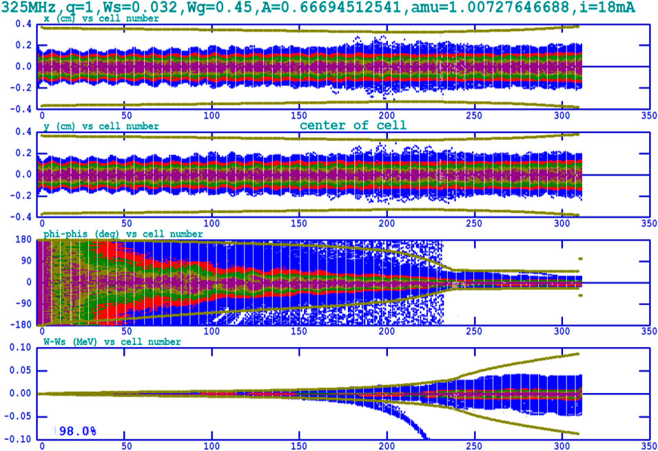
FIGURE 5. Multi-particle simulation results of the RFQ.
The phase shift at the exit is approximately 15° and the energy spectrum is about 20 keV, which can effectively meet the acceptance requirements of the subsequent KONUS IH-DTL and help to weaken the difficulty of longitudinal bunching for the subsequent DTL. Twiss parameters at the exit of the RFQ are used as the input beam parameters of the external matching section.
Figure 6 exhibits the various parameters and particle distribution evolution along the longitudinal position using the TraceWin code. Figure 6A shows the evolution of normalized RMS emittance. Due to the strong space charge force and weak transverse focusing force at the entrance, the transverse emittance grows significantly. Owing to the fast bunching, the longitudinal normalized RMS emittance at the GB section grows sharply within an acceptable range. Then the normalized RMS emittances tend to be stable in the acceleration section after some particles are lost at the end of the bunching section, which is illustrated in Figure 6B. As is shown in Figure 6C, the Kilpatrick coefficient along the longitudinal position changes smoothly, and the maximum is approximately 1.7 at the bunching section, which meets the design and processing requirements. Figure 6D illustrates the fact that the loss of particles mostly occurs at the end of the fast-bunching section.
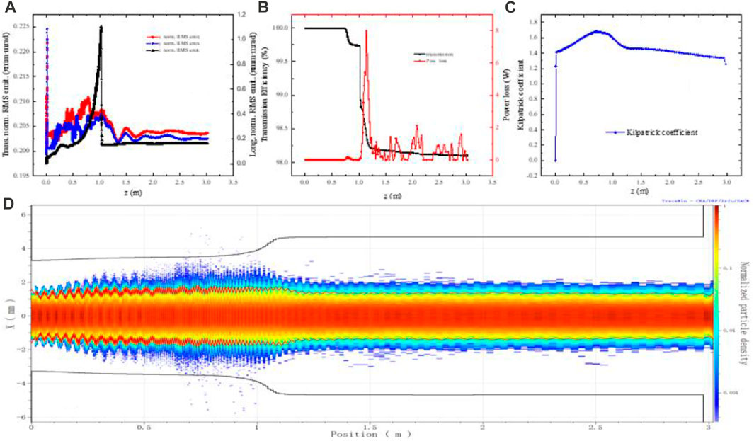
FIGURE 6. Parameters evolve along the entire cavity using the TraceWin code. (A) Normalized RMS emittance, (B) transmission efficiency, (C) Kilpatrick factor, and (D) particle distribution.
3 DTL section
The quadrupole magnets were utilized in the external matching section. After the matching process, the proton beam is injected into the downstream DTL. The input beam parameters are listed in Table 4. To shorten cavity length and simplify the fabrication and installation process, the inter-digital H-mode (IH) DTL, with a higher shunt impedance than Alvarez DTL, is considered [16, 24, 26].
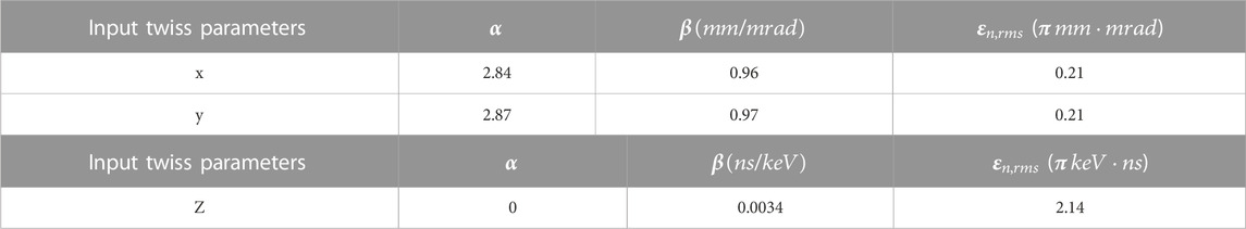
TABLE 4. Input twiss parameters.
3.1 DTL design strategy and discussions
For the IH-DTL, there are two kinds of dynamics principles, namely, Kombinierte Null Grad Strukter (KONUS) [15, 24, 25] and Alternative Phase Focusing (APF) [26]. Generally, the APF principle is mainly used in weak beam currents. The synchronous phase varies in different gaps from −90° to 90° in a certain pattern, which invisibly reduces the acceptance and acceleration efficiency. Therefore, the KONUS beam dynamics principle is applied.
According to the KONUS beam dynamics principle [15, 24, 25], a traditional period usually consists of three separated sections with different functions, and these sections comprise a negative synchronous phase bunching section, a transverse focusing section with a quadrupole triplet, and a zero phase acceleration section, respectively. This can effectively solve the contradictory situation of longitudinal acceleration, bunching, and transverse defocusing. The LORASR code [14] is employed for the design and simulation.
In this design, a modified KONUS principle is used, which means that the transverse focusing segments inside the cavity are moved outside the cavity and that the entire cavity is composed of bunching sections and accelerating sections.
The key parameters are as follows.
1.The phase shift at the junction between two sections, which is a transition from a negative phase to zero phases.
2.The geometrical length optimization of the transition drift tube at the junction between two sections, which can be optimized according to formula 9.
3.The selection of the energy difference and phase width in the first accelerating gap.
4.The number of bunching gaps and acceleration gaps. Generally, a well-balanced ratio of the number of bunching gaps to zero-degree gaps is between 1:2 and 1:4.
3.2 Electric field arrangement
As shown in Figures 7A, B, the index maximum surface electric field is set to 35.6 MV/m corresponding to a Kilpatrick limitation value of 2.0, which is available for the maximum duty factor of 0.1%. Figure 7C displays the actual electromagnetic structure and corresponding phase distribution of each gap. The maximum effective gap voltage is appropriately 0.327 MV, and the maximum axial accelerating electric field is 13.45 MV/m. The specific value is calculated in the subsequent electromagnetic design. The average accelerator gradient is appropriately 4.88 MV/m.
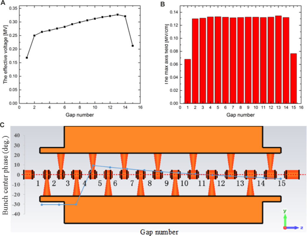
FIGURE 7. (A) Effective voltage, (B) maximum axis field, and (C) phases and electromagnetic structure at each gap center.
Table 5 lists the main parameters of the DTL after optimization. Protons are accelerated from 3.0 MeV to 7.0 MeV with a length of 0.82 m. There are 15 gaps in total: three for −30° of negative phase bunching and 12 for acceleration in the zero phase. The simulated beam transmission efficiency is 100%. The estimated RF power dissipation is approximately 180 kW.
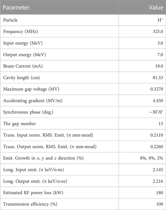
TABLE 5. Main design parameters and the related result of the DTL.
3.3 Multi-particle simulations
Figure 8 shows the output particle distributions of the DTL. Additionally, the figure shows the output energy spread is appropriately 1.5%, and the output phase width is about ±15 deg. Figure 9 displays the transverse and longitudinal beam envelopes containing 99% of the particles along the DTL. The maximum horizontal and vertical envelope sizes are less than 3 mm, which is smaller than the 10 mm radius of the drift tube. In addition, the beam loss due to the nonlinear longitudinal matching is relatively small, which is not an issue for 0.82 m DTL.
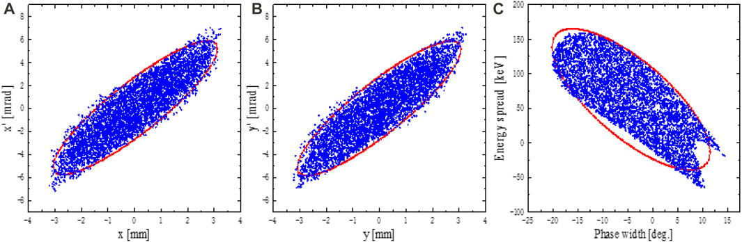
FIGURE 8. Output phase space distribution (A) x-x’, (B) y-y’, (C) phase width vs. energy spread.
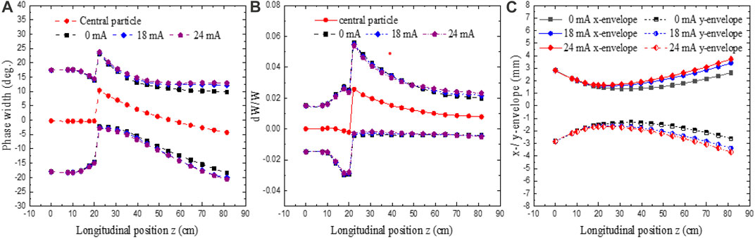
FIGURE 9. Longitudinal envelope evolution: (A) phase width, (B) energy spread, and (C) transverse envelope with beam currents of 0 mA, 18 mA, and 24 mA. The dashed-dotted lines are the beam centroids in the transverse directions.
4 Summary
A 7 MeV compact proton linear injector for a synchrotron-based therapy facility has been proposed to improve the cost performance and accelerate the industrialization process of the proton therapy facility. This injector is mainly composed of an ECR proton source, a LEBT that includes a double electrostatic quadrupole lens, an RFQ accelerator, an external matching section, and an H-type DTL accelerator. Combining the fast-bunching philosophy for RFQ and a modified KONUS beam dynamics principle for IH-DTL, the physical design and multi-particle simulations have been completed. After iterative optimization of RFQ, the parametric resonance has been effectively avoided. The transmission efficiency reaches 98.0% with a length of 3.01 m. Through the external matching section, the beam is injected into the subsequent DTL and accelerated to 7 MeV within 0.82 m. The total length from the exit of ECR to the exit of the DTL is approximately 5 m. The overall multi-particle simulation results show that the beam can be well controlled with a beam transmission efficiency above 95% at 18 mA. The overall average accelerating gradient has reached up to 1.62 MV/m. The transverse and longitudinal normalized rms emittance at the exit of DTL is 0.23 π mmmrad and 2.216 π keV/uns, respectively, which meets the overall design requirements and demands of the subsequent facilities.
Data availability statement
The original contributions presented in the study are included in the article/Supplementary Material, further inquiries can be directed to the corresponding authors.
Author contributions
Study concept and design: JQ, XX, and YP. Physical designs: JQ, NY, and JW. Acquisition of data: JQ, ZH, and YZ. Analysis and interpretation of data: JQ, ZH, and JW. Statistical analysis: JQ and YZ. Supervise and funding the project: WH, YP, and JW. Drafting of the manuscript: JQ, NY, and ZH. All authors contributed to the article and approved the submitted version.
Funding
This work is supported by the National Key Research and Development Program of China (grant number: 2016YFC0105408, 2022YFC2404603, 2022YFC2404600), The Shanghai Committee of Science and Technology Fund (21Y21900200), Xuhui District Artificial Intelligence Medical Hospital Cooperation Project (2021-012) and Key Clinical Specialty Project of Shanghai.
Acknowledgments
We thank LetPub (www.letpub.com) for its linguistic assistance during the preparation of this manuscript.
Conflict of interest
The authors declare that the research was conducted in the absence of any commercial or financial relationships that could be construed as a potential conflict of interest.
Publisher’s note
All claims expressed in this article are solely those of the authors and do not necessarily represent those of their affiliated organizations, or those of the publisher, the editors and the reviewers. Any product that may be evaluated in this article, or claim that may be made by its manufacturer, is not guaranteed or endorsed by the publisher.
References
1. Siegel RL, Miller KD, Fuchs HE, Jemal A. Cancer statistics, 2022. A Cancer J Clinicians (2022) 72(1):7–33. doi:10.3322/caac.21708
2. Xia C, Dong X, Li H, Cao M, Sun D, He S, et al. Cancer statistics in China and United States, 2022: Profiles, trends, and determinants. Chin Med J (Engl) (2022) 135(5):584–90. doi:10.1097/CM9.0000000000002108
3. Xie X, Pu Y, Yang F, Li X, Qiao J, Li D, et al. Design of a 7-MeV APF DTL with robust considerations. Nucl Instr Methods Phys Res Section A: Acc Spectrometers, Detectors, Associated Equipment (2018) 908:49–59. doi:10.1016/j.nima.2018.08.028
4. Li X, Pu Y, Yang F, Xie XC, Gu Q, Qiao J, et al. RF design and study of a 325MHz 7MeV APF IH-DTL for an injector of a proton medical accelerator. Nucl Sci Tech (2019) 30:135. doi:10.1007/s41365-019-0657-4
5. Chen T, Li X, Guo M, Kong H, Chen Z, Zhao M, et al. The application of Lynx-2D in proton spot scanning system commissioning. Nucl Tech (2018) 41:50201. doi:10.11889/j.0253-3219.2018.hjs.41.050201
6. Ge Y, Yin C, Li Z. Optimization design of a multilayer ionization chamber. Nucl Tech (2019) 42:60202. doi:10.11889/j.0253-3219.2019.hjs.42.060202
7. Han G, Qin W, Liu B. Dynamic magnetic measurements of a Kicker magnet for a proton therapy facility. Nucl Tech (2020) 43:10201. doi:10.11889/j.0253-3219.2020.hjs.43.010201
8. Fang S, Guan X, Tang J, Yuan C, Chang-Dong D, Hai-Yi D, et al. Atpf - a dedicated proton therapy facility. CHINESE PHYSICS C (2010) 3:383–8. doi:10.1088/1674-1137/34/3/015
9. Zhang C, Guo ZY, Schempp A, Jameson RA, Chen JE, Fang JX, et al. Low-beam-loss design of a compact, high-current deuteron radio frequency quadrupole accelerator[J]. Phys Rev Spec Top Acc Beams (2004) 7(10): 100101. doi:10.1088/10.1103/physrevstab.7.100101
10. Schempp A. A RFQ-decelerator for hitrap. In: 2007 IEEE Particle Accelerator Conference (PAC); June 25-29, 2007; Albuquerque. IEEE (2008).
11. Ratzinger U, Hhnel H, Tiede R, Kaiser J, Almomani A. Combined zero degree structure beam dynamics and applications. Phys Rev Spec Top - Acc Beams (2019) 22(114801):114801. doi:10.1103/PhysRevAccelBeams.22.114801
12. Crandall KR, Wangler TP. PARMTEQ—a beam dynamics code for the RFQ linear accelerator. . In: AIP Conference Proceedings; August 6-11, 2008; Okayama. American Institute of Physics (2008).
13. Duperrier R. Toutatis: A radio frequency quadrupole code. Rev Mod Phys (2000) 3(12):124201. doi:10.1103/PhysRevSTAB.3.124201
14. Tiede R, Clemente G, Podlech H, Ratzinger U, Sauer A, Minaev S. LORASR code development. In: Proceeding of EPAC2006, WEPCH1118; Edingburgh, Scotland (2006).
15. Uriot D, Pichoff N. Status of TraceWin Code. In: Proceedings of IPAC2015, mopwa008; Richmond, VA, USA (2015). doi:10.18429/JACOW-IPAC2015-MOPWA008
17. Stokes RH, Wangler TP, Crandall KR. The radio-frequency quadrupole - a new linear accelerator. IEEE Trans Nucl Sci (1981) 28(3):1999–2003. doi:10.1109/TNS.1981.4331575
18. Kilpatrick WD. Criterion for vacuum sparking designed to include both rf and dc. Rev Sci Instrum (1957) 28(10):824–6. doi:10.1063/1.1715731
19. Ratti A, Ayers J, Doolittle L, DiGennaro R, Gough RA, Hoff M, et al. The SNS RFQ commissioning. In: Proceedings of 21st International Conference, Linac; August 19-23, 2002; Gyeongju (2002).
20. Sui YF, Cao JS, Deng QY, He J, Ma H, Wang L, et al. Overview of Beam Instrumentation for the CADS Injector I Proton Linac[C]. In: Proceeding of IPAC2015; Richmond, VA, USA (2015).
21. Jia-Er C, Zhi-YuShi-Nian GF, Jia-Xun F, Yuan-Rong L, Xue-Qing Y. Studies on RFQ accelerators and its applications. Chin Phys C (2009) 33(10):926–9. doi:10.1088/1674-1137/33/10/019
22. Young LM, Stovall J, Guan WQ, He Y, Li J, Billen JH, et al. Construction Status of the CPHS RFQ at Tsinghua University[J]. In: Proceedings of IPAC (2011).
23. Kronberger M, Küchler D, Lettry J, Midttun Ø, O’Neil M, Paoluzzi M, et al. Commissioning of the new H− source for Linac4. Rev Scientific Instr (2010) 81(2):02A708. doi:10.1063/1.3278587
24. Hhnel H, Ratzinger U, Tiede R. The KONUS IH-DTL proposal for the GSI UNILAC poststripper linac replacement. J Phys Conf (2017) 874(1):012047. doi:10.1088/1742-6596/874/1/012047
25. Tiede R, Ratzinger U, Podlech H, Zhang C, Clemente G. KONUS beam dynamics designs using H-mode cavities. In: Proceeding of Hadron Beam (2008).
26. Iwata Y, Yamada S, Murakami T, Fujimoto T, Fujisawa T, Ogawa H, et al. Alternating-phase-focused IH-DTL for an injector of heavy-ion medical accelerators. Nucl Instr Methods Phys Res Section A, (Accelerators, Spectrometers, Detectors Associated Equipment) (2006) 569(3):685–96. doi:10.1016/j.nima.2006.09.057
Keywords: proton therapy, compact linear injector, 4-vane RFQ, KONUS dynamics, IH-DTL
Citation: Qiao J, Yan N, Huang Z, Zhong Y, Wang J, Xie X, Pu Y and Hu W (2023) Physical design of a compact injector for synchrotron-based proton therapy. Front. Phys. 11:1201158. doi: 10.3389/fphy.2023.1201158
Received: 06 April 2023; Accepted: 16 May 2023;
Published: 01 June 2023.
Edited by:
Kaiwen Li, CAS Ion Medical Technology Co., Ltd., ChinaReviewed by:
Bo Wu, Mevion China, ChinaZhongshan Li, Chinese Academy of Sciences (CAS), China
Kedong Wang, Peking University, China
Copyright © 2023 Qiao, Yan, Huang, Zhong, Wang, Xie, Pu and Hu. This is an open-access article distributed under the terms of the Creative Commons Attribution License (CC BY). The use, distribution or reproduction in other forums is permitted, provided the original author(s) and the copyright owner(s) are credited and that the original publication in this journal is cited, in accordance with accepted academic practice. No use, distribution or reproduction is permitted which does not comply with these terms.
*Correspondence: Xiucui Xie, xiucuixie@sinap.ac.cn; Yuehu Pu, puyuehu@163.com; Weigang Hu, jackhuwg@gmail.com
†ORCID: Jian Qiao, orcid.org/0000-0003-3831-0621; Zike Huang, orcid.org/0000-0002-2285-423X
†These authors have contributed equally to this work and share first authorship