Bruce Lee-Inspired Fluid Antenna System: Six Research Topics and the Potentials for 6G
 Kai-Kit Wong
 Kin-Fai Tong
 Yuanjun Shen1
 - 1Department of Electronic and Electrical Engineering, University College London, London, United Kingdom
- 2School of Information and Communication Engineering, Beijing University of Posts and Telecommunications, Beijing, China
- 3Kuang-Chi Science Limited, Hong Kong, Hong Kong SAR, China
While 5G is tasked to transform our lives for the better over the next 10 years, next-generation mobile communications, a.k.a. 6G, will undoubtedly demand even higher energy and spectral efficiencies capable of providing myriads of new services and experience to users everywhere they go. Although our technologies do evolve from one generation to the next, the root of the ambition in mobile communications has always been to ensure reliable performance from an uncertain, fluctuating medium. The previous generations have already seen numerous technologies such as advanced coding and signal processing, resource allocation, and most famously, multiple-input multiple-output to redeem some stability from the wireless medium. Inevitably, 6G will be built upon further disruptive technologies that enable another cycle of revolution. In this article, we examine one emerging technology, referred to as fluid antenna system that represents any software-controllable fluidic, conductive, or dielectric structure that can alter its shape and position to reconfigure the gain, radiation pattern, operating frequency, and other characteristics. Fluid antenna takes inspiration from Bruce Lee's Jeet Kune Do to innovate mobile communication systems design. In Bruce Lee's philosophy, one can imitate water to adapt combat style, whereas fluid antenna exploits the dynamic nature of fluids or switchable pixels to achieve ultimate flexibility for diversity and multiplexing benefits that have been unseen before in mobile devices, and the implication can be transformative. This article discusses the potential of fluid antenna systems for 6G, and in particular, we introduce six research topics in fluid antenna systems that if solved successfully could revolutionize mobile communications network design and optimization. This article intends to stimulate discussion that will help shape the development of 6G technologies.
1 Introduction
1.1 Evolution of Mobile Communications
Mobile communications in the 1980s was a luxurious service for civilians providing the convenience of voice communications over wireless medium for the first time, whereas mobile communications nowadays has become a necessity that links almost everything we do in an unimaginable way to support our day-to-day life, amid the Internet of Everything era (Fettweis, 2014; Miraz et al., 2015). Mobile networks have also shifted from the communication-only regime to the service-centric paradigm which embraces new applications such as mobile edge computing (Shi et al., 2016), wireless power transfer (Lu et al., 2015), security enhancement (Mukherjee et al., 2014), and much more. It is predicted that mobile technologies and services will contribute to 4.8% of the global GDP by 2023 and 5G, the latest edition of mobile communications, will amass €1.8 trillion to the global economy over the next 15 years. The impact report (GSMA, 2020) further pointed out that the mobile industry has provided 30 million jobs globally and driven significant gains toward the UN's 2030 Agenda for Sustainable Development.
After half a century of efforts, we have also witnessed some major evolution in the design of mobile communication networks. For example, the first edition (i.e., 1G) primarily used the received signal-to-noise ratio (SNR) and the carrier-to-interference ratio (CIR), to quantify the fidelity of the received signal with CIR providing a network-wide performance measure in the cellular architecture. Then came the digital revolution in 2G where information began to be digitalized and encoded for data compression and noise and fading immunity. Since then, bit-error-rate, packet error rate, and many other similar metrics have dominated the evaluation of wireless system performance, which focuses on the accuracy of the decoded bits. The rise of turbo codes (Berrou et al., 1993; tenBrink, 2001) and low-density parity-check codes (MacKay, 1999) [also more recently Polar codes in 5G (Arikan, 2009; Richardson and Kudekar, 2018)] mean that realizable codes by the state of the art can close the gap between the achievable rates and the channel ergodic capacity to within a fraction of decibel. A majority of the research efforts therefore then shifted to the achievability of the ergodic capacity and maximization of the spectral efficiency. There are evidently variants such as area spectral efficiency (Alouini and Goldsmith, 1999) that are useful to particularize the regional capacity,1 outage capacity (Goldsmith, 2005) that captures the maximum achievable capacity for a given outage probability, and effective capacity (Wu and Negi, 2003) that computes the capacity using a link-layer model with consideration of queues in the buffer and delay violation probability. Recognizing the fact that the value of information may degrade over time, the age-of-information or information freshness has also appeared in the design of communication systems (Kaul et al., 2011; Costa et al., 2016; Sun et al., 2017). Furthermore, emerging topics also attempt to include secrecy and privacy, which have led to concepts such as secrecy capacity (Wyner, 1975; Leung-Yan-Cheong and Hellman, 1978), k-anonymity, l-diversity, and t-closeness (Bezzi, 2010). For 5G, recent trends also give particular importance to latency in addition to reliability for mission-critical applications (Shariatmadari et al., 2015; Popovski et al., 2018). Further additions and changes are anticipated as our mobile communications networks continue to advance.
With the global effort to fight climate change and the looming of energy crisis, in recent years, world leaders have prioritized to reduce the global energy consumption. One great effort is the Paris Agreement, a legally binding international treaty on climate change, that has the ambition to limit global warming to well below 2°C, compared to preindustrial levels (United Nations, 2015). Recently, the 26th UN Climate Change Conference of the Parties in Glasgow has brought the world together to accelerate action on protecting and restoring critical ecosystems. Under the EU 2030 climate and energy framework, it requires every sector to achieve at least 32.5% improvement in energy efficiency and 40% cuts in greenhouse gas emissions by 2030 (European Commision, 2013). The mobile industry is no exception and required to achieve these goals. This has led to the enormous interest of maximizing the energy efficiency for wireless networks (Auer et al., 2011; Chen et al., 2011; Mahapatra et al., 2016).
In terms of mobile technologies, we have witnessed many pivotal innovations over the past decades. Coding, digital modulation, and routing protocols had marked the beginning of the packet switching era in 2G (Roberts, 1978), while 3G was boosted by the introduction of multiple-input multiple-output (MIMO) (Paulraj and kailath, 1994; Alamouti, 1998; Foschini and Gans, 1998; Tarokh et al., 1998; Zheng and Tse, 2003) and spread spectrum technologies (Hara and Prasad, 1997; Bender et al., 2000), making possible multimedia communications over the air for the first time. Then 4G saw the upgrade from link-based MIMO to multiuser MIMO (Wong et al., 2000; Vishwanath S et al., 2003; Wong et al., 2003; Spencer et al., 2004; Gesbert et al., 2007), which has now evolved into massive MIMO in 5G (Ngo et al., 2013; Larsson et al., 2014). During the same period, interference alignment arose with a bang to revolutionize the way in which interference could be treated (Cadambe and Jafar, 2008). Despite its elegance, however, its complexity has still prohibited its use in wireless networks (Zhao et al., 2016). Another great invention was network coding (Ahlswede et al., 2000; Katti et al., 2008) which has found applications in mobile and peer-to-peer networks and also distributed storage systems (Dimakis et al., 2010). Network coding enables data packets to mix and add information as they roam within a network, and it has been illustrated to significantly improve the throughput and robustness of multi-hop networks. There has also been discussion about how network coding may flourish in 5G under the software-defined networking architecture (Hansen et al., 2015), although challenges remain to be tackled on the vulnerability of network coding to malicious attacks. Indeed, 5G is lifted by network slicing and softwarization, a new network architecture that makes possible the multiplexing of virtualized and independent logical networks on the same physical network infrastructure, which is essential to the delivery of services with different attributes (Foukas et al., 2017).
Undoubtedly, mobile networks over the years have also benefited from the advances in the cellular architecture which began from the stack of tiers of hexagonally shaped cells with different sizes in the pre-4G era to the heterogeneous network architecture with irregularly shaped cell coverage in 4G (Damnjanovic et al., 2011; Cheng et al., 2014). For 5G, network densification is a straightforward way to increase regional capacity, reduce latency, and a natural progression to tackle the coverage problem when moving up the operating frequency bands (Bhushan et al., 2014; Ge et al., 2016). Shortening the communication distance for ensuring line-of-sight (LoS) between the remote radio heads (RRHs) and user equipment (UE) is necessary to benefit from the high-frequency bands. Current developments also see a convergence between small cell technologies and cloud radio access network (C-RAN) to grant small cells the capability of a macro baseband unit at the central office (typically miles away from the RRHs). Furthermore, network densification marries nicely with the notion of edge computing, giving the UE access to supercomputing capability at the network edge (Chang et al., 2018). The Small Cell Forum predicted that by 2025, the total number of 5G base stations (BSs) or multi-mode small cells will exceed 13 million across the globe and the installed base of small cells will reach 70 million (Small Cell Forum, 2020). The prospect of network densification seems bright but the energy footprint of BSs and RRHs is worrying. Recently, there is also the emerging idea of cell-free networking (Ngo et al., 2017) which advocates the use of massive MIMO-like signal processing over an extremely large number of distributed access points or RRHs for enormous capacity gain [in a way similar to BS cooperation in the early days (Gesbert et al., 2010; Irmer et al., 2011)]. The impressive performance, however, comes with a huge increase in the overhead for signal coordination, channel estimation, and optimization.
The benefits of many mobile technologies can be understood using the energy efficiency defined as
where Ptotal denotes the total power consumption including also overhead, Eτ[⋅] denotes the expectation of the input quantity over the time duration τ, which may reflect any latency requirement, and
denotes the area traffic capacity,2 where B is the bandwidth, m is connectivity or node density (which is closely related to the multiplexing gain and the frequency reuse factor of the network), and log 2(1 + SINR) denotes the spectral efficiency with SINR being the signal-to-interference plus noise ratio (SINR) for a typical node (or UE). Evidently, further unification will be needed to incorporate new features such as edge computing, secrecy and privacy, wireless power transfer, etc. Despite this, Eqs. 1 and 2 are often sufficient to illustrate the gains of mobile technologies based on traditional metrics. For instance, coding improves spectral efficiency while multiuser MIMO enhances both the node's spectral efficiency and the connectivity. Additionally, spread spectrum technologies focus on improving the connectivity with an acceptable node's spectral efficiency. Network densification and small cell technologies are also well known to increase the node density at the expense of additional infrastructures. As suggested by Eq. 1, their increased power consumption should be accounted for in order to properly assess their overall performance. On the other hand, C-RAN and cell-free technologies adopt advanced signal processing to allow more aggressive spectrum sharing for improving the node density at the price of increased complexity and overheads.
When compared to 4G, 5G has been motivated to increase the spectral efficiency by three times, reduce the latency by 10 times, increase the connectivity (or connection density) by 10 times, increase the experienced throughput (i.e., peak rates more uniformly) by 10 times, increase the area traffic capacity by 100 times, and increase the network energy efficiency by 100 times (Agiwal et al., 2016). Looking ahead, 6G will certainly pursue to achieve more ambitious key performance indicators (Tariq et al., 2020). Several emerging technologies are being discussed actively for their potential roles in 6G. Below, we discuss some of the hottest technologies briefly and attempt to assess the readiness of these technologies.
1.2 Emerging Technologies and Their Limitations
1.2.1 Millimeter-Wave
The ever-increasing data-rate requirements can be met if we find extra bandwidth; see Eq. (2). This is why the operating frequency bands across the globe have the tendency to be moved up for 5G and beyond systems. Of particular interest is the use of the millimeter-wave (mmWave) bands (e.g., 24.25–27.5 GHz in Europe and China, with China also interested in 37–43.5 GHz; 27.5–28.35 GHz and 37–40 GHz in the United States; potentially 26 GHz in the United Kingdom, etc.) that will allow the deployment of hotspots providing very high throughput. Much discussion about mmWave technologies was carried out leading up to 5G in the early 2000s (Rappaport et al., 2013; Andrews et al., 2014; Boccardi et al., 2014). Such bands are excellent for short-range super-fast data transfers which are suitable for fixed wireless links or covering busy areas such as football stadiums, concert halls, shopping malls, etc., but are problematic in general for mobile coverage.
The much higher frequency band means that 5G has a much shorter range than 4G. A recent report (Hardesty, 2020) finds that despite the efforts to reduce power consumption, a typical 5G BS actually consumes up to twice the power of a 4G BS. China Mobile goes even further and warns that a 5G network would generally need three times more BSs for the same coverage, and a 5G BS has three times the power consumption of a 4G BS. Network densification becomes necessary to combine with mmWave communications to maintain the basic coverage. It was reported by Akdeniz et al. (2014) and Rappaport et al. (2015) that the channel encountered in the mmWave band is much more directional and has a narrow beamwidth. Though this could be advantageous due to the inherent antenna gain or spatial directivity, the performance is susceptible to pointing errors due to the misalignment between the transmitter and the receiver. On the other hand, the directional channel loses the fading characteristics which are normally present in the lower frequency band, for exploitation of spatial multiplexing. Moreover, LoS communications between the BS and UE is also required to obtain a reliable link performance.
Above all, to the operators, the main issue for mmWave technologies is the cost of deployment. The Rigorous Total Cost of Ownership (TCO) analysis in Mobile Experts (2021) demonstrates that an mmWave network remains expensive and 95 5G gNodeB (gNB) units are estimated to cost US$12 million for a 10-year TCO. However, it is possible to reduce the cost to half if the same coverage is provided by 10 gNB units and 60 wired and 60 solar repeaters. It is hopeful that further advances will see the cost drop even more in the future, and large-scale deployments of mmWave technologies for 6G are inevitable.
1.2.2 Intelligent Reflecting Surface
Another emerging idea is to deploy a large surface of a massive number of radiating elements in the environment (e.g., on the facade of a building). The large surface provides a large aperture to capture the radio waves and intelligently redirects them to/from the UE by adapting the reflection coefficients of the radiating elements. This concept is widely referred to as Intelligent Reflecting Surface (IRS) (Liaskos et al., 2018; Basar et al., 2019; Renzo et al., 2019), although it may also come under the names such as large intelligent surface (Hu et al., 2018) or programmable metasurface (Tang et al., 2019; Zheng and Zhang, 2020). Note that the recent Industry Specification Group by the European Standards Organisation ETSI has settled on the name reconfigurable intelligent surface instead (ISG, 2021). The research on IRS took off following the emergence of reconfigurable radiating structures (Hum and Perruisseau-Carrier, 2014) and, more promisingly, digitally coded metamaterials (Cui et al., 2014). A notable advantage of IRS is that it does not need power-hungry power amplifiers that require a dedicated power supply. With advances in low-power electronics and architectures, perpetual IRS operation can even be feasible (Abadal et al., 2020). The use of relatively cheap radiating elements also ensures that an IRS has a relatively low hardware cost which is the main reason for its rise.
IRS represents an exciting paradigm of engineering the radio environment through carefully designed software-controlled metamaterials (referred to as “meta-atoms,” unit cells, or elements) that can alter their electromagnetic (EM) properties to suit the purpose of various communication applications. A recent report (Dai et al., 2020) illustrates that it is possible to achieve a 21.7dBi antenna gain using an IRS with 256 2-bit elements at 2.3 GHz, and a 19.1dBi antenna gain at 28.5 GHz. As such, recently, there is a lot of excitement around the development of IRS, and many believe that it will form a crucial part of 6G.
Since the pioneering work by Han et al. (2019) and Huang et al. (2019), there has been a large body of literature illustrating the tremendous performance gain by a well-optimized IRS. Some considered the presence of LoS between the BS/RRH and UE (Han et al., 2019; Huang et al., 2019), while others used IRS to restore the communication link between them (Wu and Zhang, 2019). With regard to the resource management of mobile networks using IRS, although the emphases in the literature might differ, the work largely focused on the signal processing and optimization of either or both of power allocation and phase shifts of the meta-atoms. Taking advantage of the large number of meta-atoms typically on an IRS, multiuser scenarios are often investigated using IRS to strengthen the channel between a MIMO BS and a group of single-antenna UE (Huang et al., 2020; Wu and Zhang, 2020). Optimizing the design of IRS and the beamforming at the BS jointly is, unfortunately, a very complex affair, and it usually involves successive refinement and iterative procedures (Wu and Zhang, 2020). While deep reinforcement learning offers an interesting alternative (Huang et al., 2020), using trial-and-error interactions to obtain the joint design is hardly a scalable option if the number of elements of the IRS is large, as is typically the case. If multiple IRSs are to be used, their optimization will have to be coordinated to avoid mutual interference. Moreover, further complexity is required to acquire the channel state information (CSI) of the cascaded channels between the BS and UE, which is needed for the joint design of BS beamforming and IRS reflection (Liu H et al., 2020; Wang Z et al., 2020; Zheng et al., 2020; Wei et al., 2021). While IRS is effective in enlarging mobile coverage, it does little to enhance the achievable rate. Recent efforts hence look into the possibility of synergizing non-orthogonal multiple access (NOMA) with IRS (Ding and Vincent Poor, 2020; Mu et al., 2020; Wu and Zhang, 2020), although the added complexities at the UE may be a concern.
According to the state of the art (Dai et al., 2019), a well-designed microstrip-like meta-atom (i.e., each element of an IRS) at 4 GHz has only about 500-MHz bandwidth where there is a maximum of 1.25π phase shift range (much less than 2π) and that the amplitude fluctuation is less than 4dB. Worse, at 4.5 GHz, the phase shift range falls to only π, which greatly impairs the IRS' capability for beamforming. The narrow operating bandwidth of conventional IRS technologies will be a major bottleneck for high-speed communications from the BS to the UE if reflection-based IRS is to be relied on.
1.2.3 Non-Orthogonal Multiple Access
NOMA in its current form was first proposed by Higuchi and Kishiyama (2013) when they exploited successive interference cancellation (SIC) at the UE to enhance the downlink rate of a mobile network. The technique is built upon the information-theoretic foundation which features SIC as part of the capacity-achieving codec at the receivers (Caire and Shamai, 2003; Viswanath P and Tse, 2003; Viswanath S and Tse, 2003). The term “NOMA” was first used by Saito et al. (2013) when the scheme was put to the test by thorough system-level simulations taking into account the link adaptation functionalities of the long-term evolution (LTE) radio interface. It is worth mentioning that a serious discussion of non-orthogonal access, however, can date back to as early as 2006 by (Wang et al., 2006). Ding also popularized NOMA by a sequence of fundamental results in, e.g., (Ding et al., 2014; Ding et al., 2015; Ding et al., 2016). In recent years, NOMA has enjoyed so much growth on the rising importance of massive connectivity for 5G and beyond systems (Ye et al., 2021) and the idea that permits users signals to overlap in the same time–frequency resource block and get separated by SIC, enables aggressive spectrum sharing to increase the network throughput.
The complexity of NOMA, nevertheless, is a major hurdle. While NOMA is often sold as the technology for massive connectivity, ironically, the majority of the work has focused on mixing only two users in the same resource block due to decoding delay and complexity. Note that in NOMA, the weaker users get decoded first and then subtracted from the stronger users for decoding next. This specific decoding order is essential to the overall rate performance. For NOMA with many overlapping users, the decoding delay and complexity can be unbearable. Moreover, NOMA requires multiuser detectors such as SIC, and the overlapping users in NOMA need to be carefully selected, with their transmit powers optimized accordingly. This process is called clustering or user pairing, which requires sophisticated optimization and coordination between the BS and UE. It has been illustrated in Ding et al. (2016) that the amazing performance of NOMA depends on proper user pairing. In Zhu et al. (2019), the optimal user pairing and joint power control solutions were derived in a closed form, but user grouping of more than two users in NOMA was considered to be prohibitively complex and not well understood.
1.2.4 Artificial Intelligence
Machine learning or artificial intelligence (AI) which possesses an uncanny ability to spot hidden correlations, pick out incredibly subtle patterns within oceans of data, and make intelligent decisions is transforming our world for the better at a rapid pace. It has already found numerous applications in wireless networks, from channel estimation for massive MIMO systems (Huang et al., 2018; Wen et al., 2018) to cognitive radios and spectrum sharing (Bkassiny et al., 2013; Li H et al., 2018; Chang et al., 2019), to signal classification (O’Shea et al., 2018), to localization (Wang et al., 2017), to physical layer security (He et al., 2018; Chatterjee et al., 2019; Fang et al., 2019), and to emerging topics such as unmanned aerial vehicular communication systems (Liu et al., 2018, 2019), IRS systems (Liu S et al., 2020; Hu et al., 2021), caching and Internet of Things (IoT) systems (Li X et al., 2018; Tan and Hu, 2018), etc. Machine learning can inject the desperately needed intelligence into 5G and beyond mobile networks, and many examples have been discussed in Alsheikh et al. (2014), Jiang et al. (2017), and Zhang et al. (2019). The importance of machine learning for 6G mobile networks seems indisputable (Strinati et al., 2019; Tang et al., 2020; Tang et al., 2020).
With the C-RAN architecture, the BSs/RRHs can offer cloud services to the UE (Shi et al., 2016; Mao et al., 2017). Edge intelligence is the natural progression of both AI and edge computing and is a marriage of both these technologies. Edge intelligence places AI, more specifically deep learning models, into an edge computing environment to augment the performance of edge computing (Zhao et al., 2019). The limited capacity of backhaul and latency, however, can be a critical issue. To ease the backhaul burden and improve privacy, federated learning has been proposed to facilitate distributed model training from across large-scale UE (Kang et al., 2019; Wang et al., 2019; Yang et al., 2020). Although federated learning could greatly reduce the resources needed for offloading data, how this could be managed at a low energy cost with a large number of UE is not well understood. More importantly, the energy cost does not only include radio transmission between terminals but also the energy consumption for training and inference of the machine learning models at the BS/RRH and UE. In Wang et al. (2020), a detailed analysis of energy efficiency across the different cores of neural network–based machine learning has been presented. Nevertheless, such a detailed energy analysis is missing for a network where federated learning or any distributed learning is employed, not to mention for a mobile network with IRSs assisting the communication to the UE.
1.3 Fluid Antennas and the Opportunities
1.3.1 A Brief History of Multiple-Input Multiple-Output
The emerging technologies discussed above give a lot of positives to the development of 6G, but none of them is expected to replace MIMO. In fact, MIMO is simply irreplaceable. MIMO “creates” bandwidth out from space, independent of the frequency and time domains, and is widely regarded as the most important breakthrough in recent history of mobile technology. Paulraj and Kailath filed a patent in 1994 (Paulraj and Kailath, 1994) describing an apparatus to increase the capacity for wireless systems using distributed transmission and directional reception (DTDR), the setup that captures the essence of MIMO we have today. For this reason, Paulraj is rightfully widely considered as the Father of MIMO. However, MIMO only really came to life after the work by Foschini and Gans (1998), where the Bell Laboratories Layered Space-Time architecture which could realize the capacity benefits of DTDR using SIC was proposed. Remarkably, it was revealed by Foschini and Gans (1998) that the capacity of MIMO scales with the minimum number of antennas at both ends in the asymptotic regime. At the same time, MIMO in the form of space–time codes also emerged to exploit space diversity for error probability reduction (Alamouti, 1998; Tarokh et al., 1998). These early works had triggered waves of MIMO research that had dominated the research community for decades. The benefits of MIMO were formally characterized by Zheng and Tse (2003) using the notion of diversity and multiplexing tradeoff. In particular, the diversity order is defined as
which measures the rate of reduction of the log of the probability of error, Pe, with respect to the increase in the log of the SNR, and the multiplexing gain is defined as
which quantifies the capacity scaling for the link of a single node, with R representing the achievable rate of the MIMO link. Note that Eq. 4 can be extended to multiuser scenarios, and in these cases, R(⋅) in Eq. 4 will denote the overall network capacity and r will then coincide with m in Eq. 2.
Scattering in wireless channels means that each UE has a unique, distinguishable spatial signature that can be exploited by MIMO for multiple access. Research in multiuser MIMO began in 2000 (Wong et al., 2000; Wong et al., 2003), but the field truly took off after the fundamental results in Viswanath and Tse (2003) and Spencer et al. (2004). Since then there has been a paradigm shift from single-user MIMO to multiuser MIMO (Gesbert et al., 2007). By using multiuser MIMO precoding, the network capacity can scale with the number of users without additional bandwidth, offering a solution to massive connectivity. For 4G LTE, MIMO utilizes up to eight downlink and four uplink antennas, while a 5G BS raises the number of antennas to 64 or more. The virtue of the large number of BS antennas enables multiuser MIMO to be achieved using a simple spatial matched filter (Ngo et al., 2013; Larsson et al., 2014). Nonetheless, the number of BS antennas needs to be much greater (e.g., 10 times greater) than the number of the UE sharing the same time–frequency resource block. There is still some way to go for truly massive connectivity.
Although the number of antennas at a BS has been drastically increased in 5G, the number of antennas at a UE remains small
1.3.2 Fluid Antennas: From Fixed Multiple-Input Multiple-Output to Flexible Multiple-Input Multiple-Output
To address this, one may take inspiration from the following quote by Bruce Lee when he described the philosophy of Jeet Kune Do, the martial arts style he created to express his movements in combat3:
“Be like water making its way through cracks. Do not be assertive, but adjust to the object, and you shall find a way round or through it. If nothing within you stays rigid, outward
things will disclose themselves. Empty your mind, be formless. Shapeless, like water. If you put water into a cup, it becomes the cup. You put water into a bottle and it becomes the bottle. You put it in a teapot it becomes the teapot. Now, water can flow or it can crash. Be water, my friend.”
So, what if an antenna can be formless, shapeless like water, and adjusted to the situation?
This is what fluid antenna is all about, which can provide the ultimate reconfigurability and agility for signal and information processing (Wong et al., 2020a). Fluid antenna represents any radiating structure based on software-controllable fluidic, conductive, or dielectric element that can alter their shape, size, and/or position to reconfigure the polarization, operating frequency, radiation pattern, and other characteristics. It may even include designs which involve no fluidic materials (e.g., switchable pixels instead) if they can mimic the agility. Figure 1 illustrates the concept of a possible realization on a handset where conductive fluid is installed on a tube-like structure within which the fluid is free to move, but the shape of the antenna in this example is not changeable. Other types of fluid antennas are possible and will be discussed in Section 2. By enabling the position of the radiating element to shift, as in this example, it allows the UE receiver to browse through the fading envelopes in space for diversity and capacity benefits.
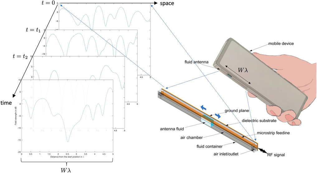
FIGURE 1. An illustration of a handset equipped with a tube-like fluid antenna system and its potential capability in browsing through the various fading envelopes in space. This figure also shows the different fading envelopes a fluid antenna sees over its entire space at different time instants.
To the best knowledge of the authors, the term “fluid antenna” was first used by Kar et al. (2010) when distilled water and chemicals were studied as potential materials for an antenna. Both the transmitting and receiving mode characteristics were investigated for different composition of fluids using both computer simulations and experiments. The most well-known example, however, was probably the seawater antenna Mitsubishi Electric announced a few years ago that demonstrated a radiation efficiency of 70% (Mitsubishi Electric, 2016). Named as “SeaAerial,” the antenna system shoots a column of seawater into the air to create a conductive plume for the transmission and reception of radio waves. Another famous example is the advanced saltwater-based antenna system developed by a research group from Nanjing University of Aeronautics and Astronautics in China that achieved 360-degree beam-steering for frequencies between 334 and 488 MHz (Hampson, 2019; Xing et al., 2019). Despite being less conductive than metals, the fluid-type antennas including also liquid metals, conductive fluids, etc. continue to gather pace, and many reconfigurable fluid antennas have emerged in recent years (Hayes et al., 2012; Morishita et al., 2013; Dey et al., 2016; Borda-Fortuny et al., 2017; Borda-Fortuny et al., 2019; Singh et al., 2019). There is also an emerging idea to use pixel-like electronic switches for designing reconfigurable antennas, and such an idea could be an alternative form of “fluid” antenna (Cetiner et al., 2004; Grau Besoli and De Flaviis, 2011; Chiu et al., 2012; Rodrigo et al., 2014; Song et al., 2014) that could have delay-free switchable positions. Indeed, the last decade has seen numerous advances in the design of fluid- or liquid-based antennas with different reconfigurabilities. A contemporary review on liquid antennas is provided in Huang et al. (2021).
Extending this vision, we can contemplate a future scenario in which flexible antennas based on fluid antenna technologies or similar ones, rather than fixed antennas, are equipped at the UE.4 Additionally, not one but many fluid antennas may be possible at a UE, giving rise to the paradigm of flexible MIMO.
1.3.3 A Hint for Fading-Free, Interference-Free Communications
Despite many explorative efforts in the implementation of various reconfigurable fluid antennas in the antenna community, it was not until the work in Wong et al. (2020a, 2021, 2022) that the characteristics of the fluid antenna were exploited for the design and optimization of wireless communications systems. In the works of (Wong et al., 2020a; Wong et al., 2021), a single-user system in flat fading was considered, where the receiver was equipped with a single-RF = radio frequency chain fluid antenna which could be instantly switched to the best position (referred to as “port”) from a number of closely located fixed ports in a predefined line space. As observed in Figure 1, for each time instant, the fluid antenna system is gifted the ability to browse through the fading envelope and therefore can avoid deep fades by activating the antenna at a desirable position or port, although the resolution will be determined by the number of ports available at the fluid antenna, N. It was illustrated in (Wong et al., 2020b) that the ergodic capacity of a single fluid antenna system can achieve or even exceed that of a maximum-ratio combining (MRC) system with many uncorrelated fixed antennas, if N is sufficiently large. Specifically, for a fluid antenna with half wavelength of space (i.e., W = 0.5), it can achieve an ergodic capacity higher than a five-antenna MRC system, if N ≥ 100. Furthermore (Wong et al., 2021, Theorem 8), has revealed that one fluid antenna could approach zero outage probability for a given finite SNR target, realizing fading-free communications, as N goes to infinity.
Remarkably, the real impact appears in multiuser scenarios where the UE shares the same time–frequency resource for massive connectivity and resolves the interference in the spatial domain by exploiting the ups and downs in their fading envelopes—something that was only possible before by MIMO signal processing to create the peaks and nulls of the fading envelopes with the aid of CSI at the transmitter and/or receiver sides when the transmitter (e.g., the BS in the downlink) has enough antennas. Using fluid antennas at the UE, multiple access is made easier. This can be understood using the example in Figure 2 which shows a downlink setup with the BS using distributed antennas to send signals to two fluid antenna–aided UE. In particular, the BS antenna 1 is dedicated to send the signal to UE 1 while BS antenna 2 transmits to UE 2. No advanced precoding is used at the BS, so obviously the UE are subjected to interference from the unintended BS antenna. The interference at each UE is expected to be resolved by its fluid antenna which oversees the fading envelopes of the intended signal and interference for their exploit. The fact that the fading envelopes of the desired signal and interference are independent suggests that the fluid antenna at a UE is able to find a position (i.e., port) where the interference suffers from a deep fade but the desired signal is acceptable, effectively enabling multiple access naturally without fancy signal processing. In this example, UE 1 and UE 2 can achieve a signal-to-interference ratio (SIR) of 34 dB and 26 dB, respectively, all by its single-RF chain fluid antenna switching to the right port to keep away from the interference and without sophisticated user coordination, crosstalk CSI acquisition, and signal optimization which are normally required if multiuser MIMO or even massive MIMO is adopted. Astonishingly, the intuition for multiple access using fluid antennas (referred to as fluid antenna multiple access (FAMA) in Wong et al., 2022) remains regardless of the number of coexisting users as multiple interferers aggregate naturally to produce a “sum-interference” envelope. In fact, the more the number of users, the deeper and narrower the fade. The interference immunity of a FAMA UE is mainly determined by the spatial resolution of the fluid antenna. An important theoretical result in (Wong et al., 2022, Corollary 1) is that if N goes to infinity (i.e., infinite resolution), the SIR outage probability will go to zero, basically achieving interference-free communications almost surely. Section 2 will review some of the important results of FAMA and discuss their implications.
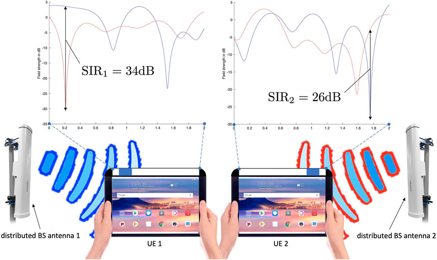
FIGURE 2. A downlink network with the base station (BS) using distributed antennas to communicate with two fluid antenna–aided user equipment (UE). The fading envelopes of the intended signal and interference observed by the fluid antenna at each UE are shown, with an indication that the interference can suppress itself if the fluid antenna chooses an appropriate port for communication, achieving multiple access.
1.3.4 Synergies and Opportunities
Fluid antenna communication systems can improve the spectral efficiency (Wong et al., 2020a), and massively the multiplexing gain (Wong et al., 2022). As a result, the area traffic capacity in Eq. 2 can be enhanced significantly. It is also important to note that these benefits come with no apparent energy and bandwidth overheads for UE coordination, global CSI acquisition, and optimization. Therefore, the network energy efficiency (Eq. 1) should also be greatly improved. There are many exciting opportunities because of fluid antenna technologies. Massive machine-type communication (mMTC) is a key service category for 5G to support extremely high connection density. Massive connectivity with limited spectrum usually means sophisticated network management and coordination among the UE and a great deal of signal processing and resource allocation (e.g., the optimization for NOMA and massive MIMO). Even though massive MIMO can scale up the connectivity considerably without overwhelming the UE, the number of BS antennas is firmly set in the standard and cannot be increased without major hardware and software updates at the BSs. By contrast, fluid antenna offers the possibility of decoupling the mMTC problem into individual UE's optimization of their fluid antennas. That is to say, the network connectivity can grow naturally as the mobile devices advance in their technologies, without impacting on how the network should manage its resources—something that has never been possible before.
On the other hand, the simplicity in signal processing for fluid antenna also appeals to lightweight IoT devices. Many have suggested that 6G will be about connected intelligence which will exploit the wonder in the universe of information from an astronomical number of IoT devices, each with different signal processing capabilities, intelligence, hardware, and battery life. These disparities between the IoT devices make it extremely difficult to have a single communication standard that can fit all. The fact that the way fluid antenna works does not depend on the capability of coexisting devices, greatly simplifies the design of the mobile network. Moreover, user fairness comes naturally because the achievable performance is directly linked to the UE's fluid antenna resolution which dictates its interference immunity. In terms of information security, fluid antenna technologies may also be desirable as multiple users' signals are encouraged to overlap on the same time–frequency resource unit, making it hardly recognizable by eavesdroppers. With imagination, it is envisaged that foldable or bendable antennas can be fit on clothes or textile products. This potentially will enlarge the aperture to collect more radio signals for the UE and concepts such as relaying and/or IRS (in a smaller scale) can be effective to enhance the performance of the UE.
Finally, fluid antenna is a standalone technology and can be easily combined with other technologies. For example, one can still opt to use MIMO beamforming at the BS to focus the signal energies onto the UE directions while the fluid antennas are equipped at the UE for resolving the mutual interference. IRS could also offer a huge number of artificial scatterers to provide the randomness needed in the fading envelopes for exploitation by fluid antennas. In return, fluid antennas could remove the need for complex optimization of the reflection coefficients of the IRS and also liberate the bandwidth of the IRS meta elements which is usually limited by the required range of achievable phase shifts. Evidently, one can still use SIC to separate the users as in NOMA at the UE even if fluid antenna is used. This would be necessary if the resolution of the fluid antenna is limited. With fluid antennas answering the key physical layer questions, AI can focus almost entirely on finding network solutions to deal with situational and contextual conditions. For mmWave, however, the combination with fluid antenna systems could have mixed results. While the increasing bandwidth is expected to bring capacity gain, the directional channel of mmWave will impair the ability of fluid antenna to resolve the interference, which will have to be properly looked at.
1.4 Aim and Scope of This Article
While liquid-based antennas had been researched for over a decade, fluid antenna communication systems research was in a very early stage and the work in Wong et al. (2020b, 2021, 2022) only offers some initial understanding of what fluid antennas may bring to mobile networks. It is fair to say that for fluid antennas to play a role in the delivery of 6G, there are obstacles that need to be overcome satisfactorily. The aim of this article is to present six research topics in fluid antenna systems that, if addressed properly, can become the game changers to pave the way for 6G. We will discuss the potential impacts of each research topic and how the solutions may shape the development of 6G.
The remainder of this article is organized as follows. Section 2 gives a brief survey of conventional fluid antenna technologies that are relevant to the design and optimization of mobile communications networks. Emphasis will be put on two types of fluid antennas: 1) monopole fluid antenna and 2) surface-wave–based fluid antenna. The former is well known for its frequency reconfigurability that can be used for cognitive radios and frequency-hopping communications, while the latter enables a high-definition position-switchable antenna that is capable of obtaining massive diversity and multiplexing gains in a small space. Section 2 will also review several key theoretical results for characterizing the achievable performance of a fluid antenna system in both single and multiuser environments. These results lay the foundations for the six research topics that we will discuss in Section 3. This article is concluded by a short summary of the design specifications useful for antenna experts in Section 4. Finally, Section 5 concludes this article.
2 Fluid Antenna Basics
In this section, we provide an overview of the fluid antenna technology and review some known results that are important in understanding the performance of fluid antennas in wireless communication systems. This section will begin by introducing the hardware architecture and basic components for the two main types of fluid antennas. The first type specializing in frequency reconfigurability follows from the principle of a standard monopole but with an adjustable length, while the second type provides an antenna design that enables shifting of a radiating element over space to obtain spatial diversity in a novel way. This section will be concluded by putting the fluid antenna technology in the context of wireless communications and presenting several key information-theoretic results characterizing the system performance.
2.1 Basic Designs
In the general sense, fluid antennas represent any radiating structure based on software-controllable fluidic, conductive, or dielectric element that can alter their shape, size, and/or position to reconfigure the polarization, operating frequency, radiation pattern, and other performance metrics (Wong et al., 2020b). This contrasts to conventional antennas that are made of solid materials, such as metal wires, plates, dielectric slabs, etc. The beauty of a fluid antenna is that it has no pre-defined form and can be shaped to any desirable form and relocated to adapt to the ever-changing wireless environments. The latter feature empowers itself by the unique capability of escaping from fading or exploiting fading to our advantage.
2.1.1 Fluid Monopole
Figure 3 shows a frequency-agile fluid monopole antenna system where the amount of the radiating fluid inside a tube can be adjusted to control the resonant frequency (Borda-Fortuny et al., 2019). This so-called fluid monopole is particularly suitable for cognitive radio applications in which a device is required to switch the operating frequency over a wideband depending on the access priority and frequency availability (Borda-Fortuny et al., 2018). While a fluid monopole operates more or less like a standard monopole, there can be variants to suit different reconfigurabilities and applications. Regardless, nevertheless, there are four key components: 1) the feeding network for delivering/collecting the RF signal, 2) the fluid serving as the sole or a part of the radiating element, 3) the fluid container and reservoir for holding the fluid, and 4) the pump, feedback mechanism, and the corresponding control unit for changing the antenna performance.
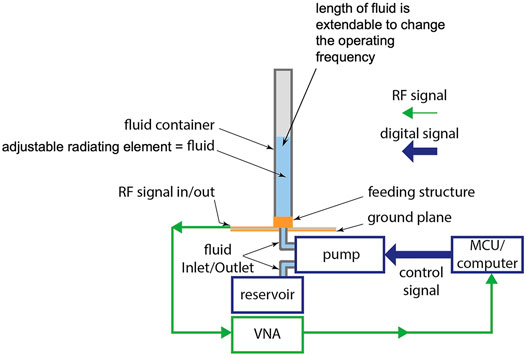
FIGURE 3. The basic components of a fluid monopole.
The feeding network's function is to deliver or receive the RF signal to or from the radiating element. Wideband feeding geometries are required to utilize frequency diversity, and independent performance tuning and leakage-free environment are indispensable. Coupling-fed methods are preferred as they indirectly deliver/collect the RF signal from the radiating element (Li and Luk, 2015; Espley-Jones et al., 2017), while direct-contact feeding methods tend to cause impedance matching problems because they are sensitive to the change of fluid volume in the container (Xing et al., 2015).
The conductive fluid can be chosen as either metallic, for example, mercury and Eutectic Gallium-Indium, or dielectric, such as pure water and ionized solution, radiating element, depending on their electrical properties and implementation constraints (Motovilova and Huang, 2020). Liquid metal radiating element can be EM-modelled like common metals with specific conductivity, whereas fluid antennas using water or ionized solution can be categorized as a dielectric resonator antenna, with the resonant frequencies determined by its size, shape, material, and permittivity (Petosa et al., 1998; Keyrouz and Caratelli, 2016). The term “fluid antenna” was first introduced by Kar et al. (2010), but using fluidic structures for an antenna can be traced back to even earlier by Kosta and Kosta (2004) when mercury was used to make a circular patch liquid microstrip antenna. Since then, evidently, fluid antennas have evolved a lot, and Huang et al. (2021) provide a great survey of the recent advances and offer a bright vision for the future.
Apparently, the fluid needs to be contained when in use or as reserve. Two processes are typically used to assemble the container. The first approach uses polydimethylsiloxane (PDMS) as the material which is a flexible, deformable, and commercially available elastomer. Photolithography is first used to create the microchannels in the PDMS container and then the conductive fluid will flow in to create the radiating elements (Hayes et al., 2012). Another, possibly more practically friendly, method is to use a 3D printer to fabricate the container using resin. Rapid prototyping of fluid antennas using 3D printing technologies has recently been actively researched by Cosker et al. (2017), Su et al. (2017), and Borda-Fortuny et al. (2019).
As shown in Figure 3, a pump that is controlled by a microcontroller is another key component. The pump is adopted for flowing the fluid in and out of the container for controlling the antenna performance. Either micro-pumps (Wang and Fu, 2018) or nano-pumps (Darby et al., 2010) may be used. The microcontroller unit/computer provides the brain of the fluid antenna system to control the fluid flow (e.g., to achieve a prescribed length of the fluid monopole) to tune in to a specific operating frequency.
2.1.2 Surface Wave–Based Position-Flexible Fluid Antenna
Fluid antenna is more than just a frequency-agile antenna and can be designed to counter the unique challenges of wireless communications. Over the decades, communications researchers have been battling to avoid deep fades which come naturally from multipath propagation and control the interference caused by aggressive reuse of the spectrum needed for massive connectivity. As discussed earlier in Section 1.3.2, the fluid antenna offers a new technology to access a collection of fading envelopes in space, which in turn enables the receiver to find and tune in to a spatial window where the signal quality is good. In the single-user case, this means that deep fades can be avoided while for the multiuser scenarios, the antenna can operate at a location where the interference is in a deep fade or the SIR is maximized. Fluid antenna obtains the benefits of MIMO in a completely different way. To perform well, it requires the fluid antenna to have a fine spatial resolution (i.e., large N) to adapt its port (Wong et al., 2021; Wong et al., 2022).
A very high-resolution position-flexible fluid antenna can be achieved using surface wave technologies (Shen et al., 2020; Shen et al., 2021). The technology uses a surface wave to propagate along a dielectric medium that when hitting the fluid radiating element will be diffracted to form the radiation pattern at a given location. As the fluid element shifts its location, the design effectively creates a radiation pattern at the location of the fluid element to capture the received signal via the surface wave. Since the location of the fluid element can be controlled very finely, the design can realize an extremely high spatial resolution. Figure 4A shows the hardware architecture of such surface wave–based fluid antenna. The planar surface wave launcher on the piece of microwave dielectric substrate will excite a surface wave from the RF signal fed at the coplanar waveguide input port. When the surface wave propagating along the PCB substrate is scattered by the fluid radiating element, it results in a space wave, effectively creating a radiation pattern. Figure 4B illustrates this phenomenon as the fluid radiating element shifts its location.
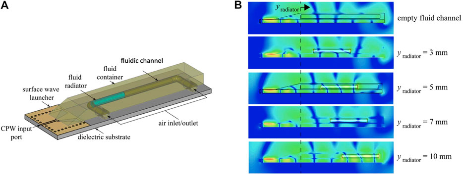
FIGURE 4. (A) A surface wave–based fluid antenna and (B) the E-field distribution of the surface wave–based fluid antenna when the fluid radiating element changes its location.
On the other hand, Figure 5 shows the range of radiation envelopes of the surface-wave fluid antenna at 26 GHz when the fluid radiator moves along the channel. The different angular envelopes are produced when the fluid radiator changes its location inside the channel over the given space. As can be seen, in this example, the fluid antenna can provide a dynamic range of 22dB at around −45° (i.e., the difference between the maximum and minimum achievable). This implies that a fluid antenna can potentially activate a signal null at −45° by switching the fluid radiator at a specific position, which could be a useful feature for interference mitigation. The radiation envelopes at other angular directions can be manipulated similarly by shifting the fluid radiator inside the channel. Evidently, the design will need to be improved in order to possess the full degree of freedom to control the ups and downs of signal envelopes at all angular directions independently. There are other implementation issues that will be discussed in one of the six game-changing topics later. Despite this, the evidence seems encouraging that fluid antenna technologies will innovate the design and optimization of wireless communications systems for years to come.
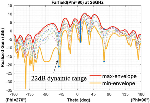
FIGURE 5. The radiation envelopes of the surface wave fluid antenna at different fluid positions at 26 GHz.
2.1.3 Performance Indicators
Like conventional antennas, the performance of a fluid antenna can be characterized in the same way through metrics such as radiation efficiency, gain, radiation pattern, impedance, bandwidth, etc. That said, there are additional indicators that govern the performance of a fluid antenna.
• Performance stability—Some of the fluids used in the antenna design show noticeable changes in performance at different ambient conditions. For example, the operating frequency of water-based and ionized water antennas is sensitive to temperature changes, as the dielectric constant varies with the density of water at different temperatures. By contrast, fluid metals are more stable within their fluid-state temperature. In general, the effects due to atmospheric conditions such as temperature, moisture, pressure, etc. should be minor as the fluid radiator is usually realized in a sealed container. In addition, any frequency de-tuning due to environmental changes can be tackled by the design margin in the operating bandwidth, and changing the resonant dimension of the fluid antenna. In fact, the performance of the fluid antenna under different atmospheric conditions has been extensively investigated in the literature; see, for example, Xing et al. (2012, 2015) and Borda-Fortuny et al. (2019).
• Response time—Reconfigurability of fluid antennas is mainly realized by mobilizing the conductive fluid to a different position (or port) by means of an electronically controlled pump or gravitational force. The time required for the fluid to be moved to the desired position is crucial for communication systems. Considering the use of nano-pumps and the mmWave band, the diameter of the micro-fluidic system for the fluid antenna would be less than 1 mm, and the response time for pumping the air would be in the sub-millisecond range (Rapp, 2016). Such a delay may be small enough for communications of low-mobility UE, but it certainly deserves a proper investigation.
• Implementation difficulty—Fabricating the fluid channels, especially the thin ones, sometimes can be challenging. Fortunately, with the advances in 3D printing technologies, many creative geometries can be realized by waterproof materials. The time and number of processes spending on the fabrication and the peripherals required will be a factor to assess whether a given design is practically feasible.
• Safety—Unlike aluminum, copper, or ceramic used in conventional antenna designs, some of fluid materials, such as oils and solvents, used in fluid antennas might raise safety concerns, as they may be flammable or could have unwanted chemical reactions with the container if not properly designed.
2.2 Information-Theoretic Results
To help understand the roles of fluid antenna technologies, we now focus on the use of statistical models that succinctly describe the communication networks where UE are equipped with a fluid antenna each. We will present some key information-theoretic results from (Wong et al., 2020a; Wong et al., 2021; Wong et al., 2022) that characterize the achievable network performance of fluid antenna–assisted wireless communications. To add value to this article, the results presented here are extensions to the scenario where a 2D fluid antenna surface is used. This represents the fluid antenna system where the fluid radiator is free to roam within a prescribed 2D geometry. To make our models tractable, the fluid radiator is abstracted as an ideal point antenna, ignoring the actual physical dimensions. To help readers follow the mathematical expressions, some important variables and functions are summarized in Table 1.
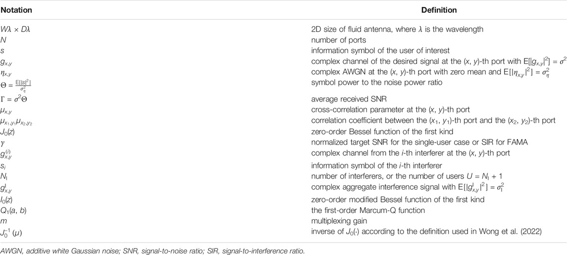
TABLE 1. Notations of important variables and functions.
2.2.1 System Models
2.2.1.1 Single-User Fluid Antenna System
We consider a 2D rectangular surface with dimensions Wλ × Dλ, where λ denotes the wavelength, and it is assumed without loss of generality that W ≤ D. A number of antenna ports are distributed evenly over the surface, and each port represents a location in which the fluid radiator or antenna can be chosen to be activated. It is assumed that only one port can be activated at any given time. For the case where more than one port can be activated at the same time, this represents the fluid MIMO case and will be discussed in Section 3. For ease of exposition, the fluid antenna surface is laid onto a Cartesian coordinate system with a grid distance Δλ for some prescribed Δ. As shown in Figure 6, the ports are located at
where
In what follows, the fluid antenna system has in total (2Nx + 1)(2Ny + 1) ports.
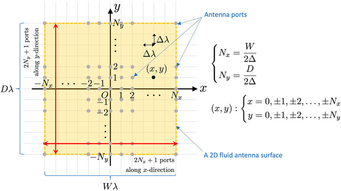
FIGURE 6. The coordinate system that we use to characterize the 2D fluid antenna surface of dimensions Wλ × Dλ, where there are (2Nx + 1)(2Ny + 1) ports for the fluid radiator to be positioned.
The received signal at the (x, y)-th port of a UE of interest can be written as
where s may be the information signal transmitted from the BS, ηx,y is the additive Gaussian noise with zero mean and variance of
with
As the antenna ports can be arbitrarily close to each other, they are spatially correlated. We parameterize the channels by
where ax,y and bx,y are all independent Gaussian random variables with zero mean and variance of
where J0(⋅) is the zero-order Bessel function of the first kind.5 It has been reported in Wong and Tong (2022) that the limited number of parameters {μx,y} would be unable to ensure Eq. 10 for any two ports in the space. It was therefore proposed to set all the parameters equal, i.e., μx,y = μ ∀x, y such that
where the right-hand side of (a) is the average of all possible correlation coefficients for the given ports, and (b) is true when both Nx and Ny become large. By choosing μ according to Eq. 11, the spatial correlation between the ports can be effectively incorporated and μ links with the size parameters D and W.
For the single-user model with a given channel, the average SNR at the (x, y)-th port is given by |gx,y|2Θ and the achievable SNR for the fluid antenna is hence Θ maxx,y{|gx,y|2}, if the maximum port is always selected. An important performance metric is the probability of an outage event:
by considering the channel statistics, where
2.2.1.2 FAMA (Fluid Antenna Multiple Access)
As discussed earlier in Section 1.3.3, fluid antennas can be used to exploit the deep fades of interference for multiple access. When there are NI interferers coexisting in the network, Eq. 7 becomes
where si is the transmitted data from the i-th interferer and
Following from Eq. 9, we can also model
where
The symbol-level SINR at the (x, y)-th port can be expressed as
where (a) ignores the noise with the understanding that the performance is interference-limited. This is particularly true when NI and/or σI is large. It is hypothesized that the fluid antenna will always switch to the port with the maximum of
As such, the following random variable is of interest:
where (a) adopts the assumption that |s| = 1, i.e., constant-modulus modulation, for simplicity. While the channel gain for the desired signal {|gx,y|} and the interference magnitude
2.2.2 Channel Hardening and Diversity Gain
The wireless channel is inherently fluctuating and follows the infamous Rayleigh distribution, resulting in deep fades at times. A known fact for MIMO is that spatial diversity can effectively reduce the spread of the fading envelope (or its variance), which is the well-known channel hardening phenomenon (Hochwald et al., 2004). In the very extreme case where an ultra-massive MIMO is used, the channel will approach to a deterministic channel with no fading at all. One way to demonstrate the effectiveness of fluid antenna is therefore to observe the channel hardening phenomenon of the fading envelope. Figure 7 shows such results illustrating the change of fading envelopes over time for a fluid antenna system with the results of a two-antenna MRC system as the reference. The results indicate that with the ability to select the best fading envelope out of the many over space, the fluid antenna system indeed hardens the channel whose envelope looks much less fluctuating over time, more steady than the two-antenna MRC system. Additionally, the results reveal that with a larger space (20λ versus 5λ), the channel hardening phenomenon looks more obvious.
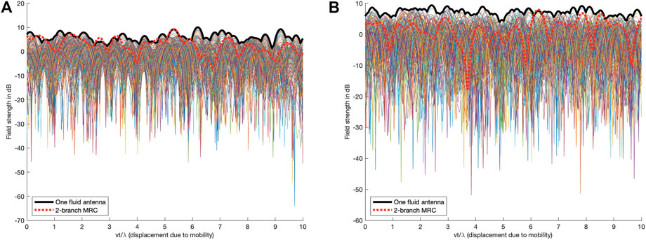
FIGURE 7. Examples of fading envelopes for UE travelling at 30 km/h at 3 GHz when the fluid antenna has 200 ports and a one-dimensional space of (A) 5λ or (B) 20λ.
Precisely, the performance of the fluid antenna system can be characterized by the outage probability,
Corollary 1. The SNR outage probability for the fluid antenna system is given by
where Q1(⋅, ⋅) denotes the first-order Marcum Q-function.
Proof. Obtained directly from (Wong et al., 2021, Theorem 3) and (10).
Corollary 2. The SNR outage probability for the fluid antenna system is upper-bounded by
where κ > 1 and 0 < ϱ < 0.5 are some arbitrary constants.
Proof. Obtained directly from (Wong et al., 2021, Theorem 7) and (10).From this upper bound, we see that the (x, y)-th antenna port contributes to a diversity gain of
Corollary 3. The ergodic capacity of the fluid antenna system is given by
Proof. Obtained directly from (Wong et al., 2020a, Theorem 3) and (10).
2.2.3 Multiple Access and Multiplexing Gain
The real impact of fluid antenna systems comes from their great potential for massive connectivity in the same time–frequency resource block without the requirement for complex coordination and prior signal processing, optimization, and management. As illustrated in Figure 2 and explained in Section 1.3.2, the fluid antenna achieves multiple access in a novel and simple way. Multipath fading naturally performs the magic by letting the envelope of the desired signal and the total interference fade randomly and independently. The fluid antennas at the UE then exploit the spatial window of opportunity where the aggregate interference naturally vanishes to retrieve their desired signals for communications. The keys to FAMA are the independence of the fading envelope of the desired signal and that of the interference, and that the fluid antenna at each UE has a fine spatial resolution (i.e., large N) to locate a desirable port (Wong et al., 2021; Wong et al., 2022). The former can be ensured if the multiuser signals come from different BSs, such as in multicell environments or device-to-device (D2D) applications. In the downlink, it is also possible that each user signal is transmitted from a distributed BS antenna, as considered in Figure 2. On the other hand, the latter relies on technologies such as the surface-wave–based fluid antennas discussed in Section 2.1.2 (Shen et al., 2020; Shen et al., 2021) to browse seemingly freely within the given space to find the right port.
Like the single-user case, we can investigate the achievable performance via the outage probability; this time in terms of the SIR. We can also quantify the capacity scaling of the FAMA network by studying the multiplexing gain, or m in Eq. 2 and more. These results are presented below.
Corollary 4. The SIR outage probability for a FAMA user is given by Eq. 21
where I0(⋅) denotes the zero-order modified Bessel function of the first kind.
Proof. Obtained directly from (Wong et al., 2022, Theorem 1) and (10).
Corollary 5. | The SIR outage probability for a FAMA user is upper-bounded by
Proof. Obtained directly from (Wong et al., 2022, Theorem 2) and (10).An important finding from Corollary 5 is that as Nx, Ny → ∞ (i.e., infinite spatial resolution), the SIR outage probability is shown to go to zero. This confirms the extraordinary interference immunity of the fluid antenna and suggests that truly massive connectivity is possible by overlapping a large number of users over the same time–frequency resource block, and yet, there will be (spatial) moments where the interferences vanish, to be exploited by the fluid antenna at each UE for multiple access. In Wong et al. (2022), it has been reported that hundreds of users can be served at the same channel as long as the resolution of the fluid antenna at each UE is sufficiently high.
Corollary 6. The required number of ports of the fluid antenna surface for a FAMA user to achieve a given multiplexing gain m with a target SIR γ can also be estimated by
Proof. For the model in Wong et al. (2021, 2022), the reference port (0, 0) is auxiliary, which means that the models there actually represent the fluid antenna systems with N − 1 ports, instead of N. Now, we apply Wong et al. (2022, 27 in Theorem 5) by replacing N − 1 by the total number of ports in the 2D surface, (2Nx + 1)(2Ny + 1), to obtain the desired result. Note that the last result on the right in Eq. 23 uses the assumptions that
Corollary 7. The multiplexing gain for the FAMA network satisfies
Proof This is obtained directly from Wong et al. (2022, Eq. 28 in Corollary 2) by replacing N − 1 by (2Nx + 1)(2Ny + 1), which completes the proof.In the above, the multiplexing gain, m, is based on the definition that takes the form:
where (a) computes the ratio of the network capacity and the single-user capacity to find m; (b) assumes that all users are statistically identical and that every user transmits a fixed rate equal to
where
2.2.4 Network Capacity and Energy Efficiency
Network capacity, sometimes referred to as network throughout, is one of the most important performance indicators for mobile communication networks. Capacity, nevertheless, comes with several definitions depending on the emphasis that the network wants to place. Following from the discussion above, if all the FAMA users are statistically identical and they always transmit a fixed rate
where m is characterized by Corollary 7.
On the other hand, one may like to find the maximum achievable rate for a given outage probability,
where
In other words, we have
Furthermore, if each user transmits a very long codeword that can average out the ensemble of its channel, its capacity can be best characterized by ergodic capacity, and the user can adapt its rate to match the capacity. In this case, the ergodic capacity of the FAMA network can be expressed as
where E[⋅] in (a) evaluates the expectation of the input random variable; (b) uses the fact that
We can also define multiplexing gain, m, to work out the capacity scaling in terms of the ergodic capacity. Consequently, we have
where the denominator in (a) corresponds to the ergodic capacity of a single-user channel without fluid antenna; (b) uses Jensen’s inequality; and (c) provides a lower bound for the multiplexing gain.
Following the definition in Eq. 1, if we consider the ergodic capacity as an example, then the energy efficiency of the FAMA network can also be evaluated as
where
3 Six Game-Changing Topics
In this section, we identify six research areas for fluid antenna technologies that can be pivotal in deciding the roles of fluid antenna in 6G mobile communications. Each of the topics, if satisfactorily addressed, is a real opportunity that can potentially revolutionize how future mobile communications evolve.
3.1 Topic 1: Intelligent Reflecting Surface + FAMA
Rightly so, IRS is very much taking over the discussion of 6G wireless communications in recent years. The use of a large surface of passive intelligent reflecting elements is indeed attractive for improving the coverage and enhancing the energy efficiency of the BS greatly when moving up the spectrum for larger bandwidth. This approach is also much more affordable than BS densification. With the goal of getting the best out of IRS, its combination with other technologies is also being studied actively around the world. Despite the overwhelming interest, as discussed in Section 1.2.2, there are legitimate concerns whether IRS can be compatible with the BS technology to deliver the needed performance.
First, the bandwidth of IRS in which there is a sufficient range for phase control is narrow. This is due to the limited bandwidth of the current microstrip or patch design for the unit cells (i.e., meta-atoms) of IRS, which greatly limits the applicability of IRS when the BS is sending a wideband signal to the UE. It is worth pointing out that the current state of the art achieves only a maximum of 1.25π phase shift range, much less than the full degree of freedom 2π for beamforming. This maximum phase shift range also diminishes quickly as the operating frequency changes (Dai et al., 2019). Additionally, even if the phase shift control is to be compromised for larger bandwidth, it is not clear how the beamforming optimization of IRS can cope with 5G orthogonal frequency division multiplexing (OFDM) waveforms such as cyclic prefix OFDM (CP-OFDM) and discrete Fourier transform-spread OFDM (DFT-s-OFDM). The issue is that the phase control for a unit cell at different frequency subcarriers are coupled, and yet, it is known that wireless channels at different frequencies likely differ. Trying to form a single beam that works for a number of subcarriers for a UE is destined to lose its sharpness and be ineffective. The problem worsens if multiple beams are to be formed to point to multiple UE by the IRS. Although the problem can be alleviated if the number of unit cells of the IRS is larger, this comes with a higher cost for estimating the cascaded channels and coordinating the CSI acquisition process. Channel estimation and beamforming optimization are no small tasks, as they involve the BS, the IRS and its many unit cells, and the UE. Moreover, the involved optimization is known to be very complex and not expected to be feasible at the IRS. Thus, it is likely that the optimization will be conducted at the BS with the solution sent to the IRS. Apart from these, the adoption of IRS needs to be carefully planned. While the beamforming of IRS is supposed to boost the signals to the serving UE, this may potentially cause unwanted interference to other UE, similar to intercell interference. Hence, global optimization for multiple IRSs is necessary.
Then how fluid antenna helps overcome the abovementioned obstacles of IRS?
Figure 8 illustrates a vision of using the IRS to provide a large surface of many artificial scatterers for the multiuser signals coming onto the IRS from the BS off to the UE nearby. This is in direct contrast to the conventional approach of using IRS as a smart beamformer. The role of the BS remains the same that its responsibility is to ensure strong signals coming onto the IRS. However, only the CSI between the BS and the IRS would be required and its statistics including the directional information will remain unchanged forever because both the BS and IRS are at fixed locations. With the IRS as massive scatterers, the reflection coefficients (or phase shifts) by the unit cells can be chosen completely randomly. Hence, the multiuser signals will be subjected to an enormous number of multiple paths artificially caused by the unit cells, and the channel conditions will be made highly suitable for FAMA. In this way, as long as the multiuser signals coming onto the IRS have different phase shifts (or are in different subspaces), they will form independent signal envelopes at the UE after encountering the IRS unit cells. This is exactly what FAMA can exploit to enable each UE experience no interference by browsing through the fading envelopes at closely located ports of its fluid antenna. Note that fluid antenna emulates the action of “natural” beamforming by seeking the port that maximizes the SINR because the solution corresponds to the case where the desired signal envelope at the UE peaks by coincidentally aligning the reflected signals from the unit cells.
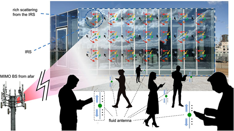
FIGURE 8. Intelligent Reflecting Surface as a large surface of artificial scatterers for FAMA in the downlink.
To see how this works, we can consider the case in which an NT-antenna BS communicates to NI + 1 fluid-antenna UE via an IRS with M reflecting unit cells. Then, the received signal at the (x,y)-th port of the fluid antenna at UE u can be written in a standard FAMA form as
where su represents the information-bearing signal intended for UE u,
where
Following the results in Section 2.2.3, the only requirement for FAMA is that the fading coefficients,
The implications of a positive answer to this problem are disruptive. This means that:
• Optimization of the phase shifts, ϒ, for the IRS is no longer needed, and as the IRS only serves as a source of massive scatterers, a random choice of ϒ suffices. The complexity for estimating the CSI between the IRS and UE and coordinating the channel estimation process is also avoided.
• Eliminating the need for optimizing ϒ also liberates the bandwidth of the IRS because the achievable range for the phase control of the unit cells no longer limits the operational bandwidth of the IRS. In what follows, IRS will always be compatible to any BS wideband technology such as CP-OFDM and DFT-s-OFDM. A single random ϒ would be equally effective for multiple frequency subcarriers if each UE has a dedicated fluid antenna for receiving each subcarrier's signal.
• Including more IRSs in the radio environment always improves the network performance without sophisticated planning and optimization. This is because every IRS effectively provides an additional aperture to collect the radio signals from the BS and bounce them off to the UE near it. It is the fluid antenna at each UE to tune in to the port where “natural” beamforming from the IRSs occurs to see the peak of the desired signal and the disappearance of the interference. All is done without complex optimization of the IRSs, while operating completely passively with minimal energy consumption.
• In the scenario where there is proliferation of IRSs everywhere, it has been suggested that the BSs should be optimized to simply direct the user signals onto the IRSs and the UE get their signals from the IRSs distributed in the environment, while their signal quality is assured by fluid antennas. The advantage is that the beamforming of the BSs to the IRSs can be rather static as they are fixed for the entire time. This will significantly simplify the optimization of the BSs without compromising their performance. Multicell interference can also be handled more easily as the BSs only deal with static IRSs.
• IRS is important for FAMA on very high frequency bands such as mmWave. The supposedly more directional channels in the mmWave band inhibit the fading phenomenon essential for FAMA to shine. The adoption of IRS as a source of massive scatterers therefore helps restore the ups and downs of the fading envelope so that the fluid antenna can exploit for massive connectivity.
3.2 Topic 2: Multiple-Input Multiple-Output + FAMA
FAMA works naturally in D2D environments since the interference signals come from different sources, and the fading envelope of the aggregate interference will be independent of that of the desired signal. For downlink, communications takes place from the BS to a group of UE, and it is expected that the BS has a massive MIMO transceiver. Normally, even with 64 antennas, the BS is not anticipated to serve 64 UE on the same time–frequency resource unit because an excessive number of BS antennas are required to give margin for imperfections when beamforming to the UE. For example, massive MIMO expects to null out the interference by exercising the law of large numbers without performing channel inverses. The opportunity that fluid antenna technologies bring here is that if multiple access is achieved by fluid antennas at the UE as opposed to MIMO beamforming from the BS, then each BS antenna can be used to transmit one user's signal. If the BS antennas are located sufficiently far apart, the multiuser signals coming to a UE will be independent and FAMA will be very effective. As a result, immediately, FAMA can liberate the antennas at the BS to accommodate the maximum number of UE on the same time–frequency resource unit, not to mention the benefits of avoiding the CSI acquisition and beamforming optimization.
Although massive MIMO is a promising technique, this is not a scalable solution. That is to say, one cannot easily upgrade the BSs to incorporate more antennas for higher capacity over night. Such changes are major and will require both hardware and software updates of the BSs, which will demand standardization efforts to address. On the contrary, fluid antenna can be a plug-and-play solution which does not involve hardware changes at the BSs and only requires simple signal processing at the BSs. Presumably, the capacity gain of FAMA can be instantly realized if UE are equipped with fluid antennas and the BSs simply overlap the user signals on the same time–frequency resource block for massive connectivity.
Very importantly, fluid antennas even offer the possibility of overloading MIMO for greater capacity, something that has only been possible using NOMA but at the hefty cost of decoding complexity and delay at the UE as well as network management such as user clustering. Fluid antennas might achieve this without additional efforts at the UE, while the UE remain uncoordinated with each other and each UE still adopts single-user decoding. In spite of the fact that independence of the fading envelopes between the desired signal and the interference ensures performance of FAMA, this does not prohibit FAMA from being used even if the fading envelopes are correlated, as in the overloaded MIMO case when the number of users, U(= NI + 1), is greater than the number of BS antennas, NT, i.e., U > NT.
Figure 9 shows such a scenario where U users are being served by an NT-antenna BS in the downlink and U > NT. This is referred to as an overloaded MIMO situation, which is normally undesirable on a single channel unless multiuser detection such as SIC is used. Each user's signal, say su for UE u, is precoded by a complex vector
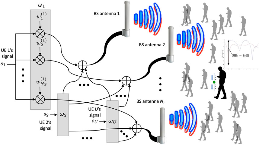
FIGURE 9. Overloading multiple-input multiple-output with FAMA (U > NT) for massive connectivity in the downlink.
Then the received signal at the (x, y)-th port of UE u can be expressed as
where
where
where the expectation is taken as the ensemble average over all the available ports (x, y) : − Nx ≤ x ≤ Nx; − Ny ≤ y ≤ Ny. Note that taking a time average will lead to misleading conditions because the interference information signal on the average will approach to zero, and yet, it does not provide information about the magnitude of the interference experienced at the ports of the fluid antenna at the UE.
Though how to choose the best precoding vectors {ωℓ} is not understood, a possible formulation may be to find {ωℓ} jointly that minimize the sum of the squared correlation coefficients, i.e.,
This, however, may suggest choosing {ωℓ} based on the instantaneous CSI,
Presumably, even if the envelopes of
3.3 Topic 3: Fluid Multiple-Input Multiple-Output
A single fluid antenna at a UE is fabulous but having more than one fluid antennas is potentially even better. The idea is that having multiple fluid antennas gives UE the ability to manipulate the multipath to create ups and downs of the fading envelope before they appear naturally. Assuming a downlink model and nR(>1) fluid antennas at UE u, the received signal at the (x, y)-th port of the j-th fluid antenna can be written similarly as before, i.e.,
where the index j is added to specify the variables corresponding to the j-th fluid antenna. In the above model, MIMO beamforming at the BS is not considered, and each UE's signal is supposed to be transmitted by a dedicated BS antenna, reminiscent of the model in Eq. 13. Given the selected port at the j-th antenna as (xj, yj), the signals,
where
where
Note that the optimization (Eq. 43) is extremely complex as it involves searching the best port combination while the beamforming vector is being optimized. It is fair to say that the beamforming optimization somewhat defeats the beauty of FAMA for simple processing for multiple access.
One way to restore some simplicity of FAMA is to choose the value of
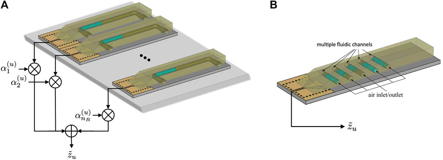
FIGURE 10. Possible implementations for a fluid multiple-input multiple-output (MIMO) system (A) with multiple fluid antennas or (B) with a single fluid MIMO antenna (only single RF chain required).
So far, in the FAMA model, the interference is treated as the instantaneous aggregate interference, which depends on the information signals transmitted by other users at a given time. The analysis in Wong et al. (2022) was based on the symbol-level interference. Specifically, for FAMA to work as it promises, this requires that the fluid antenna switches its port on a symbol-by-symbol basis.6 Obviously, this can be very problematic. Fortunately, a single fluid antenna can handle multiple interferences while selecting the port only once if the fading channels remain unchanged, as opposed to selecting a new port every time the information signals of the interferers change. This will work if the fluid antenna can find a spatial region, wide enough that the channel envelopes of all the interferers fade. This is illustrated in Figure 11, where both three-user and four-user FAMA systems are considered. As can be observed in this figure, it is possible that the interferers fade in a similar region and that the fluid antenna can find a port that suppresses all the interferers independent of their information signals. This will make FAMA practically much more feasible since the chosen port would be valid as long as the channels remain unchanged. Evidently, the likelihood that this occurs will be less and the achievable SIR will be reduced if more interferers are involved. As a result, having multiple fluid antennas or fluid MIMO will help restore the SIR gain.
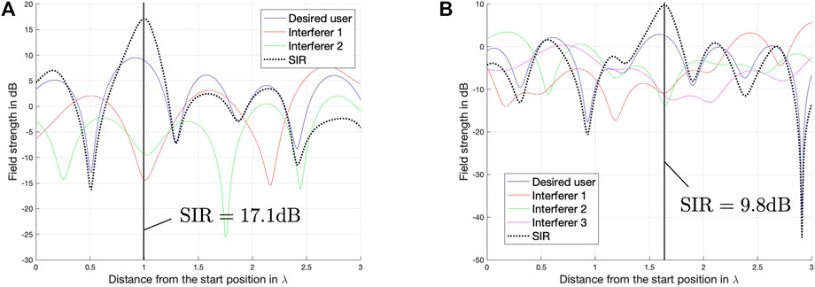
FIGURE 11. Examples of fading envelopes over a FAMA system with (A) three users or (B) four users.
In summary, there are several major questions to answer. First, it is important to find out the interference immunity of FAMA in the case of slow port switching (i.e., switching only when channel changes) via the outage probability performance analysis. While it is true that the interference rejection ability will be discounted due to the lack of port switching, the results in Figure 11 indicate that FAMA still works. It is therefore crucial to investigate the capacity scaling or multiplexing gain of FAMA in this case. It is expected that a larger space of fluid antenna will increase the chance that there is a region in which all the interferers' channels fade for the desired user to exploit. The impact of the size of the fluid antenna on the multiplexing gain should be quantified and give important information on the design of the fluid antenna communication systems. How fluid MIMO can help in this situation is another important subject of research. Evidently, there are issues such as how the SIR or, more generally, SINR can be estimated at the ports for efficient port selection, as well as the best hardware architecture for fluid MIMO. The former issue will be discussed in Topic 4 in Section 3.4 while the implementation issues will be covered in Topic 5 in Section 3.5. Besides these, the joint precoding vector optimization, αu, and port selection, (x, y), in fluid MIMO need to be addressed. Furthermore, it is of great importance to revisit the use of fluid antennas in conjunction with IRS and MIMO when slow port switching and fluid MIMO are adopted.
3.4 Topic 4: Port Selection and Utility Inference
The promising performance of fluid antenna for both single-user and FAMA systems relies on the fact that the best port can be switched to instantly to enjoy favorable communication conditions. Port selection can be classified into two types. The first type requires the fluid antenna only to switch its port according to the channel conditions and is referred to as slow port selection. In this case, the port that has been selected remains unchanged until the channel conditions change. Single-user fluid antenna systems fall into this category, and the SNR is an appropriate metric for port selection. Intriguingly, FAMA systems can also operate using slow port selection (a.k.a. slow FAMA or s-FAMA). If there are only two users sharing the same time–frequency resource unit, then it will only involve two fading envelopes at a given user, one for the desired signal and another from the interferer. The port can then be chosen to maximize the received SINR averaged over the information signals, with the channel fixed. Accommodating more users in slow FAMA is also possible, as discussed earlier in Section 3.3. Accordingly, Eq. 17 becomes
Another type is fast port selection in which the port is re-selected whenever the instantaneous interference signal changes, as is required in Eq. 17. By doing so, the fluid antenna can take advantage of the interference null created naturally by the combination of the fading envelopes and the information signals from the interferers (Wong et al., 2022). By contrast, FAMA with slow port selection hinges on the existence of a region where the fading envelopes of all interferers fall, which is less likely and restricts the achievable SINR (see Figure 11). As a consequence, FAMA with fast port selection, a.k.a. fast FAMA or f-FAMA, is anticipated to perform much better than that with slow port selection.
Before port selection can be performed, the UE needs to have access to the utility at every port. The utility function can be SNR or SINR or others depending on the emphasis of the optimization. To obtain a large performance gain, the number of ports, N (in the one-dimensional case), should be large (e.g., 100s or even 1000s), which may be achieved by the surface wave–based fluid antenna design. The challenge, however, is that it is infeasible to have a large number of utility measurements at the ports. While the difficulty depends on the actual hardware technology of fluid antenna, it is reasonable to consider that only the utility for a very small subset of the ports is made available. An important research direction is thus to develop algorithms that can infer the utility of the unobserved ports based on that of the observed ports, as depicted in Figure 12. Due to the strong correlation among the ports in a tight space, the inference may be achieved using learning methods such as supervised learning over simulated or measurement data and is expected to obtain desirable results. In fact, the UE may not be required to estimate the utility of the unobserved ports and can directly deduce the best port from the known ports using decision-based learning such as the Smart, “Predict and Optimize” approach of Elmachtoub and Grigas (2021).
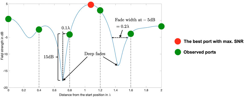
FIGURE 12. Port selection of fluid antenna with only limited observations.
Port selection for FAMA is expectedly more difficult than for single-user fluid antenna systems, regardless of fast or slow port selection. The reason is that the utility function for FAMA usually involves the ratio of two, mostly independent, random quantities (e.g., in SINR). Therefore, it generally has more fluctuations that one can find in a single fading envelope, meaning that FAMA would require more observed ports to infer the best port since the fluctuations break up the correlation between port observations. Also, fast port selection imposes further challenges. As FAMA attempts to observe the instantaneous interference null over the ports at the symbol level, the receiver noise could mislead the UE in the port selection. To alleviate this problem, oversampling will be required to take additional signal samples to average out the noise when estimating the interference null at each symbol duration. On the other hand, estimating the instantaneous SINR at the symbol level is hard. Conventionally, only SINR averaged over the symbols is estimated, which can be done rather straightforwardly by estimating the CSI and knowing the transmit power and noise power. For fast port selection, the UE is asked to estimate the SINR based on one signal sample at each port. A solution to this is to be sought if fast FAMA is to be used for massive connectivity. One possible idea is to develop a differential coding scheme that imposes structures in time so that the UE can extract useful differential information to deduce the SINR at each symbol. All the abovementioned problems should be addressed if fluid antennas need to shine in 6G.
3.5 Topic 5: Implementation of Fluid Antenna and Fluid Multiple-Input Multiple-Output
All the brilliant ideas of the fluid antenna systems are less meaningful if the hardware is not ready. Major efforts are required to have the suitable hardware architecture for the fluid antenna systems, despite the recent successes. There are mainly two approaches for implementing fluid antennas. The first one is liquid-based, like those using liquid metal, ionized solutions or even saltwater, etc. The fluid monopole and surface wave–based fluid antenna discussed below fall into this category, see Section 2.1. The second approach adopts the reconfigurable pixel technology using optimized RF MEMS switches (Cetiner et al., 2004; Grau Besoli and De Flavils, 2011; Chiu et al., 2012; Rodrigo et al., 2014; Song et al., 2014). They have different strengths and weaknesses that need to be thoroughly investigated.
Thus far, the most suitable technology to enable the required feature for the diversity and multiplexing gains appears to be the surface wave–based fluid antenna. It can have an extremely large number of ports, N, and also permit a single RF chain design for fluid MIMO. However, there are several technological challenges that need to be tackled satisfactorily. First, the current design uses one or several tub-like containers to let conductive fluid flow through. While this approach gives great freedom on the possible positions of the fluid radiators, the trails of the positions are fixated by the fluid containers and the shape of each radiating element is predefined as well. The latter affects the natural radiation pattern of each fluid radiator and tends to impose a non-omnidirectional pattern. The containers are also required to be sealed to prevent leakage, which imposes certain limitations on the design. Alternatively, an emerging technology of programmable droplets can be a more attractive approach (Malinowski et al., 2020a; Malinowski et al., 2020b). Figure 13A illustrates a possible schematic of the design where a droplet as the antenna can switch its position by controlling the electric field using the thin conductive lines on top of the dielectric layer (see Figures 13B,C). In a closed configuration (not shown in the figures), the droplet will be grounded between two surfaces where the lower surface is used to apply a controllable voltage with underlying electrodes, while the top plate is a grounding element for the droplet. An immediate advantage is that the use of pump is avoided, miniaturizing the whole design. Instead, electrowetting can be used to mobilize the droplet (Cooney et al., 2006). Both the shape and composition of the droplet play a key role in the radiation pattern and should be optimized. The design in Figure 13A is still based on the surface wave communication principle but the surface wave feeding structure has to be redesigned.
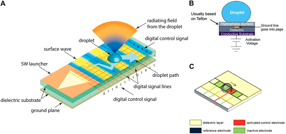
FIGURE 13. A 2D fluid antenna surface using a programmable droplet: (A) the 3D view; (B) the side view; (C) the mobilization of droplets. Note that multiple droplets are possible for a fluid multiple-input multiple-output system.
The greatest weakness of all for the liquid-based fluid antenna is, unfortunately, the response time, as it involves moving a physical object from one point to another in space. While it can be acceptable for s-FAMA if the channels change only very slowly, it is inconceivable to see f-FAMA operate for high-rate communications. To overcome this, reconfigurable pixel technologies are more suitable. This approach is based on an antenna structure consisting of a 2D array of pixels with RF MEMS switches in between that can be turned on or off to achieve reconfigurability. The basic architecture of a reconfigurable antenna surface using patch pixels is shown in Figure 14. In an extreme case where each pixel is to serve as a patch antenna at the operating frequency when on, each pixel then represents a port. This setup, however, limits the number of implementable ports but facilitates easy observation of the utility over the ports.
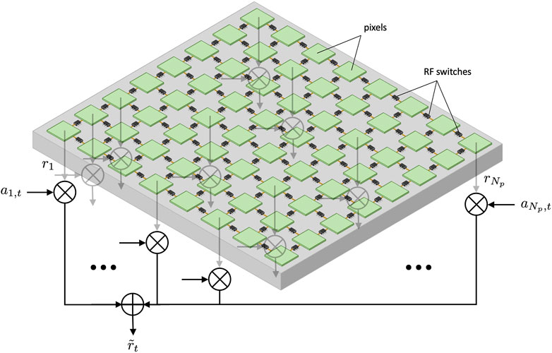
FIGURE 14. A 2D reconfigurable radiating surface of a rectangular grid of pixels connected by RF MEMS switches. The components are not drawn to scale.
We can turn on the pixels one at a time in order to observe the port utilities, but it is also possible to weight and combine the utility signals, {rn}, at all the ports to produce a signal
In the trivial case that T ≥ Np, the estimation of
Overall, pixel-based fluid antennas overcome the problem of response time completely but are limited in the number of ports for selection. It is therefore important to investigate how small we can make the pixels for super-resolution fluid antennas. One specific problem for pixel-based antennas is that even if some pixels are not connected, they will cause mutual coupling to the signals, which is not the case for liquid-based fluid antennas. This will make any signal optimization more difficult to achieve but should not affect much of the performance. Last but not least, it would be interesting to study if liquid-based and pixel-based fluid antenna technologies can be combined together to obtain a better design.
3.6 Topic 6: Low-Latency High-Security FAMA Communications
We conclude this section by briefly discussing the potential of fluid antenna communication systems in terms of latency and security performance. Supporting massive connectivity by using FAMA is one great promise of fluid antenna technologies. Even with s-FAMA, a few users can be overlapped on one time–frequency resource unit with each user switching to their desirable port. The implication is that each user should have a shorter waiting time to access their spectral resource for communications. In the extreme case in which all users are piled onto the same frequency channel, all the users basically access the spectral resource uninterrupted for the entire time (reminiscent of the traditional circuit-switched approach), and the access latency will be zero. In other words, if a UE is equipped with a high-resolution fluid antenna, this UE will have high interference immunity when joining the network, which will encourage the network to give spectrum access to this UE by letting it share the spectrum with the other users without much work for interference control. This means that fluid antenna will contribute directly to reducing the latency of the UE. Evidently, latency also includes decoding latency and any latency associated with preprocessing and network management. In terms of decoding latency, a fluid antenna–assisted UE needs only single-user decoding, and its decoding latency should be much lower than that of SIC for a NOMA user. In addition, FAMA is pretty much user-centric and requires neither crosstalk CSI estimation nor preprocessing of user signals. The BS may have to group the UE with similar interference immunity together when sharing the spectrum and decide on the maximum number of UE on a shared channel. This greatly reduces the burden of the BSs which would have been required for carrying out interference avoidance methods such as massive MIMO, NOMA, etc. A proper analysis is however needed to quantify such benefits.
Security in today's mobile communications technologies is mainly provided by upper layers employing cryptographic techniques, which are largely based on keys or passwords. Without knowing the key, one would need to exhaustively search for the correct key to decrypt the message hidden under the encryption, which should take years to decades given the current computing power. From the practical perspective, this would be sufficiently secure. However, cryptographic security will be easy to break if quantum computing comes to light (DiVincenzo, 1995), smashing the foundation of most modern cryptosystems. Physical layer security techniques therefore have in recent years attracted much attention (Wyner, 1975; Leung-Yan-Cheong and Hellman, 1978; Mukherjee et al., 2014) because they are resilient to quantum computing attack (Shannon, 1949). The idea of physical layer security is that by manipulating the signals in the physical layer in such a way that meaningful detection at an eavesdropper is difficult or even impossible, security is achieved, and it does not depend on the hardness of certain computational problems unlike cryptography. In this sense, FAMA is a security-enhanced technique because user signals are encouraged to overlap, which will make it difficult for the eavesdropper to decode the data from a heavily jammed signal.
According to information theory, for s-FAMA, the secrecy rate for UE u can be found as
where a D2D system model is assumed as an example, and the eavesdropper is considered not to have a fluid antenna.7 In Eq. 47,
in which there is an expectation taken over the information data after the SINR is maximized over the ports. It is expected that the main channel's rate will be boosted by the ability to track the instantaneous interference null on a symbol-by-symbol basis in the f-FAMA setup.
To summarize, fluid antenna–based approaches, particularly FAMA, seem to benefit latency and security on top of capacity gains in mobile communications. That said, little is understood in these areas as fluid antenna technologies are being developed. More should be done in order to quantify the performance gains in a wider context (e.g., a multicell network as a whole) and look at specific scenarios to find out under what conditions the benefits are more prominent. Additionally, it would be interesting to see how much simplifications can be made in the protocol stack using FAMA. It is clear that greater efforts are needed to understand the impacts of fluid antenna systems in terms of latency and security performance.
4 Design Specifications
Before we conclude this article, we include the following table, see Table 2, to list a number of criteria for designing a fluid antenna that can provide some guidelines to antenna engineers.

TABLE 2. Guidelines for designing fluid antennas at UE.
5 Conclusion
In this article, we reviewed the fluid antenna technologies and explored their potentials for 6G mobile communications. Reconfigurable fluid antennas advocate the use of software-controlled conductive fluids or switchable pixels to realize ultimate reconfigurability and flexibility for mobile communications systems, a resemblance to the “Be-Like-Water” combat philosophy in Bruce Lee's Jeet Kune Do. Fluid antennas therefore provide the frequency-agile technology for cognitive radios and more importantly the technology for mobilizing the physical location of a radiating element for diversity and multiplexing gains. This article focused on the latter and reviewed the state-of-the-art technologies for liquid-based antennas before presenting the information-theoretic results of fluid antenna communications systems in the literature. The main contribution of this article is our analysis of the fluid antenna technology in connection with other promising techniques such as MIMO, IRS, mmWave, etc., which have led to the six research topics that if addressed properly, are believed to be disruptive. In summary, it is hopeful that:
• FAMA will greatly simplify the operation and management of IRS for wideband, massive connections by avoiding estimation of the cascaded channels and optimization of the IRS coefficients.
• FAMA will provide the additional dimensions to liberate MIMO at the BSs for accommodating many more users, with the possibility to simplify the optimization of the MIMO antennas as well.
• Fluid MIMO will offer a novel way to realize single RF-chained multiple antennas at the mobile devices and become an effective way to improve interference immunity in FAMA.
• Learning-based methods will empower mobile devices to infer the best port for communications, with very few port observations, for both cases of slow and fast port selection.
• Be it using liquid-based or pixel-based approaches, practically implementable fluid antennas will be ready to provide highly flexible antennas for mobile devices to enjoy high frequency agility and enormous diversity and multiplexing gains with seemingly no response time.
• Fluid antenna technologies will help reduce latency and enhance security for mobile networks.
While the above suggests a bright future, this article has discussed the challenges that have to be tackled. The obstacles are real, and collective efforts from around the world will be required to make fluid antenna–assisted mobile communications a reality. Rightly so, it is too early to predict if sufficient advances in fluid antennas will be made on time to play a part in the development of 6G. It is possible that fluid antenna technologies may come as a booster during the mid-stage of 6G. Note that FAMA is a user-led enhancement and may provide continuous upgrades to the mobile networks as fluid antenna technologies mature. Finally, it is hoped that this article will serve as a catalyst to trigger further research in this thriving area.
Author Contributions
K-KW contributed to the writing of most parts of this article, while K-FT provided expertise in the hardware side of the contents, and YS helped produce the simulation results regarding the surface wave–based fluid antenna. On the other hand, YC contributed to the discussion of some emerging topics in fluid antennas which have formed parts of this article. Finally, YZ provided an important perspective from the industry which has helped highlight the relevance of the article.
Funding
The work reported in this article was supported in part by the Engineering Physical Sciences Research Council (EPSRC) in the UK under grant EP/T015985/1.
Conflict of Interest
Author YZ was employed by the company Kuang-Chi Science Limited.
The remaining authors declare that the research was conducted in the absence of any commercial or financial relationships that could be construed as a potential conflict of interest.
Publisher’s Note
All claims expressed in this article are solely those of the authors and do not necessarily represent those of their affiliated organizations, or those of the publisher, the editors, and the reviewers. Any product that may be evaluated in this article, or claim that may be made by its manufacturer, is not guaranteed or endorsed by the publisher.
Footnotes
1While “capacity” has a precise definition in information theory, which specifies the maximum rate that a channel achieves with error-free communications, admittedly, the term “capacity” has sometimes been used loosely in the literature to simply mean the achievable rate of a communication system.
2To the authors' knowledge, the area traffic capacity definition was first articulated by M.-S. Alouini from King Abdullah University of Science and Technology, Saudi Arabia, in his unified analysis for various enabling technologies for 5G.
3Bruce Lee said this in the television series “Longstreet” which was aired in 1971, for summarizing the whole concept of “Wu Wei” (i.e., doing nothing), of acting effortlessly while exerting effort, or forcefully without using force. This has been the foundation of Jeet Kune Do.
4While it is also possible to have fluid antennas at the BSs, the BSs usually have plenty of space for antennas and the need for fluid antennas is less.
5In Wong et al. (2021, 2022), it was suggested to set μx,y in accordance with Eq. 10 by always referencing to port (0, 0) and assuming μ0,0 = 1. While this can somehow incorporate the spatial correlation into the ports, this could underestimate the impact of correlation on the achievable performance. The condition in Eq. 10 should be applied to any two ports in order to obtain more accurate results. A more detailed treatment is given in Wong et al. (2022).
6This problem is nonexistent if the fluid antenna is used for two-user communications, and port switching is only required when the channel changes.
7Even if the eavesdropper has a fluid antenna, there is no way to know which port provides the desired output without cooperation with the victim.
References
Abadal, S., Cui, T.-J., Low, T., and Georgiou, J. (2020). Programmable Metamaterials for Software-Defined Electromagnetic Control: Circuits, Systems, and Architectures. IEEE J. Emerg. Sel. Top. Circuits Syst. 10 (1), 6–19. doi:10.1109/JETCAS.2020.2976165
Agiwal, M., Roy, A., and Saxena, N. (2016). Next Generation 5G Wireless Networks: A Comprehensive Survey. IEEE Commun. Surv. Tutorials 18 (3), 1617–1655. doi:10.1109/COMST.2016.2532458
Ahlswede, R., Ning Cai, N., Li, S.-Y. R., and Yeung, R. W. (2000). Network Information Flow. IEEE Trans. Inform. Theor. 46 (4), 1204–1216. doi:10.1109/18.850663
Akdeniz, M. R., Liu, Y., Samimi, M. K., Sun, S., Rangan, S., Rappaport, T. S., et al. (2014). Millimeter Wave Channel Modeling and Cellular Capacity Evaluation. IEEE J. Select. Areas Commun. 32 (6), 1164–1179. doi:10.1109/JSAC.2014.2328154
Alamouti, S. M. (1998). A Simple Transmit Diversity Technique for Wireless Communications. IEEE J. Select. Areas Commun. 16 (8), 1451–1458. doi:10.1109/49.730453
Alouini, M.-S., and Goldsmith, A. J. (1999). Area Spectral Efficiency of Cellular mobile Radio Systems. IEEE Trans. Veh. Technol. 48 (4), 1047–1066. doi:10.1109/25.775355
Alsheikh, M. A., Lin, S., Niyato, D., and Tan, H.-P. (2014). Machine Learning in Wireless Sensor Networks: Algorithms, Strategies, and Applications. IEEE Commun. Surv. Tutorials 16 (4), 1996–2018. doi:10.1109/COMST.2014.2320099
Andrews, J. G., Buzzi, S., Choi, W., Hanly, S. V., Lozano, A., Soong, A. C. K., et al. (2014). What Will 5G Be? IEEE J. Select. Areas Commun. 32 (6), 1065–1082. doi:10.1109/JSAC.2014.2328098
Arikan, E. (2009). Channel Polarization: A Method for Constructing Capacity-Achieving Codes for Symmetric Binary-Input Memoryless Channels. IEEE Trans. Inform. Theor. 55 (7), 3051–3073. doi:10.1109/TIT.2009.2021379
Auer, G., Giannini, V., Desset, C., Godor, I., Skillermark, P., Olsson, M., et al. (2011). How Much Energy Is Needed to Run a Wireless Network? IEEE Wireless Commun. 18 (5), 40–49. doi:10.1109/MWC.2011.6056691
Basar, E., Di Renzo, M., De Rosny, J., Debbah, M., Alouini, M.-S., and Zhang, R. (2019). Wireless Communications through Reconfigurable Intelligent Surfaces. IEEE Access 7, 116753–116773. doi:10.1109/ACCESS.2019.2935192
Bender, P., Black, P., Grob, M., Padovani, R., Sindhushyana, N., and Viterbi, A. (2000). CDMA/HDR: A Bandwidth Efficient High Speed Wireless Data Service for Nomadic Users. IEEE Commun. Mag. 38 (7), 70–77. doi:10.1109/35.852034
Berrou, C., Glavieux, A., and Thitimajshima, P. (1993). “Near Shannon Limit Error-Correcting Coding and Decoding: Turbo-Codes. 1,” in Proc. IEEE Int. Conf. Commun. (ICC), Geneva, Switzerland, 23-26 May 1993, 2 1064–1070.
Bezzi, M. (2010). An Information Theoretic Approach for Privacy Metrics. ACM Trans. Data Privacy 3 (3), 199–215. doi:10.5555/2019307.2019309
Bhushan, N., Junyi Li, fnm., Malladi, D., Gilmore, R., Brenner, D., Damnjanovic, A., et al. (2014). Network Densification: The Dominant Theme for Wireless Evolution into 5G. IEEE Commun. Mag. 52 (2), 82–89. doi:10.1109/MCOM.2014.6736747
Bkassiny, M., Li, Y., and Jayaweera, S. K. (2013). A Survey on Machine-Learning Techniques in Cognitive Radios. IEEE Commun. Surv. Tutorials 15 (3), 1136–1159. doi:10.1109/SURV.2012.100412.00017
Boccardi, F., Heath, R. W., Lozano, A., Marzetta, T. L., and Popovski, P. (2014). Five Disruptive Technology Directions for 5G. IEEE Commun. Mag. 52 (2), 74–80. doi:10.1109/MCOM.2014.6736746
Borda-Fortuny, C., Tong, K.-F., Al-Armaghany, A., and Wong, K.-K. (2017). A Low-Cost Fluid Switch for Frequency-Reconfigurable Vivaldi Antenna. Antennas Wirel. Propag. Lett. 16, 3151–3154. doi:10.1109/LAWP.2017.2759580doi:10.1109/lawp.2017.2759580
Borda‐Fortuny, C., Tong, K. F., and Chetty, K. (2018). Low‐cost Mechanism to Reconfigure the Operating Frequency Band of a Vivaldi Antenna for Cognitive Radio and Spectrum Monitoring Applications. IET Microwaves, Antennas & Propagation 12 (5), 779–782. doi:10.1049/iet-map.2017.0731
Borda-Fortuny, C., Cai, L., Tong, K. F., and Wong, K.-K. (2019). Low-cost 3D-Printed Coupling-Fed Frequency Agile Fluidic Monopole Antenna System. IEEE Access 7, 95058–95064. doi:10.1109/ACCESS.2019.2928683
Cadambe, V. R., and Jafar, S. A. (2008). Interference Alignment and Degrees of Freedom of the $K$-User Interference Channel. IEEE Trans. Inform. Theor. 54 (8), 3425–3441. doi:10.1109/TIT.2008.926344
Caire, G., and Shamai, S. (2003). On the Achievable Throughput of a Multiantenna Gaussian Broadcast Channel. IEEE Trans. Inform. Theor. 49 (7), 1691–1706. doi:10.1109/TIT.2003.813523
Cetiner, B. A., Jafarkhani, H., Jiang-Yuan Qian, fnm., Hui Jae Yoo, fnm., Grau, A., and De Flaviis, F. (2004). Multifunctional Reconfigurable MEMS Integrated Antennas for Adaptive MIMO Systems. IEEE Commun. Mag. 42 (12), 62–70. doi:10.1109/MCOM.2004.1367557
Chang, Z., Lei, L., Zhou, Z., Mao, S., and Ristaniemi, T. (2018). Learn to Cache: Machine Learning for Network Edge Caching in the Big Data Era. IEEE Wireless Commun. 25 (3), 28–35. doi:10.1109/MWC.2018.1700317
Chang, H.-H., Song, H., Yi, Y., Zhang, J., He, H., and Liu, L. (2019). Distributive Dynamic Spectrum Access through Deep Reinforcement Learning: A Reservoir Computing-Based Approach. IEEE Internet Things J. 6 (2), 1938–1948. doi:10.1109/JIOT.2018.2872441
Chatterjee, B., Das, D., Maity, S., and Sen, S. (2019). RF-PUF: Enhancing IoT Security through Authentication of Wireless Nodes Using In-Situ Machine Learning. IEEE Internet Things J. 6 (1), 388–398. doi:10.1109/JIOT.2018.2849324
Chen, Y., Zhang, S., Xu, S., and Li, G. Y. (2011). Fundamental Trade-Offs on green Wireless Networks. IEEE Commun. Mag. 49 (6), 30–37. doi:10.1109/MCOM.2011.5783982
Cheng, P., Weily, A. R. W., and Guo, Y. J. (2014). Towards 5th Generation Cellular mobile Networks. J. Telecommun. Digital Economy 2–2. doi:10.18080/jtde.v2n2.328
Chiu, C.-Y., Li, J., Song, S., and Murch, R. D. (2012). Frequency-reconfigurable Pixel Slot Antenna. IEEE Trans. Antennas Propagat. 60 (10), 4921–4924. doi:10.1109/TAP.2012.2207334
Cooney, C. G., Chen, C.-Y., Emerling, M. R., Nadim, A., and Sterling, J. D. (2006). Electrowetting Droplet Microfluidics on a Single Planar Surface. Microfluid Nanofluid 2, 435–446. doi:10.1007/S10404-006-0085-8C
Cosker, M., Lizzi, L., Ferrero, F., Staraj, R., and Ribero, J.-M. (2017). Realization of 3-D Flexible Antennas Using Liquid Metal and Additive Printing Technologies. Antennas Wirel. Propag. Lett. 16, 971–974. doi:10.1109/lawp.2016.2615568
Costa, M., Codreanu, M., and Ephremides, A. (2016). On the Age of Information in Status Update Systems with Packet Management. IEEE Trans. Inform. Theor. 62 (4), 1897–1910. doi:10.1109/TIT.2016.2533395
Cui, T. J., Qi, M. Q., Wan, X., Zhao, J., and Cheng, Q. (2014). Coding Metamaterials, Digital Metamaterials and Programmable Metamaterials. Light Sci. Appl. 3, e218. doi:10.1038/lsa.2014.99
Dai, J. Y., Tang, W. K., Zhao, J., Li, X., Cheng, Q., Ke, J. C., et al. (2019). Wireless Communications through a Simplified Architecture Based on Time‐Domain Digital Coding Metasurface. Adv. Mater. Technol. 4, 1900044. doi:10.1002/admt.201900044
Dai, L., Wang, B., Wang, M., Yang, X., Tan, J., Bi, S., et al. (2020). Reconfigurable Intelligent Surface-Based Wireless Communications: Antenna Design, Prototyping, and Experimental Results. IEEE Access 8, 45913–45923. doi:10.1109/ACCESS.2020.2977772
Damnjanovic, A., Montojo, J., Wei, Y., Ji, T., Luo, T., Vajapeyam, M., et al. (2011). A Survey on 3GPP Heterogeneous Networks. IEEE Wireless Commun. 18 (3), 10–21. doi:10.1109/MWC.2011.5876496
Darby, S. G., Moore, M. R., Friedlander, T. A., Schaffer, D. K., Reiserer, R. S., Wikswo, J. P., et al. (2010). A Metering Rotary Nanopump for Microfluidic Systems. Lab. Chip 10 (23), 3218–3226. doi:10.1039/C0LC00087F
Dey, A., Guldiken, R., and Mumcu, G. (2016). Microfluidically Reconfigured Wideband Frequency-Tunable Liquid-Metal Monopole Antenna. IEEE Trans. Antennas Propagat. 64 (6), 2572–2576. doi:10.1109/TAP.2016.2551358
Dimakis, A. G., Godfrey, P. B., Wu, Y., Wainwright, M. J., and Ramchandran, K. (2010). Network Coding for Distributed Storage Systems. IEEE Trans. Inform. Theor. 56 (9), 4539–4551. doi:10.1109/TIT.2010.2054295
Ding, Z., and Vincent Poor, H. (2020). A Simple Design of IRS-NOMA Transmission. IEEE Commun. Lett. 24 (5), 1119–1123. doi:10.1109/LCOMM.2020.2974196
Ding, Z., Yang, Z., Fan, P., and Poor, H. V. (2014). On the Performance of Non-orthogonal Multiple Access in 5G Systems with Randomly Deployed Users. IEEE Signal. Process. Lett. 21 (12), 1501–1505. doi:10.1109/LSP.2014.2343971
Ding, Z., Peng, M., and Poor, H. V. (2015). Cooperative Non-orthogonal Multiple Access in 5G Systems. IEEE Commun. Lett. 19 (8), 1462–1465. doi:10.1109/LCOMM.2015.2441064
Ding, Z., Fan, P., and Poor, H. V. (2016). Impact of User Pairing on 5G Nonorthogonal Multiple-Access Downlink Transmissions. IEEE Trans. Veh. Technol. 65 (8), 6010–6023. doi:10.1109/TVT.2015.2480766
DiVincenzo, D. P. (1995). Quantum Computation. Science 270 (5234), 255–261. doi:10.1126/science.270.5234.255
Dong, Y., and Itoh, T. (2012). Metamaterial-based Antennas. Proc. IEEE 100 (7), 2271–2285. doi:10.1109/jproc.2012.2187631
Elmachtoub, A. N., and Grigas, P. (2022). Smart "Predict, Then Optimize". Manage. Sci. 68, 9–26. doi:10.1287/mnsc.2020.3922
Espley-Jones, R. J., Tong, F., Dalley, J. E. J., and Langley, D. S. (2017). “Demonstrating a Low Temperature Organic Dense Dielectric Patch Antenna,” in Proc. Loughborough Antennas & Propag. Conf. (LAPC 2017), Loughborough, UK, Nov. 2017, 13–14. doi:10.1049/cp.2017.0296
Fang, H., Wang, X., and Hanzo, L. (2019). Learning-aided Physical Layer Authentication as an Intelligent Process. IEEE Trans. Commun. 67 (3), 2260–2273. doi:10.1109/TCOMM.2018.2881117
Fettweis, G. P. (2014). The Tactile Internet: Applications and Challenges. IEEE Veh. Technol. Mag. 9 (1), 64–70. doi:10.1109/MVT.2013.2295069
Foschini, G. J., and Gans, M. J. (1998). On Limits of Wireless Communications in a Fading Environment when Using Multiple Antennas. Wireless Pers. Commun. 6 (3), 311–335. doi:10.1023/A:1008889222784
Foukas, X., Patounas, G., Elmokashfi, A., and Marina, M. K. (2017). Network Slicing in 5G: Survey and Challenges. IEEE Commun. Mag. 55 (5), 94–100. doi:10.1109/MCOM.2017.1600951
Ge, X., Tu, S., Mao, G., Wang, C.-X., and Han, T. (2016). 5G Ultra-dense Cellular Networks. IEEE Wireless Commun. 23 (1), 72–79. doi:10.1109/MWC.2016.7422408
Gesbert, D., Kountouris, M., Heath, R. W., Chae, C.-b., and Salzer, T. (2007). Shifting the MIMO Paradigm. IEEE Signal. Process. Mag. 24 (5), 36–46. doi:10.1109/MSP.2007.904815
Gesbert, D., Hanly, S., Huang, H., Shamai Shitz, S., Simeone, O., and Yu, W. (2010). Multi-cell MIMO Cooperative Networks: A New Look at Interference. IEEE J. Select. Areas Commun. 28 (9), 1380–1408. doi:10.1109/JSAC.2010.101202
Grau Besoli, A., and De Flaviis, F. (2011). A Multifunctional Reconfigurable Pixeled Antenna Using MEMS Technology on Printed Circuit Board. IEEE Trans. Antennas Propagat. 59 (12), 4413–4424. doi:10.1109/TAP.2011.2165470
Hampson, M. (2019). New Antenna Uses Saltwater and Plastic to Steer Radio Beams. IEEE Spectrum-the Tech. Talk Blog.
Han, Y., Tang, W., Jin, S., Wen, C.-K., and Ma, X. (2019). Large Intelligent Surface-Assisted Wireless Communication Exploiting Statistical CSI. IEEE Trans. Veh. Technol. 68 (8), 8238–8242. doi:10.1109/TVT.2019.2923997
Hansen, J., Lucani, D. E., Krigslund, J., Medard, M., and Fitzek, F. H. P. (2015). Network Coded Software Defined Networking: Enabling 5G Transmission and Storage Networks. IEEE Commun. Mag. 53 (9), 100–107. doi:10.1109/MCOM.2015.7263352
Hara, S., and Prasad, R. (1997). Overview of Multicarrier CDMA. IEEE Commun. Mag. 35 (12), 126–133. doi:10.1109/35.642841
Hardesty, L. (2020). 5G Base Stations Use a Lot More Energy than 4G Base Stations: MTN. Fierce Wireless.
Hayes, G. J., Ju-Hee So, J., Qusba, A., Dickey, M. D., and Lazzi, G. (2012). Flexible Liquid Metal alloy (EGaIn) Microstrip Patch Antenna. IEEE Trans. Antennas Propagat. 60 (5), 2151–2156. doi:10.1109/TAP.2012.2189698
He, D., Liu, C., Quek, T. Q. S., and Wang, H. (2018). Transmit Antenna Selection in MIMO Wiretap Channels: A Machine Learning Approach. IEEE Wireless Commun. Lett. 7 (4), 634–637. doi:10.1109/LWC.2018.2805902
Higuchi, K., and Kishiyama, Y. (2013). “Non-orthogonal Access with Random Beamforming and Intra-beam SIC for Cellular MIMO Downlink,” in IEEE Veh. Technol. Conf. (VTC Fall), NV, USA, 2-5 Sept. 2013 (Las Vegas), 1–5. doi:10.1109/vtcfall.2013.6692307
Hochwald, B. M., Marzetta, T. L., and Tarokh, V. (2004). Multiple-antenna Channel Hardening and its Implications for Rate Feedback and Scheduling. IEEE Trans. Inform. Theor. 50 (9), 1893–1909. doi:10.1109/TIT.2004.833345
Hu, S., Rusek, F., and Edfors, O. (2018). Beyond Massive MIMO: The Potential of Data Transmission with Large Intelligent Surfaces. IEEE Trans. Signal. Process. 66 (10), 2746–2758. doi:10.1109/TSP.2018.2816577
Hu, X., Masouros, C., and Wong, K.-K. (2021). Reconfigurable Intelligent Surface Aided mobile Edge Computing: From Optimization-Based to Location-Only Learning-Based Solutions. IEEE Trans. Commun. 69 (6), 3709–3725. doi:10.1109/TCOMM.2021.3066495
Huang, H., Yang, J., Huang, H., Song, Y., and Gui, G. (2018). Deep Learning for Super-resolution Channel Estimation and DOA Estimation Based Massive MIMO System. IEEE Trans. Veh. Technol. 67 (9), 8549–8560. doi:10.1109/tvt.2018.2851783
Huang, C., Zappone, A., Alexandropoulos, G. C., Debbah, M., and Yuen, C. (2019). Reconfigurable Intelligent Surfaces for Energy Efficiency in Wireless Communication. IEEE Trans. Wireless Commun. 18 (8), 4157–4170. doi:10.1109/TWC.2019.2922609
Huang, C., Mo, R., and Yuen, C. (2020). Reconfigurable Intelligent Surface Assisted Multiuser MISO Systems Exploiting Deep Reinforcement Learning. IEEE J. Select. Areas Commun. 38 (8), 1839–1850. doi:10.1109/JSAC.2020.3000835
Huang, Y., Xing, L., Song, C., Wang, S., and Elhouni, F. (2021). Liquid Antennas: Past, Present and Future. IEEE Open J. Antennas Propag. 2, 473–487. doi:10.1109/OJAP.2021.3069325
Hum, S. V., and Perruisseau-Carrier, J. (2014). Reconfigurable Reflectarrays and Array Lenses for Dynamic Antenna Beam Control: A Review. IEEE Trans. Antennas Propagat. 62 (1), 183–198. doi:10.1109/TAP.2013.2287296
Irmer, R., Droste, H., Marsch, P., Grieger, M., Fettweis, G., Brueck, S., et al. (2011). Coordinated Multipoint: Concepts, Performance, and Field Trial Results. IEEE Commun. Mag. 49 (2), 102–111. doi:10.1109/MCOM.2011.5706317
ISG (2021). Industry Specification Group (ISG) on Reconfigurable Intelligent Surfaces (RIS). [online] Available at: https://www.etsi.org/committee/1966-ris?jjj=1631218280300.
Jiang, C., Zhang, H., Ren, Y., Han, Z., Chen, K.-C., and Hanzo, L. (2017). Machine Learning Paradigms for Next-Generation Wireless Networks. IEEE Wireless Commun. 24 (2), 98–105. doi:10.1109/MWC.2016.1500356WC
Kang, J., Xiong, Z., Niyato, D., Xie, S., and Zhang, J. (2019). Incentive Mechanism for Reliable Federated Learning: A Joint Optimization Approach to Combining Reputation and Contract Theory. IEEE Internet Things J. 6 (6), 10700–10714. doi:10.1109/JIOT.2019.2940820
Kar, S. J., Chakrabarty, A., and Sarkar, B. K. (2010). “Fluid Antennas,” in Proc. IEEE Middle East Conf. Antennas & Propag., Cairo, Egypt, 20-22 Oct. 2010 (MECAP 2010), 1–6. doi:10.1109/MECAP.2010.5724209
Katti, S., Rahul, H., Wenjun Hu, fnm., Katabi, D., Medard, M., and Crowcroft, J. (2008). XORs in the Air: Practical Wireless Network Coding. Ieee/acm Trans. Networking 16 (3), 497–510. doi:10.1109/TNET.2008.923722
Kaul, S., Gruteser, M., Rai, V., and Kenney, J. (2011). “Minimizing Age of Information in Vehicular Networks,” in Proc. IEEE Commun. Soc. Conf. Sensor, Mesh and Ad Hoc Commun. and Netw, Salt Lake City, UT, USA, 27-30 Jun. 2011, 350–358. doi:10.1109/SAHCN.2011.5984917.
Keyrouz, S., and Caratelli, D. (20162016). Dielectric Resonator Antennas: Basic Concepts, Design Guidelines, and Recent Developments at Millimeter-Wave Frequencies. Int. J. Antennas Propagation 2016, 1–20. doi:10.1155/2016/6075680
Kosta, Y., and Kosta, S. (2004). “Liquid Antenna Systems,” in Proc. IEEE Antennas and Propag. Soc. Symp., Monterey, CA, USA, 20-25 Jun. 2004, 3 2392–2395. doi:10.1109/APS.2004.1331854
Larsson, E. G., Edfors, O., Tufvesson, F., and Marzetta, T. L. (2014). Massive MIMO for Next Generation Wireless Systems. IEEE Commun. Mag. 52 (2), 186–195. doi:10.1109/MCOM.2014.6736761
Leung-Yan-Cheong, S., and Hellman, M. (1978). The Gaussian Wire-Tap Channel. IEEE Trans. Inform. Theor. 24 (4), 451–456. doi:10.1109/TIT.1978.1055917
Li, Y., and Luk, K.-M. (2015). A Water Dense Dielectric Patch Antenna. IEEE Access 3, 274–280. doi:10.1109/access.2015.2420103
Li, H., Ota, K., and Dong, M. (2018). Learning IoT in Edge: Deep Learning for the Internet of Things with Edge Computing. IEEE Netw. 32 (1), 96–101. doi:10.1109/MNET.2018.1700202
Li, X., Fang, J., Cheng, W., Duan, H., Chen, Z., and Li, H. (2018). Intelligent Power Control for Spectrum Sharing in Cognitive Radios: A Deep Reinforcement Learning Approach. IEEE Access 6, 25463–25473. doi:10.1109/ACCESS.2018.2831240
Liaskos, C., Nie, S., Tsioliaridou, A., Pitsillides, A., Ioannidis, S., and Akyildiz, I. (2018). A New Wireless Communication Paradigm through Software-Controlled Metasurfaces. IEEE Commun. Mag. 56 (9), 162–169. doi:10.1109/MCOM.2018.1700659
Liu, C. H., Chen, Z., Tang, J., Xu, J., and Piao, C. (2018). Energy-efficient UAV Control for Effective and Fair Communication Coverage: A Deep Reinforcement Learning Approach. IEEE J. Select. Areas Commun. 36 (9), 2059–2070. doi:10.1109/JSAC.2018.2864373
Liu, X., Liu, Y., Chen, Y., and Hanzo, L. (2019). Trajectory Design and Power Control for Multi-UAV Assisted Wireless Networks: A Machine Learning Approach. IEEE Trans. Veh. Technol. 68 (8), 7957–7969. doi:10.1109/TVT.2019.2920284
Liu, H., Yuan, X., and Zhang, Y.-J. A. (2020). Matrix-calibration-based Cascaded Channel Estimation for Reconfigurable Intelligent Surface Assisted Multiuser MIMO. IEEE J. Select. Areas Commun. 38 (11), 2621–2636. doi:10.1109/jsac.2020.3007057
Liu, S., Gao, Z., Zhang, J., Renzo, M. D., and Alouini, M.-S. (2020). Deep Denoising Neural Network Assisted Compressive Channel Estimation for mmWave Intelligent Reflecting Surfaces. IEEE Trans. Veh. Technol. 69 (8), 9223–9228. doi:10.1109/TVT.2020.3005402
Lu, X., Wang, P., Niyato, D., Kim, D. I., and Han, Z. (2015). Wireless Networks with RF Energy Harvesting: A Contemporary Survey. IEEE Commun. Surv. Tutorials 17 (2), 757–789. doi:10.1109/COMST.2014.2368999
MacKay, D. J. C. (1999). Good Error-Correcting Codes Based on Very Sparse Matrices. IEEE Trans. Inform. Theor. 45 (2), 399–431. doi:10.1109/18.748992
Mahapatra, R., Nijsure, Y., Kaddoum, G., Ul Hassan, N., and Yuen, C. (2016). Energy Efficiency Tradeoff Mechanism towards Wireless green Communication: A Survey. IEEE Commun. Surv. Tutorials 18 (1), 686–705. doi:10.1109/comst.2015.2490540
Malinowski, R., Parkin, I. P., and Volpe, G. (2020a). Advances towards Programmable Droplet Transport on Solid Surfaces and its Applications. Chem. Soc. Rev. 49 (22), 7879–7892. doi:10.1039/D0CS00268B
Malinowski, R., Parkin, I. P., and Volpe, G. (2020b). Nonmonotonic Contactless Manipulation of Binary Droplets via Sensing of Localized Vapor Sources on Pristine Substrates. Sci. Adv. 6, 40. doi:10.1126/sciadv.aba3636
Mao, Y., You, C., Zhang, J., Huang, K., and Letaief, K. B. (2017). A Survey on mobile Edge Computing: The Communication Perspective. IEEE Commun. Surv. Tutorials 19 (4), 2322–2358. doi:10.1109/COMST.2017.2745201
Miraz, M. H., Ali, M., Excell, P. S., and Picking, R. (2015). “A Review on Internet of Things (IoT), Internet of Everything (IoE) and Internet of Nano Things (IoNT),” in Proc. Internet Technol. and Appl., Wrexham, UK, 8-11 Sept. 2015, 219–224. doi:10.1109/itecha.2015.7317398
Mitsubishi Electric (2016). Mitsubishi Electric?s SeaAerial Antenna Uses Seawater Plume. [online] Available at: https://www.mitsubishielectric.com.
Morishita, A. M., Kitamura, C. K. Y., Ohta, A. T., and Shiroma, W. A. (2013). A Liquid-Metal Monopole Array with Tunable Frequency, Gain, and Beam Steering. Antennas Wirel. Propag. Lett. 12, 1388–1391. doi:10.1109/LAWP.2013.2286544
Motovilova, E., and Huang, S. Y. (2020). A Review on Reconfigurable Liquid Dielectric Antennas. Materials 13 (8), 1863. doi:10.3390/ma13081863
Mu, X., Liu, Y., Guo, L., Lin, J., and Al-Dhahir, N. (2020). Exploiting Intelligent Reflecting Surfaces in NOMA Networks: Joint Beamforming Optimization. IEEE Trans. Wireless Commun. 19 (10), 6884–6898. doi:10.1109/TWC.2020.3006915
Mukherjee, A., Fakoorian, S. A. A., Huang, J., and Swindlehurst, A. L. (2014). Principles of Physical Layer Security in Multiuser Wireless Networks: A Survey. IEEE Commun. Surv. Tutorials 16 (3), 1550–1573. doi:10.1109/SURV.2014.012314.00178
Hien Quoc Ngo, H. Q., Larsson, E. G., and Marzetta, T. L. (2013). Energy and Spectral Efficiency of Very Large Multiuser MIMO Systems. IEEE Trans. Commun. 61 (4), 1436–1449. doi:10.1109/TCOMM.2013.020413.110848
Ngo, H. Q., Ashikhmin, A., Yang, H., Larsson, E. G., and Marzetta, T. L. (2017). Cell-free Massive MIMO versus Small Cells. IEEE Trans. Wireless Commun. 16 (3), 1834–1850. doi:10.1109/TWC.2017.2655515
O'Shea, T. J., Roy, T., and Clancy, T. C. (2018). Over-the-air Deep Learning Based Radio Signal Classification. IEEE J. Sel. Top. Signal. Process. 12 (1), 168–179. doi:10.1109/JSTSP.2018.2797022
Paulraj, A. J., and Kailath, T. (1994). Increasing Capacity in Wireless Broadcast Systems Using Distributed Transmission/directional Reception (DTDR). US Patent 5 (599A), 345.
Petosa, A., Ittipiboon, A., Antar, Y. M. M., Roscoe, D., and Cuhaci, M. (1998). Recent Advances in Dielectric-Resonator Antenna Technology. IEEE Antennas Propag. Mag. 40 (3), 35–48. doi:10.1109/74.706069
Popovski, P., Nielsen, J. J., Stefanovic, C., Carvalho, E. d., Strom, E., Trillingsgaard, K. F., et al. (2018). Wireless Access for Ultra-reliable Low-Latency Communication: Principles and Building Blocks. IEEE Netw. 32 (2), 16–23. doi:10.1109/MNET.2018.1700258
Rappaport, T. S., Sun, S., Mayzus, R., Zhao, H., Azar, Y., Wang, K., et al. (2013). Millimeter Wave Mobile Communications for 5G Cellular: It Will Work!. IEEE Access 1, 335–349. doi:10.1109/ACCESS.2013.2260813
Rappaport, T. S., MacCartney, G. R., Samimi, M. K., and Sun, S. (2015). Wideband Millimeter-Wave Propagation Measurements and Channel Models for Future Wireless Communication System Design. IEEE Trans. Commun. 63 (9), 3029–3056. doi:10.1109/TCOMM.2015.2434384
Ur Rehman, H., Bellili, F., Mezghani, A., and Hossain, E. (2021). Joint Active and Passive Beamforming Design for IRS-Assisted Multi-User MIMO Systems: A VAMP-Based Approach. IEEE Trans. Commun. 69 (10), 6734–6749. doi:10.1109/TCOMM.2021.3094509
Renzo, M. D., Debbah, M., Phan-Huy, D.-T., Zappone, A., Alouini, M.-S., Yuen, C., et al. (2019). Smart Radio Environments Empowered by Reconfigurable AI Meta-Surfaces: An Idea Whose Time Has Come. J. Wireless Com Netw. 2019, 129. doi:10.1186/s13638-019-1438-9
Richardson, T., and Kudekar, S. (2018). Design of Low-Density Parity Check Codes for 5G New Radio. IEEE Commun. Mag. 56 (3), 28–34. doi:10.1109/MCOM.2018.1700839
Roberts, L. G. (1978). The Evolution of Packet Switching. Proc. IEEE 66 (11), 1307–1313. doi:10.1109/proc.1978.11141
Rodrigo, D., Cetiner, B. A., and Jofre, L. (2014). Frequency, Radiation Pattern and Polarization Reconfigurable Antenna Using a Parasitic Pixel Layer. IEEE Trans. Antennas Propagat. 62 (6), 3422–3427. doi:10.1109/TAP.2014.2314464
Saito, Y., Benjebbour, A., Kishiyama, Y., and Nakamura, T. (2013). “System-level Performance Evaluation of Downlink Non-orthogonal Multiple Access (NOMA),” in Int. Sym. Pers., Indoor, Mobile Radio Commun. (PIMRC), London, UK, 8-11 Sept. 2013, 611–615. doi:10.1109/PIMRC.2013.6666209
Shannon, C. E. (1949). Communication Theory of Secrecy Systems*. The Bell Syst. Tech. J. 28 (4), 656–715. doi:10.1002/j.1538-7305.1949.tb00928.x
Shariatmadari, H., Ratasuk, R., Iraji, S., Laya, A., Taleb, T., Jäntti, R., et al. (2015). Machine-type Communications: Current Status and Future Perspectives toward 5G Systems. IEEE Commun. Mag. 53 (9), 10–17. doi:10.1109/MCOM.2015.7263367
Shen, Y., Tong, K.-F., and Wong, K.-K. (2020). “Beam-steering Surface Wave Fluid Antennas for MIMO Applications,” in Proc. IEEE Asia-Pacific Microwave Conf. (APMC), Hong Kong SAR, China, 8-11 Dec. 2020, 634–636. doi:10.1109/apmc47863.2020.9331647
Shen, Y., Tong, K.-F., and Wong, K.-K. (2021). “Reconfigurable Surface Wave Fluid Antenna for Spatial MIMO Applications,” in Proc. IEEE-APS Topical Conf. Antennas and Propag. in Wireless Commun. (APWC), Honolulu, Hawaii, USA, 9-13 Aug. 2021, 150–152. doi:10.1109/APWC52648.2021.9539785
Shi, W., Cao, J., Zhang, Q., Li, Y., and Xu, L. (2016). Edge Computing: Vision and Challenges. IEEE Internet Things J. 3 (5), 637–646. doi:10.1109/JIOT.2016.2579198
Singh, A., Goode, I., and Saavedra, C. E. (2019). A Multistate Frequency Reconfigurable Monopole Antenna Using Fluidic Channels. Antennas Wirel. Propag. Lett. 18 (5), 856–860. doi:10.1109/LAWP.2019.2903781
Small Cell Forum (2020). SCF Market Status Report July 2020: Small Cells and Digital Transformation.
Song, S., and Murch, R. D. (2014). An Efficient Approach for Optimizing Frequency Reconfigurable Pixel Antennas Using Genetic Algorithms. IEEE Trans. Antennas Propagat. 62 (2), 609–620. doi:10.1109/TAP.2013.2293509
Spencer, Q. H., Swindlehurst, A. L., and Haardt, M. (2004). Zero-forcing Methods for Downlink Spatial Multiplexing in Multiuser MIMO Channels. IEEE Trans. Signal. Process. 52 (2), 461–471. doi:10.1109/TSP.2003.821107
Calvanese Strinati, E., Barbarossa, S., Gonzalez-Jimenez, J. L., Ktenas, D., Cassiau, N., Maret, L., et al. (2019). 6G: The Next Frontier: From Holographic Messaging to Artificial Intelligence Using Subterahertz and Visible Light Communication. IEEE Veh. Technol. Mag. 14 (3), 42–50. doi:10.1109/MVT.2019.2921162
Stüber, G. L. (2002). Principles of Mobile Communication. Second Edition. Kluwer Academic Publishers.
Su, W., Nauroze, S. A., Ryan, B., and Tentzeris, M. M. (2017). “Novel 3D Printed Liquid-Metal-alloy Microfluidics-Based Zigzag and Helical Antennas for Origami Reconfigurable Antenna "trees",” in Proc. 2017 IEEE MTT-S Int. Microwave Symp. (IMS), Honololu, HI, USA, 4-9 Jun. 2017, 1579–1582. doi:10.1109/MWSYM.2017.8058933
Sun, Y., Uysal-Biyikoglu, E., Yates, R. D., Koksal, C. E., and Shroff, N. B. (2017). Update or Wait: How to Keep Your Data Fresh. IEEE Trans. Inform. Theor. 63 (11), 7492–7508. doi:10.1109/TIT.2017.2735804
Tan, L. T., and Hu, R. Q. (2018). Mobility-aware Edge Caching and Computing in Vehicle Networks: A Deep Reinforcement Learning. IEEE Trans. Veh. Technol. 67 (11), 10190–10203. doi:10.1109/TVT.2018.2867191
Tang, W., Dai, J. Y., Chen, M., Li, X., Cheng, Q., Jin, S., et al. (2019). Programmable Metasurface‐based RF Chain‐free 8PSK Wireless Transmitter. Electron. Lett. 55 (7), 417–420. doi:10.1049/el.2019.0400
Tang, F., Kawamoto, Y., Kato, N., and Liu, J. (2020a). Future Intelligent and Secure Vehicular Network toward 6G: Machine-Learning Approaches. Proc. IEEE 108 (2), 292–307. doi:10.1109/JPROC.2019.2954595
Tang, W., Dai, J. Y., Chen, M. Z., Wong, K.-K., Li, X., Zhao, X., et al. (2020b). MIMO Transmission through Reconfigurable Intelligent Surface: System Design, Analysis, and Implementation. IEEE J. Select. Areas Commun. 38 (11), 2683–2699. doi:10.1109/JSAC.2020.3007055
Tariq, F., Khandaker, M. R. A., Wong, K.-K., Imran, M. A., Bennis, M., and Debbah, M. (2020). A Speculative Study on 6G. IEEE Wireless Commun. 27 (4), 118–125. doi:10.1109/mwc.001.1900488
Tarokh, V., Seshadri, N., and Calderbank, A. R. (1998). Space-time Codes for High Data Rate Wireless Communication: Performance Criterion and Code Construction. IEEE Trans. Inform. Theor. 44 (2), 744–765. doi:10.1109/18.661517
tenBrink, S. (2001). Convergence Behavior of Iteratively Decoded Parallel Concatenated Codes. IEEE Trans. Commun. 49 (10), 1727–1737. doi:10.1109/26.957394
United Nations (2015). Paris Agreement. [online] Available: https://unfccc.int/resource/docs/2015/cop21/eng/l09r01.pdf.
Vishwanath, S., Jindal, N., and Goldsmith, A. (2003). Duality, Achievable Rates, and Sum-Rate Capacity of Gaussian MIMO Broadcast Channels. IEEE Trans. Inform. Theor. 49 (10), 2658–2668. doi:10.1109/TIT.2003.817421
Viswanath, P., and Tse, D. N. C. (2003). Sum Capacity of the Vector Gaussian Broadcast Channel and Uplink-Downlink Duality. IEEE Trans. Inform. Theor. 49 (8), 1912–1921. doi:10.1109/TIT.2003.814483
Wang, Y.-N., and Fu, L.-M. (2018). Micropumps and Biomedical Applications - A Review. Microelectronic Eng. 195, 121–138. doi:10.1016/j.mee.2018.04.008
Wang, P., Xiao, J., and Ping, L. (2006). Comparison of Orthogonal and Non-orthogonal Approaches to Future Wireless Cellular Systems. IEEE Veh. Technol. Mag. 1 (3), 4–11. doi:10.1109/MVT.2006.307294
Wang, X., Gao, L., Mao, S., and Pandey, S. (2016). CSI-based Fingerprinting for Indoor Localization: A Deep Learning Approach. IEEE Trans. Veh. Technol. 66 (1), 1. doi:10.1109/TVT.2016.2545523
Wang, S., Tuor, T., Salonidis, T., Leung, K. K., Makaya, C., He, T., et al. (2019). Adaptive Federated Learning in Resource Constrained Edge Computing Systems. IEEE J. Select. Areas Commun. 37 (6), 1205–1221. doi:10.1109/JSAC.2019.2904348
Wang, X., Magno, M., Cavigelli, L., and Benini, L. (2020). FANN-on-MCU: An Open-Source Toolkit for Energy-Efficient Neural Network Inference at the Edge of the Internet of Things. IEEE Internet Things J. 7 (5), 4403–4417. doi:10.1109/JIOT.2020.2976702
Wang, Z., Liu, L., and Cui, S. (2020). Channel Estimation for Intelligent Reflecting Surface Assisted Multiuser Communications: Framework, Algorithms, and Analysis. IEEE Trans. Wireless Commun. 19 (10), 6607–6620. doi:10.1109/twc.2020.3004330
Wei, L., Huang, C., Alexandropoulos, G. C., Yuen, C., Zhang, Z., and Debbah, M. (2021). Channel Estimation for RIS-Empowered Multi-User MISO Wireless Communications. IEEE Trans. Commun. 69 (6), 4144–4157. doi:10.1109/TCOMM.2021.3063236
Wen, C.-K., Shih, W.-T., and Jin, S. (2018). Deep Learning for Massive MIMO CSI Feedback. IEEE Wireless Commun. Lett. 7 (5), 748–751. doi:10.1109/LWC.2018.2818160
Wong, K.-K., and Tong, K.-F. (2021). Fluid Antenna Multiple Access. IEEE Trans. Wireless Commun., 1. doi:10.1109/TWC.2021.3133410
Wong, K. K., Murch, R. D., Cheng, R. S.-K., and Letaief, K. B. (2000). “Optimizing the Spectral Efficiency of Multiuser MIMO Smart Antenna Systems,” in Proc. IEEE Wireless Commun. Netw. Conf. (WCNC), Chicago, IL, USA, 23-28 Sept. 2000, 1 426–430. doi:10.1109/WCNC.2000.904670
Wong, K. K., Murch, R. D., and Letaief, K. B. (2003). A Joint-Channel Diagonalization for Multiuser MIMO Antenna Systems. IEEE Trans. Wireless Commun. 24 (4), 773–786. doi:10.1109/TWC.2003.814347
Wong, K. K., Shojaeifard, A., Tong, K.-F., and Zhang, Y. (2020a). Performance Limits of Fluid Antenna Systems. IEEE Commun. Lett. 24 (11), 2469–2472. doi:10.1109/LCOMM.2020.3006554
Wong, K. K., Tong, K. F., Zhang, Y., and Zhongbin, Z. (2020b). Fluid Antenna System for 6G: When Bruce Lee Inspires Wireless Communications. Electron. Lett. 56 (24), 1288–1290. doi:10.1049/el.2020.2788
Wong, K.-K., Shojaeifard, A., Tong, K.-F., and Zhang, Y. (2021). Fluid Antenna Systems. IEEE Trans. Wireless Commun. 20 (3), 1950–1962. doi:10.1109/TWC.2020.3037595
Wong, K. K., Tong, K. F., Chen, Y., and Zhang, Y. (2022). Closed-form Expressions for Spatial Correlation Parameters for Performance Analysis of Fluid Antenna Systems. Submitted IET Elect. Lett.
Wu, D., and Negi, R. (2003). Effective Capacity: A Wireless Link Model for Support of Quality of Service. IEEE Trans. Wireless Commun. 24 (4), 630–643. doi:10.1109/TWC.2003.814353
Wu, Q., and Zhang, R. (2019). Intelligent Reflecting Surface Enhanced Wireless Network via Joint Active and Passive Beamforming. IEEE Trans. Wireless Commun. 18 (11), 5394–5409. doi:10.1109/TWC.2019.2936025
Wu, Q., and Zhang, R. (2020). Beamforming Optimization for Wireless Network Aided by Intelligent Reflecting Surface with Discrete Phase Shifts. IEEE Trans. Commun. 68 (3), 1838–1851. doi:10.1109/TCOMM.2019.2958916
Wyner, A. D. (1975). The Wire-Tap Channel. Bell Syst. Tech. J. 54 (8), 1355–1387. doi:10.1002/j.1538-7305.1975.tb02040.x
Xing, L., Huang, Y., Alja'afreh, S. S., and Boyes, S. J. (2012). “A Monopole Water Antenna,” in Proc. Loughborough Antennas & Propag. Conf. (LAPC), Loughborough, UK, 12-13 Nov. 2012, 1–4. doi:10.1109/LAPC.2012.6402985
Xing, L., Huang, Y., Shen, Y., Al Ja'afreh, S., Xu, Q., and Alrawashdeh, R. (2015). Further Investigation on Water Antennas. IET Microwaves, Antennas & Propagation 9, 735–741. doi:10.1049/iet-map.2014.0298
Xing, L., Zhu, J., Xu, Q., Yan, D., and Zhao, Y. (2019). A Circular Beam-Steering Antenna with Parasitic Water Reflectors. Antennas Wirel. Propag. Lett. 18 (10), 2140–2144. doi:10.1109/LAWP.2019.2938872
Yang, K., Jiang, T., Shi, Y., and Ding, Z. (2020). Federated Learning via Over-the-air Computation. IEEE Trans. Wireless Commun. 19 (3), 2022–2035. doi:10.1109/TWC.2019.2961673
Ye, N., An, J., and Yu, J. (2021). Deep-learning-enhanced NOMA Transceiver Design for Massive MTC: Challenges, State of the Art, and Future Directions. IEEE Wireless Commun. 28 (4), 66–73. doi:10.1109/MWC.001.2000472
Zhang, C., Patras, P., and Haddadi, H. (2019). Deep Learning in mobile and Wireless Networking: A Survey. IEEE Commun. Surv. Tutorials 21 (3), 2224–2287. doi:10.1109/COMST.2019.2904897
Zhao, N., Yu, F. R., Jin, M., Yan, Q., and Leung, V. C. M. (2016). Interference Alignment and its Applications: A Survey, Research Issues, and Challenges. IEEE Commun. Surv. Tutorials 18 (3), 1779–1803. doi:10.1109/comst.2016.2547440
Zhou, Z., Chen, X., Li, E., Zeng, L., Luo, K., and Zhang, J. (2019). Edge Intelligence: Paving the Last Mile of Artificial Intelligence with Edge Computing. Proc. IEEE 107 (8), 1738–1762. doi:10.1109/JPROC.2019.2918951
Zheng, L., and Tse, D. N. C. (2003). Diversity and Multiplexing: A Fundamental Tradeoff in Multiple-Antenna Channels. IEEE Trans. Inform. Theor. 49 (5), 1073–1096. doi:10.1109/TIT.2003.810646
Zheng, B., and Zhang, R. (2020). Intelligent Reflecting Surface-Enhanced OFDM: Channel Estimation and Reflection Optimization. IEEE Wireless Commun. Lett. 9 (4), 518–522. doi:10.1109/LWC.2019.2961357
Zheng, B., Wu, Q., and Zhang, R. (2020). Intelligent Reflecting Surface-Assisted Multiple Access with User Pairing: NOMA or OMA? IEEE Commun. Lett. 24 (4), 753–757. doi:10.1109/LCOMM.2020.2969870
Zhu, L., Zhang, J., Xiao, Z., Cao, X., and Wu, D. O. (2019). Optimal User Pairing for Downlink Non-orthogonal Multiple Access (NOMA). IEEE Wireless Commun. Lett. 8 (2), 328–331. doi:10.1109/LWC.2018.2853741
Keywords: 6G, B5G, diversity and multiplexing, fluid antenna, massive connectivity, multiple access
Citation: Wong K-, Tong K-, Shen Y, Chen Y and Zhang Y (2022) Bruce Lee-Inspired Fluid Antenna System: Six Research Topics and the Potentials for 6G. Front. Comms. Net 3:853416. doi: 10.3389/frcmn.2022.853416
Received: 12 January 2022; Accepted: 08 February 2022;
Published: 24 March 2022.
Edited by:
Daniel Benevides Da Costa, National Yunlin University of Science and Technology, TaiwanReviewed by:
Shuping Dang, University of Bristol, United KingdomJun Zhang, Hong Kong University of Science and Technology, Hong Kong SAR, China
Copyright © 2022 Wong, Tong, Shen, Chen and Zhang. This is an open-access article distributed under the terms of the Creative Commons Attribution License (CC BY). The use, distribution or reproduction in other forums is permitted, provided the original author(s) and the copyright owner(s) are credited and that the original publication in this journal is cited, in accordance with accepted academic practice. No use, distribution or reproduction is permitted which does not comply with these terms.
*Correspondence: Kai-Kit Wong, kai-kit.wong@ucl.ac.uk