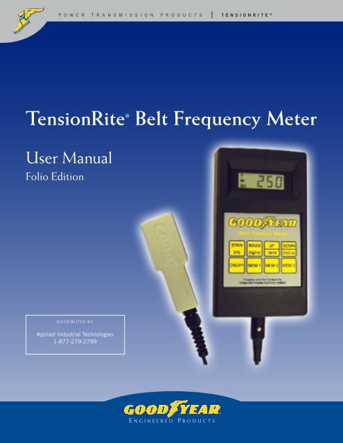
TensionRite® Belt Frequency Meter - Applied Industrial Technologies
TensionRite® Belt Frequency Meter - Applied Industrial Technologies
TensionRite® Belt Frequency Meter - Applied Industrial Technologies

You also want an ePaper? Increase the reach of your titles
YUMPU automatically turns print PDFs into web optimized ePapers that Google loves.
pT oe wn es r i otnrRa intse m ®<br />
i Bs es li ot n f Pr Re OqDuUeCnT cS y M etensionrite t e r<br />
®<br />
TensionRite ® <strong>Belt</strong> <strong>Frequency</strong> <strong>Meter</strong><br />
User Manual<br />
Folio Edition<br />
Distributed By:<br />
<strong>Applied</strong> <strong>Industrial</strong> <strong>Technologies</strong><br />
1-877-279-2799<br />
1
T e n s i o n R i t e ®<br />
B e l t f r e q u e n c y M e t e r<br />
Table of Contents<br />
SECTION<br />
PAGE<br />
1.0 Safety Tips...................................................... 3<br />
2.0 Device Description........................................... 4<br />
3.0 Quick Start...................................................... 5<br />
4.0 Functions<br />
4.1 Keys...................................................... 6<br />
4.2 Audio/Visual Display............................... 8<br />
4.3 Optical Sensor........................................ 9<br />
4.4 Battery Condition.................................... 10<br />
4.5 Charging Batteries.................................. 11<br />
5.0 Setup & Use Procedure.................................... 12<br />
6.0 Operating Tips................................................. 14<br />
7.0 <strong>Meter</strong> Range.................................................... 15<br />
8.0 Calibration<br />
8.1 Spot Check............................................ 16<br />
8.2 Annual Certification................................ 17<br />
9.0 Technical Specifications................................... 18<br />
10.0 Useful Formulas & Conversions......................... 19<br />
Appendix<br />
1.0 <strong>Belt</strong> Mass Constants............................... 20<br />
2.0 Theory of Operation................................ 23<br />
3.0 FAQ’s.................................................... 24<br />
4.0 Tensioning Tables................................... 28<br />
5.0 Limited Warranty.................................... 30<br />
2
T e n s i o n R i t e ®<br />
B e l t f r e q u e n c y M e t e r<br />
1.0 GENERAL SAFETY TIPS<br />
SAFETY FIRST – Read and understand this manual before operating the<br />
TensionRite ® <strong>Meter</strong>.<br />
• Do not drop meter or subject either meter or optical sensor to other sharp impact.<br />
• Do not put water, solvents (including cleaning solutions) or any other liquid on the<br />
unit. Clean meter and sensor with a dry cotton cloth.<br />
• Do not pull on sensor cord. Disconnect sensor from meter by grasping the connector<br />
grip only.<br />
• Do not leave the unit in places that are humid, hot, dust filled or in direct sunlight.<br />
Hint: When the TensionRite ® <strong>Meter</strong> is not to be used for a while, remove the<br />
batteries and store unit in the case provided.<br />
• Do not use your TensionRite ® <strong>Meter</strong> in any explosive environment.<br />
• Do not disassemble or attempt to modify either the meter or the sensing head.<br />
LOCK OUT – TAG OUT<br />
Switch off and isolate any belt drive system prior to taking tension measurements or<br />
attempting any other installation work.<br />
3
T e n s i o n R i t e ®<br />
B e l t f r e q u e n c y M e t e r<br />
2.0 Device Description<br />
LED<br />
Aiming<br />
Beam<br />
Display<br />
Window<br />
see Section 4.2<br />
Key Pad<br />
see Section 4.1<br />
Optical Sensor<br />
see Section 4.3<br />
Cable<br />
Plug-in<br />
The TensionRite ® <strong>Belt</strong> <strong>Frequency</strong> <strong>Meter</strong> from Goodyear Engineered Products is a two<br />
component system consisting of a hand-held meter attached to an optical sensor via<br />
an electronic cable. The sensor uses an infrared beam to detect the vibration of a belt<br />
strand and sends a signal to the meter. (The sensor includes an LED that produces an<br />
orange light beam to help aim the invisible infra-red ray). Comparing this input to the<br />
vibration of a quartz crystal, the meter computes the natural frequency of the belt. The<br />
result is shown in the display window as hertz (oscillations per second). The internal<br />
programming of the meter is also able to report the belt tension in units of force (either<br />
newtons or pounds-force) provided the operator has entered the belt mass and span<br />
length using the manually operated key pad.<br />
The meter operates on four “AA” batteries. Battery life is approximately 20 hours. The<br />
battery compartment is accessible at the back of the meter.<br />
An abridged manual, a tuning fork for checking calibration and a storage case are<br />
included with the complete kit.<br />
4
T e n s i o n R i t e ®<br />
B e l t f r e q u e n c y M e t e r<br />
3.0 Quick Start<br />
Following these simple steps will allow you to measure the vibration frequency of the<br />
belt. This value is independent of span or mass values but is very useful as an index for<br />
belt system maintenance, sometimes the only number you will need. For example, the<br />
MAXIMIZER drive analysis program gives tensioning targets in Hz as well as in force<br />
units (newtons and pounds-force).<br />
For tensioning results in units of force, follow the procedures defined in Section 5.0.<br />
5
T e n s i o n R i t e ®<br />
B e l t f r e q u e n c y M e t e r<br />
4.0 Functions<br />
4.1 Keys<br />
ON/OFF<br />
SPAN<br />
(m)<br />
MASS<br />
(kg/m)<br />
This key switches the meter on or off. If the meter is on and sits idle for<br />
more than 3 minutes, it automatically switches off to preserve battery life.<br />
When the meter is first switched on a battery check is made. See Section<br />
4.4 for a description of the visual and audible low battery signal.<br />
This key is used to enter the belt span length. Hold down the span key and<br />
use the UP or DOWN keys to set the belt span in meters. Releasing the<br />
span key results in an audible beep to indicate the setting has been<br />
accepted. Pressing a MEM(ory) key immediately after releasing the SPAN<br />
key will load the span constant just entered into the appropriate memory<br />
register. Pressing the SPAN key alone shows the current setting.<br />
This key is used to enter the belt mass. Hold down the mass key and use<br />
the UP or DOWN keys to set the belt mass in kilograms/meter (kg/m)).<br />
Releasing the mass key results in an audible beep indicating that the<br />
setting has been accepted. Pressing a MEM(ory) key immediately after<br />
releasing the MASS key will load the mass constant just entered into the<br />
appropriate memory register. Pressing the MASS key alone displays the<br />
current setting.<br />
Important Note:<br />
<strong>Belt</strong> span and belt mass are required entries if tension results in force units (newtons or<br />
pounds-force) are desired. Entries must be in SI units (meters and kg/meter).<br />
UP<br />
(Hz/N)<br />
This key has two functions. The first is to increase either the SPAN or<br />
MASS parameters when used in conjunction with those keys. The second<br />
use is to toggle between the Hz and the newton measurement modes. If<br />
this key is pressed while either the SPAN or MASS keys are being held<br />
down, the number shown in the display window will increase in value. If<br />
only this key is pressed, the display will automatically toggle between<br />
frequency and newtons. The calculation of the force in newtons will be<br />
based upon the mass and span constants currently in the active register.<br />
6
T e n s i o n R i t e ®<br />
B e l t f r e q u e n c y M e t e r<br />
DOWN<br />
(Hz/Lbs)<br />
This key has two functions. The first is to decrease either the SPAN or<br />
MASS parameters when used in conjunction with those keys. The second<br />
use is to toggle between the Hz and the pounds-force measurement modes.<br />
If this key is pressed while either the SPAN or MASS keys are being held<br />
down, the number shown in the display window will decrease in value.<br />
If only this key is pressed, the display will automatically toggle between<br />
frequency and pounds. The calculation of the force in pounds will be based<br />
upon the mass and span constants currently in the active register.<br />
MEM 1<br />
MEM 2<br />
MEM 3<br />
The memory keys allow up to three sets of belt parameters to be stored<br />
in the meter registry. Pressing the MEM 1 key recalls the first set of belt<br />
parameters and likewise for MEM 2 and MEM 3. To store the belt<br />
parameters to a key, the belt span and mass parameters must first be<br />
entered and then immediately after release of either the SPAN or MASS<br />
keys the selected MEM key should be pressed. Two beeps indicate that<br />
the parameters have been successfully assigned to the key.<br />
To use the stored span and mass constants simply press the desired<br />
MEM(ory) key prior to taking a measurement. To check if you have the<br />
correct values you may press the SPAN or MASS keys and the current<br />
constant will show in the display window.<br />
7
T e n s i o n R i t e ®<br />
B e l t f r e q u e n c y M e t e r<br />
4.0 Functions<br />
4.2 Audio/Visual Display<br />
The TensionRite ® <strong>Belt</strong> <strong>Frequency</strong> <strong>Meter</strong> is an interactive tool. It provides<br />
both visual and audible communication with the operator. Each signal or<br />
combination of signals has meaning. While all these signals are discussed<br />
in other sections of this manual, here will be presented a compilation of all<br />
the available signals.<br />
Generally visual signals alone give measurement results while audible<br />
signals, either alone or in combination with a visual signal, indicate some<br />
operational step.<br />
VISUAL MEASUREMENT RESULTS<br />
Hz<br />
lbs<br />
N<br />
lbs<br />
N<br />
Hz<br />
000<br />
000<br />
000<br />
Tension displayed in newtons<br />
<strong>Frequency</strong> mode, results displayed as hertz (cycles/sec).<br />
Tension displayed in pounds-force.<br />
A dark oval will appear to indicate the units associated with the number<br />
displayed.<br />
AUDIBLE SIGNALS<br />
Signal when means<br />
One beep Upon release of “Span” key Input accepted<br />
Upon release of “Mass” key<br />
Input accepted<br />
While sensor is aimed at vibrating belt Measurement taken<br />
Two beeps Upon pushing “memory” key after Span data has been stored<br />
releasing “Span” key<br />
Upon pushing “memory” key after Mass data has been stored<br />
releasing “Mass” key<br />
Four beeps Combined with “000” newton display Newton result is out of range<br />
Combined with “000” pound display Pound result is out of range<br />
After pushing “On” key and combined Low battery condition<br />
with “zero” countdown<br />
8
T e n s i o n R i t e ®<br />
B e l t f r e q u e n c y M e t e r<br />
4.0 Functions<br />
4.3 Optical Sensor<br />
The sensor uses an invisible infrared beam to detect vibrations of the belt.<br />
A narrow angle orange LED generated beam is provided to guide the aiming<br />
of the sensor.<br />
The very best signal from the belt is seen<br />
when the sensor is held perpendicular to<br />
the belt at the center of the span and at<br />
a 3/8” (9.5mm) distance. It is also a good<br />
practice to orient the long edge of the<br />
sensor head parallel to the centerline of<br />
the belt. This helps to reduce the effect<br />
of any divergence between the aiming<br />
beam and the infrared sensing beam.<br />
When physical restrictions are present, it is possible to get useable readings<br />
with the sensor at up to 2” distance from the belt and/or tipped up to 45<br />
degrees from perpendicular.<br />
It is possible to take measurements from<br />
the edge of the belt. The toothed side of<br />
a belt is equally acceptable as a target<br />
for the sensor.<br />
The sensor LED’s should be kept clean by wiping with a soft cotton cloth.<br />
Solvents are never to be used.<br />
9
T e n s i o n R i t e ®<br />
B e l t f r e q u e n c y M e t e r<br />
4.0 Functions<br />
4.4 Battery Condition<br />
When the TensionRite ® <strong>Belt</strong> <strong>Frequency</strong> <strong>Meter</strong> is first switched on, a<br />
battery condition check is automatically performed. A low battery condition<br />
is signaled both visually and audibly. The display window will flash an array<br />
of zeros, starting with four and progressing to only one. There will be an<br />
audible signal of four “beeps” as the display changes.<br />
N<br />
Hz<br />
lbs<br />
N<br />
Hz<br />
lbs<br />
N<br />
Hz<br />
lbs<br />
N<br />
Hz<br />
lbs<br />
0000<br />
000<br />
00<br />
0<br />
BEEP<br />
BEEP<br />
BEEP<br />
BEEP<br />
Low<br />
Battery<br />
Signal<br />
If these signals are seen and heard, batteries should be replaced. Batteries<br />
are accessed through the removable cover on back of meter. New batteries<br />
should be inserted within 30 seconds of removal of old batteries. Taking<br />
longer risks loss of any data stored by the memory keys.<br />
Batteries are expected to provide approximately 20 hours of continuous<br />
operation before replacement is required.<br />
Dispose of old batteries in an environmentally sensitive manner as prescribed<br />
by the battery manufacturer. In no case should the batteries be disposed of<br />
in open flame.<br />
10
T e n s i o n R i t e ®<br />
B e l t f r e q u e n c y M e t e r<br />
4.0 Functions<br />
4.5 Charging Batteries<br />
— IMPORTANT —<br />
Do not charge batteries with the sensor head attached to the meter. Do<br />
not attempt to use the meter while batteries are being charged. Damage<br />
to the optical sensor could result.<br />
The TensionRite ® <strong>Belt</strong> <strong>Frequency</strong> <strong>Meter</strong> is compatible with user supplied<br />
rechargeable batteries and recharging unit. A convenient 3.5mm, positive<br />
center charging socket is located on the bottom end of the meter body<br />
adjacent to the sensor cable plug-in port.<br />
• Batteries – 1300 mAH minimum (user supplied)<br />
• Charging unit – 12 to 15 volt DC output (user supplied)<br />
• Connection – 3.5mm O.D. positive tip mini plug/socket<br />
The built-in circuit of the meter controls the charging current, automatically<br />
providing a fast and a trickle charge. Charging current is internally limited<br />
to 100 mA. Charging time is typically 12-14 hours for a full charge.<br />
You may turn the unit on while charging. The meter’s software will then<br />
signal that the batteries are charging. The display window will flash an<br />
array of zeros, starting with only one and progressing to four. There will<br />
be an audible signal of four “beeps” as the display changes.<br />
Alternatively, a separate battery charging station may be utilized. Using two<br />
sets of batteries, one set in use with the meter, the other set in the charging<br />
station would ensure freshly charged batteries were always available. Again,<br />
batteries should have a minimum rating of 1300 mAH.<br />
11
MEM 3<br />
T e n s i o n R i t e ®<br />
B e l t f r e q u e n c y M e t e r<br />
ON/OFF<br />
5.0 Setup & Use Procedure<br />
SPAN<br />
(m)<br />
1. Plug sensor head into meter body.<br />
This is a keyed plug. Line it up,<br />
do not use force!<br />
ON/OFF<br />
MASS<br />
(kg/m)<br />
SPAN<br />
2. Turn unit on by pressing<br />
(m)<br />
ON/OFF<br />
ON/OFF<br />
3. Load span and mass data or recall previously loaded data.<br />
To load span data simply hold down<br />
(kg/m)<br />
UP<br />
DOWN<br />
while using or to set the number.<br />
(Hz/N)<br />
(Hz/Lbs)<br />
When the correct number appears in the display window, simply release the<br />
(Hz/Lbs)<br />
(kg/m) MASS<br />
SPAN key. The unit will beep once to acknowledge acceptance of this setting.<br />
To load mass data simply hold down<br />
DOWN<br />
(Hz/Lbs)<br />
MASS<br />
DOWN<br />
(Hz/Lbs)<br />
UP<br />
SPAN ON/OFF<br />
while using or to set the number.<br />
(Hz/N)<br />
(m)<br />
DOWN<br />
MASS<br />
MEM<br />
DOWN<br />
1<br />
(Hz/Lbs)<br />
SPAN<br />
(m)<br />
SPAN<br />
(m)<br />
(kg/m)<br />
MASS<br />
(kg/m)<br />
MEM 2<br />
When the correct number appears MEM 1 in the display window, simply release the<br />
MASS key. The unit will beep once to acknowledge acceptance of this setting.<br />
UP<br />
(Hz/N)<br />
To save individual MEM 1entries into MEM 3memory, 2 press the appropriate memory key<br />
UP<br />
(Hz/N)<br />
MEM 1<br />
, MEM 2 or<br />
MEM 3<br />
MEM 1<br />
UP<br />
(Hz/N)<br />
as soon MEM 2as the MEM span 3 or mass keys have been released. The meter will beep<br />
twice to acknowledge the entry MEM 2 into memory.<br />
12
MEM 1<br />
T e n s i o n R i t e ®<br />
B e l t f r e q u e n c y M e t e r<br />
MEM 1<br />
MEM 2<br />
To recall stored span and mass data simply press , MEM 2 or<br />
MEM 1<br />
MEM 3<br />
according to where you previously entered the values.<br />
MEM 2<br />
MEM 3<br />
4. Aim sensor at center of selected<br />
belt span. (Best ON/OFF practice is to orient<br />
sensor with the long edge parallel to<br />
the belt centerline as shown. Best<br />
gap is approximately ½˝.) Tap or<br />
pluck the belt. Tapping the belt with<br />
SPAN<br />
the handle of a small tool such as a<br />
(m)<br />
screwdriver is a good way to make<br />
the belt vibrate. The meter will beep<br />
once to indicate that a measurement<br />
was taken.<br />
MEM 3<br />
MASS<br />
(kg/m)<br />
5. Display window will show frequency results.<br />
Hz<br />
lbs<br />
97.4<br />
UP<br />
6. Press to toggle results to newtons.<br />
(Hz/N)<br />
N<br />
lbs<br />
0225<br />
DOWN<br />
7. Press to toggle results to pounds ƒ .<br />
(Hz/Lbs)<br />
N<br />
Hz<br />
0050<br />
NOTE: Pressing either toggle a second time will return display to the Hz value.<br />
8. Readjust belt tension and repeat measurement until target tension results are attained.<br />
MEM 1<br />
13
T e n s i o n R i t e ®<br />
B e l t f r e q u e n c y M e t e r<br />
6.0 Operating Tips<br />
Here are some procedures and “best” practices that may ease use or help increase<br />
the reliability of your belt tensioning efforts.<br />
LOCK OUT - TAG OUT<br />
• Take your tension reading as close to the center of the selected span as is practical.<br />
• Use the longest belt span that can be readily accessed. Minimum useable span length<br />
is equal to 20 times the belt tooth pitch for synchronous belts and 30 times the belt<br />
top width for “V” configuration belts. Using too short a span yields indicated tensions<br />
that may be much higher than actual belt tension due to effects of belt stiffness.<br />
• When possible, orient the sensor head with the long edge of the sensor parallel to<br />
the centerline of the belt. This tends to eliminate any non-reading condition due to<br />
aiming error.<br />
• On new installations, hand rotate the system at least one full revolution of the belt to<br />
seat and normalize the components.<br />
• If the top surface of the belt is not accessible, try to beam the sensor against the edge<br />
of the belt. The inside surface of the belt is equally acceptable.<br />
• The meter will not give a measurement for a belt under extremely low tension. Simply<br />
increase the drive tensioning until the meter responds. The meter will beep to indicate<br />
that a reading has been taken.<br />
• It is a good practice to take three successive readings. This will show the consistency<br />
of your methods. If the readings vary by more than 10%, reassess your measurement<br />
technique.<br />
• Taking multiple readings at different belt orientations may help you identify problems<br />
with other drive components. Tension excursions are indicative of component problems<br />
such as a bent shaft, poorly mounted sprocket or pulley or an irregular pulley groove.<br />
• The TensionRite ® <strong>Belt</strong> <strong>Frequency</strong> <strong>Meter</strong> will measure vibration frequency (Hz) of all<br />
style belts, even belts from manufacturers other than Goodyear Engineered Products.<br />
Tension values will also be computed provided you input the appropriate span and<br />
mass constants.<br />
• When tensioning an array of multiple V-belts, use a single belt toward the center<br />
of the array. Banded belts (Torque Team ® , etc.) are to be treated as a single unit with<br />
the mass constant calculated as a multiple of the single belt value (see “<strong>Belt</strong> Mass<br />
Constants”).<br />
14
T e n s i o n R i t e ®<br />
B e l t f r e q u e n c y M e t e r<br />
7.0 <strong>Meter</strong> Range<br />
The TensionRite ® <strong>Belt</strong> <strong>Frequency</strong> <strong>Meter</strong> is capable of measuring belt vibration frequencies<br />
between 10Hz and 400Hz.<br />
If the measured frequency is below 10Hz, the meter will display “10.00” briefly and then<br />
change to “000.0”. If the measured frequency is above 400Hz, the meter will display<br />
“400” briefly and then change to “000”.<br />
If these limits are exceeded on a multi-shaft (three or more shafts) system it may be<br />
possible to get valid measurements by selecting a different belt span for measurement.<br />
If the measured frequency is below 10Hz choose an available shorter span. If the<br />
measured frequency is above 400HZ choose a longer span if available.<br />
It is possible to have a frequency reading that is within the meter’s range but the<br />
calculated force numbers are beyond the meter’s range. The meter is capable of<br />
calculating belt tensions up to 9,990 newtons and 2,200 pounds-force. When these<br />
limits are exceeded the meter will react as follows.<br />
Hz<br />
lbs<br />
000<br />
N<br />
000<br />
Hz<br />
BEEP<br />
BEEP<br />
BEEP<br />
A“000” newton reading accompanied by four<br />
“beeps” indicates the result is out of range.<br />
A“000” pound reading accompanied by four<br />
“beeps” indicates the result is out of range.<br />
BEEP<br />
BEEP<br />
BEEP<br />
BEEP<br />
BEEP<br />
<strong>Belt</strong> tensions greater than these values are unusual. It is therefore advisable to<br />
check that the span and mass parameters have been entered correctly. If they are<br />
found to be correct then check the calculation of your target values. If everything<br />
looks correct then this drive is simply beyond the capacity of the meter’s tension<br />
range. The drive will have to be tensioned by using frequency (Hz) values alone. Of<br />
course, traditional force and deflection techniques can also be used.<br />
SPECIAL NOTE:<br />
Tensioning a drive generally involves moving one component shaft with respect to<br />
another. On some drives, especially larger installations, tensioning the drive will<br />
involve sufficient movement that the span length is appreciably altered. <strong>Frequency</strong><br />
(Hz) values will remain accurate but if a precise tension value is to be calculated it<br />
may become necessary to update the span input to reflect the new shaft spacing.<br />
15
T e n s i o n R i t e ®<br />
B e l t f r e q u e n c y M e t e r<br />
8.0 Calibration<br />
8.1 Spot Check<br />
The measurement system of the TensionRite ® <strong>Belt</strong> <strong>Frequency</strong> <strong>Meter</strong> is<br />
based upon a very stable quartz crystal that should never wander. However,<br />
a precision mechanical resonator (tuning fork) is included with the meter<br />
so that a calibration check at a spot frequency of 250Hz may be preformed<br />
at any time.<br />
Tap tip of the tuning fork on a hard<br />
surface and then hold steady in front<br />
of optical sensor at a distance of 1⁄2”.<br />
The meter will measure a frequency<br />
of 250HZ thus demonstrating that it<br />
is in calibration.<br />
Results within +/- 1% are acceptable. There is no adjustment possible. If<br />
greater variance is experienced, meter should be returned for recalibration.<br />
See Section 8.2 for recalibration return procedures.<br />
16
T e n s i o n R i t e ®<br />
B e l t f r e q u e n c y M e t e r<br />
8.0 Calibration<br />
8.2 Annual Certification<br />
Technical support relating to calibration certification and/or operation of<br />
the TensionRite ® <strong>Belt</strong> <strong>Frequency</strong> <strong>Meter</strong> can be obtained from the<br />
manufacturer at:<br />
techsupport@clavis.co.uk<br />
phone: 011-44-191-2627869<br />
fax: 011-44-191-2620091<br />
The meter may be returned to the manufacturer for repair or<br />
recalibration at any time.<br />
a factory calibration certificate is included with each meter. Although the<br />
very stable solid-state quartz crystal based system is not likely to go out of<br />
calibration, some operating procedures call for annual gauge certification.<br />
for certification/calibration purposes the meter may be returned to the<br />
manufacturer at yearly intervals to have the meter recalibrated and certified<br />
to NAMAS / UKAS (National Accreditation of Measurement and Sampling /<br />
united Kingdom Accreditation Standards) standards.<br />
The manufacturer must be contacted for detailed cost and shipping<br />
procedures prior to any return. Contact information for Integrated Display<br />
systems Limited (Clavis) is shown in Appendix 5.0.<br />
There will be a charge for these services.<br />
17
T e n s i o n R i t e ®<br />
B e l t f r e q u e n c y M e t e r<br />
9.0 Technical Specifications<br />
Measurement Range<br />
<strong>Frequency</strong> Range.................................. 10 to 400Hz<br />
Measurement Accuracy<br />
Below 100Hz.................................. +/- 1 significant digit<br />
Above 100Hz.................................. +/- 1%<br />
<strong>Belt</strong> Mass input range........................... 0.001 to 0.990kg/m<br />
<strong>Belt</strong> Span input range........................... 0.001 to 9.990 meters<br />
Maximum <strong>Belt</strong> Tension display............... 9990 newtons<br />
2200 pounds<br />
Environmental conditions<br />
Operating Temperature.......................... +10°C to +50°C<br />
+50°F to +122°F<br />
Shipment & Storage Temp..................... -5°C to +70°C<br />
+23°F to +158°F<br />
Protection Class................................... IP54<br />
Sensor<br />
Type.................................................... Infra-red Optical<br />
IR Wavelength...................................... 970mm<br />
Visible Aiming Beam............................. Narrow angle orange LED<br />
Housing............................................... Machined Aluminum<br />
Cable length........................................ 1 meter<br />
Power Supply<br />
Type.................................................... Dry Cell Battery<br />
Voltage................................................ 6 volt<br />
Battery Type......................................... AA (MN1500) Alkaline<br />
Number............................................... 4<br />
Expected life........................................ 20 hours<br />
Compartment location........................... back of meter<br />
Optional Rechargeable Batteries<br />
Battery Type......................................... AA (1300 mAH min.)<br />
Charger............................................... 12 – 15VDC output<br />
Socket/Polarity..................................... 3.5mm OD/positive center<br />
18
T e n s i o n R i t e ®<br />
B e l t f r e q u e n c y M e t e r<br />
10.0 Formulas & Conversions<br />
Force Conversion Constants<br />
newtons x 0.2248 = pounds ƒ<br />
poundsf x 4.4482 = newtons<br />
kilograms x 9.8067 = newtons<br />
Length Conversion Constants<br />
Span Length Calculation<br />
inches x 0.0254 = meters<br />
meters x 39.3701 = inches<br />
mm x 0.001 = meters<br />
S =<br />
CD 2 - (D-d)2<br />
4<br />
where:<br />
S = Span Length (mm)<br />
CD = Center Distance (mm)<br />
D = Large Pulley Diameter (mm)<br />
d = Small Pulley diameter (mm)<br />
Weight (for Mass calculation use)<br />
ounces x 0.02835 = kilograms<br />
pounds x 0.45359 = kilograms<br />
Reminder: <strong>Belt</strong> span and belt mass inputs to the meter must be<br />
in SI units, meters for the belt span and kg/m for the belt mass.<br />
19
T e n s i o n R i t e ®<br />
B e l t f r e q u e n c y M e t e r<br />
Appendix<br />
1.0 <strong>Belt</strong> Mass Constants<br />
<strong>Belt</strong> Mass is defined as weight per unit length and is expressed as<br />
kilograms per meter (kg/m).<br />
EAGLE Pd <br />
Pitch Width <strong>Belt</strong> Mass<br />
kg/m<br />
8M......... Yellow....... 0.071<br />
White........ 0.142<br />
Purple....... 0.283<br />
14M....... Blue.......... 0.254<br />
Green........ 0.380<br />
Orange...... 0.507<br />
Red........... 0.761<br />
FALCON Pd ®<br />
Pitch Width <strong>Belt</strong> Mass<br />
kg/m<br />
8M......... 12mm....... 0.064<br />
21mm....... 0.112<br />
36mm....... 0.192<br />
62mm....... 0.330<br />
14M....... 20mm....... 0.163<br />
37mm....... 0.301<br />
68mm....... 0.550<br />
90mm....... 0.738<br />
125mm..... 1.023<br />
HAWK Pd ®<br />
Pitch Width <strong>Belt</strong> Mass<br />
kg/m<br />
5M......... 9mm......... 0.034<br />
15mm....... 0.057<br />
25mm....... 0.095<br />
8M......... 20mm....... 0.118<br />
30mm....... 0.176<br />
50mm....... 0.289<br />
85mm....... 0.507<br />
14M....... 40mm....... 0.438<br />
55mm....... 0.583<br />
85mm....... 0.913<br />
115mm..... 1.233<br />
170mm..... 1.835<br />
20M....... 115mm..... 1.583<br />
170mm..... 2.341<br />
230mm..... 3.167<br />
290mm..... 3.993<br />
340mm..... 4.681<br />
BLACKHAWK Pd <br />
Pitch Width <strong>Belt</strong> Mass<br />
kg/m<br />
8M......... 12mm....... 0.045<br />
22mm....... 0.069<br />
35mm....... 0.159<br />
60mm....... 0.226<br />
14M....... 20mm....... 0.164<br />
42mm....... 0.344<br />
65mm....... 0.532<br />
90mm....... 0.737<br />
120mm..... 0.983<br />
20
T e n s i o n R i t e ®<br />
B e l t f r e q u e n c y M e t e r<br />
Pd (trapezoidal)<br />
Pitch Width <strong>Belt</strong> Mass<br />
kg/m<br />
MXL........ 0.12”........ 0.006<br />
0.19”........ 0.009<br />
0.25”........ 0.010<br />
XL ......... 0.25”........ 0.014<br />
0.37”........ 0.023<br />
L............ 0.50”........ 0.047<br />
0.75”........ 0.071<br />
1.00”........ 0.094<br />
H............ 0.75”........ 0.083<br />
1.00”........ 0.111<br />
1.50”........ 0.167<br />
2.00”........ 0.222<br />
3.00”........ 0.333<br />
XH.......... 2.00”........ 0.549<br />
3.00”........ 0.823<br />
4.00”........ 1.098<br />
XXH........ 2.00”........ 0.782<br />
3.00”........ 1.172<br />
4.00”........ 1.563<br />
5.00”........ 1.954<br />
DUAL Hi-Performance Pd <br />
Pitch Width <strong>Belt</strong> Mass<br />
kg/m<br />
8M......... 20mm....... 0.206<br />
30mm....... 0.313<br />
50mm....... 0.517<br />
85mm....... 0.876<br />
14M....... 40mm....... 0.739<br />
55mm....... 1.006<br />
85mm....... 1.548<br />
DUAL Pd (trapezoidal)<br />
Pitch Width <strong>Belt</strong> Mass<br />
kg/m<br />
XL.......... 0.25”........ 0.028<br />
0.37”........ 0.040<br />
L............ 0.50”........ 0.053<br />
0.75”........ 0.080<br />
1.00”........ 0.107<br />
H............ 0.75”........ 0.092<br />
1.00”........ 0.122<br />
1.50”........ 0.183<br />
2.00”........ 0.244<br />
3.00”........ 0.366<br />
Super Torque Pd ®<br />
Pitch <strong>Belt</strong> Mass<br />
kg/m<br />
S3M....... 0.061 x inch width<br />
S4.5M.... 0.090 x inch width<br />
S5M....... 0.100 x inch width<br />
S8M....... 0.143 x inch width<br />
S14M..... 0.298 x inch width<br />
POLY-V ®<br />
Pitch<br />
<strong>Belt</strong> Mass<br />
kg/m<br />
J............. 0.009 x # of ribs<br />
K............ (weigh actual belt)<br />
L............ 0.041 x # of ribs<br />
M........... 0.154 x # of ribs<br />
21
T e n s i o n R i t e ®<br />
B e l t f r e q u e n c y M e t e r<br />
HY-T ® WEDGE<br />
Pitch <strong>Belt</strong> Mass<br />
kg/m<br />
3V.......... 0.086<br />
5V.......... 0.207<br />
8V.......... 0.581<br />
3VX........ 0.073<br />
5VX........ 0.169<br />
8VX........ 0.561<br />
HY-T ® WEDGE TORQUE TEAM ®<br />
Pitch <strong>Belt</strong> Mass<br />
kg/m<br />
3VX........ 0.096 x # of ribs<br />
5VX........ 0.217 x # of ribs<br />
3V.......... 0.103 x # of ribs<br />
5V.......... 0.249 x # of ribs<br />
8V.......... 0.598 x # of ribs<br />
HY-T ® PLUS<br />
Pitch <strong>Belt</strong> Mass<br />
kg/m<br />
A............ 0.100<br />
B............ 0.162<br />
C............ 0.296<br />
D............ 0.671<br />
TORQUE TEAM PLUS ®<br />
Pitch <strong>Belt</strong> Mass<br />
kg/m<br />
5VF........ 0.242 x # of ribs<br />
8VF........ 0.615 x # of ribs<br />
TORQUE-FLEX ®<br />
Pitch <strong>Belt</strong> Mass<br />
kg/m<br />
AX.......... 0.080<br />
BX.......... 0.161<br />
CX.......... 0.290<br />
HY-T ® TORQUE TEAM ®<br />
Pitch <strong>Belt</strong> Mass<br />
kg/m<br />
B............ 0.216 x # of ribs<br />
C............ 0.367 x # of ribs<br />
D............ 0.755 x # of ribs<br />
BX.......... 0.213 x # of ribs<br />
CX.......... 0.344 x # of ribs<br />
HEX (double-V)<br />
Pitch <strong>Belt</strong> Mass<br />
kg/m<br />
AA.......... 0.137<br />
BB.......... 0.238<br />
CC.......... 0.407<br />
CCP........ 0.602<br />
FHP<br />
Pitch<br />
<strong>Belt</strong> Mass<br />
kg/m<br />
2L.......... 0.031<br />
3L.......... 0.066<br />
4L.......... 0.099<br />
5L.......... 0.144<br />
22
T e n s i o n R i t e ®<br />
B e l t f r e q u e n c y M e t e r<br />
Appendix<br />
2.0 Theory of Operation<br />
The vibration frequency of a plucked string is dependant upon the tension<br />
of that string. As the tension is increased, the vibration frequency also<br />
increases. Laboratory investigations show that power transmission belts<br />
react in a similar manner. Data indicates that there is a direct<br />
relationship between belt tension and a belt’s natural frequency of<br />
vibration. This relationship holds true except for the very extreme<br />
high-tension zones (well above where any belt system can operate). Using<br />
load cells and accelerometers while applying Newtonian law, the linkage<br />
between strand tension and natural vibration frequency has been defined.<br />
It was found that unlike with string, the mass of a belt does play a role<br />
in the results. The relationship between tension and frequency has been<br />
determined to be:<br />
T = 4ml 2 f 2<br />
where<br />
T = belt tension in newtons (N)<br />
m = mass per unit length expressed as kilograms/meter (kg/m)<br />
l = span length in meters (m)<br />
f = vibration frequency in Hertz (Hz)<br />
String theory ignores flexural stiffness. A belt does have some stiffness so<br />
the calculated tension for a given frequency will be slightly higher than the<br />
actual tension. For belt spans greater than 0.25m the above equation will<br />
provide results within 10% of the actual values. Beam analysis may give<br />
improved accuracy but the required inputs are generally too cumbersome<br />
for field application.<br />
The TensionRite ® <strong>Belt</strong> <strong>Frequency</strong> <strong>Meter</strong> is a dual function tool. The optical<br />
sensing head uses an invisible infrared beam to detect vibration while the<br />
integral calculator determines the time base and performs the necessary<br />
calculations to support the results shown in the display window.<br />
The Goodyear Engineered Products’ TensionRite ® <strong>Belt</strong> <strong>Frequency</strong> <strong>Meter</strong><br />
may be used with a power transmission belts regardless of type or<br />
construction.<br />
23
T e n s i o n R i t e ®<br />
B e l t f r e q u e n c y M e t e r<br />
Appendix<br />
3.0 Frequently Asked Questions (FAQ)<br />
I am more comfortable using inches and pounds rather than millimeters and newtons. Why SI units?<br />
<strong>Belt</strong> tensioning became particularly critical with the advent of 2 nd generation synchronous belts. All<br />
such belts are of metric design with the tooth pitch, width and length specified in SI (System<br />
International d’Unites) units. It follows that tools for use with such belts should also utilize the SI<br />
system. While the TensionRite ® <strong>Belt</strong> <strong>Frequency</strong> <strong>Meter</strong> requires span and mass inputs to be made in SI<br />
units, the output can be toggled to pounds-force if you wish. Conversion factors for English to SI and SI to<br />
English are also shown in the TensionRite <strong>Belt</strong> <strong>Frequency</strong> <strong>Meter</strong> User Manual.<br />
Which is the best span to use when tensioning a multi-span drive (a dR with more than one dN)? Best<br />
practice is to use the longest span that can be readily accessed. Using too short a span can<br />
compromise accuracy. The natural frequency of a span should be between 10 Hz and 400 Hz to be<br />
properly read by the TensionRite <strong>Belt</strong> <strong>Frequency</strong> <strong>Meter</strong>. It is highly unlikely that your drive will be outside<br />
this window. However, if the measured frequency is below 10 Hz, choose a shorter span. If the measured<br />
frequency is above 400 Hz, chose a longer span.<br />
What constitutes “too short a span” and why? Let’s start with the “why” part of your question.<br />
Transverse vibration of string theory (the science behind frequency based tension measurement)<br />
overlooks the rigidity of the string. Although hard to quantify, belts have considerable internal rigidity<br />
(stiffness). The shorter the span, the greater is the effect of this stiffness in dampening both the<br />
natural frequency and amplitude of strand vibration. The effect is that belt tension in a short span is<br />
lower than the vibration frequency would indicate (measured results are much higher than actual belt<br />
conditions).<br />
To limit such error there have evolved some informal guidelines for the most common belt<br />
constructions. For synchronous belts (toothed belts) the recommended minimum span length is<br />
defined as greater than 20 times the tooth pitch. For example: an 8mm pitch belt would require a<br />
minimum span of 160mm (approximately 6.3”) to yield reliable frequency based tension data. For V-belts<br />
the recommended minimum span length is about 30 times the belt top width.<br />
These are guidelines or rules of thumb that have evolved over time. It is the link between frequency<br />
and tension, as well as the optical signal that degrades as these minimums are approached. A<br />
practical test is to take several reading (from 3 to 5 repeats) under identical conditions. If the results<br />
vary wildly or if frequency exceeds 400Hz (top of <strong>Meter</strong> range) you need to select a longer span. If<br />
you have concerns about a specific drive, you should contact Goodyear Engineered Products’ Technical<br />
Support or your local Goodyear EP Distributor. Telephone or e-mail contact information for Goodyear EP’s<br />
Technical Support is given in the User Manual.<br />
What if I cannot access the top surface of the belt span selected? If the flat face of the belt is not<br />
accessible it may be possible to beam the sensor onto the edge of the belt to take your measurement.<br />
The inside surface (toothed side of a synchronous belt) is equally acceptable as a target for the<br />
sensor. Regardless of the surface selected, the best readings are obtained with the sensor held<br />
square to the target surface at a distance of 3/8”. In practice, valid readings have been taken at<br />
distances up to 2” and at angles varying from vertical to plus/minus 45 degrees.<br />
Does the sensor need to be aimed at the exact center of the span? Let specific drive conditions be<br />
your guide. Best shop practice is to take your reading as close to the span center as is practical.<br />
A strummed belt vibrates with the same frequency everywhere along the unsupported span. The<br />
amplitude of vibration is greatest in the center of the span, degrading geometrically as the tangent<br />
points (sprocket or pulley contacts) are approached. Bigger features are generally the easiest to see<br />
(think eye chart). The TensionRite <strong>Belt</strong> <strong>Frequency</strong> <strong>Meter</strong> is an optical system so the best reading is taken<br />
directly above the center of the span although, on most belts valid and accurate readings can be achieved<br />
almost anywhere along the belt span.<br />
24
T e n s i o n R i t e ®<br />
B e l t f r e q u e n c y M e t e r<br />
Sometimes I have trouble getting a reading on a narrow belt such as a Torque Flex 4X, any<br />
suggestions? Best shop practice is to orient the sensor with the long edge of the sensor parallel to<br />
the centerline of the belt. There may be a slight difference in focus between the aiming LED and the<br />
infrared beam at the distance you happened to be holding the sensor. Orienting with the long edge<br />
parallel to the belt centerline simply provides a larger target area thus easing the need for very precise<br />
aiming. This suggestion also applies when taking measurements from the edge of a belt.<br />
What are some of the advantages of the new TensionRite ® <strong>Belt</strong> <strong>Frequency</strong> <strong>Meter</strong> over the older sonic<br />
meter? Accuracy, reliability and ease of use are the primary benefits of the TensionRite <strong>Belt</strong> <strong>Frequency</strong><br />
<strong>Meter</strong>. The accuracy of measurement is largely determined by the method of measurement. While both<br />
sonic and optical tension meters rely upon the same transverse vibration of string theory (think tuning a<br />
violin) to determine belt strand tension, the two methods differ in how the frequency of vibration (Hz) is<br />
actually determined.<br />
A sonic meter (also know as an acoustical meter) indirectly measures vibration. It predicts vibration<br />
frequency based upon sensing disturbances in the pressure of the air (essentially noise) adjacent to<br />
the belt. The sensor is really a specialized microphone. Ambient conditions are a critical factor.<br />
Background noise and air currents can and will affect the accuracy of this type sensor. Some sonic<br />
meters incorporate internal filters in an attempt to counter stray inputs while other units include a<br />
“gain” adjustment for the sensor.<br />
An optical meter directly measures belt vibration. Using advanced solid-state infra-red technology, the<br />
sensor actually “sees” the belt surface. Any displacement of the belt is observed and the frequency of<br />
displacement over time is measured. This method of direct measurement is unaffected by ambient<br />
conditions resulting in superior accuracy without the need for filters or manual tuning.<br />
If the meter uses an infra-red beam, what is the lighted spot I see on the belt? The orange lighted spot<br />
is generated by a narrow angle LED (Light Emitting Diode). It is focused to the same area as is the<br />
infrared generator and is to be used as an aiming guide for the invisible infrared beam.<br />
What about operator safety, isn’t an infrared beam really an invisible death ray? Don’t confuse the<br />
optical sensor with a laser. Lasers are intensifiers that project a coherent beam (parallel rays) with low<br />
divergence and high brightness. The result is a focused beam with very high energy density. The<br />
sensor of the TensionRite <strong>Belt</strong> <strong>Frequency</strong> <strong>Meter</strong> uses the non-coherent infrared output of a small<br />
low-energy diode.<br />
Do I need to input span length and belt mass parameters each time the meter is used? Not<br />
necessarily. If you are dealing with a drive on a regular basis, the memory feature of the TensionRite <strong>Belt</strong><br />
<strong>Frequency</strong> <strong>Meter</strong> may be to your advantage. Up to three different sets of belt parameters can be stored in<br />
the meter, each assigned to one of the three “MEM” keys. The next time that particular drive is tensioned,<br />
pressing the appropriate key will recall and load the belt mass and span information.<br />
You can also eliminate completely the need for span and mass parameters by working directly with the<br />
belt vibration frequencies (f ) measured in hertz (Hz) rather than with belt tension values (expressed in<br />
units of force). Hz values are independent of mass and span values. The output of the MAXIMIZER <br />
program gives target Hz values in addition to traditional tension values. Armed with the correct Hz<br />
information simply follow the steps shown in the “Quick Start” section of the User Manual.<br />
25
T e n s i o n R i t e ®<br />
B e l t f r e q u e n c y M e t e r<br />
How do I determine span length? There are three common methods to determine span length: using<br />
the output from the MAXIMIZER drive-analysis program, performing a mathematical calculation or by<br />
direct measurement.<br />
Goodyear Engineered Products’ user friendly drive analysis program, MAXIMIZER, will automatically report<br />
belt tensioning parameters (including span length) as part of your drive selection process. Or, you can<br />
make the calculation manually using the formula shown in the User Manual. You must know the center<br />
distance (dimension between shaft centers) as well as the diameter of both driveR and driveN to complete<br />
the calculation.<br />
The least accurate but sometimes most practical method to determine span length is by direct<br />
measurement. Span length is defined to be the length of the unsupported belt between the exit point<br />
of one pulley and the entry point of the adjacent pulley. Simply locate these two tangent points as<br />
best as you can and then measure between them along the back of the belt. The resulting<br />
measurement (expressed in meters) is your span length.<br />
Our company operating procedures require periodic calibration and certification of measuring tools.<br />
Are there such procedures for the TensionRite ® <strong>Belt</strong> <strong>Frequency</strong> <strong>Meter</strong>? Yes there are. The solid-state<br />
circuitry of the TensionRite <strong>Belt</strong> <strong>Frequency</strong> <strong>Meter</strong> is based upon a very stable quartz crystal which<br />
requires no adjustment. Included with your meter is a precision mechanical resonator (fancy term for<br />
a tuning fork) to allow a spot check at a frequency of 250Hz any time you wish. See section “Calibration”<br />
in the User Manual for a depiction of the procedure. Labeling the meter as a “Process Aid” coupled with<br />
performance of this spot check on a periodic basis might well satisfy your procedural requirements.<br />
If more rigorous documentation is required, the meter may be returned to the manufacturer at yearly<br />
intervals to have the calibration certified to NAMAS / UKAS (National Accreditation of Measurement<br />
and Sampling / United Kingdom Accreditation Standards). Such certification is generally acceptable<br />
for ISO9001. The manufacturer must be contacted for detailed return procedure prior to sending the<br />
meter. There will be a charge for this service. The section “Annual Certification” in the TensionRite<br />
User Manual gives contact information for the manufacturer.<br />
Will the meter work for other than Goodyear EP belt products? Yes, the TensionRite <strong>Belt</strong> <strong>Frequency</strong> <strong>Meter</strong><br />
will give accurate results for belts from other manufacturers. The frequency (Hz) measuring mode is<br />
immediately applicable. In order to harvest accurate tension values (in units of force rather<br />
than frequency) you must know the belt mass constant for your actual belt.<br />
How do I determine belt mass short of contacting a manufacturer? There is no secret to belt mass.<br />
It is defined as the unit weight of the belt or the linear belt mass and is expressed in kg/m. So simply<br />
weigh the belt on an accurate scale such as a postage scale, convert that weight to kilograms, then<br />
divide the result by the length of the belt expressed in meters. For example: say you have a generic<br />
synchronous belt of part number 1280 8M 50 (8mm pitch, 50mm wide, 1280mm long).<br />
Your postage scale says the belt weighs 9.9 ounces. Your calculations become:<br />
9.9 ounces x 0.02835kg per oz = 0.281kg (conversion constant from chart)<br />
1280mm x 0.001 = 1.28m (metric convention)<br />
0.281kg / 1.28m = 0.2195kg/m = round to = <strong>Belt</strong> Mass = 0.220kg/m<br />
This is the number to then input as <strong>Belt</strong> Mass.<br />
We are being asked to comply with some new environmental regulations called RoHS (Restrictions on<br />
Hazardous Substances). What is the status of the TensionRite <strong>Belt</strong> <strong>Frequency</strong> <strong>Meter</strong> in relation to RoHS?<br />
The manufacturer of the TensionRite <strong>Belt</strong> <strong>Frequency</strong> <strong>Meter</strong> states that they are in full compliance with the<br />
restricted materials listed in the Directive 2002/95/EC of the European Parliament and the Council of 27<br />
January 2003, commonly referred to as RoHS.<br />
26
T e n s i o n R i t e ®<br />
B e l t f r e q u e n c y M e t e r<br />
Can the TensionRite ® <strong>Belt</strong> <strong>Frequency</strong> <strong>Meter</strong> be used with rechargeable batteries? The TensionRite <strong>Belt</strong><br />
<strong>Frequency</strong> <strong>Meter</strong> can be successfully energized with an array of any AA size batteries, either rechargeable<br />
or disposable. The meter does not feature recharging circuitry so the user must supply a separate battery<br />
charging station in order to use rechargeable batteries. A second set of batteries is also recommended to<br />
avoid leaving the meter without power while the batteries charge. Leaving the meter unenergized for longer<br />
than approximately 30 seconds will result in the loss of any stored data.<br />
May the TensionRite <strong>Belt</strong> <strong>Frequency</strong> <strong>Meter</strong> continue to be used while on-board charging of the batteries is<br />
taking place or even when connected to the charger with batteries removed? In theory, maybe: in practice,<br />
no. A software block has been placed to prevent operation of the optical sensor while the batteries are<br />
under on-board charging.<br />
Most commercial charging units utilize only a rectifier for nominal smoothing of the output. The optical<br />
sensor requires a ripple free current supply. To preclude potential damage to the infrared circuitry and to<br />
eliminate the harvest of faulty data, the meter has been “taught” to display a charging indication (similar<br />
to the “low battery” signal) when turned on during a charging cycle. In addition, Goodyear Engineered<br />
Products strongly recommends that the sensor head be totally disconnected during the on-board battery<br />
charging process. Refer to Section 4.5 of this User Manual for further information.<br />
Will tramp IR signals from other systems affect the operation of the TensionRite <strong>Belt</strong> <strong>Frequency</strong> <strong>Meter</strong>?<br />
The answer is a definite no. The amount of environmental IR reaching the sensor (which has a narrow<br />
beam of only 15 degrees) is very small when compared with the IR signal from the sensor emitter that is<br />
reflected from the belt. In addition, the meter uses a technique called “synchronous demodulation” to<br />
recover the reflected belt signal while rejecting all external signals not modulated in synchrony with<br />
the meter.<br />
Will tramp signals from the TensionRite <strong>Belt</strong> <strong>Frequency</strong> <strong>Meter</strong> affect other equipment using IR<br />
communication? It is not possible to give a definitive universal statement on this topic. It depends<br />
primarily upon the quality of the third party equipment. Again, the narrow beam in addition to the very low<br />
energy of that focused beam make it highly unlikely that the signal from the TensionRite <strong>Belt</strong> <strong>Frequency</strong><br />
<strong>Meter</strong> will interact with any other device. If this is a concern in your location, a carefully controlled trial<br />
is suggested prior to releasing the device for general use in your facility.<br />
Is the TensionRite <strong>Belt</strong> <strong>Frequency</strong> <strong>Meter</strong> rated as intrinsically safe as defined by International Standard<br />
IEC 60079-11? The TensionRite <strong>Meter</strong> does not qualify for I.S. certification. As such, the meter is not to<br />
be used in locations with potentially explosive atmospheres. The meter circuitry generally complies with<br />
the technical requirements of the standards. However, the meter housing will not pass scrutiny. The ease<br />
in which the batteries could, in some circumstances, fall free and thus have no current/power limit<br />
protection prevents the housing from qualifying for I.S. certification.<br />
27
T e n s i o n R i t e ®<br />
B e l t f r e q u e n c y M e t e r<br />
Appendix<br />
4.0 Tensioning Tables<br />
Synchronous <strong>Belt</strong> Tensioning Tables<br />
Eagle Pd<br />
Falcon Pd<br />
Blackhawk Pd<br />
Hawk Pd<br />
<strong>Belt</strong> Type<br />
<strong>Belt</strong> Strand Tension (lbs.)<br />
0-100 RPM 101-1000 RPM 1000-up RPM <strong>Belt</strong><br />
NEW USED NEW USED NEW USED Weight<br />
BELT BELT BELT BELT BELT BELT (kg/m)<br />
Yellow 224 160 176 112 128 96 0.071<br />
White 449 305 353 241 273 177 0.142<br />
Purple 897 625 689 481 545 369 0.283<br />
Blue 817 561 657 449 561 385 0.254<br />
Green 1210 842 986 682 842 586 0.380<br />
Orange 1618 1122 1314 914 1122 786 0.507<br />
Red 2436 1700 1956 1364 1700 1172 0.761<br />
8GTR 12 370 258 210 146 130 98 0.064<br />
8GTR 21 648 456 376 264 232 168 0.112<br />
8GTR 36 1111 775 631 439 391 295 0.192<br />
8GTR 62 1913 1337 1081 761 681 505 0.330<br />
14GTR 20 571 427 459 331 411 299 0.163<br />
14GTR 37 1052 796 844 620 764 556 0.301<br />
14GTR 68 1939 1459 1555 1123 1395 1011 0.550<br />
14GTR 90 2570 1930 2074 1498 1850 1354 0.738<br />
14GTR 125 3578 2666 2874 2074 2570 1866 1.023<br />
8MBH 12 179 131 131 99 99 67 0.045<br />
8MBH 22 345 249 233 169 185 137 0.069<br />
8MBH 35 539 379 379 267 299 219 0.159<br />
8MBH 60 928 656 656 464 512 368 0.226<br />
14MBH 20 553 393 409 297 345 249 0.164<br />
14MBH 42 1167 831 863 623 735 527 0.344<br />
14MBH 65 1796 1284 1348 964 1140 804 0.532<br />
14MBH 90 2487 1783 1863 1335 1575 1127 0.737<br />
14MBH 120 3332 2372 2484 1764 2084 1492 0.983<br />
8M 20 226 162 194 146 178 130 0.118<br />
8M 30 347 251 299 219 283 203 0.176<br />
8M 50 590 430 526 382 478 350 0.289<br />
8M 85 1046 742 918 662 838 598 0.507<br />
14M 40 715 507 571 411 475 347 0.438<br />
14M 55 1069 765 845 605 717 509 0.583<br />
14M 85 1778 1266 1410 1010 1186 850 0.913<br />
14M 115 2486 1782 1974 1414 1654 1174 1.233<br />
14M 170 3827 2739 3059 2179 2579 1843 1.835<br />
Eagle Pd<br />
Falcon Pd<br />
Blackhawk Pd<br />
Hawk Pd<br />
Deflection Forces for <strong>Belt</strong> Tensioning (lbs.)<br />
<strong>Belt</strong> Type<br />
0-100 RPM 101-1000 RPM 1000-up RPM<br />
NEW<br />
BELT<br />
USED<br />
BELT<br />
NEW<br />
BELT<br />
USED<br />
BELT<br />
NEW<br />
BELT<br />
USED<br />
BELT<br />
Yellow 15 11 12 8 9 7<br />
White 30 21 24 17 19 13<br />
Purple 60 43 47 34 38 27<br />
Blue 54 38 44 31 38 27<br />
Green 80 57 66 47 57 41<br />
Orange 107 76 88 63 76 55<br />
Red 161 115 131 94 115 82<br />
8GTR 12 24 17 14 10 9 7<br />
8GTR 21 42 30 25 18 16 12<br />
8GTR 36 72 51 42 30 27 21<br />
8GTR 62 124 88 72 52 47 36<br />
14GTR 20 38 29 31 23 28 21<br />
14GTR 37 70 54 57 43 52 39<br />
14GTR 68 129 99 105 78 95 71<br />
14GTR 90 171 131 140 104 126 95<br />
14GTR 125 238 181 194 144 175 131<br />
8MBH 12 12 9 9 7 7 5<br />
8MBH 22 23 17 16 12 13 10<br />
8MBH 35 36 26 26 19 21 16<br />
8MBH 60 62 45 45 33 36 27<br />
14MBH 20 36 26 27 20 23 17<br />
14MBH 42 76 55 57 42 49 36<br />
14MBH 65 117 85 89 65 76 55<br />
14MBH 90 162 118 123 90 105 77<br />
14MBH 120 217 157 164 119 139 102<br />
8M 20 15 11 13 10 12 9<br />
8M 30 23 17 20 15 19 14<br />
8M 50 39 29 35 26 32 24<br />
8M 85 69 50 61 45 56 41<br />
14M 40 47 34 38 28 32 24<br />
14M 55 70 51 56 41 48 35<br />
14M 85 116 84 93 68 79 58<br />
14M 115 162 118 130 95 110 80<br />
14M 170 249 181 201 146 171 125<br />
1. The table deflection forces and strand tensions are typically at maximum values to cover the broad range of loads, RPM and pulley combinations for all possible drives.<br />
2. For drives where hub loads are critical, high speed drives or other drives with special circumstances, the belt deflection force and strand installation tension should be<br />
calculated by using formulas found in existing Engineering Manuals or use the Maximizer Drive Selection Analysis Program.<br />
3. Consult the TensionRite ® <strong>Belt</strong> <strong>Frequency</strong> <strong>Meter</strong> manual for detailed information on using the frequency based tension gauge.<br />
4. Goodyear Engineered Products offers three different levels of tension gauges to aid you in properly tensioning your power transmission belts. See your Goodyear EP<br />
sales representative or your local authorized Goodyear EP Power Transmission distributor for more information on the Goodyear EP tensioning gauges.<br />
28
T e n s i o n R i t e ®<br />
B e l t f r e q u e n c y M e t e r<br />
4.0 Tensioning Tables<br />
V-<strong>Belt</strong> Tensioning Tables<br />
Deflection Forces for <strong>Belt</strong> Tensioning (lbs.)<br />
<strong>Belt</strong> Strand Tension (lbs.)<br />
Cross Section<br />
A, AX<br />
B, BX<br />
C, CX<br />
D<br />
3V, 3VX,<br />
XPZ<br />
SPA, XPA<br />
5V, 5VX,<br />
SPB, XPB<br />
SPC,<br />
XPC<br />
8V<br />
5VF<br />
8VF<br />
Smallest<br />
Sheave<br />
Diameter<br />
Range<br />
3.0 - 3.6<br />
3.8 - 4.8<br />
5.0 - 7.0<br />
3.4 - 4.2<br />
4.4 - 5.6<br />
5.8 - 8.6<br />
7.0 - 9.0<br />
9.5 - 16.0<br />
12.0 - 16.0<br />
18.0 - 20.0<br />
2.2 - 2.4<br />
2.65 - 3.65<br />
4.12 - 6.90<br />
3.0 - 4.1<br />
4.2 - 5.7<br />
5.7 - 10.1<br />
4.4 - 6.7<br />
7.1 - 10.9<br />
11.8 - 16.0<br />
8.3 - 14.3<br />
14.4 - 20.1<br />
12.5 - 17.0<br />
18.0 - 22.4<br />
7.1 - 10.9<br />
11.8 - 16.0<br />
12.5 - 20.0<br />
21.2 - 25.0<br />
RPM Range<br />
Noncogged Single,<br />
Torque Team* & Torque<br />
Team Plus* <strong>Belt</strong>s<br />
NEW<br />
BELT<br />
USED<br />
BELT<br />
Cogged Single &<br />
Torque Team*<br />
NEW<br />
BELT<br />
USED<br />
BELT<br />
1000 - 2500 5.5 3.7 6.1 4.1<br />
2501 - 4000 4.2 2.8 5.0 3.4<br />
1000 - 2500 6.8 4.5 7.4 5.0<br />
2501 - 4000 5.7 3.8 6.4 4.3<br />
1000 - 2500 8.0 5.4 9.4 5.7<br />
2501 - 4000 7.0 4.7 7.6 5.1<br />
860 - 2500 N/A N/A 7.2 4.9<br />
2501 - 4000 N/A N/A 6.2 4.2<br />
860 - 2500 7.9 5.3 10.5 7.1<br />
2501 - 4000 6.7 4.5 9.1 6.2<br />
860 - 2500 9.4 6.3 12.6 8.5<br />
2501 - 4000 8.2 5.5 10.9 7.3<br />
500 - 1740 17.0 11.5 21.8 14.7<br />
1741 - 3000 13.8 9.4 17.5 11.9<br />
500 - 1740 21.0 14.1 23.5 15.9<br />
1741 - 3000 18.5 12.5 21.6 14.6<br />
200 - 850 37.0 24.9 N/A N/A<br />
851 - 1500 31.3 21.2 N/A N/A<br />
200 - 850 45.2 30.4 N/A N/A<br />
851 - 1500 38.0 25.6 N/A N/A<br />
1000 - 2500 N/A N/A 4.9 3.3<br />
2501 - 4000 N/A N/A 4.3 2.9<br />
1000 - 2500 5.1 3.6 6.2 4.2<br />
2501 - 4000 4.4 3.0 5.6 3.8<br />
1000 - 2500 7.3 4.9 7.9 5.3<br />
2501 - 4000 6.6 4.4 7.3 4.9<br />
1000 - 2500 N/A N/A 9.0 6.1<br />
2501 - 4000 N/A N/A 7.9 5.2<br />
1000 - 2500 10.1 6.7 12.4 8.3<br />
2501 - 4000 8.3 5.6 11.2 7.4<br />
1000 - 2500 14.6 9.7 15.3 10.1<br />
2501 - 4000 12.6 8.5 13.7 9.2<br />
500 - 1749 N/A N/A 15.2 10.2<br />
1750 - 3000 N/A N/A 13.2 8.8<br />
3001 - 4000 N/A N/A 8.5 5.6<br />
500 - 1740 18.9 12.7 22.1 14.8<br />
1741 - 3000 16.7 11.2 20.1 13.7<br />
500 - 1740 23.4 15.5 25.5 17.1<br />
1741 - 3000 21.8 14.6 25.0 16.8<br />
500 - 1000 31.0 20.7 33.3 22.3<br />
1000 - 1750 28.6 19.1 32.4 21.6<br />
500 - 1000 39.3 26.3 41.8 27.9<br />
1000 - 1750 37.5 25.2 45.6 30.3<br />
200 - 850 49.3 33.0 N/A N/A<br />
851 - 1500 39.9 26.8 N/A N/A<br />
200 - 850 59.2 39.6 N/A N/A<br />
851 - 1500 52.7 35.3 N/A N/A<br />
200 - 700 30.9 21.1 N/A N/A<br />
701 - 1250 26.3 18.0 N/A N/A<br />
1251 - 1900 23.4 16.7 N/A N/A<br />
1901 - 3000 23.0 15.8 N/A N/A<br />
200 - 700 39.5 26.8 N/A N/A<br />
701 - 1250 34.7 23.5 N/A N/A<br />
1251 - 2100 33.3 22.7 N/A N/A<br />
200 - 500 65.8 44.7 N/A N/A<br />
501 - 850 56.6 38.5 N/A N/A<br />
851 - 1150 51.6 35.2 N/A N/A<br />
1151 - 1650 49.0 33.5 N/A N/A<br />
200 - 500 97.6 65.9 N/A N/A<br />
501 - 850 90.6 61.2 N/A N/A<br />
851 - 1200 84.3 57.0 N/A N/A<br />
Cross Section<br />
A, AX<br />
B, BX<br />
C, CX<br />
D<br />
3V, 3VX,<br />
XPZ<br />
SPA, XPA<br />
5V, 5VX,<br />
SPB, XPB<br />
SPC,<br />
XPC<br />
8V<br />
5VF<br />
8VF<br />
Smallest<br />
Sheave<br />
Diameter<br />
Range<br />
3.0 - 3.6<br />
3.8 - 4.8<br />
5.0 - 7.0<br />
12.5 - 17.0<br />
18.0 - 22.4<br />
7.1 - 10.9<br />
11.8 - 16.0<br />
12.5 - 20.0<br />
21.2 - 25.0<br />
RPM Range<br />
Noncogged Single,<br />
Torque Team* &<br />
Torque Team Plus*<br />
<strong>Belt</strong>s<br />
NEW<br />
BELT<br />
USED<br />
BELT<br />
Cogged Single &<br />
Torque Team*<br />
NEW<br />
BELT<br />
USED<br />
BELT<br />
<strong>Belt</strong><br />
Weight<br />
(kg/meter)<br />
1000 - 2500 84 56 94 62<br />
2501 - 4000 64 41 76 51 A = 0.100<br />
1000 - 2500 105 68 115 76<br />
2501 - 4000 88 57 99 65<br />
1000 - 2500 124 83 147 88 AX = 0.080<br />
2501 - 4000 108 72 118 78<br />
3.4 - 4.2<br />
860 - 2500 N/A N/A 110.3 73.5 B = 0.162<br />
2501 - 4000 N/A N/A 94.3 62.3 Torque Team<br />
4.4 - 5.6<br />
860 - 2500 121.5 79.9 163.1 108.7 B = 0.216 x # ribs<br />
2501 - 4000 102.3 67.1 140.7 94.3 BX = 0.161<br />
5.8 - 8.6<br />
860 - 2500 145.5 95.9 196.7 131.1 Torque Team<br />
2501 - 4000 126.3 83.1 169.5 111.9 BX = 0.213 x # ribs<br />
7.0 - 9.0<br />
500 - 1740 264.6 176.6 341.4 227.8 C = 0.296<br />
Torque Team<br />
1741 - 3000 213.4 143.0 272.6 183.0 C = 0.367 x # ribs<br />
9.5 - 16.0<br />
500 - 1740 328.6 218.2 368.6 247.0 CX = 0.290<br />
Torque Team<br />
1741 - 3000 288.6 192.6 338.2 226.2 CX = 0.344 x # ribs<br />
12.0 - 16.0<br />
200 - 850 581.9 388.3 N/A N/A<br />
D = 0.671<br />
851 - 1500 490.7 329.1 N/A N/A<br />
18.0 - 20.0<br />
200 - 850 713.1 476.3 N/A N/A Torque Team<br />
851 - 1500 597.9 399.5 N/A N/A D = 0.755 x # ribs<br />
2.2 - 2.4<br />
1000 - 2500 N/A N/A 75.9 50.3<br />
2501 - 4000 N/A N/A 66.3 43.9 3V = 0.086<br />
2.65 - 3.65<br />
1000 - 2500 79.1 55.1 96.7 64.7<br />
2501 - 4000 67.9 45.5 87.1 58.3 3VX, XPZ = 0.073<br />
4.12 - 6.90<br />
1000 - 2500 114.3 75.9 123.9 82.3 Torque Team<br />
2501 - 4000 103.1 67.9 114.3 75.9 3VX = 0.096 x # ribs<br />
3.0 - 4.1<br />
1000 - 2500 N/A N/A 140.3 93.9<br />
2501 - 4000 N/A N/A 122.7 79.5 SPA = 0.155<br />
4.2 - 5.7<br />
1000 - 2500 157.9 103.5 194.7 129.1<br />
2501 - 4000 129.1 85.9 175.5 114.7<br />
5.7 - 10.1<br />
1000 - 2500 229.9 151.5 241.1 157.9 XPA= 0.127<br />
2501 - 4000 197.9 132.3 215.5 143.5<br />
500 - 1749 N/A N/A 238.8 158.8 5V, SPB = 0.207<br />
4.4 - 6.7 1750 - 3000 N/A N/A 206.8 136.4 Torque Team<br />
3001 - 4000 N/A N/A 131.6 85.2 5V = 0.249 x # ribs<br />
7.1 - 10.9<br />
500 - 1740 298.0 198.8 349.2 232.4<br />
5VX, XPB = 0.169<br />
1741 - 3000 262.8 174.8 317.2 214.8<br />
11.8 - 16.0<br />
500 - 1740 370.0 243.6 403.6 269.2 Torque Team<br />
1741 - 3000 344.4 229.2 395.6 264.4 5VX = 0.217 x # ribs<br />
8.3 - 14.3<br />
500 - 1000 488.6 323.8 525.4 349.4<br />
SPC = 0..353<br />
1000 - 1750 450.2 298.2 511.0 338.2<br />
14.4 - 20.1<br />
500 - 1000 621.4 413.4 661.4 439.0<br />
XPC = 0..289<br />
1000 - 1750 592.6 395.8 722.2 477.4<br />
200 - 850 779.3 518.5 N/A N/A<br />
8V = 0.581<br />
851 - 1500 628.9 419.3 N/A N/A<br />
200 - 850 937.7 624.1 N/A N/A Torque Team<br />
851 - 1500 833.7 555.3 N/A N/A 8V = 0.598 x # ribs<br />
200 - 700 467.1 310.3 N/A N/A<br />
701 - 1250 393.5 260.7 N/A N/A<br />
1251 - 1900 347.1 239.9 N/A N/A Torque Team<br />
1901 - 3000 340.7 225.5 N/A N/A 5VF = 0.242 x # of ribs<br />
200 - 700 604.7 401.5 N/A N/A<br />
701 - 1250 527.9 348.7 N/A N/A<br />
1251 - 2100 505.5 335.9 N/A N/A<br />
200 - 500 1008.4 670.8 N/A N/A<br />
501 - 850 861.2 571.6 N/A N/A<br />
851 - 1150 781.2 518.8 N/A N/A Torque Team<br />
1151 - 1650 739.6 491.6 N/A N/A 8VF = 0.615 x # of ribs<br />
200 - 500 1517.2 1010.0 N/A N/A<br />
501 - 850 1405.2 934.8 N/A N/A<br />
851 - 1200 1304.4 867.6 N/A N/A<br />
*Multiply table values by the number of torque team ribs to achieve recommended tensioning value.<br />
1. The table deflection forces and strand tensions are typically at maximum values to cover the broad range of loads, RPM and pulley combinations for all possible drives.<br />
2. For drives where hub loads are critical, high speed drives or other drives with special circumstances, the belt deflection force and strand installation tension should be<br />
calculated by using formulas found in existing Engineering Manuals or use the Maximizer Drive Selection Analysis Program.<br />
3. Consult the TensionRite ® <strong>Belt</strong> <strong>Frequency</strong> <strong>Meter</strong> manual for detailed information on using the frequency based tension gauge.<br />
4. Goodyear Engineered Products offers three different levels of tension gauges to aid you in properly tensioning your power transmission belts. See your Goodyear EP<br />
sales representative or your local authorized Goodyear EP Power Transmission distributor for more information on the Goodyear EP tensioning gauges.<br />
29
T e n s i o n R i t e ®<br />
B e l t f r e q u e n c y M e t e r<br />
Appendix<br />
5.0 Limited Warranty<br />
Limited Warranty Time of warranty is 12 months from date of original purchase provided that proper product<br />
registration has been completed. Product registration may be completed online at:<br />
www.clavis.co.uk/gytensionritemeter.<br />
Warranty covers defects in materials and workmanship for the device only. Warranty does not cover accessory items such as<br />
batteries and applies only to parts that were not damaged as a result of inappropriate handling or use. The warranty expires<br />
immediately if the device itself is opened.<br />
Unit must be returned to Integrated Display Systems Limited (IDS, also known as Clavis) for evaluation of all warranty<br />
claims. Any TensionRite ® <strong>Belt</strong> <strong>Frequency</strong> <strong>Meter</strong> claimed to have a covered warranty condition involving material or<br />
workmanship shall, upon Clavis’s approval, be returned to Clavis as designated, at the Customer’s expense. Under no<br />
circumstances will liability exceed the original purchase price of the meter. Clavis reserves the right to repair or replace<br />
the unit or to refund the original purchase price at their sole option.<br />
Limitation of Warranty: Veyance <strong>Technologies</strong>, Inc. and its affiliates exclude any further liability for software, handbooks<br />
and information material. Furthermore, Veyance <strong>Technologies</strong> does not accept liability for damages resulting from the use<br />
of the TensionRite <strong>Belt</strong> <strong>Frequency</strong> <strong>Meter</strong>.<br />
Veyance <strong>Technologies</strong>’s TOTAL RESPONSIBILITY AND LIABILITY FOR ANY AND ALL CLAIMS, LOSSES AND<br />
DAMAGES OF ANY KIND WHATSOEVER ARISING OUT OF ANY CAUSE WHATSOEVER (WHETHER UNDER ANY<br />
WARRANTY OR BASED IN CONTRACT, NEGLIGENCE, OTHER TORT, STRICT LIABILITY, BREACH OF WARRANTY,<br />
OTHER THEORY OR OTHERWISE) SHALL NOT EXCEED THE ORIGINAL PURCHASE PRICE OF THE TENSIONRITE<br />
BELT FREQUENCY METER IN RESPECT TO WHICH SUCH CAUSE ARISES, AND IN NO EVENT SHALL Veyance<br />
<strong>Technologies</strong> BE LIABLE FOR SPECIAL, INCIDENTAL, CONSEQUENTIAL, EXAMPLARY, OR PUNITIVE DAMAGES<br />
RESULTING FROM ANY SUCH CAUSE. NO EMPLOYEE, AGENT AND/OR REPRESENTATIVE HAS AUTHORITY TO MAKE<br />
ANY REPRESENTATION, PROMISE OR AGREEMENT, EXCEPT AS STATED HEREIN. Veyance <strong>Technologies</strong> SHALL<br />
NOT BE LIABLE FOR, AND CUSTOMER ASSUMES ALL LIABILITY FOR, ALL PERSONAL INJURY AND PROPERTY<br />
DAMAGE CONNECTED WITH THE USE OF THE PRODUCT. THERE ARE NO WARRANTIES WHICH EXTEND BEYOND<br />
THE DESCRIPTION ON THE FACE HEREOF, AND Veyance <strong>Technologies</strong> DISCLAIMS WARRANTY OF FITNESS FOR<br />
PURPOSE OR ANY OTHER IMPLIED WARRANTIES.<br />
Notice:<br />
All rights, especially for copying and distribution as well as translation of this material are reserved, and require written<br />
consent from Veyance <strong>Technologies</strong>, Inc. Goodyear Engineered Products are manufactured and sourced exclusively by<br />
Veyance <strong>Technologies</strong>, Inc. or its affiliates.<br />
Goodyear Engineered Products Customer Service<br />
800-235-4632<br />
www.goodyearep.com/ptp<br />
Integrated Display Systems Limited (Clavis)<br />
Tel: +44 (0) 191 2627869<br />
Fax: +44 (0) 191 2620091<br />
www.clavis.co.uk/gytensionritemeter<br />
Information you will need to register warranty online<br />
(keep log for your records)<br />
Date of Purchase______________________________________________________________________________<br />
Serial Number (on back of unit)__________________________________________________________________<br />
Purchaser’s Name______________________________________________________________________________<br />
Purchasers’ Mailing Address_____________________________________________________________________<br />
_____________________________________________________________________________________________<br />
City______________________________________________ State_________ Country_____________________<br />
E-mail (optional)_______________________________________________________________________________<br />
Purchased from________________________________________________________________________________<br />
30
p o w e r t r a n s m i s s i o n P R O D U C T S tensionrite ®<br />
U.S.A.<br />
1-800-235-4632<br />
FAX 1-800-762-4017<br />
Canada<br />
1-888-275-4397<br />
FAX 1-888-464-4397<br />
goodyearEP.com/ptp<br />
Distributed By:<br />
<strong>Applied</strong> <strong>Industrial</strong> <strong>Technologies</strong><br />
1-877-279-2799<br />
The GOODYEAR (and Winged Foot Design) trademark is used by Veyance <strong>Technologies</strong>, Inc. under license from The Goodyear Tire & Rubber Company. Goodyear Engineered Products are manufactured and sourced exclusively<br />
by Veyance <strong>Technologies</strong>, Inc. or its affiliates. The Eagle Pd trademark is licensed to Veyance <strong>Technologies</strong>, Inc. by The Goodyear Tire & Rubber Company. ©2008 Veyance <strong>Technologies</strong>, Inc. All Rights Reserved.<br />
08GPTP025-05/08<br />
goodyearep.com<br />
Aftermarket Parts - Automotive and Commercial Truck, Conveyor <strong>Belt</strong> -<br />
Heavyweight and Lightweight, Home and Garden, Hydraulics, <strong>Industrial</strong> Hose,<br />
Power Transmission Products, Powersports, Rubber Track