grundig.pdf
grundig.pdf
grundig.pdf

You also want an ePaper? Increase the reach of your titles
YUMPU automatically turns print PDFs into web optimized ePapers that Google loves.
Product:<br />
SI60201<br />
T100mA<br />
CD60201<br />
LS4148<br />
CC60203<br />
100p<br />
5<br />
CR60206<br />
1k<br />
SERVICE INFORMATION<br />
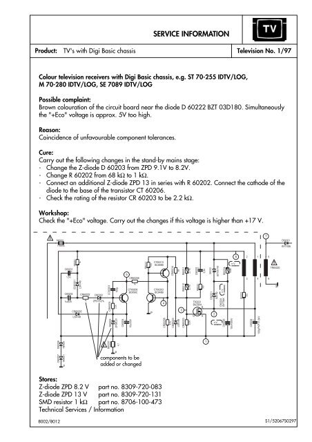
Colour television receivers with Digi Basic chassis, e.g. ST 70-255 IDTV/LOG,<br />
M 70-280 IDTV/LOG, SE 7089 IDTV/LOG<br />
C60201<br />
F<br />
1,5n<br />
R60201<br />
1k<br />
CD60202<br />
LS4148<br />
CR60203<br />
2,2k<br />
C60204<br />
+<br />
10u/50V<br />
CT60213<br />
BC858B<br />
CT60203<br />
BC848B<br />
CR60208<br />
CR60214<br />
4,7k<br />
CD60223<br />
68<br />
C60221<br />
F<br />
3,9n<br />
BA159<br />
D60224<br />
n.V.<br />
BYT54K<br />
R60224<br />
100k<br />
n.V.<br />
Television No. 1/97<br />
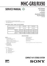
Possible complaint:<br />
Brown colouration of the circuit board near the diode D 60222 BZT 03D180. Simultaneously<br />
the "+Eco" voltage is approx. 5V too high.<br />
Reason:<br />
Coincidence of unfavourable component tolerances.<br />
Cure:<br />
Carry out the following changes in the stand-by mains stage:<br />
- Change the Z-diode D 60203 from ZPD 9.1V to 8.2V.<br />
- Change R 60202 from 68 kΩ to 1 kΩ.<br />
- Connect an additional Z-diode ZPD 13 in series with R 60202. Connect the cathode of the<br />
diode to the base of the transistor CT 60206.<br />
- Check the rating of the resistor CR 60203 to be 2.2 kΩ.<br />
Workshop:<br />
Check the "+Eco" voltage. Carry out the changes if this voltage is higher than +17 V.<br />
D60208<br />
D60207<br />
1N4001<br />
1N4001<br />
C60202<br />
+<br />
P<br />
1u/63V<br />
CR60202<br />
1k<br />
D60202<br />
ZPD13/2%<br />
D60203<br />
R60207<br />
ZPD8,2V<br />
P<br />
4,7<br />
CT60206<br />
BC858C<br />
components to be<br />
Bauteile added or die changed zusätzlich<br />
einzubauen oder zu ändern sind.<br />
Stores:<br />
Z-diode ZPD 8.2 V part no. 8309-720-083<br />
Z-diode ZPD 13 V part no. 8309-720-131<br />
SMD resistor 1 kΩ part no. 8706-100-473<br />
Technical Services / Information<br />
8002/8012<br />
TV's with Digi Basic chassis<br />
R60213<br />
100<br />
P<br />
4<br />
LS4148<br />
R60211<br />
R60212<br />
3<br />
CR60223<br />
2,7M<br />
2,7M<br />
220K<br />
R60221<br />
330<br />
T60223<br />
BUZ90A<br />
D<br />
G<br />
S<br />
1<br />
D60222<br />
D60221<br />
2<br />
BZT03D180<br />
n.V.<br />
C60226<br />
10n/1000V<br />
6<br />
R60222<br />
2<br />
C60224<br />
F<br />
1<br />
3 4<br />
330<br />
100p/FKP1/1,6kV<br />
7<br />
5<br />
6<br />
TR60220<br />
M<br />
D61001<br />
BYT53B<br />
S1/52067S0297
Product:<br />
SERVICE INFORMATION<br />
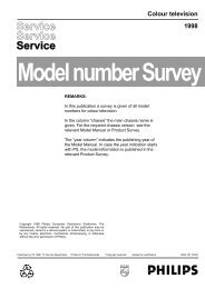
TVR 3701 SV Television No. 2/97<br />
Portable mono TV/VCR combination TVR 3701 SV<br />
Possible complaint:<br />
Mains voltage dependent chirp audible in stand-by mode.<br />
Cure:<br />
Fit an additional transistor stage as shown below into the power supply unit at IC 7310<br />
(MC 44603 P).<br />
CURRENT SENSE<br />
INPUT<br />
3359<br />
7<br />
CURRENT<br />
SENSE<br />
330<br />
IC 7310<br />
MC 44603P<br />
Buffer<br />
THERMAL<br />
SHUTDOWN Vref Vcc<br />
2320<br />
2,2 µ<br />
Dmax & SOFT-SART<br />
CONTROL<br />
OVERVOLTAGE<br />
MANAGEMENT<br />
11<br />
fit these components<br />
diese Bauteile<br />
additionally<br />
zusätzlich einbauen<br />
Workshop:<br />
Carry out when complaints are received.<br />
Stores:<br />
Diode BAT 85 part no. 8309-198-085<br />
Technical Services / Information<br />
UVLO1<br />
Vref<br />
2<br />
3<br />
4<br />
6<br />
BC 548 B<br />
8002/8012 52067S0397<br />
BAT 85<br />
1 kΩ<br />
100 pF<br />
4,7 kΩ
Product:<br />
SERVICE INFORMATION<br />
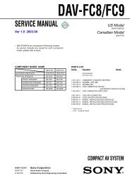
CUC 7301 Television No. 3/97<br />
37 cm colour television receivers with chassis CUC 7301 text e.g.: P 37-730 text<br />
Possible complaint:<br />
Teletext operation is not possible in “AV” programme position.<br />
Reason:<br />
The video switch-IC 2807 (TEA 2114) is not fitted in 37 cm television receivers.<br />
Cure:<br />
Retrofit the following components:<br />
IC 2807 TEA 2114<br />
C 2815 1 μF<br />
C 2810 100 μF<br />
C 2811 0.1 μF<br />
CR 2813 270 Ω<br />
CR 2814 270 Ω<br />
In addition, change the polarity of 2.2 μF electrolytic capacitor C 2816 (negative terminal to<br />
pin 8 of IC 2810) and remove bridge BR␣ 056.<br />
C2810<br />
+<br />
100u/25V<br />
FBAS<br />
SC<br />
FBAS<br />
EURO-AV<br />
4<br />
3<br />
8<br />
C2815<br />
+<br />
1u/100V<br />
7<br />
CC2811<br />
BR 056<br />
0dB<br />
IC 2807<br />
0dB<br />
6dB<br />
0,1u<br />
1<br />
TEA 2114<br />
5<br />
VQ<br />
U<br />
2<br />
6<br />
CR2814<br />
270<br />
34<br />
33<br />
32<br />
31<br />
30<br />
29<br />
28<br />
CR2813<br />
CR2807<br />
H<br />
SYNC<br />
19 36 37 18<br />
Technical Services / Information 8002/8012 52097S0497<br />
15<br />
C2816<br />
+<br />
2,2u/100V<br />
47k<br />
R<br />
G<br />
16<br />
17<br />
8 12 13 22 24 25 23 21 2 3 7 40<br />
M<br />
2,2n<br />
CC2810<br />
V<br />
SYNC<br />
B<br />
BLANK<br />
BR009<br />
RGB-REF<br />
IC 2810<br />
SAA 5254 P/E<br />
Workshop:<br />
Carry out when complaints are received.<br />
The circuit board is already prepared to be fitted with these components.<br />
Stores:<br />
IC TEA 2114 part no. 8305-362-114<br />
Electrolytic capacitor 1 μF/100 V part no. 8452-967-325<br />
Electrolytic capacitor 100 μF/25 V part no. 8452-967-135<br />
Capacitor 0.1 μF part no. 8555-267-173<br />
SMD resistor 270 Ω part no. 8706-297-059<br />
270<br />
35<br />
11<br />
OSC OUT<br />
26<br />
OSC IN<br />
6<br />
1<br />
27<br />
9<br />
10<br />
20<br />
4<br />
5<br />
14<br />
38<br />
39<br />
M
Product<br />
Service Information<br />
Colour television receivers with chassis CUC 7303 and 7305, e.g. P 37-071,<br />
T 51-720 text, T 55-731 text<br />
Possible complaint:<br />
After having replaced EEPROM IC 830 X24C02, the Automatic Tuning<br />
System does not find all stations.<br />
Reason:<br />
The EEPROM on this chassis contains information about so-called band<br />
limits in its memory cells 235 to 239. These values are programmed in the<br />
factory in a special alignment adapter and vary with the individual tuner<br />
and Z-diode D 683 (ZTK 33). When fitting a new EEPROM, any value is<br />
stored in the memory cells. Consequently, the ATS does not scan the<br />
complete frequency range.<br />
Cure:<br />
Clear the band limit values (content of the memory cells 235 to 239) as<br />
follows:<br />
1. Call up the Service Menu (depress button „i“ on the remote control<br />
while switching on with the mains switch).<br />
2. With the remote control buttons „P+/P-“ select line „AGC ALIGN“.<br />
3. During a period of 5 seconds operate the buttons „AUX“ and „OK“<br />
sequentially.<br />
The ATS search function now scans the whole frequency range.<br />
Note: When the band limits are cleared individual stations may be found<br />
twice!<br />
Workshop:<br />
Clear the band limit values when having replaced the tuner, Z-diode<br />
D 683 or EEPROM IC 830.<br />
Stores:<br />
none<br />
Note to our Service Information 1/97 (subject: Digi Basic colour television<br />
receivers - „Eco“ voltage is about 5V too high)<br />
Due to repeated inquiries we would like to point out that resistor R 60202<br />
that is to be changed from 68 kΩ to 1 kΩ is a lead-type version and not a<br />
SMD component.<br />
52127S0997, 8002/8012<br />
TV<br />
Serial No 5/97<br />
Central<br />
After-Sales Service<br />
1/1
Product<br />
Service Information<br />
Colour television receivers with chassis CUC 7350, e.g. ST 55-750 text<br />
Possible complaint:<br />
Despite the modifications carried out according to our TV Service<br />
Information 9/96 the television sets switch occasionally to Standby<br />
after a prolonged time of operation.<br />
Reason:<br />
Temperature drift of the +E operating voltage by about 0.2 to 0.3V<br />
caused by Z-diode CD 61023. Consequently, IC 34015 TDA 8374<br />
switches off with sudden black/white changes in the picture content or<br />
changing scenes.<br />
This Z-diode has been introduced later and therefore is drawn in only<br />
in the 1st Supplement to the CUC 7350 Service Manual.<br />
Cure:<br />
The position of the Z-diode is X=10, Y=150. Unsolder this diode and<br />
insert a SMD resistor 1206 1.2Ω 1% in this place.<br />
Stores<br />
SMD resistor 1206 1.2Ω 1% part no. 8706-297-475<br />
150<br />
10<br />
S2R1521370000, 8002/8012<br />
Lötseite<br />
Copper Side<br />
TV<br />
Serial No 6/97<br />
Central<br />
After-Sales Service<br />
1/1
Product<br />
Service Information<br />
Colour television receivers with chassis CUC 7300, e.g. P 37-740 SAT, and all<br />
sets retrofitted with the built-in satellite receiver SER 7300<br />
Possible complaint:<br />
The sound disappears suddenly during the reception of a satellite<br />
programme and is audible again only when changing the programme or<br />
switching the TV off and on again.<br />
Reason:<br />
IC MSP 3400 on the SAT Module hangs up by static charges entering the<br />
Reset input of the IC.<br />
Cure:<br />
Unsolder the SMD capacitor CC 3800 from its place on the SAT Module<br />
and resolder it at the place indicated on the figure below.<br />
CBR74<br />
CR3960<br />
Stores:<br />
none<br />
S3/521570000, 8002/8012<br />
CC 3800 an dieser<br />
Position auflöten<br />
Resolder CC 3800 at<br />
this place<br />
CC3975<br />
CC3961<br />
CR3950<br />
CR3949<br />
CR3800<br />
CR3942<br />
CC3947<br />
CR3947<br />
CC3948<br />
CBR62<br />
CC3974<br />
CC3945<br />
CR3945<br />
CC3976<br />
CR3941<br />
CR3943<br />
CR3946<br />
CT3947<br />
CC3967<br />
CBR63<br />
CC3966<br />
CBR31<br />
CBR69<br />
CR3807<br />
CT3945<br />
CC396<br />
CBR66<br />
CBR54<br />
CBR64<br />
CBR30<br />
CBR67<br />
CC3804<br />
CBR58<br />
CBR2<br />
CBR56<br />
CBR53<br />
CBR57<br />
CBR61<br />
CC3802<br />
CR3802<br />
CR3801<br />
CBR52<br />
CC3806<br />
CBR55<br />
28<br />
1<br />
CC3801<br />
CBR44<br />
CBR43<br />
CBR42<br />
CR3907<br />
CBR59<br />
R3903<br />
CR3804<br />
CR3908<br />
CIC3800<br />
CBR40<br />
CBR39<br />
CBR38<br />
CBR46<br />
CC3958<br />
CC 3800 an dieser<br />
Position Unsolder CC ausbauen 3800<br />
CR3906<br />
CBR45<br />
15<br />
14<br />
CBR48<br />
CBR34<br />
TV<br />
Serial No.7/97<br />
Central<br />
After-Sales Service<br />
1/1<br />
CC3803<br />
CC3800<br />
CC3903<br />
CBR51<br />
CR3891<br />
CBR50<br />
CBR37<br />
CBR3<br />
CR3915<br />
CR3962<br />
CBR41<br />
CBR47<br />
CBR33<br />
CBR49<br />
CR3961<br />
CBR3
Product<br />
Service Information<br />
Colour television receivers with chassis Digi Basic CUC 1825, 1826 and<br />
1827, e.g. ST 63-255 IDTV/LOG, M 70-281 IDTV/LOG, SE 7089 IDTV/LOG<br />
Possible complaint:<br />
The TV receiver can be switched on only with the remote control handset.<br />
When switching on with the mains switch, the receiver always goes to<br />
Standby mode.<br />
Reason:<br />
Unwanted activation of the protection circuit at the moment the TV<br />
receiver is switched on.<br />
Cure:<br />
Change the electrolytic capacitor C 58004 (on pin 6 of IC 58010) from<br />
10 μF to 22 μF/25V.<br />
Workshop:<br />
Carry out when complaints are received.<br />
Important note: Since the Digi Basic TV receivers work without a wiper<br />
contact in the mains switch the EEPROM stores the operating mode<br />
(Standby or „On“) at the time the set is switched off with the mains<br />
switch. That is why the set will only start with „On“ the next time it is<br />
switched on (power on) if it was switched off from this mode.<br />
Stores:<br />
Electrolytic capacitor 22 μF/25V part no. 8452-967-126<br />
S4/521970000, 8002/8012<br />
TV<br />
Serial No 8/97<br />
Central<br />
After-Sales Service<br />
1/1
Product<br />
Service Information<br />
Colour television receivers with Digi 6 chassis - CUC 1952, 1983, 1984 with<br />
built-in SER 150/SER 150 ET Satellite Receiver - e.g. Denver SE 8216/9<br />
Ref./PIP, M 82-269/9 Reference<br />
Possible complaint:<br />
On reception of the channel Premiere via satellite the connected decoder<br />
does not operate while this station is decoded perfectly when received via<br />
a cable installation.<br />
Reason:<br />
The video crossbar IC TDA 6417 is overloaded on satellite reception.<br />
Cure:<br />
Change the SMD resistor CR 43209 from 1 MΩ to 470 kΩ. It is also<br />
possible to connect another 1 MΩ resistor in parallel when carrying out<br />
repairs.<br />
Workshop:<br />
The position of the SMD resistor is X=102, Y=187.<br />
Stores:<br />
SMD resistor 470 kΩ 0805 part no. 8706-100-337<br />
SMD resistor 1 MΩ 0805 part no. 8706-100-145<br />
52197S1297, 8002/8012<br />
TV<br />
Serial No 9/97<br />
Central<br />
After-Sales Service<br />
1/1
Service Information<br />
Product Mono TV Recorders TVR 3710, 5100 and 5500<br />
Possible complaint:<br />
TV Recorder does not operate.<br />
Reason:<br />
Defect in transistor 7352 (MTP 3055E) caused by static discharges in the<br />
TV Recorder.<br />
Cure:<br />
Fit an additional Z-diode BZX 83B15 between gate and source to suppress<br />
voltage peaks at the gate.<br />
Workshop:<br />
The Z-diode must strictly be retrofitted if the transistor 7352 fails. This<br />
change is carried out already in the factory.<br />
Stores:<br />
Z-diode BZX 83B15 part no. 8309-720-115<br />
522370000, 8002/8012<br />
MTP<br />
3055E<br />
G D S<br />
LM317T<br />
5D1<br />
BZX 83B15<br />
fit zusätzlich additionally<br />
einbauen<br />
7352<br />
MTP 3055E<br />
3353<br />
7351<br />
BC 548B<br />
1 k<br />
3354<br />
220 k<br />
14H<br />
TV<br />
Serial No 10/97<br />
Central<br />
After-Sales Service<br />
1/1
Service Information<br />
Product Colour television receivers with Digi IV chassis - CUC 1821/1851/1881/1892<br />
and 1981, e.g. M 70-781 IDTV, M 70-791 IDTV, M 82-102 IDTV, M 95-102 IDTV,<br />
M 82-169 PALplus<br />
Possible complaint:<br />
Mains supply switching transistor fails occasionally.<br />
Reason:<br />
Breaks may be found after a long time of use at the solder pads in the area<br />
of the mains supply stage especially at the connections of the mains supply<br />
transformer.<br />
Cure:<br />
Re-solder the connections in this area.<br />
Workshop:<br />
For reasons of operational reliability and irrespective of the fault, re-solder<br />
the 1.5Ω resistor R 622 and the choke L 663 (both components are in the<br />
area of the mains supply) with great care using ample tin.<br />
Stores:<br />
None<br />
522870000, 8002/8012<br />
TV<br />
Serial No 11/97<br />
Central<br />
After-Sales Service<br />
1/1
Product<br />
Product<br />
Service Information<br />
Colour television receivers with 82/70 cm Toshiba picture tube and Digi 6<br />
chassis - e.g. M 82-269/9 Ref, SE 8216/9 Ref/PIP, M 70-269/9 Ref, SE 7016/9<br />
Ref/PIP Trento<br />
Possible complaint:<br />
Audible hum or buzzing noise from the bass loudspeaker.<br />
Reason:<br />
Magnetic radiation from the deflection yoke into the loudspeaker.<br />
Cure:<br />
To reduce the radiation from the yoke exchange the bass box loudspeaker<br />
for a type with compensating coil.<br />
Workshop:<br />
Carry out when complaints are received.<br />
Stores:<br />
Loudspeaker with compensating coil, part no. 19154-031.61<br />
Colour television receivers with Digi Basic chassis CUC 1805/1825/1826<br />
and 1827, eg. ST 63-255 IDTV/LOG, ST 72-261 IDTV/LOG, Boston SE 7090<br />
IDTV/LOG<br />
Possible complaint:<br />
TV set does not start occasionally.<br />
Reason:<br />
„Cold“ solder connection of the wire bridge „BR 129“ with the earthing pad<br />
on the component side in the area of the mains supply stage. Consequently,<br />
the standby power supply does not start up reliably.<br />
Workshop:<br />
Re-solder the chassis connection in every television receiver coming in for<br />
repair using ample solder tin.<br />
Stores:<br />
None<br />
S6/522870000, 8002/8012<br />
TV<br />
Serial No. 12/97<br />
Central<br />
After-Sales Service<br />
1/1
Product<br />
Product<br />
Service Information<br />
Colour television receivers with chassis CUC 7301/7301F, e.g. P 37-070,<br />
T 51-730 text, T 55-730/5 text<br />
Possible complaint:<br />
No picture. High tension is available.<br />
Reason:<br />
The transistors CT 181, CT 186, CT 191 and CT 193 failed because of high<br />
voltage sparks inside the picture tube.<br />
Cure:<br />
Replace the defective transistors and solder an additional diode 1N4148<br />
from pin 7 of the „RGB“ lead (to picture tube panel) to the ground pin 4 on<br />
the chassis. Connect the anode of the diode with pin 4.<br />
Workshop:<br />
Fit the additional diode when the transistors failed.<br />
Stores:<br />
Diode 1N4148 part no. 8309-215-045<br />
Correction of Service Information 9/97<br />
Colour television receivers with Digi 6 chassis 1952, 1983, 1984 and built-in<br />
satellite receiver SER 150/SER 150 ET - e.g. Denver SE 8216/9 Ref./PIP,<br />
M 82-269/9 Reference<br />
Possible complaint:<br />
On reception of the channel Premiere via satellite the connected decoder<br />
does not operate while this station is decoded perfectly when received via a<br />
cable installation.<br />
Reason:<br />
The video crossbar IC TDA 6417 is overloaded on satellite reception.<br />
Cure:<br />
The change of the resistor CR 43209 from 1 MΩ to 470 kΩ as described in<br />
our Service Information 9/97does not produce the desired effect in every<br />
case. Therefore change the resistor CR 43209 from 1 MΩ to 330 kΩ when<br />
carrying out repairs. It is also possible to connect a 560 kΩ resistor in<br />
parallel with the 1 MΩ.<br />
Workshop:<br />
The position of the SMD resistor is X = 102, Y = 187.<br />
Stores:<br />
SMD resistor 330 kΩ 0805 part no. 8706-100-333<br />
SMD resistor 560 kΩ 0805 part no. 8706-100-139<br />
R2S7/523070000, 8002/8012<br />
TV<br />
Serial No 13/97<br />
Central<br />
After-Sales Service<br />
1/1
Product<br />
Product<br />
Service Information<br />
Colour television receivers with chassis CUC 7303, e.g. P 37-731 text,<br />
P 45-731 text, T 55-731 text<br />
Possible complaint:<br />
Pronounced NF crackling when switching off with the mains switch.<br />
Cure:<br />
Change the Z-diode D 323 from ZPD 8.2V to 9.1V 2%. Additionally, solder a<br />
diode 1N 4148 in parallel with the resistor CR 323. Connect the cathode of<br />
this diode with the +B voltage.<br />
Workshop:<br />
Carry out on request. This change has already been introduced in<br />
production.<br />
Stores:<br />
Z-diode ZPD 9.1V 2% part no. 8309-720-092<br />
Diode 1N4148 part no. 8309-215-045<br />
Colour television receivers with chassis CUC 7303/7305/7350 and the<br />
picture tube panels 29305-022.16/-022.17, e.g. P 37-731 text, P 45-731 text,<br />
T 55-731 text, P 37-731/12 text, ST 55-750 text, XS 55/1, Lissabon SE 5576<br />
text<br />
Possible complaint:<br />
Failure of the RGB output stages (picture tube panels 29305-022.16 and<br />
-022.17) or of the teletext function.<br />
Reason:<br />
The semiconductors are destroyed by high-voltage sparks within the picture<br />
tube.<br />
Cure:<br />
On the picture tube panels -022.16/-022.17, insert an additional 1.5 kΩ<br />
composite carbon resistor (do not use a carbon film resistor!) into the circuit<br />
path to the screen grid connection of the picture tube socket. Ensure that<br />
the break is 2mm wide at least (see figure) to avoid sparking.<br />
Workshop:<br />
Refit the resistor in any case if the above<br />
mentioned semiconductors failed.<br />
Stores:<br />
Only altered picture tube panels<br />
29305-022.16/-022.17<br />
Composite carbon resistor 1.5 kΩ,<br />
part no. 8702-401-077.<br />
R3S8/523970000, 8002/8012<br />
7<br />
additional resistor<br />
zusätzlicher Widerstand<br />
break<br />
Trennstelle<br />
TV<br />
Serial No 14/97<br />
Central<br />
After-Sales Service<br />
1/1
Service Information<br />
Product Colour television receivers with Digi 6 chassis CUC 1842, 1894, 1952, 1962<br />
and 1983, e.g. M 72-410 Ref., Denver SE 8216/9 PAL Plus, M 70-269/9 Ref.<br />
Possible complaint:<br />
Vertical output stage TDA 4173 fails or thin white lines similar to retrace<br />
stripes are visible.<br />
Reason:<br />
Inherent instability of the vertical output stage IC TDA 4173 AF.<br />
Cure:<br />
- Should above mentioned symptoms appear do not fail to exchange<br />
TDA 4173 AF and solder additionally a 1 nF foil capacitor from pin 1 and<br />
from pin 7 each to pin 4 (-K voltage) on the copper side.<br />
- Check the mounting position of the vertical output-IC. If the position of<br />
the IC is too low, the pins may temporarily come into contact with<br />
the chassis connection on the upper side causing the IC to fail.<br />
Additionally, the circuit may already be damaged by the building up<br />
force of pressure resulting in a long-term failure. Therefore replace<br />
TDA 4173 AF also if it has not been fitted correctly!<br />
Workshop:<br />
When fitting the new IC TDA 4173 AF take care of the correct position of the<br />
holding clamp and solder in the additional capacitors!<br />
This change has been generally introduced.<br />
Stores:<br />
Foil capacitor 1 nF part no. 8555-367-525<br />
IC TDA 4173 AF part no. 8305-344-173<br />
≈5<br />
52397S1897, 8002/8012<br />
correct position position is too low<br />
richtige Montage<br />
zu tiefe Montage<br />
TV<br />
Serial No 15/97<br />
Central<br />
After-Sales Service<br />
1/1
Service Information<br />
Product Colour television receivers with Digi Basic and Digi 6 chassis - CUC 1805,<br />
1825, 1826, 1827, 1828, 1842, 1894, 1952, 1962 and 1983<br />
e.g. M 72-410 Ref., Denver SE 8216/9 PAL Plus, M 70-269/9 Ref.<br />
Possible complaint:<br />
Interference lines in the picture or complete failure of the tuner.<br />
Reason:<br />
Failure of the PLL-IC TY 44860 within the tuner.<br />
Cure:<br />
After having replaced the tuner, solder an additional Z-diode ZPD 33 B<br />
(2% tolerance) on the copper side of the chassis board from pin 1 to the<br />
multipoint connector of the signal module to chassis (anode to chassis).<br />
Workshop:<br />
Retrofit the Z-diode if the tuner failed.<br />
Stores:<br />
Z-diode ZPD 33 B (2%) part no. 8309-707-135<br />
G1/524170000, 8002/8012<br />
TV<br />
Serial No 16/97<br />
Central<br />
After-Sales Service<br />
1/1
Service Information<br />
Product Colour television receivers with Digi Basic chassis - CUC 1806, 1825, 1826,<br />
1827, 1829, 1830 with the picture tube panels 29305-122.04/-122.10/-122.12<br />
and -122.17<br />
e.g. ST 70-255 IDTV/LOG, ST 72-261 IDTV/LOG, Atlanta SE 7220 IDTV/LOG,<br />
ST 72-261 IDTV/LOG<br />
Possible complaint:<br />
Failure of the RGB output IC‘s TDA 6111.<br />
Reason:<br />
The RGB output IC‘s are destroyed by high voltage sparks.<br />
Cure:<br />
Directly from the outputs (pin 8) of the three output IC‘s TDA 6111 connect<br />
one additional diode BAV 21 each to chassis and one diode each to the<br />
+200 voltage (see figure).<br />
Workshop:<br />
The insertion of the three diodes which are to be connected to +200 is<br />
already prepared on the picture tube panel by the diodes D 734, D 754 and<br />
D 774.<br />
The three diodes which are to be connected to chassis are to be soldered on<br />
to the copper side from pin 8 to pin 4 (anode to pin 4).<br />
Stores:<br />
Diode BAV 21 part no. 8309-200-021<br />
IC TDA 6111 part no. 8305-336-111<br />
Only modified picture tube panels 29305-122.04/-122.10/-122.12 and<br />
-122.17.<br />
+12V +200<br />
G2S9/524170000, 8002/8012<br />
3<br />
9<br />
1<br />
2 6<br />
TDA<br />
6111<br />
4<br />
zusätzliche additional<br />
Dioden diode BAV 21 21<br />
8<br />
7<br />
to picture zur<br />
Bildröhre<br />
tube<br />
TV<br />
Serial No 17/97<br />
Central<br />
After-Sales Service<br />
1/1
Service Information<br />
Product Colour television receivers ST 72-261 IDTV/LOG and ST 72-261/8 IDTV/LOG<br />
with Toshiba picture tube<br />
Possible complaint:<br />
Picture seems to be unsharp or the TV switches occasionally to Standby.<br />
Reason:<br />
Short circuit in the serially connected capacitors C 64001 and C 64002<br />
(150pF/6kV each) on the dynamic focusing board.<br />
Cure:<br />
1. Replace the capacitors C 64001 and C 64002 on the dynamic focusing<br />
board.<br />
2. Check the Ug2/focus control unit on the picture tube socket board<br />
29305-122.12.<br />
If the TV is fitted with version 29201-361.01 or -361.11, this focus control<br />
unit must be replaced by version 29201-361.04. Version 29201-361.20<br />
needs not to be replaced but can remain in the TV set.<br />
3. Attention: When fitting the new Ug2/focus control unit, please note the<br />
following wiring instructions:<br />
- Insert the blue lead - provided with a white mark - of the Ug2/focus<br />
control unit into the focus voltage connection of the diode split<br />
transformer.<br />
- Solder the shorter blue lead of the Ug2/focus control on to the focus<br />
voltage connection of the focusing board.<br />
- Route this lead from the focusing board to the focus voltageconnection<br />
of the picture tube socket.<br />
- Re-attach the cover of the focusing board.<br />
4. Replace the diode split transformer 29201-680.01. Due to the failure of<br />
the capacitor C 64001 or C 64002 the resistance of the focus resistor<br />
in the diode split transformer changes so that an optimum adjustment of<br />
the picture sharpness is no longer possible.<br />
Workshop:<br />
Please check the wiring of the focus leads according to point 3 of every<br />
TV receiver of type ST 72-261 IDTV/LOG and ST 72-261/8 IDTV/LOG coming<br />
in for repair!<br />
Focus adjustment:<br />
- Feed in a convergence test pattern.<br />
Set contrast to maximum. Set the brightness so that the black<br />
background of the test pattern just becomes visible.<br />
- With the focus control on the picture tube socket board, adjust the<br />
horizontal lines for maximum sharpness.<br />
- Afterwards, adjust the vertical lines with the focus control on the<br />
focusing board for maximum sharpness.<br />
- Repeat this adjustment to achieve the best result possible.<br />
Stores:<br />
Capacitor 150pF/6kV part no. 8502-200-066<br />
Ug2/focus control unit part no. 29201-361.04<br />
Diode split transformer part no. 29201-680.01<br />
Dynamic focusing board part no. 29305-025.26<br />
52467S2097, 8002/8012<br />
TV<br />
Serial No 18/97<br />
Central<br />
After-Sales Service<br />
1/1
Service Information<br />
Product Satellite Receivers STR 631/632/641 and 642<br />
Possible complaint:<br />
No sound after the receiver has been operated in standby mode for a<br />
prolonged period of time. The sound is audible again only on disconnecting<br />
the mains plug and switching the satellite receiver on again.<br />
Reason:<br />
As advised by our Service Information 4/97, this phenomenon is caused by<br />
IC STV 400 STV 0056A but cannot be limited to certain IC lots.<br />
Cure:<br />
Solder one SMD Z-diode 8.2V each in parallel with the electrolytic<br />
capacitors C 427 (pin 49 IC400) and C 436 (pin 38 IC400) which are<br />
connected to chassis.<br />
Workshop:<br />
The additional Z-diodes can be soldered on to the copper side directly<br />
between the connections of the electrolytic capacitors (anode to negative<br />
connection of the electrolytic capacitor).<br />
Retrofit the diodes in every satellite receiver coming in for repair.<br />
Stores:<br />
SMD Z-diode 8.2 C part no. 8309-455-082<br />
52497S2197, 8002/8012<br />
TV<br />
Serial No. 19/97<br />
Central<br />
After-Sales Service<br />
1/1
Service Information<br />
Product Colour television receivers MW 70-100/8, M 72-100 and M 72-100/8<br />
Possible complaint:<br />
Audible buzzing noise that does not come out from the loudspeaker.<br />
Reason:<br />
The mains suppressor chokes on the mains switch module may be in<br />
contact with the protective screen producing vibrations thereby.<br />
Cure:<br />
Unsolder the protective screen and the mains suppressor choke and fit a<br />
suppressor choke with part number 29500-834.97. Since this choke is<br />
provided with an additional compensating coil the protective screen is no<br />
more needed.<br />
Workshop:<br />
Carry out on request.<br />
Stores:<br />
Mains suppressor choke part no. 29500-834.97<br />
52497S2297, 8002/8012<br />
TV<br />
Serial No. 20/97<br />
Central<br />
After-Sales Service<br />
1/1
Product<br />
Product<br />
Service Information<br />
Colour television receivers with Digi Basic chassis - CUC 1825 and 1826, e.g.<br />
ST 63-255 IDTV/LOG, Boston ST 270 IDTV/LOG, ST 72-261 IDTV/LOG<br />
Possible complaint:<br />
Audible short noise building up when switching off with the mains switch.<br />
Cure:<br />
Solder an additional diode 1N4148 (cathode to pin 5) between pin 81 and<br />
pin 5 of the processor CIC 80050.<br />
Workshop:<br />
Carry out on request.<br />
Stores:<br />
Diode 1N4148 part no. 8309-215-045<br />
Colour television receivers with chassis CUC 2030 - ST 63-700 text and<br />
ST 70-700 text<br />
Possible complaint:<br />
Vertical jittering of the videotext and menus displayed on the screen.<br />
Reason:<br />
The vertical sync pulse at the input of processor CIC 81050 pin 46 is<br />
compressed.<br />
Cure:<br />
Switch an additional 120 kΩ resistor from the base of CT 46009 to chassis.<br />
Workshop:<br />
Carry out on request. This modification has generally been introduced.<br />
Stores:<br />
None<br />
52018S2297, 8002/8012<br />
TV<br />
Serial No. 1/98<br />
Central<br />
After-Sales Service<br />
1/1
Product<br />
Product<br />
Product<br />
Service Information<br />
Risks of failure of electric connections (solder pads) caused by ageing<br />
For reasons of thermal load and mechanical stress solder pads at positions<br />
where high voltages and /or currents are effective involve special technical<br />
problems.<br />
In this connection we would like to refer you to our Service Information<br />
bulletin „General 1/95“ which dealt in great detail with this subject.<br />
Solder pads which should be checked with special care in every set coming<br />
in for repair are for example:<br />
- within the line output stage, the connections of line and diode split<br />
transformers, connecting pins of the yoke plug, components of the +A<br />
supply rail as well as the capacitors and coils within the deflection circuit.<br />
- within the mains supply stage, the transformer connections, the<br />
connections of the rectifier and charging capacitor as well as the<br />
connections of the stabilizing ICs.<br />
Satellite Receivers - memory EEPROMs<br />
The part numbers of the memory ICs specified in the Service Manual are not<br />
correct.<br />
The preprogrammed EEPROMs are available under the following part<br />
numbers:<br />
Stores:<br />
STR 641 IC 601 part no. 72008-668.6900<br />
STR 642 IC 601 part no. 72008-688.7000<br />
STR 642 IC 602 part no. 72008-688.7100<br />
STR 100 DX CIC 1420 part no. 72008-668.7200<br />
STR 110 CIC 1420 part no. 72008-668.7300<br />
Correction of Service Information bulletin 12/97<br />
Colour television receivers with 82/70cm Toshiba picture tubes and Digi 6<br />
chassis, e.g. M82-269/9 Ref, SE 8216/9 Ref/PIP, M 70-269/9 Ref, SE 7016/9<br />
Ref/PIP Trento - Hum and buzzing noise<br />
The part number of the loudspeaker with compensating coil specified in the<br />
Service Information is not correct. The correct number should read 19154-<br />
043.6100. Please correct your documents.<br />
52038000, 8002/8012<br />
TV<br />
Serial No. 2/98<br />
Central<br />
After-Sales Service<br />
1/1
Service Information<br />
Product Colour television receivers P 37-731 text and P 45-731 text with CUC 7303 text<br />
Possible complaint:<br />
Teletext information cannot be received via the Euro-AV connection, for<br />
example when connecting a Grundig Micro-Sat Receiver.<br />
Cure:<br />
For activating the teletext mode in „AV“ progamme position retrofit the<br />
following components:<br />
- IC 2807 TEA 2114<br />
- C 2815 1μF/100V<br />
- C 2810 100μF/25V<br />
- CC 2811 0.1μF<br />
- CR 2814 390Ω 5% (structural shape 0805)<br />
- CR 2813 change from 0Ω to 270Ω 5% (structural shape 1206)<br />
- Solder a wire bridge BR 077 (+B‘ voltage to IC 2807 pin 7)<br />
- Unsolder the electrolytic capacitor C 2816 and re-solder it to position<br />
C 2817 (positive connection to pin 30 of processor IC 850).<br />
- Remove the bridge BR 056.<br />
Workshop:<br />
The circuit board is already prepared for fitting the components.<br />
The steps for retrofitting television receivers with chassis CUC 7301 are<br />
described in our Service Information TV 3/97.<br />
Stores:<br />
IC TEA 2114 part no. 8305-362-11400<br />
Electrolytic capacitor 1μF/100V part no. 8452-967-32500<br />
Electrolytic capacitor 100μF/25V part no. 8452-967-13500<br />
SMD capacitor 0.1μF part no. 8672-167-18700<br />
52028000, 8002/8012<br />
TV<br />
Serial No. 3/98<br />
Central<br />
After-Sales Service<br />
1/1
Service Information<br />
Product Colour television receivers with chassis Digi Basic (CUC 1805/1825), Basic+<br />
(1826/1827) and Basic++ (1806/1828/1829/1830)<br />
e.g. M 70-280 IDTV/LOG, ST 72-261/8 IDTV/LOG, M 72-100, Atlanta SE 7220<br />
IDTV/LOG, ST 70-270 IDTV<br />
Possible complaint:<br />
When switching on with the mains switch the television receiver goes to<br />
Standby and cannot be switched on again with the remote control handset.<br />
Reason:<br />
Failure of transistor CT 80085 BC 858B (position X=148, Y=18).<br />
Cure:<br />
On replacement of the transistor, solder an additional diode 1N4148 from<br />
the base to the emitter (anode to base) of CT 80085 and change the resistor<br />
CR 80083 from 0 Ω to 47 Ω 5% (structural shape 0805).<br />
Workshop:<br />
The additional diode can be fitted to the solder side between the base of<br />
CT 80085 and the cathode of diode CD 80081.<br />
Stores:<br />
Transistor BC 858B part no. 8301-003-85800<br />
Diode 1N4148 part no. 8309-215-04500<br />
+N<br />
zusätzliche additional<br />
Diode diode<br />
1N4148<br />
+H<br />
G1/52068000, 8002/8012<br />
CR change 80083<br />
von CR 80083 0 Ω in<br />
47<br />
from<br />
Ω ändern<br />
0 Ω<br />
to 47 Ω<br />
CT 80085<br />
BC 858 B<br />
2<br />
IC<br />
IC<br />
80040<br />
MC<br />
80040<br />
33164<br />
1<br />
MC 33164<br />
3<br />
TV<br />
Serial No. 4/98<br />
Central<br />
After-Sales Service<br />
1/1
Service Information<br />
Product Colour television receivers with chassis CUC 2030, 2031, and 2040<br />
e.g. ST 63-700 text, ST 63-710, Melbourne SE 7210 TOP, ST 70-700 NIC/text<br />
Possible complaint:<br />
No programmes receivable.<br />
Reason:<br />
Failure of diode D 31001 ZTK 33B caused by too high a Zener current.<br />
Cure:<br />
On replacement of the the Z-diode ZTK 33B, change additionally the SMD<br />
resistor CR 31009 from 330 Ω to 680 Ω 5% (structural shape 0805) and<br />
solder an additional 0.1μF foil capacitor in parallel with Z-diode ZTK 33B.<br />
Workshop:<br />
When the Z-diode failed, change the resistor (position X=78, Y=10) and<br />
solder an additional capacitor.<br />
Stores:<br />
Z-diode ZTK 33B part no. 8305-306-00100<br />
52078S0198, 8002/8012<br />
0.1μ 0,1 µ<br />
CT CT 31005<br />
BC BC858B 858 B<br />
D 31001<br />
ZTK ZTK33B 33 B<br />
+45V<br />
change<br />
CR<br />
CR<br />
31009<br />
31009<br />
von<br />
from<br />
330<br />
330<br />
Ohm<br />
Ω<br />
in<br />
to<br />
680<br />
680<br />
Ohm<br />
Ω<br />
ändern<br />
zusätzlich fit<br />
einbauen additionally<br />
+33V +33V<br />
D 31007<br />
ZPD4,7V ZPD 4.7V<br />
TV<br />
Serial No. 5/98<br />
Central<br />
After-Sales Service<br />
1/1
Service Information<br />
Product Colour television receivers with chassis CUC 6360 and 6365<br />
e.g. SE 6376, ST 63-761 TOP, ST 70-755 TOP, XS 70/1, ST 72-761 TOP<br />
Possible complaint:<br />
Tearing of the displayed menus and teletext pages.<br />
Reason:<br />
Failure of the capacitors C 683 and C 684 of 0.1 μF each.<br />
Cure:<br />
Change the electrolytic capacitors C 681 and 682 of 220 μF/16 V each in<br />
addition to the capacitors C 683/684.<br />
Stores:<br />
None.<br />
L 678<br />
C 679<br />
5208800000, 8002/8012<br />
1<br />
C 680<br />
2,2n<br />
IC 680<br />
TDA 8137<br />
4 3<br />
6<br />
7<br />
T680<br />
BC548B<br />
C 684<br />
C 683<br />
0,1 µ<br />
C 682<br />
0,1 µ<br />
C 681<br />
220µ/16V<br />
220µ/16V<br />
TV<br />
Serial No. 6/98<br />
Central<br />
After-Sales Service<br />
1/1<br />
+H (+5 V)<br />
+5V/D
Product<br />
Product<br />
Service Information<br />
Colour television receivers with chassis Digi Basic/Basic+/Basic++<br />
CUC 1805, 1806, 1825, 1826, 1827, 1828, 1829 and 1830<br />
e.g. ST 63-255 IDTV/LOG, ST 72-261 IDTV/LOG, Boston SE 7090 IDTV/LOG,<br />
Atlanta SE 7220 IDTV/LOG<br />
Possible complaint:<br />
Jittering of the displayed menus or teletext pages when the television<br />
receiver has warmed up.<br />
Reason:<br />
Lack of stability of the oscillator circuit at processor-IC IC 80050.<br />
Cure:<br />
Change the SMD capacitors CC 46021/46022 to a 56 pF version each<br />
(structural shape 0805).<br />
Workshop:<br />
Carry out this change when complaints are received.<br />
Position CC 46021 X=93, Y=81<br />
Position CC 46022 X=96, Y=81<br />
Stores:<br />
None.<br />
Colour television receivers with chassis CUC 2030 and 2031<br />
e.g. ST 63-700 text, ST 70-780 text, Melbourne ST 7210 TOP,<br />
ST 70-700 NIC/FT<br />
Possible complaint:<br />
Jittering of the displayed menus and teletext pages.<br />
Reason:<br />
Limited vertical sync pulse on pin 46 of the processor-IC IC 81050.<br />
Cure:<br />
Connect an additional 120 kΩ resistor from the base of CT 46009 (BC 848,<br />
position X=146, Y=63) to chassis.<br />
Workshop:<br />
Carry out this change when complaints are received.<br />
Stores:<br />
None.<br />
G2/5211800000, 8002/8012<br />
TV<br />
Serial No. 7/98<br />
Central<br />
After-Sales Service<br />
1/1
Service Information<br />
Product Colour television receivers with chassis CUC 63xx, 64xx, 20xx and Digi Basic/<br />
Digi 6 - new plug-in systems<br />
The television receivers with above mentioned chassis are partly<br />
fitted with new plug-in systems between the modules and the chassis.<br />
As a consequence of this conversion, the modules with the new systems<br />
can no longer be pulled out of the chassis as usual. When trying to do<br />
so damages may be caused to the module or the chassis.<br />
The following figures show the different systems and how they can be<br />
dismounted.<br />
1. The traditional black socket terminal<br />
strips of the modules are additionally<br />
provided with locking lugs which, in<br />
addition to a module holder, prevent<br />
the module from slipping out. The<br />
module can be dismounted from above<br />
or below by pressing the locking lugs<br />
together.<br />
Fig. 1<br />
2. The modules of the colour television receivers with chassis CUC 20xx<br />
are fitted with a new plug-in system. They can be dismounted by<br />
disengaging the locking lug with a screw driver. In future, it will also be<br />
possible to release the lugs from below through additional drilled<br />
holes in the chassis.<br />
Fig. 2<br />
3. Concerning the Feature Boxes on the Digi Basic and Digi 6 chassis:<br />
Please note that in contrast to our earlier Digi chassis (Digi 3, 4 and 5)<br />
the two earth lugs of the Box for interference protection are<br />
soldered in. In the case of any defect, these lugs must be<br />
unsoldered!<br />
5213800000, 8002/8012<br />
TV<br />
Serial No. 8/98<br />
Central<br />
After-Sales Service<br />
1/1
Service Information<br />
Product Colour television receivers with chassis CUC 2030 and 2031<br />
e.g. ST 63-700 text, ST 70-780 text, Melbourne SE 7210 TOP, ST 70-700 NIC/FT<br />
Possible complaint:<br />
Programme position number (e.g. „P 14“) is continuously displayed on the<br />
screen.<br />
Reason:<br />
When having pressed the „i“ button on the remote control handset no<br />
further command is entered during a period of about 6 seconds. As a result,<br />
the TV set switches over to the continuous display mode so that the<br />
programme position number is continuously visible on the screen. As this<br />
function is not mentioned in the product descriptions, it may happen in a<br />
few cases that consumers think it to be a fault.<br />
Cure:<br />
Cancelling the continuous display mode:<br />
Call up the „Dialog Center“ menu with button „i“ and press this button a<br />
second time during a period of 6 seconds.<br />
Stores:<br />
None<br />
5214800000, 8002/8012<br />
TV<br />
Serial No. 9/98<br />
Central<br />
After-Sales Service<br />
1/1
Service Information<br />
Product Colour television receivers with chassis Digi Basic, Basic+ and Basic++<br />
CUC 1805, 1825, 1826, 1827, 1828<br />
e.g. ST 63-255 IDTV/LOG, M 70-280 IDTV/LOG, Atlanta SE 7220 IDTV/LOG,<br />
Sydney 100 SE 7020 IDTV/LOG<br />
Possible complaint:<br />
Interference in FM reception in the immediate vicinity (approx. 2m) of a<br />
switched on television receiver.<br />
Cure:<br />
The interference level can be reduced noticeably by soldering in an<br />
additional ground-to-ground connection.<br />
Workshop:<br />
Solder an insulated wire of approx. 35mm (2.5mm 2 ) in length on to the<br />
solder side of the mains supply section (between pos. R60007 and C60001)<br />
as shown below. This additional wire is used to short-circuit the ground loop<br />
which has been found to be the source of interference.<br />
Carry out this change with extreme care (primary side - VDE safety<br />
regulations!) and fix the wire additionally with a heat-set adhesive!<br />
Stores:<br />
None<br />
Solder Brücke in zwischen a bridge between diesen<br />
these Punkten points einlöten and fix it und with amit<br />
heat-set Heißkleber adhesive<br />
fixieren<br />
G3/52158S0398, 8002/8012<br />
0 1 2 3 4 5 6 7 8 9<br />
TV<br />
Serial No. 10/98<br />
Central<br />
After-Sales Service<br />
1/1
Service Information<br />
Product Colour television receivers with chassis CUC 2030<br />
e.g. ST 63-780 text, ST 70-700 NIC/TOP, ST 70-780 text, Greenville 7003 text,<br />
Melbourne SE 7210 TOP<br />
Possible complaint:<br />
Moiré patterning / interferences similar to pearl strings visible in the picture<br />
of stations in the lower special channels (S05, S06, S07).<br />
Reason:<br />
Harmonics from the switched mode power supply entering via insufficiently<br />
screened or defective aerial connecting cables.<br />
Cure:<br />
Use an aerial cable with double screening! In special cases, an absorber<br />
cable („100 Hz aerial connecting cable), order number 29210 435 0100, may<br />
be necessary.<br />
If the fault is not yet completely eliminated, carry out the following changes<br />
in the circuit:<br />
1. Solder the „hot“ contact of the capacitor C 60009 (220pF/2kV)<br />
directly to pin 1 of the transformer TR 61001.<br />
2. Connect the earthing area on the upper side (component side) within<br />
the power supply section with the earth tag on the solder side.<br />
For this solder a short piece of wire to the earth connection of R 60014<br />
(not fitted) and contact it with the earthing area on the upper side. To<br />
ensure that the wire is reliably in contact with the earth, remove the<br />
solder resist and bend the wire down by a length of about 5mm.<br />
Workshop:<br />
To connect the capacitor C 60009 directly to pin 1 of the transformer<br />
TR 61001 proceed as follows:<br />
- Interrupt the circuit path between C 60009 and L 60006.<br />
- Fit the wire bridge „BR 145“. It is located between C 60009 and L 60006<br />
(sometimes also designated „BR 6008) and connect the separated end of<br />
the capacitor with the bridge (bend the connecting wire of the bridge<br />
towards the capacitor).<br />
Carry out these changes with extreme care (VDE safety regulations)!<br />
Stores:<br />
None<br />
52178S0498, 8002/8012<br />
TV<br />
Serial No. 11/98<br />
Central<br />
After-Sales Service<br />
1/1
Service Information<br />
Product Defective modules returned for repair within our repair exchange system<br />
A relatively great number of the defective modules coming in for repair is<br />
returned without the fault tag!<br />
This makes work more difficult for us because the defect complained of<br />
could be a hidden fault that shows only occasionally. Please help us<br />
discovering hidden faults by sending in the defective module together with<br />
the fault tag. A fault tag is enclosed with each replacement module.<br />
In this connection we want to point out to the observance of the generally<br />
known MOS safety instructions („Safety“ Service Manual).<br />
These instructions apply also to the handling of defective modules.<br />
- When returning defective modules please use generally the MOS<br />
protective packing enclosed with the replacement module.<br />
- Even defective MOS components must never be stored or transported in<br />
styroper material or in plastic magazines.<br />
- Persons handling MOS components must first discharge any electrostatic<br />
charge on their body or clothing by touching a grounded object.<br />
Stores:<br />
„Safety“ Service Manual part no. 72010 800 0000<br />
5218800000, 8002/8012<br />
TV<br />
Serial No. 12/98<br />
Central<br />
After-Sales Service<br />
1/1
Service Information<br />
Product Grundig built-in Satellite Receivers SER 150, SER 151E and SER 150ET<br />
Differences and possible use of the receivers for colour television receivers<br />
with chassis Digi Basic, Basic+, Basic++ and Digi 6<br />
Common to all of the satellite retrofitting kits SER 150, SER 151E and SER<br />
150ET is the Sat module 29504-106.24. The differences are the EPROM‘s<br />
included in the delivery of the retrofitting kits.<br />
SER 150 no EPROM included (no longer available)<br />
SER 151E one EPROM included for TV‘s with Digi Basic chassis<br />
SER 150ET two EPROM‘s enclosed; one each for TV‘s with chassis Digi<br />
Basic/Basic+ and chassis Digi 6<br />
The retrofitting kits SER 150 and SER 151E were replaced by SER 150ET and<br />
are no longer available.<br />
The EPROM‘s of SER 150ET, the only version available, can be used for the<br />
following chassis:<br />
1. EPROM with order no. 19798-300.xx for the chassis Digi Basic/Basic+<br />
CUC 1805, 1825, 1826, and CUC 1827<br />
2. EPROM with order no. 19798-311.xx for the Digi 6 chassis<br />
CUC 1842, 1894, 1952, 1983, and CUC 1984<br />
Attention!<br />
The EPROM in television receivers with the chassis Digi Basic++ CUC 1806,<br />
1828, 1829, 1830, 1836 and CUC 1929 needs not to be replaced.<br />
None of the EPROM‘s enclosed must be fitted to these chassis!<br />
5221800000, 8002/8012<br />
TV<br />
Serial No. 13/98<br />
Central<br />
After-Sales Service<br />
1/1
Service Information<br />
Product Colour television receivers M 84-210/8a IDTV/LOG - CUC 1829 (Digi Basic++)<br />
Possible complaint:<br />
Dependent on the picture content (black/white changes) these TV sets<br />
switch occasionally to Standby.<br />
Cure:<br />
Change the resistor CR 21234 from 220 Ω to 390 Ω.<br />
Workshop:<br />
Carry out this change when complaints are received.<br />
Stores:<br />
SMD resistor 390 Ω 5% 0805 part no. 8706 100 06300<br />
52308S0898, 8002/8012<br />
TV<br />
Serial No. 14/98<br />
Central<br />
After-Sales Service<br />
1/1
Service Information<br />
Product Colour television receivers with chassis CUC 7303, e.g. P 37-830 text,<br />
T 51-071, T 51-731 text, T 55-830/4 text<br />
From September 1998 onwards, colour television receivers with the CUC<br />
7303 chassis have been fitted with a reworked chassis CUC 7303. It is<br />
provided with a new processor and a few changes were made in the<br />
peripheral circuit of the computer.<br />
The television receivers with the reworked chassis are marked with a<br />
Version Number „VN...“ printed on the label on the back of the receiver (see<br />
figure).<br />
Gerätetype<br />
Type of product<br />
This additional identification will be introduced for all current and newly<br />
started up types of chassis.<br />
The version number will also be printed on the supplementary documents<br />
for these television receivers.<br />
Please note that full particulars (type of TV, chassis and version number)<br />
must be given when ordering spare parts in future.<br />
5242800000, 8002/8012<br />
T 51-731 text<br />
220-240V~ 50/60Hz 55W<br />
EIGENSICHERE KATHODENSTRAHLRÖHRE NACH ANLAGE III VNA<br />
DER RÖNTGENVERORDNUNG.<br />
BESCHLEUNIGUNGSSPANNUNG MAX. 25kV, 1.0mA.<br />
TUBOS DE RADIACIÓN CATÓDICA AUTOLIMITADA, SEGÚN ANEXO III DE LA NORMATIVA<br />
RADIOLÓGICA. TENSIÓN DE ACELERACIÓN MÁX. 25kV, 1.0mA.<br />
ATENCION! NO ABRIR SIN ANTES DESCONECTAR LA TENSION DE RED.<br />
STACCARE LA SPINA DI RETE PRIMA DI TOGLIERE IL PANNELLO POSTERIORE.<br />
PROTEGGERE L'APPARECCHIO DALL'UMIDITA`. ATTENZIONE ALTA TENSIONE 25kV, 1.0mA.<br />
GCE 50<br />
MINISTERO P.T. N.<br />
(D.M. 25.6.1985/D.M. 27.8.1987)<br />
CUC 7303<br />
25kV<br />
MADE IN AUSTRIA FABRICANTE: GRUNDIG AG, WIEN<br />
Chassis-Bezeichnung<br />
Chassis designation<br />
TV<br />
Serial No. 15/98<br />
Central<br />
After-Sales Service<br />
1/1<br />
Version number<br />
Bestellnummer ohne Farbkennzeichnung<br />
Order number without colour code
Product<br />
Service Information<br />
Colour television receivers with chassis CUC 2030 (N) / 2031 (N) / 2040 (N) /<br />
2050 (N), e.g. ST 63-700 text, ST 63-780 text, ST 70-780 NIC/TOP, Melbourne<br />
SE 7210 TOP<br />
Possible complaint:<br />
On replacement of the EEPROM IC82005 X24C04 the television receiver<br />
does not accept all commands or no commands at all although the<br />
emergency data set has been loaded.<br />
Workshop:<br />
When fitting a new EEPROM X24C04, the following options/settings are to<br />
be carried out:<br />
1. Loading the emergency data Press and hold down the „P-“<br />
set button on the remote control<br />
handset while switching the TV on<br />
with the mains button.<br />
2. Cancelling the Hotel mode Press and hold down the „i“ button<br />
while switching on with the mains<br />
button. Under the „Service“ menu,<br />
set „Hotel“ to „OFF“.<br />
3. Changing the background colour Move the bar to „OSD horizontal“<br />
of the displayed menu (white/ in the Service Menu and press the<br />
light-blue) buttons „AUX“, „OK“ in this order.<br />
4. Cancelling the band limits Move the bar to „AGC“ in the<br />
Service Menu and press the<br />
buttons „AUX“, „OK“ in this order.<br />
5. „Switch on with P1/AV“ Select „Switch on with P1“ in the<br />
„Special functions“ menu.<br />
6. AGC adjustment Carry out as described in the<br />
Service Manual<br />
7. AFC adjustment Carry out as described in the<br />
Service Manual<br />
Stores:<br />
EEPROM X24C04 Part No. 8305 602 40500<br />
G5/52428S0998, 8002/8012<br />
TV<br />
Serial No. 16/98<br />
Central<br />
After-Sales Service<br />
1/1
Service Information<br />
New type of picture tube for 72cm colour television receivers with chassis Digi<br />
Basic+, Basic++, Digi 5 and Digi 6<br />
The picture tubes A 68 ESF 002X43 (without coating) and A 68 ESF 202X43<br />
(with coating) fitted into television receivers with above mentioned chassis<br />
are no longer available. These picture tubes are not fully compatible with<br />
the replacement tubes A 68 ESF 002X143 / A 68 ESF 202X143.<br />
- changed yoke connections:<br />
The figure below shows the connections of the deflection unit for the new<br />
picture tubes A 68 ESF 002X143 part no. 8300 068 24300 and A 68 ESF<br />
202X143 part no. 8300 068 20400.<br />
G6/52448S1298, 8002/8012<br />
L1 L2 L3 L4 F5 F6 F7<br />
L1 - red yoke connecting lead (horizontal)<br />
L2 - black yoke connecting lead (horizontal)<br />
F5 - green yoke connecting lead (vertical)<br />
F7 - white yoke connecting lead (vertical)<br />
The different types of chassis require different changes:<br />
Chassis Digi 5 CUC 1822, 1852<br />
CRT fitted in the TV set Changes when fitting the replacement tube<br />
A 68 ESF 002X43 A 68 ESF 002X143<br />
A 68 ESF 202X43 A 68 ESF 202X143<br />
An existing seagull correction board is to be<br />
removed. The yoke connecting leads are<br />
soldered directly to the deflection unit (see<br />
figure).<br />
A 68 ESF 002X043 A 68 002X143<br />
A 68 ESF 202X043 A 68 202X143<br />
No change. Connect the picture tube as<br />
shown in the figure.<br />
TV<br />
Serial No. 17/98<br />
Central<br />
After-Sales Service<br />
1/2
- 2 -<br />
Chassis Digi Basic + CUC 1826<br />
CRT fitted in the TV set Changes when fitting the replacement tube<br />
A 68 ESF 002X043 A 68 ESF 002X143<br />
A 68 ESF 202X043 A 68 ESF 202X143<br />
No change. Connect the picture tube as shown<br />
in the figure.<br />
Chassis Digi Basic ++ CUC 1830<br />
CRT fitted in the TV set Changes when fitting the replacement tube<br />
A 68 ESF 002X043 A 68 ESF 002X143<br />
A 68 ESF 202X043 A 68 ESF 202X143<br />
Connect the picture tube as shown in the figure.<br />
+A voltage from 140V to 138V<br />
C 53006 from 0.5μF to 0.41μF part no. 8515 722 24600<br />
C 53071 from 13nF to 12.5nF part no. 8515 911 70200<br />
C 53073 from 0.47μF to 0.56μF part no. 8515 724 09300<br />
L 53074 to 260μH part no. 0924 685 96200<br />
C 58011 from 0.47μF to 0.56μF part no. 8555 267 29100<br />
CR 58011 from 1.8kOhm to 1.2 kOhm part no. 8706 100 27500<br />
R 50007 from 1.6 Ohm to 1.5 Ohm part no. 8766 327 40500<br />
R 50008 from 1.6 Ohm to 1.5 Ohm part no. 8766 327 40500<br />
Chassis Digi 6 CUC 1842<br />
CRT fitted in the TV set Changes when fitting the replacement tube<br />
A 68 ESF 202X043 A 68 ESF 202X143<br />
Connect the picture tube as shown in the figure.<br />
+A voltage from 145V to 143V<br />
C 53071 from 10.5nF to 10nF part no. 8515 911 40900<br />
L 53074 to 250μH part no. 0924 685 95300
Service Information<br />
New type of picture tube for 72cm colour television receivers with chassis<br />
CUC 6365 / 6331<br />
The picture tubes A 68 ESF 002X11, A 68 ESF 002X011 (without coating) and A<br />
68 ESF 202X11, A 68 ESF 202X011 (with coating) fitted into television receivers<br />
with above mentioned chassis are no longer available. These picture tubes are<br />
not fully compatible with the replacement tubes A 68 ESF 002X111 / A 68 ESF<br />
202X111.<br />
- changed yoke connections:<br />
The figure below shows the connections of the deflection unit for the new<br />
picture tubes A 68 ESF 002X111 and A 68 ESF 202X111.<br />
5202900000, 8002/8012<br />
L1 L2 L3 L4 F5 F6 F7<br />
L1 - red yoke connecting lead (horizontal)<br />
L2 - black yoke connecting lead (horizontal)<br />
F5 - green yoke connecting lead (vertical)<br />
F7 - white yoke connecting lead (vertical)<br />
The different types of chassis require additionally the following changes:<br />
CRT fitted in the TV set Changes when fitting the replacement tube<br />
A 68 ESF 002X11 A 68 ESF 002X111<br />
A 68 ESF 202X11 A 68 ESF 202X111<br />
An existing seagull correction board is to be<br />
removed. The yoke connecting leads are<br />
soldered directly to the deflection unit (see<br />
figure).<br />
A 68 ESF 002X011 A 68 002X111<br />
A 68 ESF 202X011 A 68 202X111<br />
No change. Connect the picture tube as<br />
shown in the figure.<br />
TV<br />
Serial No. 1/99<br />
Central<br />
After-Sales Service<br />
1
Service Information<br />
Colour television receivers with Digi Basic++ chassis - CUC 1806, 1828, 1830, 1836,<br />
1929<br />
e.g. ST 70-869 IDTV/LOG, M 70-281 IDTV/LOG, M 63-281 IDTV/LOG, ST 70-270 IDTV<br />
Possible complaint:<br />
Pronounced rattling noise.<br />
Reason:<br />
1. Magnetic radiation from the deflection yoke to the AF branch circuit.<br />
2. The line interference suppression chokes may be in contact with the<br />
metal screen causing vibrations.<br />
Cure:<br />
to point 1<br />
Change the following resistors within the AF output stage:<br />
Picture tube CR 40013 (0805) CR 40023 (1206) CR 40012/<br />
CR40022(0805)<br />
55cm (21“) PHI to 150 Ω to 180 Ω to 2.2 kΩ each<br />
63cm (25“) PHI to 150 Ω to 180 Ω to 2.2 kΩ each<br />
70cm (28“) PHI to 150 Ω to 180 Ω to 2.2 kΩ each<br />
72cm (29“) PHI to 150 Ω to 180 Ω to 2.2 kΩ each<br />
82cm (33“) PHI 16:9 PHI to 150 Ω to 180 Ω to 2.2 kΩ each<br />
to point 2<br />
Unsolder the metal screen and the line interference suppression choke and insert a<br />
suppression choke with part no. 29500 834 9700. Since this choke is fitted with an<br />
additional compensating coil, the metal screen is no longer necessary.<br />
Stores:<br />
Line interference suppression choke part no. 29500 834 9700<br />
52079S0399, 8002/8012<br />
TV<br />
Serial No. 2/99<br />
Central<br />
After-Sales Service<br />
1
Service Information<br />
1. Colour television receivers ST 84-796/9 TOP/LOG, M 84-210/8 IDTV/LOG,<br />
M 84-210/8 A IDTV/LOG<br />
The picture tubes A80 EFF 002X11 (ST 84-796/9 TOP/LOG) and A80 EFF 002X42<br />
(M 84-210/8 IDTV/LOG, M 84-210/8 A IDTV/LOG) fitted to a.m. models are no longer<br />
available. These tubes are mechanically not fully compatible with the replacement tubes<br />
A80 EFF 272X11 / A80 EFF 272X43.<br />
Due to the slightly larger overall dimension, the picture tube touches the fixing ribs within<br />
the cabinet. Consequently, when changing the tube, these ribs must be cut by about 2mm<br />
(see figure).<br />
4121900000 (8002/8012) (8005/8015)<br />
2 mm<br />
Stores:<br />
CRT A80 EFF 272X11 part no. 8300 0208 0500 (50Hz version)<br />
CRT A80 EFF 272X43 part no. 8300 0208 0600 (100Hz version)<br />
2. Satellite Retrofit Kit SER 150 ET for chassis CUC 1805, 1825, 1826, 1827 (Digi<br />
Basic), 1806, 1828, 1829, 1830, 1836 (Digi Basic++), 1929, 1952, 1983, 1984, 1894<br />
and 1842 (Digi 6)<br />
From now on, the SER 150 ET Retrofit Kit will be delivered without the EPROMs previously<br />
enclosed with the delivery for TV sets with Digi 6 and Digi Basic TV chassis.<br />
The TV sets have already been provided with a software covering all the functions of the<br />
SER 150 ET since 4/97. As a result, the EPROM of the currently delivered TV sets needs<br />
not to be exchanged. Should you receive a TV set manufactured before 1997 for<br />
retrofitting, check the software version (call up the version pressing the buttons „i“ -> „OK“ -<br />
> „AUX“). If the version for the chassis:<br />
CUC 1805, 1825, 1826 and 1827 (Digi Basic) is lower than 19798-300.20, and for the<br />
chassis Digi 6 CUC 1842, 1894, 1984, 1952 and 1983 is lower than 19798-311.20, the<br />
EPROM needs to be replaced. The EPROM of TV sets with Digi Basic++ needs not to be<br />
replaced.<br />
The required IC is available from the Central After-Sales Service under part number 19798<br />
300 2400 (Digi Basic) or 19798 311 4700 (Digi 6).<br />
TV<br />
Serial No. 3/99<br />
Central<br />
After-Sales Service<br />
1
Service Information<br />
1. Colour television sets with chassis CUC 7303 and 45 cm Samsung or<br />
51 cm Samsung/Videocolor picture tubes - e.g. P 45-830 text, P 45-847<br />
FR/text, T 51-720 text, T 51-731 text, T 51-071, T 51-732/4 text, T 51-732/5<br />
text<br />
Possible complaint:<br />
No operation - failure of the switched mode power supply (transistor / drive-IC / other<br />
components).<br />
Cause:<br />
Due to tolerances of the mains transformer 29201 513 9700 the collector current of<br />
transistor T 665 (MJF 1800) may reach limit values and consequently cause the power<br />
supply to fail.<br />
Cure:<br />
On replacement of the defective components change additionally the resistor R 666 from<br />
0.82 Ohm to 0.91 Ohm. As a result limitation of the collector current is activated earlier so<br />
that the limit values will not be exceeded.<br />
Workshop:<br />
Carry out this change when the power supply unit fails.<br />
Stores:<br />
Resistor 0.91 Ohm part no. 8765 0980 0000<br />
2. Colour television sets with chassis 7303 - e.g. P 37-071, P 37-731 text,<br />
P 45-731 text, T 51-720 text, T 51-732/5 text<br />
Possible complaint:<br />
Failure of vertical output IC TDA 3653.<br />
Reason:<br />
Static discharges to the deflection windings.<br />
Cure:<br />
1. For protecting the IC, change the capacitor C422 from 47nF to 0.1µF/100V.<br />
Note: This 47nF capacitor is not inserted in all television receivers with 37cm<br />
Philips picture tube. However the circuit board is prepared for later insertion of<br />
this capacitor.<br />
2. Solder an additional diode BAV 21 on to the foil side from the negative<br />
terminal of the electrolytic capacitor C412 to pin 5 (cathode to pin 5) of the<br />
vertical output IC TDA 3653.<br />
Workshop:<br />
Carry out this change when the vertical output stage failed.<br />
Stores:<br />
Diode BAV 21 part no. 8309 200 02100<br />
S1/4126900000 (8002/8012, 8005/8015)<br />
TV<br />
Serial No. 4/99<br />
Central<br />
After-Sales Service<br />
1/1
Product:<br />
Service Information<br />
Colour television receivers with Digi Basic++ chassis, e.g. Sydney 100 SE<br />
7020, Sydney 100 SE 7021, MW 82-50/8, M 70-290 IDTV Davio, M 84-211/8 IDTV<br />
Possible complaint:<br />
Economy mains switch is not reliably released - release relay flutters.<br />
Reason:<br />
Relay current is too low to release the economy mains switch because of the lower<br />
upper limit voltage (+Eco) of the new Standby mains stage 29304 050 8200.<br />
Cure:<br />
Change the resistor R81503 (either inserted in the keyboard control or the mains<br />
switch board dependent on the type of TV set) from 22 kOhm to 15 kOhm.<br />
Workshop:<br />
Carry out on request.<br />
Stores:<br />
Resistor 15 kOhm, part no. 8700 011 30100.<br />
G1/4142900000 (8002/8012, 8005/8015)<br />
1/1<br />
TV<br />
Serial No. 5/99<br />
Central<br />
After-Sales Service
Service Information<br />
Colour TV sets fitted with the chassis Digi Basic 3 - CUC 1930, 1931,<br />
1832, e.g. Sydney SE 7230 Dolby, Xentia 72 M 72-400 Dolby, Arganto 82<br />
MW 82-510/8 DPL<br />
Possible complaint:<br />
A short time after switching on (about 20-30 sec.) the TV set cannot be<br />
operated any more.<br />
Cause:<br />
Unfavourable constellation of the received station identifications.<br />
Remedy:<br />
Software change to version „18“ by replacing the EPROMS IC 80070.<br />
Workshop:<br />
On every incoming repair set with a software version below „18“ replace the<br />
Eproms with one of the new version.<br />
The software version of the TV set can be called up via the „Dialogcenter“<br />
(button „i“ -> „OK“) by pressing the „AUX“ button. In doing this, the indication<br />
29798-101.xx (the „xx“ positions indicate the software version) appears at the<br />
top border of the picture screen.<br />
If the software is updated from a version below „14“ to „18“, the following<br />
points must be observed in addition:<br />
1. After changing the software carry out an ATS reset. This is done by<br />
switching on with the mains button with the L+ button held down (L+<br />
button on the TV set!). Keep pressed the L+ button until the „ATS Rest“<br />
window appears in the picture. When switching the TV set on the next<br />
time, the set will prompt for entering the OSD language and the country.<br />
Then it will start a new station search. Do not abort the station search!<br />
2. Check and correct if necessary via the protected menu for the specialized<br />
dealer (code „8500“) under menu item „Picture tube type“ the current<br />
setting. The table below shows the setting depending on the picture tube:<br />
Indication in the "Picture tube type" menu item Picture tube designation<br />
P 72 A68ESF 202X143<br />
T 72 A68LBT 696X99<br />
T 72 RF A68LQP 356X97<br />
P 70/16:9 W66ESF 202X44<br />
P 82/16:9 W76ESF 231X44<br />
T 82 RF/16:9 W76LPF 350X99<br />
P 70 RF/16:9 W66ERF 031X044<br />
P 82 RF/16:9 W76ERF 031X044<br />
Stockkeeping:<br />
Eprom IC 80070 part no. 29798 101 1800<br />
4103000000 (8002/8012, 8005/8015)<br />
TV<br />
Central<br />
After-Sales Service<br />
1/1<br />
Serial No. 1/00
Service Information<br />
Colour TV sets Atlanta SE 7250 PIP/Dolby, Atlanta SE 7250/8 Dolby, and<br />
Sydney SE 7230 Dolby with Toshiba A 68LBT696X99 picture tube.<br />
Possible complaints:<br />
Unsharp picture, changing picture sharpness or buzzing noise from the<br />
picture tube.<br />
Cause:<br />
Defect of the base focus control R 64006 on the dynamic focus board. In the<br />
case of this defect, only a minimum reaction can be observed when aligning<br />
with the control R 64006.<br />
Remedy:<br />
Replace the control R 64004.<br />
Workshop:<br />
Replace the control if necessary. In addition fix the new control with a clamp,<br />
part number 29700 640 0100.<br />
Stockkeeping:<br />
Focus control 90/120 MOhm Part number 29303 552 1100.<br />
Clamp for control Part number 29700 640 0100.<br />
41130S0400 (8002/8012, 8005/8015)<br />
TV<br />
Central<br />
After-Sales Service<br />
1/1<br />
Serial No. 2/00
Service Information<br />
Colour sets with chassis Basic ++<br />
CUC 1806, 1828, 1829, 1929, and equivalent sets.<br />
Colour sets with chassis Basic 3<br />
CUC 1832, 1930, 1931, and equivalent sets.<br />
Possible complaint:<br />
The set shows a brief flashing before the Eco switch unlocks.<br />
Cause:<br />
Through the attraction of the Eco switch the stanby power supply unit is charged<br />
too highly and causes a reset of the processor module. This reset in turn causes<br />
briefly before the release of the Eco switch a temporary rise of the operating<br />
voltages and thus a brief flashing of the picture tube (brief building up of the<br />
high tension).<br />
Remedy:<br />
Replace the standby transformer with the 29201 619 9700 type.<br />
Workshop:<br />
Carry out the replacement if applicable.<br />
Stockkeeping:<br />
Standby transformer, material no.: 29201 619 9700.<br />
42390S1500 (8002/8012; 8005/8015)<br />
TV<br />
Central<br />
After-Sales Service<br />
1/1<br />
Serial No. 3/00
Service Information<br />
Colour TV sets ST 70-789 NIC/Dolby and ST 70-898 NIC/Dolby - CUC<br />
2032<br />
Possible complaint:<br />
After fitting the satellite retrofit kit SER 251, no satellite reception is possible.<br />
Cause:<br />
Contrary to brochure statements, these TV sets have been manufactured<br />
without retrofit option.<br />
Remedy:<br />
Through effecting the following changes, the retrofit option is achieved:<br />
1. Remove the chip resistances CR 32131 and CR 32129.<br />
2. Fit the following components:<br />
Position Component<br />
CT 32128 BC 848 B<br />
CR 32128 4.7 kOhm<br />
D 32128 1 N4148<br />
Workshop:<br />
If retrofitting is required, make the required changes.<br />
The components are to be found in the circuit diagram of the Service Manual<br />
CUC 2032 (Mat. No. 72010 024 8000) on the pages 3-27.<br />
Sets which are already prepared for retrofitting at the factory are marked with<br />
„VNX“.<br />
Storekeeping:<br />
BC 848 B Mat. No. 8301 004 84800<br />
4.7 kOhm (0805) Mat. No. 8706 100 08900<br />
1 N4148 Mat. No. 8309 215 04500<br />
41400S1700 (8002/8012, 8005/8015)<br />
TV<br />
Central<br />
After-Sales Service<br />
1/1<br />
Serial No. 4/00
Service Information<br />
Colour TV sets with chassis Basic ++<br />
CUC 1806, 1828, 1829, 1929 and similar<br />
Colour TV sets with chassis Basic 3<br />
CUC 1832, 1930 und 1931 and similar<br />
Possible complaints:<br />
The eco switch does not release.<br />
Cause:<br />
Through the attraction of the eco switch the standby power supply undergoes<br />
a too high load and causes a reset of the processor unit. This reset causes<br />
just before the attraction of the eco switch a brief rise of the operating voltage<br />
and may therefore prevent the release of the eco switch.<br />
Remedy:<br />
Replace the standby transformator with the version 29201 619 9700. In<br />
addition, the complete standby power supply unit can be replaced with the<br />
version 29304 050 8500 on the chassis Basic 3.<br />
Workshop:<br />
Carry out the replacement if necessary.<br />
Stockkeeping:<br />
Standby transformator, material No.: 29201 619 9700.<br />
Standby power supply unit, material No.: 29304 050 8500.<br />
42460S1500 (8002/8012; 8005/8015)<br />
TV<br />
Central<br />
After-Sales Service<br />
1/1<br />
Serial No. 5/00
Service Information<br />
Colour TV sets wit the chassis Digi Basic 3 - CUC 1832, 1930 and 1931<br />
e.g.: Sydney SE 720 Dolby, Xentia M 72-400 Dolby, Denver SE 8250/8 PIP/<br />
Dolby<br />
Possible complaint:<br />
No picture, no sound.<br />
Cause:<br />
Failure of the power supply transistor T 60006 (IRF PC50 or 2SK2699).<br />
Remedy:<br />
In addition to replacing the power supply transistor change the SMD<br />
capacitor CC 60014 from 3.3 nF to 10 nF. This results in a better softstart<br />
function of the power supply.<br />
Workshop:<br />
In the event of a defective power supply transistor replace in addition the<br />
capacitor.<br />
Stockkeeping:<br />
SMD capacitor 10 nF 0805 Part no. 867219817300<br />
Transistor IRF PC 50/2SK2699 Part no. 830280505000<br />
4116100000 (8002/8012, 8005/8015)<br />
Returns<br />
analysis<br />
1/1<br />
TV<br />
Serial no. 1/01
Gerät:<br />
Service Information<br />
Colour TV sets Digi 100<br />
Flash programming for the new Digi 100 generation<br />
For the above stated series of sets, no completely programmed EPROM has<br />
been used for the device software. The software is stored in a Flash-Eprom that<br />
can be externally loaded. In this way it is possible to update the software without<br />
opening the housing of the TV set.<br />
To do this, the new software is downloaded into the TV set via the serial interface<br />
of a PC and the programming socket located at the rear of the TV set using<br />
a download programme and a RS232 converter (Flash-Programmer F-Prog 1).<br />
Required equipment<br />
Flash-Programmer F-Prog 1, part no. 759880740000<br />
Required hardware (minimum)<br />
- PC with processor 486/66 and operating system Windows Version 3.11 or<br />
higher<br />
- 8 MB free main memory<br />
- Free fixed disk capacity of 20 MB<br />
- Internet access or InfoTip-System<br />
Calling up the current device software<br />
The software can be called up from a protected area of the Grundig Internet<br />
Homepage after entering your customer number and a password, or it can be<br />
called up via the InfoTip-System (under „Service Tips“).<br />
Example for calling up the software from the Internet:<br />
- Start the Microsoft Internet Explorer or Netscape Navigator.<br />
- Enter http://www.<strong>grundig</strong>.com and confirm.<br />
- Click to Info + Products on the Grundig Home-Page.<br />
- Position the mouse pointer to Service.<br />
- Click to Reseller Support.<br />
420710000 (8002/8012, 8005/8015)<br />
TV<br />
Serial no. 02/01<br />
Returns<br />
analysis<br />
1/1
Note: In the retailer support menu, you may applicate for access by entering<br />
your customer number and your address.<br />
- Click to spare parts: ordering and listings, service documents.<br />
- Enter your custumer number and password.<br />
- Click to login.<br />
- Click to spare parts lists and service documents.<br />
2/3
Service Information TV 02/01<br />
- Select the desired software under software download.<br />
- Copy the selected device software into the folder C:\GRUNDIG\Software of<br />
your PC which has been created when installing the F-Prog 1-PC software.<br />
The downloaded packed file (*.zip) then must be unpacked by an appropriate<br />
unpacker for „ZIP“ files (appropriate unpackers can be found, for example,<br />
under www.winzip.com).<br />
ZIP files cannot directly be loaded into the TV set!<br />
Additional hints/particularities for programming with the „F-PROG 1“:<br />
- Before connecting the Flash Programmer, switch the TV set off with its<br />
mains button then connect the programmer when the operating LED<br />
has gone out!<br />
- After starting programming, the operating LED first remains dark then<br />
starts flashing as soon as the Flash memory is deleted.<br />
3/3
Service Information<br />
Setting hints and special functions (options) for the colour TV sets with<br />
the chassis Digi 100 (CUC 1807, 1837, 1838, 1839, 1934, 1935)<br />
e.g.: Elegance 70 M 70-300 Dolby, Elegance 70 MW 70-150/8 Dolby,<br />
Hamburg SE 8240 Dolby, M84-212/8 Dolby, Toronto SE 7216 Dolby<br />
Below you find setting hints and explanations for various functions of the TV<br />
sets with the chassis Digi 100.<br />
1. Power-on behaviour of the set<br />
In the „Special functions“ menu you can select under the „Power on“ menu<br />
item between „automatic“ and „Programme position 1“ .<br />
automatic: the set is switched on with the last power-on mode. For this, the<br />
last recognized programme position and operating mode (standby or<br />
normal operating mode) are stored.<br />
Note: if the set has been switched off with the mains button in standby<br />
mode, it goes again in standby mode after power on and must<br />
definitely be switched on using the remote control.<br />
Programme position 1: the set selects programme position 1 each time it is<br />
switched on.<br />
2. Settings in the „Programme table“ menu<br />
In this menu, further presettings can be programmed in addition to the<br />
channel setting for every programme position.<br />
Note: direct channel entry is only possible in the programme table.<br />
„P+“ reversion point: the reversion point is the limitation of the programme<br />
positions for programme selection using the „P+“ button. This<br />
reversion point is marked with an orange line in the programme table.<br />
To shift the reversion point, it is necessary to shift the programme<br />
position above or below this line according to the direction of shift.<br />
1-/2-/3- digit programme position selection (3-digit only with a retrofitted<br />
satellite module): for 1-digit programme position selection you must<br />
place the reversion point in the programme table between the<br />
programme positions 1 and 10. For 2-digit programme position<br />
selection place the reversion point between the positions 10 and 100.<br />
Forced settings (forced colour standard, forced mono, fixed assignment of a<br />
multi-channel sound, RF time constant, AFC):<br />
In the „Channel settings“ menu (menu guide: „i“ -> „Programme table“<br />
-> „Edit“ -> „Change channel settings“) you can carry out various<br />
forced settings.<br />
Note: it is also possible to set a forced colour standard for the AV<br />
programme positions in this menu.<br />
4121100000 (8002/8012, 8005/8015)<br />
TV<br />
Returns<br />
analysis<br />
1/2<br />
Serial no. 3/01
Service Information TV 03/01<br />
3. Volume adjustment:<br />
You can store a volume setting deviating from the basic volume separately for every<br />
programme position in the „Sound“ menu (blue button) under the menu item „Volume<br />
adjustment“. This adjustment is allowed by the software only if the basic volume is higher than<br />
7 of the 64 steps of the control range.<br />
4. Picture settings (brightness, contrast, colour, etc.):<br />
The desired picture settings are carried out in the „Picture“ menu (red button). Changing the<br />
contrast is only possible with the „manual“ presetting. The presettings „During the day“ and „In<br />
the evening“ are stored with fixed contrast settings. To get a better overview, it is possible to<br />
reduce the large menu scale after selecting the desired menu item by pressing the „OK“<br />
button. In doing so, more menu content is visible and the setting, e.g. colour contrast, is highly<br />
facilitated.<br />
5. Sat radio (only with satellite retrofit kit SER 300A):<br />
Via the menu guide „i“ -> „Infothek“ -> „Sat-Radio“, about 40 pre-stored sat radio stations can<br />
be called up (dark picture screen, only the station name is visible). In this operating mode, the<br />
programme table can be displayed after pressing the „i“ button in order to select/change the<br />
sat radio stations.<br />
6. Time and date:<br />
Each time the set is powered on, the internal software clock is set when receiving a station<br />
broadcasting Teletext.<br />
If only stations without Teletext are received after power on, no clock time can be called up. In<br />
this case, the clock and time can manually be set via „i“ -> „Installation“ -> „Time and date“.<br />
7. AV settings:<br />
The sets with the chassis Digi 100 provide the possibility of individually configuring all<br />
available AV programme positions. The factory settings are:<br />
AV 1 for the connection of a Megalogic video recorder,<br />
AV 2 for the connection of a DVD player (via RGB),<br />
AV 3 (if available) for the connection of a VHS video recorder (a switching voltage is<br />
necessary at the Euro-AV socket Pin 8),<br />
AV 4 for the connection of a VHS camera.<br />
If you wish to change these presettings, you can individually configure all AV connections via<br />
„i“ -> „Installation“ -> „Connections“ . In this menu, various units are preset which can be<br />
activated if they are required. A connection diagram can be displayed by pressing the yellow<br />
button.<br />
In addition own unit profiles can be created via the menu item „Manual AV settings“. These<br />
unit profiles are indicated with „manual“ in the connection diagram. Please note that settings in<br />
the „Manual AV settings“ must correctly be effected in any case, and that preset units at AV 1,<br />
AV 2 etc. are deactivated at the same time (see connection diagram). For example, an<br />
incorrectly set time constant would result in a black/white picture with a VCR signal source.<br />
2/2
Service Information<br />
1. Chassis Digi 100 - Flash-Programmer FProg1,<br />
2. Chassis CUC 21… - Service Documents<br />
1. Chassis Digi 100 - Flash-Programmer FProg1<br />
Additional function through software change (version 1.1)<br />
After replacing the Feature module, the unit-specific settings like colour<br />
registration, noise reduction, picture sharpness, white balance, CRT type, PIP<br />
position, picture geometry, and the customer-specific programme data must be<br />
set up.<br />
The extension of the FProg1 software now makes it possible to read out this data<br />
and to write it into the new module.<br />
This means a considerable decrease of expenditure of work.<br />
For reading out and programming the operating software and the unit-specific data<br />
you need the Flashprogrammer FProg1, part no. 759880740000. Please consult for<br />
this also the Service Information ”General, serial no. 01/01“.<br />
The Flash-Programmer comes with the software version 1.0. Please load the current<br />
software, version 1.1, directly from the Internet (see Online Service brochure). This<br />
is to be found under “Reseller Support“, “Software Download“ in the category<br />
”Programming software“, Product group ”DIGI 100”. The updated description of<br />
the FProg1, V1.1 software is to be found under Advice ”Operating instructions Flash-<br />
Programmer F-Prog1“.<br />
Stockkeeping: Flash-Programmer FProg1, part no. 759880740000.<br />
E-BS-SA_2801 (8002/8012, 8005/8015) Subject to alteration<br />
Returns<br />
analysis<br />
TV<br />
Serial no. 04/01<br />
1/2
2. Chassis CUC 21… - Service Documents<br />
Service Manual 720100407000<br />
Service Manual, 1st supplement 720100407100<br />
Dear business partner,<br />
despite multiple checks of the printing data we are not immune against<br />
printing errors. For this reason please correct the above documents<br />
according to the following information.<br />
• Service Manual 720100407000<br />
The following alignment points replace the corresponding alignment<br />
points in the Service Manual, page 2-1.<br />
Alignment Preparations Alignment Process<br />
2. Tuner AGC<br />
8. Screen grid<br />
voltage U G2<br />
The following oscillogram ´E replaces the oscillogram 78 on page 3-26<br />
(CRT plate) of the Service Manual.<br />
´E<br />
100MHz oscilloscope: Channel A: Tuner contact 10 or 11.<br />
Ground: Tuner<br />
Colour video generator: Feed in a colour scale (with switchedoff<br />
sound carrier) via the aerial,<br />
≥80dBµV.<br />
Call up the dialog line "AGC" via "�" (Dialog Center) –><br />
Service –> "OK" –> Service Code "8500".<br />
Colour video generator: Feed in a black test pattern.<br />
Adjust the screen brightness so<br />
that the test pattern just turns dark.<br />
High-resistance voltmeter<br />
via 220KΩ: Test points R, G, B<br />
(picture tube plate).<br />
Determine the test point having the highest voltage.<br />
• Service Manual, 1st supplement 720100407100<br />
The following hint replaces the corresponding hint on page 3.<br />
Software version number<br />
Press the "�" button to call up the "DIALOG CENTER" menu –> OK.<br />
Press "AUX" to display the software version number.<br />
Adjust 300mV pp with button � or �.<br />
Terminate the dialog line "End" "with mem" –> "OK".<br />
Use the UG2 control (splitter transformer) to adjust at the<br />
test point having the highest voltage potential a voltage of<br />
112.5V ± 2.5V for 14" picture tubes, and a voltage of 150V<br />
± 2.5V for 15"...21" picture tubes.<br />
2/2
Service Information<br />
Colour TV sets with the chassis CUC 2103 and CUC 2121<br />
e.g.: P 37-4101 TOP Davio, T 55-4101 TOP Davio, T 55-4104 TOP Lemaxx<br />
Listed below are the unit types on which the option of retrofitting a satellite<br />
retrofit kit SER 2100 has been omitted. In the new GRUNDIG main<br />
catalogue, this is not considered in the technical data. In order to distinguish<br />
the retrofit option, the version marking at the rear panel has been changed<br />
from „VNM“ (retrofitable) into „VNA“ (not retrofitable).<br />
The following unit types are concerned::<br />
CUC 2103 CUC 2121<br />
Arcance 37 P 37-2101 MV Davio 55 ST 55-854/8 Dolby<br />
Davio 37 P 37-4101 TOP Greenville SE 5592 MV/Dolby<br />
Davio 37 P 37-4101 TOP/1 Leemaxx 55 ST 55-4105 MV/Dolby<br />
Davio 37 P 37-4101 TOP/TR ST 55-839/8 Dolby<br />
Davio 37 P 37-4101 GB ST 55-908/8 Dolby<br />
P 45-4101 TOP ST 55-908/8 FR/Dolby<br />
P 45-4101 MV/TOP Xentia 55 ST 55-405/8 Dolby<br />
Arcance 51 T 51-2101 MV<br />
Davio 51 T 51-3101 TOP The units<br />
Davio 51 T 51-3101 TOP/1 ST 55-734 GB/Dolby and<br />
Davio 51 T 51-3101 TOP/TR ST 55-934 GB/Dolby can be<br />
Davio 51 T 51-3101 MV retrofitted with the„VNM“<br />
Arcance 55 T 55-2101 MV and „VNA“ marking. With the<br />
Davio 55 T 55-4101 GB „VNX“ marking the retrofit<br />
Davio 55 T 55-4101 MV option is omitted.<br />
Davio 55 T 55-4101 TOP<br />
Davio 55 T 55-4101 TOP/1<br />
Davio 55 T 55-4101 TOP/TR<br />
Leemaxx 55 T 55-4104 TOP<br />
S 55-806 TOP/TR<br />
Workshop:<br />
On a small number of the Davio 37 P 37-4101 TOP sets with the version<br />
identification „VNM“ (retrofitable), the processor has not been fitted with a<br />
socket but has directly been soldered in. So that the processor board can be<br />
fitted in the event of a SAT retrofitting, you must solder in an IC socket in<br />
place of the soldered-in processor.<br />
Stockkeeping:<br />
IC socket, 56-pin Part no. 813090012900<br />
4128100000 (8002/8012, 8005/8015)<br />
Returns<br />
analysis<br />
1/1<br />
TV<br />
Serial no. 5/01
Service Information<br />
Necessary settings after replacing the memory EEPROMs for colour TV<br />
sets with the chassis CUC 2103, 2105, 2121, and 2130<br />
e.g.: P 37-4101 TOP Davio, T 55-4101 TOP Davio, T 55-4104 TOP Leemaxx,<br />
ST 55-854/8 Dolby<br />
Possible complaint:<br />
After replacing the EEPROM CIC82501 (M24C08) the set is not fully operative<br />
despite of loading the emergency data set. Especially the teletext function<br />
is restricted.<br />
Workshop:<br />
The following settings must be carried out after fitting a new EEPROM<br />
M24C08.<br />
1. Loading the configuration<br />
data for the teletext decoder.<br />
2. Loading the emergency<br />
data set.<br />
3. Setting the menu colours.<br />
4. Geometry, white balance,<br />
AFC, and AGC alignment.<br />
5. Configuration of the<br />
Euro-AV socket „AV 1“<br />
Note: it is absolutely necessary to keep the order of the first two points to<br />
gurantee the proper functioning of the teletext!<br />
Stockkeeping:<br />
SMD IC M24C08 Part no. 830596000800<br />
4130100000 (8002/8012, 8005/8015)<br />
Switch the set on with the mains switch then<br />
switch it off again when the picture appears on<br />
the screen.<br />
Note: the menu display is shifted to the left!<br />
Press and hold down the „P-“ button on the<br />
remote control while switching the set on with<br />
the mains switch.<br />
Set the menu item „OEM“ in the Service menu<br />
(access with the code „8500“) to „off“.<br />
Carry out these settings according to the<br />
Service Manual.<br />
In the „AV 1“ programme position you can<br />
select between „VHS“ and „SVHS“ under the<br />
„Video“ menu item in the „Special Functions“<br />
menu.<br />
Returns<br />
analysis<br />
1/1<br />
TV<br />
Serial no. 7/01
Service Information<br />
Number: E/08/01; e_tv081e<br />
Burned battery socket or battery connecting cable<br />
P 37-830/12 and P 37-840/12 SAT, and eqivalent units<br />
Possible complaint:<br />
Failure of the 12V power supply due to burned battery sockets or battery<br />
connecting cables.<br />
Cause :<br />
Contact resistance between the battery socket and the plug of the battery<br />
connecting cable.<br />
Remedy:<br />
To ensure the proper fitting accuracy, the battery socket must be replaced along<br />
with the battery connecting cable with the new version.<br />
Stockkeeping:<br />
Battery connection set FFS (battery socket and battery connecting cable).<br />
Part no. 759550410700<br />
TQ42_4101 (Online, 8002, 8012, 8005, 8015)<br />
Alterations reserved.<br />
TV<br />
1
Service Information<br />
Number: E/09/01; e_tv091e<br />
Damage to the bottom corners and edges of the TV sets<br />
Lenaro MFW 84 - 6110 and MFW 92 - 6110<br />
Possible complaint:<br />
Damage to the bottom corners and edges on the front side.<br />
Cause:<br />
Due to the small bottom clearance of the front trim, the corners and edges of the<br />
trim can be damaged when putting down the TV set in an inexpert way.<br />
Remedy:<br />
When transporting the TV set make absolutely sure to put it always down in<br />
horizontal position and not to tilt it to the front to prevent the vulnerable corners<br />
and edges from being dented.<br />
TQ42_4301 (8002, 8012, 8005, 8015)<br />
Subject to alterations.<br />
TV<br />
1
Service Information<br />
Number: O/01/01; o_tv011e<br />
TV sets with Digi 100 chassis<br />
Possible complaint:<br />
The TV set switches at times to standby and then after several seconds back to normal<br />
operation.<br />
Cause:<br />
This failure may be caused by an uncontrolled oscillation of the CVBS input and a faulty<br />
software library of the processor.<br />
Remedy:<br />
To eliminate this failure it is generally necessary to update the unit‘s software. For this<br />
consult the table 1 (software assignment).<br />
- Update the operating software of the TV set. The software required can be downloaded<br />
from the Internet.<br />
For this consult also the Service Informationen ”General 01/01“ and ”TV 04/01“<br />
(external).<br />
In addition it is necessary to check and change if necessary the circuit of the<br />
Feature module of older TV sets. TV sets and chassis which do not require a change of<br />
the circuit are listed in the tables 2 and 3. The positions of the serial numbers of the TV<br />
sets and chassis are described on page 4.<br />
For the positions of the components concerned on the Feature module please see the<br />
circuit diagram excerpt and the PCB illustrations on page 2.<br />
- Remove the chip capacitor CC80209 (coordinates x71/y78) if provided.<br />
- Connect CIC80000, Pin 117 with ground (e.g. chip capacitor CC80205 (coordinates<br />
x71/y81), replace with a chip jumper, or solder in a wire bridge from Pin 117 to<br />
ground).<br />
E-BS-SA_3501 (Online)<br />
Alterations reserved<br />
SCL2<br />
SDA2<br />
CC80205<br />
n.v.<br />
CC80201<br />
MA<br />
X<br />
n.v.<br />
97 P6.2<br />
99 P6.4<br />
98 P6.3<br />
100 P6.5<br />
101 P6.6<br />
VIDEO2<br />
.<br />
CVBS2<br />
FBAS<br />
TXT<br />
n.v.<br />
0,33u<br />
CC80202<br />
CR80203<br />
0<br />
CC80208<br />
n.v.<br />
CC80210 n.v.<br />
CVBS1A<br />
47p<br />
X<br />
CC80209<br />
CVBS1B<br />
33p<br />
CC80206<br />
XTAL1<br />
33p<br />
CC80207<br />
Q80205<br />
6MHz<br />
XTAL2<br />
CC80211<br />
100n<br />
+H/UP2<br />
TMS<br />
CR80212<br />
n.v.<br />
82<br />
CR80211<br />
117 121 120 108 109 2 4<br />
M<br />
3 1 95<br />
0 = TV-on<br />
MA Masse zu Pin 110<br />
V1 MA MA<br />
CIC80000<br />
SDA6000<br />
MQFP128<br />
M<br />
TDO<br />
U RESET<br />
CR80206<br />
100<br />
CR80208<br />
10k<br />
1 2<br />
3 4<br />
5 6<br />
7 8<br />
9 10<br />
11 12<br />
13 14<br />
15 16<br />
M<br />
ST-JTAG<br />
TDI<br />
TCK<br />
P6.0<br />
P6.1<br />
TV<br />
1
2<br />
Service Information<br />
Number: O/01/01; o_tv011e<br />
TV<br />
1<br />
CR70312 CR80204<br />
CR80090<br />
CR70316<br />
CR70429<br />
CR70006<br />
CR70098<br />
CR70159<br />
CR70345<br />
CR70348<br />
CR70004<br />
CR70347<br />
CR70152<br />
CR70346<br />
CR80036<br />
CR80033<br />
CR80082<br />
CR80037<br />
CR80032<br />
CR70245<br />
CR70013<br />
CR70244<br />
CR80078<br />
CR80077<br />
CR80034<br />
CR80081<br />
CR70421<br />
CR70422<br />
CR70423<br />
CR70463<br />
CR70342<br />
CR70343<br />
CR70424<br />
CR70426<br />
CR70427<br />
CR70344<br />
CR70461<br />
CR70313<br />
CR80099<br />
CR80089<br />
CR70473<br />
CR70464<br />
CR70012<br />
CR70302<br />
CR70207<br />
CR70161<br />
CR70224<br />
CR80203<br />
CR80238<br />
CC80209<br />
CC80131<br />
CC80171<br />
CC80161<br />
CC80163<br />
CC80133<br />
CC80132<br />
CC80153<br />
CC80144<br />
CC80142<br />
CC80121<br />
CC80162<br />
CC80181<br />
CC80182<br />
CC80184<br />
CC80183<br />
CC80172<br />
CC80174<br />
CC80151<br />
CC80173<br />
CC80122<br />
CC80143<br />
CC80214<br />
CC80213<br />
CC80076<br />
CC80123<br />
CC82005<br />
CC80249<br />
CC84078<br />
CC80208<br />
CC84044<br />
CC84046<br />
CC82043<br />
CC80210<br />
CC84079<br />
CC80205<br />
CC84047<br />
1<br />
CT70420<br />
CT70422<br />
CT80034<br />
CT80077<br />
CT70470<br />
CT70425<br />
CT70015<br />
CT70011<br />
CT80004<br />
CT80008<br />
CT80075<br />
CT80033<br />
CT80009<br />
CT80080<br />
CT70305<br />
CT70155<br />
CT80085<br />
CT80090<br />
CT70306<br />
CT70465<br />
CT80204<br />
CT80095<br />
CT80042<br />
CT80041<br />
1<br />
1<br />
1<br />
1<br />
1<br />
CC80254<br />
CC80073<br />
CC80072<br />
CC80071<br />
CC80074<br />
CC80075<br />
1<br />
CC70154<br />
CC70306<br />
CC70309<br />
CC70303<br />
CC80081<br />
CC70010<br />
CC80037<br />
CC80031<br />
CC80021<br />
CC70180<br />
CC70226<br />
CC70420<br />
CC70162<br />
CC70200<br />
CC80233<br />
CC70313<br />
CC70460<br />
CC70464<br />
CC70461<br />
CC82021<br />
CC80202<br />
CC80204<br />
CC70316<br />
CC70476<br />
CC82031<br />
CC70308<br />
CC70004<br />
CC80114<br />
CNW80191<br />
CNW80181<br />
CNW80171<br />
CNW80132<br />
CNW80144<br />
CNW80121<br />
CNW80161<br />
CT80110<br />
CT80108<br />
CT80308<br />
CT80310<br />
1<br />
CR80216<br />
CR80007<br />
CR80217<br />
CR80004<br />
CR80158<br />
CR80071<br />
CR80128<br />
CR80156<br />
CR80006<br />
CR80136<br />
CR80193<br />
CR80119<br />
CR80114<br />
CR80117<br />
CR80009<br />
CR80076<br />
CR80157<br />
CR80127<br />
CR80118<br />
CR80192<br />
CR80250<br />
CR80199<br />
CR80252<br />
CR80253<br />
CR80251<br />
CR80137<br />
CR80240<br />
CR80241<br />
CR80254<br />
CR70410<br />
CR70420<br />
CR82005<br />
CR82031<br />
CR70430<br />
CR80265<br />
CR70319<br />
CR80152<br />
CC70082<br />
CC70084<br />
CC70083<br />
CC70081<br />
INC270<br />
CL70321 CL70322<br />
CL80119<br />
CL80109<br />
CL80110<br />
CL80120<br />
CL80256<br />
1<br />
1<br />
29306-231.24/4BS(00)<br />
CIC82001<br />
CIC82041<br />
CIC82031<br />
CIC80000<br />
CIC70200<br />
CIC70475<br />
CIC70180<br />
CIC80230<br />
CIC80240<br />
CIC70300<br />
CIC70150<br />
CIC70250<br />
.<br />
CIC80000<br />
CIC70250<br />
CIC70200<br />
CIC70475<br />
CIC80240<br />
CIC70300<br />
CIC70150<br />
CIC82001<br />
CIC80242<br />
CIC70180<br />
CIC80230<br />
1<br />
CC70308<br />
CC70306<br />
CC70309<br />
CC70303<br />
CC80081<br />
CC80203<br />
CC70010<br />
CC82043<br />
CC80037<br />
CC80031<br />
CC84047<br />
CC84044<br />
CC84078<br />
CC84046<br />
CC80021<br />
CC70180<br />
CC70226<br />
CC70420<br />
CC70162<br />
CC70200<br />
CC80233<br />
CC70313<br />
CC70460<br />
CC70464<br />
CC70461<br />
CC82021<br />
CC80202<br />
CC80204<br />
CC70316<br />
CC70476<br />
CC70302<br />
CC80205<br />
CC82031<br />
1<br />
1<br />
CT70420 CT70422<br />
CT80034<br />
CT80077<br />
CT70470<br />
CT70425<br />
CT70015<br />
CT70011<br />
CT80004<br />
CT80008<br />
CT80075<br />
CT80033<br />
CT80009<br />
CT80080<br />
CT70305<br />
CT70155<br />
CT80085<br />
CT80090<br />
CT70306<br />
CT70465<br />
CT80204<br />
CT80095<br />
1<br />
1<br />
1<br />
1<br />
1<br />
CC70428<br />
CC80131<br />
CC80171<br />
CC80161<br />
CC80152<br />
CC80163<br />
CC80133<br />
CC80132<br />
CC80153<br />
CC80144<br />
CC80142<br />
CC80121<br />
CC80162<br />
CC80181<br />
CC80182<br />
CC80184<br />
CC80183<br />
CC80172<br />
CC80174<br />
CC80151<br />
CC80173<br />
CC80122<br />
CC80114<br />
CC80143<br />
CC80214<br />
CC80213<br />
CC80076<br />
CC80123<br />
CC70418<br />
CC70455<br />
CC82005<br />
1<br />
CR70430<br />
CR70428<br />
CR80004<br />
CR80158<br />
CR80071<br />
CR80128<br />
CR80073<br />
CR80156<br />
CR80006<br />
CR80136<br />
CR80193<br />
CR80119<br />
CR80114<br />
CR80117<br />
CR80009<br />
CR80076<br />
CR80157<br />
CR80127<br />
CR80118<br />
CR80192<br />
CR80250<br />
CR80199<br />
CR80252<br />
CR80253<br />
CR80251<br />
CR80137<br />
CR80240<br />
CR70418<br />
CR80241<br />
CR80254<br />
CR70410<br />
CR70420<br />
CR82005<br />
CR82031<br />
CNW80191<br />
CNW80181<br />
CNW80171<br />
CNW80132<br />
CNW80144<br />
CNW80121<br />
CNW80161<br />
CT80110<br />
CT80108<br />
1<br />
CC80249<br />
INC270<br />
CC80254<br />
CR80204<br />
CR80090<br />
CR70316<br />
CR70429<br />
CR70006<br />
CR70455<br />
CR70098<br />
CR70159<br />
CR70227<br />
CR70345<br />
CR70348<br />
CR70004<br />
CR70347<br />
CR70152<br />
CR70346<br />
CR80036<br />
CR80033<br />
CR80082<br />
CR80037<br />
CR80032<br />
CR70245<br />
CR80217<br />
CR70013<br />
CR70244<br />
CR80078<br />
CR80077<br />
CR80256<br />
CR80034<br />
CR80216<br />
CR80081<br />
CR70303<br />
CR70421<br />
CR70422<br />
CR70423<br />
CR70463<br />
CR70342<br />
CR70343<br />
CR70424<br />
CR70426<br />
CR70477<br />
CR70476<br />
CR70427<br />
CR70344<br />
CR70461<br />
CR70154<br />
CR70313<br />
CR80099<br />
CR80089<br />
CR70473<br />
CR70464<br />
CR80109<br />
CR80110<br />
CR70012<br />
CR70302<br />
CBR80240<br />
CR70207<br />
CR70161<br />
CD70227<br />
CC70082<br />
CC70084<br />
CC70083<br />
CC70081<br />
1<br />
CL70321<br />
CL70322<br />
CR70224<br />
CC80073<br />
CC80072<br />
CC80071<br />
CC80074 CC80075<br />
1<br />
CC80203<br />
CC80202<br />
CC80205<br />
CC80171<br />
CR80192<br />
CR80199<br />
CNW80191<br />
CNW80171<br />
61<br />
Stockkeeping:<br />
Chip jumper (0 Ω) Part no. 759880114900<br />
Feature module with<br />
updated software Part no. 295042032100/2200/2300/2400/3100/3200/3300/4100/<br />
4200/4300/4400/4600<br />
1<br />
CR80203<br />
CC80209<br />
CC80171<br />
CC80208<br />
CC80210<br />
CC80205<br />
CC80202<br />
CNW80191<br />
161<br />
80216<br />
CR80114<br />
CR80199<br />
Version of the PCB without CC80209<br />
Version of the PCB with CC80209
Service Information<br />
Number: O/01/01; o_tv011e<br />
Table 1: Software assignment<br />
The table below shows the unit-specific assignment of the Feature modules and the part<br />
number of the associated software, the positions marked with xxxx being variable and<br />
indicating the version (e.g. 297981110800).<br />
TV set Feature module Software<br />
ARGANTO 70 MW 70-515 MV/DOLBY 295042032200 29798111xxxx<br />
ARGANTO 82 MW 82-515 MV/DOLBY 295042032300 29798113xxxx<br />
ATLANTA FLAT SE 7260 DOLBY 295042034300 29798117xxxx<br />
BOSTON SE 7012 DOLBY 295042034200 29798115xxxx<br />
DAVIO 70 ST 70-292 DOLBY 295042032200 29798111xxxx<br />
DAVIO 70 ST 70-292/8 DOLBY 295042032200 29798111xxxx<br />
DAVIO 70 ST 70-5210 DOLBY 295042032200 29798111xxxx<br />
DAVIO 70 ST 70-5210/8 DOLBY 295042032200 29798111xxxx<br />
ELEGANCE 63 ST 63-300 DOLBY 295042032200 29798111xxxx<br />
ELEGANCE 63 ST 63-300/8 DOLBY 295042032200 29798111xxxx<br />
ELEGANCE 70 M 70-300 DOLBY 295042032200 29798111xxxx<br />
ELEGANCE 70 M 70-3110 DOLBY 295042032200 29798111xxxx<br />
ELEGANCE 70 MW 70-150/8 DOLBY 295042032200 29798111xxxx<br />
ELEGANCE 70 ST 70-300 DOLBY 295042032200 29798111xxxx<br />
ELEGANCE 70 ST 70-300/8 DOLBY 295042032200 29798111xxxx<br />
ELEGANCE 82 MFW 82-3110 MV/DOLBY 295042032100 29798113xxxx<br />
ELEGANCE 82 MW 82-150/8 DOLBY 295042032200 29798111xxxx<br />
HAMBURG SE 8240 DOLBY 295042034200 29798115xxxx<br />
LEEMAXX 72 MF 72-9110/8 DOLBY 295042032100 29798113xxxx<br />
M 70-879/8 DOLBY 295042032100 29798113xxxx<br />
M 72-109 MV/DOLBY 295042032200 29798111xxxx<br />
M 72-798 DOLBY 295042032200 29798111xxxx<br />
M 84-212/8 DOLBY 295042032200 29798111xxxx<br />
MW 82-3112 MV/DOLBY 295042032200 29798111xxxx<br />
SEDANCE 70 M 70-284 DOLBY 295042032200 29798111xxxx<br />
SEDANCE 70 ST 70-284 DOLBY 295042032200 29798111xxxx<br />
SEDANCE 70 ST 70-284/8 DOLBY 295042032200 29798111xxxx<br />
SEDANCE 72 M 72-2110 DOLBY 295042032200 29798111xxxx<br />
SEDANCE 72 M 72-2110 MV/DOLBY 295042032200 29798111xxxx<br />
ST 70-265/8 DOLBY 295042032200 29798111xxxx<br />
ST 70-398 DOLBY 295042032200 29798111xxxx<br />
SYDNEY SE 7240 DOLBY 295042034100 29798117xxxx<br />
TORONTO SE 7216 DOLBY 295042034200 29798115xxxx<br />
TORONTO SE 7216/8 DOLBY 295042034200 29798115xxxx<br />
WIEN SE 6340 DOLBY 295042034200 29798115xxxx<br />
XENTIA 55 M 55-420/8 DOLBY 295042032200 29798111xxxx<br />
XENTIA 63 M 63-420/8 DOLBY 295042032200 29798111xxxx<br />
XENTIA 70 FLAT MFW 70-430/8 DOLBY 295042032100 29798113xxxx<br />
XENTIA 72 FLAT MF 72-430 DOLBY 295042032300 29798113xxxx<br />
XENTIA 72 FLAT MF 72-430/8 DOLBY 295042032300 29798113xxxx<br />
XENTIA 72 M 72-420 DOLBY 295042032200 29798111xxxx<br />
XENTIA 72 M 72-420/8 DOLBY 295042032200 29798111xxxx<br />
XENTIA 82 FLAT MFW 82-430/8 DOLBY 295042032900 29798121xxxx<br />
TV<br />
3
Service Information<br />
Number: O/01/01; o_tv011e<br />
TV sets not requiring a hardware change<br />
For the TV sets listed below from the indicated serial number of the TV set (Made in Austria) or<br />
of the chassis (Made in Germany) no hardware change is required.<br />
The serial number of the TV set is to be found on the adhesive barcode label below the<br />
barcode at the rear of the set. The serial number corresponds with the positions 12 to 17 of<br />
the 18-digit paging code.<br />
Example: XX XXXXX XXXX 111111 X.<br />
The serial number of the chassis is to be found at the right chassis side after removing the rear<br />
panel.<br />
4<br />
TV
Service Information<br />
Number: O/01/01; o_tv011e<br />
Table 2: TV set production „Made in Austria“<br />
Unit type<br />
Order<br />
number<br />
Table 3: TV set production „Made in Germany“<br />
Chassis<br />
name<br />
from unit<br />
serial number<br />
Boston SE 7012 DOLBY GCI2375 CUC 1837 500001<br />
Boston SE 7012 DOLBY GCI2324 CUC 1837 500001<br />
ELEGANCE 70 M 70-300 DOLBY GCK9742 CUC 1837 510800<br />
ELEGANCE 70 M 70-3110 DOLBY GCN6400 CUC 1837 500001<br />
ELEGANCE 70 MW 70-150/8 DOLBY GCI9142 CUC 1934 500001<br />
ELEGANCE 70 ST 70-300 DOLBY GCM8310 CUC 1837 502300<br />
ELEGANCE 70 ST 70-300 DOLBY GCM8300 CUC 1837 507700<br />
ELEGANCE 70 ST 70-300/8 DOLBY GCL0692 CUC 1837 500300<br />
ELEGANCE 70 ST 70-300/8 DOLBY GCL0600 CUC 1837 500300<br />
ELEGANCE 70 ST 70-300/8 DOLBY GCL0642 CUC 1837 509300<br />
M 70-879/8 DOLBY GCM5100 CUC 1837 504700<br />
M 72-109 MV/DOLBY GCM5300 CUC 1838 501700<br />
M 72-798 DOLBY GCM5200 CUC 1838 501600<br />
SEDANCE 70 ST 70-284 DOLBY GCK6500 CUC 1837 500700<br />
SEDANCE 70 ST 70-284 DOLBY GCK6592 CUC 1837 507400<br />
SEDANCE 70 ST 70-284/8 DOLBY GCK6675 CUC 1837 501300<br />
SEDANCE 70 ST 70-284/8 DOLBY GCK6692 CUC 1837 503800<br />
SEDANCE 72 M 72-2110 DOLBY GCM2700 CUC 1838 504130<br />
SEDANCE 72 M 72-2110 MV/DOLBY GCM1900 CUC 1838 501000<br />
ST 70-265/8 DOLBY GCM5400 CUC 1837 501450<br />
ST 70-398 DOLBY GCM3300 CUC 1837 501500<br />
Sydney SE 7240 DOLBY GCM5710 CUC 1838 500001<br />
Sydney SE 7240 DOLBY GCM5700 CUC 1838 500001<br />
Toronto SE 7216/8 DOLBY GCK6775 CUC 1838 500001<br />
Wien SE 6340 DOLBY GCM5500 CUC 1837 504100<br />
XENTIA 63 M 63-420/8 DOLBY GCI8300 CUC 1837 500001<br />
XENTIA 63 M 63-420/8 DOLBY GCI8377 CUC 1837 504300<br />
Unit type<br />
Order<br />
number<br />
Chassis<br />
name<br />
Chassis<br />
part number<br />
29704011 . . . .<br />
from chassis<br />
serial number<br />
ARGANTO 70 MW 70-515 MV/DOLBY GCM5800 CUC 1934 3700 000001<br />
ARGANTO 82 MW 82-515 MV/ DOLBY GCM5900 CUC 1935 3300 000051<br />
Atlanta Flat SE 7260 DOLBY GCK6475 CUC 1838 2200 000001<br />
Boston SE 7012 DOLBY GCI2375 CUC 1837 1600 007586<br />
Boston SE 7012 DOLBY GCI2324 CUC 1837 1600 007586<br />
DAVIO 70 ST 70-292 DOLBY GCI8572 CUC 1837 2500 010106<br />
DAVIO 70 ST 70-292/8 DOLBY GCI8472 CUC 1837 0200 001556<br />
DAVIO 70 ST 70-292/8 DOLBY GCI8452 CUC 1837 0200 001556<br />
ELEGANCE 70 MW 70-150/8 DOLBY GCI9142 CUC 1934 1000 005291<br />
ELEGANCE 82 MW 82-150/8 DOLBY GCI9200 CUC 1935 1100 008903<br />
ELEGANCE 82 MW 82-150/8 DOLBY GCI9242 CUC 1935 1100 008903<br />
ELEGANCE 82 MW 82-150/8 DOLBY GCI9292 CUC 1935 1100 008903<br />
ELEGANCE82Flat MFW 82-3110 MV/DOLBY GCL8540 CUC 1935 1900 004181<br />
Hamburg SE 8240 DOLBY GCL7900 CUC 1935 2300 001556<br />
M 84-212/8 DOLBY GCI9090 CUC 1839 1700 002451<br />
MW 82-3112 MV/DOLBY GCM9800 CUC 1935 3600 000751<br />
Sydney SE 7240 DOLBY GCM5710 CUC 1838 2600 005251<br />
Sydney SE 7240 DOLBY GCM5700 CUC 1838 2600 005251<br />
Toronto SE 7216 DOLBY GCK6875 CUC 1838 3900 007016<br />
XENTIA 72 Flat MF 72-430 DOLBY GCL6777 CUC 1838 0400 / 2000 000021 / 000001<br />
XENTIA 72 M 72-420 DOLBY GCL6977 CUC 1838 0600 009251<br />
XENTIA 72 M 72-420/8 DOLBY GCL7077 CUC 1838 0700 001751<br />
TV<br />
5
Service Information<br />
Number: O/02/01; o_tv021e<br />
TP 750/715 and equivalent units<br />
Possible complaint:<br />
Missing hints to battery polarity in battery compartment.<br />
Remedy:<br />
Insert the batteries as shown in the figure below.<br />
TQ42_4201 (Online))<br />
Alterations reserved.<br />
TV<br />
1
Service Information<br />
Number: O/03/01; o_tv031e<br />
ST 70-2103 SAT retrofitting not possible<br />
Cause:<br />
Plug base ST-V3 missing on several chassis.<br />
Remedy:<br />
Retrofit the plug base ST-V3 (5-pin), part no. 293038700500.<br />
Stockkeeping:<br />
Plug base ST-V3 (5-pin), part no. 293038700500<br />
TQ42_4501 (Online)<br />
Subject to alterations.<br />
TV<br />
1