HVAC Pages 2-51 - Supco
HVAC Pages 2-51 - Supco
HVAC Pages 2-51 - Supco

You also want an ePaper? Increase the reach of your titles
YUMPU automatically turns print PDFs into web optimized ePapers that Google loves.
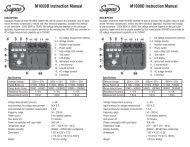
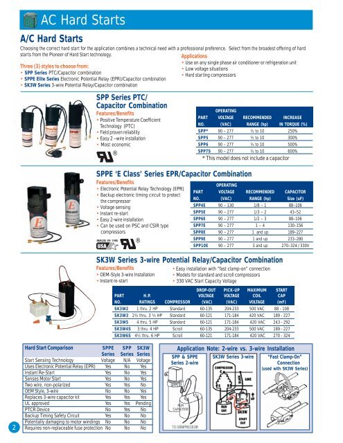
AC Hard StartsA/C Hard StartsChoosing the correct hard start for the application combines a technical need with a professional preference. Select from the broadest offering of hardstarts from the Pioneer of Hard Start technology.Applications• Use on any single phase air conditioner or refrigeration unitThree (3) styles to choose from:• Low voltage situations• SPP Series PTC/Capacitor combination• Hard starting compressors• SPPE Elite Series Electronic Potential Relay (EPR)/Capacitor combination• SK3W Series 3-wire Potential Relay/Capacitor combinationSPP Series PTC/Capacitor CombinationFeatures/Benefits• Positive Temperature CoefficientTechnology (PTC)• Field proven reliability• Easy 2 –wire installation• Most economic®SPPE ‘E Class’ Series EPR/Capacitor CombinationFeatures/Benefits• Electronic Potential Relay Technology (EPR)• Backup electronic timing circuit to protectthe compressor• Voltage sensing• Instant re-start• Easy 2-wire installation• Can be used on PSC and CSIR typecompressors®OPERATINGPART VOLTAGE RECOMMENDED INCREASENO. (VAC) RANGE (hp) IN TORQUE (%)SPP* 90 – 277 ½ to 10 250%SPP5 90 – 277 ½ to 10 300%SPP6 90 – 277 ½ to 10 500%SPP7S 90 – 277 ½ to 10 600%* This model does not include a capacitorSK3W Series 3-wire Potential Relay/Capacitor CombinationFeatures/Benefits• OEM-Style 3-wire Installation• Instant re-startOPERATINGPART VOLTAGE RECOMMENDED CAPACITORNO. (VAC) RANGE (hp) Size (uF)SPP4E 90 – 130 1/8 – 1 88–106SPP5E 90 – 277 1/3 – 2 43–52SPP6E 90 – 277 1/2 – 3 88–106SPP7E 90 – 277 1 – 4 130–156SPP8E 90 – 277 1 and up 189–227SPP9E 90 – 277 1 and up 233–280SPP10E 90 – 277 3 and up 270–324 / 330V• Easy installation with “fast clamp-on” connection• Models for standard and scroll compressors• 330 VAC Start Capacity VoltageDROP-OUT PICK-UP MAXIMUM STARTPART H.P. VOLTAGE VOLTAGE COIL CAPNO. RATINGS COMPRESSOR (VAC) (VAC) VOLTAGE (mF)SK3W2 1 thru. 2 HP Standard 60-135 204-233 500 VAC 88 - 108SK3W3 2½ thru. 3 ½ HP Standard 60-121 171-184 420 VAC 189 - 227SK3W5 4 thru. 5 HP Standard 60-121 171-184 420 VAC 243 - 292SK3W4S 3 thru. 4 HP Scroll 60-135 204-233 500 VAC 189 - 227SK3W6S 4½ thru. 6 HP Scroll 60-121 171-184 420 VAC 270 - 32422Hard Start Comparison SPPE SPP SK3WSeries Series SeriesStart Sensing Technology Voltage N/A VoltageUses Electronic Potential Relay (EPR) Yes No YesInstant Re-Start Yes No YesSenses Motor Start Yes No YesTwo wire, non-polarized Yes Yes NoOEM Style, 3-wire No No YesReplaces 3-wire capacitor kit Yes Yes YesUL approved Yes Yes PendingPTCR Device No Yes NoBackup Timing Safety Circuit Yes No NoPotentially damaging to motor windings No No NoRequires non-replaceable fuse protection No No NoApplication Note: 2-wire vs. 3-wire InstallationSPP & SPPESeries 2-wireSK3W Series 3-wire “Fast Clamp-On”Connection(used with SK3W Series)
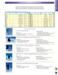
Universal Potential RelaysRelaysNote: See Technical Area for Application Note on RelaysReplacing all potential relays, these WIRE TO WIRE Universal Potential Relays offer the ultimate in convenience. One potential relay to fit any application.Choose to “drop in” the SUPR Universal Potential Relay or “dial in” the exact pick-up voltage for the APR5 Adjustable Potential Relay. State of the Artelectronic circuitry provides Wire to Wire replacement of any potential relay with added motor protection.Applications• Replaces all OEM potential relays• Used on any single phase motor orair conditioning and refrigerationcompressor up to 5 hp.Features/Benefits• Reduces inventory• Accomodates screw-on or push-on connections.• Wire to Wire Replacement for virtually ALL • Dimensions identical to industry standard potential relays.potential relays.• Easy replacement mounting with universal mounting bracket.• Recycles instantly• Start winding protection if motor does not start.• Replaces both 3 and 5 terminal potential relays. • Prevents start capacitor venting when motor doesn’t start.SUPR Universal Potential Relay• Time Function Relay• Start Time: 1.0 - 0.5 secondsAPR5 Adjustable Potential Relay• Adjustable, Voltage Sensitive Relay• Set pick-up voltage• Safety time out 1.0 – 1.5 secondsCommon SpecificationsOperating Voltage 110 – 270 VAC, Single PhaseAmperage30 AMPMotor Power Rating up to 5 hpOperating Position Non-positional mounting.Universal Mounting Allows for easy installation. Unused portionsBracketof the bracket simply snap off with pliers.TerminalsScrew or push-on. Adapters to convertscrew-on to push-on are provided.Dimensions 1.75W x 2.25L x 1.50H90X Series Potential Relays• Meets all requirements ofOEM relays• Universal break-offbracketFeatures/Benefits• 50/60 cycle• Contact rating 35 amp@ 277 VAC• Non-positional• Instructions and wiringdiagram included in eachrelay®CONTINUOUSDROPMODEL COIL PICK-UP OUT REPLACES GE 3ARR3NO. VOLTAGE MIN. MAX. MAX. RELAY GROUPS*9063 170 139 153 55 2J; 2K; 2L; 2M; 5N; 7J; 7K; 7L; 7M; 7N; 8L;8M; 8N9064 395 260 275 120 3A; 3B; 3AV; 3AU; 4A; 4B; 6A; 6B; 6AV; 10A;10B; 10AU; 10AV; 14A; 14B; 16A9065 332 168 182 90 3P; 3R; 3AP; 5P; 5R; 5S; 5T; 13P; 19N; 22S9066 395 215 225 120 3U; 3V; 3AT; 6U; 6V; 6W; 16U9067 420 295 315 125 3C; 3D; 3AA; 4C; 4D; 4BK; 6C; 6D; 6AA; 10C;10D; 26A; 26B; 26C; 26D9068 502 325 345 135 3E; 3F; 3AB; 3AC; 4E; 4F; 4G; 6E; 6F; 6G; 10H;10AB; 10AC; 26E; 26F; 26G; 26H; 27E; 27F; 27G9069 336 180 195 105 3S; 3T; 10S; 10T; 10AS; 13S; 13T; 20S; 25S; 25T9070 253 285 305 77 5B; 5C; 5D; 5AA; 8B; 8C; 8D; 27A; 27B; 27C9071 420 212 232 121 6TV; 6TW; 10V; 16TV; 20V*Determine group from GE part number.903X Series GeneralPurpose Switching RelaysDouble pole – double throw (DPDT)Applications• <strong>HVAC</strong>/ R• Appliance vending machines• Fan controls• Business machines®PART COIL TERMINAL TERMINAL CROSS REFERENCENO. VOLTAGE 1-2-3 4-5-6 ESSEX/RBM HONEYWELL90340 24 power power 90-340 R8222D101490341 110/12 power power 90-341 R4222D101390342 208/240 power power 90-342 R4222N1021POWERPILOTCONTACT 208/240V 208/240VRATINGS 120V 277V 120V 277VFull Load Amps 12 6 - -Resistive Amps* 15 15 3 3Locked Rotor Amps 60 35 - -Horsepower 3/4 3/4 1/10 1/10*0.75 power factor33
<strong>HVAC</strong> - RelaysRelays902XX & 903XX Series General Purpose Fan RelaysEngineering Data• CONTACTS: SPST-NO, SPST-NC, SPDT, 1 NO/1 NC, Material/Power - Silver Alloy, Material 1/2 Pilot - Fine Silver• POWER RATINGS (All Forms): 125 VAC, 18A Resistive, 12FLA, 60 LRA, 240/277 VAC, 18A Resistive, 8 FLA, 48 LRA• SPECIAL POWER RATINGS (Form 1 & 2): 125 VAC, 14FLA, 84 LRA, 277 VAC, 25A Resistive• PILOT RATINGS (All Forms): 3A, 277 VAC Gen. Purpose,250 VA @ 250 VAC, 277 VA @ 277 VAC, 125 VA @ 125VAC• COILS : Voltage Ratings - 24, 120, 208/240, 77 VAC, 12, 24VAC Frequency - 50/60 Hz Pick-up Voltage - AC 85% ofnominal, DC 75% of nominal, Power Ratings -AC DC, Inrush5 VA 3VA, Sealed 3 VA 3 VAPARTCOILNO. DESCRIPTION AMPS VOLTAGE90290 SPST 4 24V90291 SPST 4 120V90292 SPST 4 240V90293 SPDT 1 24V90294 SPDT 1 120V90295 SPDT 1 240V90370 SPDT 12 24V90372 SPDT 12 120V90374 SPDT 12 240V90380 IN/NC 13 24V90382 IN/NC 13 120V90384 IN/NC 13 240VShort Cycle Protector, Time Delay Relay and Contactor Combination• Choose Delay on Break or Delay on Make model• Ideal for split systems not supplied with contactor or timedelay relayFeatures/Benefits• Adjustable Delay• Relay coil same voltage as load• ¼” male quick connect terminals• Encapsulated circuitry• Input Voltage: 208 - 230 VAC• Maximum Amps: 30 A• Prevents short cycling• Contactor takes compressor load off thethermostat circuitPART DELAY DELAYNO. TYPE RANGETDP269 Delay on Make (DOM) 6 sec. to 300 sec.TDC22 Delay on Break (DOB) 1 sec to 350 sec.Facts About CapacitorsCompressor Protection Package CombinationCombines Hard Start Kit with maximum compressor protection.Features/Benefits• Can be installed in pilot circuits for 24 to 288 VAC• Adjustable time delay from 6 seconds to 5 minutes• Operates with or without cooling thermostat anticipator• Only two terminal connection on Time Delay• Can be mounted as an assembly or snapped apart forseparate mounting• Two models available to suit specific requirementsCapacitorsApplications• Residential and commercial PSC A/C units and heatpumps• For all PSC A/C units from 1 H.P. to 10 H.P• Can be used on 115 thru 288 VAC units• For severe low voltage or hard starting compressorsPARTNO. INCREASED TORQUE TIME DELAY RANGESPP5TD 270 ounce inches (300%) 6 sec. to 5 minutesSPP6TD 390 ounce inches (500%) 6 sec. to 5 minutes• Capacitors are rated by microfarads (uF) and voltage. The rated capacitor should not be changed since the motor operates at maximum efficiencywhen using a specified capacitor size. However a plus or minus 10 % rule of thumb applies to the microfarad rating when changing out acapacitor. If necessary, the replacement capacitor voltage rating can be higher than specified, but not lower without effecting the capacitor life.• Always replace the run capacitor when installing a new motor. If a defective capacitor is in the circuit the motor will probably not run. If it does run,it will operate as if it is overloaded. The motor speed will be low; it will overheat and probably activate the motor overload protector causing shortcycling.• Capacitors can hold a charge for long periods of time. To prevent shock the capacitor should be discharged before it is removed. The properprocedure to do this is to use a 5000 to 20000 Ohm bleed resistor.44• To check capacitors, use a SUPCO Capacitor Tester p/n MFD10.
VALUE (UF)VALUE (UF)VALUE (UF)Motor Run CapacitorsFeatures:• Non – PCB biodegradable synthetic oil• Physical interrupter for safety• Operating temperature –13°F to + 185°F(- 25°C to + 85°C)• Microfarad uF tolerance +/- 5 %• Drawn steel case construction• Quad blade quick connect terminals• Hermetically sealedCapacitorsApplications:• Air Conditioning Compressors• Refrigeration Compressors• Furnace Blower Motors• Condenser Fan Motors®RUN CAPACITORSPART NUMBER370 VAC440 VACSINGLEDUALOVALROUNDPART NUMBER370 VAC440 VACSINGLEDUALOVALROUNDPART NUMBER370 VAC440 VACSINGLEDUALOVALROUNDCR2X370 2 X X XCR3X370 3 X X XCR4X370 4 X X XCR5X370 5 X X XCR6X370 6 X X XCR7.5X370 7.5 X X XCR10X370 10 X X XCR12.5X370 12.5 X X XCR15X370 15 X X XCR17.5X370 17.5 X X XCR20X370 20 X X XCR25X370 25 X X XCR30X370 30 X X XCR35X370 35 X X XCR40X370 40 X X XCR45X370 45 X X XCR50X370 50 X X XCR60X370 60 X X XCR70X370 70 X X XCD15+5X370 15+5 X X XCD15+10X370 15+10 X X XCD20+5X370 20+5 X X XCD20+5X370R 20+5 X X XCD20+15X370 20+15 X X XCD25+3X370 25+3 X X XCD25+5X370 25+5 X X XCD25+10X370 25+10 X X XCD30+3X370 30+3 X X XCD30+5X370 30+5 X X XCD30+7.5X370 30+7.5 X X XCD35+5X370 35+5 X X XCD35+7.5X370 35+7.5 X X XCD40+5X370 40+5 X X XCD45+5X370 45+5 X X XCD55+7.5X370 55+7.5 X X XCD60+10X370 60+10 X X XCR15X370R 15 X X XCR20X370R 20 X X XCR25X370R 25 X X XCR30X370R 30 X X XCR35X370R 35 X X XCR40X370R 40 X X XCR45X370R 45 X X XCR50X370R 50 X X XCR55X370R 55 X X XCR60X370R 60 X X XCR70X370R 70 X X XCR80X370R 80 X X XCD20+5X370R 20+5 X X XCD20+7.5X370R 20+7.5 X X XCD25+3X370R 25+3 X X XCD25+4X370R 25+4 X X XCD25+5X370R 25+5 X X XCD30+3X370R 30+3 X X XCD30+5X370R 30+5 X X XCD35+5X370R 35+5 X X XCD40+5X370R 40+5 X X XCD45+5X370R 45+5 X X XCD80+5X370R 80+5 X X XCR2X440 2 X X XCR3X440 3 X X XCR4X440 4 X X XCR5X440 5 X X XCR6X440 6 X X XCR7.5X440 7.5 X X XCR10X440 10 X X XCR12.5X440 12.5 X X XCR15X440 15 X X XCR17.5X440 17.5 X X XCR20X440 20 X X XCR25X440 25 X X XCR30X440 30 X X XCR35X440 35 X X XCR40X440 40 X X XCR45X440 45 X X XCR50X440 50 X X XCR55X440 55 X X XCR60X440 60 X X XCD25+5X440 25+5 X X XCD30+5X440 30+5 X X XCD35+5X440 35+5 X X XCD35+7.5X440 35+7.5 X X XCD40+5X440 40+5 X X XCD40+7.5X440 40+7.5 X X XCD45+5X440 45+5 X X XCD45+7.5X440 45+7.5 X X XCD55+10X440 55+10 X X XCR10X440R 10 X X XCR15X440R 15 X X XCR20X440R 20 X X XCR25X440R 25 X X XCR30X440R 30 X X XCR35X440R 35 X X XCR40X440R 40 X X XCR45X440R 45 X X XCR50X440R 50 X X XCR55X440R 55 X X XCR60X440R 60 X X XCR70X440R 70 X X XCR80X440R 80 X X XCD20+5X440R 20+5 X X XCD25+5X440R 25+5 X X XCD25+7.5X440R 25+7.5 X X XCD30+5X440R 30+5 X X XCD30+7.5X440R 30+7.5 X X XCD35+5X440R 35+5 X X XCD35+7.5X440R 35+7.5 X X XCD35+10X440R 35+10 X X XCD40+5X440R 40+5 X X XCD40+7.5X440R 40+7.5 X X XCD40+10X440R 40+10 X X XCD45+5X440R 45+5 X X XCD45+7.5X440R 45+7.5 X X XCD50+5X440R 50+5 X X XCD50+7.5X440R 50+7.5 X X XCD55+5X440R 55+5 X X XCD55+7.5X440R 55+7.5 X X XCD55+10X440R 55+10 X X XCD60+5X440R 60+5 X X XCD60+7.5X440R 60+7.5 X X X55
CapacitorsMotor Start CapacitorsUL approved Start Capacitors available in 110 VAC, 165 VAC, 220 VACand 330 VAC.Features• Dry, electrolytic, no polarized type for intermittent duty in AC motors and compressors.• Used where starting torques must be higher in relation to running torques.• Moisture and oil resistant molded phenolic resin or plastic material.• Standard dual blade terminals.• Industry standard case sizes.®110 VACPART VALUE CASENO, (UF) SIZECS21-25X110 21-25 1CS25-30X110 25-30 1CS30-36X110 30-36 1CS36-43X110 36-43 1CS43-56X110 43-56 1CS56-72X110 56-72 1CS64-77X110 64-77 1CS72-88X110 72-88 1CS88-108X110 88-108 1CS108-130X110 108-130 1CS124-156X110 124-156 1CS145-175X110 145-175 1CS161-193X110 161-193 1CS189-227X110 189-227 1CS200-240X110 200-240 2CS216-259X110 216-259 2CS233-292X110 233-292 4CS270-324X110 270-324 4CS300-360X110 300-360 4CS324-388X110 324-388 4CS340-408X110 340-408 4CS378-440X110 378-440 4CS400-480X110 400-480 5CS460-552X110 460-552 5CS540-648X110 540-648 5CS590-708X110 590-708 5CS708-850X110 708-850 7CS829-995X110 829-995 8CS1000-1200X110 1000-1200 8165 VAC 220 VACPART VALUE CASEPART VALUE CASENO. (UF) SIZEPART NO. NUMBER (UF) SIZECS124-156X165 124-156 4CS21-25X220 21-25 1CS145-175X165 145-175 4CS25-30X220 25-30 1CS161-193X165 161-193 4CS30-36X220 30-36 1CS233-292X165 233-292 5CS36-43X220 36-43 1CS270-324X165 270-324 5CS43-56X220 43-56 2CS56-72X220 56-72 2CS64-77X220 64-77 4CS72-88X220 72-88 4330 VACCS88-108X220 88-108 4PART VALUE CASECS108-130X220 108-130 4NO. (UF) SIZECS124-156X220 124-156 5CS21-25X330 21-25 1CS145-175X220 145-175 7CS25-30X330 25-30 1CS161-193X220 161-193 7CS30-36X330 30-36 4CS189-227X220 189-227 7CS36-43X330 36-43 4CS216-259X220 216-259 8CS43-56X330 43-56 4CS233-292X220 233-292 8CS53-70X330 53-70 5CS270-324X220 270-324 8CS56-72X330 56-72 5CS72-88X330 72-88 5CS88-108X330 88-108 7CS108-130X330 108-130 8CS124-156X330 124-156 8CS130-156X330 130-156 8CS145-175X330 145-175 8CS161-193X330 161-193 8CS189-227X330 189-227 8CS216-259X330 216-259 8CS270-324X330 270-324 8CS324-388X330 324-388 8Case DimensionsCASESIZE DIAMETER HEIGHT1 1-716" 2-3/4"2 1-7/16" 3-3/8"4 1-13/16" 3-3/8"5 1-13/16" 4-3/8"6 2-1/16" 3-3/8"7 2-1/16" 4-3/8"8 2-9/16" 4-3/8"Wiring Diagramsfor Run Capacitors66
GE Definite Purpose ContactorsFeatures/Benefits• Designed to control air conditioning, refrigeration and resistance heating loads.• Ranges: 20 to 90 Full Load Amps (FLA)• Poles: 1-1/2 to 3• Coil Voltages: 24, 120, 208/240 & 480• Universal mounting base allows easy replacement of other manufacturer’s devices(refer to SUPCO Contactor cross-reference).• Molded enclosed, replaceable coil structures.• Optional field installed auxiliary contacts available.Contactors®CR453C Series Coil Selection.Part No Digit 9 Denotes Coil VoltageCR453C Series20-to 40 Full Load Amps/ 1.5 & 2 polesFeatures• The coil and each power pole are suppliedwith two ¼” quick connect terminals.• Standard 20 – 30 FLA contactors featurehex screws with #2 Phillips / slottedheads.• Standard 40 FLA contactors include boxlugs.PART NO. DIGIT H A B FCOIL VOLTAGE 60 Hz 24 110-120 208-240 277COIL VOLTAGE 50 Hz 24 110-120 208-240 ***FULL RESISTIVE LRA SINGLE PHASE 50/60 HzPART LOAD AMPS 240/ COILNO. POLES AMPS PER POLE 277V 480V 600V VOLTAGECR453CB3HAA 1.5 25 35 150 125 100 24CR453CB3AAA 1.5 25 35 150 125 100 120CR453CB3BAA 1.5 25 35 150 125 100 208/240CR453CC3HAA 1.5 30 40 180 150 120 24CR453CC3AAA 1.5 30 40 180 150 120 120CR453CC3BAA 1.5 30 40 180 150 120 208/240CR453CA2HAA 2 20 30 120 100 80 24CR453CA2AAA 2 20 30 120 100 80 120CR453CA2BAA 2 20 30 120 100 80 208/240CR453CB2HAA 2 25 35 150 125 100 24CR453CB2AAA 2 25 35 150 125 100 120CR453CB2BAA 2 25 35 150 125 100 208/240CR453CC2HAA 2 30 40 180 150 120 24CR453CC2AAA 2 30 40 180 150 120 120CR453CC2BAA 2 30 40 180 150 120 208/240CR453CE2HBB 2 40 50 240 200 160 24CR453CE2ABB 2 40 50 240 200 160 120CR453CE2BBB 2 40 50 240 200 160 208/240CR453A Series25 to 0 Full Load Amps/ 3 PoleFeatures• 3 pole contactors• The coil and each power poleare supplied with two ¼” quickconnect terminals.• Standard 25 and 30 FLAcontactors feature hex screwswith #2 Phillips / slotted headsand short covers.• Standard 40 FLA contactorsinclude box lugs and longcovers.FULL RESISTIVE THREE PHASE 50/60Hz SINGLE PHASE 50/60 HzPART LOAD AMPS 240V 480V 600V HP@ HP@ COILNO. AMPS PER HP/LRA HP/LRA HP/LRAv 20V 24V VOLTAGECR453AB3HAA 25 35 7.5 / 150 10 / 125 10 / 100 2 3 24CR453AB3AAA 25 35 7.5 / 150 10 / 125 10 / 100 2 3 120CR453AB3CAA 25 35 7.5 / 150 10 / 125 10 / 100 2 3 480CR453AB3BAA 25 35 7.5 / 150 10 / 125 10 / 100 2 3 208/240CR453AC3HAA 30 40 10 / 180 15 / 150 15 / 120 2 5 24CR453AC3AAA 30 40 10 / 180 15 / 150 15 / 120 2 5 120CR453AC3CAA 30 40 10 / 180 15 / 150 15 / 120 2 5 480CR453AC3BAA 30 40 10 / 180 15 / 150 15 / 120 2 5 208/240CR453AD3HBB 40 50 10 / 240 20 / 200 20 / 160 3 7.5 24CR453AD3ABB 40 50 10 / 240 20 / 200 20 / 160 3 7.5 120CR453AD3CBB 40 50 10 / 240 20 / 200 20 / 160 3 7.5 480CR453AD3BBB 40 50 10 / 240 20 / 200 20 / 160 3 7.5 208/240CR453A Coil Selection.Part Number Digit 9 Denotes Coil Voltage*For other contactors, configurations and accessories, contact SUPCO.PART NO. DIGIT E H A B F C DCOIL VOLTAGE 60 Hz 12 24 110-120 208-240 277 460-480 575-600COIL VOLTAGE 50 Hz 12 24 110-120 208-240 *** 380-415 550-60077
ContactorsCR353 (F&E) Series CoilSelection.Part Number Digit 10Denotes Coil VoltageCR353 Series50 to 90 Full Load Amps / 3 PoleFeatures• The standard CR353 contactors in the 50–90 FLA ratings are supplied with box lugterminals.• Power poles in the 50 – 90 FLA sizes aresupplied with two ¼” quick connectterminals.• Coils are provided with screw connectionswith a single ¼” quick connect terminal onthe 50 and 60 FLA size and two ¼” quickconnect terminals on the 75 and 90 FLAsize.PART NO. DIGIT H A B F C DCOIL VOLTAGE 60 Hz 24 110-120 208-240 277 460-480 440COIL VOLTAGE 50 Hz 24 110-120 208-240 *** 575-600 550FULL RESISTIVE LRA THREE PHASE 50/60 HzPART LOAD AMPS/ COILNO. AMPS POLE 240V 480V 600V VOLTAGECR353FE3BH1 50 62 300 250 200 24CR353FE3BA1 50 62 300 250 200 120CR353FE3BB1 50 62 300 250 200 208/240CR353FF3BH1 60 75 360 300 240 24CR353FF3BA1 60 75 360 300 240 120CR353FF3BB1 60 75 360 300 240 208/240CR353EG3BH1 75 90 450 375 300 24CR353EG3BA1 75 90 450 375 300 120CR353EG3BB1 75 90 450 375 300 208/240CR353EH3BH1 90 90 540 450 360 24CR353EH3BA1 90 90 540 450 360 120CR353EH3BB1 90 90 540 450 360 208/240Field Installed Auxiliary ContactsPART USE w/SUPCO FULLApplication NoteThe contactor is the primary controller in a coolingcontrols circuit. It is the switching device which activatesthe compressor motor to pump refrigerant through thesystem to provide cooling.Contactors are used to break the power supply to thecompressor. Either 1 or 2 poles are needed for singlephase; 2 or 3 poles for 3 phase motors. Auxiliarycontacts may be used for interlock switching, fan loadsor crankcase heaters. If the contactor is selected withan adequate current rating, the condenser fan may alsobe wired in parallel with the compressor. Then thecondenser fan is energized whenever the compressoris powered.Checking Contactor Operation:• Check contactor operation by switching thecontactor from the system controls.• Make sure that the pressure and overload controlscan break the system circuit to prevent contactoroperation, if necessary.• Check electrical conductance of the contacts.• Check the voltage source to the coil.8 8NO. CONTACTORS SERIES LOAD AMPS POLES DESCRIPTIONCR453XC211 CR453A 25-40 2-3 250V Side Mounted SPDTCR453XC222 CR453A 25-40 2-3 250V Side Mounted Two SPDTCR453XC611 CR453A 25-40 2-3 600V Side Mounted 1 NO - 1 NCCR453XM602 CR453A 25-40 2-3 600V Side Mounted 2 NOCR353XAAA CR353F 50-60 3 250V SPDTCR353XAAB CR353E 75-90 3 250V SPDT
Contactors<strong>Supco</strong> Brand Definite Purpose Contactors®1.5 POLEPART NO. FLA COIL VOLTAGEDP25241 25 24DP2<strong>51</strong>201 25 120DP252401 25 240DP30241 30 24DP301201 30 120DP302401 30 2402 POLEPART NO. FLA COIL VOLTAGEDP20242 20 24DP201202 20 120DP202402 20 240DP25242 25 24DP2<strong>51</strong>202 25 120DP252402 25 240DP30242 30 24DP301202 30 120DP302402 30 240DP40242 40 24DP401202 40 120DP402402 40 240Field Installed SPDT Auxiliary ContactsPART NO. USED WITHAUX506050 & 60 ContactorsAUX759075 & 90 Conatctors<strong>Supco</strong> Brand Contactor Cross Reference3 POLEPART NO. FLA COIL VOLTAGEDP25243 25 24DP2<strong>51</strong>203 25 120DP252403 25 240DP30243 30 24DP301203 30 120DP302403 30 240DP40243 40 24DP401203 40 120DP402403 40 240DP50243 50 24DP501203 50 120DP502403 50 240DP60243 60 24DP601203 60 120DP602403 60 240DP75243 75 24DP7<strong>51</strong>203 75 120DP752403 75 240DP90243 90 24DP901203 90 120DP902403 90 240Contactor NomenclatureExample: DP30242DP = Definite Purpose30 = Full Load Amps24 = Coil Voltage2 = # Of PolesPART DIVERSITECH FURNAS GE GLOBAL HONEYWELL MA LINE MARS PACKARD /NO. CUTLER HAMMER POWER PRO SQUARE D FASCODP25241 *** 45DG10AJD8A CR353CB3AH1 4140 DP1025A5005 *** *** 1S25ADP2<strong>51</strong>201 *** 45DG10AFD8A CR353CB3AA1 4141 DP1025B5046 *** *** 1S25BDP252401 *** 45DG10AGA CR353CB3AB1 4142 DP1025C5045 *** *** 1S25CDP30241 *** 45EG10AJA CR353CD3AH1 4143 DP1030A5013 *** 13067/13101 1S30ADP301201 *** 45EG10AJA CR353CD3AA1 4144 DP1030B5020 *** 13068 1S30BDP302401 *** 45EG10AGA CR353CD3AB1 4145 DP1030C5029 *** 13069 1S30CDP20242 *** 45CG20AJ CR353CA2AH1 4101 DP2020A5021 *** 13071 2S20ADP201202 *** 45CG20AF CR353CA2AA1 4102 DP2020B5038 *** 13072 2S20BDP202402 *** 45CG20AG CR353CA2AA1 4103 DP2020C5037 *** 13073 2S20CDP25242 DP25224 45DG20AJ CR353CB2AH1 4104 *** *** 13077 ***DP2<strong>51</strong>202 DP252120 45DG20AF CR353CB2AA1 4105 *** *** 13078 ***DP252402 DP252240 45DG20AG CR353CB2AB1 4106 *** *** 13079 ***DP30242 DP30224 45EG20AJ CR353AC2AH1 4107 DP2030A5004 8910DP32V14 14321/13104 C2S30ADP301202 DP302120 45EG20AF CR353AC2AA1 4108 DP2030B5003 *** 14322 C2S30BDP302402 DP302240 45EG20AG CR353AC2AB1 4109 DP2030C5002 *** 14323 C2S30CDP40242 DP40224 45GG20AJ CR353AD2BH1 4161 DP2040A5003 8910DP42V14 14421 C2S40ADP401202 DP402120 45GG20AF CR353AD2BA1 4162 DP2040B5002 *** 14422 C2S40BDP402402 DP402240 45GG20AG CR353AD2BB1 4163 DP2040C5001 *** 14423 C2S40CContactor Cross Reference Continued On Next Page99
Contactors<strong>Supco</strong> Brand Contactor Cross ReferencePART DIVERSITECH FURNAS GE GLOBAL HONEYWELL MA LINE MARS PACKARD /NO. CUTLER HAMMER POWER PRO SQUARE D FASCODP25243 *** 42AF35AJ CR353AB3AH1 4110 DP3025A5003 *** 13001 3M25ADP2<strong>51</strong>203 *** 42AF35AF CR353AB3AA1 4111 DP3025B5002 *** 13002 3M25BDP30243 DP30324 42BF35AJ CR353AC3AH1 4113 DP3030A5003 8910DPA33V14 14331/13007 C3M30ADP301203 DP303120 42BF35AF CR353AC3AA1 4114 DP3030B5002 8910DPA33V02 13008 C3M30BDP40243 DP40324 42CF35AJ CR353AD3BH1 4116 DP3040A5002 8910DPA43V14 14431/13013 C3M40ADP401203 DP403120 42CF35AF CR353AD3BA1 4117 DP3040B5001 8910DPA43V02 13014 C3M40BDP50243 DP50324 42DF35AJ CR353FE3BH1 4128 DP3050A5001 8910DPA53V14 13200 C3L50ADP501203 DP503120 42DF35AF CR353FE3BA1 4129 DP3050B5000 8910DPA53V02 13201 C3L50BDP502403 DP503240 42DF35AG CR353FE3BB1 4130 DP3050C5009 8910DPA53V09 13202 C3L50CDP60243 DP60324 42EF35AJ CR353FF3BH1 4131 DP3060A5000 8910DPA63V14 13220 C3L60ADP601203 DP603120 42EF35AF CR353FF3BA1 4132 DP3060B5009 8910DPA63V02 13221 C3L60BDP602403 DP603240 42EF35AG CR353FF3BB1 4133 DP3060C5008 8910DPA63V09 13222 C3L60CDP75243 DP75324 42FE35AJ CR353EG3BH1 4134 DP3075A5008 *** 13240 C3L75ADP7<strong>51</strong>203 DP753120 42FE35AF CR353EG3BA1 4135 DP3075B5007 *** 13241 C3L75BDP752403 DP753240 42FE35AG CR353EG3BB1 4136 DP3075C5006 *** 13242 C3L75CDP90243 DP90324 42GE35AJ CR353EH3BH1 4137 *** *** 13260 C3L90ADP901203 DP903120 42GE35AF CR353EH3BA1 4138 *** *** 13261 C3L90BDP902403 DP903240 42GE35AG CR353EH3BB1 4139 *** *** 13262 C3L90C“Partial Cross Reference”, refer to product sheet for complete cross reference informationSurge ArrestorsSurge ProtectionLIGHTNING is the most obvious source of a power surge, but not the only culprit. Utility Events, Cycling of Air Conditioners, Generators, and Motorscan also produce damaging surges. Protect your equipment with SUPCO’s Surge Arrestors. With a full product line, we can protect all of yourequipment.These devices do not protect electronic appliances such as TV’s, computers, micowaves, etc. They only protect dedicated electromechanical devicessuch as air conditioners. If whole house protection is required use SUPCO p/n DTK-WH5. Which will protect AC power, coaxial and two telephone lines.®Benefits• Easy Installation at Disconnect or Panel• Weatherproof Housing• Indicator Light on some models for Surge Protection Present• Promote Additional Profits• Reduce Callbacks• Keep Equipment RunningSCM1SCM1, SCM & SCMPLUS Surge ArrestorsSurge Protection for:• Air Conditioners • Refrigeration Systems • Furnaces• Air Handlers • Heat Pumps • Electro-Mechanical Devices• Motors• PumpsSCMPLUSSCMPLUGProviding the same protection of the SCM in a convenient, single outlet plug. Plug the SCMPLUG into an outlet, thenplug your sensitive equipment into the SCMPLUG for surge protection!1010Refer to and abide by all Local and State Electrical Codes for proper installation of these devices.
Surge ProtectionDTK-240 & 480-3CMPLUS 3 Phase Surge Arrestors• 208, 240, 480 volt three phase • 50,000 amp surge current, per phase • Limited lifetime warrantyDTK-240-3CMPLUSSpecificationsDTK-240-3CMPLUSDTK-480-3CMPLUSService Voltage 240 VAC 3 phase 480 VAC 3 phaseMax. Surge Current 50,000 Amps 50,000 AmpsContinuous Current Unlimited UnlimitedMax. Energy Dissipation 660 Joules 1740 JoulesMCOV 250 VAC (L-G) <strong>51</strong>0 VAC (L-G)AC Protection Modes L-L, L-G L-L, L-GResponse Time < 5ns Installed, < 5ns Installed,
Specifications*Any other DTK Surge Arrestor Available by Special Order.Surge ProtectionDTK-WH5 Whole House Kit• Complete residential package with AC power, coaxial and 2 telephone line protection• Most comprehensive and cost effective home/home office protection on the market• Full diagnostics on main AC panel unit• This kit includes a DTK120/240HD Series II, DTK-2LVLPSCP-RUV and a DTK-VSP-ADTK-120HW DTK-120/240SA DTK120S15A DTK-WH5Service Voltage 110/125 VAC 120/240 VAC 120 VAC N/AMax. Surge Current 22,500 Amps 200,000 Amps 39,000 Amps N/AContinuous Current Unlimited (Parallel Installation) Unlimited 15 Amps N/AMax. Energy Dissipation 190 Joules 2640 Joules 480 Joules N/AMCOV 130 VRMS/185VPK 250VAC L-N, 500VAC L-L 130 VRMS/185 VPK N/AAC Protection Modes L-N, L-G, N-G L-G, L-L L-N, L-G, N-G N/AResponse Time < 5ns Installed, < 5ns < 5ns N/A
Motor ProtectionTPMP2TPMPU1414Compact Three Phase Motor ProtectorFeatures & Benefits• Low cost three phase motor protection• Easy Installation• Compact design• Monitors and protects against phase loss andphase imbalance only• Operating Temperature -40°F to +167°F(-40°C to + 75°C)• 1/4” male spade terminal connectionsSequence of OperationThe TPMP series will disconnect the motor pilot when the monitored problem isdetected. The TPMP series will only re-energize the circuit when all 3 phases areactivated at the full voltage ratings and the delay on make time has elapsed. TheTPMP2 does not have a time delay feature.Universal Three Phase Motor ProtectorFeatures & Benefits• Low cost Universal three phase motor protection• Easy Installation• Minimizes inventory• Monitors and protects against phase loss, reversal and imbalance• Response time 80 milliseconds maximum• Bright LED for on and fault indications* The bypass time shouldbe longer then the TPMPUtime delayLight Duty Commercial TimersElectronic Adjustable TimersFeatures• Adjustable Interval Timers• LED to indicate energized load• Fast cycle button to alternate timer manually• Automatic cycle is between 40 to 60 seconds• Timer reset connection for external reset control• Replaces most mechanical commercial timers• Mounted using # 6 screws (not included)• Available in 120 Volts or 220 VoltsApplications• <strong>HVAC</strong>/R Motors and Pumps• <strong>HVAC</strong>/R Compressors• Protects Scroll and screw compressors from reverse rotation• Material Handling Equipment (Overhead Electric Crane Motors)• Elevator Motors• UtilitiesTPMP2Input Line Voltage 208 - 277 VACControl Voltage18 - 240 VACFrequency50/60 HzImbalance Fixed 7%Total Power Consumption 3 VA MaximumContact TypeN.O. & N.C. Type CResistive5 AMP 240 VAC/10 AMP 120 VACFire Resistive Plastic UL-94 VODimensions2.35” x 2.43” x 1.1” (59.7 x 61.7 x 27.9 mm)Weight2 oz. (54 gr)Applications• Defrost Heaters• Water Heaters• Operating Temperature -40°F to +167°F(-40°C to + 75°C)• 1/4” male spade terminal connections• Delay on make timer• Adjustable 10 seconds to 5 minutes• Tolerance +/- 20%TPMPUInput Line Voltage 180 - 600 VACControl Voltage 18 - 240 VACFrequency50/60 Hz (cut wire for Hz)Imbalance Adjustable +/-40 to 20%Total Power Consumption 3 VA MaximumContact Ratings 10 AMP SPDTResistive10 AMP 240 VAC, 12 AMP 120 VAC/24 VACInductive 4.5 AMP 230 V- Cos. 0 0.6Fire Resistive Plastic UL-94 VODimensions5.35” x 3.68” x 1.26” (136 x 93.5 x 32 mm)Weight6.35 oz. (180 gr)• Indoor or Outdoor Lighting Systems• Motors• PumpsCommon Specifications for EDT12 and EDT13On Time5 to 60 MinutesOff Time1 to 27 HoursTiming Accuracy +/- 10%Fast CycleApproximately 30 SecondsMAXIMUM MAXIMUM NO. OFPART OPERATING MOTOR SWITCHING SWITCHING CURRENT Set OFNO. VOLTAGE CAPACITY, HP (RESISTIVE), AMP CONTACTSEDT12 120 1 27 1EDT12-20 220 2 25 1EDT13 120 1 27 2EDT13-20 220 2 25 2
TimersMechanical Defrost ControlsFeatures• Dial: 24 Hour, with inner dial adjustable for defrost and 5 dial pins.• Defrost Frequency: Adjustable from 1 t o 6 cycles per day; minimum of 4 hours between successive defrost cycles.• Defrost Duration: Adjustable from 4 to 110 minutes in 2 minute increments.• Switch Rating: 40 amps resistive, 2 HP per pole, 690 VA pilot duty, 120 – 240 volts AC.• Enclosure: Heavy steel NEMA1 indoor enclosure with knockouts at bottom, back and sides. Spring hasp, with hole for a6041061410lock, holds permanently attached, side hinged door.Applications• Commercial freezer and cooler evaporatorsAccessoriesX6000 - Trippers (5 per package)• 6040 Contact Arrangement: Choice of four contactarrangements for electric heat, hot gas, orcompressor shut down defrost.• Time Initiated - Time Terminated• 6140 Contact Arrangement: Choice of three contactarrangements for electric heat, hot gas or compressorshut down defrost.• 6140 Defrost Termination: For use with externaltemperature or pressure sensor. Inner dial provides backup defrost termination and protects against sensormalfunction.• Time Initiated - Time TerminatedGeneral Purpose 24 Hour Mechanical TypeCD101Features• Dial: 24 hour, 2 on and 2 off trippers• Switch Rating: 40 amps resistive or tungsten, 1000 VA pilot duty, 2 HP and 120 or 240 volts.• Operations: Up to 10 ON/OFF operations per 24 hours. With manual ON/OFF switch that allows circuit to be hand operatedwithout disturbing scheduled setting.• Minimum Setting: 1 hour between On/OFF, 2 hours between OFF/ON.• Enclosure: Non corrosive NEMA 1CD100 SeriesApplications• Pool filter pumps• Pool heaters• Indoor and outdoor lighting systems• Sprinkler systemsUniversal Defrost Timers/Temporary ControlSA1005 Defrost TimerFeatures/Benefits• Allows normal refrigerator defrost operationwhen icemaker is removed from system.• Direct "plug-in" fit with either suction cup orpermanent screw-mounting.6040 Series Mechanical Defrost ControlNORMAL POSITIONS OF CONTACTSDURING REFRIGERATION CYCLEREPLACES VOLTS CONTACT CONTACT CONTACTSPART NO. PARAGON 60 Hz. N-3 1-3 2-460410 8041-00 120 closed open closed604120 8041-20 208-240 closed open closed60450 8045-00 120 none open closed604520 8045-20 208-240 none open closed6140 Series Mechanical Defrost ControlREPLACES VOLTS CONTACT CONTACT CONTACTSPART NO. PARAGON 60 Hz. N-3 1-3 2-461410 8141-00 120 closed open closed614120 8141-20 208-240 closed open closed61450 8145-00 120 none open closed614520 8145-20 208-240 none open closedAccessoriesX100 - Trippers (2 per package)REPLACESPART NO. PARAGON VOLTS SWITCH ENCLOSURECD101 4001-00 120 SPST NEMA1CD104 4004-71 240 DPST NEMA1Applications• Fits All Whirlpool & SearsRefrigerators with Flexible TrayIcemakers®®SC1002 Temporary Cold ControlFeatures/Benefits• Temporary Emergency Universal Replacement• Keeps Equipment Up & Running Until Exact Replacementor Permanent Control Is Installed• SC1002 Can Be Used As Permanent Control• Three Mounting Options Available Suction Cup,Velcro or Screw Mounting• Safe & Easy InstallationApplications• Domestic & Commercial Refrigerators & FreezersPART NO. TEMP. RANGE DIFF °F SWITCHSC1002 -6°F to +40°F 7° SPST1<strong>51</strong>5
Timers1616EDT Series Electronic Adjustable Defrost TimerFeatures/Benefits• Universal Replacement• Electronic Circuitry• Adjustable Defrost Frequency 4 to 12 Hours• Adjustable Defrost Time 10 to 35 Minutes• Available in 115 & 208/240 Volts• Standard Size & Mounting To Fit Most Applications• Standard Terminal Configuration To AccommodateMost Connections• No Ground Wire• Dust Proof Case• Quiet Operation & DurabilityApplications• Replaces Most Defrost Timers In Domestic & Commercial Refrigerators & FreezersSpring Wound TimersFeatures• Spring wound by turning the dial for the desired amount of time• Commercial Grade Brushed Aluminum Cover Plate• SPST switch• Switch circuit is in open position at the end of the timing cycle.• Designed to fit in any single gang electrical boxApplications• Heaters• Fans• Indoor & Outdoor Lights• Pool & Spa Equipment5000 Series Multi Circuit Defrost ControlsThese accurate multi-circuit timing devices can individually operate from 1 to 24 switches.Features• Field adjustable defrost control combines ease of programming with accuracy and reliability.• Positive snap acting switches to provide positive and immediate switching.• Time Cycle: Adjustable in 2 minute increments from 2 to 120 minutes.• Motor: Synchronous type, completely sealed and lubricated.• Motor Power: 4 watts• Motor Temperature Range: (Ambient): +35°F to +175°F• Base: All steel construction, 16 gauge-channeled steel.Zinc plated for corrosion resistance and durability.• Contact Transfers: Maximum number of contacttransfers per 24-hour period for each programtimer is 64 (8-switch unit) or 32 (4-switch unit).• Terminals: ¼ inch male quick connect (standard).ApplicationsThe 5000 series controls are designed to control aseries of operations with a variable time sequence;such as a refrigerator defrost cycle.*For wiring accessories refer to pages 102-106 Terminals & Connectors.PARTMAX. COMPRESSOR MAX. RESISTIVENO. VOLTAGE RATING LOADEDT10 115 VAC 1/3 HP 10 AmpEDT20 208/240 VAC 1/3 HP 5 AmpEDT11 115 VAC 3/4 HP 20 AmpEDT21 208/240 VAC 3/4 HP 20 Amp®Optional AccessoriesWH3 - Three wire adapter kitWH4 - Four wire adapter kit®Ratings(Applies to all models)• 20 amps / 125 VAC / 1HP• 10 amps / 250 VAC / 1 HP• 10 amps / 277 VAC / 1HP• 7 amps / 125 VAC Tungsten / 1 HPPART TIME SWITCHNO. REPLACES RANGEPM15M MH Rhodes - SW15M 0-15 min. SPSTPM30M MH Rhodes - SW 30M 0-30 min. SPSTPM60M MH Rhodes - SW60M 0-60 min. SPSTPART NO. OF NO. OFNO. VOLTS Hz SWITCHES MOTORS50100B 120 60 8 250103B 240 60 8 25011 Slave Slave 8 Slave5014 Slave Slave 4 Slave50150B 120 60 4 250153B 240 60 4 2
TD Series Time DelaysStandard Features / Specifications• Three styles available: Delay on Make, Delay on Break & By – Pass• Fixed or adjustable delay ranges• Initiate timer in 70 milliseconds• Broad input voltage range (Pilot Circuit)19 to 250 VAC/VDC, 50/60 Hz (TD60, TD70 TD32)19 to 130 VAC/VDC, 50/60 Hz (TD74)• Maximum load 1.0 amp, 10 amp inrush• Varying models work with or without anticipator type thermostats• Terminal or wire connections availableTime Delays• Operating Temperature Range 0°F to +160° F (-18°C to +71°C)• Compact Size 2” x 2” x .075” (5.08 x 5.08 x 1.9 cm)• Non positional single hole mounting• All parameters are subject to change as per special requirements• By – pass a control or device during start up• Helps to reduce power surges in multiple compressor applicationsGeneral Applications• Protection from short cycling of compressor• Ideal for compressor stagingTD60 SeriesDelay on Make Timers (DOM)Mode of Operation• Upon application of power the time delay initiates. Oncompletion of selected delay period, the load is energized.Timer will reset on power interruption or when thermostatdisconnects.Timing DiagramDELAY RANGE DELAY RANGEPART NO. ADJUSTABLE FIXED (min) CONNECTIONS REPLACESTD68** 6 sec to 8 min n/a 2 - 1/4" male terminals Diversitech AC-800-ADM1 /ICM 105 / A-1 706 / Mars 32391TD69* 6 sec to 8 min n/a 2 - 1/4" male terminals Diversitech AC-800-ADM1 /ICM 102 / A-1 701 / Mars 32391TD69W* 6 sec to 8 min n/a 2 - 6" long wire leads*Cut the jumper to use in 120/240 volts. **The TD68 is not for use with a cooling anticipator.TD70 / TD74 SeriesDelay on Break Timers (DOB)Mode of Operation• Upon application of power the load is energized immediately.When the thermostat opens or on power interruption the loadis de-energized and the time delay initiates. The load will beenergized again after the delay time has elapsed.Timing DiagramDELAY RANGE DELAY RANGEPART NO. ADJUSTABLE FIXED (min) CONNECTIONS REPLACESTD72** 6 sec to 5 min n/a 2 - 1/4" male terminals Diversitech ASC500-ADB1 /ICM203 / Mars 32392 / A-1 EAC-501-ADJTD73* 6 sec to 5 min n/a 2 - 1/4" male terminals Diversitech ASC500-ADB1 /ICM203 / Mars 32392 / A-1 EAC-501-ADJTD73W* 6 sec to 5 min n/a 2 - 6" long wire leadsTD74 6 sec to 5 min n/a 4 -1/4” male terminals ICM203 / Mars 32382 / A-1 EAC-426-300*Cut the jumper to use in 120/240 volts. **The TD72 & TD74H is not for use with a cooling anticipator.TD32 By Pass TimerOn Delay Interval Timer /Normally Closed Delay on Make (DOM)Mode of Operation• With the power applied to the input the load is energizedimmediately and remains energized for the length of the timedelay regardless of the state of the switch being bypassed.This timer is essential for bypassing low-pressure controlsand switches during cold start up conditions.®Timing DiagramDELAY RANGEPART NO. ADJUSTABLE CONNECTIONS REPLACESTD32 10 - 1,000 seconds +/- 20 % 2 - 1/4" male terminals ICM175 / Mars 3239<strong>51</strong>717
<strong>HVAC</strong> - Commercial TimersMotorsVentilator MotorsSM550 Series Ventilator MotorsFeatures/Benefits• Exact Replacement for Nutone Range Hood Ventilators• C Frame Design• SM550 Motor includes FB460 ImpellerSee page 121 for Motor RotationApplications• Range Hoods• Bathroom Exhaust Fans®PART SHAFT NUTONE ROBERTSHAWNO. SPEED RPM DIMENSIONS ROTATION STACK LEAD NO. NO.SM550 1 3000 7/32" X 1 3/4" CCW 1/2” 120 V Plug C65878 33-100SM5<strong>51</strong> 2 High 3000 7/32" X 1 7/16" CW 7/8” 2 Speed Plug C52367 33-101Low 1640SM552 1 3000 7/32" X 1 1/4" CCW 3/4” 120 V Plug C63675 33-103SM553 1 3000 7/32" X 1 3/4" CCW 3/4” Eyelet C66582 33-104SM554 2 High 3300 7/32" X 1 7/16" CCW 7/8” 2 Speed Plug C27987 33-105Low 3200SM555 1 3000 7/32" X 2 3/8" CCW 5/8” 120 V Plug C68627 33-106SM556 1 3000 7/32" X 1 7/8" CCW 5/8” 120 V Plug C34484 N/A®Evaporator Fan Motors®SM700 Series VentilatorMotorsFeatures/Benefits• Exact Replacement for Broan Ventilators• C Frame Design• 120 Volts / 60 Hz• CCW Rotation• Multi Fit To Work WithOther Brand VentilatorsFeatures/Benefits• Prefastened Multi Fit, Break Off Mounting Bracket• Break Off 2” Motor Shaft with Breakaways at ½” and 1-1/2”• Includes All Mounting Accessories and Hardware• Reversible Rotation• Single Speed• Shaft Diameter 1/8”PARTNO.SM999SM998Tech Tips• “F” suffix on shaft length indicates flat on shaft.• “S” suffix indicates spline shaft.• When replacing a motor make sure that the type, voltage,amperage, wattage, rotation, shaft size, stack size and theelectrical connectors are the same as the original motor.PART SHAFT SHAFT PLUG REPLACESNO. SPEED DIA. STACK LENGTH TYPE BROAN NO.SM700SM701SM702SM703SM704SM7052111117/32"1/4"1/4"5/32"7/32".181"3/4"7/8"7/8"1/2"7/8"5/8"1 1/4" F2 3/4" F2 3/4" F1 3/4" S1 1/4" F1 1/2" F3 PIN2 PRONG5 PIN2 PRONG2 PRONG2 PRONG990802189908015999080160990802459908016699080216SM999 Universal Evaporator Fan Motor Kit – 120 VACSM998 Universal Evaporator Fan Motor Kit – 220 VACFeatures/Benefits• Includes the same Features / Benefits, Applications andSpecifications as the SM999, except it operates on 220 VAC 50/60 Hz.• Direct Replacement for the Mars 90998DESCRIPTIONApplications• Replaces Over 450 Different EvaporatorType Motors.• Direct Replacement For The GEM 240Series, Mars 90999 and Robertshaw 33-110, 33-112 & 33-114.120 VAC, 3000 RPM, 1/200 H.P., .31 AMP impedance protected220 VAC, 3000 RPM, 1/200 H.P., .31 AMP impedance protected1818SM999BRKTSM999/SM998 Kit Replacement Motor Bracket
SpecificationsSM140-40A Blower Fan AssemblyFeatures/Benefits• Direct replacement kit for Nutone bath fans• Replaces Nutone motor p/n K5895 and kit p/n K5894Exact Replacement & Utility MotorsSM600 Series Utility Motor KitsFeatures/Benefits• Versatile replacement for all “C” Frame and “3 1/2” RoundStyle motors• Impedance Protected• SM670, SM672 and SM673 include fan blades FB402 andFB550• SM675 is thermal protected• Available in sleeve or ballbearing design• SM675 includes fan blade FB550 only• Motor Kits include complete hardware and mounting kitsMotorsPARTNO. SPEED RPM VOLTS AMPS ROTATION NUTONESM140-40A 1 2400 115 0.9 CCWSE K5894 Motor KitK5895 Motor OnlyPART CURRENT SHAFT STACK ROTATION REPLACES REPLACES REPLACESNO. TYPE VOLTS AC RPM (AMPS) DIMENSIONS SIZE (REVERSIBLE) ACME MIAMI BOHN ROBERTSHAW MARSSM670 a Sleeve 120 3000 0.55 3/16" X 1-1/4" 5/8" CW/CCW 600, 700, 14001 90971710, 4670SM671 Sleeve 120 3000 0.55 3/16" X 1-1/4" 5/8" CW/CCW 14003SM672 a Sleeve 240 3000 0.32 3/16" X 1-1/4" 5/8" CW/CCW 602, 702, 4672 14005 90982SM673 a Sleeve 120 3000/1550 .55/.34 3/16" X 1-1/4" 5/8" CW/CCW 4673 14007SM674 Sleeve 120 3000 0.55 3/16" X 1-1/4" 5/8" CW/CCW 14009SM675 b Sleeve 120/240 3000 1.0/.50 3/16" X 2-3/8" 1" CW/CCW 7502 90970SM676 Sleeve 120 3000 0.5 3/16" X 1-1/4" 7/8" CW/CCW 780 14011SM677 Sleeve 120 2000 0.33 3/16" X 1-1/2" 5/8" CW/CCW 14013SM678 Sleeve 120 3000 0.55 3/16" X 1-1/2" 1/2" CW/CCW 14015SM679 Sleeve 120 3000 0.5 7/32" X 1-1/2" 5/8" CW/CCW 14017SM680 Sleeve 120 3000 0.9 3/16" X 1-1/2" 1-1/8" CW/CCW 750 14019 90970SM681 Sleeve 120 3000/1550 .82/.21 3/16" X 1-3/8" 5/8" CW/CCW 14021SM683 Sleeve 240 3000 0.25 3/16" X 1-1/4" 7/8" CW/CCW 14025 90970SM684 Sleeve 120 3000/1550 .82/.21 7/32" X 2-1/4" 1" CW/CCWSM685 Sleeve 120 3000/1550 .82/.21 3/16" X 1-3/4" 7/8" CWSM686 Ball Bearing 120 3000 0.41 3/16" X 1-1/4" 5/8" CW/CCW BB600, BB700, 90948BB710, BB4670SM687 Ball Bearing 120/240 3000 1.6/.80 3/16" X 2-3/8" 1-1/8" CW/CCW BB7502SM688 Ball Bearing 120 3000 0.86 3/16" X 1-1/2" 1-1/8" CW/CCW BB750SM690C Sleeve 120 3000 0.4 3/16" X 1-1/2" 5/8" CWSM691 Sleeve 120 3000 .80 3/16" X 1-1/4" 5/8" CW 5007S5036F5018SSM692 Sleeve 240 3000 .40 3/16" X 1-1/4" 5/8" CW 5007T5018TSM775 Sleeve 120/240 3000 1.0/.52 3/16" X 2-3/8" 1" CW/CCWaIncludes hardware kit: 2 fan blades, mounting bracket, hub adapter, 1/4" shaft adapter, & 5/16" shaft adapter.• Kit includes single speed motor, 3-3/4”x2”blower wheel and mounting bracket.• Motor includes 6” wire leads with moldedplug.®Applications• Reach In Cooler & Freezer Evaporators• Walk In Cooler & Freezer Evaporators• Exhaust Fans• Ventilator Fans• Range Hoods• Electric Unit Heaters• Forced Air HeatersbIncludes hardware kit: 1 fan blade, mounting bracket, hub adapter, 1/4" shaft adapter, & 5/16" shaft adapter.Motor shaft is 2-3/8" with breakoffs at 5/8" & 1-7/8" points.1919
<strong>HVAC</strong> - Duct BoostersMotorsSM6700B Motor Kit AssemblyFeatures/Benefits• Replaces Acme Miami 700• OEM replacement for Bohn, Heatcraft, Uppco, Singer,GE 33 Series.• Kit includes reversible motor, three fan blades,hardware kit and Instructions.SpecificationsSHAFT STACK BEARINGVOLTS HERTZ AMPS RPM SIZE SIZE TYPE120 60 .55 3000 3/16” x 1 1/4” 5/8” SleeveApplications• CommercialrefrigerationevaporatorsNEWSM6700BReplacement Fan Blades 3/16” HubFB4024”, CW, 5 wingFB455 (Bohn <strong>51</strong>01B) 5-9/16”, CCW, 5 wingFB5505 1/2”, CCW, 4 wingConforms toUL Standard 507Motor AccessoriesGFK1 Grease Fitting Kit• One time installation• Provide easy access at hard to get lubrication points• Makes preventative maintenance (PM’s) routine• Eliminates need for cover removal and equipment disassembly• Complete with 10’ high pressure tubing and required fittings• Tubing rated -60°F to 200°F<strong>HVAC</strong> - Duct BoostersDB Series Duct BoostersFor increased Air Flow in both hot and cold forced air systems, the DB Series Duct Boosters provide the easy,economical solution.Applications• Problem heating and cooling areas• Low air flow areasFeatures/Benefits• Easy Installation• Energy Savings• Economical Solution• Fits in round, square orrectangular ducts• Operates only when you want it• 1 Year Warranty• Motor is thermally protectedInstallation Tools Required• Screwdriver• 1/2” and 1/8” sheet metal drill bits• Sheet metal shears• Electrical junction box(if required by code)PART NO. DIMENSIONS FAN BLADE VOLTAGE MOTOR RATINGS CFMDB6 6” x 6” 5.25”, 1950 rpm 115V 60Hz .35 A, 30 Watts 250DB6-220 6” x 6” 5.25”, 1950 rpm 220V 50Hz .25 A, 30 Watts 250DB8 8” x 8” 7”, 1750 rpm 115V 60 Hz .75 A, 60 Watts 500DB8-220 8” x 8” 7”, 1750 rpm 220V 50 Hz .45 A, 60 Watts 500DB10 8” x 10” 8”, 1300 rpm 115V 60 Hz 1.5 A, 120 Watts 650DB12 9” x 12” 10”, 1300 rpm 115V 60 Hz 1.5 A, 120 Watts 800Mounting Kit and Templates include.*Use the SUPCO DAVM+ to check duct operation and efficiency.Refer to page 76 for complete details.2020
Fan BladesExact Replacement Plastic Impellers®Features/Benefits• Broan & Nutone Exact Replacement Impellers• 3 Sizes AvailableTech Tip• “F” Suffix on impeller hole indicatesimpeller will accomodate flat shaft.Applications• Bathroom Ventilators• Kitchen VentilatorsPART REPLACES BLADE HOLENO. MFG. NO. O.D. I.D.SB001 Nutone 68920 4 5/8" .181FFB460 Broan 9910379H 4 9/16" .218FB461 Broan 99110630 4 5/8" .150Plastic Blower WheelsFeatures/Benefits• 3 Sizes AvailableApplications• Bathroom Ventilators• Kitchen VentilatorsPART BOTTOM TOP OEMNO. SHAFT ROTATION DIAMETERDEPTH DIAMETER PART NO.FB250 1/8" CW 2 1/2" 1" 2 11/16"FB325 3/16" CW 3" 1" 3 1/4"FB590 1/4" CW 5 3/4" 2" 6 1/8" Nutone 59000APlastic Vent Hood Fan BladesFeatures/Benefits• 2 Sizes AvailableApplications• Ducted & Non Ducted Vent HoodsPART NO. SHAFT DIAMETER NO. BLADES ROTATION PITCHFB660 7/32" 6 5/8" 5 CW 25°FB665 7/32" 6 5/8" 5 CW 12°Plastic Fan Blades – General PurposeFeatures/Benefits• Celcon Plastic Construction• Light Weight Design Reduces Bearing Wear & Vibrations• 2-1/2” to 8” Diameter Sizes Available (1/2” increments)• Integral Hub Available In 1/8”, 3/16”, 1/4” & 5/16” Sizes• Color Coded Rotation White = CW Gray = CCW• Eliminates Bent or Misaligned Blades• Low Air NoiseApplications• Refrigerator & Freezer Evaporators• Ventilators®PARTNO. OFNO. SHAFT DIAMETER BLADES ROTATIONFB299 3/16" 2 1/2" 4 CWFB300 1/8" 3" 4 CWFB301 3/16" 3" 4 CWFB302 3/16" 3 1/2" 4 CCWFB350 3/16" 3 1/2" 4 CWFB401 1/8" 4" 5 CWFB402 3/16" 4" 5 CWFB403 1/8" 4" 5 CCWFB404 3/16" 4" 5 CCWFB406 1/8" 4" 4 CWFB501 3/16" 5" 5 CWFB502 1/4" 5" 5 CWPARTNO. OFNO. SHAFT DIAMETER BLADES ROTATIONFB503 5/16" 5" 5 CWFB504 3/16" 5" 5 CCWFB505 1/4" 5" 5 CCWFB506 5/16" 5" 5 CCWFB550 3/16" 5 1/2" 4 CCWFB5<strong>51</strong> 1/4" 5 1/2" 4 CCWFB601 3/16" 6" 6 CWFB602 1/4" 6" 4 CWFB603 5/16" 6" 4 CWFB604 3/16" 6" 4 CCWFB605 1/4" 6" 4 CCWFB606 5/16" 6" 4 CCWPARTNO. OFNO. SHAFT DIAMETER BLADES ROTATIONFB650 3/16" 6 1/2" 5 CWFB6<strong>51</strong> 1/4" 6 1/2" 5 CWFB652 5/16" 6 1/2" 5 CWFB701 1/4" 7" 5 CWFB702 5/16" 7" 5 CWFB703 1/4" 7" 5 CCWFB704 5/16" 7" 5 CCWFB801 1/4" 8" 5 CWFB802 5/16" 8" 5 CWFB803 1/4" 8" 5 CCWFB804 5/16" 8" 5 CCW2121
<strong>HVAC</strong> - Duct BoostersFan BladesFeatures/BenefitsPARTNO.Features/Benefits• Eight Popular Direct Replacements• Available in Hub or Shaft Mount 1/8”,3/16”• Clockwise & Counter ClockwiseRotationsApplications• Refrigerator & Freezer EvaporatorsFeatures/Benefits• Aluminum Construction• 9 Popular Sizes AvailableApplications• Unit Bearing Motors with1/4” x 20 Threaded Shafts2222Aluminum Fan Blades - General Purpose• 22 Gauge Aluminum Alloy Construction• Light Weight Design Reduces Bearing Wear & Vibration• 4” to 6 1/2” Diameter Sizes Available (1/2” increments)• Slotted Set Screw Hub Sizes 3/16”, 7/32” & 1/4”• Clockwise or Counter Clockwise RotationsNO. SHAFT DIAMETER BLADES ROTATION PITCHFB150 3/16" 4" 10 CW 35FB1<strong>51</strong> 1/4" 4" 10 CW 35FB152 3/16" 4" 10 CCW 35FB153 1/4" 4" 10 CCW 35FB156 3/16" 4 1/2" 10 CW 40FB157 1/4" 4 1/2" 10 CW 40FB158 3/16" 4 1/2" 10 CCW 40FB159 1/4" 4 1/2" 10 CCW 40FB162 3/16" 5" 4 CW 19FB163 7/32" 5" 4 CW 19FB164 1/4" 5" 4 CW 19FB165 3/16" 5" 4 CCW 19FB166 7/32" 5" 4 CCW 19FB167 1/4" 5" 4 CCW 19FB170 3/16" 5 1/2" 4 CW 22FB171 7/32" 5 1/2" 4 CW 22Applications• Refrigerator & Freezer Evaporators• VentilatorsPlastic Fan Blades Direct Replacement and Hub TypePARTNO. SHAFT DIAMETER BLADES ROTATION REPLACEMENT FORFB3<strong>51</strong> HUB 4" 5 CW Universal ApplFB352 HUB 4" 5 CCW Universal ApplFB353 HUB 4" 4 CCW Whpl/Cldspt <strong>51</strong>3543FB450 1/8" 4 1/2" 5 CCW GE WR60X114FB455 3/16" 5 9/16" 5 CCW Bohn <strong>51</strong>01BFB456 1/8" 5 9/16" 5 CCW Bohn 5036F,5007S,5018SFB457 1/8" 4" 4 CCW Whirlpool/482731FB718 HUB 7" 5 CW Admiral 62934-2, 69958-1FB718G HUB 7” 5 CW GEM FB718SubZero 3-15-032-0Aluminum Condenser Fan BladesPART NO. OF• 6” to 10” Diameter• Clockwise & Counter Clockwise Rotations• 5 BladesTech TipFan Blade RotationTo determine the blade rotation. CW – Clockwise & CCW – Counter Clockwise1. Lay blade on a flat surface (either side up).2. The direction of rotation is determined by observing which blade edge touches the flat surface.3. Left side is touching the flat surface = CW.4. Right side is touching the flat surface = CCW.Tech Tip• Rotation is determined by facing air dischargePARTNO.NO. SHAFT DIAMETER BLADES ROTATION PITCHFB172 1/4" 5 1/2" 4 CW 22FB173 3/16" 5 1/2" 4 CCW 22FB174 7/32" 5 1/2" 4 CCW 22FB175 1/4" 5 1/2" 4 CCW 22FB178 3/16" 6" 4 CW 20FB179 7/32" 6" 4 CW 20FB180 1/4" 6" 4 CW 20FB181 3/16" 6" 4 CCW 20FB182 7/32" 6" 4 CCW 20FB183 1/4" 6" 4 CCW 20FB186 3/16" 6 1/2" 4 CW 20FB187 7/32" 6 1/2" 4 CW 20FB188 1/4" 6 1/2" 4 CW 20FB189 3/16" 6 1/2" 4 CCW 20FB190 7/32" 6 1/2" 4 CCW 20FB191 1/4" 6 1/2" 4 CCW 20NO. DIAMETER BLADES ROTATION PITCHFB101 6" 5 CW -FB102 6" 5 CCW -FB103 7" 5 CCW 20°FB104 7" 5 CW 20°FB105 8" 5 CCW 20°FB106 8" 5 CW 20°FB107 8 3/4" 5 CW 20°FB108 10" 5 CCW 29°FB109 10" 5 CW 22°Left SideTouching CWRight SideTouching CCW
High precision control ateconomical prices…®Specifications/Competitive ComparisonPressure SwitchesAutomatic Reset High, Low & Condenser Fan CyclingPressure SwitchesFeatures• High Pressure SPST open on pressure rise• Low Pressure SPST open on pressure fall• Condenser Fan Cycling SPST open on pressure rise• 1/4” female SAE connection• Snap acting stainless steel hermetically sealed sensor(SHP, SLP & SFC)• Small size and light weight for direct mounting• Excellent set point repeatability / stability• Pressure Range: 0 to 650 PSI• Burst Pressure: 5000 PSI• Life @ Rated Load: 100,000 cycles• Rated Voltage: 50 / 60 Hz, 24 / 120 / 240 Volts(6 RLA, 36 LRA)• Temperatures: Ambient 20°F to 176°F (-30°C to80°C). Fluid 60°F to 250°F (-50°C to 120°C).Applications• Refrigeration systems• Air conditioning systems• Heat pump systemsLOW PRESSUREKLIXON MARS A-1 RANCO ROBERTSHAW TECUMSEH JOHNSON WILSPECPART OPEN CLOSE TOLERANCE PART PART PART PART PART PART CTRL PARTNO. PSI PSI NO. NO. NO. NO. NO. NO. PART NO. NO.SLP0520 5 20 +/- 5 PSI PS80-K2-F0305-020-005 33329 PS-LP05-20 MPL-7001 3101-001 N/A P100AC-1CSLP0530 5 30 +/- 5 PSI 3100-002SLP1025 10 25 +/- 5 PSI PS80-K2-F0307-025-005 33330 PS-LP10-25 MPL-7011 3100-050 N/A P100AP201CSLP2045 20 45 +/- 5 PSI 3100-003,MG20-1133SLP1535 15 35 +/- 5 PSI PS80-K2-F0312-035-005 33333 N/A MPL7002 3100-001 N/A P100AC2SLP2550 25 50 +/- 5 PSI PS80-K2-F0316-050-005 33362 PS-LP25-50 MPL-7012 3100-103 N/A N/ASLP2565 25 65 +/- 5 PSI PS80-K2-F0323-065-005 33336 N/A N/A 3101-002 N/A N/ASLP2580 25 80 +/- 5 PSI PS80-K2-F0325-080-005 33363 PS-LP25-80 MPL-7003 3101-003 N/A N/A3100-0<strong>51</strong>SLP3560 35 60 +/ -5 PSI MPL7004 3100-004SLP4560 45 60 +/- 5 PSI MPL7005 P100AP2CSLP4080 40 80 +/- 5 PSI PS80-K2-F0326-080-005 33364 PS-LP40-80 MPL-7014 3101-005 N/A N/A3100-052SLP5090 50 90 +/- 5 PSI PS80-K2-F0328-090-005 33339 N/A N/A N/A N/A N/ASLP90120 90 120 +/- 5 PSI N/A N/A N/A N/A N/A N/A N/A HS200-23-0002HIGH PRESSUREKLIXON MARS A-1 RANCO ROBERTSHAW TECUMSEH JOHNSON WILSPECPART OPEN CLOSE TOLERANCE PART PART PART PART PART CTRL PARTNO. PSI PSI NO. NO. NO. NO. NO. NO. PART NO. NO.SHP200150 200 150 +/- 15 PSI PS80-K1-0334-200-150 33353 PS-HP200-150 N/A N/A N/A N/ASHP250150 250 150 +/- 15 PS1 PS80-K1-0336-250-150 33354 PS-HP250-150 N/A N/A N/A N/ASHP250180 250 180 +/- 15 PSI MPH7101SHP27<strong>51</strong>95 275 195 +/- 15 PSI PS80-K1-0339-275-195 33310 N/A MPH-7102 3100-112 N/A P100CC9CSHP300200 300 200 +/- 15 PSI PS80-K1-0341-300-200 33355 PS-HP300-200 MPH-7103 N/A N/A N/ASHP325225 325 225 +/- 15 PSI MPH-7104SHP325230 325 230 +/- 15 PSI PS80-K1-0346-325-230 33313SHP350250 350 250 +/- 15 PSI PS80-K1-0348-350-250 33356 PS-HP350250 MPH-7105 3101-201 N/A N/A3316 3100-150SHP375265 375 265 +/- 15 PSI PS80-K1-0353-375-265 33319 N/A MPH-7106 3100-111 N/A N/ASHP400200 400 200 +/- 15 PSI PS80-K1-0357-400-200 33357 PS-HP400-200 N/A 3100-152 N/A N/ASHP400280 400 280 +/- 15 PSI PS80-K1-0358-400-280 33322 N/A N/A N/A N/A N/ASHP400300 400 300 +/- 15 PSI PS80-K1-0359-400-300 33358 PS-HP400-300 MPH-7107 3101-202 84076- P100CA-1C3100-1<strong>51</strong> 2/82-2 P100CP1CSHP425300 425 300 +/- 15 PSI PS80-K1-0360-425-300 33325 N/A N/A N/A N/A N/ASHP425325 425 325 +/- 15 PSI MPH7108 3100-100 P100CA2C3100-203 P100CP2CSHP450250 450 250 +/- 15 PSI PS80-K1-0363-450-250 33359 PS-HP450-250 N/A N/A N/A N/A NA* SHP610420 610 420 +/- 15 PSI N/AOrange = New Items *Used in R410A Applications2323
Pressure SwitchesSpecifications/Competitive ComparisonFAN CYCLING OPEN ON FALL KLIXON MARS A-1 RANCO ROBERTSHAW TECUMSEH JOHNSON COPELANDPART OPEN CLOSE PART PART PART PART PART PART CONTRL PARTNO. PSI PSI TOLERANCE NO. NO. NO. NO. NO. NO. NO. NO.SFC7<strong>51</strong>20 75 120 +/- 15 PSI MPF7006SFC110170 110 170 +/- 15 PSI MPF7007SFC125265 125 265 +/- 10 PSI 20PS116KA264G126G 33340 N/A N/A N/A N/A N/A* SFC200365 200 365 +/- 15 PSI KSALAO30410SFC210275 210 275 +/- 15 PSI 20PS107KA275K210K 33341 N/A MPF-7009 3101-101 84077-4 N/A3100-079SFC150225 150 225 +/- 15 PSI N/A N/A MPF-7008 N/A N/A P100AP3CSFC170250 170 250 +/- 15 PSI N/A N/A N/A N/A N/A P100AP4C* SFC300400 300 400 +/- 15 PSI MPF7010Orange = New Items * Used in R410A ApplicationsManual Reset High Pressure Switches• Open on pressure rise• 1/4” female SAE connection• Increased reliability• Maintenance free design• Bistable disc• Environmentally sealed sensors• Safety Feature / Latching mechanism• Line mount with mechanical fittings• Pressure Range: 200 – 500 PSI• Burst Pressure: 3500 PSI• Proof Pressure: 600 PSI (Short term max over pressure)• Life @ Rated Load: 30,000 cycles• Rated Voltage: 50 / 60 Hz , 24 / 120 / 240 Volts (6 RLA, 36 LRA)• Temperatures: Ambient 20°F to 176°F (-30°C to 80°C).Fluid 60°F to 250°F (-50°C to 120°C).2424Specifications/Competitive ComparisonMANUAL RESET KLIXON MARS A-1 RANCO ROBERTSHAW TECUMSEH JOHNSON COPELANDPART OPEN PART PART PART PART PART PART CTRL PARTNO. PSI TOLERANCE NO. NO. NO. NO. NO. NO. PART NO. NO.SMR375 375 +/- 15 PSI MPH7109 P100DC3CSMR410 410 +/- 15 PSI 29PSL012-24 33365 PSMF-HP410 MPH7110 3101-301 N/A P100DA-1C3100-103SMR440 440 +/- 15 PSI N/A N/A N/A 3100-104 N/A N/A* SMR610 610 +/- 15 PSI NAOrange = New Items, Please contact SUPCO for any other pressures, ranges or styles needed. * Used in R410A ApplicationsSIZE CHARTDriersSUD Series Copper DriersSUPCO Copper Driers are high quality, highcapacity original equipment components foruse on both domestic and commercialrefrigerators, freezers and air conditioners.Features• 100% XH-9 beaded molecular sieve• Hermetically sealed• Copper shells and end tubes• High capacity• Easy break off grooved endsNOTE: All driers arecompatible with allrefrigerants.All SUPCO Driers are designed to offer complete system protection byremoving moisture, acid and other foreign materials that can cause problems.PARTDROPS OF WATER REMOVEDRECOMMENDEDR-12 R-22TONNAGENO. 75° 125° 75° 125° R-12 R-22SUD103 37.5 34 34 32 1/3 1/2SUD109 37.5 34 34 32 1/3 1/2SUD110 37.5 34 34 32 1/3 1/2SUD111 74 68 68 64 3/4 1SUD112 99 93 95 90 1 2SUD113 74 68 68 64 3/4 1SUD114 74 68 68 64 3/4 1SUD115 37.5 34 34 32 1/3 1/2SUD116 74 68 68 64 3/4 1SUPCO Copper Extended DriersPART DIMENSIONSNO. DESCRIPTION INLET OUTLET (SEE CHART)SUD103 1" Plugged Ends 1/4" O. D. 1/4" O. D. ASUD109 3/4" Non-Directional 1/4" O. D. 1/4" O. D. BSUD110 3/4" Fused Ends 1/4" O.D. 1/4" O.D. CSUD111 1" Charging Drier 1/4" O.D. 1/4" Flare 1/4" O.D. or Cap DSUD112 1" Step Down Drier 5/16" O.D. 5/16" O.D. or Cap ESUD113 1" Double Inlet (2)1/4" O. D. 1/4" O. D. FSUD114 1" Fused Ends 1/4" I.D. 1/4" O. D. 1/4" O.D. or Cap GSUD115 3/4" Charging Drier 1/4" I.D. 1/4" O. D. 1/4" Flare 1/4" O. D. or Cap HSUD116 1" Step Down Drier 3/16", 1/4", 5/16" I.D. 5/16" I.D. or Cap J
Driers®S200 Series CopperStrainersSUPCO copper strainers are specificallydesigned for reopened systems. Each strainercontains an oversized screen area for filteringlarge quantities of foreign matter fromsystems that were burnt out.Solder Connection DriersPART NO. INLET OUTLET O.A. LENGTH O.D. FEEDS210 1/4" .098 CAP 2 3/4" 3/4" 1S211 1/4" .125 CAP 2 3/4" 3/4" 1S212 1/4" 1/4" 2 3/4" 3/4" 1S213 5/16" 5/16" 2 3/4" 3/4" 1S214 3/8" Double Feed Cap 4 1/2" 5/8" 2S215 3/8" Triple Feed Cap 4 1/2" 5/8" 3S216 3/8" 3/8" 4 1/2" 5/8" 1S217 1/4" .098 CAP 4 1/2" 5/8" 1S218 3/8" .125 CAP 4 1/2" 5/8" 1S219 3/8" .146 CAP 5" 7/8" 4S220 3/8" .112 CAP 4 1/2" 7/8" 6DROPS OF WATER REMOVEDRECOMMENDEDPARTR-12 R-22TONNAGENO. DESCRIPTION INLET OUTLET 75° 125° 75° 125° R-12 R-22MD-5 1" Drier (No Tubes) 1/4" CAP 37.5 34 34 32 1/3 1/2MD-6 1" Drier (No Tubes) 3/8" CAP 37.5 34 34 32 1/3 1/2MD-7 1" Drier (No Tubes) 1/4" 1/4" 37.5 34 34 32 1/3 1/2®CSLD Series / Compact Suction Line DriersFeatures• Dual access valves• High acid removal• Solid copper fittings (available in solder only)• Corrosion resistant epoxy powder paint finishApplications• The CSLD has a compact 14 cubic inch solid block desiccant core,designed when limited space is available.• Compact suction line filter drier for moisture, acid and contaminantremoval.• For use with CFC, HCFC and HFC refrigerants.NomenclatureExample: CSLD14S5CSLD 14 S 5Series Unit Size Cubic Inches S=ODF Connection Connection Size (in 1/8)Specifications• Maximum working pressure(MWP): 500 PSIG• Filtration: 40 micronsFLOW CAPACITY IN TONS REFRIGERANT (1)(FOR KW MULTIPLY TONS BY 3.5 (2))R-12 R-134a R-22 R-407C R-410AEVAPORATOR TEMPERATURE (F)DIMENSION 40 20 0 -20 40 20 0 -20 40 20 0 -20 -40 40 20 0 -20 -40 40 20 0 -20 -40CSLD in Inches PRESSURE DROP (PSI)DESC. CONNECTIONS A B 2 1.5 1 0.5 2 1.5 1 0.5 3 2 1.5 1 0.5 3 2 1.5 1 0.5 3 2 1.5 1 0.5CSLD14S4 1/2 ODF 4 7/32 4 9/16 1.3 0.9 0.5 0.3 1.3 0.9 0.5 0.3 2 1.3 0.9 0.6 0.3 2.2 1.5 1.1 0.7 0.4 1.4 0.9 0.6 0.4 0.2CSLD14S5 5/8 ODF 41/2 4 9/16 2.2 1.5 0.9 0.6 2.3 1.5 0.9 0.5 3.6 2.4 1.6 1 0.5 4 2.8 1.9 1.2 0.7 2.5 1.6 1.1 0.7 0.3CSLD14S6 3/4 ODF 43/8 4 9/16 3 2.1 13.7 0.8 3.1 2.1 13 0.7 4.9 3.2 2.2 1.4 0.7 5.5 3.7 2.7 1.7 0.9 3.3 2.2 1.5 0.9 0.5CSLD14S7 7/8 ODF 4 9/16 4 9/16 3.2 2.2 1.5 0.8 3.3 2.2 1.4 0.7 5.2 3.4 2.3 1.5 0.8 5.8 3.9 2.8 1.9 1.1 3.6 2.3 1.6 1 0.5CSLD14S9 1 1/8 ODF 427/32 4 9/16 4.4 3.1 1.9 1.1 4.5 3 1.8 1 7 4.6 3.1 2 1 7.8 5.3 3.7 2.5 1.3 4.8 3.2 2.1 1.3 0.7(1) All ratings in accordance with ARI Standard 730-86(2) For 2 PSI P, Multiply values by 1.4Example: 1.0 tons x 3.5 = 3.5 kWFLOW CAPACITY IN TONS REFRIGERANT(FOR KW, MULTIPLY TONS BY 3.5)R-502 R-404A/507EVAPORATOR TEMPERATURE (F)40 20 0 -20 -40 40 20 0 -20 -40CSLDPRESSURE DROP (PSI)DESCRIPTION CONNECTIONS 3 2 1.5 1 0.5 3 2 1.5 1 0.5CSLD14S4 1/2 ODF 1.3 0.8 0.5 0.3 0.2 1.3 0.8 0.5 0.3 0.2CSLD14S5 5/8 ODF 2.7 1.7 1.1 0.7 0.3 2.6 1.7 1.1 0.7 0.3CSLD14S6 3/4 ODF 3.7 2.3 1.5 0.9 0.5 3.6 2.3 1.5 0.9 0.5CSLD14S7 7/8 ODF 4 2.4 1.6 1 0.5 3.9 2.4 1.6 1 0.5CSLD14S9 1 1/8 ODF 5.1 3.1 2 1.3 0.7 4.9 3.1 2 1.3 0.72525
LLD CAPACITY TABLESDriersLLD Series / Liquid Line DriersFeatures• Solid copper fittings• Shock resistant steel construction• High acid and moisture removal• Corrosion resistant epoxy powder paint finishSpecifications• Desiccant Blend: Activated Alumina withMolecular Sieve• Filtration: 40 microns• Maximum working pressure (MWP): Sizes03 – 016 600 psig / Sizes 30 – 75 cubicinch 500 psigNomenclatureExample: LLD083SApplicationsSolid core liquid line filter drierideal for use with CFC,HCFC and HFC refrigerants (R410A through 16” size only).• Refrigeration compressors• Air Conditioning compressors• Heat Pump compressorsLLD 08 3 SSeries Unit Size Cubic Inches Connection Size (in 1/8) S=ODF Connection (Omit for SAE)FLOW CAPACITY WATER CAPACITY /TONS @ 1 psi P (1)(4) DROPS OF WATERDimensions (FOR KW, MULTIPLY TONS BY 3.5)LLD Connection in Inches R-404A R-12 R-134a R-22 R-407C R-410A R-404/507 R-502DESC. Type & Size A B R-12 R-134a R-22 R-410AC R-407C /507 R- 502 75°F 125°F 75°F 125°F 75°F 125°F 75°F 125°F 75°F 125°F 75°F 125°F 75°F 125°FLLD032 1/4 SAE 4 5/16 1 5/8 1.6 1.9 2.1 2.1 2 1.4 1.3 64 46 44 37 34 31 31 21 27 17 47 37 43 34LLD032S 1/4 ODF 3 3/4 1 5/8 1.9 2.3 2.5 2.5 2.4 1.7 1.6LLD052 1/4 SAE 4 7/8 2 1/2 1.6 2 2.2 2.2 2.1 1.4 1.4LLD052S 1/4 ODF 4 11/32 2 1/2 2.4 2.9 3.1 3.1 3.1 2.1 2 130 81 68 50 58 38 47 26 44 23 73 48 73 49LLD053 3/8 SAE 5 3/16 2 1/2 3 3.7 4 4 3.9 2.7 2.6LLD053S 3/8 ODF 4 17/32 2 1/2 3.7 4.5 4.9 4.9 4.8 3.3 3.2LLD082 1/4 SAE 5 13/16 2 1/2 1.6 2 2.2 2.2 2.1 1.4 1.4LLD082S 1/4 ODF 5 1/4 2 1/2 2.5 3.1 3.4 3.4 3.3 2.2 2.2LLD083 3/8 SAE 6 3/32 2 1/2 3.5 4.3 4.7 4.7 4.6 3.1 3 188 117 101 76 87 57 68 39 63 34 109 73 105 71LLD083S 3/8 ODF 5 7/16 2 1/2 3.4 4.2 4.6 4.6 4.5 3 3LLD084 1/2 SAE 6 11/32 2 1/2 5.5 6.7 7.3 7.3 7.1 4.9 4.7LLD084S 1/2 ODF 5 1/2 2 1/2 5.7 7 7.6 7.6 7.4 5.1 4.9LLD162 1/4 SAE 6 19/32 2 1/2 1.6 2 2.2 2.2 2.1 1.4 1.4LLD163 1/4 SAE 6 7/8 2 1/2 3.6 4.4 4.8 4.8 4.7 3.2 3.1LLD163S 1/4 ODF 6 7/32 2 1/2 4 4.9 5.3 5.3 5.2 3.6 3.5LLD164 1/2 SAE 7 1/8 2 1/2 6.8 8.3 9 9 8.8 6 5.8 295 204 169 140 1<strong>51</strong> 117 134 86 115 67 180 143 193 145LLD164S 1/2 ODF 6 9/32 2 1/2 7.1 8.6 9.3 9.3 9.1 6.2 6.1LLD165 5/8 SAE 7 1/2 2 1/2 9.7 11.8 12.8 12.8 12.5 8.6 8.3LLD165S 5/8 ODF 6 17/32 2 1/2 10.7 13.1 14.2 14.2 13.9 9.5 9.2LLD303 3/8 SAE 9 9/16 3 3.9 4.7 5.1 5 3.4 3.3LLD303S 3/8 ODF 8 29/32 3LLD304 1/2 SAE 9 13/16 3 7.1 8.6 9.3 9.1 6.2 6.1LLD304S 1/2 ODF 8 15/16 3 7.2 8.8 9.5 9.4 6.4 6.2LLD305 5/8 SAE 10 3/16 3 11.3 13.8 15 14.7 10 9.7 615 444 359 278 314 218 309 212 385 272 427 335LLD305S 5/8 ODF 9 7/32 3 11.9 14.5 15.7 15.4 10.5 10.2LLD306S 3/4 ODF 9 5/8 3 13 15.8 17.1 16.8 11.5 11.1LLD307S 7/8 ODF 9 13/16 3 14.3 17.4 18.9 18.5 12.6 12.3LLD309S 1 1/8 ODF 9 13/16 3 20.4 24.9 27 26.5 18 17.5(1) All ratings in accordance with ARI Standard 710-86. (2) Water Capacities are based on: (3) 20 drops of water = 1 gram = 1 cc86° F liquid refrigerant temperature Equilibrium Point Dryness (EPD) of:5°F saturated vapor temperature 50 parts per million for R-134a, R404-A/507, (4) For 2 PSI D P, Multiply values by 1.43.1 lbs./min./ton for R-134a2.9 lbs./min./ton for R-22 and R-407CR-410A and R-407C60 parts per million for R-224.0 lbs./min./ton for R-404A/507 and R-12 30 parts per million for R-5024.4 lbs./min./ton for R-502 15 parts per million for R-122.7 lbs./min./ton for R-410A®2626
DriersLLD LIQUID REFRIGERANT HOLDING CAPACITY - OUNCESUNIT R-12 R-134a R-22 R407C R-410A R-404A/507 R-502SIZE 75°F 125°F 75°F 125°F 75°F 125°F 75°F 125°F 75°F 125°F 75°F 125°F 75°F 125°F03 2.4 2.2 2.2 2 2.2 2 2.1 1.9 2 1.7 1.9 1.7 2.2 205 5.9 6 5.5 5.5 5.4 5.4 5.2 5 4.8 4.5 4.7 4.5 5.5 5.408 8 7.4 7.4 6.7 7.3 6.6 7 6.2 6.5 5.5 6.4 5.5 7.5 6.616 14.5 12.5 13.4 11.4 13.2 11.2 12.6 10.4 11.7 9.4 11.6 9.3 13.5 11.230 21.8 19.9 20.1 18.1 19.8 17.8 18.9 16.6 17.4 14.7 20.2 17.741 29.3 26.8 26.9 24.4 26.6 23.9 25.4 22.3 23.3 19.7 27.2 23.875 52.8 48.3 48.6 43.9 48 43.1 45.8 40.2 42.1 35.6 49.1 43R-410AThe LLD filter-drier is UL listed for 600 PSIG maximum working pressure for all sizes through 16 cubic inches.LLD LIQUID LINE FILTER DRIERSAIR CONDITIONINGREFRIGERATION, LOW TEMP. & FIELD REPLACEMENT & OEM SELFFILTER COMMERCIAL INSTALLATIONS FIELD INSTALLATIONS CONTAINED EQUIPMENTDRIER R-12/134a R-22/407C/410A R-404A/507A R-12/134a R-22/407C/410A R-12/134a R-22/407C032,032S,033,033S 1/4 1/4 1/4 1/2 3/4 3/4 1052,052S 1/3 1/3 1/3 3/4 1 1 1 1/2053,053S 1 1/2 2 2 3082,082S 1/2 1/2 1/2 3/4 1 1/2 1 20825S 1 1 1 2 3 3 4083,083S 1 1 1 2 3 3 4084,084S 1.5 2 1 3 5 4 7162,162S 1 1 1/2 3/4 1 2 2 2 1/21625S 2 2 1/2 2 3 4 4 <strong>51</strong>63,163S 2 4 2 4 6 5 7 1/2164,164S 2 4 2 4 6 5 7 1/2165,165S 3 5 2 1/2 5 7 1/2 7 1/2 10303,303S 3 3 2 3 4 1/2 4 5304,304S 3 5 3 5 7 1/2 7 1/2 9305,305S 5 7 1/2 5 8 10 10 14306S 7 1/2 7 1/2 5 7 1/2 12 1/2 15 20307S 7 1/2 7 1/2 5 7 1/2 12 1/2 15 20309S 7 1/2 10 7 1/2 10 12 1/2 15 20®SSLD Series / Suction Line Filter DriersFeatures• Dual access valves• Solid copper fittings• Corrosion resistant epoxypowder paint finishNomenclatureExample: SSLD167SApplications• To protect the compressor SSLD Dimensions Diagramfrom dirt and all solidcontaminants.Specifications• Filtration: 40 microns• Maximum working pressure (MWP):500 psigSSLD 16 7 SSeries Unit Size Cubic Inch Connection Size (in 1/8) S=ODF Connection (omit for SAE)Flow Capacities in Refrigerant Tons at Selected Evaporator Temperatures+40°F +20°F 0°F -20°F +40°F +20°F 0°F -20°F -40°F +40°F +20°F 0°F -20°F -40°FDimension R-134a R-22 R410AFilter- Connections in Inches Pressure Drop in psiDrier Size & Type A B 2 1.5 1 0.5 3 2 1.5 1 0.5 3 2 1.5 1 0.5SSLD83 3/8 SAE 6 3/32 2 1/2 0.6 0.4 0.2 0.1 0.9 0.6 0.4 0.3 0.1 1.1 0.8 0.5 0.4 0.1SSLD83S 3/8 ODF 5 7/16 2 1/2 0.8 0.5 0.3 0.2 1.3 0.8 0.6 0.4 0.2 1.6 1 0.8 0.5 0.3SSLD84 1/2 SAE 6 11/32 2 1/2 1.4 0.9 0.6 0.3 2.2 1.4 1 0.6 0.3 2.7 1.8 1.3 0.8 0.4SSLD84S 1/2 ODF 5 1/2 2 1/2 1.7 1.2 0.7 0.4 2.7 1.8 1.2 0.8 0.4 3.4 2.3 1.6 1.1 0.5SSLD85 5/8 SAE 6 3/16 2 1/2 2.2 1.5 0.9 0.5 3.4 2.2 1.5 1 0.5 4.2 2.8 2 1.3 0.7SSLD85S 5/8 ODF 5 3/4 2 1/2 2.4 1.6 1 0.5 3.8 2.5 1.7 1.1 0.6 4.7 3.2 2.3 1.5 0.8SSLD164 1/2 SAE 7 1/8 2 1/2 1.5 1 0.6 0.3 2.3 1.5 1 0.7 0.4 2.9 1.9 1.3 0.9 0.5SSLD164S 1/2 ODF 6 1/4 2 1/2 1.7 1.2 0.7 0.4 2.7 1.8 1.2 0.8 0.4 3.4 2.3 1.6 1.1 0.5SSLD165 5/8 SAE 7 1/2 2 1/2 2.1 1.4 0.9 0.4 3.2 2.1 1.4 0.9 0.5 4 2.7 1.9 1.2 0.7SSLD165S 5/8 ODF 6 9/16 2 1/2 2.2 1.5 0.9 0.5 3.4 2.2 1.5 1 0.5 4.2 2.8 2 1.3 0.7SSLD166 3/4 SAE 6 31/32 2 1/2 2.6 1.8 1.1 0.6 4.1 2.7 1.8 1.2 0.6SSLD166S 3/4 ODF 6 31/32 2 1/2 2.6 1.8 1.1 0.6 4.1 2.7 1.8 1.2 0.6 5.1 3.4 2.4 1.6 0.8SSLD167S 7/8 ODF 7 1/8 2 1/2 2.7 1.8 1.1 0.6 4.6 2.8 1.9 1.1 0.6SSLD305 5/8 SAE 10 3/16 3 3 2 1.2 0.6 4.7 3.1 2.1 1.3 0.7 5.8 3.9 2.8 1.7 0.9SSLD305S 5/8 ODF 9 7/32 3 2.8 1.8 1.1 0.6 4.3 2.8 1.9 1.2 0.6 5.3 3.6 2.5 1.6 0.8SSLD306S 3/4 ODF 9 5/8 3 3.4 2.3 1.4 0.7 5.4 3.5 2.4 1.5 0.8 6.7 4.5 3.2 2 1.1SSLD307S 7/8 SAE 9 25/32 3 3.8 2.5 1.6 0.8 5.9 3.9 2.6 1.7 0.9 7.3 5 3.5 2.3 1.2SSLD309S 1-1/8 SAE 9 25/32 3 3.9 2.6 1.6 0.8 6.1 4 2.7 1.7 0.9 7.6 5.1 3.6 2.3 1.2SSLD417S 9.4 6.2 4.5 2.8 1.5SSLD419S 1 1/8 ODF 9 15/16 3 1/2 5.4 3.6 2.2 1.2 8.5 5.5 3.8 2.4 1.3 10.6 7 5.1 3.2 1.82727
2828DriersFlow Capacity Chart+40°F +20°F 0°F -20°F -40°F +40°F +20°F 0°F -20°F -40°FDimension R407C R-502/R404A/R507FILTER Connections in Inches Pressure Drop in psiDRIER Size & Type A B 3 2 1.5 1 0.5 3 2 1.5 1 0.5SSLD83 3/8 SAE 6 3/32 2 1/2 1 0.6 0.4 0.3 0.1 0.7 0.5 0.3 0.2 0.1SSLD83S 3/8 ODF 5 7/16 2 1/2 1.4 0.9 0.6 0.4 0.2 1 0.7 0.5 0.3 0.1SSLD84 1/2 SAE 6 11/32 2 1/2 2.3 1.5 1.1 0.6 0.3 1.8 1.1 0.8 0.5 0.3SSLD84S 1/2 ODF 5 1/2 2 1/2 2.9 1.9 1.3 0.8 0.4 2.2 1.4 1 0.6 0.3SSLD85 5/8 SAE 6 3/16 2 1/2 3.6 2.3 1.6 1 0.5 2.8 1.8 1.2 0.8 0.4SSLD85S 5/8 ODF 5 3/4 2 1/2 4.1 2.7 1.8 1.2 0.6 3.1 2 1.3 0.8 0.4SSLD164 1/2 SAE 7 1/8 2 1/2 2.5 1.6 1.1 0.7 0.4 1.9 1.2 0.8 0.5 0.3SSLD164S 1/2 ODF 6 1/4 2 1/2 2.9 1.9 1.3 0.8 0.4 2.2 1.4 1 0.6 0.3SSLD165 5/8 SAE 7 1/2 2 1/2 3.4 2.2 1.5 0.9 0.5 2.7 1.7 1.2 0.7 0.4SSLD165S 5/8 ODF 6 9/16 2 1/2 3.6 2.3 1.6 1 0.5 2.8 1.8 1.2 0.8 0.4SSLD166 3/4 SAE 6 31/32 2 1/2 3.4 2.2 1.5 0.9 0.5SSLD166S 3/4 ODF 6 31/32 2 1/2 4.4 2.9 1.9 1.3 0.6 3.4 2.2 1.5 0.9 0.5SSLD167S 7/8 ODF 7 1/8 2 1/2 4.3 2.6 1.7 1 0.6SSLD305 5/8 SAE 10 3/16 3 5 3.3 2.2 1.4 0.7 3.8 2.5 1.7 1 0.5SSLD305S 5/8 ODF 9 7/32 3 4.6 3 2 1.3 0.6 3.6 2.3 1.5 1 0.5SSLD306S 3/4 ODF 9 5/8 3 5.8 3.7 2.5 1.6 0.8 4.4 2.8 1.9 1.2 0.6SSLD307S 7/8 SAE 9 25/32 3 6.3 4.1 2.7 1.8 0.9 4.9 3.1 2.1 1.3 0.7SSLD309S 1-1/8 SAE 9 25/32 3 6.5 4.3 2.9 1.8 0.9 5 3.2 2.2 1.3 0.7SSLD419S 1 1/8 ODF 9 15/16 3 1/2 9.1 5.9 4 2.5 1.3 6.9 4.5 3 1.9 1All ratings in accordance with ARI standard 710-86®(1) All ratings in accordance withARI Standard 710-86.86°F liquid refrigerant temperature.5°F saturated vapor temperature3.1 lbs./min./ton for R-134a2.9 lbs./min./ton for R-22 and R-407C4.0 lbs. min./ton for R-404A/507and R-124.4 lbs./min./ton for R-5022.7 lbs./min./ton for R-410A(2) Water Capacities are based on:Equilibrium Point Dryness (EPD) of:50 parts per million for R-134a,R404-A/507, R-410A and R-407C60 parts per million for R-2215 parts per million for R-1230 parts per million for R-502(3) 20 drops of water = 1 gram = 1 cc(4) For 2 PSI D P, Multiply values by 1.4HP Series/Liquid Line Bi-Directional Heat Pump DriersFeatures• 16 cubic inch drier in a 2 1/2” diameter shell• Internal check valves allow flow and filtration in either direction.• High moisture and acid removal• Corrosion resistant epoxy powder paint finish• Copeland approved for POE oilsApplications• Bi directional liquid line filter driers for heat pump applicationsusing CFC, HCFC and HFC refrigerants.NomenclatureExample: HP165SHP 16 5 SSeries Unit Size Cubic Inches Connection Size S=ODF Connection(in 1/8) (Omit for SAE)HP CAPACITY TABLESHP CAPACITY TABLESSpecifications• Desiccant blend: 75% molecular sieve and 25%activated alumina (Bead).• Filtration: 40 microns• Maximum working pressure (MWP): Sizes 05 – 16FLOW CAPACITY WATER CAPACITY TONS (2)TONS @ 1 PSI ∆ P(1)(4) DROPS OF WATER (3)PART CONNECTIONS DIMENSIONS (FOR kW, MULTIPLY TONS BY 3.5) R-22 R-407C R-410ANo. SIZE AND TYPE A B R-22 R-410A R-407C 75°F 125°F 75°F 125°F 75°F 125°FHP083 3/8 SAE 6.28 2.63 4.5 4.5 4.4HP083S 3/8 ODF 5.63 2.63 5.1 5.1 5HP084 1/2 SAE 6.53 2.63 6.4 6.4 6.3 159 144 106 79 85 75HP84S 1/2 ODF 5.66 2.63 6.7 6.7 6.6HP085 5/8 SAE 6.91 2.63 7.8 7.8 7.7HP085S 5/8 ODF 5.84 2.63 8.1 8.1 7.9HP163 3/8 SAE 6.97 2.63 4.6 4.6 4.5HP163S 3/8 ODF 6.31 2.63 5.2 5.2 5.1HP164 1/2 SAE 7.22 2.63 7.7 7.7 7.6 323 294 237 179 178 160HP164S 1/2 ODF 6.34 2.63 8.1 8.1 7.9HP165 5/8 SAE 7.59 3.09 8.3 8.3 8.1HP165S 5/8 ODF 6.63 2.63 8.7 8.7 8.5LIQUID REFRIGERANTWATER HOLDING CAPACITYFLOW CAPACITY - HOLDING CAPACITY - Oz. DROPSUNIT TONS @ 1 PSI R-22R R-407 R-410A R-22 R-407C R-410ASIZE R-22/R-410A R-407C 75°F 125°F 75°F 125°F 75°F 125°F 75°F 125°F 75°F 125°F 75°F 125°F163S 5.2 5.1164 6.6 6.<strong>51</strong>64S 7.4 7.3 10.1 9.1 9.6 8.5 9 7.6 161 141 125 87 91 5<strong>51</strong>65 8 7.8165S 8.3 8.1
DriersHERMETIC LIQUID LINE HP FILTER DRIERSAIR CONDITIONINGREFRIGERATION, LOW TEMP. & FIELD REPLACEMENT & OEM: SELF CONTAINEDUNIT COMMERCIAL INSTALLATIONS FIELD INSTALLATIONS EQUIPMENTSIZE R-12/134a R-22/407C/410A R-404A/134A R-12/134a R-22/407C/410A R-12/13a R-22/407C083, 083S 1 1 1 2 3 3 4084, 084S 1.5 2 1 3 5 4 7162, 162S 1 1.5 3/4 1 2 2 2 1/2163, 163S 2 4 2 4 6 5 7 1/2164, 164S 2 4 2 4 6 5 7 1/2165, 165S 3 5 2 1/2 5 7 1/2 7 1/2 10LIQUID REFRIGERANT HOLDING CAPACITY - OUNCESR-22 R-407C R-410AUNIT SIZE 75°F 125°F 75°F 125°F 75°F 125°F05 4.6 4.2 4.4 3.9 4.1 3.508 7.7 6.9 7.3 6.4 6.9 5.816 14.2 12.7 13.5 11.8 12.6 10.630 21.0 18.7 20.0 17.4 -- --R-410A The HP filter-drier is UL listed for 600 PSIG maximum workingpressure for all sizes through 16 cubic inches.®SSG Series / Moisture IndicatorsFeatures• Fully hermetic design• 3% relative humidity indication compared to 10% paper indicators.• Single indicator for all common refrigerants• Accurate color calibration at low ppm levels and higher temperatures.• Tri Color Coded- Blue = Dry optimal operation conditions, - Purple = Low levels of moisture indicated,- Pink = High levels of moisture detected• Wide angle viewing / high visibility window for ease of monitoring.• All brass corrosion resistant body• Solid copper fittingsApplications• SUPCO’s SSG was designed to provide an accurate method of determining the moisture content ofa system’s refrigerant.• Unique 3% high accuracy moisture indicator for CFC, HCFC and HFC refrigerants, includingR410A.Specifications• 3% relative humidity sensitivity• Maximum working pressure (MWP): 680 psigPART CONNECTIONNO. SIZE A B C D E FSSGFM2 1/4 SAE 2.75 ± .03 1.19 ± .03 .34 ± .06 .937 ± .06SSGFM3 3/8 SAE 3.00 ± .03 1.31 ± .03 .47 ± .06 1.187 ± .06SSGFM4 1/2 SAE 3.22 ± .03 1.41 ± .03 .47 ± .06 1.187 ± .06SSGSS2 1/4 ODF 4.62 ± .10 .34 ± .06 .937 ± .06 .254 ± .002 .375SSGSS3 3/8 ODF 4.62 ± .10 .34 ± .06 .937 ± .06 .379 ±.002 .402SSGSS4 1/2 ODF 4.87 ± .10 .47 ± .06 1.187 ± .06 .504 ± .003 .500SSGSS5 5/8 ODF 4.87 ± .10 .47 ± .06 1.187 ± .06 .629 ± .003 .625SSGSS7 7/8 ODF 6.31 ± .10 .61 ± .06 1.500 ± .06 .879 ± .003 .750NomenclatureExample: SSGSS3SSG S 3<strong>Supco</strong> Sight Glass Connection style Solder x Solder Connection size (in 1/8)2929
DriersRCT Series/Interchangeable Replaceable CoresFeatures• Water capacities to suit specific system conditions (RCHC48).• Exceptional acid capabilities for normal system protection, or to effectivelyclean up following a compressor burnout (RCT48).• Wax removal capabilities for complete clean up following a compressorburnout (RCHC48).Applications• Universal replacement cores foruse in all take apart type filter driershells.NomenclatureExample: RCT48RCT 48Series Cubic Inches®3030WATER CAPACITY (1)/DROPS OF WATER (2)RECOMMENDEDDRIER CORE REFRIGERANT DIMENSION R-12 R-134a R-22 R-407C R-404A/507 R-502CORE DESC. TYPE FUNCTION A B 75°F 125°F 75°F 125°F 75°F 125°F 75°F 125°F 75°F 125°F 75°F 125°FRCT-48 Standard CFC,HCFC High Acid Removal 3.66 5.5 810 453 415 340 363 254 225 95 457 343 388 225RCH-48 High Capacity CFC,HCFC High Acid and Water Removal 3.66 5.5 1020 688 676 538 597 436 445 285 721 535 643 475RCHC-48 Burnout CFC,HCFC,HFC Burnout Cleanup 3.66 5.5 772 488 387 294 335 226 290 165 417 289 444 306(2) 20 drops of water = 1 gram = 1 cc(1) Water Capacities are based on:Equilibrium Point Dryness (EPD) of:50 Parts per million for R-134a, R404-A/507 and R-407COur Soft Copper Capillary Tubing isprecision plug drawn with theinternal diameter held to a toleranceof +/- .001. It has been thoroughlydehydrated, sealed and individuallypackaged.Cap TubingBC Series Bullet ® Restricto Cap TubingFits ANY domestic and commercial refrigerator or room air conditioner from 1/8 H.P. to 5 H.P.Features• Precision Bore, Plus or Minus .001• The Bullet Restricto Cap is consolidated into afive-pak replacement kit. It'sguaranteed to provide you with uniformity on allapplications.• The five “Restricto Cap” sizes cover hundreds ofapplications (see chart below).Reference chart for Bullet ® “Restricto” Capillary Tubing for All Refrigerants in Low,Medium and High ApplicationsNOTE: This chart is average measurements for average conditions, and may have to be “fine tuned”for exact replacement. These charts are for Fan Cooled units only. Add 10% to the length of the captubing for Static Cooled Units.NOTE: Application Temperatures are Saturated Suction Temperatures (SST).SINGLE FEEDREF HP -10 LOW +20 MED +45 HIGHR12/R416A 1/8 HP 110" # 5 84" # 5 48" # <strong>51</strong>/6 HP 71" # 5 96" # 1 72" # 11/5 HP 54" # 1 36" # 1 24" # 11/4 HP 43" # 1 90" # 2 60" # 21/3 HP 93" # 2 72" # 2 36" # 21/2 HP 96" # 3 48" # 3 90" # 43/4 HP 60" # 3 92" # 4 72" # 41 HP 36" # 3 84" # 4 54" # 41-1/2 HP 84" # 4 60" # 4 43" # 42 HP 55" # 4 40" # 4 26" # 460 Parts per million for R-2215 Parts per million for R-1230 Parts per million for R-502PART NO. SIZE LENGTHBC1 .081 O.D. x .031 I.D. 10 FT. COILBC2 .093 O.D. x .040 I.D. 12 FT. COILBC3 .093 O.D. x .052 I.D. 12 FT. COILBC4 .125 O.D. x .064 I.D 12 FT. COILBC5 .071 O.D. x .028 I.D. 10 FT. COILBC1-100 .081 O.D. x .031 I.D. 100 FT. COILBC2-100 .093 O.D. x .040 I.D. 100 FT. COILBC3-100 .093 O.D. x .052 I.D. 100 FT. COILBC4-100 .125 O.D. x .064 I.D. 100 FT. COILBC5-100 .071 O.D. x .028 I.D. 100 FT. COIL5 PAK Five pack replacement kit.REF HP -10 LOW +20 MED +45 HIGHR134A / R401A 1/8 HP 121" # 5 92" #5 53" # 5R401B/R406A 1/6 HP 78" # 5 106" #1 79" # 1R409A/R500 1/5 HP 59" # 1 39" #1 26" # 11/4 HP 47" # 1 99" #2 66" # 21/3 HP 102" # 2 79" #2 39" # 21/2 HP 105" # 3 52" # 3 99" # 43/4 HP 66" # 3 101" #4 79" # 41 HP 39" # 3 92" #4 59" # 41-1/2 HP 92" # 4 66" #4 47" # 42 HP 61" # 4 44" #4 29" # 4NOTE: For Multiple Feeds with smaller HP’s than those shown in the charts.• Divide HP by number of feeds, go to Single Feed Chart, select a cap tube for the calculated HP and use that selection for each feed.• Ex: 1 HP, LOW, R12 5 FEED USE: 1/5 HP, LOW, R12, SINGLE FEED CHART• RESULT: 5 Feeds, 54” BC1
(All double feed caps tubes require 2 lengths of each size listed below.)Cap TubingSINGLE FEEDREF HP -10 LOW +20 MED +45 HIGH REF HP -10 LOW +20 MED +45 HIGHR22 1/8 HP 132" #5 101" #5 58" #5 R402B/R403B 1/8 HP 144" #5 111" #5 63" #<strong>51</strong>/6 HP 86" #5 116" #1 86" #1 R404A/R407C 1/6 HP 95" #5 78" #5 95" #11/5 HP 64" #1 42" #1 28" #1 R408A/R502 1/5 HP 70" #1 46" #1 31" #11/4 HP <strong>51</strong>" #1 109" #2 72" #21/4 HP 56" #1 31" #1 79" #21/3 HP 112" #2 87" #2 43" #21/3 HP 122" #2 96" #2 47" #21/2 HP 115" #3 57" #3 109" #41/2 HP 29" #2 63" #3 32" #33/4 HP 72" #3 111" #4 87" #43/4 HP 79" #3 32" #3 96" #41 HP 42" #3 101" #4 65" #41 HP 46" #3 111" #4 72" #41-1/2 HP 101" #4 72" #4 <strong>51</strong>" #41-1/2 HP 111" #4 79" #4 56" #42 HP 67" #4 48" #4 32" #42 HP 74" #4 52" #4 34" #4R402A/R407A 1/8 HP N/A 122" #5 69" #5 R410A 1/8 HP N/A 144" #5 81" #5R407B/R507 1/6 HP 104" # 5 138" #1 105" #11/6 HP 123" #5 100" #5 78" #<strong>51</strong>/5 HP 77" # 1 50" #1 34" #11/5 HP 90" #1 60" #1 41" #11/4 HP 62" # 1 34" #1 86" #21/4 HP 73" #1 40" #1 101" #21/3 HP 33" # 1 106" #2 52" #21/3 HP 38" #1 30" #1 62" #21/2 HP 31" # 2 69" #3 35" #31/2 HP 37" #2 84" #3 42" #33/4 HP 87" # 3 37" #3 106" #43/4 HP 104" #3 44" #3 34" #31 HP 52" # 3 30" #3 79" #41HP 62" #3 36" #3 94" #41-1/2 HP 32" # 3 86" #4 62" #41-1/2 HP 38" #3 103" #4 74" #42 HP 82" # 4 58" #4 37" #42 HP 96" #4 69" #4 45" #4DOUBLE FEEDREF HP -10 LOW +20 MED +45 HIGHR12/R416A 1/2 HP 43" #1 90" #2 60" #23/4 HP 30" #1 63" #2 42" #21 HP 96" #3 48" #3 90" #41 1/2 HP 60" #3 92" #4 72" #42 HP 36" #3 84" #4 54" #42 1/2 HP 108" #4 72" #4 49" #43 HP 84" #4 60" #4 43" #43 1/2 HP 70" #4 54" #4 35" #44 HP 55" #4 40" #4 26" #4R134A/R401A 1/2 HP 47" #1 99" #2 66" #2R401B/R406B 3/4 HP 33" #1 69" #2 46" #2R409A/R500 1 HP 105" #3 52" #3 99" #41 1/2 HP 66" #3 101" #4 79" #42 HP 40" #3 92" #4 59" #42 1/2 HP 119" #4 79" #4 53" #43 HP 92" #4 66" #4 47" #43 1/2 HP 77" #4 59" #4 38" #44 HP 60" #4 44" #4 29" #4R22 1/2 HP 52" #1 108" #2 72" #23/4 HP 36" #1 77" #2 50" #21 HP 115" #3 58" #3 108" #41 1/2 HP 72" #3 110" #4 86" #42 HP 43" #3 101" #4 65" #42 1/2 HP 39" #3 87" #4 58" #43 HP 101" #4 72" #4 52" #43 1/2 HP 84" #4 64" #4 41" #44 HP 66" #4 48" #4 31" #4REF HP -10 LOW +20 MED +45 HIGHR402B/R403B 1/2 HP 56" #1 119" #2 78" #2R404A/R407C 3/4 HP 39" #1 85" #2 55" #2R408A/R502 1 HP 28" #2 63" #3 119" #41 1/2 HP 79" #3 32" #3 94" #42 HP 47" #3 110" #4 71" #42 1/2 HP 43" #3 96" #4 64" #43 HP 111" #4 79" #4 57" #43 1/2 HP 92" #4 70" #4 46" #44 HP 73" #4 53" #4 34" #4R402A/R407A 1/2 HP 62" #1 32" #1 85' #2R407B/R507 3/4 HP 43" #1 92" #2 60" #21 HP 31" #2 70" #3 36" #31 1/2 HP 87" #3 35" #3 103" #42 HP 52" #3 28" #3 78" #42 1/2 HP 47" #3 106" #4 70" #43 HP 32" #3 86" #4 62" #43 1/2 HP 101" #4 77" #4 50" #44 HP 80" #4 58" #4 37" #4R410A 1/2 HP 72" #1 37" #1 102" #23/4 HP 50" #1 116' #2 70" #21 HP 37" #2 83" #3 42" #31 1/2 HP 102" #3 44" #3 34" #32 HP 62" #3 37" #3 93" #42 1/2 HP 55" #3 32" #3 81" #43 HP 38" #3 101" #4 74" #43 1/2 HP 118" #4 90" #4 55" #44 HP 92" #4 70" #4 41" #4TRIPLE FEED (All triple feed cap tubes require 3 lengths of each size listed below.)REF HP -10 LOW +20 MED +45 HIGH REF HP -10 LOW +20 MED +45 HIGHR12/R416A 1 HP 93" #2 72" #2 36" #2 R402B/R403B 1 HP 30" #1 94" #2 47" #21 1/2 HP 96" #3 48" #3 90" #4 R404A/R407C 1 1/2 HP 41" #2 63" #3 32" #32 HP 77" #3 38" #3 72" #4 R408A/R502 2 HP 101" #3 50" #3 95" #43 HP 36" #3 84" #4 54" #43 HP 47" #3 110" #4 71" #44 HP 108" #4 63" #4 41" #44 HP 35" #3 83" #4 53" #45 HP 86" #4 50" #4 32" #45 HP 32" #3 66" #4 43" #4R134A/R401A 1 HP 102" #2 79" #2 39" #2 R402A/R407A 1 HP 33" #1 104" #2 52" #2R401B/R406A 1 1/2 HP 105" #3 52" #3 99" #4 4R07B/R507 1 1/2 HP 45" #2 70" #3 35" #3R409A/R500 2 HP 84" #3 42" #3 79" #42 HP 111" #3 55" #3 104" #43 HP 40" #3 92" #4 59" #43 HP 52" #3 31" #3 78" #44 HP 30" #3 69" #4 45" #44 HP 38" #3 91" #4 58" #45 HP 94" #4 55" #4 35" #45 HP 35" #3 72" #4 47" #4R22 1 HP 112" #2 86" #2 43" #2 R410A 1 HP 39" #1 30" #1 62" #21 1/2 HP 37" #2 58" #3 108" #41 1/2 HP 54" #2 84" #3 42" #32 HP 92" #3 46" #3 86" #42 HP 27" #2 66" #3 32" #33 HP 43" #3 100" #4 65" #43 HP 62" #3 37" #3 94" #44 HP 32" #3 75" #4 49" #44 HP 46" #3 109" #4 68" #45 HP 102" #4 60" #4 39" #45 HP 42" #3 86" #4 56" #43131
Cap TubingFOUR FEED (All four feed cap tubes require 4 lengths of each size listed below.)REF HP -10 LOW +20 MED +45 HIGH REF HP -10 LOW +20 MED +45 HIGHR12/R416A 2 HP 96" #3 48" #3 90" #4 R402B/R403B 2 HP 29" #2 63" #3 32" #33 HP 60" #3 92" #4 72" #4 R404A/R407C 3 HP 79" #3 32" #3 94" #44 HP 36 “ #3 84” #4 54" #4 R408A/R502 4 HP 47" #3 111" #4 71" #45 HP 105" #4 67" #4 43" #45 HP 38" #3 89" #4 57" #4R134A/R401A 2 HP 105" #3 52" #3 99" #4 R402A/R407A 2 HP 31" #2 70" #3 35" #3R401B/R406A 3 HP 66" #3 101" #4 79" #4 R407B/R507 3 HP 87" #3 35" #3 103" #4R409A/R500 4 HP 40" #3 92" #4 59" #44 HP 52" #3 31" #3 78" #45 HP 32" #3 74" #4 47" #45 HP 42" #3 97" #4 63" #4R22 2 HP 115" #3 58" #3 108" #4 R410A 2 HP 34" #2 81" #3 41" #33 HP 72" #3 110" #4 86" #43 HP 101" #3 48" #3 32" #34 HP 44" #3 101" #4 65" #44 HP 62" #3 36" #3 92" #45 HP 35" #3 81" #4 52" #45 HP 49" #3 30" #3 74" #4FIVE FEED (All five feed cap tubes require 5 lengths of each size listed below.)REF HP -10 LOW +20 MED +45 HIGH REF HP -10 LOW +20 MED +45 HIGHR12/R416A 2 HP 115" #3 58" #3 108" #4 R402B/R403B 2 HP 35" #2 77" #3 38" #33 HP 81" #3 41" #3 77" #4 R404A/R407C 3 HP 108" #3 54" #3 101" #44 HP 57" #3 87" #4 68" #4 R408A/R502 4 HP 74" #3 114" #4 89" #45 HP 36" #3 82" #4 54" #45 HP 53" #3 108" #4 71" #4R134A/R401A 2 HP 28" #2 62" #3 32" #3 R402A/R407A 2 HP 38" #2 84" #3 42" #3R401B/R406B 3 HP 89" #3 45" #3 84" #4 R407B/R507 3 HP 28" #2 59" #3 30" #3R409A/R500 4 HP 62" #3 95" #4 74" #44 HP 81" #3 35" #3 99" #45 HP 40" #3 92" #4 59" #45 HP 58" #3 31" #3 78" #4R22 2 HP 32" #2 70" #3 35" #3 R410A 2 HP 45" #2 98" #3 49" #33 HP 97" #3 49" #3 92" #43 HP 31" #2 69" #3 35" #34 HP 68" #3 103" #4 81" #44 HP 95" #3 40" #3 30" #35 HP 48" #3 98" #4 65" #45 HP 67" #3 36" #3 91" #4SIX FEED (All six feed cap tubes require 6 lengths of each size listed below.)REF HP -10 LOW +20 MED +45 HIGH REF HP -10 LOW +20 MED +45 HIGHR12/R116A 2 HP 93" #2 72" #2 36" #2 R402B/R403B 2 HP 30" #1 94" #2 47" #23 HP 96" #3 48" #3 90" #4 R404A/R407C 3 HP 29" #2 63" #3 32" #34 HP 82" #3 41" #3 77" #4 R408A/R502 4 HP 118" #3 53" #3 27" #35 HP 56" #3 86" #4 68" #45 HP 74" #3 30" #3 89" #4R134A/R401A 2 HP 102" #2 79" #2 39" #2 R402A/R407A 2 HP 33" #1 103" #2 52" #2R401B/R406A 3 HP 105" #3 52" #3 99" #4 R407B/R507 3 HP 31" #2 70" #3 35" #3R409A/R500 4 HP 90" #3 45" #3 85" #44 HP 26" #2 58" #3 30" #35 HP 62" #3 95" #4 75" #45 HP 82" #3 33" #3 98" #4R22 2 HP 112" #2 86" #2 43" #2 R410A 2 HP 40" #1 31" #1 62" #23 HP 115" #3 58" #3 108" #43 HP 37" #2 85" #3 42" #34 HP 98" #3 49" #3 92" #44 HP 33" #2 70" #3 36" #35 HP 68" #3 103" #4 81" #45 HP 98" #3 40" #3 32" #3NOTE: For Multiple Feeds with smaller HP’s than those shown in the charts.• Divide HP by number of feeds, go to Single Feed Chart, select a cap tube for the calculated HP and use that selection for each feed.• Ex: 1 HP, LOW, R12 5 FEED USE: 1/5 HP, LOW, R12, SINGLE FEED CHART• RESULT: 5 Feeds, 54” BC1CTC3 Cap Tube ComputerCalculate the flow rate of a defective cap tube and duplicate that flow rate with cap tubesthat have a different I.D.Features• Computes inside diameter, length, refrigerant, horse power, application and flow rate• Shows temperature/pressure charts for 12 refrigerants• Compact, light weight & easy to use!• Converts Cap Tubing used with refrigerants R12, 134A, R22, and R502 only.Added Notes• Use R12 conversion for R416A• Use R134 conversion for R401A, R401B, R406A, R500, R409A• Use R502 conversion for R402B, R403B, R404A, R407C,R408A3232
“A” SectionClassical V Belts• 1/2 inch top width• 11/32 inch thick•Dual Brand A & 4LMulti-Plus Dual Brand V-BeltsClearly identifying RMA classical part number and dimensionallyequivalent FHP number, the Multi-plus belt is designed to reduceyou total V-Belt investment.• Consolidate belts sizes into a single belt line• Able to handle classical and FHP drive applications• Higher performance at competitive prices“B” SectionClassical V Belts• 21/32 inch top width• 13/32 inch thick• Dual Brand B & 5L“BX” SectionCogged Multiple V Belts• 21/32 inch top width• 13/32 inch thickApplications• <strong>HVAC</strong>• Refrigeration• IndustrialBeltsBeltSection b bb hb(Pitch) (Angle) (Width) (Height)A 40° .50 in .31 inB, BX 40° .66 in .41 inJASON INDUSTRIAL“A & B” Section “BX” SectionAPPROX.PART CROSS OUTSIDENO. to L’s LENGTHA100 4L1020 102A105 107A110 112A112 114A116 118A120 122A124 126A128 130A136 138A144 146A158 160A19 4L210 21A20 4L220 22A21 4L230 23A22 4L240 24A23 4L250 25A24 4L260 26A25 4L270 27A26 4L280 28A27 4L290 29A28 4L300 30A29 4L310 31A30 4L320 32A31 4L330 33A32 4L340 34A33 4L350 35A34 4L360 36A35 4L370 37A36 4L380 38A37 4L390 39A38 4L400 40A39 4L410 41A40 4L420 42A41 4L430 43A42 4L440 44A43 4L450 45A44 4L460 46A45 4L470 47A46 4L480 48A47 4L490 49A48 4L500 50A49 4L<strong>51</strong>0 <strong>51</strong>A50 4L520 52A<strong>51</strong> 4L530 53A52 4L540 54A53 4L550 55A54 4L560 56A55 4L570 57A56 4L580 58A57 4L590 59A58 4L600 60A59 4L610 61A60 4L620 62A61 4L630 63A62 4L640 64A63 4L650 65APPROX.PART CROSS OUTSIDENO. to L’s LENGTHA64 4L660 66A65 4L670 67A66 4L680 68A67 4L690 69A68 4L700 70A69 4L710 71A70 4L720 72A71 4L730 73A72 4L740 74A73 4L750 75A74 4L760 76A75 4L770 77A76 4L780 78A77 4L790 79A78 4L800 80A79 4L810 81A80 4L820 82A81 4L830 83A82 4L840 84A83 4L850 85A84 4L860 86A85 4L870 87A86 4L880 88A87 4L890 89A88 4L900 90A89 4L910 91A90 4L920 92A91 4L930 93A92 4L940 94A93 4L950 95A94 4L960 96A95 4L970 97A96 4L980 98A97 4L990 99A98 4L1000 100A99 4L1010 101B22 5L250 25B23 5L260 26B24 5L270 27B25 5L280 28B26 5L290 29B27 5L300 30B28 5L310 31B29 5L320 32B30 5L330 33B31 5L340 34B32 5L350 35B33 5L360 36B34 5L370 37B35 5L380 38B36 5L390 39B37 5L400 40B38 5L410 41B39 5L420 42B40 5L430 43B41 5L440 44APPROX.PART CROSS OUTSIDENO. to L’s LENGTHB42 5L450 45B43 5L460 46B44 5L470 47B45 5L480 48B46 5L490 49B47 5L500 50B48 5L<strong>51</strong>0 <strong>51</strong>B49 5L520 52B50 5L530 53B<strong>51</strong> 5L540 54B52 5L550 55B53 5L560 56B54 5L570 57B55 5L580 58B56 5L590 59B57 5L600 60B58 5L610 61B59 5L620 62B60 5L630 63B61 5L640 64B62 5L650 65B63 5L660 66B64 5L670 67B65 5L680 68B66 5L690 69B67 5L700 70B68 5L710 71B69 5L720 72B70 5L730 73B71 5L740 74B72 5L750 75B73 5L760 76B74 5L770 77B75 5L780 78B76 5L790 79B77 5L800 80B78 5L810 81B79 5L820 82B80 5L830 83B81 5L840 84B82 5L850 85B83 5L860 86B84 5L870 87B85 5L880 88B86 5L890 89B87 5L900 90B88 5L910 91B89 5L920 92B90 5L930 93B91 5L940 94B92 5L950 95B93 5L960 96B94 5L970 97B95 5L980 98B96 5L990 99B97 5L1000 100APPROX.PART CROSS OUTSIDENO. to L’s LENGTHB98 5L1010 101B99 5L1020 102B100 103B101 104B102 105B103 106B104 107B105 108B106 109B107 110B108 111B110 113B111 114B112 115B114 117B115 118B116 119B118 121B120 123B124 127B126 129B128 131B130 133B133 136B134 137B135 138B136 139B140 143B144 147B152 155B158 161B162 165B173 176B180 183B195 198B210 213B225 227B240 242B255 257B270 272B285 287B300 302B315 317B330 332B360 362BX35 38BX36 39BX38 41BX42 45BX43 46BX46 49BX48 <strong>51</strong>BX50 53BX<strong>51</strong> 54BX52 55BX53 56APPROX.PART CROSS OUTSIDENO. to L’s LENGTHBX54 57BX55 58BX56 59BX58 61BX59 62BX60 63BX61 64BX62 65BX63 66BX64 67BX65 68BX66 69BX67 70BX68 71BX70 73BX71 74BX75 78BX77 80BX78 81BX79 82BX80 83BX81 84BX82 85BX83 86BX85 88BX90 93BX93 96BX95 98BX96 99BX97 100BX99 102BX100 103BX103 106BX105 108BX112 115BX116 119BX120 123BX124 127BX128 131BX133 135BX136 139BX144 147BX150 153BX158 161BX162 163BX173 176BX180 183BX195 198BX210 213BX225 226.5BX240 241.5BX255 256.5BX270 271.5BX300 301.5We have the full product line of <strong>HVAC</strong> Belts • Please call if you need other belts.See page 101 for Belt Adjustment Tools (BJ10 & BJ10PLUS)3333
HeatersDH500(DH500 Series 3/8” O.D.)DH500FC(5/8” O.D.)®DH Series Duct Heater Coil KitsFeatures• Nichrome heavy gauge construction.• Welded terminal bolts for low resistanceand longer life.• Complete kits contains close wound coilto fit many applications, two male andtwo female bushings, terminal screws,nuts and washers to make a properrepair. The DH500 & DH500FC kitsinclude the SUPCO STC in line seriesthermal cutoffs.Tech TipThe coil should be evenly stretched aminimum of 1 1/2 to 5 times the closewound length.Tech TipWhen stretching coils measure lengthneeded and stretch new coil slightlyshorter. After installation, cycle with theheater on and allow full operation for 5minutes. Any manufacturing flaws in thecoil will show up quickly.ApplicationsReplacement coil kits for many electricheat applications.• Duct Heaters• Electric Furnaces• Air Curtains• Strip HeatersPART MARS CLOSE WOUND WATTAGE WATTAGENO. PART NO. LENGTH AT VOLTS AT VOLTSDH500* 34601 28" 5000@240 3750@208DH500-3 23" 5000@480DH500-4 34606 28" 5000@277DH500FC* 12" 5000@240 3750@208DH501 34608 22" 3500@240 2600W@208DH502 34614 19" 2000@240 1500@208DH502-3 20" 2000@480DH502-4 18" 2000@277DH503 34616 18" 2500@240 1800@208DH503-3 22" 2500@480DH503-4 34620 21" 2500@277DH504 34622 18" 1500@240 1125@208DH506 34630 26 1/2" 4000@240DH507 18 1/2" 3000@240 2250@208DH507-4 34640 18" 3000@277DH520 34652 31 1/2" 6600@240 5000@208DH534 34656 26" 6000@240 4500@208DH560 28" 5600@240 4200@208*Includes 306°F Thermal Cutoff SUPCO p/n STC4300STC Series Thermal CutoffsCBA®32 3434Features• STC thermal cutoffs are available in a range of temperature andelectrical ratings to meet a variety of different applications.• Provides reliable back up protection for temperature controllingthermostats and other over temperature conditions.• One time operation.• Three configurations available to accommodate in line or faceplate mounting.• Rated for continuous operating currents of up to 10 amps @250VAC (15 amps @ 120VAC).• Used with the SUPCO DH series duct heaters.ApplicationsManufactured as a thermal safeguard, theSUPCO STC opens the circuit if the designedtemperature limit is reached.• Duct heaters• Electric furnaces• Heat Pump systems• Portable electric heaters• Industrial equipment• Office machinesPART T-O-D DIVERSITEC A-1 OPEN OPEN TYPENO. PART NO. PART NO. PART NO. TEMP. °F TEMP. °C REF.STC4257 G4A01128C HFL4257 TC4257 262°F 128°C In Line ASTC4283 G4A01144C TC4283 291°F 144°C In Line ASTC4300 G4A01152C HFL4300 TC4300 306°F 152°C In Line ASTC4333 G4A01167C HFL4333 TC4333 333°F 167°C In Line ASTC4358 G4A01184C 363°F 184°C In Line ASTC4438 G4A01228C TC4438 442°F 228°C In Line ASTC4468 G4A01240C TC4468 464°F 240°C In Line ASTC5257 G4AM0600128C HFL5257 TC5257 262°F 128°C Face Plate Straight BSTC5300 G4AM0600152C HFL5300 TC5300 306°F 152°C Face Plate Straight BSTC5333 G4AM0600167C HFL5333 TC5333 333°F 167°C Face Plate Straight BSTC5337 337°F 169°CSTC5377 G4AM0600192C TC5377 378°F 192°C Face Plate Straight BSTC6257 G4AM0600128C 262°F 128°C Face Plate Right Angle CSTC6300 G4AM0600152C 306°F 152°C Face Plate Right Angle CSTC6333 G4AM0600167C 333°F 167°C Face Place Right Angle C
HeatersCrankcase HeatersExact Replacement Crankcase Heaters054, 600, 995 & 996 Series054 Series Exact Replacement Crankcase HeatersPART NO. WATTS VOLTS “A” COPELAND NO.054-1 65 550 3/8 <strong>51</strong>8-0001-00054-3 65 230 3/8 <strong>51</strong>8-0001-02054-4 65 115 3/8 <strong>51</strong>8-0001-03600 Series Exact Replacement Crankcase HeatersPART NO. WATTS VOLTS COPELAND NO.600-1 65 120 018-0034-00600-2 65 240 018-0034-01600-3 65 480 018-0034-02600-4 65 600 018-0034-03995 Series Exact Replacement Crankcase HeatersPART NO. WATTS VOLTS “A” COPELAND NO.995-17 50 240 - 018-0023-01995-18 50 420 - 018-0023-029995-19 50 120 - 018-0023-00995-20 50 480 - 018-0023-03995-21 50 120 - 018-0028-01998-0118-05918-0118-05NOTE: Mounting clips are available. Specity 995-C when ordering.996 Series Exact Replacement Crankcase HeatersPART NO. WATTS VOLTS COPELAND NO.996-1 100 550 <strong>51</strong>8-0002-00996-3 100 230 <strong>51</strong>8-0002-02996-4 100 115 <strong>51</strong>8-0002-03996-9 70 120 <strong>51</strong>8-0027-04996-11 70 480 <strong>51</strong>8-0027-06Exact Replacement Crankcase HeatersCross ReferenceSUPCO MARS COPELAND COPELANDP/N P/N P/N COMPRESSOR MODEL054-1 <strong>51</strong>8-0001-00054-3 32403 <strong>51</strong>8-0001-02 3D, 9D, 9R054-4 32405 <strong>51</strong>8-0001-03 3D, 9D, 9R600-1 32490 018-0034-00 4R,6R,6T,9R,9T,9WW,E,MW,3A,3R,LA,MR,NR,EA,ER,LW,MD600-2 32491 018-0034-01 4R,6R,6T,9R,9T,9WW,E,MW,3A,3R,LA,MR,NR,EA,ER,LW,MD600-3 32492 018-0034-02 E,9R,9W,MW,3A,3R,LA,MR,NR,EA,ER,LW,MD600-4 32493 018-0034-03 E,9R,9W,MW,3A,3R,LA,MR,NR995-18 018-0023-02995-19 32439 018-0023-00 K&H995-20 32440 018-0023-03 K&HSUPCO MARS COPELAND COPELANDP/N P/N P/N COMPRESSOR MODEL995-21 32441 018-0028-01 K&H32441 998-0118-05 K&H32441 918-0018-05 K&H995-22 32443 018-0028-02 K&H32443 998-0118-06 K&H32443 918-0118-06 K&H996-1 <strong>51</strong>8-0002-00996-3 32409 <strong>51</strong>8-0002-02 4R,6R,6T,4D,6D996-4 32410 <strong>51</strong>8-0002-03 4R,6R,6T,4D,6D996-9 <strong>51</strong>8-0027-04996-11 <strong>51</strong>8-0027-0633 3535
HeatersCH Series Compressor HeatersFeatures• Prevents refrigerant migration which causescompressor damage.• Entire heating band is corrosion resistant• Installs quickly and easily• Low power consumption• High temperature silicone rubber element• 30" long insulated leadsApplications• Air Conditioning• Heat Pumps• Refrigeration Compressors®PART GIRTH GIRTH COPELAND MARSNO. VOLTS WATTS DIM. MIN. DIM. MAX. PART NO. PART NO FITS COMPRESSORCH100 240 50 30 3/16" 37" 018-0037-02 32601 Bendix/Westinghouse: C, D Copeland: YCH1002 120 50 30 3/16" 37" Tecumseh: B, C, CL, AG, AVCH1003 480 50 30 3/16" 37" 32604 Carlysle: W (70-88)CH1006 575 50 30 3/16" 37"CH101 240 54 27 7/16" 34 1/4" 32605 Aspera: H, Bendix / Westinghouse: E,CH101-2 120 54 27 7/16" 34 1/4" 018-0037-00 32607 Tecumseh: AH, Trane: D4350/689, D4359/690,Westinhouse: CD072, CD090, Copeland: CRCH101-3 480 54 27 7/16" 34 1/4" 018-0037-03 32608CH102 240 60 25 3/4" 32 9/16" 32609 Tecumseh: AJ, Trane: D4340/7669CH102-2 120 60 25 3/4" 32 9/16" 32611CH1026 575 60 35 3/4" 32 9/16"CH103 240 45 24 3/4" 31 9/16" 018-0038-02 32613 Bristol: H10B, H20B, H21G, H22B, H2NG-144CH1031 208 45 24 3/4" 31 9/16" 32614 Copeland: VR, TRANE: D4340/7670,CH103-2 120 45 24 3/4" 31 9/16" 018-0038-00 Westinghouse: CD072, CD090CH104 240 75 41 1/2" 48 5/16" 32617 Carrier: 6A88, Fedder Chrysler 3009CH1042 120 75 41 1/2" 48 5/16" 32619 Bristol: H106, H206, H21G, H22GCH1046 575 75 41 1/2" 48 5/16"CH105 240 50 32 1/2" 39 5/16" 32621 Copeland: ZR, Trane: DE4340, 7570CH10<strong>51</strong> 208 50 32 1/2" 39 5/16" 32622 Westinghouse: CD072/CD090CH1053 480 50 32 1/2" 39 5/16" 32624CH115 240 40 30 3/16" 37" 32625 Carmer/Carlysle: 6RCH1152 120 40 30 3/16" 37" 32626CH120 240 90 30 3/16" 37" Sanyo: CR15F, CR20F, CR33FCH1202 120 90 30 3/16" 37" Copeland: BRCH1242 120 90 30 3/16" 37"CH134 240 40 28 3/16" 35 5/8" 32627 Carmer/Carlysle: 6MCH1342 120 40 28 3/16" 35 5/8" 32628 Copeland: JR, Tecumseh: AKCH135 240 45 20 5/16" 27 1/8" 32629CH1352 120 45 20 5/16" 27 1/8" 018-0039-00 32630CH197 240 25 13 3/4" 20 9/16" 32631 Fedders Chrysler: 2870908, Sanyo: CR1<strong>51</strong>F, CR20F,CR33FCH1972 120 25 13 3/4" 20 9/16"3636
TransformersControl TransformersA complete line of Control transformers designed for <strong>HVAC</strong>/R applications.• Foot or Multi-mount• Output from 20 – 100 VA• A multitude of Primary and Secondary combinations• Circuit breakers and fuses where noted®SXT105Foot Mount TransformersPART NO. PRIMARY V SECONDARY V OUTPUT VA BREAKER/FUSE MOUNT TYPESXT100R 120/208/240/480 24 100 Breaker FootSXT101 120/208/240 2.5/12/24 40 Fuse FootSXT103 277 24 40 No FootSXT104 208/240 24 40 No FootSXT105 120/208/240 24 40 No FootSXT114 120/208/240 24 20 No FootSXT115 120/208/240 24 40 No FootSXT116 120 24 40 No FootSXT160 208/240 24 60 Fuse FootSXT79R 120/208/240/480 24 75 Breaker FootSXT100R 120/208/240/480 24 100 Breaker FootSXT175 120/208/240 24 75 Fuse FootMulti-Mount TransformersPART NO. PRIMARY V SECONDARY V OUTPUT VA BREAKER/FUSE MOUNT TYPESXT106 120/208/240 24 40 No MultiSXT111 120/208/240 2.5/12/24 40 Fuse MultiSXT112 120 24 40 No MultiSXT111SXT113 208/240 24 40 No MultiSXT148 120/208/240 2.5/12/24 48 No MultiCross ReferenceSXT150 120/208/240 24 50 Fuse MultiFoot MountSUPCO JARD MARS UEI WHITE-RODGERS HONEYWELLPART NO. PART NO. PART NO. PART NO. PART NO. PART NO.SXT101 4032F 50355 UET101 N/A N/ASXT103 N/A N/A N/A N/A N/ASXT104 4021F 50353 N/A 90-T40F2 AT40A1139, AT40B1032SXT105 4031F 50354 UET105 90-T40F3 AT40A1121, AT40A1139, AT40B1214SXT114 2031F 503<strong>51</strong> UET114 N/A AT20A1123SXT115 4031F 50354 UET115 90-T40F3 AT40A1121, AT40A1139, AT40B1214SXT116 4011F 50352 N/A 90-T40F1 AT40A1121, AT40B1206SXT160 6021F 50316 UET160 N/A N/ASXT79R 7541C 50321 UET79R 90-T75C3 AT88A1005, AT88A1021, AT88A1047SXT100R 10041C 50341 UET100R N/A N/ASXT175 7541M 50320 UET175 90-T75C3 AT88A1005, AT88A1021, AT88A1047Multi-MountSUPCO JARD MARS UEI WHITE-RODGERS HONEYWELLPART NO. PART NO. PART NO. PART NO. PART NO. PART NO.SXT106 4031M 50304 N/A 90-T40M3 AT40A1018, AT72D1683, AT72D1691, AT140A1018SXT111 5032M 50333 UET111 N/A N/ASXT112 4011M 50302 UET112 90-T40M1 AT72D1683, AT140A1000SXT113 4021M 50303 UET113 90-T40M2 AT72D1691, AT140A1026SXT148 5032M 50333 N/A N/A N/ASXT150 5031M 50314 UET150 90-T50M3 AT87A1106, AT87A1007,AT87A1049, AT87A1056, AT150A1007T45 Universal TransformerA versatile transformer that can be used for many different applications. Accepts input voltages of 120,208, and 240 VAC and provides a choice of secondary voltages of 2.5, 8, 12, 16 and 24 VAC.• 50/60 Hz Class 2• Enclosed Frame - Plate, Foot or Knock-Out MountPART PRIMARY SECONDARYNO. VAC VAC VA H W D MWT45 120/208/240 2.5, 8,12,16 and 24 48 2 1/16" 3 1/4" 2 3/4" 2 13/16"NOTE: Transformer is furnished with a 4" x 4" mounting plate, wire nuts, 1/2" conduit and 8" leads.3737
SequencersFeatures• Direct replacement for most fan & heat sequencingfunctions.• 24 volt input control• Contacts designated M1 – M2 of a multi timingsequencer will turn on first and turn off last, as requiredby UL and CSA for electric heating applications.• Five second on delay between all subsequent stages,unless they function together.ApplicationsThe SUPCO Q Series and Sequencers arefield proven for controlling the operationof heating elements and or blowermotors in electric, gas or oil heatsystems.• Electric furnaces• Heat Pumps• Gas furnaces• Oil furnacesRecommended Sequencer Packages for ElectricHeatingNote 1: Auxiliary Contacts: In the above recommended packages,during the ON cycle, the auxiliary contacts complete thecontrol circuit to subsequent 15S sequencers when morethan one 15S sequencer is required. The auxiliary contactsmay be any contacts in the first 15S sequencer exceptthose marked M1-M2.Note 2: Fan Interlock: The recommended combinations whichcontain more than one 15S sequencer include an extra setof contacts for fan interlock. (These are the first contactsof the second and third 15S sequencers.) A fan interlockis required by Underwriters Laboratories in order toguarantee that the fan will stay on until all elements arede-energized. All of the M1-M2 contacts of each 15S unitwould be wired to the fan so that during the OFF cycle,the fan would stay energized regardless of the timingsequence of each package.Note 3: Main Contacts, Electrical Ratings: 7FLA, 4LRA, 240 VACinductive or 30A, 240 VAC resistive or 30A, 240 VAC totalof inductive or resistive, with 7FLA, 240 VAC maximuminductive.Note 4: Control Voltage on Heater Terminals (H): 24 VAC nominal(heater rated for 30 VAC/NEMA Class II circuit).®Cross Reference3838
ThermostatsGas Furnace Limits and Plenum Thermostats• Direct OEM Replacements• Economical• Use 36T Electrical Ratings®PLENUM THERMOSTATS CARRIER GOODMAN LENNOX RHEEM YORKBDP JANITROL AIR-EASE CORSAIR BORG-WARNERBRYANT GMC ARMSTRONG RUUD FRAZIERPART OPEN CLOSE BOARD BOARD INSERTION DAY & NIGHT CONCORD WEATHER TRANE JOHNSONNO. DESCRIPTION °F °F WIDTH HEIGHT LENGTH PAYNE MAGIC CHEF KING GE LUXAIRSHL501 L170-40 SPST 170°F 130°F 1.88" 2.8" 3.12" HH12ZA174AHH12ZA176AP331-2203SHL502 L180-30 SPST 180°F 150°F 1.88" 2.8" 3.12" HH12ZA178A B1370001SHL503 L190-40 SPST 190°F 150°F 1.88" 2.8" 3.12" HH12ZA189HH12ZB190HH12ZA193AP331-2205SHL504 L240-40 SPST 240°F 200°F 1.88" 2.8" 3.12" HH12ZA240HH12ZA252AP331-2217SHL505 L140-40 SPST 140°F 100°F 1.88" 2.8" 1.87" HH12ZB140 025-29041-005SHL506 L170-40 SPST 170°F 130°F 1.88" 2.8" 1.87" HH12ZB170 47-25349-02 SWT1258SHL507 L140-30 SPST 140°F 110°F 1.88" 2.8" 3.12" HH12ZA140 87F16 025-29041-005SHL508 L190-20 SPST 190°F 170°F 1.88" 2.8" 3.12" HH12ZB190 B1370913 47-21711-03 SWT1260 025-29041-006HH12ZA193HH12ZA189P331-2005SHL509 L240-30 SPST 240°F 210°F 1.88" 2.8" 3.12" HH12ZB240 B1370903HH12ZA240HH12ZA252P331-2217SHL<strong>51</strong>0 L150-20 SPST 150°F 130°F 1.625" 1.44" 3.12" HH12ZB150 47-25349-03SHL<strong>51</strong>1 L160-20 SPST 160°F 140°F 1.625" 1.44" 3.12" HH12ZB160 1370908S 47-21711-07SHL<strong>51</strong>2 L170-20 SPST 170°F 150°F 1.625" 1.44" 3.12" HH12ZB170 47-25350-06SHL<strong>51</strong>3 L170-40 SPST 170°F 130°F 1.88" 2.94" 3.12" HH12ZB170 26H66 SWT1258SHL<strong>51</strong>4 L180-40 SPST 180°F 140°F 1.88" 2.94" 3.12" HH12ZB180 37H73SHL<strong>51</strong>5 L200-40 SPST 200°F 160°F 1.88" 2.94" 3.12" HH12ZB200 49L03 47-25349-05 SWT1260 025-29041-006HH12ZA199HH12ZA201SHL<strong>51</strong>6 L210-40 SPST 210°F 170°F 1.88" 2.94" 3.12" HH12ZB210SHL<strong>51</strong>7 L220-40 SPST 220°F 180°F 1.88" 2.94" 3.12" HH12ZB220 SWT1273HH12ZA219HH12ZA22348NHT042620BE0122SHL<strong>51</strong>8 L250-40 SPST 250°F 210°F 1.88" 2.94" 3.12" HH12ZB250 B1370012S SWT1261HH12ZA2<strong>51</strong>SWT1272P331-2208SHL<strong>51</strong>9 L155-30 SPST 155°F 125°F 1.88" 2.8" 7.12" B1370006B1370908SManual Reset Limit Control* - Open on RisePART NO. DESCRIPTION OPEN CLOSESHM130 Limit - Open on Rise 130 ManualSHM160 Limit - Open on Rise 160 ManualSHM170 Limit - Open on Rise 170 ManualSHM180 Limit - Open on Rise 180 ManualSHM190 Limit - Open on Rise 190 ManualSHM200 Limit - Open on Rise 200 ManualSHM290 Limit - Open on Rise 290 ManualSHM350 Limit - Open on Rise 350 Manual*Adapter Flange Plate included with each thermostat.*Use 60T Electrical Ratings3939
Rollout SwitchesThermostatsHL758 Limit - Open on Rise 110 200 30 White Rodgers 758-1Features/Benefits• Auto and Manual Reset• Offered in a broad temperature range to cover mostheating applicationsApplications• Automatic or Manual Rollout safety in gas firedfurnaces, unit heater and roof top units.Small Flush Mount SPST Limit Thermostats Small Flush Mount SPST Limit Thermostats(Flush Mount Automatic Rollout)(Flush Mount Automatic Rollout)PART CUT CUTPART CUT CUTNO. TERMINALS OUT IN DIFFERENTIAL NO. TERMINALS OUT IN DIFFERENTIALSLF130-VA Vertical 1/4" 130 115 15 SLF230-HA Horizontal 1/4" 230 190 40SLF155-VA Vertical 1/4" 155 115 40 SLF230-HB Horizontal 3/16" 230 190 40SLF158-VB Vertical 3/16" 158 118 40 SLF250-HA Horizontal 1/4" 250 200 50SLF165-VA Vertical 1/4" 165 125 40 SLF252-VA Vertical 1/4" 252 202 50SLF170-VA Vertical 1/4" 170 130 40 SLF252-VB Vertical 3/16" 252 202 50SLF185-VB Vertical 3/16" 185 145 40 SLF255-VA Vertical 1/4" 255 205 50SLF190-HA Horizontal 1/4" 190 150 40 SLF260-HA Horizontal 1/4" 260 210 50SLF194-HB Horizontal 3/16" 194 154 40 SLF275-HB Horizontal 3/16" 275 225 50SLF194-VB Vertical 3/16" 194 154 40 SLF275-VB Vertical 3/16" 275 225 50SLF200-HA Horizontal 1/4" 200 160 40 SLF280-HB Horizontal 3/16" 280 230 50SLF200-VA Vertical 1/4" 200 160 40 SLF300-HB Horizontal 3/16" 300 250 50SLF210-HA Horizontal 1/4" 210 170 40 SLF300-VA Vertical 1/4" 300 250 50SLF222-VA Vertical 1/4" 222 182 40 SLF330-VA Vertical 1/4" 330 280 50Automatic Rollouts - SPST Limit Thermostats Automatic Rollouts - SPST Limit ThermostatsPART CUT CUTPART CUT CUTNO. TERMINALS OUT IN DIFFERENTIAL NO. TERMINALS OUT IN DIFFERENTIALSLS85 45° angle 1/4" 85 70 15 SLS180 45° angle 1/4" 180 140 40SLS120 45° angle 1/4" 120 105 15 SLS200 45° angle 1/4" 200 160 40SLS130 45° angle 1/4" 130 115 15 SLS250 45° angle 1/4" 250 200 50SLS140 45° angle 1/4" 140 100 40 SLS255 45° angle 1/4" 255 205 50SLS145 45° angle 1/4" 145 105 40 SLS265 45° angle 1/4" 265 215 50SLS150 45° angle 1/4" 150 110 40 SLS275 45° angle 1/4" 275 225 50SLS155 45° angle 1/4" 155 115 40 SLS285 45° angle 1/4" 285 235 50SLS160 45° angle 1/4" 160 120 40 SLS295 45° angle 1/4" 295 245 50SLS165 45° angle 1/4" 165 125 40 SLS300 45° angle 1/4" 300 250 50SLS170 45° angle 1/4" 170 130 40 SLS300HB Horizontal 3/16" 300 250 50SLS175 45° angle 1/4" 175 135 40 SLS350 45° angle 1/4" 350 300 50Manual Rollouts - Flush Mount Manual Rollouts - SPST Limit ThermostatsSPST Limit ThermostatsPART CUT CUT PART CUT CUTNO. TERMINALS OUT IN NO. TERMINALS OUT INPART CUT CUTSRL130 Vertical 1/4" 130 Manual SRL250 Vertical 1/4" 250 ManualNO. TERMINALS OUT INSRL135 Vertical 1/4" 135 Manual SRL260 Vertical 1/4" 260 ManualSRLF275VA Vertical 1/4" 275ManualSRL220 Vertical 1/4" 220 Manual SRL300 Vertical 1/4" 300 ManualSRLF320VA Vertical 1/4" 320ManualSRL230 Vertical 1/4" 230 Manual SRL350 Vertical 1/4" 350 ManualSRL Series X RefSRL240 Vertical 1/4" 240 Manual SRL300ICP 300 ManualPARTPARTNO. REPLACES OEM OEM P/N NO. REPLACES OEM OEM P/NSRL130 Rheem/Ruud Weatherking 47-22453-01 SRL260 Nordyne 626350SRL135 Rheem/Ruud Weatherking 47-22453-02 SRL300 Nordyne 626343SRL220 Nordyne 626354Rheem/Ruud Weatherking 47-22861-02SRL230 Nordyne 626353 SRL300ICP ICP 1013102SRL240 Nordyne 626355 SRL350 Goodman B13701-54SRL250 Nordyne 626352<strong>HVAC</strong> Flush Mount Adjustable Airstream ThermostatsPART 5/16" AIRSTREAM ADJUSTABLE GEMNO. INSERT RANGE DIFFERENTIAL BRAND NO.HF757 Fan -Close on Rise 70 180 30 White Rodgers 757-14040Carrier HH680316®
ATFLATAdjustable AT Series• Series covers almost 95% of heater and dryer applications• Dial knob• 40° adjustable rangeAdjustable ThermostatsPART NO.STANDARD FLUSH ADJUSTABLEMOUNT MOUNT RANGE DIFFERENTIALAT012 FLAT012 135 175 20AT013 FLAT013 175 215 40AT014 FLAT014 210 250 40AT015 FLAT015 250 290 40Open on temperature riseThermostats• 1/4" quick connect terminals• Use 60T Electrical Ratings®Adjustable Airflow ThermostatsPART NO.STANDARD FLUSH ADJUSTABLEMOUNT MOUNT RANGE DIFFERENTIALAT021 FLAT021 90 130 20AT022 FLAT022 140 180 20Close on temperature riseSHFSHLFan Control* - Close on RisePART CUT CUTNO. DESCRIPTION OUT IN DIFFERENTIALSHF90 Fan 80 90 10SHF110 Fan 90 110 20SHF110DC Fan - Deep Cup 90 110 20SHF120 Fan 110 120 10SHF130 Fan 115 130 15SHF140 Fan 120 140 20SHF150 Fan 130 150 20SHF160 Fan 140 160 20SHF170 Fan 150 170 20SHF180 Fan 160 180 20SHF200 Fan 180 200 20SHF250 Fan 220 250 30*Adapter Flange Plate included with each thermostat.*Use 60T Electrical Ratings Page 44Limit Control* - Open on RisePART CUT CUTNO. DESCRIPTION OUT IN DIFFERENTIALSHL120 Limit - Open on Rise 120 110 10SHL140 Limit - Open on Rise 140 100 40SHL150 Limit - Open on Rise 150 110 40SHL160 Limit - Open on Rise 160 120 40SHL170 Limit - Open on Rise 170 130 40SHL180 Limit - Open on Rise 180 140 40SHL190 Limit - Open on Rise 190 150 40SHL200 Limit - Open on Rise 200 160 40SHL210 Limit - Open on Rise 210 130 80SHL230 Limit - Open on Rise 230 190 40SHL250 Limit - Open on Rise 250 210 40SHL300 Limit - Open on Rise 300 250 50SHL325 Limit - Open on Rise 325 275 50*Adapter Flange Plate included with each thermostat.*Use 60T Electrical Ratings Page 44Suspended Limit Thermostats (Terminal Suspended)RANGEPART No. DESCRIPTION OPEN°F CLOSE°F DIFF°F BRAND OEM NO.SAL105 Airflow Limit - Open on Rise 105 90 15 Janitrol B1340104SAL115 Airflow Limit - Open on Rise 115 100 15 Janitrol B1340101SAL120 Airflow Limit - Open on Rise 120 105 15 Janitrol B1340102SAL135 Airflow Limit - Open on Rise 135 120 15 GE 08-1912-0008-2399-00WP28X55Janitrol B1340103TOD 312547313611Direct Replacement ThermistorsPART NO. DESCRIPTION RANGE BRAND OEM NO.TH7001 Thermistor 1K @ 70°F Maytag 307208TH7010 Thermister 10K @ 70°F Maytag 306056Deep Cup Limit ThermostatsRANGEPART NO. OPEN°F CLOSE°F DIFF°F BRAND OEM NO.L135DC 135 120 15 Electrolux 5308013213L145DC 145 125 20 Electrolux 5308015847L210DC 210 170 40 Armstrong 018<strong>51</strong>A-02<strong>51</strong>8J3718<strong>51</strong>A18J3701*Use 60T Electrical Ratings Page 44<strong>HVAC</strong> Flush Mount Staging ThermostatsPARTNO. DESCRIPTION OPEN CLOSE DIFFERENTIALFL50 <strong>HVAC</strong> Staging Thermostat 50 35 15FL60 <strong>HVAC</strong> Staging Thermostat 60 45 154141
ThermostatsCABThermal Cut OutsPART NO. PART NO. OPEN OPEN15 AMP 25 AMP TEMP. TEMP.SERIES 1 SERIES 2 °C °F STYLESTC4162 STC8162 72 162 ASTC4170 STC8170 77 170 ASTC4183 STC8183 84 183 ASTC4195 91 195 ASTC4199 STC8199 93 199 ASTC4208 STC8208 98 208 ASTC4220 STC8220 104 220 ASTC4228 STC8228 109 228 ASTC4242 STC8242 117 242 ASTC4250 STC8250 121 250 ASTC4257 STC8257 125 257 ASTC4283 STC8283 139 283 ASTC4300 STC8300 149 300 ASTC4333 STC8333 167 333 APART NO. PART NO. OPEN OPEN15 AMP 25 Amp TEMP. TEMP.SERIES 1 SERIES 2 °C °F STYLESTC4378 STC8378 192 378 ASTC4358 184 363 ASTC4438 STC8438 226 438 ASTC4468 STC8468 242 468 ASTC5257 STC85257 125 257 BSTC5283 STC85283 139 283 BSTC5300 STC85300 149 300 BSTC5333 STC85333 167 333 BSTC5377 STC85377 192 377 BSTC6257 STC86257 125 257 CSTC6283 STC86283 139 283 CSTC6300 STC86300 149 300 CSTC6333 STC86333 167 333 CSTC6377 STC86377 192 377 CSeries 1 Maximum Wattage 1800W @ 120V / 2400W @ 240Series 2 Maximum Wattage 3000W @ 120V / 6000W @ 240Thermal Cut OutsPART NO. TERMINALS °C °F STYLESTF4170 QC. 1/4” 77 170 36TSTF4183 QC. 1/4” 84 183 36TSTF4208 QC. 1/4” 98 208 36TSTF4221 QC. 1/4” 105 221 36TSTF4230 QC. 1/4” 110 230 36TSTF4242 QC. 1/4” 117 242 36T*Maximum Wattage 1800W @ 120V / 2400W @ 240PART NO. TERMINALS °C °F STYLESTF4249B QC. 3/16” 121 249 36TSTF4262 QC. 1/4” 128 262 36TSTF4291B QC. 3/16” 144 291 36TSTF4305 QC. 1/4” 152 305 36TSTF4305B QC. 3/16” 152 305 36TExact Replacement Commercial Refrigeration Defrost ThermostatsExact Replacement Commercial Refrigeration Defrost Thermostats• Surface Mount• Two wire heater limit75°F - 40°F rangePART NO. OPEN CLOSE MOUNT REPLACESSL5708 75°F 40°F Flush Bohn, Larkin, Chandler,Climate Control 5708L & 4752C• Surface Mount• Three wire fan and defrostterminator 55°F - 35°F rangePART NO. OPEN CLOSE MOUNT REPLACESSL5709 55°F 35°F Flush Bohn, Larkin, Chandler,Climate Control 5709L & 47<strong>51</strong>C• Tube MountPART NO. OPEN CLOSE MOUNT REPLACESSL79002 55°F 30°F Tube Russell 103079002• Surface MountPART NO. OPEN CLOSE MOUNT REPLACESSL79005 65°F 30°F Flush Russell 1030790054242
ThermostatsFlush Mount SPST ThermostatsPART NO. DESCRIPTION OPEN CLOSE DIFFERENTIAL BRAND REFERENCEFL135 Flush Mount SPST 135 120 15 Whirlpool 295419Maytag C2735801FL15020 Flush Mount SPST 150 110 20 Maytag 302850FL15040 Flush Mount SPST 150 110 40 Maytag 302850FL155 Flush Mount SPST 155 125 30 Maytag 303036305865FL190 Flush Mount SPST 190 180 10 Maytag 300858FL200 Flush Mount SPST 200 160 40 Electrolux 5308015856Franklin F136204Whirlpool 688474FL205 Flush Mount SPST 205 165 40 Electrolux 53080136955308950121Maytag 303396338471341196Whirlpool 279048660036FL220 Flush Mount SPST 220 180 40 Maytag 3014<strong>51</strong>303395FL225 Flush Mount SPST 225 185 40 Maytag 62641<strong>51</strong>0701FL240 Flush Mount SPST 240 190 50 Maytag 30<strong>51</strong>69FL250 Flush Mount SPST 250 200 50 Electrolux 3204267GE WE4X<strong>51</strong>37Maytag 348156Whirlpool 44<strong>51</strong>442FL260 Flush Mount SPST 260 210 50 GE WE4X5099WE4X<strong>51</strong>76Whirlpool 4452223FL285 Flush Mount SPST 285 235 50 Electrolux 5303281113FL320 Flush Mount SPST 320 270 50 Electrolux 53075312017525560FL350-50 Flush Mount SPST 350 300 50 Maytag 40113801*Use 60T Electrical Ratings Page 44Flush Mount SPDT ThermostatsAPART NO. DESCRIPTION OPEN CLOSE DIFFERENTIAL BRAND REFERENCEFLD135 Flush Mount SPDT 135 120 15 Maytag 61372MR099113FLD205 Flush Mount SPDT 205 165 40 Whirlpool 279048341247660036*Use 60T Electrical Ratings Page 44SPDT Multi-Thermostats with heatersPART NO. DESCRIPTION OPEN CLOSE DIFFERENTIAL BRAND REFERENCELD14520W Multi-Temp SPST 145 125 20 Whirlpool 3398128LD15<strong>51</strong>0W Multi-Temp SPST 155 145 10 Whirlpool 3387138LD155W Multi-Temp SPST 155 130 25 Whirlpool 3387134LD290W Multi-Temp SPST 290 250 40 Whirlpool 279054342763*Use 60T Electrical Ratings Page 44SFPC Freeze Protection Control• Protects air conditioning evaporator coil from freezing.• Opens 35°F/Close 50°F• Fits 7/8” O.D. Tubing• Replaces: Trol A Temp FPC• Includes clip to fit 7/8” O.D. tubing4343
ThermostatsGeneral PurposeL & LD Series• Open on rise• Close when temperaturedifferential is reached• 1/4" quick disconnect terminals• Use 60T Electrical RatingsPage 44Applications• Most home laundry dryers• Fan and Limit Applications®“L” Series , Single Pole - Single ThrowPARTNO. °DIFF. OPEN (°F) CLOSE (°F)L120 10 120 110L125 10 125 115L130 15 130 115L135 15 135 120L140 20 140 120L145 20 145 125L150 20 150 130L155 20 155 135L160 20 160 140L165 20 165 145L170 20 170 150L175 20 175 155L180-20 20 180 160L180-40 40 180 140*Flush MountPARTNO. °DIFF. OPEN (°F) CLOSE (°F)L190 40 190 150L200 40 200 160L205 40 205 165L225 40 225 185L240 40 240 200L250 40 250 210L260 40 260 220L270 40 270 230L290 40 290 250L300 40 300 260L320 40 320 280L340 40 340 300FL225* 40 225 185“LD” Series, Single Pole - Double PolePARTNO. DESCRIPTION OPEN CLOSE DIFFERENTIALLD120 SPDT Thermostats 120 105 15LD130 SPDT Thermostats 130 115 15LD135 SPDT Thermostats 135 120 15LD140 SPDT Thermostats 140 120 20LD145 SPDT Thermostats 145 125 20LD155 SPDT Thermostats 155 135 20LD170 SPDT Thermostats 170 150 20LD190 SPDT Thermostats 190 170 20LD200 SPDT Thermostats 200 160 40LD210 SPDT Thermostats 210 170 40LD225 SPDT Thermostats 225 185 40LD240 SPDT Thermostats 240 200 40LD270 SPDT Thermostats 270 230 40LD290 SPDT Thermostats 290 250 40LD305 SPDT Thermostats 305 265 40HA11T1121T1123T1124Terminal AdaptersPART NO. DESCRIPTION WHERE USEDHA-11 Large Flange / Airstream Adapter 60T to Oversize FlangeT1121 2 to 1 Terminal Adapter 1/4" Q.C. Female to 2 Male 1/4" Q.C. Chair TerminalT1122 2 to 1 Terminal Adapter 1/4" Q.C.Female to 2 Male 1/4" Q.C. Side by Side TerminalT1123 Screw to Terminal Adapter 8 - 10 Stud to 1/4" Q.C. TerminalT1124 Terminal to Screw Adapter 1/4" Q.C. Female to Screw Right Angle TerminalT1125 2 to 1 Terminal Adapter 1/4" Q.C. Female to 1/4" Q.C. Male Piggyback TerminalT1122T11254444Typical Electrical Ratings36T Electrical RatingsMotor RatingResistive (Inductive) PilotVAC (Non-Inductive) Full Load Locked Rotor Duty120 15A 3A 12A 125 VA240 1OA 1.5A 6A 125 VA350°F Max Ambient Temperature60T Electrical RatingsMotor RatingResistive (Inductive) PilotVAC (Non-Inductive) Full Load Locked Rotor Duty120 25A 14A 72A 125 VA240 25A 10A 60A 125 VA350°F Max Ambient Temperature
SIG Series Furnace IgnitersFurnace IgnitersUtilizing a spiral design, SUPCO’s full line of igniters have greater physical strength and longer life. Including mounting hardware, where necessary, directreplacement of original equipment parts is easy (Including round and flat original parts). Choose the igniter for your application. For 115 - 120Vapplications.SIG1000SIG1100SIG1000 Universal Hot Surface IgniterBy utilizing one of the two brackets included, the SIG1000 is designed to replace over 100 original partnumbers. A replacement for Norton, Robertshaw, Rheem, Carrier and more.• Large bracket used to replace 41-403, 41-407, 41-409• Small bracket used to replace 41-402, 41-405, 41-410• Easy installation• Minimizes inventorySIG1100 SeriesUniversal Round Furnace Igniter KitDesigned to replace over 170 part numbers including Robertshaw, Norton and manyother original equipment manufacturers.• Engineered Reaction Bonded Silicon Carbide Design• Greater Physical Strength• Lower Power Consumption• Superior Gas Lighting Ability• Easy Installation• Minimizes InventoryNEWSIG102SIG100 SeriesExact Replacement Hot Surface Igniters• Replaces Exact OEM Hot Surface Igniters• Highest density silicone carbide - greater physical strength• Double helix spiral design - requires less current to light• Easy installation - no modifications or adapters necessaryPART NO.SIG100SIG101SIG102SIG104SIG107SIG108SIG109GEMPART NO.IG100IG101IG102IG107IG108IG109SIG406SIG400 SeriesDirect Replacement Hot Surface Igniters• Strong design using more silicon carbide with deeper crystallization.• Non-positional, double helix design – smoother ignition• New slip fit kits, slide–in lock and go!ROBERTSHAWPART NO. PART NO.SIG401 41-401SIG402 41-402SIG403 41-403SIG405 41-405SIG406 41-406SIG407 41-407SIG408 41-408SIG1000 41-409SIG410 41-41041-411SIG414Igniter Facts and FictionFact:Fiction:Fact:Fiction:Fact:Fiction:Fact:Fiction:Fact:Fiction:Fact:SUPCO’s Igniters are made from high density silicon carbide. They are fragile and must be treated with care during installation.Handling an igniter with bare hands will cause premature failure.Premature failure of an igniter can be caused by excess vibration, incorrect voltage or improper installation.Round igniter designs cannot be used to replace flat igniters.By using proper mounting hardware, a round igniter can be used in place of an original flat igniter.If the replacement igniter looks the same as the original, it will work in the application.Igniters differ in their ability to handle current (amps) and each is designed for a specific OEM application. Consult the cross referenceinformation in this catalog sheet to identify the correct replacement.Testing for a good igniter is done by measuring its Resistance (Ohms).The test of an igniter is done by measuring the current draw (amps) of the ignition circuit.A visual inspection of an igniter will identify whether it is operable.Hairline cracks cannot be seen, and will cause improper operation of the igniter. It is recommended to use a current (amp) test.4545
Furnace IgnitersOEM Cross Reference for Furnace IgnitersOEM DIRECT FUNCT.NO. REPL. REPL.OEM DIRECT FUNCT.NO. REPL. REPL.OEM DIRECT FUNCT.NO. REPL. REPL.OEM DIRECT FUNCT.NO. REPL. REPL.OEM DIRECT FUNCT.NO. REPL. REPL.4646American Road Equipment201WSIG1000Amana10735002 SIG102 SIG41410041601 SIG414767A-356 SIG414B1336101SIG414B1336102SIG414B14010-15SD99182SIG414D9918201D9918202D9918202AR0156525R0157462American Appliance6901800 SIG4066903767 SIG406271B SIG406American Water Heater6901800 SIG4016903767 SIG4016903768 SIG401Armstrong Air38322B001Brant Radiant201DSIG414SIG414SIG414SIG414SIG414SIG1000SIG1000Carrier / Payne / Day & Night /Bryant / BDPLH33ZS001A SIG100LH33ZS002 SIG100LH33ZS003 SIG100LH33ZS004 SIG100Claire BrosC-238 SIG102 SIG1000C-238-1 SIG102 SIG1000C-242 SIG1000C-263 SIG1000Coleman1474-0<strong>51</strong> SIG10001474-052 SIG10001474-<strong>51</strong>1 SIG102 SIG10001474-521 SIG102 SIG1000Comfort Zone150114-04-01 SIG1000Detroit201DSIG1000DMO Industries20834 SIG102 SIG100026789 SIG1000Dornback271WDucane20015201 SIG100SIG1000Enerco Tech10399 SIG1000Evcon147400<strong>51</strong> SIG100014740052 SIG100014740<strong>51</strong>1 SIG102 SIG100014740521 SIG102 SIG1000EZ-Flo62374 SIG107G.S.W.71082 GR41286483 GR412Gem ProductsSIG100 SIG100SIG1000SIG101 SIG101 SIG1000SIG102 SIG102 SIG1000SIG104 SIG104 SIG1000SIG106SIG107SIG406SIG107Giant Water Heater(Power Vent)56000125 SIG1000Glow Core1950001 SIG4061950006 SIG104 SIG1000HSRK7 SIG406Goodman / Janitrol10735002 SIG102 SIG41410041601 SIG414767A-356 SIG414B1336101B1336102B14010-15SB1401009D99182D9918201D9918202D9918202AR0156525R0157462SIG414John Woods Power86483 GR412L.B. White120-07549 SIG100Lennox / Aire-Ease / AmericanAir / Armstrong / Concord /Magic Chef33J3701SIG1000LochinvarPLT2400SIG1000 PLT3400SIG414SIG414SIG107SIG414SIG414SIG414SIG414SIG414SIG414Grimsby StoveZCO-035 SIG102 SIG1000H.B. Smith50018 SIG100Hupp Industries09050 SIG1000ICP (International ComfortProducts)1096047 SIG107Integra3260618 SIG402 SIG10006905032 SIG402 SIG1000Intercity/Arco/Comfortmaker/Heil/Heil-Quaker/ICP Commercial/Tempstar1001344 SIG405 SIG10001009604 SIG107100-9980 SIG102 SIG10001096048 SIG4141148245 SIG405 SIG10001096047 SIG107SIG1000SIG104 SIG1000SIG104SIG1000Majestic75-92-104 SIG402 SIG100075-92-105 SIG402 SIG1000201N201WSIG402 SIG1000SIG402 SIG1000Mor-Flo3200580 SIG402 SIG10003200618 SIG402 SIG10003210401 SIG406Nordyne / Frigidaire / Tappan /Philco / Intertherm / Miller902661 SIG101 SIG1000902694 SIG101 SIG10009031100 SIG104 SIG100010<strong>51</strong>41000 SIG1000632-0770 SIG1000632-0880 SIG1000RH62286892 SIG102 SIG1000RH62286893 SIG102 SIG1000Norton101M SIG409 SIG1000101WSIG1000201 SIG403 SIG1000201A SIG401201D SIG405 SIG1000201J SIG406201K SIG402 SIG1000201L SIG402 SIG1000201M SIG406201N SIG402 SIG1000201PSIG1000201RSIG1000201W SIG402 SIG1000201Y SIG406271 SIG403 SIG1000271A SIG401271B SIG406271DSIG1000271J SIG406271M SIG406271N SIG402 SIG1000271P SIG406271P SIG405 SIG1000271R GR412271W SIG402 SIG1000271Y SIG406501A GR412Olsen Industries20834 SIG102 SIG100026789 SIG1000Perfection Schwank108803-61 SIG406Polaris6901800 SIG4016903767 SIG4016903768 SIG401Raypak600915 SIG100Rheem (Water Heater)AP12553 GR412AP12554 GR41275-07-061 GR412Rheem / Corsair / Ruud /Weather King62-22441-01 SIG402 SIG100062-22441-01 SIG408 SIG100062-22441-01 SIG100062-22868-82 SIG100062-22868-92 SIG100062-22868-93 SIG406SP10972 SIG108 SIG1000Roberts Gordon90434300 SIG100090436600 SIG402 SIG1000Robertshaw / Eaton / Invensys41-238 SIG100041-242 SIG100041-401 SIG40141-402 SIG402 SIG100041-403 SIG403 SIG100041-405 SIG405 SIG100041-406 SIG40641-407 SIG407 SIG100041-408 SIG408 SIG100041-409 SIG409 SIG100041-410 SIG410 SIG100041-412 SIG107Snyder General1380654 SIG1001380672 SIG1001380680 SIG100Suburban10098002 SIG402 SIG1000Superior Fireplace948<strong>51</strong> SIG1000Surface Igniter / CarborundumFC007 SIG101 SIG1000FC035 SIG101 SIG1000FC035 KI SIG101 SIG1000FC046 SIG102 SIG1000FC046 KI SIG102 SIG1000FC047 SIG104 SIG1000FC047 KI SIG104 SIG1000Tappan (roof top system)632-320A SIG1000Trane / GE340039P01SIG1000B138196P01 SIG100B1446676P01 SIG1000B144676P02 SIG100B340039P01 SIG1000IGN21 SIG100IGN23SIG1000IGN26SIG1000IGN30SIG1000IGN34SIG1000KIT03033 SIG100Trianco / Heatmaster2400-048 SIG4012400-286 SIG4012600-359 SIG4013079-100 SIG401933-102 SIG401Viessman9302-083 SIG1009302-094 SIG100Wayne Home Equipment62821-001 SIG10062821-002 SIG100Weil Mclain<strong>51</strong>1-330-139 SIG100<strong>51</strong>1-330-188 SIG406<strong>51</strong>1-330-190 SIG100<strong>51</strong>1-330-193 SIG100White- Rogers767A-301 SIG100767A-303 SIG100767A-306 SIG100767A-309 SIG1000767A-310 SIG1000767A-311 SIG1000767A-350 SIG100767A-353 SIG100767A-354 SIG100767A-356 SIG1000767A-357 SIG100767A-361 SIG100767A-364 SIG1000767A-365 SIG1000767A-366 SIG1000Williamson9050 SIG102 SIG1000York / Borg Warner /Frazier-Johnson / Luxaire025-27766-000 SIG1000025-27774-000SIG100025-27776-000SIG100025-29043-000SIG100025-29050-000SIG100FC050SIG1000FC050 KI SIG405 SIG1000 025-32625-000SIG102 SIG1000FC053 SIG401 025-32626-000SIG102 SIG1000FC053 KI SIG401 373-05342-700SIG102 SIG1000FT001 SIG100 373-09154-700SIG102 SIG1000FT001 KI SIG100 473-12509-001SIG102 SIG1000FY009 SIG406FY009 KI SIG406
SIG1100 Cross Reference - Also Replaces SUPCO SIG1000Furnace IgnitersAmana Icp/Heil/ Rheem Rudd Norton10735002 Arco Aire 62-22868-93 101MArco Aire Comfortmaker 62-22441-01 201DSee ICP Tempstar 62-22868-82 201KArmstrong Keeprite Roberts-Gordon 201L38322B001 1096048 90434300 201MClare Bros. 1009604 90436600 201PC238 1001344 Superior 201WC238-1 1380680 Fireplace 271DColeman/Evcon 1148245 948<strong>51</strong> 271M14740<strong>51</strong>1 Integra Trane 271N14740<strong>51</strong>2 6905032 3400339P01 271PDetroit/ 3260618 B340039P01 271RBrant Radiant Johnstone B12996P01 271RS201D L37-699 B144676P01 271WDMO/Olsen L37-700 B144676P02 Robertshaw/ECR Ind. L37-812 B138196P01 Uniline26789 L37-814 IGN21 41-23820834 L37-815 IGN23 41-242Dornback L37-816 IGN26 41-402271W L.B. White Co IGN28 41-403Ducane 120-07549 IGN30 41-40420015201 Lennox IGN34 41-405Enerco Tech. 33J3701 Viessmann 41-40710399 Majestic 9302-093 41-408Giant P.V. 75-92-104 9302-094 41-409Water Heaters 75-92-105 Wayne Home 41-410526000125 Metzger Equipment 41-1090526000025 201N 62821-001 Surface IgniterGoodman/Janitrol 201W 62821-002 FC007B1172606 Mor-Flo Weil McLain FC024B1193939 3200618 29074 FC035Grimsby Stove Nordyne/Tappan <strong>51</strong>1-330-139 FC046ZCO-350 Frigidaire/Philco <strong>51</strong>1-330-193 FC050John Woods/ Intertherm/Miller <strong>51</strong>1-330-190 FC0<strong>51</strong>GSW P.V. 903110 Williamson White-RodgersWater Heaters 10<strong>51</strong>41000 09050 767A-30186483 RH622286893 York 767A-303H.B. Smith 632-0770 025-32626-000 767A-30650018 632-0880 473-12509-001 767A-310Hupp Ind 902661 373-09154-700 767A-3119050 902694 025-27774-000 767A-350903758 025-29043-000 767A-353632-3811 025-29050-000 767A-354632-3540 025-27766-000 767A-357Raypak 025-30277-000 767A-361600915 025-32638-002 767A-364025-32625-000 767A-365025-31801-000 767A-366373-05342-700 767A-370767A-371767A-372Furnace Igniter Electrical SpecificationsPART NO. SIC SERIES STEADY STATE CURRENT OHMSSIG1000,SIG1100,SIG101,SIG102 FC 2.75 amps minimum @ 98 VAC 36 @ 98 VACSIG104,SIG106,SIG107,SIG108 3.0-3.36 amps @ 115 VAC 38-34 @ 115 VACSIG111,SIG112,SIG402,SIG403 4 amps maximum @ 132 VAC 33 @ 132 VACSIG405,SIG406,SIG407,SIG408SIG410,SIG412,SIG414SIG100 FT 2.3 amps minimum @ 98 VAC 43 @ 98 VAC2.5-3.0 amps @ 115 VAC 46-38 @ 115 VAC3.3 amps maximum @ 132 VAC 40 @ 132 VACSIG113 FF 2.3 amps minimum @ 98 VAC 43 @ 98 VAC3.0-3.6 amps @ 115 vac 38-34 @ 115 VAC4 amps maximum @ 132 vac 33 @ 132 VAC4747
Wall ThermostatsThermostats...loaded with features,designed for value!“Climate Technology Corporation”A Hunter Fan CompanyAll CTC Thermostats FeatureUser Friendly Programs and Features• Attractive StylingBlends well in any residential application.• Overheat ProtectionPrevents lock-up in the heat mode by not allowing heat to come on iftemperature is over 95 degrees.• Static ProtectionHandles electrical spikes of up to 20,000 volts that could otherwise damage thesystem.MechanicalAll models offer our “quiet switching” mercury bulb design and require no additional sub-base for heating, cooling or heating/cooling installation. Alldeliver maximum performance at a value price! All Mechanical Thermostats have a one year warranty.Heating/Cooling Thermostats43004 – Horizontal43005 – Vertical• For use with most 4 or 5 wire 24 VAC systems and single-stage heat pumps• Adjustable heat anticipator• Terminations: RC, RH, W, Y, G, O, B43004 – Horizontal43005 – VerticalCooling Only Thermostat43320 – Vertical• For use with most 2 wire 24 VAC systems• Fixed cooling anticipator• Terminations: RC, Y43320 – Vertical43309 – Horizontal 43359 – HorizontalHeating Only Thermostats43309 – Horizontal• For use with most 2 wire 24 VAC and millivoltsystems• Adjustable heat anticipator• Terminations: RH, W43359 – Horizontal• 3 wire heat zone control• Adjustable heat anticipator• Terminations: R, Y, W4848All CTC Digital and Programmable ThermostatsFeature:• Latching relays for system compatibility• Soft touch keypad• Low battery indicator• INDIGLO ® Backlight• Easy, front load battery access• 2 AA batteries included• F°/C° selector• 3 year warrantyDigitalAre Compatible With:• 24 VAC heat/cool, heat only or cool onlysystems• Gas, electric or oil systems• Millivolt systems• 2 wire hydronic systems(Not for use with 110/220V systems)Have These Specifications:• 20-30 VAC, 50/60 Hz• Current draws 0.1 to 1.5 amps• Temperature set range: 45° to 95°F(7° to 35°C)• Operating differential +/- 1° F• Compressor protection: 4 min. delay on break
430584365843054For Single-Stage Heat Pumpswith INDIGLO ® night-light43058For Multi-Stage Heat Pump/Conventional Two-Stage Heat/CoolThermostat With Auto SeasonChangeover43658Remote Sensor(Sold Separately)431545 Day/2 Day Programming,4 Periods Per DayFor Conventional Heat/Cool orSingle-Stage Heat Pump SystemsAlso Compatible With Most:• Single-stage heat pumpsAdditional Features:• Electronic digital accuracy• Large, easy-to-read LCD• Filter change indicator• No programming required• No leveling requiredAdditional Specifications:• 43054 Terminations: RC/O,RH/B, Y, W, G, R• Bimetal freeze protectionAdditional Features:Additional Specifications:• Energy Monitor• Display temperature limits:• Filter Monitor40° to 95°F• No programming required• Terminations: R, Y1, Y2, W1,• “System On” indicatorsW2, E, O, B, G, L, C• Keyboard lock• Remote Sensor Terminations:• Auto heat recoveryRS1+, RS1-, RS2+, RS2-• AC powered with 2 AAA battery backup• Optional hardwire remote sensors (43658)Also Compatible With Most:• Two-stage heat pumps with 2 heat/2 cool• Two-stage heat pumps with 2 heat/1 cool• Single-stage heat pumpsProgrammableWall Thermostats• Conventional two-stage heat/cool systems (Not for usewith 110V/220V systems)• Multi-stage heat/coolAdditional Features:Additional Specifications:• Adjustable cycle rate• Terminations: G, RC, RH,• Pre-programmedY/O, WB, Y1• Easy “Front Load” battery access• Mechanical low temperature protection• Filter Monitor• Up-opening door• Two-stage low battery with fail safe protection432555 Day/1 Day/1 Day Programming, 4Periods Per Day For Conventional Heat/Cool or Single Stage Heat Pump SystemsAlso Compatible With Most:• Single-stage heat pumpsProgrammable433557 Day Programming, 4 Programs Per DayAlso Compatible With Most:• Single-stage heat pumpsAdditional Features:• Adjustable cycle rate• Pre-programmed• Easy “Front Load” battery access• Mechanical low temperature protection• Filter monitor• Up-opening door• Two-stage low battery warning with fail safeprotectionAdditional Specifications:• Terminations: G, RC, RH,Y/O, W/B, Y1Additional Features:Additional Specifications:• Adjustable cyle rate• Terminations: G, RC, RH,• Pre-programmedY/O, W/B, Y1• Easy “Front Load” battery access• Energy and filter use monitors• Up-opening door• Daylight Savings key• Temporary and vacation overrides• Programmable Hold• Home Today Override• Two-stage low battery warning with fail safe protection435037 Day Programming, 4 Programs Per DayWith Auto Season ChangeoverAdditional Features:• Auto Programming• Keyboard lock• Easy Front Load battery access• Energy and filter use monitors• Patented Home Today temporary override• Vacation Hold overrideAdditional Specifications:• Terminations: RC, RH, W,Y/Y1, G, O/B4949
Mechanical4355843658Wall Thermostats435587 Day Programming, 4 Programs Per Day ForMulti-Stage Heat Pump/Conventional Two-StageHeat/Cool With Auto-Season Changeover ThermostatAlso Compatible With Most:• Two-stage heat pumps with 2 heat/2 cool• Two-stage heat pumps with 2 heat/1 cool• Single-stage heat pumps• Conventional two-stage heat/cool systems (Not for usewith 110V/220V systems)• Multi-stage heat/cool43658 Remote Sensor (Sold Separately)Adjustable Quiet Most Gas, Oil 24 VAC ProductHeat Anticipator Switching or Electric Nominal Millivolt Terminals DimensionsAdditional Features: Additional Specifications:• Energy Monitor• Terminations: R, Y1, Y2, W1,• “System On” indicators W2, E, O, B, G, L, C• Keyboard lock• Remote Sensor Terminations:• Auto heat recovery RS1+, RS1-, RS2+, RS2-• Preprogrammed• Filter Monitor• Temporary/Vacation overrides• Programmable Hold• Home Today override• Auto season changeover• Optional hardwire remote sensors (43658)• AC powered with 2 AAA battery backup43320 Vertical * * RC, YCool Only43309 Horizontal RH, WHeat Only43359 Horizontal R, Y, WHeat Zone Control43004 Horizontal * * * * RH, RC, G, 1.57”D X 4.5”W X 3.32”HHeat/CoolY, W, O, B43005 Vertical RH, RC, G, 1.57”D X 4.5”W X 3.32”HHeat/CoolY, W, O, BDigitalLarge LCD RemoteDigital Easy to Read Filter Change F°/C° Battery Low Battery No Leveling Heat/Cool & Sensor ProductAccuracy Display Indicator Readout Powered Indicator Required Heat Only Systems Terminals Terminals Dimensions43054 Electronic w/* * * * * * * * RC/O, RH/B, 1.125”D X 4.75”WINDIGLO ® Night-LightY, W, G, R X 4”H43058 Digital Multi-Stage Battery R, Y1, Y2, RS1+ 1.5”D X 7”WHeat Pump/ Backup W1, W2, RS1- X 4.75”HConventional E, O, B, RS2+G, L, C RS2-ProgrammableFilter Temporary Home Heat/Cool Single-Stage RemoteProgram Programs Auto Change F°/C° & Vacation Today Energy Battery or Keyboard Heat SensorFlexibility Per Day Preprogrammed Recovery Indicator Readout Overides Override Monitor Powered Heat Only Lock Heat Pump Terminals Terminals43154 Programmable 5+2 4 RC, RH, Y/O,w/INDIGLO ® Night-LightW/B, Y1, G43255 Programmable 5+1+1 4 RC, RH, Y/O,w/INDIGLO ® Night-LightW/B, Y1, G43355 Programmable 7 4 RC, RH, Y/O,w/INDIGLO ® Night-LightW/B, Y1, G43503 Programmable 7 4 W, RH, RC,w/AutoSeason G, Y/Y1, O/BChangeover505043558 Programmable 7 4 * * * * * * Battery * * * R, Y1, Y2, RS1+Multi-Stage Heat Pump/ Backup W1, W2, RS1-Conventional E, O, B, RS2+G, L, C RS2-
Thermostat GuardsSUPCO offers a complete line of metal and plastic thermostat guards for the <strong>HVAC</strong> industry. Manufactured with the highest quality materialsand production standards to ensure rugged dependability and attractive appearance.Metal Thermostat Guards Plastic Thermostat Guards All Models• 18-22 Gauge Steel • Hi-Impact Plastic • Locking Key• Baked Enamel Finish • Clear • Mounting hardware• Louvered Cover • Opaque • Vertical or Horizontal Mounting• Maximum Protection• BronzeDesigner SeriesBTG-DKSERIES DESCRIPTION INSIDE DIMENSIONS INSIDE DIMENSIONSSOLID BASERING BASE(H x W x D) (H x W x D)DesignerBTG-DK Clear Plastic 4 1/4” x 7 5/8” x 2 1/8” 4 1/8” x 7-1/16” x 2-1/4”BTG-DB2 Bronze Plastic 4 1/4” x 7 5/8” x 2 1/8” 4 1/8” x 7-1/16” x 2-1/4”BTG-DO Opaque Plastic 4 1/4” x 7 5/8” x 2 1/8” 4 1/8” x 7-1/16” x 2-1/4”Universal SeriesBTG-UO2UniversalBTG-UK2 Clear Plastic 8 1/4” x 5 3/8” x 3 1/2” 8 1/8” x 4 5/8” x 3-5/8”BTG-UB2 Bronze Plastic 8 1/4” x 5 3/8” x 3 1/2” 8 1/8” x 4 5/8” x 3-5/8”BTG-UO2 Opaque Plastic 8 1/4” x 5 3/8” x 3 1/2” 8 1/8” x 4 5/8” x 3-5/8”BTG-UM Metal 8 1/4” x 5 3/8” x 3 1/2” *BTG-UWM Metal * 6 3/4” x 4 1/4” x 3 9/16”Elite SeriesBTG-EKEliteBTG-EK Clear Plastic 3 7/8” x 3 1/2” x 2 1/2” *BTG-EO Opaque Plastic 3 7/8” x 3 1/2” x 2 1/2” *BTG-EM Metal 3 7/8” x 3 1/2” x 2 1/2” *ClassicBTG-K Clear Plastic 5 1/4” x 4 3/8” x 3” 5 1/4” x 4 5/8” x 3 1/4”BTG-O Opaque Plastic 5 1/4” x 4 3/8” x 3” 5 1/4” x 4 5/8” x 3 1/4”BTG-KM Metal 5 1/4” x 4 3/8” x 3” *BTG-KWM Metal * 5 1/4” x 4 5/8” x 3 1/4”Classic SeriesBTG-ORegalBTG-RK Clear Plastic 6 3/8” x 3 1/2” x 3” 6 3/8” x 3 1/2” x 3 1/4”BTG-RB2 Bronze Plastic 6 3/8” x 3 1/2” x 3” 6 3/8” x 3 1/2” x 3 1/4”BTG-RO Opaque Plastic 6 3/8” x 3 1/2” x 3” 6 3/8” x 3 1/2” x 3 1/4”BTG-RM Metal 6 3/8” x 3 1/2” x 3” *BTG-RWM Metal * 6 3/8” x 3 1/2” x 3 1/4”Regal SeriesBTG-RKSentinalBTG-54VL Metal Hinged 6 1/4” x 4 1/4” x 3 1/8” *BTG-54VLW Metal Hinged * 6” x 3 3/4” x 3 1/8”F336 Replacement Key Fits All ModelsSentinal SeriesBTG-54VLF336<strong>51</strong><strong>51</strong>