RX USER'S MANUAL
RX USER'S MANUAL
RX USER'S MANUAL
- No tags were found...

You also want an ePaper? Increase the reach of your titles
YUMPU automatically turns print PDFs into web optimized ePapers that Google loves.
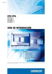
Cat. No. I560-E2-04<strong>RX</strong>Customised to your machineModel: 3G3<strong>RX</strong>200 V Class Three-Phase Input 0.4 to 55 kW400 V Class Three-Phase Input 0.4 to 132 kWUSER’S <strong>MANUAL</strong>
IntroductionIntroductionThank you for choosing the general-purpose Inverter <strong>RX</strong> Series. This User's Manual (hereinaftercalled "this manual") describes the parameter setting methods required for installation/wiring andoperation of the <strong>RX</strong> model, as well as troubleshooting and inspection methods.• This manual should be delivered to the actual end user of the product.• After reading this manual, keep it handy for future reference.• This manual describes the specifications and functions of the product as well as the relationsbetween them. You should assume that anything not described in this manual is not possible withthe product.• Intended readersThis manual is intended for:Those with knowledge of the workings of electricity (qualified electric engineers or the equivalent),and also in charge of:• Introducing the control equipment• Designing the control system• Installing and/or connecting the control equipment• Field management1
Read and Understand this ManualRead and Understand this ManualPlease read and understand this manual before using the product. Please consult your OMRON representativeif you have any questions or comments.Warranty and Limitations of LiabilityWARRANTYOMRON's exclusive warranty is that the products are free from defects in materials and workmanship for aperiod of one year (or other period if specified) from date of sale by OMRON.OMRON MAKES NO WARRANTY OR REPRESENTATION, EXPRESS OR IMPLIED, REGARDINGNON-INFRINGEMENT, MERCHANTABILITY, OR FITNESS FOR PARTICULAR PURPOSE OF THEPRODUCTS. ANY BUYER OR USER ACKNOWLEDGES THAT THE BUYER OR USER ALONE HASDETERMINED THAT THE PRODUCTS WILL SUITABLY MEET THE REQUIREMENTS OF THEIRINTENDED USE. OMRON DISCLAIMS ALL OTHER WARRANTIES, EXPRESS OR IMPLIED.LIMITATIONS OF LIABILITYOMRON SHALL NOT BE RESPONSIBLE FOR SPECIAL, INDIRECT, OR CONSEQUENTIALDAMAGES, LOSS OF PROFITS OR COMMERCIAL LOSS IN ANY WAY CONNECTED WITH THEPRODUCTS, WHETHER SUCH CLAIM IS BASED ON CONTRACT, WARRANTY, NEGLIGENCE, ORSTRICT LIABILITY.In no event shall the responsibility of OMRON for any act exceed the individual price of the product onwhich liability is asserted.IN NO EVENT SHALL OMRON BE RESPONSIBLE FOR WARRANTY, REPAIR, OR OTHER CLAIMSREGARDING THE PRODUCTS UNLESS OMRON'S ANALYSIS CONFIRMS THAT THE PRODUCTSWERE PROPERLY HANDLED, STORED, INSTALLED, AND MAINTAINED AND NOT SUBJECT TOCONTAMINATION, ABUSE, MISUSE, OR INAPPROPRIATE MODIFICATION OR REPAIR.2
Read and Understand this ManualApplication ConsiderationsSUITABILITY FOR USEOMRON shall not be responsible for conformity with any standards, codes, or regulations that apply tothe combination of products in the customer's application or use of the products.At the customer's request, OMRON will provide applicable third party certification documents identifyingratings and limitations of use that apply to the products. This information by itself is not sufficient for acomplete determination of the suitability of the products in combination with the end product, machine,system, or other application or use.The following are some examples of applications for which particular attention must be given. This is notintended to be an exhaustive list of all possible uses of the products, nor is it intended to imply that theuses listed may be suitable for the products:• Outdoor use, uses involving potential chemical contamination or electrical interference, or conditionsor uses not described in this manual.• Nuclear energy control systems, combustion systems, railroad systems, aviation systems, medicalequipment, amusement machines, vehicles, safety equipment, and installations subject to separateindustry or government regulations.• Systems, machines, and equipment that could present a risk to life or property.Please know and observe all prohibitions of use applicable to the products.NEVER USE THE PRODUCTS FOR AN APPLICATION INVOLVING SERIOUS RISK TO LIFE ORPROPERTY WITHOUT ENSURING THAT THE SYSTEM AS A WHOLE HAS BEEN DESIGNED TOADDRESS THE RISKS, AND THAT THE OMRON PRODUCTS ARE PROPERLY RATED ANDINSTALLED FOR THE INTENDED USE WITHIN THE OVERALL EQUIPMENT OR SYSTEM.PROGRAMMABLE PRODUCTSOMRON shall not be responsible for the user's programming of a programmable product, or anyconsequence thereof.3
Safety PrecautionsCAUTIONDo not connect resistors to the terminals (PD/+1, P/+, N/-) directly. Doing so might result in a smallscalefire, heat generation or damage to the unit.Install a stop motion device to ensure safety. Not doing so might result in a minor injury. (A holdingbrake is not a stop motion device designed to ensure safety.)Be sure to use a specified type of braking resistor/regenerative braking unit. In case of a brakingresistor, install a thermal relay that monitors the temperature of the resistor. Not doing so mightresult in a moderate burn due to the heat generated in the braking resistor/regenerative brakingunit. Configure a sequence that enables the Inverter power to turn off when unusual overheating isdetected in the braking resistor/regenerative braking unit.The Inverter has high voltage parts inside which, if short-circuited, might cause damage to itself orother property. Place covers on the openings or take other precautions to make sure that no metalobjects such as cutting bits or lead wire scraps go inside when installing and wiring.Do not touch the Inverter fins, braking resistors and the motor, which become too hot during thepower supply and for some time after the power shutoff. Doing so may result in a burn.Take safety precautions such as setting up a molded-case circuit breaker (MCCB) that matchesthe Inverter capacity on the power supply side. Not doing so might result in damage to property dueto the short circuit of the load.Do not dismantle, repair or modify this product.Doing so may result in an injury.6
Precautions for Safe UsePrecautions for Safe Use•Installation and StorageDo not store or use the product in the following places.•Locations subject to direct sunlight.•Locations subject to ambient temperature exceeding the specifications.•Locations subject to relative humidity exceeding the specifications.•Locations subject to condensation due to severe temperature fluctuations.•Locations subject to corrosive or flammable gases.•Locations subject to exposure to combustibles.•Locations subject to dust (especially iron dust) or salts.•Locations subject to exposure to water, oil, or chemicals.•Locations subject to shock or vibration.•Transporting, Installation, and Wiring•Do not drop or apply strong impact on the product. Doing so may result in damaged parts or malfunction.•Do not hold by the front cover and terminal block cover, but hold by the fins during transportation.•Do not connect an AC power supply voltage to the control input/output terminals. Doing so may result indamage to the product.•Be sure to tighten the screws on the terminal block securely.Wiring work must be done after installing the unit body.•Do not connect any load other than a three-phase inductive motor to the U, V, and W output terminals.•Take sufficient shielding measures when using the product in the following locations. Not doing so mayresult in damage to the product.Locations subject to static electricity or other forms of noise.Locations subject to strong magnetic fields.Locations close to power lines.•Operation and Adjustment•Be sure to confirm the permissible range of motors and machines before operation because the Inverterspeed can be changed easily from low to high.•Provide a separate holding brake if necessary.•Maintenance and Inspection•Be sure to confirm safety before conducting maintenance, inspection or parts replacement.7
Precautions for Correct UsePrecautions for Correct Use•Installation•Mount the product vertically on a wall with the product's longer sides upright.The material of the wall has to be noninflammable such as a metal plate.•Main Circuit Power Supply•Confirm that the rated input voltage of the Inverter is the same as AC power supply voltage.•Error Retry Function•Do not come close to the machine when using the error retry function because the machine may abruptlystart when stopped by an alarm.•Be sure to confirm the RUN signal is turned off before resetting the alarm because the machine mayabruptly start.•Non-Stop Function at Momentary Power Interruption•Do not come close to the machine when selecting restart in the non-stop function at momentary powerinterruption selection (b050) because the machine may abruptly start after the power is turned on.•Operation Stop Command•Provide a separate emergency stop switch because the STOP key on the Digital Operator is valid only whenfunction settings are performed.•When checking a signal during the power supply and the voltage is erroneously applied to the control inputterminals, the motor may start abruptly. Be sure to confirm safety before checking a signal.•Product Disposal•Comply with the local ordinance and regulations when disposing of the product.8
Precautions for Correct UseWarning LabelsWarning labels are located on the Inverter as shown in the following illustration.Be sure to follow the instructions.HITACHIWARNINGLOCALREMOTEREADWRITEESCFWDREVWarning Description9
Checking Before UnpackingChecking Before Unpacking•Checking the ProductOn delivery, be sure to check that the delivered product is the Inverter <strong>RX</strong> model that you ordered.Should you find any problems with the product, immediately contact your nearest local salesrepresentative or OMRON sales office.•Checking the Nameplate•Checking the Model3G3<strong>RX</strong>-A2055-EFF: Built-in filterE: Europe standardMax. applicable motor capacity0040070150220370400550751101500.4 kW0.75 kW1.5 kW2.2 kW3.7 kW4.0 kW5.5 kW7.5 kW11 kW15 kWVoltage class243-phase 200 V AC (200-V class)3-phase 400 V AC (400-V class)Enclosure ratingAB185 18.5 kW220 22 kW300 30 kW370 37 kW450 45 kW550 55 kW750 75 kW900 90 kW11K 110 kW13K 132 kWPanel-mounting (IP20 min.) or closedwall-mounting modelsIP00•Checking the AccessoriesNote that this manual is the only accessory included with the <strong>RX</strong> model.Mounting screws and other necessary parts must be provided by the user.10
Revision HistoryRevision History•A manual revision code appears as a suffix to the catalog number located at thelower left of the front and back covers.Cat. No. I560-E2-04Revision codeRevision code Revision date Description01 April 2009 First version04 February 2012 Major changes11
About This ManualAbout This ManualThis User's Manual is compiled chapter by chapter for user's convenience as follows.Understanding the following configuration ensures more effective use of the product.OverviewChapter 1 Overview Describes features and names of parts.Chapter 2DesignProvides external dimensions, installation dimensions, peripheral devicedesign/selection instructions, and other information necessary fordesign.Chapter 3OperationDescribes names of parts, the Inverter's operations, including how to usethe keys on the Digital Operator, and the monitor function.Chapter 4 Functions Describes the functions of the Inverter.Chapter 5Chapter 6Chapter 7AppendixMaintenanceOperationsInspection andMaintenanceSpecificationsDescribes the causes and their countermeasures if the Inverter fails,including the solutions to possible troubles (troubleshooting).Describes items for periodical inspection and/or maintenance for theInverter.Provides Inverter specifications, as well as the specifications anddimensions of peripheral devices.Describes the summarized parameter settings as a reference for userswho have used this Inverter and understood the functions.12
ContentsIntroduction..............................................................................................1Read and Understand this Manual ..........................................................2Safety Precautions ..................................................................................5Precautions for Safe Use.........................................................................7Precautions for Correct Use ....................................................................8Checking Before Unpacking ....................................................................10Revision History.......................................................................................11About This Manual...................................................................................12Chapter 1 Overview1-1 Functions .................................................................................................1-11-2 Appearance and Names of Parts.............................................................1-4Chapter 2 Design2-1 Installation................................................................................................2-12-2 Wiring.......................................................................................................2-5Chapter 3 Operation3-1 Operation Method ....................................................................................3-33-2 LCD Display.............................................................................................3-43-3 Test Run Procedure.................................................................................3-53-4 Operation .................................................................................................3-63-5 Read/Write function and operation ..........................................................3-133-6 Test Run Operation .................................................................................3-143-7 Part Names and Descriptions of the Digital Operator..............................3-173-8 Parameter Transition ...............................................................................3-193-9 Parameter List .........................................................................................3-21Chapter 4 Functions4-1 Monitor Mode...........................................................................................4-14-2 Function Mode .........................................................................................4-84-3 Functions When PG Option Board (3G3AX-PG01) Is Used....................4-1234-4 Communication Function ........................................................................4-145Chapter 5 Maintenance Operations5-1 Protective Functions and Troubleshooting ..............................................5-15-2 Warning Function.....................................................................................5-10Chapter 6 Inspection and Maintenance6-1 Inspection and Maintenance....................................................................6-113
ContentsChapter 7 Specifications7-1 Standard Specification List...................................................................... 7-17-2 Dimensional Drawing .............................................................................. 7-77-3 Options.................................................................................................... 7-15Chapter App AppendixAppendix-1Parameter List ................................................................................. App-1Appendix-2Product Life Curve........................................................................... App-47Appendix-3Life Alarm Output............................................................................. App-48Appendix-4EC Declaration of Conformity .......................................................... App-49Index..................................................................................................... Index-114
Chapter 1Overview1-1 Functions .......................................................... 1-11-2 Appearance and Names of Parts .................... 1-4
1-1 Functions11Overview1-1 FunctionsOverview<strong>RX</strong> Inverter ModelsRated voltage Enclosure rating Max. applicable motor capacity Model0.4 kW 3G3<strong>RX</strong>-A20040.75 kW 3G3<strong>RX</strong>-A20071.5 kW 3G3<strong>RX</strong>-A20152.2 kW 3G3<strong>RX</strong>-A20223.7 kW 3G3<strong>RX</strong>-A20375.5 kW 3G3<strong>RX</strong>-A20557.5 kW 3G3<strong>RX</strong>-A20753-phase 200 V AC11 kW 3G3<strong>RX</strong>-A211015 kW 3G3<strong>RX</strong>-A215018.5 kW 3G3<strong>RX</strong>-A218522 kW 3G3<strong>RX</strong>-A222030 kW 3G3<strong>RX</strong>-A230037 kW 3G3<strong>RX</strong>-A237045 kW 3G3<strong>RX</strong>-A2450IP2055 kW 3G3<strong>RX</strong>-A25500.4 kW 3G3<strong>RX</strong>-A40040.75 kW 3G3<strong>RX</strong>-A40071.5 kW 3G3<strong>RX</strong>-A40152.2 kW 3G3<strong>RX</strong>-A40224.0 kW 3G3<strong>RX</strong>-A40405.5 kW 3G3<strong>RX</strong>-A40557.5 kW 3G3<strong>RX</strong>-A407511 kW 3G3<strong>RX</strong>-A411015 kW 3G3<strong>RX</strong>-A41503-phase 400 V AC18.5 kW 3G3<strong>RX</strong>-A418522 kW 3G3<strong>RX</strong>-A422030 kW 3G3<strong>RX</strong>-A430037 kW 3G3<strong>RX</strong>-A437045 kW 3G3<strong>RX</strong>-A445055 kW 3G3<strong>RX</strong>-A455075 kW 3G3<strong>RX</strong>-B475090 kW 3G3<strong>RX</strong>-B4900IP00110 kW 3G3<strong>RX</strong>-B411K132 kW 3G3<strong>RX</strong>-B413K1-1
1-1 FunctionsInternational Standards Models (EC Directives and UL/cUL Standards)The <strong>RX</strong> Inverter meets the EC Directives and UL/cUL standard requirements for worldwide use.ClassificationEC Directives EMC Directive EN61800-3: 2004UL/cUL StandardsApplicable standardLow-voltage Directive EN61800-5-1: 2007UL508C1OverviewHuman Environment-friendly, High-performance, General-purposeInverters Suitable for Various Advanced Applications•High PerformanceHigh Starting TorqueWith the vector control and auto-tuning functions, the <strong>RX</strong> Series has achieved high starting torquein excess of 200% at 0.3 Hz.Trip SuppressionThis Inverter features two trip suppression functions: "Overcurrent trip suppression function" tosuppress overcurrent trip during acceleration, and "Overvoltage suppression function duringdeceleration" to suppress overvoltage trip during deceleration. Therefore, the <strong>RX</strong> Series providestough operational capabilities regardless of the severe time setting of acceleration and deceleration.•Various ApplicationsSensor-less Vector Control at 0 HzThe <strong>RX</strong> Series provides sensor-less vector control, which is useful for up/down applications. It canprovide a high torque of 150%, even at a speed reference of 0 Hz (150% torque is available whenthe Inverter capacity is increased by one rank). This function contributes to simplification of controlprograms and extension of the service life of the brake.Emergency Shutoff FunctionBy switching the dedicated switch (SW1) this function enables you to change the multi-functioninput (input 3) to the emergency shutoff input. You can directly turn off a motor control power modulewithout operating the software. This function simplifies construction of safety applications.Built-in Braking Circuit (up to 22 kW)The Inverter models with 22 kW or lower capacity incorporate a braking transistor, enabling spacesavingconfiguration for applications that need rapid acceleration and stop.Restart Speed Search FunctionFor a free-running motor (e.g. a fan motor), this function checks the direction of rotation andfrequency, enabling smooth restart of the motor.High-torque Multi-operationThe <strong>RX</strong> Series enables balanced torque control for the whole system, in proportion to multiple motorloads.Deceleration Stop During Power FailureDuring a power failure or momentary power interruption, the <strong>RX</strong> Series can decelerate and stop amotor by using the motor braking energy.1-2
1-1 Functions1•Human Environment-friendly FeaturesMore Simplified Parameter Settings and View•Only parameters that have been changed from the default settings can be viewed.•With the user setting function, only 12 parameters for frequent use can be viewed.OverviewCompliance With Safety StandardsThe <strong>RX</strong> Series meets the requirements of the CE and UL/cUL and complies with various standards.The RoHS DirectiveThe standard model meets the requirements of the RoHS Directive.Easily Meets the Requirements Specified by the Ministry of Land, Infrastructure andTransport of JapanThe <strong>RX</strong> Series incorporates a zero-phase reactor (radio noise filter) as a standard specification.When an optional DC reactor is added, the <strong>RX</strong> Series meets the requirements specified by the Ministryof Land, Infrastructure and Transport of Japan.1-3
1-2 Appearance and Names of Parts1-2 Appearance and Names of Parts1When the product is unpacked, it appears as below. (Example of 3G3<strong>RX</strong>-A2150/A4150 to A2220/A4220)Front coverHITACHIWARNINGOverviewDigital OperatorLOCALREMOTEREADWRITEESCFWDREVTerminal block coverOpen the terminal block cover and you can connect cables to the main circuit terminal block, as wellas the control circuit terminal block.Also, open the front cover and you can mount the optional board.Position for installingoptional board 1Position for installingoptional board 2Control circuit terminal blockMain circuit terminal blockBacking plate1-4
Chapter 2Design2-1 Installation ........................................................ 2-12-2 Wiring ................................................................ 2-5
2-1 Installation2Design2-1 Installation2DANGERDesignTurn off the power supply and implement wiring correctly. Not doing so may result in a serious injurydue to an electric shock.Wiring work must be carried out only by qualified personnel. Not doing so may result in a seriousinjury due to an electric shock.Do not change wiring and slide switches (SW1), put on or take off Digital Operator and optionaldevices, replace cooling fans while the input power is being supplied. Doing so may result in aserious injury due to an electric shock.Be sure to ground the unit. Not doing so may result in a serious injury due to an electric shock or fire.(200-V class: type-D grounding, 400-V class: type-C grounding)CAUTIONDo not connect resistors to the terminals (PD/+1, P/+, N/-) directly. Doing so might result in a smallscalefire, heat generation or damage to the unit.Install a stop motion device to ensure safety. Not doing so might result in a minor injury. (A holdingbrake is not a stop motion device designed to ensure safety.)Be sure to use a specified type of braking resistor/regenerative braking unit. In case of a brakingresistor, install a thermal relay that monitors the temperature of the resistor. Not doing so might resultin a moderate burn due to the heat generated in the braking resistor/regenerative braking unit.Configure a sequence that enables the Inverter power to turn off when unusual overheating isdetected in the braking resistor/regenerative braking unit.The Inverter has high voltage parts inside which, if short-circuited, might cause damage to itself orother property. Place covers on the openings or take other precautions to make sure that no metalobjects such as cutting bits or lead wire scraps go inside when installing and wiring.2-1
LOCALREMOTEESCFWDHITACHIREADREVWARNINGWRITEESCLOCALREMOTEHITACHIWARNINGESC2-1 InstallationSafety Information•Installation and StorageDo not store or use the product in the following places.•Locations subject to direct sunlight.•Locations subject to ambient temperature exceeding the specifications.•Locations subject to relative humidity exceeding the specifications.•Locations subject to condensation due to severe temperature fluctuations.•Locations subject to corrosive or flammable gases.•Locations subject to exposure to combustibles.•Locations subject to dust (especially iron dust) or salts.•Locations subject to exposure to water, oil, or chemicals.•Locations subject to shock or vibration.2Design•Transporting, Installation, and Wiring•Do not drop or apply strong impact on the product. Doing so may result in damaged parts or malfunction.•Do not hold by the front cover and terminal block cover, but hold by the fins during transportation.•Do not connect an AC power supply voltage to the control input/output terminals. Doing so may result indamage to the product.•Be sure to tighten the screws on the terminal block securely.Wiring work must be done after installing the unit body.•Do not connect any load other than a three-phase inductive motor to the U, V, and W output terminals.•Take sufficient shielding measures when using the product in the following locations. Not doing so mayresult in damage to the product.Locations subject to static electricity or other forms of noise.Locations subject to strong magnetic fields.Locations close to power lines.Precautions for Use•Installation•Install the Inverter vertically on the wall.Install the Inverter on a nonflammable wall surface material, like metal.READ WRITEFWD REVHITACHILOCALREMOTEWARNINGFWD REVREAD WRITEPosition forinstalling a screw•Main Circuit Power Supply•Confirm that the rated input voltage of the Inverter matches the AC power supply voltage.2-2
2-1 Installation2•Installation Environment•Increased ambient temperatures will shorten the life of the Inverter.•Keep the Inverter away from heating elements (such as a braking resistor, DC reactor, etc.).If the Inverter is installed in an enclosure, keep the ambient temperature within the range of thespecifications, taking dimensions and ventilation into consideration.Design*1Inverter5 cm min. 5 cm min.AirflowInverterWallSave enough space to prevent the upperand lower wiring ducts from blockingcooling airflow.*1 10 cm min.*2 10 cm min.Note that replacing the smoothing capacitorrequires 22 cm or more.*2•When several <strong>RX</strong> models are installed in an enclosure and a ventilation fan is mounted in theenclosure, be careful about the layout of the Inverters and the air intake apertures.Depending on the internal layout of the panel, the Inverter's cooling effect may deteriorate,resulting in an increase in ambient temperature.Also, use thorough caution in making sure that the Inverter's ambient temperature is within theallowable operating temperature range.Ventilation fanVentilation fanInverterInverter(Correct example)(Incorrect example)•Before installing the Inverter, place a cover over all the ventilation openings to shield them fromforeign objects.After completing the installation process, be sure to remove the covers from the Inverter beforeoperation.•Below is the heat radiation according to the Inverter capacity.Inverter capacity (kw) 0.4 0.75 1.5 2.2 3.7 5.5 7.5 11 15 18.5Load with 70% loss (W) 64 76 102 127 179 242 312 435 575 698Load with 100% loss (W) 70 88 125 160 235 325 425 600 800 975Efficiency at rated output (%) 85.1 89.5 92.3 93.2 94.0 94.4 94.6 94.8 94.9 95.0Inverter capacity (kw) 22 30 37 45 55 75 90 110 132Load with 70% loss (W) 820 1100 1345 1625 1975 2675 3375 3900 4670Load with 100% loss (W) 1150 1550 1900 2300 2800 3800 4800 5550 6650Efficiency at rated output (%) 95.0 95.0 95.1 95.1 95.1 95.2 95.2 95.2 95.2•To raise the carrier frequency, reduce the output current (or derate the rated current).2-3
2-1 InstallationBacking Plate• Inverter with 22 kW or Lower CapacityWhen running cables, cut the points between the backing plate and unnecessary portions withnippers or a wire cutter, and remove.2Connecting points• Inverter with 30 kW or Higher CapacityUnnecessary portionDesignFor Connection Without Cable ConduitMake a cut in the rubber bushing of the backing plate with nippers or a wire cutter, and insert a cable.Backing plateRubber bushingFor Connection With Cable ConduitRemove the rubber bushing from the conduit connecting portions, and connect the cable conduit.* Do not remove the rubber bushing unless you connect a cable conduit.Otherwise, the cable sheath may be damaged by the inner edge of the backing plate, resulting inshort-circuit or ground fault.2-4
2-2 Wiring2-2 Wiring2Standard Connection DiagramDC reactor(optional)Braking resistor(optional)Design3-phase 200 V AC3-phase 400 V ACFrequency setting unit500 to 2 kWShort-circuitwireTo wire the control circuit powersupply and main circuit powersupply separately, be sure toremove the J51 connectorwire first.Multi-function input 1Multi-function input 2Multi-function input 3Multi-function input 4Multi-function input 5Multi-function input 6Multi-function input 7Multi-function input 8Sequence input commonThermistorJ51Control circuitpower supplyFrequency reference power supplyFrequency reference input (voltage)Frequency reference auxiliary input (voltage)Frequency reference input (current)Frequency reference commonPD/+1R/L1S/L2T/L3RTRoToCM1PLCFW12345678P24CM1THHOO2OIL *1100W10kWP/+10kWN/-DC24VDC10VRBU/T1V/T2W/T3AL1AL2AL012 Multi-function output 213 Multi-function output 314 Multi-function output 415 Multi-function output 5CM2SPSNRPSNAMAMIFMOption 1Option 1Relay output *1Common11 Multi-function output 1MMulti-function output commonRS485 communicationFor terminationresistorsAnalog monitor output(voltage output)Analog monitor output(current output)Digital monitor output(PWM output)*1L is the common reference for analog input and also for analog output.2-5
2-2 Wiring• Main Circuit TerminalsTerminal symbol Terminal name DescriptionR/L1, S/L2,T/L3U/T1,V/T2,W/T3PD/+1, P/+P/+, RBP/+, N/-Main power supply inputterminalInverter output terminalExternal DC reactorterminalBraking resistorconnection terminalsRegenerative brakingunit connection terminalConnect the input power supply.Connect to the 3-phase motor.Remove the short-circuit bar between terminals "PD/+1"and "P/+", and connect the optional power factorimprovement DC reactor.Connect optional external braking resistors. (The RBterminal is provided for the Inverters with 22 kW or lowercapacity.)Connect optional regenerative braking units.G Ground terminal Inverter case ground terminal. Connect this terminal to theground.type-D (200-V class), type-C (400-V class)2Design• Control Circuit TerminalTerminalsymbolTerminal name Description SpecificationsHFrequency referencepower supply output+10 V DC power supply for the O terminal. Allowable load current:20 mA max.OFrequency referenceinput(Voltage)With a 0 to 10 V DC voltage input, thefrequency reaches the maximum at 10 V.Set at A014 if the maximum frequencyneeds to be achieved at lower than 10 V.Input impedance 10 kAllowable input voltagerange:-0.3 to +12 V DCAnalogFrequency reference inputO2OIAuxiliary frequencyreference input(Voltage)Frequency referenceinput(Current)With a 0 to ±10 V DC voltage input, the O2signal is added to the frequency referencesignal of the O or OI terminal. By changingthe setting, the frequency reference can beinput even with the O2 terminalindependently.With a 4 to 20 mA DC current input, themaximum frequency is set at 20 mA. The OIsignal is only active when the AT terminal isON. Allocate the AT function to the multifunctioninput terminal.Input impedance 10 kAllowable input voltagerange:0 to ±12 V DCInput impedance 100 Allowable max. current:24 mALFrequency referencecommonCommon terminal for the frequency settingsignals (O, O2 and OI) and the analog outputterminals (AM and AMI). Do not connect thisterminal to the ground.Continued to the next page2-6
2-2 WiringTerminalsymbolTerminal name Description Specifications2DesignAnalogMonitor outputAMAMIMulti-function analogoutput(Voltage)Multi-function analogoutput(Current)This terminal outputs a signal selected fromthe "0 to 10 V DC Voltage Output" monitoritems: Output frequency, Output current,Output torque (with/without sign), Outputvoltage, Input power, Electronic thermal loadrate, LAD frequency, Motor temperature,and Fin temperature.This terminal outputs a signal selected fromthe "4 to 20 mA DC Current Output" monitoritems: Output frequency, Output current,Output torque (without sign), Output voltage,Input power, Electronic thermal load rate,LAD frequency, Motor temperature, and Fintemperature.Allowable max. current:2 mAAllowable loadimpedance:250 max.Digital (contact)Monitor outputPower supplyFMMulti-function digitaloutputThis terminal outputs a signal selected fromthe "0 to 10 V DC Voltage Output (PWM)"monitor items: Output frequency, Outputcurrent, Output torque (without sign), Outputvoltage, Input power, Electronic thermal loadrate, LAD frequency, Motor temperature, Fintemperature, Digital output frequency, andDigital current monitor."Digital output frequency", and "Digitalcurrent monitor" output a digital pulse at 0/10V DC pulse voltage and 50% duty ratio.P24 Internal 24 V DC 24 V DC power supply for contact inputsignal.When the source logic is selected, thisterminal functions as the contact inputcommon terminal.CM1 Input common Common terminal for the interface powersupply P24 terminal, thermistor input THterminal and digital monitor FM terminal.When the sink logic is selected, this terminalfunctions as the contact input commonterminal. Do not connect this terminal to theground.Allowable max. current:1.2 mAMax. frequency:3.6 kHzAllowable max. outputcurrent:100 mAContinued to the next page2-7
2-2 WiringTerminalsymbolTerminal name Description SpecificationsRUN commandFWForward rotationcommand terminalWhen the FW signal is ON, the motor runsforward. When it is OFF, the motor deceleratesand stops.[Contact input ONcondition]Voltage betweeneach input terminaland the PLC terminal:18 V DC or more2Digital (contact)Contact inputFunction / Selection12345678PLCMulti-function inputMulti-function inputcommonSelect 8 functions from among the 61 functionsand allocate them to terminals 1 to 8.Note: Only terminals 1 and 3 can be used for theemergency shutoff function. For details,refer to "Emergency Shutoff Function"(page 2-9).The sink and source logic for contact input canbe switched by connecting a short-circuit bar onthe control terminal block.Short-circuiting P24 and PLC Sink logic,Short-circuiting PLC and CM1 Source logicTo activate contact input via an external powersupply, remove the short-circuit bar andconnect PLC terminal to the external interfacecircuit.Input impedancebetween each inputterminal and the PLCterminal: 4.7 kAllowable max.voltage:Voltage betweeneach input terminaland the PLC terminal:27 V DCLoad current at 27 VDC power supplyvoltage:Approx. 5.6 mADesignOpen collector outputStatus / Factor1112131415CM2Multi-function outputMulti-function outputcommonSelect 5 functions from among 45, and allocatethem to terminals 11 through 15.If an alarm code is selected in C062, terminals11 to 13, or terminals 11 to 14 always output analarm factor code (e.g. Inverter trip). The signalbetween each terminal and CM2 alwayscorresponds to the sink or source logic.Common terminals for multi-function outputterminals 11 to 15.Between eachterminal and CM2Voltage drop 4 Vmax. at power-onMax. allowablevoltage: 27 V DCMax. allowablecurrent: 50 mADigital (contact)Relay outputStatus, alarm, etc.AL2AL1AL0Relay output Select the desired functions from among 45functions, and allocate them. SPDT contactoutput.By factory default, the relay output (AL2, AL1)contact selection (C036) is set at NC contactRelay outputcommonbetween AL2-AL0, and NO contact betweenAL1-AL0.Contact max.capacityAL2-AL0250 V AC, 2 A(Resistance)0.2 A (Induction)AL1-AL0250 V AC, 1 A(Resistance)0.2 A (Induction)Contact min. capacity100 V AC, 10 mA5 V DC, 100 mAContinued to the next page2-8
2-2 WiringTerminalsymbolTerminal name Description Specifications2DesignAnalogAnalog inputSensorTHExternal thermistorinput Terminal•Slide Switch (SW1) SettingsConnect an external thermistor to this terminal,to trip the Inverter when a temperature erroroccurs.The CM1 terminal functions as the commonterminal.[Recommended thermistor characteristics]Allowable rated power: 100 mW min.Impedance at temperature error: 3 kTemperature error detection level is adjustablebetween 0 and 9999 .Allowable inputvoltage range0 to 8 V DC[Input circuit]THThermistorCM1The built-in slide switch is used to enable or disable the emergency shutoff function. (FactoryDefault: Disabled)* For the location of the slide switch, refer to (page 2-11).8 V DC10 k1 kEmergency Shutoff Function (Factory Default: Disabled)•This function is intended to turn off the Inverter output (stop switching the main element) via onlythe multi-function input terminal of the hardware circuit without going through the CPU software.* This function stops switching of the main element.The circuit is not electrically turned off. While thepower supply is ON, do not touch the Inverter terminals and power cable (e.g. motor cable). Doingso may result in electric shock, injury or ground fault.•When this function is enabled, the multi-function input terminals 1 and 3 are exclusively used forthis function. No other function can be allocated to these terminals. If another function has beenallocated, it will automatically be disabled, and terminals 1 and 3 are changed to the emergencyshutoff terminals.Function of multi-function input terminal 1Reset signal (RS) / NO contact (Fixed)This signal is used to reset the Inverter, and to reset the emergency shutoff trip [ E37.* ].Function of multi-function input terminal 3Emergency shutoff signal (EMR) / NC contact (Fixed)This signal is used to turn off the Inverter output without using the built-in CPU.With this signal input, the Inverter activates an emergency shutoff trip [ E37. * ].* If multi-function input terminal 3 has not been connected or disconnected, or if the signal logic isnot matched, the Inverter activates an emergency shutoff trip [E37. *]. After checking the cableconnection and the signal logic, input the reset signal (RS).Emergency shutoff trip [ E37. * ] can be reset only by the reset signal (RS) via multi-function inputterminal 1. (It cannot be reset with the Digital Operator.)•To enable this function, set the slide switch SW1 lever in the Inverter to [ON].(With the factory default setting, slide switch SW1 is [OFF]. [This function is disabled.])2-9
2-2 WiringSlide switch(SW1)settingSW1 OFFEmergencyshutoff:Disabled(factorydefault)SW1 ONEmergencyshutoff:Enabled*5Turning SW1on, and thenoffEmergencyshutoff:Disabled*3 *5* Before operating slide switch SW1, make sure that the input power supply is OFF.Slide switch SW1 setting and status of multi-function input terminals 1 and 3Multi-function input terminal 1 Multi-function input terminal 3Multi-function input 1selection[ C001 ][Can be selectedrandomly] *4FactorydefaultFixedfunction(Cannotbechanged)[Can be selectedrandomly] *4Holdssettingwhile SW1is ON.01 (RV) FactorydefaultMulti-function input 3Multi-function input 1[ C011 ] *1 [ C003 ]operation selectionselection[Can be selectedrandomly] *400 (NO) Factorydefault[Can be selectedrandomly] *412 (EXT) FactorydefaultAutomatic allocation to multi-function input terminals 1 and 3,and the input terminal with 18 (RS) setting *318 (RS) Fixedfunction(Cannotbechanged)18 (RS) Holdssettingwhile SW1is ON.[Can be selectedrandomly] *400 (NO) Fixedfunction(Cannotbechanged)00 (NO) Emergencyshutofffunction:Reset[Can be selectedrandomly] *464 (EMR) Fixedfunction(Cannotbechanged)no(noallocation)Multi-function input 3operation selection[ C013 ]*1 *2[Can be selectedrandomly] *400 (NO)01 (NC)[Can be selectedrandomly] *4Holdssettingwhile SW1is ON.01 (NC)2Design*1. With the terminal with input terminal selection [18 (RS)], NO/NC selection is fixed to [00 (NO)].*2. When [C003] is [64 (EMR)], [C013] is fixed to [01 (NC)].*3. If [18 (RS)] has been allocated to a multi-function input terminal (except for 3) other than terminal1 before switch SW1 is set to "ON", the input terminal selection for the relevant terminal will beautomatically changed to "no (no allocation)" by setting SW1 to "ON". This is done in order toprevent duplicated allocation of this function. Then, even if SW1 is reset to [OFF], the initialallocation cannot be restored. The User should Re-allocate the terminal function.Example) When the multi-function input terminal 2 [C002] is [18 (RS)], setting SW1 to [ON] changesthe [C002] setting to [no (no allocation)]. [18 (RS)] will be allocated to the multi-functioninput terminal 1 [C001].Then, even if SW1 is reset to [OFF], the multi-function input terminal 2 [C002] setting is [no (noallocation)], and the multi-function input terminal 1 [C001] setting is [18 (RS)].*4. Input terminal selection [64 (EMR)] cannot be selected with the Digital Operator. When slideswitch SW1 is set to [ON], this function will be automatically allocated.2-10
2-2 Wiring*5. Once slide switch SW1 is set to [ON], allocation of multi-function input terminals 1 and 3 will notbe restored, even if SW1 is reset to [OFF] afterward. Re-allocate the terminal function.2DesignSlide switch SW1ONSlide lever (factory default: OFF)OFFONWiring the Main Circuit Terminals•Main Power Supply Input Terminals (R/L1, S/L2, T/L3)• Use an earth leakage breaker for circuit (wiring) protection between the power supply and themain power supply terminals (R/L1, S/L2, T/L3).• An earth leakage breaker may malfunction due to the effect of high frequency. Use an earthleakage breaker with a large high-frequency sensitivity current rating.• If the Inverter protection function is activated, a malfunction or accident may have occurred to yoursystem. Connect a magnetic contactor to turn off the Inverter power supply.• Do not start or stop the Inverter by switching ON/OFF the magnetic contactor connected on theInverter power supply input (primary) side and output (secondary) side.To start or stop the Inverter via an external signal, use the operation command (FW or RV) on thecontrol circuit terminal block.• This Inverter uses a 3-phase power supply. A single-phase power supply cannot be used.• Do not use this Inverter with a phase loss power input. Doing so may damage the Inverter.By factory default, the phase loss input protection is disabled. If a phase of power supply input isinterrupted, the Inverter reverts to the following status:R/L1-phase or T/L3-phase is interrupted:S/L2-phase is interrupted:The Inverter does not operate.The Inverter reverts to single-phase operation, causing atrip (due to undervoltage, overcurrent, etc.) or damage tothe Inverter.Even if the power input is under a phase loss condition, the internal capacitor is charged withvoltage, causing an electric shock or injury.When changing the cable connections, refer to the instructions on page 2-1.2-11
2-2 Wiring• In the following cases, the internal converter module may be damaged. Use caution to avoidthem:Imbalance of power supply voltage is 3% or more.Power supply capacity is ten times or more than the Inverter capacity, and also 500 kVA or more.Rapid change in power supply voltage.Example) When several Inverters are connected with a short bus.When the phase advance capacitor is turned on/off.2• Do not turn power on/off more than once every 3 minutes.Doing so may damage the Inverter.•Inverter Output Terminals (U/T1, V/T2, W/T3)• For connection of the output terminal, use the applicable cable or a cable with a larger diameter.Otherwise, the output voltage between the Inverter and the motor may drop.Particularly during low-frequency output, a voltage drop occurs with the cable, resulting in motortorque reduction.• Do not mount a phase advance capacitor or surge absorber. These devices cause the Inverter totrip, or may cause damage to the capacitor or surge absorber.• If the cable length exceeds 20 m (particularly, with 400-V class), a surge voltage may begenerated at the motor terminal due to stray capacitance or inductance of the cable, causing themotor to burn out.• To connect several motors, provide a thermal relay for each.• The RC value of each thermal relay should be 1.1 times of the motor rated current. The relay maytrip easily depending on the cable length. In this case, connect an AC reactor to the Inverteroutput.Design•DC Reactor Connection Terminal (PD/+1, P/+)• This terminal is used to connect the optional DC reactor for power factor improvement.By factory default, a short-circuit bar has been connected between the terminals PD/+1 and P/+.Before connecting the DC reactor, remove this short-circuit bar.• The length of the DC reactor connection cable should be 5 m or less.If the DC reactor is not used, do not remove the short-circuit bar.If you remove the short-circuit bar without connecting the DC reactor, no power is supplied tothe Inverter main circuit, disabling operation.•External Braking Resistor Connection Terminal (P/+, RB)/Regenerative BrakingUnit Connection Terminal (P/+, N/-)• The Inverters with 22 kW or lower capacity incorporate a regenerative braking circuit.To improve braking capability, mount the optional external braking resistor to this terminal.Do not mount a resistor whose resistance is lower than the specified value. Doing so may damagethe regenerative braking circuit.• The Inverters with 30 kW or higher capacity do not incorporate a regenerative braking circuit.To improve braking capability, the optional regenerative braking unit and braking resistor arerequired. In this case, connect the regenerative braking unit terminals (+, -) to the Inverterterminals (P/+, N/-).• The cable length should be 5 m or less. Twist the two wires.• Do not connect any device other than the optional regenerative braking unit or external brakingresistor to this terminal.2-12
2-2 Wiring2Design•Ground Terminal (G )• To prevent electric shock, be sure to ground the Inverter and the motor.• According to the Electric Apparatus Engineering Regulations, the 200-V class Inverter should beconnected to the grounding electrodes under type-D grounding conditions (conventional type 3grounding: ground resistance 100 or less), the 400-V class Inverter should be connected to thegrounding electrodes under type-C grounding conditions (conventional special type 3 grounding:ground resistance 10 or less).• For the ground cable, use the applicable cable or a cable with a larger diameter. Make the cablelength as short as possible.• When several Inverters are connected, the ground cable must not be connected across severalInverters, and must not be looped.Otherwise, the Inverters may malfunction.InverterInverterInverterInverterInverterInverterYour ground bolt•Installing Screws in the Main Circuit Terminal Block• For the main circuit terminal blocks of 3G3<strong>RX</strong>-A2055/-A2075/-A4055/-A4075, be sure to installthe terminal block screw washers with their grooved sides aligned vertically, as shown below.Not doing so may result in a contact failure or fire.(Intended terminals: R/L1, S/L2, T/L3, PD/+1, P/+, N/-, U/T1, V/T2, W/T3, RB)Terminal block screw washer2-13
2-2 Wiring• Arrangement of Main Circuit TerminalsThe terminal arrangement on the Inverter main circuit terminal block is shown below.Terminal arrangementApplicable modelRoToR/L1 S/L2 T/L3U/T1 V/T2 W/T32PD/+1 P/+ N/-RBGGCHARGE LED indicatorPD/+1 - P/+ short-circuit barWhen not using the DC reactor,keep the PD/+1 - P/+ short-circuit barattached.Design[EMC filter function switching method]Dummy plug(green)Filter enable pin(J61)Short plugIn order to enable the EMC filterfunction, set up the plug insertedinto the filter enable pin (J61) andfilter disable pin (J62) as shown inthe table below. Confirm thatelectrical power has beendisconnected before performing thissetup. Not doing so may result inelectric shock. Also, use with theplug inserted.3G3<strong>RX</strong>-A2004 to A20373G3<strong>RX</strong>-A4004 to A4037Ro,To: M4Ground terminal: M4Others: M4Filter disable pin (J62)EMC filter disabledEMC filter enabled (factory default)Filter enable pin (J61)Dummy plug (green)Short plugFilter disable pin (J62)Short plugDummy plug (green)CHARGE LED indicatorRBRoToR/L1 S/L2 T/L3 PD/+1 P/+ N/- U/T1 V/T2 W/T33G3<strong>RX</strong>-A2055, A20753G3<strong>RX</strong>-A4055, A4075GPD/+1 - P/+short-circuit barGRo,To: M4Ground terminal: M5Others: M5Ground terminal with short-circuitbar (shaded area) for EMC filterfunction switching[EMC filter function switching method]When not using the DCreactor, keep the PD/+1 - P/+short-circuit bar attached.3G3<strong>RX</strong>-A21103G3<strong>RX</strong>-A4110Ro,To: M4Ground terminal: M6Others: M5EMC filter enabled (factory default)EMC filter disabled2-14
2-2 WiringTerminal arrangementApplicable modelCHARGE LED indicatorRoToRB2R/L1 S/L2 T/L3 PD/+1 P/+ N/- U/T1 V/T2 W/T33G3<strong>RX</strong>-A2150 to A21853G3<strong>RX</strong>-A4150 to A4220DesignGGround terminal with short-circuitbar (shaded area) for EMC filterfunction switchingPD/+1 - P/+ short-circuitbarWhen not using the DCreactor, keep the PD/+1 - P/+short-circuit bar attached.GRo,To: M4Ground terminal: M6Others: M6[EMC filter function switching method]3G3<strong>RX</strong>-A2220Ro,To: M4Ground terminal: M6Others: M8EMC filter enabled (factory default)EMC filter disabledCHARGE LED indicatorRoTo3G3<strong>RX</strong>-A2300GR/L1 S/L2 T/L3 PD/+1 P/+ N/- U/T1 V/T2 W/T3GRo, To: M4Ground terminal: M6Others: M8Ground terminal with short-circuitbar (shaded area) for EMC filterfunction switching[EMC filter function switching method]PD/+1 - P/+ short-circuit barWhen not using the DC reactor,keep the PD/+1 - P/+short-circuit bar attached.3G3<strong>RX</strong>-A4300Ro,To: M4Ground terminal: M6Others: M63G3<strong>RX</strong>-A23703G3<strong>RX</strong>-A4370EMC filter enabled (factory default)EMC filter disabledRo,To: M4Ground terminal: M8Others: M82-15
2-2 WiringTerminal arrangementApplicable modelCHARGE LED indicatorRoToR/L1 S/L2 T/L3 PD/+1 P/+ N/- U/T1 V/T2 W/T3G2GPD/+1-P/+short-circuit barWhen not using the DCreactor, keep the PD/+1-P/+short-circuit bar attached.Ground terminal withshort-circuit bar (shaded area)for EMC filter function switchingG3G3<strong>RX</strong>-A24503G3<strong>RX</strong>-A44503G3<strong>RX</strong>-A4550Design[EMC filter function switching method]Ro,To: M4Ground terminal: M8Others: M8EMC filter enabled (factory default)EMC filter disabledCHARGE LED indicatorRoToGR/L1 S/L2 T/L3 PD/+1 P/+ N/- U/T1 V/T2 W/T3GPD/+1 - P/+short-circuit barWhen not using the DCreactor, keep the PD/+1 - P/+short-circuit bar attached.[EMC filter function switching method]Ground terminal withshort-circuit bar(shaded area) for EMCfilter function switchingG3G3<strong>RX</strong>-A2550Ro,To: M4Ground terminal: M8Others: M10EMC filter enabled (factory default)EMC filter disabled2-16
2-2 Wiring•Recommended Cable Size, Wiring Device and Crimp TerminalFor Inverter wiring, crimp terminal and terminal screw tightening torque, refer to the table below.2DesignMotoroutput(kW)ApplicableInverter modelPowercable(mm 2 )R, S, T,U, V, W,PD/+1,P/+, N/-Groundcable(mm 2 )ExternalbrakingresistorbetweenPD/+1 andRB (mm 2 )TerminalscrewsizeCrimpterminal0.4 3G3<strong>RX</strong>-A2004 1.25 1.25 1.25 M4 1.25-40.75 3G3<strong>RX</strong>-A2007 1.25 1.25 1.25 M4 1.25-41.5 3G3<strong>RX</strong>-A2015 2 2 2 M4 2-42.2 3G3<strong>RX</strong>-A2022 2 2 2 M4 2-4TighteningtorqueN•m1.2(max.1.8)1.2(max.1.8)1.2(max.1.8)1.2(max.1.8)CircuitbreakerorfuseFuse (Type J)ApplicabledeviceEarthleakagebreaker(ELB)30 A30 A30 A30 A3.7 3G3<strong>RX</strong>-A2037 3.5 3.5 3.5 M4 3.5-41.2(max.1.8)30 A5.5 3G3<strong>RX</strong>-A2055 5.5 5.5 5.5 M5 R5.5-52.4(4.0 max.)100 A200-V class7.5 3G3<strong>RX</strong>-A2075 8 8 8 M5 R8-511 3G3<strong>RX</strong>-A2110 14 14 14 M6 R14-615 3G3<strong>RX</strong>-A2150 22 22 22 M6 22-618.5 3G3<strong>RX</strong>-A2185 30 22 30 M6 38-622 3G3<strong>RX</strong>-A2220 38 30 38 M8 38-830 3G3<strong>RX</strong>-A230037 3G3<strong>RX</strong>-A237045 3G3<strong>RX</strong>-A245060(22 × 2)100(38 × 2)100(38 × 2)30 M8 60-838 M8 *1 100-838 M8 *1 100-82.4(4.0 max.)4.0(4.4 max.)4.5(4.9 max.)4.5(4.9 max.)8.1(8.8 max.)8.1(8.8 max.)8.1(20.0 max.)8.1(20.0 max.)Fuse (Type J) or Inverse time circuit breaker100 A100 A125 A125 A125 A225 A225 A250 A55 3G3<strong>RX</strong>-A2550150(60 × 2)60 M10 150-1019.6(22.0 max.)300 A2-17
2-2 Wiring400-V classMotoroutput(kW)ApplicableInverter model0.4 3G3<strong>RX</strong>-A4004 1.25 1.25 1.25 M4 1.25-40.75 3G3<strong>RX</strong>-A4007 1.25 1.25 1.25 M4 1.25-41.5 3G3<strong>RX</strong>-A4015 2 2 2 M4 2-42.2 3G3<strong>RX</strong>-A4022 2 2 2 M4 2-44.0 3G3<strong>RX</strong>-A4040 2 2 2 M4 2-45.5 3G3<strong>RX</strong>-A4055 3.5 3.5 3.5 M5 R2-57.5 3G3<strong>RX</strong>-A4075 3.5 3.5 3.5 M5 3.5-511 3G3<strong>RX</strong>-A4110 5.5 5.5 5.5 M6 R5.5-615 3G3<strong>RX</strong>-A4150 8 8 8 M6 8-618.5 3G3<strong>RX</strong>-A4185 14 14 14 M6 14-622 3G3<strong>RX</strong>-A4220 14 14 14 M6 14-630 3G3<strong>RX</strong>-A4300 22 22 - M6 22-637 3G3<strong>RX</strong>-A4370 38 22 M8 *1 38-845 3G3<strong>RX</strong>-A4450 38 22 M8 *1 38-855 3G3<strong>RX</strong>-A4550 60 30 M8 *1 R60-875 3G3<strong>RX</strong>-B475090 3G3<strong>RX</strong>-B4900110 3G3<strong>RX</strong>-B411KPowercable(mm 2 )R, S, T,U, V, W,PD/+1,P/+, N/-100(38 x 2)100(38 x 2)150(38 x 2)Groundcable(mm 2 )ExternalbrakingresistorbetweenPD/+1 andRB (mm 2 )TerminalscrewsizeCrimpterminal38 M10 *1 100-1038 M10 *1 100-1060 M10 *1 150-10132 3G3<strong>RX</strong>-B413K 80 x 2 80 M10 *1 80-10TighteningtorqueN•m1.2(max.1.8)1.2(max.1.8)1.2(max.1.8)1.2(max.1.8)1.2(max.1.8)2.4(4.0 max.)2.4(4.0 max.)4.0(4.4 max.)4.5(4.9 max.)4.5(4.9 max.)4.5(4.9 max.)4.5(4.9 max.)8.1(20.0 max.)8.1(20.0 max.)8.1(20.0 max.)20.0(22.0 max.)20.0(22.0 max.)20.0(35.0 max.)20.0(35.0 max.)Circuitbreakerorfuse*1. When the cable is connected without using the crimp terminal (bare wires), use the square washer includedwith the product.Note: The cable size is based on the HIV cable (75C heat resistance).Fuse (Type J)Inverse time circuit BreakerApplicabledeviceEarthleakagebreaker(ELB)20 A20 A20 A20 A20 A40 A40 A40 A75 A75 A75 A100 A100 A150 A150 A225 A225 A300 A350 A2Design2-18
2-2 Wiring2• Connection for Separating Inverter Control Circuit Power Supply from Main Power SupplyIf the Inverter protection circuit is activated to turn off the magnetic contactor of the Inverter inputpower supply, the power to the Inverter control circuit is also turned off, and the alarm signal cannotbe kept on.If the alarm signal must be kept on, use control circuit power supply terminals Ro and To.Connect control circuit power supply terminals Ro and To to the primary circuit of the magneticcontactor according to the following procedure.Design(Connection method)Incoming electricity specifications200-V class:200 to 240 V (+10%, -15%)50, 60 Hz ±5%(282 to 339 V DC)400-V class:380 to 480 V (+10%, -15%)50, 60 Hz ±5%(537 to 678 V DC)(1) Disconnect the connected wire.(2) Disconnect the J51 connector.(3) Connect the control circuit powercable to the control circuit powersupply terminal block.* To separate the control circuit power supply (Ro, To) from the main circuit power supply (R/L1, S/L2, T/L3), observe the following instructions:• For wiring between terminals Ro and To (terminal screw size: M4), use a cable of 1.25 mm 2or more.• Connect a 3 A fuse to the control circuit power supply cable.• If the control circuit power supply (Ro, To) is turned on before the main circuit power supply(R/L1, S/L2, T/L3), ground fault detection at power-on is disabled.• To use a DC power supply for the control circuit power supply (Ro, To), set the multi-functionoutput terminal contact selection (C031 to C036) for the multi-function output terminals (11 to15) and relay output terminals (AL2, AL1, AL0) to "00". If the multi-function output terminalcontact selection is set to "01", the output signal may chatter when the DC power supply isturned off.• Tightening torque for terminals Ro and ToM4: 1.2 N•m (1.4 max.)2-19
2-2 WiringWiring Control Circuit Terminals• Terminals L and CM1 are insulated from each other via the input and output signal commonterminals.Do not short-circuit or ground these common terminals.Do not ground these common terminals via external equipment. (Check the external equipmentground conditions.)2• For wiring the control circuit terminals, use twisted shielded cables (recommended size: 0.75mm 2 ), and connect the shielded cable to each common terminal.• The control circuit terminal connection cables should be 20 m or less.• Separate the control circuit terminal connection cables from the main circuit cable (power cable)and the relay control circuit cable.Design• For the connection of the TH (thermistor input) terminal, twist cables with the terminal CM1individually, and separate them from other PLC common cables.Since a weak current flows through the thermistor, the thermistor connection cable must beseparated from the main circuit cable (power cable). The thermistor connection cable should be20 m or less.TH FW 8 CM1 5PLCPLC CM1 7 6 4Thermistor• To use a relay for the multi-function output terminal, connect a surge-absorbing diode in parallelwith the coil.• Do not short-circuit the analog power supply terminals (between H and L) and/or the interfacepower supply terminals (between P24 and CM1).Doing so may result in failure of the Inverter.•Arrangement of the Control Circuit Terminal BlockH O2 AM FM TH FW 8 CM1 5 3 1 14 13 11 AL1L O OI AMI P24 PLC CM1 7 6 4 2 15 CM2 12 AL0 AL2Terminal screw size M3Tightening torque 0.7 N·m (0.8 max.)• Selecting the Input Control LogicBy factory default the terminal FW and the multi-function input terminal are set to source logic(PNP).To change the input control logic to sink logic (PNP), remove the short-circuit bar between theterminals PLC and CM1 on the control circuit terminal block, and connect it between the terminalsP24 and PLC.2-20
2-2 Wiring• Selecting the Sequence Input Method (Sink/Source Logic)When the Inverter's internal interface power supply isusedWhen external power supply is used(Remove the short-circuit bar from the controlterminal block.)2+VShort-circuitbarP24PLCCM124 V DC+VP24PLCCM124 V DCDesignSink logicCOMFW8COMDC24VFW8Output unit etc.InverterOutput unit etc.InverterSource logicCOMShort-circuitbarP24PLCCM1FW824 V DCCOM24 V DCP24PLCCM1FW824 V DCOutput unit etc.0VInverterOutput unit etc.0VInverter• Selecting the Sequence Output Method (Sink/Source Logic)11CM2Sink logic12CM224 V DCCOMSource logic111224 V DCCOMInverterInverter2-21
2-2 WiringWiring the Digital Operator• The <strong>RX</strong> Series Inverter can be operated with the optional 3G3AX-OP01 or AX-OP05-E as well asthe standard Digital Operator.• To use the Digital Operator apart from the Inverter body, place an order for the optional cable3G3AX-CAJOP300-EE (3 m).• The optional cable should be 3 m or less. Using a cable longer than 3 m may cause malfunction.2Conforming to EC Directives•Conforming Standards•EMC directive EN 61800-3: 2004•Low-voltage directive EN 61800-5-1: 2007Design•Concept of ConformityEMC DirectiveOMRON products are the electrical devices incorporated and used in various machines ormanufacturing equipment. For this reason, we make efforts to conform our products to their relatedEMC standards so that the machines or equipment which have incorporated our products shouldeasily conform to the EMC standards. The <strong>RX</strong> models have conformed to the EMC directive EN61800-3 by following the installation and wiring method as shown below. Your machines orequipment, however, vary in type, and in addition, EMC performance depends on the configuration,wiring, or location of the devices or control panels which incorporate the EC directive conformingproducts. This in turn does not allow us to confirm the condition and the conformity in which ourproducts are used. Therefore, we appreciate confirmation of the final EMC conformity for the wholemachine or equipment on your own.Wiring the Power Supply•Keep the ground cable as short as possible.•Keep the cable between the Inverter and the noise filter as short as possible.Connecting a Motor to the Inverter•When connecting a motor to the Inverter, be sure to use shield braided cables.•Keep the cables as short as possible.Low-voltage DirectiveThe <strong>RX</strong> models have conformed to the EMC directive EN61800-5-1 by performing the machine installationand wiring as shown below.•The <strong>RX</strong> models are an open type device. Be sure to install it inside the control panel.•The power supply and voltage (SELV) with reinforced or double insulation should be used forwiring to the control circuit terminals.•To satisfy requirements of the LVD (low-voltage) directive, the Inverter must be protected with amolded case circuit breaker (MCCB) in case a short-circuiting accident occurs. Be sure to install amolded case circuit breaker (MCCB) on the power supply side of the Inverter.•Use one molded case circuit breaker (MCCB) per Inverter.•Use the crimp-type terminal with an insulation sleeve to connect to the main circuit terminals.2-22
2-2 WiringEMC Filters2Design•Warnings and Instructions•The 3G3<strong>RX</strong> frequency inverters meet the limits of EN61800-3, C1/C2/C3, for radiated interference,if the specified line filter is used and installation is performed according to our instructions, andinternal line filter is disabled.•The motor cable should be kept as short as possible in order to avoid electromagnetic emission aswell as capacitive currents. The quick voltage changes of the OMRON inverter series causecapacitive currents through the motor cable stray capacitances.The cable length increases the capacitive current and electromagnetic emission.It is recommended that the motor cable length does not exceed 50m in any case, also dependingon the inverter power range.It is recommended to install output AC-Reactors (motor chokes) if the cable length exceeds 50m.•The EMC filters contain capacitors between the phases and the phases to ground as well asdischarging resistors. After switching off the line voltage you should wait a minimum of 60 secondsbefore removing protective covers or touching terminals to avoid electric shock!•The protective conductor connection between filter and drive is recommended withoutinterruptions such as plug or contactors. If power plug or contactor become necessary they shouldbe of the highest quality to provide neligible losses.•The use of ground fault monitoring devices is not recommended. Should they be compulsory incertain applications for safety reasons, you should choose monitoring devices which are suited forDC-, AC- and HF- ground currents. Standard ground monitoring devices may fail due to theswitching nature of the inverter control.•The line filters have been developed for use in grounded systems.Use in ungrounded systems is not recommended.If installed according to the following directions indicated in this section, the frequency invertercomply with the following standards:Emissions: EN 61800-3 (EN 55011 group 1, Category C1/C2/C3 [Class B/A])Immunity: EN61800-3, industrial environments•EMC compliant Installation of Drive SystemsIntroductionThis document describes the electromagnetically compatible setup of your drive system withOMRON 3G3<strong>RX</strong> series inverters. (Electro Magnetic Compatibility = EMC). Read this informationcarefully and follow the instructions. If necessary, provide this information to third parties.HF interference results from rapid switching of electric currents and voltages. All AC, DC and servodrives very rapidly switch large currents and voltages in the process to supply connected electricmotors. They become major sources of interference, generating both line-conducted and radiatedinterference. The additional use of line filters, also called interference suppression filters, andinstallation in a metal housing or a switch cabinet further improve the existing interference immunity.For the best possible damping of interference, special line filters have been developed whichguarantee you easy assembly and installation along with the necessary electrical reliability.However, effective EMC countermeasures is only ensured if the suitable filter is selected for theparticular drive and installed in accordance with these EMC recommendations.Selection of line filter to reduce line-conducted interferenceTo reduce line-conducted interference, use the appropriate line filter for each frequency inverter.The below table show you a list of the available line filters for OMRON 3G3<strong>RX</strong> frequency inverter.The line filters up to 46A (200V class) or 58A (400V class) rated current are built in footprint style,they are fitted behind the respective frequency inverter, and thus require no additional surfacespace for installation. These filters are intended for installation in switch cabinets as standard.Vertical mounting next to the frequency inverter is also possible.The line filters from 64A (200V class) or 75A (400V class) rated current are built only in booktypestyle, and can be installed beside the frequency inverter.2-23
2-2 WiringVoltage Inverter model Listed filter Voltage Inverter model Listed filter3 x 200V 3G3<strong>RX</strong>-A2004 AX-FIR2018-RE 3 x 400V 3G3<strong>RX</strong>-A4004 AX-FIR3010-RE3G3<strong>RX</strong>-A20073G3<strong>RX</strong>-A40073G3<strong>RX</strong>-A20153G3<strong>RX</strong>-A40153G3<strong>RX</strong>-A20223G3<strong>RX</strong>-A40223G3<strong>RX</strong>-A20373G3<strong>RX</strong>-A40403G3<strong>RX</strong>-A2055 AX-FIR2053-RE 3G3<strong>RX</strong>-A4055 AX-FIR3030-RE3G3<strong>RX</strong>-A20753G3<strong>RX</strong>-A40753G3<strong>RX</strong>-A21103G3<strong>RX</strong>-A41103G3<strong>RX</strong>-A2150 AX-FIR2110-RE 3G3<strong>RX</strong>-A4150 AX-FIR3053-RE3G3<strong>RX</strong>-A21853G3<strong>RX</strong>-A41853G3<strong>RX</strong>-A22203G3<strong>RX</strong>-A42203G3<strong>RX</strong>-A2300 AX-FIR2145-RE 3G3<strong>RX</strong>-A4300 AX-FIR3064-RE3G3<strong>RX</strong>-A2370 AX-FIR3250-RE 3G3<strong>RX</strong>-A4370 AX-FIR3100-RE3G3<strong>RX</strong>-A2450 3G3<strong>RX</strong>-A4450 AX-FIR3130-RE3G3<strong>RX</strong>-A2550 AX-FIR3320-RE 3G3<strong>RX</strong>-A45503G3<strong>RX</strong>-B4750 AX-FIR3250-RE3G3<strong>RX</strong>-B49003G3<strong>RX</strong>-B411K AX-FIR3320-RE3G3<strong>RX</strong>-B413K2DesignFilter installationThe connecting cable between filter and frequency inverter must be as short as possible and laidseparate from other cables/lines. As user you must ensure that the HF impedance betweenfrequency inverter, filter and ground is a small as possible:Make sure that the connections are metallic and have the largest possible areas. Remove paint andinsulating material between the individual mounting points. Use conductive contact grease asanticorrosive. Anodized and yellow-chromated surfaces, e.g. cable/standard-section rail, screws,etc., have a large HF-impedance, although sometimes could be confused with uncoated surfaces.Single grounding point: Ensure that the ground terminal (PE) of the filter is grounded to the samepoint or backplate like the ground terminal (PE) of the frequency inverter. An HF ground connectionvia metal contact between the housings of the filter and the frequency inverter, or solely via cableshield, is not permitted as protective conductor connection. The filter must be solidly and permanentlyconnected with the ground potential so as to avoid the danger of electric shock upon touchingthe filter if a fault occurs. The metallic backplate of the control cabinet accounts as a single connectionpoint (given the advice about coatings influence.)2-24
2-2 WiringYou can achieve highest filter installation quality by considering:2Lowest impedance to ground: Connecting it with a grounding conductor of the lowest impedanceor parallel/multiple short ground connections if not possible. The cross section of each single protectiveconductor terminal must be designed for the required nominal load.Avoid ground loops: Conductor loops act like antennas, especially when the encompass largeareas. Consequently: (1) Avoid unnecessary conductor loops and (2) Avoid parallel arrengement of"clean" and interference-prone conductors over longer distances.DesignUse EMC filters only in grounded systems: The line filters have been developed for use ingrounded systems. Use of the line filters in ungrounded systems or locations without proper groundquality is not recommended, beacuse in these applications: (1) Low current to ground increases, (2)The effect of the filter is reduced and (3) The amount of line-conducted and radiated interferenceincreases in proportion to elementary frequency in frequency inverter.Consider motor cable length: The amount of line-conducted interference also increases as motorcable length increases. Output chokes may be required to countermeasure this effect.Disconnect internal RFI filter: Always when using external mount EMC filter make sure internalfilter is disabled (figure corresponds to a 400V, 55kW case.)Minimizing radiated interferenceThe 3G3<strong>RX</strong> frequency inverters meet the limits of EN61800-3, C1/C2/C3, for radiated interference,if the specified line filter is used and installation is performed according to our instructions, andinternal line filter is disabled. Installing inverters only with integrated filters will achieve a limited C3class category, of application in a limited range of systems, and with limited cable lengths andallowable carrier frequencies.2-25
2-2 WiringAchievable line conducted interference limits classes:Test standard Test CommentEN61800-3: 2004EN61800-3: 2004Conducted emissionsCategory C1/C225m motor cableConducted emissionsCategory C2100m motor cablePassPass2EN61800-3: 2004EN61800-3: 2004Radiated emissionsCategory C1/C225m motor cableRadiated emissionsCategory C2100m motor cablePassPassDesignMaximizing immunity. Control and signal linesUsing EMC compliant cables for control signals: To ensure reliable operation of the frequencyinverter, analog and digital control lines (encoder connection, all analog inputs, the serial interfaces,etc.) should be laid shielded. You should allow the effective shielding surface to remain as large aspossible, i.e., do not move the shield further away than absolutely necessary. As a general rule, theshield has to be applied on both sides on PE, unless differently stated in the device manufacturersdocumentation. As a basic principle, the shielding of these lines should not be interrupted. Usingthis shielding can reduce the interference coupled into and out of the cable. The effectiveness of theshielding heavily depends on the construction and the material of the shielding. The screeningeffectiveness can be characterized by the so called transfer impedance. This effectiveness orperformance can be improved by keeping the transfer impedance as low as possible. The transferimpedance is mainly affected by the following variables:•The cable covering, which is the cable area actually covered by the shielding. It is normallyindicated as a percentage value and should be at least 85%.•The shielding’s design. Possible design alternatives are braided cables or shieldings made ofmetal conduit. These two types should be preferred when shielding is to be implemented.•The contact (or transition) resistance between the individual stranded conductors of the shielding.The performance of the shielding improves if the resistance is kept as low as possible.The following diagram shows the transfer impedance for various cable types. By comparing thecables individual design, the shielding effectiveness can be estimated and a suitable cable bechosen.2-26
2-2 Wiring2DesignController signal shields connect only to the ends: Single end or both but never midway.Control signals are not emitter, therefore the target is to create a coverage acting as antenna for theradiated emissions and drain them through single point to the ground... multiple shielding points atdifferent potentials will create undesirable recirculating noise currents through ground loops.Ensure controller signals shield continuity: Control lines should remain without interruptionsdirectly connecting signal source and signal reception. Should the case this is not possible (terminalbox, plug connector or contactor / relay absolutely needed) then this elements should be selectedof the highest quality and adequate for the signal to be managed (it is not the same a START/STOP24VDC signal, than a 5VDC TTL encoder signal, than a 1Vpp sinusoidal signal of a SINCOStechnology encoder from lower to highest sensivity to connection quality). As well, shield should beguaranteed continuity by passthrough contact, and never become grounded in this interruptionpoint. We recommend high quality connectors that handle the shielding.twisted pairs (differential signals)control signal shield passthroughEncoders and sensors from the field: In this case follow the recommendations of the manufacturerof the sensor device. Most encoders and sensors with shielded cables will recommend 360ºwrapping of the shield both at the sensing end and at the inverter end. For many of them, the shieldingand grounding will be integral to the body of the sensor.2-27
2-2 WiringDirect connection as much as possible: Direct connection to the communications port of thecontrol unit is mandatory to reduce connection impedance. This is very important, if there is a longdistance between the system and you expect there can be different PE-Potential between thesystems.Shield surface maximization: The effective shield area of these lines to remain as large aspossible; i.e., do not move the shield of conductors further away than absolutely necessary. Avoidpigtails as much as possible. Avoid long unshielded cable runs.2Control system in the same cabinet - Connect shield in both sides, never midway: All analogand digital control lines are laid shielded. With compact systems, if the frequency inverter and thecontrol unit area in the same control cabinet connected at the same PE-Potential, the screen shouldbe connected on both sides of the cable with PE (potential is same).DesignControl system in separate cabinet - Connect shield only one side: All analog and digitalcontrol lines are laid shielded. With distributed systems, if the communications control unit is not inthe same cabinet and there is a distance between the systems, we recommend to put the screenonly on the side of the frequency inverter, to avoid ground loops beacuse different PE potential.Distance between sensitive signals and interference sources: The distance between an interferencesource and an interference sink (interference-threatened device) essentially determines theeffects of the emitted interference on the interference sink. The interference field emitted by thefrequency inverter falls sharply with increasing distance. Please note that the emitted interferencefield (frequency range 30 MHz - 1 GHz) of a drive (drive system) is measured at a distance of 10 min accordance with EN61800-3. Every device placed closer than 10 m to a source of interferencewill thus be impacted by appreciably higher interference amplitudes. For this reason, you should useonly interference-free devices and mantain a minimum distance of 0.25 m from the drive. Deviceswhich react sensitively to interference from electric and magnetic fields should be kept at least adistance of 0.25 m from the following components:•Frequency inverter•EMC input/output filters•Input or output reactors/transformer•Motor cable (even if shielded)•External braking resistor and its wiring (even if shielded)•AC/DC commutator motors, including any attached separate fans•DC intermediate circuit coupling/wiring (even if shielded)•Connected inductors like relays, contactors, solenoid valves, brakes (even if shielded)Avoid parallel runs of power and control lines: The parallel running in same conduit withoutproper distance of power lines (even shielded cables) and control lines is not allowed. This is sourceof most of EMC disturbance coupling.Control cablesMotor power cableCrossing power lines and control lines: Should power and control lines have to cross unavoidablyeach other, then they should be layout with a 90º crossing.Motor powercableControlcables2-28
2-2 Wiring2If control system recommendations conflict with these in this section: Always follow additionalrecommendations of control system manufacturer. If these recommendations happen to conflictwith those in this section is usually beacuse the control system has a different internal power andisolation structure. If the conflicting recommendation is to connect the shield to a propietary pointother than PE (power ground point) in the control connector, please respect so, and DO NOTCONNECT THE SHIELD TO PE on the inverter side, only follow control system manufacturerrecommendations (as those are done to maximize immunity for the characteristic control systemstructure).DesignInstalling the motor cableIf you use an EMC line filter or would like to observe certain limits of line-conducted interference,the motor cable which you use must be shielded. The shield is to be grounded on both sides, overa large area. For this purpose, turn the shield through 180º, for instance, and make large-areacontact (360º) with the metal PG screw connections.Use only copper mesh cable (CV) with 85% coverage. Foil shields often have a higher couplingimpedance than mesh shields and are therefore unsuitable.Some motors have terminal boxes and PG screw connections of plastic. In these cases. the shieldshould be connected on the motor side to the motor housing, with as large an area as possible, bymeans of a cable clamp.Some motors have a rubber gasket between terminal box and motor housing. Very often, theterminal boxes, and particularly the threads for the metal PG screw connections, are painted. Makesure there is always a good metallic connection between the shielding of the motor cable, the metalPG screw connection, the terminal box and the motor housing, and carefully remove this paint ifnecessary.The shielding should not be interrupted at any point in the cable. If the use of reactors, contactors,terminals or safety switches in the motor output is necessary, i.e., if the shield must be interrupted,then the unshielded section should be kept as small as possible. It is better to install the reactor,contactor, terminal or safety switch in a metal housing with as much HF damping as possible. Theshield connection to the metal housing should again be made with the smallest possible HFimpedance, as already described.Should no shielded motor cable be available, lay the unshielded cable in a metal tube having thebest possible shielding effect, for example. The metal tube should have good HF contact with thefrequency inverter and the motor housing, e.g., by means of appropriate clamping. Safety groundingalways takes precedence over HF grounding. If, for example, a braking chopper / rheostat is to beconnected to the DC intermediate circuit, then this connecting line, too, must be shielded. The shieldis to be connected on both sides, with a large area (e.g. to the protective ground terminal of therheostat). Follows EMC compliant installation for motor.2-29
HITACHI2-2 WiringShielding and grounding layout in control cabinetsObserve the requeriments of European standard EN60204-1, "Electrical Equipment of IndustrialMachinery". You get optimum EMC only if you properly arrange and mount the OMRON 3G3<strong>RX</strong>frequency inverter, the appropriate line filter, and the other equipment which might be necessary,on a metal mounting plate, in accordance with the following mounting instructions.The following figure shows a 3G3<strong>RX</strong> 400V 1.5kW inverter installed with a footprint filter, and someadditional devices (ferrite to minimize high frequency emissions from motor cable and DC reactorto countermeasure harmonic distorsion effect in supply network).2EMC filterDesign3G3<strong>RX</strong>-A4015R S T U V W(L1) (L2) (L3) (T1) (T2) (T3)PD(+1)P(+)N(-) RB G GFerriteDC reactorMain SupplyTo Motor2-30
HITACH I2-2 WiringThe following figure shows a 3G3<strong>RX</strong> 400V 55kW inverter installed with a booktype filter, and someadditional devices (ferrite to minimize high frequency emissions from motor cable and DC reactorto countermeasure harmonic distorsion effect in supply network).2Design3G3<strong>RX</strong>-A4550EMC filterR S T PD(L 1) (L2) (L3) (+1)P(+)N(-)U V W(T1) (T2) (T3)FerriteDC reactorMain SupplyTo Motor2-31
2-2 Wiring•Additional notesInfluence of motor cable lengthShielded motor cables have quite a high cable capacity towards ground, which increases linearlyas cable length increases. A typical rule-of-thumb figure is 200 pF per meter of cable. But thesefigures vary among different types of cables and are also dependent on the current-carryingcapacity. Long motor cables can give rise to the following:Frequency inverter and servo amplifiers give a pulse-width-modulated square-wave output voltagewith quite steep slopes, which causes high reverse-charging currents in the table capacities towardsground. This reverse-charging current must be additionally supplied by the device. Unwantedswitch-off due to overload may occur.•Long motor cables produce more line-conducted interference.•Long motor cables lead to the triggering of a ground fault monitoring device that may be present.•Long motor cables lead to thermal overload of the line filter due to the higher line-conductedinterference.If a motor output choke of appropriate size is used, you have the following advantages:•It can counteract unwanted shut-off due to overload, described above.•The thermal load on the EMC line filter is reduced.2DesignMultiple motor applicationsIn multiple motor applications, i.e., a frequency inverter feeds several motors connected in parallel,you should try to minimize the effective cable capacity and/or the effective length of the shieldedcable. You can achieve this by creating a neutral cross-connecting point from which you can supplyall motors.Layout to be done so that the shielding is maintained over the entire length of the cable, if possible,or is only very briefly interrupted. It is better to install this neutral cross-connecting point in a metalhousing with as much HF damping as possible. The shield connection from/to the metal housingshould again be made with the smallest possible HF impedance, as already described.Influence of ground fault monitoring devicesIn the line filter, capacitors are placed between the phases and ground, which can cause largercharge currents to flow to ground when the filter is first switched on. The amount of this flow hasalready been minimized by constructional circuit details. Nevertheless, ground fault monitoringdevices possibly present may be triggered. Ground currents with high-frequency components andDC components may also flow under normal operating conditions. If faults occur, large DC-carryingground currents may flow, possibly preventing the ground fault monitoring device from responding.For this reason, the use of ground fault monitoring devices is not recommended.But should they be prescribed in certain applications for safety reasons, you should choose monitoringdevices which are suited for DC, AC and HF ground currents. In addition, you should ensurethat their responsiveness and time characteristics are adjustable, so that a disturbance is notimmediately caused the first time the frequency inverter is switched on.Components susceptible to interferenceThe following components must be classified as particularly susceptible to interference from electromagneticfields. Special attention should therefore be paid to them during installation:•Sensors with analog output voltages (< 1 volt)•Load cells•Tractive force meters•Torque measuring hubs•Resistance thermometer PT100•Thermoelements•Anemometers•Piezoelectric sensors•AM radios (only long and medium wave)•Video cameras and TV sets•Office PCs•Compacitive proximity switches and filling level sensors•Inductive proximity switches and metal detectors2-32
2-2 Wiring•Ripple control transmitters, baby talkers, etc., i.e. all communication devices which use low-voltagesystems as transmission medium•Devices which do not comply with the pertinent EMC requirements2DesignBuilt-in filter specifications3G3<strong>RX</strong>-E1F includes a embedded EMC filter. However, when using the inverter in Europe, youshould comply with the following specifications and requirements to meet the EMC Directive andother standards in Europe:•Power supply requirements:a. Voltage fluctuation must be -15% to +10% or less.b. Voltage imbalance must be +/- 3% or less.c. Frequency variation must be +/- 4% or less.d. Total harmonic distortion (THD) of voltage must be +/- 10% or less.•Wiring requirements:a. A shielded wire (screened cable) must be used for motor wiring, and the length of the cable mustbe according to the following table.b. The carrier frequency must be set according to the following table to meet EMC requirements.c. The main circuit wiring must be separated from the control circuit wiring.•Environmental requirements:a. Ambient temperature must be within the range -10ºC to +40ºC.b. Relative humidity must be within the range 20% to 90% (non-condensing).c. Vibrations must be 5.9 m/s 2 (0.6 G) (10 to 55 Hz) or less. (0.4 to 22 kW)2.94 m/s 2 (0.3 G) (10 to 55 Hz) or less. (30 to 132 kW)d. The inverter must be installed indoors (not exposed to corrosive gases and dust) at an altitudeof 1000 m or less.ModelCat.Cablelength (m)Carrierfrequency(kHz)ModelCat.Cablelength (m)Carrierfrequency(kHz)3G3<strong>RX</strong>-A2004 C3 5 2.5 3G3<strong>RX</strong>-A4004 C3 5 2.53G3<strong>RX</strong>-A2007 C3 5 2.5 3G3<strong>RX</strong>-A4007 C3 5 2.53G3<strong>RX</strong>-A2015 C3 5 2.5 3G3<strong>RX</strong>-A4015 C3 5 2.53G3<strong>RX</strong>-A2022 C3 5 2.5 3G3<strong>RX</strong>-A4022 C3 5 2.53G3<strong>RX</strong>-A2037 C3 5 2.5 3G3<strong>RX</strong>-A4040 C3 5 2.53G3<strong>RX</strong>-A2055 C3 1 1 3G3<strong>RX</strong>-A4055 C3 1 2.53G3<strong>RX</strong>-A2075 C3 1 1 3G3<strong>RX</strong>-A4075 C3 1 2.53G3<strong>RX</strong>-A2110 C3 1 1 3G3<strong>RX</strong>-A4110 C3 1 2.53G3<strong>RX</strong>-A2150 C3 1 1 3G3<strong>RX</strong>-A4150 C3 1 2.53G3<strong>RX</strong>-A2185 C3 1 1 3G3<strong>RX</strong>-A4185 C3 1 2.53G3<strong>RX</strong>-A2220 C3 5 2.5 3G3<strong>RX</strong>-A4220 C3 1 2.53G3<strong>RX</strong>-A2300 C3 5 2.5 3G3<strong>RX</strong>-A4300 C3 1 2.53G3<strong>RX</strong>-A2370 C3 5 2.5 3G3<strong>RX</strong>-A4370 C3 1 2.53G3<strong>RX</strong>-A2450 C3 5 2.5 3G3<strong>RX</strong>-A4450 C3 5 2.53G3<strong>RX</strong>-A2550 C3 5 2.5 3G3<strong>RX</strong>-A4550 C3 5 2.53G3<strong>RX</strong>-A4750 C3 10 2.53G3<strong>RX</strong>-A4900 C3 10 2.53G3<strong>RX</strong>-B411K C3 10 2.53G3<strong>RX</strong>-B413K C3 10 2.52-33
Chapter 3Operation3-1 Operation Method ............................................ 3-33-2 LCD Display ...................................................... 3-43-3 Test Run Procedure ......................................... 3-53-4 Operation .......................................................... 3-63-5 Read/Write function and operation ................ 3-133-6 Test Run Operation.......................................... 3-143-7 Part Names and Descriptions of the DigitalOperator ............................................................ 3-173-8 Parameter Transition ....................................... 3-193-9 Parameter List .................................................. 3-21
3OperationDANGERDo not change wiring and slide switches (SW1), put on or take off Digital Operator and optionaldevices, replace cooling fans while the input power is being supplied. Doing so may result in aserious injury due to an electric shock.3Do not remove the terminal block cover during the power supply and 10 minutes after the powershutoff.Doing so may result in a serious injury due to an electric shock.OperationDo not operate the Digital Operator or switches with wet hands. Doing so may result in a seriousinjury due to an electric shock.Inspection of the Inverter must be conducted after the power supply has been turned off. Not doingso may result in a serious injury due to an electric shock.The main power supply is not necessarily shut off even if the emergency shutoff function is activated.CAUTIONDo not touch the Inverter fins, braking resistors and the motor, which become too hot during thepower supply and for some time after the power shutoff. Doing so may result in a burn.Take safety precautions such as setting up a molded-case circuit breaker (MCCB) that matches theInverter capacity on the power supply side. Not doing so might result in damage to property due tothe short circuit of the load.•Operation and AdjustmentSafety Information•Be sure to confirm the permissible range of motors and machines before operation because the Inverterspeed can be changed easily from low to high.•Provide a separate holding brake if necessary.3-1
Precautions for Use•Error Retry Function•Do not come close to the machine when using the error retry function because the machine may abruptlystart when stopped by an alarm.•Be sure to confirm the RUN signal is turned off before resetting the alarm because the machine mayabruptly start.•Non-Stop Function at Momentary Power Interruption•Do not come close to the machine when selecting restart in the non-stop function at momentary powerinterruption selection (b050) because the machine may abruptly start after the power is turned on.3•Operation Stop Command•Provide a separate emergency stop switch because the STOP key on the Digital Operator is valid only whenfunction settings are performed.•When checking a signal with the main power supply applied, if a signal voltage is erroneously applied to thecontrol input terminals, the motor may start abruptly. Be sure to confirm safety before checking a signal.Operation3-2
WARNINGWARNING3-1 Operation Method3-1 Operation MethodThis Inverter has the following operation methods that are selected by the RUN command/frequency reference settings.The features and the requirements for each operation method are also given below:3• To enter the RUN command/frequency reference via the Digital OperatorThis action operates the Inverter via a key sequence of the standard or optional Digital Operator.When operating the Inverter only via the Digital Operator, the Inverter does not need to beconnected to the control circuit terminal block.OperationDigital OperatorHITACHILOCALREAD WRITEREMOTEESCFWD REV•To enter the RUN command/frequency reference from the control circuit terminal blockThis action operates the Inverter by connecting the external signals (from the frequency settingdevice, starting switch, etc.) to the control circuit terminal block.The operation starts by turning ON the RUN command (FW, RV) while the input power supply isturned ON.Note: that the frequency can be set using a voltage signal or a current signal from the control circuitterminal block, which can be selected according to the system. For details, refer to "Control CircuitTerminal" (page 2-6).(Requirements for operation)• RUN command: Switch, Relay etc.• Frequency reference: External signal (e.g. 0 to 10 V DC, -10 to 10 V DC, 4 to 20 mA)HITACHIDigital OperatorLOCALREMOTEREADWRITEESCFWDREVControl circuit terminal blockFrequency reference(FREQ adjuster)HOLFWP24RUN command and (switch)•To enter the RUN command/frequency reference in a combination of Sourcesfrom the Digital Operator and the control circuit terminal block3-3The RUN command/frequency reference sources can be selected individually from the DigitalOperator as well as the control circuit terminal block.
3-2 LCD Display3-2 LCD DisplayBacklightThere are two backlight colors in the LCD display, white and orange.They reflect the state of the inverter as follows:3Backlight ColorWhiteOrangeWhite Orange(Alternate blinking for one second)ContentsNormal (not related to inverter driving/stop)Warning (Parameter mismatch)Trip (The same as ALARM LED)OperationDetails of LCD DisplayThe first line of LCD monitor always displays the Display Mode, the Motor Selected, the Inverter RUN Status andthe Display Selection.D is play ModeM otor SelectedInv erter R U N StatusDisplay SelectionItem Content of Display ContentDisplay ModeMotor selectedInverter RUN StatusDisplay Selection (b037)MONITOR-AMONITOR-BFUNCTIONTRIPWARNINGOPTIONM1M2STOPFWDREVALLUTLUSRCMPBASMonitor-A modeMonitor-B modeFunction modeTrip (error) modeWarning mode (Alarm)LCD Configuration ModeMotor 1 (SET multifunction = OFF)Motor 2 (SET multifunction = ON)StoppedForward runningReverse runningDisplay allFunction individual displayUser setting displayData compare displayBasic display3-4
3-3 Test Run Procedure3-3 Test Run ProcedureItemDescriptionReferencepage3Installation and Mounting Install the Inverter according to the installation conditions. 2-1• Make sure that the installation conditions are met.OperationWiring and Connection Connect to the power supply and peripheral devices. 2-5Power On• Select peripheral devices that meet the specifications, and wire correctly.Check the following before turning on the power.• Make sure that an appropriate power supply voltage is supplied and that the powerinput terminals (R/L1, S/L2, and T/L3) are wired correctly.• 3G3<strong>RX</strong>-A2: 3-phase 200 to 240 V AC• 3G3<strong>RX</strong>-A4: 3-phase 380 to 480 V AC• Make sure that the motor output terminals (U/T1, V/T2, and W/T3) are connected tothe motor correctly.• Make sure that the control circuit terminals and the control device are wired correctlyand that all control terminals are turned off.• Set the motor to no-load status (i.e., not connected to the mechanical system).• After checking the above, turn on the power.Display Status CheckParameter InitializationMake sure that there are no faults in the Inverter.• When the power is turned on normally, the display shows:• RUN LED indicator : OFF ALARM LED indicator : OFF• POWER LED indicator : ON• Data display : Displays the set value in d001.• If an error occurs, the error code is displayed on the data display. In this case, refer to"Chapter 5 Maintenance Operations" and make the necessary changes to remedy.Initialize the parameters.• Set parameter No. b084 to "2", and set parameter No. b180 to "1".Parameter SettingsNo-load OperationSet the parameters required for a test run.• Set the motor capacity selection (H003) and the motor pole number selection (H004).Start the no-load motor via the Digital Operator.• Display parameter No. F001, set the output frequency using the key, key andthe key, and press the key to confirm the change. Then, press the key torotate the motor.Actual Load OperationOperationConnect the mechanical system and operate via the Digital Operator.• If there are no difficulties with the no-load operation, connect the mechanical systemto the motor and operate via the Digital Operator.Refer to "Chapter 4 Functions", and set the necessary parameters.3-5
3-4 Operation3-4 Operation1- Changing the Display ModesLCD digital operator has four display modes which can be changed from one to another by pressing the orkey at Navigation level. Moreover, there are 3 other models called Read mode, Write mode and Option mode.In any display mode, it moves to Read mode or Write mode via key or key, and moves to Option modeafter pressing , and at the same time. It returns to display modes via key.3Each mode has its own layers, where contents and parameters settings cannot be changed at Navigation level.When pressing key at Navigation level, a cursor will appear on below layer.- LCD Navigation levelsOperationTo move among the different Navigation levels press keys or .The outline of each mode is shown below.Monitor Mode AThe "d" group inverter parameters and "F~U" group inverterparameter are displayed on the same screen in this mode. Thecontent of "d" group parameter is displayed with big font characters.The function code such as "F001" and contents of "F~U"parameters are displayed, without the function name.Monitor Mode B (Monitor x 4)In this mode, four "d" group inverter parameters can be displayed atthe same screen. The function codes of these parameters are notdisplayed.Function Mode (setting)In this mode, "F~U" group parameters can be displayed and set.Function code, function name, parameter content and parameterrange are shown.Note: "d" group inverter parameter cannot be set and displayed inthis mode.Trip ModeTrip information and warning information are displayed in thismode. With inverter trip or a warning happens, the trip screen will bedisplayed from any display modes.In Option Mode, Read Mode and Write Mode, the LED orWARNING LED will light up.3-6
3-4 Operation2- Option Mode1- Please press , and key at the same time toenter into the OPTION MODE. The cursor will appear in the first row ofthe Option Mode menu. Use or key to move between the optionMode menu. To return to the navigator layer, press the key.3Operation2- Select the Language option and press the key. The cursor willappear in the Language option value. Use the or key to selectthe value to set. Press the key to store the new value.Press the key to cancel the new value.And then3- The cursor will appear in the second row. (2. Date and Time).4- Pressing the key, it enters to the Date and Time layer. Usethe or key for moving between the Day, Month, Year, Hour,etc...data. When the cursor is over the selected data, pressing orkey to change the value. The change will be stored afterpressing the key.The settings available in this mode are:1. Language2. Date and Time3. Read Lock4. INV Type Select5. R/W Storage Mode6. Backlight Auto-off7. Backlight Flicker8. Operator Reset9. Check ModeUse or for moving between the Option Mode Menu.3-7
3-4 Operation3- Details of Option ModeItem Content Setting range DefaultLanguageDate and TimeRead LockSetting languageSetting Date and Time for the LCD digitaloperatorSet "Read lock" disable to enable, in orderto protect the parameter saved in LCDdigital operator from being overwritten.01: English02: German03: French04: Spanish05: Italian06: Portuguese07: Japanese08: Chinese09: Turkish10: RussianDate: 2000/1/1-2099/12/31Time: 00:00 - 23:59Format 1-301: Enable02: Disable012009/01/0100:001023OperationINV Type SelectPlease select the correct INV type usingLCD digital operator. otherwise, "COMERROR" will be displayed automatically.01: Type 1 (MX2, LX, <strong>RX</strong>)02: Type 2 (JX)01R/W Storage ModeSets the number of parameter sets forREAD/WRITE mode.01: Single02: Quad02Backlight Auto-OffWhen LCD digital operator remains withoutkey operations for 1 minute, LCD backlightwill be turned off. When a key is pressed itwill turned on.The Backlight Auto-Off function does notwork when trip happened.01: Off02: 1 minute01Backlight FlickerThe Orange backlight will be enabled ordisabled.01: Enable02: Disable01Operator ResetUse this function to return to defaultsettings of LCD digital operator.The next items will be reset:1- Language: English2: Date and Time: 2009/01/01 THU 00:003: Time format: 01:YY/MM/DD4: Read lock: Disable5: R/W Storage Mode: Quad6: Backlight Auto-Off: Off7: Backlight Flicker: EnableAfter this, date and time setting is required.01: YES02: NO02Check ModeCheck if LED and key etc. are normal ornot.Key&Led Check, LCDCheck, EEPROM Check,RTC Check, SerialLoopback, Debug Mode,Firmware Version.-Note: Please do not execute the EEPROM check. Otherwise, the data (parameters/Drive program) saved in LCDdigital operator will be erased..3-8
3-4 Operation4- Monitor-A Display Mode1- Please select monitor mode A by using the or key at thenavigation layer. The cursor will be displayed in the Monitor-A pressingthe key.3Operation2- After that, use the or key to select the function code to bedisplayed into the Monitor-A.Use or key to move the cursor to the function code (F001 inthis case) and use the or key to change the function code.3- Use the key to access to the function code value. With theor key the value can be changed. The changes will be storedafter pressing the key or cancelled pressing the key.3-9
3-4 Operation5- Monitor-B Display Mode1- Please select the Display Mode Monitor-B using the orkey at the navigation layer.32- After pressing the key the cursor will appear on the first row ofthe four "d" group inverter parameters. Use the or key tomove between the four Monitor-B inverter parameters.Operation3- Pressing the key the cursor will appear on the function code ofthe "d" inverter parameters selected. Use the or key to selectother function code.• Pressing the key, the function code is selected, and thendisplayed on the Monitor-B display Mode.• Pressing thekey, the change will be cancelled.3-10
3-4 Operation6- Function Mode1- Please select Function Mode by using the or key at thenavigation level.3Operation2- Pressing the key the cursor will appear in the function code.Then use the , , or key to select the functionthat will be changed.3- After that, pressing key the cursor will appear in the parametervalue. Use the or key to select the value to be set.• To store the parameter value, press thekey.• Pressing thekey, changes will be cancelled.3-11
3-4 Operation7- Trip Mode1- Select the or key to select trip mode at the navigationlayer.32- Pressing the key, the past trip information (6 trip errors) and thewarning information (1 time), that are recorded on the inverter, will bedisplayed. Trip information is composed in two pages. For change frompage 1 (P1) to page 2 (P2), press the or key.OperationPressing 6 times thekey, it will be displayed the Warning Mode.Note: When a trip happens, ALARM LED will be light on. Press thekey to reset the inverter.3-12
3-5 Read/Write function and operation3-5 Read/Write function and operation3LCD digital operator can read and save inverter parameter settings and copy them to another inverter.Specifically LCD digital operator can save four inverter’s parameter sets or one inverter’s parameter set and itsDrive Programming. It can be selected via the R/W Storage Mode in the LCD configuration Option Mode.Note: If Read operation cannot be executed, please check the Read Lock option in the LCD configuration Option Mode.OperationR/W Storage Mode - Single READ/WRITE functionWhen the R/W Storage Mode is selected to "01: Single" (this is done in the LCD configuration: Option Mode), thefunction Read or Write is executed immediately after pressing or key.After pressing the key in any display mode, except Write mode and Option mode, the inverter’s parameterconfiguration are read and saved into LCD digital operator Drive Programming program will be transferred to theLCD digital operator automatically after parameter reading is finished. If the inverter supports Drive Programmingfunction, it returns to the previous display after read function is completed.After pressing the key in any display mode except Read mode and Option mode, the parameter settingsstored in LCD digital operator are transferred to the inverter. If the inverter supports Drive Programming, it will betransferred to the inverter automatically after the parameter copy is finished. It will return to the previous displayafter write function is completed.R/W Storage Mode - Quad READ functionWhen the R/W storage mode is selected to 02: Quad option, it will be possible to handle four sets of inverter parametersor read/write an Drive Programming program independently. In this case, LCD digital operator can savefour sets of inverter parameters or one set of inverter parameters and one Drive Programming program. Pleasenote that one Drive Programming program takes up three sets of inverter parameters, which are No.2, No.3 andNo.4.Note: Refer to "LCD Line Digital Operator User’s Manual" for more information.3-13
3-6 Test Run Operation3-6 Test Run OperationPower On•Checkpoints Before Turning On the Power•Make sure that an appropriate power supply voltage is supplied and that the power input terminals(R/L1, S/L2, and T/L3) are wired correctly.3G3<strong>RX</strong>- A2: 3-phase 200 to 240 V AC3G3<strong>RX</strong>- A4: 3-phase 380 to 480 V AC•Make sure that the motor output terminals (U/T1, V/T2, and W/T3) are connected to the motorcorrectly.•Make sure that the control circuit terminals and the control device are wired correctly and that allcontrol terminals are turned off.•Set the motor to no-load status (i.e., not connected to the mechanical system).3Operation•Power On•After checking the above, turn on the power.Display Status Check•When the power is turned on normally, the display shows:[Normal] RUN LED indicator (during RUN) : ON ALARM LED indicator : OFFPOWER LED indicator : ONData display: Displays the set value in d001•If an error occurs, refer to "Chapter 5 Maintenance Operations" and make the necessary changesto remedy.[Fault] RUN LED indicator (during RUN) : OFF ALARM LED indicator : ONPOWER LED indicator : ONData display: An error code, such as "E01", is displayed.(The display varies depending on the type of error.)3-14
3-6 Test Run OperationParameter Initialization•Initialize the parameters using the following procedure.•To initialize the parameters, set parameter b084 to "2" and parameter b180 to "1".Key sequence Display example Description3MONITOR-A M1-STOP ALLd001 Output FQ0.00HzPower OnF0010.00HzOperationFUNCTION M1-STOP ALLF001Set Frequency (TM)0 .00Hz[0.00 – 50.00]FUNCTION M1-STOP ALLF001Set Frequency (TM)0 .00Hz[0.00 – 50.00]Press the Prev. Page or Next Page key until function mode isdisplayed.Press the Set key to enter function mode.FUNCTION M1-STOP ALLb084Initialize Mode00:no[00 – 04]With the Prev. Page, Next Page, Up and Down keys write theparameter b084.FUNCTION M1-STOP ALLb084Initialize Mode00:no[00 – 04]Press the Set key to enter b084 parameter.FUNCTION M1-STOP ALLb084Initialize Mode02:Parameters[00 – 04]With the Prev. Page, Next Page, Up and Down keys put theparameter b084 to 2.FUNCTION M1-STOP ALLb084Initialize Mode02:Parameters[00 – 04]Press the Set key to change the parameter b084 to 2.FUNCTION M1-STOP ALLb180Initialize trigger00:No action[00 – 01]With the Prev. Page, Next Page, Up and Down keys write theparameter b180.FUNCTION M1-STOP ALLb180Initialize trigger00:Noaction[00 – 01]Press the Set key to enter b180 parameter.3-15
3-6 Test Run OperationKey sequence Display example DescriptionFUNCTION M1-STOP ALLb180Initialize trigger01:Initialize[00 – 01]With the Prev. Page, Next Page, Up and Down keys put theparameter b180 to 1.Initial 01 IM-CTPress the Set key to change the parameter b180 to 1 and initializeparameters.3No-load OperationOperation•Start the no-load motor (i.e., not connected to the mechanical system) using the Digital Operator.•Stopping the Motor•After completing the no-load operation, press the STOP/RESET key. The motor will stop.Actual Load Operation•After checking the operation with the motor in the no-load status, connect the mechanical systemand operate with an actual load.•Connecting the Mechanical System•After confirming that the motor has stopped completely, connect the mechanical system.•Be sure to tighten all the screws when fixing the motor axis and the mechanical system.•Operation via the Digital Operator•Because a possible error may occur during operation, make sure that the STOP/RESET key onthe Digital Operator is easily accessible.•Use the Digital Operator to operate the Inverter the same way as in no-load operation.•Checking the Operating Status•After making sure that the operating direction is correct and that the Inverter is operating smoothlyat a slow speed, increase the frequency reference.•By changing the frequency reference or the rotation direction, make sure that there is no vibrationor abnormal sound from the motor.Make sure that the output current (output current monitor [d002]) is not excessive.3-16
3-7 Part Names and Descriptions of the Digital Operator3-7 Part Names and Descriptions of theDigital Operator3Part Names and DescriptionsRUN LED WARNING LEDPOWER LEDALARM LEDHITACHIOperationLCD displayREMOTE LEDOPERATIONKEYKEYENABLED LEDNamePOWER LED indicatorRUN LED indicatorFunctionLight on when the power is supplied to the LCD digital operator.Light on when the Inverter is runing.WARNINGWARNING LEDindicatorALARM LED indicatorRemote LEDKey Enabled LEDLCD DisplayLight on when set value is incorrect.Light on when the Inverter trips.Light on when the REMOTE key makes the compulsionoperation function effective. It doesn’t light when thecompulsion operation function is effective by input terminalOPE. (Press the key more than 2 seconds)Light on only when operation command is set in LCD digitaloperator.Displays relevant data, such as frequency reference, outputcurrent, and set values.LOCAL REMOTE keyREAD keyWRITE keyESC keySET keyIt changes from Local to Remote mode. Press the key during 2seconds to change from Local to Remote or Remote to Local.When it is in Local the OPE led will be ON. Use Local to controlthe motor with LCD digital operator keys (Run Fwd, Run Revand Stop/Reset).It transfers inverter parameters to the LCD digital operator’smemory.It copies one Parameter Set or a Parameter Set + DriveProgramming saved in LCD digital operator to the inverter.It returns to the above layer.It jumps to the below layer or stores the change introduces onthe edit layer (after that it jumps to the above layer).3-17
3-7 Part Names and Descriptions of the Digital OperatorNameUP keyDOWN keyPREV. PAGE keyNEXT PAGE keyFWD RUN keyREV RUN keySTOP/RESET keyFunctionIt is used to move up the cursor, it increases a function code in1 or increases a parameter value.It is used to move down the cursor, it decreases a function codein 1 or it decreases a value.It is used to move the cursor to the left, or it moves to previousmode when the display is a navigation level.It is used to move the cursor to the right, or it moves to the nextmode when the display is a navigation level.It is used to run forward the motor only when the operationcommand (A002) is reset in Digital operator.It is used to run reverse the motor only when the operationcommand (A002) is set in Digital operator.It is used to stop the motor or reset an alarm. It is also possibleto invalidate the STOP key by B087 parameter. Besides it doesnot response when LCD digital operator is reading or writing theparameters from/to the inverter.3OperationDisplay System and Key Sequence of Each Code• This section explains the examples of typical operation (Basic display, Complete display) and theextended function mode U as a special operation.This operation can be performed when other display modes are selected.The display indicates the setting of "b038" when the power is turned on. For details, refer to"Initial Screen Selection (Initial Screen at Power-ON)" (page 4-56).When "b038 = 1" (factory default), output frequency monitor "d001" is displayed.Note: The Digital Operator display varies depending on the settings of display selection "b037", initialscreen selection "b038", and user parameter automatic setting function selection "b039".For details, refer to "Display Selection" (page 4-53), "Initial Screen Selection (Initial Screenat Power-ON)" (page 4-56), "User Parameter Automatic Setting Function" (page 4-57).Item Function code Data Description00 Complete display (factory default)01 Individual display of functionsDisplay selectionInitial screenselection(Power On)User parameterautomatic settingfunction selectionb037b038b03902 User setting03 Data comparison display04 Basic display000 Screen when the Enter key was pressed last001-060 d001-d060 displayed201 F001 (Output frequency setting/monitor)202 Monitor screen00 Disabled (factory default)01 Enabled3-18
3-8 Parameter Transition3-8 Parameter Transition•Operation Example for Complete Display (Default: "b037 = 00")Displays all parameters.3OperationFUNCTION M1-STOP ALLA001Frequency source01:Terminal[00 – 10]FUNCTION M1-STOP ALLb001A001A153b001FUNCTION M1-STOP ALLA001Frequency source01:Terminal[00 – 10]Restart mode UV00:TRIPb180[00 – 04]FUNCTIONC001M1-STOP ALLC001Input [1] Function01:RVC169[01 – no]FUNCTIONH001M1-STOP ALLH001Auto-tuning select00:OFFH073[00 – 02]FUNCTIONP001M1-STOP ALLP001Error mode OP1 card00:TripP196[00 – 01]FUNCTIONU001M1-STOP ALLU001User function 1noU012[d000 – no ]FUNCTIONF001M1-STOP ALLF001Set Frequency (TM)0 .00HzF004[0.00 – 50.00]3-19
3-8 Parameter Transition• User FunctionsThe extended function mode U is the parameter to optionally register (or automatically record) other extendedfunction codes, and differs in operation from other extended function modes.A001Extended function mode AA153b0013Extended function mode Bb180FUNCTION M1-STOP ALLU001User function 1no[d000 – no ]U001U012Extended function mode CExtended function mode HC001C169H001H073P001OperationExtended function mode PP196d001Monitor moded104F001Function modeF0043-20
3-9 Parameter List3-9 Parameter List3OperationMonitor Mode (d)ParameterNo.d001d002d003d004•The default setting displays "d001" at power-on. To select the optional display, change the settingin "b038".Function nameOutput frequencymonitorOutput currentmonitorRotation directionmonitorPID feedback valuemonitorMonitor or data rangeDefaultsettingChangesduringoperationUnitPage0.00 to 400.00 Yes Hz 4-10.0 to 9999.0 A 4-1FWD: ForwardSTOP: StopREV: Reverse0.00 to 999000.00(Enabled when the PID function is selected) 4-1 4-1d005Multi-function inputmonitorMONITOR-A M1-STOP ALLd005 InputHLHLLLLHHFW 8 7 6 5 4 3 21ExampleFW, Multi-function input terminals 7, 2, 1: ONMulti-function input terminals 8, 6, 5, 4, 3: OFF 4-2H00100:OFFd006Multi-functionoutput monitorMONITOR-A M1-STOP ALLd006 OutputLLLLH HAL215 14 13 12 11ExampleMulti-function output terminals 12, 11: ONRelay output terminal AL2, Multi-functionoutput terminals 15, 14, 13: OFF 4-2H00100:OFFd007Output frequencymonitor(after conversion)0.00 to 39960.00(Output frequency × Conversion factor of b086) Yes 4-2d008d009d010d012Real frequencymonitorTorque referencemonitorTorque biasmonitorOutput torquemonitor-400.00 to 400.00 Hz 4-3-200 to 200 % 4-3-200 to 200 % 4-3-200 to 200 % 4-3d013Output voltagemonitor0.0 to 600.0 V 4-3d014 Input power monitor 0.0 to 999.9 W 4-4d015Power ON timemonitor0.0 to 999999.9 4-4d016 Total RUN time 0 to 999999 h 4-4d017d018Power ON timemonitorFin temperaturemonitor0 to 999999 h 4-4-020. to 200.0 C 4-43-21
3-9 Parameter ListParameterNo.d019Function nameMotor temperaturemonitorMonitor or data rangeDefaultsettingChangesduringoperation-020. to 200.0 C 4-5UnitPaged022Life assessmentmonitorMONITOR-A M1-STOP ALLd022 Life(C/F)H001 00:OFFLL2 11: Main circuit board capacitor service life2: Cooling fan rpm reduction 4-53d023 Program counter 0 to 1024 d024 Program number 0 to 9999 d025d026d027d028d029d030Drive programmingmonitor (UM0)Drive programmingmonitor (UM1)Drive programmingmonitor (UM2)Pulse countermonitorPosition commandmonitorCurrent positionmonitor-2147483647 to 2147483647 -2147483647 to 2147483647 -2147483647 to 2147483647 0 to 2147483647 4-6-1073741823 to 1073741823 when HAPR isselected-268435456 to 268435456 when APR2 isselected.-1073741823 to 1073741823 when HAPR isselected-268435456 to 268435456 when APR2 isselected. 4-6 d031 Clock Setting Data and Time for the LCD digital operator d060 Inverter mode 00 to 01 d080d081Fault frequencymonitorFault monitor 1 (Latest)4-64-1370 to 65535 Time 4-6d082 Fault monitor 2 Error code (condition of occurrence)4-7d083 Fault monitor 3 Output frequency [Hz] Output current [A]4-7Internal DC voltage [V] d084 Fault monitor 4 RUN time [h]4-7d085 Fault monitor 5 ON time [h]4-7d086 Fault monitor 6 4-7d090 Warning monitorWarning code0 to 385 4-7d102 DC voltage monitor 0.0 to 999.9 V 4-7d103d104Regenerativebraking load ratemonitorElectronic thermalmonitor0.0 to 100.0 % 4-70.0 to 100.0 % 4-74-7Operation3-22
3-9 Parameter ListBasic Function Mode (F)3OperationParameterNo.F001Function nameOutput frequencysetting/monitorMonitor or data range0.0/Starting frequency to 1st/2nd/3rd max.frequency0.00 to 400.00DefaultsettingChangesduringoperationUnitPage0.00 Yes Hz 4-8F002 Acceleration time 1 0.01 to 3600.00 10.00 Yes s 4-8F202* 2nd accelerationtime 10.01 to 3600.00 10.00 Yes s 4-8F302* 3rd accelerationtime 10.01 to 3600.00 10.00 Yes s 4-8F003 Deceleration time 1 0.01 to 3600.00 10.00 Yes s 4-8F203F303F004* 2nd decelerationtime 1* 3rd decelerationtime 1Operator rotationdirection selection0.01 to 3600.00 10.00 Yes s 4-80.01 to 3600.00 10.00 Yes s 4-800: FWD (Forward)01: REV (Reverse)00 No 4-9* 2nd/3rd control is displayed when "SET(08)/SET3(17)" is allocated to one of multi-function inputs from C001to C008.3-23
3-9 Parameter ListExtended Function ModeParameterNo.Basic settingAnalog input, OthersA001A002Function nameFrequency referenceselectionRUN commandselectionMonitor or data range00: VR (Digital Operator (FREQ adjuster))(Enabled when 3G3AX-OP01 is used.)01: Terminal02: Digital Operator (F001)03: RS485 (ModBus communication)04: Option 105: Option 206: Pulse train frequency07: EzSQ (Drive programming)10: (Math) Operation function result01: Terminal02: Digital Operator (F001)03: RS485 (ModBus communication)04: Option 105: Option 2DefaultsettingA003 Base frequency 30 to Maximum frequency [A004] 50A203* 2nd set basefrequency30 to 2nd maximum frequency [A204] 50A303* 3rd set basefrequency30 to 3rd maximum frequency [A304] 50A004 Maximum frequency A003 to 400 50A204A304A005A006* 2nd maximumfrequency* 3rd maximumfrequencyO/OI selectionO2 selectionA203 to 400 50A303 to 400 5000: [O]/[O2] Switches between O/OI viaterminal AT01: [O]/[O2] Switches between O/O2 viaterminal AT02: [O]/VR Switches between O/FREQadjuster via terminal AT(Enabled only when 3G3AX-OP01 isused)03: [OI]/VR Switches between OI/FREQadjuster via terminal AT(Enabled only when 3G3AX-OP01 isused)04: [O2]/VR Switches between O2/FREQadjuster via terminal AT(Enabled only when 3G3AX-OP01 isused)00: [O2] only01: [O/OI-P] auxiliary frequency reference(not reversible)02: [O/OI-PM] auxiliary frequency reference(reversible)03: [OFF] O2 disabledChangesduringoperationUnit01 No Page4-104-14401 No 4-11NoHz4-114-1124-11No Hz 4-1200 No 4-1203 No 4-12* 2nd/3rd control is displayed when "SET(08)/SET3(17)" is allocated to one of multi-function inputs from C001to C008.3Operation3-24
3-9 Parameter List3OperationParameterNo.Analog input, OthersMulti-step speed, JoggingA011 O start frequency 0.00 to 400.00 0.00 No HzA012 O end frequency 0.00 to 400.00 0.00 No HzA013 O start ratio 0 to 100 0 No %A014 O end ratio 0 to 100 100 No %A015A016A017A019A020A220A320Function nameO start selectionO, O2, OI samplingDrive Programming(EzSQ) SelectionMulti-step speedselectionMulti-step speedreference 0* 2nd multi-stepspeed reference 0* 3rd multi-step speedreference 000: External start frequency(A011 set value)01: 0 Hz1 to 3031 (with 500 ms filter ± 0.1 Hz hysteresis)0: Disable1: [PRG] start2: Always ONMonitor or data range00: Binary: 16-step selection with 4 terminals01: Bit: 8-step selection with 7 terminalsDefaultsettingChangesduringoperation01 No 4-1431 No 4-1500 No 00 No 4-160.00 to Max. Frequency [A004] 6.00 Yes Hz0.00 to Max. Frequency [A204] 6.00 Yes Hz0.00 to Max. Frequency [A304] 6.00 Yes Hz* 2nd/3rd control is displayed when "SET(08)/SET3(17)" is allocated to one of multi-function inputs from C001to C008.UnitPage4-84-163-25
3-9 Parameter ListParameterNo.Multi-step speed, JoggingA021A022A023A024A025A026A027A028A029A030A031A032A033A034Multi-step speedreference 1Multi-step speedreference 2Multi-step speedreference 3Multi-step speedreference 4Multi-step speedreference 5Multi-step speedreference 6Multi-step speedreference 7Multi-step speedreference 8Multi-step speedreference 9Multi-step speedreference 10Multi-step speedreference 11Multi-step speedreference 12Multi-step speedreference 13Multi-step speedreference 140.00/Starting frequency to Max. frequency0.000.000.000.000.000.000.000.000.000.000.000.000.000.00Yes Hz 4-16A035Multi-step speedreference 150.00A038 Jogging frequency 0.00/Starting frequency to 9.99 6.00 Yes HzA039Function nameJogging stopselectionMonitor or data range00: FRS (Free running on jogging stop/Disabled in operation)01: DEC (Deceleration stop on jogging stop/Disabled in operation)02: DB (DC injection braking on jogging stop/Disabled in operation)03: FRS (RUN) (Free running on joggingstop/Enabled in operation)04: DEC (RUN) (Deceleration stop on joggingstop/Enabled in operation)05: DB (RUN) (DC injection braking onjogging stop/Enabled in operation)DefaultsettingChangesduringoperation04 No * 2nd/3rd control is displayed when "SET(08)/SET3(17)" is allocated to one of multi-function inputs from C001to C008.UnitPage4-183Operation3-26
3-9 Parameter List3OperationParameterNo.V/f characteristicsV/f characteristicsA041A241A042A242A342A043A243A343A044A244A344Torque boostselection* 2nd torque boostselectionManual torque boostvoltage* 2nd manual torqueboost voltage* 3rd manual torqueboost voltageManual torque boostfrequency* 2nd manual torqueboost frequency* 3rd manual torqueboost frequencyV/f characteristicsselection* 2nd V/fcharacteristicsselection* 3rd V/fcharacteristicsselection00: Manual torque boost01: Automatic torque boost0.0 to 20.00.0 to 50.000: VC (Constant torque characteristics)01: VP (Special reduced torquecharacteristics)02: Free V/f (characteristics)03: SLV (Sensorless vector control)04: 0SLV (0-Hz sensorless vector control)05: V2 (Sensor vector control)00: VC (Constant torque characteristics)01: VP (Special reduced torquecharacteristics)02: Free V/f (characteristics)03: SLV (Sensorless vector control)04: 0SLV (0-Hz sensorless vector control)05: V2 (Sensor vector control)00: VC (Constant torque characteristics)01: VP (Special reduced torquecharacteristics)00001.01.01.05.05.05.0000000NoYes %Yes %4-19No 4-21A045 Output voltage gain 20 to 100 100 Yes % 4-24A046A246A047A247Function nameAutomatic torqueboost voltagecompensation gain* 2nd automatictorque boost voltagecompensation gainAutomatic torqueboost slipcompensation gain* 2nd automatictorque boost slipcompensation gainMonitor or data rangeDefaultsetting0 to 255 1000 to 255 1000 to 255 1000 to 255 100Changesduringoperation* 2nd/3rd control is displayed when "SET(08)/SET3(17)" is allocated to one of multi-function inputs from C001to C008.YesYesUnitPage4-203-27
3-9 Parameter ListParameterNo.DC injection brakingDC injection brakingUpper/Lower limiter, JumpUpper/Lower limit, JumpA051A052A053A054A055A056A057A058A059DC injection brakingselectionDC injection brakingfrequencyDC injection brakingdelay timeDC injection brakingpowerDC injection brakingtimeDC injection brakingmethod selectionStartup DC injectionbraking powerStartup DC injectionbraking timeDC injection brakingcarrier frequency00: OFF (Disabled)01: ON (Enabled)02: ON (FQ) (Frequency control [A052 setvalue])01 No 4-244-1120.00 to 400.00 0.50 No Hz 4-240.0 to 5.0 0.0 No s0 to 100 (0.4 to 55 kW) 50 No %0 to 80 (75 to 132 kW) 40 No %0.0 to 60.0 0.5 No s00: Edge operation01: Level operation0 to 100 (0.4 to 55 kW)0 to 80 (75 to 132 kW)01 No 0 No %0.0 to 60.0 0.0 No s0.5 to 15.0 (0.4 to 55 kW) 5.0 No kHz0.5 to 10.0 (75 to 132 kW) 3.0 No kHzA061 Frequency upper limit 0.00/Frequency lower limit to Max. frequency 0.00A261A062A262* 2nd frequencyupper limitFrequency lower limit* 2nd frequency lowerlimitA063 Jump frequency 1A0640.00/2nd frequency lower limit to 2nd Max.frequency0.00/Starting frequency to Frequency upperlimit0.00/Starting frequency to 2nd frequencyupper limit0.000.000.00A065 Jump frequency 2 0.00Jump frequency: 0.0 to 400.0Jump frequencyA066Jump frequency width: 0.0 to 10.00.50width 2A067 Jump frequency 3 0.00A068A069A070Function nameJump frequencywidth 1Jump frequencywidth 3Acceleration stopfrequencyAcceleration stoptimeMonitor or data rangeDefaultsetting0.000.500.50Changesduringoperation0.00 to 400.00 0.00 No Hz0.0 to 60.0 0.0 No s* 2nd/3rd control is displayed when "SET(08)/SET3(17)" is allocated to one of multi-function inputs from C001to C008.NoNoNoUnitHzHzHzPage4-244-284-303Operation3-28
3-9 Parameter List3OperationParameterNo.PID controlPID controlAVRRUN mode, Acceleration/Deceleration functionsA071PID selection00: OFF (Disabled)01: ON (+) (Enabled)02: ON (+/-) (Reverse output enabled)00 No A072 PID P gain 0.2 to 5.0 1.0 Yes A073 PID I gain 0.0 to 3600.0 1.0 Yes sA074 PID D gain 0.00 to 100.00 0.00 Yes sA075 PID scale 0.01 to 99.99 1.00 No TimeA076A077A078A079A081A082A085A086Function namePID feedbackselectionReverse PID functionPID output limitfunctionPID feedforwardselectionAVR selectionAVR voltageselectionRUN mode selectionEnergy-savingresponse/accuracyadjustment00: OI01: O02: Modbus (RS485 communication)03: Pulse (Pulse train frequency)10: Math (Operation function output)00: OFF (Deviation = Target value -Feedback value)01: ON (Deviation = Feedback value - Targetvalue)00 No 00 No 0.0 to 100.0 0.0 No %00: Disabled01: O02: OI03: O2Monitor or data range00: Always ON01: Always OFF02: OFF during deceleration200-V class: 200/215/220/230/240400-V class: 380/400/415/440/460/48000: Normal operation01: Energy-saving operation02: Automatic operationDefaultsetting4-3100 No 4-3102 No 200/400ChangesduringoperationNoV00 No 0.0 to 100.0 50.0 Yes * 2nd/3rd control is displayed when "SET(08)/SET3(17)" is allocated to one of multi-function inputs from C001to C008.UnitPage4-354-363-29
3-9 Parameter ListParameterNo.RUN mode, Acceleration/Deceleration functionsA092 Acceleration time 2A29210.00* 3rd accelerationA39210.00time 20.01 to 3600.00A093 Deceleration time 2 10.00A293A393A094A294A095A295A096A296A097A098Function name* 2nd accelerationtime 2* 2nd decelerationtime 2* 3rd decelerationtime 22-step acceleration/decelerationselection* 2nd 2-stepacceleration/decelerationselection2-step accelerationfrequency* 2nd 2-stepaccelerationfrequency2-step decelerationfrequency* 2nd 2-stepdecelerationfrequencyAcceleration patternselectionDeceleration patternselection00: 2CH-Terminal (Switched via multifunctioninput 09)01: Preset FQ (Switched by setting)02: FWD-REV (Enabled only when switchingforward/reverse)0.00 to 400.0000: Line01: S-curve02: U-curve03: inv. U curve04: EL-S curveMonitor or data rangeDefaultsetting10.0010.0010.0000000.000.000.000.00ChangesduringoperationYesNoNoNosHzHz01 No 01 No * 2nd/3rd control is displayed when "SET(08)/SET3(17)" is allocated to one of multi-function inputs from C001to C008.UnitPage4-374-383Operation3-30
3-9 Parameter List3OperationParameterNo.External frequency adjustmentExternal frequency adjustmentAccel/DecelOperation frequencyAcceleration/DecelerationA101 OI start frequency0.00 No Hz0.00 to 400.00A102 OI end frequency 0.00 No HzA103 OI start ratio 0 to OI end ratio 20 No %A104 OI end ratio OI start ratio to 100 100 No %A105OI start selection00: Start FQ (Use OI start frequency [A101])01: 0 Hz00 No A111 O2 start frequency0.00 No Hz-400.00 to 400.00A112 O2 end frequency 0.00 No HzA113 O2 start ratio -100 to O2 end ratio -100 No %A114 O2 end ratio O2 start ratio to 100 100 No %A131A132A141A142A143A145A146A150A151A152A153Function nameAcceleration curveparameterDeceleration curveparameterOperation frequencyinput A settingOperation frequencyinput B settingOperator selectionFrequency additionamountFrequency additiondirectionEL-S-curve ratio 1during accelerationEL-S-curve ratio 2during accelerationEL-S-curve ratio 1during decelerationEL-S-curve ratio 2during deceleration01 (small curve) to 10 (large curve)00: Operator (Digital Operator (F001))01: VR (Digital Operator (FREQ adjuster))(Enabled when 3G3AX-OP01 is used.)02: O (Input O)03: OI (Input OI)04: Modbus (RS485 communication)05: Option 106: Option 207: Pulse (Pulse train frequency)00: ADD (Addition (A + B))01: SUB (Subtraction (A - B))02: MUL (Multiplication (A × B))0.00 to 99.99100.0 to 400.0Monitor or data range00: ADD (Add A145 value to outputfrequency)01: SUB (Subtract A145 value from outputfrequency)DefaultsettingChangesduringoperation02 No 02 No 02 No 03 No 00 No 0.00 No Hz00 No 0 to 50 10 No %0 to 50 10 No %0 to 50 10 No %0 to 50 10 No %* 2nd/3rd control is displayed when "SET(08)/SET3(17)" is allocated to one of multi-function inputs from C001to C008.UnitPage4-144-154-384-414-414-393-31
3-9 Parameter ListParameterNo.Momentary power interruption/Trip restartMomentary power interruption/Trip restartb001b002Retry selectionAllowable momentarypower interruptiontime00: TRIP (Alarm)01: 0 Hz start02: f-match (Frequency matching start)03: f-match Trip (Trip after frequencymatching deceleration stop)04: Actv. f-match (Active Frequency Matchingrestart)00 No 0.3 to 25.0 1.0 No sb003 Retry wait time 0.3 to 100.0 1.0 No s 4-87b004b005b006b007b008b009b010Function nameMomentary powerinterruption/undervoltage tripduring stop selectionMomentary powerinterruption retry timeselectionInput phase lossprotection selectionFrequency matchinglower limit frequencysettingTrip retry selectionUndervoltage retrytime selectionOvervoltage/overcurrent retry timeselection00: OFF (Disabled)01: ON (Enabled)02: Decel-OFF (Disabled during stop anddeceleration stop)00: 16 times01: No limit00: OFF (Disabled)01: ON (Enabled)00 No 00 No 4-424-4200 No 4-460.00 to 400.00 0.00 No Hz00: TRIP (Alarm)01: 0 Hz start02: f-match (Frequency matching start)03: f-match Trip (Trip after frequencymatching deceleration stop)04: Actv. f-match (Active Frequency Matchingrestart)00: 16 times01: No limitMonitor or data rangeDefaultsettingChangesduringoperation4-424-714-8700 No 4-4200 No 1 to 3 3 No Timeb011 Trip retry wait time 0.3 to 100.0 1.0 No s* 2nd/3rd control is displayed when "SET(08)/SET3(17)" is allocated to one of multi-function inputs from C001to C008.UnitPage4-423Operation3-32
3-9 Parameter List3OperationParameterNo.Electronic Thermalb012b212b312b013b213b313b015b017b019b016b018b020Function nameElectronic thermallevel* 2nd electronicthermal level* 3rd electronicthermal levelElectronic thermalcharacteristicsselection* 2nd electronicthermalcharacteristicsselection* 3rd electronicthermalcharacteristicsselectionFree setting,electronic thermalfrequency 1Free setting,electronic thermalfrequency 2Free setting,electronic thermalfrequency 3Free setting,electronic thermalcurrent 1Free setting,electronic thermalcurrent 2Free setting,electronic thermalcurrent 3Monitor or data range0.20 × Rated current to 1.00 × Rated current00: Reduced TRQ (Reduced torquecharacteristics)01: Const TRQ (Constant torquecharacteristics)02: Free set (Free setting)DefaultsettingRatedcurrentChangesduringoperationNoA00 No 0 to 400 0 No Hz0.0 to Rated current 0.0 No A* 2nd/3rd control is displayed when "SET(08)/SET3(17)" is allocated to one of multi-function inputs from C001to C008.UnitPage4-464-463-33
3-9 Parameter ListParameterNo.Overload limit, Overcurrent ProtectionLockb021b022b023b024Overload limitselectionOverload limit levelOverload limitparameterOverload limitselection 2b025 Overload limit level 2b026b027b028b029b030b031Function nameOverload limitparameter 2Overcurrentsuppression functionActive FrequencyMatching restart levelActive FrequencyMatching restartparameterStarting frequency atActive FrequencyMatching restartSoft lock selection00: OFF (Disabled)01: ON-Acc/Cnst (Enabled in acceleration/constant speed operation)02: ON-Cnst (Enabled in constant speedoperation)03: ON-A/C(R) (Enabled in acceleration/constant speed operation (Acceleratesduring regeneration))0.20 × Rated current to 2.00 × Rated current(0.4 to 55 kW)0.20 × Rated current to 1.80 × Rated current(75 to 132 kW)01 No 1.50×Ratedcurrent0.10 to 30.00 1.00 No s00: OFF (Disabled)01: ON-Acc/Cnst (Enabled in acceleration/constant speed operation)02: ON-Cnst (Enabled in constant speedoperation)03: ON-A/C(R) (Enabled in acceleration/constant speed operation (Acceleratesduring regeneration))0.20 × Rated current to 2.00 × Rated current(0.4 to 55 kW)0.20 × Rated current to 1.80 × Rated current(75 to 132 kW)NoA01 No 1.50×Ratedcurrent0.10 to 30.00 1.00 No s00: OFF (Disabled)01: ON (Enabled)Monitor or data range0.20 × Rated current to 2.00 × Rated current(0.4 to 55 kW)0.20 × Rated current to 1.80 × Rated current(75 to 132 kW)NoA4-4900 No 4-51Ratedcurrent0.10 to 30.00 0.50 No s00: Off FQ (Frequency at interruption)01: Max.FQ (Max. frequency)02: Set FQ (Set frequency)00: Lock (SFT) (Data other than b031 cannotbe changed when terminal SFT is ON)01: Only FQ (SFT) (Data other than b031 andthe specified frequency parameter cannotbe changed when terminal SFT is ON)02: Lock (Data other than b031 cannot bechanged)03: Only FQ (Data other than b031 and thespecified frequency parameter cannot bechanged)10: RUN chg mode (Data other thanparameters changeable during operationcannot be changed)DefaultsettingChangesduringoperationNoA00 No 4-434-7101 No 4-51* 2nd/3rd control is displayed when "SET(08)/SET3(17)" is allocated to one of multi-function inputs from C001to C008.UnitPage3Operation3-34
3-9 Parameter List3OperationParameterNo.OthersTorque limitOthersb034b035b036b037b038b039b040b041b042b043b044b045b046b049Function nameRUN time/Power ONtime settingRotation directionlimit selectionReduced voltagestartup selectionDisplay selectionInitial screenselectionUser parameterautomatic settingfunction selectionTorque limit selectionTorque limit 1(Four-quadrant modeforward powerrunning)Torque limit 2(Four-quadrant modereverse regeneration)Torque limit 3(Four-quadrant modereverse powerrunning)Torque limit 4(Four-quadrant modeforward regeneration)Torque LADSTOPselectionReverse rotationprevention selectionDual rate selection0 to 65535 0 No h 4-5200: FREE (Forward and Reverse areenabled)01: FWD (Only Forward is enabled)02: REV (Only Reverse is enabled)0 (Reduced voltage startup time: small) to255 (Reduced voltage startup time: large)00: All (Complete display)01: Utilized (Individual display of functions)02: User (User setting)03: Compare (Data comparison display)04: Basic (Basic display)00 No 4-526 No 4-5300 No 4-53000 to 202 001 No 4-5600: OFF (Disabled)01: ON (Enabled)00: 4-quadrant (Four-quadrant separatesetting)01: TRQ input (Terminal switch)02: [O] input (Analog input)03: Option 104: Option 20 to 200 (0.4 to 55 kW)0 to 180 (75 to 132 kW)no (Torque limit disabled)0 to 200 (0.4 to 55 kW)0 to 180 (75 to 132 kW)no (Torque limit disabled)0 to 200 (0.4 to 55 kW)0 to 180 (75 to 132 kW)no (Torque limit disabled)0 to 200 (0.4 to 55 kW)0 to 180 (75 to 132 kW)no (Torque limit disabled)00: OFF (Disabled)01: ON (Enabled)00: OFF (Disabled)01: ON (Enabled)Monitor or data range00: CT (Constant torque)01: VT (Variable torque)DefaultsettingChangesduringoperation00 No 4-5700 No -150 No %150 No %150 No %150 No %4-574-594-574-594-574-5900 No 4-5900 No 4-5900 No * 2nd/3rd control is displayed when "SET(08)/SET3(17)" is allocated to one of multi-function inputs from C001to C008.UnitPage3-35
3-9 Parameter ListParameterNo.Othersb050b051b052b053b054b055b056Function nameSelection of non-stopfunction atmomentary powerinterruptionStarting voltage ofnon-stop function atmomentary powerinterruptionStop decelerationlevel of non-stopfunction atmomentary powerinterruptionDeceleration time ofnon-stop function atmomentary powerinterruptionDeceleration startingwidth of non-stopfunction atmomentary powerinterruptionProportional gainsetting of non-stopfunction atmomentary powerinterruptionIntegral time settingof non-stop functionat momentary powerinterruption00: OFF (Disabled)01: V-Cnst (STOP) (Enabled (decelerationstop))02: NS1 (Enabled (without recovery))03: NS2 (Enabled (with recovery))0.0 to 1000.00.0 to 1000.0Monitor or data rangeDefaultsetting00 No 220/440360/720Changesduringoperation0.01 to 3600.00 1.00 No s0.00 to 10.00 0.00 No Hz0.00 to 2.55 0.20 Yes NoNoVV4-600.000 to 65.535 0.100 Yes s 4-63* 2nd/3rd control is displayed when "SET(08)/SET3(17)" is allocated to one of multi-function inputs from C001to C008.UnitPage3Operation3-36
3-9 Parameter List3OperationParameterNo.Othersb060b061b062b063b064b065b066b067b068b070b071b072Function nameWindow comparatorO upper limit levelWindow comparatorO lower limit levelWindow comparatorO hysteresis widthWindow comparatorOI upper limit levelWindow comparatorOI lower limit levelWindow comparatorOI hysteresis widthWindow comparatorO2 upper limit levelWindow comparatorO2 lower limit levelWindow comparatorO2 hysteresis widthAnalog operationlevel at OdisconnectionAnalog operationlevel at OIdisconnectionAnalog operationlevel at O2disconnectionMonitor or data rangeSet an upper limit level.Setting range: 0 to 100Lower limit: Lower limit level + Hysteresiswidth × 2Set a lower limit level.Setting range: 0 to 100Upper limit: Upper limit level - Hysteresiswidth × 2Set a hysteresis width for the upper and lowerlimit levels.Setting range: 0 to 10Upper limit: (Upper limit level - Lower limitlevel) × 2Set an upper limit level.Setting range: 0 to 100Lower limit: Lower limit level + Hysteresiswidth × 2Set a lower limit level.Setting range: 0 to 100Upper limit: Upper limit level - Hysteresiswidth × 2Set a hysteresis width for the upper and lowerlimit levels.Setting range: 0 to 10Upper limit: (Upper limit level - Lower limitlevel) × 2Set an upper limit level.Setting range: -100 to 100Lower limit: Lower limit level + Hysteresiswidth × 2Set a lower limit level.Setting range: -100 to 100Upper limit: Upper limit level - Hysteresiswidth × 2Set a hysteresis width for the upper and lowerlimit levels.Setting range: 0 to 10Upper limit: (Upper limit level - Lower limitlevel) × 2DefaultsettingChangesduringoperation100 Yes %0 Yes %0 Yes %100 Yes %0 Yes %0 Yes %100 Yes %-100 Yes %0 Yes %0 to 100/no (ignored) no No 0 to 100/no (ignored) no No -100 to 100/no (ignored) no No * 2nd/3rd control is displayed when "SET(08)/SET3(17)" is allocated to one of multi-function inputs from C001to C008.UnitPage4-664-663-37
3-9 Parameter ListParameterNo.Othersb078Integrated powerclearCleared with the Enter key after changing to0100 Yes b079Integrated powerdisplay gain1 to 1000 1 No b082 Starting frequency 0.10 to 9.99 0.50 No Hz 4-68b083b084b085b086b087b088b089b090b091b092b095b096Function nameCarrier frequencyInitialization selectionInitializationparameter selectionFrequencyconversion coefficientSTOP key selectionFree-run stopselectionAutomatic carrierreductionUsage rate ofregenerative brakingfunctionStop selectionCooling fan controlRegenerative brakingfunction operationselectionRegenerative brakingfunction ON level0.5 to 15.0 (0.4 to 55 kW)*Derating enabled0.5 to 10.0 (75 to 132 kW)*Derating enabled00: no (Clears the trip monitor)01: Trip data (Initializes data)02: Parameters (Clears the trip monitor andinitializes data)03: Trip+Param (Clears the trip monitor andparameters)04: Trp+Prm+EzSQ (Clears the trip monitor,parameters and Drive program)01*Do not change.5.0 No kHz3.0 No kHz00 No 01 No 4-44-684-1200.1 to 99.9 1.0 Yes 4-200: ON (Enabled)01: OFF (Disabled)02: Only RESET (Disabled only during stop)00: 0 Hz start01: f-match (Frequency matching start)02: Actv. f-match (Active Frequency Matchingrestart)00: OFF (Disabled)01: ON (Enabled)4-7000 No 4-7000 No 4-7100 No 4-730.0 to 100.0 0.0 No % 4-7400: Decel-Stop (Deceleration Stop)01: Free-RUN (Free-run stop)00: Alws-ON (Always ON)01: ON in RUN (ON during RUN)00: OFF (Disabled)01: RUN-ON (Enabled (Disabled duringstop))02: Alws-ON (Enabled (Enabled during stop))330 to 380660 to 760Monitor or data rangeDefaultsetting00 No 4-7001 No 00 No b098 Thermistor selection00: Disabled01: PTC enabled02: NTC enabled00 No b099 Thermistor error level 0 to 9999 3000 No 360/720Changesduringoperation* 2nd/3rd control is displayed when "SET(08)/SET3(17)" is allocated to one of multi-function inputs from C001to C008.NoUnitVPage4-744-753Operation3-38
3-9 Parameter List3OperationParameterNo.Vf free settingOthersb100 Free V/f frequency 1 0 to Free V/f frequency 2 0 No Hzb101 Free V/f voltage 1 0.0 to 800.0 0.0 No Vb102 Free V/f frequency 2 0 to Free V/f frequency 3 0 No Hzb103 Free V/f voltage 2 0.0 to 800.0 0.0 No Vb104 Free V/f frequency 3 0 to Free V/f frequency 4 0 No Hzb105 Free V/f voltage 3 0.0 to 800.0 0.0 No Vb106 Free V/f frequency 4 0 to Free V/f frequency 5 0 No Hzb107 Free V/f voltage 4 0.0 to 800.0 0.0 No Vb108 Free V/f frequency 5 0 to Free V/f frequency 6 0 No Hzb109 Free V/f voltage 5 0.0 to 800.0 0.0 No Vb110 Free V/f frequency 6 0 to Free V/f frequency 7 0 No Hzb111 Free V/f voltage 6 0.0 to 800.0 0.0 No Vb112 Free V/f frequency 7 0 to 400 0 No Hzb113 Free V/f voltage 7 0.0 to 800.0 0.0 No Vb120b121b122b123b124b125b126b127Function nameBrake controlselectionBrake wait time forreleaseBrake wait time foraccelerationBrake wait time forstoppingBrake wait time forconfirmationBrake releasefrequencyBrake release currentBrake inputfrequency00: OFF (Disabled)01: ON (Enabled)Monitor or data range00 No 0.00 to 5.00 0.00 No s0.00 to 5.00 0.00 No s0.00 to 5.00 0.00 No s0.00 to 5.00 0.00 No s0.00 to -400.00 0.00 No Hz0.0 to 2.00 × Rated current (0.4 to 55 kW)0.0 to 1.80 × Rated current (75 to 132 kW)DefaultsettingRatedcurrentChangesduringoperation0.00 to 400.00 0.00 No Hz* 2nd/3rd control is displayed when "SET(08)/SET3(17)" is allocated to one of multi-function inputs from C001to C008.NoUnitPage4-224-773-39
3-9 Parameter ListParameterNo.Othersb130b131b132b133b134b164b166b180Function nameOvervoltageprotection functionselection duringdecelerationOvervoltageprotection levelduring decelerationOvervoltageprotection parameterOvervoltageprotectionproportional gainsettingOvervoltageprotection integraltime settingAuto return initialdisplayData Read/WriteselectionInitialize trigger00: OFF (Disabled)01: V-const (DC voltage kept constant)02: Accel (Acceleration enabled)200-V class: 330 to 390400-V class: 660 to 78001 No 380/7600.10 to 30.00 1.00 No s0.00 to 2.55 0.50 Yes 0.000 to 65.535 0.060 Yes s00: OFF01: ON00: R/W OK (Read/Write OK)01: R/W Protected (Read/Write Protected)00: No action01: InitializeMonitor or data rangeDefaultsettingChangesduringoperationNoV4-7800 No 00 No 00 No * 2nd/3rd control is displayed when "SET(08)/SET3(17)" is allocated to one of multi-function inputs from C001to C008.UnitPage3Operation3-40
3-9 Parameter List3OperationParameterNo.Multi-function input terminalsC001C002C003C004C005C006C007C008Function name01: RV (reverse)02: CF1 (multi-step speed setting binary 1)03: CF2 (multi-step speed setting binary 2)Multi-function input 1 04: CF3 (multi-step speed setting binary 3)selection *105: CF4 (multi-step speed setting binary 4)06: JG (jogging)07: DB (external DC injection braking)08: SET (2nd control)09: 2CH (2-step acceleration/deceleration)11: FRS (free-run stop)12: EXT (external trip)13: USP (USP function)Multi-function input 2 14: CS (commercial switch)12selection15: SFT (soft lock)16: AT (analog input switching)17: SET3 (3rd control)18: RS (reset)20: STA (3-wire start)21: STP (3-wire stop)22: F/R (3-wire forward/reverse)23: PID (PID enabled/disabled)Multi-function input 3 24: PIDC (PID integral reset)selection *1 1826: CAS (control gain switching)Multi-function input 4selectionMulti-function input 5selectionMulti-function input 6selectionMulti-function input 7selectionMulti-function input 8selectionMonitor or data range27: UP (UP/DWN function accelerated)28: DWN (UP/DWN function decelerated)29: UDC (UP/DWN function data clear)31: OPE (forced operator)32: SF1 (multi-step speed setting bit 1)33: SF2 (multi-step speed setting bit 2)34: SF3 (multi-step speed setting bit 3)35: SF4 (multi-step speed setting bit 4)36: SF5 (multi-step speed setting bit 5)37: SF6 (multi-step speed setting bit 6)38: SF7 (multi-step speed setting bit 7)39: OLR (overload limit switching)40: TL (torque limit enabled)41: TRQ1 (torque limit switching 1)42: TRQ2 (torque limit switching 2)43: PPI (P/PI switching)44: BOK (Brake confirmation)45: ORT (orientation)46: LAC (LAD cancel)47: PCLR (position deviation clear)48: STAT (pulse train position command input permission)50: ADD (frequency addition)51: F-TM (forced terminal block)52: ATR (torque command input permission)53: KHC (integrated power clear)54: SON (servo ON)55: FOC (preliminary excitation)56: MI1 (Drive programming input 1)57: MI2 (Drive programming input 2)58: MI3 (Drive programming input 3)59: MI4 (Drive programming input 4)60: MI5 (Drive programming input 5)61: MI6 (Drive programming input 6)62: MI7 (Drive programming input 7)63: MI8 (Drive programming input 8)65: AHD (analog command held)66: CP1 (position command selection 1)67: CP2 (position command selection 2)68: CP3 (position command selection 3)69: ORL (zero return limit signal)70: ORG (zero return startup signal)71: FOT (forward driving stop)72: ROT (reverse driving stop)73: SPD (speed/position switching)74: PCNT (pulse counter)75: PCC (pulse counter clear)82: PRG (Drive program start)no: NO (no allocation)Defaultsetting0201 *1 No 4-79*1. C001 and C003 are forcibly rewritten into 18 (RS) and 64 (EMR), respectively, when the emergency shutofffunction is enabled (SW1 = ON). (64 cannot be set optionally.)When SW1 is turned ON once and then OFF, C003 has no allocations ("no").030608noChangesduringoperation* 2nd/3rd control is displayed when "SET(08)/SET3(17)" is allocated to one of multi-function inputs from C001to C008.UnitPage3-41
3-9 Parameter ListParameterNo.Multi-function input terminalsC011C012C013C014C015C016C017C018C019Function nameMulti-function input 1operation selectionMulti-function input 2operation selectionMulti-function input 3operation selectionMulti-function input 4operation selectionMulti-function input 5operation selectionMulti-function input 6operation selectionMulti-function input 7operation selectionMulti-function input 8operation selectionFW terminaloperation selection00: NO01: NCMonitor or data rangeDefaultsetting000000000000000000ChangesduringoperationNo 4-81* 2nd/3rd control is displayed when "SET(08)/SET3(17)" is allocated to one of multi-function inputs from C001to C008.UnitPage3Operation3-42
3-9 Parameter List3OperationParameterNo.Multi-function output terminalC021C022C023C024C025C026Function nameMulti-function outputterminal11 selectionMulti-function outputterminal 12 selectionMulti-function outputterminal 13 selectionMulti-function outputterminal 14 selectionMulti-function outputterminal 15 selectionRelay output (AL2,AL1) functionselectionMonitor or data range00: RUN (signal during RUN)01: FA1 (constant speed arrival signal)02: FA2 (over set frequency arrival signal)03: OL (overload warning)04: OD (excessive PID deviation)05: AL (alarm output)06: FA3 (set-frequency-only arrival signal)07: OTQ (overtorque)08: IP (signal during momentary power interruption)09: UV (signal during undervoltage)10: TRQ (torque limit)11: RNT (RUN time over)12: ONT (Power ON time over)13: THM (thermal warning)19: BRK (brake release)20: BER (brake error)21: ZS (0 Hz signal)22: DSE (excessive speed deviation)23: POK (position ready)24: FA4 (set frequency exceeded 2)25: FA5 (set frequency only 2)26: OL2 (overload warning 2)27: ODc (analog O disconnection detection)28: OIDc (analog OI disconnection detection)29: O2Dc (analog O2 disconnection detection)31: FBV (PID FB status output)32: NDc (network error)33: LOG1 (logic operation output 1)34: LOG2 (logic operation output 2)35: LOG3 (logic operation output 3)36: LOG4 (logic operation output 4)37: LOG5 (logic operation output 5)38: LOG6 (logic operation output 6)39: WAC (capacitor life warning signal)40: WAF (cooling fan life warning signal)41: FR (starting contact signal)42: OHF (fin overheat warning)43: LOC (light load detection signal)44: MO1 (Drive programming output 1)45: MO2 (Drive programming output 2)46: MO3 (Drive programming output 3)47: MO4 (Drive programming output 4)48: MO5 (Drive programming output 5)49: MO6 (Drive programming output 6)50: IRDY (operation ready signal)51: FWR (forward run signal)52: RVR (reverse run signal)53: MJA (fatal fault signal)54: WCO (window comparator O)55: WCOI (window comparator OI)56: WCO2 (window comparator O2)63: OPO (Option board output)no: Not used(When C062 is used to select the alarm codeoutput, the multi-function output terminals 11 to13, or 11 to 14 are forcibly changed to AC0 toAC2 or AC0 to AC3 [Acn 'Alarm code output'],respectively.)Defaultsetting002103070105ChangesduringoperationNo 4-95* 2nd/3rd control is displayed when "SET(08)/SET3(17)" is allocated to one of multi-function inputs from C001to C008.UnitPage3-43
3-9 Parameter ListParameterNo.Analog monitorC027C028C029C030Function nameFM selectionAM selectionAMI selectionDigital currentmonitor referencevalueMonitor or data rangeWhen inverter is in sensor vector control(A044=05) the real motor speed from themotor encoder (d008 monitor) is used insteadof the output frequency.00: Output FQ (Output frequency)01: Output I (Output current)02: Output TRQ (Output torque)03: Pulse FQ (Digital output frequency)04: Output V (Output voltage)05: Power06: Thermal (Thermal load rate)07: LAD-FQ (LAD frequency)08: Pulse I (Digital current monitor)09: Motor tmp (Motor temperature)10: Heatsink tmp (Fin temperature)12: YA0 (Drive programming)19: OP1 (Option board 1)20: OP2 (Option board 2)When inverter is in sensor vector control(A044=05) the real motor speed from themotor encoder (d008 monitor) is used insteadof the output frequency.00: Output FQ (Output frequency)01: Output I (Output current)02: Output TRQ (Output torque)04: Output V (Output voltage)05: Power06: Thermal (Thermal load rate)07: LAD-FQ (LAD frequency)08: Pulse I (Digital current monitor)09: Motor tmp (Motor temperature)10: Heatsink tmp (Fin temperature)11: Out TRQ sign (Output torque )13: YA1 (Drive programming)19: OP1 (Option board 1)20: OP2 (Option board 2)When inverter is in sensor vector control(A044=05) the real motor speed from themotor encoder (d008 monitor) is used insteadof the output frequency.00: Output FQ (Output frequency)01: Output I (Output current)02: Output TRQ (Output torque)04: Output V (Output voltage)05: Power06: Thermal (Thermal load rate)07: LAD-FQ (LAD frequency)09: Motor tmp (Motor temperature)10: Heatsink tmp (Fin temperature)14: YA2 (Drive programming)0.20 × Rated current to 2.00 × Rated current(Current value at the digital current monitoroutput 1440 Hz)Defaultsetting00 No 00 No 00 No RatedcurrentChangesduringoperation4-1094-1184-1104-118Yes A 4-109* 2nd/3rd control is displayed when "SET(08)/SET3(17)" is allocated to one of multi-function inputs from C001to C008.UnitPage3Operation3-44
3-9 Parameter List3OperationParameterNo.Multi-function output terminalLevel and output terminal statusC031C032C033C034C035C036C038C039C040C041C042C043C044C045C046Function nameMulti-function outputterminal 11 contactselectionMulti-function outputterminal 12 contactselectionMulti-function outputterminal 13 contactselectionMulti-function outputterminal 14 contactselectionMulti-function outputterminal 15 contactselectionRelay output (AL2,AL1) contactselectionLight load signaloutput modeLight load detectionlevelOverload warningsignal output modeOverload warninglevelArrival frequencyduring accelerationArrival frequencyduring decelerationPID deviationexcessive level00: NO01: NC00: NO contact at AL2; NC contact at AL101: NC contact at AL2; NO contact at AL100: ACC/DEC/CST (Enabled duringacceleration/deceleration/constantspeed)01: Const (Enabled only during constantspeed)0.0 to 2.00 × Rated current (0.4 to 55 kW)0.0 to 1.80 × Rated current (75 to 132 kW)00: ACC/DEC/CST (Enabled duringacceleration/deceleration/constantspeed)01: Const (Enabled only during constantspeed)0.0: Does not operate.0.1 × Rated current to 2.00 × Rated current(0.4 to 55 kW)0.1 × Rated current to 1.80 × Rated current(75 to 132 kW)0001No 4-9601 No RatedcurrentNoA01 No Ratedcurrent0.00 to 400.00 0.00 No Hz0.00 to 400.00 0.00 No HzNoA4-1064-494-980.0 to 100.0 3.0 No % 4-31Arrival frequencyduring acceleration 2 0.00 to 400.00 0.00 No Hz 4-98Arrival frequencyduring deceleration 2Monitor or data rangeDefaultsettingChangesduringoperation0.00 to 400.00 0.00 No HzC052 PID FB upper limit 0.0 to 100.0 100.0 No %C053 PID FB lower limit 0.0 to 100.0 0.0 No %* 2nd/3rd control is displayed when "SET(08)/SET3(17)" is allocated to one of multi-function inputs from C001to C008.UnitPage4-313-45
3-9 Parameter ListParameterNo.Level and output terminal statusCommunication functionC055C056C057C058C061C062Overtorque level(Forward powerrunning)Overtorque level(Reverseregeneration)Overtorque level(Reverse powerrunning)Overtorque level(Forwardregeneration)Thermal warninglevelAlarm code selection0 to 200 (0.4 to 55 kW)0 to 180 (75 to 132 kW)200 No %200 No %200 No %200 No %4-1000 to 100 80 No % 4-4600: OFF (Disabled)01: 3-bit02: 4-bit00 No 4-101C063 0 Hz detection level 0.00 to 100.00 0.00 No Hz 4-101C064C071C072C073C074C075C076C077C078C079Function nameFin overheat warninglevelCommunicationspeed selection(Baud rate selection)Communicationstation No. selectionCommunication bitlength selectionCommunicationparity selectionCommunication stopbit selectionCommunication errorselectionCommunication errortimeoutCommunication waittimeCommunicationmethod selection0 to 200 120 No C 4-10502: Loop-back test03: 2400 bps04: 4800 bps05: 9600 bps06: 19200 bps05 No 1 to 247 1 No 7: 7-bit8: 8-bit00: No parity01: Even02: Odd1: 1-bit2: 2-bit00: Trip01: Decel-Trip (Trip after deceleration stop)02: Ignore03: Free-RUN (Free-run stop)04: Decel-Stop (Deceleration stop)8 No 00 No 1 No 02 No 0.00 to 99.99 0.00 No s0 to 1000 0 No ms00: ASCII01: ModBus-RTUMonitor or data rangeDefaultsettingChangesduringoperation01 No 4-1464-1044-146* 2nd/3rd control is displayed when "SET(08)/SET3(17)" is allocated to one of multi-function inputs from C001to C008.UnitPage4-1463Operation3-46
3-9 Parameter List3OperationParameterNo.AdjustmentOthersMeter adjustmentC081 O adjustment 0 to 65535C082 OI adjustment 0 to 65535C083 O2 adjustment 0 to 65535C085C091C101C102C103Function nameThermistoradjustmentDebug modeselectionUP/DWN selectionReset selectionReset frequencymatching selection0.0 to 1000.0Use "00".* Do not change.Monitor or data range00: Not save (Do not store the frequencydata)01: Save (Store the frequency data)00: ON-RESET (Trip reset at power-on)01: OFF-RESET (Trip reset when the poweris OFF)02: On in Trip (Enabled only during trip (Resetwhen the power is ON))03: Trip RESET (Trip reset only)00: 0 Hz start01: f-match (Frequency matching start)02: Actv, f-match (Active Frequency Matchingrestart)DefaultsettingFactorydefaultFactorydefaultFactorydefaultFactorydefaultChangesduringoperationYes Yes Yes Yes 4-7500 No 00 No 4-9000 Yes 4-874-13700 No 4-87C105 FM gain setting 50 to 200 100 Yes % 4-110C106 AM gain setting 50 to 200 100 Yes %C107 AMI gain setting 50 to 200 100 Yes %C109 AM bias setting 0 to 100 0 Yes %C110 AMI bias setting 0 to 100 20 Yes %UnitPage4-111TerminalAdjustmentC111Overload warninglevel 2C121 O zero adjustment 0 to 65535C122 OI zero adjustment 0 to 65535C123 O2 zero adjustment 0 to 655350.0 to 2.00 × Rated current (0.4 to 55 kW)0.0 to 1.80 × Rated current (75 to 132 kW)RatedcurrentFactorydefaultFactorydefaultFactorydefaultNo A 4-49* 2nd/3rd control is displayed when "SET(08)/SET3(17)" is allocated to one of multi-function inputs from C001to C008.YesYesYes3-47
3-9 Parameter ListParameterNo.Output terminal operation functionOutput terminal operation functionC130 Output 11 ON delay 0.0 to 100.0 0.0C131 Output 11 OFF delay 0.0 to 100.0 0.0C132 Output 12 ON delay 0.0 to 100.0 0.0C133 Output 12 OFF delay 0.0 to 100.0 0.0C134 Output 13 ON delay 0.0 to 100.0 0.0C135 Output 13 OFF delay 0.0 to 100.0 0.0C136 Output 14 ON delay 0.0 to 100.0 0.0C137 Output 14 OFF delay 0.0 to 100.0 0.0C138 Output 15 ON delay 0.0 to 100.0 0.0C139 Output 15 OFF delay 0.0 to 100.0 0.0C140 Relay output ON delay 0.0 to 100.0 0.0C141C142C143C144C145C146C147C148C149C150C151Function nameRelay output OFFdelayLogic output signal 1selection 1Logic output signal 1selection 2Logic output signal 1operator selectionLogic output signal 2selection 1Logic output signal 2selection 2Logic output signal 2operator selectionLogic output signal 3selection 1Logic output signal 3selection 2Logic output signal 3operator selectionLogic output signal 4selection 10.0 to 100.0 0.0Same as options for C021 to C026(excluding LOG1 to LOG6)Same as options for C021 to C026(excluding LOG1 to LOG6)00: AND01: OR02: XORSame as options for C021 to C026(excluding LOG1 to LOG6)Same as options for C021 to C026(excluding LOG1 to LOG6)00: AND01: OR02: XORSame as options for C021 to C026(excluding LOG1 to LOG6)Same as options for C021 to C026(excluding LOG1 to LOG6)00: AND01: OR02: XORMonitor or data rangeSame as options for C021 to C026(excluding LOG1 to LOG6)Defaultsetting00000000000000000000ChangesduringoperationNo s 4-108No 4-102* 2nd/3rd control is displayed when "SET(08)/SET3(17)" is allocated to one of multi-function inputs from C001to C008.UnitPage3Operation3-48
3-9 Parameter List3OperationParameterNo.Output terminal operation functionInput terminal responseOthersC152C153C154C155C156C157C158C159C160C161C162C163C164C165C166C167C168C169Function nameLogic output signal 4selection 2Logic output signal 4operator selectionLogic output signal 5selection 1Logic output signal 5selection 2Logic output signal 5operator selectionLogic output signal 6selection 1Logic output signal 6selection 2Logic output signal 6operator selectionInput terminalresponse time 1Input terminalresponse time 2Input terminalresponse time 3Input terminalresponse time 4Input terminalresponse time 5Input terminalresponse time 6Input terminalresponse time 7Input terminalresponse time 8FW terminal responsetimeMulti-step speed/positiondetermination timeSame as options for C021 to C026(excluding LOG1 to LOG6)00: AND01: OR02: XORSame as options for C021 to C026(excluding LOG1 to LOG6)Same as options for C021 to C026(excluding LOG1 to LOG6)00: AND01: OR02: XORSame as options for C021 to C026(excluding LOG1 to LOG6)Same as options for C021 to C026(excluding LOG1 to LOG6)00: AND01: OR02: XORMonitor or data rangeDefaultsetting0 to 200 (× 2 ms) 10 to 200 (× 2 ms) 10 to 200 (× 2 ms) 10 to 200 (× 2 ms) 10 to 200 (× 2 ms) 10 to 200 (× 2 ms) 10 to 200 (× 2 ms) 10 to 200 (× 2 ms) 10 to 200 (× 2 ms) 10000000000000000ChangesduringoperationNo 4-102No ms 4-1080 to 200 (× 2 ms) 0 No ms4-164-137* 2nd/3rd control is displayed when "SET(08)/SET3(17)" is allocated to one of multi-function inputs from C001to C008.UnitPage3-49
3-9 Parameter ListParameterNo.Control parameterH001H002H202H003H203Auto-tuning selectionMotor parameterselection* 2nd motorparameter selectionMotor capacityselection* 2nd motor capacityselection00: OFF (Disabled)01: ON (STOP)02: ON (Rotation)00: Standard motor parameter01: Auto-tuning parameter02: Auto-tuning parameter(online auto-tuning enabled)0.20 to 160.000 No 4-1110000FactorydefaultFactorydefaultMotor pole numberH0044selection2/4/6/8/10* 2nd motor poleH2044number selectionH005 Speed response1.5900.001 to 80.000H205 * 2nd speed response 1.590H006H206H306H020H220H021H221H022H222Function nameStabilizationparameter* 2nd stabilizationparameter* 3rd stabilizationparameterMotor parameter R1* 2nd motorparameter R1Motor parameter R2* 2nd motorparameter R2Motor parameter L* 2nd motorparameter L0 to 2550.001 to 65.5350.001 to 65.5350.01 to 655.35Monitor or data rangeDefaultsetting100100100Dependson themotorcapacity.Dependson themotorcapacity.Dependson themotorcapacity.Dependson themotorcapacity.Dependson themotorcapacity.Dependson themotorcapacity.ChangesduringoperationNoNoNoYeskWPole4-1114-1134-1154-194-1114-1154-1184-894-92Yes 4-120* 2nd/3rd control is displayed when "SET(08)/SET3(17)" is allocated to one of multi-function inputs from C001to C008.NoNoNoUnitmHPage4-1153Operation3-50
3-9 Parameter List3OperationParameterNo.Control parameterH023H223H024H224H030H230H031H231H032H232H033H233Function nameMotor parameter IO* 2nd motorparameter IOMotor parameter J* 2nd motorparameter JMotor parameter R1(auto-tuning data)* 2nd motorparameter R1(auto-tuning data)Motor parameter R2(auto-tuning data)* 2nd motorparameter R2(auto-tuning data)Motor parameter L(auto-tuning data)* 2nd motorparameter L(auto-tuning data)Motor parameter IO(auto-tuning data)* 2nd motorparameter IO(auto-tuning data)0.01 to 655.350.001 to 9999.0000.001 to 65.5350.001 to 65.5350.01 to 655.350.01 to 655.35Monitor or data rangeDefaultsettingDependson themotorcapacity.Dependson themotorcapacity.Dependson themotorcapacity.Dependson themotorcapacity.Dependson themotorcapacity.Dependson themotorcapacity.Dependson themotorcapacity.Dependson themotorcapacity.Dependson themotorcapacity.Dependson themotorcapacity.Dependson themotorcapacity.Dependson themotorcapacity.ChangesduringoperationNoANo kgm 2NoNoNoNomHA4-1154-1114-115* 2nd/3rd control is displayed when "SET(08)/SET3(17)" is allocated to one of multi-function inputs from C001to C008.UnitPage3-51
3-9 Parameter ListParameterNo.Control parameterH034H234Motor parameter J(auto-tuning data)* 2nd motorparameter J(auto-tuning data)H050 PI proportional gain0.001 to 9999.000Dependson themotorcapacity.Dependson themotorcapacity.100.0* 2nd PI proportional 0.0 to 1000.0H250100.0gainH051 PI integral gain100.00.0 to 1000.0H251 *2nd PI integral gain 100.0H052 P proportional gain1.00*2nd P proportional 0.01 to 10.00H2521.00gainH060 Limit at 0 Hz100.00.0 to 100.0H260 * 2nd limit at 0 Hz 100.0H061H261H070H071Function nameBoost amount at SLVstartup, 0 Hz* 2nd boost amount atSLV startup, 0 HzFor PI proportionalgain switchingFor PI integral gainswitching0 to 50Monitor or data rangeDefaultsetting5050ChangesduringoperationNo kgm 2 4-1114-115YesYesYesYes %Yes %0.0 to 1000.0 100.0 Yes 0.0 to 1000.0 100.0 Yes H072For P proportionalgain switching0.00 to 10.00 1.00 Yes H073 Gain switching time 0 to 9999 100 Yes ms* 2nd/3rd control is displayed when "SET(08)/SET3(17)" is allocated to one of multi-function inputs from C001to C008.UnitPage4-894-924-1174-893Operation3-52
3-9 Parameter List3OperationParameterNo.OptionsP001P002Operation selectionat option 1 errorOperation selectionat option 2 error00: Trip01: RUN (Continues operation)00: Trip01: RUN (Continues operation)00 No 00 No P011 Encoder pulses 128 to 65535 1024 No PulseP012P013P014P015P016P017P018P019P020P021P022V2 control modeselectionPulse train modeselectionOrientation stoppositionOrientation speedsettingOrientation directionsettingPosition ready rangesettingPosition ready delaytime settingElectronic gearsetting positionselectionElectronic gear rationumeratorElectronic gear ratiodenominatorPosition controlfeedforward gain00: ASR (speed control mode)01: APR (pulse train position control mode)02: APR2 (absolute position control mode)03: HAPR (High resolution absolute positioncontrol mode)00: Mode 101: Mode 202: Mode 300 No 4-1114-1244-1334-1344-1244-13600 No 4-1270 to 4095 0 No Starting frequency to Max. frequency (upperlimit: 120.0)00: FWD (Forward side)01: REV (Reverse side)5.00 No Hz00 No 0 to 10000 5 No Pulse0.00 to 9.99 0.00 No s00: FB (Position feedback side)01: REF (Position command side)00 Yes 1 to 9999 1 Yes 1 to 9999 1 Yes 0.00 to 655.35 0.00 Yes P023 Position loop gain 0.00 to 100.00 0.50 Yes rad/s4-1344-1274-1344-1274-1344-1284-1294-1244-1284-1294-1344-136P024 Position bias amount -2048 to 2048 0 Yes rad/s 4-128P025P026P027Function nameSecondary resistancecompensationenable/disableselectionOverspeed errordetection levelSpeed deviation errordetection level00: OFF (Disabled)01: ON (Enabled)Monitor or data rangeDefaultsettingChangesduringoperation00 No 4-1140.0 to 150.0 135.0 No % 5-70.00 to 120.00 7.50 No Hz 4-124* 2nd/3rd control is displayed when "SET(08)/SET3(17)" is allocated to one of multi-function inputs from C001to C008.UnitPage3-53
3-9 Parameter ListParameterNo.OptionsP028P029P031P032P033P034P035P036P037P038P039P040P044P045Function nameMotor gear rationumeratorMotor gear ratiodenominatorAcceleration/deceleration timeinput typeOrientation stopposition input typeTorque referenceinput selectionTorque referencesettingPolarity selection attorque reference viaO2Torque bias modeTorque bias valueTorque bias polarityselectionSpeed limit value intorque control(forward)Speed limit value intorque control(reverse)DeviceNet commWatch dog timerOperation setting atcommunications errorMonitor or data range1 to 9999 1 No 1 to 9999 1 No 00: OPE (Digital Operator)01: Option 102: Option 203: EzSQ (Drive Programming)00: OPE (Digital Operator)01: Option 102: Option 200: O (Terminal O)01: OI (Terminal OI)02: O2 (Terminal O2)03: OPE (Digital Operator)06: Option 107: Option 20 to 200 (0.4 to 55 kW)0 to 180 (75 to 132 kW)00: Sign (Signed)01: Direction (Depends on the RUN direction)00: OFF (None)01: OPE (Digital Operator)02: O2 (Terminal O2)05: Option 106: Option 2-200 to +200 (0.4 to 55 kW)-180 to +180 (75 to 132 kW)00: Sign (Signed)01: Direction (Depends on the RUN direction)4-13300 No 4-800 No 00 No 0 Yes %00 No 00 No 0 Yes %00 No 0.00 to Maximum frequency 0.00 Yes Hz0.00 to Maximum frequency 0.00 Yes Hz4-1264-1264-1274-1260.00 to 99.99 1.00 No s 00: Trip01: Decel-Trip (Trip after deceleration stop)02: Ignore03: Free RUN04: Decel-Stop (Deceleration stop)DefaultsettingChangesduringoperation00 No * 2nd/3rd control is displayed when "SET(08)/SET3(17)" is allocated to one of multi-function inputs from C001to C008.UnitPage3Operation3-54
3-9 Parameter List3OperationParameterNo.OptionsP046P048P049P055P056P057P058Function nameInstance NumberOperation setting atidle mode detectionPolarity setting forrotation speedPulse train frequencyscalePulse train frequencyfilter time constantPulse train frequencybias amountPulse train frequencylimitMonitor or data range0: Basic speed I/O1: Extended speed I/O2: Extended speed and Torque control3: Special I/O4: Extended control I/O5: Extended control I/O and multifunction I/Omonitor6: Flexible format7: Extended speed and Acceleration control8-20: Not used00: Trip01: Decel-Trip (Trip after deceleration stop)02: Ignore03: Free RUN04: Decel-Stop (Deceleration stop)0/2/4/6/8/10/12/14/16/18/20/22/24/26/28/30/32/34/36/38DefaultsettingChangesduringoperation1 No 00 No 0 No 1.0 to 50.0 25.0 No kHz0.01 to 2.00 0.10 No s-100 to 100 0 No %0 to 100 100 No %* 2nd/3rd control is displayed when "SET(08)/SET3(17)" is allocated to one of multi-function inputs from C001to C008.UnitPage4-1443-55
3-9 Parameter ListParameterNo.Absolute position controlP060P061P062P063P064P065P066P067P068P069P070P071P072Function nameMulti-step positioncommand 0Multi-step positioncommand 1Multi-step positioncommand 2Multi-step positioncommand 3Multi-step positioncommand 4Multi-step positioncommand 5Multi-step positioncommand 6Multi-step positioncommand 7Zero return modeZero return directionselectionLow-speed zeroreturn frequencyHigh-speed zeroreturn frequencyPosition rangespecification(forward)Position range specification (reverse side) toPosition range specification (forward side)-268435455 to 268435455Position range specification (reverse side) toPosition range specification (forward side)-268435455 to 268435455Position range specification (reverse side) toPosition range specification (forward side)-268435455 to 268435455Position range specification (reverse side) toPosition range specification (forward side)-268435455 to 268435455Position range specification (reverse side) toPosition range specification (forward side)-268435455 to 268435455Position range specification (reverse side) toPosition range specification (forward side)-268435455 to 268435455Position range specification (reverse side) toPosition range specification (forward side)-268435455 to 268435455Position range specification (reverse side) toPosition range specification (forward side)-268435455 to 26843545500: Low speed01: High speed 102: High speed 2Monitor or data range00: FWD (Forward side)01: REV (Reverse side)00000000Yes00 Yes 00 Yes 0.00 to 10.00 0.00 Yes Hz0.00 to Maximum frequency 0.00 Yes Hz0 to 268435455 (at P012 = 02)0 to 1073741823 (at P012 = 03)DefaultsettingChangesduringoperation268435455 Yes * 2nd/3rd control is displayed when "SET(08)/SET3(17)" is allocated to one of multi-function inputs from C001to C008.UnitPage4-1364-1363Operation3-56
3-9 Parameter List3OperationParameterNo.Absolute position controlP073P074P100toP131P160 toP169P170 toP179P180P181P182P185P186P190P192Function namePosition rangespecification(reverse)Teaching selectionDrive Programparameter U(00) toU(31)Option I/F cmd Wregister 1 to 10Option I/F cmd Rregister 1 to 10Profibus nodeaddressProfibus clear modeProfibus MapselectionCANOpen NodeaddressCANOpencommunicationspeedCompoNet nodeaddressDeviceNet nodeaddress-268435455 to 0 (at P012 = 02)-1073741823 to 0 (at P012 = 03)00: X00 (Multi-step position command 0(P060))01: X01 (Multi-step position command 1(P061))02: X02 (Multi-step position command 2(P062))03: X03 (Multi-step position command 3(P063))04: X04 (Multi-step position command 4(P064))05: X05 (Multi-step position command 5(P065))06: X06 (Multi-step position command 6(P066))07: X07 (Multi-step position command 7(P067))-268435455 Yes 00 Yes 4-1370 to 65535 0 Yes 0000 to FFFF 0000 Yes 0000 to FFFF 0000 Yes 0 to 125 0 No 00: Clear01: Last value00: PPO01: Conventional02: Flexible mode00 No 00 No 0 to 127 0 No 00: Auto01: 10Kbps02: 20Kbps03: 50Kbps04: 125Kbps05: 250Kbps06: 500Kbps07: 800Kbps08: 1MbpsMonitor or data rangeDefaultsettingChangesduringoperation06 No 0 to 63 0 No 0 to 63 63 No P195 ML2 frame length00: 32 bytes01: 17 bytes00 No P196 ML2 node address 21 to 3E 21 No * 2nd/3rd control is displayed when "SET(08)/SET3(17)" is allocated to one of multi-function inputs from C001to C008.UnitPage3-57
3-9 Parameter ListParameterNo.User parameterFunction nameMonitor or data rangeDefaultsettingU001 User 1 selection no/d001 to P196 noU002 User 2 selection no/d001 to P196 noU003 User 3 selection no/d001 to P196 noU004 User 4 selection no/d001 to P196 noU005 User 5 selection no/d001 to P196 noU006 User 6 selection no/d001 to P196 noU007 User 7 selection no/d001 to P196 noU008 User 8 selection no/d001 to P196 noU009 User 9 selection no/d001 to P196 noU010 User 10 selection no/d001 to P196 noU011 User 11 selection no/d001 to P196 noU012 User 12 selection no/d001 to P196 noChangesduringoperationYes 4-53* 2nd/3rd control is displayed when "SET(08)/SET3(17)" is allocated to one of multi-function inputs from C001to C008.UnitPage3Operation3-58
Chapter 4Functions4-1 Monitor Mode.................................................... 4-14-2 Function Mode.................................................. 4-84-3 Functions When PG Option Board (3G3AX-PG01) Is Used ................................................... 4-1234-4 Communication Function................................ 4-145
4-1 Monitor Mode4Functions4-1 Monitor ModeOutput Frequency Monitor [d001]Displays the set point of output frequency of the Inverter afected by acceleration and decelerationramps but without compensations. During stop, "0.00" is displayed.4Functions(Display)0.00 to 400.00 : Displays in increments of 0.01 Hz.Note: When the frequency reference is set using the Digital Operator, the output frequency can bechanged with the Increment/Decrement key during operation only.The frequency setting changed with this monitor will be reflected in frequency reference F001.Pressing the Enter key overwrites the currently selected frequency reference.Note: This will correspond with the theoretical motor speed but not with the real output frequency ofthe inverter.Output Current Monitor [d002]Displays the output current value of the Inverter. During stop, "0.00" is displayed.(Display)0.0 to 9999.0: Displays in increments of 0.1 A.Rotation Direction Monitor [d003]Displays the RUN direction of the Inverter.The RUN LED indicator lights up during forward/reverse rotation.(Display)FWD: ForwardSTOP: StopREV: ReversePID Feedback Value Monitor [d004]When "Enabled" (01) or "Reverse output enabled" (02) is selected in PID selection A071, the PIDfeedback value can be monitored.Gain conversion is enabled with PID scale A075."d004 display" = "PID feedback value (%)" × "PID scale (A075)"(A075): 0.01 to 99.99 (Can be set in increments of 0.01.)(Display)0.00 to 999000.00: Displays in increments of 0.01.4-1
4-1 Monitor ModeMulti-function Input Monitor [d005]•This monitor indicates the input status of the multi-function input terminals.•The item that the built-in CPU recognizes to be "significant" is indicated as being ON.This does not depend on the NO/NC contact setting.(Example)FW, Multi-function input terminals 7, 2, 1: ONMulti-function input terminals 8, 6, 5, 4, 3: OFFMONITOR-A M1-STOP ALLd005 InputH001 00:OFFMulti-function Output Monitor [d006]HLHLLLLHHFW876543214Functions•This monitor indicates the output status of the multi-function output terminals.•This monitor displays the output status of the built-in CPU, not the control circuit terminal status.(Example)Multi-function output terminals 12, 11: ONRelay output terminal AL2, Multi-function output terminals 15, 14, 13: OFFMONITOR-Ad006 OutputH00100:OFFM1-STOP ALLLLLLH HAL215 14 13 1211Output Frequency Monitor (After Conversion) [d007]Displays a gain conversion value based on the coefficient set in frequency conversion coefficientb086. This monitor is used to change the unit of displayed data (e.g. motor rpm)."d007 display" = "Output frequency (d001)" × "Frequency conversion coefficient (b086)"(b086) 0.1 to 99.9 (Can be set in increments of 0.1.)(Example)To display 4-pole motor rpm:Motor rpm N (min -1 ) = (120 × f (Hz)) / P (pole)= f (Hz) × 30As such, when b086 = 30.0, a motor rpm of 1800 (60 × 30.0) is displayed.(Display)0.00 to 39960.00: Displays in increments of 0.01.4-2
4-1 Monitor ModeNote: When the frequency reference is set using the Digital Operator, the output frequency can bechanged with the Increment/Decrement key during operation only.The frequency setting changed with this monitor will be reflected in frequency reference F001.Pressing the Enter key overwrites the currently selected frequency reference. (The datastorage accuracy depends on each frequency reference.)Real Frequency Monitor [d008]When a motor with an encoder is connected to a load, and the PG board (3G3AX-PG01) is used,this monitor displays the real frequency of the motor (regardless of the control method).4(Display)In forward rotation: 0.00 to 400.00 : Displays in increments of 0.01 Hz.In reverse rotation: 0.00 to -400.00 : Displays in increments of 0.01 Hz.FunctionsNote 1: To use this monitor, set the number of encoder pulses (P011) and the motor pole numberselection (H004 or H204) correctly.Note 2: The monitored value does not depend on V/f characteristics selection A044.Torque Reference Monitor [d009]When torque control is selected for sensor vector control, this monitor displays the currently enteredtorque reference value.(Display)-200 to 200: Displays in increments of 1%.Torque Bias Monitor [d010]When sensor vector control is selected, this monitor displays the torque bias amount currently setin display code d010.(Display)-200 to 200: Displays in increments of 1%.Output Torque Monitor [d012]Displays an estimated value of the Inverter's output torque.(Display)-200 to 200: Displays in increments of 1%.Note: This monitor is enabled only when "sensorless vector control", "0-Hz sensorless vectorcontrol" , or "sensor vector control" is selected as the control mode.Output Voltage Monitor [d013]Displays the output voltage of the Inverter.(Display)0.0 to 600.0: Displays in increments of 0.1 V.4-3
4-1 Monitor ModeInput Power Monitor [d014]Displays the input power (instantaneous value) of the Inverter.(Display)0.0 to 999.9: Displays in increments of 0.1 W.Power ON Time Monitor [d015]•Displays the integrated power (integrated value of input power) of the Inverter.The gain conversion of displayed data is performed with integrated power display gain b079."d015 display" = "Input power calculation value (kWh)" / "Integrated power display gain (b079)"(b079) 1. to 1000. (Can be set in increments of 1.)4•When integrated power clear b078 is set to "01", pressing the Enter key clears the integrated powervalue.•The integrated power value can also be cleared via terminal input, if "53" (KHC: Integrated powerclear) is allocated to any of the multi-function input terminals.•When b079 is set to "1000", up to "999000" (kWh) can be displayed.Functions(Display)0 to 999999.9 : Displays in increments of 1 kWh/(b079) set value.Total RUN Time [d016]Displays the total RUN time of the Inverter.(Display)0 to 999999 : Displays in increments of 1 hour.Power ON Time Monitor [d017]Displays the total power ON time of the Inverter.(Display)0 to 999999 : Displays in increments of 1 hour.Fin Temperature Monitor [d018]Displays the temperature of the fin inside the Inverter.(Display)-020. to 200.0: Displays in increments of 0.1C.4-4
4-1 Monitor ModeMotor Temperature Monitor [d019]•Displays the temperature of the thermistor connected between the control circuit terminals TH andCM1.•Set thermistor selection b098 to "02" (NTC enabled).(Display)-020. to 200.0: Displays in increments of 0.1C.Note: When b098 = "01" (PTC enabled), the motor temperature monitor is disabled.4Life Assessment Monitor [d022]Functions•This monitor indicates a life assessment result.The following two items can be monitored:1: Main circuit board capacitor service life2: Cooling fan rpm reductionMONITOR-Ad022 Life(C/F)H00100:OFFM1-STOP ALLLL2 1Note 1: The capacitor service life is calculated every 10 minutes. If the Inverter is turned on/offfrequently within this interval, the capacitor service life cannot be correctly diagnosed.Note 2: While the cooling fan is stopped with b092 set to "01", the cooling fan rpm is judged as beingnormal.Program Counter [d023]Refer to Drive Programming Manual.Display: 0 to 1024Program Number [d024]Refer to Drive Programming Manual.Display: 0 to 9999Drive Programming Monitor (UM0 to UM2) [d025 to d027]Refer to Drive Programming Manual.Display: -2147483647 to 21474836474-5
4-1 Monitor ModePulse Counter Monitor [d028]You can monitor a total pulse count of multi-function input function pulse counter 74 (PCNT).Display: 0 to 2147483647Position Command Monitor (Absolute Position Control Mode) [d029]You can monitor a position command in absolute position control mode.Note: This monitor is enabled only when V2 control mode selection P012 is set to "02" or "03" insensor vector control mode.4Display: -1073741823 to 1073741823 when HAPR is selected-268435456 to 268435456 when APR2 is selectedCurrent Position Monitor (Absolute Position Control Mode) [d030]You can monitor the current position in absolute position control mode.FunctionsNote: This monitor is enabled only when V2 control mode selection P012 is set to "02" or "03" insensor vector control mode.Display: -1073741823 to 1073741823 when HAPR is selected-268435456 to 268435456 when APR2 is selectedClock [d031]Setting Date and Time for the LCD digital operator.(Display)2000/1/1 to 2099/12/31: Displays in increments of 1 day.00:00 to 23:59 : Displays in increments of 1 minute.Inverter Mode [d060]Dual ratting. Refer to b049 parameter.(Display)00 : Constant torque.01 : Variable torque.Fault Frequency Monitor [d080]Displays the number of times the Inverter has tripped.(Display)0 to 65535 : Displays in increments of 1 time.4-6
4-1 Monitor ModeFault Monitors 1 to 6 [d081] to [d086]Refer to 7. Trip Mode in Chapter 3.4 Operation.Warning Monitor [d090]4•If the set data is inconsistent with other data, a warning code is displayed.•While this warning remains in effect, the Warning LED indicator stays lit until forced to rewrite orcorrect the data.•For details on the Warning display, refer to "5-2 Warning Function".Display: 0 to 385FunctionsDC Voltage Monitor [d102]•Displays the DC voltage (between P and N) of the Inverter.•During operation, the monitor value changes depending on the actual DC voltage of the Inverter.(Display)0.0 to 999.9: Displays in increments of 0.1 V.Regenerative Braking Load Rate Monitor [d103]Displays a regenerative braking load rate. When the monitor value comes close to exceeding thevalue set in usage rate of the regenerative braking function b090, "E06 (Braking resistor overloadprotection)" works to trip the Inverter.(Display)0.0 to 100.0: Displays in increments of 0.1%.Electronic Thermal Monitor [d104]Displays an electronic thermal load rate. When the monitor value comes close to exceeding 100%,"E05 (Overload protection)" works to trip the Inverter.(Display)0.0 to 100.0: Displays in increments of 0.1%.4-7
4-2 Function Mode4-2 Function ModeOutput Frequency Setting/Monitor•Set the Inverter output frequency.•With frequency reference selection A001 set to 02, you can set the output frequency with F001.For other methods, refer to the [A001] section in "Frequency Reference Selection" (page 4-10).(If A001 is set other than to "02", F001 functions as the frequency reference monitor.)•If a frequency is set in F001, the same value is automatically set in multi-step speed reference 0(A020). To set the 2nd/3rd control, use the 2nd multi-step speed reference 0 (A220)/3rd multi-stepspeed reference 0 (A320) or use F001 with the SET/SET3 terminal turned on. To set using theSET/SET3 terminal, allocate 08 (SET)/17 (SET3) to the desired multi-function input.•When this monitor is used to display a target value of the PID function, the monitor value isdisplayed as a percentage (%). (100% = Max. frequency)Parameter No. Function name Data Default setting UnitF001A020A220A320Output frequencysetting/monitorMulti-step speedreference 0*2nd multi-stepspeed reference 0*3rd multi-stepspeed reference 0Related functions0.0/Starting frequency to1st/2nd/3rd max. frequency0.006.00A001, A020, A220, A320, C001 to C008Hz4Functions* To switch to the 2nd/3rd control, allocate 08 (SET)/17 (SET3) to the desired multi-function input and then turn iton.Acceleration/Deceleration Time•Set an acceleration/deceleration time for the motor. For a slow transition, set to a large value, andfor a fast transition, set to a small one.Parameter No. Function name Data Default setting UnitF002 Acceleration time 1F202 *2nd acceleration time 1F302 *3rd acceleration time 1F003 Deceleration time 1F203 *2nd deceleration time 1F303 *3rd deceleration time 1P031Acceleration/decelerationtime input typeRelated functions0.01 to 3600.00 10.00 s00: OPE (Digital Operator)01: Option 102: Option 203: EzSQ (Drive Programming)00 A004, A204, A304, P031, C001 to C008* To switch to 2nd/3rd acceleration time 1 or 2nd/3rd deceleration time 1, allocate 08 (SET)/17 (SET3) to thedesired multi-function input and then turn it on.4-8
4-2 Function Mode•The set time here indicates the acceleration/deceleration time from 0 Hz to the maximumfrequency.Output frequencyMax. frequencyA004/A204/A304Output frequency set value4ActualaccelerationtimeF002/F202/F302ActualdecelerationtimeF003/F203/F303Functions•When the LAD cancel (LAC) function is selected in the multi-function input selection and the signalis turned on, the acceleration/deceleration time is ignored, and the output frequencyinstantaneously follows the reference frequency.•To switch between the 1st/2nd/3rd acceleration times or between the 1st/2nd/3rd decelerationtimes, allocate 08 (SET)/17 (SET3) to the desired multi-function input (refer to "Multi-function InputSelection" (page 4-79)), and use the SET/SET3.•You can set the acceleration/deceleration time via (1) the Digital Operator, (2) optional board 1, or(3) optional board 2.•Even if a short acceleration/deceleration time is set, the actual time cannot be shorter than theminimum acceleration/deceleration time that is determined by the mechanical inertia moment andthe motor torque. If you set a time shorter than the minimum time, an overcurrent/overvoltage tripmay occur.TTAcceleration Time TSJ L J MS = ( + )9.55 TSN M( T )Deceleration Time TBJ L J MB = ( + )9.55 TBLN M( + T )LJL: Inertia moment of the load converted to the motor shaft [kg·m 2 ]JM: Inertia moment of the motor [kg·m 2 ]NM: Motor rotation speed [r/min]TS: Max. acceleration torque with the Inverter driving [N·m]TB: Max. deceleration torque with the Inverter driving [N·m]TL: Required driving torque [N·m]For short-time deceleration, use a braking unit (optional).Operator Rotation Direction Selection•Select the rotation direction applied to the RUN command via the Digital Operator.•This is disabled at terminals.Parameter No. Function name Data Default setting UnitF004Operator rotation directionselection00: FWD (Forward)01: REV (Reverse)00 4-9
4-2 Function ModeFrequency Reference SelectionSelect the method for using the frequency reference.Parameter No. Function name Data Default setting UnitA001Data00Frequency referenceselectionRelated functions00: VR (Digital Operator (FREQadjuster))01: Terminal02: Digital Operator (F001)03: RS485 (ModBus communication)04: Option 105: Option 206: Pulse train frequency07: EzSQ (Drive Programming)10: (Math) Operation function resultA005, A141 to A143, A145, A146Frequency reference sourceSet a frequency with the FREQ adjuster on the Digital Operator.(Enabled when 3G3AX-OP01 is used.)01 Set a frequency via terminals. (O-L, OI-L, O2-L)02 Set a frequency via the Digital Operator (F001).03 Set a frequency through the ModBus communication.04 Set a frequency via the PCB mounted to option port 1.05 Set a frequency via the PCB mounted to option port 2.06 Set a frequency as a pulse train by using 3G3AX-PG01.07 Drive Programming01 10 The operation result of the frequency operation function is defined as a frequency reference.4Functions4-10
4-2 Function ModeRUN Command SelectionSelect the method for using the RUN/STOP command.Parameter No. Function name Data Default setting UnitA002RUN commandselection01: Terminal02: Digital Operator (F001)03: RS485 (ModBus communication)04: Option 105: Option 201 Related functionsF004, C001 to C008, C0194FunctionsData01RUN command sourceTurn on/off the FW or RV allocated to terminals.The STOP command is activated if both Forward/Reverse commands are input simultaneously.02 Use the STOP/RESET key on the Digital Operator.03 Use the ModBus communication.04 Use option board 1.05 Use option board 2.Base Frequency•Match the Inverter output (frequency/voltage) to the motor rating. Be careful, especially if you seta base frequency below 50 Hz. Otherwise, the motor may burn out.Parameter No. Function name Data Default setting UnitA003 Base frequency 30 to Max. frequency [A004]A203 *2nd base frequency 30 to 2nd max. frequency [A204]A303 *3rd base frequency 30 to 3rd max. frequency [A304]Related functions50 Hz* To switch to the 2nd/3rd control, allocate 08 (SET)/17 (SET3) to the desired multi-function input and then turn iton.•For the base frequency and motor voltage selections, match the Inverter output (frequency/voltage) to the motor rating.Output voltageA004, A204, A304, A081, A082AVR voltageselection(A082)Base frequency(A003/A203/A303)Output frequency (Hz)•If you apply a base frequency of over 60 Hz, a special motor is required. This may require theInverter to increase its capacity to accommodate a different applicable motor.•Set the motor voltage selection according to the motor specifications. If the voltage exceeds thespecified level, the motor may burn out.4-11
4-2 Function ModeMaximum Frequency•Set the maximum value of the output frequency.•The value set here is the maximum value (e.g.,10 V in the range from 0 to 10 V) of the externalanalog input (frequency reference).•The maximum Inverter output voltage from base to maximum frequencies is the voltage set in AVRvoltage selection A082.•The Inverter cannot output voltage beyond that of the incoming voltage.Output voltageAVR voltageselection(A082)4Base frequency Max. frequencyParameter No. Function name Data Default setting UnitA004Maximum frequencyA204 *2nd maximum frequency 30 to 400 50 HzA304 *3rd maximum frequencyRelated functionsA003, A203, A303, A081, A082Functions* To switch to the 2nd/3rd control, allocate 08 (SET)/17 (SET3) to the desired multi-function input and then turn iton.Analog Input (O, O2, OI)•The Inverter has three types of external analog input terminals.O-L terminal: 0 to 10 V (voltage input)OI-L terminal: 4 to 20 mA (current input)O2-L terminal: -10 to 10 V (voltage input)•Below are the settings for this function.Parameter No. Function name Data Default setting UnitA005A006Related functionsO/OI selectionO2 selection00: [O]/[O2] Switches between O/OI terminal AT01: [O]/[O2] Switches between O/O2 terminal AT02: [O]/VR Switches between O/FREQ adjustervia terminal AT (Enabled only when 3G3AX-OP01 is used.)03: [OI]/VR Switches between OI/FREQ adjustervia terminal AT (Enabled only when 3G3AX-OP01 is used.)04: [O2]/VR Switches between O2/FREQadjuster via terminal AT (Enabled only when3G3AX-OP01 is used.)00: [O2] only01: [O/OI-P] Auxiliary frequency reference(not reversible)02: [O/OI-PM] Auxiliary frequency reference(reversible)03: [OFF] O2 disabledA005, A006, C001 to C00800 03 4-12
4-2 Function Mode•The frequency reference and reversibility depend on whether "16" (AT) is allocated to a multifunctioninput, and depend on the combination of A005 and A006, as shown below.If the frequency reference is "reversible", the motor runs in the reverse direction when "mainfrequency reference + auxiliary frequency reference" is less than zero, even if the FW (Forward)terminal is ON. Also, note that the motor may run in the reverse direction, resulting in prolongedacceleration time or other phenomena, if the voltage fluctuates around 0 V even with the O2terminal not connected.4FunctionsWith ATallocated to amulti-functioninputWith AT NOTallocated to amulti-functioninputA00600, 030102A005000100(Example 1)0100(Example 2)01ATterminalMain frequency referenceAuxiliary frequencyreference(O2-L terminal)OFF O-L terminal DisabledON OI-L terminal DisabledOFF O-L terminal DisabledReversibilityNotreversibleON O2-L terminal Disabled ReversibleOFF O-L terminal EnabledON OI-L terminal EnabledOFF O-L terminal EnabledNotreversibleON O2-L terminal Disabled ReversibleOFF O-L terminal EnabledON OI-L terminal EnabledOFF O-L terminal EnabledON O2-L terminal DisabledReversible00 O2-L terminal Disabled Reversible01 02 03 Addition of the O-L andOI-L terminalsAddition of the O-L andOI-L terminalsAddition of the O-L andOI-L terminalsEnabledEnabledDisabledNotreversibleReversibleNotreversible(Example 1) Not reversibleFW(Example 2) ReversibleFWMain frequencyreferenceOI or O terminalATOfOIfOMain frequencyreferenceOI or O terminalATOfOIfOAuxiliaryfrequencyreferenceO2terminalOfO2AuxiliaryfrequencyreferenceO2 terminalOfO2fO + fO2fOI + fO2fO2 + fOIfO2 + fOIReal frequencyreferenceForwardReal frequencyreferenceForwardReverse4-13
4-2 Function ModeExternal Frequency (Voltage/Current) Adjustment•External analog input (frequency reference)O-L terminal: 0 to 10 V (voltage input)OI-L terminal: 4 to 20 mA (current input)O2-L terminal: -10 to 10 V (voltage input)Also set an output frequency for the FREQ adjuster on the Digital Operator.•Adjusting the O2-L and OI-L TerminalsParameter No. Function name DataA011A101A012A102A013A103A014A104A015A105O/OI start frequencyO/OI end frequency0.00 to 400.0(Set a start/end frequency.)DefaultsettingO/OI start ratio 0 to 1000(Set a start/end ratio relative to an external 20O/OI end ratiofrequency reference of 0 to 10 V and 4 to 20mA.)100O/OI start selectionRelated functions00: External start frequency (A011 set value)01: 0 HzA003, A203, A303, A081, A082Unit0.00 Hz%01 004Functions•To input voltage ranging from 0 to 5 V on the OI-L terminal, set A014 to 50%.(Example 1) A015/A105: 00Max.frequencyA012/A102(Example 2) A015/A105: 01Max.frequencyA012/A102A011/A101A011/A1010 A013/A103 A014/A104 100% Analog input(0 V/0 mA) (10 V/20 mA) (0/OI)0 A013/A103 A014/A104 100% Analog input(0 V/0 mA) (10 V/20 mA) (0/OI)4-14
4-2 Function Mode4•Adjusting the O2-L TerminalParameter No. Function name DataA111A112A113A114Related functionsO2 start frequencyO2 end frequencyO2 start ratioO2 end ratio-400.00 to 400.00(Set a start frequency.)-400.00 to 400.00(Set an end frequency.)-100 to O2 end ratio:(Set a start ratio relative to an externalfrequency reference of -10 to 10 V. * )O2 start ratio to 100:(Set an end ratio relative to an externalfrequency reference of -10 to 10 V. * )Defaultsetting0.000.00-100100A003, A203, A303, A081, A082UnitHz%Functions* Below is the ratio from -10 to 10 V.-10 to 0 V: -100% to 0%0 to 10 V: 0% to 100%• For example, to input voltage ranging from -5 to 5 V on theO2-L terminal, set A113 to -50%, and A114 to 50%.(Example 3)Forwardmax. frequency(-10 V)-100% A113A112A111A114 100%(+10 V)Analog input(02)Reversemax. frequencyO, O2, OI Sampling•You can set the built-in filter applied to frequency setting signals of the external voltage/currentinput.Parameter No. Function name Data Default setting UnitA016O, O2, OI sampling1 to 3031 (with 500 ms filter +/- 0.1 Hzhysteresis)31 Related functionsA011 to A016, C001 to C008•Helps remove noise in the frequency setting circuit.•Set a larger data value if stable operation cannot be secured because of noise.Note that the larger the data value is, the slower the response time. This parameter specifies a filtertime constant for a set value of 1 to 30 (× 2 ms).•When "31." is selected, a filter time constant of 500 ms and a hysteresis of ±0.1 Hz are set. (Factorydefault)4-15
4-2 Function ModeMulti-step Speed Operation Function•You can set RUN speeds using codes and switch between the set speeds via the terminal.•For multi-step speed operation, you can select either 4-terminal binary operation (with 16 stepsmax.) or 7-terminal bit operation (with 8 steps max.).Parameter No. Function name Data Default setting UnitA019Multi-step speed selection00: Binary: 16-step selection with 4terminals01: Bit: 8-step selection with 7terminals00 A020 Multi-step speed reference 0A220*2nd multi-step speedreference 06.004A320*3rd multi-step speedreference 0A021 Multi-step speed reference 1A022 Multi-step speed reference 2A023 Multi-step speed reference 3A024 Multi-step speed reference 4A025 Multi-step speed reference 50.0/Starting frequency toMax. frequency0.00HzFunctionsA026 Multi-step speed reference 6A027 Multi-step speed reference 7A028 to A035Multi-step speed references8 to 15* To switch to the 2nd/3rd control, allocate 08 (SET)/17 (SET3) to the desired multi-function input and then turn iton.•During multi-step speed operation, if frequency reference selection A001 is set to the terminal (01),and the external analog input (O, O2, OI) setting mode based on a combination of O/OI selectionA005, O2 selection A006, and the AT terminal is set to "reversible", the RUN command is invertedwhen "main frequency reference + auxiliary frequency reference" is less than zero.4-16
4-2 Function Mode•Binary Operation•By allocating 02 to 05 (CF1 to CF4) to any of multi-function inputs 1 to 8 (C001 to C008), you canselect from multi-step speeds 0 to 15.•Use A021 to A035 (multi-step speeds 1 to 15) to set frequencies for speeds 1 to 15.•When the Digital Operator is selected as the frequency reference, speed 0 is set with A020/A220/A320 or F001 (refer to page 4-8). When the control circuit terminal block is selected, speed 0 is setwith terminals O, O2, and OI.Multi-step speeds CF4 CF3 CF2 CF111th4Functions0th1st2nd3rd4th5th6th7th8th9th10th11th12th13th14th15thOFFONOFFONOFFONOFFONOFFONOFFONOFFONOFFONOFFONOFFONOFFONOFFONOFFONOFFONOFFONCF1CF2CF3CF4FW4th3rd2nd1st10th9th5th6th7th8th12th13th14th15th0thFrequency fromthe Digital Operatoror the externalanalog input terminal•For multi-step speed binary operation, you can set the wait time until which the terminal input isdetermined in multi-step speed/position determination time C169. This prevents the transition statusbefore the input determination from being applied.•If no input is made after the time set in C169, the data is determined.(Note that the longer the determination time, the slower the input response.)15Without determination time (C169)119Frequency reference1Determinationtime (C169)1354With determination time (C169)CF1CF2CF3CF44-17
4-2 Function Mode•Bit Operation•By allocating 32 to 38 (SF1 to SF7) to any of multi-function inputs selection 1 to 8 (C001 to C008),you can select from multi-step speeds 0 to 7.•For SF1 to SF7 frequency settings, set multi-step speeds 1 to 7 (A021 to A027).Multi-step speeds SF7 SF6 SF5 SF4 SF3 SF2 SF10th OFF OFF OFF OFF OFF OFF OFF1st × × × × × × ON2nd × × × × × ON OFF3rd × × × × ON OFF OFFSF1SF24th3rd 5th6th2nd1st7th0thFrequency from theDigital Operator orthe external analoginput terminal1st4th × × × ON OFF OFF OFF5th × × ON OFF OFF OFF OFF6th × ON OFF OFF OFF OFF OFF7th ON OFF OFF OFF OFF OFF OFF• When several terminals are simultaneously turned on, priorityis given to the terminal with the smallest number.The x mark in the above table indicates that speed is selectedregardless of ON/OFF status.SF3SF4SF5SF6SF7SF8FW4FunctionsJogging Operation Function•The motor rotates while this function is turned on.Parameter No. Function name Data Default setting UnitA038 Jogging frequency 0.00/Starting frequency to 9.99 6.00 HzA039Jogging stop selection00: FRS (Free running on jogging stop/Disabled in operation)01: DEC (Deceleration stop on jogging stop/Disabled in operation)02: DB (DC injection braking on joggingstop/Disabled in operation * )03: FRS (RUN) (Free running on joggingstop/Enabled in operation)04: DEC (RUN) (Deceleration stop onjogging stop/Enabled in operation)05: DB (RUN) (DC injection braking onjogging stop/Enabled in operation * )04 * When jogging stop selection A039 is set to "02" or "05", the DC injection braking settings are required. (Refer topage 4-24.)•Allocate 06 (JG) to the desired multi-function input.•Jogging FrequencyJGFWRVOutput frequencyA038•Setting a high jogging frequency causes the Inverter to easily trip. Adjust the set value of joggingfrequency A038 to prevent the Inverter from tripping.4-18
4-2 Function Mode•Jogging Stop SelectionNote: To perform the jogging operation, turn on the JG terminal before the FW or RV terminal.(Do the same if the RUN command source is set to the Digital Operator.)(Example 1) (Example 2)JGJG4FWOutputfrequencyFWOutputfrequencyDecelerationNormaloperation Jogging operationFree runningAccelerates according to the b088 settingFunctionsWith jogging stop selection A039 set to "00", "01", or"02", jogging does not function if the FW signal is turnedon first.Torque BoostWith A039 set to "03", "04", or "05", jogging functions evenif the FW signal is turned on first. However, if the JG signalis turned off before the FW signal, the motor coasts to a freerunning stop.•Compensates for the voltage drop caused by the primary resistance of the motor, or by wiring tosuppress torque reduction at a low speed range.•To select the automatic torque boost for A041/A241, set motor capacity selection H003/H203 andmotor pole number selection H004/H204 according to your motor.Parameter No. Function name Data Default setting UnitA041 Torque boost selection 00: Manual torque boostA241 *2nd torque boost selection 01: Automatic torque boostA042A242A342A043A243A343Manual torque boost voltage*2nd manual torque boostvoltage*3rd manual torque boost voltageManual torque boost frequency*2nd manual torque boostfrequency*3rd manual torque boostfrequency0.0 to 20.0(Ratio to the value of AVR voltageselection A082)0.0 to 50.0(Ratio to base frequency)00 1.0 %5.0 %H003 Motor capacity selection 0.20 to 160.0H203 *2nd motor capacity selection (Ratio to base frequency)H004H204Motor pole number selection*2nd motor pole numberselectionFactorydefault* To switch to the 2nd/3rd control, allocate 08 (SET)/17 (SET3) to the desired multi-function input and then turn iton.kW2/4/6/8/10 4 Pole4-19
4-2 Function Mode•Manual Torque Boost•Outputs the voltage set in A042/A242/A342 or A043/A243/A343.•In A042/A242/A342, set a ratio based on the voltage set in the motor voltage selection as 100%.Outputvoltage (%)100A042/A242/A3424•If you raise the set value of the manual torque boost, be careful about motor overexcitation.Otherwise, the motor may burn out.•In manual torque boost frequency A043/A243/A343, set a ratio based on the base frequency as100%.•Automatic Torque BoostA043/A243/A343Base frequency(100%)Output frequency•If the automatic torque boost is selected in the torque boost selection (A041/A241: 01), it operatesto adjust the output frequency and voltage automatically, depending on the load level.(In actual control, the automatic torque boost is used along with the manual torque boost.)•To select the automatic torque boost, set motor capacity selection H003/H203 and motor polenumber selection H004/H204 correctly according to your motor.•To avoid a possible overcurrent trip during deceleration, set the AVR selection to "Always ON"(A081: 00).•If the automatic torque boost cannot provide the desired characteristics, adjust each item, asshown in the following table.FunctionsPhenomenon Adjusting method Adjustment itemInsufficient torque at lowspeed(Motor does not run at lowspeed.)Rotation speed lowerswhen load is applied.Rotation speed increaseswhen load is applied.Overcurrent trip occurswhen load is applied.Gradually increase the voltage setting of the manual torque boost.Gradually increase the slip compensation gain of the automatictorque boost.Gradually increase the voltage compensation gain of the automatictorque boost.Reduce the set value of the carrier frequency.Gradually increase the slip compensation gain of the automatictorque boost.Gradually reduce the slip compensation gain of the automatic torqueboost.Gradually reduce the voltage compensation gain of the automatictorque boost.Gradually reduce the slip compensation gain of the automatic torqueboost.Gradually reduce the voltage setting of the manual torque boost.A042/A242A047/A247A046/A246b083A047/A247A047/A247A046/A246A047/A247A042/A2424-20
4-2 Function ModeControl Method (V/f Characteristics)You can set V/f characteristics (output voltage/output frequency).Parameter No. Function name Data Default setting Unit4FunctionsA044A244A344V/f characteristicsselection*2nd V/f characteristicsselection*3rd V/f characteristicsselectionHeavy duty00: VC (Constant torque characteristics)01: VP (Special reduced torquecharacteristics)02: Free V/f (characteristics)(Only A044/A244 can be set.)03: SLV (Sensorless vector control)(Only A044/A244 can be set. *1 )04: 0SLV (0-Hz sensorless vectorcontrol)(Only A044/A244 can be set. *2 )05: V2 (Sensor vector control)(Only A044/A244 can be set.)Normal duty00: VC (Constant torque characteristics)01: VP (Special reduced torquecharacteristics)02: Free V/f (characteristics)03: SLV (Sensorless vector control)00 Related functionsA046, A246, A047, A247, A082, H003, H203, H004, H204* To switch to the 2nd/3rd control, allocate 08 (SET)/17 (SET3) to the desired multi-function input and then turn iton.*1. Refer to "Sensorless Vector Control" (page 4-116).*2. Refer to "0-Hz Sensorless Vector Control" (page 4-117).•Constant Torque Characteristics (VC)Output voltage is proportional to output frequency.While proportional from 0 Hz to base frequency, the output voltage is constant from base tomaximum frequencies.Output voltage(100%)Outputfrequency (Hz)0Base frequencyMax. frequency4-21
4-2 Function Mode•Special Reduced Torque Characteristics (Special VP)Suitable for a fan or pump that requires torque in a low speed range. These have VC characteristicsonly for low deceleration in reduced torque characteristics.Outputvoltage(100%)VC010% of basefrequency1.7VP(f )BasefrequencyOutputfrequency (Hz)Max.frequencya b cPeriod a: Provides constant torque characteristics within a range from 0 Hz to 10% of the basefrequency.(Example) If the base frequency is 50 Hz, the Inverter provides constant torquecharacteristics within a range from 0 to 5 Hz.Period b: Provides reduced torque characteristics within a range from 10% to 100% of the basefrequency.The Inverter outputs voltage based on a curve of the 1.7th power of the frequency.Period c: Provides constant voltage characteristics within a range from the base frequency to themaximum frequency.4Functions•Free V/f Setting•You can set desired V/f characteristics by setting 7 points of voltage and frequency. (b100 to b113)•The free V/f frequencies should always be 1 2 3 4 5 6 7.All the default settings are 0 Hz. You must set Free V/f setting 7 first. (Operation is disabled byfactory default.)•If the free V/f setting is enabled, the functions of torque boost A041/A241, base frequency A003/A203/A303, and maximum frequency A004/A204/A304 are disabled. (Free V/f frequency 7 isregarded as the maximum frequency.)Parameter No. Function name Data Description Default setting Unitb100 Free V/f frequency 1 0 to Free V/f frequency 2b102 Free V/f frequency 2 0 to Free V/f frequency 3b104 Free V/f frequency 3 0 to Free V/f frequency 4b106 Free V/f frequency 4 0 to Free V/f frequency 5b108 Free V/f frequency 5 0 to Free V/f frequency 6b110 Free V/f frequency 6 0 to Free V/f frequency 7b112 Free V/f frequency 7 0 to 400b101b103Free V/f voltage 1Free V/f voltage 2b105 Free V/f voltage 3b107 Free V/f voltage 4 0.0 to 800.0b109 Free V/f voltage 5b111 Free V/f voltage 6b113 Free V/f voltage 7Related functionsSet frequencies foreach break point.0 HzSet output voltagesfor each break point. * 0.0 VA044, A244, A3444-22
4-2 Function Mode(Example)Output voltage (V)V7V6V5V4V1V2, V34Functions* Even if free V/f voltages 1 to 7 are set to 800 V, the Inverter cannot output voltage higher thanthe input voltage or the value of the motor voltage selection.Use thorough caution to verify that the output characteristic setting is proper. An improper settingcauses overcurrent during acceleration or deceleration, or vibration of the motor and/or machine.Outputvoltage (V)V70 f1 f2 f3 f4 f5 f6 f7Output frequency (Hz)Select the voltage or motorvoltage available for output.V60 f6 f7 Output frequency (Hz)4-23
4-2 Function ModeOutput Voltage Gain•Changes the Inverter output voltage, based on the voltage selected in AVR voltage selection A082as 100%.•You can avoid motor hunting by reducing the output voltage gain.Parameter No. Function name Data Default setting UnitA045 Output voltage gain 20 to 100 100 %Related functionsA082AVR voltageselection(A082)A0454Base frequency(A003/A203/A303)Max. frequency(A004/A204/A304)FunctionsDC Injection Braking•DC injection braking is applied to the motor depending on the motor load.•Two methods are available for DC injection braking: One is the external method via the multifunctioninput terminal; the other is the internal method performed automatically to start/stop themotor.Even if DC injection braking is used, however, the motor may not stop depending on the momentof inertia of the motor load.Parameter No. Function name Data Default setting UnitA051A052A053A054DC injection brakingselectionDC injection brakingfrequencyDC injection brakingdelay timeDC injection braking power00: OFF (Disabled)01: ON (Enabled)02: ON (FQ) (Frequency control [A052set value])01 0.00 to 400.00 0.50 Hz0.0 to 5.0 0.0 s0 to 100 (0.4 to 55 kW) 500 to 80 (75 to 132 kW) 40A055 DC injection braking time 0.0 to 60.0 0.5 sA056A057A058A059DC injection brakingmethod selectionStartup DC injectionbraking powerStartup DC injectionbraking timeDC injection brakingcarrier frequencyRelated functions00: Edge operation01: Level operation0 to 100 (0.4 to 55 kW) 00 to 80 (75 to 132 kW) 0%01 0.0 to 60.0 0.0 s0.5 to 15.0 (0.4 to 55 kW) 5.00.5 to 10.0 (75 to 132 kW) 3.0C001 to C008%Hz4-24
4-2 Function Mode•DC Injection Braking Carrier FrequencyYou can set a DC injection braking carrier frequency in A059. Note that setting a 5 kHz or higherfrequency automatically reduces the braking power. Refer to the following figure (DC injectionbraking power limit).4Max.braking power10987654321(75)(46)(34)(22)(10)Functions•External DC Injection Braking3 5 7 9 11 13 15DC injection braking carrier frequencyDC Injection Braking Power Limit•Allocate 07 (DB) to any of multi-function inputs C001 to C008.•DC injection braking can be applied by turning on/off the DB terminal, regardless of DC injectionbraking selection A051.•Set a braking power level in DC injection braking power A054.•If DC injection braking delay time A053 is set, the Inverter output is shut off during the set timeperiod and the motor goes into free-run status. After the set time elapses, DC injection brakingstarts.•Set DC injection braking time A055 via the Digital Operator or the DB terminal while taking intoaccount motor heat generation.•Perform each setting according to your system after setting DC injection braking method selectionA056.(a) Edge operation (A056: 00) (b) Level operation (A056: 01)(Example 1-a)FW(Example 1-b)FWDBDBOutputfrequencyOutputfrequencyA055(Example 2-a)FW(Example 2-b)FWDBDBOutputfrequencyOutputfrequencyA0554-25
4-2 Function Mode(a) Edge operation (A056: 00) (b) Level operation (A056: 01)(Example 3-a)(Example 3-b)FWFWDBDBOutputfrequencyFree runningOutputfrequencyFree runningA053A055•Internal DC Injection Braking (A051: 01)•DC injection braking is applied without terminal operation at start/stop of the Inverter.To use internal DC injection braking, set DC injection braking selection A051 to 01.•Set the startup DC injection braking power in A057. In A058, set the startup DC injection brakingtime, regardless of the edge or level operation. (Example 4-a), (Example 4-b)•Set DC injection braking power A054 to define the braking power other than at startup.•Set the DC injection braking starting frequency in DC injection braking frequency A052.•Once DC injection braking delay time A053 is set, the Inverter stops output when the frequencyreaches the A052 value after the RUN command (FW) has been turned off. During the set time inA053, the motor remains in free-run status. After the set time in A053, DC injection braking starts.•Edge and Level operations for internal DC injection braking work differently when the RUNcommand switches from STOP to RUN.A0534FunctionsEdge operation: Giving priority to DC injection braking time A055, performs DC injection braking forthe set time in A055. DC injection braking operates for the set time in A055 whenthe output frequency reaches the set value in A052 after the RUN command (FW)is turned off. Even if the RUN command is turned on during DC injection braking,the latter is effective during the set time in A055. (Example 5-a), (Example 6-a)Level operation: Giving priority to the RUN command, shifts to normal operation, ignoring DC injectionbraking time A055. When the RUN command is turned on during DC injectionbraking, returns to normal operation, ignoring the set time in A055. (Example 5-b),(Example 6-b)(a) Edge operation(i) During startup (example 4-a)FW(b) Level operation(ii) During startup (example 4-b)FWOutput frequencyOutput frequencyA057A058A057A0584-26
4-2 Function Mode(ii) During stop (example 5-a)FW(a) Edge operation(ii) During stop (example 5-b)FW(b) Level operationOutput frequencyFree runningOutput frequencyFree runningA052 A053A055A052A053A0554(iii) During stop (example 6-a)FW(iii) During stop (example 6-b)FWFunctionsOutput frequencyA052A055Output frequencyA052A0554-27
4-2 Function Mode•Internal DC Injection Braking (Operates Only at the Set Frequency) (A051: 02)•DC injection braking can be applied when the output frequency becomes lower than the DCinjection braking frequency (A052).•Neither (2) external nor (3) internal DC injection braking is available while this function is selected.•Operates only when the RUN command is turned on.•DC injection braking starts when both the reference and current frequencies become lower thanA052. (Example 7-a)•When the reference frequency exceeds the A052 set value by 2 Hz or more, DC injection brakingis released and the output returns to normal. (Example 7-a)•If the reference frequency is "0" when the operation starts with analog input, the initial operation isDC injection braking because both the reference and current frequencies are "0". (Example 7-b)•If the RUN command is turned on with the frequency reference established (or a value larger thanthe A052 setting is input), the initial operation is set to normal output.(Example 7-a)(Example 7-b)4RUNcommandA052FrequencyreferenceONRUNcommandA052FrequencyreferenceONFunctionsOutputfrequencyOutputfrequency•The operation to return to normal varies depending on the setting of DC injection braking powerA054.(a) Edge operation(b) Level operationONONRUNcommandRUNcommandA052FrequencyreferenceA052FrequencyreferenceOutputfrequencyA053OutputfrequencyFrequency Limit•You can set both the upper/lower limits to the output frequency.Parameter No. Function name Data Default setting UnitA061Frequency upper limit0.0/Frequency lower limit [A062] toMax. frequency [A004]0.00A261A062*2nd frequency upper limitFrequency lower limit0.0/2nd frequency lower limit [A262]to 2nd max. frequency [A204]0.0/Starting frequency to Frequencyupper limit [A061]0.000.00HzA262*2nd frequency lower limit0.0/Starting frequency to 2ndfrequency upper limit [A261]0.00Related functionsC001 to C0084-28
4-2 Function Mode* To switch to the 2nd/3rd control, allocate 08 (SET)/17 (SET3) to the desired multi-function input and then turn iton.4•Does not accept any frequency reference beyond the upper/lower limits.•Set the upper limit first. Make sure that the upper limit (A061/A261) is larger than the lower limit(A062/A262).•Make sure that the upper and lower limiter settings do not exceed the maximum frequency (A004/A204/A304).•Make sure that the output frequency (F001) and multi-step speeds 1 to 15 (A021 to A035) are notlower than the lower limit setting and not higher than the upper limit setting.•Neither limit works if set to 0 Hz.•Disabled when the 3rd control is selected.•When Using O-L and OI-LFunctionsMax. frequencyA004/A204A061Output frequency (Hz)A062• Once the lower limit is set, the Inverter outputs thefrequency (A062) set for the lower limit, if 0 V (4 mA)is input to the frequency reference.0 V4 mA10 V20 mAFrequencyreference•When Using O2-LMax. frequencyA004/A204A061• When the lower limit is used for the O2 input, therotation at 0 V is fixed to A062 for either forward orreverse rotation, as described below.Reverse-10 VA062ForwardA06210 VA061Max. frequencyA004/A204(a) When the RUN command is set to the terminal (A002: 01)TerminalFW (ON)RV (ON)Rotation when O2 = 0 VA062 for forward rotationA062 for reverse rotation(a) When the RUN command is set to the Digital Operator (A002: 02)F004 Rotation when O2 = 0 V00 A062 for forward rotation01 A062 for reverse rotation4-29
4-2 Function ModeFrequency Jump Function•The frequency jump function helps avoid resonant points of loaded machines.Parameter No. Function name Data Default setting UnitA063A065A067A064A066A068Jump frequency 1Jump frequency 2Jump frequency 3Jump frequency width 1Jump frequency width 2Jump frequency width 3Related functions0.00 to 400.00 0.00•You cannot set output frequencies within a jump frequency setting range, where the frequencyjump function avoids steady operation.•The output frequency fluctuates continuously according to the acceleration/deceleration timeduring both actions.You can set up to three points for the jump frequency.Output frequencyA0670.00 to 10.00 0.50A068A068C001 to C008Hz4FunctionsA065A066A066A063A064A064Frequency referenceAcceleration Stop Function•When the moment of inertia of a machine load is large, this function delays acceleration until themotor starting slip is reduced.Use this function, if an overcurrent trip occurs during startup.•Does not depend on acceleration pattern selection A097, and works with all acceleration patterns.Parameter No. Function name Data Default setting UnitA069 Acceleration stop frequency 0.00 to 400.00 0.00 HzA070 Acceleration stop time 0.0 to 60.0 0.0 sOutput frequencyA069A070Frequency reference4-30
4-2 Function ModePID Function•This function enables process control of such elements as flow rate, air volume, and pressure.4FunctionsParameter No. Function name Data Default setting UnitA071PID selection00: OFF (Disabled)01: ON (+) (Enabled)02: ON (+/-) (Reverse outputenabled)00 A072 PID P gain 0.2 to 5.0 1.0 A073 PID I gain 0.0 to 3600.0 1.0 sA074 PID D gain 0.00 to 100.00 0.00 sA075 PID scale 0.01 to 99.99 1.00 TimeA076A077PID feedback selectionReverse PID function00: OI01: O02: Modbus (RS485communication)03: Pulse (Pulse train frequency)10: Math (Operation functionoutput)00: OFF (Deviation = Target value- Feedback value)01: ON (Deviation = Feedbackvalue - Target value)00 00 A078 PID output limit function 0.0 to 100.0 0.0 %A079PID feedforward selection00: Disabled01: O02: OI03: O200 C044 PID deviation excessive level 0.0 to 100.0 3.0 %C052PID FB upper limit100.0 %0.0 to 100.0C053 PID FB lower limit 0.0 %Related functionsd004, A001, A005, A006, C001 to C008, C021 to C025•To use this function, set A071 to "01" or "02".•You can disable the PID operation in progress using an external signal.To use this function, allocate "23" (PID: PID disabled) to any of the multi-function inputs. While thePID terminal is turned on, the Inverter disables the PID function and outputs normally.•You can limit the PID output under various conditions.•Basic Structure of PID Control (Example)Targetvalue +0 to 10 V -4 to 20 mADeviation Feedback1Kp 1+ + TdTis0 to 10 V4 to 20 mAFeedforwards+-Disabled0 to 10 V4 to 20 mA-10 to 10 VControl volumefsNormal controlof the InverterKp: Proportional gain Ti: Integral time Td: Derivative time s: OperatorMTransducerSensor: Deviation4-31
4-2 Function Mode•PID OperationP Operation•Operation where the control volume is proportional to the target valueTarget valueStep transitionRamp transitionControl volumeLargeA072SmallLargeA072SmallI Operation•Operation where the control volume increases linearly according to time4Target valueControl volumeSmallA073LargeD Operation•Operation where the control volume is proportional to the variation ratio of the target valueSmallA073LargeFunctionsTarget valueControl volumeLargeA074SmallLargeA074Small•PI operation is the combination of the above P and I operations; PD is P and D operations; PID isP, I and D operations.•Feedback Selection•Select a terminal used for feedback signals in PID feedback selection A076.•The target value depends on the terminal selected in frequency reference selection A001 otherthan that in A076.When A001 is set to "01" (terminal), the setting of O/OI selection A005 is disabled.•When analog input is selected for PID feedback and A001 is set to "01" (terminal), the PID targetvalue is selected depending on the A006 set value, as shown in the following table.PID feedback selection (A076)PID target valueA006 = 00 A006 = 01 A006 = 02 A006 = 0300 (OI-L) O + O2 (Not reversible) O + O2 (Reversible) O01 (O-L) OI + O2 (Not reversible) OI + O2 (Reversible) OIOI included in operands O + O2 (Not reversible) O + O2 (Reversible) O10(operation result)O included in operands OI + O2 (Not reversible) OI + O2 (Reversible) OIOI and O are theoperandsO2 (Reversible)•To select RS485 for PID feedback, transfer data as described below.4-32
4-2 Function ModeTransfer data using "command 01". To transfer feedback data, set the most significant byte offrequency data to "1".(Example) To send 5 Hz:Transmission data is "set value × 100" and expressed in 6 bytes "000500"Set the most significant byte to "1". "100500"ASCII conversion "31 30 30 35 30 30"Note: With ASCII data, the set value is frequency (Hz).Write data in holding register address 0006h. (100% = 10000)4Register No. Function name Function code R/WMonitor data and settingparametersData resolution0006h PID feedback R/W 0 to 10000 0.01 [%]FunctionsNote: You can read and write data. However, you can read data only when ModBus-RTU is selected for the PIDfeedback. Data cannot be read under other settings.•If "03" (pulse train input) is set for PID feedback A076, the Inverter obtains a percent conversionresult (100% at max. frequency) as a feedback value, relative to the input pulse train frequencyvalue (Hz).•Feedforward Selection•Select a terminal used for feedforward signals in PID feedforward selection A079.•The A079 setting is enabled even if the terminal selected in A079 is duplicated with the terminalselected for target value or feedback value input.•If A079 is set to "disabled", feedforward control is disabled.•Reverse PID FunctionDepending on the sensor characteristics, the polarity of deviation between the target and feedbackvalues may not match the Inverter's command. In this case, you can invert the deviation polarity bysetting A077 to "01".(Example) To control a refrigerator compressor:If the specified temperature range of a temperature sensor is -20C to 100C at 0 to10 (V), the target value is 0C, and the current temperature is 10C, the Inverterreduces the frequency under normal PID control since the feedback value is higherthan the target value. Set A077 to "01" so that the Inverter increases the frequency.A077PID target value-1PID operationPID feedback value4-33
4-2 Function Mode•PID Output Limit Function•This function limits PID output within a variable range relative to the target value.•To use this function, set PID output limit function A078. The output frequency will be limited withina range of "target value ± (A078)", with the maximum frequency defined as 100%.•With A078 set to 0.0, this function is disabled.PID output (%)PID output rangePID targetvaluePID variable range (A078)PID variable range (A078)4Time (s)•PID Reverse Output•When a PID operation result is a negative value under normal PID control, the frequency referenceto the Inverter is limited at 0 Hz. However, if PID selection A071 is set to "02" (reverse outputenabled), reverse output can be provided for the Inverter when the PID operation result is a negativevalue.•When A071 = 02, the above-mentioned PID variable range limit function and the PID output stopfunction are disabled.Functions•PID Gain Adjustment•If a stable response cannot be obtained in PID function operation, adjust each gain as followsaccording to the situation.•Feedback value variation is slow when the target value is changed. Raise P gain A072.•The feedback value changes fast but isn't stable. Lower P gain A072.•The target and feedback values wouldn't match smoothly. Lower I gain A073.•The feedback value fluctuates unstably. Raise I gain A073.•Response is slow even with P gain raised. Raise D gain A074.•With P gain raised, the feedback value vibrates and isn't stable. Lower D gain A074.•Excessive Deviation/Output•You can set PID deviation excessive level C044 during PID control. With this function allocated,the multi-function output terminal is turned on when the PID deviation reaches the set level inC044.•C044 can be set from 0 to 100. The setting corresponds to the range of 0 to the maximum targetvalue.•Allocate 04 (OD) to any of multi-function output terminals C021 to C025 or relay output terminalC026.•Feedback Comparison Signal•If a PID feedback value is out of the specified range, it can be output to a multi-function outputterminal.•Allocate 31 (FBV) to any of multi-function output terminals C021 to C025 or relay output terminalC026.4-34
4-2 Function ModeC052 (OFF level)PID feedbackC053 (ON level)TimeFWFBVONOFFONOFF4Functions•PID Feedback Value Monitor•You can monitor the PID feedback value.•The monitor value is displayed as the product of the feedback value and PID scale A075."Monitor display" = "Feedback value (%)" × "A075 setting"•PID Integral Reset•Clears the integral value of PID operation.•Allocate 24 (PIDC) to any of multi-function inputs C001 to C008.•Clears the integral value every time the PIDC terminal is turned on.Do not turn on the PIDC terminal during PID operation to avoid a possible overcurrent trip.Turn on the PIDC terminal after turning off PID operation.AVR Function•This function outputs voltage to the motor correctly even if the incoming voltage to the Inverterfluctuates. With this function, output voltage to the motor is based on the voltage set in the motorvoltage selection.Parameter No. Function name Data Default setting UnitA081AVR selection00: Always ON01: Always OFF02: OFF during deceleration02 A082AVR voltage selection200-V class: 200/215/220/230/240400-V class: 380/400/415/440/460/480200/400 Related functionsd004, A001, A005•With A081 (AVR selection), set whether to enable or disable this function.•Note that the Inverter cannot output voltage beyond that of the incoming voltage.•To avoid a possible overcurrent trip during deceleration, set the AVR selection to "Always ON"(A081: 00).Parameter No. Data Description Note00 Always ON Enabled during acceleration, constant speed , and deceleration.A08101 Always OFF Disabled during acceleration, constant speed, and deceleration.02OFF duringdecelerationDisabled only during deceleration in order to reduce the energyregenerated to the Inverter by increasing the motor loss. This willavoid a possible trip due to regeneration during deceleration.4-35
4-2 Function ModeAutomatic Energy-saving Operation Function•This function automatically minimizes the Inverter output power during constant speed operation,and is suitable for load with reduced torque characteristics (e.g. fan, pump).Parameter No. Function name Data Default setting UnitA085RUN mode selection00: Normal operation01: Energy-saving operation02: Automatic operation00 A086Energy-saving response/accuracy adjustment0.0 to 100.0 50.0 %•To operate with this function, set RUN mode selection A085 to "01".You can adjust the response and accuracy with energy-saving response/accuracy adjustmentA086.•Controls the output power at a comparatively slow rate. Should rapid load fluctuation like impactload occur, the motor may stall, resulting in an overcurrent trip.Parameter No. Function name Data Response AccuracyA086Energy-saving response/accuracy adjustment0.0100.0SlowFastHighLow4FunctionsAutomatic Optimum Acceleration/Deceleration•The automatic acceleration/deceleration function eliminates the need for acceleration/decelerationsettings during Inverter operation.Parameter No. Function name Data Default setting UnitA085RUN mode selection00: Normal operation01: Energy-saving operation02: Automatic operation00 Related functionsA044, A244, A344, b021, b024, b022, b025•Conventionally, the user had to set an Inverter acceleration/deceleration time depending on theactual load conditions. However, this function can automatically set an acceleration/decelerationtime, making full use of the Inverter's capacity.The acceleration time is a time during which acceleration is performed within a current value set inthe overload limit parameter (when the overload limit function is enabled), or within approx. 150%of the rated current (when the overload limit function is disabled). The deceleration time is a timeduring which deceleration is performed within approx. 150% of the rated current value, or within aDC voltage in the Inverter circuit of approx. 370 V (200V-class) or approx. 740 V (400 V-class).Thus, the Inverter enables real-time response to a change in applied load and inertia, and setsacceleration/deceleration time automatically.• Note the following before use:Note 1: This function is not suitable for a machine that needs a fixed acceleration/deceleration time.Acceleration/deceleration time varies depending on applied load and inertia.Note 2: If the machine inertia exceeds approx. 20 times that of the motor shaft, the Inverter may trip.In this case, reduce the carrier frequency.Note 3: Acceleration/deceleration time varies depending on fluctuations in current value, even withthe same motor.Note 4: The automatic optimum acceleration/deceleration setting is enabled only during V/f control.When sensorless vector control is selected, the Inverter performs normal operation.4-36
4-2 Function ModeNote 5: If the jogging operation is performed when the automatic operation is selected, the Inverterperforms automatic acceleration, which is different from normal jogging operation.Note 6: When the applied load is larger than the rating, deceleration time may be prolonged.Note 7: If acceleration and deceleration are frequently repeated, the Inverter may trip.Note 8: When the internal braking circuit is used, or when the regenerative braking unit is externallyinstalled, the motor cannot stop within the specified deceleration time because of brakingresistance. In this case, do not use the automatic optimum acceleration/decelerationfunction.Note 9: When using a lower rank motor size than specified for the Inverter, enable the overload limitfunction (b021), and set the overload limit level (b022) to 1.5 times the rated current of themotor.42-step Acceleration/Deceleration FunctionFunctions•By setting this function, you can change the acceleration/deceleration time during acceleration/deceleration.Parameter No. Function name Data Default setting UnitA092 Acceleration time 2A292 *2nd acceleration time 2 0.01 to 3600.00 10.00sA392 *3rd acceleration time 2 sA093 Deceleration time 2A293 *2nd deceleration time 2 0.01 to 3600.00 10.00sA393 *3rd deceleration time 2 sA094A294A095A295A096A2962-step acceleration/deceleration selection*2nd 2-step acceleration/deceleration selection2-step accelerationfrequency*2nd 2-step accelerationfrequency2-step decelerationfrequency*2nd 2-step decelerationfrequencyRelated functions00: 2CH-Terminal (Switched via multifunctioninput 09 (example 1)01: Preset FQ (Switched by setting)(example 2)02: FWD-REV (Enabled only whenswitching forward/reverse(example 3)ss00 0.00 to 400.00 0.00 Hz0.00 to 400.00 0.00 HzF002, F202, F302, F003, F203, F303, C001 to C008* To switch to the 2nd/3rd control, allocate 08 (SET)/17 (SET3) to the desired multi-function input and then turn iton.4-37
4-2 Function Mode•Select an acceleration/deceleration time switching method from the following three:Switching via a multi-function inputAutomatic switching at a specified frequencyAutomatic switching only when switching between forward/reverseIf the 3rd control function is selected, however, switching by the 2-step acceleration/decelerationfrequency is disabled.•To switch via a multi-function input, allocate 09 (2CH) to any of C001 to C008.(Example 1) When A094/A294 is set to 00 (Example 2) When A094/A294 is set to 01FWFW2CH4Acceleration 2 Deceleration 2OutputfrequencyAccelerationtime 1F002/F202/F302Accelerationtime 2A092/A292/A392Decelerationtime 2A093/A293/A393Decelerationtime 1F003/F203/F303OutputfrequencyA095/A295Acceleration 1Accelerationtime 1Accelerationtime 2F002/F202 A092/A292Decelerationtime 2A093/A293A096/A296Decelerationtime 1Deceleration 1F003/F203Functions(Example 3) When A094/A294 is set to 02FW2CHAccelerationtime 2Decelerationtime 1OutputfrequencyAccelerationtime 1Decelerationtime 2A092/A292/A392F003/F203/F303F002/F202/F302A093/A293/A393Acceleration/Deceleration Pattern•Acceleration/deceleration pattern can be set for each system.Parameter No. Function name Data Default setting UnitA097 Acceleration pattern selection 00: Line01: S-curve02: U-curveA098 Deceleration pattern selection 03: inv. U curve04: EL-S curveA131 Acceleration curve parameter 01 (small curve) toA132 Deceleration curve parameter 10 (large curve)01 02 4-38
4-2 Function ModeParameter No. Function name Data Default setting UnitA150A151A152A153EL-S-curve ratio 1 duringaccelerationEL-S-curve ratio 2 duringaccelerationEL-S-curve ratio 1 duringdecelerationEL-S-curve ratio 2 duringdeceleration0 to 50 10 %0 to 50 10 %4•To select an acceleration or deceleration pattern, use A097 or A098, respectively.•You can set acceleration and deceleration patterns individually.•If any item other than "Line" (A097/A098 = 00) is selected for the acceleration/deceleration pattern,the acceleration/deceleration time is prolonged when this function is used with analog input (A001 =01).Functions•Pattern SelectionParameterNo.Select an acceleration/deceleration pattern with reference to the following table.Set values00 01 02 03 04Line S shape U shape Inverted U shape EL-S shapeA097(Acceleration)Output frequencyOutput frequencyOutput frequencyOutput frequencyOutput frequencyTimeTimeTimeTimeTimeA098(Deceleration)Output frequencyOutput frequencyOutput frequencyOutput frequencyOutput frequencyTimeTimeTimeTimeTimeDescriptionAccelerates/Decelerateslinearly beforereaching the setoutput frequencyvalue.Helps prevent thecollapse of cargoon the elevatingmachine orconveyor.Helps with tension control and roll breakprevention (for a winding machine, etc.).Provides shocklessstart/stop as withthe S pattern, butthe intermediatesection is linear.4-39
4-2 Function Mode•Pattern Curve Parameter (Curve Factor)•Determine a curve factor with reference to the figures below.Output frequency (Hz) Output frequency (Hz) Output frequency (Hz)Targetfrequency(100%)96.982.410 02Targetfrequency(100%)99.693.887.568.464.61002Targetfrequency(100%)6517.63.1021025 50 75Time351025 50 75 Time35.431.612.56.250.39021025 50 75 Time4Acceleration time before reaching theoutput frequency set value (100%)Acceleration time before reaching theoutput frequency set value (100%)Acceleration time before reaching theoutput frequency set value (100%)•The S pattern has an intermediate section where acceleration/deceleration time is shortened.•If LAD cancel (LAC) is selected for a multi-function input and that input is turned on, theacceleration/deceleration pattern is ignored, and the output frequency instantaneously follows thereference frequency.Functions•EL-S Curve RatioIf the EL-S pattern is used, you can set a curve ratio (A151 to A153) individually for acceleration anddeceleration.If all settings are "50 (%)", the Inverter operates in the same manner as with the S curve.Output frequency ratio (%)100Curve ratio 2 duringacceleration (A151)Curve ratio 1 duringdeceleration (A152)50Curve ratio 2 duringdeceleration (A153)Curve ratio 1 duringacceleration (A150)Time(s)4-40
4-2 Function ModeOperation Frequency Function•Two systems of frequency reference operation results are available for the frequency referenceand PID feedback value.Parameter No. Function name Data Default setting Unit4FunctionsA141A142A143Operation frequencyinput A settingOperation frequencyinput B settingOperator selection00: Operator (Digital Operator (F001))(A020/A220/A320)01: VR (Digital Operator (FREQ adjuster))(Enabled when 3G3AX-OP01 isused.)02: O (Input O)03: OI (Input OI)04: Modbus (RS485 communication)05: Option 106: Option 207: Pulse (Pulse train frequency)00: ADD (Addition (A + B))01: SUB (Subtraction (A - B))02: MUL (Multiplication (A × B))Related functions A001 = 10, A076 = 1002 03 00 Note 1: When this function is enabled, the Up/Down function cannot be used. In addition, frequency cannot bechanged through key operations from output frequency monitor d001, frequency conversion monitord007, or output frequency setting F001.Note 2: The same setting is available in A141 and A142.•To use this function as a frequency reference, set frequency reference selection A001 to "10".•To use this function as a PID feedback, set PID feedback selection A076 to "10".Frequency Addition Function•The value set in frequency addition amount A145 can be added to or subtracted from the selectedfrequency reference value.•To use this function, allocate 50 (ADD) to any of the multi-function inputs.The A145 value is added or subtracted with the ADD terminal turned on.Parameter No. Function name Data Default setting UnitA145A146Frequency additionamountFrequency additiondirectionRelated functions0.00 to 400.00 0.00 Hz00: ADD (Add A145 value to outputfrequency)01: SUB (Subtract A145 value from outputfrequency)C001 to C008, ADD input00 Note 1: If the sign of the frequency reference is changed ((-) (+), or (+) (-)) as a result of operation, therotation direction will be inverted.Note 2: When the PID function is used, the frequency addition function is enabled for a PID target value.(Note that A145 is displayed in % (in increments of 0.01%).)4-41
4-2 Function ModeMomentary Power Interruption/Trip Retry (Restart)•Restart During Momentary Power Interruption•You can set whether the Inverter trips or retries (restarts) when a momentary power interruption orundervoltage occurs.•If the retry function is selected in retry selection b001, the Inverter retries for the number of timesset in b005 (for momentary power interruption) or b009 (for undervoltage), and trips on the nexttime.(Under the limitless retry setting, the Inverter doesn't trip.)•You can use b004 to select whether the Inverter trips or not when a momentary power interruptionor undervoltage occurs during stop.•When selecting the retry function, set retry condition b008 according to your system.•If undervoltage is retained for 40 seconds even during retry operation, it results in E09(undervoltage trip).Parameter No. Function name Data Default setting Unit00 b001 Retry selection *4 *6 03: f-match Trip (Trip after frequency matching00: TRIP (Alarm)01: 0 Hz start02: f-match (Frequency matching start) (example 1) *3(example 1) *3 *1 *3deceleration stop)04: Actv. f-match (Active Frequency Matching restartb002b003b004b005b007b008b009b010b011Allowablemomentary powerinterruption timeRetry wait timeMomentary power00:interruption/undervoltage tripduring stop*2 *4selectionMomentary powerinterruption retrytime selectionFrequencymatching lowerlimit frequencysettingTrip retry selection*7Undervoltage retrytime selectionOvervoltage/overcurrent retrytime selectionTrip retry wait time0.3 to 25.0:If the momentary power interruption is within the settime, the Inverter follows the setting in b001.0.3 to 100.0Time before restartOFF (Disabled)01: ON (Enabled)02: Decel-OFF (Disabled during stop and decelerationstop)00: 16 times01: No limit0.00 to 400.00When the motor free-running frequency falls belowthis lower limit frequency, the Inverter restarts at 0 Hz(examples 3 and 4)00: TRIP (Alarm)01: 0 Hz start02: f-match (Frequency matching start)03: f-match Trip (Trip after frequency matchingdeceleration stop)04: Actv. f-match (Active Frequency Matching restart)00: 16 times01: No limit1.0 s1.0 s00 00 0.00 Hz00 00 1 to 3Select the number of retry times in the event of3 Timeovervoltage/overcurrent *50.3 to 100.0Time before restart1.0 s4Functions4-42
4-2 Function Mode4FunctionsParameter No. Function name Data Default setting Unitb028b029b030Active FrequencyMatching restartlevelActive FrequencyMatching restartparameterStarting frequencyat ActiveFrequencyMatching restartRelated functions0.20 × Rated current to 2.00 × Rated current (0.4 to 55 kW)0.20 × Rated current to 1.80 × Rated current (75 to 132 kW)Current limit level at Active Frequency Matching restart0.10 to 30.00Frequency reduction time at Active FrequencyMatching restart00: Off FQ (Frequency at interruption)01: Max.FQ (Max. Frequency)02: Set FQ (Set Frequency)C021 to C025, C026Rated current*1. If an overvoltage/overcurrent trip occurs during deceleration, momentary power interruption error E16appears, and the motor goes into free-run status. In this case, increase the deceleration time.*2. When direct current (P-N) is supplied to control power supply terminal Ro-To, the Inverter may detectundervoltage at power interruption and then trip. If there is any problem with your system, set "00" or "02".*3. The Inverter may start at 0 Hz if:The output frequency is equal to or lower than 1/2 of the base frequencyThe motor induction voltage quickly attenuates*4. Even if retry selection b001 is set to "Retry" (01 to 03) and selection of momentary power interruption/undervoltage trip during stop b004 is set to "Disabled" (00 or 02), the Inverter trips when the actual momentarypower interruption time exceeds the allowable momentary power interruption time. (Example 2)*5. Even if the trip retry operation is selected, the Inverter trips if the cause of the trip is not remedied after the retrywait time (b003) elapses. In this case, increase the retry wait time.*6. Even if the retry operation is selected, the Inverter trips when undervoltage remains for 40 seconds or longer.*7. If frequency matching start or Active Frequency Matching restart is selected for retry operation, the Inverterabruptly restarts at power-on, by alarm reset or retry start.A0.50 s00 •Below is the timing chart for frequency matching start (retry selection b001 = 02).Note that the Inverter switches, regardless of settings, to the initial state when the power supply is turned on inthe case of a complete power discharge.t0: Momentary power interruption timet1: Allowable momentary power interruption time (b002)t2: Retry wait time (b003)(Example 1)Duration of momentary power interruption< Allowable duration of momentary power interruption (b002)(Example 2)Duration of momentary power interruption> Allowable duration of momentary power interruption (b002)Power supplyPower supplyInverteroutputFree runningInverteroutputFree runningMotor rpmt0t1t2Motor rpmt1t04-43
4-2 Function Mode(Example 3) Motor frequency (rpm) > b007Power supply(Example 4) Motor frequency (rpm) < b007Power supplyInverteroutputMotor frequency(rpm)Free runningb007Frequencymatching startInverteroutputMotor frequency(rpm)Free runningb007t0t2t0t20-Hz start4•Alarm Output for Momentary Power Interruption/Undervoltage During Stop•Use b004 to select whether to enable an alarm output in case of momentary power interruption orundervoltage.•An alarm output continues while Inverter control power supply remains.Alarm output for momentary power interruption/undervoltage during stopStandard (examples 5 to 7)Operation where DC (P-N) is supplied to control power supply terminal Ro-To (examples 8 to10)Functions(Example 5) b004: 00Power supplyRUN commandInverter outputAlarmSignal during momentarypower interruption (IP)ONOFFONOFFONOFFONOFFONOFFInverter is stoppedPower supplyRUN commandInverter outputAlarmSignal during momentarypower interruption (IP)ONOFFONOFFONOFFONOFFONOFFInverter is running(Example 6) b004: 01Power supplyRUN commandInverter outputAlarmSignal during momentarypower interruption (IP)ONOFFONOFFONOFFONOFFONOFFInverter is stoppedPower supplyRUN commandInverter outputAlarmSignal during momentarypower interruption (IP)ONOFFONOFFONOFFONOFFONOFFInverter is running(Example 7) b004: 02Power supplyRUN commandInverter outputAlarmSignal during momentarypower interruption (IP)ONOFFONOFFONOFFONOFFONOFFInverter is stoppedPower supplyRUN commandInverter outputAlarmSignal during momentarypower interruption (IP)ONOFFONOFFONOFFONOFFONOFFInverter is running4-44
4-2 Function Mode(Example 8) b004: 00Power supplyRUN commandInverter outputAlarmSignal during momentarypower interruption (IP)ONOFFONOFFONOFFONOFFONOFFInverter is stoppedPower supplyRUN commandInverter outputAlarmSignal during momentarypower interruption (IP)ONOFFONOFFONOFFONOFFONOFFInverter is running4Functions(Example 9) b004: 01Power supplyRUN commandInverter outputAlarmSignal during momentarypower interruption (IP)(Example 10) b004: 02Power supplyRUN commandInverter outputAlarmSignal during momentarypower interruption (IP)ONOFFONOFFONOFFONOFFONOFFONOFFONOFFONOFFONOFFONOFFInverter is stoppedUndervoltageInverter is stoppedPower supplyRUN commandInverter outputAlarmSignal during momentarypower interruption (IP)Power supplyRUN commandInverter outputAlarmSignal during momentarypower interruption (IP)ONOFFONOFFONOFFONOFFONOFFONOFFONOFFONOFFONOFFONOFFInverter is runningInverter is runningNote 1: You can allocate the momentary power interruption signal (IP: 08) and the undervoltage signal (UV: 09)to any of multi-function output terminals 11 to 15 selection (C021 to C025) or the relay output terminal(C026).Note 2: If power interruption is retained for 1 second or longer, refer to the reset description ("Reset" (page 4-87)).•Restarting Procedure•Frequency matching restartThis method restarts the Inverter by detecting frequency and rotation direction based on themotor's residual voltage.•Active Frequency Matching restartThe Inverter starts output at the frequency set in starting frequency selection b030, and searchesfor a point where frequency and voltage are balanced to restart the Inverter, while holding currentat the Active Frequency Matching restart level (b028).If the Inverter trips with this method, reduce the b028 set value.FWFRSOutput currentInverteroutput frequencyb028Decelerates according to b029Frequency selected in b030Motor rotationspeedb0034-45
4-2 Function ModeInput Power Supply Phase Loss Protection Function Selection•This function outputs an alarm when the Inverter's input power supply has phase loss.Parameter No. Function name Data Default setting Unitb006Input phase loss protectionselection00: OFF (Disabled)01: ON (Enabled)00 Phase loss may cause the Inverter to fail, as follows:•The main capacitor ripple current increases, resulting in remarkable reduction in the capacitor'sservice life.•When load is applied, the Inverter's internal converter or thyristor may be damaged.Electronic Thermal Function4•Causes a trip to protect the motor from overheating. Set this according to the motor rated current.•Provides the most appropriate protection characteristics, taking into account the decline of themotor cooling capability at a low speed.•Outputs an alarm signal before an electronic thermal trip.•Rated values will be affected by the HD, ND selection.Parameter No. Function name Data Default setting Unitb012b212b312b013b213b313b015b017b019b016b018b020Electronic thermal level*2nd electronic thermal level*3rd electronic thermal levelElectronic thermalcharacteristics selection*2nd electronic thermalcharacteristics selection*3rd electronic thermalcharacteristics selectionFree setting, electronic thermalfrequency 1Free setting, electronic thermalfrequency 2Free setting, electronic thermalfrequency 3Free setting, electronic thermalcurrent 1Free setting, electronic thermalcurrent 2Free setting, electronic thermalcurrent 30.20 × Rated current to 1.00 ×Rated current00: Reduced TRQ (Reduced torquecharacteristics)01: Const TRQ (Constant torquecharacteristics)02: Free set (Free setting)Rated currentA00 0.00 to 400.00 0.00 Hz0.0 to Rated current 0.0 AC061 Thermal warning level 0 to 100 *1 80 %Related functionsC021 to C025, C026Functions* To switch to the 2nd/3rd control, allocate 08 (SET)/17 (SET3) to the desired multi-function input and then turn iton.*1. Set a percentage relative to the electronic thermal multiplication value. When the value reaches 100%, anoverload trip (E05) occurs.4-46
4-2 Function Mode•Electronic Thermal Level (Motor Protection Level)(Example) 3G3<strong>RX</strong>-A2150Rated current: 64 ASetting range: 12.8 A (20%) to 64.0 A (100%)• The graph on the right shows the time limitcharacteristics with the electronic thermal level(b012) set to 64 A.Trip time (s)603.04Functions•Electronic Thermal Characteristics0 69.8 96 128(109%) (150%)(200%)•The frequency characteristics are integrated with the above b012/b212/b312 set values.•A general-purpose motor requires reduced load (current) because the lower the output frequencyis, the lower the cooling capability of its self-cooling fan.•The reduced torque characteristics are designed to fit the heat radiation of a general-purposemotor.Reduced Torque CharacteristicsMultiplied by the time limit characteristics set in b012/b212/b312 for each frequency.Motor current (A)(Ratio to the ratedcurrent of the Inverter)(Example) 3G3<strong>RX</strong>-A2150 (Rated current: 64 A), b012 = 64(A), Base frequency = 60 Hz, Output frequency =20 HzTorqueTrip time (s)x1.0x0.8x0.660005616205060Base frequencyInverter outputfrequency (Hz)3.00 55.8 76.8 102.4(87.2%) (120%) (160%)Motor current (A)(Ratio to the ratedcurrent of the Inverter)Constant Torque CharacteristicsDo not skip this setting when using a constant torque motor.(Example) 3G3<strong>RX</strong>-A2150 (Rated current: 64 A),b012 = 64 (A), Output frequency = 2.5 HzTorquex1.0x0.8x0.6Output currentvalue (A)b020b018b0160 2.5 5 60Inverter outputfrequency (Hz)0 b015 b017 b019 A004/A204/A304Max. frequency (Hz)4-47
4-2 Function ModeFree SettingTo protect the motor according to load, you can freely set the electronic thermal characteristics.Below is the setting range.Torquex1.0x0.80 5 40(Example) Output frequency = b017Inverter outputfrequency (Hz)Output currentvalue (A)b020b018b0160 b015 b017 b019 A004/A204/A304Max. frequency (Hz)4Trip time (s)603.00 (x) (y) (z)Motor current (A)(Ratio to the ratedcurrent of the Inverter)(x): (b018/Rated current) × 109%(y): (b018/Rated current) × 150%(z): (b018/Rated current) × 200%Functions•Thermal Warning•This function outputs an alarm signal before electronic thermal overheat protection is activated.The warning level can be set in C061.•Allocate 13 (THM) to any of multi-function output terminals 11 to 15 (C021 to C025) or the relayoutput terminal (C026).4-48
4-2 Function ModeOverload Limit/Overload WarningThis function helps prevent an overcurrent trip due to rapid load fluctuation in acceleration orconstant speed operation.Parameter No. Function name Data Default setting Unit4Functionsb021 Overload limit selection 00: OFF (Disabled)01 b024 Overload limit selection 201: ON-Acc/Cnst (Enabled in acceleration/constant speed operation)02: ON-Cnst (Enabled in constant speedoperation)03: ON-A/C(R) (Enabled in acceleration/constant speed operation (acceleratesduring regeneration))01 b022 Overload limit level 0.20 × Rated current to 2.00 × Ratedcurrent (0.4 to 55 kW)0.20 × Rated current to 1.80 × Ratedb025 Overload limit level 2 current (75 to 132 kW)1.50 × Ratedcurrent1.50 × Ratedcurrentb023 Overload limit parameter1.00 s0.10 to 30.00b026 Overload limit parameter 2 1.00 sC040Overload warning signaloutput mode00: ACC/DEC/CST (Enabled duringacceleration/deceleration/constantspeed)01: Const (Enabled only during constantspeed)AA01 C041C111Overload warning levelOverload warning level 20.0: Does not operate.0.1 × Rated current to 2.00 × Rated current(0.4 to 55 kW)0.1 × Rated current to 1.80 × Rated current(75 to 132 kW)(Outputs OL and OL2 signals whenreaching the overload warning level.)Rated currentRated currentRelated functionsC001 to C008, C021 to C025, C026A•Overload Limit4-49•The Inverter monitors the motor current during acceleration or constant speed operation in orderto lower output frequency automatically according to the overload limit parameter once the motorcurrent reaches the overload limit.•This function prevents an overcurrent trip caused by excessive moment of inertia duringacceleration, or caused by rapid load fluctuations during constant speed operation.•You can set two types of overload limit functions in b021/b022/b023 and b024/b025/b026.•To switch between b021/b022/b023 and b024/b025/b026, allocate 39 (OLR) to a multi-functioninput and then turn it on/off.•The overload limit level sets a current value for this function to work.•The overload limit parameter sets a time of deceleration from the maximum frequency to 0 Hz.•When this function operates, the acceleration time becomes longer than the set time.•If "sensorless vector control", "0-Hz sensorless vector control", or "sensor vector control" is selectedas the control method (V/f characteristics) (refer to "Control Method (V/f Characteristics)" (page 4-21)), and "03" is selected for b021/b024, the frequency increases when a current exceeding theoverload limit level flows during regenerative operation.•If overload limit parameter b023/b026 is set too short, an overvoltage trip may occur because ofregenerative energy from the motor caused by automatic deceleration of this function even duringacceleration.•Make the following adjustments if this function operates before the frequency reaches the targetvalue during acceleration.Increase the acceleration time. (Refer to "Acceleration/Deceleration Time" (page 4-8).)Increase the torque boost. (Refer to "Torque Boost" (page 4-19).)
4-2 Function ModeIncrease the overload limit level (b022/b025).Overload limit levelb022/b025Output currentMax. frequencyA004/A204/A304Decelerates according to the setoverload limit parameter.Target frequencyF001Inverter outputfrequencyb023/b0264•Overload Warning•If the applied load is large, the Inverter can output an overload warning signal before an overloadtrip occurs.This helps prevent mechanical damage due to an overload in the carrier machine, or an operationline stop due to overload protection of the Inverter.•Allocate "03" (OL) or "26" (OL2) to any of multi-function output terminals 11 to 15 (C021 to C025)or the relay output terminal (C026). (Two types of overload warning signals are available foroutput.)FunctionsOverload limit levelb022/b025Overload warning levelC041/C111Output currentOL/OL2 output4-50
4-2 Function ModeOvercurrent Suppression Function•This function suppresses overcurrent caused by a steep current rise in rapid acceleration.•You can set whether to enable or disable this function with b027.Parameter No. Function name Data Default setting Unitb027Overcurrent suppressionfunction00: ÖFF (Disabled)01: ON (Enabled)00 Note: If you use the Inverter with an elevating machine, disable this function.Otherwise, the machine may slide down.4Output frequencyDesiredActual acceleration aftersuppression operationFunctionsOutput currentSuppression level(about 160% of the rating)TimeTimeSoft Lock Function•You can set whether to enable or disable the writing of various code data.This helps prevent data rewriting due to erroneous operation.Parameter No. Function name Data Default setting Unitb031Soft lock selection00: Lock (SFT) (Data other than b031 cannot bechanged when terminal SFT is ON)01: Only FQ (SET) (Data other than b031 andspecified frequency parameter cannot bechanged when terminal SFT is ON)02: Lock (Data other than b031 cannot bechanged)03: Only FQ (Data other than b031 and specifiedfrequency parameter cannot be changed)10: RUN chg mode (Data other than parameterschangeable during operation cannot bechanged)01 Related functionsC001 to C008, SFT input•Select the soft lock setting and performing method from the above table.•To use a multi-function input terminal, allocate 15 (SFT) to any of multi-function inputs 1 to 8 (C001to C008).4-51
4-2 Function ModeRUN Time/Power ON Time Exceeded•If the total RUN time of the Inverter exceeds the time set in ON time setting b034, a RUN/PowerON 'time exceeded' (RNT/ONT) signal is output.Parameter No. Function name Data Default setting Unitb034RUN time/Power ONtime settingRelated functions0 to 65535 0 C021 to C025, C026, d016, d017•RUN Time Exceeded (RNT)•Allocate 11 (RNT) to any of multi-function output terminals 11 to 15 (C021 to C025) or the relayoutput terminal (C026).•Set a time in RUN time/Power ON time setting b034.4•Power ON Time Exceeded (ONT)•Allocate 12 (ONT) to any of multi-function output terminals 11 to 15 (C021 to C025) or the relayoutput terminal (C026).•Set a time in RUN time/Power ON time setting b034.Rotation Direction Limit Selection•Limits motor rotation directions.•Enabled in either "control circuit terminal block" or "Digital Operator" control mode.FunctionsParameter No. Function name Data Default setting Unitb035Rotation direction limitselection00: FREE (Forward and Reverse areenabled)01: FWD (Only Forward is enabled)02: REV (Only Reverse is enabled)00 4-52
4-2 Function ModeReduced Voltage Startup Selection•Slowly increases voltage during motor startup.•To increase torque during startup, reduce the set value of reduced voltage startup selection b036.Note that if the value is too small, the motor starts in full-voltage starting mode, possibly resultingin an overcurrent trip.Parameter No. Function name Data Default setting Unit4b036Reduced voltage startupselection00: Reduced voltage startup disabled01 to 255:01: Short (approx. 6 ms)255: Long (approx. 1.53 s)6 Related functionsb082FunctionsFWStarting frequencyb082OutputfrequencyOutputvoltage00 01 06Display Selection•You can change the items to be displayed on the Digital Operator.Parameter No. Function name Data Default setting Unitb037Display selection00: All (Complete display)01: Utilized (Individual display of functions)02: User (User setting)03: Only FQ (Data comparison display)04: Basic (Basic display)00 _ _no: No allocationU001 to U012User selectiond001 to P196: Select the code you want todisplay. (Among all codes)no4-53
4-2 Function Mode•Individual Display of Functions•If a specific function is not selected, its relevant parameter is not displayed.•For details on the display requirements, refer to the following table.No. Display requirements Parameters displayed when the requirements are met1 A001 = 01A005, A006, A011 to A016, A101, A102A111 to A114, C081 to C083, C121 to C1232 A001 = 10 A141 to A1433 A002 = 01, 03, 04, 05 b0874 A017 = 015 A041 = 01 A046, A0476 A044 = 00, 01 A041, A042, A043d025 to d027, P100 to P131 (Note that P100 to P131 cannot beused.)47 A044 = 03, 04, 05 H002, H005, H0508 A044 = 04 H060, H061910A044 = 03, 04, 05, andH002 = 00A044 = 03, 04, 05, andH002 = 01, 02H020 to H024H030 to H034Functions11 Either of A044 or A244 = 03, 04, 05 d008 to d010, d012, b040 to b046, H001, H070 to H07312 Either of A044 or A244 = 02 b100 to b11313 A051 = 01, 02 A052, A056 to A05814 A051 = 01, 02 A053 to A055, A05915 A071 = 01, 02d004, A005, A006, A011 to A016, A072 to A078A101, A102, A111 to A114, C044, C052, C053, C081 to C083,C121 to C12316 A076 = 10 A141 to A14317 A094 = 01, 02 A095, A09618 A097 = 01, 02, 03, 04 A13119 A097 = 01, 02, 03, 04 A13220 Any of b012, b212, and b312 = 02 b015 to b02021 b021 = 01, 02, 03 b022, b02322 b024 = 01, 02, 03 b025, b02623 b050 = 01 b051 to b05424 b095 = 01, 02 b090, b09625 b098 = 01, 02 b099, C08526 b120 = 01 b121 to b12727Any of C001 to C008 = 05, andA019 = 00A028 to A03528 Any of C001 to C008 = 06 A038, A03929 Any of C001 to C008 = 07 A053 to A055, A05930 Any of C001 to C008 = 08F202, F203, A203, A204, A220, A244, A246, A247, A261, A262,A292, A293, A294, b212, b213, H203, H204, H2063132Any of C001 to C008 = 08, andA041 = 01Any of C001 to C008 = 08, andA244 = 00, 01A246, A247A241, A242, A2434-54
4-2 Function ModeNo. Display requirements Parameters displayed when the requirements are met33343536Any of C001 to C008 = 08, andA244 = 03, 04Any of C001 to C008 = 08, andA244 = 04Any of C001 to C008 = 08,A244 = 03, 04, and H202 = 00Any of C001 to C008 = 08,A244 = 03, 04, and H202 = 01, 02H202, H205, H250, H251, H252H260, H261H220 to H224H230 to H234437Any of C001 to C008 = 08, andA094 = 01, 02A295, A29638 Any of C001 to C008 = 11 b08839 Any of C001 to C008 = 17F302, F303, A303, A304, A320, A342, A343, A392, A393, b312,b313, H306Functions40 Any of C001 to C008 = 18 C10241 Any of C001 to C008 = 27, 28, 29 C10142 Any of C021 to C026 = 03 C040, C04143 Any of C021 to C026 = 26 C040, C11144 Any of C021 to C026 = 02, 06 C042, C04345 Any of C021 to C026 = 07 C055 to C05846 Any of C021 to C026 = 21 C06347 Any of C021 to C026 = 24, 25 C045, C04648 Any of C021 to C026 = 33 C142 to C14449 Any of C021 to C026 = 34 C145 to C14750 Any of C021 to C026 = 35 C148 to C15051 Any of C021 to C026 = 36 C151 to C15352 Any of C021 to C026 = 37 C154 to C15653 Any of C021 to C026 = 38 C157 to C15954 Any of C021 to C026 = 42 C064•User Setting•Displays only the parameters optionally set in U001 to U012.•In addition to U001 to U012, d001, F001 and b037 are displayed.•Data Comparison Display•Displays only the parameters changed from the factory default.Note that analog input adjustments C081, C082, C083, C121, C122, and C123, and thermistoradjustment C085 are not displayed.•All monitors (d***) and F001 are displayed.4-55
4-2 Function Mode•Basic Display•Displays basic parameters.•Below are the parameters displayed when this function is enabled.No. Data Function name No. Data Function name1 d001 to d104 Monitor display 16 A045 Output voltage gain2 F001 Output frequency setting/monitor 17 A085 RUN mode selection3 F002 Acceleration time 1 18 b001 Retry selection4 F003 Deceleration time 1 19 b002Allowable momentary powerinterruption time5 F004Operator rotation directionselection20 b008 Trip retry selection46 A001 Frequency reference selection 21 b011 Trip retry wait time7 A002 RUN command selection 22 b037 Display selection8 A003 Base frequency 23 b083 Carrier frequency9 A004 Maximum frequency 24 b084 Initialization selection10 A005 O/OI selection 25 b13011 A020 Multi-step speed reference 0 26 b131Overvoltage protection functionselection during decelerationOvervoltage protection levelduring decelerationFunctions12 A021 Multi-step speed reference 1 27 C02113 A022 Multi-step speed reference 2 28 C022Multi-function output terminal 11selectionMulti-function output terminal 12selection14 A023 Multi-step speed reference 3 29 C036 Relay output (AL2, AL1) contact15 A044 V/f characteristics selectionRelated functionsU001 to U012Initial Screen Selection (Initial Screen at Power-ON)You can select the Digital Operator screen to be displayed at power-on among the following items.(By factory default, "01" (d001) is selected.)Parameter No. Function name Data Default setting Unitb038 Initial screen selection 000 to 202 001 Note: With "00" (screen on which the Enter key was last pressed) selected, if the last screen is other than d*** orF***, the entrance (*---) of each group is displayed.(Example) When the power is turned off and then on after a change in the A020 setting, "A---" is displayed.4-56
4-2 Function ModeUser Parameter Automatic Setting Function4•When user parameter automatic setting function b039 is set to "01" (enabled), the parameterssubjected to a data change are automatically stored in sequence (from U001 to U012). This datacan be used as changed data.•The screen information is stored when the Enter key is pressed. The monitor screens (d***) arealso stored in the same manner.•U001 is the most recent parameter, and U012 is the oldest.•The same parameter cannot be stored. If the number of parameters stored exceeds 12, the oldestdata (U012) is erased.Parameter No. Function name Data Default setting Unitb039User parameter automaticsetting function selectionRelated functions00: OFF (Disabled)01: ON (Enabled)U001 to U01200 FunctionsTorque Limit Function•This function limits motor output torque when "03" (sensorless vector control), "04" (0-Hzsensorless vector control), or "05" (sensor vector control) is selected in control method A044/A244.Parameter No. Function name Data Default setting UnitA044/A244b040b041b042b043b044C001 to C008V/f characteristicsselectionTorque limit selectionTorque limit 1(Four-quadrant modeforward power running)Torque limit 2(Four-quadrant modereverse regeneration)Torque limit 3(Four-quadrant modereverse power running)Torque limit 4(Four-quadrant modeforward regeneration)Multi-function inputs1 to 8 selectionMulti-function outputC021 to C025 terminal 11 to 15selectionRelated functions03: SLV (Sensorless vector control)04: 0SLV (0-Hz sensorless vector control)05: V2 (Sensor vector control)00: 4-quadrant (Four-quadrant separatesetting)01: TRQ input (Terminal switch)02: [O] input (Analog input)03: Option 104: Option 20 to 200 (0.4 to 55 kW)0 to 180 (75 to 132 kW)no (Torque limit disabled)Forward power runningunder four-quadrant separate setting0 to 200 (0.4 to 55 kW)0 to 180 (75 to 132 kW)no (Torque limit disabled)Reverse regenerationunder four-quadrant separate setting0 to 200 (0.4 to 55 kW)0 to 180 (75 to 132 kW)no (Torque limit disabled)Reverse power runningunder four-quadrant separate setting0 to 200 (0.4 to 55 kW)0 to 180 (75 to 132 kW)no (Torque limit disabled)Forward regenerationunder four-quadrant separate setting40: TL (Torque limit enabled)41: TRQ1 (Torque limit switching 1)42: TRQ2 (Torque limit switching 2)00 00 150 %150 %150 %150 %10: TRQ (Torque limit) A044, A244, C001 to C0084-57
4-2 Function Mode•You can select any of the following four torque limit functions from torque limit selection b040.Sets torque limits 1 to 4 (b041 to b044) for four quadrants(forward power running, regeneration, reverse power running, and regeneration).Switches over torque limits 1 to 4 (b041 to b044), depending on combinations of torque limitswitchings 1 and 2 (TRQ1 and TRQ2) allocated to multi-function inputs. Selected torque limitvalues are enabled for all operation modes.Sets a torque limit value depending on the voltage applied to terminal O2 on the control terminalblock. 0 to 10 V correspond to torque limit values of 0% to 200%. Selected torque limit valuesare enabled for all operation modes.Enabled when an optional 3G3AX-DI01 board is used. For details, refer to the optional boardinstruction manual.•If the torque limit enable function (TL) is set for a multi-function input, the torque limit function setin b040 is enabled only when TL is turned on. When TL is off, the torque limit setting is disabled,and the maximum value is defined as the torque limit value. Unless the torque limit enable function(TL) is set for a multi-function input, the torque limit function set in torque limit selection b040 isalways enabled.•With this function, the torque limit value is set with the Inverter's maximum output current as 200%.This means output torque varies depending on the combination of motors. Note that the torque limitvalue is not the absolute one.•When the torque limit signal is selected in the multi-function output selection, the torque limit signalis turned on when the above torque limit function is activated.•The following figure shows torque limits 1 to 4 with "00" (four-quadrant separate setting) selectedin torque limit selection b040.4FunctionsTorqueReverse (RV)Regenerationb042Power runningb043Power runningb041Regenerationb044Forward (FW)•The following figure shows torque limits 1 to 4 with "01" (terminal switching) selected in torque limitselection b040. They can be switched with torque limit switchings 1 and 2 allocated to multifunctioninputs.(Example) When torque limit switching 1 (41) and torque limit switching 2 (42) are allocated tomulti-function input terminals 7 and 8, respectivelyMulti-function input terminals(41) (42)7 8 P24OFF OFF b041ON OFFb042OFF ONb043ON ONb044•To use the torque limit function in a low speed range, also use the overload limit function.4-58
4-2 Function ModeReverse Rotation Prevention Function•This function is enabled when "03" (sensorless vector control), "04" (0-Hz sensorless vectorcontrol), or "05" (sensor vector control) is selected in control method A044/A244.•Because of the Inverter's control characteristics, the Inverter may output a rotation signal in thedirection opposite to that of the RUN command (e.g. in a low-speed range). If the motor's reverserotation may cause a problem (e.g. damage to the machine driven by the motor), set reverserotation prevention selection b046 to "enabled".Parameter No. Function name Data Default setting Unit4A044/A244b046V/f characteristicsselectionReverse rotationprevention selection03: SLV (Sensorless vector control)04: 0SLV (0-Hz sensorless vector control)05: V2 (Sensor vector control)00: OFF (Disabled)01: ON (Enabled)00 00 FunctionsTorque LADSTOP Function•If "03" (sensorless vector control), "04" (0-Hz sensorless vector control), or "05" (sensor vectorcontrol) is selected in control method A004/A244, this function temporarily stops the frequencydeceleration function (LAD) when the torque limit function is activated.Parameter No. Function name Data Default setting UnitA044/A244V/f characteristicsselection03: SLV (Sensorless vector control)04: 0SLV (0-Hz sensorless vector control)05: V2 (Sensor vector control)00 b040Torque limit selection00: 4-quadrant (Four-quadrant separatesetting)01: TRQ input (Terminal switch)02: [O] input (Analog input)03: Option 104: Option 200 b041Torque limit 1(Four-quadrant modeforward power running)0 to 200 (0.4 to 55 kW)0 to 180 (75 to 132 kW)no (Torque limit disabled)Forward power runningunder four-quadrant separate settingb042b043Torque limit 2(Four-quadrant modereverse regeneration)Torque limit 3(Four-quadrant modereverse power running)0 to 200 (0.4 to 55 kW)0 to 180 (75 to 132 kW)no (Torque limit disabled)Reverse regenerationunder four-quadrant separate setting0 to 200 (0.4 to 55 kW)0 to 180 (75 to 132 kW)no (Torque limit disabled)Reverse power runningunder four-quadrant separate setting150 %b044Torque limit 4(Four-quadrant modeforward regeneration)0 to 200 (0.4 to 55 kW)0 to 180 (75 to 132 kW)no (Torque limit disabled)Forward regenerationunder four-quadrant separate settingb045Torque LADSTOPselection00: OFF (Disabled)01: ON (Enabled)00 C001 to C008Multi-function inputs1 to 8 selection40: TL (Torque limit enabled)41: TRQ1 (Torque limit switching 1)42: TRQ2 (Torque limit switching 2)4-59
4-2 Function ModeDual Rating Selection•Ratings of the inverter are switched to Heavy Duty (CT) and Normal Duty (VT) and it enables it.The ratings current value changes by switching Heavy Duty (CT) and Normal Duty (VT).•The method of switching a Heavy Duty and a Normal Duty is done by Heavy Duty/Normal Dutyselection (b049) in the operator.Parameter No. Function name Data Default setting Unitb049Dual Rate Selection00: CT (Constant torque)01: VT (Variable torque)00 •In the Normal Duty (VT), there is the item which is not displayed in the parameter of the operator.Parameter No. Function name Function code Function named008 Real frequency monitor P024 Position bias amountd009 Torque reference monitor P025Secondary resistance compensation enable/disable selectiond010 Torque bias monitor P026 Overspeed error detection leveld029 Positioning command monitor P027 Speed deviation error detection leveld030 Current position monitor P028 Motor gear ratio numeratorb120 Brake control enable P029 Motor gear ratio denominatorb121 Brake wait time for release P032 Orientation stop position input typeb122 Brake wait time for acceleration P033 Torque reference input selectionb123 Brake wait time fot stopping P034 Torque reference settingb124 Brake wait time for confirmation P035 Polarity selection at torque reference via O2b125 Brake release frequency P036 Torque bias modeb126 Brake release current P037 Torque bias valueb127 Brake input frequency P038 Torque bias polarity selectionH060 Limit at 0 Hz P039 Speed limit value in torque control (forward)H260 *2nd limit at 0 Hz P040 Speed limit value in torque control (reverse)H061Boost amount at SLV startup,0 HzP060 Multi-step position command 0H261*2nd boost amount at SLVstartup, 0 HzP061 Multi-step position command 1P011 Encoder pulses P062 Multi-step position command 2P012 V2 control mode selection P063 Multi-step position command 3P013 Pulse train mode selection P064 Multi-step position command 4P014 Orientation stop position P065 Multi-step position command 5P015 Orientation speed setting P066 Multi-step position command 6P016 Orientation direction setting P067 Multi-step position command 7P017 Position ready range setting P068 Zero return modeP018 Position ready delay time setting P069 Zero return direction selectionP019Electronic gear setting positionselectionP070 Low-speed return frequencyP020 Electronic gear ratio numerator P071 High-speed zero return frequencyP021 Electronic gear ratio denominator P072 Position range specification (forward)P022 Position control feedforward gain P073 Position range specification (reverse)P023 Position loop gain P074 Teaching selection4Functions4-60
4-2 Function Mode•In the Normal Duty (VT), there is an item limited in the parameter of the operator by the settingrange.4FunctionsFunction codeFunction nameA044/A2441st/2nd V/f characteristics selectionA054DC injection braking powerA057Startup DC injection braking powerA059DC injection braking carrier frequencyA085RUN mode selectionb022Overload limit levelb025 Overload limit level 2b028Active Frequency Matching restart levelb041Torque limit 1 (Four-quadrant mode forward power running)b042Torque limit 2 (Four-quadrant mode reverse regeneration)b043Torque limit 3 (Four-quadrant mode reverse power running)b044Torque limit 4 (Four-quadrant mode forward regeneration)b083Carrier frequencyC030Digital current monitor reference valueC039Light load detection levelC041Overload warning levelC055Overtorque level (Forward power running)C056Overtorque level (Reverse regeneration)C057Overtorque level (Reverse power running)C058Overtorque level (Forward regeneration)C111 Overload warning level 2•In the Normal Duty (VT), these terminals are not available.•Intelligent input terminal that cannot set Normal Duty.Code44: BOK Brake confirmation45: ORT Orientation47: PCLR Position deviation errorIntelligent input terminal name48: STAT Pulse train position command input permission52: ATR Torque command input permission54: SON Servo ON55: FOC Preliminary excitation66: CP1 Position command selection 167: CP2 Position command selection 268: CP3 Position command selection 369: ORL Zero return limit signal70: ORG Zero return startup signal71: FOT Forward driving stop72: ROT Reverse driving stop73: SPD Speed/Position switching4-61
4-2 Function Mode•Intelligent output terminal that cannot set Normal Duty.CodeIntelligent output terminal name19: BRK Brake release20: BER Brake error22: DSE Excessive speed deviation23: POK Position ready•When the parameter becomes outside a set range when changing to Heavy Duty -> Normal Duty,it changes to an initial value.•An initial value of the following parameters is different in Heavy Duty ratings and Normal Dutyratings. When Heavy Duty/Normal Duty is changed with b049, items other than H003/H203 arechanged to an initial value.4NameV/fcharacteristics selectionDC injectionbrakingpowerStartup DCinjectionbrakingpowerDC injectionbrakingcarrierfrequencyElectronicthermal levelOverloadlimit levelOverloadlimit level 2CarrierfrequencyMotorcapacityselectionFunc.codeA044A244A344*A054A057A059b012b022/b222b025b083HDRange Initial data Range Initial data00: VC (Const. torque)01: VP (Reduced torque)02: Free V/F03: SLV (sensorless vector)04: 0SLV (0-Hz sensorless)05: V2 (Sensor vector)0 to 100 (%) 0.4 to 55kW0 to 80 (%) 75 to 132kW0 to 100 (%) 0.4 to 55kW0 to 80 (%) 75 to 132kW0.5 to 15.0 (kHz) 0.4-55kW0.5 to 10.0 (kHz) 75-132kW(0.20 to 1.00) x Ratedcurrent(0.20 to 2.00) x Ratedcurrent (A) 0.4-55kW(0.20 to 1.80) x Ratedcurrent (A) 75-132kW0.5 to 15.0 (kHz) 0.4-55kW0.5 to 10.0 (kHz) 75-132kW00: Const.torque50% 0.4-55kW40% 75-132kW0 (%)5.0 (kHz)0.4-55kWRated current(A)1.50 x Ratedcurrent (A)5.0 (kHz)0.4-55 kWH003/H203 0.2 to 160 (kW) Depends ontypeND00: VC (Const. torque)01: VP (Reduced torque)02: Free V/F0 to 70 (%) 0.4 to 55kW0 to 50 (%) 75 to 132kW0 to 70 (%) 0.4 to 55kW0 to 50 (%) 75 to 132kW0.5 to 12.0 (kHz) 0.4-55kW0.5 to 8.0 (kHz) 75-132kW(0.20 to 1.00) x Ratedcurrent(0.20 to 1.50) x Ratedcurrent (A)0.5 to 10.0 (kHz) 0.4-55kW0.5 to 8.0 (kHz) 75-132kW0.4 to 160 (kW)00: Const.torque50% 0.4-55kW40% 75-132kW0 (%)3.0 (kHz)Rated current(A)1.20 x Ratedcurrent (A)3.0 (kHz)One size upthan HDFunctions* For the A344 parameter there are only two options available: 00 (VC) and 01 (VP).4-62
4-2 Function ModeMomentary Power Interruption Non-stop Function•After the power is shut off during operation, this function decelerates the Inverter to a stop whilekeeping the voltage below the overvoltage level.•You can select from three modes in momentary power interruption non-stop selection b050.Parameter No. Function name Data Default setting Unit4Functionsb050b051b052b053b054b055b056Selection of non-stopfunction at momentarypower interruptionStarting voltage of non-stopfunction at momentarypower interruption *4Stop deceleration level ofnon-stop function atmomentary powerinterruption *1 *400: OFF (Disabled)01: V-Cnst (STOP) (Enabled (decelerationstop))02: NS1 (Enabled (without recovery)* 503: NS2 (Enabled (with recovery)* 5 00 0.0 to 1000.0 220/440 V0.0 to 1000.0 360/720 VDeceleration time of nonstopfunction at momentary 0.01 to 3600.00 1.00 spower interruption *3Deceleration starting widthof non-stop function atmomentary powerinterruption *3Proportional gain setting ofnon-stop function atmomentary powerinterruptionIntegral time setting of nonstopfunction at momentarypower interruption0.00 to 10.00 0.00 Hz0.00 to 2.55:Proportional gain for DC voltage constantcontrol(b050 = 02, 03 only)0.000 to 65.535:Integral time for DC voltage constantcontrol(b050 = 02, 03 only)0.20 0.100 s4-63
4-2 Function Mode•Momentary Power Interruption Non-stop Deceleration Stop (b050 = 01)•After the power is shut off during operation, this function decelerates the Inverter to a stop whilekeeping the voltage below the momentary power interruption non-stop deceleration level (b052).•To use this function, remove the J51 connector cable connected between terminals Ro and To,and connect the cable from main terminal P to Ro, and from N to To. The cable size should be 0.75mm 2 or larger.•If the power is shut off during operation and the voltage falls below the momentary powerinterruption non-stop function starting voltage (b051), the frequency deceleration width decreasesat the momentary power interruption non-stop deceleration starting width (b054), and then theInverter decelerates for the momentary power interruption non-stop deceleration time (b053).•If an overvoltage condition (momentary power interruption non-stop deceleration level b052 orhigher) occurs because of regeneration during deceleration, the Inverter is kept in the LAD STOPstatus until the overvoltage condition is reset.4*1. When the momentary power interruption non-stop deceleration level (b052) < the momentarypower interruption non-stop function starting voltage (b051), the Inverter performs this functionby increasing the momentary power interruption non-stop deceleration level (b052) to themomentary power interruption non-stop function starting voltage (b051). (The set value will notbe changed.)If b052 is lower than the incoming voltage or equivalent (DC voltage or equivalent afterrectification [incoming voltage × 2]), the Inverter is brought into the LAD STOP status at powerrecovery during execution of this function, disabling deceleration. (The Inverter will acceptneither a STOP command nor frequency reference change until operation is complete.) Makesure that the b052 setting is higer than the normal incoming voltage or equivalent.*2. This function is not reset before the operation is complete and stopped. To run the Inverter afterpower recovery during this function, input the RUN command following the STOP command(RUN command OFF) after a stop condition.*3. If the momentary power interruption non-stop deceleration starting width (b054) is too large, anovercurrent trip occurs because of rapid deceleration. If b054 is too small, or if the momentarypower interruption non-stop deceleration time (b053) is too long, an undervoltage trip occursbecause of insufficient regeneration power.FunctionsMain circuit P-NvoltageVPN (V)b052b051UndervoltagelevelOutputfrequency (Hz)Time (s)b054b053Time (s)4-64
4-2 Function Mode•Momentary Power Interruption Non-stop DC Voltage Constant Control(b050 = 02: without recovery, b050 = 03: with recovery)4Functions•If a momentary power interruption or main circuit DC voltage drop occurs during operation, theInverter decelerates while keeping the main circuit DC voltage at the value set in momentary powerinterruption non-stop target voltage (OV-LADSTOP level) b052.•This function is started when the following conditions are all satisfied:• b050 = "02" or "03"• The Inverter is running. (This function is disabled during trip/undervoltage/stop.)• The control power supply is momentarily interrupted, or the main circuit DC voltage falls belowthe momentary power interruption non-stop function starting voltage (b051)•This function is enabled when the above starting conditions are satisfied, even if the J51 connectorcable is disconnected from terminals Ro and To and is connected from main terminal P to Ro andfrom N and To, or even if the control power supply is separated from the main circuit power supply.•If the time of momentary power interruption is short, the Inverter can continue to run withoutshutting off the output. However, if undervoltage occurs because of momentary power interruption,the Inverter immediately shuts off the output, and stops operating this function. The subsequentpower recovery depends on the setting of retry selection b001.•With b050 = 03, the Inverter can be restored to normal operation, if a momentary power interruptionoccurs and incoming voltage recovers before the output is shut off. Note that the Inverter maydecelerate to a stop, depending on the b051 setting. Below are the details.b050 b051 Operation02 (without recovery)03 (with recovery)b052 > Main circuit DC voltage atpower recoveryb052 < Main circuit DC voltage atpower recoveryb052 > Main circuit DC voltage atpower recoveryb052 < Main circuit DC voltage atpower recoveryDeceleration stop (DC voltage constant control)(example 1)Deceleration stop (normal operation) (example 2)Deceleration stop (DC voltage constant control)(example 1)Operation (normal operation) (example 2)•If operation of this function results in deceleration stop, the Inverter is forced to stop, even if theFW command is ON. To restart the Inverter, make sure that the incoming voltage has recovered,and input the FW command again.*4. Make sure that the b051/b052 set values are larger than the undervoltage level (200-V class:210 V, 400-V class: 410 V). If undervoltage occurs, this function is disabled.Make sure that b051 is smaller than b052. If the proportional gain setting (b055) is excessivelyincreased when the difference between b051 and b052 is large, the Inverter may accelerateimmediately after this function starts, resulting in overcurrent.*5. When b050 = 02, 03, PI control works to keep the internal DC voltage constant.• Though quicker response is expected with a larger proportional gain (b055), control tends tobe divergent and may easily lead to a trip.• Response also becomes quicker with a shorter integral time (b056), but if too short, the samesituation may occur.• If the proportional gain (b055) is too small, the voltage drops immediately after this functionstarts, resulting in an undervoltage trip.4-65
4-2 Function Mode(Example 1)Main circuit P-N voltageVpn (V)Power recoveryMain circuit DC voltage(Example 2)Main circuit P-N voltageVpn (V)b052b051Main circuit DC voltageat power recoveryb052b051DC voltage kept constantDC voltage kept constantOutputfrequency(Hz)TimeOutputfrequency(Hz)b050 = 03 (Operation)Time4b050 = 02, 03(Deceleration stop)TimePower recoveryb050 = 02(Deceleration stop)TimePower recoveryNote: The main circuit DC voltage level, while the function is running, may fall below the b052 set value dependingon the proportional gain and integral time settings.FunctionsWindow Comparator (Disconnection Detection ODc/OIDc/O2Dc)•The Inverter activates the window comparator output when the O/OI/O2 analog input value iswithin the upper and lower limit levels of the window comparator. This function allows you tomonitor analog input based on the desired level (e.g. to detect a disconnection).Parameter No. Function name Data Default setting UnitC021 to C025C026b060 (O)b063 (OI)b066 (O2)b061 (O)b064 (OI)b067 (O2)Multi-function outputterminals 11 to 15selectionRelay output (AL2, AL1)function selectionWindow comparatorO/OI/O2 upper limit levelWindow comparatorO/OI/O2 lower limit level27: ODc (analog O disconnection detection)28: OIDc (analog OI disconnection detection)29: O2Dc (analog O2 disconnectiondetection)54: WCO (window comparator O)55: WCOI (window comparator OI)56: WCO2 (window comparator O2)Set an upper limit level.Setting range: 0 to 100Lower limit: Lower limit level + Hysteresiswidth × 2Set an upper limit level.Setting range: -100 to 100Lower limit: Lower limit level + Hysteresiswidth × 2Set a lower limit level.Setting range: 0 to 100Upper limit: Upper limit level - Hysteresiswidth × 2Set a lower limit level.Setting range: -100 to 100Upper limit: Upper limit level - Hysteresiswidth × 205100 %0 %-100 %4-66
4-2 Function ModeParameter No. Function name Data Default setting Unitb062 (O)b065 (OI)b068 (O2)Window comparatorO/OI/O2 hysteresis widthSet a hysteresis width for the upper and lowerlimit levels.Setting range: 0 to 10Upper limit: (Upper limit level - Lower limitlevel) × 20 %4Functionsb070 (O)b071 (OI)b072 (O2)O/OI/O2 inputsMax (100%)Analog operation level atO/OI/O2 disconnection0 to 100/no (ignored): Set an analog inputapplication value used for WCO/WCOI/WCO2 (ODc/OIDc/O2Dc) output.-100 to 100/no (ignored): Set an analog inputapplication value used for WCO/WCOI/WCO2 (ODc/OIDc/O2Dc) output.•You can set hysteresis widths for the window comparator upper and lower limit levels.•You can set limit levels and a hysteresis width individually for O, OI, and O2 inputs.•For the WCO/WCOI/WCO2 output, you can fix the analog input application value to the desiredvalue. Set values in O/OI/O2 disconnection operation levels b070/b071/b072. If "no" is set, theanalog input value is directly reflected.•ODc/OIDc/O2Dc outputs are the same as WCO/WCOI/WCO2, respectively.noHysteresis width(b062, b065, b068)Window comparator upperlimit level (b061/b064/b067)Analog application valueAnalog operating level ondisconnection(b070/b071/b072)Min (O/OI: 0%)(O2 : -100%)Analog input valueWindow comparator lowerlimit level (b060/b063/b066)WCO/WCOI/WCO2ODc/OIDc/O2Dc4-67
4-2 Function ModeStarting Frequency•Set the frequency for starting Inverter output when the RUN signal is turned on.Parameter No. Function name Data Default setting Unitb082 Starting frequency 0.10 to 9.99 0.50 Hz•Use mainly to adjust the starting torque.•With starting frequency b082 set high, the starting current increases, possibly causing the currentto exceed the overload limit and overcurrent protection to work to trip the Inverter.•If "04" (OSLV: 0-Hz sensorless vector control) or "05" (V2: sensor vector control) is selected incontrol method selection A044, this function is disabled.FW4b082Output frequencyOutput voltageFunctionsCarrier Frequency•You can change the PWM waveform carrier frequency output from the Inverter.Parameter No. Function name Data (HD) Data (ND) Default setting Unitb083 Carrier frequency 0.5 to 15.0 (0.4 to 55 kW) 0.5 to 12.0 (0.4 to 55 kW) 5.0 kHz0.5 to 10.0 (75 to 132 kW) 0.5 to 8.0 (75 to 132 kW) 3.0•With the carrier frequency set high, you can reduce metallic noise from the motor. However, thisincreases noise or leakage current from the Inverter.•Helps avoid mechanical or motor resonance.•The maximum carrier frequency varies depending on the capacity.To raise the carrier frequency (fc), derate the output current as shown in the following table.•Set a derating output current value as electronic thermal level.(If the existing electronic thermal value is lower than the derating value, the above setting is notrequired.)•To raise the carrier frequency, reduce the output current (or derate the rated current) as shown inthe graph below.Voltage 200-V class 400-V classCapacityMax. fc(kHz)Derating at fc =12 kHz (ND)Derating at fc =15 kHz (HD)Max. fc(kHz)Derating at fc =12 kHz (8kHzfor 75 to 132kW) (ND)0.4 kW 15 100% 100% 15 100% 100%0.75 kW 15 100% 100% 15 100% 100%1.5 kW 15 100% 100% 15 100% 100%2.2 kW 15 100% 100% 15 100% 100%3.7 kW 15 90% 100% 15 90% 100%5.5 kW 15 100% 100% 15 100% 100%Derating at fc =15 kHz (10 kHzfor 75 to 132 kW)(HD)4-68
4-2 Function ModeVoltage 200-V class 400-V class4FunctionsCapacityMax. fc(kHz)Derating at fc =12 kHz (ND)Derating at fc =15 kHz (HD)Max. fc(kHz)Derating at fc =12 kHz (8kHzfor 75 to 132kW) (ND)7.5 kW 15 100% 100% 15 100% 100%11 kW 12 90% 90% 15 100% 100%15 kW 12 90% 95% 14 100% 95%18.5 kW 10 90% 90% 10 95% 90%22 kW 7 90% 70% 6 90% 75%30 kW 5 80% 80% 10 80% 75%37 kW 10 75% 75% 8 90% 80%45 kW 5 90% 70% 9 80% 75%55 kW 5 90% 70% 6 75% 60%75 kW 6 90% 85%90 kW 4 80% 75%110 kW 6 80% 70%132 kW 3 70% 60%Derating at fc =15 kHz (10 kHzfor 75 to 132 kW)(HD)Normal duty200-V class3.7kW,18.5kW22kW11kW 0.4-2.2kW,5.5kW, 7.5kW1009515kW,45kW908555kW80757030kW37kW6560550.5 2 4 6 8 10 12Carrier frequency (kHz)Output current derating400-V class4.0kW110kW 75kW 37kW0.4-2.2kW,100955.5-15kW18.5kW9022kW858045kW30kW7590kW55kW7065132kW60550.5 2 4 6 8 10 12Carrier frequency (kHz)Output current derating200-V class 400-V class22 kW 18.5 kW90 kW 75 kW 45 kW11 kW30 kW 15 kW10010015 kW9595909018.5 kW8545, 55 kW858030 kW8037 kW7537 kW75132 kW707022 kW65656060110 kW55 kW55550.5 2 4 6 8 10 12 14 150.5 2 4 6 8 10 12 14 15Carrier frequency (kHz)Carrier frequency (kHz)Output current deratingHeavy dutyOutput current derating•If the above maximum rated carrier frequency and the derating value at 15 kHz are exceeded, theInverter may be damaged and/or the service life may be shortened.4-69
4-2 Function ModeParameter Initialization•You can initialize the rewritten set values and reset to the factory default.•You can clear trip data.•You cannot clear the P100 to P131 set values, RUN time, or power ON time.Parameter No. Function name Data Default setting Unitb084Initialization selection00: no (Clears the trip monitor)01: Trip data (Initializes data)02: Parameters (Clears the trip monitorand initializes data)03: Trip+Param (Clears the trip monitorand parameters)04: Trp+Prm+EzSQ (Clears the tripmonitor, parameters and Driveprogram)00 4b085b180Initialization parameterselectionInitialize trigger01*Do not change.00: No action01: Initialize01 00 FunctionsSTOP Key Selection•When "control circuit terminal block" is selected for the RUN command, you can set whether theSTOP/RESET key on the Digital Operator is used to activate the STOP command and trip resetoperation.•This setting is enabled when any item other than "02" (Digital Operator) is selected in RUNcommand selection A002. (Refer to "RUN Command Selection" (page 4-11).)If "02" (Digital Operator) is selected in A002, the STOP command and trip reset operation areenabled regardless of this setting.Parameter No. Function name Data Default setting Unitb087STOP key selection00: ON (Enabled)01: OFF (Disabled)02: Only RESET (Disabled onlyduring stop)00 DataSTOP command via the STOP/RESETkey on the Digital OperatorTrip reset operation via the STOP/RESETkey on the Digital Operator00 Enabled Enabled01 Disabled Disabled02 Disabled EnabledStop Selection•You can set whether the Inverter decelerates to a stop for the set deceleration time or goes intofree-run status, when the STOP command is input from the Digital Operator or the control circuitterminal block.4-70
4-2 Function Mode•If the RUN command is input again during free running, the Inverter restarts according to free-runstop selection b088. (Refer to "Free-run Stop Selection" (page 4-71).)Parameter No. Function name Data Default setting Unitb091Stop selection00: Decel-Stop (Deceleration Stop)01: Free-RUN (Free-run stop)00 4Functionsb088Free-run stop selectionFree-run Stop Selection00: 0-Hz start01: f-match (Frequency matchingstart)02: Actv. f-match (Active FrequencyMatching restart)00 b003 Retry wait time 0.3 to 100.0 1.0 sb007Frequency matching lowerlimit frequency settingRelated functions0.00 to 400.00 0.00 HzF003, F203, F303•Activating the free-run stop (FRS) function shuts off the Inverter output, letting the motor go intofree-run status.Parameter No. Function name Data Default setting Unitb088Free-run stop selection00: 0-Hz start01: f-match (Frequency matching start)02: Actv. f-match (Active Frequency Matchingrestart)00 b003 Retry wait time 0.3 to 100.0: Time before restart 1.0 sb007b028b029b030Frequency matching lowerlimit frequency settingActive FrequencyMatching restart levelActive FrequencyMatching restartparameterStarting frequency atActive FrequencyMatching restart0.00 to 400.00:Set a frequency matching level.0.20 × Rated current to 2.00 × Ratedcurrent (0.4 to 55 kW)0.20 × Rated current to 1.80 × Ratedcurrent (75 to 132 kW)0.00 HzRated current0.10 to 30.00 0.50 s00: Off FQ (Frequency at interruption)01: Max.FQ (Max. frequency)02: Set FQ (Set frequency)A00 •Helps stop the motor using a mechanical brake such as an electromagnetic one.Note that an overcurrent trip may occur if the mechanical brake forces the motor to stop duringInverter output.•Allocate 11 (FRS) to any of multi-function inputs 1 to 8 (C001 to C008).•Performs a free-run stop (FRS) while the FRS terminal is turned on.When the FRS terminal is turned off, the motor restarts after the retry wait time (b003) elapses.However, if RUN command selection A002 is set to "02" (Digital Operator), the Inverter does notrestart.To restart the Inverter, input the RUN command.•You can select as the Inverter output mode for restart a 0-Hz start, frequency matching start orActive Frequency Matching restart at free-run stop selection b088. (Examples 1, 2, 3)•If you set frequency matching lower limit frequency setting b007, the Inverter restarts at 0 Hz, whenthe Inverter detects a frequency equal to or lower than this setting during frequency matching start.4-71
4-2 Function Mode•The setting of this function is applied to the FRS terminal, and also to the status when the Inverteris reset from free running.(Example 1) 0-Hz startFW(Example 2): Frequency matching startFWFRSFRSFree running0-Hz startFree runningMotorrpm0• The Inverter starts running at 0 Hz regardless of themotor rpm. The retry wait time is ignored at 0-Hzstart.• If the Inverter starts running at 0 Hz with the motorrpm high, an overcurrent trip may occur.Motorrpm0b003Frequencymatching start• When the FRS terminal is turned off and the retry waittime elapses, the motor frequency is matched and aActive Frequency Matching starts without stoppingthe motor. If an overcurrent trip occurs at frequencymatching start, extend the retry wait time.• Even if "frequency matching start" is selected, theInverter may start at 0 Hz when:• The output frequency is equal to or lower than1/2 of the base frequency• The motor induction voltage quickly attenuates• The Inverter detects a frequency equal to orlower than the frequency matching lower limitfrequency setting (b007)4Functions(Example 3) Active Frequency Matching restartFWRSOutputcurrentInverter outputfrequencyTrip occursb028Deceleratesaccording to b029.Frequency selectedin b030• After the retry wait time (b003) elapses, theInverter starts output from the b030 set value.The Inverter then decelerates according to b029,while keeping the output current at the b028 setvalue.• When the frequency matches the voltage, theInverter accelerates again, and then outputfrequency is restored to the original level.• If an overcurrent trip occurs under this method,reduce the b028 set value.Motor rpmb0034-72
4-2 Function ModeAutomatic Carrier Frequency Reduction Function•This function automatically reduces carrier frequency according to an increase in output current.•This function is enabled when automatic carrier frequency reduction selection b089 is set to "01".Parameter No. Function name Data Default setting Unitb089Automatic carrier reduction00: OFF (Disabled)01: ON (Enabled)00 4Functions•When output current exceeds 60%, 72%, 84% and 96% of the rated current, the carrier frequencyis reduced to 12, 9, 6, and 3 kHz, respectively.When the output current falls below -5% of each level, this function will be reset.Carrier frequency reduction starting level(Recovery level)Reduced carrier frequency (kHz)Less than 60% of the rated current 15.060% (55%) of the rated current 12.072% (67%) of the rated current 9.084% (79%) of the rated current 6.096% (91%) of the rated current 3.0Carrierfrequency15.0 kHz12.0 kHz9.0 kHz6.0 kHz3.0 kHz0 5010060%72% 84% 96%Output current (%)•The carrier frequency reduction rate is 2 kHz per second.•The upper limit of carrier frequency variable with this function conforms to the set value of carrierfrequency b083, and the lower limit is 3 kHz.Note: When b083 is 3 kHz or lower, this function is disabled regardless of the b089 setting.4-73
4-2 Function ModeRegenerative Braking Function•This function applies to the Inverter models with a built-in regenerative braking circuit(3G3<strong>RX</strong>-A2220/A4220 or lower models).•With the built-in regenerative braking circuit, this function allows an external braking resistor toconsume the motor's regeneration energy as heat.This function is useful for a system in which the motor works as a generator when it is rapidlydecelerated.•To use this function, configure the following settings.Parameter No. Function name Data Default setting Unitb090Usage rate ofregenerativebraking function0.0: Does not operate.0.0 to 100.0:A regenerative braking usage rate for 100 secondscan be set, in increments of 0.1%.If the set usage rate is exceeded, a braking resistoroverload trip (E06) occurs.Regenerativebrakingfunction activatedt1 t2 t3ON ON ON100 s0.0 %4FunctionsUsage rate (%) =(t1 + t2 + t3)100 s× 100b095Regenerativebraking functionoperation selection00: OFF (Disabled)01: RUN-ON (Enabled (Disabled during stop))02: Alws-ON (Enabled (Enabled during stop))00 b096Regenerativebraking functionON level200-V class: 330 to 380 *400-V class: 660 to 760 *(Inverter DC voltage)200-V class:360 V400-V class:720 VV* The regenerative braking function ON level conforms to the voltage setting for the Inverter's internal converter(DC unit).Cooling Fan Control•You can set whether to operate the Inverter's cooling fan constantly or only during Inverteroperation.Parameter No. Function name Data Default setting Unitb092Cooling fan control00: Alws-ON (Always ON)01: ON in RUN (ON during RUN)Regardless of the settings, the cooling fanoperates for 5 minutes after power-on, andfor 5 minutes after the Inverter stops.01 Note: If a momentary power interruption occurs or the power is shut off while the cooling fan is in operation, thecooling fan stops temporarily and restarts automatically after power recovery.4-74
4-2 Function ModeExternal Thermistor (TH)•This function enables thermal protection of the external equipment (e.g. motor) if its internalthermistor is connected to the Inverter.Parameter No. Function name Data Default setting Unitb098Thermistor selection00: Disabled01: PTC enabled02: NTC enabled00 4b099C085Thermistor error levelThermistor adjustment0 to 9999:Set a temperature resistance value to tripthe Inverter, according to thespecifications of your thermistor.0.0 to 1000.0:Used for gain adjustment.3000 Factory default FunctionsNote: If thermistor selection b098 is set to "01" without connecting an external thermistor, the Inverter trips.•Connect an external thermistor between control terminals TH and CM1.•Set the following functions according to the specifications of your thermistor.•When this function is used, keep the cable length between the motor and Inverter within 20 m.Since the current flowing through the thermistor is weak, you must take measures to prevent noisedue to motor current. (For example, place the thermistor cable away from the motor cable.)4-75
4-2 Function ModeBrake Control Function•This function allows the Inverter to control the external brake of equipment, including an elevatingsystem. When brake control selection b120 is set to "01" (enabled), the Inverter operates asfollows:(1) At RUN command input, the Inverter starts output, and accelerates to the release frequency.(2) After the release frequency is reached, the Inverter outputs the brake release signal (BRK) afterthe brake release establishment wait time (b121) elapses. However, if the Inverter's outputcurrent is less than the current value set in release current b126, the Inverter does not outputthe brake release signal. In this case, the Inverter trips, and outputs the brake error signal (BER).(3) If the brake confirmation signal (BOK) is allocated to a multi-function input (when "44" is set inany of C001 to C008), the Inverter waits for the brake confirmation signal for the period set inbrake confirmation wait time b124 without accelerating, after the brake release signal is output.If the brake confirmation signal does not turn on within the period set in b124, the Inverteroutputs the brake error signal (BER), resulting in trip. If the brake confirmation signal is notallocated to a multi-function input, brake confirmation wait time b124 is disabled, and the Inverterperforms processing (4) after the brake release signal is output.(4) After the brake confirmation signal is input (or after the brake release signal is output if BOK isnot selected), the Inverter restarts acceleration up to a set frequency after the period set inacceleration wait time b122 elapses.(5) After the RUN command is turned off, the Inverter decelerates to the brake release frequency(b125), and turns off the brake release signal (BRK).(6) If the brake confirmation signal (BOK) is allocated to a multi-function input (when "44" is set inany of C001 to C008), the Inverter waits for the brake confirmation signal to be turned off for theperiod set in brake confirmation wait time b124 without decelerating, after the brake releasesignal is turned off. If the brake confirmation signal is not turned off within the period set in b124,the Inverter outputs the brake error signal (BER), resulting in trip. If the brake confirmation signalis not allocated to a multi-function input, brake confirmation wait time b124 is disabled, and theInverter performs processing (7) after the brake release signal is turned off.(7) After the brake confirmation signal is turned off (or after the brake release signal is turned off ifBOK is not selected), the Inverter restarts deceleration down to 0 Hz after the period set in stopwait time b123 elapses.4Functionsb0125 Brake releasefrequencyb127 Brake inputfrequencyOutput frequency(1)RUN commandBrake release signal(5)(2) b121 Brake waittime for release(4)b122 Acceleration wait time(7)b123 Brake wait timefor stoppingBrake confirmation signal(3)b124 Brake confirmationwait timeb124 Brake confirmationwait timeNote: The above operation chart applies to a case where the brake confirmation signal (44: BOK)is selected for any of multi-function inputs 1 to 8 (C001 to C008). If BOK is not selected, theacceleration wait time (b122) starts at the brake release signal ON timing. The stop wait time(b123) starts at the brake release signal OFF timing.•To use the brake control function, allocate the following functions to multi-function I/O terminals,as required.•To input a brake release signal from an external brake to the Inverter, allocate the brakeconfirmation signal (44: BOK) to any of multi-function inputs 1 to 8 (C001 to C008).(6)4-76
4-2 Function Mode•Allocate the brake release signal (19: BRK) to any of multi-function output terminals 11 to 15(C021 to C025). Also, to use a brake error output signal, allocate the brake error signal (20:BER).•To use the brake control function, you are recommended to select "sensorless vector control"(A044 = 03), "0-Hz sensorless vector control" (A044 = 04), or "sensor vector control" (A044 = 05)so that the Inverter outputs high torque during startup. (Refer to page 4-21.)Parameters Required for Brake Control FunctionParameter No. Function name Data Default setting Unit4Functionsb120b121b122b123b124b125b126b127Brake control selectionBrake wait time forreleaseBrake wait time foraccelerationBrake wait time forstoppingBrake wait time forconfirmationBrake release frequencyBrake release currentBrake input frequencyRelated functions00: OFF (Disabled)01: ON (Enabled)0.00 to 5.00:Set a time required for the output current toreach the rate of the release current afterreaching the release frequency.0.00 to 5.00:Set a mechanical delay time from when therelease signal is output until the brake isreleased.0.00 to 5.00:Set a mechanical delay time from when therelease signal is turned off until the brake isclosed.0.00 to 5.00:Set a wait time longer than the time fromwhen the release signal is released until thebrake outputs the release completion signalto the Inverter.*1. Set a brake release frequency higher than the starting frequency (b082).*2. If the set current is too low, sufficient torque may not be provided when the brake is released.00 0.00 s0.00 s0.00 s0.00 s0.00 to -400.00:Set a frequency to output the brake release 0.00 Hzsignal. *10.0 to 2.00 x Rated current (0.4 to 55 kW)0.0 to 1.80 x Rated current (75 to 132 kW)Rated current0.00 to 400.00:Set a frequency to close the brake during 0.00 Hzstop. *1C001 to C008, C021 to C025In any of the following cases, the Inverter trips and outputs the brake error signal (BER). (Brake error:E36)•The output current is lower than the release current after the brake release establishment wait time(b121) elapses.•When the brake confirmation (BOK) signal is used, the brake confirmation signal does not turn onwithin the brake confirmation wait time (b124) during acceleration, or does not turn off within thebrake confirmation wait time (b124) during deceleration; or the brake confirmation signal turns off,although the brake release signal is output.4-77
4-2 Function ModeOvervoltage Protection Function During Deceleration•This function helps avoid an overvoltage trip due to regenerative energy from the motor duringdeceleration.•You can set whether to enable or disable this function with overvoltage protection functionselection during deceleration b130.•If overvoltage protection function selection b130 is set to "01" (enabled: DC voltage constantcontrol), the Inverter automatically decelerates while keeping the main circuit DC voltage rise dueto deceleration start at the overvoltage protection function level setting (b131).•If overvoltage protection function selection b130 is set to "02" (enabled: with acceleration), themain circuit DC voltage increases because of deceleration start. When the main circuit DC voltageexceeds the overvoltage protection function level setting (b131), the Inverter starts accelerationaccording to the setting of overvoltage protection parameter b132. After that, when the main circuitDC voltage falls below the b131 level, the Inverter starts deceleration again.4Parameter No. Function name Data Default setting Unitb130b131Overvoltage protectionfunction selectionduring deceleration00: OFF (Disabled)01: V-const (DC voltage kept constant)(example 1) * 202: Accel (Acceleration enabled) (example 2)Overvoltage protection200-V class: 330 to 390level duringdeceleration * 1 400-V class: 660 to 78001 380/760 VFunctionsb132Overvoltage protectionparameter0.10 to 30.00:Set the acceleration rate applied when thisfunction is enabled.1.00 sb133Overvoltage protectionproportional gain setting0.00 to 2.55:Proportional gain for DC voltage constantcontrol (b130 = 01 only)0.50 b134Overvoltage protectionintegral time setting0.000 to 65.535:Integral time for DC voltage constant control(b130 = 01 only)0.060 s(Example 1) When b130 = 01 (Example 2) When b130 = 02Main circuit DC voltage (V)Main circuit DC voltage (V)Overvoltageprotection level(b131)Overvoltageprotection level(b131)Output frequency (Hz)Time (s)Output frequency (Hz)Time (s)DC voltage kept constantDecelerationstartedDecelerationstartedTime (s)Accelerates according to b132.Time (s)Note 1: With this function enabled, the actual deceleration time may be longer than the set value.Particularly with b130 = 02, if b131 is set too low, the Inverter may not decelerate.Note 2: Even if this function is enabled, an overvoltage trip may occur depending on the deceleration rate andload condition.Note 3: When using this function, the Inverter may reduce frequency depending on the moment of inertia of motorload, and takes a long time to stop.4-78
4-2 Function Mode*1. If the b131 set value is lower than the incoming voltage or equivalent, the motor may not be stopped.*2. When b130 = 01, PI control works to keep the internal DC voltage constant.•Though quicker response is expected with a larger proportional gain (b133), control tends to be divergentand may easily lead to a trip.•Response also becomes quicker with a shorter integral time (b134), but if too short, the same situation mayoccur.4The <strong>RX</strong> has eight input terminals [1], [2], [3], [4], [5], [6], [7], and [8]; five open collector output terminals[11], [12], [13], [14], and [15]; one relay output terminal [AL2] and [AL1] (SPDT contact); twoanalog output terminals [AM] and [AMI]; as well as one digital output terminal [FM].FunctionsMulti-function Input Selection•You can use the following functions by allocating them to any of multi-function inputs 1 to 8.To allocate the functions, set the following data in C001 to C008. For example, C001 correspondsto input terminal 1.•The same two functions cannot be allocated to the multi-function input terminals. If you attempt toallocate the same two functions to the terminals by mistake, the terminal where you allocated thefunction last takes precedence. The previous data is set to "no (no allocation)", and the terminalfunction is disabled.•After allocating functions to terminals 1 to 8, make sure that the function settings have been stored.ParameterNo.Data Function name Reference item Page01 RV : Reverse RUN command 02 CF1 : Multi-step speed setting binary 1C001 toC00803 CF2 : Multi-step speed setting binary 204 CF3 : Multi-step speed setting binary 3Multi-step speed operation function 4-1605 CF4 : Multi-step speed setting binary 4 Multi-step speed operation function 4-1606 JG : Jogging Jogging operation 4-1807 DB : External DC injection brakingDC injection braking (external DCinjection braking)4-2408 SET : 2nd control 2nd/3rd control function 4-8209 2CH : 2-step acceleration/deceleration2-step acceleration/decelerationfunction4-3711 FRS : Free-run stop Free-run stop 4-7112 EXT : External trip External trip 4-8413 USP : USP functionPower recovery restart preventionfunction4-8414 CS : Commercial switch Commercial switch 4-854-79
4-2 Function ModeParameterNo.Data Function name Reference item PageC001 toC00815 SFT : Soft lock Soft lock 4-5116 AT : Analog input switching External analog input 4-1217 SET3 : 3rd control 2nd/3rd control function 4-8218 RS : Reset Reset 4-8720 STA : 3-wire start21 STP : 3-wire stop22 F/R : 3-wire forward/reverse23 PID : PID enabled/disabled24 PIDC : PID integral reset3-wire input function 4-88PID function 4-3126 CAS : Control gain switching Control gain switching 4-8927 UP : UP/DWN function accelerated28 DWN : UP/DWN function decelerated29 UDC : UP/DWN function data clearUP/DOWN function 4-9031 OPE : Forced operator Forced operator function 4-9132 SF1 : Multi-step speed setting bit 133 SF2 : Multi-step speed setting bit 234 SF3 : Multi-step speed setting bit 335 SF4 : Multi-step speed setting bit 436 SF5 : Multi-step speed setting bit 537 SF6 : Multi-step speed setting bit 638 SF7 : Multi-step speed setting bit 7Multi-step speed operation function 4-1639 OLR : Overload limit switching Overload limit 4-4940 TL : Torque limit enabled41 TRQ1 : Torque limit switching 142 TRQ2 : Torque limit switching 2Torque limit function 4-5743 PPI : P/PI switching P/PI switching function 4-9244 BOK : Brake confirmation Brake control function 4-7645 ORT : Orientation Orientation function 4-13446 LAC : LAD cancel LAD cancel function 4-947 PCLR : Position deviation clear48STAT : Pulse train position command inputpermissionV2 control mode selection 4-12450 ADD : Frequency addition Set frequency addition function 4-4151 F-TM : Forced terminal block Forced terminal function 4-9352 ATR : Torque command input permission Torque control 4-12653 KHC : Integrated power clear Integrated power 4-454 SON : Servo ON Servo ON function 4-1434Functions4-80
4-2 Function ModeParameterNo.Data Function name Reference item Page4FunctionsC001 toC00855 FOC : Preliminary excitation Preliminary excitation function 4-11956 MI1 : Drive Programming input 157 MI2 : Drive Programming input 258 MI3 : Drive Programming input 359 MI4 : Drive Programming input 460 MI5 : Drive Programming input 5Drive Programming input 1 to 8 61 MI6 : Drive Programming input 662 MI7 : Drive Programming input 763 MI8 : Drive Programming input 865 AHD : Analog command held Analog command held 4-9366 CP1 : Position command selection 167 CP2 : Position command selection 24-13968 CP3 : Position command selection 369 ORL : Zero return limit signal70 ORG : Zero return startup signalAbsolute position control mode 71 FOT : Forward driving stop72 ROT : Reverse driving stop4-14273 SPD : Speed/Position switching 4-14074 PCNT: Pulse counter75 PCC : Pulse counter clearMulti-function pulse counter 4-9482 PRG : Drive program start Drive program start no NO : No allocation •You can select NO- or NC-contact input for each multi-function input terminal.ParameterNo.C011 toC018C019Function nameMulti-function input 1 to8 operation selectionFW terminal operationselectionRelated functionsData00: NO01: NC• You can set NO- and NC-contact inputsindividually for multi-function input terminals 1 to 8and the FW terminal.• NO contact: "ON" with the contact closed, "OFF"with the contact open.• NC contact: "ON" with the contact open. "OFF"with the contact closed.• A terminal with reset (RS) setting function only canbe set as NO contact.C001 to C008DefaultsettingUnit00 00 4-81
4-2 Function Mode2nd/3rd Control Function•You can switch between three motors to control the Inverter by allocating 08 (SET)/17 (SET3) toany of multi-function inputs 1 to 8 (C001 to C008) and then turning on/off the SET/SET3 terminal.Parameter No. Function name Data Default setting UnitC001C002C003C004C005C006C007C00801: RV (reverse)02: CF1 (multi-step speed setting binary 1)03: CF2 (multi-step speed setting binary 2)Multi-function input 1selection * 104: CF3 (multi-step speed setting binary 3)0105: CF4 (multi-step speed setting binary 4)06: JG (jogging)07: DB (external DC injection braking)08: SET (2nd control)09: 2CH (2-step acceleration/deceleration)11: FRS (free-run stop)12: EXT (external trip)13: USP (USP function)Multi-function input 2 14: CS (commercial switch)12selection15: SFT (soft lock)16: AT (analog input switching)17: SET3 (3rd control)18: RS (reset)20: STA (3-wire start)21: STP (3-wire stop)22: F/R (3-wire forward/reverse)Multi-function input 323: PID (PID enabled/disabled)24: PIDC (PID integral reset)selection * 1 18Multi-function input 4selectionMulti-function input 5selectionMulti-function input 6selectionMulti-function input 7selectionMulti-function input 8selection26: CAS (control gain switching)27: UP (UP/DWN function accelerated)28: DWN (UP/DWN function decelerated)29: UDC (UP/DWN function data clear)31: OPE (forced operator)32: SF1 (multi-step speed setting bit 1)33: SF2 (multi-step speed setting bit 2)34: SF3 (multi-step speed setting bit 3)35: SF4 (multi-step speed setting bit 4)36: SF5 (multi-step speed setting bit 5)37: SF6 (multi-step speed setting bit 6)38: SF7 (multi-step speed setting bit 7)39: OLR (overload limit switching)40: TL (torque limit enabled)41: TRQ1 (torque limit switching 1)42: TRQ2 (torque limit switching 2)43: PPI (P/PI switching)44: BOK (brake confirmation)45: ORT (orientation)46: LAC (LAD cancel)47: PCLR (position deviation clear)48: STAT (pulse train position command input permission)50: ADD (frequency addition)51: F-TM (forced terminal)52: ATR (torque command input permission)53: KHC (integrated power clear)54: SON (servo ON)55: FOC (preliminary excitation)56: MI1 (drive programming input 1)57: MI2 (drive programming input 2)58: MI3 (drive programming input 3)59: MI4 (drive programming input 4)60: MI5 (drive programming input 5)61: MI6 (drive programming input 6)62: MI7 (drive programming input 7)63: MI8 (drive programming input 8)65: AHD (analog command held)66: CP1 (position command selection 1)67: CP2 (position command selection 2)68: CP3 (position command selection 3)69: ORL (zero return limit signal)70: ORG (zero return startup signal)71: FOT (forward driving stop)72: ROT (reverse driving stop)73: SPD (speed/position switching)74: PCNT (pulse counter)75: PCC (pulse counter clear)82: PRG (drive program start)no: NO (no allocation)02030608no4Functions*1. When the emergency shutoff function is enabled (SW1 = ON), C001 and C003 are forced to change to "18"(RS) and "64" (EMR), respectively. (You cannot intentionally set "64".)If SW1 is turned on and then off, C003 is set to "no" (no allocation).4-82
4-2 Function ModeThe functions switchable via the SET/SET3 terminal are:4FunctionsF002/F202/F302 * : 1st/2nd/3rd acceleration timeF003/F203/F303 * : 1st/2nd/3rd deceleration timeA003/A203/A303 : 1st/2nd/3rd base frequencyA004/A204/A304 : 1st/2nd/3rd maximum frequencyA020/A220/A320 * : 1st/2nd/3rd multi-step speed reference 0A041/A241 : 1st/2nd torque boost selectionA042/A242/A342 * : 1st/2nd/3rd manual torque boost voltageA043/A243/A343 * : 1st/2nd/3rd manual torque boost frequencyA044/A244/A344 : 1st/2nd/3rd V/f characteristics selectionA046/A246 * : 1st/2nd automatic torque boostvoltage compensation gainA047/A247 * : 1st/2nd automatic torque boost slipcompensation gainA061/A261 * : 1st/2nd frequency upper limitA062/A262 * : 1st/2nd frequency lower limitA092/A292/A392 * : 1st/2nd/3rd acceleration time 2A093/A293/A393 * : 1st/2nd/3rd deceleration time 2A094/A294 : 1st/2nd 2-step acceleration/decelerationselectionA095/A295 : 1st/2nd 2-step acceleration frequencyA096/A296 : 1st/2nd 2-step deceleration frequencyb012/b212/b312 * : 1st/2nd/3rd electronic thermal levelb013/b213/b313 * : 1st/2nd/3rd electronic thermal characteristicsselectionH002/H202 : 1st/2nd motor parameter selectionH003/H203 : 1st/2nd motor capacity selectionH004/H204 : 1st/2nd motor pole number selectionH005/H205 * : 1st/2nd speed responseH006/H206/H306 * : 1st/2nd/3rd stabilization parameterH020/H220 : 1st/2nd motor parameter R1H021/H221 : 1st/2nd motor parameter R2H022/H222 : 1st/2nd motor parameter LH023/H223 : 1st/2nd motor parameter I0H024/H224 : 1st/2nd motor parameter JH030/H230 : 1st/2nd motor parameter R1 (auto-tuning)H031/H231 : 1st/2nd motor parameter R2 (auto-tuning)H032/H232 : 1st/2nd motor parameter L (auto-tuning)H033/H233 : 1st/2nd motor parameter I0 (auto-tuning)H034/H234 : 1st/2nd motor parameter J (auto-tuning)H050/H250 * : 1st/2nd PI proportional gainH051/H251 * : 1st/2nd PI integral gainH052/H252 * : 1st/2nd P proportional gainH060/H260 * : 1st/2nd Limit at 0 HzInverterU/T1V/T2W/T3SETSET3P24Motor 1Motor 2Motor 3*: Parameters changeable during operation.• The 1st/2nd/3rd control functions are displayed identically. You'll see which one is enabled by checking whetherthe terminal is turned on/off.• When both SET and SET3 terminals are turned on, priority is given to SET, and the 2nd control function isenabled.• During operation, you cannot switch between the 1st, 2nd, and 3rd control functions. You can switch them onlyduring stop.4-83
4-2 Function ModeExternal Trip•This function trips the Inverter via an error (trip) signal from a peripheral system. To use thisfunction, allocate "12" (EXT) to any of multi-function inputs 1 to 8 (C001 to C008).Data Symbol Function name Status Description12 EXT External tripAvailable input terminalsONOFFSets the motor to free-run status by shutting off output.The motor is in normal operation.C001 to C008Note: Do not turn on the EXT terminal after shutting off the power. Otherwise, the Inverter may not store datacorrectly.•When the EXT terminal is turned on, E12 is displayed and the Inverter trips to stop output.•When the Inverter has tripped, indicating E12, the trip is not reset even if the error signal fromexternal equipment is reset (EXT terminal is turned off).To reset the trip, perform the reset operation or turn the power off and on again.Power Recovery Restart Prevention FunctionRUN commandsFW, RV4FunctionsEXT terminalFree runningMotor rpmRS terminalAlarm outputterminal•This function trips the Inverter, displaying "E13", if the power is turned on with the RUN commandto the Inverter turned on.Data Symbol Function name Status Description13 USP USP functionAvailable input terminalsONOFFDoes not start the Inverter with the power turned onwhile the RUN command is input.Starts the Inverter with the power turned on while theRUN command is input.C001 to C008•To reset a trip, perform the reset operation, or turn off the RUN command. (Example 1)•If a trip is reset with the RUN command input turned on, the Inverter restarts operation immediatelyafter the trip is reset. (Example 2)•If the RUN command is turned on after the power is turned on, the Inverter operates normally.(Example 3)•Allocate 13 (USP) to any of multi-function inputs 1 to 8 (C001 to C008).4-84
4-2 Function Mode•The following shows how the power recovery restart prevention function works.(Example 1)Powersupply(Example 2)Powersupply(Example 3)PowersupplyFWFWFWUSPUSPUSPRSRSRSAlarmAlarmAlarm4OutputfrequencyOutputfrequencyOutputfrequencyCommercial SwitchingFunctions•You can use this function to drive a system with large moment of inertia during acceleration anddeceleration by using the Inverter, and during constant speed by using a commercial power supply.•Allocate "14" (CS) to any of multi-function inputs 1 to 8 (C001 to C008).•When the CS terminal is turned on and then off with the RUN command turned on, the Inverter startsacceleration in synchronization with the motor rpm during free running, after the retry wait time (b003)elapses (frequency matching start). Note that the Inverter may start at 0 Hz if:• The motor rpm is equal to or lower than 1/2 of the base rpm• The motor induction voltage quickly attenuates•If frequency matching lower limit frequency setting b007 is set, the Inverter starts at 0 Hz when themotor rpm lowers to the frequency set in b007. (Refer to page 4-38)•Ensure that MC3 and MC2 are mechanically interlocked.•If the earth leakage breaker (ELB) has tripped because of ground fault, the commercial powersupply circuit does not work, either. If you need backup, supply power from a commercial powersupply circuit (ELBC).•For FWY, RVY, and CSY, use low current relays. Refer to the following sequence for timing.•If an overcurrent trip occurs at frequency matching, extend the retry wait time (b003).•For commercial switching operation, refer to the following examples of connections and timing ofcommercial switching operation.•At power-on, the Inverter can automatically perform retry operation. This does not require thefollowing CS terminal. For details, refer to "Reset" (page 4-87).Examples of connections and timing of commercial switching operationMC2NFBELBCMC1R/L1S/L2T/L3UVWMC3THRYMotorRoToFWYRVYCSYHOLFWRVCSP24AL2AL1AL04-85
4-2 Function ModeTiming example of switching fromInverter to commercial powerMC1 ONMC2ONTiming example of switching fromcommercial power to InverterMC1ONInterlock time of MC2 and MC3(0.5 to 1 s)MC2MC3ONMC3ONFWONFWCSInverter outputfrequencyOperationONCSON OFFRetry wait time b0030.5 to 1 sOperationOperates afterfrequency matching.4Functions4-86
4-2 Function ModeReset•This function resets an Inverter trip.Parameter No. Function name Data Default setting Unitb003Retry wait time0.3 to 100.0:(Refer to "Momentary Power Interruption/Trip Retry (Restart)" (page 4-42).)Time from reset to restart1.0 s4b007Frequency matchinglower limit frequencysetting0.00 to 400.00:(Refer to "Momentary Power Interruption/Trip Retry (Restart)" (page 4-42).)00: ON-RESET (Trip reset at power-on)(example 1)Normal: Output shut offAbnormal: Trip reset0.00 HzFunctionsC102Reset selection01: OFF-RESET (Trip reset when thepower is OFF (example 2)Normal: Output shut offAbnormal: Trip reset02: On in Trip (Enabled only during trip(Reset when the power is OFF))(example 1)Normal: DisabledAbnormal: Trip reset00 03: Trip RESET (Trip reset only)(example 1)The Inverter does not initialize internaldata at trip reset.Normal: DisabledAbnormal: Trip resetC103Reset frequencymatching selection00: 0 Hz start01: f-match (Frequency matching start)(example 3)02: Actv. f-match (Active FrequencyMatching restart)00 •To reset an Inverter trip, press the STOP/RESET key on the Digital Operator, or switch the RSterminal from ON to OFF.•To reset via the control circuit terminal block, allocate 18 (RS) to the desired multi-function input.•With reset frequency matching selection C103, you can select how to restart the Inverter afterreset, a frequency matching or 0-Hz start. If an overcurrent trip occurs at frequency matching start,increase the retry wait time (b003).•You can select an alarm reset timing in reset selection C102. In addition, you can enable the resetsignal only for alarm resetting during error.•For the RS terminal, only NO contact is available.Note: Do not use the reset terminal to shut off the Inverter output. Reset operation clears theinternal data (e.g. electronic thermal BRD counter), causing damage to the Inverter.(Example 1) (Example 2)RSRSAlarmAlarm4-87
4-2 Function Mode(Example 3) If "01" (frequency matching start) is selected in reset frequency matching selection C103, frequencymatching start is also enabled when the power is turned on again. When C103 = 00 (0-Hz start), theretry wait time (b003) is ignored. Even if "frequency matching start" is selected, however, theInverter may start at 0 Hz if:• The output frequency is equal to or lower than 1/2 of the base frequency• The motor induction voltage quickly attenuatesPowersupplyFWMotor rpmFree runningFrequency matching4Note: The counters used for the Inverter's internal protection are cleared during reset.To shut off the Inverter's output via a multi-function input terminal, use the free-run stopterminal (FRS).(Example 4) Active Frequency Matching restartFWRSOutputcurrentInverter outputfrequencyTrip occursb028Deceleratesaccording to b029.Frequency selectedin b030• After the retry wait time (b003) elapses, theInverter starts output from the b030 set value.The Inverter then decelerates according tothe b029 setting, while keeping the outputcurrent at the b028 set value.• When the frequency matches the voltage, theInverter accelerates again, and the frequencyis restored to the original level.• If an overcurrent trip occurs under thismethod, reduce the b028 setting.FunctionsMotor rpmb003Note: If a reset signal is input during the retry wait time, the value of "frequency at interruption"stored in the Inverter is cleared, resulting in a 0-Hz start.3-wire Input Function•This function helps start and stop the Inverter using an auto-recovery contact (e.g. pushbuttonswitch).Data Symbol Function name Status Description20 STA 3-wire start21 STP 3-wire stop22 F/R 3-wire forward/reverseAvailable input terminals•Set RUN command selection A002 to 01 (control circuit terminal block).ONOFFONOFFONOFF:Starts with auto recovery contacts.Irrelevant to the motor operation.Stops with auto recovery contacts.Irrelevant to the motor operation.ReverseForwardC001 to C008Required settings A002 = 014-88
4-2 Function Mode•The following operations become possible when 20 (STA), 21 (STP), and 22 (F/R) are allocated toany of multi-function inputs 1 to 8 (C001 to C008). Allocating the STP terminal disables the FW andRV terminals.•Below are the outputs via terminal operation.STAONOFFSTPONOFF4F/RFunctionsOutput frequencyControl Gain Switching FunctionForwardReverse•This function provides two types of gain and time constant settings for the speed control system(proportional/integral compensation). You can switch over these settings when "sensorless vectorcontrol", "0-Hz sensorless vector control", or "sensor vector control" is selected as the controlmethod.Parameter No. Function name Data Default setting UnitA044/A244V/f characteristics selection03: SLV (Sensorless vector control)04: 0SLV (0-Hz sensorless vectorcontrol)05: V2 (Sensor vector control)00 C001 to C008Multi-function inputs1 to 8 selection26: CAS (control gain switching) H005/H205 Speed response 0.001 to 80.000 1.590 H050/H250 PI proportional gain 0.0 to 1000.0 100.0 %H051/H251 PI integral gain 0.0 to 1000.0 100.0 %H052/H252 P proportional gain 0.01 to 10.00 1.00 For PI proportional gainH0700.0 to 1000.0 100.0 %switchingH071 For PI integral gain switching 0.0 to 1000.0 100.0 %H072H073For P proportional gainswitchingGain switching time0.00 to 10.00 1.00 0 to 9999 (ms):Taper time during gain switching100 ms•If control gain switching is selected in the multi-function input selection, turning off the signalselects the gain setting of H050, H250, H051, H251, H052, or H252. Turning on the signal selectsthe gain setting of H070, H071, or H072.•If control gain switching is not selected in multi-function inputs 1 to 8 (C001 to C008), the gainsetting conforms to the status in which the signal is turned off.4-89
4-2 Function ModeUP/DOWN Function•This function allows you to change the Inverter output frequency using the UP and DWN terminalsof the multi-function inputs.Data Symbol Function name Status Description27 UP28 DWN29 UDCAvailable input terminalsUP/DWN functionacceleratedUP/DWN functiondeceleratedUP/DWN functiondata clearNote: Do not turn on/off the UP/DWN terminal after shutting off the power. Otherwise, the Inverter may not storedata correctly.ONOFFONOFFONOFFIncreases the current speed during the signalinput period.Keeps the current speed.Decreases the current speed during the signalinput period.Keeps the current speed.Clears the stored UP/DWN speed.Keeps the stored UP/DWN speed.C001 to C008•Allocate "27" (UP) and "28" (DWN) to any of multi-function inputs 1 to 8 (C001 to C008).•This function is enabled only when frequency reference selection A001 is set to "01" or "02". If "01"(terminal) is selected, however, this function is enabled for multi-step speed operation only.•When you use an external analog input as frequency reference input, or when you set the joggingoperation frequency, this function is disabled.•While the UP/DWN terminal is turned on, the acceleration/deceleration time depends on F002,F003/F202, F203/F302, and F303. To switch between the 1st/2nd/3rd controls, allocate 08 (SET)/17 (SET3) to the desired multi-function input and then turn on/off the SET terminal.•You can store a frequency set value after UP/DWN adjustment. Choose whether to store the valuewith C101.Also, you can clear the stored frequency set value.By allocating "29" (UDC) to a multi-function input and turning on/off the UDC terminal, you canclear or store the frequency reference setting adjusted at UP/DOWN.4FunctionsParameter No. Data DescriptionC1010001Does not store the frequency reference adjusted at UP/DWN.After restoring the power, returns to the value set before UP/DWN adjustment.Stores the frequency reference adjusted at UP/DWN.After restoring the power, maintains the set value after UP/DWN adjustment.RUN command(FW, RV)UPDWNOutputfrequencyAcceleration/Deceleration doesnot occur if the UP and DWNterminals turn on simultaneously.4-90
4-2 Function ModeForced Operator Function•This function forcibly enables operation via the Digital Operator by turning on/off the multi-functionterminal if the frequency reference/RUN command sources are not set to the Digital Operator.4FunctionsData Symbol Function name Status Description31 OPE Forced operatorAvailable input terminalsRelated codesONOFFPrioritizes the command from the Digital Operator (A020,A220 set values) over the A001 and A002 settings.Operates according to the A001 and A002 settings.C001 to C008A001, A002•If the Forced Operator function is selected in the multi-function input selection, the Inverter isoperated with the signal from the frequency reference source and RUN command source selectedin A001 and A002, when the input signal is OFF. When the signal is ON, the Inverter is forced tooperate with the frequency reference or RUN command from the Digital Operator.•If you switch on/off this function during operation, the RUN command is reset to stop the Inverteroutput. Before resuming operation, turn off the RUN command from each command source toavoid possible danger and then input it again.4-91
4-2 Function ModeP/PI Switching Function•This function allows you to switch the control (compensation) method for the speed control systembetween proportional integral compensation and proportional compensation, when "sensorlessvector control", "0-Hz sensorless vector control", or "sensor vector control" is selected as thecontrol method.Parameter No. Function name Data Default setting UnitA044/A244/A344V/f characteristicsselection03: SLV (Sensorless vector control)(A344 is blank.)04: 0SLV (0 Hz sensorless vectorcontrol) (A344 is blank.)05: V2 (Sensor vector control)00 C001 to C008Multi-function inputs1 to 8 selection43: PPI (P/PI switching) H005/H205 Speed response 0.001 to 80.000 1.590 H050/H250 PI proportional gain 0.0 to 1000.0 100.0 %H051/H251 PI integral gain 0.0 to 1000.0 100.0 %H052/H252 P proportional gain 0.01 to 10.00 1.00 •If P/PI switching is selected in the multi-function input selection, proportional integral compensationis enabled while the signal is off; proportional compensation is enabled while the signal is on.If P/PI switching is not selected in multi-function inputs 1 to 8 (C001 to C008), proportional integralcompensation is enabled.4FunctionsNormally, the Inverter performs proportional integral compensation(PI control) for speed control so that the difference betweenfrequency reference and actual rpm becomes zero. If one load isoperated by several motors, however, proportional control (Pcontrol) may be required. To enable proportional control (Pcontrol), allocate the P/PI switching function to any of multifunctioninput terminals 1 to 8 (set "43" in any of C001 to C008)via the Digital Operator, and turn on the terminal. If you choose toenable proportional control, set a "KPP" value in H052 (Pproportional gain).Torque100%P controlPI control(A)The relationship between the KPP value and speed change ratiois expressed broadly in the following formula:(Speed change ratio) =10(KPP set value)%0rpmThe relationship between speed change ratio and speed error isexpressed broadly in the following formula:(Speed change ratio) =Speed error at rated torque (A)Synchronous rpm at base frequency × 100%4-92
4-2 Function ModeForced Terminal Block Function (F-TM)•This function forcibly enables operation via the control terminal block by turning on/off the multifunctionterminal if the frequency reference/RUN command sources are not set to the controlterminal block.Data Symbol Function name Description51 F-TM Multi-function input selection Forced terminalAvailable input terminalsRelated codesC001 to C008A001, A0024Functions•If the Forced Terminal Block function is selected in the multi-function input selection, the Inverteris operated with the signal from the frequency reference source and RUN command sourceselected in A001 and A002, when the input signal is OFF. When the signal is ON, the Inverter isforced to operate with the frequency reference or RUN command from the control circuit terminalblock.•If you switch on/off this function during operation, the RUN command is reset to stop the Inverteroutput. Before resuming operation, turn off the RUN command from each command source toavoid possible danger and then input it again.Analog Command Hold Function•While the AHD terminal is turned on, the Inverter keeps external analog input results on hold.Parameter No. Function name Data Default setting UnitC001 to C008Multi-function inputs1 to 8 selection65: AHD (analog command held) •While the AHD terminal is turned on, you can use the UP/DWN function based on the referencevalue of the analog signal kept on hold by this function.•If UP/DWN selection C101 is set to "01", the Inverter can store an UP/DWN result.•If the power is turned on with the AHD terminal turned on, or if the RS terminal is turned on andthen off, the Inverter employs the data kept on hold immediately before.AHD terminalONAnalog input valueFrequency referenceNote1: If the control function is switched via the SET/SET3 terminal with the AHD terminal turnedon, the set frequency is retained. To change the control function, turn off the AHD terminalonce, and keep the analog signal on hold again.Note 2: If this function is frequently used, the internal storage element service life may be shortened.4-93
4-2 Function ModeMulti-function Pulse Counter (PCNT, PCC)•The Inverter can input pulse trains via a multi-function input.•With pulse counter monitor d028, you can monitor the total count of input pulses.Parameter No. Function name Data Default setting UnitC001 to C008Multi-function inputs1 to 8 selection74: PCNT (pulse counter)75: PCC (pulse counter clear)Related functionsd028•The total pulse count value cannot be stored. After the power is turned on or after reset, the counteris reset to zero.•Turning on PCC (pulse counter clear) clears the total count value.•The input pulse frequency resolution can be obtained with the following formula. (This applies topulse input with a 50% duty ratio.) The Inverter cannot input frequency higher than the specifiedfrequency resolution. It is recommended that you use input frequencies up to 100 Hz. For detailson input terminal response, refer to "Input Terminal Response Time" (page 4-108).Frequency resolution (Hz) = 250/(Input terminal response time set values C160 to C168 + 1Example: When the input terminal response time = 1, the frequency resolution = 125 Hz.Input pulseInput terminal response time4FunctionsPCNTONOFFCounter value1 2 3 44-94
4-2 Function ModeMulti-function Output Terminal Selection•You can allocate the following functions to any of multi-function output terminals 11 to 15 (C021 toC025) or the alarm relay output terminal (C026).•Multi-function output terminals 11 to 15 provide open-collector output. The alarm relay outputterminal provides relay output.•You can select NO- or NC-contact output for each output terminal with C031 to C035, or C036.•If alarm code output is selected in C062 (refer to page 4-101), alarm code output (AC0 to AC3) isprovided via output terminals 11 to 13 (for 3-bit code), or via output terminals 11 to 14 (for 4-bitcode). The C021 to C025 settings are disabled.4FunctionsData Description Reference item Page00 RUN: Signal during RUN Signal during RUN 4-9801 FA1: Constant speed arrival signal02 FA2: Over set frequency arrival signalFrequency arrival signal 4-9803 OL: Overload warning Overload limit/Overload warning 4-4904 OD: Excessive PID deviation PID function 4-3105 AL: Alarm output 06 FA3: Set-frequency-only arrival signal Frequency arrival signal 4-9807 OTQ: Overtorque Overtorque 4-10008IP: Signal during momentary powerinterruption Momentary power interruption/Undervoltage 4-4409 UV: Signal during undervoltage10 TRQ: Torque limit Torque limit function 4-5711 RNT: RUN time over RUN time over 4-5212 ONT: Power ON time over Power ON time over 4-5213 THM: Thermal warning Electronic thermal function 4-4619 BRK: Brake release20 BER: Brake errorBrake control function 4-7621 ZS: 0-Hz signal 0-Hz detection signal 4-10122 DSE: Excessive speed deviation V2 control mode selection 4-12423 POK: Position ready Orientation function 4-13424 FA4: Set frequency exceeded 225 FA5: Set frequency only 2Frequency arrival signal 4-9826 OL2: Overload warning 2 Overload limit/Overload warning 4-4927 ODc: Analog O disconnection detection28 OIDc: Analog OI disconnection detection29 O2Dc: Analog O2 disconnection detectionWindow comparator function 4-6631 FBV: PID FB status output PID function 4-3132 NDc: Network error Network error 4-1044-95
4-2 Function ModeData Description Reference item Page33 LOG1: Logic operation output 134 LOG2: Logic operation output 235 LOG3: Logic operation output 336 LOG4: Logic operation output 4Logic operation function 4-10237 LOG5: Logic operation output 538 LOG6: Logic operation output 639 WAC: Capacitor life warning signal Capacitor life warning signal 4-10340 WAF: Cooling fan life warning signal Cooling fan speed drop signal 4-10441 FR: Starting contact signal Starting contact signal 4-10542 OHF: Fin overheat warning Fin overheat warning 4-10543 LOC: Light load detection signal Light load detection signal 4-10644 MO1 (Drive programming output 1)45 MO2 (Drive programming output 2)46 MO3 (Drive programming output 3)47 MO4 (Drive programming output 4)Drive programming outputs48 MO5 (Drive programming output 5)49 MO6 (Drive programming output 6)50 IRDY: Operation ready signal Operation ready signal 4-10651 FWR: Forward run signal Forward run signal 4-10752 RVR: Reverse run signal Reverse run signal 4-10753 MJA: Fatal fault signal Fatal fault signal 4-10754 WCO: Window comparator O55 WCOI: Window comparator OIWindow comparator function 4-6656 WCO2: Window comparator O263 OPO: Option board output Output controlled from option board Related functionsC021 to C025, C0264FunctionsMulti-function Output Terminal Contact Selection•You can set NO- or NC-contact output individually for multi-function output terminals 11 to 15 aswell as the relay output terminal.•Multi-function output terminals 11 to 15 provide open-collector output.Parameter No. Function name Data Default setting UnitC031 to C035Multi-function outputterminal 11 to 15 contactselection00: NO01: NC00 C036Relay output (AL2, AL1)contact selection00: NO contact between AL2, NCcontact at AL101: NC contact between AL2, NOcontact at AL101 4-96
4-2 Function Mode•Specifications of Multi-function Output Terminals 11 to 15•Below are the specifications of multi-function output terminals 11 to 15.Inside the Inverter15 CM2 11C031 to C035 set valuesPowersupplyOutputstatusElectrical characteristics400(NO contact)ONOFFONOFFBetween each terminal and CM2Voltage drop 4 V max. at power-onMax. allowable voltage: 27 V DCMax. allowable current: 50 mAFunctions01(NC contact)ONOFF•Specifications of the Relay Output Terminals•The relay output terminals have an SPDT contact configuration. Below is its operation.ONOFFInside the InverterAL0 AL2 AL1(Default value: C036 = 01)(Example) When the relay output terminals are used for alarmC036setvalues00PowerONInverterstatusOutput terminalstatusAL2-AL0AL1-AL0Abnormal Closed OpenNormal Open ClosedOFF Open ClosedAL2-AL0AL1-AL0Resistance loadMax.contactcapacityMin.contactcapacityMax.contactcapacityMin.contactcapacity250 V AC, 2 A30 V DC, 8 A250 V AC, 1 A30 V DC, 1 A100 V AC, 10 mA5 V DC, 100 mA100 V AC, 10 mA5 V DC, 100 mAInductive load250 V AC, 0.2 A30 V DC, 0.6 A250 V AC, 0.2 A30 V DC, 0.2 A01(Default)ONAbnormal Open ClosedNormal Closed OpenOFF Open Closed4-97
4-2 Function ModeSignal During RUN•While the Inverter is running, this signal is output via multi-function output terminals 11 to 15 or therelay output terminal.•Allocate "00" (RUN) to any of multi-function output terminals 11 to 15 (C021 to C025) or the relayoutput terminal (C026).•This signal is also output during DC injection braking.Below is the time chart.Output frequencyFWRUN4Frequency Arrival SignalParameterNo.C042C045C043C046•When the output frequency reaches the set level, a frequency arrival signal is output.Function nameArrival frequency duringaccelerationArrival frequency duringacceleration 2Arrival frequency duringdecelerationArrival frequency duringdeceleration 2Data0.00: Does not output arrival signal during acceleration.0.01 to 400.00: Outputs arrival signal duringacceleration.0.00: Does not output arrival signal during deceleration.0.01 to 400.00: Outputs arrival signal duringdeceleration.DefaultsettingUnit0.00 Hz0.00 HzFunctions•For elevating machines, use this signal for applying the brake. To release the brake, use theovertorque signal.•Allocate "01" (FA1: Constant speed arrival signal), "02" (FA2: Set frequency exceeded), "06" (FA3:Set frequency only), "24" (FA4: Set frequency exceeded 2), or "25" (FA5: Set frequency only 2) toany of multi-function output terminals 11 to 15 (C021 to C025) or the relay output terminal (C026).•Below is the hysteresis of the frequency arrival signal:ON: (Set frequency - 1% of the maximum frequency) (Hz)OFF: (Set frequency - 2% of the maximum frequency) (Hz)If "06" (FA3) or "25" (FA5) is set, however, operation during acceleration is:ON: (Set frequency - 1% of the maximum frequency) (Hz)OFF: (Set frequency + 2% of the maximum frequency) (Hz)and operation during deceleration is:ON: (Set frequency + 1% of the maximum frequency) (Hz)OFF: (Set frequency - 2% of the maximum frequency) (Hz)4-98
4-2 Function Mode•Constant Speed Arrival Output (01: FA1)A signal is output when the output frequency has reached the level set in the frequency setting(F001, A020, A220, and A320) or multi-step speed (A021 to A035).Output frequencyfonfoffSet frequencyfon: 1% of the max. frequencyfoff: 2% of the max. frequency4FA1(Example) Max. frequency fmax = 120 (Hz)Set frequency fset = 60 (Hz)fon = 120 × 0.01 = 1.2 (Hz)foff = 120 × 0.02 = 2.4 (Hz)During acceleration: ON at 60 - 1.2 = 58.8 (Hz)During deceleration: OFF at 60 - 2.4 = 57.6 (Hz)Functions•Set-frequency-exceeded Output (02: FA2, 24: FA4)A signal is output when the output frequency has exceeded the arrival frequencies duringacceleration/deceleration set in [C042, C043 (FA2)] and [C045, C046 (FA4)].C042/C045fonOutput frequencyC043/C046fofffon: 1% of the max. frequencyfoff: 2% of the max. frequencyFA2/FA4•Set-frequency-only Output (06: FA3, 25: FA5)A signal is output when the output frequency equals the arrival frequencies during acceleration/deceleration set in [C042, C043 (FA3)] and [C045, C046 (FA5)].Output frequencyC042/C045fofffonC043/C046fofffon: 1% of the max. frequencyfoff: 2% of the max. frequencyfonFA3/FA54-99
4-2 Function ModeOvertorque (OTQ)•This function outputs a signal when detecting a motor output torque estimated value exceeding aspecified level.Parameter No. Function name Data Default setting UnitC021 to C025C026C055C056C057C058Multi-function outputterminal 11 to 15 selection07: OTQ (Overtorque)-Relay output (AL2, AL1)function selectionOvertorque level(Forward power running)Overtorque level(Reverse regeneration)Overtorque level(Reverse power running)Overtorque level(Forward regeneration)Related functions0 to 200 (0.4 to 55 kW)0 to 180 (75 to 132 kW)OTQ signal output level for forwardpower running0 to 200 (0.4 to 55 kW)0 to 180 (75 to 132 kW)OTQ signal output level for reverseregeneration0 to 200 (0.4 to 55 kW)0 to 180 (75 to 132 kW)OTQ signal output level for reversepower running0 to 200 (0.4 to 55 kW)0 to 180 (75 to 132 kW)OTQ signal output level for forwardregenerationA044, A244, A344, C06305200 %200 %200 %200 %4Functions•Enabled when "overtorque signal" is selected in the multi-function output selection. You can usethis function only when "sensorless vector control", "0-Hz sensorless vector control", or "sensorvector control" is selected in V/f characteristics selection A044/A244. With other settings, theoutput is unstable.•For elevating machines, use this signal for releasing the brake. To close the brake, use thefrequency arrival signal.4-100
4-2 Function Mode0-Hz Detection Signal•This function outputs a detection signal when the Inverter's output frequency falls below the 0-Hzdetection value set in 0-Hz detection level C063.Parameter No. Function name Data Default setting UnitC021 to C025C026Multi-function outputterminal 11 to 15selectionRelay output (AL2, AL1)function selection21: ZS (0-Hz signal)054C0630-Hz detection level0.00 to 100.00:Set a frequency to be detected as 0 Hz.0.00HzRelated functionsA044, A244, A344Functions•Enabled when "21" (ZS) is allocated to any of multi-function output terminals 11 to 15 (C021 toC025) or the relay output terminal (C026).When "VC", "special VP", "free V/F", "sensorless vector control", or "0-Hz sensorless vectorcontrol" is selected as the control method, this function works for the Inverter's output frequency.When the control method is "sensor vector control", this function works for the motor rotationfrequency.Alarm Code Output (AC0 to AC3)•This function outputs a 3-bit or 4-bit code signal to indicate the cause of an Inverter trip.Parameter No. Function name Data Default setting Unit00: OFF (Disabled)C062Alarm code selection01: 3-bit00 02: 4-bit•If "01" (3-bit) or "02" (4-bit) is selected in alarm code selection C062, multi-function output terminals11 to 13, or 11 to 14, are forced to output an alarm code.The following table shows the output alarm codes.Multi-function output terminals With 4-bit code selected With 3-bit code selected14 13 12 11AC3 AC2 AC1 AC0Factor code Trip cause Factor code Trip cause0 0 0 0 Normal Normal Normal Normal0 0 0 1E01 to E03,E040 0 1 0 E05, E380 0 1 1 E07, E15Overcurrent protectionOverload protectionOverload protection in a lowspeed rangeOvervoltage/Incomingovervoltage protectionE01 to E03,E04E05E07, E15Overcurrent protectionOverload protectionOvervoltage/Incomingovervoltage protection0 1 0 0 E09 Undervoltage protection E09 Undervoltage protection0 1 0 1 E16Momentary power interruptionprotection0 1 1 0 E30 IGBT error E30 IGBT error0 1 1 1 E06Braking resistor overloadprotectionE16Momentary powerinterruption protectionOther errors4-101
4-2 Function ModeMulti-function output terminals With 4-bit code selected With 3-bit code selected14 13 12 11AC3 AC2 AC1 AC01 0 0 0E08, E11E23, E25Output Signal Logic OperationEEPROM error, CPU error,GA communication error, Maincircuit error1 0 0 1 E10 CT error 1 0 1 0E12, E13E35, E36External trip, USP error,Thermistor error, Brake error1 1 0 0 E14 Grounding protection 1 1 0 1 E20Abnormal temperature due tothe cooling fin's speed drop1 1 0 1 E21 Abnormal temperature 1 1 1 0 E24 Input phase loss protection 1 1 1 1 E50 to E79Factor code Trip cause Factor code Trip causeNetwork error, Options 1, 2Errors 0 to 94Functions•This function performs output signal logic operations inside the Inverter.•All output signals are operation targets.However, the logic operation outputs (LOG1 to LOG6) are not subject to operations.Parameter No. Function name Data Default setting UnitC021 to C025C026Multi-functionoutput terminal 11to 15 selectionRelay output(AL2, AL1) functionselection33: LOG1(Logic operation output [C142, C143, C144])34: LOG2(Logic operation output 2 [C145, C146, C147])35: LOG3(Logic operation output 3 [C148, C149, C150])36: LOG4(Logic operation output 4 [C151, C152, C153])37: LOG5(Logic operation output 5 [C154, C155, C156])38: LOG6(Logic operation output 6 [C157, C158, C159])05C142/C145/C148/C151/C154/C157Logic output signalselection 1Select 00 to 50 from the multi-function outputdata (other than LOG1 to LOG6):Select operand 1.00 C143/C146/C149/C152/C155/C158Logic output signalselection 2Select 00 to 50 from the multi-function outputdata (other than LOG1 to LOG6):Select operand 2.00 C144/C147/C150/C153/C156/C159Logic output signaloperator selection00: AND01: OR02: XOR00 4-102
4-2 Function Mode•You can select from three types of operators (AND, OR, and XOR).Output signal 1Output signal 2LOGx (AND)LOGx (OR)LOGx (XOR)4•The setting parameters vary depending on the logic operation output selected.Refer to the following table to set the necessary parameters.FunctionsSelected signalOperand 1selectionOperand 2selectionOperatorselection33: Logic operation output 1 (LOG1) C142 C143 C14434: Logic operation output 2 (LOG2) C145 C146 C14735: Logic operation output 3 (LOG3) C148 C149 C15036: Logic operation output 4 (LOG4) C151 C152 C15337: Logic operation output 5 (LOG5) C154 C155 C15638: Logic operation output 6 (LOG6) C157 C158 C159(Example) To output a logic output 1 (LOG1) signal through AND operation of "RUN signal" (00:RUN) and "over set frequency arrival signal" (02: FA2) to multi-function output 2•Multi-function input 2 selection (C002) : 33 (LOG1)•Logic output signal 1 selection 1 (C142) : 00 (RUN)•Logic output signal 1 selection 2 (C143) : 02 (FA2)•Logic output signal 1 operator selection (C144): 00 (AND)Capacitor Life Warning Signal•This function determines estimated service life of the capacitor on the PCB, based on the Inverter'sinternal temperature and ON time.•Life assessment monitor d022 shows the status of this signal.•If this function is activated, it is recommended that the main circuit board and logic board bereplaced.Parameter No. Function name Data Default setting UnitC021 to C025C026Multi-function outputterminal 11 to 15 selectionRelay output (AL2, AL1)function selection39: WAC(Capacitor life warning signal (on PCB))054-103
4-2 Function ModeNetwork Error•Enabled only when ModBus-RTU is selected for RS485 communication.•If a reception timeout error occurs, this signal is output until reception of the next data.•Set a time before reception timeout in communication error timeout C077.•For details, refer to "4-4 Communication Function".Parameter No. Function name Data Default setting UnitC021 to C025C026C077Multi-function outputterminal 11 to 15 selection32: NDc (network error)Relay output (AL2, AL1)function selectionCommunication errortimeout0.00 to 99.99:Set a time before reception timeout.050.00 s4External controllerInverterMonitor timerCommunication disconnection detection signal (NDc)Communication trip time(C077)FunctionsCooling Fan Speed Drop Signal•This signal is output when detecting that the Inverter's built-in cooling fan rotation speed is reducedto 75% or less.•If "01" is selected in cooling fan control b092, this signal is not output even while the fan is stopped.•While this signal is output, check the cooling fan for clogging.•Life assessment monitor d022 shows the status of this signal.Parameter No. Function name Data Default setting UnitC021 to C025C026Multi-function output terminal11 to 15 selection 40: WAFRelay output (AL2, AL1)function selectionRelated functions(cooling fan life warning signal)b092, d022054-104
4-2 Function ModeStarting Contact Signal•While the Inverter is receiving the RUN command, a starting contact signal is output.•The output is enabled regardless of the setting of RUN command source selection A002.•If inputs FW and RV are simultaneously turned on, the Inverter stops.Parameter No. Function name Data Default setting UnitC021 to C025C026Multi-function outputterminal 11 to 15 selection41: FR (starting contact signal)Relay output (AL2, AL1)function selection054Forward commandFunctionsReverse commandStarting contact signal (FR)Fin Overheat Warning•This function monitors the Inverter's internal fin temperature and outputs a signal when thetemperature exceeds the fin overheat warning level (C064).Parameter No. Function name Data Default setting UnitC021 to C025C026Multi-function outputterminal 11 to 15selectionRelay output (AL2, AL1)function selection42: OHF (fin overheat warning)05C064Fin overheat warninglevel0 to 200: Set a temperature to output theoverheat warning signal.120 C4-105
4-2 Function ModeLight Load Detection Signal•This signal is output when output current falls below the light load detection level (C039).•In light load signal output mode C038, you can set whether this output is enabled in any operationmode, or only in constant speed operation.Parameter No. Function name Data Default setting UnitC021 to C025C026C038C039Multi-function outputterminal 11 to 15selectionRelay output (AL2, AL1)function selectionLight load signal outputmodeLight load detection level43: LOC (light load detection signal)00: ACC/DEC/CST (Enabled duringacceleration/deceleration/constantspeed)01: Const (Enabled only during constantspeed)0.0 to 2.00 × Rated current: (0.4 to 55 kW)0.0 to 1.80 x Rated current (75 to 132 kW)Set an output level for low current signals.0501 Rated current A4FunctionsOutputcurrent (A)Low currentsignal detectionlevel(C039)Low current signalOperation Ready Signal•This signal is output when the Inverter becomes ready for operation (ready to receive the RUNcommand).•Even if the RUN command is input while this signal is not output, the Inverter does not recognizethe RUN command.•If this signal is not output, check if the input power supply voltage (R/L1, S/L2, T/L3) is within thespecified range.Parameter No. Function name Data Default setting UnitC021 to C025C026Multi-function outputterminal 11 to 15 selection50: IRDY (operation ready signal)Relay output (AL2, AL1)function selection054-106
4-2 Function ModeForward Run Signal•This signal is output while the Inverter is running forward.•While the Inverter is running in reverse, or when stopped, this signal is turned off.Parameter No. Function name Data Default setting UnitC021 to C025C026Multi-function outputterminal 11 to 15 selection51: FWR (forward run signal)Relay output (AL2, AL1)function selection054Reverse Run SignalFunctions•This signal is output while the Inverter is running in reverse.•While the Inverter is running forward, or when stopped, this signal is turned off.Parameter No. Function name Data Default setting UnitC021 to C025C026Multi-function outputterminal 11 to 15 selection52: RVR (reverse run signal)Relay output (AL2, AL1)function selection05Output frequency(kHz)Signal duringforward operationSignal duringreverse operationFatal Fault SignalParameter No. Function name Data Default setting UnitC021 to C025C026Multi-function outputterminal 11 to 15 selection53: MJA (fatal fault signal)Relay output (AL2, AL1)function selection05•In addition to an alarm, this signal is output if any of the following trips occurs.(These trips are caused by hardware.)No. Error code Description1 E10.* CT error2 E11.* CPU error3 E14.* Grounding protection4 E20.* Abnormal temperature due to cooling fan stop5 E23.* Gate array communications error6 E25.* Main circuit error4-107
4-2 Function ModeMulti-function Output Terminal ON Delay/OFF Delay•You can set ON/OFF delay times for each output terminal.Output terminal ON delay time OFF delay time11 C130 C13112 C132 C13313 C134 C13514 C136 C13715 C138 C139RY (AL*) C140 C141•All output signals immediately turn on/off when the specified conditions are satisfied. Dependingon the selected signal, chattering may occur. In such a case, use this function to hold or delay thesignal.•Set the parameters for individual output terminals (multi-function output terminals 11 to 15 and therelay output terminal: six terminals in total). For the output terminals and the correspondingparameters, refer to the table below.Function code Item Data Default setting UnitC130/C132/C134/C136/C138/C140C131/C133/C135/C137/C139/C141Output ON delayOutput OFF delay0.0 to 100.0:Set an ON delay time.0.0 to 100.0:Set an OFF delay time.0.0 s0.0 s4FunctionsInput Terminal Response Time•You can set a sampling time individually for multi-function input terminals 1 to 8 as well as the FWterminal. This helps remove chattering or other noise.•If the terminal input becomes unstable because of chattering, increase the set value. The largerthe data value is, the slower the response time. A setting range of 0 to 200 is available, whichcorresponds to approx. 2 to 400 ms.Parameter No. Function name Data Default setting UnitC160 to C167C168Input terminal response time 1to 8FW terminal response time0 to 200 (× 2 ms):Can be set in increments of 1.1 ms4-108
4-2 Function ModeDigital FM Terminal•FM Selection•You can monitor the output frequency and current using the FM terminal on the control circuitterminal block.•The FM terminal provides pulse output.•Select a signal to output from the following table.For "03" (digital output frequency), use the digital frequency counter.For other output signals, use the analog meter.4Parameter No. Data Description Full-scale value00 Output frequency (example 1) 0 to Max. frequency (Hz) *301 Output current (example 1) 0% to 200%02 Output torque (example 1) *1 0% to 200%FunctionsC02703 Digital output frequency (example 2) 0 to Max. frequency (Hz)04 Output voltage (example 1) 0% to 100%05 Power (example 1) 0% to 200%06 Thermal load rate (example 1) 0% to 100%07 LAD frequency (example 1) 0 to Max. frequency (Hz)08 Digital current monitor*209 Motor temperature 0C to 200C (0C output at 0C or lower)10 Fin temperature 0C to 200C (0C output at 0C or lower)12 Drive programming output (YA0) -19 Option board 1 (OP1) -20 Option board 2 (OP2) -*1. This output is enabled only when "SLV", "0-Hz SLV", or "V2" is selected. (Refer to "Control Method (V/fCharacteristics)" (page 4-21).)(Example 1) Set values: 00, 01, 02, 04, 05, 06, 07, 09, 10, 12 (Example 2) Set values: 03, 08ttTTCycle T: Constant (6.4 ms)Duty ratio t/T: VariableCycle T: VariableDuty ratio t/T: Fixed to 1/2*2. Digital current monitor• When the monitor displays the value set in digital current monitor reference value C030, 1440 Hz isoutput.Parameter No. Function name Data Default setting UnitC030Digital current monitorreference value0.2 × Rated current to 2.0 × Rated current:Set a current value at 1440-Hz output.Rated currentA*3. In any other method the real output frequency of the inverter including compensations (different than d001value) is displayed.4-109
4-2 Function Mode•FM Adjustment•Adjust the Inverter output gain according to the meter connected to the FM terminal.Parameter No. Function name Data Default setting UnitC105 FM gain setting 50 to 200: Set a gain for the FM monitor. 100 %Related functionsC027, b081Analog Output AM/AMI TerminalsYou can monitor the output frequency and current using the AM and AMI terminals on the controlcircuit terminal block.The AM terminal provides 0- to 10-V analog output.The AMI terminal provides 4- to 20-mA analog output.4•AM/AMI SelectionParameterNo.•Select a signal to output from the following table.Function nameData00: Output frequency (0 to Max. frequency (Hz) *3 )DefaultsettingUnitFunctions01: Output current (0% to 200%)02: Output torque *1 (0% to 200%)04: Output voltage (0% to 100%)05: Power (0% to 200%)06: Thermal load rate (0% to 100%)07: LAD frequency (0 to Max. frequency [Hz])C028/C029AM selection/AMI selection09: Motor temperature (0C to 200C) (0C output at 0C orlower)00 10: Fin temperature(0C to 200C) (0C output at 0C or lower)11: Output torque (signed)(AM output only. 0% to 200% *1 *2 )13: Drive programming output (YA1) (AM selection only)14: Drive programming output (YA2) (AMI selection only)19: Option board 1 (OP1) (AM selection only)20: Option board 2 (OP2) (AM selection only)*1. This output is enabled only when "SLV", "0-Hz SLV", or "V2" is selected. (Refer to "Control Method (V/fCharacteristics)" (page 4-21).)*2. Below are the specifications of the output torque (signed).AM output (V)AM gain setting (C106) = 100%10AM gain setting (C106) = 200%5AM bias setting (C109) = 50%0100 200Torque (%)*3. In any other method the real output frequency of the inverter including compensations (different than d001value) is displayed.4-110
4-2 Function Mode•AM/AMI Adjustment•Adjust the Inverter output gain according to the meters connected to the AM and AMI terminals.Parameter No. Function name Data Default setting UnitC106 AM gain setting 50 to 200: Set a gain for the AM monitor. 100C109 AM bias setting0 to 100:Set an offset for the AM monitor.0C107 AMI gain setting 50 to 200: Set a gain for the AMI monitor. 100%C110AMI bias setting0 to 100:Set an offset for the AMI monitor.204Note: The offset data is set in %.(Example) If AMI provides 4 to 20 mA output, the offset value is 20% (= 4/20). (Default value)Operation Selection During Option ErrorFunctionsIf the built-in optional board causes an error, you can set whether the Inverter trips or continues torun regardless of the option error.Parameter No. Function name Data Default setting UnitP001/P002Operation selection atoption error00: Trip01: RUN (Continues operation)00 Offline Auto-Tuning Function•This function enables measurement and automatic setting of the motor parameters required for"sensorless vector control", "0-Hz sensorless vector control", and "sensor vector control".•To perform "sensorless vector control", "0-Hz sensorless vector control", or "sensor vector control"for a motor with unknown motor parameters, perform offline auto-tuning to determine the motorparameters.•To use the online auto-tuning function described later, be sure to perform offline auto-tuning inadvance.•This function is applicable to 1st/2nd control, not to 3rd control.•For motor parameters, the Inverter inputs data on one phase of Y-connection at 50 Hz.Parameter No. Function name Data Default setting UnitH001Auto-tuning selection00: OFF (Disabled)01: ON (STOP)02: ON (Rotation)00 H002/H202Motor parameter selection00: Standard motor parameter01: Auto-tuning parameter02: Auto-tuning parameter(Online auto-tuning enabled.)00 H003/H203 Motor capacity selection 0.20 to 160.00 Factory default kWH004/H204Motor pole numberselection2/4/6/8/10 4 PoleH030/H230Motor parameter R1(auto-tuning data)0.001 to 65.535Depends on themotor capacity.H031/H231Motor parameter R2(auto-tuning data)0.001 to 65.535Depends on themotor capacity.4-111
4-2 Function ModeParameter No. Function name Data Default setting UnitH032/H232H033/H233H034/H234Motor parameter L(auto-tuning data)Motor parameter IO(auto-tuning data)Motor parameter J(auto-tuning data)0.01 to 655.350.01 to 655.350.001 to 9999.000Depends on themotor capacity.Depends on themotor capacity.Depends on themotor capacity.A003 Base frequency 30 to Max. frequency 50 HzA051A082DC injection brakingselectionAVR voltage selection00: OFF (Disabled)01: ON (Enabled)02: ON (FQ) (Frequency control [A052set value])200/215/220/230/240:Selectable for 200-V class380/400/415/440/460/480:Selectable for 400-V class•Note the following before use:•Set base frequency A003 and AVR voltage selection A082 according to the specifications of themotor to be measured.•The motor parameters can be determined for motors with the maximum applicable capacity orone rank lower motor size. For motors with other capacities, correct constant data may not beobtained. (In some cases, auto-tuning may not be completed. In this case, pressing the STOP/RESET key displays an error message.)•If DC injection braking selection A051 is set to "01" (enabled), the data cannot be measuredcorrectly. Be sure to set to "00" (disabled). (The default setting is "00" (disabled).)•If "02" (auto-tuning with motor rotation) is selected in auto-tuning selection H001, note thefollowing:•Make sure there is no problem even if the motor accelerates up to approx. 80% of the basefrequency.•The motor is not driven by external equipment.•The brake is released.•During auto-tuning, the output torque is insufficient, which may cause an elevator system toslip and fall. To prevent this, remove the motor from the load machine, and perform the autotuningfor the motor separately. (In this case, moment of inertia (J) is determined for the singlemotor. You should add a motor shaft conversion value of the load machine's moment ofinertial to parameter J.)•With a machine (e.g. lift, ball screw) whose motor shaft rotation is limited, the machine maybe damaged if the allowable rotation limit is exceeded. In this case, set H001 to "01" (autotuningwithout motor rotation).•With a motor whose no-load current is unknown, measure the current at 50 Hz in the "V/fsetting" mode, and perform auto-tuning after setting the current value in H023/H223.•Even if "01" (auto-tuning without motor rotation) is selected in H001, the motor may slightlyrotate.•To perform auto-tuning for one rank lower motor size, enable the overload limit function and setthe overload limit level to 1.5 times the rated current of the motor.mHAkgm 201 200/400 4Functions4-112
4-2 Function ModeOperating Procedure(1) Set auto-tuning selection H001 to "01" or "02".(2) Turn on the RUN command.Turning on the RUN command starts automatic operation in the following sequence.4Functions(1) 1st AC excitation (Motor does not run.)(2) 2nd AC excitation (Motor does not run.)(3) 1st DC excitation (Motor does not run.)(4) V/f operation (Motor accelerates up to 80% of the base frequency.)(5) SLV operation (Motor accelerates up to x% of the base frequency.)(6) 2nd DC excitation (Motor does not run.)(7) The auto-tuning result is displayed.Note 1: When "auto-tuning without motor rotation" is selected (H001 = 01), steps (4) and (5) are notperformed.Note 2: The rotation frequency in step (5) is defined as follows ("T" is whichever larger value ofacceleration time or deceleration time in step (4)):When T 0 50 s, x = 40%When 50 s T 100 s, x = 20%When 100 s T, x = 10%Note 3: If a trip occurs during auto-tuning, the auto-tuning processing is forced to stop.(No error message appears. Trip display is given higher priority.)After removing the cause of a trip, perform the auto-tuning again.Note 4: If the auto-tuning is interrupted by STOP command input (by pressing the STOP key or byturning off the RUN command), the parameters for auto-tuning may remain in the Inverter.To perform the auto-tuning again, initialize the parameters, and then set each parameteragain. (This also applies when you restart ordinary operation.)Note 5: If the offline auto-tuning is performed with "free V/f setting" selected as the control method,the Inverter displays an error message and stops processing.Note 6: Even if auto-tuning is completed normally, the Inverter cannot be operated with the tuningdata. To do so, be sure to set motor parameter selection H002 to "01".Online Auto-Tuning Function•Online auto-tuning compensates for changes in motor parameters resulting from a motortemperature rise or other factor, thus ensuring stable operation.•This function is applicable to 1st/2nd control, not to 3rd control.Parameter No. Function name Data Default setting UnitH002/H202Motor parameter selection00: Standard motor parameter01: Auto-tuning parameter02: Auto-tuning parameter(Online auto-tuning data enabled.)00 Note the following before use:•Be sure to perform the offline auto-tuning before the online auto-tuning.•This function calculates online auto-tuning data during offline auto-tuning. Even with a generalpurposemotor, perform offline auto-tuning once.•After the motor is stopped, online auto-tuning is performed for 5 seconds max. (For tuning R1 andR2, this function performs DC excitation once. The tuning result is not displayed.) If the RUNcommand is input during this period, priority is given to the RUN command, and the online autotuningis aborted. (The tuning result is not reflected.)4-113
4-2 Function Mode•With "DC injection braking during stop" selected, online auto-tuning starts after DC injectionbraking is completed.•If FOC and SON are allocated to terminals, online auto-tuning is not performed.Operating Procedure(1) Set motor parameter selection H002 to "02" (online auto-tuning enabled).(Set auto-tuning selection H001 to "00" (disabled).)(2) Turn on the RUN command. (The Inverter automatically performs online auto-tuning duringstop.)Secondary Resistance Compensation Function (TemperatureCompensation)4•This function compensates for speed fluctuations resulting from motor temperature changes, when"sensorless vector control", "0-Hz sensorless vector control", or "sensor vector control" is selectedas the control method.To use this function, set thermistor selection b098 to "02" (NTC).(With other thermistors and settings, the motor temperature cannot be detected correctly.)Parameter No. Function name Data Default setting UnitP025Secondary resistancecompensation enable/disableselection00: OFF (Disabled)01: ON (Enabled)00 Functions4-114
4-2 Function ModeMotor Parameter Selection4Functions•Set this parameter according to your motor.•To use several motors with a single Inverter in the "VC", "special VP", or "free V/F setting" controlmode, calculate the total capacity of the motors and select the closest value in the motor capacityselection.•When automatic torque boost is used, improper setting of this parameter may result in torquereduction or motor hunting.•The motor parameters for "sensorless vector control", "0-Hz sensorless vector control", or "sensorvector control" can be selected from the following three types:•Motor parameter of a standard motor•Motor parameter measured by offline auto-tuning•Arbitrarily set motor parameter•For 3rd control, motor parameters specified for 1st control are used.Parameter No. Function name Data Default setting UnitA044/A244/A344H002/H202H003/H203H004/H204V/f characteristicsselectionMotor parameterselectionMotor capacityselectionMotor pole numberselectionH020/H220 Motor parameter R1 0.001 to 65.535H021/H221 Motor parameter R2 0.001 to 65.535H022/H222 Motor parameter L 0.01 to 655.3500: VC (Constant torque characteristics)01: VP (Special reduced torque characteristics)02: Free V/f (characteristics) *103: SLV (Sensorless vector control) *104: 0SLV (0-Hz sensorless vector control) *105: V2 (Sensor vector control) *1 00 00: Standard motor parameter01: Auto-tuning parameter02: Online auto-tuning parameter00 0.2 to 160.0 Factory default kW2/4/6/8/10 4 PoleDepends on themotor capacity.Depends on themotor capacity.Depends on themotor capacity.Depends on theH023/H223 Motor parameter IO 0.01 to 655.35motor capacity.H024/H224 Motor parameter J 0.001 to 9999.000 * 2 Depends on themotor capacity.H030/H230H031/H231H032/H232H033/H233H034/H234Motor parameter R1(auto-tuning data)Motor parameter R2(auto-tuning data)Motor parameter L(auto-tuning data)Motor parameter IO(auto-tuning data)Motor parameter J(auto-tuning data)0.001 to 65.5350.001 to 65.5350.01 to 655.350.01 to 655.35Depends on themotor capacity.Depends on themotor capacity.Depends on themotor capacity.Depends on themotor capacity.0.001 to 9999.000 * 2 Depends on themotor capacity.*1. For 1st control A044, all items (00 to 05) are selectable. However, for 2nd control A244 and 3rd control A344,the selectable range is 00 to 04, and 00 to 01, respectively. For ND the selectable range is 00 to 02.*2: Convert moment of inertia J into motor shaft data. The larger the J value, the faster the response, resulting ina steep torque rise; the smaller the J value, the slower the response, resulting in a gradual torque rise. Aftersetting the J value, adjust the response speed in speed response H005/H205.mHAkgm 2mHAkgm 24-115
4-2 Function ModeArbitrary Motor Parameter•For arbitrary settings of motor parameters, the function codes vary depending on the setting of 1st/2nd control and on the set value of the motor parameter selection.• When 1st/2nd control is enabled and the motor parameter selection is set to "00" Directly enter H020 to H024.• When 1st/2nd control is enabled and the motor parameter selection is set to "01" or "02" Directly enter H030 to H034.•If offline auto-tuning has not been performed, the motor parameters in the same capacity rank asthe Inverter (standard motor parameters) are set in H030/H230 to H034/H234.Sensorless Vector ControlOperationstatusPowerrunningRegenerationDuringstartupDuringdecelerationDuringtorque limitLowfrequencyoperation•This function estimates and controls motor rpm and output torque based on the Inverter's outputvoltage and current, as well as the motor parameter settings. This control method provides highstarting torque in a low-frequency range (0.3 Hz), enabling high-precision operation.•To use this function, set V/f characteristics selection A044/A244 to "03".•To use this function, make sure that the motor parameter settings are suitable for your motor.(Refer to "Motor Parameter Selection" (page 4-115)).•Note the following before use:•Sufficient characteristics may not be obtained if you select a motor size two or more ranks lowerthan the motor size specified.•If sensorless vector control cannot provide the desired characteristics, adjust the motorparameters depending on the phenomena, as shown in the table below.Phenomenon Adjusting method Adjustment itemSpeed change ratio is anegative value.Speed change ratio is apositive value.Insufficient torque at lowfrequency (several Hz)Shock occurs duringstartup.Motor huntingInsufficient torque at lowfrequency during torquelimitIncrease motor parameter R2 gradually (up to setparameter × 1.2).Reduce motor parameter R2 gradually (down to setparameter × 0.8).Increase motor parameter R1 gradually (up to setparameter × 1.2).Increase motor parameter Io gradually (up to setparameter × 1.2).Reduce motor parameter J from the set parameter.Reduce the speed response.Reduce motor parameter J from the set parameter.Set a overload limit level lower than that of the torque.H021/H221/H031H021/H221/H031H020/H220/H030H023/H223/H033H024/H224/H034H005/H205H024/H224/H034b021b041 to b044Rotation is not constant. Increase motor parameter J from the set parameter. H024/H224/H034Related functionsA001, A044/A244, F001, b040, b041 to b044, H002/H202, H003/H203,H004/H204, H005/H205, H020/H220, H021/H221, H022/H222, H023/H223, H024/H224, H050/H250, H051/H251, H052/H252Note 1: Make sure that the carrier frequency (b083) is not lower than 2.1 kHz. If the carrier frequency is lower than2.1 kHz, the Inverter does not operate normally.Note 2: To use lower rank motor size than the Inverter, set a torque limit value (b041 to b044), while keeping thevalue , calculated with the following formula, at 200% or lower. Otherwise, the motor may burn out. = Torque limit set value × (Inverter capacity) / (Motor capacity)(Example) If the Inverter capacity is 0.75 kW and the motor capacity is 0.4 kW, the torque limit set value for =200%, calculated with the above formula, is as follows: Torque limit set value (b041 to b044) = ×(Motor capacity) / (Inverter capacity) = 200% x (0.4 kW)/(0.75 kW) = 106%4Functions4-116
4-2 Function Mode0-Hz Sensorless Vector Control4•This function enables high-torque operation in the 0-Hz range (0- to 3-Hz frequency reference).This control method is particularly suitable for applications such as an elevating system, whichrequires sufficient torque in a low-frequency range at startup (e.g. crane, hoist).•To use this function, set V/f characteristics selection A044/A244 to "04".•To use this function, make sure that the motor parameter settings are suitable for your motor.(Refer to "Motor Parameter Selection" (page 4-115).)•The parameters for 0-Hz SLV control are as follows:•In 0-Hz limit H060/H260, you can set a current value used for constant current control in the 0-Hz range (generally, 3.0 Hz or lower). This parameter is expressed as a ratio of the output currentto the Inverter's rated current.•In 0-Hz SLV startup boost amount H061/H261, you can set a current boost amount at startup inthe 0-Hz range. A current value expressed as a ratio to the Inverter's rated current is added tothe current value set in H060/H260 at startup only.FunctionsParameter No. Function name Data Default setting UnitH060/H260H061/H261Limit at 0 HzBoost amount at SLVstartup, 0 Hz0.0 to 100.0:Current limit in low frequency range100.0 %0 to 50: Current boost amount at startup 50 %•Note the following before use:•Select an Inverter with one rank higher in capacity than the motor's.•Sufficient characteristics may not be obtained if you select a motor size two or more ranks lowerthan the maximum applicable motor size.•In the 0-Hz sensorless control mode, the digital command board (3GAX-DI01) cannot be used.•If 0-Hz sensorless vector control cannot provide the desired characteristics, adjust the motorparameters depending on the phenomena, as shown in the table below.OperationstatusPhenomenon Adjusting method Adjustment itemPowerrunningRegenerationDuringstartupDuringdecelerationImmediatelyafterdecelerationLowfrequencyoperationSpeed change ratio is anegative value.Speed change ratio is apositive value.Insufficient torque at lowfrequency (several Hz)Shock occurs duringstartup.Motor huntingOvercurrent orovervoltage protection isactivated.Increase motor parameter R2 gradually (up to setparameter × 1.2).Reduce motor parameter R2 gradually (down to setparameter × 0.8).Increase motor parameter R1 gradually (up to setparameter × 1.2).Increase motor parameter Io gradually (up to setparameter × 1.2).Reduce motor parameter J from the set parameter.Reduce the speed response.Reduce motor parameter J from the set parameter.Reduce motor parameter Io gradually (down to setparameter × 0.8).Set AVR selection A081 to "00" (always ON) or "01"(always OFF).H021/H221/H031H021/H221/H031H020/H220/H030H023/H223/H033H024/H224/H034H005/H205H024/H224/H034H023/H223/H033A081Rotation is not constant. Increase motor parameter J from the set parameter. H024/H224/H034Related functionsA001, A044/A244, F001, b040, b041 to b044, H002/H202, H003/H203,H004/H204, H005/H205, H020/H220, H021/H221, H022/H222, H023/H223, H024/H224, H050/H250, H051/H251, H052/H252, H060/H260,H061/H2614-117
4-2 Function ModeNote 1: Make sure that the carrier frequency (b083) is not lower than 2.1 kHz. If the carrier frequency is at 2.1 kHzor lower, the Inverter does not operate normally.Note 2: Set a torque limit value (b041 to b044), while keeping the value , calculated with the following formula,at 200% or lower. Otherwise, the motor may burn out. = Torque limit set value × (Inverter capacity) / (Motor capacity)(Example) If the Inverter capacity is 0.75 kW and the motor capacity is 0.4 kW, the torque limit set value for =200%, calculated with the above formula, is as follows: Torque limit set value (b041 to b044) = ×(Motor capacity) / (Inverter capacity) = 200% × (0.4 kW)/(0.75 kW) = 106%Torque Monitor Function•This function allows you to monitor an estimated motor output torque, when "sensorless vectorcontrol", "0-Hz sensorless vector control", or "sensor vector control" is selected as the controlmethod.4Parameter No. Function name Data Default setting UnitA044/A244C027C028C029V/f characteristicsselectionFM selectionAM selectionAMI selection03: SLV (Sensorless vector control)04: 0SLV (0-Hz sensorless vector control)05: V2 (Sensor vector control)02: Output TRQ (Output torque)11: Out TRQ sign (Output torque (signed))(C028 only)00 00 H003/H203 Motor capacity selection 0.20 to 160.0 Factory default kWH004/H204Motor pole numberselection2/4/6/8/10 4 PoleFunctions•To use the monitor via the Digital Operator, select display code d012.•To use the monitor with a signal from the control terminal block, refer to "Digital FM Terminal" (page4-109) or "Analog Output AM/AMI Terminals" (page 4-110).•If "VC", "special VP", or "free V/f setting" is selected in V/f characteristics selection A044/A244, thisfunction is disabled, and the display or the output signal from the control terminal block is notdefined.•For a torque monitor value of this function, the output torque at the rated frequency equivalent tothe motor's output rating during synchronous rotation is indicated as 100%.•Since this function estimates output torque based on the motor current, the accuracy is approx.20% when a motor with the same output capacity as the Inverter is used.4-118
4-2 Function ModePreliminary Excitation Function (FOC)•This function supplies excitation current from an input terminal to establish magnetic fluxpreliminarily, when "03" (sensorless vector control), "04" (0-Hz sensorless vector control), or "05"(sensor vector control) is selected in V/f characteristics selection A004/A244.•Allocate 55 (FOC) to the desired multi-function input.•The Inverter does not accept the RUN command unless the FOC terminal is turned on when FOCis allocated.•If the FOC terminal is turned off during operation, the Inverter goes into free-run status. If the FOCterminal is turned on again, the Inverter restarts according to the setting of free-run stop selectionb088.4FOCFW (RV)FunctionsOutput frequencyFree running Restarts according to b088.Does not operate becausethe FOC terminal is OFF.Excitation current flows.Related functionsA044/A244, C001 to C008High-torque Multi-operation•When "sensorless vector control" or "0-Hz sensorless vector control" is selected with a singleInverter, this function controls two motors of the same type to drive a single load.•To use this function, you set the same parameters as when you select "Sensorless Vector Control"(page 4-116) or "0-Hz Sensorless Vector Control" (page 4-117). However, set the motorparameters as follows:•Set motor parameters R1, R2, and L to one half of the set value for one motor.•Set motor parameter Io to be twice the set value for one motor.•Set motor parameter J to one half of the total moment of inertia of two motors and loadsconnected to these motors.•Select the motor capacity value closest to the total capacity of two motors.•When different loads are driven with two motors, a fluctuation in one load affects the operatingcondition of the other, which may hinder normal control.To prevent this, be sure to operate a system in a way that the load driven by two motors is regardedas one load.Related functionsA044/A244, F001, b040, b041 to b044, H002/H202, H003/H203, H004/H204, H005/H205, H020/H220, H021/H221, H022/H222, H023/H223,H024/H224, H050/H250, H051/H251, H052/H2524-119
4-2 Function ModeStabilization Parameter•This function adjusts to reduce motor hunting.•In case of motor hunting, check whether motor capacity H003/H203 and motor pole numberselection H004/H204 match your motor. If they do not, match them. If the motor's primaryresistance is smaller than that of the standard motor, increase the H006/H206/H306 set valuegradually. To run a motor with a capacity larger than the Inverter's rated capacity, reduce the setvalue.•Other than this function, the following methods are suggested to reduce hunting:Lower the carrier frequency (b083). (Refer to page 4-68.)Lower the output voltage gain (A045). (Refer to page 4-24.)Parameter No. Function name Data Default setting UnitH006/H206/H306A045b083Stabilization parameterOutput voltage gainCarrier frequency0 to 255:If hunting occurs, adjust the set value.20 to 100:If hunting occurs, reduce the set value.0.5 to 15.0:If hunting occurs, reduce the set value.100 100 %5.0 kHz4FunctionsAuto Return Initial Display•Ten minutes after last key operation display returns to the initial parameter set by b038.Parameter No. Function name Data Default settingb164Auto return initial display00: OFF (Disabled)01: ON (Enabled)00Data Read/Write Selection•Restrict the data read/write operation by AX-OP05-E.Parameter No. Function name Data Default settingb166Data read/write selection00: R/W OK (Read/Write OK)01: R/W Protected (Read/Write protected)00Option I/F cmd W Register 1 to 10•When communication option board is used these parameters are used to define a user exchangearea with the master unit. Refer to especific option board manual for details.Parameter No. Function name Data Default settingP160 to P169Option I/F cmd W register1 to 100000 to FFFF 00004-120
4-2 Function ModeOption I/F cmd R Register 1 to 10•When communication option board is used these parameters are used to define a user exchangearea with the master unit. Refer to especific option board manual for details.Parameter No. Function name Data Default settingP170 to P179Option I/F cmd R register1 to 100000 to FFFF 00004Profibus Communications•Use these parameters to define the node address and communication type when 3G3AX-<strong>RX</strong>-PRTProfibus unit is used.FunctionsParameter No. Function name Data Default settingP180 Profibus node address 0 to 125 -P181P182Profibus clear modeProfibus map selection00: Clear01: Last value00: PPO01: Conventional02: Flexible mode0000CompoNet Communications•Use these parameters to configure CompoNet network when 3G3AX-<strong>RX</strong>-CRT CompoNet unit isused.Parameter No. Function name Data Default settingP045Operation setting atcommunications error00: Trip01: Decel-Trip (Trip after deceleration stop)02: Ignore03: Free run04: Decel-Stop (Deceleration stop)00P046Instance Number0: Basic speed I/O1: Extended speed I/O2: Extended speed and Torque control3: Special I/O4: Extended control I/O5: Extended control I/O and multifunctionI/O monitor6: Flexible format7: Extended speed and Acceleration control8-20: Not used1P048Operation setting at idlemode detection00: Trip01: Decel-Trip (Trip after deceleration stop)02: Ignore03: Free RUN04: Decel-Stop (Deceleration stop)00P190 CompoNet node address 0 to 63 04-121
4-2 Function ModeDeviceNet Communications•Use these parameters to configure DeviceNet network when 3G3AX-<strong>RX</strong>-DRT unit is used.Parameter No. Function name Data Default settingP044P045P046P048P049DeviceNet comm Watchdog timerOperation setting atcommunications errorInstance NumberOperation setting at idlemode detectionPolarity setting for rotationspeed0.00 to 99.99 1.0000: Trip01: Decel-Trip (Trip after deceleration stop)02: Ignore03: Free RUN04: Decel-Stop (Deceleration stop)0: Basic speed I/O1: Extended speed I/O2: Extended speed and Torque control3: Special I/O4: Extended control I/O5: Extended control I/O and multifunctionI/O monitor6: Flexible format7: Extended speed and Acceleration control8-20: Not used00: Trip01: Decel-Trip (Trip after deceleration stop)02: Ignore03: Free RUN04: Decel-Stop (Deceleration stop)0/2/4/6/8/10/12/14/16/18/20/22/24/26/28/30/32/34/36/38P192 DeviceNet node address 0 to 63 630010004FunctionsMECHATROLINK-II Communications•Use these parameters to configure the MECHATROLINK-II network when 3G3AX-<strong>RX</strong>-MRT unit isused.Parameter No. Function name Data Default settingP195ML2 frame length00: 32 bytes01: 17 bytes00P196 ML2 node address 21 to 3E 214-122
4-3 Functions When PG Option Board (3G3AX-PG01) Is Used4-3 Functions When PG Option Board(3G3AX-PG01) Is UsedFunctions That Need 3G3AX-PG014Functions•Generally, the Feedback Option Board (3G3AX-PG01) is required for the following two cases:• "05" (V2: sensor vector control) is selected in V/f characteristics selection A044.• "Pulse train frequency input" is selected in any of the following parameters:•"06" (pulse train frequency) is selected in frequency reference selection A001.•With "10" (operation function result) selected in frequency reference selection A001, "07" (pulsetrain frequency) is selected in operation frequency input A setting (A141) or operation frequencyinput B setting (A142).•"03" (pulse train frequency) is selected in PID feedback selection A076.•When running the Inverter with V/f characteristics selection A044 set to "00" (VC), you can checkthe rotation direction with real frequency monitor d008.(If positive frequency is detected when the forward command is activated, or if negative frequencyis detected when the reverse command is activated, the rotation direction is judged as beingnormal.)Related functionsA044, A001, A076, A141, A1424-123
4-3 Functions When PG Option Board (3G3AX-PG01) Is UsedV2 Control Mode SelectionSelect a control method in V2 control mode selection P012.When "00" (ASR) is selected in P012, speed control mode is enabled. Select a frequency referencein frequency reference selection A001.When "01" (APR) is selected in P012, the Inverter enables position control by generating frequencyreference based on the position command pulse input from the pulse train position command inputterminal, and on the position feedback detected by the encoder.Select any of the three pulse train position command input modes in pulse train mode selectionP013.To perform pulse train position control, allocate "48" (STAT) to any of the multi-function input terminals.While the STAT terminal is tuned on, pulse train position command input is accepted.4Position deviation can be cleared through external input. Allocate "47" (PCLR) to any of the multifunctioninput terminals. Tuning on and then off the PCLR terminal can clear position deviation data.Allocate "22" (DSE) to any of the multi-function output terminals to enable excessive speed deviationsignal output.Set a deviation level in speed deviation error detection level P027. When the deviation between realfrequency and reference frequency exceeds the P027 set value, the DSE signal turns on.When "02" (APR2) or "03" (HAPR) is selected in P012, the Inverter performs absolute position controlwith reference to the absolute position from its origin.FunctionsParameter No. Function name Data Default setting UnitP012V2 control modeselection00: ASR (speed control mode)01: APR (pulse train position control mode)02: APR2 (absolute position control mode)03: HAPR (high-resolution absolute positioncontrol mode)00 P011 Encoder pulses128 to 65535:Number of encoder pulses1024 PulseP023 Position loop gain 0.00 to 100.00: Position loop gain 0.50 rad/sP027H004C001 to C008C021 to C025C026Speed deviation errordetection levelMotor pole numberselectionMulti-function inputs1 to 8 selectionMulti-function outputterminals 11 to 15selectionRelay output (AL2,AL1) function selectionRelated functions0.00 to 120.00:DSE signal output level7.50 Hz2/4/6/8/10: Select the number of motor poles. 4 Pole47: PCLR (position deviation clear)48: STAT (pulse train position command inputpermission)22: DSE (excessive speed deviation)A001, P013054-124
4-3 Functions When PG Option Board (3G3AX-PG01) Is UsedSensor Vector Control (Speed Control)To use this function, set V/f characteristics selection A044 to "05" (V2), and V2 control mode selectionP012 to "00" (speed control).("Sensor vector control" can be selected for 1st control only.)To use this function, make sure that the motor parameter settings are suitable for your motor. Referto Inverter model <strong>RX</strong> user's manual "Chapter 4 Functions, 4-2 Function Mode, Motor Parameter Selection".Also, be sure to set the number of your encoder pulses.4FunctionsWith V2 control mode selection P012, you can select four types of control modes: Speed control,Pulse train position control, Absolute position control, and High-resolution absolute position control.Note the following before use:• Sufficient characteristics may not be obtained if you select a motor size two or more ranks lower thanthe maximum applicable motor size.• If the Inverter does not normally accelerate, or if overload protection is activated, check the phase orderof the encoder signal.(If phase A is advanced by 90 from phase B during forward run, it is judged as being normal.)When running the Inverter with V/f characteristics selection A044 set to "00" (VC), you can checkthe rotation direction with real frequency monitor d008.(If positive frequency is detected when the forward command is activated, or if negative frequencyis detected when the reverse command is activated, the rotation direction is judged as beingnormal.)If sensor vector control cannot provide the desired characteristics, adjust the motor parameters dependingon the phenomena, as shown in the table below.Operation status Phenomenon Adjusting method Adjustment itemDuring startupDuringdecelerationDuringtorque limitLow-frequencyoperationShock occurs duringstartup.Motor huntingInsufficient torque at lowfrequency during torquelimitReduce motor parameter J from the set parameter.Reduce the speed response.Reduce motor parameter J from the set parameter.Set a overload limit level lower than that of thetorque.H024/H034Note 1: Make sure that the carrier frequency (b083) is not lower than 2.1 kHz. If the carrier frequency is at 2.1kHz or lower, the Inverter does not operate normally.Note 2: To use a lower rank motor size than the Inverter, set a torque limit value (b041 to b044), while keepingthe value , calculated with the following formula, at 200% or lower. Otherwise, the motor may burn out. = Torque limit set value × (Inverter capacity) / (Motor capacity)(Example) If the Inverter capacity is 0.75 kW and the motor capacity is 0.4 kW, the torque limit set valuefor = 200%, calculated with the above formula, is as follows:Torque limit set value (b041 to b044) = × (Motor capacity) / (Inverter capacity)= 200% × (0.4 kW)/(0.75 kW) = 106%H005H024/H034b021b041 to b044Rotation is not constant. Increase motor parameter J from the set parameter. H024/H034Related functionsA001, A044, F001, b040 , H002, H003, H004 , H020 , H021 , H022 ,H023 , H050 , H051 , H052 , P011, P0124-125
4-3 Functions When PG Option Board (3G3AX-PG01) Is UsedTorque Bias FunctionThis function applies bias to the torque reference generated by speed control, and is useful for elevatingapplications (e.g. elevator).Parameter No. Function name Data Default setting UnitP036Torque bias mode00: OFF (Disabled)01: OPE (Digital Operator)02: O2 (Terminal O2) * 105: Option 106: Option 200 P037Torque bias value-200 to 200 (0.4 to 55 kW)-180 to 180 (75 to 132 kW)Enabled when P036 = 010 %4P038Related functionsTorque bias polarityselection * 200: Sign (Signed)01: Direction (Depends on the RUNdirection)*1. When torque bias is set to the O2 terminal, -10 to +10 (V) is recognized as -200 to +200 (%).*2. • When "00" (As per sign) is selected:When the polarity of a torque bias signal is (+), the torque increases for forward rotation, and when it is (-),the torque increases for reverse rotation, regardless of the RUN direction.• When "01" (Depends on the RUN direction) is selected:The torque bias signal polarity and torque bias direction vary depending on the RUN command direction.Forward command: Applies torque in the same direction as the torque bias.Reverse command: Applies torque in the opposite direction of the torque bias.d01000 FunctionsTorque ControlUnder this function, the Inverter can be used in torque control, as well as in the speed and pulsetrain position controls.Torque control can be applied to winders, and more.To run the Inverter in torque control mode, allocate "52" (ATR) to any of the multi-function inputs.While the ATR terminal is turned on, the torque reference input is enabled.In torque reference input selection P033, you can select one of the three analog inputs or the inputvia the Digital Operator.The torque control speed depends on the balance between torque and load. To prevent the Inverterfrom running out of control, set a speed limit value in P039 (forward) or P040 (reverse).Parameter No. Function name Data Default setting UnitP033Torque reference inputselection00: O (Terminal O)01: OI (Terminal OI)02: O2 (Terminal O2)03: OPE (Digital Operator)06: Option 107: Option 200 P034Torque reference setting0 to 200 (0.4 to 55 kW)0 to 180 (75 to 132 kW)Torque reference when P033 = 030 %P035Polarity selection attorque reference via O200: Sign (Signed)01: Direction (Depends on the RUNdirection)00 -4-126
4-3 Functions When PG Option Board (3G3AX-PG01) Is UsedParameter No. Function name Data Default setting Unit4FunctionsP039P040P036P037P038C001 to C008Related functionsSpeed limit value intorque control (forward)Speed limit value intorque control (reverse)Torque bias modeTorque bias valueTorque bias polarityselectionMulti-function inputs1 to 8 selectionControl Block Diagram0.00 to Maximum frequency 0.00 Hz0.00 to Maximum frequency 0.00 Hz00: OFF (None)01: OPE (Digital Operator)02: O2 (Terminal O2)05: Option 106: Option 2-200 to +200 (0.4 to 55 kW)-180 to +180 (75 to 132 kW)Enabled when P036 = 0100: Sign (Signed)01: Direction (Depends on the RUNdirection)00 0 %00 52: ATR (torque command input permission) d009, d010, d012ATR terminalTorque reference inputTorque biasTorque limitTorque reference(Reference value for current control)Speed control(P control)Speed limitvalueSpeed detectionvalueSpeedmonitorThe speed control (P control) operates when aspeed detection value exceeds the limit value.Pulse Train Position Control ModeTo use this function, set V/f characteristics selection A044 to "05" (V2), and V2 control mode selectionP012 to "01" (pulse train position control).("Sensor vector control" can be selected for 1st control only.)Select a pulse train position command input mode in pulse train mode selection P013.Parameter No. Function name Data Default setting UnitP012 V2 control mode selection 01: APR (pulse train position control mode)P013Pulse train mode selection00: Mode 1 (pulse train with 90 phasedifference)01: Mode 2 (forward/reverse command +pulse train)02: Mode 3 (forward pulse train + reversepulse train)00 4-127
4-3 Functions When PG Option Board (3G3AX-PG01) Is UsedParameter No. Function name Data Default setting UnitP017P018P019P020P021Position readyrange settingPosition readydelay time settingElectronic gear settingposition selectionElectronic gear rationumeratorElectronic gear ratiodenominator0 to 10000:Set a value equivalent to encoder ×4multiplication.5 0.00 to 9.99 0.00 s00: FB (Position feedback side)01: REF (Position command side)00 1 to 9999 1 1 to 9999 1 P022Position controlfeedforward gain0.00 to 655.35 0.00 P023 Position loop gain 0.00 to 100.00 0.50 rad/sP024 Position bias amount -2048 to 2048 0 rad/sC001 to C008Multi-function inputs1 to 8 selection47: PCLR (position deviation clear)48: STAT (pulse train position commandinput permission)Frequency reference for the pulse train position control mode is calculated with the following formula:4FunctionsFrequency reference (Hz) =6.4 × P × KvENC×P255P : Number of motor polesKv : Position loop gainENC : Number of encoder pulsesP : Position deviationIn the position control mode, the acceleration/deceleration time settings are disabled. (The Inverteris automatically brought into LAD cancel status.)The higher the position loop-back gain, the shorter the acceleration/deceleration time.For details on the pulse train input mode, refer to the following.•Mode 0: Pulse train with 90 phase differenceSAPSAN(Pulse train input)SBPSBN(Pulse train input)DetectedpulsesForwardReverseTime4-128
4-3 Functions When PG Option Board (3G3AX-PG01) Is Used•Mode 1: Forward/Reverse command + Pulse trainSAPSAN(Pulse train input)SBPSBN(Forward/Reverse command)DetectedpulsesForwardReverse4•Mode 2: Forward pulse train + Reverse pulse trainSAPTimeFunctionsSAN(Forward pulse train input)SBPSBN(Reverse pulse train input)DetectedpulsesForwardReverseTimeElectronic Gear FunctionThis function allows you to set a gain relative to position command or position feedback and tochange the main/sub motor rotation ratio, particularly for synchronous operation.Parameter No. Function name Data Default setting UnitP019P020P021Electronic gear settingposition selection00: FB (Position feedback side)01: REF (Position command side)00 Electronic gear rationumerator * 3 1 to 9999 1 Electronic gear ratiodenominator * 3 1 to 9999 1 P022Position controlfeedforward gain * 1 0.00 to 655.35 0.00 P023 Position loop gain * 2 0.00 to 100.00 0.50 rad/s4-129
4-3 Functions When PG Option Board (3G3AX-PG01) Is UsedNote: Below are the block diagrams of the electronic gear function.P019 = 00 (FB)PositioncommandFirst-order lag filterPosition control feedforward gain1P0221+sTPosition loop gainP023SpeedcommandNDElectronic gearP019 = 01 (REF)PositioncommandElectronic gearPosition feedbackNDFirst-order lag filterPosition control feedforward gain1P0221+sTPosition feedbackPosition loop gainP023Speedcommand4Functions*1. It is recommended that position control feedfoward gain adjustment should be started with P022 = 2.00. Toreduce the position deviation between the main and sub motors, increase the feedforward gain. If motorhunting occurs, reduce the feedforward gain.*2. It is recommended that position loop gain adjustment should be started with P023 = 2.00. To increasepositioning accuracy and holding power, increase the position loop gain. If an increased position loop gaincauses hunting, reduce the position loop gain.*3. Make sure that the N/D setting is within the range of 1/50 N/D 20.(N: Electronic gear ratio numerator [P020], D: Electronic gear ratio denominator [P021])Example: Synchronous OperationMaster InverterSlave InverterAP, BPAN, BNEG5SAP, SBPSAN, SBNEG5EAP, EBPEAN, EBNEAP, EBPEAN, EBNMainmotorMSubmotorMECECFor the Inverter (master Inverter) on the main motor side, you can select either the speed control orpulse train position control mode.For the Inverter (slave Inverter) on the sub motor side, you need to select the pulse train positioncontrol mode.4-130
4-3 Functions When PG Option Board (3G3AX-PG01) Is UsedConfiguration Example•Main motor : Number of encoder pulses = 1024•Sub motor : Number of encoder pulses = 3000•Main motor rpm:Sub motor rpm = 2:1For operation under the above conditions, set the following data in the slave Inverter.Pulse train mode selection (P013): 00 (pulse with 90 phase difference)Electronic gear setting position selection (P019) : 01 (REF)Electronic gear ratio numerator (P020) : 3000Electronic gear ratio denominator (P021) : 1024 × 2 = 20484The following shows an example of the ratio of slave rpm to master rpm depending on the P019 toP021 settings.(Note that the same number of encoder pulses (1024 pulses) should be set on both Inverters.)FunctionsElectronic gear settingposition selection(P019)Electronic gear rationumerator (P020)Electronic gear ratiodenominator (P021)REF(Positioncommand side)REF(Positioncommand side)FB(Position feedback side)FB(Position feedback side)1024 2048 1024 20482048 1024 2048 1024Slave rpm/Master rpm 1/2 2 2 1/2Configuration Example•Main motor : Number of encoder pulses = 1024•Sub motor : Number of encoder pulses = 3000•Main motor rpm:Sub motor rpm = 2:1For operation under the above conditions, set the following data in the slave Inverter.Electronic gear setting position selection (P019) : 01 (REF)Electronic gear ratio numerator (P020) : 3000Electronic gear ratio denominator (P021) : 1024 × 2 = 2048FFWGPosition controlfeedforward gainREF-+GPosition loop gain++ASRNDFBElectronic gear setting position =00(FB) selected4-131
4-3 Functions When PG Option Board (3G3AX-PG01) Is UsedFFWGPosition controlfeedforward gainREFND-+GPosition loop gain++ASR4FBElectronic gear setting position =01(REF) selectedFunctions4-132
4-3 Functions When PG Option Board (3G3AX-PG01) Is UsedMotor Gear Ratio Setting FunctionThis function is useful for a system with an optional encoder installed on the machine side.Set the number of actual encoder pulses in encoder pulses P011.Set a motor-to-encoder rpm ratio in motor gear ratio numerator/denominator P028/P029.With the above settings, the number of encoder pulses converted into motor shaft data is set in theInverter.This function performs speed/position detection based on the number of encoder pulses convertedinto motor shaft data and calculates the orientation stop position based on the number of encoderpulses (P011).4FunctionsParameter No. Function name Data Default setting UnitP028P029P011Motor gear ratio numeratorMotor gear ratiodenominatorEncoder pulses1 to 9999Set a motor-to-encoder rpm ratio.128 to 65535Set the number of actual encoder pulses.Note: Make sure that the N/D setting is within the range of 1/50 N/D 20.(N: Motor gear ratio numerator, D: Motor gear ratio denominator)1 1024 PulseEncoder(1024 pulses)Gear/Load(1:10)Motor•When the motor-to-encoder rpm ratio is 1:10, set the following data:Number of encoder pulses (P011) : 1024Motor gear ratio numerator (P028) : 10Motor gear ratio denominator (P029) : 100In this case, the orientation stop position is defined as 4096 divisions of the encoder's one rotation.Note that the concept of the stop position is inverted from the description in "Orientation stopposition conceptual drawing" (page 4-135).Position Bias FunctionSet this function to apply position command bias in the pulse train position control mode.The set number of pulses is added to a change value at 2-ms internals. This is used for adjustingthe phase of synchronization points during synchronous operation.Set an addition value in position bias amount P024. A positive value adds the value in the forwarddirection.Related functionsP0244-133
4-3 Functions When PG Option Board (3G3AX-PG01) Is UsedSpeed Bias FunctionThis function applies speed command bias in the pulse train position control mode.Set a bias value in frequency addition amount A145, and select a sign in frequency addition directionA146.Allocate 50 (ADD) to any of the multi-function inputs. While the ADD terminal is turned on, the biasvalue is added to the speed command.Speed biasA145Position biasP024Position command variationPosition feedback variationRelated functionsADD terminalSet with A146.+/-Position controlSpeed controlSpeed feedback valueA145, A1464FunctionsOrientation FunctionThis function determines a motor position at a single desired point during one rotation of the motor,and can be used to exchange tools for the machine tool main spindle or others.During positioning, the Z-pulse (one rotation position signal) is used as the reference signal. InputZ-pulse between EZP and EZN.Parameter No. Function name Data Default setting UnitP011Encoder pulses128 to 65535(10000 to 65530)1024 PulseP014 Orientation stop position 0 to 4095 0 P015Orientation speed settingSetting frequency to Max. frequency(upper limit: 120.0)5.00 HzP016 Orientation direction setting 00: FWD (Forward side) 0001: REV (Reverse side)P017 Position ready range setting 0 to 10000 5 PulseP018Position ready delay timesetting0.00 to 9.99 0.00 sP023 Position loop gain 0.00 to 100.00 0.50 rad/sC001 to C008C021 to C025C026Multi-function inputs1 to 8 selectionMulti-function output terminal11 to 15 selectionRelay output (AL2, AL1)function selection45: ORT (orientation) 23: POK (position ready)054-134
4-3 Functions When PG Option Board (3G3AX-PG01) Is UsedRUN commands (FW/RV)ONORT terminalONOutputfrequency(1)(2)Orientation speed setting (P015)(3)Position ready range setting (P017)4Z pulsePOK signalON(4)FunctionsSpeed control Position controlPosition ready delay time setting (P018)(1) When the RUN command is turned on with the ORT terminal turned on, the Inverter accelerates to theorientation speed (P015), and then performs constant speed operation.(If the RUN command is turned on during operation, the operation speed changes to the orientation speedwhen the ORT terminal is turned on.)(2) After the orientation speed is reached, the Inverter shifts to the position control mode when the first Z-pulseis detected.(3) During forward run, position control is performed with a target value of "Orientation stop position (P014) + onerotation"; During reverse run, with a target value of "Orientation stop position (P014) + two rotations".In this step, the higher the position loop gain (P023), the shorter the deceleration time (regardless of thedeceleration time setting).(4) After the remaining number of pulses reaches the position ready range setting (P017), the Inverter outputsthe POK signal after the position ready delay time setting (P018) elapses. (The POK output remains until theORT signal is turned off.)After positioning is completed, the servo lock status remains until the RUN command is turned off.Note 1: Do not set a high frequency for the orientation speed, because positioning must be completed within tworotations during deceleration. Otherwise, overvoltage protection may cause a trip.Note 2: Orientation stop position is defined as 4096 (0 to 4095) divisions of one forward rotation from thereference point. (The number of divisions is fixed to 4096, regardless of the encoder's number of pulses.)The reference point is defined as the point where the pulse is input between EZP and EZN. Below is thelayout of the stop target position. (Positive-phase connection)Position of Z pulseReference point0Motor shaft viewed from motorshaft load side1024 30722048Orientation stop position conceptual drawing4-135
4-3 Functions When PG Option Board (3G3AX-PG01) Is UsedAbsolute Position Control Mode•To use this function, set V/f characteristics selection A044 to "05" (V2), and V2 control modeselection P012 to "02" (APR2: Absolute position control).•When "03" (high-resolution absolute position control) is selected in V2 control mode selectionP012, control is based on ×4 the number of pulses used for internal operations.(Set the multi-step position command and position range setting for ×4 multiplication control.)•The position command can be changed up to 8 steps, depending on combinations of multi-functioninput terminals.•Zero return speed can be selected from one low speed and two high speeds.(The orientation function, described in the previous section, is not available.)•By using the teaching function, you can set the position command while running the machine.•By allocating "73" (SPD) to a multi-function input, you can switch between the speed and positioncontrols.•For data with many digits (e.g. position command), only the higher 4 digits are displayed.4Parameter No. Function name Data Default setting UnitP012V2 control modeselection02: APR2 (absolute position control mode)03: HAPR (high-resolution absolute positioncontrol mode)00 P023 Position loop gain 0.00 to 100.00 0.50 rad/sP060P061P062P063P064P065P066P067P068P069P070P071Multi-step positioncommand 0Multi-step positioncommand 1Multi-step positioncommand 2Multi-step positioncommand 3Multi-step positioncommand 4Multi-step positioncommand 5Multi-step positioncommand 6Multi-step positioncommand 7Zero return modeZero return directionselectionLow-speed zeroreturn frequencyHigh-speed zeroreturn frequencyPosition range setting (reverse side)to Position range setting (forward side)-268435455 to 268435455Position range setting (reverse side)to Position range setting (forward side)-268435455 to 268435455Position range setting (reverse side)to Position range setting (forward side)-268435455 to 268435455Position range setting (reverse side)to Position range setting (forward side)-268435455 to 268435455Position range setting (reverse side)to Position range setting (forward side)-268435455 to 268435455Position range setting (reverse side)to Position range setting (forward side)-268435455 to 268435455Position range setting (reverse side)to Position range setting (forward side)-268435455 to 268435455Position range setting (reverse side)to Position range setting (forward side)-268435455 to 26843545500: Low speed01: High speed 102: High speed 200: FWD (Forward side)01: REV (Reverse side)0 0 0 0 0 0 0 0 00 00 0.00 to 10.00 0.00 Hz0.00 to Maximum frequency 0.00 HzFunctions4-136
4-3 Functions When PG Option Board (3G3AX-PG01) Is UsedParameter No. Function name Data Default setting UnitP072Position rangespecification(forward)0 to 268435455: When APR2 is selected0 to 1073741823: When HAPR is selected268435455 P073Position rangespecification(reverse)268435455 to 0: When APR2 is selected1073741823 to 0: When HAPR is selected2684354554P074Teaching selection00: X00 (Multi-step position command 0 (P060))01: X01 (Multi-step position command 1 (P061))02: X02 (Multi-step position command 2 (P062))03: X03 (Multi-step position command 3 (P063))04: X04 (Multi-step position command 4 (P064))05: X05 (Multi-step position command 5 (P065))06: X06 (Multi-step position command 6 (P066))07: X07 (Multi-step position command 7 (P067))00 FunctionsC169d029d030C001 to C008Multi-stepspeed/positiondetermination timePosition commandmonitorCurrent positionmonitorMulti-function inputs1 to 8 selection0 to 200: × 10 ms 0 ms1073741823 to 1073741823 when HAPR isselected-268435456 to 268435456 when APR2 isselected1073741823 to 1073741823 when HAPR isselected-268435456 to 268435456 when APR2 isselected45: ORT (orientation)54: SON (servo ON)66: CP1 (position command selection 1)67: CP2 (position command selection 2)68: CP3 (position command selection 3)69: ORL (zero return limit signal)70: ORG (zero return startup signal)71: FOT (forward driving stop)72: ROT (reverse driving stop)73: SPD (speed/position switching)C102 Reset selection 03: Trip RESET (Trip reset only) 00 4-137
4-3 Functions When PG Option Board (3G3AX-PG01) Is UsedAbsolute Position Control OperationRUN commandONOutputfrequency (Hz)SpeedcommandWhen the position commandlevel is low, the motordecelerates and its position isdetermined before the outputfrequency reaches the speedcommand level.Position ready range setting (P017)Position4POK signalONPosition ready delay time setting (P018)In the absolute position control mode, the Inverter moves to the target position according to the followingparameter settings, and is then set in the position servo lock status.• Position command• Speed command (frequency reference)• Acceleration/Deceleration time(The servo lock status is retained until the RUN command is turned off.)FunctionsThe frequency reference and acceleration/deceleration command for absolute position control conformto the items selected when the RUN command is turned on.If the position command is set to a low value, the Inverter may stop deceleration and perform positioningbefore the speed command value is reached.In the absolute position control mode, the direction of RUN command (FW or RV) does not refer tothe rotating direction. The FW or RV signal starts or stops the Inverter. The Inverter runs forwardwhen "Target position - Current position" is a positive value, or runs in reverse when it is a negativevalue.If you do not perform zero return operation, (to be described later), the position at power-on is regardedas the origin (position = 0).When position command is set to "0", positioning is performed when the RUN command is turnedon.In reset selection C102, select "03" (trip reset only).* If reset selection C102 is not set to "03", turning on the Inverter's reset terminal (or RESET key)clears the current position counter. To operate the Inverter by using the current position count valueafter resetting a trip by turning on the reset terminal (or RESET key), be sure to set reset selectionC102 to "03".If PCLR is allocated, turning on the PCLR terminal clears the current position counter.(The internal position deviation counter is simultaneously cleared.)The absolute position control mode disables the ATR terminal. (Torque control is disabled.)The absolute position control mode disables the STAT terminal. (Pulse train position control is disabled.)The absolute position control mode disables the orientation function.(However, the ORT terminal is used for teaching, as described later.)4-138
4-3 Functions When PG Option Board (3G3AX-PG01) Is UsedMulti-step Position Switching Function (CP1/CP2/CP3)By allocating "66" to "68" (CP1 to CP3) to any of multi-function inputs 1 to 8 (C001 to C008), youcan select multi-step positions 0 to 7.Set position commands in multi-step position commands 0 to 7 (P060 to P067).If no position command is allocated to the terminals, multi-step position command 0 (P060) is definedas the position command.Position command CP3 CP2 CP1Multi-step position 0 0 0 04FunctionsMulti-step position 1 0 0 1Multi-step position 2 0 1 0Multi-step position 3 0 1 1Multi-step position 4 1 0 0Multi-step position 5 1 0 1Multi-step position 6 1 1 0Multi-step position 7 1 1 1When you input a multi-step position command, you can set the wait time until the terminal input isdetermined. This prevents the transition status from being applied before it is determined.You can adjust the determination time in multi-step speed/position determination time C169. If noinput is made during the time set in C169, the data is determined after the set time elapses. (Notethat the longer the determination time, the slower the input response.)Without determinationtime (C169)Position command137With determination time (C169)54CP1CP2CP3Determination time (C169)4-139
4-3 Functions When PG Option Board (3G3AX-PG01) Is UsedSpeed/Position Switching Function (SPD)Allocate 73 (SPD) to one of the multi-function inputs.While the SPD terminal is turned on, the current position counter is retained at "0". Therefore, if theSPD terminal is turned off during operation, the Inverter shifts to the position control mode. (Speed/Position switching)At this time, if the position command is "0", the Inverter immediately stops.(Hunting may occur, depending on the position loop gain setting.)While the SPD terminal is turned on, the Inverter runs in the direction based on the RUN command.When shifting from speed control to position control, be careful about the polarity sign of the RUNcommand.Output frequency4Position count startedSPD terminalSpeed controlONPosition controlTarget positionTimeFunctions4-140
4-3 Functions When PG Option Board (3G3AX-PG01) Is UsedZero Return FunctionThis function performs three types of zero return operations depending on the setting of zero returnmode P068. When zero return is complete, the current position is cleared to zero.You can select the zero return direction in zero return direction selection P069.If zero return is not performed, the Inverter performs position control with the position at power-ondefined as the origin.4FunctionsORG terminalORL terminalOutputfrequency(1)(2)ONORG terminalORL terminalOutputfrequency(1)(2)ON(3)OriginOrigin(5)ONLow-speed zero returnfrequency (P070)(3)ONPositionHigh-speed zero returnfrequency (P071)Position(4)Low-speed zero returnfrequency (P070)(1) The Inverter accelerates to the lowspeedzero return frequencyaccording to the acceleration timesetting.(2) The Inverter runs at the low-speedzero return speed.(3) The Inverter performs positioningwhen the ORL signal is input.(1) The Inverter accelerates to the highspeedzero return frequencyaccording to the acceleration timesetting.(2) The Inverter runs at the high-speedzero return frequency.(3) The Inverter starts deceleration whenthe ORL signal is turned on.(4) The Inverter runs in reverse at thelow-speed zero return frequency.(5) The Inverter performs positioningwhen the ORL signal is turned off.ORG terminalORL terminalOutputfrequencyZ pulse(1)(2)ON(6)(5)(3)ONHigh-speed zero returnfrequency (P071)Low-speed zero returnfrequency (P070)(7)Origin Position(4)Low-speed zero returnfrequency (P071)(1) The Inverter accelerates to the highspeedzero return frequencyaccording to the acceleration timesetting.(2) The Inverter runs at the high-speedzero return frequency.(3) The Inverter starts deceleration whenthe ORL signal is turned on.(4) The Inverter runs in reverse at thelow-speed zero return frequency.(5) The Inverter starts deceleration whenthe ORL signal is turned off.(6) The Inverter runs forward at the lowspeedzero return frequency.(7) The Inverter performs positioning atthe first Z-pulse position after theORL signal is turned on.4-141
4-3 Functions When PG Option Board (3G3AX-PG01) Is UsedForward/Reverse Run Stop Function (FOT/ROT)With a signal from the control range limit switch, this function prevents the Inverter from running outsidethe specified operation range.The torque limit is set to 10% on the forward side when the FOT terminal is turned on, and on thereverse side when the ROT terminal is turned on.This function can be used as the limit switch at the machine end. To do so, allocate "71" (FOT) and"72" (ROT) to any of multi-function inputs 1 to 8 (C001 to C008).Position Range Setting FunctionSet a forward/reverse position control range in position range setting (forward) P072 and positionrange setting (reverse) P073. If the current position counter exceeds the setting range, a positioncontrol range trip (E63.* or E73.*) occurs, and the Inverter goes into free-run status.The upper limit setting of multi-step position commands 0 to 7 (P060 to P067) is limited by this controlrange setting.(You cannot set a position command beyond the position range.)Teaching Function4FunctionsThis function starts or stops the motor at a desired position and stores the current position as a positioncommand in a desired position command area.Allocate "45" (ORT) to any of multi-function inputs 1 to 8 (C001 to C008).When V2 control mode selection P012 is set to "02" (absolute position control) or "03" (high-resolutionabsolute position control), the relevant terminal serves as a teaching terminal.Related functionsC001 to C008, P012, P074(1) In teaching selection P074, select the position command you want to set.(2) Move the workpiece.• Input the RUN command with the ORT terminal turned on. At this time, the speed command andacceleration/deceleration time conform to the currently selected parameters.ORT terminalRUN commandONONOutput frequencyDepends on the speed command selected.Position* If the Inverter control circuit (Ro, To) is turned on, teaching is enabled.The current position counter operates even if the workpiece is moved by an external device.Teaching is therefore enabled even while the Inverter is stopped.Note: Make sure that the power supplies (R/L1, S/L2, T/L3) for the Inverter power circuit are shutoff or that the Inverter's outputs (U/T1, V/T2, W/T3) are disconnected from the motor. Notdoing so may result in injury and/or damage to the equipment.(3) When the target position is reached, press the Enter key on the Digital Operator. Press the keyon the data display screen (the PRG LED indicator is lit).4-142
4-3 Functions When PG Option Board (3G3AX-PG01) Is Used(4) The current position is set to the area corresponding to the position command source set inteaching selection P074.(However, the P074 setting is not stored. After the power is shut off or after reset, this parameteris indicated as "00" (x00).)4FunctionsP074 set valuesServo ON FunctionPosition commands to be set00 P060: Multi-step position command 001 P061: Multi-step position command 102 P062: Multi-step position command 203 P063: Multi-step position command 304 P064: Multi-step position command 405 P065: Multi-step position command 506 P066: Multi-step position command 607 P067: Multi-step position command 7This function brings the Inverter into speed servo lock status via an input terminal when "05" (sensorvector control) is selected in V/f characteristics selection A044.Allocate 54 (SON) to the desired multi-function input.The Inverter does not accept the RUN command unless the SON terminal is turned on when SONis allocated.If the SON terminal is turned off during operation, the Inverter goes into free-run status. When theSON terminal is turned on again, the Inverter restarts according to the setting of free-run stop selectionb088.This function cannot be simultaneously used with the preliminary excitation function (55: FOC). IfFOC and SON are both allocated to multi-function input terminals, priority is given to FOC, and SONis disabled.SONONONFW(RV)ON ON ONOutputfrequencyDoes not operatebecause the SONterminal is OFF.Free running Restarts according to b088.Speed servo-lock statusRelated functionsA044, C001 to C0084-143
4-3 Functions When PG Option Board (3G3AX-PG01) Is UsedPulse Train Frequency InputThis function allows you to use a pulse train input to the SAP-SAN terminals as frequency referenceor PID feedback value in each control mode.(This function can be used in all control modes.)Set the input frequency at the maximum frequency in pulse train frequency scale P055.The analog input start/end function cannot be used. To limit the input frequency, use pulse train frequencybias amount P057 and pulse train frequency limit P058.Parameter No. Function name Data Default setting UnitP055 Pulse train frequency scaleP056Pulse train frequency filtertime constant1.0 to 50.0: Set the input frequency at themaximum frequency.0.01 to 2.00: Set a filter time constant forpulse train input.25.0 kHz0.10 sP057Pulse train frequency biasamount-100 to 100 0 %P058 Pulse train frequency limit 0 to 100 100 %A001Frequency referenceselection06: Pulse train frequency 01A076 PID feedback selection 03: Pulse (Pulse train frequency) 00A141A142Operation frequency inputA settingOperation frequency inputB setting07: Pulse (Pulse train frequency) 0207: Pulse (Pulse train frequency) 034FunctionsPulse train frequency processing blockBias/LimitLimitFrequencymeasurementHz %11+sTBias% HzFrequencyreferenceFrequency scale (P055)(1.0 to 50.0 kHz)First-order lag filter (P056)Maximumfrequency(A004)Note: The SWENC switch on PG Board is available for "OFF: encoder disconnection detection disabled".4-144
4-4 Communication Function4-4 Communication Function•This function allows the Inverter to communicate with an external controller via the RS485 interfacefrom the TM2 terminal on the Inverter's control terminal block board.•Communication SpecificationsItem ASCII method ModBus-RTU method Note4FunctionsTransmission speed2400/4800/9600/19200 bpsCommunicationHalf-duplex communicationmethodSynchronous system Start-stop synchronous system Asynchronous systemTransmission code ASCII code BinaryTransmission modeCompatible interfaceLSB firstRS-485Data bit length 7 or 8 bits 8 bitsParityStop bit lengthStarting methodNo parity/Even/Odd1 or 2 bitsOne-side start using host commandWait time 10 to 1000 [ms] 0 to 1000 [ms]ConnectionError checkOverrun/FramingBCC/Vertical/Horizontal parity1:N (N = 32 max.)Overrun/FramingCRC-16/Horizontal paritySelect usingthe Digital Operator.Select usingthe Digital Operator.Select usingthe Digital Operator.Select usingthe Digital Operator.Set usingthe Digital Operator.Use the Digital Operatorto select a station No.For the RS485 communication function, use the TM2 terminal on the control terminal block board.TerminalabbreviationsDescriptionSP Transmission/Reception (+)Control terminalblockSN Transmission/Reception (-)RP Termination resistor enabling terminalSN Termination resistor enabling terminalSP SNSN RP SNControl terminalblock boardThe following wires are recommended for TM2:4-145
4-4 Communication FunctionSingle wire 0.14 to 1.5 mm 2(If two equal-sized wires are connected to one pole:0.14 to 0.5 mm 2 )Stranded wire 0.14 to 1.0 mm 2(If two equal-sized wires are connected to one pole:0.14 to 0.2 mm 2 )Stranded wire with solderless terminal 0.25 to 0.5 mm 2Wire strip length5 mmTightening torque 0.22 to 0.25 N•m (screw size: M2)•ConnectionConnect the Inverters parallel to each other, as shown below. For the termination Inverter, shortcircuitthe RP and SN terminals. (Also, if the RS485 communication function is used with a singleInverter, the RP and SN terminals must be short-circuited.)Short-circuiting the RP and SN terminals activates the termination resistor inside the controlterminal block board, suppressing signal reflection.External controller4FunctionsSP SN RP SN SP SN RP SN SP SN RP SN•SettingRS485 communication requires the following settings.Parameter No. Function name Data Default setting UnitC071C072C073C074C075C076C077Communication speedselection(Baud rate selection)Communication stationNo. selectionCommunication bitlength selectionCommunication parityselectionCommunication stop bitselectionCommunication errorselectionCommunication errortimeout02: Loop-back test03: 2400 bps04: 4800 bps05: 9600 bps06: 19200 bps05 1 to 247 1 7: 7-bit8: 8-bit00: No parity01: Even02: Odd1: 1-bit2: 2-bit00: Trip01: Decel-Trip (Trip after deceleration stop)02: Ignore03: Free-RUN (Free-run stop)04: Decel-Stop (Deceleration stop)0.00 to 99.99: Communicationdisconnection judgment time8 00 1 02 0.00 s4-146
4-4 Communication FunctionParameter No. Function name Data Default setting UnitC078 Communication wait time0 to 1000: Time to wait for response from theInverter0 msC079Communication methodselection00: ASCII01: ModBus-RTU01 Related functionsA001, A002•Communication Test Mode•The communication test mode allows you to check the RS485 communication line (hardware).4Functions(Communication Test Mode Procedure)(1) Before conducting a loop-back test, disconnect the cable from TM2 on the control terminal blockboard.(2) Set the following parameter via the Digital Operator.•Set C071 (communication speed selection) to "02" (loop-back test).(3) Turn off the Inverter, and turn it on again. The check will start.(4) After the check is complete, the Digital Operator displays the following code:OK: LoopBack OKNG: LoopBack NG(5) Press the RESET button on the Digital Operator or on the copy unit to show the basic settingscreen. Reset the parameter that you changed in step (2) to a desired setting.4-147
4-4 Communication FunctionASCII Method•Communication Procedure•The following shows the communication procedure between the Inverter and external controller.(1)External controllerInverterC078(2)TimeWait time (Set via the Digital Operator.)(1): Indicates a frame sent from the external controller to the Inverter.(2): Indicates a frame sent back from the Inverter to the external controller.4Frame (2) is response output from the Inverter after reception of frame (1). It is not an active output.Below is each frame format (command).Command ListCommandDescriptionCommunicationwith all stationsNoteFunctions00Inputs forward/reverse/stopcommand.Available01 Sets frequency reference. Available02Sets multi-function input terminalstatus.Available03 Reads all monitor data. Not available04 Reads the Inverter status. Not available05 Reads trip data. Not available06 Reads a parameter. Not available07 Sets a parameter. Available08 Initializes each set value. AvailableEnabled only when b084 is setto "01" or "02".(Clears trip data.)09Checks if a set value can be stored inEEPROM.Not available0A Stores a set value in EEPROM. Available0B Re-calculates internal parameters. AvailableThe following describes each command.4-148
4-4 Communication FunctionInputs the forward/reverse/stop command. (To use this command, set A002 to "03" (RS485).)•Transmission frameFrame formatSTX Station No. Command Data BCC CRDescription Data size SettingSTX Control code (Start of TeXt) 1 byte STX (0x02)4Station No. Station No. of the target Inverter 2 bytesCommand Transmission command 2 bytes 00Data Transmission data 1 byte *01 to 32, and FF (Communicationwith all stations)Functions*BCC Block check code 2 bytesCR Control code (Carriage Return) 1 byte CR (0x0D)Data Description Note0 Stop commandExclusive OR from station No. todata. (Refer to page 4-163.)1 Forward command2 Reverse command(Example) To send a forward command to station 01(STX) 01 00 1 (BCC) (CR) ASCII conversion 02 30 31 30 30 31 33 300D•Response frameNormal response: Refer to page 4-161.Error response: Refer to page 4-161.Sets frequency reference. (To use this command, set A001 to "03" (RS485).)•Transmission frameFrame formatSTX Station No. Command Data BCC CRDescription Data size SettingSTX Control code (Start of TeXt) 1 byte STX (0x02)Station No. Station No. of the target Inverter 2 bytes01 to 32, and FF (Communicationwith all stations)Command Transmission command 2 bytes 01DataTransmission data (Decimal ASCIIcode)6 bytes *BCC Block check code 2 bytesExclusive OR from station No. todata. (Refer to page 4-163.)CR Control code (Carriage Return) 1 byte CR (0x0D)* To set "5 Hz" for station 01(STX) 01 01 000500 (BCC) (CR)ASCII conversion 02 30 31 30 31 30 30 30 35 30 30 30 350D4-149
4-4 Communication FunctionNote 1: Data is a value obtained by mulplying the set value by 100.(Example) 5 (Hz) 500 000500 ASCII conversion 30 30 30 35 30 30Note 2: To use the data as PID control feedback data, set "1" in the MSB of the data.(Example) 5 (%) 500 100500 ASCII conversion 31 30 30 35 30 30•Response frameNormal response: Refer to page 4-161.Error response: Refer to page 4-161.Sets multi-function input terminal status.•Transmission frameFrame format4STX Station No. Command Data BCC CRDescription Data size SettingSTX Control code (Start of TeXt) 1 byte STX (0x02)Station No. Station No. of the target Inverter 2 bytes01 to 32, and FF (Communication withall stations)Command Transmission command 2 bytes 02Data Transmission data 16 bytes *BCC Block check code 2 bytesExclusive OR from station No. to data.(Refer to page 4-163.)CR Control code (Carriage Return) 1 byte CR (0x0D)Functions4-150
4-4 Communication Function* Data (hexadecimal) and description of multi-function terminals (For details, refer to "Multi-function InputSelection" (page 4-79).)4FunctionsData (hex) Description Data (hex) Description00000000000000010000000000000002000000000000000400000000000000080000000000000010000000000000002000000000000000400000000000000080000000000000010000000000000002000000000000000400000000000000080000000000000010000000000000002000000000000000400000000000000080000000000000010000000000000002000000000000000400000000000000080000000000000010000000000000002000000000000000400000000000000080000000000000010000000000000002000000000000000400000000000000080000000000000010000000000000002000000000000000400000000000000080000000FWD : ForwardRV : ReverseCF1 : Multi-step speed setting binary 1CF2 : Multi-step speed setting binary 2CF3 : Multi-step speed setting binary 3CF4 : Multi-step speed setting binary 4JG : JoggingDB : External DC injection brakingSET : 2nd control2CH : 2-step acceleration/decelerationFRS : Free-run stopEXT : External tripUSP : USP functionCS : Commercial switchingSFT : Soft lockAT : Analog input switchingSET3 : 3rd controlRS : ResetSTA : 3-wire startSTP : 3-wire stopF/R : 3-wire forward/reversePID : PID enabled/disabledPIDC : PID integral resetCAS : Control gain switchingUP : UP/DWN function acceleratedDWN : UP/DWN function deceleratedUDC : UP/DWN function data clearOPE : Forced operator00000001000000000000000200000000000000040000000000000008000000000000001000000000000000200000000000000040000000000000008000000000000001000000000000000200000000000000040000000000000008000000000000001000000000000000200000000000000040000000000000008000000000000001000000000000000200000000000000040000000000000008000000000000001000000000000000200000000000000040000000000000008000000000000001000000000000000200000000000000040000000000000008000000000000001000000000000000200000000000000040000000000000008000000000000000SF1 : Multi-step speed setting bit 1SF2 : Multi-step speed setting bit 2SF3 : Multi-step speed setting bit 3SF4 : Multi-step speed setting bit 4SF5 : Multi-step speed setting bit 5SF6 : Multi-step speed setting bit 6SF7 : Multi-step speed setting bit 7OLR : Overload limit switchingTL : Torque limit enabledTRQ1 : Torque limit switching 1TRQ2 : Torque limit switching 2PPI : P/PI switchingBOK : Brake confirmationORT : OrientationLAC : LAD cancelPCLR : Position deviation clearSTAT : Pulse train position command permissionADD : Frequency additionF-TM : Forced terminal blockATR : Torque command input permissionKHC : Integrated power clearSON : Servo ONFOC : Preliminary excitationMI1 : Drive Programming input 1MI2 : Drive Programming input 2MI3 : Drive Programming input 3MI4 : Drive Programming input 4MI5 : Drive Programming input 5MI6 : Drive Programming input 6MI7 : Drive Programming input 7MI8 : Drive Programming input 84-151
4-4 Communication Function* Data (hexadecimal) and description of multi-function terminals corresponding to 12 commands (For details, referto "Multi-function Input Terminal Function".)Data (hex) Description Data (hex) Description0000000000000001 0000000100000000 0000000000000002 AHD: Analog command held 0000000200000000 0000000000000004 CP1: Position command selection 1 0000000400000000 0000000000000008 CP2: Position command selection 2 0000000800000000 0000000000000010 CP3: Position command selection 3 0000001000000000 0000000000000020 ORL: Zero return limit signal 0000002000000000 0000000000000040 ORG: Zero return startup signal 0000004000000000 0000000000000080 FOT: Forward driving stop 0000008000000000 0000000000000100 ROT: Reverse driving stop 0000010000000000 0000000000000200 SPD: Speed/Position switching 0000020000000000 0000000000000400 PCNT: Pulse counter 0000040000000000 0000000000000800 PCC: Pulse counter clear 0000080000000000 0000000000001000 0000100000000000 0000000000002000 0000200000000000 0000000000004000 0000400000000000 0000000000008000 0000800000000000 0000000000010000 0001000000000000 0000000000020000 0002000000000000 0000000000040000 0004000000000000 0000000000080000 0008000000000000 0000000000100000 0010000000000000 0000000000200000 0020000000000000 0000000000400000 0040000000000000 0000000000800000 0080000000000000 0000000001000000 0100000000000000 0000000002000000 0200000000000000 0000000004000000 0400000000000000 0000000008000000 0800000000000000 0000000010000000 1000000000000000 0000000020000000 2000000000000000 0000000040000000 4000000000000000 0000000080000000 8000000000000000 4Functions(Example) To enable "Forward", "Multi-step speed 1", and "Multi-step speed 2" for the Inverter with station No. 010x0000000000000001 + 0x0000000000000004 + 0x0000000000000008= 0x000000000000000DThe transmission frame is therefore:(STX) 01 02 000000000000000D (BCC) (CR)4-152
4-4 Communication Function•Response framePositive response: Refer to page 4-161.Negative response: Refer to page 4-161.Reads all monitor data.•Transmission frameFrame formatSTX Station No. Command BCC CR4Description Data size SettingSTX Control code (Start of TeXt) 1 byte STX (0x02)Station No. Station No. of the target Inverter 2 bytes 01 to 32Command Transmission command 2 bytes 03FunctionsBCC Block check code 2 bytesCR Control code (Carriage Return) 1 byte CR (0x0D)•Response frameFrame formatExclusive OR from station No. todata. (Refer to page 4-163.)STX Station No. Data BCC CRDescription Data size SettingSTX Control code (Start of Text) 1 byte STX (0x02)Station No. Station No. of the target Inverter 2 bytes 01 to 32Data Data 104 bytes *BCC Block check code 2 bytesExclusive OR from station No. todata. (Refer to page 4-163.)CR Control code (Carriage Return) 1 byte CR (0x0D)4-153
4-4 Communication Function* Each monitor valueMonitor item Unit Magnification Data size DescriptionOutput frequency Hz × 100 8 bytes Decimal ASCII codeOutput current A × 10 8 bytes Decimal ASCII codeRotation direction 8 bytes0: Stop, 1: Forward,2: ReversePID feedback monitor % × 100 8 bytes Decimal ASCII codeMulti-function inputmonitor 8 bytes See *1 .Multi-function outputmonitor 8 bytes See *2 .Frequency conversionmonitor × 100 8 bytes Decimal ASCII codeOutput torque % × 1 8 bytes Decimal ASCII codeOutput voltage monitor V × 10 8 bytes Decimal ASCII codePower monitor kW × 10 8 bytes Decimal ASCII code 8 bytes"00000000" is stored.(Preliminary data storagearea)RUN time monitor h × 1 8 bytes Decimal ASCII codeON time monitor h × 1 8 bytes Decimal ASCII codeMSBLSB4Functions*1. Multi-function input terminal monitor *2. Multi-function output terminal monitorItem Data Item Data1 terminal 00000001 11 terminal 000000012 terminal 00000002 12 terminal 000000023 terminal 00000004 13 terminal 000000044 terminal 00000008 14 terminal 000000085 terminal 00000010 15 terminal 000000106 terminal 00000020 Relay terminal 000000207 terminal 000000408 terminal 00000080FW terminal 000001004-154
4-4 Communication FunctionReads the Inverter status.•Transmission frameFrame formatSTX Station No. Command BCC CRDescription Data size SettingSTX Control code (Start of TeXt) 1 byte STX (0x02)Station No. Station No. of the target Inverter 2 bytes 01 to 324Command Transmission command 2 bytes 04BCC Block check code 2 bytesExclusive OR from station No. todata. (Refer to page 4-163.)CR Control code (Carriage Return) 1 byte CR (0x0D)Functions•Response frameFrame formatSTX Station No. Data BCC CRDescription Data size SettingSTX Control code (Start of TeXt) 1 byte STX (0x02)Station No. Station No. of the target Inverter 2 bytes 01 to 32Data Data 8 bytes *BCC Block check code 2 bytesExclusive OR from station No. todata. (Refer to page 4-163.)CR Control code (Carriage Return) 1 byte CR (0x0D)* Inverter status data includes the following three elements (A, B, and C).DataStatus A Status B Status C 00 (Reserved)Inverter status A Inverter status B Inverter status CCode Status Code Status Code Status00 Initial status 00 During stop 00 -01 - 01 During RUN 01 Stop02 During stop 02 During trip 02 Deceleration03 During RUN 03 Constant speed04 During FRS 04 Acceleration05 During JG 05 Forward06 During DB 06 Reverse07 During retry 07 Forward to reverse08 During trip 08 Reverse to forward09 During UV 09 Forward run start10 Reverse run start4-155
4-4 Communication FunctionReads trip data.•Transmission frameFrame formatSTX Station No. Command BCC CRDescription Data size SettingSTX Control code (Start of TeXt) 1 byte STX (0x02)Station No. Station No. of the target Inverter 2 bytes 01 to 32Command Transmission command 2 bytes 05BCC Block check code 2 bytesExclusive OR from station No. todata. (Refer to page 4-163.)4CR Control code (Carriage Return) 1 byte CR (0x0D)Functions4-156
4-4 Communication Function•Response frameFrame formatSTX Station No. Data BCC CRDescription Data size SettingSTX Control code (Start of TeXt) 1 byte STX (0x02)Station No. Station No. of the target Inverter 2 bytes 01 to 32DataEach monitor's data at the time oftripping440 bytes *4BCC Block check code 2 bytesCR Control code (Carriage Return) 1 byte CR (0x0D)Exclusive OR from station No. todata. (Refer to page 4-163.)* Each trip monitor stores the past six trips, together with total trip count (8 bytes).FunctionsTotal count Trip data 1 • • • • • • • • • • • • Trip data 6Monitor item Unit Magnification Data size NoteTrip factor 8 bytes Code displayInverter status A 8 bytesInverter status B 8 bytes See "Command 04".Inverter status C 8 bytesOutput frequency Hz × 10 8 bytes Decimal ASCII codeTotal RUN time h × 1 8 bytes Decimal ASCII codeOutput current A × 10 8 bytes Decimal ASCII codeMSBLSBDC voltage V × 10 8 bytes Decimal ASCII codePower ON time h × 1 8 bytes Decimal ASCII codeReads a setting item.•Transmission frameFrame formatSTX Station No. Command Parameter BCC CRDescription Data size SettingSTX Control code (Start of TeXt) 1 byte STX (0x02)Station No. Station No. of the target Inverter 2 bytes 01 to 32Command Transmission command 2 bytes 06Parameter Parameter No. for data 4 bytes *BCC Block check code 2 bytesExclusive OR from station No. todata. (Refer to page 4-163.)CR Control code (Carriage Return) 1 byte CR (0x0D)* All parameters except F001 and U001 to U012 are retrieved.4-157
4-4 Communication Function•Response framePositive responseFrame formatSTX Station No. ACK Data BCC CRDescription Data size SettingSTX Control code (Start of TeXt) 1 byte STX (0x02)Station No. Station No. of the target Inverter 2 bytes 01 to 32ACK Control code (ACKnowledge) 1 byte ACK (0x06)Data Data (Decimal ASCII code) 8 bytes *BCC Block check code 2 bytesCR Control code (Carriage Return) 1 byte CR (0x0D)Exclusive OR from station No. todata. (Refer to page 4-163.)4* If the data is a selected item, the corresponding code data is received/transmitted.Data on H003 and H203 (motor capacity selection) are the following code data.Code data 00 01 02 03 04 05 06 07 08 09 10Domestic/USA mode(b085 = 00 or 02)0.2 kW 0.4 0.75 1.5 2.2 3.7 EU mode (b085 = 01) 0.2 kW 0.37 0.55 0.75 1.1 1.5 2.2 3.0 4.0Code data 11 12 13 14 15 16 17 18 19 20 21Domestic/USA mode(b085 = 00 or 02)5.5 kW 7.5 11 15 18.5 22 30 37 45 55 75EU mode (b085 = 01) 5.5 kW 7.5 11 15 18.5 22 30 37 45 55 75Code data 22 23 24 25 26Domestic/USA mode(b085 = 00 or 02)90 kW 110 132 150 160EU mode (b085 = 01) 90 kW 110 132 150 160Functions•If the data is a numeric value, refer to the function code list.(Example) When acceleration time F002 is set to 30.00 sec, the data is "3000".Negative response: Refer to page 4-161.4-158
4-4 Communication FunctionWrites data to a specified setting item.•Transmission frameFrame formatSTX Station No. Command Parameter Data BCC CRDescription Data size SettingSTX Control code (Start of TeXt) 1 byte STX (0x02)4Station No. Station No. of the target Inverter 2 bytesCommand Transmission command 2 bytes 07Parameter Parameter No. for data 4 bytes *101 to 32, and FF (Communicationwith all stations)FunctionsDataParameter data(Decimal ASCII code)BCC Block check code 2 bytes8 bytes *2CR Control code (Carriage Return) 1 byte CR (0x0D)Exclusive OR from station No. todata. (Refer to page 4-163.)*1 Allowable parameter ranges are shown below.From F002, A001, b001, C001, H001, and P001 (For F001, use command 01.)*2 Refer to command 06.•Response framePositive response: Refer to page 4-161.Negative response: Refer to page 4-161.Initializes each set value.Initialization conforms to the setting of initialization selection b084. If b084 is "00", the trip data iscleared.•Transmission frameFrame formatSTX Station No. Command BCC CRDescription Data size SettingSTX Control code (Start of TeXt) 1 byte STX (0x02)Station No. Station No. of the target Inverter 2 bytes01 to 32, and FF (Communicationwith all stations)Command Transmission command 2 bytes 08BCC Block check code 2 bytesExclusive OR from station No. todata. (Refer to page 4-163.)CR Control code (Carriage Return) 1 byte CR (0x0D)•Response framePositive response: Refer to page 4-161.Negative response: Refer to page 4-161.4-159
4-4 Communication FunctionChecks if a set value can be stored in EEPROM.•Transmission frameFrame formatSTX Station No. Command BCC CRDescription Data size SettingSTX Control code (Start of TeXt) 1 byte STX (0x02)Station No. Station No. of the target Inverter 2 bytes 01 to 32Command Transmission command 2 bytes 09BCC Block check code 2 bytesExclusive OR from station No. todata. (Refer to page 4-163.)4CR Control code (Carriage Return) 1 byte CR (0x0D)•Response frameFrame formatSTX Station No. ACK Data BCC CRDescription Data size SettingFunctionsSTX Control code (Start of TeXt) 1 byte STX (0x02)Station No. Station No. of the target Inverter 2 bytes 01 to 32ACK Control code (ACKnowledge) 1 byte ACK (0x06)Data Data 2 bytes 01: EnabledBCC Block check code 2 bytesExclusive OR from station No. todata. (Refer to page 4-163.)CR Control code (Carriage Return) 1 byte CR (0x0D)Negative response: Refer to page 4-161.Stores a set value in EEPROM.•Transmission frameFrame formatSTX Station No. Command BCC CRDescription Data size SettingSTX Control code (Start of TeXt) 1 byte STX (0x02)Station No. Station No. of the target Inverter 2 bytes 01 to 32Command Transmission command 2 bytes 0ABCC Block check code 2 bytesExclusive OR from station No. todata. (Refer to page 4-163.)CR Control code (Carriage Return) 1 byte CR (0x0D)•Response framePositive response: Refer to page 4-161.Negative response: Refer to page 4-161.4-160
4-4 Communication FunctionRe-calculates internal parameters.Recalculation is required when the base frequency and H*** parameters are changed via RS485communication.•Transmission frameFrame formatSTX Station No. Command BCC CRDescription Data size Setting4FunctionsSTX Control code (Start of TeXt) 1 byte STX (0x02)Station No. Station No. of the target Inverter 2 bytes 01 to 32Command Transmission command 2 bytes 0BBCC Block check code 2 bytesCR Control code (Carriage Return) 1 byte CR (0x0D)•Response framePositive response: Refer to page 4-161.Negative response: Refer to page 4-161.Exclusive OR from station No. todata. (Refer to page 4-163.)•Positive/Negative Responses•Response frameFrame formatSTX Station No. ACK BCC CRDescription Data size SettingSTX Control code (Start of TeXt) 1 byte STX (0x02)Station No. Station No. of the target Inverter 2 bytes 01 to 32ACK Control code (ACKnowledge) 1 byte ACK (0x06)BCC Block check code 2 bytesCR Control code (Carriage Return) 1 byte CR (0x0D)Exclusive OR from station No. todata. (Refer to page 4-163.)4-161
4-4 Communication Function•Response frameFrame formatSTX Station No. NAK Error code BCC CRDescription Data size SettingSTX Control code (Start of TeXt) 1 byte STX (0x02)Station No. Station No. of the target Inverter 2 bytes 01 to 32NAKControl code(Negative AcKnowledge)1 byte NAK (0x15)Error code Communication error status 2 bytes *BCC Block check code 2 bytesExclusive OR from station No. todata. (Refer to page 4-163.)4CR Control code (Carriage Return) 1 byte CR (0x0D)* Error Code ListError codeDescription01H Parity error02H Checksum errorFunctions03H04H05H06H07H08HFraming errorOverrun errorProtocol errorASCII code errorReceiving buffer overrun errorReceiving timeout error 11HCommand invalid error12H 13HExecution disabled error14H 15H 16HParameter invalid error17H During communication with all stations, the Invertersends no response.4-162
4-4 Communication Function•BCC (Block Check Code) Calculation Method(Example) To set "5 Hz" using command 01 (frequency reference setting) (When the target stationNo. is "01")Transmission Frame StructureSTX Station No. Command Data BCC CRASCII code(0x 02)01 (0x 30 31)01 (0x 30 31)000500 (0x 30 30 30 35 30 30)405 (0x 30 35)(0x 00)FunctionsTo determine BCC, the Inverter performs ASCII conversion from the station No. to data, and calculatesa result of the exclusive OR (Xor) per byte.For the above transmission frame, BCC is calculated as follows:30 31 30 31 30 30 30 35 30 30Xor01Xor31Xor00Xor30Xor00Xor30Xor05Xor35Xor05 ......This value is BCC.(Appendix) ASCII Code Conversion TableText data ASCII code Text data ASCII codeSTX 2 A 41ACK 6 B 42CR 0D C 43NAK 15 D 440 30 E 451 31 F 462 32 H 483 33 P 504 34 b 625 356 367 378 389 394-163
4-4 Communication FunctionModBus-RTU MethodFollow the procedures below in regards to communication between the external controller and theInverter.External controller(1)(1)InverterWait time (silent interval + C078)(1) : Frame to be sent from the external control device to the Inverter (Query)(2) : Frame to be returned from the Inverter to the external controller (Response)(3) : Unless the Inverter completes reception of a query from the host within the time set in C077after the Inverter completes a response (response transmission), the Inverter becomes readyto receive the first data again. In this case, the Inverter sends no response.Also, the Inverter's operation conforms to the setting of communication error selection C076.For details, refer to the following table.The receiving timeout monitor starts after the first transmission/reception is performed afterpower-on or reset. Receiving timeout is inactive until reception or transmission is performed.(2)Time(3) Communication error timeout C077(Operates according tocommunication error selectionC076 when reception times out.)4FunctionsParameter No. Function name Data Default setting UnitC076Communication errorselection00: Trip(Trip after receiving timeout [E41])01: Decel-Trip(Deceleration stop after receivingtimeout. Trip after stop [E41])02: Ignore(No trip and no alarm output)03: Free-RUN(Free-run stop after receiving timeout. Notrip and no alarm output)04: Decel-Stop(Deceleration stop after receivingtimeout. No trip and no alarm output)02 C077Communication errortimeout0.00 to 99.99:Time before receiving timeout0.00 C078Communication wait time0 to 1000: Wait time until response starts afterreception is completed (excluding silentinterval)0 Response from the Inverter (Frame 2) is output as return after the Inverter receives the query(Frame 1), not output independently.4-164
4-4 Communication FunctionBelow is each frame format (command).Message Configuration: QueryHeader (Silent interval)Slave addressFunction codeDataError check4FunctionsTrailer (Silent interval)•Pre-set numbers ranging from 1 to 247 in each Inverter (slave). (Only the Inverter having the sameslave address as the query takes in the corresponding query.)•Broadcasting can be performed by setting the slave address to "0".•Data call or loop-back cannot be performed while broadcasting.•Sends the function command.•The <strong>RX</strong> corresponds with the following data formats used in the ModBus.CoilData nameHolding registerDescription2-value data (1-bit long) that can be referred to or changed16-bit long data that can be referred to or changed•Specifies the function for the Inverter to perform.•Below are the function codes supported by the <strong>RX</strong>.Function CodeFunction codeFunctionMaximum number ofdata bytes in 1 messageMaximum data number in1 message01h Reading coil status 4 32 coils (in bits)03hReading holding registercontent8 4 registers (in bytes)05h Writing into the coil 2 1 coil (in bits)06hWriting into the holdingregister2 1 register (in bytes)08h Loop-back test 0Fh Writing into multiple coils 4 32 coils (in bits)10h Writing into multiple registers 8 4 registers (in bytes)•CRC (Cyclic Redundancy Check) is used for the ModBus-RTU error check.•The CRC code is a 16-bit data generated for the block of random length data in the 8-bit unit.•To prepare the CRC code, use a generation polynomial of CRC-16 (X 16 + X 15 + X 2 + 1).4-165
4-4 Communication FunctionCRC-16 Calculation ExampleCRC-16calculationCRC *1 HiLoCRC *1 = FFFFhCRC register (2 bytes)Target dataExistsCRC *1 = CRC *1 XOR target dataAll target datacompleted8-bit shiftCompleted4Interchange the Hi and Lobytes of CRC *1Bits leftShift CRC *1 = CRC *1 by 1 bit tothe right0Overflow bitafter shift1FunctionsCompletedCRC *1 = CRC *1 XOR A001hShift by 1 byte against target data•Wait time from receiving the query from the master to the response by the Inverter.•Be sure to provide 3.5 characters (24 bits) as the wait time. If the length does not reach 3.5characters, the Inverter does not respond.•The actual communication wait time is the total of the silent interval (3.5-character length) andC078 (communication wait time) setting.Message Configuration: Response•The time from receiving query to the response by the Inverter is the total of the silent interval (3.5-character length) and C078 (communication wait time) setting.•If sending another query to the Inverter after receiving the response, be sure to provide the silentinterval length (3.5 characters) at the minimum.•If the query is the loop-back function code (08h), the Inverter sends back a response of the samecontent as the query.•If the query is the function code to be written into the holding register or coil (05h, 06h, 0Fh, 10h),the Inverter sends back the query as it is in response.•If the query is the function code to be read from the holding register or coil (01h, 03h), the Invertermakes the slave address and function code the same as the query and attaches the read data tothe query.4-166
4-4 Communication FunctionField ConfigurationSlave addressFunction codeException codeCRC-164•If an error (aside from a communication error) is found in the query content, the Inverter returnsexception responses without performing any operation.•To determine the cause of an error, check the function code of the response. The function code ofthe exception response is the value of the query function code to which 80h is added.•Check the details of the error with the exception code.Exception codeFunctionsCode01h02h03h21h22hDescriptionAn unsupported function has been specified.Specified address does not exist.Specified data has an unacceptable format.Data is out of the Inverter's range for writing into the holding register.The Inverter does not allow this function.• Has attempted to change the register that cannot be changed during operation.• Has issued the enter command during operation (UV).• Has written into the register during trip (UV).• Has written into the read-only register (coil)The Inverter ignores the query and does not respond if:•The broadcast is received.•A communication error is detected in receiving a query.•The query slave address does not correspond with the slave address set for the Inverter.•The time interval between 2 pieces of data that configure the message is less than a 3.5-characterlength.•Query data length is inappropriate.Note: If the timer is set in the master to monitor response, but no response is returned within the settime period, send the same query again.4-167
4-4 Communication Function•Explanation of Each Function CodeReads out the coil status (ON/OFF).(Example)Read multi-function input terminals 1 to 6 on the Inverter with slave address 8.Refer to the following table for the multi-function input terminal status.Multi-functioninput terminals1 2 3 4 5 6Coil No. 7 8 9 10 11 12Terminal status ON ON ON OFF ON OFFCoils 13 and 14 are OFF.4QueryNo.Field nameExample(HEX)ResponseNo.Field nameExample(HEX)1 Slave address *1 08 1 Slave address 082 Function code 01 2 Function code 013 Coil start number (MSB) *2 00 3 Number of data bytes 014 Coil start number (LSB) *2 06 4 Coil data *4 175 Number of coils (MSB) *3 00 5 CRC-16 (MSB) 126 Number of coils (LSB) *3 06 6 CRC-16 (LSB) 1A7 CRC-16 (MSB) 5C *4. Transfers data by the number of data bytes.8 CRC-16 (LSB) 90*1. Broadcasting cannot be performed.*2. Note that the start number is reduced by 1.*3. When specifying the value of 0 or over 32 for the number ofreading coils, the error code "3h" is replied.FunctionsThe data received as the response shows the status of coils 7 to 14. The data received here, "17h= 00010111b", should be read with coil 7 as LSB, as follows:Coil No. 14 13 12 11 10 9 8 7Coil status OFF OFF OFF ON OFF ON ON ONIf the read coil exceeds the defined coil range in the final coil data, such coil data is regarded as "0"and sent.If the coil status reading command has not been performed normally, refer to the "ExceptionResponse" section.4-168
4-4 Communication FunctionReads consecutively the specified number of holding register contents from the specified holdingregister address.(Example)Read past trip data from the Inverter with slave address 5.Below is the data on past three trips:<strong>RX</strong> command d081 (Previous factor) d081 (Previous Inverter status)Holding register No. 0012h 0013hTrip factor (high-order) Overvoltage (E07) During deceleration (02)4FunctionsQueryNo.Field nameExample(HEX)ResponseNo.Field nameExample(HEX)1 Slave address *1 05 1 Slave address 052 Function code 03 2 Function code 033 Register start number (MSB) *2 00 3 Number of data bytes *3 044 Register start number (LSB) *2 11 4 Register start number (MSB) 005 Number of holding registers (MSB) 00 5 Register start number (LSB) 076 Number of holding registers (LSB) 02 6Register start number +1(MSB)7 CRC-16 (MSB) 95 7Register start number +1(LSB)028 CRC-16 (LSB) 8A 8 CRC-16 (MSB) 36*1. Broadcasting cannot be performed.*2. Note that the start number is reduced by 1.009 CRC-16 (LSB) 37*3. Transfers data by the number of data bytes. Inthis example, the Inverter sends response dataon two holding registers (4 bytes).Read the data received in response, as follows:Response buffer 4 5 6 7Holding register startnumber+0 (MSB) +0 (LSB) +1 (MSB) +1 (LSB)Response data 00h 07h 00h 02hTrip cause Overvoltage trip During decelerationIf the holding register content has not been read out normally, refer to the "Exception Response"section.4-169
4-4 Communication FunctionWrites into one coil.The following table shows the coil status change.Coil statusOFF ONON OFFChange data (MSB) FFh 00hChange data (LSB) 00h 00h(Example)Issue the RUN command to the Inverter with slave address 10.To run the Inverter, set "03" in A002. The coil number of the RUN command is "1".4QueryNo.Field nameExample(HEX)ResponseNo.Field nameExample(HEX)1 Slave address *1 0A 1 Slave address 0A2 Function code 05 2 Function code 053 Coil start number (MSB) *2 00 3 Coil start number (MSB) 004 Coil start number (LSB) *2 00 4 Coil start number (LSB) 005 Change data (MSB) FF 5 Change data (MSB) FF6 Change data (LSB) 00 6 Change data (LSB) 007 CRC-16 (MSB) 8D 7 CRC-16 (MSB) 8D8 CRC-16 (LSB) 41 8 CRC-16 (LSB) 41*1. There is no response for broadcasting.*2. Note that the start number is reduced by 1.FunctionsIf writing into the coil cannot be performed normally, refer to the "Exception Response" section.4-170
4-4 Communication FunctionWrites data into the specified holding register.(Example)Write 50 Hz into the Inverter with slave address 5 as the base frequency (A003).The data resolution of the holding register "1203h" of the base frequency (A003) is 1 Hz. To set 50Hz, set the change data to "50 (0032h)".4FunctionsQueryNo.Field nameExample(HEX)ResponseNo.Field nameExample(HEX)1 Slave address *1 05 1 Slave address 052 Function code 06 2 Function code 063 Register start number (MSB) *2 12 3 Register start number (MSB) 124 Register start number (LSB) *2 02 4 Register start number (LSB) 025 Change data (MSB) 00 5 Change data (MSB) 006 Change data (LSB) 32 6 Change data (LSB) 327 CRC-16 (MSB) AD 7 CRC-16 (MSB) AD8 CRC-16 (LSB) 23 8 CRC-16 (LSB) 23*1. There is no response for broadcasting.*2. Note that the start number is reduced by 1.If writing into the holding register cannot be performed normally, refer to the "Exception Response"section.Used to check the communications between master and slave. A random value can be used for testdata.QueryNo.(Example)Loop-back test to the Inverter with slave address 1Field nameExample(HEX)ResponseThe diagnostic sub code corresponds only with the query data echo (00h, 00h), not any othercommands.No.Field nameExample(HEX)1 Slave address * 01 1 Slave address 012 Function code 08 2 Function code 083 Diagnostic sub code (MSB) 00 3 Diagnostic sub code (MSB) 004 Diagnostic sub code (LSB) 00 4 Diagnostic sub code (LSB) 005 Data (MSB) Random 5 Data (MSB) Random6 Data (LSB) Random 6 Data (LSB) Random7 CRC-16 (MSB) CRC 7 CRC-16 (MSB) CRC8 CRC-16 (LSB) CRC 8 CRC-16 (LSB) CRC* Broadcasting cannot be performed.4-171
4-4 Communication FunctionRewrites consecutive multiple coils.(Example)Change the status of multi-function input terminals 1 to 6 on the Inverter with slave address 5.Set the multi-function input terminals as shown in the following table.Multi-functioninput terminals1 2 3 4 5 6Coil No. 7 8 9 10 11 12Terminal status ON ON ON OFF ON OFFQueryNo.Field nameExample(HEX)ResponseNo.Field nameExample(HEX)1 Slave address *1 05 1 Slave address 052 Function code 0F 2 Function code 0F3 Coil start number (MSB) *2 00 3 Coil start number (MSB) 004 Coil start number (LSB) *2 06 4 Coil start number (LSB) 065 Number of coils (MSB) 00 5 Number of coils (MSB) 006 Number of coils (LSB) 06 6 Number of coils (LSB) 067 Number of bytes *3 02 7 CRC-16 (MSB) 348 Change data (MSB) *3 17 8 CRC-16 (LSB) 4C9 Change data (LSB) *3 0010 CRC-16 (MSB) DB11 CRC-16 (LSB) 3E*1. There is no response for broadcasting.*2. Note that the start number is reduced by 1.*3. Since the change data comprises of both MSB and LSB as a set, make the byte to be an evennumber by adding 1, even if the byte that actually needs to be changed is an odd number.4FunctionsIf writing into multiple coils cannot be performed normally, refer to the "Exception Response" section.4-172
4-4 Communication FunctionWrites into consecutive multiple holding registers.(Example)Set acceleration time 1 (F002) to "3000 sec." for the Inverter with slave address 1.The data resolution of the holding register "1103h, 1104h" of acceleration time 1 (F002) is 0.01 seconds.To set to 3000 seconds, set data to "300000 (493E0h)".4FunctionsNo.Field nameQueryExample(HEX)No.Field nameResponseExample(HEX)1 Slave address *1 01 1 Slave address 012 Function code 10 2 Function code 103 Start address (MSB) *2 11 3 Start address (MSB) 114 Start address (LSB) *2 02 4 Start address (LSB) 0256Number of holding registers(MSB)Number of holding registers(LSB)00 502 6Number of holding registers(MSB)Number of holding registers(LSB)7 Number of bytes *3 04 7 CRC-16 (MSB) E58 Change data 1 (MSB) 00 8 CRC-16 (LSB) 349 Change data 1 (LSB) 0410 Change data 2 (MSB) 9311 Change data 2 (LSB) E012 CRC-16 (MSB) 9E13 CRC-16 (LSB) 9F*1. There is no response for broadcasting.*2. Note that the start address is reduced by 1.*3. Specifies the number of actual bytes to change, not the number of holding registers.0002If writing into multiple holding registers cannot be performed normally, refer to the "ExceptionResponse" section.The master requires the response for a query except for broadcast. Though the Inverter should returna response corresponding with the query, it returns an exception response if the query has anerror.The exception response has the field configuration shown in the following table.Field ConfigurationSlave addressFunction codeException codeCRC-16The detailed field configuration is shown below. The function code of the exception response is thevalue of the query function code to which 80h is added. The exception code shows the cause ofexception response.4-173
4-4 Communication FunctionFunction codeException codeQueryExceptionresponseCodeDescription01h 81h 01h An unsupported function has been specified.03h 83h 02h Specified address does not exist.05h 85h 03h Specified data has an unacceptable format.06h 86h 21h Data is out of the Inverter's range for writing into the holding register.0Fh10h8Fh90h22hThe Inverter does not allow this function.• Has attempted to change the register that cannot be changedduring operation.• Has issued the enter command during operation (UV).• Has written into the register during trip (UV).• Has written into the read-only register (coil).4•Saving the Change to the Holding Register (Enter Command)Even if using the command to write into the holding register (06h) or into the consecutive holdingregisters (10h), no change can be saved in the Inverter's memory element. If the Inverter powershuts off without saving any changes, the holding register returns to the status before the changeswere made. To save the holding register changes in the Inverter's memory element, the "EnterCommand" must be issued according to the following procedure.When the control parameters are changed, the motor parameters must be re-calculated. In thiscase, perform re-calculation with this register.FunctionsTo issue the Enter commandWrite all memory data into the holding register with the write command (06h), and write recalculatedmotor parameters into holding register 0900h. Below are the values to be written into theholding register.Set valueDescription0000 Motor parameter re-calculation0001 Set value storageOther than the aboveMotor parameter re-calculation and set value storageNote•The Enter command needs considerable time. Monitor the data writing signal (coil number 0049h)to check whether the data is being written.•Since the Inverter's memory element has a limit on the number of rewrites (approx. 100,000 times),the Inverter life may be shortened if enter commands are frequently used.EEPROM Write Mode•If the holding register write command (06h), etc. is used to write "1" into the holding register forEEPROM write mode (0902h), the EEPROM write mode will become active.•If data is changed using the holding register write command (06h) after switching to the EEPROMwrite mode, the new data is written into both the volatile memory for operation (RAM) andnonvolatile memory for storage (EEPROM). At the same time, the EEPROM write mode iscancelled.•If any command other than the holding register write command (06h) is received after switching tothe EEPROM write mode, the EEPROM write mode is cancelled.4-174
4-4 Communication Function4Enter commandMasterDifference between Enter Command and EEPROM Write ModeParameter changeParameter changeParameter change3G3MX2Write into RAMWrite into RAMWrite into RAMEnter command900h=1 Write all datainto EEPROMEEPROM write modeMasterEEPROM write modeenabled902h=1Parameter changeParameter change3G3MX2Write into RAMand EEPROM(changed data only)Write into RAMThe EEPROM write moderemains effective onlyfor one parameter change.Functions4-175
4-4 Communication Function•Register Number ListR/W in the list shows whether the coil or holding register accepts reading and/or writing.R: Read only R/W: Read and write enabledCoil No. Item R/W Description0000h Not used 0001h RUN command R/W1: Run0: Stop (Enabled when A002 = 03)0002h Rotation direction command R/W0003h External trip (EXT) R/W 1: Trip1: Reverse0: Forward (Enabled when A002 = 03)40004h Trip reset (RS) R/W 1: Reset0005h Not used 0006h Not used 0007h Multi-function input terminal 1 R/W0008h Multi-function input terminal 2 R/W1: ON0: OFF *11: ON0: OFF *1Functions0009h Multi-function input terminal 3 R/W000Ah Multi-function input terminal 4 R/W000Bh Multi-function input terminal 5 R/W000Ch Multi-function input terminal 6 R/W000Dh Multi-function input terminal 7 R/W000Eh Multi-function input terminal 8 R/W000Fh Operation status R0010h Rotation direction R0011h Inverter ready R0012h Not used 0013h RUN (during RUN) R0014h FA1 (constant speed arrival signal) R1: ON0: OFF *11: ON0: OFF *11: ON0: OFF *11: ON0: OFF *11: ON0: OFF *11: ON0: OFF *11: Run0: Stop (Interlocked with d003)1: Reverse0: Forward (Interlocked with d003)1: Ready0: Not ready1: During trip0: Normal1: ON0: OFF0015hFA2 (over set frequency arrivalsignal)R1: ON0: OFF*1. When either the control circuit terminal block or the coil is turned on, these settings are ON.The control circuit terminal block has the priority for the multi-function input terminals.If the master cannot reset the coil ON status because of communication disconnection, turn the controlcircuit terminal block from ON to OFF to turn off the coil.*2. The communications error is retained until a fault reset is input. (Can be reset during operation.)4-176
4-4 Communication FunctionCoil No. Item R/W Description4Functions0016h OL (overload warning) R0017h OD (excessive PID deviation) R0018h AL (alarm output) R0019hFA3 (set-frequency-only arrivalsignal)001Ah OTQ (overtorque) R001BhIP (signal during momentary powerinterruption)001Ch UV (signal during undervoltage) R001Dh TRQ (torque limit) R001Eh RNT (RUN time over) R001Fh ONT (Power ON time over) R0020h THM (thermal warning) R0021h Not used 0022h Not used 0023h Not used 0024h Not used 0025h Not used 0026h BRK (brake release) R0027h BER (brake error) R0028h ZS (0 Hz signal) R0029h DSE (excessive speed deviation) R002Ah POK (position ready) R002Bh FA4 (set frequency exceeded 2) R002Ch FA5 (set frequency only 2) R002Dh OL2 (overload warning 2) RRR1: ON0: OFF1: ON0: OFF1: ON0: OFF1: ON0: OFF1: ON0: OFF1: ON0: OFF1: ON0: OFF1: ON0: OFF1: ON0: OFF1: ON0: OFF1: ON0: OFF1: ON0: OFF1: ON0: OFF1: ON0: OFF1: ON0: OFF1: ON0: OFF1: ON0: OFF1: ON0: OFF1: ON0: OFF*1. When either the control circuit terminal block or the coil is turned on, these settings are ON.The control circuit terminal block has the priority for the multi-function input terminals.If the master cannot reset the coil ON status because of communication disconnection, turn the controlcircuit terminal block from ON to OFF to turn off the coil.*2. The communications error is retained until a fault reset is input. (Can be reset during operation.)4-177
4-4 Communication FunctionCoil No. Item R/W Description002Eh002Fh0030hODc (analog O disconnectiondetection)OIDc (analog OI disconnectiondetection)O2Dc (analog O2 disconnectiondetection)0031h Not used 0032h FBV (PID FB status output) R0033h NDc (network error) R0034h LOG1 (logic operation output 1) R0035h LOG2 (logic operation output 2) R0036h LOG3 (logic operation output 3) R0037h LOG4 (logic operation output 4) R0038h LOG5 (logic operation output 5) R0039h LOG6 (logic operation output 6) R003Ah WAC (capacitor life warning signal) R003Bh WAF (cooling fan life warning signal) R003Ch FR (starting contact signal) R003Dh OHF (fin overheat warning) R003Eh LOC (light load detection signal) R003Fh MO1 (Drive Programming output 1) R/W0040h MO2 (Drive Programming output 2) R/W0041h MO3 (Drive Programming output 3) R/W0042h MO4 (Drive Programming output 4) R/W0043h MO5 (Drive Programming output 5) R/WRRR1: ON0: OFF1: ON0: OFF1: ON0: OFF1: ON0: OFF1: ON0: OFF1: ON0: OFF1: ON0: OFF1: ON0: OFF1: ON0: OFF1: ON0: OFF1: ON0: OFF1: ON0: OFF1: ON0: OFF1: ON0: OFF1: ON0: OFF1: ON0: OFF1: ON0: OFF1: ON0: OFF1: ON0: OFF1: ON0: OFF1: ON0: OFF*1. When either the control circuit terminal block or the coil is turned on, these settings are ON.The control circuit terminal block has the priority for the multi-function input terminals.If the master cannot reset the coil ON status because of communication disconnection, turn the controlcircuit terminal block from ON to OFF to turn off the coil.*2. The communications error is retained until a fault reset is input. (Can be reset during operation.)4Functions4-178
4-4 Communication FunctionCoil No. Item R/W Description4Functions0044h MO6 (Drive Programming output 6) R/W0045h IRDY (operation ready signal) R0046h FWR (forward run signal) R0047h RVR (reverse run signal) R0048h MJA (fatal fault signal) R0049h During data write R004Ah CRC error R004Bh Overrun error R004Ch Framing error R004Dh Parity error R004Eh Checksum error R004Fh Not used 0050h0050h0052hWCO(window comparator O)WCOI(window comparator OI)WCO2(window comparator O2)RRR1: ON0: OFF1: ON0: OFF1: ON0: OFF1: ON0: OFF1: ON0: OFF1: Writing0: Normal1: Error0: No error *21: Error0: No error *21: Error0: No error *21: Error0: No error *21: Error0: No error *21: ON0: OFF1: ON0: OFF1: ON0: OFF*1. When either the control circuit terminal block or the coil is turned on, these settings are ON.The control circuit terminal block has the priority for the multi-function input terminals.If the master cannot reset the coil ON status because of communication disconnection, turn the controlcircuit terminal block from ON to OFF to turn off the coil.*2. The communications error is retained until a fault reset is input. (Can be reset during operation.)4-179
4-4 Communication FunctionRegisterNo.0001h0002hFunction nameOutput frequency setting/monitorFunctioncodeF001(HIGH)F001(LOW)0003h Inverter status A R0004h Inverter status B R0005h Inverter status C RR/W Monitor and setting parameters ResolutionR/W0.00 to 400.00(Enabled when A001 = 03)R/W0: Initial status1: 2: Stop3: RUN4: Free-run stop5: Jogging6: DC injection braking7: Retry8: Trip9: During UV0: During stop1: During RUN2: During trip0006h PID feedback R/W 0 to 100000007hto0010h0: 1: Stop2: Deceleration3: Constant speed4: Acceleration5: Forward6: Reverse7: Forward to reverse8: Reverse to forward9: Forward run start10: Reverse run startNot used 0011h Fault frequency monitor d080 R 0 to 65535 1 [time]0012h0013h0014h0015hFault monitor 1 factorFault monitor 1 Inverter statusFault monitor 1 frequency (HIGH)Fault monitor 1 frequency (LOW)See "Inverter Trip Factor List"(page 4-183).See "Inverter Trip Factor List"(page 4-183).0.00 to 400.000016h Fault monitor 1 currentd081 R Output current value at the time oftripping0.1 [A]0017h Fault monitor 1 voltage DC input voltage at the time of tripping 1 [V]0018h0019h001Ah001BhFault monitor 1 RUN time (HIGH)Fault monitor 1 RUN time (LOW)Fault monitor 1 ON time (HIGH)Fault monitor 1 ON time (LOW)Total RUN time before the tripTotal power ON time before the tripNote 1: The Inverter's rated current is "1000".Note 2: If the set value is "10000" (100.0 sec) or more, the value in the second decimal place is ignored.0.01[Hz]0.01[%]0.01[Hz]1 [h]1 [h]4Functions4-180
4-4 Communication Function4FunctionsRegisterNo.001Ch001Dh001Eh001FhFault monitor 2 factorFault monitor 2 Inverter statusFault monitor 2 frequency (HIGH)Fault monitor 2 frequency (LOW)See "Inverter Trip Factor List"(page 4-183).See "Inverter Trip Factor List"(page 4-183).0.00 to 400.000020h Fault monitor 2 currentd082 R Output current value at the time oftripping0.1 [A]0021h Fault monitor 2 voltage DC input voltage at the time of tripping 1 [V]0022h0023h0024h0025h0026h0027h0028h0029hFault monitor 2 RUN time (HIGH)Fault monitor 2 RUN time (LOW)Fault monitor 2 ON time (HIGH)Fault monitor 2 ON time (LOW)Fault monitor 3 factorFault monitor 3 Inverter statusFault monitor 3 frequency (HIGH)Fault monitor 3 frequency (LOW)Total RUN time before the tripTotal power ON time before the tripSee "Inverter Trip Factor List"(page 4-183).See "Inverter Trip Factor List"(page 4-183).0.00 to 400.00002Ah Fault monitor 3 currentd083 R Output current value at the time oftripping0.1 [A]002Bh Fault monitor 3 voltage DC input voltage at the time of tripping 1 [V]002Ch002Dh002Eh002Fh0030h0031h0032h0033hFault monitor 3 RUN time (HIGH)Fault monitor 3 RUN time (LOW)Fault monitor 3 ON time (HIGH)Fault monitor 3 ON time (LOW)Fault monitor 4 factorFault monitor 4 Inverter statusFault monitor 4 frequency (HIGH)Fault monitor 4 frequency (LOW)Total RUN time before the tripTotal power ON time before the tripSee "Inverter Trip Factor List"(page 4-183).See "Inverter Trip Factor List"(page 4-183).0.00 to 400.000034h Fault monitor 4 currentd084 R Output current value at the time oftripping0.1 [A]0035h Fault monitor 4 voltage DC input voltage at the time of tripping 1 [V]0036h0037h0038h0039hFunction nameFault monitor 4 RUN time (HIGH)Fault monitor 4 RUN time (LOW)Fault monitor 4 ON time (HIGH)Fault monitor 4 ON time (LOW)FunctioncodeR/W Monitor and setting parameters ResolutionTotal RUN time before the tripTotal power ON time before the tripNote 1: The Inverter's rated current is "1000".Note 2: If the set value is "10000" (100.0 sec) or more, the value in the second decimal place is ignored.0.01[Hz]1 [h]1 [h]0.01[Hz]1 [h]1 [h]0.01[Hz]1 [h]1 [h]4-181
4-4 Communication FunctionRegisterNo.003Ah003Bh003Ch003DhFault monitor 5 factorFault monitor 5 Inverter statusFault monitor 5 frequency (HIGH)Fault monitor 5 frequency (LOW)See "Inverter Trip Factor List"(page 4-183).See "Inverter Trip Factor List"(page 4-183).0.00 to 400.00003Eh Fault monitor 5 currentd085 R Output current value at the time oftripping0.1 [A]003Fh Fault monitor 5 voltage DC input voltage at the time of tripping 1 [V]0040h0041h0042h0043h0044h0045h0046h0047hFault monitor 5 RUN time (HIGH)Fault monitor 5 RUN time (LOW)Fault monitor 5 ON time (HIGH)Fault monitor 5 ON time (LOW)Fault monitor 6 factorFault monitor 6 Inverter statusFault monitor 6 frequency (HIGH)Fault monitor 6 frequency (LOW)Total RUN time before the tripTotal power ON time before the tripSee "Inverter Trip Factor List"(page 4-183).See "Inverter Trip Factor List"(page 4-183).0.00 to 400.000048h Fault monitor 6 currentd086 R Output current value at the time oftripping0.1 [A]0049h Fault monitor 6 voltage DC input voltage at the time of tripping 1 [V]004Ah004Bh004Ch004DhFault monitor 6 RUN time (HIGH)Fault monitor 6 RUN time (LOW)Fault monitor 6 ON time (HIGH)Fault monitor 6 ON time (LOW)004Eh Warning monitor d090 R004Fhto08FFhTotal RUN time before the tripTotal power ON time before the tripWarning code0 to 385Not used 0900h EEPROM write W0901hto1000hFunction nameFunctioncodeR/W Monitor and setting parameters Resolution0000: Motor parameter recalculation0001: Set value storage in EEPROMOther: Motor parameter recalculationand set value storage inEEPROMNot used 1F01h Coil control word R/W Register coil 0001h to 000Fh 1E01h Coil status word R Register coil 0010h to 001Fh Note 1: The Inverter's rated current is "1000".Note 2: If the set value is "10000" (100.0 sec) or more, the value in the second decimal place is ignored.0.01[Hz]1 [h]1 [h]0.01[Hz]1 [h]1 [h]4Functions4-182
4-4 Communication Function4FunctionsInverter Trip Factor ListTrip factor high-order (factor)Trip factor low-order (Inverter status)Name Code Name CodeNo trip factor 0 During reset 0Overcurrent protection during constant speed 1 During stop 1Overvoltage protection during deceleration 2 During deceleration 2Overcurrent protection during acceleration 3 During constant speed 3Overcurrent protection during stop 4 During acceleration 4Overload protection 5 Operates at frequency = 0 5Braking resistor overload protection 6 During startup 6Overvoltage protection 7 During DB 7EEPROM error 8 During overload limit 8Undervoltage protection 9 During SON/FOC 9CT error 10CPU error 11External trip 12USP error 13Grounding protection 14Incoming overvoltage protection 15Momentary power interruption protection 16Power module abnormal temperature(during FAN stop)20Power module abnormal temperature 21Gate array communications error 23Input phase loss protection 24Main circuit error 25IGBT error 30Thermistor error 35Brake error addition 36Emergency shutoff error 37Low-speed-range electronic thermal 38Option 1 errors 0 to 9 60 to 69Option 2 errors 0 to 9 70 to 794-183
4-4 Communication FunctionRegisterNo.1001hFunction nameOutput frequency monitorFunctioncoded001(HIGH)R/W Monitor and setting parameters RresolutionR 0.00 to 400.00 0.01 [Hz]1002hd001(LOW)1003h Output current monitor d002 R 0.0 to 9999.0 0.1 [A]1004h Rotation direction monitor d003 R1005h1006hPID feedback value monitord004(HIGH)d004(LOW)1007h Multi-function input monitor d005 R1008h1009h100Ah100BhMulti-function outputmonitorOutput frequency monitor(after conversion)Real frequency monitord006d007(HIGH)d007(LOW)d008(HIGH)FWD: ForwardSTOP: StopREV: ReverseR 0.00 to 999000.00 R2^0: Terminal 1 to 2^7: Terminal 82^8: Terminal FW2^0: Terminal 11 to 2^4: Terminal 152^6: Relay terminalR 0.00 to 39960.00 0.01R-400.00 to 400.00 0.01 [Hz]100Chd008(LOW)R100Dh Torque reference monitor d009 R -200 to 200 1 [%]100Eh Torque bias monitor d010 R -200 to 200 1 [%]100Fh Not used 1010h Output torque monitor d012 R -200 to 200 1 [%]1011h Output voltage monitor d013 R 0.0 to 600.0 0.1 [V]1012h Input power monitor d014 R 0.0 to 999.9 [kW]1013h1014h1015h1016h1017hIntegrated power monitorTotal RUN timePower ON time monitord015(HIGH)d015(LOW)d016(HIGH)d016(LOW)d017(HIGH)R 0.0 to 999999.9 0.1 [h]R 0 to 999999 1 [h]R 0 to 999999 1 [h]1018hd017(LOW)1019h Fin temperature monitor d018 R -020. to 200.0 0.1 [C]101Ah Motor temperature monitor d019 R -020. to 200.0 0.1 [C]101Bh101Ch101DhNot usedLife assessment monitord022R2^0: Capacitor on the main circuit board2^1: Cooling fan rotation speedreduced4Functions4-184
4-4 Communication Function4FunctionsRegisterNo.101Ehto Not used 1025h1026h DC voltage monitor d102 R 0.0 to 999.9 0.1 [V]1027hRegenerative braking loadrate monitord103 R 0.0 to 100.0 0.1 [%]1028h Electronic thermal monitor d104 R 0.0 to 100.0 0.1 [%]1029hto102DhNot used 102Eh102Fh1030h1031h1032h1033h1034h1035h1036h1037h1038h1039hFunction nameUser monitor 0User monitor 1User monitor 2Pulse counter monitorPosition command monitorCurrent position monitorFunctioncoded025(HIGH)d025(LOW)d026(HIGH)d026(LOW)d027(HIGH)d027(LOW)d028(HIGH)d028(LOW)d029(HIGH)d029(LOW)d030(HIGH)d030(LOW)R/W Monitor and setting parameters RresolutionR -2147483647 to 2147483647 1R -2147483647 to 2147483647 1R -2147483647 to 2147483647 1RRRRRR0 to 2147483647 1-1073741823 to 1073741823 whenHAPR is selected-268435456 to 268435456 when APR2is selected-1073741823 to 1073741823 whenHAPR is selected-268435456 to 268435456 when APR2is selected103Ahto Not used 1102h1057h Inverter mode d060 R/W 00 to 01 11RegisterNo.Function nameFunctioncodeR/W Monitor and setting parameters Resolution1103h1104hAcceleration time 1F002(HIGH)F002(LOW)R/W 0.01 to 3600.00 0.01 [s]1105h1106hDeceleration time 1F003(HIGH)F003(LOW)R/W 0.01 to 3600.00 0.01 [s]4-185
4-4 Communication FunctionRegisterNo.1107h1108hto1200hFunction nameOperator rotation directionselectionFunctioncodeF004 R/WR/W Monitor and setting parameters Resolution00: FWD (Forward)01: REV (Reverse)Not used RegisterNo.1201hFunction nameFrequency referenceselectionFunctioncodeA001R/WR/W1202h RUN command selection A002 R/WMonitor and setting parameters00: VR (Digital Operator (FREQ adjuster))01: Terminal02: Digital Operator (F001)03: RS485 (ModBus communication)04: Option 105: Option 206: Pulse train frequency07: EzSQ (Drive Programming)10: (Math) Operation function result01: Terminal02: Digital Operator (F001)03: RS485 (ModBus communication)04: Option 105: Option 2Resolution1203h Base frequency A003 R/W 30 to Max. frequency 1 [Hz]1204h Maximum frequency A004 R/W 30 to 400 1 [Hz]1205h O/OI selection A005 R/W1206h O2 selection A006 R/W1207hto120Ah120Bh120Ch120Dh120Eh00: [O]/[O2] Switches between O/OIterminal01: [O]/[O2] Switches between O/O2terminal AT02: [O]/VR Switches between O/FREQadjuster via terminal AT03: [OI]/VR Switches between OI/FREQadjuster via terminal AT04: [O2]/VR Switches between O2/FREQadjuster via terminal AT0: [O2] only1: [O/OI-P] auxiliary frequency reference(not reversible)2: [O/OI-PM] auxiliary frequencyreference (reversible)3: [OFF] O2 disabledNot used O start frequencyO end frequencyA011(HIGH)A011(LOW)A012(HIGH)A012(LOW)R/W 0.00 to 400.00R/W 0.00 to 400.00120Fh O start ratio A013 R/W 0 to 100 1 [%]0.01[Hz]0.01[Hz]4Functions4-186
4-4 Communication Function4FunctionsRegisterNo.1210h O end ratio A014 R/W 0 to 100 1 [%]1211h O start selection A015 R/W1212h O, O2, OI sampling A016 R/W1213hDrive Programming(EzSQ) SelectionA017R/W00: External start frequency(A011 set value)01: 0 Hz1 to 3031: 500-ms filter with a hysteresis of±0.1 Hz00: Disable01: [PRG] start02: Always ON1213h Not used 1214h Not used 1215h Multi-step speed selection A019 R/W1216h1217h1218h1219h121Ah121Bh121Ch121Dh121Eh121Fh1220h1221h1222h1223h1224h1225hFunction nameMulti-step speedreference 0Multi-step speedreference 1Multi-step speedreference 2Multi-step speedreference 3Multi-step speedreference 4Multi-step speedreference 5Multi-step speedreference 6Multi-step speedreference 7FunctioncodeA020(HIGH)A020(LOW)A021(HIGH)A021(LOW)A022(HIGH)A022(LOW)A023(HIGH)A023(LOW)A024(HIGH)A024(LOW)A025(HIGH)A025(LOW)A026(HIGH)A026(LOW)A027(HIGH)A027(LOW)R/WR/WR/WR/WR/WR/WR/WR/WR/WR/WR/WR/WR/WR/WR/WR/WR/WMonitor and setting parameters00: Binary: 16-step selection with 4terminals01: Bit: 8-step selection with 7 terminals0/Starting frequency to Max. frequency0/Starting frequency to Max. frequency0/Starting frequency to Max. frequency0/Starting frequency to Max. frequency0/Starting frequency to Max. frequency0/Starting frequency to Max. frequency0/Starting frequency to Max. frequency0/Starting frequency to Max. frequencyResolution10.01[Hz]0.01[Hz]0.01[Hz]0.01[Hz]0.01[Hz]0.01[Hz]0.01[Hz]0.01[Hz]4-187
4-4 Communication FunctionRegisterNo.1226h1227h1228h1229h122Ah122Bh122Ch122Dh122Eh122Fh1230h1231h1232h1233h1234h1235hFunction nameMulti-step speedreference 8Multi-step speedreference 9Multi-step speedreference 10Multi-step speedreference 11Multi-step speedreference 12Multi-step speedreference 13Multi-step speedreference 14Multi-step speedreference 15FunctioncodeA028(HIGH)A028(LOW)A029(HIGH)A029(LOW)A030(HIGH)A030(LOW)A031(HIGH)A031(LOW)A032(HIGH)A032(LOW)A033(HIGH)A033(LOW)A034(HIGH)A034(LOW)A035(HIGH)A035(LOW)R/WR/WR/WR/WR/WR/WR/WR/WR/WR/WR/WR/WR/WR/WR/WR/WR/W0/Starting frequency to Max. frequency0/Starting frequency to Max. frequency0/Starting frequency to Max. frequency0/Starting frequency to Max. frequency0/Starting frequency to Max. frequency0/Starting frequency to Max. frequency0/Starting frequency to Max. frequency0/Starting frequency to Max. frequency1236h Not used 1237h Not used 1238h Jogging frequency A038 R/W Starting frequency to 9991239h Jogging stop selection A039 R/WMonitor and setting parameters00: FRS (Free-running on jogging stop/Disabled in operation)01: DEC (Deceleration stop on joggingstop/Disabled in operation)02: DB (DC injection braking on joggingstop/Disabled in operation)03: FRS (RUN) (Free running on joggingstop/Enabled in operation)04: DEC (RUN) (Deceleration stop onjogging stop/Enabled in operation)05: DB (RUN) (DC injection braking onjogging stop/Enabled in operation)123Ah Not used Resolution0.01[Hz]0.01[Hz]0.01[Hz]0.01[Hz]0.01[Hz]0.01[Hz]0.01[Hz]0.01[Hz]0.01[Hz]4Functions4-188
4-4 Communication Function4FunctionsRegisterNo.123Bh Torque boost selection A041 R/W123Ch123Dh123EhManual torque boostvoltageManual torque boostfrequencyV/f characteristicsselection00: Manual torque boost01: Automatic torque boostA042 R/W 0.0 to 20.0 0.1 [%]A043 R/W 0.0 to 50.0 0.1 [%]A044R/W00: VC (Constant torque characteristics)01: VP (Special reduced torquecharacteristics)02: Free V/f (characteristics)03: SLV (Sensorless vector control)04: 0SLV (0-Hz sensorless vector control)05: V2 (Sensor vector control)123Fh Output voltage gain A045 R/W 20 to 100 1 [%]1240h1241h1242hto1244h1245h1246h1247h1248hAutomatic torque boostvoltage compensationgainAutomatic torque boostslip compensation gainA046 R/W 0 to 255 1 [%]A047 R/W 0 to 255 1 [%]Not used DC injection brakingselectionDC injection brakingfrequencyDC injection braking delaytimeDC injection brakingpowerA051R/WA052 R/W 0.00 to 400.0000: OFF (Disabled)01: ON (Enabled)02: ON (FQ) (Frequency control [A052 setvalue])0.01[Hz]A053 R/W 0.0 to 5.0 0.1 [s]A054 R/W0 to 100 (0.4 to 55 kW)0 to 80 (75 to 132 kW)1249h DC injection braking time A055 R/W 0.0 to 60.0 0.1 [s]124Ah124Bh124Ch124DhDC injection brakingmethod selectionStartup DC injectionbraking powerStartup DC injectionbraking timeDC injection brakingcarrier frequencyA056 R/WA057 R/W00: Edge operation01: Level operation0 to 100 (0.4 to 55 kW)0 to 80 (75 to 132 kW)1 [%]1 [%]A058 R/W 0.0 to 60.0 0.1 [s]A059 R/W0.5 to 15.0 (0.4 to 55 kW)0.5 to 10.0 (75 to 132 kW)0.1 [kHz]124Eh Not used 124Fh1250h1251h1252hFunction nameFrequency upper limitFrequency lower limitFunctioncodeA061(HIGH)A061(LOW)A062(HIGH)A062(LOW)R/WR/WR/WR/WR/WMonitor and setting parameters0.00/Frequency lower limit toMax. frequency0.00/Starting frequency toFrequency upper limitResolution0.01[Hz]0.01[Hz]4-189
4-4 Communication FunctionRegisterNo.1253h1254hJump frequency 1A063(HIGH)A063(LOW)R/WR/W0.00 to 400.001255h Jump frequency width 1 A064 R/W 0.00 to 10.001256h1257hJump frequency 2A065(HIGH)A065(LOW)R/WR/W0.00 to 400.001258h Jump frequency width 2 A066 R/W 0.00 to 10.001259h125AhJump frequency 3A067(HIGH)A067(LOW)R/WR/W0.00 to 400.00125Bh Jump frequency width 3 A068 R/W 0.00 to 10.00125Ch125DhFunction nameAcceleration stopfrequencyFunctioncodeA069(HIGH)A069(LOW)R/WR/WR/W0.00 to 400.00125Eh Acceleration stop time A070 R/W 0.0 to 60.0 0.1 [s]125Fh PID selection A071 R/W00: OFF (Disabled)01: ON (+) (Enabled)02: ON (+/-) (Reverse output enabled)1260h PID P gain A072 R/W 0.2 to 5.0 0.11261h PID I gain A073 R/W 0.0 to 3600.0 0.1 [s]1262h PID D gain A074 R/W 0.00 to 100.00 0.01 [s]1263h PID scale A075 R/W 0.01 to 99.99 0.011264h PID feedback selection A076 R/W1265h Reverse PID function A077 R/W00: OI01: O02: Modbus (RS485 communication)03: Pulse (Pulse train frequency)10: Math (Operation function output)00: OFF (Deviation = Target value -Feedback value)01: ON (Deviation = Feedback value -Target value)1266h PID output limit function A078 R/W 0.0 to 100.0 0.1 [s]1267h PID feedforward selection A079 R/W00: Disabled01: O02: OI03: O21268h Not used 1269h AVR selection A081 R/WMonitor and setting parameters00: Always ON01: Always OFF02: OFF during decelerationResolution0.01[Hz]0.01[Hz]0.01[Hz]0.01[Hz]0.01[Hz]0.01[Hz]0.01[Hz]4Functions4-190
4-4 Communication Function4FunctionsRegisterNo.126Ah AVR voltage selection A082 R/W200-V class: 0 (200)1 (215)2 (220)3 (230)4 (240)400-V class: 5 (380)6 (400)7 (415)8 (440)9 (460)10 (480)126Bh Not used 126Ch Not used 126Dh RUN mode selection A085 R/W126Eh126Fhto1273h1274h1275h1276h1277h1278h1279h127Ah127Bh127Ch127Dh127EhFunction nameEnergy-saving response/accuracy adjustment00: Normal operation01: Energy-saving operation02: Automatic operationA086 R/W 0.0 to 100.0 0.1 [%]Not used Acceleration time 2Deceleration time 22-step acceleration/deceleration selection2-step accelerationfrequency2-step decelerationfrequencyAcceleration patternselectionDeceleration patternselectionFunctioncodeA092(HIGH)A092(LOW)A093(HIGH)A093(LOW)A094A095(HIGH)A095(LOW)A096(HIGH)A096(LOW)A097A098R/WR/WR/WR/WR/WR/WR/WR/WR/WR/WR/WR/WMonitor and setting parameters0.01 to 3600.00 0.01 [s]0.01 to 3600.00 0.01 [s]00: 2CH-Terminal (Switched viamultifunction input 09)01: Preset FQ (Switched by setting)02: FWD-REV (Enabled only whenswitching forward/reverse)0.00 to 400.000.00 to 400.0000: Line01: S-curve02: U-curve03: inv.U curve04: EL-S curve00: Line01: S-curve02: U-curve03: inv.U curve04: EL-S curveResolution0.01[Hz]0.01[Hz]4-191
4-4 Communication FunctionRegisterNo.127Fh Not used 1280h Not used 1281h1282h1283h1284hOI start frequencyOI end frequencyA101(HIGH)A101(LOW)A102(HIGH)A102(LOW)R/WR/WR/WR/W0.00 to 400.000.00 to 400.001285h OI start ratio A103 R/W 0 to OI end ratio 1 [%]1286h OI end ratio A104 R/W OI start ratio to 100 1 [%]1287h OI start selection A105 R/W1288hto128Ch128Dh128Eh128Fh1290h00: Start FQ (Use OI start frequency[A101])01: 0 HzNot used O2 start frequencyO2 end frequencyA111(HIGH)A111(LOW)A112(HIGH)A112(LOW)R/WR/WR/WR/W-400.00 to 400.00-400.00 to 400.001291h O2 start ratio A113 R/W -100 to O2 end ratio 1 [%]1292h O2 end ratio A114 R/W O2 start ratio to 100 1 [%]1293hto12A4h12A5h12A6h12A7hto12AEh12AFhFunction nameNot used Acceleration curveparameterDeceleration curveparameter0.01[Hz]0.01[Hz]0.01[Hz]0.01[Hz]A131 R/W 01: Small curve to 10: Large curve A132 R/W 01: Small curve to 10: Large curve Not used Operation frequency inputA settingFunctioncodeA141R/WR/WMonitor and setting parameters00: Operator (Digital Operator (F001))01: VR (Digital Operator (FREQ adjuster))02: O (Input O)03: OI (Input OI)04: Modbus (RS485 communication)05: Option 106: Option 207: Pulse (Pulse train frequency)Resolution4Functions4-192
4-4 Communication Function4FunctionsRegisterNo.12B0hOperation frequency inputB settingA142R/W12B1h Operator selection A143 R/W00: Operator (Digital Operator (F001))01: VR (Digital Operator (FREQ adjuster))02: O (Input O)03: OI (Input OI)04: Modbus (RS485 communication)05: Option 106: Option 207: Pulse (Pulse train frequency)00: ADD (Addition (A + B))01: SUB (Subtraction (A - B))02: MUL (Multiplication (A × B))12B2h Not used 12B3h12B4h12B5h12B6hto12B8h12B9h12BAh12BBh12BCh12BDhto1300hFrequency additionamountFrequency additiondirectionA145(HIGH)A145(LOW)R/WR/WA146 R/W0.00 to 400.0000: ADD (Frequency reference + A145)01: SUB (Frequency reference - A145)Not used EL-S-curve ratio 1 duringaccelerationEL-S-curve ratio 2 duringaccelerationEL-S-curve ratio 1 duringdecelerationEL-S-curve ratio 2 duringdeceleration0.01[Hz]A150 R/W 0 to 50 1 [%]A151 R/W 0 to 50 1 [%]A152 R/W 0 to 50 1 [%]A153 R/W 0 to 50 1 [%]Not used 1301h Retry selection b001 R/W00: TRIP (Alarm)01: 0-Hz start02: f-match (Frequency matching start)03: f-match Trip (Trip after frequencymatching deceleration stop)04: Actv. f-match (Active FrequencyMatching restart)1302hAllowable momentarypower interruption timeb002 R/W 0.3 to 25.0 0.1 [s]1303h Retry wait time b003 R/W 0.3 to 100.0 0.1 [s]1304h1305h1306hFunction nameMomentary powerinterruption/undervoltagetrip during stop selectionMomentary powerinterruption retry timeselectionInput phase lossprotection selectionFunctioncodeb004R/WR/Wb005 R/Wb006 R/WMonitor and setting parameters00: OFF (Disabled)01: ON (Enabled)02: Decel-OFF (Disabled during stop anddeceleration stop)00: 16 times01: No limit00: OFF (Disabled)01: ON (Enabled)Resolution4-193
4-4 Communication FunctionRegisterNo.1307h1308hFrequency matching lowerlimit frequency settingb007(HIGH)b007(LOW)R/WR/W1309h Trip retry selection b008 R/W130AhUndervoltage retry timeselectionb009 R/W0.00 to 400.0000: TRIP (Alarm)01: 0-Hz start02: f-match (Frequency matching start)03: f-match Trip (Trip after frequencymatching deceleration stop)04: Actv. f-match (Active FrequencyMatching restart)00: 16 times01: No limit130BhOvervoltage/overcurrentretry time selectionb010 R/W 1 to 3 130Ch Trip retry wait time b011 R/W 0.3 to 100.0 0.1 [s]130Dh Electronic thermal level b012 R/W130EhElectronic thermalcharacteristics selectionb013R/W0.20 x Rated current to 1.00 x Ratedcurrent00: Reduced TRQ (Reducted torquecharacteristics)01: Const TRQ (Constant torquecharacteristics)02: Free set (Free setting)130Fh Not used 1310h1311h1312h1313h1314h1315hFunction nameFree setting, electronicthermal frequency 1Free setting, electronicthermal current 1Free setting, electronicthermal frequency 2Free setting, electronicthermal current 2Free setting, electronicthermal frequency 3Free setting, electronicthermal current 3FunctioncodeR/W1316h Overload limit selection b021 R/W1317h Overload limit level b022 R/WMonitor and setting parameters0.01[Hz]0.1 [A]b015 R/W 0 to 400 1 [Hz]b016 R/W 0.0 to Rated current 0.1 [A]b017 R/W 0 to 400 1 [Hz]b018 R/W 0.0 to Rated current 0.1 [A]b019 R/W 0 to 400 1 [Hz]b020 R/W 0.0 to Rated current 0.1 [A]00: OFF (Disabled)01: ON-Acc/Cnst (Enabled inacceleration/constant speedoperation)02: ON-Cnst (Enabled during constantspeed operation)03: ON-A/C (R) (Enabled in acceleration/constant speed operation(accelerates during regeneration))0.20 x Rated current to 2.00 x Ratedcurrent (0.4 to 55 kW)0.20 x Rated current to 1.80 x Ratedcurrent (75 to 132 kW)Resolution0.1 [A]1318h Overload limit parameter b023 R/W 0.10 to 30.00 0.01 [s]4Functions4-194
4-4 Communication Function4FunctionsRegisterNo.1319h Overload limit selection 2 b024 R/W131Ah Overload limit level 2 b025 R/W00: OFF (Disabled)01: ON-Acc/Cnst (Enabled inacceleration/constant speedoperation)02: ON-Cnst (Enabled during constantspeed operation)03: ON-A/C (R) (Enabled in acceleration/constant speed operation(accelerates during regeneration))0.20 x Rated current to 2.00 x Ratedcurrent (0.4 to 55 kW)0.20 x Rated current to 1.80 x Ratedcurrent (75 to 132 kW)0.1 [A]131Bh Overload limit parameter 2 b026 R/W 0.10 to 30.00 0.01 [s]131Ch131Dh131Eh131FhOvercurrent suppressionfunctionActive FrequencyMatching restart levelActive FrequencyMatching restartparameterStarting frequency atActive FrequencyMatching restartb027 R/Wb028R/W00: OFF (Disabled)01: ON (Enabled)0.20 x Rated current to 2.00 x Ratedcurrent (0.4 to 55 kW)0.20 x Rated current to 1.80 x Ratedcurrent (75 to 132 kW)0.1 [A]b029 R/W 0.10 to 30.00 0.01 [s]b030R/W1320h Soft lock selection b031 R/W00: Off FQ (Frequency at interruption)01: Max.FQ (Max. frequency)02: Set FQ (Set frequency)00: Lock (SFT) (Data other than b031cannot be changed when terminalSFT is ON)01: Only FQ (SFT) (Data other than b031and the specified frequency parametercannot be changed when terminalSFT is ON)02: Lock (Data other than b031 cannot bechanged)03: Only FQ (Data other than b031 andthe specified frequency parametercannot be changed)10: RUN chg mode (Data other than parameterschangeable during operationcannot be changed)1321h Not used 1322h Not used 1323h1324h1325h1326hFunction nameRUN time/Power ON timesettingRotation direction limitselectionReduced voltage startupselectionFunctioncodeb034(HIGH)b034(LOW)b035b036R/WR/WR/WR/WR/WMonitor and setting parameters0 to 65535 1 [h]00: FREE (Forward and Reverse areenabled)01: FWD (Only Forward is enabled)02: REV (Only Reverse is enabled)0: (Reduced voltage startup time: Short)to 255: (Reduced voltage startup time:Long)Resolution4-195
4-4 Communication FunctionRegisterNo.1327h Display selection b037 R/W00: All (Complete display)01: Utilized (Individual display offunctions)02: User (User setting)03: Compare (Data comparison display)04: Basic (Basic display)1328h Initial screen selection b038 R/W 000 to 202 1329hUser parameter automaticsetting function selectionb039 R/W132Ah Torque limit selection b040 R/W132Bh132Ch132Dh132Eh132Fh1330h1331hto1332hTorque limit 1(Four-quadrant modeforward power running)Torque limit 2(Four-quadrant modereversed regeneration)Torque limit 3(Four-quadrant modereversed power running)Torque limit 4(Four-quadrant modeforward regeneration)Torque LADSTOPselectionReverse rotationprevention selectionb041b042b043b044R/WR/WR/WR/Wb045 R/Wb046 R/W00: OFF (Disabled)01: ON (Enabled)00: 4-quadrant (Four-quadrant separatesetting)01: TRQ input (Terminal switch)02: [O] input (Analog Input)03: Option 104: Option 20 to 200 (0.4 to 55 kW)/0 to 180 (75 to 132 kW)no (Torque limit disabled)0 to 200 (0.4 to 55 kW)/0 to 180 (75 to 132 kW)no (Torque limit disabled)0 to 200 (0.4 to 55 kW)/0 to 180 (75 to 132 kW)no (Torque limit disabled)0 to 200 (0.4 to 55 kW)/0 to 180 (75 to 132 kW)no (Torque limit disabled)00: OFF (Disabled)01: ON (Enabled)00: OFF (Disabled)01: ON (Enabled)Not used 1333h Dual rate selection b049 R/W1334h1335h1336h1337h1338hFunction nameSelection of non-stopfunction at momentarypower interruptionStarting voltage ofnon-stop function atmomentary powerinterruptionStarting deceleration levelof non-stop function atmomentary powerinterruptionDeceleration time ofnon-stop function atmomentary powerinterruptionFunctioncodeb050R/W00: CT (Constant torque)01: VT (Variable torque)00: OFF (Disabled)01: V-Cnst (STOP) (Enabled(Deceleration stop))02: NS1 (Enabled (without recovery))03: NS2 (Enabled (with recovery))1 [%]1 [%]1 [%]1 [%]b051 R/W 0.0 to 1000.0 0.1 [V]b052 R/W 0.0 to 1000.0 0.1 [V]b053(HIGH)b053(LOW)R/WR/WR/WMonitor and setting parametersResolution0.01 to 3600.00 0.01 [s]4Functions4-196
4-4 Communication Function4FunctionsRegisterNo.1339h133Ah133Bh133Chto133Eh133Fh1340h1341h1342h1343h1344h1345h1346h1347hFunction nameDeceleration starting widthof non-stop function atmomentary powerinterruptionProportional gain setting ofnon-stop function atmomentary powerinterruptionIntegral time setting ofnon-stop function atmomentary powerinterruptionb054 R/W 0.00 to 10.000.01[Hz]b055 R/W 0.00 to 2.55 0.01b056 R/W 0.000 to 65.535 0.001 [s]Not used Window comparator Oupper limit levelWindow comparator Olower limit levelWindow comparator Ohysteresis widthWindow comparator OIupper limit levelWindow comparator OIlower limit levelWindow comparator OIhysteresis widthWindow comparator O2upper limit levelWindow comparator O2lower limit levelWindow comparator O2hysteresis widthFunctioncodeb060b061b062b063b064b065b066b067b068R/WR/WR/WR/WR/WR/WR/WR/WR/WR/WMonitor and setting parametersSet an upper limit level.Setting range: 0 to 100Lower limit: Lower limit level + Hysteresiswidth × 2Set a lower limit level.Setting range: 0 to 100Upper limit: Upper limit level - Hysteresiswidth × 2Set a hysteresis width for the upper andlower limit levels.Setting range: 0 to 10Upper limit: (Upper limit level - Lower limitlevel) × 2Set an upper limit level.Setting range: 0 to 100Lower limit: Lower limit level + Hysteresiswidth × 2Set a lower limit level.Setting range: 0 to 100Upper limit: Upper limit level - Hysteresiswidth × 2Set a hysteresis width for the upper andlower limit levels.Setting range: 0 to 10Upper limit: (Upper limit level - Lower limitlevel) × 2Set an upper limit level.Setting range: -100 to 100Lower limit: Lower limit level + Hysteresiswidth × 2Set a lower limit level.Setting range: -100 to 100Upper limit: Upper limit level - Hysteresiswidth × 2Set a hysteresis width for the upper andlower limit levels.Setting range: 0 to 10Upper limit: (Upper limit level - Lower limitlevel) × 2Resolution1 [%]1 [%]1 [%]1 [%]1 [%]1 [%]1 [%]1 [%]1 [%]4-197
4-4 Communication FunctionRegisterNo.1348h Not used 1349h134Ah134Bh134Chto1350Analog operation level atO disconnectionAnalog operation level atOI disconnectionAnalog operation level atO2 disconnectionb070 R/W 0 to 100/no (ignored) 1 [%]b071 R/W 0 to 100/no (ignored) 1 [%]b072 R/W -100 to 100/no (ignored) 1 [%]Not used 1351h Integrated power clear b078 R/WCleared with the Enter key after changingto 011352hIntegrated power displaygainb079 R/W 1 to 1000 11353h Not used 1354h Not used 1355h Starting frequency b082 R/W 0.10 to 9.991356h Carrier frequency b083 R/W1357h Initialization selection b084 R/W1358h1359hInitialization parameterselectionFrequency conversioncoefficient135Ah STOP key selection b087 R/W135Bh Free-run stop selection b088 R/W135Ch135DhFunction nameAutomatic carrierreductionUsage rate of regenerativebraking functionFunctioncodeR/W0.5 to 15.0 (0.4 to 55 kW)0.5 to 10.0 (75 to 132 kW)b085 R/W 01*Do not change.00: no (Clears the trip monitor)01: Trip data (Initializes data)02: Parameters (Clears the trip monitorand initializes data)03: Trip+Param (Clears the trip monitorand parameters)04: Trp+Prm+EzSQ (Clears the trip monitor,parameters and Drive Program)0.01[Hz]0.1 [kHz]b086 R/W 0.1 to 99.9 0.1b089 R/W135Eh Stop selection b091 R/WMonitor and setting parameters00: ON (Enabled)01: OFF (Disabled)02: Only RESET (Disabled only duringstop)00: 0-Hz start01: f-match (Frequency matching start)02: Actv. f-match (Active FrequencyMatching restart)00: OFF (Disabled)01: ON (Enabled)b090 R/W 0.0 to 100.0 0.1 [%]00: Decel-Stop (Deceleration Stop)01: Free-RUN (Free-run stop)135Fh Cooling fan control b092 R/W00: Alws-ON (Always ON)01: ON in RUN (ON during RUN)1360h Not used 1361h Not used Resolution4Functions4-198
4-4 Communication Function4FunctionsRegisterNo.1362h1363hRegenerative brakingfunction operationselectionRegenerative brakingfunction ON levelb095R/Wb096 R/W00: OFF (Disabled)01: RUN-ON (Enabled (Disabled duringstop))02: Alws-ON (Enabled (Enabled duringstop))330 to 380660 to 7601364h Not used 1365h Thermistor selection b098 R/W00: Disabled01: PTC enabled02: NTC enabled1366h Thermistor error level b099 R/W 0 to 9999 1 []1367h Free V/f frequency 1 b100 R/W 0 to Free V/f frequency 2 1 [Hz]1368h Free V/f voltage 1 b101 R/W 0.0 to 800.0 0.1 [V]1369h Free V/f frequency 2 b102 R/W 0 to Free V/f frequency 3 1 [Hz]136Ah Free V/f voltage 2 b103 R/W 0.0 to 800.0 0.1 [V]136Bh Free V/f frequency 3 b104 R/W 0 to Free V/f frequency 4 1 [Hz]136Ch Free V/f voltage 3 b105 R/W 0.0 to 800.0 0.1 [V]136Dh Free V/f frequency 4 b106 R/W 0 to Free V/f frequency 5 1 [Hz]136Eh Free V/f voltage 4 b107 R/W 0.0 to 800.0 0.1 [V]136Fh Free V/f frequency 5 b108 R/W 0 to Free V/f frequency 6 1 [Hz]1370h Free V/f voltage 5 b109 R/W 0.0 to 800.0 0.1 [V]1371h Free V/f frequency 6 b110 R/W 0 to Free V/f frequency 7 1 [Hz]1372h Free V/f voltage 6 b111 R/W 0.0 to 800.0 0.1 [V]1373h Free V/f frequency 7 b112 R/W 0 to 400 1 [Hz]1374h Free V/f voltage 7 b113 R/W 0.0 to 800.0 0.1 [V]1375hto137AhNot used 137Bh Brake control selection b120 R/W00: OFF (Disabled)01: ON (Enabled)137Ch Brake wait time for release b121 R/W 0.00 to 5.00 0.01 [s]137Dh137Eh137FhFunction nameBrake wait time foraccelerationBrake wait time forstoppingBrake wait time forconfirmationFunctioncodeR/W1380h Brake release frequency b125 R/W 0.00 to -400.001381h Brake release current b126 R/W1382h Brake input frequency b127 R/W 0.00 to 400.00Monitor and setting parameters1 [V]b122 R/W 0.00 to 5.00 0.01 [s]b123 R/W 0.00 to 5.00 0.01 [s]b124 R/W 0.00 to 5.00 0.01 [s]0.0 to 2.00 x Rated current (0.4 to 55 kW)0.0 to 1.80 x Rated current (75 to 132 kW)1383h Not used 1384h Not used Resolution0.01[Hz]0.1 [A]0.01[Hz]4-199
4-4 Communication FunctionRegisterNo.1385h1386h1387h1388h1389h1390hto1400hFunction nameOvervoltage protectionfunction selection duringdecelerationOvervoltage protectionlevel during decelerationOvervoltage protectionparameterOvervoltage protectionproportional gain settingOvervoltage protectionintegral time settingFunctioncodeb130R/WR/Wb131 R/WMonitor and setting parameters00: OFF (Disabled)01: V-const (DC voltage kept constant)02: Accel (Acceleration enabled)200-V class: 330 to 390 (V)400-V class: 660 to 780 (V)1 [V]b132 R/W 0.10 to 30.00 0.01 [s]b133 R/W 0.00 to 2.55 0.01b134 R/W 0.000 to 65.535 0.001 [s]Not used Resolution4Functions4-200
4-4 Communication Function4FunctionsRegisterNo.1401h1402h1403h1404h1405h1406h1407h1408hFunction nameMulti-function input 1selectionMulti-function input 2selectionMulti-function input 3selectionMulti-function input 4selectionMulti-function input 5selectionMulti-function input 6selectionMulti-function input 7selectionMulti-function input 8selectionFunctioncodeR/WMonitor and setting parametersC001C002C003C004C005C006C007C008R/WR/WR/WR/WR/WR/WR/WR/W01: RV (reverse)02: CF1 (multi-step speed setting binary 1)03: CF2 (multi-step speed setting binary 2)04: CF3 (multi-step speed setting binary 3)05: CF4 (multi-step speed setting binary 4)06: JG (jogging)07: DB (external DC injection braking)08: SET (2nd control)09: 2CH (2-step acceleration/deceleration)11: FRS (free-run stop)12: EXT (external trip)13: USP (USP function)14: CS (commercial switch)15: SFT (soft lock)16: AT (analog input switching)17: SET3 (3rd control)18: RS (reset)20: STA (3-wire start)21: STP (3-wire stop)22: F/R (3-wire forward/reverse)23: PID (PID enabled/disabled)24: PIDC (PID integral reset)26: CAS (control gain switching)27: UP (UP/DWN function accelerated)28: DWN (UP/DWN function decelerated)29: UDC (UP/DWN function data clear)31: OPE (forced operator)32: SF1 (multi-step speed setting bit 1)33: SF2 (multi-step speed setting bit 2)34: SF3 (multi-step speed setting bit 3)35: SF4 (multi-step speed setting bit 4)36: SF5 (multi-step speed setting bit 5)37: SF6 (multi-step speed setting bit 6)38: SF7 (multi-step speed setting bit 7)39: OLR (overload limit switching)40: TL (torque limit enabled)41: TRQ1 (torque limit switching 1)42: TRQ2 (torque limit switching 2)43: PPI (P/PI switching)44: BOK (Brake confirmation)45: ORT (orientation)46: LAC (LAD cancel)47: PCLR (position deviation clear)48: STAT (pulse train position command inputpermission)50: ADD (frequency addition)51: F-TM (forced terminal block)52: ATR (torque command input permission)53: KHC (integrated power clear)54: SON (servo ON)55: FOC (preliminary excitation)56: MI1 (Drive Programming input 1)57: MI2 (Drive Programming input 2)58: MI3 (Drive Programming input 3)59: MI4 (Drive Programming input 4)60: MI5 (Drive Programming input 5)61: MI6 (Drive Programming input 6)62: MI7 (Drive Programming input 7)63: MI8 (Drive Programming input 8)65: AHD (analog command held)66: CP1 (position command selection 1)67: CP2 (position command selection 2)68: CP3 (position command selection 3)69: ORL (zero return limit signal)70: ORG (zero return startup signal)71: FOT (forward driving stop)72: ROT (reverse driving stop)73: SPD (speed/position switching)74: PCNT (pulse counter)75: PCC (pulse counter clear)82: PRG (Drive program start)no: NO (no allocation)1409h Not used 140Ah Not used Resolution4-201
4-4 Communication FunctionRegisterNo.140Bh140Ch140Dh140Eh140Fh1410h1411h1412hFunction nameMulti-function input 1operation selectionMulti-function input 2operation selectionMulti-function input 3operation selectionMulti-function input 4operation selectionMulti-function input 5operation selectionMulti-function input 6operation selectionMulti-function input 7operation selectionMulti-function input 8operation selectionFunctioncodeC011R/WR/WMonitor and setting parametersC012 R/W C013 R/W C014 R/W 00: NOC015 R/W 01: NCC016 R/W C017 R/W C018 R/W 1413hFW terminal operationselectionC019 R/W 1414h Not used Resolution4Functions4-202
4-4 Communication FunctionRegisterNo.Function nameFunctioncodeR/WMonitor and setting parametersResolution4Functions1415h1416h1417h1418h1419h141AhMulti-function outputterminal 11 selectionMulti-function outputterminal 12 selectionMulti-function outputterminal 13 selectionMulti-function outputterminal 14 selectionMulti-function outputterminal 15 selectionRelay output (AL2, AL1)function selectionC021C022C023C024C025C026R/WR/WR/WR/WR/WR/W00: RUN (signal during RUN)01: FA1 (constant speed arrival signal)02: FA2 (over set frequency arrival signal)03: OL (overload warning)04: OD (excessive PID deviation)05: AL (alarm output)06: FA3 (set-frequency-only arrival signal)07: OTQ (overtorque)08: IP (signal during momentary power interruption)09: UV (signal during undervoltage)10: TRQ (torque limit)11: RNT (RUN time over)12: ONT (Power ON time over)13: THM (thermal warning)19: BRK (brake release)20: BER (brake error)21: ZS (0 Hz signal)22: DSE (excessive speed deviation)23: POK (position ready)24: FA4 (set frequency exceeded 2)25: FA5 (set frequency only 2)26: OL2 (overload warning 2)27: ODc (analog O disconnection detection)28: OIDc (analog OI disconnection detection)29: O2Dc (analog O2 disconnection detection)31: FBV (PID FB status output)32: NDc (network error)33: LOG1 (logic operation output 1)34: LOG2 (logic operation output 2)35: LOG3 (logic operation output 3)36: LOG4 (logic operation output 4)37: LOG5 (logic operation output 5)38: LOG6 (logic operation output 6)39: WAC (capacitor life warning signal)40: WAF (cooling fan life warning signal)41: FR (starting contact signal)42: OHF (fin overheat warning)43: LOC (light load detection signal)44: MO1 (Drive Programming output 1)45: MO2 (Drive Programming output 2)46: MO3 (Drive Programming output 3)47: MO4 (Drive Programming output 4)48: MO5 (Drive Programming output 5)49: MO6 (Drive Programming output 6)50: IRDY (operation ready signal)51: FWR (forward run signal)52: RVR (reverse run signal)53: MJA (fatal fault signal)54: WCO (window comparator O)55: WCOI (window comparator OI)56: WCO2 (window comparator O2)63: OPO (option board output)no: Not used(When alarm code output is selected in C062,AC0 to AC2, or AC0 to AC3 (ACn: alarm codeoutput) are forced to be allocated to multi-functionoutput terminals 11 to 13, or 11 to 14.)4-203
4-4 Communication FunctionRegisterNo.141Bh FM selection C027 R/W141Ch AM selection C028 R/W141Dh AMI selection C029 R/W141Eh141Fh1420h1421h1422h1423hFunction nameDigital current monitorreference valueMulti-function outputterminal 11 contactselectionMulti-function outputterminal 12 contactselectionMulti-function outputterminal 13 contactselectionMulti-function outputterminal 14 contactselectionMulti-function outputterminal 15 contactselectionFunctioncodeC030C031R/WR/WR/WMonitor and setting parameters00: Output FQ (Output frequency)01: Output I (Output current)02: Output TRQ (Output torque)03: Pulse FQ (Digital output frequency)04: Output V (Output voltage)05: Power06: Thermal (Thermal load rate)07: LAD-FQ (LAD frequency)08: Pulse I (Digital current monitor)09: Motor tmp (Motor temperature)10: Heatsink tmp (Fin temperature)12: YA0 (Drive Programming)19: OP1 (Option board 1)20: OP2 (Option board 2)00: Output FQ (Output frequency)01: Output I (Output current)02: Output TRQ (Output torque)04: Output V (Output voltage)05: Power06: Thermal (Thermal load rate)07: LAD-FQ (LAD frequency)08: Pulse I (Digital current monitor)09: Motor tmp (Motor temperature)10: Heatsink tmp (Fin temperature)11: Out TRQ sign (Output torque(signed))13: YA1 (Drive Programming)19: OP1 (Option board 1)20: OP2 (Option board 2)00: Output FQ (Output frequency)01: Output I (Output current)02: Output TRQ (Output torque)04: Output V (Output voltage)05: Power06: Thermal (Thermal load rate)07: LAD-FQ (LAD frequency)09: Motor tmp (Motor temperature)10: Heatsink tmp (Fin temperature)14: YA2 (Drive Programming)0.20 x Rated current to 2.00 x Ratedcurrent (Current value at the digitalcurrent monitor output 1440 Hz)Resolution0.1 [A]C032 R/W 00: NOC033 R/W 01: NCC034 R/W C035 R/W 4Functions4-204
4-4 Communication Function4FunctionsRegisterNo.1424hRelay output (AL2, AL1)contact selectionC036 R/W00: NO contact at AL2, NC contact at AL101: NC contact at AL2, NO contact at AL11425h Not used 1426hLight load signal outputmodeC038R/W1427h Light load detection level C039 R/W1428hOverload warning signaloutput modeC040R/W1429h Overload warning level C041 R/W142Ah142Bh142Ch142Dh142Eh142Fh1430h1431h1432h1433hto1437hArrival frequency duringaccelerationArrival frequency duringdecelerationPID deviation excessivelevelArrival frequency duringacceleration 2Arrival frequency duringdeceleration 2C042(HIGH)C042(LOW)C043(HIGH)C043(LOW)R/WR/WR/WR/W00: ACC/DEC/CST (Enabled duringacceleration/deceleration/constantspeed)01: Const (Enabled only during constantspeed)0.0 to 2.00 x Rated current (0.4 to 55 kW)0.0 to 1.80 x Rated current (75 to 132 kW)00: ACC/DEC/CST (Enabled duringacceleration/deceleration/constantspeed)01: Const (Enabled only during constantspeed)0.0: Does not operate.0.1 x Rated current to 2.00 x Ratedcurrent (0.4 to 55 kW)0.1 x Rated current to 1.80 x Ratedcurrent (75 to 132 kW)0.00 to 400.000.00 to 400.000.1 [A]0.1 [A]0.01[Hz]0.01[Hz]C044 R/W 0.0 to 100.0 0.1 [%]C045(HIGH)C045(LOW)C046(HIGH)C046(LOW)R/WR/WR/WR/W0.00 to 400.000.00 to 400.00Not used 1438h PID FB upper limit C052 R/W 0.0 to 100.0 0.1 [%]1439h PID FB lower limit C053 R/W 0.0 to 100.0 0.1 [%]143Ah Not used 143Bh143Ch143DhFunction nameOvertorque level(Forward power running)Overtorque level(Reverse regeneration)Overtorque level(Reverse power running)FunctioncodeR/WC055 R/WC056 R/WC057 R/WMonitor and setting parameters0 to 200 (0.4 to 55 kW)0 to 180 (75 to 132 kW)0 to 200 (0.4 to 55 kW)0 to 180 (75 to 132 kW)0 to 200 (0.4 to 55 kW)0 to 180 (75 to 132 kW)Resolution0.01[Hz]0.01[Hz]1 [%]1 [%]1 [%]4-205
4-4 Communication FunctionRegisterNo.143EhOvertorque level(Forward regeneration)C058 R/W0 to 200 (0.4 to 55 kW)0 to 180 (75 to 132 kW)143Fh Not used 1440h Not used 1441h Thermal warning level C061 R/W 0 to 100 1 [%]1442h Alarm code selection C062 R/W00: OFF (Disabled)01: 3-bit02: 4-bit1443h 0-Hz detection level C063 R/W 0.00 to 100.001444h Fin overheat warning level C064 R/W 0 to 200 1 [C]1445hto144Ah144Bh144Ch144Dh144Eh144Fh1450hNot used Communication speedselection(Baud rate selection)Communication stationNo. selectionCommunication bit lengthselectionCommunication parityselectionCommunication stop bitselectionCommunication errorselectionC071R/W02: Loop-back test03: 2400 bps04: 4800 bps05: 9600 bps06: 19200 bps1 [%]0.01[Hz]C072 R/W 1 to 247 C073 R/WC074R/WC075 R/WC076R/W7: 7-bit8: 8-bit00: No parity01: Even02: Odd1: 1-bit2: 2-bit00: Trip01: Decel-Trip (Trip after decelerationstop)02: Ignore03: Free-RUN (Free-run stop)04: Decel-Stop (Deceleration stop)1451hCommunication errortimeoutC077 R/W 0.00 to 99.99 0.01 [s]1452h Communication wait time C078 R/W 0 to 1000 1 [ms]1453hCommunication methodselectionC079 R/W00: ASCII01: ModBus-RTU1454h Not used 1455h O adjustment C081 R/W 0 to 65535 11456h OI adjustment C082 R/W 0 to 65535 11457h O2 adjustment C083 R/W 0 to 65535 11458h Not used 1459h Thermistor adjustment C085 R/W 0.0 to 1000.0 0.1145Ahto145EhFunction nameFunctioncodeR/WMonitor and setting parametersNot used Resolution4Functions4-206
4-4 Communication Function4FunctionsRegisterNo.145Fh Debug mode selection C091 R/W 00*Do not change1460hto1468hNot used 1469h UP/DWN selection C101 R/W146Ah Reset selection C102 R/W146BhReset frequency matchingselectionC103R/W00: Not save (Do not store the frequencydata)01: Save (Store the frequency data)00: ON-RESET (Trip reset at power-on)01: OFF-RESET (Trip reset at power-off)02: On in Trip (Enabled only during trip(Reset at power-on))03: Trip RESET (Trip reset only)00: 0-Hz start01: f-match (Frequency matching start)02: Actv. f-match (Active FrequencyMatching restart)146Ch Not used 146Dh FM gain setting C105 R/W 50 to 200 1 [%]146Eh AM gain setting C106 R/W 50 to 200 1 [%]146Fh AMI gain setting C107 R/W 50 to 200 1 [%]1470h Not used 1471h AM bias setting C109 R/W 0 to 100 1 [%]1472h AMI bias setting C110 R/W 0 to 100 1 [%]1473h Overload warning level 2 C111 R/W1474hto147Ch0.0 to 2.00 x Rated current (0.4 to 55 kW)0.0 to 1.80 x Rated current (75 to 132 kW)Not used 147Dh O zero adjustment C121 R/W 0 to 65535 1147Eh OI zero adjustment C122 R/W 0 to 65535 1147Fh O2 zero adjustment C123 R/W 0 to 65535 11480hto1485hFunction nameFunctioncodeR/WMonitor and setting parametersNot used Resolution0.1 [A]4-207
4-4 Communication FunctionRegisterNo.1486h Output 11 ON delay C130 R/W0.1 [s]1487h Output 11 OFF delay C131 R/W 0.1 [s]1488h Output 12 ON delay C132 R/W 0.1 [s]1489h Output 12 OFF delay C133 R/W 0.1 [s]148Ah Output 13 ON delay C134 R/W 0.1 [s]148Bh Output 13 OFF delay C135 R/W 0.1 [s]0.0 to 100.0148Ch Output 14 ON delay C136 R/W 0.1 [s]148Dh Output 14 OFF delay C137 R/W 0.1 [s]148Eh Output 15 ON delay C138 R/W 0.1 [s]148Fh Output 15 OFF delay C139 R/W 0.1 [s]1490h Relay output ON delay C140 R/W 0.1 [s]1491h Relay output OFF delay C141 R/W 0.1 [s]1492h1493h1494h1495h1496h1497h1498h1499h149Ah149Bh149Ch149Dh149Eh149Fh14A0hFunction nameLogic output signal 1selection 1Logic output signal 1selection 2Logic output signal 1operator selectionLogic output signal 2selection 1Logic output signal 2selection 2Logic output signal 2operator selectionLogic output signal 3selection 1Logic output signal 3selection 2Logic output signal 3operator selectionLogic output signal 4selection 1Logic output signal 4selection 2Logic output signal 4operator selectionLogic output signal 5selection 1Logic output signal 5selection 2Logic output signal 5operator selectionFunctioncodeC142 R/WC143 R/WC144R/WC145 R/WC146 R/WC147R/WC148 R/WC149 R/WC150R/WC151 R/WC152 R/WC153R/WC154 R/WC155 R/WC156R/WR/WSame as C021 to C026(except LOG1 to LOG6)Same as C021 to C026(except LOG1 to LOG6)00: AND01: OR02: XORSame as C021 to C026(except LOG1 to LOG6)Same as C021 to C026(except LOG1 to LOG6)00: AND01: OR02: XORSame as C021 to C026(except LOG1 to LOG6)Same as C021 to C026(except LOG1 to LOG6)00: AND01: OR02: XORSame as C021 to C026(except LOG1 to LOG6)Same as C021 to C026(except LOG1 to LOG6)00: AND01: OR02: XORSame as C021 to C026(except LOG1 to LOG6)Same as C021 to C026(except LOG1 to LOG6)00: AND01: OR02: XORMonitor and setting parametersResolution4Functions4-208
4-4 Communication Function4FunctionsRegisterNo.14A1h14A2h14A3h14A4h14A5h14A6h14A7h14A8h14A9h14AAh14ABh14ACh14ADh14AEhto1500hLogic output signal 6selection 1Logic output signal 6selection 2Logic output signal 6operator selectionInput terminal responsetime 1Input terminal responsetime 2Input terminal responsetime 3Input terminal responsetime 4Input terminal responsetime 5Input terminal responsetime 6Input terminal responsetime 7Input terminal responsetime 8FW terminal responsetimeMulti-step speed/positiondetermination timeC157 R/WC158 R/WC159R/WSame as C021 to C026(except LOG1 to LOG6)Same as C021 to C026(except LOG1 to LOG6)00: AND01: OR02: XORC160 R/W 0 to 200 (× 2 ms) 1C161 R/W 0 to 200 (× 2 ms) 1C162 R/W 0 to 200 (× 2 ms) 1C163 R/W 0 to 200 (× 2 ms) 1C164 R/W 0 to 200 (× 2 ms) 1C165 R/W 0 to 200 (× 2 ms) 1C166 R/W 0 to 200 (× 2 ms) 1C167 R/W 0 to 200 (× 2 ms) 1C168 R/W 0 to 200 (× 2 ms) 1C169 R/W 0 to 200 (× 2 ms) 1Not used 1501h Auto-tuning selection H001 R/W1502h Motor parameter selection H002 R/W00: OFF (Disabled)01: ON (STOP)02: ON (Rotation)00: Standard motor parameter01: Auto-tuning parameter02: Auto-tuning parameter(online auto-tuning enabled)1503h Motor capacity selection H003 R/W 0.20 to 160.0 0.1 [kW]1504h1505hMotor pole numberselectionSpeed responseH004 R/W 2/4/6/8/10 PoleH005(HIGH)R/W0.001 to 80.000 0.0011506hH005(LOW)R/W1507h Stabilization parameter H006 R/W 0 to 255 11508hto1514hFunction nameFunctioncodeR/WMonitor and setting parametersNot used Resolution4-209
4-4 Communication FunctionRegisterNo.1515h1516h1517h1518h1519h151Ah151Bh151Ch151Dh151Eh151Fhto1523h1524h1525h1526h1527h1528h1529h152Ah152Bh152Ch152Dh152Ehto153ChFunction nameMotor parameter R1Motor parameter R2Motor parameter LMotor parameter IOMotor parameter JH020(HIGH)H020(LOW)H021(HIGH)H021(LOW)H022(HIGH)H022(LOW)H023(HIGH)H023(LOW)H024(HIGH)H024(LOW)R/WR/WR/WR/WR/WR/WR/WR/WR/WR/W0.001 to 65.5350.001 to 65.5350.01 to 655.350.001[]0.001[]0.01[mH]0.01 to 655.35 0.01 [A]0.001 to 9999.000Not used Motor parameter R1(auto-tuning data)Motor parameter R2(auto-tuning data)Motor parameter L(auto-tuning data)Motor parameter IO(auto-tuning data)Motor parameter J(auto-tuning data)FunctioncodeH030(HIGH)H030(LOW)H031(HIGH)H031(LOW)H032(HIGH)H032(LOW)H033(HIGH)H033(LOW)H034(HIGH)H034(LOW)R/WR/WR/WR/WR/WR/WR/WR/WR/WR/WR/WMonitor and setting parameters0.001 to 65.5350.001 to 65.5350.01 to 655.350.001[kgm 2 ]0.001[]0.001[]0.01[mH]0.01 to 655.35 0.01 [A]0.001 to 9999.000Not used Resolution0.001[kgm 2 ]153Dh PI proportional gain H050 R/W 0.0 to 1000.0 0.1 [%]153Eh PI integral gain H051 R/W 0.0 to 1000.0 0.1 [%]4Functions4-210
4-4 Communication Function4FunctionsRegisterNo.153Fh P proportional gain H052 R/W 0.01 to 10.00 0.011540hto1546hNot used 1547h Limit at 0 Hz H060 R/W 0.0 to 100.0 0.1 [%]1548h1549hto1550h1551h1552hBoost amount at SLVstartup, 0 HzH061 R/W 0 to 50 1 [%]Not used For PI proportional gainswitchingFor PI integral gainswitchingH070 R/W 0.0 to 1000.0 0.1 [%]H071 R/W 0.0 to 1000.0 0.1 [%]1553hFor P proportional gainswitchingH072 R/W 0.00 to 10.00 0.011554h Gain switching time H073 R/W 0 to 9999 1 [ms]1555hto1600h1601h1602h1603hto160AhNot used Operation selection atoption 1 errorOperation selection atoption 2 errorP001 R/WP002 R/W00: Trip01: RUN (Continues operation)00: Trip01: RUN (Continues operation)Not used 160Bh Encoder pulses P011 R/W 128 to 65535 1160Ch V2 control mode selection P012 R/W160Dh Pulse train mode selection P013 R/W00: ASR (speed control mode)01: APR (pulse train position controlmode)02: APR2 (absolute position controlmode)03: HAPR (High resolution absoluteposition control mode)00: Mode 101: Mode 202: Mode 3160Eh Orientation stop position P014 R/W 0 to 4095 1160Fh Orientation speed setting P015 R/W1610h1611h1612h1613hFunction nameOrientation directionsettingPosition ready rangesettingPosition ready delay timesettingElectronic gear settingposition selectionFunctioncodeR/WP016 R/WStarting frequency to Max. frequency(upper limit: 120.0)00: FWD (Forward side)01: REV (Reverse side)P017 R/W 0 to 10000 10.01[Hz]P018 R/W 0.00 to 9.99 0.01 [s]P019 R/WMonitor and setting parameters00: FB (Position feedback side)01: REF (Position command side)Resolution4-211
4-4 Communication FunctionRegisterNo.1614h1615hElectronic gear rationumeratorElectronic gear ratiodenominatorP020 R/W 1 to 9999 P021 R/W 1 to 9999 1616hPosition controlfeedforward gainP022 R/W 0.00 to 655.35 0.011617h Position loop gain P023 R/W 0.00 to 100.00 0.011618h Position bias amount P024 R/W -2048 to 2048 1619h161Ah161BhSecondary resistancecompensation enable/disable selectionOverspeed error detectionlevelSpeed deviation errordetection levelP025 R/W00: OFF (Disabled)01: ON (Enabled)P026 R/W 0.0 to 150.0 0.1 [%]P027 R/W 0.00 to 120.00161Ch Motor gear ratio numerator P028 R/W 1 to 9999 1161DhMotor gear ratiodenominatorP029 R/W 1 to 9999 1161Eh Not used 161Fh1620h1621hAcceleration/decelerationtime input typeOrientation stop positioninput typeTorque reference inputselectionP031P032P033R/WR/WR/W1622h Torque reference setting P034 R/W1623hPolarity selection at torquereference via O2P035R/W1624h Torque bias mode P036 R/W1625h Torque bias value P037 R/W1626h1627h1628hFunction nameTorque bias polarityselectionSpeed limit value in torquecontrol (forward)FunctioncodeP038P039(HIGH)P039(LOW)R/WR/WR/WR/WMonitor and setting parameters00: OPE (Digital Operator)01: Option 102: Option 203: EzSQ (Drive Programming)00: OPE (Digital Operator)01: Option 102: Option 200: O (Terminal O)01: OI (Terminal OI)02: O2 (Terminal O2)03: OPE (Digital Operator)06: Option 107: Option 20 to 200 (0.4 to 55 kW)0 to 180 (75 to 132 kW)00: Sign (Signed)01: Direction (Depends on the RUNdirection)00: OFF (None)01: OPE (Digital Operator)02: O2 (Terminal O2)05: Option 106: Option 2-200 to 200 (0.4 to 55 kW)-180 to 180 (75 to 132 kW)00: Sign (Signed)01: Direction (Depends on the RUNdirection)0.00 to Maximum frequencyResolution0.01[Hz]1 [%]1 [%]0.01[Hz]4Functions4-212
4-4 Communication Function4FunctionsRegisterNo.1629h162AhSpeed limit value in torquecontrol (reverse)P040(HIGH)P040(LOW)R/WR/W0.00 to 1st Max. frequency162Bh Not used 162Ch Not used 162Dh Not used 162Eh162FhDeviceNet comm Watchdog timerOperation setting atcommunications error0.01[Hz]P044 R/W 0.00 to 99.99 [s]P045R/W1630h Instance Number P046 R/W1632h1633h1634hto1638h1639h163AhOperation setting at idlemode detectionPolarity setting for rotationspeedP048R/W00: Trip01: Decel-Trip (Trip after decelerationstop)02: Ignore03: Free RUN04: Decel-Stop (Deceleration stop)0: Basic speed I/O1: Extended speed I/O2: Extended speed and Torque control3: Special I/O4: Extended control I/O5: Extended control I/O and multifunctionI/O monitor6: Flexible format7: Extended speed and Accelerationcontrol8-20: Not used00: Trip01: Decel-Trip (Trip after decelerationstop)02: Ignore03: Free RUN04: Decel-Stop (Deceleration stop)P049 R/W 0/2/4/6/8/10/12/14/16/18/20/22/24/26/28/30/32/34/36/38Not used Pulse train frequencyscalePulse train frequency filtertime constantP055 R/W1.0 to 50.0* Input frequency at maximum frequency0.1 [kHz]P056 R/W 0.01 to 2.00 0.01 [s]163BhPulse train frequency biasamountP057 R/W -100 to 100 1 [%]163Ch Pulse train frequency limit P058 R/W 0 to 100 1 [%]163Dh Not used 163Eh163FhFunction nameMulti-step positioncommand 0FunctioncodeP060(HIGH)P060(LOW)R/WR/WR/WMonitor and setting parametersPosition range specification (reverse side)to Position range specification (forwardside)-268435455 to 268435455Resolution14-213
4-4 Communication FunctionRegisterNo.1640h1641h1642h1643h1644h1645h1646h1647h1648h1649h164Ah164Bh164Ch164DhMulti-step positioncommand 1Multi-step positioncommand 2Multi-step positioncommand 3Multi-step positioncommand 4Multi-step positioncommand 5Multi-step positioncommand 6Multi-step positioncommand 7P061(HIGH)P061(LOW)P062(HIGH)P062(LOW)P063(HIGH)P063(LOW)P064(HIGH)P064(LOW)P065(HIGH)P065(LOW)P066(HIGH)P066(LOW)P067(HIGH)P067(LOW)R/WR/WR/WR/WR/WR/WR/WR/WR/WR/WR/WR/WR/WR/W164Eh Zero return mode P068 R/W164Fh1650h1651h1652h1653h1654h1655hFunction nameZero return directionselectionLow-speed zero returnfrequencyHigh-speed zero returnfrequencyPosition rangespecification (forward)Position rangespecification (reverse)FunctioncodeP069 R/WPosition range specification (reverse side)to Position range specification (forwardside)-268435455 to 268435455Position range specification (reverse side)to Position range specification (forwardside)-268435455 to 268435455Position range specification (reverse side)to Position range specification (forwardside)-268435455 to 268435455Position range specification (reverse side)to Position range specification (forwardside)-268435455 to 268435455Position range specification (reverse side)to Position range specification (forwardside)-268435455 to 268435455Position range specification (reverse side)to Position range specification (forwardside)-268435455 to 268435455Position range specification (reverse side)to Position range specification (forwardside)-268435455 to 26843545500: Low speed01: High speed 102: High speed 200: FWD (Forward side)01: REV (Reverse side)P070 R/W 0.00 to 10.00P071 R/W 0.00 to Maximum frequencyP072(HIGH)P072(LOW)P073(HIGH)P073(LOW)R/WMonitor and setting parametersR/W0 to 268435455 (at P012 = 02)/0 to 1073741823 (at P012 = 03)R/WR/W-268435455 to 0 (at P012 = 02)/-1073741823 to 0 (at P012 = 03)R/WResolution11111110.01[Hz]0.01[Hz]114Functions4-214
4-4 Communication Function4FunctionsRegisterNo.1656h Teaching selection P074 R/W1656hto1665h1666hto1685h1686hto16A1h16A2hto16ABh16AChto16B5h00: X00 (Multi-step position command 0(P060))01: X01 (Multi-step position command 0(P061))02: X02 (Multi-step position command 0(P062))03: X03 (Multi-step position command 0(P063))04: X04 (Multi-step position command 0(P064))05: X05 (Multi-step position command 0(P065))06: X06 (Multi-step position command 0(P066))07: X07 (Multi-step position command 0(P067))Not used Drive Program parameterU(00) to U(31)P100toP131R/W 0 to 65535 1Not used Option I/F cmd W register1 to 10Option I/F cmd R register1 to 10P160toP169P170toP179R/W 0000 to FFFF R/W 0000 to FFFF 16B6h Profibus node address P180 R/W 0 to 125 16B7h Profibus clear mode P181 R/W16B8h Profibus Map selection P182 R/W00: Clear01: Last value00: PPO01: Conventional02: Flexible mode16BBh CANOpen Node address P185 R/W 0 to 127 16BChFunction nameCANOpen communicationspeedFunctioncodeP186R/WR/WMonitor and setting parameters00: Auto01: 10Kbps02: 20Kbps03: 50Kbps04: 125Kbps05: 250Kbps06: 500Kbps07: 800Kbps08: 1Mbps16C0h CompoNet node address P190 R/W 0 to 63 16C2h DeviceNet node address P192 R/W 0 to 63 16C5h ML2 frame length P195 R/W00: 32 bytes01: 17 bytes16C6h ML2 node address P196 R/W 21 to 3E Resolution4-215
4-4 Communication Function* Data on H003 (Motor capacity selection) is the following code data.Code data 00 01 02 03 04 05 06 07 08 09 10Motor capacity (kW) 0.2 0.4 0.75 1.5 2.2 3.7 Code data 11 12 13 14 15 16 17 18 19 20 21Motor capacity (kW) 5.5 7.5 11 15 18.5 22 30 37 45 55 75Code data 22 23 24 25 26Motor capacity (kW) 90 110 132 150 160RegisterNo.2103h2104h2105h2106h2107hto2202hFunction name2nd acceleration time 12nd deceleration time 1FunctioncodeF202(HIGH)F202(LOW)F203(HIGH)F203(LOW)R/W Monitor and setting parameters ResolutionR/WR/WR/WR/W0.01 to 3600.00 0.01 [s]0.01 to 3600.00 0.01 [s]Not used 4FunctionsRegisterNo.Function nameFunctioncodeR/W Monitor and setting parameters Resolution2203h 2nd set base frequency A203 R/W 30 to 2nd Max. frequency 1 [Hz]2204h 2nd maximum frequency A204 R/W 30 to 400 1 [Hz]2205hto2215h2216h2217h2218hto223AhNot used 2nd multi-step speedreference 0A220(HIGH)A220(LOW)R/WR/W0.00 to 2nd Max. frequency 0.01 [Hz]Not used 223Bh 2nd torque boost selection A241 R/W223Ch223Dh2nd manual torque boostvoltage2nd manual torque boostfrequency00: Manual torque boost01: Automatic torque boostA242 R/W 0.0 to 20.0 0.1 [%]A243 R/W 0.0 to 50.0 0.1 [%]4-216
4-4 Communication Function4FunctionsRegisterNo.223Eh2nd V/f characteristicsselectionA244R/W00: VC (Constant torquecharacteristics)01: VP (Special reduced torquecharacteristics)02: Free V/f (characteristics)03: SLV (Sensorless vector control)04: 0SLV (0-Hz sensorless vectorcontrol)05: V2 (Sensor vector control)223Fh Not used 2240h2241h2242hto224Eh224Fh2250h2251h2252h2253hto226Eh226Fh2270h2271h2272h2273h2274h2275h2276h2277hFunction name2nd automatic torqueboost voltagecompensation gain*2nd automatic torqueboost slip compensationgainA246 R/W 0 to 255 1A247 R/W 0 to 255 1Not used 2nd frequency upper limit2nd frequency lower limitA261(HIGH)A261(LOW)A262(HIGH)A262(LOW)R/WR/WR/WR/W0.00/2nd frequency lower limit to2nd Max. frequency0.00/Starting frequency to2nd frequency upper limit0.01 [Hz]0.01 [Hz]Not used 2nd acceleration time 22nd deceleration time 22nd 2-step acceleration/deceleration selection2nd 2-step accelerationfrequency2nd 2-step decelerationfrequencyFunctioncodeA292(HIGH)A292(LOW)A293(HIGH)A293(LOW)A294A295(HIGH)A295(LOW)A296(HIGH)A296(LOW)R/W Monitor and setting parameters ResolutionR/WR/WR/WR/WR/WR/WR/WR/WR/W0.01 to 3600.00 0.01 [s]0.01 to 3600.00 0.01 [s]00: 2CH-Terminal (Switched viamultifunction input 09)01: Preset FQ (Switched by setting)02: FWD-REV (Enabled only whenswitching forward/reverse)0.00 to 400.00 0.01 [Hz]0.00 to 400.00 0.01 [Hz]4-217
4-4 Communication FunctionRegisterNo.2278hto230Bh230Ch230Dh230Ehto2501h2502h2503h2504h2505h2506h2507h2508hto2514h2515h2516h2517h2518h2519h251Ah251Bh251Ch251Dh251EhFunction nameNot used 2nd electronic thermallevel2nd electronic thermalcharacteristics selectionb212 R/Wb213R/W0.20 x Rated current to 1.00 x Ratedcurrent00: Reduced TRQ (Reduced torquecharacteristics)01: Const TRQ (Constant torquecharacteristics)02: Free set (Free setting)Not used 2nd motor parameterselection2nd motor capacityselection2nd motor pole numberselection2nd speed response2nd stabilizationparameterH202R/W00: Standard motor parameter01: Auto-tuning parameter02: Auto-tuning parameter(online auto-tuning enabled)0.1 [A]H203 R/W 0.20 to 160.0 0.01 [kW]H204 R/W 2/4/6/8/10 PoleH205(HIGH)H205(LOW)R/WR/W0.001 to 80.000 0.001H206 R/W 0 to 255 1Not used 2nd motor parameter R12nd motor parameter R22nd motor parameter L2nd motor parameter IO2nd motor parameter JFunctioncodeH220(HIGH)H220(LOW)H221(HIGH)H221(LOW)H222(HIGH)H222(LOW)H223(HIGH)H223(LOW)H224(HIGH)H224(LOW)R/W Monitor and setting parameters ResolutionR/WR/WR/WR/WR/WR/WR/WR/WR/WR/W0.001 to 65.535 0.001 []0.001 to 65.535 0.001 []0.01 to 655.35 0.01 [mH]0.01 to 655.35 0.01 [A]0.001 to 9999.0000.001[kgm 2 ]4Functions4-218
4-4 Communication Function4FunctionsRegisterNo.251Fhto2523h2524h2525h2526h2527h2528h2529h252Ah252Bh252Ch252Dh252Ehto253ChNot used 2nd motor parameter R1(auto-tuning data)2nd motor parameter R2(auto-tuning data)2nd motor parameter L(auto-tuning data)2nd motor parameter IO(auto-tuning data)2nd motor parameter J(auto-tuning data)H230(HIGH)H230(LOW)H231(HIGH)H231(LOW)H232(HIGH)H232(LOW)H233(HIGH)H233(LOW)H234(HIGH)H234(LOW)R/WR/WR/WR/WR/WR/WR/WR/WR/WR/W0.001 to 65.535 0.001 []0.001 to 65.535 0.001 []0.01 to 655.35 0.01 [mH]0.01 to 655.35 0.01 [A]0.001 to 9999.000Not used 0.001[kgm 2 ]253Dh 2nd PI proportional gain H250 R/W 0.0 to 1000.0 0.1 [%]253Eh 2nd PI integral gain H251 R/W 0.0 to 1000.0 0.1 [%]253Fh 2nd P proportional gain H252 R/W 0.01 to 10.00 0.012540hto2546hNot used 2547h 2nd limit at 0 Hz H260 R/W 0.0 to 100.0 0.1 [%]2548h2549hto3102hFunction name2nd boost amount at SLVstartup, 0 HzFunctioncodeR/W Monitor and setting parameters ResolutionH261 R/W 0 to 50 1 [%]Not used * Data on H203 (2nd motor capacity selection) is the following code data.Code data 00 01 02 03 04 05 06 07 08 09 10Motor capacity (kW) 0.2 0.4 0.75 1.5 2.2 3.7 Code data 11 12 13 14 15 16 17 18 19 20 21Motor capacity (kW) 5.5 7.5 11 15 18.5 22 30 37 45 55 75Code data 22 23 24 25 26Motor capacity (kW) 90 110 132 150 1604-219
4-4 Communication FunctionRegisterNo.3103h3104h3105h3106h3107hto3202hFunction name3rd acceleration time 13rd deceleration time 1FunctioncodeF302(HIGH)F302(LOW)F303(HIGH)F303(LOW)R/W Monitor and setting parameters ResolutionR/WR/WR/WR/W0.01 to 3600.00 0.01 [s]0.01 to 3600.00 0.01 [s]Not used 4RegisterNo.Function nameFunctioncodeR/W Monitor and setting parameters Resolution3203h 3rd set base frequency A303 R/W 30 to 3rd Max. frequency 1 [Hz]3204h 3rd maximum frequency A304 R/W 30 to 400 1 [Hz]3205h to3215h3216h3217h3218h to323Bh323Ch323Dh323Eh323Fh to326Ch326Dh326Eh326Fh3270h3271h to330B330ChNot used 3rd multi-step speedreference 0A320(HIGH)A320(LOW)R/WR/W0.00 to 3rd Max. frequency 0.01 [Hz]Not used 3rd manual torque boostvoltage3rd manual torque boostfrequency3rd V/f characteristicsselectionA342 R/W 0.0 to 20.0 0.1 [%]A343 R/W 0.0 to 50.0 0.1 [%]A344R/W00: VC (Constant torquecharacteristics)01: VP (Special reduced torquecharacteristics)Not used 3rd acceleration time 23rd deceleration time 2A392(HIGH)A392(LOW)A393(HIGH)A393(LOW)R/WR/WR/WR/W0.01 to 3600.00 0.01 [s]0.01 to 3600.00 0.01 [s]Not used 3rd electronic thermallevelb312 R/W0.20 x Rated current to 1.00 x Ratedcurrent0.1 [A]Functions4-220
4-4 Communication Function4RegisterNo.330Dh3rd electronic thermalcharacteristics selectionb313R/W00: Reduced TRQ (Reduced torquecharacteristics)01: Const TRQ (Constant torquecharacteristics)02: Free set (Free setting)330Eh to3506hNot used 3507h 3rd stabilization parameter H306 R/W 0 to 255 1From3508hFunction nameFunctioncodeR/W Monitor and setting parameters ResolutionNot used Functions4-221
Chapter 5MaintenanceOperations5-1 Protective Functions and Troubleshooting... 5-15-2 Warning Function............................................. 5-10
5-1 Protective Functions and Troubleshooting5Maintenance Operations5-1 Protective Functions andTroubleshooting5Maintenance OperationsError Code ListName Description Error Code Points to check and remedyOvercurrenttripOverloadtrip*1BrakingresistoroverloadtripIf the motor isrestrained or rapidlyaccelerated ordecelerated, a largecurrent flows throughthe Inverter, whichresults in amalfunction. Thecurrent exceedingthe specified levelshuts off the outputand an errorappears.This protectionfunction detects anovercurrent throughthe AC CT (currentdetector).The protection circuitis activated atapproximately 220%of the Inverter ratedoutput current and atrip occurs.ConstantspeedE01.0Deceleration E02.0Acceleration E03.0Others E04.0Monitors the Inverter output currentand shuts off the output, displayingan error if the built-in electronicthermal function detects overloadagainst the motor.Trips depending on the electronicthermal function settings.Shuts off the output and displays anerror if the usage rate ofregenerative braking circuit exceedsthe b090 set value.E05.0E06.0Is there any rapid load fluctuation?(Eliminate load fluctuation.)Is there any output short-circuit?(Check the output wires.)Is there any ground fault?(Check the output wires and motor.)Is there any rapid deceleration?(Increase the deceleration time.)Is there any rapid acceleration?(Increase the acceleration time.)Has the motor shaft been locked?(Check the motor and wires.)Is the torque boost too high?(Lower the torque boost.)Is the DC injection braking too high?(Lower the injection breaking.)Is there any error on CT?(Replace or repair the CT.)Is the load too large?(Reduce the loading factor.)Is the thermal level correct?(Adjust the thermal level to an appropriatelevel.)Note: The electronic thermal function is set towork easily at 5 Hz or lower. If a largeload inertial moment is applied, theoverload protect function works whenthe motor starts accelerating, and theload prevents it from accelerating. Inthis case, increase the torque boost ortake other measures for adjustment.Is there any rapid deceleration?(Increase the deceleration time.)Is the operation cycle frequent?(Decrease the number of operation cycles.)Is the usage rate setting of the regenerativebraking function low?(Set to an appropriate level.)Note: Pay attention to the allowable power ofthe resistor.Referencepage4-84-374-84-374-244-464-84-745-1
5-1 Protective Functions and TroubleshootingName Description Error Code Points to check and remedyOvervoltagetripEEPROMerror*2 *3Extremely high DC voltage betweenP/+ and N/- may result in failure. Thisfunction therefore shuts off the outputand displays an error if the DCvoltage between P/+ and N/- exceedsthe specified level because ofregenerative energy from the motoror increase of the incoming voltageduring operation.Trips when the DC voltage betweenP/+ and N/- reaches approximately400 V DC for 200-V class, and 800 VDC for 400-V class.Shuts off the output and displays anerror if an error occurs in the built-inEEPROM because of external noiseor abnormal temperature rise.Note: This may be a CPU errordepending on the case.E07.0E08.0Is there any rapid deceleration?(Increase the deceleration time.)Is there any ground fault?(Check the output wires and motor.)Has the motor been rotated/driven from theload side?(Reduce regenerative energy.)Is there any large electrical noise sourcearound?(Countermeasures against electrical noise)Has the cooling efficiency been reduced?(Check that there is no clogging in the coolingfan and fin, if so clean it.)(Replace the cooling fan if faulty.)*1. The reset command is not accepted until approximately 10 seconds after the trip occurs (protection functionworks).*2. The reset command is not accepted if the EEPROM error E08.0 occurs. Turn off the power once. If you findE08 when turning on the power again, it is possible that the internal memory element of the drive has beendamaged or the parameters have not been memorized correctly. Perform the user initialization to set theparameters again.*3. The reset command through the RS terminal or STOP/RESET key is not accepted. Turn off the power.Name Description Error Code Check point and remedyUndervoltagetripCT errorCPU error*1Shuts off the output if the incomingsupply voltage drops below thespecified level. This is because thecontrol circuit stops workingproperly when the incoming supplyvoltage to the Inverter drops.Trips when the DC voltage betweenP/+ and N/- drops to approximately175 V DC for 200-V class, and 345V DC for 400-V class.Shuts off the output if an erroroccurs in the CT (current detector)built into the Inverter. Trips if the CToutput is approximately 0.6 V ormore when the power is turned on.Shuts off the output and displays anerror if the internal CPU has workederroneously or abnormally.Note: If an abnormal value is readfrom EEPROM, it maybecome a CPU errordepending on the case.E09.0Has the power supply voltagedecreased?(Check the incoming power supply.)Is the power supply capacity sufficient?(Check the power supply.)Has the drives internel charge circuitthyristor been damaged?(Check the thyristor.)ReferencepageReferencepage4-28E10.0 The Inverter has a fault. (Repair/Replace) E11.0Is there any large electrical noise sourcearound?(Countermeasures against noise)The Inverter has a fault. (Repair/Replace)*1. The reset command through the RS terminal or STOP/RESET key is not accepted. Turn off the power.*2. The reset operation via the Digital Operator is not accepted. Be sure to reset via the RS terminal.5Maintenance Operations5-2
5-1 Protective Functions and Troubleshooting5Maintenance OperationsName Description Error Code Check point and remedyExternaltripUSP tripGroundfault trip*1IncomingovervoltagetripMomentarypowerinterruptiontripTemperatureerrorwhen therotationspeed ofthe coolingfandecreasesTemperatureerrorGate arraycommunicationserrorIf an error occurs in the externalequipment or devices, the Inverterreceives an input signal, then thedrives output is shut off.(Available with the external tripfunction selected)Appears when the power is turnedon with the RUN signal input into theInverter.(Available with the USP functionselected)Protects the Inverter if a ground faultbetween the Inverter output unit andthe motor is detected when turningon the power.(This function does not work whenthere is residual voltage in themotor.)Appears if the incoming voltagecontinues to be higher than thespecification value for 100 secondswhile the Inverter is stopped.Trips when the main circuit DCvoltage reaches approximately 390V DC for 200-V class, and 780 V DCfor 400-V class.Shuts off the output when amomentary power interruptionoccurs for 15 ms or more.If the shutoff time is long, it isnormally recognized as a powershutoff. Note that, when restart isselected, the Inverter restarts atpower-on as long as the RUNcommand remains.Appears if a decrease of the coolingfan rotation speed has beendetected when a temperature erroroccurs.Shuts off the output if thetemperature has risen in the maincircuit because of the high ambienttemperature.Trips when a fault is detected incommunication behavior betweenthe built-in CPU and the gate array.E12.0E13.0E14.0E15.0E16.0E20.0E21.0E23.0Has any error occurred in the externaldevices when the external trip function isselected?(Correct the external device error.)When the USP function was selected, didyou turn on the power with the RUNsignal input into the Inverter? (Cancel theRUN command and turn on the power.)Is there any ground fault? (Check theoutput wires and motor.)Is there any error in the Inverter itself?(Disconnect the output wires to check.)Is there any error in the main circuit?(Check the main circuit. Refer to Chapter6.) (Repair/Replace)Is the incoming supply voltage too highwhile the Inverter is stopped?(Lower the incoming voltage, correct thepower supply fluctuation. Fit an ACreactor to power supply input if needed.)Has the incoming power supply voltagedropped?(Power recovery)Is there a contact failure for MCCB and/orMg?(Replace MCCB, Mg.)Has the cooling efficiency been reduced?(Replace the cooling fan.)Is there any clogging in the heatsink fin?(Clean the fin.)Have you installed the Inverter vertically?(Installation check)Is the ambient temperature high?(Decrease the ambient temperature.)Is there any large electrical noise sourcearound?(Countermeasures against electricalnoise)Has any internal cable beendisconnected?(Check the connector.)Referencepage*1. The reset command through the RS terminal or STOP/RESET key is not accepted. Turn off the power.*2. The reset operation via the Digital Operator is not accepted. Be sure to reset via the RS terminal.4-844-844-605-3
5-1 Protective Functions and TroubleshootingName Description Error Code Check point and remedyInput openphase tripMain circuiterror*1IGBT errorThermistorerrorBrake errorEmergencyshutoff*2Overloadtrip in lowspeedrangeModBuscommunications errorPrevents Inverter damage due toinput phase loss when the inputphase loss protection selection isenabled (b006=01), and trips.Trips when the phase loss time isapproximately 1 s or more.Trips when the gate array cannotconfirm IGBT ON/OFF because of amain element failure, a load shortcircuit, or an erroneous operationresulting from radiated electricalnoise.Shuts off the Inverter output toprotect the main element when amomentary overcurrent,temperature error in the mainelement, or drop of the mainelement driving power supplyoccurs.(Retry operation cannot beperformed for this trip.)Shuts off the Inverter output whendetecting the thermistor resistancevalue inside the motor has changedwhich is connected to the THterminal, resulting motortemperature rise.When 01 is selected in b120 (brakecontrol selection), this error appearsif the brake ON/OFF cannot beconfirmed within the b124 set time(brake confirmation wait time) afterthe Inverter outputs the brakerelease signal.Shuts off the hardware output anddisplays an error when the EMRterminal (S3) is turned on with SW1on the logic board ON.If an overload is detected in thelowest speed range of 0.2 Hz max.,an electronic thermal trip inside theInverter works to shut off the Inverteroutput. (2nd electronic thermal)(However, a higher frequency couldremain in the error history.)Appears when the timeout occursbecause of disconnection duringModbus-RTU communication.(Trip by the C076 setting)E24.0E25.0E30.0E35.0E36.0E37.0E38.0E41.0Is there any input power supply phaseloss?(Check the input wiring.)Is there a contact failure for MCCB and/orMg?(Replace MCCB, Mg.)Is there any large electrical noise sourcearound?(Countermeasures against electricalnoise)Has the main element/IGBT beendamaged?Is there any output short-circuit?(Check the IGBT.)The Inverter has a failure. (Repair/Replace)Is there any output short-circuit? (Checkthe output wires.)Is there any ground fault?(Check the output wires and motor.)Has the main element been damaged?(Check the IGBT.)Is there any clogging in the fin?(Clean the fin.)Is the motor temperature too high?(Check the motor temperature.)Is there any damage to the thermisterinside the motor?(Check the thermistor.)Is there any electrical noise beingintroduced in the thermister signal?(Separate the wiring.)Is the brake ON/OFF function working?(Brake check)Is the set time for b124 too short?(Increase b124.)Has the brake confirmation signal beeninput?(Wiring check)Did any error occur in the externaldevices when the emergency shutofffunction was selected?(Correct the external device error.)Is the load too large? (Reduce the loadingfactor.)Is the communication speed correct?Is the wiring distance appropriate?(Connection check)Referencepage*1. The reset command through the RS terminal or STOP/RESET key is not accepted. Turn off the power.*2. The reset operation via the Digital Operator is not accepted. Be sure to reset via the RS terminal.2-94-754-762-94-1475Maintenance Operations5-4
5-1 Protective Functions and Troubleshooting5Maintenance OperationsName Description Error Code Check point and remedyOption 1errorOption 2errorUndervoltagestandbyCommunicationserrorRetrystandbyPowershutoffRUNcommandis limitedDetects an error on the boardmounted on option port 1.Detects an error on the boardmounted on option port 2.Shows the waiting status after theincoming Inverter voltage decreasesand shuts off.This error also appears duringmomentary power interruption.Appears if an error occurs betweenthe Digital Operator and theInverter.Appears in the restart standbystatus when the momentary powerinterruption/trip retry functions areenabled.Appears when the power is shut off.Appears if the limited RUNcommand is received while therotation direction is limited to onedirection with b035.E60.0toE69.0E70.0toE79.0UV WaitCOMERRORRestartWaitF-adj WaitPowerOFFRUN CMD.DisableHas the option board been securelymounted?(Check that the mounting is correct.)Has the option board been securelymounted?(Check that the mounting is correct.)Has the incoming power supply voltagedropped? (Power recovery)Is there a contact failure for MCCB and/orMg?(Replace MCCB, Mg.)Is the voltage between P/+ and N/-normal?(Check the voltage between P/+ and N/-.)Has the remote cable plug been insertedproperly?(Check the remote cable insertedcorrectly.)Has the Digital Operator been insertedproperly?(Check the Digital Operator contact.)In case of zero-start.In case of frequency matching.Referencepage*1. The reset command through the RS terminal or STOP/RESET key is not accepted. Turn off the power.*2. The reset operation via the Digital Operator is not accepted. Be sure to reset via the RS terminal.5-5
5-1 Protective Functions and TroubleshootingLCD Digital Operator Error MessageDisplay Cause Check item ActionCOM ERRORINV in RUNmodeINV in TRIPmodeINV TypeUn-matchRead lockenabledData Check SumErrorINV Check SumError-No signal is received fromthe inverter within 4 sec.-The WRITE key is pressedwhile the inverter isrunning.-Soft-lock is turned ON.-WRITE key is pressedwhile inverter trips.-An attempt was madewriting parametersbetween different invertertype.-In case of display “READLOCK“.-EEPROM of LCD digitaloperator is overloaded. Itreaches the EEPROM’sWrite Limitation.-The parameters in LCDdigital operator and theparameters written into theinverter are unmatched.-Reset the inverter.-Check inverter type.-Check the connector forloseness/disconnection.-Check the cable for break.-Check if the WRITE key ispressed while the inverteris running.-Check if the WRITE key ispressed while soft-lock isON.-Check if the inverter trips.--Avoid issuing the RESETsignal continuously formore than 5 sec.-Change the correctinverter type.-Replace the cable and theconnector.-The WRITE key should bepressed only while theinverter stops.-Release the Soft-Lock (ofthe inverter).-Reset the inverter fromtrip status.-Writing is possible onlybetween the same typeinverters,- -Release the Read Lock.---If the same error appearsafter the power is suppliedseveral times, the operatoris defective.-If the same error appearsseveral times, the inverteris defective. (Note)ResettingmethodPressSTOP/RESETkeySupplythe poweragain5Maintenance OperationsNote: It will happen sometimes when you try to write data into an inverter with different voltage class and capacity.(Please refer to each inverter instruction manual).5-6
5-1 Protective Functions and TroubleshootingOption Board Protection Function ListE6*.(OP1-*) appears when the option board is mounted on option port 1 (Digital Operator connecter side) , andE7*.(OP2-*) appears when it is mounted on option port 2 (control circuit terminal block side).•Protection function list when the PG board (3G3AX-PG01) is mountedName Description Error Code5Maintenance OperationsEncoderdisconnectionExcess speedPositioning errorPosition controlrange trip3G3AX-PG01connection errorShuts off the output and displays an error when the encoder wiringdisconnection or connection failure is detected, the encoder isdamaged, or an encoder except for line driver output is used.Shuts off the output and displays an error when the motor rotationexceeds the maximum frequency (A004) × the overspeed errordetection level (P026).Shuts off the output and displays an error when the current positiondeviation against the position reference value exceeds 1,000,000pulses during position control.Shuts off the output and displays an error when the current positionexceeds the setting values of the position limit range specification forForward (P072) and Reverse (P073) during absolute position control.Shuts off the output and displays an error if a connection (mounting)failure of the PG board is detected.Note: Check the DIP switch settings on the PG board for any abnormal operation.Function List of the DIP Switches on the PG Board (3G3AX-PG01)DIP switch Switch No. DescriptionSWENCSWR1212ONOFFONOFFE60.0 E70.0E61.0 E71.0E62.0 E72.0E63.0 E73.0E69.0 E79.0Disconnection detection enabled when the encoder A/B-phase is notconnectedDisconnection detection disabled when the encoder A/B-phase is notconnectedDisconnection detection enabled when the encoder Z-phase is notconnectedDisconnection detection disabled when the encoder Z-phase is notconnectedON With the termination resistor between SAP and SAN (150 )OFFWithout the termination resistor between SAP and SANON With the termination resistor between SBP and SBN (150 )OFFWithout the termination resistor between SBP and SBN•Protection function display when the digital command board (3G3AX-DI01) is mountedName Description Error Code3G3AX-DI01errorShuts off the output and displays an error if a timeout occurs incommunication between the Inverter and digital command board.E60.0 E70.0Note: Input mode is determined by the combination of DIP and rotary switches. Check the settings of the DIP androtary switches on the digital command board for any abnormal operation.5-7
5-1 Protective Functions and TroubleshootingFunction List of the DIP and Rotary Switches on the digital command board (3G3AX-DI01)DIP switch(TYPE)Switch No.1 2ON:BCDinput(BCD)OFF:Binaryinput(BIN)OFF:Batchinputmode(PAC)ON:Dividinginputmode(DIV)Rotaryswitch(CODE)Settingcode0 ◦Set frequencyResolution settingAcceleration/Decelerationtime settingTorquelimitsettingPositionsetting0.01 Hz 0.1 Hz 1 Hz Rate 0.01 sec 0.1 sec 1 sec 1% 1 pulse1 ◦2 ◦3 ◦4 ◦5 For factory adjustment (Do not set)6 ◦7 to F For factory adjustment (Do not set)0◦1 ◦◦2 ◦3◦4 ◦◦5 ◦6◦7 ◦◦8 ◦9◦A◦◦BC to FFor factory adjustment (Do not set)◦◦ ◦5Maintenance OperationsHow to Read the Input Mode ListExample 1. Switch setting when setting the frequency with a resolution of 1 Hz, via binary input(BIN) in the batch input mode (PAC)TYPE1 2OFF: BINOFF: PACCODE2Example 2. Switch setting when setting the frequency with a resolution of 0.1 Hz, via BCD input,and setting the acceleration/deceleration time with a resolution of 0.1 sec, via BCD inputin the dividing input mode (DIV)TYPE1 2ON: BCDON: DIVCODE4For the communication option boards, refer to the specific user manual of each option.5-8
5-1 Protective Functions and TroubleshootingTrip Monitor Display5Maintenance OperationsTRIP M1-STOP ALLE12.1Ext. Trip111006 11:05 StopTRIP M1-STOP ALLERR1 P1 Ext. Trip111006 11:05 StopOutput FQ 50.00HzOutput current 4.00ATRIP M1-STOP ALLERR1 P2 Ext. TripDC Voltage 400.2VdcRUN time15hrON time8hrE 12.150.00Hz(2) Output frequency (Hz) at the time of tripping4.00A(3) Output current (A) at the time of tripping400.2 Vdc(4) P-N DC voltage (V) at the time of tripping15hr(5) Total RUN time (h) before the trip8hr(6) Total power ON time (h) before the trip(1) Trip factor Explanation of displayE 12.1Indicates the cause of the trip. Indicates the Inverter status at the time of tripping.0123456789: During initialization at power-on or withthe reset terminal set to ON.: During stop: During deceleration: During constant speed: During acceleration: The RUN command is turned on at frequency: 0.: During startup: During DC injection braking: During overload limit: During forcing/servo ONNote: The trip monitor display shows the Inverter statusat the time of tripping, not the actual motor operation.(Example)While PID control is used or the frequency referenceis input using analog signals (voltage/current), theInverter may alternate frequently betweenacceleration and deceleration because of the signalfluctuations, even if the motor seems to operate at aconstant speed.In this case, the onscreen lnverter status at the timeof tripping may differ from the actual operation.5-9
5-2 Warning Function5-2 Warning Function•The following table shows the details of warning display and parameter correction.Target code Condition Base codeFrequency upper limit A061/A261 >Frequency lower limit A062/A262 >Base frequency A003/A203/A303 *1 >Output frequency F001, Multi-step speed reference 0A020/A220/A320 *2 >Multi-step speeds 1 to 15 A021 to A035 >Orientation speed setting P015 >Frequency lower limit A062/A262 >Output frequency F001, Multi-step speed reference 0 A020/A220 *2 >Multi-step speeds 1 to 15 A021 to A035 >Frequency upper limit A061/A261Output frequency F001, Multi-step speed reference 0A020/A220/A320 *2 Free V/f frequencies 3 to 6 b104, b106, b108, b110 Free V/f frequencies 4 to 6 b106, b108, b110
5-2 Warning FunctionTarget code Condition Base code5Free V/f frequencies 1 to 3 b100, b102, b104 >Free V/f frequencies 5, 6 b108, b110 Free V/f frequency 6 b110 Free electric thermalfrequency 2Free electric thermal frequency 3 b019 < b017Free electric thermal frequencies 1 2 b015, b017 >Free electric thermalfrequency 3b019Maintenance Operations*1. In this case, the base frequency is rewritten when corresponding parameters. Change the data to a correctvalue is a warning occurs. Otherwise, the motor may burn out depending on the value.*2. Checks even if the frequency reference selection (A001) is set other than to the Digital Operator (02).*3. The jump frequency is rewritten into the value of the subtraction of the jump width (lower limit) from the jumpfrequency.• Warning appears when a target code set data meets the condition shown above in relation to the base codedata.• Parameters are rewritten into the data of the base code. (rewritten at start-up)5-11
Chapter 6Inspection andMaintenance6-1 Inspection and Maintenance ........................... 6-1
6-1 Inspection and Maintenance6Inspection and Maintenance6-1 Inspection and MaintenanceDANGERDo not change wiring and slide switches (SW1), put on or take off Digital Operator and optionaldevices, replace cooling fans while the input power is being supplied. Doing so may result in aserious injury due to an electric shock.Do not remove the terminal block cover during the power supply and 10 minutes after the powershutoff.Doing so may result in a serious injury due to an electric shock.6CAUTIONDo not touch the Inverter fins, braking resistors and the motor, which become too hot during thepower supply and for some time after the power shutoff. Doing so may result in a burn.Inspection and MaintenanceDo not dismantle, repair or modify this product.Doing so may result in an injury.•Maintenance and Inspection•Be sure to confirm safety before conducting maintenance, inspection or parts replacement.•Operation Stop CommandSafety InformationPrecautions for Use•Provide a separate emergency stop switch because the STOP key on the Digital Operator is valid only whenfunction settings are performed.•When checking a signal during the power supply and the voltage is erroneously applied to the control inputterminals, the motor may start abruptly. Be sure to confirm safety before checking a signal.•Product Disposal•Comply with the local ordinance and regulations when disposing of the product.6-1
6-1 Inspection and MaintenanceDaily Inspection•Basically, check the following during operation.•The motor operates according to the settings.•There are no errors in the installation environment.•There are no errors in the cooling system.•There are no abnormal vibrations or sounds.•There are no abnormal overheat or discoloration.•There are no abnormal odors.•Check the input voltage of the Inverter during operation using a tester or other equipment.•There is no frequent power supply voltage fluctuation.•The voltage level between the wires is balanced.Cleaning•Always keep the Inverter clean for operation.•Lightly remove any dirt with a soft cloth moistened with a neutral detergent.Note:Do not use such solutions as acetone, benzene, toluene, or alcohol for cleaning. Doing so maycause the Inverter surface to dissolve or its coating to come off.Do not use any detergent or alcohol to clean the Digital Operator display.Periodic Inspection•Check the parts that cannot be checked without stopping operation, as well as those that requireperiodic inspection.•Contact OMRON Corporation for periodic inspections.•Check that there are no errors in the cooling system........... Clean the air filter.•Check that all parts that need tightening are secure........... Screws and bolts may become loose because of vibration or temperature change.•Check that there is no corrosion or damage to the conductors and/or insulators.•Measurement of insulation resistance.•Check and replace the cooling fan, smoothing capacitor, and relay.6Inspection and Maintenance6-2
6-1 Inspection and Maintenance•Daily Inspection and Periodic Inspection6Inspection and MaintenanceInspectionpartGeneralMaincircuitInspectionitemAmbientenvironmentEntire devicePowersupplyvoltageGeneralInspection pointCheck ambienttemperature, aswell as humidityand dust levels.Check that thereare no abnormalvibrations orsounds.Check that themain circuitvoltage is normal.Megger check(between maincircuit terminaland groundterminal)Inspection periodDaily◦◦◦Periodic1 year 2 years◦Inspection method Criteria MeterRefer to "2-1Installation".Visual or acousticinspectionMeasure the voltagebetween Invertermain circuit terminalsR/L1, S/L2, and T/L3.Disconnect the I/Owirings of the Invertermain circuit terminalblock, detach thecontrol terminal blockboard, and removethe short-circuit barused for switching theInverter built-in filterfunction. Then, use amegger to measurethe resistancebetween the groundterminal and theshort-circuited partsof terminals R/L1, S/L2, T/L3, U/T1, V/T2,W/T3, P/+, PD/+1,N/-, RB, Ro, and To.Ambienttemperature10C to 50C,no freezing.Ambienthumidity 90%max., nocondensation.No faultsMust be withinallowablefluctuation ofAC voltage.5 M min.Thermomet-erHygrometerRecorderTester,digitalmultimeter500 V DCmegger*1. The life of the smoothing capacitor depends on ambient temperature.Refer to "Appendix-2 Product Life Curve" for the replacement reference.*2. The life of the cooling fan varies depending on the environmental conditions, such as ambient temperatureand/or dust. Check the operation through daily inspections.*3. The replacement reference (year/cycle) or "Appendix-2 Product Life Curve" is based on the expected designlife, which is not guaranteed.6-3
6-1 Inspection and MaintenanceInspectionpartMaincircuitInspectionitemGeneralConnectionconductorand wireTerminalblockInverter unitConverterunit(includingthe resistor)SmoothingcapacitorRelayInspection pointCheck that anyparts which mayneed tighteningare secure.Check that no parthas indications ofoverheating.Check that there isno distortion withthe conductor.Check that there isno damage to thewire Insulation.Check that there isno damage.Check theresistancebetween theterminals.Check that there isno liquid leakage.Check that thesafety valve hasnot come out andthat there are nobulges.Check that there isno abnormalsound duringoperation.Check that there isno rough surfaceon the contact.Inspection periodDaily◦◦Periodic1 year 2 years◦ Tighten securely. No faults◦ Visual inspection No faults◦◦Visual inspectionNo faults◦ Visual inspection No faults◦Inspection method Criteria MeterDisconnect the wiringof the Inverter maincircuit terminal blockand measure theresistance levelsbetween terminalsR/L1, S/L2, T/L3 andP/+, N/-, and betweenU/T1, V/T2, W/T3 andP/+, N/- in the rangeof tester ×1 .Visual inspectionRefer to"Checking theInverter andConverter".Inverter unitreplacementreferenceStart/Stop:Cycle 10 6 *3No faultsReference ofthe replacementperiod: 10 years*2 *3◦ Acoustic inspection No faults◦ Visual inspection No faultsAnalogtesterCapacitymeter*1. The life of the smoothing capacitor depends on ambient temperature.Refer to "Appendix-2 Product Life Curve" for the replacement reference.*2. The life of the cooling fan varies depending on the environmental conditions, such as ambient temperatureand/or dust. Check the operation through daily inspections.*3. The replacement reference (year/cycle) or "Appendix-2 Product Life Curve" is based on the expected designlife, which is not guaranteed.6Inspection and Maintenance6-4
6-1 Inspection and Maintenance6Inspection and MaintenanceInspectionpartControlcircuit OperationProtection checkcircuitCoolingsystemDisplayInspectionitemCooling fanFinDisplayMeterInspection pointCheck the balanceof output voltagelevels betweenphases in singleInverter run.Check that thereare no errors inprotection anddisplay circuitsthrough sequenceprotectionoperation.Check that thereare no abnormalvibration orsounds.Check that theconnection partsare secure.Check that there isno clogging.Check that theLED indicators arelit properly.CleaningCheck that theindicated value isnormal.Inspection periodDaily◦◦Measure the voltagebetween Invertermain circuit terminalsU/T1, V/T2, andW/T3.Short-circuit or openthe Inverter protectioncircuit output undersimulated conditions.Phase-to-phasevoltage balance200-V class:4 V max.400-V class:8 V max. DigitalmultimeterRectifierVoltmeterError is found inthe sequence.RotatesRotate manually◦smoothly.when the power is off. No faultsReference ofthe replacement◦ Visual inspection period: 10 years*2 *3◦ Visual inspection No clogging.◦ Visual inspection◦Periodic1 year 2 years◦Inspection method Criteria MeterClean with a softcloth.Check the indicatedvalues on the panelmeters.Check that theLED indicatorsare lit properly.The specified orcontrol valuesmust besatisfied.Voltmeter,ammeter*1. The life of the smoothing capacitor depends on ambient temperature.Refer to "Appendix-2 Product Life Curve" for the replacement reference.*2. The life of the cooling fan varies depending on the environmental conditions, such as ambient temperatureand/or dust. Check the operation through daily inspections.*3. The replacement reference (year/cycle) or "Appendix-2 Product Life Curve" is based on the expected designlife, which is not guaranteed.6-5
6-1 Inspection and MaintenanceInspectionpartMotorInspectionitemGeneralInsulationresistanceInspection pointCheck that thereare no abnormalvibrations orsounds.Check that thereare no abnormalodors.Megger check(Between thecollective motorterminals andground terminal)Inspection periodDaily◦◦Periodic1 year 2 yearsInspection method Criteria MeterAcoustic, feeling, and/or visual inspectionCheck that there is noabnormal odorcaused by damage oroverheating.No faultsNo faults◦Disconnect Invertermain circuit terminalsU/T1, V/T2, andW/T3, and shortcircuitthe 3-phasemotor wires. Then,use a megger tomeasure theresistance betweenthe motor wire andground terminal.5 M min.500 V DCmegger*1. The life of the smoothing capacitor depends on ambient temperature.Refer to "Appendix-2 Product Life Curve" for the replacement reference.*2. The life of the cooling fan varies depending on the environmental conditions, such as ambient temperatureand/or dust. Check the operation through daily inspections.*3. The replacement reference (year/cycle) or "Appendix-2 Product Life Curve" is based on the expected designlife, which is not guaranteed.6Inspection and Maintenance6-6
6-1 Inspection and MaintenanceMegger test•For a megger test of the external circuit, be sure to disconnect all the terminals of the Inverter soas not to apply the test voltage to the Inverter.•Use a high resistance tester for a power distribution test of the control circuit. Do not use a meggeror buzzer.•Conduct an Inverter megger test only to the main circuit, not to the control circuit.•Use a 500 V DC megger for a megger test.•For a megger test of the Inverter main circuit, remove the short-circuit bar used for switching theInverter built-in filter function and then short-circuit terminals R/L1, S/L2, T/L3, U/T1, V/T2, W/T3,PD/+1, P/+, N/-, RB, Ro, and To with the wires, as shown below.After the megger test, remove the short-circuit wires from terminals R/L1, S/L2, T/L3, U/T1, V/T2,W/T3, P/+, PD/+1,N/-, RB, Ro, and To, and reconnect the short-circuit bar for switching the Inverter built-in filterfunction.Note that the RB terminal is provided only for the Inverters with 22 kW or lower capacity.6Inspection and MaintenancePowersupplyDo not connect thepower wire.500 V DC meggerWithstand Voltage TestDo not conduct a withstand voltage test on any part of the Inverter.Doing the test is dangerous and may cause damage or deterioration to the parts inside the Inverter.Checking the Inverter and ConverterPD/+1R/L1S/L2T/L3P/+ N/- RB U/T1V/T2W/T3MotorIMGround terminal Ground terminalRoDo not connect to theTomotor.Be sure to remove the short-circuit bar forswitching the built-in filter function.•The quality of the Inverter and converter can be checked using a tester.(Preparation)Disconnect the externally connected power supply wires (R/L1, S/L2, T/L3), the motor connectionwires (U/T1, V/T2, W/T3), and the regenerative braking resistance (P/+, RB).Prepare a tester. (Usable range is 1 measurement resistance.)(Checking method)•The quality can be judged by measuring the conduction state of Inverter main circuit terminalblocks R/L1, S/L2, T/L3, U/T1, V/T2, W/T3, RB, P/+, and N/- while alternating the tester polarity.Note 1: Before checking, measure the voltage between P/+ and N/- at DC voltage range in advance, andconfirm that the smoothing capacitor is sufficiently discharged.6-7
6-1 Inspection and MaintenanceNote 2: A nearly infinite value is shown in a no-conduction state.However, the value may not be infinite if the momentary conduction occurs through the influenceof the smoothing capacitorThe value shown ranges from a few to a few dozen in a conduction state.The Inverter or converter is in good shape if the values from various parameters are nearly equal,though they are not consistent depending on the types of elements or testers.Note 3: The regenerative braking circuit is provided for Inverters with a capacity of 22 kW or lower.D1Tester polarity+ (red) - (black)MeasurementvalueR/L1 PD/+1 No conductionPD/+1 R/L1 ConductionPD/+1 P/+Converter unit RBD1 D2 D3Inverter unitTR1 TR2 TR3Converter unitD2D3D4S/L2 PD/+1 No conductionPD/+1 S/L2 ConductionT/L3 PD/+1 No conductionPD/+1 T/L3 ConductionR/L1 N/- ConductionN/- R/L1 No conductionR/L1S/L2T/L3D4 D5 D6CTR7U/T1V/T2W/T36Inverter unitD5D6TR1TR2TR3TR4S/L2 N/- ConductionN/- S/L2 No conductionT/L3 N/- ConductionN/- T/L3 No conductionU/T1 P/+ No conductionP/+ U/T1 ConductionV/T2 P/+ No conductionP/+ V/T2 ConductionW/T3 P/+ No conductionP/+ W/T3 ConductionU/T1 N/- ConductionN/- U/T1 No conductionN/-Regenerativebraking circuitTR4 TR5 TR6Inspection and MaintenanceTR5V/T2 N/- ConductionN/- V/T2 No conductionTR6W/T3 N/- ConductionN/- W/T3 No conductionRegenerative braking circuitTR7RB P/+ No conductionP/+ RB ConductionRB N/- No conductionN/- RB No conduction6-8
6-1 Inspection and Maintenance•Measurement Methods of I/O Voltage, Current, and Electric PowerBelow is a general measurement device for input/output voltages, current, and electric power.RIRW11R/L1U/T1IUW01UEREUPowersupplySISW12S/L2InverterV/T2IVVMotorESEVTITW13T/L3W/T3IWW02WETEWMeasurementitemMeasurement point Measurement device Note Measurement value reference6PowersupplyvoltageEINBetween R-S, S-T, and T-R(ER), (ES), (ET)Moving-iron voltmeterorRectifier voltmeterAlleffectivevalues200-V class: 200 to 240 V, 50/60 Hz400-V class: 380 to 480 V, 50/60 HzInspection and MaintenancePowersupplycurrentIINInputelectricpowerWINInputpowerfactor PfINOutputvoltageEOUTOutputcurrentIOUTCurrent R, S, T(IR), (IS), (IT)Between R-S, S-T, andT-R(WI1) + (WI2) + (WI3)Moving iron ammeterElectrodynamicwattmeterAlleffectivevaluesAlleffectivevaluesCalculated from the measured values of power supply voltageEIN, power supply current IIN, and input electric power WIN.Between U-V, V-W, W-U(EU), (EV), (EW)Current U, V, W(IU), (IV),(IW)PfIN =WIN3 ⋅ EIN ⋅ IIN× 100(%)See the figure beloworRectifier voltmeterMoving iron ammeterEffectivevalue offundamentalwaveAlleffectivevaluesWhen the input current is notbalancedIIN = (IR+IS+ IT)/3Three-wattmeter methodOutputpowerWOUTBetween U-V, V-W(WO1)+(WO2)ElectrodynamicwattmeterAlleffectivevaluesTwo-wattmeter method(or three-wattmeter method)OutputpowerfactorPfOUTCalculated from the measured values of output voltage EOUT,output current IOUT, and output power WOUT.PfOUT =WOUT× 100(%)3EOUTIOUT6-9
6-1 Inspection and MaintenanceNote 1: For output voltage, usea measurement devicethat displays effectivevalues of fundamentalwave. For current andelectric power, use ameasurement devicethat displays alleffective values.Note 2: The Inverter outputwaveform, under PWMcontrol, has a margin oferror, especially at alow frequency.Note 3: General-purposetesters are notapplicable because ofnoise in many cases.Power supplyRSTR/L1S/L2T/L3Measurement Method of Output VoltageInverterU/T1V/T2W/T3Diode600 V 0.1 A min. (200-V class)1000 V 0.1 A min. (400-V class)Effective value of fundamental wave VACVAC = 1.1 × VDCUVW2 W 220 kW+-MotorVDCMoving coil type300 V (200-V class)600 V (400-V class)6Inspection and Maintenance6-10
Chapter 7Specifications7-1 Standard Specification List............................. 7-17-2 Dimensional Drawing....................................... 7-77-3 Options.............................................................. 7-15
7-1 Standard Specification List7Specifications7-1 Standard Specification List•Three-phase 200-V ClassClass3-phase 200 VModel name (3G3<strong>RX</strong>-) A2004 A2007 A2015 A2022 A2037 A2055 A2075 A2110 A2150 A2185Max.applicablemotor 4PRated outputcapacity (kVA)at CT 0.4 0.75 1.5 2.2 3.7 5.5 7.5 11 15 18.5kWat VT 0.75 1.5 2.2 3.7 5.5 7.5 11 15 18.5 22200 V at CT 1.0 1.7 2.5 3.6 5.7 8.3 11.0 15.9 22.1 26.3at VT 1.3 2.1 3.2 4.1 6.7 10.4 15.2 20.0 26.3 29.4240 V at CT 1.2 2.0 3.1 4.3 6.8 9.9 13.3 19.1 26.6 31.5at VT 1.5 2.6 3.9 5.0 8.1 12.4 18.2 24.1 31.5 35.3Rated input voltage 3-phase (3-wire) 200 V -15% to 240 V +10%, 50/60 Hz ±5%Rated output voltage3-phase: 200 to 240 V (Cannot exceed that of incoming voltage.)7SpecificationsRated output current (A)Radio noise filterat CT 3.0 5.0 7.5 10.5 16.5 24 32 46 64 76at VT 3.7 6.3 9.4 12 19.6 30 44 58 73 85Built-inWeight (kg) 3.5 3.5 3.5 3.5 3.5 6 6 6 14 14BrakingRegenerative brakingMinimum connectionresistance ()Built-in braking resistor circuit (discharge resistor separately mounted)50 50 35 35 35 16 10 10 7.5 7.57-1
7-1 Standard Specification ListClass3-phase 200 VModel name (3G3<strong>RX</strong>-) A2220 A2300 A2370 A2450 A2550Max. applicablemotor 4PRated outputcapacity (kVA)Rated input voltageRated output voltagekW200 V240 Vat CT 22 30 37 45 55at VT 30 37 45 55 75at CT 32.9 41.9 50.2 63.0 76.2at VT 39.1 49.5 59.2 72.7 93.5at CT 39.4 50.2 60.2 75.6 91.4at VT 46.9 59.4 71.0 87.2 112.23-phase (3-wire) 200 V -15% to 240 V +10%, 50/60 Hz ±5%3-phase: 200 to 240 V (Cannot exceed that ofincoming voltage.)Rated output current (A)Radio noise filterat CT 95 121 145 182 220at VT 113 140 169 210 270Built-inWeight (kg) 14 22 30 30 43Regenerative brakingBuilt-in brakingresistor circuitRegenerative braking unitseparately mounted7BrakingMinimum connectionresistance ()5 Specifications7-2
7-1 Standard Specification List•Three-phase 400-V ClassClass3-phase 400 VModel name (3G3<strong>RX</strong>-) A4004 A4007 A4015 A4022 A4040 A4055 A4075 A4110 A4150 A4185Max.applicablemotor 4PRated outputcapacity (kVA)at CT 0.4 0.75 1.5 2.2 4.0 5.5 7.5 11 15 18.5kWat VT 0.75 1.5 2.2 4.0 5.5 7.5 11 15 18.5 22400 V at CT 1.0 1.7 2.5 3.6 6.2 9.7 13.1 17.3 22.1 26.3at VT 1.3 2.1 3.3 4.6 7.7 11.0 15.2 20.9 25.6 30.4480 V at CT 1.2 2.0 3.1 4.3 7.4 11.6 15.8 20.7 26.6 31.5at VT 1.5 2.5 4.0 5.5 9.2 13.3 18.2 24.1 30.7 36.5Rated input voltage 3-phase (3-wire) 380 V -15% to 480 V +10%, 50/60 Hz ±5%Rated output voltage3-phase: 380 to 480 V (Cannot exceed that of incoming voltage.)7Rated output current (A)Radio noise filterat CT 1.5 2.5 3.8 5.3 9.0 14 19 25 32 38at VT 1.9 3.1 4.8 6.7 11.1 16 22 29 37 43Built-inWeight (kg) 3.5 3.5 3.5 3.5 3.5 6 6 6 14 14BrakingRegenerative brakingMinimum connectionresistance ()Built-in braking resistor circuit (discharge resistor)100 100 100 100 70 70 35 35 24 24SpecificationsClassModel name (3G3<strong>RX</strong>-)Max. applicablemotor 4PRated outputcapacity (kVA)A4220A4300A43703-phase 400 VA4450A4550B4750B4900B411KB413KkW at CT 22 30 37 45 55 75 90 110 132at VT 30 37 45 55 75 90 110 132 160400 V at CT 33.2 40.1 51.9 63.0 77.6 103.2 121.9 150.3 180.1at VT 39.4 48.4 58.8 72.7 93.5 110.8 135 159.3 200.9480 V at CT 39.9 48.2 62.3 75.6 93.1 128.3 146.3 180.4 216.1at VT 47.3 58.1 70.6 87.2 112.2 133 162.1 191.2 241.1Rated input voltage 3-phase (3-wire) 380 V -15% to 480 V +10%, 50/60 Hz ±5%Rated output voltage3-phase: 380 to 480 V (Cannot exceed that of incoming voltage.)at CT 48 58 75 91 112 149 176 217 260Rated output current (A)at VT 57 70 85 105 135 160 195 230 290Radio noise filterBuilt-inWeight (kg) 14 22 30 30 30 60 60 80 80RegenerativebrakingBuilt-in brakingresistor circuitRegenerative braking unit separately mountedBrakingMinimum connectionresistance ()20 7-3
7-1 Standard Specification List•Common SpecificationsItemEnclosure ratingCooling methodControl methodOutput frequency rangeFrequency precisionFrequency resolutionVoltage/FrequencycharacteristicsSpeed fluctuationOverload current ratingAcceleration/DecelerationtimeStarting torqueDC injection brakingFrequency settingsStandard DigitalOperatorExternal signalExternal portIP20 up to 55KW, IP00 from 75 to 132KWForced air coolingSpecificationsPhase-to-phase sinusoidal modulation PWM0.1 to 400 HzDigital command: ±0.01% of the max. frequencyAnalog command: ±0.2% of the max. frequency (25C ± 10C)Digital setting: 0.01 HzAnalog setting: Max. frequency/4000(Terminal O: 12 bits/0 to +10 V), (Terminal O2: 12 bits/-10 to +10 V),(Terminal OI: 12 bits/0 to +20 mA)V/f optionally changeable at base frequencies of 30 to 400 Hz, V/f braking constanttorque, reduction torque, sensor-less vector control, sensor-less vector control at 0 Hz±0.5% (under sensor-less vector control or sensor-less vector control at 0 Hz)150%/60s, 200%/3s for CT and 120%/60s for VT0.01 to 3600.0 s (line/curve selection)200%/0.3 Hz(under sensor-less vector control or sensor-less vector control at 0 Hz)150%/Torque at 0 Hz (under sensor-less vector control at 0 Hz, when a motor size onerank lower than specified is connected)Operates when the starting frequency is lower than that in deceleration via the STOPcommand, when the frequency reference is lower than the operation frequency, or viaan external input (braking power, time, and frequency are variable)Setting viakeys0 to +10 V DC, -10 to +10 V DC (Input impedance: 10 k)4 to 20 mA (Input impedance: 100 )Setting through RS485 communication7SpecificationsInputForward or reverse operation/StopStandard DigitalOperatorExternal signalExternal portRUN/STOP (Forward/reverse switched via the parameter settings)Forward/Stop (Reverse/Stop available at the time of multi-functional input terminalallocation)3-wire input available (at the time of control circuit terminal block allocation)Setting through RS485 communication7-4
7-1 Standard Specification ListItemSpecifications7InputMulti-function inputThermistor inputterminal8 terminals, NO/NC switchable, sink/source logic switchable[Terminal function] 8 functions can be selected from among 61.Reverse (RV), Multi-step speed setting binary 1 (CF1), Multi-step speed setting binary 2(CF2), Multi-step speed setting binary 3 (CF3), Multi-step speed setting binary 4 (CF4),Jogging (JG), DC injection braking (DB), 2nd control (SET), 2-step acceleration/deceleration (2CH), Free-run stop (FRS), External trip (EXT), USP function (USP),Commercial switching (CS), Soft lock (SFT), Analog input switching (AT), 3rd control(SET3), Reset (RS), 3-wire start (STA), 3-wire stop (STP), 3-wire forward/reverse (F/R),PID enabled/disabled (PID), PID integral reset (PIDC), Control gain switching (CAS),UP/DWN function accelerated (UP), UP/DWN function decelerated (DWN), UP/DWNfunction data clear (UDC), Forced operator (OPE), Multi-step speed setting bit 1 (SF1),Multi-step speed setting bit 2 (SF2), Multi-step speed setting bit 3 (SF3), Multi-stepspeed setting bit 4 (SF4), Multi-step speed setting bit 5 (SF5), Multi-step speed settingbit 6 (SF6), Multi-step speed setting bit 7 (SF7), Overload limit switching (OLR), Torquelimit enabled (TL), Torque limit switching 1 (TRQ1), Torque limit switching 2 (TRQ2),P/PI switching (PPI), Brake confirmation (BOK), Orientation (ORT), LAD cancel (LAC),Position deviation clear (PCLR), Pulse train position command input permission (STAT),Frequency addition function (ADD), Forced terminal block (F-TM), Torque referenceinput permission (ATR), Integrated power clear (KHC), Servo ON (SON), Preliminaryexcitation (FOC), Analog command on hold (AHD), Position command selection 1 (CP1),Position command selection 2 (CP2), Position command selection 3 (CP3), Zero returnlimit signal (ORL), Zero return startup signal (ORG), Forward driving stop (FOT),Reverse driving stop (ROT), Speed/Position switching (SPD), Pulse counter (PCNT),Pulse counter clear (PCC), No allocation (no)1 terminal (Positive/Negative temperature coefficient of resistance element switchable)SpecificationsOutputMulti-function output5 open collector output terminals: NO/NC switchable, sink/source logic switchable1 relay (SPDT contact) output terminal: NO/NC switchable[Terminal function] 6 functions can be selected from among 45.Signal during RUN (RUN), Constant speed arrival signal (FA1), Over set frequencyarrival signal (FA2), Overload warning (OL), Excessive PID deviation (OD), Alarm signal(AL), Set-frequency-only arrival signal (FA3), Overtorque (OTQ), Signal duringmomentary power interruption (IP), Signal during undervoltage (UV), Torque limit (TRQ),RUN time exceeded (RNT), Power ON time exceeded (ONT), Thermal warning (THM),Brake release (BRK), Brake error (BER), 0-Hz signal (ZS), Excessive speed deviation(DSE), Position ready (POK), Set frequency exceeded 2 (FA4), Set frequency only 2(FA5), Overload warning 2 (OL2), Analog FV disconnection detection (FVDc), Analog FIdisconnection detection (FIDc), Analog FE disconnection detection (FEDc), PID FBstatus output (FBV), Network error (NDc), Logic operation output 1 (LOG1), Logicoperation output 2 (LOG2), Logic operation output 3 (LOG3), Logic operation output 4(LOG4), Logic operation output 5 (LOG5), Logic operation output 6 (LOG6), Capacitorlife warning (WAC), Cooling fan life warning (WAF), Starting contact signal (FR), Finoverheat warning (OHF), Light load detection signal (LOC), Operation ready (IRDY),Forward run (FWR), Reverse run (RVR), Fatal fault (MJA), Window comparator FV(WCFV), Window comparator FI (WCFI), Window comparator FE (WCFE), Alarm codes0 to 3 (AC0 to AC3)Multi-function monitoroutput terminalAnalog voltage output, Analog current output,Pulse train output (A-F, D-F {multiplied by "n", pulse output only}, A, T, V, P, etc.)Display monitorOutput frequency, Output current, Output torque, Frequency conversion value, Triprecord, I/O terminal status, Electric power, etc.Other functionsV/f free setting (7), Upper/lower frequency limit, Frequency jump, Curve acceleration/deceleration, Manual torque boost level/break, Energy-saving operation, Analog meteradjustment, Starting frequency, Carrier frequency adjustment, Electronic thermalfunction, (free setting available), External start/end (frequency/rate), Analog inputselection, Trip retry, Restart during momentary power interruption, Various signaloutputs, Reduced voltage startup, Overload limit, Initialization value setting, Automaticdeceleration at power-off, AVR function, Automatic acceleration/deceleration, Autotuning (Online/Offline), High-torque multi-motor operation control (sensor-less vectorcontrol of two monitors with one Inverter)7-5
7-1 Standard Specification ListOperating environmentItemCarrier frequencymodification rangeProtective functionsAmbient/Storagetemperature/HumidityVibration *Location0.5 to 15 kHz for CT, 0.5 to 12 kHz for VTSpecificationsOvercurrent protection, Overvoltage protection, Undervoltage protection, Electronicthermal protection, Temperature error protection, Momentary power interruption/Powerinterruption protection, Input phase loss protection, Braking resistor overload protection,Ground-fault current detection at power-on, USP error, External trip, Emergency shutofftrip, CT error, Communication error, Option error, etc.-10C to 50C/-20C to 65C/20% to 90% RH (with no condensation)3G3<strong>RX</strong>-A004 to A2205.9 m/s 2 (0.6G), 10 to 55 Hz3G3<strong>RX</strong>-A300 to A550, B4750 to B413K2.94 m/s 2 (0.3G), 10 to 55 HzAt a maximum altitude of 1,000 m; indoors (without corrosive gases or dust)OptionsFeedback optionDigital input optionSensor vector control4-digit BCD, 16-bit binaryOther optionsBraking resistor, AC reactor, DC reactor, Digital Operator cables, Noise filter, Brakingunit, etc.* Complies with the test method specified in JIS C0040 (1999).Note: Insulation distance complies with UL/CE standards.7Specifications7-6
7-2 Dimensional Drawing7-2 Dimensional Drawing•3G3<strong>RX</strong>-A2004/A2007/A2015/A2022/A2037A4004/A4007/A4015/A4022/A40402-6150130HITACHIWARNINGLOCALREMOTEREADWRITEESCFWDREV7Specifications140662 2412551437-7
7-2 Dimensional Drawing•3G3<strong>RX</strong>-A2055/A2075/A2110A4055/A4075/A41102101892-7HITACHIWARNINGLOCALREMOTEREADWRITEESCFWDREV77Specifications13.6821702462602037-8
WARNING7-2 Dimensional Drawing•3G3<strong>RX</strong>-A2150/A2185/A2220A4150/A4185/A42202-7250229HITACHILOCALREMOTEREADWRITEESCFWDREV7Specifications79.5831903763902447-9
LOCALREMOTEESCHITACHIREADWARNINGWRITE7-2 Dimensional Drawing•3G3<strong>RX</strong>-A2300/A43002-10FWDREV510540710265310Specifications1957-10
LOCALREMOTEESCHITACHIREADWARNINGWRITE7-2 Dimensional Drawing•3G3<strong>RX</strong>-A2370/A2450A4370/A4450/A45502-12FWDREV5205507Specifications123003902507-11
LOCALREMOTEESCHITACHIREADWARNINGWRITE7-2 Dimensional Drawing•3G3<strong>RX</strong>-A25502-12FWDREV670700712380480Specifications2507-12
LOCALREMOTEESCHITACHIREADWARNINGWRITE7-2 Dimensional Drawing•3G3<strong>RX</strong>-B4750/B49002-12FWDREV6707007Specifications123003902687-13
LOCALREMOTEESCFWDHITACHIREADREVWARNINGWRITE7-2 Dimensional Drawing•3G3<strong>RX</strong>-B411K/B413K2-12710740712380480Specifications2707-14
7-3 Options7-3 OptionsBraking Unit (AX-BCR-TE)•Dimensional DrawingBSOVERCURRENTACTIVEPOWERHH1DANGERHIGH VOLTAGE !BUSSBUSS+RR7B1TSpecificationsReferenceAX-BCR4015045-TEAX-BCR4017068-TEAX-BCR2035090-TEAX-BCR2070130-TEAX-BCR4035090-TEDimensionsB B1 H H1 T S82.5 40.5 150 138 220 6130 64.5 205 193 208 6AX-BCR4070130-TEAX-BCR4090240-TE 131 64.5 298 280 300 9•SpecificationsSpecificationsVoltageReferenceCurrent (A)PermanentBrake power(KVA)Current (A)Peak (5s max)Brake power(KVA)Minimumconnectableresistor (Ohms)Superfastfuse F2 (A)200VAX-BCR2035090-TE 35 13 90 32 4 100AX-BCR2070130-TE 70 25 130 47 2.8 125AX-BCR4015045-TE 15 11 45 33 16 50AX-BCR4017068-TE 17 13 68 51 11 63400VAX-BCR4035090-TE 35 26 90 67 8.5 100AX-BCR4070130-TE 70 52 130 97 5.5 125AX-BCR4090240-TE 90 67 240 180 3.2 2507-15
7-3 OptionsBraking Resistor (AX-REMK-IE)•Dimensional DrawingAX-REM00K1200/400-IEAX-REM00K2/4/6-IE7SpecificationsTypeSpecifications Dimensions WeightResistance ( Power (W) L H M I T KGAX-REM00K2070-IE 70 200AX-REM00K2120-IE 120 200105 27 36 94 - 0.2AX-REM00K2200-IE 200 200AX-REM00K4075-IE 75 400AX-REM00K4035-IE 35 400200 27 36 189 - 0.425AX-REM00K4030-IE 30 400AX-REM00K5120-IE 120 500 260 27 36 249 - 0.58AX-REM00K6100-IE 100 600AX-REM00K6035-IE 35 600320 27 36 309 - 0.737-16
7-3 OptionsAX-REM00K9-IETypeSpecifications Dimensions WeightResistance ( Power (W) L H M I T KG7AX-REM00K9070-IE 70 900AX-REM00K9020-IE 20 900AX-REM00K9017-IE 17 900200 62 100 74 - 1.41AX-REM01K9-IESpecificationsTypeSpecifications Dimensions WeightResistance ( Power (W) L H M I T KGAX-REM01K9070-IE 70 1900AX-REM01K9017-IE 17 1900200 62 100 74 - 1.417-17
7-3 OptionsAX-REM02/03K-IETypeSpecifications Dimensions WeightResistance ( Power (W) L H M I T KGAX-REM02K1070-IE 70 2100AX-REM02K1017-IE 17 2100AX-REM03K5035-IE 35 3500AX-REM03K5010-IE 10 3500AX-REM19/38K-IE310 100 240 295 210 7365 100 240 350 210 87SpecificationsTypeSpecifications Dimensions WeightResistance ( Power (W) L H M I T KGAX-REM19K0030-IE 30 19000AX-REM19K0020-IE 20 19000AX-REM19K0008-IE 8 19000206 350 140 190 50 8.1AX-REM19K0006-IE 6 19000AX-REM38K0012-IE 12 38000 306 350 140 290 50 14.57-18
7-3 Options•Simplified Selection Table for Braking Unit and Braking ResistorInverterBraking resistor unitMax. motorkW<strong>RX</strong>@BrakingUnitAX-BCR@min.resistanceInverter mounted type(3 %ED, 10 sec max) Brakingtorque%External resistor 10%ED10 sec max for built-in5 sec max for Braking Unit3-pha Type AX- Resist Type AX- Resist Brakingtorque%0.55 2004180 REM00K1200-IE 200 18050 REM00K1200-IE 2001.1 2007 100 REM00K2070-IE 70 2001.5 2015140 REM00K4075-IE 75 130REM00K2070-IE 702.2 2022 3590 REM00K4035-IE 35 1804.0 2037 REM00K4075-IE 75 50 REM00K6035-IE 35 100200 V(single-/three-phase)5.5 2055 Built-in 1675 REM00K9017-IE 17 150REM00K4035-IE 357.5 207555 REM01K9017-IE 17 1101011.0 2110 REM00K6035-IE 35 40 REM02K1017-IE 17 7515.0 2150REM00K9017-IE 17 55 REM03K5010-IE 10 957.518.5 21857595REM03K5010-IE 10REM19K0008-IE 822.0 2220 5 65 80730.0 23006 802035090-TE 4 REM19K0006-IE37.0 2370 6 6045.0 24503 1052070130-TE 2.8 2 x REM19K0006-IE55.0 2550 3 85Specifications0.55 4004200200REM00K1400-IE 400REM00K1400-IE 4001.1 4007 200 2001001.5 4015 REM00K1200-IE 200 190 REM00K2200-IE 200 1902.2 4022 REM00K2200-IE 200 130 REM00K5120-IE 120 2004.0 4040REM00K2120-IE 120 120 REM00K6100-IE 100 140705.5 4055 Built-in140 REM00K9070-IE 70 150REM00K4075-IE 757.5 4075100 REM01K9070-IE 70 1103511.0 4110 REM00K6100-IE 100 50 REM02K1070-IE 70 75400 V(three-phase)15.0 4150REM00K9070-IE 70 55 REM03K5035-IE 35 1102418.5 418590100REM03K5035-IE 35REM19K0030-IE 3022.0 4220 20 75 8530.0 4300 4015045-TE 16 REM19K0020-IE 20 9537.0 43701254017068-TE 11 REM38K0012-IE 1245.0 4450 10055.0 45502 x REM19K0020-IE 10 1004035090-TE 8.575.0 4750 3 x REM19K0030-IE 10 7590.0 4900 4070130-TE 5.5 2 x REM38K0012-IE 6 105110.0 411K1254090240-TE 3.2 3 x REM38K0012-IE 4132.0 413K 105(1) Inverter specifications (choose voltage, capacity, and model)The content noted in the table assumes the case of combining one Inverter and one motor of thesame capacity.(2) Select the %ED. Use the %ED that is equivalent to or lower than the value shown.7-19
7-3 Options(3)Table above just contain typical recommended values that could work correctly in a wide rangeof applications. But special precaution and selection should be done when very large braking torqueor continous regeneration is required (for example cranes).(5) The specified conditions contain restrictions. Make sure there are not any issues* Calculated based on using a standard 4-pole motor.* The simplified selection table above cannot be used in cases where a 10% ED is exceeded7Specifications7-20
7-3 OptionsDC Reactor (AX-RC-DE)•Dimensional DrawingFigure 1Figure 2BCDAEF7SpecificationsVoltage200V400VReferenceAX-RC10700032-DEFigDimensionsA B C D E F G H01600223-DE 1 108 135 124 120 82 6.59606750061-DE03510093-DE84 113 105 101 66 5 7.5 2 1.6002510138-DE 116 1.95Kg1.229.5 3.2001110309-DE1369.55.20120 152135 9400840437-DE 146 6.007 -00590614-DE16011.4150 177160 115 200440859-DE 182.6 14.300301275-DE1618817.0195162.5 1851000231662-DE 196 123 25.500192015-DE 2188109- - 34.000162500-DE 240 198 200 228 119 1238.000133057-DE 228 149 42.043000020-DE06400116-DE 1 108 135 133 120 82 6.59627000030-DE14000047-DE84 113 105 101 66 5 7.5 2 1.6010100069-DE 116 1.951.229.5 3.7004410167-DE1369.55.20120 152135 94 703350219-DE 146 6.00-02330307-DE16011.4150 177160 115 7 201750430-DE 182.6 14.301200644-DE1618817.0195162.5 1851000920797-DE 196 123 25.500741042-DE18810934.000611236-DE 198 119 38.0240200 22800501529-DE 2- - 42.0228 14900372094-DE 1248.800312446-DE67.021613300252981-DE 300250 28867.000213613-DE 236 153 79.07-21
7-3 Options•SpecificationsVoltageInverter Type<strong>RX</strong>-Max. applicablemotor output kWReference Current value (A) Inductance (mH)A2004 0.4 AX-RC10700032-DE 3.2 10.70A2007 0.7 AX-RC06750061-DE 6.1 6.75A2015 1.5 AX-RC03510093-DE 9.3 3.51A2022 2.2 AX-RC02510138-DE 13.8 2.51A2037 3.7 AX-RC01600223-DE 22.3 1.60A2055 5.5 AX-RC01110309-DE 30.9 1.11200VA2075 7.5 AX-RC00840437-DE 43.7 0.84A2110 11.0 AX-RC00590614-DE 61.4 0.59A2150 15.0 AX-RC00440859-DE 85.9 0.44A2185 / A2220 18.5 to 22 AX-RC00301275-DE 127.5 0.30A2300 30 AX-RC00231662-DE 166.2 0.23A2370 37 AX-RC00192015-DE 201.5 0.19A2450 45 AX-RC00162500-DE 250.0 0.16A2550 55 AX-RC00133057-DE 305.7 0.13A4004 0.4 AX-RC43000020-DE 2.0 43.00A4007 0.7 AX-RC27000030-DE 3.0 27.007A4015 1.5 AX-RC14000047-DE 4.7 14.00A4022 2.2 AX-RC10100069-DE 6.9 10.10400VA4040 4.0 AX-RC06400116-DE 11.6 6.40A4055 5.5 AX-RC04410167-DE 16.7 4.41A4075 7.5 AX-RC03350219-DE 21.9 3.35A4110 11.0 AX-RC02330307-DE 30.7 2.33A4150 15.0 AX-RC01750430-DE 43.0 1.75A4185 / A4220 18.5 to 22 AX-RC01200644-DE 64.4 1.20SpecificationsA4300 30 AX-RC00920797-DE 79.7 0.92A4370 37 AX-RC00741042-DE 104.2 0.74A4450 45 AX-RC00611236-DE 123.6 0.61A4550 55 AX-RC00501529-DE 152.9 0.50B4750 75 AX-RC00372094-DE 209.4 0.37B4900 90 AX-RC00312446-DE 244.6 0.31B411K 110 AX-RC00252981-DE 298.1 0.25B413K 132 AX-RC00213613-DE 361.3 0.217-22
7-3 OptionsExternal EMC Filter (AX-FIR-RE)•Dimensional DrawingFootprint DimensionsBook Type DimensionsHWWHdrive mountsLXLXoutputflexesYY7SpecificationsVoltage Inverter model Model3x200 V3x400 V3G3<strong>RX</strong>-A20043G3<strong>RX</strong>-A20073G3<strong>RX</strong>-A20153G3<strong>RX</strong>-A20223G3<strong>RX</strong>-A20373G3<strong>RX</strong>-A20553G3<strong>RX</strong>-A20753G3<strong>RX</strong>-A21103G3<strong>RX</strong>-A21503G3<strong>RX</strong>-A21853G3<strong>RX</strong>-A2220DimensionsL W H X Y M Filter typeAX-FIR2018-RE 305 125 45 290 110 M5FootprintWeightKGAX-FIR2053-RE 312 212 56 296 110 M6 2.5AX-FIR2110-RE3G3<strong>RX</strong>-A2300 AX-FIR2145-RE 455 110 240 414 80 Book type 8.63G3<strong>RX</strong>-A23703G3<strong>RX</strong>-A2450AX-FIR3250-RE 133G3<strong>RX</strong>-A2550 AX-FIR3320-RE 13.23G3<strong>RX</strong>-A40043G3<strong>RX</strong>-A40073G3<strong>RX</strong>-A40153G3<strong>RX</strong>-A40223G3<strong>RX</strong>-A40403G3<strong>RX</strong>-A40553G3<strong>RX</strong>-A40753G3<strong>RX</strong>-A41103G3<strong>RX</strong>-A4150AX-FIR3010-RE 305 125 45 290 110 M5FootprintAX-FIR3030-RE 312 212 50 296 189 M6 2.23G3<strong>RX</strong>-A41853G3<strong>RX</strong>-A42203G3<strong>RX</strong>-A4300AX-FIR3053-REAX-FIR3064-RE4515982523106070435578229265M6M84.57.03G3<strong>RX</strong>-A4370 AX-FIR3100-RE8.03G3<strong>RX</strong>-A4450455 110 240 414 80 -AX-FIR3130-RE3G3<strong>RX</strong>-A45508.63G3<strong>RX</strong>-B4750Book typeAX-FIR3250-RE13.03G3<strong>RX</strong>-B4900386 260 135 240 235 -3G3<strong>RX</strong>-B411KAX-FIR3320-RE 13.23G3<strong>RX</strong>-B413K2.08.01.97-23
7-3 OptionsOutput AC Reactor (AX-RAO-DE)•Dimensional DrawingReferenceDimensionsA B2 C2 D E FWeightKgAX-RAO11500026-DE 120 70 120 80 52 5.5 1.78AX-RAO07600042-DE 120 70 120 80 52 5.5 1.787AX-RAO04100075-DE 120 80 120 80 62 5.5 2.35AX-RAO03000105-DE 120 80 120 80 62 5.5 2.35AX-RAO01830160-DE 180 85 190 140 55 6 5.5AX-RAO01150220-DE 180 85 190 140 55 6 5.5AX-RAO00950320-DE 180 85 205 140 55 6 6.5AX-RAO00630430-DE 180 95 205 140 65 6 9.1AX-RAO00490640-DE 180 95 205 140 65 6 9.1AX-RAO00390800-DE 240 110 275 200 75 6 16.0SpecificationsAX-RAO00330950-DE 240 110 275 200 75 6 16.0AX-RAO00251210-DE 240 110 275 200 75 6 16.0AX-RAO00191450-DE 240 120 275 200 85 6 18.6AX-RAO00161820-DE 240 150 275 200 110 6 27.0AX-RAO00132200-DE 240 - - 200 110 6 27.0AX-RAO16300038-DE 120 70 120 80 52 5.5 1.78AX-RAO11800053-DE 120 80 120 80 52 5.5 2.35AX-RAO07300080-DE 120 80 120 80 62 5.5 2.35AX-RAO04600110-DE 180 85 190 140 55 6 5.5AX-RAO03600160-DE 180 85 205 140 55 6 6.5AX-RAO02500220-DE 180 95 205 140 55 6 9.1AX-RAO02000320-DE 180 105 205 140 85 6 11.7AX-RAO01650400-DE 240 110 275 200 75 6 16.0AX-RAO01300480-DE 240 120 275 200 85 6 18.6AX-RAO01030580-DE 240 120 275 200 85 6 18.6AX-RAO00800750-DE 240 120 275 200 110 6 27.0AX-RAO00680900-DE 240 150 275 200 110 6 27.07-24
7-3 OptionsReferenceDimensionsA B2 C2 D E FWeightKgAX-RAO00531100-DE 240 150 275 200 110 6 27.0AX-RAO00401490-DE 300 165 320 200 125 6 44.0AX-RAO00331760-DE 300 165 320 200 125 6 44.0AX-RAO00262170-DE 360 - - 300 145 8 70.0AX-RAO00212600-DE 360 - - 300 145 8 70.0•SpecificationsVoltageMax. applicablemotor output kWReferenceCurrent value(A)Inductance(mH)0.4 AX-RAO11500026-DE 2.6 11.500.75 AX-RAO07600042-DE 4.2 7.601.5 AX-RAO04100075-DE 7.5 4.102.2 AX-RAO03000105-DE 10.5 3.003.7 AX-RAO01830160-DE 16.0 1.8375.5 AX-RAO01150220-DE 22.0 1.157.5 AX-RAO00950320-DE 32.0 0.95200 V class11 AX-RAO00630430-DE 43.0 0.6315 AX-RAO00490640-DE 64.0 0.49Specifications18.5 AX-RAO00390800-DE 80.0 0.3922 AX-RAO00330950-DE 95.0 0.3330 AX-RAO00251210-DE 121.0 0.2537 AX-RAO00191450-DE 145.0 0.1945 AX-RAO00161820-DE 182.0 0.1655 AX-RAO00132200-DE 220.0 0.130.4 to 1.5 AX-RAO16300038-DE 3.8 16.302.2 AX-RAO11800053-DE 5.3 11.804.0 AX-RAO07300080-DE 8.0 7.305.5 AX-RAO04600110-DE 11.0 4.607.5 AX-RAO03600160-DE 16.0 3.6011 AX-RAO02500220-DE 22.0 2.5015.0 AX-RAO02000320-DE 32.0 2.0018.5 AX-RAO01650400-DE 40.0 1.65400 V clas22 AX-RAO01300480-DE 48.0 1.3030 AX-RAO01030580-DE 58.0 1.0337 AX-RAO00800750-DE 75.0 0.8045 AX-RAO00680900-DE 90.0 0.6855 AX-RAO00531100-DE 110.0 0.5375 AX-RAO00401490-DE 149.0 0.4090 AX-RAO00331760-DE 176.0 0.33110 AX-RAO00262170-DE 217.0 0.26132 AX-RAO00212600-DE 260.0 0.217-25
7-3 OptionsInput AC Reactor (AX-RAI-DE)•Dimensional DrawingVoltageReferenceAX-RAI02800100-DEAX-RAI00880200-DEDimensionsA B1 B2 C1 C2 D E F12080WeightKg120 80 62 5.5 2.357200VAX-RAI00350335-DE-- 1905.5AX-RAI00180670-DE8555180140AX-RAI00091000-DE 205 6 6.5AX-RAI00071550-DE 105 205 85 11.7AX-RAI00042300-DE 240 130 - 210 - 200 75 16.0AX-RAI07700050-DE70521.78Specifications400VAX-RAI03500100-DE 120120 805.5 2.3580 62AX-RAI01300170-DE 2.5AX-RAI00740335-DE1905.5- 85 -55AX-RAI00360500-DE 1801406.5205AX-RAI00290780-DE 105 85 11.76AX-RAI00191150-DE16.0110 27575AX-RAI00111850-DE 24020016.0AX-RAI00072700-DE 165 - 210 - 110 27.07-26
7-3 Options•SpecificationsVoltageMax. applicablemotor output kWReferenceCurrent valueAInductancemH0.4 to 1.5 AX-RAI02800100-DE 10.0 2.82.2 to 3.7 AX-RAI00880200-DE 20.0 0.885.5 to 7.5 AX-RAI00350335-DE 33.5 0.353 phase 200V11.0 to 15.0 AX-RAI00180670-DE 67.0 0.1818.5 to 22.0 AX-RAI00091000-DE 100.0 0.0930.0 to 37.0 AX-RAI00071550-DE 155.0 0.0745.0 to 55.0 AX-RAI00042300-DE 230.0 0.040.4 to 1.5 AX-RAI07700050-DE 5.0 7.72.2 to 4.0 AX-RAI03500100-DE 10.0 3.55.5 to 7.5 AX-RAI01300170-DE 17.0 1.311.0 to 15.0 AX-RAI00740335-DE 33.5 0.743 phase 400V18.5 to 22.0 AX-RAI00360500-DE 50.0 0.3630.0 to 37.0 AX-RAI00290780-DE 78.0 0.2945.0 to 55.0 AX-RAI00191150-DE 115.0 0.19775.0 to 90.0 AX-RAI00111850-DE 185.0 0.11110.0 to 132.0 AX-RAI00072700-DE 270.0 0.07SpecificationsChokes (AX-FER-RE)•Dimensional DrawingW YXØ mLHØ dReferenceDdiameterMotorKWDimensionsL W H X Y mWeightKgAX-FER2102-RE 21 < 2.2 85 22 46 70 - 5 0.1AX-FER2515-RE 25 < 15 105 25 62 90 - 5 0.2AX-FER5045-RE 50 < 45 150 50 110 125 30 5 0.7AX-FER6055-RE 60 < 55 200 65 170 180 45 6 1.77-27
7-3 Options•AX-OP05-E7Specifications7-28
7-3 OptionsDigital Operator (3G3AX-OP)•3G3AX-OP01(7) 10Data displayRUN commandLED indicatorOperation keysFREQ adjuster72-420.5182-M3 dSpecifications16.5 15.3188.8Panel cut dimensionsExternal dimensionsHeight (55 mm) × Width (70 mm) × Depth (10 mm)7-29
AppendixAppendix-1Appendix-2Appendix-3Appendix-4Parameter List................................ App-1Product Life Curve......................... App-47Life Alarm Output .......................... App-48EC Declaration of Conformity....... App-49
Appendix-1 Parameter ListAppAppendixAppendix-1 Parameter ListMonitor Mode (d)•The default setting displays "d001" at power-on. To select the optional display, change the settingin "b038".ParameterNo.d001d002d003d004Function nameOutput frequencymonitor[Output FQ]Output currentmonitor[Output current]Rotation directionmonitor[Rotation]PID feedback valuemonitor[PID-FB]Monitor or data rangeDefaultsettingChangesduringoperationUnitPage0.00 to 400.00 Yes Hz 4-10.0 to 9999.0 A 4-1FWD: ForwardSTOP: StopREV: Reverse0.00 to 999000.00(Enabled when the PID function is selected) 4-1 4-1d005Multi-function inputmonitor[Input]MONITOR-Ad005 InputM1-STOP ALLHLHLLLLHHFW 8 7 6 5 4 3 21ExampleFW, Multi-function input terminals 7, 2, 1: ONMulti-function input terminals 8, 6, 5, 4, 3: OFF 4-2Appendixd006Multi-functionoutput monitor[Output]H00100:OFFMONITOR-A M1-STOP ALLExampled006 OutputMulti-function output terminals 12, 11: ONRelay output terminal AL2, Multi-functionoutput terminals 15, 14, 13: OFFLLLLH HAL215 14 13 12 11 4-2H00100:OFFd007Output frequencymonitor(after conversion)[Scaled FQ]0.00 to 39960.00(Output frequency x Conversion factor of b086) Yes 4-2d008d009d010d012d013Real frequencymonitor[Actual FQ]Torque referencemonitor[Torque command]Torque biasmonitor[Torque bias]Output torquemonitor[Output Torque]Output voltagemonitor[Output Voltage]-400.00 to 400.00 Hz 4-3-200 to 200 % 4-3-200 to 200 % 4-3-200 to 200 % 4-30.0 to 600.0 V 4-3App-1
Appendix-1 Parameter ListParameterNo.d014d015d016d017d018d019Function nameInput power monitor[Input Power]Power ON timemonitor[Watt-hour]Total RUN time[RUN time]Power ON timemonitor[ON time]Fin temperaturemonitor[Heatsink Tmp.]Motor temperaturemonitor[Motor tmp.]Monitor or data rangeDefaultsettingChangesduringoperation0.0 to 999.9 W 4-40.0 to 999999.9 4-40 to 999999 h 4-40 to 999999 h 4-4-020. to 200.0 C 4-4-020. to 200.0 C 4-5UnitPaged022Life assessmentmonitor[Life (C/F)]MONITOR-A M1-STOP ALLd022 Life(C/F)LL2 11: Main circuit board capacitor service life2: Cooling fan rpm reduction 4-5H00100:OFFd023Program counter[Program Counter]0 to 1024 d024d025d026Program number[Program No.]Drive programmingmonitor (UM0)[UM0]Drive programmingmonitor (UM1)[UM1]0 to 9999 -2147483647 to 2147483647 -2147483647 to 2147483647 Appendixd027Drive programmingmonitor (UM2)[UM2]-2147483647 to 2147483647 d028Pulse countermonitor[Pls. Cnt.]0 to 2147483647 4-6d029Position commandmonitor[Set pos]-1073741823 to 1073741823 when HAPR isselected-268435456 to 268435456 when APR2 isselected 4-6d030Current positionmonitor[Curnt pos]-1073741823 to 1073741823 when HAPR isselected-268435456 to 268435456 when APR2 isselected 4-64-137d031Clock[Clock]Setting Data and Time for the LCD digital operator App-2
Appendix-1 Parameter ListParameterNo.Function nameMonitor or data rangeDefaultsettingChangesduringoperationUnitPaged060Inverter mode[Inverter mode]00 to 01 d080Fault frequencymonitor[Trip Counter]0 to 65535 Time 4-6d081Fault monitor 1 (Latest)[ERR1]4-7d082d083d084d085Fault monitor 2[ERR2]Fault monitor 3[ERR3]Fault monitor 4[ERR4]Fault monitor 5[ERR5]Error code (condition of occurrence)Output frequency [Hz] Output current [A]Internal DC voltage [V]RUN time [h]ON time [h] 4-74-74-74-7d086Fault monitor 6[ERR6]4-7d090Warning monitor[WARN]Warning code0 to 385 4-7d102DC voltage monitor[DC Voltage]0.0 to 999.9 V 4-7Appendixd103d104Regenerativebraking load ratemonitor[BRD load]Electronic thermalmonitor[E.Thermal]0.0 to 100.0 % 4-70.0 to 100.0 % 4-7App-3
Appendix-1 Parameter ListBasic Function Mode (F)ParameterNo.F001F002F202F302F003F203F303F004Function nameOutput frequencysetting/monitor[SetFrequency(TM)]Acceleration time 1[Accel.time1]* 2nd accelerationtime 1[Accel.time1-M2]* 3rd accelerationtime 1[Accel.time1-M3]Deceleration time 1[Decel.time1]* 2nd decelerationtime 1[Decel.time1-M2]* 3rd decelerationtime 1[Decel.time1-M3]Operator rotationdirection selection[Run key direction]Monitor or data range0.0/Starting frequency to 1st/2nd/3rd max.frequency0.00 to 400.00DefaultsettingChangesduringoperationUnitPage0.00 Yes Hz 4-80.01 to 3600.00 10.00 Yes s 4-80.01 to 3600.00 10.00 Yes s 4-80.01 to 3600.00 10.00 Yes s 4-80.01 to 3600.00 10.00 Yes s 4-80.01 to 3600.00 10.00 Yes s 4-80.01 to 3600.00 10.00 Yes s 4-800: FWD (Forward)01: REV (Reverse)00 No 4-9* 2nd/3rd control is displayed when "SET(08)/SET3(17)" is allocated to one of multi-function inputs from C001to C008.AppendixApp-4
Appendix-1 Parameter ListExtended Function ModeAppendixParameterNo.Basic settingAnalog input, OthersA001A002A003A203A303A004A204A304A005Function nameFrequency referenceselection[Frequency source]RUN commandselection[RUN cmd source]Base frequency[Base Frequency]* 2nd set basefrequency[Base Frequency-M2]* 3rd set basefrequency[Base Frequency-M3]Maximum frequency[Max.Frequency]* 2nd maximumfrequency[Max.Frequency-M2]* 3rd maximumfrequency[Max.Frequency-M3]O/OI selection[AT Select]Monitor or data range00: VR (Digital Operator (FREQ adjuster))(Enabled when 3G3AX-OP01 is used.)01: Terminal02: Digital Operator (F001)03: RS485 (ModBus communication)04: Option 105: Option 206: Pulse train frequency07: EzSQ (Drive programming)10: (Math) Operation function result01: Terminal02: Digital Operator (F001)03: RS485 (ModBus communication)04: Option 105: Option 2Defaultsetting30 to Maximum frequency [A004] 5030 to 2nd maximum frequency [A204] 5030 to 3rd maximum frequency [A304] 50A003 to 400 50A203 to 400 50A303 to 400 5000: [O]/[O2] Switches between O/OI terminalAT01: [O]/[O2] Switches between O/O2 terminalAT02: [O]/VR Switches between O/FREQadjuster via terminal AT(Enabled only when 3G3AX-OP01 isused)03: [OI]/VR Switches between OI/FREQadjuster via terminal AT(Enabled only when 3G3AX-OP01 isused)04: [O2]/VR Switches between O2/FREQadjuster via terminal AT(Enabled only when 3G3AX-OP01 isused)ChangesduringoperationUnit01 No Page4-104-14401 No 4-11NoHz4-114-1124-11No Hz 4-1200 No 4-12* 2nd/3rd control is displayed when "SET(08)/SET3(17)" is allocated to one of multi-function inputs from C001to C008.App-5
Appendix-1 Parameter ListParameterNo.Analog input, OthersMulti-step speed, JoggingA006A011A012A013A014A015A016A017A019A020A220A320Function nameO2 selection[O2 Select]O start frequency[[O] start FQ]O end frequency[[O] end FQ]O start ratio[[O] start %]O end ratio[[O] end %]O start selection[[O] start FQ select]O, O2, OI sampling[Analog-in filter]Drive Programming(EzSQ) Selection[EzSQ select]Multi-step speedselection[Multispeed select]Multi-step speedreference 0[Multispeed 0]* 2nd multi-stepspeed reference 0[Multispeed 0-M2]* 3rd multi-step speedreference 0[Multispeed 0-M3]00: [O2] only01: [O/OI-P] auxiliary frequency reference(not reversible)02: [O/OI-PM] auxiliary frequency reference(reversible)03: [OFF] O2 disabled03 No 4-120.00 to 400.00 0.00 No Hz0.00 to 400.00 0.00 No Hz0 to 100 0 No %0 to 100 100 No %00: External start frequency(A011 set value)01: 0 Hz1 to 3031 (with 500 ms filter ± 0.1 Hz hysteresis)0: Disable1: [PRG] start2: Always ONMonitor or data range00: Binary: 16-step selection with 4 terminals01: Bit: 8-step selection with 7 terminalsDefaultsettingChangesduringoperation01 No 4-1431 No 4-1500 No 00 No 4-160.00 to Max. Frequency [A004] 6.00 Yes Hz0.00 to Max. Frequency [A204] 6.00 Yes Hz0.00 to Max. Frequency [A304] 6.00 Yes Hz* 2nd/3rd control is displayed when "SET(08)/SET3(17)" is allocated to one of multi-function inputs from C001to C008.UnitPage4-84-16AppendixApp-6
Appendix-1 Parameter ListAppendixParameterNo.Multi-step speed, JoggingA021A022A023A024A025A026A027A028A029A030A031A032A033A034A035Function nameMulti-step speedreference 1[Multispeed 1]Multi-step speedreference 2[Multispeed 2]Multi-step speedreference 3[Multispeed 3]Multi-step speedreference 4[Multispeed 4]Multi-step speedreference 5[Multispeed 5]Multi-step speedreference 6[Multispeed 6]Multi-step speedreference 7[Multispeed 7]Multi-step speedreference 8[Multispeed 8]Multi-step speedreference 9[Multispeed 9]Multi-step speedreference 10[Multispeed 10]Multi-step speedreference 11[Multispeed 11]Multi-step speedreference 12[Multispeed 12]Multi-step speedreference 13[Multispeed 13]Multi-step speedreference 14[Multispeed 14]Multi-step speedreference 15[Multispeed 15]Monitor or data range0.0/Starting frequency to Max. frequencyDefaultsetting0.000.000.000.000.000.000.000.000.000.000.000.000.000.000.00ChangesduringoperationYes Hz 4-16* 2nd/3rd control is displayed when "SET(08)/SET3(17)" is allocated to one of multi-function inputs from C001to C008.UnitPageApp-7
Appendix-1 Parameter ListParameterNo.Multi-step speed, JoggingV/f characteristicsA038A039A041A241A042A242A342A043A243A343Function nameJogging frequency[Jog frequency]Jogging stopselection[Jog stop mode]Torque boostselection[TRQ boost sel]* 2nd torque boostselection[TRQ boost sel-M2]Manual torque boostvoltage[TRQ boost V%]* 2nd manual torqueboost voltage[TRQ boost V%-M2]* 3rd manual torqueboost voltage[TRQ boost V%-M3]Manual torque boostfrequency[TRQ boost FQ%]* 2nd manual torqueboost frequency[TRQ boost FQ%-M2]* 3rd manual torqueboost frequency[TRQ boost FQ%-M3]]0.00/Starting frequency to 9.99 6.00 Yes Hz00: FRS (Free running on jogging stop/Disabled in operation)01: DEC (Deceleration stop on jogging stop/Disabled in operation)02: DB (DC injection braking on jogging stop/Disabled in operation)03: FRS (RUN) (Free running on joggingstop/Enabled in operation)04: DEC (RUN) (Deceleration stop on joggingstop/Enabled in operation)05: DB (RUN) (DC injection braking onjogging stop/Enabled in operation)00: Manual torque boost01: Automatic torque boost0.0 to 20.00.0 to 50.0Monitor or data rangeDefaultsetting04 No 00001.01.01.05.05.05.0ChangesduringoperationNoYes %Yes %* 2nd/3rd control is displayed when "SET(08)/SET3(17)" is allocated to one of multi-function inputs from C001to C008.UnitPage4-184-19AppendixApp-8
Appendix-1 Parameter ListAppendixParameterNo.V/f characteristicsA044A244A344A045A046A246A047A247Function nameV/f characteristicsselection[V/F select]* 2nd V/fcharacteristicsselection[V/F select-M2]* 3rd V/fcharacteristicsselection[V/F select-M3]Output voltage gain[V/F gain]Automatic torqueboost voltagecompensation gain[A.TQ-BST V gain]* 2nd automatictorque boost voltagecompensation gain[A.TQ-BST V gain-M2]Automatic torqueboost slipcompensation gain[A.TQ-BST SL gain]* 2nd automatictorque boost slipcompensation gain[A.TQ-BST SL gain-M2]Monitor or data range00: VC (Constant torque characteristics)01: VP (Special reduced torquecharacteristics)02: Free V/f (characteristics)03: SLV (Sensorless vector control)04: 0SLV (0-Hz sensorless vector control)05: V2 (Sensor vector control)00: VC (Constant torque characteristics)01: VP (Special reduced torquecharacteristics)02: Free V/f (characteristics)03: SLV (Sensorless vector control)04: 0SLV (0-Hz sensorless vector control)05: V2 (Sensor vector control)00: VC (Constant torque characteristics)01: VP (Special reduced torquecharacteristics)Defaultsetting000000No 4-2120 to 100 100 Yes % 4-240 to 255 1000 to 255 1000 to 255 1000 to 255 100Changesduringoperation* 2nd/3rd control is displayed when "SET(08)/SET3(17)" is allocated to one of multi-function inputs from C001to C008.YesYesUnitPage4-20App-9
Appendix-1 Parameter ListParameterNo.DC injection brakingUpper/Lower limiter, JumpA051A052A053A054A055A056A057A058A059A061A261A062A262Function nameDC injection brakingselection[DB enable]DC injection brakingfrequency[DB Frequency]DC injection brakingdelay time[DB wait time]DC injection brakingpower[DB force]DC injection brakingtime[DB decel time]DC injection brakingmethod selection[DB input select]Startup DC injectionbraking power[DB force start]Startup DC injectionbraking time[DB time start]DC injection brakingcarrier frequency[DB carrier FQ]Frequency upper limit[FQ upper limit]* 2nd frequencyupper limit[FQ upper limit-M2]Frequency lower limit[FQ lower limit]* 2nd frequency lowerlimit[FQ lower limit-M2]00: OFF (Disabled)01: ON (Enabled)02: ON (FQ) (Frequency control [A052 setvalue])01 No 4-244-1120.00 to 400.00 0.50 No Hz 4-240.0 to 5.0 0.0 No s0 to 100 (0.4 to 55 kW) 50 No %0 to 80 (75 to 132 kW) 40 No %0.0 to 60.0 0.5 No s00: Edge operation01: Level operationMonitor or data range0 to 100 (0.4 to 55 kW)0 to 80 (75 to 132 kW)01 No 0 No %0.0 to 60.0 0.0 No s0.5 to 15.0 (0.4 to 55 kW) 5.0 No kHz0.5 to 10.0 (75 to 132 kW) 3.0 No kHz0.00/Frequency lower limit to Max.Frequency0.00/2nd frequency lower limit to 2nd Max.Frequency0.00/Starting frequency to Frequency upperlimit0.00/Starting frequency to 2nd frequencyupper limitDefaultsetting0.000.000.000.00Changesduringoperation* 2nd/3rd control is displayed when "SET(08)/SET3(17)" is allocated to one of multi-function inputs from C001to C008.NoNoUnitHzHzPage4-244-28AppendixApp-10
Appendix-1 Parameter ListAppendixParameterNo.Upper/Lower limit, JumpPID controlA063A064A065A066A067A068A069A070A071A072A073A074A075A076A077A078A079Function nameJump frequency 1[Jump FQ1 Center]Jump frequencywidth 1[Jump FQ1 Width]Jump frequency 2[Jump FQ2 Center]Jump frequencywidth 2[Jump FQ2 Width]Jump frequency 3[Jump FQ3 Center]Jump frequencywidth 3[Jump FQ3 Width]Acceleration stopfrequency[Accel hold FQ]Acceleration stoptime[Accel hold time]PID selection[PID enable]PID P gain[PID P gain]PID I gain[PID I gain]PID D gain[PID D gain]PID scale[PID scale convert]PID feedbackselection[PV source select]Reverse PID function[Reverse PID action]PID output limitfunction[PID limit]PID feedforwardselection[PID F-Fwd select]Jump frequency: 0.0 to 400.0Jump frequency width: 0.0 to 10.00.000.500.000.500.000.500.00 to 400.00 0.00 No Hz0.0 to 60.0 0.0 No s00: OFF (Disabled)01: ON (+) (Enabled)02: ON (+/-) (Reverse output enabled)NoHz00 No 0.2 to 5.0 1.0 Yes 0.0 to 3600.0 1.0 Yes s0.00 to 100.00 0.00 Yes s0.01 to 99.99 1.00 No Time00: OI01: O02: Modbus (RS485 communication)03: Pulse (Pulse train frequency)10: Math (Operation function output)00: OFF (Deviation = Target value -Feedback value)01: ON (Deviation = Feedback value - Targetvalue)00 No 00 No 0.0 to 100.0 0.0 No %00: Disabled01: O02: OI03: O2Monitor or data rangeDefaultsettingChangesduringoperation4-304-3100 No 4-31* 2nd/3rd control is displayed when "SET(08)/SET3(17)" is allocated to one of multi-function inputs from C001to C008.UnitPageApp-11
Appendix-1 Parameter ListParameterNo.AVRRUN mode, Acceleration/Deceleration functionsA081A082A085A086Function nameAVR selection[AVR select]AVR voltageselection[AVR voltage sel]RUN mode selection[Operation mode]Energy-savingresponse/accuracyadjustment[Energy-saving tune]Monitor or data range00: Always ON01: Always OFF02: OFF during deceleration200-V class: 200/215/220/230/240400-V class: 380/400/415/440/460/48000: Normal operation01: Energy-saving operation02: Automatic operationDefaultsetting02 No 200/400ChangesduringoperationNoV00 No 0.0 to 100.0 50.0 Yes * 2nd/3rd control is displayed when "SET(08)/SET3(17)" is allocated to one of multi-function inputs from C001to C008.UnitPage4-354-36AppendixApp-12
Appendix-1 Parameter ListAppendixParameterNo.RUN mode, Acceleration/Deceleration functionsA092A292A392A093A293A393A094A294A095A295A096A296A097A098Function nameAcceleration time 2[Accel.time2]* 2nd accelerationtime 2[Accel.time2-M2]* 3rd accelerationtime 2[Accel.time2-M3]Deceleration time 2[Decel.time2]* 2nd decelerationtime 2[Decel.time2-M2]* 3rd decelerationtime 2[Decel.time2-M3]2-step acceleration/decelerationselection[Acc2/Dec2 sel]* 2nd 2-stepacceleration/decelerationselection[Acc2/Dec2 sel-M22-step accelerationfrequency[Acc.1-2 FQ]* 2nd 2-stepaccelerationfrequency[Acc.1-2 FQ-M2]2-step decelerationfrequency[Dec.1-2 FQ]* 2nd 2-stepdecelerationfrequency[Dec. 1-2 FQ-M2]Acceleration patternselection[Accel.curve select]Deceleration patternselection[Decel. curve select]0.01 to 3600.0000: 2CH-Terminal (Switched via multifunctioninput 09)01: Preset FQ (Switched by setting)02: FWD-REV (Enabled only when switchingforward/reverse)0.00 to 400.0000: Line01: S-curve02: U-curve03: inv.U curve04: EL-S curveMonitor or data rangeDefaultsetting10.0010.0010.0010.0010.0010.0000000.000.000.000.00ChangesduringoperationYesNoNoNosHzHz01 No 01 No * 2nd/3rd control is displayed when "SET(08)/SET3(17)" is allocated to one of multi-function inputs from C001to C008.UnitPage4-374-38App-13
Appendix-1 Parameter ListParameterNo.Function nameMonitor or data rangeDefaultsettingChangesduringoperationUnitPageExternal frequency adjustmentA101A102A103A104A105A111A112OI start frequency[[OI] start FQ]OI end frequency[[OI] end FQ]OI start ratio[[OI] start %]OI end ratio[[OI] end %]OI start selection[[OI] start FQ select]O2 start frequency[[O2] start FQ]O2 end frequency[[O2] end FQ]0.00 to 400.000.00 No Hz0.00 No Hz0 to OI end ratio 20 No %OI start ratio to 100 100 No %00: Start FQ (Use OI start frequency [A101])01: 0 Hz-400.00 to 400.0000 No 0.00 No Hz0.00 No Hz4-14Ext freq adjustmentAccel/DecelOperation frequencyA113A114A131A132A141A142A143A145A146O2 start ratio[[O2] start %]O2 end ratio[[O2] end %]Acceleration curveparameter[Accel.curve const]Deceleration curveparameter[Decel.curve const]Operation frequencyinput A setting[A-input calc. FQ]Operation frequencyinput B setting[B-input calc. FQ]Operator selection[Calculation symbol]Frequency additionamount[Add frequency]Frequency additiondirection[Add direction]-100 to O2 end ratio -100 No %O2 start ratio to 100 100 No %01 (small curve) to 10 (large curve)00: Operator (Digital Operator (F001))01: VR (Digital Operator (FREQ adjuster))(Enabled when 3G3AX-OP01 is used.)02: O (Input O)03: OI (Input OI)04: Modbus (RS485 communication)05: Option 106: Option 207: Pulse (Pulse train frequency)00: ADD (Addition (A + B))01: SUB (Subtraction (A - B))02: MUL (Multiplication (A × B))0.00 to 99.99100.0 to 400.000: ADD (Add A145 value to outputfrequency)01: SUB (Subtract A145 value from outputfrequency)02 No 02 No 02 No 03 No 00 No 0.00 No Hz00 No * 2nd/3rd control is displayed when "SET(08)/SET3(17)" is allocated to one of multi-function inputs from C001to C008.4-154-384-414-41AppendixApp-14
Appendix-1 Parameter ListAppendixParameterNo.Acceleration/DecelerationMomentary power interruption/Trip restartA150A151A152A153b001b002b003b004b005b006b007b008Function nameEL-S-curve ratio 1during acceleration[EL-S start accel]EL-S-curve ratio 2during acceleration[EL-S end accel]EL-S-curve ratio 1during deceleration[EL-S start decel]EL-S-curve ratio 2during deceleration[EL-S end decel]Retry selection[Restart mode UV]Allowable momentarypower interruptiontime[Allowable UV time]Retry wait time[Retry wait time UV]Momentary powerinterruption/undervoltage tripduring stop selection[UV trip on stop]Momentary powerinterruption retry timeselection[No. Of restart UV]Input phase lossprotection selection[Phase lossdetection]Frequency matchinglower limit frequencysetting[Restart min. FQ]Trip retry selection[Restart mode OV/OC]0 to 50 10 No %0 to 50 10 No %0 to 50 10 No %0 to 50 10 No %00: TRIP (Alarm)01: 0 Hz start02: f-match (Frequency matching start)03: f-match Trip (Trip after frequencymatching deceleration stop)04: Actv. f-match (Active Frequency Matchingrestart)00 No 0.3 to 25.0 1.0 No s4-394-420.3 to 100.0 1.0 No s 4-8700: OFF (Disabled)01: ON (Enabled)02: Decel-OFF (Disabled during stop anddeceleration stop)00: 16 times01: No limit00: OFF (Disabled)01: ON (Enabled)Monitor or data range00 No 00 No 4-4200 No 4-460.00 to 400.00 0.00 No Hz00: TRIP (Alarm)01: 0 Hz start02: f-match (Frequency matching start)03: f-match Trip (Trip after frequencymatching deceleration stop)04: Actv. f-match (Active Frequency Matchingrestart)DefaultsettingChangesduringoperation4-424-714-8700 No 4-42* 2nd/3rd control is displayed when "SET(08)/SET3(17)" is allocated to one of multi-function inputs from C001to C008.UnitPageApp-15
Appendix-1 Parameter ListParameterNo.Momentary power interruption/Trip restartb009b010b011Function nameUndervoltage retrytime selection[Under voltage retry]Overvoltage/overcurrent retry timeselection[No. Of restart OV/OC]Trip retry wait time[Retry wait time OV/OC]00: 16 times01: No limitMonitor or data rangeDefaultsettingChangesduringoperation00 No 1 to 3 3 No Time0.3 to 100.0 1.0 No sUnitPage4-42b012Electronic thermallevel[E. Thermal Level]b212* 2nd electronicthermal level[E. Thermal Level-M2]0.20 × Rated current to 1.00 × Rated currentRatedcurrentNoAElectronic Thermalb312b013b213b313* 3rd electronicthermal level[E. Thermal Level-M3]Electronic thermalcharacteristicsselection[E. ThermalCharacter]* 2nd electronicthermalcharacteristicsselection[E. ThermalCharacter-M2]* 3rd electronicthermalcharacteristicsselection[E. ThermalCharacter-M3]00: Reduced TRQ (Reduced torquecharacteristics)01: Const TRQ (Constant torquecharacteristics)02: Free set (Free setting)00 No * 2nd/3rd control is displayed when "SET(08)/SET3(17)" is allocated to one of multi-function inputs from C001to C008.4-46AppendixApp-16
Appendix-1 Parameter ListAppendixParameterNo.Electronic Thermalb015b017b019b016b018b020Function nameFree setting,electronic thermalfrequency 1[Free E.Thermal FQ-1]Free setting,electronic thermalfrequency 2[Free E.Thermal FQ-2]Free setting,electronic thermalfrequency 3[Free E.Thermal FQ-3]Free setting,electronic thermalcurrent 1[Free E.Thermal I-1]Free setting,electronic thermalcurrent 2[Free E.Thermal I-2]Free setting,electronic thermalcurrent 3[Free E.Thermal I-3]Monitor or data rangeDefaultsettingChangesduringoperation0 to 400 0 No Hz0.0 to Rated current 0.0 No A* 2nd/3rd control is displayed when "SET(08)/SET3(17)" is allocated to one of multi-function inputs from C001to C008.UnitPage4-46App-17
Appendix-1 Parameter ListParameterNo.Overload limit, Overcurrent Protectionb021b022b023b024b025b026b027b028b029b030Function nameOverload limitselection[OL restrict mode]Overload limit level[OL restrict level]Overload limitparameter[Decel.rate OLrestrict]Overload limitselection 2[OL restrict 2 mode]Overload limit level 2[OL restrict 2 level]Overload limitparameter 2[Decel.rate OL2 rstr]Overcurrentsuppression function[OC suppress select]Active FrequencyMatching restart level[Curnt Active F-match]Active FrequencyMatching restartparameter[Decel.rate act.Fmatch]Starting frequency atActive FrequencyMatching restart[Start FQ act.Fmatch]00: OFF (Disabled)01: ON-Acc/Cnst (Enabled in acceleration/constant speed operation)02: ON-Cnst (Enabled in constant speedoperation)03: ON-A/C(R) (Enabled in acceleration/constant speed operation (Acceleratesduring regeneration))0.20 × Rated current to 2.00 × Rated current(0.4 to 55 kW)0.20 × Rated current to 1.80 × Rated current(75 to 132 kW)01 No 1.50×Ratedcurrent0.10 to 30.00 1.00 No s00: OFF (Disabled)01: ON-Acc/Cnst (Enabled in acceleration/constant speed operation)02: ON-Cnst (Enabled in constant speedoperation)03: ON-A/C(R) (Enabled in acceleration/constant speed operation (Acceleratesduring regeneration))0.20 × Rated current to 2.00 × Rated current(0.4 to 55 kW)0.20 × Rated current to 1.80 × Rated current(75 to 132 kW)NoA01 No 1.50×Ratedcurrent0.10 to 30.00 1.00 No s00: OFF (Disabled)01: ON (Enabled)Monitor or data range0.20 × Rated current to 2.00 × Rated current(0.4 to 55 kW)0.20 × Rated current to 1.80 × Rated current(75 to 132 kW)NoA4-4900 No 4-51Ratedcurrent0.10 to 30.00 0.50 No s00: Off FQ (Frequency at interruption)01: Max.FQ (Max. Frequency)02: Set FQ (Set Frequency)DefaultsettingChangesduringoperationNoA00 No * 2nd/3rd control is displayed when "SET(08)/SET3(17)" is allocated to one of multi-function inputs from C001to C008.UnitPage4-434-71AppendixApp-18
Appendix-1 Parameter ListAppendixParameterNo.LockOthersTorque limitb031b034b035b036b037b038b039b040b041Function nameSoft lock selection[Softlock select]RUN time/Power ONtime setting[RNT/ONT time]Rotation directionlimit selection[Rotation restriction]Reduced voltagestartup selection[Reduced V start]Display selection[Display restriction]Initial screenselection[Initial display]User parameterautomatic settingfunction selection[Auto U param. regist]Torque limit selection[TRQ limit select]Torque limit 1(Four-quadrant modeforward powerrunning)[TRQ limit FW/POW]00: Lock (SFT) (Data other than b031 cannotbe changed when terminal SFT is ON)01: Only FQ (SFT) (Data other than b031 andthe specified frequency parameter cannotbe changed when terminal SFT is ON)02: Lock (Data other than b031 cannot bechanged)03: Only FQ (Data other than b031 and thespecified frequency parameter cannot bechanged)10: RUN chg mode (Data other thanparameters changeable during operationcannot be changed)01 No 4-510 to 65535 0 No h 4-5200: FREE (Forward and Reverse areenabled)01: FWD (Only Forward is enabled)02: REV (Only Reverse is enabled)0 (Reduced voltage startup time: small) to255 (Reduced voltage startup time: large)00: All (Complete display)01: Utilized (Individual display of functions)02: User (User setting)03: Compare (Data comparison display)04: Basic (Basic display)00 No 4-526 No 4-5300 No 4-53000 to 202 001 No 4-5600: OFF (Disabled)01: ON (Enabled)Monitor or data range00: 4-quadrant (Four-quadrant separatesetting)01: TRQ input (Terminal switch)02: [O] input (Analog input)03: Option 104: Option 20 to 200 (0.4 to 55 kW)0 to 180 (75 to 132 kW)no (Torque limit disabled)DefaultsettingChangesduringoperation00 No 4-5700 No -150 No %* 2nd/3rd control is displayed when "SET(08)/SET3(17)" is allocated to one of multi-function inputs from C001to C008.UnitPage4-574-594-574-59App-19
Appendix-1 Parameter ListParameterNo.Torque limitOthersb042b043b044b045b046b049Function nameTorque limit 2(Four-quadrant modereverse regeneration)[TRQ limit RV/REG]Torque limit 3(Four-quadrant modereverse powerrunning)[TRQ limit RV/POW]Torque limit 4(Four-quadrant modeforward regeneration)[TRQ limit FW/REG]Torque LADSTOPselection[TRQ limit LADSTOP]Reverse rotationprevention selection[Rev RUN protect]Dual rate selection[Dual rate select]0 to 200 (0.4 to 55 kW)0 to 180 (75 to 132 kW)no (Torque limit disabled)0 to 200 (0.4 to 55 kW)0 to 180 (75 to 132 kW)no (Torque limit disabled)0 to 200 (0.4 to 55 kW)0 to 180 (75 to 132 kW)no (Torque limit disabled)00: OFF (Disabled)01: ON (Enabled)00: OFF (Disabled)01: ON (Enabled)Monitor or data range00: CT (Constant torque)01: VT (Variable torque)DefaultsettingChangesduringoperation150 No %150 No %150 No %4-574-5900 No 4-5900 No 4-5900 No * 2nd/3rd control is displayed when "SET(08)/SET3(17)" is allocated to one of multi-function inputs from C001to C008.UnitPageAppendixApp-20
Appendix-1 Parameter ListAppendixParameterNo.Othersb050b051b052b053b054b055b056Function nameSelection of non-stopfunction atmomentary powerinterruption[Ctrld decel. select]Starting voltage ofnon-stop function atmomentary powerinterruption[DC Volt ctrld. decel]Stop decelerationlevel of non-stopfunction atmomentary powerinterruption[OV lvl ctrld. decel]Deceleration time ofnon-stop function atmomentary powerinterruption[Decel time ctrld. dec]Deceleration startingwidth of non-stopfunction atmomentary powerinterruption[FQ drop ctrld. decel]Proportional gainsetting of non-stopfunction atmomentary powerinterruption[P gain ctrld. decel]Integral time settingof non-stop functionat momentary powerinterruption[I gain ctrld. decel]00: OFF (Disabled)01: V-Cnst (STOP) (Enabled (decelerationstop))02: NS1 (Enabled (without recovery))03: NS2 (Enabled (with recovery))0.0 to 1000.00.0 to 1000.0Monitor or data rangeDefaultsetting00 No 220/440360/720Changesduringoperation0.01 to 3600.00 1.00 No s0.00 to 10.00 0.00 No Hz0.00 to 2.55 0.20 Yes NoNoVV4-600.000 to 65.535 0.100 Yes s 4-63* 2nd/3rd control is displayed when "SET(08)/SET3(17)" is allocated to one of multi-function inputs from C001to C008.UnitPageApp-21
Appendix-1 Parameter ListParameterNo.Othersb060b061b062b063b064b065b066b067b068b070b071b072Function nameWindow comparatorO upper limit level[Windw comp [O]max]Window comparatorO lower limit level[Windw comp [O] min]Window comparatorO hysteresis width[Windw comp [O] hys]Window comparatorOI upper limit level[Windw comp [OI]max]Window comparatorOI lower limit level[Windw comp [OI]min]Window comparatorOI hysteresis width[Windw comp [OI]hys]Window comparatorO2 upper limit level[Windw comp [O2]max]Window comparatorO2 lower limit level[Windw comp [O2]min]Window comparatorO2 hysteresis width[Windw comp [O2]hys]Analog operationlevel at Odisconnection[Discon Level [O]]Analog operationlevel at OIdisconnection[Discon Level [OI]]Analog operationlevel at O2disconnection[Discon Level [O2]]Monitor or data rangeSet an upper limit level.Setting range: 0 to 100Lower limit: Lower limit level + Hysteresiswidth × 2Set a lower limit level.Setting range: 0 to 100Upper limit: Upper limit level - Hysteresiswidth × 2Set a hysteresis width for the upper and lowerlimit levels.Setting range: 0 to 10Upper limit: (Upper limit level - Lower limitlevel) × 2Set an upper limit level.Setting range: 0 to 100Lower limit: Lower limit level + Hysteresiswidth × 2Set a lower limit level.Setting range: 0 to 100Upper limit: Upper limit level - Hysteresiswidth × 2Set a hysteresis width for the upper and lowerlimit levels.Setting range: 0 to 10Upper limit: (Upper limit level - Lower limitlevel) × 2Set an upper limit level.Setting range: -100 to 100Lower limit: Lower limit level + Hysteresiswidth × 2Set a lower limit level.Setting range: -100 to 100Upper limit: Upper limit level - Hysteresiswidth × 2Set a hysteresis width for the upper and lowerlimit levels.Setting range: 0 to 10Upper limit: (Upper limit level - Lower limitlevel) × 2DefaultsettingChangesduringoperation100 Yes %0 Yes %0 Yes %100 Yes %0 Yes %0 Yes %100 Yes %-100 Yes %0 Yes %0 to 100/no (ignored) no No 0 to 100/no (ignored) no No -100 to 100/no (ignored) no No * 2nd/3rd control is displayed when "SET(08)/SET3(17)" is allocated to one of multi-function inputs from C001to C008.UnitPage4-664-66AppendixApp-22
Appendix-1 Parameter ListAppendixParameterNo.Othersb078b079b082b083b084b085b086b087b088b089b090b091b092b095b096App-23Function nameIntegrated powerclear[Clear kWh data]Integrated powerdisplay gain[kWh display gain]Starting frequency[Start Frequency]Carrier frequency[Carrier frequency]Initialization selection[Initialize Mode]Initializationparameter selection[Initial data select]Frequencyconversion coefficient[FQ scale factor]STOP key selection[STOP key enable]Free-run stopselection[Restart after FRS]Automatic carrierreduction[Auto.Carrier reduce]Usage rate ofregenerative brakingfunction[BRD use ratio]Stop selection[Stop mode select]Cooling fan control[Cooling fan crtl]Regenerative brakingfunction operationselection[BRD ctrl select]Regenerative brakingfunction ON level[BRD activation]Cleared with the Enter key after changing to0100 Yes 1 to 1000 1 No 0.10 to 9.99 0.50 No Hz 4-680.5 to 15.0 (0.4 to 55 kW)*Derating enabled0.5 to 10.0 (75 to 132 kW)*Derating enabled00: no (Clears the trip monitor)01: Trip data (Initializes data)02: Parameters )Clears the trip monitor andinitializes data)03: Trip+Param (Clears the trip monitor andparameters)04: Trp+Prm+EzSQ (Clears trip monitor,parameters and Drive program)01*Do not change.5.0 No kHz3.0 No kHz00 No 01 No 4-44-684-1200.1 to 99.9 1.0 Yes 4-200: ON (Enabled)01: OFF (Disabled)02: Only RESET (Disabled only during stop)00: 0 Hz start01: f-match (Frequency matching start)02: Actv. f-match (Active Frequency Matchingrestart)00: OFF (Disabled)01: ON (Enabled)4-7000 No 4-7000 No 4-7100 No 4-730.0 to 100.0 0.0 No % 4-7400: Decel-Stop (Deceleration Stop)01: Free-RUN (Free-run stop)00: Alws-ON (Always ON)01: ON in RUN (ON during RUN)00: OFF (Disabled)01: RUN-ON (Enabled (Disabled duringstop))02: Alws-ON (Enabled (Enabled during stop))330 to 380660 to 760Monitor or data rangeDefaultsetting00 No 4-7001 No 00 No 360/720Changesduringoperation* 2nd/3rd control is displayed when "SET(08)/SET3(17)" is allocated to one of multi-function inputs from C001to C008.NoUnitVPage4-74
Appendix-1 Parameter ListParameterNo.OthersVf free settingb098b099b100b101b102b103b104b105b106b107b108b109b110b111b112b113Function nameThermistor selection[Thermistor select]Thermistor error level[Thermistor level]Free V/f frequency 1[Free V/F-F1]Free V/f voltage 1[Free V/F-V1]Free V/f frequency 2[Free V/F-F2]Free V/f voltage 2[Free V/F-V2]Free V/f frequency 3[Free V/F-F3]Free V/f voltage 3[Free V/F-V3]Free V/f frequency 4[Free V/F-F4]Free V/f voltage 4[Free V/F-V4]Free V/f frequency 5[Free V/F-F5]Free V/f voltage 5[Free V/F-V5]Free V/f frequency 6[Free V/F-F6]Free V/f voltage 6[Free V/F-V6]Free V/f frequency 7[Free V/F-F7]Free V/f voltage 7[Free V/F-V7]00: Disabled01: PTC enabled02: NTC enabledMonitor or data rangeDefaultsettingChangesduringoperation00 No 0 to 9999 3000 No 0 to Free V/f frequency 2 0 No Hz0.0 to 800.0 0.0 No V0 to Free V/f frequency 3 0 No Hz0.0 to 800.0 0.0 No V0 to Free V/f frequency 4 0 No Hz0.0 to 800.0 0.0 No V0 to Free V/f frequency 5 0 No Hz0.0 to 800.0 0.0 No V0 to Free V/f frequency 6 0 No Hz0.0 to 800.0 0.0 No V0. to Free V/f frequency 7 0 No Hz0.0 to 800.0 0.0 No V0. to 400 0 No Hz0.0 to 800.0 0.0 No V* 2nd/3rd control is displayed when "SET(08)/SET3(17)" is allocated to one of multi-function inputs from C001to C008.UnitPage4-754-22AppendixApp-24
Appendix-1 Parameter ListAppendixParameterNo.Othersb120b121b122b123b124b125b126b127b130b131b132b133b134b164b166App-25Function nameBrake controlselection[Brake control sel]Brake wait time forrelease[Brake w.time Rels]Brake wait time foracceleration[Brake w.time Accel]Brake wait time forstopping[Brake w.time Stop]Brake wait time forconfirmation[Brake w.timeConfirm]Brake releasefrequency[Brake Release FQ]Brake release current[Brake Release I]Brake inputfrequency[Braking Frequency]Overvoltageprotection functionselection duringdeceleration[Over-V supp.select]Overvoltageprotection levelduring deceleration[Over-V supp. level]Overvoltageprotection parameter[Over-V supp.constant]Overvoltageprotectionproportional gainsetting[Over-V supp.P-gain]Overvoltageprotection integraltime setting[Over-V supp.I-gain]Auto return initialdisplay[Auto return init.disp]Data Read/Writeselection[Data R/W select]00: OFF (Disabled)01: ON (Enabled)00 No 0.00 to 5.00 0.00 No s0.00 to 5.00 0.00 No s0.00 to 5.00 0.00 No s0.00 to 5.00 0.00 No s0.00 to -400.00 0.00 No Hz0.0 to 2.00 × Rated current (0.4 to 55 kW)0.0 to 1.80 × Rated current (75 to 132 kW)Ratedcurrent0.00 to 400.00 0.00 No Hz00: OFF (Disabled)01: V-const (DC voltage kept constant)02: Accel (Acceleration enabled)200-V class: 330 to 390400-V class: 660 to 780No01 No 380/7600.10 to 30.00 1.00 No s0.00 to 2.55 0.50 Yes 0.000 to 65.535 0.060 Yes s00: OFF01: ONMonitor or data range00: R/W OK (Read/Write Ok)01: R/W Protected (Read/Write Protected)DefaultsettingChangesduringoperationNoUnitVPage4-774-7800 No 00 No * 2nd/3rd control is displayed when "SET(08)/SET3(17)" is allocated to one of multi-function inputs from C001to C008.
Appendix-1 Parameter ListParameterNo.Function nameMonitor or data rangeDefaultsettingChangesduringoperationUnitPageOthersMulti-function input terminalsb180C001C002C003C004C005C006C007C008Initialize trigger[Initialize trigger]Multi-function input 1selection *1[Input [1] Function]Multi-function input 2selection[Input [2] Function]Multi-function input 3selection *1[Input [3] Function]Multi-function input 4selection[Input [4] Function]Multi-function input 5selection[Input [5] Function]Multi-function input 6selection[Input [6] Function]Multi-function input 7selection[Input [7] Function]Multi-function input 8selection[Input [8] Function]00: No action01: Initialize01: RV (reverse)02: CF1 (multi-step speed setting binary 1)03: CF2 (multi-step speed setting binary 2)04: CF3 (multi-step speed setting binary 3)05: CF4 (multi-step speed setting binary 4)06: JG (jogging)07: DB (external DC injection braking)08: SET (2nd control)09: 2CH (2-step acceleration/deceleration)11: FRS (free-run stop)12: EXT (external trip)13: USP (USP function)14: CS (commercial switch)15: SFT (soft lock)16: AT (analog input switching)17: SET3 (3rd control)18: RS (reset)20: STA (3-wire start)21: STP (3-wire stop)22: F/R (3-wire forward/reverse)23: PID (PID enabled/disabled)24: PIDC (PID integral reset)26: CAS (control gain switching)27: UP (UP/DWN function accelerated)28: DWN (UP/DWN function decelerated)29: UDC (UP/DWN function data clear)31: OPE (forced operator)32: SF1 (multi-step speed setting bit 1)33: SF2 (multi-step speed setting bit 2)34: SF3 (multi-step speed setting bit 3)35: SF4 (multi-step speed setting bit 4)36: SF5 (multi-step speed setting bit 5)37: SF6 (multi-step speed setting bit 6)38: SF7 (multi-step speed setting bit 7)39: OLR (overload limit switching)40: TL (torque limit enabled)41: TRQ1 (torque limit switching 1)42: TRQ2 (torque limit switching 2)43: PPI (P/PI switching)44: BOK (Brake confirmation)45: ORT (orientation)46: LAC (LAD cancel)47: PCLR (position deviation clear)48: STAT (pulse train position command input permission)50: ADD (frequency addition)51: F-TM (forced terminal block)52: ATR (torque command input permission)53: KHC (integrated power clear)54: SON (servo ON)55: FOC (preliminary excitation)56: MI1 (Drive programming input 1)57: MI2 (Drive programming input 2)58: MI3 (Drive programming input 3)59: MI4 (Drive programming input 4)60: MI5 (Drive programming input 5)61: MI6 (Drive programming input 6)62: MI7 (Drive programming input 7)63: MI8 (Drive programming input 8)65: AHD (analog command held)66: CP1 (position command selection 1)67: CP2 (position command selection 2)68: CP3 (position command selection 3)69: ORL (zero return limit signal)70: ORG (zero return startup signal)71: FOT (forward driving stop)72: ROT (reverse driving stop)73: SPD (speed/position switching)74: PCNT (pulse counter)75: PCC (pulse counter clear)82: PRG (Drive program start)no: NO (no allocation)00 No 12180201 *1 No 4-79*1. C001 and C003 are forcibly rewritten into 18 (RS) and 64 (EMR), respectively, when the emergency shutofffunction is enabled (SW1 = ON). (64 cannot be set optionally.)When SW1 is turned ON once and then OFF, C003 has no allocations ("no").* 2nd/3rd control is displayed when "SET(08)/SET3(17)" is allocated to one of multi-function inputs from C001to C008.030608noAppendixApp-26
Appendix-1 Parameter ListAppendixParameterNo.Multi-function input terminalsC011C012C013C014C015C016C017C018C019Function nameMulti-function input 1operation selection[Input [1] actv. State]Multi-function input 2operation selection[Input [2] actv. State]Multi-function input 3operation selection[Input [3] actv. State]Multi-function input 4operation selection[Input [4] actv. State]Multi-function input 5operation selection[Input [5] actv. State]Multi-function input 6operation selection[Input [6] actv. State]Multi-function input 7operation selection[Input [7] actv. State]Multi-function input 8operation selection[Input [8] actv. State]FW terminaloperation selection[Input [FW] actv. State]00: NO01: NCMonitor or data rangeDefaultsetting000000000000000000ChangesduringoperationNo 4-81* 2nd/3rd control is displayed when "SET(08)/SET3(17)" is allocated to one of multi-function inputs from C001to C008.UnitPageApp-27
Appendix-1 Parameter ListParameterNo.Multi-function output terminalC021C022C023C024C025C026Function nameMulti-function outputterminal 11 selection[Output [11] function]Multi-function outputterminal 12 selection[Output [12] function]Multi-function outputterminal 13 selection[Output [13] function]Multi-function outputterminal 14 selection[Output [14] function]Multi-function outputterminal 15 selection[Output [15] function]Relay output (AL2,AL1) functionselection[Alarm relay function]Monitor or data range00: RUN (signal during RUN)01: FA1 (constant speed arrival signal)02: FA2 (over set frequency arrival signal)03: OL (overload warning)04: OD (excessive PID deviation)05: AL (alarm output)06: FA3 (set-frequency-only arrival signal)07: OTQ (overtorque)08: IP (signal during momentary power interruption)09: UV (signal during undervoltage)10: TRQ (torque limit)11: RNT (RUN time over)12: ONT (Power ON time over)13: THM (thermal warning)19: BRK (brake release)20: BER (brake error)21: ZS (0 Hz signal)22: DSE (excessive speed deviation)23: POK (position ready)24: FA4 (set frequency exceeded 2)25: FA5 (set frequency only 2)26: OL2 (overload warning 2)27: ODc (analog O disconnection detection)28: OIDc (analog OI disconnection detection)29: O2Dc (analog O2 disconnection detection)31: FBV (PID FB status output)32: NDc (network error)33: LOG1 (logic operation output 1)34: LOG2 (logic operation output 2)35: LOG3 (logic operation output 3)36: LOG4 (logic operation output 4)37: LOG5 (logic operation output 5)38: LOG6 (logic operation output 6)39: WAC (capacitor life warning signal)40: WAF (cooling fan life warning signal)41: FR (starting contact signal)42: OHF (fin overheat warning)43: LOC (light load detection signal)44: MO1 (Drive programming output 1)45: MO2 (Drive programming output 2)46: MO3 (Drive programming output 3)47: MO4 (Drive programming output 4)48: MO5 (Drive programming output 5)49: MO6 (Drive programming output 6)50: IRDY (operation ready signal)51: FWR (forward run signal)52: RVR (reverse run signal)53: MJA (fatal fault signal)54: WCO (window comparator O)55: WCOI (window comparator OI)56: WCO2 (window comparator O2)63: OPO (Option board output)no: Not used(When C062 is used to select the alarm codeoutput, the multi-function output terminals 11 to13, or 11 to 14 are forcibly changed to AC0 toAC2 or AC0 to AC3 [Acn 'Alarm code output'],respectively.)Defaultsetting002103070105ChangesduringoperationNo 4-95* 2nd/3rd control is displayed when "SET(08)/SET3(17)" is allocated to one of multi-function inputs from C001to C008.UnitPageAppendixApp-28
Appendix-1 Parameter ListAppendixParameterNo.Analog monitorC027C028C029C030Function nameFM selection[[FM] Function]AM selection[[AM] Function]AMI selection[[AMI] Function]Digital currentmonitor referencevalue[Digital I Ref.]Monitor or data rangeWhen inverter is in sensor vector control(A044=05) the real motor speed from themotor encoder (d008 monitor) is used insteadof the output frequency.00: Output FQ (Output frequency)01: Output I (Output current)02: Output TRQ (Output torque)03: Pulse FQ (Digital output frequency)04: Output V (Output voltage)05: Power06: Thermal (Thermal load rate)07: LAD-FQ (LAD frequency)08: Pulse I (Digital current monitor)09: Motor tmp (Motor temperature)10: Heatsink tmp (Fin temperature)12: YA0 (Drive programming)19: OP1 (Option board 1)20: OP2 (Option board 2)When inverter is in sensor vector control(A044=05) the real motor speed from themotor encoder (d008 monitor) is used insteadof the output frequency.00: Output FQ (Output frequency)01: Output I (Output current)02: Output TRQ (Output torque)04: Output V (Output voltage)05: Power06: Thermal (Thermal load rate)07: LAD-FQ (LAD frequency)08: Pulse I (Digital current monitor)09: Motor tmp (Motor temperature)10: Heatsink tmp (Fin temperature)11: Out TRQ sign (Output torque )13: YA1 (Drive programming)19: OP1 (Option board 1)20: OP2 (Option board 2)When inverter is in sensor vector control(A044=05) the real motor speed from themotor encoder (d008 monitor) is used insteadof the output frequency.00: Output FQ (Output frequency)01: Output I (Output current)02: Output TRQ (Output torque)04: Output V (Output voltage)05: Power06: Thermal (Thermal load rate)07: LAD-FQ (LAD frequency)09: Motor tmp (Motor temperature)10: Heatsink tmp (Fin temperature)14: YA2 (Drive programming)0.20 × Rated current to 2.00 × Rated current(Current value at the digital current monitoroutput 1440 Hz)Defaultsetting00 No 00 No 00 No RatedcurrentChangesduringoperation4-1094-1184-1104-118Yes A 4-109* 2nd/3rd control is displayed when "SET(08)/SET3(17)" is allocated to one of multi-function inputs from C001to C008.UnitPageApp-29
Appendix-1 Parameter ListParameterNo.Multi-function output terminalLevel and output terminal statusC031C032C033C034C035C036C038C039C040C041Function nameMulti-function outputterminal 11 contactselection[Output [11] actv.state]Multi-function outputterminal 12 contactselection[Output [12] actv.state]Multi-function outputterminal 13 contactselection[Output [13] actv.state]Multi-function outputterminal 14 contactselection[Output [14] actv.state]Multi-function outputterminal 15 contactselection[Output [15] actv.state]Relay output (AL2,AL1) contactselection[Alarm RLY activestate]Light load signaloutput mode[LOC out modeselect]Light load detectionlevel[LOC out level]Overload warningsignal output mode[Overload warnmode]Overload warninglevel[Overload warn level]00: NO01: NCMonitor or data range00: NO contact at AL2; NC contact at AL101: NC contact at AL2; NO contact at AL100: ACC/DEC/CST (Enabled duringacceleration/deceleration/constantspeed)01: Const (Enabled only during constantspeed)0.0 to 2.00 × Rated current (0.4 to 55 kW)0.0 to 1.80 × Rated current (75 to 132 kW)00: ACC/DEC/CST (Enabled duringacceleration/deceleration/constantspeed)01: Const (Enabled only during constantspeed)0.0: Does not operate.0.1 × Rated current to 2.00 × Rated current(0.4 to 55 kW)0.1 × Rated current to 1.80 × Rated current(75 to 132 kW)Defaultsetting0001No 4-9601 No RatedcurrentNoA01 No RatedcurrentChangesduringoperation* 2nd/3rd control is displayed when "SET(08)/SET3(17)" is allocated to one of multi-function inputs from C001to C008.NoUnitAPage4-1064-49AppendixApp-30
Appendix-1 Parameter ListAppendixParameterNo.Level and output terminal statusC042C043C044C045C046C052C053C055C056C057C058C061C062C063C064Function nameArrival frequencyduring acceleration[FQ arrive accel.1]Arrival frequencyduring deceleration[FQ arrive decel.1]PID deviationexcessive level[PID deviation]Arrival frequencyduring acceleration 2[FQ arrive accel.2]Arrival frequencyduring deceleration 2[FQ arrive decel.2]PID FB upper limit[PID FBV high limit]PID FB lower limit[PID FBV low limit]Overtorque level(Forward powerrunning)[OV-TRQ FW/POW]Overtorque level(Reverseregeneration)[OV-TRQ RV/REG]Overtorque level(Reverse powerrunning)[OV-TRQ RVPOW]Overtorque level(Forwardregeneration)[OV-TRQ FW/REG]Thermal warninglevel[E-Thermal warning]Alarm code selection[Alarm code output]0 Hz detection level[0Hz detection level]Fin overheat warninglevel[Heatsink warning]0.00 to 400.00 0.00 No Hz0.00 to 400.00 0.00 No Hz4-980.0 to 100.0 3.0 No % 4-310.00 to 400.00 0.00 No Hz0.00 to 400.00 0.00 No Hz0.0 to 100.0 100.0 No %0.0 to 100.0 0.0 No %0 to 200 (0.4 to 55 kW)0 to 180 (75 to 132 kW)200 No %200 No %200 No %200 No %4-984-314-1000 to 100 80 No % 4-4600: OFF (Disabled)01: 3-bit02: 4-bitMonitor or data rangeDefaultsettingChangesduringoperation00 No 4-1010.00 to 100.00 0.00 No Hz 4-1010 to 200 120 No C 4-105* 2nd/3rd control is displayed when "SET(08)/SET3(17)" is allocated to one of multi-function inputs from C001to C008.UnitPageApp-31
Appendix-1 Parameter ListParameterNo.Communication functionAdjustmentC071C072C073C074C075C076C077C078C079C081C082C083C085C091Function nameCommunicationspeed selection(Baud rate selection)[Comm. baud rate]Communicationstation No. selection[Modbus address]Communication bitlength selection[Comm. Data length]Communicationparity selection[Parity]Communication stopbit selection[Stop bit]Communication errorselection[Comm.error mode]Communication errortimeout[Comm. Timeout]Communication waittime[Comm.wait time]Communicationmethod selection[Comm.mode]O adjustment[[O] span calibration]OI adjustment[[OI] span calibration]O2 adjustment[[O2] spancalibration]Thermistoradjustment[PTC spancalibration]Debug modeselection[Debug mode select]02: Loop-back test03: 2400 bps04: 4800 bps05: 9600 bps06: 19200 bps05 No 1 to 247 1 No 7: 7-bit8: 8-bit00: No parity01: Even02: Odd1: 1-bit2: 2-bit00: Trip01: Decel-Trip (Trip after deceleration stop)02: Ignore03: Free-RUN (Free-run stop)04: Decel-Stop (Deceleration stop)8 No 00 No 1 No 02 No 0.00 to 99.99 0.00 No s0 to 1000 0 No ms00: ASCII01: ModBus-RTU0 to 655350 to 655350 to 655350.0 to 1000.0Use "00".* Do not change.Monitor or data rangeDefaultsetting01 No FactorydefaultFactorydefaultFactorydefaultFactorydefaultChangesduringoperation4-1464-1044-1464-146Yes Yes Yes Yes 4-7500 No * 2nd/3rd control is displayed when "SET(08)/SET3(17)" is allocated to one of multi-function inputs from C001to C008.UnitPageAppendixApp-32
Appendix-1 Parameter ListParameterNo.OthersMeter adjustmentC101C102C103C105C106C107C109C110Function nameUP/DWN selection[UP/DWN memorymode]Reset selection[Reset mode select]Reset frequencymatching selection[Restart after reset]FM gain setting[FM gain adjust]AM gain setting[AM gain adjust]AMI gain setting[AMI gain adjust]AM bias setting[AM bias adjust]AMI bias setting[AMI bias adjust]Monitor or data range00: Not save (Do not store the frequencydata)01: Save (Store the frequency data)00: ON-RESET (Trip reset at power-on)01: OFF-RESET (Trip reset when the poweris OFF)02: On in Trip (Enabled only during trip (Resetwhen the power is ON))03: Trip RESET (Trip reset only)00: 0 Hz start01: f-match (Frequency matching start)02: Actv.f-match (Active Frequency Matchingrestart)DefaultsettingChangesduringoperation00 No 4-9000 Yes 4-874-13700 No 4-8750 to 200 100 Yes % 4-11050 to 200 100 Yes %50 to 200 100 Yes %0 to 100 0 Yes %0 to 100 20 Yes %UnitPage4-111AppendixTerminalAdjustmentC111C121C122C123Overload warninglevel 2[Overload warn lvl 2]O zero adjustment[[O] 0 calibration]OI zero adjustment[[OI] 0 calibration]O2 zero adjustment[[O2] 0 calibration]0.0 to 2.00 × Rated current (0.4 to 55 kW)0.0 to 1.80 × Rated current (75 to 132 kW)0 to 655350 to 655350 to 65535RatedcurrentFactorydefaultFactorydefaultFactorydefaultNo A 4-49* 2nd/3rd control is displayed when "SET(08)/SET3(17)" is allocated to one of multi-function inputs from C001to C008.YesYesYesApp-33
Appendix-1 Parameter ListParameterNo.Output terminal operation functionC130C131C132C133C134C135C136C137C138C139C140C141C142C143Function nameOutput 11 ON delay[Output [11] ONdelay]Output 11 OFF delay[Output [11] OFFdelay]Output 12 ON delay[Output [12] ONdelay]Output 12 OFF delay[Output [12] OFFdelay]Output 13 ON delay[Output [13] ONdelay]Output 13 OFF delay[Output [13] OFFdelay]Output 14 ON delay[Output [14] ONdelay]Output 14 OFF delay[Output [14] OFFdelay]Output 15 ON delay[Output [15] ONdelay]Output 15 OFF delay[Output [15] OFFdelay]Relay output ON delay[Alarm-RLY ON delay]Relay output OFFdelay[Alarm-RLY OFFdelay]Logic output signal 1selection 1[Log.out 1 operand A]Logic output signal 1selection 2[Log.out 2 operand B]Monitor or data range0.0 to 100.0 0.00.0 to 100.0 0.00.0 to 100.0 0.00.0 to 100.0 0.00.0 to 100.0 0.00.0 to 100.0 0.00.0 to 100.0 0.00.0 to 100.0 0.00.0 to 100.0 0.00.0 to 100.0 0.00.0 to 100.0 0.00.0 to 100.0 0.0Same as options for C021 to C026(excluding LOG1 to LOG6)Same as options for C021 to C026(excluding LOG1 to LOG6)Defaultsetting0000ChangesduringoperationNo s 4-108* 2nd/3rd control is displayed when "SET(08)/SET3(17)" is allocated to one of multi-function inputs from C001to C008.UnitPageAppendixApp-34
Appendix-1 Parameter ListAppendixParameterNo.Output terminal operation functionC144C145C146C147C148C149C150C151C152C153C154C155C156C157C158C159Function nameLogic output signal 1operator selection[Log.out 1 operator]Logic output signal 2selection 1[Log.out 2 operand A]Logic output signal 2selection 2[Log.out 2 operand B]Logic output signal 2operator selection[Log.out 2 operator]Logic output signal 3selection 1[Log.out 3 operand A]Logic output signal 3selection 2[Log.out 3 operand B]Logic output signal 3operator selection[Log.out 3 operator]Logic output signal 4selection 1[Log.out 4 operand A]Logic output signal 4selection 2[Log.out 4 operand B]Logic output signal 4operator selection[Log.out 4 operator]Logic output signal 5selection 1[Log.out 5 operand A]Logic output signal 5selection 2[Log.out 5 operand B]Logic output signal 5operator selection[Log.out 5 operator]Logic output signal 6selection 1[Log.out 6 operand A]Logic output signal 6selection 2[Log.out 6 operand B]Logic output signal 6operator selection[Log.out 6 operator]00: AND01: OR02: XORSame as options for C021 to C026(excluding LOG1 to LOG6)Same as options for C021 to C026(excluding LOG1 to LOG6)00: AND01: OR02: XORSame as options for C021 to C026(excluding LOG1 to LOG6)Same as options for C021 to C026(excluding LOG1 to LOG6)00: AND01: OR02: XORSame as options for C021 to C026(excluding LOG1 to LOG6)Same as options for C021 to C026(excluding LOG1 to LOG6)00: AND01: OR02: XORSame as options for C021 to C026(excluding LOG1 to LOG6)Same as options for C021 to C026(excluding LOG1 to LOG6)00: AND01: OR02: XORSame as options for C021 to C026(excluding LOG1 to LOG6)Same as options for C021 to C026(excluding LOG1 to LOG6)00: AND01: OR02: XORMonitor or data rangeDefaultsetting00000000000000000000000000000000ChangesduringoperationNo 4-102No 4-102* 2nd/3rd control is displayed when "SET(08)/SET3(17)" is allocated to one of multi-function inputs from C001to C008.UnitPageApp-35
Appendix-1 Parameter ListParameterNo.Input terminal responseOthersC160C161C162C163C164C165C166C167C168C169Function nameInput terminalresponse time 1[Input [1] resp.time]Input terminalresponse time 2[Input [2] resp.time]Input terminalresponse time 3[Input [3] resp.time]Input terminalresponse time 4[Input [4] resp.time]Input terminalresponse time 5[Input [5] resp.time]Input terminalresponse time 6[Input [6] resp.time]Input terminalresponse time 7[Input [7] resp.time]Input terminalresponse time 8[Input [8] resp.time]FW terminal responsetime[Input [FW] resp.time]Multi-step speed/positiondetermination time[Multi-spddeterm.time]Monitor or data rangeDefaultsetting0 to 200 (× 2 ms) 10 to 200 (× 2 ms) 10 to 200 (× 2 ms) 10 to 200 (× 2 ms) 10 to 200 (× 2 ms) 10 to 200 (× 2 ms) 10 to 200 (× 2 ms) 10 to 200 (× 2 ms) 10 to 200 (× 2 ms) 1ChangesduringoperationNo ms 4-1080 to 200 (× 10 ms) 0 No ms4-164-137* 2nd/3rd control is displayed when "SET(08)/SET3(17)" is allocated to one of multi-function inputs from C001to C008.UnitPageAppendixApp-36
Appendix-1 Parameter ListAppendixParameterNo.Control parameterH001H002H202H003H203H004H204H005H205H006H206H306Function nameAuto-tuning selection[Auto-tuning select]Motor parameterselection[Motor data select]* 2nd motorparameter selection[Motor data select-M2]Motor capacityselection[Motor capacity]* 2nd motor capacityselection[Motor capacity-M2]Motor pole numberselection[Motor poles]* 2nd motor polenumber selection[Motor poles-M2]Speed response[M.speed const]* 2nd speed response[M.speed const-M2]Stabilizationparameter[M.stabil.const]* 2nd stabilizationparameter[M.stabil.const-M2]* 3rd stabilizationparameter[M.stabil.const-M3]00: OFF (Disabled)01: ON (STOP)02: ON (Rotation)00: Standard motor parameter01: Auto-tuning parameter02: Auto-tuning parameter(online auto-tuning enabled)0.20 to 160.02/4/6/8/100.001 to 80.0000 to 255Monitor or data rangeDefaultsetting00 No 4-1110000FactorydefaultFactorydefault441.5901.590100100100ChangesduringoperationNoNoNoYeskWPole4-1114-1134-1154-194-1114-1154-1184-894-92Yes 4-120* 2nd/3rd control is displayed when "SET(08)/SET3(17)" is allocated to one of multi-function inputs from C001to C008.UnitPageApp-37
Appendix-1 Parameter ListParameterNo.Control parameterH020H220H021H221H022H222H023H223H024H224Function nameMotor parameter R1[M.const R1]* 2nd motorparameter R1[M.const R1-M2]Motor parameter R2[M.const R2]* 2nd motorparameter R2[M.const R2-M2]Motor parameter L[M.const L]* 2nd motorparameter L[M.const L-M2]Motor parameter IO[M.const IO]* 2nd motorparameter IO[M.const IO-M2]Motor parameter J[M.const J]* 2nd motorparameter J[M.const J-M2]0.001 to 65.5350.001 to 65.5350.01 to 655.350.01 to 655.350.001 to 9999.000Monitor or data rangeDefaultsettingDependson themotorcapacity.Dependson themotorcapacity.Dependson themotorcapacity.Dependson themotorcapacity.Dependson themotorcapacity.Dependson themotorcapacity.Dependson themotorcapacity.Dependson themotorcapacity.Dependson themotorcapacity.Dependson themotorcapacity.ChangesduringoperationNoNoNoNomHANo kgm 2* 2nd/3rd control is displayed when "SET(08)/SET3(17)" is allocated to one of multi-function inputs from C001to C008.UnitPage4-1154-115AppendixApp-38
Appendix-1 Parameter ListAppendixParameterNo.Control parameterH030H230H031H231H032H232H033H233H034H234Function nameMotor parameter R1(auto-tuning data)[M.const R1(A.Tune)]* 2nd motorparameter R1(auto-tuning data)[M.const R1-M2(A.Tune)]Motor parameter R2(auto-tuning data)[M.const R2(A.Tune)]* 2nd motorparameter R2(auto-tuning data)[M.const R2-M2(A.Tune)]Motor parameter L(auto-tuning data)[M.const L (A.Tune)]* 2nd motorparameter L(auto-tuning data)[M.const L-M2(A.Tune)]Motor parameter Io(auto-tuning data)[M.const IO (A.Tune)]* 2nd motorparameter Io(auto-tuning data)[M.const IO-M2(A.Tune)]Motor parameter J(auto-tuning data)[M.const J (A.Tune)]* 2nd motorparameter J(auto-tuning data)[M.const J-M2(A.Tune)]0.001 to 65.5350.001 to 65.5350.01 to 655.350.01 to 655.350.001 to 9999.000Monitor or data rangeDefaultsettingDependson themotorcapacity.Dependson themotorcapacity.Dependson themotorcapacity.Dependson themotorcapacity.Dependson themotorcapacity.Dependson themotorcapacity.Dependson themotorcapacity.Dependson themotorcapacity.Dependson themotorcapacity.Dependson themotorcapacity.ChangesduringoperationNoNoNoNomHANo kgm 24-1114-115* 2nd/3rd control is displayed when "SET(08)/SET3(17)" is allocated to one of multi-function inputs from C001to C008.UnitPageApp-39
Appendix-1 Parameter ListParameterNo.Control parameterH050H250H051H251H052H252H060H260H061H261H070H071H072H073Function namePI proportional gain[PI P gain]* 2nd PI proportionalgain[PI P gain-M2]PI integral gain[PI I gain]*2nd PI integral gain[PI I gain-M2]P proportional gain[P gain]*2nd P proportionalgain[P gain-M2]Limit at 0 Hz[0Hz Speed limit]* 2nd limit at 0 Hz[0Hz Speed limit-M2]Boost amount at SLVstartup, 0 Hz[Bst HiTQ start SLV]* 2nd boost amount atSLV startup, 0 Hz[Bst HiTQ start SLV-M2]For PI proportionalgain switching[PI P gain term.]For PI integral gainswitching[PI I gain term.]For P proportionalgain switching[P gain term.]Gain switching time[Gain switching time]0.0 to 1000.00.0 to 1000.00.01 to 10.000.0 to 100.00 to 50Monitor or data rangeDefaultsetting100.0100.0100.0100.01.001.00100.0100.05050ChangesduringoperationYesYesYesYes %Yes %0.0 to 1000.0 100.0 Yes 0.0 to 1000.0 100.0 Yes 0.00 to 10.00 1.00 Yes 0 to 9999 100 Yes ms* 2nd/3rd control is displayed when "SET(08)/SET3(17)" is allocated to one of multi-function inputs from C001to C008.UnitPage4-894-924-1174-89AppendixApp-40
Appendix-1 Parameter ListAppendixParameterNo.OptionsP001P002P011P012P013P014P015P016Function nameOperation selectionat option 1 error[Error mode OP1card]Operation selectionat option 2 error[Error mode OP2card]Encoder pulses[FB Encoder PPR]V2 control modeselection[Control pulse setting]Pulse train modeselection[Pulse train mode]Orientation stopposition[Home search stop]Orientation speedsetting[Home search speed]Orientation directionsetting[Home searchdirection]00: Trip01: RUN (Continues operation)00: Trip01: RUN (Continues operation)00 No 00 No 128 to 65535 1024 No Pulse00: ASR (speed control mode)01: APR (pulse train position control mode)02: APR2 (absolute position control mode)03: HAPR (High resolution absolute positioncontrol mode)00: Mode 101: Mode 202: Mode 3Monitor or data range00 No 4-1114-1244-1334-1344-1244-13600 No 4-1270 to 4095 0 No Starting frequency to Max. frequency (upperlimit: 120.0)00: FWD (Forward side)01: REV (Reverse side)DefaultsettingChangesduringoperation5.00 No Hz00 No * 2nd/3rd control is displayed when "SET(08)/SET3(17)" is allocated to one of multi-function inputs from C001to C008.UnitPage4-134App-41
Appendix-1 Parameter ListParameterNo.OptionsP017P018P019P020P021P022P023P024P025P026P027P028P029P031P032Function namePosition ready rangesetting[Home search range]Position ready delaytime setting[Home search delay]Electronic gearsetting positionselection[E.gear position]Electronic gear rationumerator[E.gear ratio-Num.]Electronic gear ratiodenominator[E.gear ratio-Den.]Position controlfeedforward gain[Feed-FW gain]Position loop gain[Position loop gain]Position bias amount[Position bias]Secondary resistancecompensationenable/disableselection[Temp.comp. Therm]Overspeed errordetection level[OverSpeed err level]Speed deviation errordetection level[SpeedDev. Err level]Motor gear rationumerator[M.gear ratio-num]Motor gear ratiodenominator[M.gear ratio-den]Acceleration/deceleration timeinput type[Acc/Dec timesource]Orientation stopposition input type[Positioning cmd src.]0 to 10000 5 No Pulse0.00 to 9.99 0.00 No s00: FB (Position feedback side)01: REF (Position command side)00 Yes 1 to 9999 1 Yes 1 to 9999 1 Yes 0.00 to 655.35 0.00 Yes 0.00 to 100.00 0.50 Yes rad/s4-1274-1344-1274-1344-1284-1294-1244-1284-1294-1344-136-2048 to 2048 0 Yes rad/s 4-12800: OFF (Disabled)01: ON (Enabled)Monitor or data range00 No 4-1140.0 to 150.0 135.0 No % 5-70.00 to 120.00 7.50 No Hz 4-1241 to 9999 1 No 1 to 9999 1 No 00: OPE (Digital Operator)01: Option 102: Option 203: EzSQ (Drive Programming)00: OPE (Digital Operator)01: Option 102: Option 2DefaultsettingChangesduringoperation4-13300 No 4-800 No * 2nd/3rd control is displayed when "SET(08)/SET3(17)" is allocated to one of multi-function inputs from C001to C008.UnitPageAppendixApp-42
Appendix-1 Parameter ListAppendixParameterNo.OptionsP033P034P035P036P037P038P039P040P044P045P046Function nameTorque referenceinput selection[TRQ cmd source]Torque referencesetting[TRQ cmd setting]Polarity selection attorque reference viaO2[O2 TRQ polarity]Torque bias mode[TRQ bias mode]Torque bias value[TRQ bias value]Torque bias polarityselection[TRQ bias polarity]Speed limit value intorque control(forward)[TRQ SpeedLmt(FW)]Speed limit value intorque control(reverse)[TRQ SpeedLmt(RV)]DeviceNet commWatch dog timer[DeviceNet commWDT]Operation setting atcommunications error[Act. Network comloss]Instance Number[Instance No.]Monitor or data range00: O (Terminal O)01: OI (Terminal OI)02: O2 (Terminal O2)03: OPE (Digital Operator)06: Option 107: Option 20 to 200 (0.4 to 55 kW)0 to 180 (75 to 132 kW)00: Sign (Signed)01: Direction (Depends on the RUN direction)00: OFF (None)01: OPE (Digital Operator)02: O2 (Terminal O2)05: Option 106: Option 2-200 to 200 (0.4 to 55 kW)-180 to 180 (75 to 132 kW)00: Sign (Signed)01: Direction (Depends on the RUN direction)00 No 0 Yes %00 No 00 No 0 Yes %00 No 0.00 to Maximum frequency 0.00 Yes Hz0.00 to Maximum frequency 0.00 Yes Hz4-1264-1264-1274-1260.00 to 99.99 1.00 No s 00: Trip01: Decel-Trip (Trip after deceleration stop)02: Ignore03: Free RUN04: Decel-Stop (Deceleration stop)0: Basic speed I/O1: Extended speed I/O2: Extended speed and Torque control3: Special I/O4: Extended control I/O5: Extended control I/O and multifunction I/Omonitor6: Flexible format7: Extended speed and Acceleration control8-20: Not usedDefaultsettingChangesduringoperation00 No 1 No * 2nd/3rd control is displayed when "SET(08)/SET3(17)" is allocated to one of multi-function inputs from C001to C008.UnitPageApp-43
Appendix-1 Parameter ListParameterNo.OptionsAbsolute position controlP048P049P055P056P057P058P060P061P062P063P064P065P066P067P068P069Function nameOperation setting atidle mode detection[Act. Network idle]Polarity setting forrotation speed[Poles of RPM]Pulse train frequencyscale[Pulse FQ scale]Pulse train frequencyfilter time constant[Pulse FQ filter]Pulse train frequencybias amount[Pulse FQ bias]Pulse train frequencylimit[Pulse FQ limit]Multi-step positioncommand 0[Position set 0]Multi-step positioncommand 1[Position set 1]Multi-step positioncommand 2[Position set 2]Multi-step positioncommand 3[Position set 3]Multi-step positioncommand 4[Position set 4]Multi-step positioncommand 5[Position set 5]Multi-step positioncommand 6[Position set 6]Multi-step positioncommand 7[Position set 7]Zero return mode[Homing mode select]Zero return directionselection[Homing direction]00: Trip01: Decel-Trip (Trip after deceleration stop)02: Ignore03: Free RUN04: Decel-Stop (Deceleration stop)0/2/4/6/8/10/12/14/16/18/20/22/24/26/28/30/32/34/36/3800 No 0 No 1.0 to 50.0 25.0 No kHz0.01 to 2.00 0.10 No s-100 to 100 0 No %0 to 100 100 No %Position range specification (reverse side) toPosition range specification (forward side)-268435455 to 268435455Position range specification (reverse side) toPosition range specification (forward side)-268435455 to 268435455Position range specification (reverse side) toPosition range specification (forward side)-268435455 to 268435455Position range specification (reverse side) toPosition range specification (forward side)-268435455 to 268435455Position range specification (reverse side) toPosition range specification (forward side)-268435455 to 268435455Position range specification (reverse side) toPosition range specification (forward side)-268435455 to 268435455Position range specification (reverse side) toPosition range specification (forward side)-268435455 to 268435455Position range specification (reverse side) toPosition range specification (forward side)-268435455 to 26843545500: Low speed01: High speed 102: High speed 2Monitor or data range00: FWD (Forward side)01: REV (Reverse side)Defaultsetting00000000ChangesduringoperationYes00 Yes 00 Yes * 2nd/3rd control is displayed when "SET(08)/SET3(17)" is allocated to one of multi-function inputs from C001to C008.UnitPage4-1444-136AppendixApp-44
Appendix-1 Parameter ListAppendixParameterNo.Absolute position controlP070P071P072P073P074P100toP131P160toP169P170toP179P180P181Function nameLow-speed zeroreturn frequency[LowSpeed homingFQ]High-speed zeroreturn frequency[HiSpeed homing FQ]Position rangespecification(forward)[Position range FWD]Position rangespecification(reverse)[Position range REV]Teaching selection[Teaching select]Drive Programparameter U(00) toU(31)[EzSQ parameterU(00)] to [EzSQparameter U(31)]Option I/F cmd Wregister 1 to 10[Op I/F cmd W reg.1]to [Op I/F cmd Wreg.10]Option I/F cmd Rregister 1 to 10[Op I/F cmd R reg.1]to [Op I/F cmd Rreg.10]Profibus nodeaddress[Profibus Node adrs]Profibus clear mode[Profibus CLR mode]0.00 to 10.00 0.00 Yes Hz0.00 to Maximum frequency 0.00 Yes Hz0 to 268435455 (at P012 = 02)0 to 1073741823 (at P012 = 03)-268435455 to 0 (at P012 = 02)-1073741823 to 0 (at P012 = 03)00: X00 (Multi-step position command 0(P060))01: X01 (Multi-step position command 1(P061))02: X02 (Multi-step position command 2(P062))03: X03 (Multi-step position command 3(P063))04: X04 (Multi-step position command 4(P064))05: X05 (Multi-step position command 5(P065))06: X06 (Multi-step position command 6(P066))07: X07 (Multi-step position command 7(P067))268435455 Yes -268435455 Yes 00 Yes 4-1364-1370 to 65535 0 Yes 0000 to FFFF 0000 Yes 0000 to FFFF 0000 Yes 0 to 125 0 No 00: Clear01: Last valueMonitor or data rangeDefaultsettingChangesduringoperation00 No * 2nd/3rd control is displayed when "SET(08)/SET3(17)" is allocated to one of multi-function inputs from C001to C008.UnitPageApp-45
Appendix-1 Parameter ListParameterNo.User parameterP182P185P186P190P192P195P196Function nameProfibus Mapselection[Profibus Mapselection]CANOpen Nodeaddress[CANOpen Nodeadrs]CANOpencommunicationspeed[CANOpen comspeed]CompoNet nodeaddress[CompoNet Nodeaddress]DeviceNet nodeaddress[DeviceNet MAC ID]ML2 frame length[ML2 frame length]ML2 node address[ML2 node address]00: PPO01: Conventional02: Flexible Mode00 No 0 to 127 0 No 00: Auto01: 10Kbps02: 20Kbps03: 50Kbps04: 125Kbps05: 250Kbps06: 500Kbps07: 800Kbps08: 1Mbps06 No 0 to 63 0 No 0 to 63 63 No 00: 32 bytes01: 17 bytesMonitor or data rangeDefaultsetting00 No 21 to 3E 21 No U001 User 1 selection no/d001 to P196 noU002 User 2 selection no/d001 to P196 noU003 User 3 selection no/d001 to P196 noU004 User 4 selection no/d001 to P196 noU005 User 5 selection no/d001 to P196 noU006 User 6 selection no/d001 to P196 noU007 User 7 selection no/d001 to P196 noU008 User 8 selection no/d001 to P196 noU009 User 9 selection no/d001 to P196 noU010 User 10 selection no/d001 to P196 noU011 User 11 selection no/d001 to P196 noU012 User 12 selection no/d001 to P196 noChangesduringoperationYes 4-53* 2nd/3rd control is displayed when "SET(08)/SET3(17)" is allocated to one of multi-function inputs from C001to C008.UnitPageAppendixApp-46
Appendix-2 Product Life CurveAppendix-2 Product Life CurveAmbient temperature (°C)5024-hour power supply/day403020100-101 2 3 4 5 6 7 8 9 10Capacitor life (year)Note 1: Ambient temperature refers to the temperature measured at the location approximately 5 cm fromthe bottom center of the Inverter. (atmospheric temperature)It refers to the temperature inside if the Inverter is stored in an enclosure.Note 2: The smoothing capacitor, which will deteriorate because of the chemical reaction caused by thetemperatures of the parts, should normally be replaced once every 10 years (which is the expecteddesign life, and not guaranteed).However, if the ambient temperature is high, or the Inverter is used with a current exceeding therated current, for example, under overload conditions, its life will be significantly shortened.AppendixApp-47
Appendix-3 Life Alarm OutputAppendix-3 Life Alarm Output•When the product life becomes close to the end for the parts including the on-board smoothingcapacitor or cooling fan, but excluding the main circuit smoothing capacitor, an alarm can be outputthrough the self-diagnostic function. Use it as a reference of the parts replacement period.For details, refer to "Life Assessment Monitor [d022]" (page 4-5), "Multi-function Pulse Counter (PCNT,PCC)" (page 4-94), or "Multi-function Output Terminal Contact Selection" (page 4-96).This alarm is output through the self-diagnosis based on the expected design life (not a guaranteedvalue). Therefore, it has a margin of error depending on your environment or operation conditions.AppendixApp-48
Appendix-4 EC Declaration of ConformityAppendix-4 EC Declaration ofConformityAppendixApp-49
Appendix-4 EC Declaration of ConformityAppendixApp-50
Index
IndexNumerics0-Hz sensorless vector control .............................. 4-1172-step acceleration/deceleration.............................. 4-373-wire input function ................................................ 4-88Aacceleration stop ..................................................... 4-30acceleration time 2 .................................................. 4-37acceleration/deceleration pattern ............................ 4-38acceleration/deceleration time................................... 4-8ADD......................................................................... 4-41AHD......................................................................... 4-93AL ............................................................................ 4-95alarm code output.................................................. 4-101allowable momentary power interruption time......... 4-42AM .................................................................. 2-7, 4-110AMI ................................................................. 2-7, 4-110analog command hold function................................ 4-93automatic energy-saving operation function............ 4-36automatic optimum acceleration/deceleration ......... 4-36automatic torque boost............................................ 4-20Bbase frequency........................................................ 4-11basic display............................................................ 4-56BER ......................................................................... 4-76binary operation....................................................... 4-17bit operation............................................................. 4-18BOK......................................................................... 4-76brake control............................................................ 4-76BRK ......................................................................... 4-76Ccapacitor life warning............................................. 4-103carrier frequency...................................................... 4-68CAS ......................................................................... 4-89commercial switching .............................................. 4-85communication function......................................... 4-145constant torque characteristics (VC) ....................... 4-21control circuit terminal................................................ 2-6control gain switching .............................................. 4-89control method......................................................... 4-21cooling fan control ................................................... 4-74cooling fan speed drop signal................................ 4-104current position monitor............................................. 4-6Ddata comparison display................................. 4-53, 4-55DC injection braking ................................................ 4-24DC voltage monitor.................................................... 4-7deceleration time 2 .................................................. 4-37derating.................................................................... 4-68digital operator.................................................. 2-22, 3-3display selection ............................................. 3-18, 4-53DWN........................................................................ 4-90Eelectronic gear....................................................... 4-129electronic thermal monitor ......................................... 4-7EMC....................................................... 2-14, 2-15, 2-16emergency shutoff.............................................. 2-8, 2-9end frequency.......................................................... 4-14end ratio................................................................... 4-14excess speed............................................................. 5-7EXT.......................................................................... 4-84extended function mode .......................................... 3-20external analog input ............................................... 4-12external DC injection braking................................... 4-25external thermistor................................................... 4-75external trip (EXT) ................................................... 4-84FF/R........................................................................... 4-88fatal fault signal...................................................... 4-107fault monitor............................................................... 4-7FBV.......................................................................... 4-34FC............................................................................ 2-20FE ..................................................................... 2-6, 2-20feedback.................................................................. 4-32feedback option ..................................................... 4-123FI ............................................................................. 2-20fin overheat warning .............................................. 4-105fin temperature monitor ............................................. 4-4FOC....................................................................... 4-119forced operator ........................................................ 4-91forced terminal......................................................... 4-93forward run signal .................................................. 4-107FR.......................................................................... 4-105free-run stop ............................................................ 4-71free-run stop selection and stop selection............... 4-70frequency addition function...................................... 4-41frequency arrival signal............................................ 4-98frequency conversion coefficient ............................... 4-2frequency jump........................................................ 4-30frequency limit ......................................................... 4-28lower limit......................................................... 4-28upper limit ........................................................ 4-28Index-1
Indexfrequency matching ................................................. 4-71frequency pull-in restart.................................. 4-43, 4-45frequency reference selection ................................. 4-10FRS ......................................................................... 4-71F-TM........................................................................ 4-93function mode............................................................ 4-8FV............................................................................ 2-20FW............................................................................. 2-8FWR ...................................................................... 4-107Hhigh-torque multi-operation.................................... 4-119Iinitial screen............................................................. 4-56initialization.............................................................. 4-70input power monitor................................................... 4-4internal DC injection braking........................... 4-26, 4-28IP .................................................................... 4-44, 4-45JJG............................................................................ 4-18jogging operation..................................................... 4-18KKHC........................................................................... 4-4LLAC................................................................... 4-9, 4-40LAD................................................................... 4-9, 4-80life assessment monitor.................................. 4-5, 4-103light load detection signal ...................................... 4-106LOC ....................................................................... 4-106LOG1 to LOG6 ...................................................... 4-102Mmain circuit terminal.......................................... 2-6, 2-14manual torque boost................................................ 4-20maximum frequency ................................................ 4-12MJA ....................................................................... 4-107momentary power interruption non-stop.................. 4-60momentary power interruption/undervoltage trip duringstop selection.................................................. 4-42, 4-44MP ......................................................................... 4-109multi-function input monitor ....................................... 4-2multi-function input terminal selection ..................... 4-79multi-function output monitor ..................................... 4-2multi-function output terminal .................................. 4-95NNDc........................................................................ 4-104no............................................................................. 4-79OOD ........................................................................... 4-34offline auto-tuning .................................................. 4-111OHF ....................................................................... 4-105OL, OL2................................................................... 4-50OLR ......................................................................... 4-49online auto-tuning .................................................. 4-113ONT ......................................................................... 4-52OPE......................................................................... 4-91operation frequency function ................................... 4-41operation method....................................................... 3-3operation ready signal ........................................... 4-106operation selection during option error.................. 4-111orientation function ................................................ 4-134OTQ....................................................................... 4-100output current monitor ............................................... 4-1output frequency monitor.................................... 4-1, 4-2output frequency setting/monitor ............................... 4-8output signal delay/hold......................................... 4-108output signal logic operation.................................. 4-102output torque monitor ................................................ 4-3output voltage gain .................................................. 4-24output voltage monitor............................................... 4-3overcurrent suppression .......................................... 4-51overload limit ........................................................... 4-49overload warning ..................................................... 4-49overtorque ............................................................. 4-100overvoltage protection function during deceleration 4-78PP/PI switching .......................................................... 4-92P24 ............................................................................ 2-7phase loss protection............................................... 4-46PID........................................................................... 4-31PID feedback value monitor ...................................... 4-1PIDC........................................................................ 4-35power ON time........................................................... 4-4power recovery restart prevention ........................... 4-84PPI........................................................................... 4-92preliminary excitation............................................. 4-119pulse train frequency input .................................... 4-144Index-2
IndexRreal frequency monitor............................................... 4-3reduced voltage startup........................................... 4-53relay output terminals .............................................. 4-97reset......................................................................... 4-87retry selection .......................................................... 4-42reverse rotation prevention...................................... 4-59reverse run signal.................................................. 4-107RNT ......................................................................... 4-52rotation direction limit selection ............................... 4-52rotation direction selection......................................... 4-9RS.............................................................................. 2-9RUN......................................................................... 4-98RUN command selection......................................... 4-11RUN direction monitor ............................................... 4-1RUN direction selection............................................. 4-9RV................................................................... 2-11, 4-79RVR....................................................................... 4-107SSC............................................................................ 2-20secondary resistance compensation ..................... 4-114sensor vector control ............................................. 4-125sensorless vector control....................................... 4-116servo ON ............................................................... 4-143SF1 to SF7 .............................................................. 4-18signal during RUN ................................................... 4-98sink logic.................................................................. 2-21slide switch .............................................................. 2-10soft lock ................................................................... 4-51SON....................................................................... 4-143source logic ............................................................. 2-21special reduced torque characteristics .................... 4-22STA.......................................................................... 4-88stabilization parameter .......................................... 4-120start frequency......................................................... 4-14start ratio.................................................................. 4-14start selection .......................................................... 4-14starting contact signal............................................ 4-105starting frequency.................................................... 4-68stop key selection.................................................... 4-70stop selection.................................................. 4-70, 4-71STP.......................................................................... 4-88synchronous operation .......................................... 4-130Ttest run....................................................................... 3-4thermistor................................................................. 4-75THM......................................................................... 4-48TL ............................................................................ 4-58torque bias monitor.................................................... 4-3torque boost............................................................. 4-19torque LADSTOP function ....................................... 4-59torque limit ............................................................... 4-57torque reference monitor ........................................... 4-3total RUN time ........................................................... 4-4trip monitor display .................................................... 5-9trip retry ................................................................... 4-42TRQ......................................................................... 4-95TRQ1, TRQ2 ........................................................... 4-58UUDC......................................................................... 4-90UP............................................................................ 4-90UP/DOWN function.................................................. 4-90user parameter ........................................................ 4-57user selection .......................................................... 4-53USP ......................................................................... 4-84UV................................................................... 4-45, 4-95VV2 .......................................................................... 4-124WWAF....................................................................... 4-104wiring control circuit terminals ................................. 2-20wiring the main circuit terminals .............................. 2-11ZZS .......................................................................... 4-101Index-3
OMRON EUROPE B.V. Wegalaan 67-69, NL-2132 JD, Hoofddorp, The Netherlands.Tel: +31 (0) 23 568 13 00 Fax: +31 (0) 23 568 13 88 industrial.omron.euAustriaTel: +43 (0) 2236 377 800industrial.omron.atFranceTel: +33 (0) 1 56 63 70 00industrial.omron.frNetherlandsTel: +31 (0) 23 568 11 00industrial.omron.nlSpainTel: +34 913 777 900industrial.omron.esBelgiumTel: +32 (0) 2 466 24 80industrial.omron.beGermanyTel: +49 (0) 2173 680 00industrial.omron.deNorwayTel: +47 (0) 22 65 75 00industrial.omron.noSwedenTel: +46 (0) 8 632 35 00industrial.omron.seCzech RepublicTel: +420 234 602 602industrial.omron.czHungaryTel: +36 (0) 1 399 30 50industrial.omron.huPolandTel: +48 (0) 22 645 78 60industrial.omron.com.plSwitzerlandTel: +41 41 748 13 13industrial.omron.chDenmarkTel: +45 43 44 00 11industrial.omron.dkItalyTel: +39 02 32 681industrial.omron.itPortugalTel: +351 21 942 94 00industrial.omron.ptTurkeyTel: +90 (0) 216 474 00 40industrial.omron.com.trFinlandTel: +358 (0) 207 464 200industrial.omron.fiMiddle East & AfricaTel: +31 (0) 23 568 11 00industrial.omron.euRussiaTel: +7 495 648 94 50industrial.omron.ruUnited KingdomTel: +44 (0) 870 752 08 61industrial.omron.co.ukNote: Specifications subject to change without notice.Cat. No. I560-E2-04