Thermodynamics
Thermodynamics
Thermodynamics

Create successful ePaper yourself
Turn your PDF publications into a flip-book with our unique Google optimized e-Paper software.
Chapter 1Introduction and Basic Concepts1-1 <strong>Thermodynamics</strong> and EnergyApplication Areas of <strong>Thermodynamics</strong>1-2 Importance of Dimensions and UnitsSome SI and English UnitsDimensional HomogeneityUnity Conversion Ratios1-3 Systems and Control Volumes1-4 Properties of a SystemContinuum1-5 Density and Specific Gravity1-6 State and EquilibriumThe State Postulate1-7 Processes and CyclesThe Steady-Flow Process1-8 Temperature and the Zeroth Law of <strong>Thermodynamics</strong>Temperature ScalesThe International Temperature Scale of 1990 (ITS-90)1-9 PressureVariation of Pressure with Depth1-10 The ManometerOther Pressure Measurement Devices1-11 The Barometer and Atmospheric Pressure1-12 Problem-Solving TechniqueStep 1: Problem StatementStep 2: SchematicStep 3: Assumptions and ApproximationsStep 4: Physical LawsStep 5: PropertiesStep 6: CalculationsStep 7: Reasoning, Verification, and DiscussionEngineering Software PackagesA Remark on Significant DigitsSummaryReferences and Suggested ReadingProblems
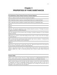
3-2 Phases of a Pure Substance3-3 Phase-Change Processes of Pure SubstancesCompressed Liquid and Saturated LiquidSaturated Vapor and Superheated VaporSaturation Temperature and Saturation PressureSome Consequences of T sat and P sat Dependence3-4 Property Diagrams for Phase-Change Processes1 The T-v Diagram2 The P-v DiagramExtending the Diagrams to Include the Solid Phase3 The P-T DiagramThe P-v-T Surface3-5 Property TablesEnthalpy—A Combination Property1a Saturated Liquid and Saturated Vapor States1b Saturated Liquid–Vapor Mixture2 Superheated Vapor3 Compressed LiquidReference State and Reference Values3-6 The Ideal-Gas Equation of StateIs Water Vapor an Ideal Gas?3-7 Compressibility Factor—A Measure of Deviation from Ideal-GasBehavior3-8 Other Equations of StateVan der Waals Equation of StateBeattie-Bridgeman Equation of StateBenedict-Webb-Rubin Equation of StateVirial Equation of StateTopic of Special InterestVapor Pressure and Phase EquilibriumSummaryReferences and Suggested ReadingProblemsChapter 4Energy Analysis of Closed Systems4-1 Moving Boundary WorkPolytropic Process
4-2 Energy Balance for Closed Systems4-3 Specific Heats4-4 Internal Energy, Enthalpy, and Specific Heats of Ideal GasesSpecific Heat Relations of Ideal Gases4-5 Internal Energy, Enthalpy, and Specific Heat of Solids and LiquidsInternal Energy ChangesEnthalpy ChangesTopic of Special Interest: Thermodynamic Aspects of Biological SystemsSummaryReferences and Suggested ReadingProblemsChapter 5Mass and Energy Analysis of Control Volumes5-1 Conservation of MassMass and Volume Flow RatesConservation of Mass PrincipleMass Balance for Steady-Flow ProcessesSpecial Case: Incompressible Flow5-2 Flow Work and the Energy of a Flowing FluidTotal Energy of a Flowing FluidEnergy Transport by Mass5-3 Energy Analysis of Steady-Flow SystemsEnergy Balance5-4 Some Steady-Flow Engineering Devices1 Nozzles and Diffusers2 Turbines and Compressors3 Throttling Valves4a Mixing Chambers4b Heat Exchangers5 Pipe and Duct Flow5-5 Energy Analysis of Unsteady-Flow ProcessesMass BalanceEnergy BalanceTopic of Special Interest: General Energy EquationSummaryReferences and Suggested ReadingProblems
Chapter 6The Second Law of <strong>Thermodynamics</strong>6-1 Introduction to the Second Law6-2 Thermal Energy Reservoirs6-3 Heat EnginesThermal EfficiencyCan We Save Q out ?The Second Law of <strong>Thermodynamics</strong>: Kelvin–Planck Statement6-5 Refrigerators and Heat PumpsCoefficient of PerformanceHeat PumpsThe Second Law of <strong>Thermodynamics</strong>: Clausius StatementEquivalence of the Two Statements6-6 Perpetual-Motion Machines6-7 Reversible and Irreversible ProcessesIrreversibilitiesInternally and Externally Reversible Processes6-8 The Carnot CycleThe Reversed Carnot Cycle6-9 The Carnot Principles6-10 The Thermodynamic Temperature Scale6-11 The Carnot Heat EngineThe Quality of EnergyQuantity versus Quality in Daily Life6-12 The Carnot Refrigerator and Heat PumpTopics of Special Interest: Household RefrigeratorsSummaryReferences and Suggested ReadingProblemsChapter 7Entropy7-1 EntropyA Special Case: Internally Reversible Isothermal Heat TransferProcesses
7-2 The Increase of Entropy PrincipleSome Remarks about Entropy7-3 Entropy Change of Pure Substances7-4 Isentropic Processes7-5 Property Diagrams Involving Entropy7-6 What Is Entropy?Entropy and Entropy Generation in Daily Life7-7 The T ds Relations7-8 Entropy Change of Liquids and Solids7-9 The Entropy Change of Ideal GasesConstant Specific Heats (Approximate Analysis)Variable Specific Heats (Exact Analysis)Isentropic Processes of Ideal GasesConstant Specific Heats (Approximate Analysis)Variable Specific Heats (Exact Analysis)Relative Pressure and Relative Specific Volume7-10 Reversible Steady-Flow WorkProof that Steady-Flow Devices Deliver the Most and Consume the LeastWork when the Process Is Reversible7-11 Minimizing the Compressor WorkMultistage Compression with Intercooling7-12 Isentropic Efficiencies of Steady-Flow DevicesIsentropic Efficiency of TurbinesIsentropic Efficiencies of Compressors and PumpsIsentropic Efficiency of Nozzles7-13 Entropy BalanceEntropy Change of a System, ∆S systemMechanisms of Entropy Transfer, S in and S out1 Heat Transfer2 Mass FlowEntropy Generation, S genClosed SystemsControl VolumesEntropy Generation Associated with a Heat Transfer ProcessTopics of Special Interest: Reducing the Cost of Compressed AirSummaryReferences and Suggested ReadingProblems
Chapter 8Exergy: A Measure of Work Potential8-1 Exergy: Work Potential of EnergyExergy (Work Potential) Associated with Kinetic and Potential Energy8-2 Reversible Work and Irreversibility8-3 Second-Law Efficiency, η II8-4 Exergy Change of a SystemExergy of a Fixed Mass: Nonflow (or Closed System) ExergyExergy of a Flow Stream: Flow (or Stream) Exergy8-5 Exergy Transfer by Heat, Work, and MassExergy Transfer by Heat Transfer, QExergy Transfer by Work, WExergy Transfer by Mass, m8-6 The Decrease of Exergy Principle and Exergy DestructionExergy Destruction8-7 Exergy Balance: Closed Systems8-8 Exergy Balance: Control VolumesExergy Balance for Steady-Flow SystemsReversible Work, W revSecond-Law Efficiency of Steady-Flow Devices, η IITopics of Special Interest: Second-Law Aspects of Daily LifeSummaryReferences and Suggested ReadingProblemsChapter 9Gas Power Cycles9-1 Basic Considerations in the Analysis of Power Cycles9-2 The Carnot Cycle and Its Value in Engineering9-3 Air-Standard Assumptions9-4 An Overview of Reciprocating Engines9-5 Otto Cycle: The Ideal Cycle for Spark-Ignition Engines9-6 Diesel Cycle: The Ideal Cycle for Compression-Ignition Engines9-7 Stirling and Ericsson Cycles9-8 Brayton Cycle: The Ideal Cycle for Gas-Turbine Engines
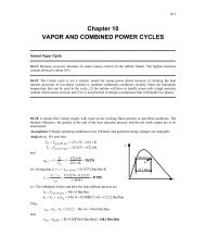
Development of Gas TurbinesDeviation of Actual Gas-Turbine Cycles from Idealized Ones9-9 The Brayton Cycle with Regeneration9-10 The Brayton Cycle with Intercooling, Reheating, and Regeneration9-11 Ideal Jet-Propulsion CyclesModifications to Turbojet Engines9-12 Second-Law Analysis of Gas Power CyclesTopics of Special Interest: Saving Fuel and Money by Driving SensiblySummaryReferences and Suggested ReadingProblemsChapter 10Vapor and Combined Power Cycles10-1 The Carnot Vapor Cycle10-2 Rankine Cycle: The Ideal Cycle for Vapor Power CyclesEnergy Analysis of the Ideal Rankine Cycle10-3 Deviation of Actual Vapor Power Cycles from Idealized Ones10-4 How Can We Increase the Efficiency of the Rankine Cycle?Lowering the Condenser Pressure (Lowers T low,av )Superheating the Steam to High Temperatures (Increases T high,av )Increasing the Boiler Pressure (Increases T high,av )10-5 The Ideal Reheat Rankine Cycle10-6 The Ideal Regenerative Rankine CycleOpen Feedwater HeatersClosed Feedwater Heaters10-7 Second-Law Analysis of Vapor Power Cycles10-8 Cogeneration10-9 Combined Gas–Vapor Power CyclesTopics of Special Interest: Binary Vapor CyclesSummaryReferences and Suggested ReadingProblemsChapter 11Refrigeration Cycles11-1 Refrigerators and Heat Pumps
11-2 The Reversed Carnot Cycle11-3 The Ideal Vapor-Compression Refrigeration Cycle11-4 Actual Vapor-Compression Refrigeration Cycle11-5 Selecting the Right Refrigerant11-6 Heat Pump Systems11-7 Innovative Vapor-Compression Refrigeration SystemsCascade Refrigeration SystemsMultistage Compression Refrigeration SystemsMultipurpose Refrigeration Systems with a Single CompressorLiquefaction of Gases11-8 Gas Refrigeration Cycles11-9 Absorption Refrigeration SystemsTopics of Special Interest: Thermoelectric Power Generation and RefrigerationSystemsSummaryReferences and Suggested ReadingProblemsChapter 12Thermodynamic Property Relations12-1 A Little Math—Partial Derivatives and Associated RelationsPartial DifferentialsPartial Differential Relations12-2 The Maxwell Relations12-3 The Clapeyron Equation12-4 General Relations for du, dh, ds, C v , and C pInternal Energy ChangesEnthalpy ChangesEntropy ChangesSpecific Heats C v and C p12-5 The Joule-Thomson Coefficient12-6 The ∆h, ∆u, and ∆s of Real GasesEnthalpy Changes of Real GasesInternal Energy Changes of Real GasesEntropy Changes of Real GasesSummaryReferences and Suggested Reading
ProblemsChapter 13Gas Mixtures13-1 Composition of a Gas Mixture: Mass and Mole Fractions13-2 P-v-T Behavior of Gas Mixtures: Ideal and Real GasesIdeal-Gas MixturesReal-Gas Mixtures13-3 Properties of Gas Mixtures: Ideal and Real GasesIdeal-Gas MixturesReal-Gas MixturesTopics of Special Interest: Chemical Potential and the Separation Work ofMixturesIdeal Gas Mixtures and Ideal SolutionsMinimum Work of Separation of MixturesReversible Mixing ProcessesSecond-Law EfficiencySpecial-Case: Separation of a Two-Component MixtureAn Application: Desalination ProcessesChapter 14Gas–Vapor Mixtures and Air-Conditioning14-1 Dry and Atmospheric Air14-2 Specific and Relative Humidity of Air14-3 Dew-Point Temperature14-4 Adiabatic Saturation and Wet-Bulb Temperatures14-5 The Psychrometric Chart14-6 Human Comfort and Air-Conditioning14-7 Air-Conditioning ProcessesSimple Heating and Cooling (w = constant)Heating with HumidificationCooling with DehumidificationEvaporative CoolingAdiabatic Mixing of AirstreamsWet Cooling TowersSummary
References and Suggested ReadingProblemsChapter 15Chemical Reactions15-1 Fuels and Combustion15-2 Theoretical and Actual Combustion Processes15-3 Enthalpy of Formation and Enthalpy of Combustion15-4 First-Law Analysis of Reacting SystemsSteady-Flow SystemsClosed Systems15-5 Adiabatic Flame Temperature15-6 Entropy Change of Reacting Systems15-7 Second-Law Analysis of Reacting systemsTopics of Special Interest: Fuel CellsSummaryReferences and Suggested ReadingProblemsChapter 16Chemical and Phase Equilibrium16-1 Criterion for Chemical Equilibrium16-2 The Equilibrium Constant for Ideal-Gas Mixtures16-3 Some Remarks about the K P of Ideal-Gas Mixtures16-4 Chemical Equilibrium for Simultaneous Reactions16-5 Variation of K P with Temperature16-6 Phase EquilibriumPhase Equilibrium for a Single-Component SystemThe Phase RulePhase Equilibrium for a Multicomponent SystemSummaryReferences and Suggested ReadingProblemsChapter 17Compressible Flow
17-1 Stagnation Properties17-2 Speed of Sound and Mach Number17-3 One-Dimensional Isentropic FlowVariation of Fluid Velocity with Flow AreaProperty Relations for Isentropic Flow of Ideal Gases17-4 Isentropic Flow through NozzlesConverging NozzlesConverging–Diverging Nozzles17-5 Shock Waves and ExpansionNormal ShocksOblique ShocksPrandtl–Meyer Expansion Waves17-6 Duct Flow with Heat Transfer and Negligible Friction (Rayleigh Flow)Property Relations for Rayleigh FlowChoked Rayleigh Flow17-7 Steam NozzlesSummaryReferences and Suggested ReadingProblemsAppendix 1Property Tables and Charts (SI Units)Table A-1Table A-2Table A-3Table A-4Table A-5Table A-6Table A-7Molar mass, gas constant, and critical-point propertiesIdeal-gas specific heats of various common gasesProperties of common liquids, solids, and foodsSaturated water—Temperature tableSaturated water—Pressure tableSuperheated waterCompressed liquid water
Table A-27 Properties of some common fuels and hydrocarbonsTable A-28 Natural Logarithms of the equilibrium constant K pFigure A-29 Generalized enthalpy departure chartFigure A-30 Generalized entropy departure chartFigure A-31 Psychrometric chart at 1 atm total pressureTable A-32 One-dimensional isentropic compressible-flow functions for anideal gas with k = 1.4Table A-33 One-dimensional normal-shock functions for an ideal gas with k=1.4Table A-34 Rayleigh flow functions for an ideal gas with k = 1.4
Appendix 2Property Tables and Charts (English Units)Table A-1E Molar mass, gas constant, and critical-point propertiesTable A-2E Ideal-gas specific heats of various common gasesTable A-3E Properties of common liquids, solids, and foodsTable A-4E Saturated water—Temperature tableTable A-5E Saturated water—Pressure tableTable A-6E Superheated waterTable A-7E Compressed liquid waterTable A-8E Saturated ice—water vaporFigure A-9E T-s diagram for waterFigure A-10E Mollier diagram for waterTable A-11E Saturated refrigerant-134a—Temperature tableTable A-12E Saturated refrigerant-134a—Pressure tableTable A-13E Superheated refrigerant-134aFigure A-14E P-h diagram for refrigerant-134aTable A-15ETable A-16E Properties of the atomosphere at high altitudeTable A-17E Ideal-gas properties of air
Table A-18E Ideal-gas properties of nitrogen, N 2Table A-19E Ideal-gas properties of oxygen, O 2Table A-20E Ideal-gas properties of carbon dioxide, CO 2Table A-21E Ideal-gas properties of carbon monoxide, COTable A-22E Ideal-gas properties of hydrogen, H 2Table A-23E Ideal-gas properties of water vapor, H 2 OTable A-24ETable A-25ETable A-26E Enthalpy of formation, Gibbs function of formation, andabsolute entropy at 77°C, 1 atmTable A-27E Properties of some common fuels and hydrocarbonsFigure A-31E Psycrometric chart at 1 atm total pressure
PREFACEBACKGROUND<strong>Thermodynamics</strong> is an exciting and fascinating subject that deals withenergy, which is essential for sustenance of life, and thermodynamics haslong been an essential part of engineering curricula all over the world. It hasa broad application area ranging from microscopic organisms to commonhousehold appliances, transportation vehicles, power generation systems,and even philosophy. This introductory book contains sufficient material fortwo sequential courses in thermodynamics. Students are assumed to have anadequate background in calculus and physics.OBJECTIVESThis book is intended for use as a textbook by undergraduate engineeringstudents in their sophomore or junior year, and as a reference book for practicingengineers. The objectives of this text are• To cover the basic principles of thermodynamics.• To present a wealth of real-world engineering examples to givestudents a feel for how thermodynamics is applied in engineeringpractice.• To develop an intuitive understanding of thermodynamics by emphasizingthe physics and physical arguments.It is our hope that this book, through its careful explanations of conceptsand its use of numerous practical examples and figures, helps studentsdevelop the necessary skills to bridge the gap between knowledge and theconfidence to properly apply knowledge.PHILOSOPHY AND GOALThe philosophy that contributed to the overwhelming popularity of the prioreditions of this book has remained unchanged in this edition. Namely, ourgoal has been to offer an engineering textbook that• Communicates directly to the minds of tomorrow’s engineers in asimple yet precise manner.• Leads students toward a clear understanding and firm grasp of thebasic principles of thermodynamics.• Encourages creative thinking and development of a deeper understandingand intuitive feel for thermodynamics.• Is read by students with interest and enthusiasm rather than beingused as an aid to solve problems.| xvii
xviii | PrefaceSpecial effort has been made to appeal to students’ natural curiosity andto help them explore the various facets of the exciting subject area of thermodynamics.The enthusiastic responses we have received from users ofprior editions—from small colleges to large universities all over the world—indicate that our objectives have largely been achieved. It is our philosophythat the best way to learn is by practice. Therefore, special effort is madethroughout the book to reinforce material that was presented earlier.Yesterday’s engineer spent a major portion of his or her time substitutingvalues into the formulas and obtaining numerical results. However, formulamanipulations and number crunching are now being left mainly to computers.Tomorrow’s engineer will need a clear understanding and a firm grasp ofthe basic principles so that he or she can understand even the most complexproblems, formulate them, and interpret the results. A conscious effort ismade to emphasize these basic principles while also providing students witha perspective of how computational tools are used in engineering practice.The traditional classical, or macroscopic, approach is used throughout thetext, with microscopic arguments serving in a supporting role as appropriate.This approach is more in line with students’ intuition and makes learningthe subject matter much easier.NEW IN THIS EDITIONAll the popular features of the previous editions are retained while new onesare added. With the exception of reorganizing the first law coverage andupdating the steam and refrigerant properties, the main body of the textremains largely unchanged. The most significant changes in this fifth editionare highlighted below.EARLY INTRODUCTION OF THE FIRST LAW OF THERMODYNAMICSThe first law of thermodynamics is now introduced early in the new Chapter2, “Energy, Energy Transfer, and General Energy Analysis.” This introductorychapter sets the framework of establishing a general understanding ofvarious forms of energy, mechanisms of energy transfer, the concept ofenergy balance, thermo-economics, energy conversion, and conversion efficiencyusing familiar settings that involve mostly electrical and mechanicalforms of energy. It also exposes students to some exciting real-world applicationsof thermodynamics early in the course, and helps them establish asense of the monetary value of energy.SEPARATE COVERAGE OF CLOSED SYSTEMSAND CONTROL VOLUME ENERGY ANALYSESThe energy analysis of closed systems is now presented in a separate chapter,Chapter 4, together with the boundary work and the discussion ofspecific heats for both ideal gases and incompressible substances. The conservationof mass is now covered together with conservation of energy innew Chapter 5. A formal derivation of the general energy equation is alsogiven in this chapter as the Topic of Special Interest.REVISED COVERAGE OF COMPRESSIBLE FLOWThe chapter on compressible flow that deals with compressibility effects(now Chapter 17) is greatly revised and expanded. This chapter now includes
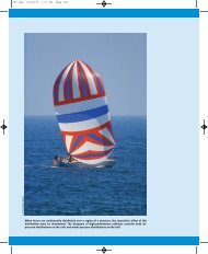
Preface | xixcoverage of oblique shocks and flow with heat transfer (Rayleigh flow) withsome exciting photographs and extended discussions of shock waves.UPDATED STEAM AND REFRIGERANT-134A TABLESThe steam and refrigerant-134a tables are updated using the most currentproperty data from EES. Tables A-4 through A-8 and A-11 through A-13, aswell as their counterparts in English units, have all been revised. All the examplesand homework problems in the text that involve steam or refrigerant-134a are also revised to reflect the small changes in steam and refrigerantproperties. An added advantage of this update is that students will get thesame result when solving problems whether they use steam or refrigerantproperties from EES or property tables in the appendices.OVER 300 NEW COMPREHENSIVE PROBLEMSThis edition includes over 300 new comprehensive problems that comemostly from industrial applications. Problems whose solutions require parametricinvestigations, and thus the use of a computer, are identified by acomputer-EES icon, as before.CONTENT CHANGES AND REORGANIZATIONThe noteworthy changes in various chapters are summarized below forthose who are familiar with the previous edition.• Chapter 1 is greatly revised, and its title is changed to “Introductionand Basic Concepts.” A new section Density and Specific Gravity anda new subsection The International Temperature Scale of 1990 areadded. The sections Forms of Energy and Energy and the Environmentare moved to new Chapter 2, and the Topic of Special Interest ThermodynamicAspects of Biological Systems is moved to new Chapter 4.• The new Chapter 2 “Energy, Energy Transfer, and General EnergyAnalysis” mostly consists of the sections Forms of Energy and Energyand the Environment moved from Chapter 1, Energy Transfer by Heatand Energy Transfer by Work, and Mechanical Forms of Energy fromChapter 3, The First Law of <strong>Thermodynamics</strong> from Chapter 4, andEnergy Conversion Efficiencies from Chapter 5. The Topic of SpecialInterest in this chapter is Mechanisms of Heat Transfer moved fromChapter 3.• Chapter 3 “Properties of Pure Substance” is essentially the previousedition Chapter 2, except that the last three sections on specific heatsare moved to new Chapter 4.• Chapter 4 “Energy Analysis of Closed Systems” consists of MovingBoundary Work from Chapter 3, sections on Specific Heats fromChapter 2, and Energy Balance for Closed Systems from Chapter 4.Also, the Topic of Special Interest Thermodynamic Aspects of BiologicalSystems is moved here from Chapter 1.• Chapter 5 “Mass and Energy Analysis of Control Volumes” consistsof Mass Balance for Control Volumes and Flow Work and the Energyof a Flowing Fluid from Chapter 3 and the sections on EnergyBalance for Steady- and Unsteady-Flow Systems from Chapter 4. The
xx | PrefaceTopic of Special Interest Refrigeration and Freezing of Foods isdeleted and is replaced by a formal derivation of the General EnergyEquation.• Chapter 6 “The Second Law of <strong>Thermodynamics</strong>” is identical to theprevious edition Chapter 5, except the section Energy ConversionEfficiencies is moved to Chapter 2.• Chapters 7 through 15 are essentially identical to the previous editionChapters 6 through 14, respectively.• Chapter 17 “Compressible Flow” is an updated version of the previousedition Chapter 16. The entire chapter is greatly revised, the sectionFlow Through Actual Nozzles and Diffusers is deleted, and a newsection Duct Flow with Heat Transfer and Negligible Friction(Rayleigh Flow) is added.• In Appendices 1 and 2, the steam and refrigerant-134a tables (Tables4 through 8 and 11 through 13) are entirely revised, but the tablenumbers are kept the same. The tables for isentropic compressibleflow functions and the normal shock functions (Tables A-32 andA-33) are updated and plots of functions are now included. Also,Rayleigh flow functions are added as Table A-34. Appendix 3 Introductionto EES is moved to the Student Resources DVD that comespackaged free with the text.• The conversion factors on the inner cover pages and the physical constantsare updated, and some nomenclature symbols are revised.LEARNING TOOLSEMPHASIS ON PHYSICSA distinctive feature of this book is its emphasis on the physical aspects ofthe subject matter in addition to mathematical representations and manipulations.The authors believe that the emphasis in undergraduate educationshould remain on developing a sense of underlying physical mechanismsand a mastery of solving practical problems that an engineer is likely to facein the real world. Developing an intuitive understanding should also makethe course a more motivating and worthwhile experience for students.EFFECTIVE USE OF ASSOCIATIONAn observant mind should have no difficulty understanding engineering sciences.After all, the principles of engineering sciences are based on oureveryday experiences and experimental observations. Therefore, a physical,intuitive approach is used throughout this text. Frequently, parallels aredrawn between the subject matter and students’ everyday experiences sothat they can relate the subject matter to what they already know. Theprocess of cooking, for example, serves as an excellent vehicle to demonstratethe basic principles of thermodynamics.SELF-INSTRUCTINGThe material in the text is introduced at a level that an average student canfollow comfortably. It speaks to students, not over students. In fact, it isself-instructive. The order of coverage is from simple to general. That is, it
starts with the simplest case and adds complexities gradually. In this way,the basic principles are repeatedly applied to different systems, and studentsmaster how to apply the principles instead of how to simplify a general formula.Noting that the principles of sciences are based on experimentalobservations, all the derivations in this text are based on physical arguments,and thus they are easy to follow and understand.EXTENSIVE USE OF ARTWORKFigures are important learning tools that help students “get the picture,” andthe text makes very effective use of graphics. The fifth edition of <strong>Thermodynamics</strong>:An Engineering Approach contains more figures and illustrationsthan any other book in this category. This edition incorporates an expandedphoto program and updated art style. Figures attract attention and stimulatecuriosity and interest. Most of the figures in this text are intended to serveas a means of emphasizing some key concepts that would otherwise gounnoticed; some serve as page summaries. The popular cartoon feature“Blondie” is used to make some important points in a humorous way andalso to break the ice and ease the nerves. Who says studying thermodynamicscan’t be fun?LEARNING OBJECTIVES AND SUMMARIESEach chapter begins with an overview of the material to be covered andchapter-specific learning objectives. A summary is included at the end ofeach chapter, providing a quick review of basic concepts and important relations,and pointing out the relevance of the material.NUMEROUS WORKED-OUT EXAMPLESWITH A SYSTEMATIC SOLUTIONS PROCEDUREEach chapter contains several worked-out examples that clarify the materialand illustrate the use of the basic principles. An intuitive and systematicapproach is used in the solution of the example problems, while maintainingan informal conversational style. The problem is first stated, and the objectivesare identified. The assumptions are then stated, together with their justifications.The properties needed to solve the problem are listed separately,if appropriate. Numerical values are used together with their units to emphasizethat numbers without units are meaningless, and that unit manipulationsare as important as manipulating the numerical values with a calculator. Thesignificance of the findings is discussed following the solutions. Thisapproach is also used consistently in the solutions presented in the instructor’ssolutions manual.A WEALTH OF REAL-WORLD END-OF-CHAPTER PROBLEMSThe end-of-chapter problems are grouped under specific topics to makeproblem selection easier for both instructors and students. Within eachgroup of problems are Concept Questions, indicated by “C,” to check thestudents’ level of understanding of basic concepts. The problems underReview Problems are more comprehensive in nature and are not directly tiedto any specific section of a chapter—in some cases they require review ofmaterial learned in previous chapters. Problems designated as Design andEssay are intended to encourage students to make engineering judgments, toconduct independent exploration of topics of interest, and to communicatePreface | xxi
xxii | Prefacetheir findings in a professional manner. Problems designated by an “E” arein English units, and SI users can ignore them. Problems with the aresolved using EES, and complete solutions together with parametric studiesare included on the enclosed DVD. Problems with the are comprehensivein nature and are intended to be solved with a computer, preferablyusing the EES software that accompanies this text. Several economics- andsafety-related problems are incorporated throughout to enhance cost andsafety awareness among engineering students. Answers to selected problemsare listed immediately following the problem for convenience to students. Inaddition, to prepare students for the Fundamentals of Engineering Exam(that is becoming more important for the outcome-based ABET 2000 criteria)and to facilitate multiple-choice tests, over 200 multiple-choice problemsare included in the end-of-chapter problem sets. They are placed underthe title Fundamentals of Engineering (FE) Exam Problems for easy recognition.These problems are intended to check the understanding of fundamentalsand to help readers avoid common pitfalls.RELAXED SIGN CONVENTIONThe use of a formal sign convention for heat and work is abandoned as itoften becomes counterproductive. A physically meaningful and engagingapproach is adopted for interactions instead of a mechanical approach. Subscripts“in” and “out,” rather than the plus and minus signs, are used to indicatethe directions of interactions.PHYSICALLY MEANINGFUL FORMULASThe physically meaningful forms of the balance equations rather than formulasare used to foster deeper understanding and to avoid a cookbookapproach. The mass, energy, entropy, and exergy balances for any systemundergoing any process are expressed asMass balance:Energy balance:Entropy balance:Exergy balance:m in m out ¢m systemE in E out ¢E system⎫ ⎪⎬⎪⎭⎫⎪⎬⎪⎭⎫⎬⎭⎫ ⎪⎬⎪⎭⎫⎪⎬⎪⎭⎫⎪⎬⎪⎭⎫ ⎪⎬⎪⎭⎫⎪⎬⎪⎭Net energy transferby heat, work, and massChange in internal, kinetic,potential, etc., energiesS in S out S gen ¢S systemNet entropy transfer Entropy Changeby heat and mass generation in entropyX in X out X destroyed ¢X systemNet exergy transfer Exergy Changeby heat, work, and mass destruction in exergyThese relations reinforce the fundamental principles that during an actualprocess mass and energy are conserved, entropy is generated, and exergy isdestroyed. Students are encouraged to use these forms of balances in earlychapters after they specify the system, and to simplify them for the particularproblem. A more relaxed approach is used in later chapters as studentsgain mastery.
A CHOICE OF SI ALONE OR SI/ENGLISH UNITSIn recognition of the fact that English units are still widely used in someindustries, both SI and English units are used in this text, with an emphasison SI. The material in this text can be covered using combined SI/Englishunits or SI units alone, depending on the preference of the instructor. Theproperty tables and charts in the appendices are presented in both units,except the ones that involve dimensionless quantities. Problems, tables, andcharts in English units are designated by “E” after the number for easyrecognition, and they can be ignored by SI users.Preface | xxiiiTOPICS OF SPECIAL INTERESTMost chapters contain a section called “Topic of Special Interest” whereinteresting aspects of thermodynamics are discussed. Examples includeThermodynamic Aspects of Biological Systems in Chapter 4, HouseholdRefrigerators in Chapter 6, Second-Law Aspects of Daily Life in Chapter 8,and Saving Fuel and Money by Driving Sensibly in Chapter 9. The topicsselected for these sections provide intriguing extensions to thermodynamics,but they can be ignored if desired without a loss in continuity.GLOSSARY OF THERMODYNAMIC TERMSThroughout the chapters, when an important key term or concept is introducedand defined, it appears in boldface type. Fundamental thermodynamicterms and concepts also appear in a glossary located on ouraccompanying website (www.mhhe.com/cengel). This unique glossary helpsto reinforce key terminology and is an excellent learning and review tool forstudents as they move forward in their study of thermodynamics. In addition,students can test their knowledge of these fundamental terms by usingthe flash cards and other interactive resources.CONVERSION FACTORSFrequently used conversion factors and physical constants are listed on theinner cover pages of the text for easy reference.SUPPLEMENTSThe following supplements are available to the adopters of the book.STUDENT RESOURCES DVDPackaged free with every new copy of the text, this DVD provides a wealthof resources for students including Physical Experiments in <strong>Thermodynamics</strong>,an Interactive <strong>Thermodynamics</strong> Tutorial, and EES Software.Physical Experiments in <strong>Thermodynamics</strong>: A new feature of this book isthe addition of Physical Experiments in <strong>Thermodynamics</strong> created by RonaldMullisen of the Mechanical Engineering Department at California PolytechnicState University (Cal Poly), San Luis Obispo. At appropriate places in themargins of Chapters 1, 3, and 4, photos with captions show physical experimentsthat directly relate to material covered on that page. The captions
xxiv | Prefacerefer the reader to end-of-chapter problems that give a brief description ofthe experiments. These experiments cover thermodynamic properties, thermodynamicprocesses, and thermodynamic laws. The Student ResourcesDVD contains complete coverage of the nine experiments. Each experimentcontains a video clip, a complete write-up including historical background,and actual data (usually in an Excel file). The results are also provided onthe website that accompanies the text, and they are password protected forinstructor use. After viewing the video and reading the write-up, the studentwill be ready to reduce the data and obtain results that directly connect withmaterial presented in the chapters. For all of the experiments the finalresults are compared against published information. Most of the experimentsgive final results that come within 10 percent or closer to these publishedvalues.Interactive <strong>Thermodynamics</strong> Tutorial: Also included on the StudentResources DVD is the Interactive <strong>Thermodynamics</strong> Tutorial developed byEd Anderson of Texas Tech University. The revised tutorial is now tieddirectly to the text with an icon to indicate when students should refer tothe tutorial to further explore specific topics such as energy balance andisentropic processes.Engineering Equation Solver (EES): Developed by Sanford Klein andWilliam Beckman from the University of Wisconsin–Madison, this softwarecombines equation-solving capability and engineering property data. EEScan do optimization, parametric analysis, and linear and nonlinear regression,and provides publication-quality plotting capabilities. <strong>Thermodynamics</strong>and transport properties for air, water, and many other fluids are built in,and EES allows the user to enter property data or functional relationships.ONLINE LEARNING CENTER (OLC)Web support is provided for the book on our Online Learning Center atwww.mhhe.com/cengel. Visit this robust site for book and supplement information,errata, author information, and further resources for instructors andstudents.INSTRUCTOR’S RESOURCE CD-ROM(AVAILABLE TO INSTRUCTORS ONLY)This CD, available to instructors only, offers a wide range of classroompreparation and presentation resources including the solutions manual inPDF files by chapter, all text chapters and appendices as downloadable PDFfiles, and all text figures in JPEG format.COSMOS CD-ROM (COMPLETE ONLINE SOLUTIONSMANUAL ORGANIZATION SYSTEM)(AVAILABLE TO INSTRUCTORS ONLY)This CD, available to instructors only, provides electronic solutions deliveredvia our database management tool. McGraw-Hill’s COSMOS allowsinstructors to streamline the creation of assignments, quizzes, and tests byusing problems and solutions from the textbook—as well as their own custommaterial.
Chapter 1INTRODUCTION AND BASIC CONCEPTSEvery science has a unique vocabulary associated withit, and thermodynamics is no exception. Precise definitionof basic concepts forms a sound foundation forthe development of a science and prevents possible misunderstandings.We start this chapter with an overview of thermodynamicsand the unit systems, and continue with adiscussion of some basic concepts such as system, state,state postulate, equilibrium, and process. We also discusstemperature and temperature scales with particular emphasison the International Temperature Scale of 1990. We then presentpressure, which is the normal force exerted by a fluidper unit area and discuss absolute and gage pressures, thevariation of pressure with depth, and pressure measurementdevices, such as manometers and barometers. Careful studyof these concepts is essential for a good understanding of thetopics in the following chapters. Finally, we present an intuitivesystematic problem-solving technique that can be usedas a model in solving engineering problems.ObjectivesThe objectives of Chapter 1 are to:• Identify the unique vocabulary associated withthermodynamics through the precise definition of basicconcepts to form a sound foundation for the developmentof the principles of thermodynamics.• Review the metric SI and the English unit systems that willbe used throughout the text.• Explain the basic concepts of thermodynamics suchas system, state, state postulate, equilibrium, process,and cycle.• Review concepts of temperature, temperature scales,pressure, and absolute and gage pressure.• Introduce an intuitive systematic problem-solvingtechnique.| 1
2 | <strong>Thermodynamics</strong>PE = 10 unitsKE = 0PE = 7 unitsKE = 3 unitsPotentialenergyKineticenergyFIGURE 1–1Energy cannot be created ordestroyed; it can only change forms(the first law).Energy in(5 units)INTERACTIVETUTORIALSEE TUTORIAL CH. 1, SEC. 1 ON THE DVD.Energy storage(1 unit)Energy out(4 units)FIGURE 1–2Conservation of energy principle forthe human body.1–1 ■ THERMODYNAMICS AND ENERGY<strong>Thermodynamics</strong> can be defined as the science of energy. Although everybodyhas a feeling of what energy is, it is difficult to give a precise definitionfor it. Energy can be viewed as the ability to cause changes.The name thermodynamics stems from the Greek words therme (heat) anddynamis (power), which is most descriptive of the early efforts to convertheat into power. Today the same name is broadly interpreted to include allaspects of energy and energy transformations, including power generation,refrigeration, and relationships among the properties of matter.One of the most fundamental laws of nature is the conservation of energyprinciple. It simply states that during an interaction, energy can change fromone form to another but the total amount of energy remains constant. That is,energy cannot be created or destroyed. A rock falling off a cliff, for example,picks up speed as a result of its potential energy being converted to kineticenergy (Fig. 1–1). The conservation of energy principle also forms the backboneof the diet industry: A person who has a greater energy input (food)than energy output (exercise) will gain weight (store energy in the form offat), and a person who has a smaller energy input than output will loseweight (Fig. 1–2). The change in the energy content of a body or any othersystem is equal to the difference between the energy input and the energyoutput, and the energy balance is expressed as E in E out E.The first law of thermodynamics is simply an expression of the conservationof energy principle, and it asserts that energy is a thermodynamicproperty. The second law of thermodynamics asserts that energy has qualityas well as quantity, and actual processes occur in the direction ofdecreasing quality of energy. For example, a cup of hot coffee left on a tableeventually cools, but a cup of cool coffee in the same room never gets hotby itself (Fig. 1–3). The high-temperature energy of the coffee is degraded(transformed into a less useful form at a lower temperature) once it is transferredto the surrounding air.Although the principles of thermodynamics have been in existence sincethe creation of the universe, thermodynamics did not emerge as a scienceuntil the construction of the first successful atmospheric steam engines inEngland by Thomas Savery in 1697 and Thomas Newcomen in 1712. Theseengines were very slow and inefficient, but they opened the way for thedevelopment of a new science.The first and second laws of thermodynamics emerged simultaneously inthe 1850s, primarily out of the works of William Rankine, Rudolph Clausius,and Lord Kelvin (formerly William Thomson). The term thermodynamicswas first used in a publication by Lord Kelvin in 1849. The firstthermodynamic textbook was written in 1859 by William Rankine, a professorat the University of Glasgow.It is well-known that a substance consists of a large number of particlescalled molecules. The properties of the substance naturally depend on thebehavior of these particles. For example, the pressure of a gas in a containeris the result of momentum transfer between the molecules and the walls ofthe container. However, one does not need to know the behavior of the gas
particles to determine the pressure in the container. It would be sufficient toattach a pressure gage to the container. This macroscopic approach to thestudy of thermodynamics that does not require a knowledge of the behaviorof individual particles is called classical thermodynamics. It provides adirect and easy way to the solution of engineering problems. A more elaborateapproach, based on the average behavior of large groups of individualparticles, is called statistical thermodynamics. This microscopic approachis rather involved and is used in this text only in the supporting role.Application Areas of <strong>Thermodynamics</strong>All activities in nature involve some interaction between energy and matter;thus, it is hard to imagine an area that does not relate to thermodynamics insome manner. Therefore, developing a good understanding of basic principlesof thermodynamics has long been an essential part of engineering education.<strong>Thermodynamics</strong> is commonly encountered in many engineering systemsand other aspects of life, and one does not need to go very far to see someapplication areas of it. In fact, one does not need to go anywhere. The heartis constantly pumping blood to all parts of the human body, various energyconversions occur in trillions of body cells, and the body heat generated isconstantly rejected to the environment. The human comfort is closely tied tothe rate of this metabolic heat rejection. We try to control this heat transferrate by adjusting our clothing to the environmental conditions.Other applications of thermodynamics are right where one lives. An ordinaryhouse is, in some respects, an exhibition hall filled with wonders ofthermodynamics (Fig. 1–4). Many ordinary household utensils and appliancesare designed, in whole or in part, by using the principles of thermodynamics.Some examples include the electric or gas range, the heating andair-conditioning systems, the refrigerator, the humidifier, the pressurecooker, the water heater, the shower, the iron, and even the computer andthe TV. On a larger scale, thermodynamics plays a major part in the designand analysis of automotive engines, rockets, jet engines, and conventional ornuclear power plants, solar collectors, and the design of vehicles from ordinarycars to airplanes (Fig. 1–5). The energy-efficient home that you may beliving in, for example, is designed on the basis of minimizing heat loss inwinter and heat gain in summer. The size, location, and the power input ofthe fan of your computer is also selected after an analysis that involvesthermodynamics.1–2 ■ IMPORTANCE OF DIMENSIONS AND UNITSAny physical quantity can be characterized by dimensions. The magnitudesassigned to the dimensions are called units. Some basic dimensions such asmass m, length L, time t, and temperature T are selected as primary or fundamentaldimensions, while others such as velocity V, energy E, and volumeV are expressed in terms of the primary dimensions and are calledsecondary dimensions, or derived dimensions.FIGURE 1–3Hotcoffee70°CChapter 1 | 3Heat flows in the direction ofdecreasing temperature.ShowerHotwaterColdwaterHeatexchangerSolarcollectorsHot water tankPumpCoolenvironment20°CHeatFIGURE 1–4The design of many engineeringsystems, such as this solar hot watersystem, involves thermodynamics.INTERACTIVETUTORIALSEE TUTORIAL CH. 1, SEC. 2 ON THE DVD.
4 | <strong>Thermodynamics</strong>The human body Air conditioning systems AirplanesCar radiators Power plants Refrigeration systemsFIGURE 1–5Some application areas of thermodynamics.A/C unit, fridge, radiator: © The McGraw-Hill Companies, Inc./Jill Braaten, photographer; Plane: © Vol. 14/PhotoDisc; Humans: © Vol.121/PhotoDisc; Power plant: © Corbis Royalty FreeA number of unit systems have been developed over the years. Despitestrong efforts in the scientific and engineering community to unify theworld with a single unit system, two sets of units are still in common usetoday: the English system, which is also known as the United States CustomarySystem (USCS), and the metric SI (from Le Système International d’Unités), which is also known as the International System. The SI is a simpleand logical system based on a decimal relationship between the variousunits, and it is being used for scientific and engineering work in most of theindustrialized nations, including England. The English system, however, hasno apparent systematic numerical base, and various units in this system arerelated to each other rather arbitrarily (12 in 1 ft, 1 mile 5280 ft, 4 qt gal, etc.), which makes it confusing and difficult to learn. The UnitedStates is the only industrialized country that has not yet fully converted tothe metric system.The systematic efforts to develop a universally acceptable system ofunits dates back to 1790 when the French National Assembly charged theFrench Academy of Sciences to come up with such a unit system. Anearly version of the metric system was soon developed in France, but it
did not find universal acceptance until 1875 when The Metric ConventionTreaty was prepared and signed by 17 nations, including the UnitedStates. In this international treaty, meter and gram were established as themetric units for length and mass, respectively, and a General Conferenceof Weights and Measures (CGPM) was established that was to meet everysix years. In 1960, the CGPM produced the SI, which was based on sixfundamental quantities, and their units were adopted in 1954 at the TenthGeneral Conference of Weights and Measures: meter (m) for length, kilogram(kg) for mass, second (s) for time, ampere (A) for electric current,degree Kelvin (°K) for temperature, and candela (cd) for luminous intensity(amount of light). In 1971, the CGPM added a seventh fundamentalquantity and unit: mole (mol) for the amount of matter.Based on the notational scheme introduced in 1967, the degree symbolwas officially dropped from the absolute temperature unit, and all unitnames were to be written without capitalization even if they were derivedfrom proper names (Table 1–1). However, the abbreviation of a unit was tobe capitalized if the unit was derived from a proper name. For example, theSI unit of force, which is named after Sir Isaac Newton (1647–1723), isnewton (not Newton), and it is abbreviated as N. Also, the full name of aunit may be pluralized, but its abbreviation cannot. For example, the lengthof an object can be 5 m or 5 meters, not 5 ms or 5 meter. Finally, no periodis to be used in unit abbreviations unless they appear at the end of a sentence.For example, the proper abbreviation of meter is m (not m.).The recent move toward the metric system in the United States seems tohave started in 1968 when Congress, in response to what was happening inthe rest of the world, passed a Metric Study Act. Congress continued topromote a voluntary switch to the metric system by passing the MetricConversion Act in 1975. A trade bill passed by Congress in 1988 set aSeptember 1992 deadline for all federal agencies to convert to the metricsystem. However, the deadlines were relaxed later with no clear plans forthe future.The industries that are heavily involved in international trade (such as theautomotive, soft drink, and liquor industries) have been quick in converting tothe metric system for economic reasons (having a single worldwide design,fewer sizes, smaller inventories, etc.). Today, nearly all the cars manufacturedin the United States are metric. Most car owners probably do not realize thisuntil they try an English socket wrench on a metric bolt. Most industries,however, resisted the change, thus slowing down the conversion process.Presently the United States is a dual-system society, and it will stay thatway until the transition to the metric system is completed. This puts an extraburden on today’s engineering students, since they are expected to retaintheir understanding of the English system while learning, thinking, andworking in terms of the SI. Given the position of the engineers in the transitionperiod, both unit systems are used in this text, with particular emphasison SI units.As pointed out, the SI is based on a decimal relationship between units.The prefixes used to express the multiples of the various units are listed inTable 1–2. They are standard for all units, and the student is encouraged tomemorize them because of their widespread use (Fig. 1–6).TABLE 1–1Chapter 1 | 5The seven fundamental (or primary)dimensions and their units in SIDimensionLengthMassTimeTemperatureElectric currentAmount of lightAmount of matterTABLE 1–2Standard prefixes in SI unitsMultiplePrefixUnitmeter (m)kilogram (kg)second (s)kelvin (K)ampere (A)candela (cd)mole (mol)10 12 tera, T10 9 giga, G10 6 mega, M10 3 kilo, k10 2 hecto, h10 1 deka, da10 1 deci, d10 2 centi, c10 3 milli, m10 6 micro, m10 9 nano, n10 12 pico, p
6 | <strong>Thermodynamics</strong>FIGURE 1–6The SI unit prefixes are used in allbranches of engineering.200 mL(0.2 L)1 kg(10 3 g)1 M(10 6 )m = 1 kgm = 32.174 lbma = 1 m/s 2a = 1 ft/s 2F = 1 NFIGURE 1–7The definition of the force units.1 applem = 102 g1 N10 applesm = 1 kg1 kgfF = 1 lbf4 applesm = 1 lbm1 lbfFIGURE 1–8The relative magnitudes of the forceunits newton (N), kilogram-force(kgf), and pound-force (lbf).Some SI and English UnitsIn SI, the units of mass, length, and time are the kilogram (kg), meter (m),and second (s), respectively. The respective units in the English system arethe pound-mass (lbm), foot (ft), and second (s). The pound symbol lb isactually the abbreviation of libra, which was the ancient Roman unit ofweight. The English retained this symbol even after the end of the Romanoccupation of Britain in 410. The mass and length units in the two systemsare related to each other by1 lbm 0.45359 kg1 ft 0.3048 mIn the English system, force is usually considered to be one of the primarydimensions and is assigned a nonderived unit. This is a source of confusionand error that necessitates the use of a dimensional constant (g c ) inmany formulas. To avoid this nuisance, we consider force to be a secondarydimension whose unit is derived from Newton’s second law, that is,Force 1Mass2 1Acceleration2orF ma(1–1)In SI, the force unit is the newton (N), and it is defined as the force requiredto accelerate a mass of 1 kg at a rate of 1 m/s 2 . In the English system, theforce unit is the pound-force (lbf) and is defined as the force required toaccelerate a mass of 32.174 lbm (1 slug) at a rate of 1 ft/s 2 (Fig. 1–7). Thatis,1 N 1 kg # m>s21 lbf 32.174 lbm # ft>s2A force of 1 N is roughly equivalent to the weight of a small apple (m 102 g), whereas a force of 1 lbf is roughly equivalent to the weight of fourmedium apples (m total 454 g), as shown in Fig. 1–8. Another force unit incommon use in many European countries is the kilogram-force (kgf), whichis the weight of 1 kg mass at sea level (1 kgf 9.807 N).The term weight is often incorrectly used to express mass, particularly bythe “weight watchers.” Unlike mass, weight W is a force. It is the gravitationalforce applied to a body, and its magnitude is determined from Newton’ssecond law,W mg1N2(1–2)
1 J 1 N # m (1–3)Chapter 1 | 7where m is the mass of the body, and g is the local gravitational acceleration(g is 9.807 m/s 2 or 32.174 ft/s 2 at sea level and 45° latitude). An ordinarybathroom scale measures the gravitational force acting on a body. Theweight of a unit volume of a substance is called the specific weight g and isdetermined from g rg, where r is density.The mass of a body remains the same regardless of its location in the universe.Its weight, however, changes with a change in gravitational acceleration.A body weighs less on top of a mountain since g decreases withaltitude. On the surface of the moon, an astronaut weighs about one-sixth ofwhat she or he normally weighs on earth (Fig. 1–9).At sea level a mass of 1 kg weighs 9.807 N, as illustrated in Fig. 1–10. Amass of 1 lbm, however, weighs 1 lbf, which misleads people to believe thatpound-mass and pound-force can be used interchangeably as pound (lb),which is a major source of error in the English system.It should be noted that the gravity force acting on a mass is due to theattraction between the masses, and thus it is proportional to the magnitudesof the masses and inversely proportional to the square of the distancebetween them. Therefore, the gravitational acceleration g at a location FIGURE 1–9depends on the local density of the earth’s crust, the distance to the center A body weighing 150 lbf on earth willof the earth, and to a lesser extent, the positions of the moon and the sun. weigh only 25 lbf on the moon.The value of g varies with location from 9.8295 m/s 2 at 4500 m below sealevel to 7.3218 m/s 2 at 100,000 m above sea level. However, at altitudes upto 30,000 m, the variation of g from the sea-level value of 9.807 m/s 2 is lessthan 1 percent. Therefore, for most practical purposes, the gravitationalacceleration can be assumed to be constant at 9.81 m/s 2 . It is interesting tonote that at locations below sea level, the value of g increases with distancefrom the sea level, reaches a maximum at about 4500 m, and then startsdecreasing. (What do you think the value of g is at the center of the earth?)The primary cause of confusion between mass and weight is that mass isusually measured indirectly by measuring the gravity force it exerts. Thiskgg = 9.807 m/s 2lbmg = 32.174 ft/s 2approach also assumes that the forces exerted by other effects such as air W = 9.807 kg · m/s 2 W = 32.174 lbm · ft/s 2= 9.807 N= 1 lbfbuoyancy and fluid motion are negligible. This is like measuring the distanceto a star by measuring its red shift, or measuring the altitude of an air-= 1 kgfplane by measuring barometric pressure. Both of these are also indirectmeasurements. The correct direct way of measuring mass is to compare it toa known mass. This is cumbersome, however, and it is mostly used for calibrationFIGURE 1–10The weight of a unit mass at sea level.and measuring precious metals.Work, which is a form of energy, can simply be defined as force times distance;therefore, it has the unit “newton-meter (N · m),” which is called ajoule (J). That is,A more common unit for energy in SI is the kilojoule (1 kJ 10 3 J). In theEnglish system, the energy unit is the Btu (British thermal unit), which isdefined as the energy required to raise the temperature of 1 lbm of water at68°F by 1°F. In the metric system, the amount of energy needed to raise thetemperature of 1 g of water at 14.5°C by 1°C is defined as 1 calorie (cal),and 1 cal 4.1868 J. The magnitudes of the kilojoule and Btu are almostidentical (1 Btu 1.0551 kJ).
8 | <strong>Thermodynamics</strong>Dimensional HomogeneityWe all know from grade school that apples and oranges do not add. But wesomehow manage to do it (by mistake, of course). In engineering, all equationsmust be dimensionally homogeneous. That is, every term in an equationmust have the same unit (Fig. 1–11). If, at some stage of an analysis,we find ourselves in a position to add two quantities that have differentunits, it is a clear indication that we have made an error at an earlier stage.So checking dimensions can serve as a valuable tool to spot errors.EXAMPLE 1–1Spotting Errors from Unit InconsistenciesFIGURE 1–11To be dimensionally homogeneous, allthe terms in an equation must have thesame unit.© Reprinted with special permission of KingFeatures Syndicate.While solving a problem, a person ended up with the following equation atsome stage:E 25 kJ 7 kJ>kgwhere E is the total energy and has the unit of kilojoules. Determine how tocorrect the error and discuss what may have caused it.Solution During an analysis, a relation with inconsistent units is obtained.A correction is to be found, and the probable cause of the error is to bedetermined.Analysis The two terms on the right-hand side do not have the same units,and therefore they cannot be added to obtain the total energy. Multiplyingthe last term by mass will eliminate the kilograms in the denominator, andthe whole equation will become dimensionally homogeneous; that is, everyterm in the equation will have the same unit.Discussion Obviously this error was caused by forgetting to multiply the lastterm by mass at an earlier stage.We all know from experience that units can give terrible headaches if theyare not used carefully in solving a problem. However, with some attentionand skill, units can be used to our advantage. They can be used to check formulas;they can even be used to derive formulas, as explained in the followingexample.EXAMPLE 1–2Obtaining Formulas from Unit ConsiderationsA tank is filled with oil whose density is r 850 kg/m 3 . If the volume of thetank is V 2 m 3 , determine the amount of mass m in the tank.OILFIGURE 1–12V = 2 m 3ρ = 850 kg/m 3m = ?Schematic for Example 1–2.Solution The volume of an oil tank is given. The mass of oil is to be determined.Assumptions Oil is an incompressible substance and thus its density is constant.Analysis A sketch of the system just described is given in Fig. 1–12. Supposewe forgot the formula that relates mass to density and volume. However,we know that mass has the unit of kilograms. That is, whatever calculationswe do, we should end up with the unit of kilograms. Putting the given informationinto perspective, we haver 850 kg>m 3 andV 2 m 3
mN kgs 2andlbf 32.174 ftlbm s 2 Chapter 1 | 9It is obvious that we can eliminate m 3 and end up with kg by multiplyingthese two quantities. Therefore, the formula we are looking for should bem rVThus,m 1850 kg>m 3 212 m 3 2 1700 kgDiscussion Note that this approach may not work for more complicatedformulas.You should keep in mind that a formula that is not dimensionally homogeneousis definitely wrong, but a dimensionally homogeneous formula isnot necessarily right.Unity Conversion RatiosJust as all nonprimary dimensions can be formed by suitable combinationsof primary dimensions, all nonprimary units (secondary units) can beformed by combinations of primary units. Force units, for example, can beexpressed asThey can also be expressed more conveniently as unity conversion ratios asNkg # 1and lbfm>s232.174 lbm # 1 ft>s2Unity conversion ratios are identically equal to 1 and are unitless, and thussuch ratios (or their inverses) can be inserted conveniently into any calculationto properly convert units. Students are encouraged to always use unityconversion ratios such as those given here when converting units. Sometextbooks insert the archaic gravitational constant g c defined as g c 32.174lbm · ft/lbf · s 2 kg · m/N · s 2 1 into equations in order to force units tomatch. This practice leads to unnecessary confusion and is strongly discouragedby the present authors. We recommend that students instead use unityconversion ratios.EXAMPLE 1–3The Weight of One Pound-MasslbmUsing unity conversion ratios, show that 1.00 lbm weighs 1.00 lbf on earth(Fig. 1–13).Solution A mass of 1.00 lbm is subjected to standard earth gravity. Itsweight in lbf is to be determined.Assumptions Standard sea-level conditions are assumed.Properties The gravitational constant is g 32.174 ft/s 2 .FIGURE 1–13A mass of 1 lbm weighs 1 lbf on earth.
10 | <strong>Thermodynamics</strong>Net weight:One pound(454 grams)Analysis We apply Newton’s second law to calculate the weight (force) thatcorresponds to the known mass and acceleration. The weight of any object isequal to its mass times the local value of gravitational acceleration. Thus,1 lbfW mg 11.00 lbm2132.174 ft>s 2 2ab 1.00 lbf32.174 lbm # ft>s2Discussion Mass is the same regardless of its location. However, on someother planet with a different value of gravitational acceleration, the weight of1 lbm would differ from that calculated here.When you buy a box of breakfast cereal, the printing may say “Netweight: One pound (454 grams).” (See Fig. 1–14.) Technically, this meansthat the cereal inside the box weighs 1.00 lbf on earth and has a mass of453.6 g (0.4536 kg). Using Newton’s second law, the actual weight of thecereal in the metric system isW mg 1453.6 g2 19.81 m>s 2 1 N 1 kg2a ba1 kg # m>s21000 g b 4.45 NFIGURE 1–14A quirk in the metric system of units.SURROUNDINGSSYSTEMBOUNDARYFIGURE 1–15System, surroundings, and boundary.CLOSEDSYSTEMm = constantINTERACTIVETUTORIALSEE TUTORIAL CH. 1, SEC. 3 ON THE DVD.MassNOEnergy YESFIGURE 1–16Mass cannot cross the boundaries of aclosed system, but energy can.1–3 ■ SYSTEMS AND CONTROL VOLUMESA system is defined as a quantity of matter or a region in space chosen forstudy. The mass or region outside the system is called the surroundings.The real or imaginary surface that separates the system from its surroundingsis called the boundary. These terms are illustrated in Fig. 1–15. Theboundary of a system can be fixed or movable. Note that the boundary is thecontact surface shared by both the system and the surroundings. Mathematicallyspeaking, the boundary has zero thickness, and thus it can neither containany mass nor occupy any volume in space.Systems may be considered to be closed or open, depending on whether afixed mass or a fixed volume in space is chosen for study. A closed system(also known as a control mass) consists of a fixed amount of mass, and nomass can cross its boundary. That is, no mass can enter or leave a closedsystem, as shown in Fig. 1–16. But energy, in the form of heat or work, cancross the boundary; and the volume of a closed system does not have to befixed. If, as a special case, even energy is not allowed to cross the boundary,that system is called an isolated system.Consider the piston-cylinder device shown in Fig. 1–17. Let us say thatwe would like to find out what happens to the enclosed gas when it isheated. Since we are focusing our attention on the gas, it is our system. Theinner surfaces of the piston and the cylinder form the boundary, and sinceno mass is crossing this boundary, it is a closed system. Notice that energymay cross the boundary, and part of the boundary (the inner surface of thepiston, in this case) may move. Everything outside the gas, including thepiston and the cylinder, is the surroundings.An open system, or a control volume, as it is often called, is a properlyselected region in space. It usually encloses a device that involvesmass flow such as a compressor, turbine, or nozzle. Flow through these
devices is best studied by selecting the region within the device as thecontrol volume. Both mass and energy can cross the boundary of a controlvolume.A large number of engineering problems involve mass flow in and out ofa system and, therefore, are modeled as control volumes. A water heater, acar radiator, a turbine, and a compressor all involve mass flow and shouldbe analyzed as control volumes (open systems) instead of as control masses(closed systems). In general, any arbitrary region in space can be selectedas a control volume. There are no concrete rules for the selection of controlvolumes, but the proper choice certainly makes the analysis much easier. Ifwe were to analyze the flow of air through a nozzle, for example, a goodchoice for the control volume would be the region within the nozzle.The boundaries of a control volume are called a control surface, and theycan be real or imaginary. In the case of a nozzle, the inner surface of the nozzleforms the real part of the boundary, and the entrance and exit areas formthe imaginary part, since there are no physical surfaces there (Fig. 1–18a).A control volume can be fixed in size and shape, as in the case of a nozzle,or it may involve a moving boundary, as shown in Fig. 1–18b. Mostcontrol volumes, however, have fixed boundaries and thus do not involveany moving boundaries. A control volume can also involve heat and workinteractions just as a closed system, in addition to mass interaction.As an example of an open system, consider the water heater shown inFig. 1–19. Let us say that we would like to determine how much heat wemust transfer to the water in the tank in order to supply a steady stream ofhot water. Since hot water will leave the tank and be replaced by coldwater, it is not convenient to choose a fixed mass as our system for theanalysis. Instead, we can concentrate our attention on the volume formedby the interior surfaces of the tank and consider the hot and cold waterstreams as mass leaving and entering the control volume. The interior surfacesof the tank form the control surface for this case, and mass is crossingthe control surface at two locations.MovingboundaryGAS2 kg1 m 3Chapter 1 | 11FixedboundaryGAS2 kg3 m 3FIGURE 1–17A closed system with a movingboundary.ControlsurfaceHotwateroutWATERHEATER(controlvolume)ImaginaryboundaryReal boundaryColdwaterinCV(a nozzle)MovingboundaryCVFixedboundary(a) A control volume with real andimaginary boundaries(b) A control volume with fixed andmoving boundariesFIGURE 1–18A control volume can involve fixed, moving, real, and imaginary boundaries.FIGURE 1–19An open system (a control volume)with one inlet and one exit.
12 | <strong>Thermodynamics</strong>12– m12– VTPρmVTPρINTERACTIVETUTORIALSEE TUTORIAL CH. 1, SEC. 4 ON THE DVD.12– m12– VTPρExtensivepropertiesIntensivepropertiesFIGURE 1–20Criterion to differentiate intensive andextensive properties.O 2 1 atm, 20°C3 × 10 16 molecules/mm 3VOIDFIGURE 1–21Despite the large gaps betweenmolecules, a substance can be treatedas a continuum because of the verylarge number of molecules even in anextremely small volume.In an engineering analysis, the system under study must be defined carefully.In most cases, the system investigated is quite simple and obvious,and defining the system may seem like a tedious and unnecessary task. Inother cases, however, the system under study may be rather involved, and aproper choice of the system may greatly simplify the analysis.1–4 ■ PROPERTIES OF A SYSTEMAny characteristic of a system is called a property. Some familiar propertiesare pressure P, temperature T, volume V, and mass m. The list can beextended to include less familiar ones such as viscosity, thermal conductivity,modulus of elasticity, thermal expansion coefficient, electric resistivity,and even velocity and elevation.Properties are considered to be either intensive or extensive. Intensiveproperties are those that are independent of the mass of a system, such astemperature, pressure, and density. Extensive properties are those whosevalues depend on the size—or extent—of the system. Total mass, total volume,and total momentum are some examples of extensive properties. Aneasy way to determine whether a property is intensive or extensive is todivide the system into two equal parts with an imaginary partition, as shownin Fig. 1–20. Each part will have the same value of intensive properties asthe original system, but half the value of the extensive properties.Generally, uppercase letters are used to denote extensive properties (withmass m being a major exception), and lowercase letters are used for intensiveproperties (with pressure P and temperature T being the obvious exceptions).Extensive properties per unit mass are called specific properties. Someexamples of specific properties are specific volume (v V/m) and specifictotal energy (e E/m).ContinuumMatter is made up of atoms that are widely spaced in the gas phase. Yet it isvery convenient to disregard the atomic nature of a substance and view it asa continuous, homogeneous matter with no holes, that is, a continuum. Thecontinuum idealization allows us to treat properties as point functions and toassume the properties vary continually in space with no jump discontinuities.This idealization is valid as long as the size of the system we deal withis large relative to the space between the molecules. This is the case in practicallyall problems, except some specialized ones. The continuum idealizationis implicit in many statements we make, such as “the density of waterin a glass is the same at any point.”To have a sense of the distance involved at the molecular level, consider acontainer filled with oxygen at atmospheric conditions. The diameter of theoxygen molecule is about 3 10 10 m and its mass is 5.3 10 26 kg. Also,the mean free path of oxygen at 1 atm pressure and 20°C is 6.3 10 8 m.That is, an oxygen molecule travels, on average, a distance of 6.3 10 8 m(about 200 times of its diameter) before it collides with another molecule.Also, there are about 3 10 16 molecules of oxygen in the tiny volume of1 mm 3 at 1 atm pressure and 20°C (Fig. 1–21). The continuum model isapplicable as long as the characteristic length of the system (such as its
diameter) is much larger than the mean free path of the molecules. At veryhigh vacuums or very high elevations, the mean free path may become large(for example, it is about 0.1 m for atmospheric air at an elevation of 100km). For such cases the rarefied gas flow theory should be used, and theimpact of individual molecules should be considered. In this text we willlimit our consideration to substances that can be modeled as a continuum.1–5 ■ DENSITY AND SPECIFIC GRAVITYDensity is defined as mass per unit volume (Fig. 1–22).Density: r m (1–4)V 1kg>m3 2Chapter 1 | 13INTERACTIVETUTORIALSEE TUTORIAL CH. 1, SEC. 5 ON THE DVD.EXPERIMENTThe reciprocal of density is the specific volume v, which is defined as volumeper unit mass. That is,v V m 1 r(1–5)For a differential volume element of mass dm and volume dV, density canbe expressed as r dm/dV.The density of a substance, in general, depends on temperature and pressure.The density of most gases is proportional to pressure and inverselyproportional to temperature. Liquids and solids, on the other hand, areessentially incompressible substances, and the variation of their densitywith pressure is usually negligible. At 20°C, for example, the density ofwater changes from 998 kg/m 3 at 1 atm to 1003 kg/m 3 at 100 atm, achange of just 0.5 percent. The density of liquids and solids depends morestrongly on temperature than it does on pressure. At 1 atm, for example,the density of water changes from 998 kg/m 3 at 20°C to 975 kg/m 3 at75°C, a change of 2.3 percent, which can still be neglected in many engineeringanalyses.Sometimes the density of a substance is given relative to the density of awell-known substance. Then it is called specific gravity, or relative density,and is defined as the ratio of the density of a substance to the density ofsome standard substance at a specified temperature (usually water at 4°C,for which r H2 O 1000 kg/m3 ). That is,Specific gravity: SG r(1–6)r H2 ONote that the specific gravity of a substance is a dimensionless quantity.However, in SI units, the numerical value of the specific gravity of a substanceis exactly equal to its density in g/cm 3 or kg/L (or 0.001 times thedensity in kg/m 3 ) since the density of water at 4°C is 1 g/cm 3 1 kg/L 1000 kg/m 3 . The specific gravity of mercury at 0°C, for example, is 13.6.Therefore, its density at 0°C is 13.6 g/cm 3 13.6 kg/L 13,600 kg/m 3 .The specific gravities of some substances at 0°C are given in Table 1–3.Note that substances with specific gravities less than 1 are lighter thanwater, and thus they would float on water.Use actual data from the experimentshown here to obtain the density ofwater in the neighborhood of 4°C. Seeend-of-chapter problem 1–129.© Ronald MullisenV = 12 m 3m = 3 kgρ = 0.25 kg/m 3v =1–ρ= 4 m 3 /kgFIGURE 1–22Density is mass per unit volume;specific volume is volume per unitmass.
14 | <strong>Thermodynamics</strong>TABLE 1–3Specific gravities of somesubstances at 0°CSubstanceSGWater 1.0Blood 1.05Seawater 1.025Gasoline 0.7Ethyl alcohol 0.79Mercury 13.6Wood 0.3–0.9Gold 19.2Bones 1.7–2.0Ice 0.92Air (at 1 atm) 0.0013m = 2 kgT 1 = 20°Cm = 2 kgT 2 = 20°CV 2 = 2.5 m 3V 1 = 1.5 m 3(a) State 1(b) State 2FIGURE 1–23A system at two different states.20°C30°C(a) Before23°C35°C 40°C42°CFIGURE 1–24INTERACTIVETUTORIALSEE TUTORIAL CH. 1, SEC. 6 ON THE DVD.32°C 32°C32°C32°C 32°C32°C(b) AfterA closed system reaching thermalequilibrium.The weight of a unit volume of a substance is called specific weight andis expressed asSpecific weight: g s rg1N>m 3 2(1–7)where g is the gravitational acceleration.The densities of liquids are essentially constant, and thus they can oftenbe approximated as being incompressible substances during most processeswithout sacrificing much in accuracy.1–6 ■ STATE AND EQUILIBRIUMConsider a system not undergoing any change. At this point, all the propertiescan be measured or calculated throughout the entire system, whichgives us a set of properties that completely describes the condition, or thestate, of the system. At a given state, all the properties of a system havefixed values. If the value of even one property changes, the state will changeto a different one. In Fig. 1–23 a system is shown at two different states.<strong>Thermodynamics</strong> deals with equilibrium states. The word equilibriumimplies a state of balance. In an equilibrium state there are no unbalancedpotentials (or driving forces) within the system. A system in equilibriumexperiences no changes when it is isolated from its surroundings.There are many types of equilibrium, and a system is not in thermodynamicequilibrium unless the conditions of all the relevant types of equilibriumare satisfied. For example, a system is in thermal equilibrium if thetemperature is the same throughout the entire system, as shown in Fig.1–24. That is, the system involves no temperature differential, which is thedriving force for heat flow. Mechanical equilibrium is related to pressure,and a system is in mechanical equilibrium if there is no change in pressureat any point of the system with time. However, the pressure may vary withinthe system with elevation as a result of gravitational effects. For example,the higher pressure at a bottom layer is balanced by the extra weight it mustcarry, and, therefore, there is no imbalance of forces. The variation of pressureas a result of gravity in most thermodynamic systems is relatively smalland usually disregarded. If a system involves two phases, it is in phaseequilibrium when the mass of each phase reaches an equilibrium level andstays there. Finally, a system is in chemical equilibrium if its chemicalcomposition does not change with time, that is, no chemical reactions occur.A system will not be in equilibrium unless all the relevant equilibrium criteriaare satisfied.The State PostulateAs noted earlier, the state of a system is described by its properties. But weknow from experience that we do not need to specify all the properties inorder to fix a state. Once a sufficient number of properties are specified, therest of the properties assume certain values automatically. That is, specifyinga certain number of properties is sufficient to fix a state. The number of propertiesrequired to fix the state of a system is given by the state postulate:The state of a simple compressible system is completely specified by twoindependent, intensive properties.
A system is called a simple compressible system in the absence of electrical,magnetic, gravitational, motion, and surface tension effects. Theseeffects are due to external force fields and are negligible for most engineeringproblems. Otherwise, an additional property needs to be specified foreach effect that is significant. If the gravitational effects are to be considered,for example, the elevation z needs to be specified in addition to thetwo properties necessary to fix the state.The state postulate requires that the two properties specified be independentto fix the state. Two properties are independent if one property can bevaried while the other one is held constant. Temperature and specific volume,for example, are always independent properties, and together they canfix the state of a simple compressible system (Fig. 1–25). Temperature andpressure, however, are independent properties for single-phase systems, butare dependent properties for multiphase systems. At sea level (P 1 atm),water boils at 100°C, but on a mountaintop where the pressure is lower,water boils at a lower temperature. That is, T f(P) during a phase-changeprocess; thus, temperature and pressure are not sufficient to fix the state ofa two-phase system. Phase-change processes are discussed in detail inChap. 3.1–7 ■ PROCESSES AND CYCLESAny change that a system undergoes from one equilibrium state toanother is called a process, and the series of states through which a systempasses during a process is called the path of the process (Fig. 1–26).To describe a process completely, one should specify the initial and finalstates of the process, as well as the path it follows, and the interactionswith the surroundings.When a process proceeds in such a manner that the system remains infinitesimallyclose to an equilibrium state at all times, it is called a quasistatic,or quasi-equilibrium, process. A quasi-equilibrium process can beviewed as a sufficiently slow process that allows the system to adjust itselfinternally so that properties in one part of the system do not change anyfaster than those at other parts.This is illustrated in Fig. 1–27. When a gas in a piston-cylinder device iscompressed suddenly, the molecules near the face of the piston will nothave enough time to escape and they will have to pile up in a small regionin front of the piston, thus creating a high-pressure region there. Because ofthis pressure difference, the system can no longer be said to be in equilibrium,and this makes the entire process nonquasi-equilibrium. However, ifthe piston is moved slowly, the molecules will have sufficient time to redistributeand there will not be a molecule pileup in front of the piston. As aresult, the pressure inside the cylinder will always be nearly uniform andwill rise at the same rate at all locations. Since equilibrium is maintained atall times, this is a quasi-equilibrium process.It should be pointed out that a quasi-equilibrium process is an idealizedprocess and is not a true representation of an actual process. But manyactual processes closely approximate it, and they can be modeled as quasiequilibriumwith negligible error. Engineers are interested in quasiequilibriumprocesses for two reasons. First, they are easy to analyze; second,Chapter 1 | 15NitrogenT = 25°Cv = 0.9 m 3 /kgFIGURE 1–25The state of nitrogen is fixed by twoindependent, intensive properties.Property AState 1State 2Process pathProperty BFIGURE 1–26A process between states 1 and 2 andthe process path.(a) Slow compression(quasi-equilibrium)(b) Very fast compression(nonquasi-equilibrium)FIGURE 1–27INTERACTIVETUTORIALSEE TUTORIAL CH. 1, SEC. 7 ON THE DVD.Quasi-equilibrium and nonquasiequilibriumcompression processes.
16 | <strong>Thermodynamics</strong>PSystem2(2)Final stateProcess pathInitialstateV 2V 1 V(1)FIGURE 1–28The P-V diagram of a compressionprocess.MassinMassin300°C 250°CControl volume225°C200°C 150°CTime: 1 PM300°C 250°CControl volume225°C200°C 150°CTime: 3 PM1MassoutMassoutFIGURE 1–29During a steady-flow process, fluidproperties within the control volumemay change with position but not withtime.work-producing devices deliver the most work when they operate on quasiequilibriumprocesses. Therefore, quasi-equilibrium processes serve as standardsto which actual processes can be compared.Process diagrams plotted by employing thermodynamic properties ascoordinates are very useful in visualizing the processes. Some commonproperties that are used as coordinates are temperature T, pressure P, andvolume V (or specific volume v). Figure 1–28 shows the P-V diagram of acompression process of a gas.Note that the process path indicates a series of equilibrium states throughwhich the system passes during a process and has significance for quasiequilibriumprocesses only. For nonquasi-equilibrium processes, we are notable to characterize the entire system by a single state, and thus we cannotspeak of a process path for a system as a whole. A nonquasi-equilibriumprocess is denoted by a dashed line between the initial and final statesinstead of a solid line.The prefix iso- is often used to designate a process for which a particularproperty remains constant. An isothermal process, for example, is aprocess during which the temperature T remains constant; an isobaricprocess is a process during which the pressure P remains constant; and anisochoric (or isometric) process is a process during which the specific volumev remains constant.A system is said to have undergone a cycle if it returns to its initial stateat the end of the process. That is, for a cycle the initial and final states areidentical.The Steady-Flow ProcessThe terms steady and uniform are used frequently in engineering, and thus itis important to have a clear understanding of their meanings. The termsteady implies no change with time. The opposite of steady is unsteady, ortransient. The term uniform, however, implies no change with location overa specified region. These meanings are consistent with their everyday use(steady girlfriend, uniform properties, etc.).A large number of engineering devices operate for long periods of timeunder the same conditions, and they are classified as steady-flow devices.Processes involving such devices can be represented reasonably well by asomewhat idealized process, called the steady-flow process, which can bedefined as a process during which a fluid flows through a control volumesteadily (Fig. 1–29). That is, the fluid properties can change from point topoint within the control volume, but at any fixed point they remain the sameduring the entire process. Therefore, the volume V, the mass m, and the totalenergy content E of the control volume remain constant during a steadyflowprocess (Fig. 1–30).Steady-flow conditions can be closely approximated by devices that areintended for continuous operation such as turbines, pumps, boilers, condensers,and heat exchangers or power plants or refrigeration systems. Somecyclic devices, such as reciprocating engines or compressors, do not satisfyany of the conditions stated above since the flow at the inlets and the exitswill be pulsating and not steady. However, the fluid properties vary with
time in a periodic manner, and the flow through these devices can still beanalyzed as a steady-flow process by using time-averaged values for theproperties.1–8 ■ TEMPERATURE AND THE ZEROTHLAW OF THERMODYNAMICSAlthough we are familiar with temperature as a measure of “hotness” or“coldness,” it is not easy to give an exact definition for it. Based on ourphysiological sensations, we express the level of temperature qualitativelywith words like freezing cold, cold, warm, hot, and red-hot. However, wecannot assign numerical values to temperatures based on our sensationsalone. Furthermore, our senses may be misleading. A metal chair, for example,will feel much colder than a wooden one even when both are at thesame temperature.Fortunately, several properties of materials change with temperature in arepeatable and predictable way, and this forms the basis for accurate temperaturemeasurement. The commonly used mercury-in-glass thermometer,for example, is based on the expansion of mercury with temperature. Temperatureis also measured by using several other temperature-dependentproperties.It is a common experience that a cup of hot coffee left on the table eventuallycools off and a cold drink eventually warms up. That is, when a bodyis brought into contact with another body that is at a different temperature,heat is transferred from the body at higher temperature to the one at lowertemperature until both bodies attain the same temperature (Fig. 1–31). Atthat point, the heat transfer stops, and the two bodies are said to havereached thermal equilibrium. The equality of temperature is the onlyrequirement for thermal equilibrium.The zeroth law of thermodynamics states that if two bodies are in thermalequilibrium with a third body, they are also in thermal equilibrium witheach other. It may seem silly that such an obvious fact is called one of thebasic laws of thermodynamics. However, it cannot be concluded from theother laws of thermodynamics, and it serves as a basis for the validity oftemperature measurement. By replacing the third body with a thermometer,the zeroth law can be restated as two bodies are in thermal equilibrium ifboth have the same temperature reading even if they are not in contact.The zeroth law was first formulated and labeled by R. H. Fowler in 1931.As the name suggests, its value as a fundamental physical principle was recognizedmore than half a century after the formulation of the first and thesecond laws of thermodynamics. It was named the zeroth law since itshould have preceded the first and the second laws of thermodynamics.MassinChapter 1 | 17Controlvolumem cV = const.E cV = const.MassoutFIGURE 1–30Under steady-flow conditions, themass and energy contents of a controlvolume remain constant.IRON150°CCOPPER20°CINTERACTIVETUTORIALSEE TUTORIAL CH. 1, SEC. 8 ON THE DVD.IRON60°CCOPPER60°CFIGURE 1–31Two bodies reaching thermalequilibrium after being brought intocontact in an isolated enclosure.Temperature ScalesTemperature scales enable us to use a common basis for temperature measurements,and several have been introduced throughout history. All temperaturescales are based on some easily reproducible states such as thefreezing and boiling points of water, which are also called the ice point and
18 | <strong>Thermodynamics</strong>the steam point, respectively. A mixture of ice and water that is in equilibriumwith air saturated with vapor at 1 atm pressure is said to be at the icepoint, and a mixture of liquid water and water vapor (with no air) in equilibriumat 1 atm pressure is said to be at the steam point.The temperature scales used in the SI and in the English system today arethe Celsius scale (formerly called the centigrade scale; in 1948 it wasrenamed after the Swedish astronomer A. Celsius, 1702–1744, who devisedit) and the Fahrenheit scale (named after the German instrument maker G.Fahrenheit, 1686–1736), respectively. On the Celsius scale, the ice andsteam points were originally assigned the values of 0 and 100°C, respectively.The corresponding values on the Fahrenheit scale are 32 and 212°F.These are often referred to as two-point scales since temperature values areassigned at two different points.In thermodynamics, it is very desirable to have a temperature scale thatis independent of the properties of any substance or substances. Such atemperature scale is called a thermodynamic temperature scale, which isdeveloped later in conjunction with the second law of thermodynamics.The thermodynamic temperature scale in the SI is the Kelvin scale, namedafter Lord Kelvin (1824–1907). The temperature unit on this scale is thekelvin, which is designated by K (not °K; the degree symbol was officiallydropped from kelvin in 1967). The lowest temperature on the Kelvin scaleis absolute zero, or 0 K. Then it follows that only one nonzero referencepoint needs to be assigned to establish the slope of this linear scale. Usingnonconventional refrigeration techniques, scientists have approachedabsolute zero kelvin (they achieved 0.000000002 K in 1989).The thermodynamic temperature scale in the English system is the Rankinescale, named after William Rankine (1820–1872). The temperatureunit on this scale is the rankine, which is designated by R.A temperature scale that turns out to be nearly identical to the Kelvinscale is the ideal-gas temperature scale. The temperatures on this scale aremeasured using a constant-volume gas thermometer, which is basically arigid vessel filled with a gas, usually hydrogen or helium, at low pressure.This thermometer is based on the principle that at low pressures, the temperatureof a gas is proportional to its pressure at constant volume. That is,the temperature of a gas of fixed volume varies linearly with pressure atsufficiently low pressures. Then the relationship between the temperatureand the pressure of the gas in the vessel can be expressed asT a bP(1–8)where the values of the constants a and b for a gas thermometer are determinedexperimentally. Once a and b are known, the temperature of amedium can be calculated from this relation by immersing the rigid vesselof the gas thermometer into the medium and measuring the gas pressurewhen thermal equilibrium is established between the medium and the gas inthe vessel whose volume is held constant.An ideal-gas temperature scale can be developed by measuring the pressuresof the gas in the vessel at two reproducible points (such as the ice andthe steam points) and assigning suitable values to temperatures at those twopoints. Considering that only one straight line passes through two fixed
points on a plane, these two measurements are sufficient to determine theconstants a and b in Eq. 1–8. Then the unknown temperature T of a mediumcorresponding to a pressure reading P can be determined from that equationby a simple calculation. The values of the constants will be different foreach thermometer, depending on the type and the amount of the gas in thevessel, and the temperature values assigned at the two reference points. Ifthe ice and steam points are assigned the values 0°C and 100°C, respectively,then the gas temperature scale will be identical to the Celsius scale.In this case the value of the constant a (which corresponds to an absolutepressure of zero) is determined to be 273.15°C regardless of the type andthe amount of the gas in the vessel of the gas thermometer. That is, on aP-T diagram, all the straight lines passing through the data points in thiscase will intersect the temperature axis at 273.15°C when extrapolated, asshown in Fig. 1–32. This is the lowest temperature that can be obtained by agas thermometer, and thus we can obtain an absolute gas temperature scaleby assigning a value of zero to the constant a in Eq. 1–8. In that case Eq.1–8 reduces to T bP, and thus we need to specify the temperature at onlyone point to define an absolute gas temperature scale.It should be noted that the absolute gas temperature scale is not a thermodynamictemperature scale, since it cannot be used at very low temperatures(due to condensation) and at very high temperatures (due to dissociation andionization). However, absolute gas temperature is identical to the thermodynamictemperature in the temperature range in which the gas thermometercan be used, and thus we can view the thermodynamic temperature scale atthis point as an absolute gas temperature scale that utilizes an “ideal” or“imaginary” gas that always acts as a low-pressure gas regardless of thetemperature. If such a gas thermometer existed, it would read zero kelvin atabsolute zero pressure, which corresponds to 273.15°C on the Celsiusscale (Fig. 1–33).The Kelvin scale is related to the Celsius scale byT 1K2 T 1°C2 273.15(1–9)The Rankine scale is related to the Fahrenheit scale byT 1R2 T 1°F2 459.67(1–10)It is common practice to round the constant in Eq. 1–9 to 273 and that inEq. 1–10 to 460.The temperature scales in the two unit systems are related byT 1R2 1.8T 1K2(1–11)T 1°F2 1.8T 1°C2 32(1–12)A comparison of various temperature scales is given in Fig. 1–34.The reference temperature chosen in the original Kelvin scale was273.15 K (or 0°C), which is the temperature at which water freezes (or icemelts) and water exists as a solid–liquid mixture in equilibrium under standardatmospheric pressure (the ice point). At the Tenth General Conferenceon Weights and Measures in 1954, the reference point was changed to amuch more precisely reproducible point, the triple point of water (the stateat which all three phases of water coexist in equilibrium), which isExtrapolation–273.15Chapter 1 | 19P0Measureddata pointsGas AGas BGas CGas DT(°C)FIGURE 1–32P versus T plots of the experimentaldata obtained from a constant-volumegas thermometer using four differentgases at different (but low) pressures.–273.15T (°C)20022525027575502500T (K)AbsolutevacuumV = constant0P (kPa)12080400FIGURE 1–33A constant-volume gas thermometerwould read 273.15°C at absolutezero pressure.
20 | <strong>Thermodynamics</strong>°C0.01–273.150K273.16°F32.02–459.670R491.69Triplepointof waterAbsolutezeroFIGURE 1–34Comparison of temperature scales.assigned the value 273.16 K. The Celsius scale was also redefined at thisconference in terms of the ideal-gas temperature scale and a single fixedpoint, which is again the triple point of water with an assigned value of0.01°C. The boiling temperature of water (the steam point) was experimentallydetermined to be again 100.00°C, and thus the new and old Celsiusscales were in good agreement.The International TemperatureScale of 1990 (ITS-90)The International Temperature Scale of 1990, which supersedes the InternationalPractical Temperature Scale of 1968 (IPTS-68), 1948 (ITPS-48),and 1927 (ITS-27), was adopted by the International Committee of Weightsand Measures at its meeting in 1989 at the request of the Eighteenth GeneralConference on Weights and Measures. The ITS-90 is similar to its predecessorsexcept that it is more refined with updated values of fixedtemperatures, has an extended range, and conforms more closely to thethermodynamic temperature scale. On this scale, the unit of thermodynamictemperature T is again the kelvin (K), defined as the fraction1/273.16 of the thermodynamic temperature of the triple point of water,which is sole defining fixed point of both the ITS-90 and the Kelvin scaleand is the most important thermometric fixed point used in the calibrationof thermometers to ITS-90.The unit of Celsius temperature is the degree Celsius (°C), which is bydefinition equal in magnitude to the kelvin (K). A temperature differencemay be expressed in kelvins or degrees Celsius. The ice point remains thesame at 0°C (273.15°C) in both ITS-90 and ITPS-68, but the steam pointis 99.975°C in ITS-90 (with an uncertainly of 0.005°C) whereas it was100.000°C in IPTS-68. The change is due to precise measurements made bygas thermometry by paying particular attention to the effect of sorption (theimpurities in a gas absorbed by the walls of the bulb at the reference temperaturebeing desorbed at higher temperatures, causing the measured gaspressure to increase).The ITS-90 extends upward from 0.65 K to the highest temperature practicallymeasurable in terms of the Planck radiation law using monochromaticradiation. It is based on specifying definite temperature values on anumber of fixed and easily reproducible points to serve as benchmarks andexpressing the variation of temperature in a number of ranges and subrangesin functional form.In ITS-90, the temperature scale is considered in four ranges. In therange of 0.65 to 5 K, the temperature scale is defined in terms of the vaporpressure—temperature relations for 3 He and 4 He. Between 3 and 24.5561 K(the triple point of neon), it is defined by means of a properly calibratedhelium gas thermometer. From 13.8033 K (the triple point of hydrogen) to1234.93 K (the freezing point of silver), it is defined by means of platinumresistance thermometers calibrated at specified sets of defining fixedpoints. Above 1234.93 K, it is defined in terms of the Planck radiation lawand a suitable defining fixed point such as the freezing point of gold(1337.33 K).
We emphasize that the magnitudes of each division of 1 K and 1°C areidentical (Fig. 1–35). Therefore, when we are dealing with temperature differencesT, the temperature interval on both scales is the same. Raising thetemperature of a substance by 10°C is the same as raising it by 10 K. That is,¢T 1K2 ¢T 1°C2¢T 1R2 ¢T 1°F2(1–13)(1–14)Some thermodynamic relations involve the temperature T and often thequestion arises of whether it is in K or °C. If the relation involves temperaturedifferences (such as a bT), it makes no difference and either can beused. However, if the relation involves temperatures only instead of temperaturedifferences (such as a bT) then K must be used. When in doubt, it isalways safe to use K because there are virtually no situations in which theuse of K is incorrect, but there are many thermodynamic relations that willyield an erroneous result if °C is used.Chapter 1 | 211 K 1°C 1.8 R 1.8°FFIGURE 1–35Comparison of magnitudes of varioustemperature units.EXAMPLE 1–4Expressing Temperature Rise in Different UnitsDuring a heating process, the temperature of a system rises by 10°C. Expressthis rise in temperature in K, °F, and R.Solution The temperature rise of a system is to be expressed in differentunits.Analysis This problem deals with temperature changes, which are identicalin Kelvin and Celsius scales. Then,The temperature changes in Fahrenheit and Rankine scales are also identicaland are related to the changes in Celsius and Kelvin scales through Eqs.1–11 and 1–14:and¢T 1K2 ¢T 1°C2 10 K¢T 1R2 1.8 ¢T 1K2 11.821102 18 R¢T 1°F2 ¢T 1R2 18°FDiscussion Note that the units °C and K are interchangeable when dealingwith temperature differences.1–9 ■ PRESSUREPressure is defined as a normal force exerted by a fluid per unit area. Wespeak of pressure only when we deal with a gas or a liquid. The counterpartof pressure in solids is normal stress. Since pressure is defined as force perunit area, it has the unit of newtons per square meter (N/m 2 ), which is calleda pascal (Pa). That is,INTERACTIVETUTORIAL1 Pa 1 N>m 2 SEE TUTORIAL CH. 1, SEC. 9 ON THE DVD.
22 | <strong>Thermodynamics</strong>P = 3 psi150 poundsA feet = 50 in 2P = 6 psi 300 poundsP = s ––––W––––––150 lbfn = =A feet 50 in 2 = 3 psiFIGURE 1–36The normal stress (or “pressure”) onthe feet of a chubby person is muchgreater than on the feet of a slimperson.FIGURE 1–37Some basic pressure gages.Dresser Instruments, Dresser, Inc.Used by permission.The pressure unit pascal is too small for pressures encountered in practice.Therefore, its multiples kilopascal (1 kPa 10 3 Pa) and megapascal (1MPa 10 6 Pa) are commonly used. Three other pressure units commonlyused in practice, especially in Europe, are bar, standard atmosphere, andkilogram-force per square centimeter:1 bar 10 5 Pa 0.1 MPa 100 kPa1 atm 101,325 Pa 101.325 kPa 1.01325 bars1 kgf>cm 2 9.807 N>cm 2 9.807 10 4 N>m 2 9.807 10 4 Pa 0.9807 bar 0.9679 atmNote that the pressure units bar, atm, and kgf/cm 2 are almost equivalent toeach other. In the English system, the pressure unit is pound-force per squareinch (lbf/in 2 , or psi), and 1 atm 14.696 psi. The pressure units kgf/cm 2and lbf/in 2 are also denoted by kg/cm 2 and lb/in 2 , respectively, and they arecommonly used in tire gages. It can be shown that 1 kgf/cm 2 14.223 psi.Pressure is also used for solids as synonymous to normal stress, which isforce acting perpendicular to the surface per unit area. For example, a 150-pound person with a total foot imprint area of 50 in 2 exerts a pressure of 150lbf/50 in 2 3.0 psi on the floor (Fig. 1–36). If the person stands on one foot,the pressure doubles. If the person gains excessive weight, he or she is likelyto encounter foot discomfort because of the increased pressure on the foot(the size of the foot does not change with weight gain). This also explainshow a person can walk on fresh snow without sinking by wearing largesnowshoes, and how a person cuts with little effort when using a sharp knife.The actual pressure at a given position is called the absolute pressure, andit is measured relative to absolute vacuum (i.e., absolute zero pressure). Mostpressure-measuring devices, however, are calibrated to read zero in the atmosphere(Fig. 1–37), and so they indicate the difference between the absolutepressure and the local atmospheric pressure. This difference is called the gagepressure. Pressures below atmospheric pressure are called vacuum pressuresand are measured by vacuum gages that indicate the difference between theatmospheric pressure and the absolute pressure. Absolute, gage, and vacuumpressures are all positive quantities and are related to each other byP gage P abs P atm(1–15)P vac P atm P abs(1–16)This is illustrated in Fig. 1–38.Like other pressure gages, the gage used to measure the air pressure in anautomobile tire reads the gage pressure. Therefore, the common reading of32 psi (2.25 kgf/cm 2 ) indicates a pressure of 32 psi above the atmosphericpressure. At a location where the atmospheric pressure is 14.3 psi, for example,the absolute pressure in the tire is 32 14.3 46.3 psi.In thermodynamic relations and tables, absolute pressure is almost alwaysused. Throughout this text, the pressure P will denote absolute pressureunless specified otherwise. Often the letters “a” (for absolute pressure) and“g” (for gage pressure) are added to pressure units (such as psia and psig) toclarify what is meant.
Chapter 1 | 23P gageP vacP atmP atmP atmP absP absAbsolutevacuumP abs = 0AbsolutevacuumFIGURE 1–38Absolute, gage, and vacuum pressures.EXAMPLE 1–5Absolute Pressure of a Vacuum ChamberA vacuum gage connected to a chamber reads 5.8 psi at a location wherethe atmospheric pressure is 14.5 psi. Determine the absolute pressure in thechamber.Solution The gage pressure of a vacuum chamber is given. The absolutepressure in the chamber is to be determined.Analysis The absolute pressure is easily determined from Eq. 1–16 to beP abs P atm P vac 14.5 5.8 8.7 psiDiscussion Note that the local value of the atmospheric pressure is usedwhen determining the absolute pressure.Pressure is the compressive force per unit area, and it gives the impressionof being a vector. However, pressure at any point in a fluid is the same in alldirections. That is, it has magnitude but not a specific direction, and thus itis a scalar quantity.Variation of Pressure with DepthIt will come as no surprise to you that pressure in a fluid at rest does notchange in the horizontal direction. This can be shown easily by consideringa thin horizontal layer of fluid and doing a force balance in any horizontaldirection. However, this is not the case in the vertical direction in a gravityfield. Pressure in a fluid increases with depth because more fluid rests ondeeper layers, and the effect of this “extra weight” on a deeper layer isbalanced by an increase in pressure (Fig. 1–39).P gageFIGURE 1–39The pressure of a fluid at restincreases with depth (as a result ofadded weight).
24 | <strong>Thermodynamics</strong>zTo obtain a relation for the variation of pressure with depth, consider arectangular fluid element of height z, length x, and unit depth (into thepage) in equilibrium, as shown in Fig. 1–40. Assuming the density of thefluid r to be constant, a force balance in the vertical z-direction gives0zP 1xP 2WFIGURE 1–40Free-body diagram of a rectangularfluid element in equilibrium.P top = 1 atmxa F z ma z 0:P 2 ¢x P 1 ¢x rg ¢x ¢z 0(1–17)where W mg rg x z is the weight of the fluid element. Dividing byx and rearranging gives¢P P 2 P 1 rg ¢z g s ¢z(1–18)where g s rg is the specific weight of the fluid. Thus, we conclude that thepressure difference between two points in a constant density fluid is proportionalto the vertical distance z between the points and the density r of thefluid. In other words, pressure in a fluid increases linearly with depth. Thisis what a diver experiences when diving deeper in a lake. For a given fluid,the vertical distance z is sometimes used as a measure of pressure, and it iscalled the pressure head.We also conclude from Eq. 1–18 that for small to moderate distances, thevariation of pressure with height is negligible for gases because of their lowdensity. The pressure in a tank containing a gas, for example, can be consideredto be uniform since the weight of the gas is too small to make a significantdifference. Also, the pressure in a room filled with air can be assumedto be constant (Fig. 1–41).If we take point 1 to be at the free surface of a liquid open to the atmosphere(Fig. 1–42), where the pressure is the atmospheric pressure P atm , thenthe pressure at a depth h from the free surface becomesAIR(A 5-m-high room)P bottom = 1.006 atmFIGURE 1–41In a room filled with a gas, the variationof pressure with height is negligible.P P atm rghorP gage rgh(1–19)Liquids are essentially incompressible substances, and thus the variationof density with depth is negligible. This is also the case for gases when theelevation change is not very large. The variation of density of liquids orgases with temperature can be significant, however, and may need to beconsidered when high accuracy is desired. Also, at great depths such asthose encountered in oceans, the change in the density of a liquid can besignificant because of the compression by the tremendous amount of liquidweight above.The gravitational acceleration g varies from 9.807 m/s 2 at sea level to9.764 m/s 2 at an elevation of 14,000 m where large passenger planes cruise.This is a change of just 0.4 percent in this extreme case. Therefore, g can beassumed to be constant with negligible error.For fluids whose density changes significantly with elevation, a relationfor the variation of pressure with elevation can be obtained by dividing Eq.1–17 by x z, and taking the limit as z → 0. It givesdPdz rg(1–20)The negative sign is due to our taking the positive z direction to be upwardso that dP is negative when dz is positive since pressure decreases in anupward direction. When the variation of density with elevation is known,
the pressure difference between points 1 and 2 can be determined by integrationto be2¢P P 2 P 1 rg dz(1–21)For constant density and constant gravitational acceleration, this relationreduces to Eq. 1–18, as expected.Pressure in a fluid at rest is independent of the shape or cross section ofthe container. It changes with the vertical distance, but remains constant inother directions. Therefore, the pressure is the same at all points on a horizontalplane in a given fluid. The Dutch mathematician Simon Stevin(1548–1620) published in 1586 the principle illustrated in Fig. 1–43. Notethat the pressures at points A, B, C, D, E, F, and G are the same since theyare at the same depth, and they are interconnected by the same static fluid.However, the pressures at points H and I are not the same since these twopoints cannot be interconnected by the same fluid (i.e., we cannot draw acurve from point I to point H while remaining in the same fluid at alltimes), although they are at the same depth. (Can you tell at which point thepressure is higher?) Also, the pressure force exerted by the fluid is alwaysnormal to the surface at the specified points.A consequence of the pressure in a fluid remaining constant in the horizontaldirection is that the pressure applied to a confined fluid increases thepressure throughout by the same amount. This is called Pascal’s law, afterBlaise Pascal (1623–1662). Pascal also knew that the force applied by afluid is proportional to the surface area. He realized that two hydrauliccylinders of different areas could be connected, and the larger could be used1h12Chapter 1 | 25P 1 = P atmP 2 = P atm + rghFIGURE 1–42Pressure in a liquid at rest increaseslinearly with distance from the freesurface.P atmWaterhA B C D EFGP A = P B = P C = P D = P E = P F = P G = P atm + rghP H ≠ P IMercuryHIFIGURE 1–43The pressure is the same at all points on a horizontal plane in a given fluid regardless of geometry, provided that thepoints are interconnected by the same fluid.
26 | <strong>Thermodynamics</strong>F 1 = P 1 A 11 A 1P 1A 2P 22F 2 = P 2 A 2FIGURE 1–44Lifting of a large weight by a smallforce by the application of Pascal’slaw.GasFIGURE 1–45The basic manometer.INTERACTIVETUTORIALSEE TUTORIAL CH. 1, SEC. 10 ON THE DVD.h1 2to exert a proportionally greater force than that applied to the smaller. “Pascal’smachine” has been the source of many inventions that are a part of ourdaily lives such as hydraulic brakes and lifts. This is what enables us to lifta car easily by one arm, as shown in Fig. 1–44. Noting that P 1 P 2 sinceboth pistons are at the same level (the effect of small height differences isnegligible, especially at high pressures), the ratio of output force to inputforce is determined to beF 1P 1 P 2 S F 2 F 2S A 2A 1 A 2 F 1(1–22)The area ratio A 2 /A 1 is called the ideal mechanical advantage of thehydraulic lift. Using a hydraulic car jack with a piston area ratio of A 2 /A 1 10, for example, a person can lift a 1000-kg car by applying a force of just100 kgf ( 981 N).1–10 ■ THE MANOMETERWe notice from Eq. 1–18 that an elevation change of z in a fluid at restcorresponds to P/rg, which suggests that a fluid column can be used tomeasure pressure differences. A device based on this principle is called amanometer, and it is commonly used to measure small and moderate pressuredifferences. A manometer mainly consists of a glass or plastic U-tubecontaining one or more fluids such as mercury, water, alcohol, or oil. Tokeep the size of the manometer to a manageable level, heavy fluids such asmercury are used if large pressure differences are anticipated.Consider the manometer shown in Fig. 1–45 that is used to measure thepressure in the tank. Since the gravitational effects of gases are negligible, thepressure anywhere in the tank and at position 1 has the same value. Furthermore,since pressure in a fluid does not vary in the horizontal direction withina fluid, the pressure at point 2 is the same as the pressure at point 1, P 2 P 1 .The differential fluid column of height h is in static equilibrium, and it isopen to the atmosphere. Then the pressure at point 2 is determined directlyfrom Eq. 1–19 to beP 2 P atm rgh(1–23)where r is the density of the fluid in the tube. Note that the cross-sectionalarea of the tube has no effect on the differential height h, and thus the pressureexerted by the fluid. However, the diameter of the tube should be largeenough (more than a few millimeters) to ensure that the surface tensioneffect and thus the capillary rise is negligible.A 1EXAMPLE 1–6Measuring Pressure with a ManometerA manometer is used to measure the pressure in a tank. The fluid used hasa specific gravity of 0.85, and the manometer column height is 55 cm, asshown in Fig. 1–46. If the local atmospheric pressure is 96 kPa, determinethe absolute pressure within the tank.
Chapter 1 | 27Solution The reading of a manometer attached to a tank and the atmosphericP atm = 96 kPapressure are given. The absolute pressure in the tank is to be deter-mined.Assumptions The fluid in the tank is a gas whose density is much lowerP = ?than the density of manometer fluid.h = 55 cmProperties The specific gravity of the manometer fluid is given to be 0.85.We take the standard density of water to be 1000 kg/m 3 .Analysis The density of the fluid is obtained by multiplying its specificgravity by the density of water, which is taken to be 1000 kg/m 3 :SG = 0.85r SG 1r H2 O2 10.852 11000 kg>m 3 2 850 kg>m 3Then from Eq. 1–23,FIGURE 1–46P P atm rghSchematic for Example 1–6.1 N 96 kPa 1850 kg>m 3 219.81 m>s 2 210.55 m2 a1 kg # ba 1 kPam>s21000 N>m b 2 P atmFluid 1 100.6 kPah 1Discussion Note that the gage pressure in the tank is 4.6 kPa.Fluid 2h 2Fluid 3Many engineering problems and some manometers involve multiple immisciblefluids of different densities stacked on top of each other. Such systems1h 3can be analyzed easily by remembering that (1) the pressure change across afluid column of height h is P rgh, (2) pressure increases downward in agiven fluid and decreases upward (i.e., P bottom P top ), and (3) two points atthe same elevation in a continuous fluid at rest are at the same pressure.The last principle, which is a result of Pascal’s law, allows us to “jump”FIGURE 1–47In stacked-up fluid layers, the pressurechange across a fluid layer of densityr and height h is rgh.from one fluid column to the next in manometers without worrying aboutpressure change as long as we don’t jump over a different fluid, and theA flow sectionfluid is at rest. Then the pressure at any point can be determined by startingor flow devicewith a point of known pressure and adding or subtracting rgh terms as weadvance toward the point of interest. For example, the pressure at thebottom of the tank in Fig. 1–47 can be determined by starting at the freeFluidsurface where the pressure is P atm , moving downward until we reach point 1at the bottom, and setting the result equal to P 1 . It gives1 2In the special case of all fluids having the same density, this relation reducesto Eq. 1–23, as expected.Manometers are particularly well-suited to measure pressure drops acrossa horizontal flow section between two specified points due to the presenceof a device such as a valve or heat exchanger or any resistance to flow. Thisis done by connecting the two legs of the manometer to these two points, asshown in Fig. 1–48. The working fluid can be either a gas or a liquid whosedensity is r 1 . The density of the manometer fluid is r 2 , and the differentialfluid height is h.hr 1A BFIGURE 1–48Measuring the pressure drop across aflow section or a flow device by adifferential manometer.r 2a
28 | <strong>Thermodynamics</strong>A relation for the pressure difference P 1 P 2 can be obtained by startingat point 1 with P 1 , moving along the tube by adding or subtracting the rghterms until we reach point 2, and setting the result equal to P 2 :P 1 r 1 g 1a h2 r 2 gh r 1 ga P 2(1–24)Note that we jumped from point A horizontally to point B and ignored thepart underneath since the pressure at both points is the same. Simplifying,P 1 P 2 1r 2 r 1 2gh(1–25)Note that the distance a has no effect on the result, but must be included inthe analysis. Also, when the fluid flowing in the pipe is a gas, then r 1 r 2and the relation in Eq. 1–25 simplifies to P 1 P 2 r 2 gh.OilEXAMPLE 1–7Measuring Pressure with a Multifluid ManometerAIR1WATER2The water in a tank is pressurized by air, and the pressure is measured by amultifluid manometer as shown in Fig. 1–49. The tank is located on amountain at an altitude of 1400 m where the atmospheric pressure is 85.6kPa. Determine the air pressure in the tank if h 1 0.1 m, h 2 0.2 m, andh 3 0.35 m. Take the densities of water, oil, and mercury to be 1000kg/m 3 , 850 kg/m 3 , and 13,600 kg/m 3 , respectively.h 1h 2h 3MercuryFIGURE 1–49Schematic for Example 1–7. (Drawingnot to scale.)Solution The pressure in a pressurized water tank is measured by a multifluidmanometer. The air pressure in the tank is to be determined.Assumption The air pressure in the tank is uniform (i.e., its variation withelevation is negligible due to its low density), and thus we can determine thepressure at the air–water interface.Properties The densities of water, oil, and mercury are given to be 1000kg/m 3 , 850 kg/m 3 , and 13,600 kg/m 3 , respectively.Analysis Starting with the pressure at point 1 at the air–water interface,moving along the tube by adding or subtracting the rgh terms until we reachpoint 2, and setting the result equal to P atm since the tube is open to theatmosphere givesSolving for P 1 and substituting, 1850 kg>m 3 1 N210.2 m24a1 kg # ba 1 kPam>s21000 N>m b 2 130 kPaP 1 r water gh 1 r oil gh 2 r mercury gh 3 P atmP 1 P atm r water gh 1 r oil gh 2 r mercury gh 3 P atm g 1r mercury h 3 r water h 1 r oil h 2 2 85.6 kPa 19.81 m>s 2 23113,600 kg>m 3 210.35m2 1000 kg>m 3 210.1 m2Discussion Note that jumping horizontally from one tube to the next andrealizing that pressure remains the same in the same fluid simplifies theanalysis considerably. Also note that mercury is a toxic fluid, and mercurymanometers and thermometers are being replaced by ones with safer fluidsbecause of the risk of exposure to mercury vapor during an accident.
Other Pressure Measurement DevicesAnother type of commonly used mechanical pressure measurement deviceis the Bourdon tube, named after the French engineer and inventorEugene Bourdon (1808–1884), which consists of a hollow metal tube bentlike a hook whose end is closed and connected to a dial indicator needle(Fig. 1–50). When the tube is open to the atmosphere, the tube is undeflected,and the needle on the dial at this state is calibrated to read zero(gage pressure). When the fluid inside the tube is pressurized, the tubestretches and moves the needle in proportion to the pressure applied.Electronics have made their way into every aspect of life, including pressuremeasurement devices. Modern pressure sensors, called pressure transducers,use various techniques to convert the pressure effect to an electricaleffect such as a change in voltage, resistance, or capacitance. Pressure transducersare smaller and faster, and they can be more sensitive, reliable, andprecise than their mechanical counterparts. They can measure pressuresfrom less than a millionth of 1 atm to several thousands of atm.A wide variety of pressure transducers is available to measure gage,absolute, and differential pressures in a wide range of applications. Gagepressure transducers use the atmospheric pressure as a reference by ventingthe back side of the pressure-sensing diaphragm to the atmosphere, and theygive a zero signal output at atmospheric pressure regardless of altitude. Theabsolute pressure transducers are calibrated to have a zero signal output atfull vacuum. Differential pressure transducers measure the pressure differencebetween two locations directly instead of using two pressure transducersand taking their difference.Strain-gage pressure transducers work by having a diaphragm deflectbetween two chambers open to the pressure inputs. As the diaphragmstretches in response to a change in pressure difference across it, the straingage stretches and a Wheatstone bridge circuit amplifies the output. Acapacitance transducer works similarly, but capacitance change is measuredinstead of resistance change as the diaphragm stretches.Piezoelectric transducers, also called solid-state pressure transducers,work on the principle that an electric potential is generated in a crystallinesubstance when it is subjected to mechanical pressure. This phenomenon,first discovered by brothers Pierre and Jacques Curie in 1880, is called thepiezoelectric (or press-electric) effect. Piezoelectric pressure transducershave a much faster frequency response compared to the diaphragm units andare very suitable for high-pressure applications, but they are generally not assensitive as the diaphragm-type transducers.1–11 ■ THE BAROMETER AND ATMOSPHERICPRESSUREAtmospheric pressure is measured by a device called a barometer; thus, theatmospheric pressure is often referred to as the barometric pressure.The Italian Evangelista Torricelli (1608–1647) was the first to conclusivelyprove that the atmospheric pressure can be measured by inverting amercury-filled tube into a mercury container that is open to the atmosphere,C-typeTwisted tubeTube cross sectionChapter 1 | 29SpiralHelicalFIGURE 1–50Various types of Bourdon tubes usedto measure pressure.INTERACTIVETUTORIALSEE TUTORIAL CH. 1, SEC. 11 ON THE DVD.
30 | <strong>Thermodynamics</strong>hCABMercuryFIGURE 1–51The basic barometer.W = rghAP atmA 1 A 2A 3FIGURE 1–52The length or the cross-sectional areaof the tube has no effect on the heightof the fluid column of a barometer,provided that the tube diameter islarge enough to avoid surface tension(capillary) effects.has shown in Fig. 1–51. The pressure at point B is equal to the atmosphericpressure, and the pressure at C can be taken to be zero since there is onlymercury vapor above point C and the pressure is very low relative to P atmand can be neglected to an excellent approximation. Writing a force balancein the vertical direction givesP atm rgh(1–26)where r is the density of mercury, g is the local gravitational acceleration,and h is the height of the mercury column above the free surface. Note thatthe length and the cross-sectional area of the tube have no effect on theheight of the fluid column of a barometer (Fig. 1–52).A frequently used pressure unit is the standard atmosphere, which isdefined as the pressure produced by a column of mercury 760 mm in heightat 0°C (r Hg 13,595 kg/m 3 ) under standard gravitational acceleration (g 9.807 m/s 2 ). If water instead of mercury were used to measure the standardatmospheric pressure, a water column of about 10.3 m would be needed.Pressure is sometimes expressed (especially by weather forecasters) interms of the height of the mercury column. The standard atmospheric pressure,for example, is 760 mmHg (29.92 inHg) at 0°C. The unit mmHg isalso called the torr in honor of Torricelli. Therefore, 1 atm 760 torr and 1torr 133.3 Pa.The standard atmospheric pressure P atm changes from 101.325 kPa at sealevel to 89.88, 79.50, 54.05, 26.5, and 5.53 kPa at altitudes of 1000, 2000,5000, 10,000, and 20,000 meters, respectively. The standard atmosphericpressure in Denver (elevation 1610 m), for example, is 83.4 kPa.Remember that the atmospheric pressure at a location is simply theweight of the air above that location per unit surface area. Therefore, itchanges not only with elevation but also with weather conditions.The decline of atmospheric pressure with elevation has far-reaching ramificationsin daily life. For example, cooking takes longer at high altitudessince water boils at a lower temperature at lower atmospheric pressures.Nose bleeding is a common experience at high altitudes since the differencebetween the blood pressure and the atmospheric pressure is larger in thiscase, and the delicate walls of veins in the nose are often unable to withstandthis extra stress.For a given temperature, the density of air is lower at high altitudes, andthus a given volume contains less air and less oxygen. So it is no surprisethat we tire more easily and experience breathing problems at high altitudes.To compensate for this effect, people living at higher altitudes develop moreefficient lungs. Similarly, a 2.0-L car engine will act like a 1.7-L car engineat 1500 m altitude (unless it is turbocharged) because of the 15 percent dropin pressure and thus 15 percent drop in the density of air (Fig. 1–53). A fanor compressor will displace 15 percent less air at that altitude for the samevolume displacement rate. Therefore, larger cooling fans may need to beselected for operation at high altitudes to ensure the specified mass flowrate. The lower pressure and thus lower density also affects lift and drag:airplanes need a longer runway at high altitudes to develop the required lift,and they climb to very high altitudes for cruising for reduced drag and thusbetter fuel efficiency.
Chapter 1 | 31EXAMPLE 1–8Measuring Atmospheric Pressurewith a BarometerEngineLungsDetermine the atmospheric pressure at a location where the barometric readingis 740 mm Hg and the gravitational acceleration is g 9.81 m/s 2 .Assume the temperature of mercury to be 10C, at which its density is13,570 kg/m 3 .Solution The barometric reading at a location in height of mercury columnis given. The atmospheric pressure is to be determined.Assumptions The temperature of mercury is 10C.Properties The density of mercury is given to be 13,570 kg/m 3 .Analysis From Eq. 1–26, the atmospheric pressure is determined to beP atm rgh1 N 113,570 kg>m 3 219.81 m>s 2 210.74 m2 a1 kg # ba 1 kPam>s21000 N>m b 2 98.5 kPaDiscussion Note that density changes with temperature, and thus this effectshould be considered in calculations.FIGURE 1–53At high altitudes, a car enginegenerates less power and a person getsless oxygen because of the lowerdensity of air.EXAMPLE 1–9Effect of Piston Weight on Pressure in a CylinderThe piston of a vertical piston–cylinder device containing a gas has a massof 60 kg and a cross-sectional area of 0.04 m 2 , as shown in Fig. 1–54. Thelocal atmospheric pressure is 0.97 bar, and the gravitational acceleration is9.81 m/s 2 . (a) Determine the pressure inside the cylinder. (b) If some heat istransferred to the gas and its volume is doubled, do you expect the pressureinside the cylinder to change?Solution A gas is contained in a vertical cylinder with a heavy piston. Thepressure inside the cylinder and the effect of volume change on pressure areto be determined.Assumptions Friction between the piston and the cylinder is negligible.Analysis (a) The gas pressure in the piston–cylinder device depends on theatmospheric pressure and the weight of the piston. Drawing the free-bodydiagram of the piston as shown in Fig. 1–54 and balancing the verticalforces yieldSolving for P and substituting,P P atm mgA 0.97 bar 160 kg2 19.81 m>s2 210.04 m 2 2 1.12 barPA P atm A W1 Na1 kg # ba 1 barm>s210 5 N>m b 2(b) The volume change will have no effect on the free-body diagram drawn inpart (a), and therefore the pressure inside the cylinder will remain the same.Discussion If the gas behaves as an ideal gas, the absolute temperaturedoubles when the volume is doubled at constant pressure.P atm = 0.97 barm = 60 kgA = 0.04 m 2P = ?P atmPW = mgFIGURE 1–54Schematic for Example 1–9, and thefree-body diagram of the piston.
32 | <strong>Thermodynamics</strong>EXAMPLE 1–10Hydrostatic Pressure in a Solar Pondwith Variable DensitySolar ponds are small artificial lakes of a few meters deep that are used tostore solar energy. The rise of heated (and thus less dense) water to the surfaceis prevented by adding salt at the pond bottom. In a typical salt gradientsolar pond, the density of water increases in the gradient zone, as shownin Fig. 1–55, and the density can be expressed aswhere r 0 is the density on the water surface, z is the vertical distance measureddownward from the top of the gradient zone, and H is the thickness ofthe gradient zone. For H 4 m, r 0 1040 kg/m 3 , and a thickness of 0.8m for the surface zone, calculate the gage pressure at the bottom of the gradientzone.Solution The variation of density of saline water in the gradient zone of asolar pond with depth is given. The gage pressure at the bottom of the gradientzone is to be determined.Assumptions The density in the surface zone of the pond is constant.Properties The density of brine on the surface is given to be 1040 kg/m 3 .Analysis We label the top and the bottom of the gradient zone as 1 and 2,respectively. Noting that the density of the surface zone is constant, the gagepressure at the bottom of the surface zone (which is the top of the gradientzone) issince 1 kN/m 2 1 kPa. The differential change in hydrostatic pressureacross a vertical distance of dz is given byIntegrating from the top of the gradient zone (point 1 where z 0) to anylocation z in the gradient zone (no subscript) giveszzP P 1 rg dz SP P 1 r 0B 1 tan2 a p 40r r 0B 1 tan2 a p 4dP rg dzzH bP 1 rgh 1 11040 kg>m 3 219.81 m>s 2 1 kN210.8 m2ab 8.16 kPa1000 kg # m>s20zH b g dzSunIncreasing salinityand densityzH = 4 mSurface zoneGradient zoner 0 = 1040 kg/m 31Storage zone2FIGURE 1–55Schematic for Example 1–10.
Chapter 1 | 33Performing the integration gives the variation of gage pressure in the gradientzone to beP P 1 r 0 g 4H p sinh1 a tan p 4Then the pressure at the bottom of the gradient zone (z H 4 m)becomes sinh 1 a tan p 4 54.0 kPa 1gage2zH b4 14 m2P 2 8.16 kPa 11040 kg>m 3 219.81 m>s 2 2p44 ba 1 kN1000 kg # b m>s2Discussion The variation of gage pressure in the gradient zone with depth isplotted in Fig. 1–56. The dashed line indicates the hydrostatic pressure forthe case of constant density at 1040 kg/m 3 and is given for reference. Notethat the variation of pressure with depth is not linear when density varieswith depth.z, m43.532.521.510.500 10 20 30P, kPa40 50 60FIGURE 1–56The variation of gage pressure withdepth in the gradient zone of the solarpond.1–12 ■ PROBLEM-SOLVING TECHNIQUEThe first step in learning any science is to grasp the fundamentals and to gaina sound knowledge of it. The next step is to master the fundamentals by testingthis knowledge. This is done by solving significant real-world problems.Solving such problems, especially complicated ones, require a systematicapproach. By using a step-by-step approach, an engineer can reduce the solutionof a complicated problem into the solution of a series of simple problems(Fig. 1–57). When you are solving a problem, we recommend that youuse the following steps zealously as applicable. This will help you avoidsome of the common pitfalls associated with problem solving.Step 1: Problem StatementIn your own words, briefly state the problem, the key information given,and the quantities to be found. This is to make sure that you understand theproblem and the objectives before you attempt to solve the problem.Step 2: SchematicDraw a realistic sketch of the physical system involved, and list the relevantinformation on the figure. The sketch does not have to be somethingelaborate, but it should resemble the actual system and show the key features.Indicate any energy and mass interactions with the surroundings.Listing the given information on the sketch helps one to see the entireproblem at once. Also, check for properties that remain constant during aprocess (such as temperature during an isothermal process), and indicatethem on the sketch.EASY WAYINTERACTIVETUTORIALSEE TUTORIAL CH. 1, SEC. 12 ON THE DVD.PROBLEMSOLUTIONHARD WAYFIGURE 1–57A step-by-step approach can greatlysimplify problem solving.
34 | <strong>Thermodynamics</strong>Given: Air temperature in DenverTo be found: Density of airMissing information: AtmosphericpressureAssumption #1: Take P = 1 atm(Inappropriate. Ignores effect ofaltitude. Will cause more than15% error.)Assumption #2: Take P = 0.83 atm(Appropriate. Ignores only minoreffects such as weather.)FIGURE 1–58The assumptions made while solvingan engineering problem must bereasonable and justifiable.Energy use:Energy savedby insulation:IMPOSSIBLE!$80/yr$200/yrFIGURE 1–59The results obtained from anengineering analysis must be checkedfor reasonableness.Step 3: Assumptions and ApproximationsState any appropriate assumptions and approximations made to simplify theproblem to make it possible to obtain a solution. Justify the questionableassumptions. Assume reasonable values for missing quantities that are necessary.For example, in the absence of specific data for atmospheric pressure,it can be taken to be 1 atm. However, it should be noted in the analysisthat the atmospheric pressure decreases with increasing elevation. For example,it drops to 0.83 atm in Denver (elevation 1610 m) (Fig. 1–58).Step 4: Physical LawsApply all the relevant basic physical laws and principles (such as the conservationof mass), and reduce them to their simplest form by utilizing theassumptions made. However, the region to which a physical law is appliedmust be clearly identified first. For example, the increase in speed of waterflowing through a nozzle is analyzed by applying conservation of massbetween the inlet and outlet of the nozzle.Step 5: PropertiesDetermine the unknown properties at known states necessary to solve theproblem from property relations or tables. List the properties separately, andindicate their source, if applicable.Step 6: CalculationsSubstitute the known quantities into the simplified relations and perform thecalculations to determine the unknowns. Pay particular attention to the unitsand unit cancellations, and remember that a dimensional quantity without aunit is meaningless. Also, don’t give a false implication of high precision bycopying all the digits from the screen of the calculator—round the results toan appropriate number of significant digits (see p. 38).Step 7: Reasoning, Verification, and DiscussionCheck to make sure that the results obtained are reasonable and intuitive,and verify the validity of the questionable assumptions. Repeat the calculationsthat resulted in unreasonable values. For example, insulating a waterheater that uses $80 worth of natural gas a year cannot result in savings of$200 a year (Fig. 1–59).Also, point out the significance of the results, and discuss their implications.State the conclusions that can be drawn from the results, and any recommendationsthat can be made from them. Emphasize the limitationsunder which the results are applicable, and caution against any possible misunderstandingsand using the results in situations where the underlyingassumptions do not apply. For example, if you determined that wrapping awater heater with a $20 insulation jacket will reduce the energy cost by $30a year, indicate that the insulation will pay for itself from the energy it savesin less than a year. However, also indicate that the analysis does not considerlabor costs, and that this will be the case if you install the insulationyourself.
Keep in mind that the solutions you present to your instructors, and anyengineering analysis presented to others, is a form of communication.Therefore neatness, organization, completeness, and visual appearance areof utmost importance for maximum effectiveness. Besides, neatness alsoserves as a great checking tool since it is very easy to spot errors and inconsistenciesin neat work. Carelessness and skipping steps to save time oftenend up costing more time and unnecessary anxiety.The approach described here is used in the solved example problems withoutexplicitly stating each step, as well as in the Solutions Manual of thistext. For some problems, some of the steps may not be applicable or necessary.For example, often it is not practical to list the properties separately.However, we cannot overemphasize the importance of a logical and orderlyapproach to problem solving. Most difficulties encountered while solving aproblem are not due to a lack of knowledge; rather, they are due to a lack oforganization. You are strongly encouraged to follow these steps in problemsolving until you develop your own approach that works best for you.Engineering Software PackagesYou may be wondering why we are about to undertake an in-depth study ofthe fundamentals of another engineering science. After all, almost all suchproblems we are likely to encounter in practice can be solved using one ofseveral sophisticated software packages readily available in the markettoday. These software packages not only give the desired numerical results,but also supply the outputs in colorful graphical form for impressive presentations.It is unthinkable to practice engineering today without using someof these packages. This tremendous computing power available to us at thetouch of a button is both a blessing and a curse. It certainly enables engineersto solve problems easily and quickly, but it also opens the door forabuses and misinformation. In the hands of poorly educated people, thesesoftware packages are as dangerous as sophisticated powerful weapons inthe hands of poorly trained soldiers.Thinking that a person who can use the engineering software packageswithout proper training on fundamentals can practice engineering is likethinking that a person who can use a wrench can work as a car mechanic. Ifit were true that the engineering students do not need all these fundamentalcourses they are taking because practically everything can be done by computersquickly and easily, then it would also be true that the employerswould no longer need high-salaried engineers since any person who knowshow to use a word-processing program can also learn how to use those softwarepackages. However, the statistics show that the need for engineers ison the rise, not on the decline, despite the availability of these powerfulpackages.We should always remember that all the computing power and the engineeringsoftware packages available today are just tools, and tools havemeaning only in the hands of masters. Having the best word-processing programdoes not make a person a good writer, but it certainly makes the job ofa good writer much easier and makes the writer more productive (Fig. 1–60).Hand calculators did not eliminate the need to teach our children how to addor subtract, and the sophisticated medical software packages did not take theChapter 1 | 35FIGURE 1–60An excellent word-processingprogram does not make a person agood writer; it simply makes a goodwriter a more efficient writer.© Vol. 80/PhotoDisc
36 | <strong>Thermodynamics</strong>place of medical school training. Neither will engineering software packagesreplace the traditional engineering education. They will simply cause a shiftin emphasis in the courses from mathematics to physics. That is, more timewill be spent in the classroom discussing the physical aspects of the problemsin greater detail, and less time on the mechanics of solution procedures.All these marvelous and powerful tools available today put an extra burdenon today’s engineers. They must still have a thorough understanding ofthe fundamentals, develop a “feel” of the physical phenomena, be able toput the data into proper perspective, and make sound engineering judgments,just like their predecessors. However, they must do it much better,and much faster, using more realistic models because of the powerful toolsavailable today. The engineers in the past had to rely on hand calculations,slide rules, and later hand calculators and computers. Today they rely onsoftware packages. The easy access to such power and the possibility of asimple misunderstanding or misinterpretation causing great damage make itmore important today than ever to have solid training in the fundamentals ofengineering. In this text we make an extra effort to put the emphasis ondeveloping an intuitive and physical understanding of natural phenomenainstead of on the mathematical details of solution procedures.Engineering Equation Solver (EES)EES is a program that solves systems of linear or nonlinear algebraic or differentialequations numerically. It has a large library of built-in thermodynamicproperty functions as well as mathematical functions, and allows theuser to supply additional property data. Unlike some software packages,EES does not solve engineering problems; it only solves the equations suppliedby the user. Therefore, the user must understand the problem and formulateit by applying any relevant physical laws and relations. EES savesthe user considerable time and effort by simply solving the resulting mathematicalequations. This makes it possible to attempt significant engineeringproblems not suitable for hand calculations, and to conduct parametric studiesquickly and conveniently. EES is a very powerful yet intuitive programthat is very easy to use, as shown in Examples 1–11 and 1–12. The use andcapabilities of EES are explained in Appendix 3 on the enclosed DVD.EXAMPLE 1–11Solving a System of Equations with EESThe difference of two numbers is 4, and the sum of the squares of these twonumbers is equal to the sum of the numbers plus 20. Determine these twonumbers.Solution Relations are given for the difference and the sum of the squaresof two numbers. They are to be determined.Analysis We start the EES program by double-clicking on its icon, open anew file, and type the following on the blank screen that appears:xy 4x^2y^2 xy20
Chapter 1 | 37which is an exact mathematical expression of the problem statement with xand y denoting the unknown numbers. The solution to this system of twononlinear equations with two unknowns is obtained by a single click on the“calculator” icon on the taskbar. It givesx5andy1Discussion Note that all we did is formulate the problem as we would onpaper; EES took care of all the mathematical details of solution. Also notethat equations can be linear or nonlinear, and they can be entered in anyorder with unknowns on either side. Friendly equation solvers such as EESallow the user to concentrate on the physics of the problem without worryingabout the mathematical complexities associated with the solution of theresulting system of equations.EXAMPLE 1–12Analyzing a Multifluid Manometer with EESReconsider the multifluid manometer discussed in Example 1–7 and replottedin Fig. 1–61. Determine the air pressure in the tank using EES. Alsodetermine what the differential fluid height h 3 would be for the same airpressure if the mercury in the last column were replaced by seawater with adensity of 1030 kg/m 3 .AIR1WATEROilh 1h 2h 32Solution The pressure in a water tank is measured by a multifluidmanometer. The air pressure in the tank and the differential fluid height h 3if mercury is replaced by seawater are to be determined using EES.Analysis We start the EES program by double-clicking on its icon, open anew file, and type the following on the blank screen that appears (we expressthe atmospheric pressure in Pa for unit consistency):g=9.81Patm=85600h1=0.1; h2=0.2; h3=0.35rw=1000; roil=850; rm=13600P1+rw*g*h1+roil*g*h2-rm*g*h3=PatmMercuryFIGURE 1–61Schematic for Example 1–12.Here P 1 is the only unknown, and it is determined by EES to beP 1 129647 Pa 130 kPawhich is identical to the result obtained before. The height of the fluid columnh 3 when mercury is replaced by seawater is determined easily byreplacing “h30.35” by “P1129647” and “r m13600” by “r m1030,”and clicking on the calculator symbol. It givesh 3 4.62 mDiscussion Note that we used the screen like a paper pad and wrote downthe relevant information together with the applicable relations in an organizedmanner. EES did the rest. Equations can be written on separate linesor on the same line by separating them by semicolons, and blank or commentlines can be inserted for readability. EES makes it very easy to ask“what if” questions, and to perform parametric studies, as explained inAppendix 3 on the DVD.EES also has the capability to check the equations for unit consistency ifunits are supplied together with numerical values. Units can be specified
38 | <strong>Thermodynamics</strong>Given:Volume:Density:(3 significant digits)Also, 3.75 0.845 = 3.16875Find:Mass: m = rV = 3.16875 kgRounding to 3 significant digits:FIGURE 1–62m = 3.17 kgV = 3.75 Lr = 0.845 kg/LA result with more significant digitsthan that of given data falsely impliesmore accuracy.within brackets [ ] after the specified value. When this feature is utilized,the previous equations would take the following form:g=9.81 [m/s^2]Patm=85600 [Pa]h1=0.1 [m]; h2=0.2 [m]; h3=0.35 [m]rw=1000 [kg/m^3]; roil=850 [kg/m^3]; rm=13600 [kg/m^3]P1+rw*g*h1+roil*g*h2-rm*g*h3=PatmA Remark on Significant DigitsIn engineering calculations, the information given is not known to morethan a certain number of significant digits, usually three digits. Consequently,the results obtained cannot possibly be accurate to more significantdigits. Reporting results in more significant digits implies greater accuracythan exists, and it should be avoided.For example, consider a 3.75-L container filled with gasoline whose densityis 0.845 kg/L, and try to determine its mass. Probably the first thoughtthat comes to your mind is to multiply the volume and density to obtain3.16875 kg for the mass, which falsely implies that the mass determined isaccurate to six significant digits. In reality, however, the mass cannot bemore accurate than three significant digits since both the volume and thedensity are accurate to three significant digits only. Therefore, the resultshould be rounded to three significant digits, and the mass should bereported to be 3.17 kg instead of what appears in the screen of the calculator.The result 3.16875 kg would be correct only if the volume and densitywere given to be 3.75000 L and 0.845000 kg/L, respectively. The value 3.75L implies that we are fairly confident that the volume is accurate within0.01 L, and it cannot be 3.74 or 3.76 L. However, the volume can be3.746, 3.750, 3.753, etc., since they all round to 3.75 L (Fig. 1–62). It ismore appropriate to retain all the digits during intermediate calculations,and to do the rounding in the final step since this is what a computer willnormally do.When solving problems, we will assume the given information to beaccurate to at least three significant digits. Therefore, if the length of a pipeis given to be 40 m, we will assume it to be 40.0 m in order to justify usingthree significant digits in the final results. You should also keep in mind thatall experimentally determined values are subject to measurement errors, andsuch errors will reflect in the results obtained. For example, if the density ofa substance has an uncertainty of 2 percent, then the mass determined usingthis density value will also have an uncertainty of 2 percent.You should also be aware that we sometimes knowingly introduce smallerrors in order to avoid the trouble of searching for more accurate data. Forexample, when dealing with liquid water, we just use the value of 1000kg/m 3 for density, which is the density value of pure water at 0°C. Usingthis value at 75°C will result in an error of 2.5 percent since the density atthis temperature is 975 kg/m 3 . The minerals and impurities in the water willintroduce additional error. This being the case, you should have no reservationin rounding the final results to a reasonable number of significant digits.Besides, having a few percent uncertainty in the results of engineeringanalysis is usually the norm, not the exception.
Chapter 1 | 39SUMMARYIn this chapter, the basic concepts of thermodynamics areintroduced and discussed. <strong>Thermodynamics</strong> is the science thatprimarily deals with energy. The first law of thermodynamicsis simply an expression of the conservation of energy principle,and it asserts that energy is a thermodynamic property.The second law of thermodynamics asserts that energy hasquality as well as quantity, and actual processes occur in thedirection of decreasing quality of energy.A system of fixed mass is called a closed system, or controlmass, and a system that involves mass transfer across itsboundaries is called an open system, or control volume. Themass-dependent properties of a system are called extensiveproperties and the others intensive properties. Density is massper unit volume, and specific volume is volume per unit mass.A system is said to be in thermodynamic equilibrium if itmaintains thermal, mechanical, phase, and chemical equilibrium.Any change from one state to another is called aprocess. A process with identical end states is called a cycle.During a quasi-static or quasi-equilibrium process, the systemremains practically in equilibrium at all times. The stateof a simple, compressible system is completely specified bytwo independent, intensive properties.The zeroth law of thermodynamics states that two bodiesare in thermal equilibrium if both have the same temperaturereading even if they are not in contact.The temperature scales used in the SI and the English systemtoday are the Celsius scale and the Fahrenheit scale,respectively. They are related to absolute temperature scales byT 1K2 T 1°C2 273.15T 1R2 T 1°F2 459.67The magnitudes of each division of 1 K and 1°C are identical,and so are the magnitudes of each division of 1 R and1°F. Therefore,¢T 1K2 ¢T 1°C2and¢T 1R2 ¢T 1°F2The normal force exerted by a fluid per unit area iscalled pressure, and its unit is the pascal, 1 Pa 1 N/m 2 .The pressure relative to absolute vacuum is called theabsolute pressure, and the difference between the absolutepressure and the local atmospheric pressure is called thegage pressure. Pressures below atmospheric pressure arecalled vacuum pressures. The absolute, gage, and vacuumpressures are related byP gage P abs P atm 1for pressures above P atm 2P vac P atm P abs 1for pressures below P atm 2The pressure at a point in a fluid has the same magnitude inall directions. The variation of pressure with elevation isgiven bydPdz rgwhere the positive z direction is taken to be upward. Whenthe density of the fluid is constant, the pressure differenceacross a fluid layer of thickness z is¢P P 2 P 1 rg ¢zThe absolute and gage pressures in a liquid open to the atmosphereat a depth h from the free surface areP P atm rghorP gage rghSmall to moderate pressure differences are measured by amanometer. The pressure in a stationary fluid remains constantin the horizontal direction. Pascal’s principle states thatthe pressure applied to a confined fluid increases the pressurethroughout by the same amount. The atmospheric pressure ismeasured by a barometer and is given byP atm rghwhere h is the height of the liquid column.REFERENCES AND SUGGESTED READINGS1. American Society for Testing and Materials. Standardsfor Metric Practice. ASTM E 380-79, January 1980.2. A. Bejan. Advanced Engineering <strong>Thermodynamics</strong>. 2nded. New York: Wiley, 1997.3. J. A. Schooley. Thermometry. Boca Raton, FL: CRCPress, 1986.
40 | <strong>Thermodynamics</strong>PROBLEMS*<strong>Thermodynamics</strong>1–1C What is the difference between the classical and thestatistical approaches to thermodynamics?1–2C Why does a bicyclist pick up speed on a downhillroad even when he is not pedaling? Does this violate the conservationof energy principle?1–3C An office worker claims that a cup of cold coffee onhis table warmed up to 80°C by picking up energy from thesurrounding air, which is at 25°C. Is there any truth to hisclaim? Does this process violate any thermodynamic laws?Mass, Force, and Units1–4C What is the difference between pound-mass andpound-force?1–5C What is the difference between kg-mass and kgforce?1–6C What is the net force acting on a car cruising at aconstant velocity of 70 km/h (a) on a level road and (b) on anuphill road?1–7 A 3-kg plastic tank that has a volume of 0.2 m 3 is filledwith liquid water. Assuming the density of water is 1000kg/m 3 , determine the weight of the combined system.1–8 Determine the mass and the weight of the air contained ina room whose dimensions are 6 m 6 m 8 m. Assume thedensity of the air is 1.16 kg/m 3 . Answers: 334.1 kg, 3277 N1–9 At 45° latitude, the gravitational acceleration as a functionof elevation z above sea level is given by g a bz,where a 9.807 m/s 2 and b 3.32 10 6 s 2 . Determinethe height above sea level where the weight of an object willdecrease by 1 percent. Answer: 29,539 m1–10E A 150-lbm astronaut took his bathroom scale (aspring scale) and a beam scale (compares masses) to themoon where the local gravity is g 5.48 ft/s 2 . Determinehow much he will weigh (a) on the spring scale and (b) onthe beam scale. Answers: (a) 25.5 lbf; (b) 150 lbf1–11 The acceleration of high-speed aircraft is sometimesexpressed in g’s (in multiples of the standard acceleration ofgravity). Determine the upward force, in N, that a 90-kg manwould experience in an aircraft whose acceleration is 6 g’s.*Problems designated by a “C” are concept questions, andstudents are encouraged to answer them all. Problems designatedby an “E” are in English units, and the SI users can ignore them.Problems with the icon are solved using EES, and completesolutions together with parametric studies are included on theenclosed DVD. Problems with the icon are comprehensive innature and are intended to be solved with a computer, preferablyusing the EES software that accompanies this text.1–12 A 5-kg rock is thrown upward with a force of150 N at a location where the local gravitationalacceleration is 9.79 m/s 2 . Determine the acceleration of therock, in m/s 2 .1–13 Solve Prob. 1–12 using EES (or other) software.Print out the entire solution, including thenumerical results with proper units.1–14 The value of the gravitational acceleration g decreaseswith elevation from 9.807 m/s 2 at sea level to 9.767 m/s 2 atan altitude of 13,000 m, where large passenger planes cruise.Determine the percent reduction in the weight of an airplanecruising at 13,000 m relative to its weight at sea level.Systems, Properties, State, and Processes1–15C A large fraction of the thermal energy generated inthe engine of a car is rejected to the air by the radiatorthrough the circulating water. Should the radiator be analyzedas a closed system or as an open system? Explain.FIGURE P1–15C© The McGraw-Hill Companies, Inc./Jill Braaten, photographer1–16C A can of soft drink at room temperature is put intothe refrigerator so that it will cool. Would you model the canof soft drink as a closed system or as an open system?Explain.1–17C What is the difference between intensive and extensiveproperties?1–18C For a system to be in thermodynamic equilibrium,do the temperature and the pressure have to be the sameeverywhere?1–19C What is a quasi-equilibrium process? What is itsimportance in engineering?1–20C Define the isothermal, isobaric, and isochoricprocesses.1–21C What is the state postulate?1–22C Is the state of the air in an isolated room completelyspecified by the temperature and the pressure? Explain.
1–23C What is a steady-flow process?1–24C What is specific gravity? How is it related to density?1–25 The density of atmospheric air varies with elevation,decreasing with increasing altitude. (a) Usingthe data given in the table, obtain a relation for the variation ofdensity with elevation, and calculate the density at an elevationof 7000 m. (b) Calculate the mass of the atmosphere using thecorrelation you obtained. Assume the earth to be a perfectsphere with a radius of 6377 km, and take the thickness of theatmosphere to be 25 km.z, km r, kg/m 36377 1.2256378 1.1126379 1.0076380 0.90936381 0.81946382 0.73646383 0.66016385 0.52586387 0.41356392 0.19486397 0.088916402 0.04008Temperature1–26C What is the zeroth law of thermodynamics?1–27C What are the ordinary and absolute temperaturescales in the SI and the English system?1–28C Consider an alcohol and a mercury thermometerthat read exactly 0°C at the ice point and 100°C at the steampoint. The distance between the two points is divided into100 equal parts in both thermometers. Do you think thesethermometers will give exactly the same reading at a temperatureof, say, 60°C? Explain.1–29 The deep body temperature of a healthy person is37°C. What is it in kelvins?1–30E Consider a system whose temperature is 18°C.Express this temperature in R, K, and °F.1–31 The temperature of a system rises by 15°C during aheating process. Express this rise in temperature in kelvins.1–32E The temperature of a system drops by 45°F during acooling process. Express this drop in temperature in K, R,and °C.1–33 Consider two closed systems A and B. System A contains3000 kJ of thermal energy at 20°C, whereas system Bcontains 200 kJ of thermal energy at 50°C. Now the systemsare brought into contact with each other. Determine the directionof any heat transfer between the two systems.Pressure, Manometer, and BarometerChapter 1 | 411–34C What is the difference between gage pressure andabsolute pressure?1–35C Explain why some people experience nose bleedingand some others experience shortness of breath at high elevations.1–36C Someone claims that the absolute pressure in a liquidof constant density doubles when the depth is doubled.Do you agree? Explain.1–37C A tiny steel cube is suspended in water by a string.If the lengths of the sides of the cube are very small, howwould you compare the magnitudes of the pressures on thetop, bottom, and side surfaces of the cube?1–38C Express Pascal’s law, and give a real-world exampleof it.1–39C Consider two identical fans, one at sea level and theother on top of a high mountain, running at identical speeds.How would you compare (a) the volume flow rates and(b) the mass flow rates of these two fans?1–40 A vacuum gage connected to a chamber reads 35 kPaat a location where the atmospheric pressure is 92 kPa.Determine the absolute pressure in the chamber.1–41E A manometer is used to measure the air pressure ina tank. The fluid used has a specific gravity of 1.25, and thedifferential height between the two arms of the manometer is28 in. If the local atmospheric pressure is 12.7 psia, determinethe absolute pressure in the tank for the cases of themanometer arm with the (a) higher and (b) lower fluid levelbeing attached to the tank.1–42 The water in a tank is pressurized by air, and thepressure is measured by a multifluid manometer as shown inFig. P1–42. Determine the gage pressure of air in the tank ifAIR1WATEROilh 12h h 2 3MercuryFIGURE P1–42
42 | <strong>Thermodynamics</strong>h 1 0.2 m, h 2 0.3 m, and h 3 0.46 m. Take the densitiesof water, oil, and mercury to be 1000 kg/m 3 , 850 kg/m 3 , and13,600 kg/m 3 , respectively.1–43 Determine the atmospheric pressure at a locationwhere the barometric reading is 750 mm Hg. Take the densityof mercury to be 13,600 kg/m 3 .1–44 The gage pressure in a liquid at a depth of 3 m is readto be 28 kPa. Determine the gage pressure in the same liquidat a depth of 9 m.1–45 The absolute pressure in water at a depth of 5 m isread to be 145 kPa. Determine (a) the local atmospheric pressure,and (b) the absolute pressure at a depth of 5 m in a liquidwhose specific gravity is 0.85 at the same location.1–46E Show that 1 kgf/cm 2 14.223 psi.1–47E A 200-pound man has a total foot imprint area of 72in 2 . Determine the pressure this man exerts on the ground if(a) he stands on both feet and (b) he stands on one foot.1–48 Consider a 70-kg woman who has a total foot imprintarea of 400 cm 2 . She wishes to walk on the snow, but thesnow cannot withstand pressures greater than 0.5 kPa. Determinethe minimum size of the snowshoes needed (imprintarea per shoe) to enable her to walk on the snow withoutsinking.1–49 A vacuum gage connected to a tank reads 15 kPa at alocation where the barometric reading is 750 mm Hg. Determinethe absolute pressure in the tank. Take r Hg 13,590kg/m 3 . Answer: 85.0 kPa1–50E A pressure gage connected to a tank reads 50 psi ata location where the barometric reading is 29.1 mm Hg.Determine the absolute pressure in the tank. Take r Hg 848.4 lbm/ft 3 . Answer: 64.3 psia1–51 A pressure gage connected to a tank reads 500 kPa ata location where the atmospheric pressure is 94 kPa. Determinethe absolute pressure in the tank.1–52 The barometer of a mountain hiker reads 930 mbarsat the beginning of a hiking trip and 780 mbars at the end.Neglecting the effect of altitude on local gravitational acceleration,determine the vertical distance climbed. Assume anaverage air density of 1.20 kg/m 3 . Answer: 1274 m1–53 The basic barometer can be used to measure theheight of a building. If the barometric readings at the top andat the bottom of a building are 730 and 755 mm Hg, respectively,determine the height of the building. Take the densitiesof air and mercury to be 1.18 kg/m 3 and 13,600 kg/m 3 ,respectively.FIGURE P1–53© Vol. 74/Corbis1–54 Solve Prob. 1–53 using EES (or other) software.Print out the entire solution, including thenumerical results with proper units.1–55 Determine the pressure exerted on a diver at 30 mbelow the free surface of the sea. Assume a barometric pressureof 101 kPa and a specific gravity of 1.03 for seawater.Answer: 404.0 kPa1–56E Determine the pressure exerted on the surface of asubmarine cruising 175 ft below the free surface of the sea.Assume that the barometric pressure is 14.7 psia and the specificgravity of seawater is 1.03.1–57 A gas is contained in a vertical, frictionlesspiston–cylinder device. The piston has a mass of 4 kg and across-sectional area of 35 cm 2 . A compressed spring abovethe piston exerts a force of 60 N on the piston. If the atmosphericpressure is 95 kPa, determine the pressure inside thecylinder. Answer: 123.4 kPa
60 NP atm = 95 kPam P = 4 kgChapter 1 | 431–62 A mercury manometer (r 13,600 kg/m 3 ) is connectedto an air duct to measure the pressure inside. The differencein the manometer levels is 15 mm, and the atmosphericpressure is 100 kPa. (a) Judging from Fig. P1–62, determine ifthe pressure in the duct is above or below the atmosphericpressure. (b) Determine the absolute pressure in the duct.AIRA = 35 cm 2P = ?h = 15 mmFIGURE P1–571–58 Reconsider Prob. 1–57. Using EES (or other)software, investigate the effect of the springforce in the range of 0 to 500 N on the pressure inside thecylinder. Plot the pressure against the spring force, and discussthe results.1–59 Both a gage and a manometer are attached to agas tank to measure its pressure. If the reading onthe pressure gage is 80 kPa, determine the distance betweenthe two fluid levels of the manometer if the fluid is (a) mercury(r 13,600 kg/m 3 ) or (b) water (r 1000 kg/m 3 ).GasP g = 80 kPah = ?FIGURE P1–621–63 Repeat Prob. 1–62 for a differential mercury height of45 mm.1–64 Blood pressure is usually measured by wrapping aclosed air-filled jacket equipped with a pressure gage aroundthe upper arm of a person at the level of the heart. Using amercury manometer and a stethoscope, the systolic pressure(the maximum pressure when the heart is pumping) and thediastolic pressure (the minimum pressure when the heart isresting) are measured in mm Hg. The systolic and diastolicpressures of a healthy person are about 120 mm Hg and 80mm Hg, respectively, and are indicated as 120/80. Express bothof these gage pressures in kPa, psi, and meter water column.1–65 The maximum blood pressure in the upper arm of ahealthy person is about 120 mm Hg. If a vertical tube open tothe atmosphere is connected to the vein in the arm of the person,determine how high the blood will rise in the tube. Takethe density of the blood to be 1050 kg/m 3 .FIGURE P1–591–60 Reconsider Prob. 1–59. Using EES (or other)software, investigate the effect of the manometerfluid density in the range of 800 to 13,000 kg/m 3 on the differentialfluid height of the manometer. Plot the differentialfluid height against the density, and discuss the results.1–61 A manometer containing oil (r 850 kg/m 3 ) isattached to a tank filled with air. If the oil-level differencebetween the two columns is 60 cm and the atmospheric pressureis 98 kPa, determine the absolute pressure of the air inthe tank. Answer: 103 kPaFIGURE P1–65h
44 | <strong>Thermodynamics</strong>1–66 Consider a 1.8-m-tall man standing vertically in waterand completely submerged in a pool. Determine the differencebetween the pressures acting at the head and at the toesof this man, in kPa.Air2 in1–67 Consider a U-tube whose arms are open to the atmosphere.Now water is poured into the U-tube from one arm,and light oil (r 790 kg/m 3 ) from the other. One arm contains70-cm-high water, while the other arm contains bothfluids with an oil-to-water height ratio of 4. Determine theheight of each fluid in that arm.NaturalGas10 in6 in25 inMercurySG = 13.6Water70 cmWaterFIGURE P1–67OilFIGURE P1–71E1–72E Repeat Prob. 1–71E by replacing air by oil with aspecific gravity of 0.69.1–73 The gage pressure of the air in the tank shown in Fig.P1–73 is measured to be 80 kPa. Determine the differentialheight h of the mercury column.1–68 The hydraulic lift in a car repair shop has an outputdiameter of 30 cm and is to lift cars up to 2000 kg. Determinethe fluid gage pressure that must be maintained in thereservoir.80 kPa75 cmOilSG = 0.721–69 Freshwater and seawater flowing in parallel horizontalpipelines are connected to each other by a double U-tubemanometer, as shown in Fig. P1–69. Determine the pressuredifference between the two pipelines. Take the density of seawaterat that location to be r 1035 kg/m 3 . Can the air columnbe ignored in the analysis?Air30 cmWaterhMercurySG = 13.6AirFIGURE P1–73Freshwater60 cm70 cm40 cmSeawater1–74 Repeat Prob. 1–73 for a gage pressure of 40 kPa.1–75 The top part of a water tank is divided into two compartments,as shown in Fig. P1–75. Now a fluid with an10 cmMercury80 cmUnknownliquidFIGURE P1–691–70 Repeat Prob. 1–69 by replacing the air with oil whosespecific gravity is 0.72.1–71E The pressure in a natural gas pipeline is measured bythe manometer shown in Fig. P1–71E with one of the armsopen to the atmosphere where the local atmospheric pressureis 14.2 psia. Determine the absolute pressure in the pipeline.50 cmWATERFIGURE P1–7595 cm
unknown density is poured into one side, and the water levelrises a certain amount on the other side to compensate forthis effect. Based on the final fluid heights shown on the figure,determine the density of the fluid added. Assume theliquid does not mix with water.1–76 Consider a double-fluid manometer attached to an airpipe shown in Fig. P1–76. If the specific gravity of one fluidis 13.55, determine the specific gravity of the other fluid forthe indicated absolute pressure of air. Take the atmosphericpressure to be 100 kPa. Answer: 5.0Chapter 1 | 451–78 A multifluid container is connected to a U-tube, asshown in Fig. P1–78. For the given specific gravities andfluid column heights, determine the gage pressure at A. Alsodetermine the height of a mercury column that would createthe same pressure at A. Answers: 0.471 kPa, 0.353 cm70 cmOilSG = 0.90AAirP = 76 kPa40 cm30 cm20 cmWaterGlycerinSG = 1.2690 cmSG 222 cm15 cmSG 1 = 13.55FIGURE P1–78AirFIGURE P1–761–77 Consider the system shown in Fig. P1–77. If a changeof 0.7 kPa in the pressure of air causes the brine–mercuryinterface in the right column to drop by 5 mm in the brinelevel in the right column while the pressure in the brine piperemains constant, determine the ratio of A 2 /A 1 .Solving Engineering Problems and EES1–79C What is the value of the engineering software packagesin (a) engineering education and (b) engineering practice?1–80 Determine a positive real root of this equationusing EES:2x 3 10x 0.5 3x 31–81 Solve this system of two equations with twounknowns using EES:x 3 y 2 7.753xy y 3.5Area, A 1WaterMercurySG = 13.56Area, A 2BrinepipeSG = 1.11–82 Solve this system of three equations with threeunknowns using EES:2x y z 53x 2 2y z 2xy 2z 81–83 Solve this system of three equations with threeunknowns using EES:x 2 y z 1x 3y 0.5 xz 2FIGURE P1–77x y z 2
46 | <strong>Thermodynamics</strong>1–84E Specific heat is defined as the amount ofenergy needed to increase the temperature of aunit mass of a substance by one degree. The specific heat ofwater at room temperature is 4.18 kJ/kg °C in SI unitsystem. Using the unit conversion function capability ofEES, express the specific heat of water in (a) kJ/kg K,(b) Btu/lbm F, (c) Btu/lbm R, and (d) kCal/kg °C units.Answers: (a) 4.18, (b) (c) (d) 0.9984Review Problems1–85 A hydraulic lift is to be used to lift a 2500 kg weightby putting a weight of 25 kg on a piston with a diameter of10 cm. Determine the diameter of the piston on which theweight is to be placed.F 125kgF 2D 210cmFIGURE P1–85Weight2500 kg1–86 A vertical piston–cylinder device contains a gas at apressure of 100 kPa. The piston has a mass of 5 kg and a diameterof 12 cm. Pressure of the gas is to be increased by placingsome weights on the piston. Determine the local atmosphericpressure and the mass of the weights that will double the pressureof the gas inside the cylinder. Answers: 95.7 kPa, 115.3 kgWEIGHTSGASFIGURE P1–861–87 The pilot of an airplane reads the altitude 3000 m andthe absolute pressure 58 kPa when flying over a city. Calculatethe local atmospheric pressure in that city in kPa and inmm Hg. Take the densities of air and mercury to be 1.15kg/m 3 and 13,600 kg/m 3 , respectively.Altitude: 3 kmP = 58 kPaFIGURE P1–871–88 The weight of bodies may change somewhat from onelocation to another as a result of the variation of the gravitationalacceleration g with elevation. Accounting for this variationusing the relation in Prob. 1–9, determine the weight ofan 80-kg person at sea level (z 0), in Denver (z 1610 m),and on the top of Mount Everest (z 8848 m).1–89 A man goes to a traditional market to buy a steak fordinner. He finds a 12-oz steak (1 lbm 16 oz) for $3.15. Hethen goes to the adjacent international market and finds a320-g steak of identical quality for $2.80. Which steak is thebetter buy?1–90 The reactive force developed by a jet engine to pushan airplane forward is called thrust, and the thrust developedby the engine of a Boeing 777 is about 85,000 lbf. Expressthis thrust in N and kgf.1–91E The efficiency of a refrigerator increases by 3 percentfor each °C rise in the minimum temperature in thedevice. What is the increase in the efficiency for each (a) K,(b) °F, and (c) R rise in temperature?1–92E The boiling temperature of water decreases by about3°C for each 1000-m rise in altitude. What is the decrease inthe boiling temperature in (a) K, (b) °F, and (c) R for each1000-m rise in altitude?1–93E The average body temperature of a person rises byabout 2°C during strenuous exercise. What is the rise in thebody temperature in (a) K, (b) °F, and (c) R during strenuousexercise?1–94E Hyperthermia of 5°C (i.e., 5°C rise above the normalbody temperature) is considered fatal. Express this fatallevel of hyperthermia in (a) K, (b) °F, and (c) R.1–95E A house is losing heat at a rate of 4500 kJ/h per °Ctemperature difference between the indoor and the outdoortemperatures. Express the rate of heat loss from this houseper (a) K, (b) °F, and (c) R difference between the indoor andthe outdoor temperature.
1–96 The average temperature of the atmosphere in theworld is approximated as a function of altitude by the relationT atm 288.15 6.5zwhere T atm is the temperature of the atmosphere in K and z isthe altitude in km with z 0 at sea level. Determine theaverage temperature of the atmosphere outside an airplanethat is cruising at an altitude of 12,000 m.1–97 Joe Smith, an old-fashioned engineering student,believes that the boiling point of water is best suited for use asthe reference point on temperature scales. Unhappy that theboiling point corresponds to some odd number in the currentabsolute temperature scales, he has proposed a new absolutetemperature scale that he calls the Smith scale. The temperatureunit on this scale is smith, denoted by S, and the boiling pointof water on this scale is assigned to be 1000 S. From a thermodynamicpoint of view, discuss if it is an acceptable temperaturescale. Also, determine the ice point of water on the Smith scaleand obtain a relation between the Smith and Celsius scales.1–98E It is well-known that cold air feels much colder inwindy weather than what the thermometer reading indicatesbecause of the “chilling effect” of the wind. This effect is dueto the increase in the convection heat transfer coefficient withincreasing air velocities. The equivalent wind chill temperaturein °F is given by [ASHRAE, Handbook of Fundamentals(Atlanta, GA, 1993), p. 8.15]T equiv 91.4 191.4 T ambient 2 10.475 0.0203V 0.3042V2where V is the wind velocity in mi/h and T ambient is the ambientair temperature in °F in calm air, which is taken to be airwith light winds at speeds up to 4 mi/h. The constant 91.4°Fin the given equation is the mean skin temperature of a restingperson in a comfortable environment. Windy air at temperatureT ambient and velocity V will feel as cold as the calmair at temperature T equiv . Using proper conversion factors,obtain an equivalent relation in SI units where V is the windvelocity in km/h and T ambient is the ambient air temperature in°C.Answer: T equiv 33.0(33.0T ambient )(0.475 0.0126V 0.240V – )1–99E Reconsider Problem 1–98E. Using EES (orother) software, plot the equivalent wind chilltemperatures in °F as a function of wind velocity in the rangeof 4 to 100 mph for the ambient temperatures of 20, 40, and60°F. Discuss the results.1–100 An air-conditioning system requires a 20-m-longsection of 15-cm diameter duct work to be laid underwater.Chapter 1 | 47Determine the upward force the water will exert on the duct.Take the densities of air and water to be 1.3 kg/m 3 and 1000kg/m 3 , respectively.1–101 Balloons are often filled with helium gas because itweighs only about one-seventh of what air weighs underidentical conditions. The buoyancy force, which can beexpressed as F b r air gV balloon , will push the balloon upward.If the balloon has a diameter of 10 m and carries two people,70 kg each, determine the acceleration of the balloon when itis first released. Assume the density of air is r 1.16 kg/m 3 ,and neglect the weight of the ropes and the cage. Answer:16.5 m/s 2 HELIUMD = 10 mr He = 1 r7 airm = 140 kgFIGURE P1–1011–102 Reconsider Prob. 1–101. Using EES (or other)software, investigate the effect of the numberof people carried in the balloon on acceleration. Plot theacceleration against the number of people, and discuss theresults.1–103 Determine the maximum amount of load, in kg,the balloon described in Prob. 1–101 can carry. Answer:520.5 kg1–104E The pressure in a steam boiler is given to be92 kgf/cm 2 . Express this pressure in psi, kPa, atm, and bars.1–105 The basic barometer can be used as an altitudemeasuringdevice in airplanes. The ground control reports abarometric reading of 753 mm Hg while the pilot’s reading is690 mm Hg. Estimate the altitude of the plane from groundlevel if the average air density is 1.20 kg/m 3 . Answer: 714 m
48 | <strong>Thermodynamics</strong>1–106 The lower half of a 10-m-high cylindrical containeris filled with water (r 1000 kg/m 3 ) and the upper half withoil that has a specific gravity of 0.85. Determine the pressuredifference between the top and bottom of the cylinder.Answer: 90.7 kPa1–109 A glass tube is attached to a water pipe, as shown inFig. P1–109. If the water pressure at the bottom of the tubeis 115 kPa and the local atmospheric pressure is 92 kPa,determine how high the water will rise in the tube, in m.Take the density of water to be 1000 kg/m 3 .OILSG = 0.85h = 10 mP atm = 92 kPaWATERρ = 1000 kg/m 3h = ?FIGURE P1–1061–107 A vertical, frictionless piston–cylinder device containsa gas at 250 kPa absolute pressure. The atmospheric pressureoutside is 100 kPa, and the piston area is 30 cm 2 . Determine themass of the piston.1–108 A pressure cooker cooks a lot faster than an ordinarypan by maintaining a higher pressure and temperature inside.The lid of a pressure cooker is well sealed, and steam canescape only through an opening in the middle of the lid. Aseparate metal piece, the petcock, sits on top of this openingand prevents steam from escaping until the pressure forceovercomes the weight of the petcock. The periodic escape ofthe steam in this manner prevents any potentially dangerouspressure buildup and keeps the pressure inside at a constantvalue. Determine the mass of the petcock of a pressurecooker whose operation pressure is 100 kPa gage and has anopening cross-sectional area of 4 mm 2 . Assume an atmosphericpressure of 101 kPa, and draw the free-body diagramof the petcock. Answer: 40.8 gP atm = 101 kPaPetcockA = 4 mm 2WaterFIGURE P1–1091–110 The average atmospheric pressure on earth isapproximated as a function of altitude by the relation P atm 101.325 (1 0.02256z) 5.256 , where P atm is the atmosphericpressure in kPa and z is the altitude in km with z 0 at sealevel. Determine the approximate atmospheric pressures atAtlanta (z 306 m), Denver (z 1610 m), Mexico City (z 2309 m), and the top of Mount Everest (z 8848 m).1–111 When measuring small pressure differences with amanometer, often one arm of the manometer is inclined toimprove the accuracy of reading. (The pressure difference isstill proportional to the vertical distance and not the actuallength of the fluid along the tube.) The air pressure in a circularduct is to be measured using a manometer whose openarm is inclined 35° from the horizontal, as shown in Fig.P1–111. The density of the liquid in the manometer is 0.81kg/L, and the vertical distance between the fluid levels in thetwo arms of the manometer is 8 cm. Determine the gagepressure of air in the duct and the length of the fluid columnin the inclined arm above the fluid level in the vertical arm.DuctAirL8 cmPRESSURECOOKER35°FIGURE P1–111FIGURE P1–108
Chapter 1 | 491–112E Consider a U-tube whose arms are open to theatmosphere. Now equal volumes of water and light oil (r 49.3 lbm/ft 3 ) are poured from different arms. A person blowsfrom the oil side of the U-tube until the contact surface of thetwo fluids moves to the bottom of the U-tube, and thus theliquid levels in the two arms are the same. If the fluid heightin each arm is 30 in, determine the gage pressure the personexerts on the oil by blowing.P gage = 370 kPaAir45 cm50 cmOil SG = 0.79Gasoline SG = 0.7022 cmPipe10 cmWaterMercurySG = 13.6AirFIGURE P1–114OilWaterFIGURE P1–112E30 in1–115 Repeat Prob. 1–114 for a pressure gage reading of180 kPa.1–116E A water pipe is connected to a double-U manometeras shown in Fig. P1–116E at a location where the localatmospheric pressure is 14.2 psia. Determine the absolutepressure at the center of the pipe.1–113 Intravenous infusions are usually driven by gravityby hanging the fluid bottle at sufficient height to counteractthe blood pressure in the vein and to force the fluid into thebody. The higher the bottle is raised, the higher the flow rateof the fluid will be. (a) If it is observed that the fluid and theblood pressures balance each other when the bottle is 1.2 mabove the arm level, determine the gage pressure of theblood. (b) If the gage pressure of the fluid at the arm levelneeds to be 20 kPa for sufficient flow rate, determine howhigh the bottle must be placed. Take the density of the fluidto be 1020 kg/m 3 .35 inWaterpipeOil SG = 0.8060 inOil SG = 0.8040 in15 inMercurySG = 13.61.2 mFIGURE P1–113P atmIV bottle1–114 A gasoline line is connected to a pressure gagethrough a double-U manometer, as shown in Fig. P1–114. Ifthe reading of the pressure gage is 370 kPa, determine thegage pressure of the gasoline line.FIGURE P1–116E1–117 It is well-known that the temperature of the atmospherevaries with altitude. In the troposphere, which extendsto an altitude of 11 km, for example, the variation of temperaturecan be approximated by T T 0 bz, where T 0 is thetemperature at sea level, which can be taken to be 288.15 K,and b 0.0065 K/m. The gravitational acceleration alsochanges with altitude as g(z) g 0 /(1 z/6,370,320) 2 whereg 0 9.807 m/s 2 and z is the elevation from sea level in m.Obtain a relation for the variation of pressure in the troposphere(a) by ignoring and (b) by considering the variation ofg with altitude.1–118 The variation of pressure with density in a thick gaslayer is given by P Cr n , where C and n are constants.Noting that the pressure change across a differential fluidlayer of thickness dz in the vertical z-direction is given asdP rg dz, obtain a relation for pressure as a function of
50 | <strong>Thermodynamics</strong>elevation z. Take the pressure and density at z 0 to be P 0and r 0 , respectively.1–119 Pressure transducers are commonly used to measurepressure by generating analog signals usually in the range of4 mA to 20 mA or 0 V-dc to 10 V-dc in response to appliedpressure. The system whose schematic is shown in Fig.P1–119 can be used to calibrate pressure transducers. A rigidcontainer is filled with pressurized air, and pressure is measuredby the manometer attached. A valve is used to regulatethe pressure in the container. Both the pressure and the electricsignal are measured simultaneously for various settings,and the results are tabulated. For the given set of measurements,obtain the calibration curve in the form of P aI b, where a and b are constants, and calculate the pressure thatcorresponds to a signal of 10 mA.h, mm 28.0 181.5 297.8 413.1 765.9I, mA 4.21 5.78 6.97 8.15 11.76h, mm 1027 1149 1362 1458 1536I, mA 14.43 15.68 17.86 18.84 19.64ValvePressuretransducerPressurizedair, PRigid containerMultimeterFIGURE P1–119Fundamentals of Engineering (FE) Exam ProblemsManometerMercurySG = 13.561–120 Consider a fish swimming 5 m below the free surfaceof water. The increase in the pressure exerted on the fishwhen it dives to a depth of 45 m below the free surface is(a) 392 Pa (b) 9800 Pa (c) 50,000 Pa(d) 392,000 Pa (e) 441,000 Pa1–121 The atmospheric pressures at the top and the bottomof a building are read by a barometer to be 96.0 and 98.0∆hkPa. If the density of air is 1.0 kg/m 3 , the height of the buildingis(a) 17 m (b) 20 m (c) 170 m(d) 204 m (e) 252 m1–122 An apple loses 4.5 kJ of heat as it cools per °C dropin its temperature. The amount of heat loss from the appleper °F drop in its temperature is(a) 1.25 kJ (b) 2.50 kJ (c) 5.0 kJ(d) 8.1 kJ (e) 4.1 kJ1–123 Consider a 2-m deep swimming pool. The pressuredifference between the top and bottom of the pool is(a) 12.0 kPa (b) 19.6 kPa (c) 38.1 kPa(d) 50.8 kPa (e) 200 kPa1–124 At sea level, the weight of 1 kg mass in SI units is9.81 N. The weight of 1 lbm mass in English units is(a) 1 lbf (b) 9.81 lbf (c) 32.2 lbf(d) 0.1 lbf (e) 0.031 lbf1–125 During a heating process, the temperature of anobject rises by 20°C. This temperature rise is equivalent to atemperature rise of(a) 20°F (b) 52°F (c) 36 K(d) 36 R (e) 293 KDesign, Essay, and Experiment Problems1–126 Write an essay on different temperature measurementdevices. Explain the operational principle of eachdevice, its advantages and disadvantages, its cost, and itsrange of applicability. Which device would you recommendfor use in the following cases: taking the temperatures ofpatients in a doctor’s office, monitoring the variations of temperatureof a car engine block at several locations, and monitoringthe temperatures in the furnace of a power plant?1–127 Write an essay on the various mass- and volumemeasurementdevices used throughout history. Also, explainthe development of the modern units for mass and volume.1–128 Write an essay on the various mass- and volumemeasurementdevices used throughout history. Also, explainthe development of the modern units for mass and volume.1–129 Density of Water as a Function of TemperatureExperimentThe density of water as a function of temperature is obtainedwith a sensitive cylindrical float constructed from brass tubing.The float is placed in a Thermos bottle filled with waterat different temperatures. From 0 to 4°C (water density is amaximum at 4°C) the float rose about 8 mm and from 4 to25°C the float sank about 40 mm. The analysis includes differentialand integral calculus to account for thermal expansionof the float. The final results closely follow the publisheddensity curve including the characteristic hump at 4°C. Obtainthis density curve using the video clip, the complete write-up,and the data provided on the DVD accompanying this book.
Chapter 2ENERGY, ENERGY TRANSFER, ANDGENERAL ENERGY ANALYSISWhether we realize it or not, energy is an importantpart of most aspects of daily life. The quality of life,and even its sustenance, depends on the availabilityof energy. Therefore, it is important to have a good understandingof the sources of energy, the conversion of energyfrom one form to another, and the ramifications of these conversions.Energy exists in numerous forms such as thermal,mechanical, electric, chemical, and nuclear. Even mass canbe considered a form of energy. Energy can be transferred toor from a closed system (a fixed mass) in two distinct forms:heat and work. For control volumes, energy can also betransferred by mass flow. An energy transfer to or from aclosed system is heat if it is caused by a temperature difference.Otherwise it is work, and it is caused by a force actingthrough a distance.We start this chapter with a discussion of various forms ofenergy and energy transfer by heat. We then introduce variousforms of work and discuss energy transfer by work. Wecontinue with developing a general intuitive expression for thefirst law of thermodynamics, also known as the conservationof energy principle, which is one of the most fundamentalprinciples in nature, and we then demonstrate its use. Finally,we discuss the efficiencies of some familiar energy conversionprocesses, and examine the impact on energy conversionon the environment. Detailed treatments of the first lawof thermodynamics for closed systems and control volumesare given in Chaps. 4 and 5, respectively.ObjectivesThe objectives of Chapter 2 are to:• Introduce the concept of energy and define its variousforms.• Discuss the nature of internal energy.• Define the concept of heat and the terminology associatedwith energy transfer by heat.• Discuss the three mechanisms of heat transfer: conduction,convection, and radiation.• Define the concept of work, including electrical work andseveral forms of mechanical work.• Introduce the first law of thermodynamics, energy balances,and mechanisms of energy transfer to or from a system.• Determine that a fluid flowing across a control surface of acontrol volume carries energy across the control surface inaddition to any energy transfer across the control surfacethat may be in the form of heat and/or work.• Define energy conversion efficiencies.• Discuss the implications of energy conversion on theenvironment.| 51
52 | <strong>Thermodynamics</strong>RoomFIGURE 2–1A refrigerator operating with itsdoor open in a well-sealed andwell-insulated room.Well-sealed andwell-insulatedroomINTERACTIVETUTORIALSEE TUTORIAL CH. 2, SEC. 1 ON THE DVD.FanFIGURE 2–2A fan running in a well-sealed andwell-insulated room will raise thetemperature of air in the room.2–1 ■ INTRODUCTIONWe are familiar with the conservation of energy principle, which is anexpression of the first law of thermodynamics, back from our high schoolyears. We are told repeatedly that energy cannot be created or destroyedduring a process; it can only change from one form to another. This seemssimple enough, but let’s test ourselves to see how well we understand andtruly believe in this principle.Consider a room whose door and windows are tightly closed, and whosewalls are well-insulated so that heat loss or gain through the walls is negligible.Now let’s place a refrigerator in the middle of the room with its dooropen, and plug it into a wall outlet (Fig. 2–1). You may even use a small fanto circulate the air in order to maintain temperature uniformity in the room.Now, what do you think will happen to the average temperature of air in theroom? Will it be increasing or decreasing? Or will it remain constant?Probably the first thought that comes to mind is that the average air temperaturein the room will decrease as the warmer room air mixes with theair cooled by the refrigerator. Some may draw our attention to the heat generatedby the motor of the refrigerator, and may argue that the average airtemperature may rise if this heating effect is greater than the cooling effect.But they will get confused if it is stated that the motor is made of superconductingmaterials, and thus there is hardly any heat generation in the motor.Heated discussion may continue with no end in sight until we rememberthe conservation of energy principle that we take for granted: If we take theentire room—including the air and the refrigerator—as the system, which isan adiabatic closed system since the room is well-sealed and well-insulated,the only energy interaction involved is the electrical energy crossing the systemboundary and entering the room. The conservation of energy requiresthe energy content of the room to increase by an amount equal to theamount of the electrical energy drawn by the refrigerator, which can bemeasured by an ordinary electric meter. The refrigerator or its motor doesnot store this energy. Therefore, this energy must now be in the room air,and it will manifest itself as a rise in the air temperature. The temperaturerise of air can be calculated on the basis of the conservation of energyprinciple using the properties of air and the amount of electrical energy consumed.What do you think would happen if we had a window air conditioningunit instead of a refrigerator placed in the middle of this room? What ifwe operated a fan in this room instead (Fig. 2–2)?Note that energy is conserved during the process of operating the refrigeratorplaced in a room—the electrical energy is converted into an equivalentamount of thermal energy stored in the room air. If energy is already conserved,then what are all those speeches on energy conservation and the measurestaken to conserve energy? Actually, by “energy conservation” what ismeant is the conservation of the quality of energy, not the quantity. Electricity,which is of the highest quality of energy, for example, can always beconverted to an equal amount of thermal energy (also called heat). But onlya small fraction of thermal energy, which is the lowest quality of energy, canbe converted back to electricity, as we discuss in Chap. 6. Think about thethings that you can do with the electrical energy that the refrigerator has consumed,and the air in the room that is now at a higher temperature.
Now if asked to name the energy transformations associated with theoperation of a refrigerator, we may still have a hard time answering becauseall we see is electrical energy entering the refrigerator and heat dissipatedfrom the refrigerator to the room air. Obviously there is need to study thevarious forms of energy first, and this is exactly what we do next, followedby a study of the mechanisms of energy transfer.2–2 ■ FORMS OF ENERGYe E m 1kJ>kg2 (2–1)Chapter 2 | 53INTERACTIVETUTORIALSEE TUTORIAL CH. 2, SEC. 2 ON THE DVD.Energy can exist in numerous forms such as thermal, mechanical, kinetic,potential, electric, magnetic, chemical, and nuclear, and their sum constitutesthe total energy E of a system. The total energy of a system on a unitmass basis is denoted by e and is expressed as<strong>Thermodynamics</strong> provides no information about the absolute value of thetotal energy. It deals only with the change of the total energy, which is whatmatters in engineering problems. Thus the total energy of a system can beassigned a value of zero (E 0) at some convenient reference point. Thechange in total energy of a system is independent of the reference pointselected. The decrease in the potential energy of a falling rock, for example,depends on only the elevation difference and not the reference levelselected.In thermodynamic analysis, it is often helpful to consider the variousforms of energy that make up the total energy of a system in two groups:macroscopic and microscopic. The macroscopic forms of energy are those asystem possesses as a whole with respect to some outside reference frame,such as kinetic and potential energies (Fig. 2–3). The microscopic forms ofenergy are those related to the molecular structure of a system and thedegree of the molecular activity, and they are independent of outside referenceframes. The sum of all the microscopic forms of energy is called theinternal energy of a system and is denoted by U.The term energy was coined in 1807 by Thomas Young, and its use inthermodynamics was proposed in 1852 by Lord Kelvin. The term internalenergy and its symbol U first appeared in the works of Rudolph Clausiusand William Rankine in the second half of the nineteenth century, and iteventually replaced the alternative terms inner work, internal work, andintrinsic energy commonly used at the time.The macroscopic energy of a system is related to motion and the influenceof some external effects such as gravity, magnetism, electricity, andsurface tension. The energy that a system possesses as a result of its motionrelative to some reference frame is called kinetic energy (KE). When allparts of a system move with the same velocity, the kinetic energy isexpressed asKE m V 22 1kJ2(2–2)FIGURE 2–3The macroscopic energy of an objectchanges with velocity and elevation.
54 | <strong>Thermodynamics</strong>DA c = pD 2 /4V avgSteam•m = rA c V avg• •E = meFIGURE 2–4Mass and energy flow rates associatedwith the flow of steam in a pipe ofinner diameter D with an averagevelocity of V avg .or, on a unit mass basis,(2–3)where V denotes the velocity of the system relative to some fixed reference1frame. The kinetic energy of a rotating solid body is given by 2Iv 2 where Iis the moment of inertia of the body and v is the angular velocity.The energy that a system possesses as a result of its elevation in a gravitationalfield is called potential energy (PE) and is expressed asor, on a unit mass basis,(2–4)(2–5)where g is the gravitational acceleration and z is the elevation of the centerof gravity of a system relative to some arbitrarily selected reference level.The magnetic, electric, and surface tension effects are significant in somespecialized cases only and are usually ignored. In the absence of sucheffects, the total energy of a system consists of the kinetic, potential, andinternal energies and is expressed asor, on a unit mass basis,E U KE PE U m V 2e u ke pe u V 2(2–6)(2–7)Most closed systems remain stationary during a process and thus experienceno change in their kinetic and potential energies. Closed systemswhose velocity and elevation of the center of gravity remain constant duringa process are frequently referred to as stationary systems. The change inthe total energy E of a stationary system is identical to the change in itsinternal energy U. In this text, a closed system is assumed to be stationaryunless stated otherwise.Control volumes typically involve fluid flow for long periods of time, andit is convenient to express the energy flow associated with a fluid stream inthe rate form. This is done by incorporating the mass flow rate ṁ, which isthe amount of mass flowing through a cross section per unit time. It isrelated to the volume flow rate V . , which is the volume of a fluid flowingthrough a cross section per unit time, byMass flow rate: m # rV # rA c V avg 1kg>s2(2–8)which is analogous to m rV. Here r is the fluid density, A c is the crosssectionalarea of flow, and V avg is the average flow velocity normal to A c .The dot over a symbol is used to indicate time rate throughout the book.Then the energy flow rate associated with a fluid flowing at a rate of ṁ is(Fig. 2–4)Energy flow rate: E # m # e1kJ>s or kW2(2–9)which is analogous to E me.ke V 22 1kJ>kg2PE mgz1kJ2pe gz1kJ>kg22 mgz1kJ22 gz1kJ>kg2
Some Physical Insight to Internal EnergyInternal energy is defined earlier as the sum of all the microscopic forms ofenergy of a system. It is related to the molecular structure and the degree ofmolecular activity and can be viewed as the sum of the kinetic and potentialenergies of the molecules.To have a better understanding of internal energy, let us examine a systemat the molecular level. The molecules of a gas move through space withsome velocity, and thus possess some kinetic energy. This is known as thetranslational energy. The atoms of polyatomic molecules rotate about anaxis, and the energy associated with this rotation is the rotational kineticenergy. The atoms of a polyatomic molecule may also vibrate about theircommon center of mass, and the energy associated with this back-and-forthmotion is the vibrational kinetic energy. For gases, the kinetic energy ismostly due to translational and rotational motions, with vibrational motionbecoming significant at higher temperatures. The electrons in an atom rotateabout the nucleus, and thus possess rotational kinetic energy. Electrons atouter orbits have larger kinetic energies. Electrons also spin about theiraxes, and the energy associated with this motion is the spin energy. Otherparticles in the nucleus of an atom also possess spin energy. The portion ofthe internal energy of a system associated with the kinetic energies of themolecules is called the sensible energy (Fig. 2–5). The average velocity andthe degree of activity of the molecules are proportional to the temperature ofthe gas. Therefore, at higher temperatures, the molecules possess higherkinetic energies, and as a result the system has a higher internal energy.The internal energy is also associated with various binding forces betweenthe molecules of a substance, between the atoms within a molecule, andbetween the particles within an atom and its nucleus. The forces that bind themolecules to each other are, as one would expect, strongest in solids andweakest in gases. If sufficient energy is added to the molecules of a solid orliquid, the molecules overcome these molecular forces and break away, turningthe substance into a gas. This is a phase-change process. Because of thisadded energy, a system in the gas phase is at a higher internal energy levelthan it is in the solid or the liquid phase. The internal energy associated withthe phase of a system is called the latent energy. The phase-change processcan occur without a change in the chemical composition of a system. Mostpractical problems fall into this category, and one does not need to pay anyattention to the forces binding the atoms in a molecule to each other.An atom consists of neutrons and positively charged protons boundtogether by very strong nuclear forces in the nucleus, and negativelycharged electrons orbiting around it. The internal energy associated with theatomic bonds in a molecule is called chemical energy. During a chemicalreaction, such as a combustion process, some chemical bonds are destroyedwhile others are formed. As a result, the internal energy changes. Thenuclear forces are much larger than the forces that bind the electrons to thenucleus. The tremendous amount of energy associated with the strong bondswithin the nucleus of the atom itself is called nuclear energy (Fig. 2–6).Obviously, we need not be concerned with nuclear energy in thermodynamicsunless, of course, we deal with fusion or fission reactions. A chemicalreaction involves changes in the structure of the electrons of the atoms, buta nuclear reaction involves changes in the core or nucleus. Therefore, anMoleculartranslation+–ElectrontranslationElectronspin–Chapter 2 | 55MolecularrotationMolecularvibration+NuclearspinFIGURE 2–5The various forms of microscopicenergies that make up sensible energy.Sensibleand latentenergyChemicalenergyNuclearenergyFIGURE 2–6The internal energy of a system is thesum of all forms of the microscopicenergies.
56 | <strong>Thermodynamics</strong>Microscopic kineticenergy of molecules(does not turn the wheel)WaterDamMacroscopic kinetic energy(turns the wheel)FIGURE 2–7The macroscopic kinetic energy is anorganized form of energy and is muchmore useful than the disorganizedmicroscopic kinetic energies of themolecules.atom preserves its identity during a chemical reaction but loses it during anuclear reaction. Atoms may also possess electric and magnetic dipolemomentenergies when subjected to external electric and magnetic fieldsdue to the twisting of the magnetic dipoles produced by the small electriccurrents associated with the orbiting electrons.The forms of energy already discussed, which constitute the total energyof a system, can be contained or stored in a system, and thus can be viewedas the static forms of energy. The forms of energy not stored in a systemcan be viewed as the dynamic forms of energy or as energy interactions.The dynamic forms of energy are recognized at the system boundary as theycross it, and they represent the energy gained or lost by a system during aprocess. The only two forms of energy interactions associated with a closedsystem are heat transfer and work. An energy interaction is heat transfer ifits driving force is a temperature difference. Otherwise it is work, asexplained in the next section. A control volume can also exchange energyvia mass transfer since any time mass is transferred into or out of a system,the energy content of the mass is also transferred with it.In daily life, we frequently refer to the sensible and latent forms of internalenergy as heat, and we talk about heat content of bodies. In thermodynamics,however, we usually refer to those forms of energy as thermalenergy to prevent any confusion with heat transfer.Distinction should be made between the macroscopic kinetic energy of anobject as a whole and the microscopic kinetic energies of its molecules thatconstitute the sensible internal energy of the object (Fig. 2–7). The kineticenergy of an object is an organized form of energy associated with theorderly motion of all molecules in one direction in a straight path or aroundan axis. In contrast, the kinetic energies of the molecules are completelyrandom and highly disorganized. As you will see in later chapters, the organizedenergy is much more valuable than the disorganized energy, and amajor application area of thermodynamics is the conversion of disorganizedenergy (heat) into organized energy (work). You will also see that the organizedenergy can be converted to disorganized energy completely, but only afraction of disorganized energy can be converted to organized energy byspecially built devices called heat engines (like car engines and powerplants). A similar argument can be given for the macroscopic potentialenergy of an object as a whole and the microscopic potential energies of themolecules.More on Nuclear EnergyThe best known fission reaction involves the split of the uranium atom (theU-235 isotope) into other elements and is commonly used to generate electricityin nuclear power plants (440 of them in 2004, generating 363,000MW worldwide), to power nuclear submarines and aircraft carriers, andeven to power spacecraft as well as building nuclear bombs.The percentage of electricity produced by nuclear power is 78 percent inFrance, 25 percent in Japan, 28 percent in Germany, and 20 percent in theUnited States. The first nuclear chain reaction was achieved by EnricoFermi in 1942, and the first large-scale nuclear reactors were built in1944 for the purpose of producing material for nuclear weapons. When a
uranium-235 atom absorbs a neutron and splits during a fission process, itproduces a cesium-140 atom, a rubidium-93 atom, 3 neutrons, and 3.2 10 11 J of energy. In practical terms, the complete fission of 1 kg of uranium-235releases 6.73 10 10 kJ of heat, which is more than the heatreleased when 3000 tons of coal are burned. Therefore, for the same amountof fuel, a nuclear fission reaction releases several million times more energythan a chemical reaction. The safe disposal of used nuclear fuel, however,remains a concern.Nuclear energy by fusion is released when two small nuclei combine intoa larger one. The huge amount of energy radiated by the sun and the otherstars originates from such a fusion process that involves the combination oftwo hydrogen atoms into a helium atom. When two heavy hydrogen (deuterium)nuclei combine during a fusion process, they produce a helium-3atom, a free neutron, and 5.1 10 13 J of energy (Fig. 2–8).Fusion reactions are much more difficult to achieve in practice because ofthe strong repulsion between the positively charged nuclei, called theCoulomb repulsion. To overcome this repulsive force and to enable thetwo nuclei to fuse together, the energy level of the nuclei must be raised byheating them to about 100 million °C. But such high temperatures are foundonly in the stars or in exploding atomic bombs (the A-bomb). In fact, theuncontrolled fusion reaction in a hydrogen bomb (the H-bomb) is initiatedby a small atomic bomb. The uncontrolled fusion reaction was achieved inthe early 1950s, but all the efforts since then to achieve controlled fusion bymassive lasers, powerful magnetic fields, and electric currents to generatepower have failed.UraniumU-235nneutron(a) Fission of uraniumH-2H-2(b) Fusion of hydrogenChapter 2 | 573.2 × 10 –11 JCe-140nnnRb-93He-33 neutronsneutron5.1 × 10 –13 JFIGURE 2–8The fission of uranium and the fusionof hydrogen during nuclear reactions,and the release of nuclear energy.nEXAMPLE 2–1A Car Powered by Nuclear FuelAn average car consumes about 5 L of gasoline a day, and the capacity ofthe fuel tank of a car is about 50 L. Therefore, a car needs to be refueledonce every 10 days. Also, the density of gasoline ranges from 0.68 to 0.78kg/L, and its lower heating value is about 44,000 kJ/kg (that is, 44,000 kJof heat is released when 1 kg of gasoline is completely burned). Suppose allthe problems associated with the radioactivity and waste disposal of nuclearfuels are resolved, and a car is to be powered by U-235. If a new car comesequipped with 0.1-kg of the nuclear fuel U-235, determine if this car willever need refueling under average driving conditions (Fig. 2–9).Solution A car powered by nuclear energy comes equipped with nuclearfuel. It is to be determined if this car will ever need refueling.Assumptions 1 Gasoline is an incompressible substance with an average densityof 0.75 kg/L. 2 Nuclear fuel is completely converted to thermal energy.Analysis The mass of gasoline used per day by the car ism gasoline 1rV 2 gasoline 10.75 kg>L215 L>day2 3.75 kg>dayNuclearfuelFIGURE 2–9Schematic for Example 2–1.Noting that the heating value of gasoline is 44,000 kJ/kg, the energy suppliedto the car per day isE 1m gasoline 21Heating value2 13.75 kg>day2144,000 kJ>kg2 165,000 kJ>day
58 | <strong>Thermodynamics</strong>The complete fission of 0.1 kg of uranium-235 releases16.73 10 10 kJ>kg210.1 kg2 6.73 10 9 kJof heat, which is sufficient to meet the energy needs of the car forEnergy content of fuelNo. of days Daily energy use 6.73 109 kJ 40,790 days165,000 kJ>daywhich is equivalent to about 112 years. Considering that no car will last morethan 100 years, this car will never need refueling. It appears that nuclear fuelof the size of a cherry is sufficient to power a car during its lifetime.Discussion Note that this problem is not quite realistic since the necessarycritical mass cannot be achieved with such a small amount of fuel. Further,all of the uranium cannot be converted in fission, again because of the criticalmass problems after partial conversion.Mechanical EnergyMany engineering systems are designed to transport a fluid from one locationto another at a specified flow rate, velocity, and elevation difference,and the system may generate mechanical work in a turbine or it may consumemechanical work in a pump or fan during this process. These systemsdo not involve the conversion of nuclear, chemical, or thermal energy tomechanical energy. Also, they do not involve any heat transfer in any significantamount, and they operate essentially at constant temperature. Suchsystems can be analyzed conveniently by considering the mechanical formsof energy only and the frictional effects that cause the mechanical energy tobe lost (i.e., to be converted to thermal energy that usually cannot be usedfor any useful purpose).The mechanical energy can be defined as the form of energy that can beconverted to mechanical work completely and directly by an ideal mechanicaldevice such as an ideal turbine. Kinetic and potential energies are thefamiliar forms of mechanical energy. Thermal energy is not mechanicalenergy, however, since it cannot be converted to work directly and completely(the second law of thermodynamics).A pump transfers mechanical energy to a fluid by raising its pressure, anda turbine extracts mechanical energy from a fluid by dropping its pressure.Therefore, the pressure of a flowing fluid is also associated with its mechanicalenergy. In fact, the pressure unit Pa is equivalent to Pa N/m 2 N ·m/m 3 J/m 3 , which is energy per unit volume, and the product Pv or itsequivalent P/r has the unit J/kg, which is energy per unit mass. Note thatpressure itself is not a form of energy. But a pressure force acting on a fluidthrough a distance produces work, called flow work, in the amount of P/rper unit mass. Flow work is expressed in terms of fluid properties, and it isconvenient to view it as part of the energy of a flowing fluid and call it flowenergy. Therefore, the mechanical energy of a flowing fluid can beexpressed on a unit mass basis ase mech P r V 22 gz(2–10)
gz b E # mech m # e mech m # a P r V 22(2–11)Chapter 2 | 59where P/r is the flow energy, V 2 /2 is the kinetic energy, and gz is the potentialenergy of the fluid, all per unit mass. It can also be expressed in rateform aswhere ṁ is the mass flow rate of the fluid. Then the mechanical energychange of a fluid during incompressible (r constant) flow becomesand¢e mech P 2 P 1r V 2 2 V 2 12 g 1z 2 z 1 21kJ>kg2(2–12)¢E # mech m # ¢e mech m # a P 2 P 1r V 2 2 V 2 12 g 1z 2 z 1 2b1kW2(2–13)Therefore, the mechanical energy of a fluid does not change during flow if itspressure, density, velocity, and elevation remain constant. In the absence of anylosses, the mechanical energy change represents the mechanical work suppliedto the fluid (if e mech 0) or extracted from the fluid (if e mech 0).EXAMPLE 2–2Wind EnergyA site evaluated for a wind farm is observed to have steady winds at a speedof 8.5 m/s (Fig. 2–10). Determine the wind energy (a) per unit mass, (b) fora mass of 10 kg, and (c) for a flow rate of 1154 kg/s for air.Solution A site with a specified wind speed is considered. Wind energy perunit mass, for a specified mass, and for a given mass flow rate of air are tobe determined.Assumptions Wind flows steadily at the specified speed.Analysis The only harvestable form of energy of atmospheric air is thekinetic energy, which is captured by a wind turbine.(a) Wind energy per unit mass of air ise ke V 2(b) Wind energy for an air mass of 10 kg is218.5 m>s222a 1 J>kgb 36.1 J>kg1 m 2 2>sE me 110 kg2136.1 J>kg2 361 J(c) Wind energy for a mass flow rate of 1154 kg/s isE # m # e 11154 kg>s2136.1 J>kg2 a1 kW b 41.7 kW1000 J>sDiscussion It can be shown that the specified mass flow rate corresponds toa 12-m diameter flow section when the air density is 1.2 kg/m 3 . Therefore, awind turbine with a wind span diameter of 12 m has a power generationpotential of 41.7 kW. Real wind turbines convert about one-third of thispotential to electric power.FIGURE 2–10Potential site for a wind farm asdiscussed in Example 2–2.© Vol. 36/PhotoDisc8.5 m/s—
60 | <strong>Thermodynamics</strong>System boundaryCLOSEDSYSTEM(m = constant)HeatWorkFIGURE 2–11Energy can cross the boundaries of aclosed system in the form of heat andwork.No heattransferINTERACTIVETUTORIALSEE TUTORIAL CH. 2, SEC. 3 ON THE DVD.Room air25°CHeat Heat8 J/s 16 J/s25°C 15°C 5°CFIGURE 2–12Temperature difference is the drivingforce for heat transfer. The larger thetemperature difference, the higher isthe rate of heat transfer.2–3 ■ ENERGY TRANSFER BY HEATEnergy can cross the boundary of a closed system in two distinct forms:heat and work (Fig. 2–11). It is important to distinguish between these twoforms of energy. Therefore, they will be discussed first, to form a soundbasis for the development of the laws of thermodynamics.We know from experience that a can of cold soda left on a table eventuallywarms up and that a hot baked potato on the same table cools down.When a body is left in a medium that is at a different temperature, energytransfer takes place between the body and the surrounding medium untilthermal equilibrium is established, that is, the body and the medium reachthe same temperature. The direction of energy transfer is always from thehigher temperature body to the lower temperature one. Once the temperatureequality is established, energy transfer stops. In the processes describedabove, energy is said to be transferred in the form of heat.Heat is defined as the form of energy that is transferred between twosystems (or a system and its surroundings) by virtue of a temperaturedifference (Fig. 2–12). That is, an energy interaction is heat only if ittakes place because of a temperature difference. Then it follows that therecannot be any heat transfer between two systems that are at the sametemperature.Several phrases in common use today—such as heat flow, heat addition,heat rejection, heat absorption, heat removal, heat gain, heat loss, heatstorage, heat generation, electrical heating, resistance heating, frictionalheating, gas heating, heat of reaction, liberation of heat, specific heat, sensibleheat, latent heat, waste heat, body heat, process heat, heat sink, and heatsource—are not consistent with the strict thermodynamic meaning of theterm heat, which limits its use to the transfer of thermal energy during aprocess. However, these phrases are deeply rooted in our vocabulary, andthey are used by both ordinary people and scientists without causing anymisunderstanding since they are usually interpreted properly instead ofbeing taken literally. (Besides, no acceptable alternatives exist for some ofthese phrases.) For example, the phrase body heat is understood to meanthe thermal energy content of a body. Likewise, heat flow is understoodto mean the transfer of thermal energy, not the flow of a fluidlike substancecalled heat, although the latter incorrect interpretation, which is based onthe caloric theory, is the origin of this phrase. Also, the transfer of heatinto a system is frequently referred to as heat addition and the transfer ofheat out of a system as heat rejection. Perhaps there are thermodynamic reasonsfor being so reluctant to replace heat by thermal energy: It takes lesstime and energy to say, write, and comprehend heat than it does thermalenergy.Heat is energy in transition. It is recognized only as it crosses the boundaryof a system. Consider the hot baked potato one more time. The potatocontains energy, but this energy is heat transfer only as it passes throughthe skin of the potato (the system boundary) to reach the air, as shown inFig. 2–13. Once in the surroundings, the transferred heat becomes part ofthe internal energy of the surroundings. Thus, in thermodynamics, the termheat simply means heat transfer.
A process during which there is no heat transfer is called an adiabaticprocess (Fig. 2–14). The word adiabatic comes from the Greek wordadiabatos, which means not to be passed. There are two ways a processcan be adiabatic: Either the system is well insulated so that only a negligibleamount of heat can pass through the boundary, or both the system andthe surroundings are at the same temperature and therefore there is nodriving force (temperature difference) for heat transfer. An adiabatic processshould not be confused with an isothermal process. Even though there isno heat transfer during an adiabatic process, the energy content and thusthe temperature of a system can still be changed by other means suchas work.As a form of energy, heat has energy units, kJ (or Btu) being the mostcommon one. The amount of heat transferred during the process betweentwo states (states 1 and 2) is denoted by Q 12 , or just Q. Heat transfer perunit mass of a system is denoted q and is determined fromq Q m 1kJ>kg2 (2–14)only as it crosses the system boundary.Chapter 2 | 612 kJthermalenergySURROUNDINGHEATAIR2 kJheatBAKED POTATOSystem 2 kJboundary thermalenergyFIGURE 2–13Energy is recognized as heat transferSometimes it is desirable to know the rate of heat transfer (the amount ofheat transferred per unit time) instead of the total heat transferred over sometime interval (Fig. 2–15). The heat transfer rate is denoted Q . , where theoverdot stands for the time derivative, or “per unit time.” The heat transferrate Q . has the unit kJ/s, which is equivalent to kW. When Q . varies withtime, the amount of heat transfer during a process is determined by integratingQ . over the time interval of the process:InsulationADIABATICSYSTEMQ = 0t 2Q Q # dt1kJ2When Q . remains constant during a process, this relation reduces tot 1Q Q # ¢t1kJ2(2–15)(2–16)where t t 2 t 1 is the time interval during which the process takes place.Historical Background on HeatHeat has always been perceived to be something that produces in us a sensationof warmth, and one would think that the nature of heat is one of the firstthings understood by mankind. However, it was only in the middle of thenineteenth century that we had a true physical understanding of the nature ofheat, thanks to the development at that time of the kinetic theory, whichtreats molecules as tiny balls that are in motion and thus possess kineticenergy. Heat is then defined as the energy associated with the random motionof atoms and molecules. Although it was suggested in the eighteenth andearly nineteenth centuries that heat is the manifestation of motion at themolecular level (called the live force), the prevailing view of heat until themiddle of the nineteenth century was based on the caloric theory proposedby the French chemist Antoine Lavoisier (1744–1794) in 1789. The calorictheory asserts that heat is a fluidlike substance called the caloric that is amassless, colorless, odorless, and tasteless substance that can be poured fromone body into another (Fig. 2–16). When caloric was added to a body, itsFIGURE 2–14During an adiabatic process, a systemexchanges no heat with its surroundings.Q = 30 kJm = 2 kg∆t = 5 sQ = 6 kWq = 15 kJ/J/kg30 kJheatFIGURE 2–15The relationships among q, Q, and Q . .
62 | <strong>Thermodynamics</strong>HotbodyCaloricContactsurfaceColdbodyFIGURE 2–16In the early nineteenth century, heatwas thought to be an invisible fluidcalled the caloric that flowed fromwarmer bodies to the cooler ones.W = 30 kJm = 2 kg∆t = 5 sW = 6 kWw = 15 kJ/kJ/kgINTERACTIVETUTORIALSEE TUTORIAL CH. 2, SEC. 4 ON THE DVD.30 kJworktemperature increased; and when caloric was removed from a body, its temperaturedecreased. When a body could not contain any more caloric, muchthe same way as when a glass of water could not dissolve any more salt orsugar, the body was said to be saturated with caloric. This interpretation gaverise to the terms saturated liquid and saturated vapor that are still in usetoday.The caloric theory came under attack soon after its introduction. It maintainedthat heat is a substance that could not be created or destroyed. Yet itwas known that heat can be generated indefinitely by rubbing one’s handstogether or rubbing two pieces of wood together. In 1798, the AmericanBenjamin Thompson (Count Rumford) (1754–1814) showed in his papersthat heat can be generated continuously through friction. The validity of thecaloric theory was also challenged by several others. But it was the carefulexperiments of the Englishman James P. Joule (1818–1889) published in1843 that finally convinced the skeptics that heat was not a substance afterall, and thus put the caloric theory to rest. Although the caloric theory wastotally abandoned in the middle of the nineteenth century, it contributedgreatly to the development of thermodynamics and heat transfer.Heat is transferred by three mechanisms: conduction, convection, andradiation. Conduction is the transfer of energy from the more energetic particlesof a substance to the adjacent less energetic ones as a result of interactionbetween particles. Convection is the transfer of energy between a solidsurface and the adjacent fluid that is in motion, and it involves the combinedeffects of conduction and fluid motion. Radiation is the transfer of energydue to the emission of electromagnetic waves (or photons). An overview ofthe three mechanisms of heat transfer is given at the end of this chapter as aTopic of Special Interest.2–4 ■ ENERGY TRANSFER BY WORKWork, like heat, is an energy interaction between a system and its surroundings.As mentioned earlier, energy can cross the boundary of a closed systemin the form of heat or work. Therefore, if the energy crossing theboundary of a closed system is not heat, it must be work. Heat is easy torecognize: Its driving force is a temperature difference between the systemand its surroundings. Then we can simply say that an energy interaction thatis not caused by a temperature difference between a system and its surroundingsis work. More specifically, work is the energy transfer associatedwith a force acting through a distance. A rising piston, a rotating shaft, andan electric wire crossing the system boundaries are all associated with workinteractions.Work is also a form of energy transferred like heat and, therefore, hasenergy units such as kJ. The work done during a process between states 1and 2 is denoted by W 12 , or simply W. The work done per unit mass of asystem is denoted by w and is expressed asw W m 1kJ>kg2(2–17)FIGURE 2–17The relationships among w, W, and W # .The work done per unit time is called power and is denoted W . (Fig. 2–17).The unit of power is kJ/s, or kW.
Heat and work are directional quantities, and thus the complete descriptionof a heat or work interaction requires the specification of both the magnitudeand direction. One way of doing that is to adopt a sign convention.The generally accepted formal sign convention for heat and work interactionsis as follows: heat transfer to a system and work done by a system arepositive; heat transfer from a system and work done on a system are negative.Another way is to use the subscripts in and out to indicate direction(Fig. 2–18). For example, a work input of 5 kJ can be expressed as W in 5kJ, while a heat loss of 3 kJ can be expressed as Q out 3 kJ. When thedirection of a heat or work interaction is not known, we can simply assumea direction for the interaction (using the subscript in or out) and solve for it.A positive result indicates the assumed direction is right. A negative result,on the other hand, indicates that the direction of the interaction is theopposite of the assumed direction. This is just like assuming a direction foran unknown force when solving a statics problem, and reversing thedirection when a negative result is obtained for the force. We will use thisintuitive approach in this book as it eliminates the need to adopt a formalsign convention and the need to carefully assign negative values to someinteractions.Note that a quantity that is transferred to or from a system during aninteraction is not a property since the amount of such a quantity depends onmore than just the state of the system. Heat and work are energy transfermechanisms between a system and its surroundings, and there are manysimilarities between them:1. Both are recognized at the boundaries of a system as they cross theboundaries. That is, both heat and work are boundary phenomena.2. Systems possess energy, but not heat or work.3. Both are associated with a process, not a state. Unlike properties, heator work has no meaning at a state.4. Both are path functions (i.e., their magnitudes depend on the path followedduring a process as well as the end states).Path functions have inexact differentials designated by the symbol d.Therefore, a differential amount of heat or work is represented by dQ ordW, respectively, instead of dQ or dW. Properties, however, are point functions(i.e., they depend on the state only, and not on how a system reachesthat state), and they have exact differentials designated by the symbol d. Asmall change in volume, for example, is represented by dV, and the totalvolume change during a process between states 1 and 2 is 2dV V 2 V 1 ¢V1That is, the volume change during process 1–2 is always the volume at state2 minus the volume at state 1, regardless of the path followed (Fig. 2–19).The total work done during process 1–2, however, is 2dW W 12 1not ¢W21SystemChapter 2 | 63SurroundingsQ inQ outW inW outFIGURE 2–18Specifying the directions of heat andwork.P12 m 3∆V A = 3 m 3 ; W A = 8 kJ∆V B = 3 m 3 ; W B = 12 kJProcess AProcess B25 m 3FIGURE 2–19Properties are point functions; but heatand work are path functions (theirmagnitudes depend on the pathfollowed).V
64 | <strong>Thermodynamics</strong>That is, the total work is obtained by following the process path and addingthe differential amounts of work (dW) done along the way. The integral ofdW is not W 2 W 1 (i.e., the work at state 2 minus work at state 1), which ismeaningless since work is not a property and systems do not possess workat a state.EXAMPLE 2–3Burning of a Candle in an Insulated RoomRoom(Insulation)FIGURE 2–20Schematic for Example 2–3.A candle is burning in a well-insulated room. Taking the room (the air plusthe candle) as the system, determine (a) if there is any heat transfer duringthis burning process and (b) if there is any change in the internal energy ofthe system.Solution A candle burning in a well-insulated room is considered. It is tobe determined whether there is any heat transfer and any change in internalenergy.Analysis (a) The interior surfaces of the room form the system boundary, asindicated by the dashed lines in Fig. 2–20. As pointed out earlier, heat isrecognized as it crosses the boundaries. Since the room is well insulated, wehave an adiabatic system and no heat will pass through the boundaries.Therefore, Q 0 for this process.(b) The internal energy involves energies that exist in various forms (sensible,latent, chemical, nuclear). During the process just described, part of thechemical energy is converted to sensible energy. Since there is no increaseor decrease in the total internal energy of the system, U 0 for thisprocess.(Insulation)OVENPOTATO25°C200°CFIGURE 2–21Schematic for Example 2–4.HeatEXAMPLE 2–4Heating of a Potato in an OvenA potato initially at room temperature (25°C) is being baked in an oven thatis maintained at 200°C, as shown in Fig. 2–21. Is there any heat transferduring this baking process?Solution A potato is being baked in an oven. It is to be determinedwhether there is any heat transfer during this process.Analysis This is not a well-defined problem since the system is not specified.Let us assume that we are observing the potato, which will be our system.Then the skin of the potato can be viewed as the system boundary. Partof the energy in the oven will pass through the skin to the potato. Since thedriving force for this energy transfer is a temperature difference, this is aheat transfer process.EXAMPLE 2–5Heating of an Oven by Work TransferA well-insulated electric oven is being heated through its heating element. Ifthe entire oven, including the heating element, is taken to be the system,determine whether this is a heat or work interaction.
Chapter 2 | 65Solution A well-insulated electric oven is being heated by its heating element.It is to be determined whether this is a heat or work interaction.Analysis For this problem, the interior surfaces of the oven form the systemboundary, as shown in Fig. 2–22. The energy content of the oven obviouslyincreases during this process, as evidenced by a rise in temperature. Thisenergy transfer to the oven is not caused by a temperature difference betweenthe oven and the surrounding air. Instead, it is caused by electrons crossing thesystem boundary and thus doing work. Therefore, this is a work interaction.System boundaryElectric ovenHeating elementEXAMPLE 2–6Heating of an Oven by Heat TransferAnswer the question in Example 2–5 if the system is taken as only the air inthe oven without the heating element.Solution The question in Example 2–5 is to be reconsidered by taking thesystem to be only the air in the oven.Analysis This time, the system boundary will include the outer surface ofthe heating element and will not cut through it, as shown in Fig. 2–23.Therefore, no electrons will be crossing the system boundary at any point.Instead, the energy generated in the interior of the heating element will betransferred to the air around it as a result of the temperature differencebetween the heating element and the air in the oven. Therefore, this is aheat transfer process.Discussion For both cases, the amount of energy transfer to the air is thesame. These two examples show that an energy transfer can be heat or work,depending on how the system is selected.Electrical WorkIt was pointed out in Example 2–5 that electrons crossing the system boundarydo electrical work on the system. In an electric field, electrons in a wire moveunder the effect of electromotive forces, doing work. When N coulombs of electricalcharge move through a potential difference V, the electrical work done isW e VNwhich can also be expressed in the rate form asW # e VI1W2(2–18)where W . e is the electrical power and I is the number of electrical charges flowingper unit time, that is, the current (Fig. 2–24). In general, both V and I varywith time, and the electrical work done during a time interval t is expressed as2W e VI dt1kJ21(2–19)When both V and I remain constant during the time interval t, it reduces toW e VI¢t1kJ2(2–20)FIGURE 2–22Schematic for Example 2–5.System boundaryElectric ovenHeating elementFIGURE 2–23Schematic for Example 2–6.W e = VI= I 2 R= V 2 /RFIGURE 2–24Electrical power in terms of resistanceR, current I, and potential difference V.RIV
66 | <strong>Thermodynamics</strong>sFINTERACTIVETUTORIALSEE TUTORIAL CH. 2, SEC. 5 ON THE DVD.FIGURE 2–25The work done is proportional to theforce applied (F ) and the distancetraveled (s).FIGURE 2–26If there is no movement, no work isdone.© Reprinted with special permission of KingFeatures Syndicate.F2–5 ■ MECHANICAL FORMS OF WORKThere are several different ways of doing work, each in some way related toa force acting through a distance (Fig. 2–25). In elementary mechanics, thework done by a constant force F on a body displaced a distance s in thedirection of the force is given byW Fs1kJ2(2–21)If the force F is not constant, the work done is obtained by adding (i.e.,integrating) the differential amounts of work,2W Fds1kJ21(2–22)Obviously one needs to know how the force varies with displacement toperform this integration. Equations 2–21 and 2–22 give only the magnitudeof the work. The sign is easily determined from physical considerations:The work done on a system by an external force acting in the direction ofmotion is negative, and work done by a system against an external force actingin the opposite direction to motion is positive.There are two requirements for a work interaction between a system andits surroundings to exist: (1) there must be a force acting on the boundary,and (2) the boundary must move. Therefore, the presence of forces on theboundary without any displacement of the boundary does not constitute awork interaction. Likewise, the displacement of the boundary without anyforce to oppose or drive this motion (such as the expansion of a gas into anevacuated space) is not a work interaction since no energy is transferred.In many thermodynamic problems, mechanical work is the only form ofwork involved. It is associated with the movement of the boundary of asystem or with the movement of the entire system as a whole (Fig. 2–26).Some common forms of mechanical work are discussed next.Shaft WorkEnergy transmission with a rotating shaft is very common in engineeringpractice (Fig. 2–27). Often the torque T applied to the shaft is constant,which means that the force F applied is also constant. For a specified constanttorque, the work done during n revolutions is determined as follows: Aforce F acting through a moment arm r generates a torque T of (Fig. 2–28)BoatT FrSF T r(2–23)This force acts through a distance s, which is related to the radius r byThen the shaft work is determined froms 12pr2n(2–24)EngineFIGURE 2–27Energy transmission through rotatingshafts is commonly encountered inpractice.W sh Fs a T b12prn2 2pnT1kJ2r(2–25)The power transmitted through the shaft is the shaft work done per unittime, which can be expressed asW # sh 2pn # T1kW2where ṅ is the number of revolutions per unit time.(2–26)
EXAMPLE 2–7Power Transmission by the Shaft of a CarDetermine the power transmitted through the shaft of a car when the torqueapplied is 200 N · m and the shaft rotates at a rate of 4000 revolutions perminute (rpm).Solution The torque and the rpm for a car engine are given. The powertransmitted is to be determined.Analysis A sketch of the car is given in Fig. 2–29. The shaft power is determineddirectly fromW # sh 2pn # T 12p2 a4000 83.8 kW1or 112 hp21min b1200 N 1 min# m2a60 s ba 1 kJb1000 N # mDiscussion Note that power transmitted by a shaft is proportional to torqueand the rotational speed.Spring WorkIt is common knowledge that when a force is applied on a spring, the lengthof the spring changes (Fig. 2–30). When the length of the spring changes bya differential amount dx under the influence of a force F, the work done isdW spring F dx(2–27)To determine the total spring work, we need to know a functional relationshipbetween F and x. For linear elastic springs, the displacement x is proportionalto the force applied (Fig. 2–31). That is,F kx1kN2(2–28)where k is the spring constant and has the unit kN/m. The displacement x ismeasured from the undisturbed position of the spring (that is, x 0 whenF 0). Substituting Eq. 2–28 into Eq. 2–27 and integrating yieldW spring 1 2k 1x 2 2 x 2 121kJ2(2–29)where x 1 and x 2 are the initial and the final displacements of the spring,respectively, measured from the undisturbed position of the spring.There are many other forms of mechanical work. Next we introduce someof them briefly.rChapter 2 | 67· ·n · = 4000 rpmT = 200 N • mFIGURE 2–29Schematic for Example 2–7.RestpositionxdxW sh = 2πnTFIGURE 2–30Elongation of a spring under theinfluence of a force.Fn·Torque = FrFIGURE 2–28Shaft work is proportional to thetorque applied and the number ofrevolutions of the shaft.FWork Done on Elastic Solid BarsSolids are often modeled as linear springs because under the action of aforce they contract or elongate, as shown in Fig. 2–32, and when the forceis lifted, they return to their original lengths, like a spring. This is true aslong as the force is in the elastic range, that is, not large enough to causepermanent (plastic) deformations. Therefore, the equations given for a linearspring can also be used for elastic solid bars. Alternately, we can determine
68 | <strong>Thermodynamics</strong>x 1 = 1 mmxFIGURE 2–32Solid bars behave as springs under theinfluence of a force.bF 1 = 300 NRigid wire frameSurface of filmxF 2 = 600 NFIGURE 2–33Stretching a liquid film with amovable wire.FRestpositionx 2 = 2 mmFIGURE 2–31The displacement of a linear springdoubles when the force is doubled.MovablewireFdxthe work associated with the expansion or contraction of an elastic solid barby replacing pressure P by its counterpart in solids, normal stress s n F/A,in the work expression:22W elastic F dx s n A dx1kJ21(2–30)where A is the cross-sectional area of the bar. Note that the normal stresshas pressure units.Work Associated with the Stretching of a Liquid FilmConsider a liquid film such as soap film suspended on a wire frame(Fig. 2–33). We know from experience that it will take some force to stretchthis film by the movable portion of the wire frame. This force is used toovercome the microscopic forces between molecules at the liquid–air interfaces.These microscopic forces are perpendicular to any line in the surface,and the force generated by these forces per unit length is called the surfacetension s s , whose unit is N/m. Therefore, the work associated with thestretching of a film is also called surface tension work. It is determined from2W surface s s dA1kJ21(2–31)where dA 2b dx is the change in the surface area of the film. The factor 2is due to the fact that the film has two surfaces in contact with air. The forceacting on the movable wire as a result of surface tension effects is F 2bs swhere s s is the surface tension force per unit length.Work Done to Raise or to Accelerate a BodyWhen a body is raised in a gravitational field, its potential energy increases.Likewise, when a body is accelerated, its kinetic energy increases. The conservationof energy principle requires that an equivalent amount of energymust be transferred to the body being raised or accelerated. Remember thatenergy can be transferred to a given mass by heat and work, and the energytransferred in this case obviously is not heat since it is not driven by a temperaturedifference. Therefore, it must be work. Then we conclude that(1) the work transfer needed to raise a body is equal to the change in thepotential energy of the body, and (2) the work transfer needed to acceleratea body is equal to the change in the kinetic energy of the body (Fig. 2–34).Similarly, the potential or kinetic energy of a body represents the work thatcan be obtained from the body as it is lowered to the reference level ordecelerated to zero velocity.This discussion together with the consideration for friction and otherlosses form the basis for determining the required power rating of motorsused to drive devices such as elevators, escalators, conveyor belts, and skilifts. It also plays a primary role in the design of automotive and aircraftengines, and in the determination of the amount of hydroelectric power thatcan be produced from a given water reservoir, which is simply the potentialenergy of the water relative to the location of the hydraulic turbine.1
EXAMPLE 2–8Power Needs of a Car to Climb a HillChapter 2 | 69MotorConsider a 1200-kg car cruising steadily on a level road at 90 km/h. Nowthe car starts climbing a hill that is sloped 30° from the horizontal (Fig.2–35). If the velocity of the car is to remain constant during climbing, determinethe additional power that must be delivered by the engine.Solution A car is to climb a hill while maintaining a constant velocity. Theadditional power needed is to be determined.Analysis The additional power required is simply the work that needs to bedone per unit time to raise the elevation of the car, which is equal to thechange in the potential energy of the car per unit time:W # g mg¢z>¢t mgV vertical 11200 kg2 19.81 m>s 2 2190 km>h2 1sin 30°2a1 m>s 1 kJ>kgba3.6 km>h 1000 m 2 >s b 2 147 kJ>s 147 kW1or 197 hp2Discussion Note that the car engine will have to produce almost 200 hp ofadditional power while climbing the hill if the car is to maintain its velocity.ElevatorcarFIGURE 2–34The energy transferred to a body whilebeing raised is equal to the change inits potential energy.EXAMPLE 2–9Power Needs of a Car to AccelerateDetermine the power required to accelerate a 900-kg car shown in Fig. 2–36from rest to a velocity of 80 km/h in 20 s on a level road.Solution The power required to accelerate a car to a specified velocity is tobe determined.Analysis The work needed to accelerate a body is simply the change in thekinetic energy of the body,W a 1 2m 1V 2 2 V 2 12 1 2 1900 kg2ca 80,000 m3600 s b 2 222 kJThe average power is determined from 0 2 da1 kJ>kg1000 m 2 >s b 2W # a W a 222 kJ 11.1 kW1or 14.9 hp2¢t 20 sDiscussion This is in addition to the power required to overcome friction,rolling resistance, and other imperfections.90 km/h30°FIGURE 2–35Schematic for Example 2–8.m = 1200 kgNonmechanical Forms of WorkThe treatment in Section 2–5 represents a fairly comprehensive coverage ofmechanical forms of work except the moving boundary work that is coveredin Chap. 4. But some work modes encountered in practice are not mechanicalin nature. However, these nonmechanical work modes can be treated in asimilar manner by identifying a generalized force F acting in the direction0 80 km/hm = 900 kgFIGURE 2–36Schematic for Example 2–9.
70 | <strong>Thermodynamics</strong>∆ zINTERACTIVETUTORIALSEE TUTORIAL CH. 2, SEC. 6 ON THE DVD.mmPE 1 = 10 kJKE 1 = 0PE 2 = 7 kJKE 2 = 3 kJFIGURE 2–37Energy cannot be created ordestroyed; it can only change forms.of a generalized displacement x. Then the work associated with the differentialdisplacement under the influence of this force is determined from dW F dx.Some examples of nonmechanical work modes are electrical work,where the generalized force is the voltage (the electrical potential) andthe generalized displacement is the electrical charge, as discussed earlier;magnetic work, where the generalized force is the magnetic field strengthand the generalized displacement is the total magnetic dipole moment; andelectrical polarization work, where the generalized force is the electricfield strength and the generalized displacement is the polarization of themedium (the sum of the electric dipole rotation moments of the molecules).Detailed consideration of these and other nonmechanical work modes canbe found in specialized books on these topics.2–6 ■ THE FIRST LAW OF THERMODYNAMICSSo far, we have considered various forms of energy such as heat Q, work W,and total energy E individually, and no attempt is made to relate them toeach other during a process. The first law of thermodynamics, also known asthe conservation of energy principle, provides a sound basis for studying therelationships among the various forms of energy and energy interactions.Based on experimental observations, the first law of thermodynamics statesthat energy can be neither created nor destroyed during a process; it canonly change forms. Therefore, every bit of energy should be accounted forduring a process.We all know that a rock at some elevation possesses some potential energy,and part of this potential energy is converted to kinetic energy as the rock falls(Fig. 2–37). Experimental data show that the decrease in potential energy(mg z) exactly equals the increase in kinetic energy 3m 1V 2 2 V 2 12>24 whenthe air resistance is negligible, thus confirming the conservation of energyprinciple for mechanical energy.Consider a system undergoing a series of adiabatic processes from aspecified state 1 to another specified state 2. Being adiabatic, theseprocesses obviously cannot involve any heat transfer, but they may involveseveral kinds of work interactions. Careful measurements during theseexperiments indicate the following: For all adiabatic processes between twospecified states of a closed system, the net work done is the same regardlessof the nature of the closed system and the details of the process. Consideringthat there are an infinite number of ways to perform work interactionsunder adiabatic conditions, this statement appears to be very powerful, witha potential for far-reaching implications. This statement, which is largelybased on the experiments of Joule in the first half of the nineteenth century,cannot be drawn from any other known physical principle and is recognizedas a fundamental principle. This principle is called the first law of thermodynamicsor just the first law.A major consequence of the first law is the existence and the definition ofthe property total energy E. Considering that the net work is the same for alladiabatic processes of a closed system between two specified states, thevalue of the net work must depend on the end states of the system only, andthus it must correspond to a change in a property of the system. This prop-
erty is the total energy. Note that the first law makes no reference to thevalue of the total energy of a closed system at a state. It simply states thatthe change in the total energy during an adiabatic process must be equal tothe net work done. Therefore, any convenient arbitrary value can beassigned to total energy at a specified state to serve as a reference point.Implicit in the first law statement is the conservation of energy. Althoughthe essence of the first law is the existence of the property total energy, thefirst law is often viewed as a statement of the conservation of energy principle.Next we develop the first law or the conservation of energy relationwith the help of some familiar examples using intuitive arguments.First, we consider some processes that involve heat transfer but no workinteractions. The potato baked in the oven is a good example for this case(Fig. 2–38). As a result of heat transfer to the potato, the energy of thepotato will increase. If we disregard any mass transfer (moisture loss fromthe potato), the increase in the total energy of the potato becomes equal tothe amount of heat transfer. That is, if 5 kJ of heat is transferred to thepotato, the energy increase of the potato will also be 5 kJ.As another example, consider the heating of water in a pan on top of arange (Fig. 2–39). If 15 kJ of heat is transferred to the water from the heatingelement and 3 kJ of it is lost from the water to the surrounding air, theincrease in energy of the water will be equal to the net heat transfer towater, which is 12 kJ.Now consider a well-insulated (i.e., adiabatic) room heated by an electricheater as our system (Fig. 2–40). As a result of electrical work done, theenergy of the system will increase. Since the system is adiabatic and cannothave any heat transfer to or from the surroundings (Q 0), the conservationof energy principle dictates that the electrical work done on the system mustequal the increase in energy of the system.Next, let us replace the electric heater with a paddle wheel (Fig. 2–41). Asa result of the stirring process, the energy of the system will increase.Again, since there is no heat interaction between the system and its surroundings(Q 0), the shaft work done on the system must show up as anincrease in the energy of the system.Many of you have probably noticed that the temperature of air rises whenit is compressed (Fig. 2–42). This is because energy is transferred to the airin the form of boundary work. In the absence of any heat transfer (Q 0),the entire boundary work will be stored in the air as part of its total energy.The conservation of energy principle again requires that the increase in theenergy of the system be equal to the boundary work done on the system.We can extend these discussions to systems that involve various heat andwork interactions simultaneously. For example, if a system gains 12 kJ ofheat during a process while 6 kJ of work is done on it, the increase in theenergy of the system during that process is 18 kJ (Fig. 2–43). That is, thechange in the energy of a system during a process is simply equal to the netenergy transfer to (or from) the system.Energy BalanceIn the light of the preceding discussions, the conservation of energy principlecan be expressed as follows: The net change (increase or decrease) inthe total energy of the system during a process is equal to the differenceChapter 2 | 71POTATO∆E = 5 kJQ in = 5 kJFIGURE 2–38The increase in the energy of a potatoin an oven is equal to the amount ofheat transferred to it.∆E = Q net = 12 kJQ in = 15 kJQ out = 3 kJFIGURE 2–39In the absence of any workinteractions, the energy change of asystem is equal to the net heat transfer.(Adiabatic)∆E = 5 kJW in = 5 kJ– +BatteryFIGURE 2–40The work (electrical) done on anadiabatic system is equal to theincrease in the energy of the system.
72 | <strong>Thermodynamics</strong>(Adiabatic)∆E = 8 kJW sh, in = 8 kJbetween the total energy entering and the total energy leaving the systemduring that process. That is,orTotal energyaentering the system b a Total energy Change in the totalb aleaving the system energy of the system bE in E out ¢E systemFIGURE 2–41The work (shaft) done on an adiabaticsystem is equal to the increase in theenergy of the system.W b,in = 10 kJ∆E = 10 kJ(Adiabatic)FIGURE 2–42The work (boundary) done on anadiabatic system is equal to theincrease in the energy of the system.∆E = (15 – 3) + 6= 18 kJQ in = 15 kJQ out = 3 kJW sh, in = 6 kJFIGURE 2–43The energy change of a system duringa process is equal to the net work andheat transfer between the system andits surroundings.This relation is often referred to as the energy balance and is applicable toany kind of system undergoing any kind of process. The successful use ofthis relation to solve engineering problems depends on understanding thevarious forms of energy and recognizing the forms of energy transfer.Energy Change of a System, E systemThe determination of the energy change of a system during a processinvolves the evaluation of the energy of the system at the beginning and atthe end of the process, and taking their difference. That is,or(2–32)Note that energy is a property, and the value of a property does not changeunless the state of the system changes. Therefore, the energy change of asystem is zero if the state of the system does not change during the process.Also, energy can exist in numerous forms such as internal (sensible, latent,chemical, and nuclear), kinetic, potential, electric, and magnetic, and theirsum constitutes the total energy E of a system. In the absence of electric,magnetic, and surface tension effects (i.e., for simple compressible systems),the change in the total energy of a system during a process is the sumof the changes in its internal, kinetic, and potential energies and can beexpressed aswhereEnergy change Energy at final state Energy at initial state¢E system E final E initial E 2 E 1¢E ¢U ¢KE ¢PE¢U m 1u 2 u 1 2¢KE 1 2 m 1V 2 2 V 2 1 2¢PE mg 1z 2 z 1 2(2–33)When the initial and final states are specified, the values of the specificinternal energies u 1 and u 2 can be determined directly from the propertytables or thermodynamic property relations.Most systems encountered in practice are stationary, that is, they do notinvolve any changes in their velocity or elevation during a process (Fig.2–44). Thus, for stationary systems, the changes in kinetic and potentialenergies are zero (that is, KE PE 0), and the total energy changerelation in Eq. 2–33 reduces to E U for such systems. Also, the energy
Chapter 2 | 73of a system during a process will change even if only one form of its energychanges while the other forms of energy remain unchanged.Stationary Systemsz 1 = z 2 ∆PE = 0VMechanisms of Energy Transfer, E in and E 1 = V 2 ∆KE = 0out∆E = ∆UEnergy can be transferred to or from a system in three forms: heat, work,and mass flow. Energy interactions are recognized at the system boundary asthey cross it, and they represent the energy gained or lost by a system duringa process. The only two forms of energy interactions associated with a For stationary systems, KE PEFIGURE 2–44fixed mass or closed system are heat transfer and work. 0; thus E U.1. Heat Transfer, Q Heat transfer to a system (heat gain) increases theenergy of the molecules and thus the internal energy of the system, andheat transfer from a system (heat loss) decreases it since the energytransferred out as heat comes from the energy of the molecules of thesystem.2. Work Transfer, W An energy interaction that is not caused by a temperaturedifference between a system and its surroundings is work. Arising piston, a rotating shaft, and an electrical wire crossing the systemboundaries are all associated with work interactions. Work transfer to asystem (i.e., work done on a system) increases the energy of the system,and work transfer from a system (i.e., work done by the system)decreases it since the energy transferred out as work comes from theenergy contained in the system. Car engines and hydraulic, steam, orgas turbines produce work while compressors, pumps, and mixers consumework.3. Mass Flow, m Mass flow in and out of the system serves as an additionalmechanism of energy transfer. When mass enters a system, theenergy of the system increases because mass carries energy with it (infact, mass is energy). Likewise, when some mass leaves the system, theenergy contained within the system decreases because the leaving masstakes out some energy with it. For example, when some hot water istaken out of a water heater and is replaced by the same amount of coldwater, the energy content of the hot-water tank (the control volume)decreases as a result of this mass interaction (Fig. 2–45).Noting that energy can be transferred in the forms of heat, work, andmass, and that the net transfer of a quantity is equal to the differencebetween the amounts transferred in and out, the energy balance can be writtenmore explicitly asE in E out 1Q in Q out 2 1W in W out 2 1E mass,in E mass,out 2 ¢E system (2–34)where the subscripts “in” and “out” denote quantities that enter and leavethe system, respectively. All six quantities on the right side of the equationrepresent “amounts,” and thus they are positive quantities. The direction ofany energy transfer is described by the subscripts “in” and “out.”The heat transfer Q is zero for adiabatic systems, the work transfer W iszero for systems that involve no work interactions, and the energy transportwith mass E mass is zero for systems that involve no mass flow across theirboundaries (i.e., closed systems).←←
74 | <strong>Thermodynamics</strong>MassinControlvolumeWQMassoutFIGURE 2–45The energy content of a controlvolume can be changed by mass flowas well as heat and work interactions.PQ net = W netFIGURE 2–46For a cycle E 0, thus Q W.VEnergy balance for any system undergoing any kind of process can beexpressed more compactly asor, in the rate form, asE in E out ¢E system 1kJ2⎫ ⎪⎬⎪⎭⎫⎪⎪⎬⎪⎪⎭Net energy transferby heat, work, and massRate of net energy transferby heat, work, and mass⎫⎪⎬⎪⎭⎫⎪⎪⎬⎪⎪⎭Change in internal, kinetic,potential, etc., energiesE . in E . out dE system >dt1kW2Rate of change in internal,kinetic, potential, etc., energies(2–35)(2–36)For constant rates, the total quantities during a time interval t are related tothe quantities per unit time asQ Q # ¢t,W W # ¢t,and¢E 1dE>dt2 ¢t1kJ2The energy balance can be expressed on a per unit mass basis ase in e out ¢e system 1kJ>kg2(2–37)(2–38)which is obtained by dividing all the quantities in Eq. 2–35 by the mass m ofthe system. Energy balance can also be expressed in the differential form asdE in dE out dE system orde in de out de system(2–39)For a closed system undergoing a cycle, the initial and final states are identical,and thus E system E 2 E 1 0. Then the energy balance for a cyclesimplifies to E in E out 0 or E in E out . Noting that a closed system doesnot involve any mass flow across its boundaries, the energy balance for acycle can be expressed in terms of heat and work interactions asW net,out Q net,in orW # net,out Q # net,in1for a cycle2(2–40)That is, the net work output during a cycle is equal to net heat input (Fig.2–46).EXAMPLE 2–10Cooling of a Hot Fluid in a TankU 1 = 800 kJU 2 = ?FluidQ out = 500 kJW sh, in = 100 kJFIGURE 2–47Schematic for Example 2–10.A rigid tank contains a hot fluid that is cooled while being stirred by a paddlewheel. Initially, the internal energy of the fluid is 800 kJ. During thecooling process, the fluid loses 500 kJ of heat, and the paddle wheel does100 kJ of work on the fluid. Determine the final internal energy of the fluid.Neglect the energy stored in the paddle wheel.Solution A fluid in a rigid tank looses heat while being stirred. The finalinternal energy of the fluid is to be determined.Assumptions 1 The tank is stationary and thus the kinetic and potentialenergy changes are zero, KE PE 0. Therefore, E U and internalenergy is the only form of the system’s energy that may change during thisprocess. 2 Energy stored in the paddle wheel is negligible.Analysis Take the contents of the tank as the system (Fig. 2–47). This is aclosed system since no mass crosses the boundary during the process. Weobserve that the volume of a rigid tank is constant, and thus there is nomoving boundary work. Also, heat is lost from the system and shaft work isdone on the system. Applying the energy balance on the system gives
E in E out ¢E systemChapter 2 | 75⎫ ⎪⎬⎪⎭⎫⎪⎬⎪⎭Net energy transferby heat, work, and massChange in internal, kinetic,potential, etc., energiesW sh,in Q out ¢U U 2 U 1100 kJ 500 kJ U 2 800 kJU 2 400 kJTherefore, the final internal energy of the system is 400 kJ.EXAMPLE 2–11Acceleration of Air by a FanA fan that consumes 20 W of electric power when operating is claimed todischarge air from a ventilated room at a rate of 0.25 kg/s at a dischargevelocity of 8 m/s (Fig. 2–48). Determine if this claim is reasonable.Solution A fan is claimed to increase the velocity of air to a specified valuewhile consuming electric power at a specified rate. The validity of this claimis to be investigated.Assumptions The ventilating room is relatively calm, and air velocity in it isnegligible.Analysis First, let’s examine the energy conversions involved: The motor ofthe fan converts part of the electrical power it consumes to mechanical(shaft) power, which is used to rotate the fan blades in air. The blades areshaped such that they impart a large fraction of the mechanical power of theshaft to air by mobilizing it. In the limiting ideal case of no losses (no conversionof electrical and mechanical energy to thermal energy) in steadyoperation, the electric power input will be equal to the rate of increase of thekinetic energy of air. Therefore, for a control volume that encloses the fanmotorunit, the energy balance can be written asE # in E # out⎫⎪⎪⎪⎪⎬⎪⎪⎪⎪⎭⎫⎪⎪⎬⎪⎪⎭Rate of net energy transferby heat, work, and mass dE system > dt→0 1steady2Rate of change in internal, kinetic,potential, etc., energies 0S E # in E # outAir8 m/s FanFIGURE 2–48Schematic for Example 2–11.© Vol. 0557/PhotoDiscSolving for V out and substituting gives the maximum air outlet velocity to beV out BW # elect,in2m # airW # elect, in m # air ke out m # air V2 out220 J>s B 2 10.25 kg>s2a 1 m2 >s 2b 6.3 m>s1 J>kgwhich is less than 8 m/s. Therefore, the claim is false.Discussion The conservation of energy principle requires the energy to bepreserved as it is converted from one form to another, and it does not allowany energy to be created or destroyed during a process. From the first lawpoint of view, there is nothing wrong with the conversion of the entire electricalenergy into kinetic energy. Therefore, the first law has no objection to airvelocity reaching 6.3 m/s—but this is the upper limit. Any claim of highervelocity is in violation of the first law, and thus impossible. In reality, the airvelocity will be considerably lower than 6.3 m/s because of the losses associatedwith the conversion of electrical energy to mechanical shaft energy, andthe conversion of mechanical shaft energy to kinetic energy or air.
76 | <strong>Thermodynamics</strong>•Q outEXAMPLE 2–12Heating Effect of a FanRoom•W elect. inFanA room is initially at the outdoor temperature of 25°C. Now a large fanthat consumes 200 W of electricity when running is turned on (Fig. 2–49).The heat transfer rate between the room and the outdoor air is given asQ· UA(T i T o ) where U 6 W/m 2 · °C is the overall heat transfer coefficient,A 30 m 2 is the exposed surface area of the room, and T i and T o are theindoor and outdoor air temperatures, respectively. Determine the indoor airtemperature when steady operating conditions are established.FIGURE 2–49Schematic for Example 2–12.Solution A large fan is turned on and kept on in a room that looses heat tothe outdoors. The indoor air temperature is to be determined when steadyoperation is reached.Assumptions 1 Heat transfer through the floor is negligible. 2 There are noother energy interactions involved.Analysis The electricity consumed by the fan is energy input for the room,and thus the room gains energy at a rate of 200 W. As a result, the room airtemperature tends to rise. But as the room air temperature rises, the rate ofheat loss from the room increases until the rate of heat loss equals the electricpower consumption. At that point, the temperature of the room air, andthus the energy content of the room, remains constant, and the conservationof energy for the room becomesE # in E # out⎫⎪⎪⎪⎪⎬⎪⎪⎪⎪⎭⎫⎪⎪⎬⎪⎪⎭Rate of net energy transferby heat, work, and mass dE system > dt→0 1steady2Rate of change in internal, kinetic,potential, etc., energies 0S E # in E # outSubstituting,It givesW # elect,in Q # out UA 1T i T o 2200 W 16 W>m 2 # °C2130 m 2 21T i 25°C2T i 26.1°CTherefore, the room air temperature will remain constant after it reaches26.1°C.Discussion Note that a 200-W fan heats a room just like a 200-W resistanceheater. In the case of a fan, the motor converts part of the electricenergy it draws to mechanical energy in the form of a rotating shaft whilethe remaining part is dissipated as heat to the room air because of the motorinefficiency (no motor converts 100 percent of the electric energy it receivesto mechanical energy, although some large motors come close with a conversionefficiency of over 97 percent). Part of the mechanical energy of theshaft is converted to kinetic energy of air through the blades, which is thenconverted to thermal energy as air molecules slow down because of friction.At the end, the entire electric energy drawn by the fan motor is converted tothermal energy of air, which manifests itself as a rise in temperature.FIGURE 2–50Fluorescent lamps lighting a classroomas discussed in Example 2–13.© Vol. 24/PhotoDiscEXAMPLE 2–13Annual Lighting Cost of a ClassroomThe lighting needs of a classroom are met by 30 fluorescent lamps, eachconsuming 80 W of electricity (Fig. 2–50). The lights in the classroom arekept on for 12 hours a day and 250 days a year. For a unit electricity cost of
Chapter 2 | 777 cents per kWh, determine annual energy cost of lighting for this classroom.Also, discuss the effect of lighting on the heating and air-conditioningrequirements of the room.Solution The lighting of a classroom by fluorescent lamps is considered.The annual electricity cost of lighting for this classroom is to be determined,and the lighting’s effect on the heating and air-conditioning requirementsis to be discussed.Assumptions The effect of voltage fluctuations is negligible so that each fluorescentlamp consumes its rated power.Analysis The electric power consumed by the lamps when all are on andthe number of hours they are kept on per year areLighting power 1Power consumed per lamp2 1No. of lamps2 180 W>lamp2 130 lamps2 2400 W 2.4 kWOperating hours 112 h>day21250 days>year2 3000 h>yearThen the amount and cost of electricity used per year becomeLighting energy 1Lighting power21Operating hours2 12.4 kW2 13000 h>year2 7200 kWh>yearLighting cost 1Lighting energy2 1Unit cost2 17200 kWh>year21$0.07>kWh2 $504>yearLight is absorbed by the surfaces it strikes and is converted to thermal energy.Disregarding the light that escapes through the windows, the entire 2.4 kW ofelectric power consumed by the lamps eventually becomes part of thermalenergy of the classroom. Therefore, the lighting system in this room reducesthe heating requirements by 2.4 kW, but increases the air-conditioning load by2.4 kW.Discussion Note that the annual lighting cost of this classroom alone is over$500. This shows the importance of energy conservation measures. If incandescentlight bulbs were used instead of fluorescent tubes, the lighting costswould be four times as much since incandescent lamps use four times asmuch power for the same amount of light produced.EXAMPLE 2–14Conservation of Energy for an OscillatingSteel BallzThe motion of a steel ball in a hemispherical bowl of radius h shown in Fig.2–51 is to be analyzed. The ball is initially held at the highest location atpoint A, and then it is released. Obtain relations for the conservation ofenergy of the ball for the cases of frictionless and actual motions.hA1SteelballCSolution A steel ball is released in a bowl. Relations for the energy balanceare to be obtained.Assumptions The motion is frictionless, and thus friction between the ball,the bowl, and the air is negligible.Analysis When the ball is released, it accelerates under the influence ofgravity, reaches a maximum velocity (and minimum elevation) at point B at0FIGURE 2–51Schematic for Example 2–14.B2
78 | <strong>Thermodynamics</strong>the bottom of the bowl, and moves up toward point C on the opposite side.In the ideal case of frictionless motion, the ball will oscillate between pointsA and C. The actual motion involves the conversion of the kinetic and potentialenergies of the ball to each other, together with overcoming resistance tomotion due to friction (doing frictional work). The general energy balance forany system undergoing any process isE in E out ¢E systemNet energy transferby heat, work, and mass⎫ ⎪⎬⎪⎭⎫⎪⎬⎪⎭Change in internal, kinetic,potential, etc., energiesThen the energy balance for the ball for a process from point 1 to point 2becomesorw friction 1ke 2 pe 2 2 1ke 1 pe 1 2V 2 12 gz 1 V 2 22 gz 2 w frictionsince there is no energy transfer by heat or mass and no change in the internalenergy of the ball (the heat generated by frictional heating is dissipated to thesurrounding air). The frictional work term w friction is often expressed as e loss torepresent the loss (conversion) of mechanical energy into thermal energy.For the idealized case of frictionless motion, the last relation reduces toV 2 12 gz 1 V 2 22 gz 2or V 2 gz C constant2where the value of the constant is C gh. That is, when the frictionaleffects are negligible, the sum of the kinetic and potential energies of theball remains constant.Discussion This is certainly a more intuitive and convenient form of theconservation of energy equation for this and other similar processes such asthe swinging motion of the pendulum of a wall clock.FIGURE 2–52The definition of performance is notlimited to thermodynamics only.© Reprinted with special permission of KingFeatures Syndicate.INTERACTIVETUTORIALSEE TUTORIAL CH. 2, SEC. 7 ON THE DVD.2–7 ■ ENERGY CONVERSION EFFICIENCIESEfficiency is one of the most frequently used terms in thermodynamics, andit indicates how well an energy conversion or transfer process is accomplished.Efficiency is also one of the most frequently misused terms in thermodynamicsand a source of misunderstandings. This is because efficiencyis often used without being properly defined first. Next we will clarify thisfurther, and define some efficiencies commonly used in practice.Performance or efficiency, in general, can be expressed in terms of thedesired output and the required input as (Fig. 2–52)Desired outputPerformance (2–41)Required outputIf you are shopping for a water heater, a knowledgeable salesperson willtell you that the efficiency of a conventional electric water heater is about90 percent (Fig. 2–53). You may find this confusing, since the heating elementsof electric water heaters are resistance heaters, and the efficiency of
all resistance heaters is 100 percent as they convert all the electrical energythey consume into thermal energy. A knowledgeable salesperson will clarifythis by explaining that the heat losses from the hot-water tank to the surroundingair amount to 10 percent of the electrical energy consumed, andthe efficiency of a water heater is defined as the ratio of the energy deliveredto the house by hot water to the energy supplied to the water heater. Aclever salesperson may even talk you into buying a more expensive waterheater with thicker insulation that has an efficiency of 94 percent. If you area knowledgeable consumer and have access to natural gas, you will probablypurchase a gas water heater whose efficiency is only 55 percent since agas unit costs about the same as an electric unit to purchase and install, butthe annual energy cost of a gas unit will be much less than that of an electricunit.Perhaps you are wondering how the efficiency for a gas water heater isdefined, and why it is much lower than the efficiency of an electric heater.As a general rule, the efficiency of equipment that involves the combustionof a fuel is based on the heating value of the fuel, which is the amount ofheat released when a unit amount of fuel at room temperature is completelyburned and the combustion products are cooled to the room temperature(Fig. 2–54). Then the performance of combustion equipment can be characterizedby combustion efficiency, defined ash combustion Q HVAmount of heat released during combustionHeating value of the fuel burned(2–42)A combustion efficiency of 100 percent indicates that the fuel is burnedcompletely and the stack gases leave the combustion chamber at room temperature,and thus the amount of heat released during a combustion processis equal to the heating value of the fuel.Most fuels contain hydrogen, which forms water when burned, and theheating value of a fuel will be different, depending on whether the water incombustion products is in the liquid or vapor form. The heating value iscalled the lower heating value, or LHV, when the water leaves as a vapor,and the higher heating value, or HHV, when the water in the combustiongases is completely condensed and thus the heat of vaporization is alsorecovered. The difference between these two heating values is equal to theproduct of the amount of water and the enthalpy of vaporization of water atroom temperature. For example, the lower and higher heating values ofgasoline are 44,000 kJ/kg and 47,300 kJ/kg, respectively. An efficiency definitionshould make it clear whether it is based on the higher or lower heatingvalue of the fuel. Efficiencies of cars and jet engines are normally basedon lower heating values since water normally leaves as a vapor in theexhaust gases, and it is not practical to try to recuperate the heat of vaporization.Efficiencies of furnaces, on the other hand, are based on higherheating values.The efficiency of space heating systems of residential and commercialbuildings is usually expressed in terms of the annual fuel utilization efficiency,or AFUE, which accounts for the combustion efficiency as well asother losses such as heat losses to unheated areas and start-up and cooldownlosses. The AFUE of most new heating systems is about 85 percent,although the AFUE of some old heating systems is under 60 percent. TheTypeChapter 2 | 79WaterheaterGas, conventionalGas, high-efficiencyElectric, conventionalElectric, high-efficiencyEfficiency55%62%90%94%FIGURE 2–53Typical efficiencies of conventionaland high-efficiency electric andnatural gas water heaters.© The McGraw-Hill Companies, Inc./Jill Braaten,photographerAir25°CCombustion gases25°C CO 2 , H 2 O, etc.CombustionchamberLHV = 44,000 kJ/kg1 kgGasoline25°CFIGURE 2–54The definition of the heating value ofgasoline.
80 | <strong>Thermodynamics</strong>TABLE 2–1The efficacy of different lightingsystemsEfficacy,Type of lighting lumens/WCombustionCandle 0.2IncandescentOrdinary 6–20Halogen 16–25FluorescentOrdinary 40–60High output 70–90Compact 50–80High-intensity dischargeMercury vapor 50–60Metal halide 56–125High-pressure sodium 100–150Low-pressure sodium up to 20015 W 60 WFIGURE 2–55A 15-W compact fluorescent lampprovides as much light as a 60-Wincandescent lamp.AFUE of some new high-efficiency furnaces exceeds 96 percent, but thehigh cost of such furnaces cannot be justified for locations with mild tomoderate winters. Such high efficiencies are achieved by reclaiming most ofthe heat in the flue gases, condensing the water vapor, and discharging theflue gases at temperatures as low as 38°C (or 100°F) instead of about 200°C(or 400°F) for the conventional models.For car engines, the work output is understood to be the power deliveredby the crankshaft. But for power plants, the work output can be the mechanicalpower at the turbine exit, or the electrical power output of the generator.A generator is a device that converts mechanical energy to electricalenergy, and the effectiveness of a generator is characterized by the generatorefficiency, which is the ratio of the electrical power output to the mechanicalpower input. The thermal efficiency of a power plant, which is of primaryinterest in thermodynamics, is usually defined as the ratio of the net shaftwork output of the turbine to the heat input to the working fluid. The effectsof other factors are incorporated by defining an overall efficiency for thepower plant as the ratio of the net electrical power output to the rate of fuelenergy input. That is,W# net,electrich overall h combustion h thermal h generator HHV m # net(2–43)The overall efficiencies are about 26–30 percent for gasoline automotiveengines, 34–40 percent for diesel engines, and 40–60 percent for largepower plants.We are all familiar with the conversion of electrical energy to light byincandescent lightbulbs, fluorescent tubes, and high-intensity dischargelamps. The efficiency for the conversion of electricity to light can bedefined as the ratio of the energy converted to light to the electrical energyconsumed. For example, common incandescent lightbulbs convert about 10percent of the electrical energy they consume to light; the rest of the energyconsumed is dissipated as heat, which adds to the cooling load of the airconditioner in summer. However, it is more common to express the effectivenessof this conversion process by lighting efficacy, which is defined asthe amount of light output in lumens per W of electricity consumed.The efficacy of different lighting systems is given in Table 2–1. Note thata compact fluorescent lightbulb produces about four times as much light asan incandescent lightbulb per W, and thus a 15-W fluorescent bulb canreplace a 60-W incandescent lightbulb (Fig. 2–55). Also, a compact fluorescentbulb lasts about 10,000 h, which is 10 times as long as an incandescentbulb, and it plugs directly into the socket of an incandescent lamp.Therefore, despite their higher initial cost, compact fluorescents reducethe lighting costs considerably through reduced electricity consumption.Sodium-filled high-intensity discharge lamps provide the most efficientlighting, but their use is limited to outdoor use because of their yellowishlight.We can also define efficiency for cooking appliances since they convertelectrical or chemical energy to heat for cooking. The efficiency of a cookingappliance can be defined as the ratio of the useful energy transferred to
the food to the energy consumed by the appliance (Fig. 2–56). Electricranges are more efficient than gas ranges, but it is much cheaper to cookwith natural gas than with electricity because of the lower unit cost of naturalgas (Table 2–2).The cooking efficiency depends on user habits as well as the individualappliances. Convection and microwave ovens are inherently more efficientthan conventional ovens. On average, convection ovens save about one-thirdand microwave ovens save about two-thirds of the energy used by conventionalovens. The cooking efficiency can be increased by using the smallestoven for baking, using a pressure cooker, using an electric slow cooker forstews and soups, using the smallest pan that will do the job, using thesmaller heating element for small pans on electric ranges, using flat-bottomedpans on electric burners to assure good contact, keeping burner drippans clean and shiny, defrosting frozen foods in the refrigerator beforecooking, avoiding preheating unless it is necessary, keeping the pans coveredduring cooking, using timers and thermometers to avoid overcooking,using the self-cleaning feature of ovens right after cooking, and keepinginside surfaces of microwave ovens clean.Using energy-efficient appliances and practicing energy conservationmeasures help our pocketbooks by reducing our utility bills. It also helpsthe environment by reducing the amount of pollutants emitted to the atmosphereduring the combustion of fuel at home or at the power plants whereelectricity is generated. The combustion of each therm of natural gas produces6.4 kg of carbon dioxide, which causes global climate change; 4.7 gof nitrogen oxides and 0.54 g of hydrocarbons, which cause smog; 2.0 g ofcarbon monoxide, which is toxic; and 0.030 g of sulfur dioxide, whichcauses acid rain. Each therm of natural gas saved eliminates the emission ofthese pollutants while saving $0.60 for the average consumer in the UnitedStates. Each kWh of electricity conserved saves 0.4 kg of coal and 1.0 kg ofCO 2 and 15 g of SO 2 from a coal power plant.Efficiency =Chapter 2 | 815 kW3 kW2 kWEnergy utilizedEnergy supplied to appliance3 kWh= = 0.605 kWhFIGURE 2–56The efficiency of a cooking appliancerepresents the fraction of the energysupplied to the appliance that istransferred to the food.TABLE 2–2Energy costs of cooking a casserole with different appliances*[From A. Wilson and J. Morril, Consumer Guide to Home Energy Savings, Washington, DC:American Council for an Energy-Efficient Economy, 1996, p. 192.]Cooking Cooking Energy Cost ofCooking appliance temperature time used energyElectric oven 350F (177C) 1 h 2.0 kWh $0.16Convection oven (elect.) 325F (163C) 45 min 1.39 kWh $0.11Gas oven 350F (177C) 1 h 0.112 therm $0.07Frying pan 420F (216C) 1 h 0.9 kWh $0.07Toaster oven 425F (218C) 50 min 0.95 kWh $0.08Electric slow cooker 200F (93C) 7 h 0.7 kWh $0.06Microwave oven “High” 15 min 0.36 kWh $0.03*Assumes a unit cost of $0.08/kWh for electricity and $0.60/therm for gas.
82 | <strong>Thermodynamics</strong>38%73%Gas RangeElectric RangeEXAMPLE 2–15Cost of Cooking with Electric and Gas RangesThe efficiency of cooking appliances affects the internal heat gain from themsince an inefficient appliance consumes a greater amount of energy for thesame task, and the excess energy consumed shows up as heat in the livingspace. The efficiency of open burners is determined to be 73 percent forelectric units and 38 percent for gas units (Fig. 2–57). Consider a 2-kWelectric burner at a location where the unit costs of electricity and naturalgas are $0.09/kWh and $0.55/therm, respectively. Determine the rate ofenergy consumption by the burner and the unit cost of utilized energy forboth electric and gas burners.FIGURE 2–57Schematic of the 73 percent efficientelectric heating unit and 38 percentefficient gas burner discussed inExample 2–15.Solution The operation of electric and gas ranges is considered. The rate ofenergy consumption and the unit cost of utilized energy are to be determined.Analysis The efficiency of the electric heater is given to be 73 percent.Therefore, a burner that consumes 2 kW of electrical energy will supplyQ # utilized 1Energy input2 1Efficiency2 12 kW2 10.732 1.46 kWof useful energy. The unit cost of utilized energy is inversely proportional tothe efficiency, and is determined fromCost of energy inputCost of utilized energy EfficiencyNoting that the efficiency of a gas burner is 38 percent, the energy inputto a gas burner that supplies utilized energy at the same rate (1.46 kW) isQ # input, gas Q# utilized 1.46 kW 3.84 kW1 13,100 Btu>h2Efficiency 0.38since 1 kW 3412 Btu/h. Therefore, a gas burner should have a rating of atleast 13,100 Btu/h to perform as well as the electric unit.Noting that 1 therm 29.3 kWh, the unit cost of utilized energy in thecase of a gas burner is determined to beCost of energy input $0.55>29.3 kWhCost of utilized energy Efficiency0.38 $0.049>kWh $0.09>kWh0.73 $0.123>kWhDiscussion The cost of utilized gas is less than half of the unit cost of utilizedelectricity. Therefore, despite its higher efficiency, cooking with anelectric burner will cost more than twice as much compared to a gas burnerin this case. This explains why cost-conscious consumers always ask for gasappliances, and it is not wise to use electricity for heating purposes.Efficiencies of Mechanical and Electrical DevicesThe transfer of mechanical energy is usually accomplished by a rotatingshaft, and thus mechanical work is often referred to as shaft work. A pumpor a fan receives shaft work (usually from an electric motor) and transfers itto the fluid as mechanical energy (less frictional losses). A turbine, on theother hand, converts the mechanical energy of a fluid to shaft work. In theabsence of any irreversibilities such as friction, mechanical energy can be
converted entirely from one mechanical form to another, and the mechanicalefficiency of a device or process can be defined as (Fig. 2–58)Mechanical energy outputh mech Mechanical energy input(2–44)A conversion efficiency of less than 100 percent indicates that conversion isless than perfect and some losses have occurred during conversion. Amechanical efficiency of 97 percent indicates that 3 percent of the mechanicalenergy input is converted to thermal energy as a result of frictional heating,and this will manifest itself as a slight rise in the temperature of the fluid.In fluid systems, we are usually interested in increasing the pressure,velocity, and/or elevation of a fluid. This is done by supplying mechanicalenergy to the fluid by a pump, a fan, or a compressor (we will refer to all ofthem as pumps). Or we are interested in the reverse process of extractingmechanical energy from a fluid by a turbine and producing mechanicalpower in the form of a rotating shaft that can drive a generator or any otherrotary device. The degree of perfection of the conversion process betweenthe mechanical work supplied or extracted and the mechanical energy of thefluid is expressed by the pump efficiency and turbine efficiency, defined asMechanical energy increase of the fluidh pump Mechanical energy input E mech,outE mech,in ¢E# mech,fluidW # shaft,in 1 E mech,lossE mech,in W# pump,uW # pump(2–45)Chapter 2 | 83Fan50 W m · = 0.50 kg/s1 2V 1 = 0, V 2 = 12 m/sz 1 = z 2P 1 = P2·∆Eh = mech,fluid mV · 2 2mech, fan –––––––––– · = ––––––– ·/2W shaft,in W shaft,in(0.50 kg/s)(12 m/s)=2 /2–––––––––––––––––50 W= 0.72FIGURE 2–58The mechanical efficiency of a fan isthe ratio of the kinetic energy of air atthe fan exit to the mechanical powerinput.where ¢E # mech,fluid E # mech,out E # mech,in is the rate of increase in the mechanicalenergy of the fluid, which is equivalent to the useful pumping powerW # pump,u supplied to the fluid, andh turbine Mechanical energy outputMechanical energy decrease of the fluid W# shaft,out0 ¢E # mech,fluid 0 W# turbineW # turbine,e(2–46)where 0 ¢E # mech,fluid 0 E # mech,in E # mech,out is the rate of decrease in themechanical energy of the fluid, which is equivalent to the mechanical powerextracted from the fluid by the turbine W # turbine,e, and we use the absolutevalue sign to avoid negative values for efficiencies. A pump or turbine efficiencyof 100 percent indicates perfect conversion between the shaft workand the mechanical energy of the fluid, and this value can be approached(but never attained) as the frictional effects are minimized.Electrical energy is commonly converted to rotating mechanical energyby electric motors to drive fans, compressors, robot arms, car starters, andso forth. The effectiveness of this conversion process is characterized by themotor efficiency h motor , which is the ratio of the mechanical energy output ofthe motor to the electrical energy input. The full-load motor efficienciesrange from about 35 percent for small motors to over 97 percent for largehigh-efficiency motors. The difference between the electrical energy consumedand the mechanical energy delivered is dissipated as waste heat.The mechanical efficiency should not be confused with the motor efficiencyand the generator efficiency, which are defined asMechanical power outputMotor: h motor W# shaft,out(2–47)Electric power input W # elect,in
84 | <strong>Thermodynamics</strong>hturbine = 0.75 hgenerator= 0.97TurbineGeneratorhturbine–gen= hturbinehgenerator= 0.75 × 0.97= 0.73FIGURE 2–59The overall efficiency of aturbine–generator is the product of theefficiency of the turbine and theefficiency of the generator, andrepresents the fraction of themechanical energy of the fluidconverted to electric energy.andElectric power outputGenerator: h generator (2–48)Mechanical power input W# elect,outW # shaft,inA pump is usually packaged together with its motor, and a turbine with itsgenerator. Therefore, we are usually interested in the combined or overallefficiency of pump–motor and turbine–generator combinations (Fig. 2–59),which are defined asandh pumpmotor h pump h motor W# pump,uW # ¢E# mech,fluidelect,in W # elect,inW# elect,out(2–49)h turbinegen h turbine h generator W# elect,out(2–50)W # turbine,e 0 ¢E # mech,fluidAll the efficiencies just defined range between 0 and 100 percent. Thelower limit of 0 percent corresponds to the conversion of the entire mechanicalor electric energy input to thermal energy, and the device in this casefunctions like a resistance heater. The upper limit of 100 percent correspondsto the case of perfect conversion with no friction or other irreversibilities,and thus no conversion of mechanical or electric energy to thermal energy.Lakeh = 50 mTurbinem · = 5000 kg/sFIGURE 2–60Schematic for Example 2–16.h generator = 0.951862 kWGeneratorEXAMPLE 2–16Performance of a Hydraulic Turbine–GeneratorThe water in a large lake is to be used to generate electricity by the installationof a hydraulic turbine–generator at a location where the depth of thewater is 50 m (Fig. 2–60). Water is to be supplied at a rate of 5000 kg/s. Ifthe electric power generated is measured to be 1862 kW and the generatorefficiency is 95 percent, determine (a) the overall efficiency of the turbine–generator, (b) the mechanical efficiency of the turbine, and (c) the shaftpower supplied by the turbine to the generator.Solution A hydraulic turbine–generator is to generate electricity from thewater of a lake. The overall efficiency, the turbine efficiency, and the turbineshaft power are to be determined.Assumptions 1 The elevation of the lake remains constant. 2 The mechanicalenergy of water at the turbine exit is negligible.Properties The density of water can be taken to be r 1000 kg/m 3 .Analysis (a) We take the bottom of the lake as the reference level for convenience.Then kinetic and potential energies of water are zero, and thechange in its mechanical energy per unit mass becomese mech,in e mech,out P r 0 gh 19.81 m>s2 2150 m2a1 kJ>kg1000 m 2 >s b 2 0.491 kJ>kg
Chapter 2 | 85Then the rate at which mechanical energy is supplied to the turbine by thefluid and the overall efficiency become0 ¢E # mech,fluid 0 m # 1e mech,in e mech,out 2 15000 kg>s210.491 kJ>kg2 2455 kWh overall h turbinegen W# elect,out0 ¢E # mech,fluid 0(b) Knowing the overall and generator efficiencies, the mechanical efficiencyof the turbine is determined fromh turbinegen h turbine h generator S h turbine h turbinegenh generator 0.760.95 0.80(c) The shaft power output is determined from the definition of mechanicalefficiency,W # shaft,out h turbine 0 ¢E # mech,fluid 0 10.80212455 kW2 1964 kW1862 kW2455 kW 0.76Discussion Note that the lake supplies 2455 kW of mechanical energy tothe turbine, which converts 1964 kW of it to shaft work that drives the generator,which generates 1862 kW of electric power. There are losses associatedwith each component.60 hpEXAMPLE 2–17Cost Savings Associated with High-EfficiencyMotorsA 60-hp electric motor (a motor that delivers 60 hp of shaft power at fullload) that has an efficiency of 89.0 percent is worn out and is to bereplaced by a 93.2 percent efficient high-efficiency motor (Fig. 2–61). Themotor operates 3500 hours a year at full load. Taking the unit cost of electricityto be $0.08/kWh, determine the amount of energy and money savedas a result of installing the high-efficiency motor instead of the standardmotor. Also, determine the simple payback period if the purchase prices ofthe standard and high-efficiency motors are $4520 and $5160, respectively.h = 89.0%60 hpStandard MotorSolution A worn-out standard motor is to be replaced by a high-efficiencyone. The amount of electrical energy and money saved as well as the simplepayback period are to be determined.Assumptions The load factor of the motor remains constant at 1 (full load)when operating.Analysis The electric power drawn by each motor and their difference canbe expressed ash = 93.2%High-Efficiency MotorFIGURE 2–61Schematic for Example 2–17.W # W # electric in,standard W # shaft>h st 1Rated power21Load factor2>h stelectric in,efficient W # shaft>h eff 1Rated power21Load factor2>h effPower savings W # electric in,standard W # electric in,efficient 1Rated power2 1Load factor211>h st 1>h eff 2
86 | <strong>Thermodynamics</strong>where h st is the efficiency of the standard motor, and h eff is the efficiency ofthe comparable high-efficiency motor. Then the annual energy and cost savingsassociated with the installation of the high-efficiency motor becomeEnergy savings 1Power savings21Operating hours2Also, 1Rated power2 1Operating hours21Load factor211>h st 1>h eff 2 160 hp2 10.7457 kW>hp213500 h>year2 11211>0.89 1>0.93.22 7929 kWh>yearCost savings 1Energy savings2 1Unit cost of energy2 17929 kWh>year2 1$0.08> kWh2 $634>yearExcess initial cost Purchase price differential $5160 $4520 $640This gives a simple payback period ofSimple payback period Excess initial costAnnual cost savings $640 1.01 year$634>yearDiscussion Note that the high-efficiency motor pays for its price differentialwithin about one year from the electrical energy it saves. Considering thatthe service life of electric motors is several years, the purchase of the higherefficiency motor is definitely indicated in this case.FIGURE 2–62Energy conversion processes are oftenaccompanied by environmentalpollution.© Corbis Royalty FreeINTERACTIVETUTORIALSEE TUTORIAL CH. 2, SEC. 8 ON THE DVD.2–8 ■ ENERGY AND ENVIRONMENTThe conversion of energy from one form to another often affects the environmentand the air we breathe in many ways, and thus the study of energyis not complete without considering its impact on the environment (Fig.2–62). Fossil fuels such as coal, oil, and natural gas have been powering theindustrial development and the amenities of modern life that we enjoy sincethe 1700s, but this has not been without any undesirable side effects. Fromthe soil we farm and the water we drink to the air we breathe, the environmenthas been paying a heavy toll for it. Pollutants emitted during the combustionof fossil fuels are responsible for smog, acid rain, and globalwarming and climate change. The environmental pollution has reached suchhigh levels that it became a serious threat to vegetation, wild life, andhuman health. Air pollution has been the cause of numerous health problemsincluding asthma and cancer. It is estimated that over 60,000 people inthe United States alone die each year due to heart and lung diseases relatedto air pollution.Hundreds of elements and compounds such as benzene and formaldehydeare known to be emitted during the combustion of coal, oil, natural gas, andwood in electric power plants, engines of vehicles, furnaces, and even fireplaces.Some compounds are added to liquid fuels for various reasons (suchas MTBE to raise the octane number of the fuel and also to oxygenate thefuel in winter months to reduce urban smog). The largest source of air pollutionis the motor vehicles, and the pollutants released by the vehicles are
usually grouped as hydrocarbons (HC), nitrogen oxides (NO x ), and carbonmonoxide (CO) (Fig. 2–63). The HC emissions are a large component ofvolatile organic compounds (VOCs) emissions, and the two terms are generallyused interchangeably for motor vehicle emissions. A significant portionof the VOC or HC emissions are caused by the evaporation of fuels duringrefueling or spillage during spitback or by evaporation from gas tanks withfaulty caps that do not close tightly. The solvents, propellants, and householdcleaning products that contain benzene, butane, or other HC productsare also significant sources of HC emissions.The increase of environmental pollution at alarming rates and the risingawareness of its dangers made it necessary to control it by legislation andinternational treaties. In the United States, the Clean Air Act of 1970 (whosepassage was aided by the 14-day smog alert in Washington that year) setlimits on pollutants emitted by large plants and vehicles. These early standardsfocused on emissions of hydrocarbons, nitrogen oxides, and carbonmonoxide. The new cars were required to have catalytic converters in theirexhaust systems to reduce HC and CO emissions. As a side benefit, theremoval of lead from gasoline to permit the use of catalytic converters led toa significant reduction in toxic lead emissions.Emission limits for HC, NO x , and CO from cars have been decliningsteadily since 1970. The Clean Air Act of 1990 made the requirements onemissions even tougher, primarily for ozone, CO, nitrogen dioxide, and particulatematter (PM). As a result, today’s industrial facilities and vehiclesemit a fraction of the pollutants they used to emit a few decades ago. TheHC emissions of cars, for example, decreased from about 8 gpm (grams permile) in 1970 to 0.4 gpm in 1980 and about 0.1 gpm in 1999. This is a significantreduction since many of the gaseous toxics from motor vehicles andliquid fuels are hydrocarbons.Children are most susceptible to the damages caused by air pollutantssince their organs are still developing. They are also exposed to more pollutionsince they are more active, and thus they breathe faster. People withheart and lung problems, especially those with asthma, are most affected byair pollutants. This becomes apparent when the air pollution levels in theirneighborhoods rise to high levels.NO xCOHCChapter 2 | 87FIGURE 2–63Motor vehicles are the largest sourceof air pollution.Ozone and SmogIf you live in a metropolitan area such as Los Angeles, you are probablyfamiliar with urban smog—the dark yellow or brown haze that builds up ina large stagnant air mass and hangs over populated areas on calm hot summerdays. Smog is made up mostly of ground-level ozone (O 3 ), but it alsocontains numerous other chemicals, including carbon monoxide (CO), particulatematter such as soot and dust, volatile organic compounds (VOCs)such as benzene, butane, and other hydrocarbons. The harmful ground-levelozone should not be confused with the useful ozone layer high in thestratosphere that protects the earth from the sun’s harmful ultraviolet rays.Ozone at ground level is a pollutant with several adverse health effects.The primary source of both nitrogen oxides and hydrocarbons is themotor vehicles. Hydrocarbons and nitrogen oxides react in the presence ofsunlight on hot calm days to form ground-level ozone, which is the primary
88 | <strong>Thermodynamics</strong>NO xHCSUNO 3SMOGFIGURE 2–64Ground-level ozone, which is theprimary component of smog, formswhen HC and NO x react in thepresence of sunlight in hot calm days.FIGURE 2–65Sulfuric acid and nitric acid areformed when sulfur oxides and nitricoxides react with water vapor andother chemicals high in theatmosphere in the presence ofsunlight.component of smog (Fig. 2–64). The smog formation usually peaks in lateafternoons when the temperatures are highest and there is plenty of sunlight.Although ground-level smog and ozone form in urban areas with heavy trafficor industry, the prevailing winds can transport them several hundredmiles to other cities. This shows that pollution knows of no boundaries, andit is a global problem.Ozone irritates eyes and damages the air sacs in the lungs where oxygenand carbon dioxide are exchanged, causing eventual hardening of this softand spongy tissue. It also causes shortness of breath, wheezing, fatigue,headaches, and nausea, and aggravates respiratory problems such as asthma.Every exposure to ozone does a little damage to the lungs, just like cigarettesmoke, eventually reducing the individual’s lung capacity. Staying indoorsand minimizing physical activity during heavy smog minimizes damage.Ozone also harms vegetation by damaging leaf tissues. To improve the airquality in areas with the worst ozone problems, reformulated gasoline(RFG) that contains at least 2 percent oxygen was introduced. The use ofRFG has resulted in significant reduction in the emission of ozone and otherpollutants, and its use is mandatory in many smog-prone areas.The other serious pollutant in smog is carbon monoxide, which is a colorless,odorless, poisonous gas. It is mostly emitted by motor vehicles, and itcan build to dangerous levels in areas with heavy congested traffic. Itdeprives the body’s organs from getting enough oxygen by binding with thered blood cells that would otherwise carry oxygen. At low levels, carbonmonoxide decreases the amount of oxygen supplied to the brain and otherorgans and muscles, slows body reactions and reflexes, and impairs judgment.It poses a serious threat to people with heart disease because of thefragile condition of the circulatory system and to fetuses because of theoxygen needs of the developing brain. At high levels, it can be fatal, as evidencedby numerous deaths caused by cars that are warmed up in closedgarages or by exhaust gases leaking into the cars.Smog also contains suspended particulate matter such as dust and sootemitted by vehicles and industrial facilities. Such particles irritate the eyesand the lungs since they may carry compounds such as acids and metals.Acid RainFossil fuels are mixtures of various chemicals, including small amounts ofsulfur. The sulfur in the fuel reacts with oxygen to form sulfur dioxide(SO 2 ), which is an air pollutant. The main source of SO 2 is the electricpower plants that burn high-sulfur coal. The Clean Air Act of 1970 has limitedthe SO 2 emissions severely, which forced the plants to install SO 2scrubbers, to switch to low-sulfur coal, or to gasify the coal and recover thesulfur. Motor vehicles also contribute to SO 2 emissions since gasoline anddiesel fuel also contain small amounts of sulfur. Volcanic eruptions and hotsprings also release sulfur oxides (the cause of the rotten egg smell).The sulfur oxides and nitric oxides react with water vapor and otherchemicals high in the atmosphere in the presence of sunlight to form sulfuricand nitric acids (Fig. 2–65). The acids formed usually dissolve in thesuspended water droplets in clouds or fog. These acid-laden droplets, whichcan be as acidic as lemon juice, are washed from the air on to the soil byrain or snow. This is known as acid rain. The soil is capable of neutralizing
Chapter 2 | 89a certain amount of acid, but the amounts produced by the power plantsusing inexpensive high-sulfur coal has exceeded this capability, and as aresult many lakes and rivers in industrial areas such as New York, Pennsylvania,and Michigan have become too acidic for fish to grow. Forests inthose areas also experience a slow death due to absorbing the acids throughtheir leaves, needles, and roots. Even marble structures deteriorate due toacid rain. The magnitude of the problem was not recognized until the early1970s, and serious measures have been taken since then to reduce the sulfurdioxide emissions drastically by installing scrubbers in plants and by desulfurizingcoal before combustion.The Greenhouse Effect:Global Warming and Climate ChangeYou have probably noticed that when you leave your car under direct sunlighton a sunny day, the interior of the car gets much warmer than the airoutside, and you may have wondered why the car acts like a heat trap. Thisis because glass at thicknesses encountered in practice transmits over 90percent of radiation in the visible range and is practically opaque (nontransparent)to radiation in the longer wavelength infrared regions. Therefore,glass allows the solar radiation to enter freely but blocks the infrared radiationemitted by the interior surfaces. This causes a rise in the interior temperatureas a result of the thermal energy buildup in the car. This heatingeffect is known as the greenhouse effect, since it is utilized primarily ingreenhouses.The greenhouse effect is also experienced on a larger scale on earth. Thesurface of the earth, which warms up during the day as a result of theabsorption of solar energy, cools down at night by radiating part of itsenergy into deep space as infrared radiation. Carbon dioxide (CO 2 ), watervapor, and trace amounts of some other gases such as methane and nitrogenoxides act like a blanket and keep the earth warm at night by blocking theheat radiated from the earth (Fig. 2–66). Therefore, they are called “greenhousegases,” with CO 2 being the primary component. Water vapor is usuallytaken out of this list since it comes down as rain or snow as part of thewater cycle and human activities in producing water (such as the burning offossil fuels) do not make much difference on its concentration in the atmosphere(which is mostly due to evaporation from rivers, lakes, oceans, etc.).CO 2 is different, however, in that people’s activities do make a difference inCO 2 concentration in the atmosphere.The greenhouse effect makes life on earth possible by keeping the earthwarm (about 30°C warmer). However, excessive amounts of these gases disturbthe delicate balance by trapping too much energy, which causes theaverage temperature of the earth to rise and the climate at some localities tochange. These undesirable consequences of the greenhouse effect arereferred to as global warming or global climate change.The global climate change is due to the excessive use of fossil fuels suchas coal, petroleum products, and natural gas in electric power generation,transportation, buildings, and manufacturing, and it has been a concern inrecent decades. In 1995, a total of 6.5 billion tons of carbon was released tothe atmosphere as CO 2 . The current concentration of CO 2 in the atmosphereGreenhousegasesSome infraredradiation emittedby earth is absorbedby greenhousegases andemitted backFIGURE 2–66The greenhouse effect on earth.SUNSolar radiationpasses throughand is mostlyabsorbedby earth’ssurface
90 | <strong>Thermodynamics</strong>FIGURE 2–67The average car produces severaltimes its weight in CO 2 every year (itis driven 12,000 miles a year,consumes 600 gallons of gasoline, andproduces 20 lbm of CO 2 per gallon).© Vol. 39/PhotoDiscis about 360 ppm (or 0.36 percent). This is 20 percent higher than the levela century ago, and it is projected to increase to over 700 ppm by the year2100. Under normal conditions, vegetation consumes CO 2 and releases O 2during the photosynthesis process, and thus keeps the CO 2 concentration inthe atmosphere in check. A mature, growing tree consumes about 12 kg ofCO 2 a year and exhales enough oxygen to support a family of four. However,deforestation and the huge increase in the CO 2 production in recentdecades disturbed this balance.In a 1995 report, the world’s leading climate scientists concluded that theearth has already warmed about 0.5°C during the last century, and they estimatethat the earth’s temperature will rise another 2°C by the year 2100. Arise of this magnitude is feared to cause severe changes in weather patternswith storms and heavy rains and flooding at some parts and drought in others,major floods due to the melting of ice at the poles, loss of wetlands andcoastal areas due to rising sea levels, variations in water supply, changes inthe ecosystem due to the inability of some animal and plant species toadjust to the changes, increases in epidemic diseases due to the warmertemperatures, and adverse side effects on human health and socioeconomicconditions in some areas.The seriousness of these threats has moved the United Nations to establisha committee on climate change. A world summit in 1992 in Rio deJaneiro, Brazil, attracted world attention to the problem. The agreement preparedby the committee in 1992 to control greenhouse gas emissions wassigned by 162 nations. In the 1997 meeting in Kyoto (Japan), the world’sindustrialized countries adopted the Kyoto protocol and committed toreduce their CO 2 and other greenhouse gas emissions by 5 percent belowthe 1990 levels by 2008 to 2012. This can be done by increasing conservationefforts and improving conversion efficiencies, while meeting newenergy demands by the use of renewable energy (such as hydroelectric,solar, wind, and geothermal energy) rather than by fossil fuels.The United States is the largest contributor of greenhouse gases, with over5 tons of carbon emissions per person per year. A major source of greenhousegas emissions is transportation. Each liter of gasoline burned by avehicle produces about 2.5 kg of CO 2 (or, each gallon of gasoline burnedproduces about 20 lbm of CO 2 ). An average car in the United States is drivenabout 12,000 miles a year, and it consumes about 600 gallons of gasoline.Therefore, a car emits about 12,000 lbm of CO 2 to the atmosphere ayear, which is about four times the weight of a typical car (Fig. 2–67). Thisand other emissions can be reduced significantly by buying an energyefficientcar that burns less fuel over the same distance, and by driving sensibly.Saving fuel also saves money and the environment. For example,choosing a vehicle that gets 30 rather than 20 miles per gallon will prevent2 tons of CO 2 from being released to the atmosphere every year whilereducing the fuel cost by $400 per year (under average driving conditions of12,000 miles a year and at a fuel cost of $2.00/gal).It is clear from these discussions that considerable amounts of pollutantsare emitted as the chemical energy in fossil fuels is converted to thermal,mechanical, or electrical energy via combustion, and thus power plants,motor vehicles, and even stoves take the blame for air pollution. In contrast,no pollution is emitted as electricity is converted to thermal, chemical, or
mechanical energy, and thus electric cars are often touted as “zero emission”vehicles and their widespread use is seen by some as the ultimatesolution to the air pollution problem. It should be remembered, however,that the electricity used by the electric cars is generated somewhere elsemostly by burning fuel and thus emitting pollution. Therefore, each time anelectric car consumes 1 kWh of electricity, it bears the responsibility for thepollutions emitted as 1 kWh of electricity (plus the conversion and transmissionlosses) is generated elsewhere. The electric cars can be claimed to bezero emission vehicles only when the electricity they consume is generatedby emission-free renewable resources such as hydroelectric, solar, wind, andgeothermal energy (Fig. 2–68). Therefore, the use of renewable energyshould be encouraged worldwide, with incentives, as necessary, to make theearth a better place to live in. The advancements in thermodynamics havecontributed greatly in recent decades to improve conversion efficiencies (insome cases doubling them) and thus to reduce pollution. As individuals, wecan also help by practicing energy conservation measures and by makingenergy efficiency a high priority in our purchases.Chapter 2 | 91FIGURE 2–68Renewable energies such as wind arecalled “green energy” since they emitno pollutants or greenhouse gases.© Corbis Royalty FreeEXAMPLE 2–18Reducing Air Pollution by Geothermal HeatingA geothermal power plant in Nevada is generating electricity using geothermalwater extracted at 180°C, and reinjected back to the ground at 85°C. Itis proposed to utilize the reinjected brine for heating the residential andcommercial buildings in the area, and calculations show that the geothermalheating system can save 18 million therms of natural gas a year. Determinethe amount of NO x and CO 2 emissions the geothermal system will save ayear. Take the average NO x and CO 2 emissions of gas furnaces to be 0.0047kg/therm and 6.4 kg/therm, respectively.Solution The gas heating systems in an area are being replaced by a geothermaldistrict heating system. The amounts of NO x and CO 2 emissionssaved per year are to be determined.Analysis The amounts of emissions saved per year are equivalent to theamounts emitted by furnaces when 18 million therms of natural gas areburned,NO x savings 1NO x emission per therm2 1No. of therms per year2 10.0047 kg>therm2 118 10 6 therm>year2 8.5 10 4 kg>yearCO 2 savings 1CO 2 emission per therm2 1No. of therms per year2 16.4 kg>therm2 118 10 6 therm>year2 1.2 10 8 kg>yearDiscussion A typical car on the road generates about 8.5 kg of NO x and6000 kg of CO 2 a year. Therefore the environmental impact of replacing thegas heating systems in the area by the geothermal heating system is equivalentto taking 10,000 cars off the road for NO x emission and taking 20,000cars off the road for CO 2 emission. The proposed system should have a significanteffect on reducing smog in the area.
92 | <strong>Thermodynamics</strong>TOPIC OF SPECIAL INTEREST*COLACOLAT 1AIRHeat∆T∆xT 2AIRHeatWall ofaluminumcanFIGURE 2–69Heat conduction from warm air to acold canned drink through the wall ofthe aluminum can.INTERACTIVETUTORIALSEE TUTORIAL CH. 2, SEC. 9 ON THE DVD.Mechanisms of Heat TransferHeat can be transferred in three different ways: conduction, convection, andradiation. We will give a brief description of each mode to familiarize thereader with the basic mechanisms of heat transfer. All modes of heat transferrequire the existence of a temperature difference, and all modes of heattransfer are from the high-temperature medium to a lower temperature one.Conduction is the transfer of energy from the more energetic particles ofa substance to the adjacent less energetic ones as a result of interactionsbetween the particles. Conduction can take place in solids, liquids, or gases.In gases and liquids, conduction is due to the collisions of the moleculesduring their random motion. In solids, it is due to the combination of vibrationsof molecules in a lattice and the energy transport by free electrons. Acold canned drink in a warm room, for example, eventually warms up to theroom temperature as a result of heat transfer from the room to the drinkthrough the aluminum can by conduction (Fig. 2–69).It is observed that the rate of heat conduction Q # cond through a layer of constantthickness x is proportional to the temperature difference T across thelayer and the area A normal to the direction of heat transfer, and is inverselyproportional to the thickness of the layer. Therefore,Q # ¢Tcond k t A¢x 1W2(2–51)where the constant of proportionality k t is the thermal conductivity of thematerial, which is a measure of the ability of a material to conduct heat(Table 2–3). Materials such as copper and silver, which are good electricconductors, are also good heat conductors, and therefore have high k t values.Materials such as rubber, wood, and styrofoam are poor conductors of heat,and therefore have low k t values.In the limiting case of x → 0, the equation above reduces to the differentialformQ # dTcond k t Adx 1W2(2–52)which is known as Fourier’s law of heat conduction. It indicates that therate of heat conduction in a direction is proportional to the temperature gradientin that direction. Heat is conducted in the direction of decreasing temperature,and the temperature gradient becomes negative when temperaturedecreases with increasing x. Therefore, a negative sign is added in Eq. 2–52to make heat transfer in the positive x direction a positive quantity.Temperature is a measure of the kinetic energies of the molecules. In a liquidor gas, the kinetic energy of the molecules is due to the random motionof the molecules as well as the vibrational and rotational motions. When twomolecules possessing different kinetic energies collide, part of the kineticenergy of the more energetic (higher temperature) molecule is transferred tothe less energetic (lower temperature) particle, in much the same way aswhen two elastic balls of the same mass at different velocities collide, part ofthe kinetic energy of the faster ball is transferred to the slower one.*This section can be skipped without a loss in continuity.
Chapter 2 | 93In solids, heat conduction is due to two effects: the lattice vibrational wavesinduced by the vibrational motions of the molecules positioned at relativelyfixed position in a periodic manner called a lattice, and the energy transportedvia the free flow of electrons in the solid. The thermal conductivity of a solidis obtained by adding the lattice and the electronic components. The thermalconductivity of pure metals is primarily due to the electronic component,whereas the thermal conductivity of nonmetals is primarily due to the latticecomponent. The lattice component of thermal conductivity strongly dependson the way the molecules are arranged. For example, the thermal conductivityof diamond, which is a highly ordered crystalline solid, is much higher thanthe thermal conductivities of pure metals, as can be seen from Table 2–3.Convection is the mode of energy transfer between a solid surface and theadjacent liquid or gas that is in motion, and it involves the combined effectsof conduction and fluid motion. The faster the fluid motion, the greater theconvection heat transfer. In the absence of any bulk fluid motion, heat transferbetween a solid surface and the adjacent fluid is by pure conduction. Thepresence of bulk motion of the fluid enhances the heat transfer between thesolid surface and the fluid, but it also complicates the determination of heattransfer rates.Consider the cooling of a hot block by blowing of cool air over its top surface(Fig. 2–70). Energy is first transferred to the air layer adjacent to thesurface of the block by conduction. This energy is then carried away fromthe surface by convection; that is, by the combined effects of conductionwithin the air, which is due to random motion of air molecules, and the bulkor macroscopic motion of the air, which removes the heated air near the surfaceand replaces it by the cooler air.Convection is called forced convection if the fluid is forced to flow in atube or over a surface by external means such as a fan, pump, or the wind. Incontrast, convection is called free (or natural) convection if the fluid motionis caused by buoyancy forces induced by density differences due to the variationof temperature in the fluid (Fig. 2–71). For example, in the absence ofa fan, heat transfer from the surface of the hot block in Fig. 2–70 will be bynatural convection since any motion in the air in this case will be due to therise of the warmer (and thus lighter) air near the surface and the fall of thecooler (and thus heavier) air to fill its place. Heat transfer between the blockand surrounding air will be by conduction if the temperature differencebetween the air and the block is not large enough to overcome the resistanceof air to move and thus to initiate natural convection currents.Heat transfer processes that involve change of phase of a fluid are alsoconsidered to be convection because of the fluid motion induced during theprocess such as the rise of the vapor bubbles during boiling or the fall of theliquid droplets during condensation.The rate of heat transfer by convection Q # conv is determined from Newton’slaw of cooling, expressed asQ # conv hA 1T s T f 21W2(2–53)where h is the convection heat transfer coefficient, A is the surface areathrough which heat transfer takes place, T s is the surface temperature, and T fis bulk fluid temperature away from the surface. (At the surface, the fluidtemperature equals the surface temperature of the solid.)TABLE 2–3Thermal conductivities of somematerials at room conditionsThermalconductivity,MaterialW/m · KDiamond 2300Silver 429Copper 401Gold 317Aluminium 237Iron 80.2Mercury () 8.54Glass 1.4Brick 0.72Water () 0.613Human skin 0.37Wood (oak) 0.17Helium (g) 0.152Soft rubber 0.13Glass fiber 0.043Air (g) 0.026Urethane, 0.026rigid foamVelocityvariationof airAVAIRFLOWQ convHOT BLOCKTTemperaturevariationof airFIGURE 2–70Heat transfer from a hot surface to airby convection.T fT s
94 | <strong>Thermodynamics</strong>ForcedconvectionAIRhot eggNaturalconvectionAIRhot eggFIGURE 2–71The cooling of a boiled egg by forcedand natural convection.Person30°CAir5°CRadiationFire900°CFIGURE 2–72Unlike conduction and convection,heat transfer by radiation can occurbetween two bodies, even when theyare separated by a medium colder thanboth of them.The convection heat transfer coefficient h is not a property of the fluid. Itis an experimentally determined parameter whose value depends on all thevariables that influence convection such as the surface geometry, the natureof fluid motion, the properties of the fluid, and the bulk fluid velocity. Typicalvalues of h, in W/m 2 · K, are in the range of 2–25 for the free convectionof gases, 50–1000 for the free convection of liquids, 25–250 for the forcedconvection of gases, 50–20,000 for the forced convection of liquids, and2500–100,000 for convection in boiling and condensation processes.Radiation is the energy emitted by matter in the form of electromagneticwaves (or photons) as a result of the changes in the electronic configurationsof the atoms or molecules. Unlike conduction and convection, the transfer ofenergy by radiation does not require the presence of an intervening medium(Fig. 2–72). In fact, energy transfer by radiation is fastest (at the speed oflight) and it suffers no attenuation in a vacuum. This is exactly how theenergy of the sun reaches the earth.In heat transfer studies, we are interested in thermal radiation, which is theform of radiation emitted by bodies because of their temperature. It differsfrom other forms of electromagnetic radiation such as X-rays, gamma rays,microwaves, radio waves, and television waves that are not related to temperature.All bodies at a temperature above absolute zero emit thermal radiation.Radiation is a volumetric phenomenon, and all solids, liquids, and gasesemit, absorb, or transmit radiation of varying degrees. However, radiation isusually considered to be a surface phenomenon for solids that are opaque tothermal radiation such as metals, wood, and rocks since the radiation emittedby the interior regions of such material can never reach the surface, and theradiation incident on such bodies is usually absorbed within a few micronsfrom the surface.The maximum rate of radiation that can be emitted from a surface at anabsolute temperature T s is given by the Stefan–Boltzmann law asQ # emit,max sAT 4s1W2(2–54)where A is the surface area and s 5.67 10 8 W/m 2 · K 4 is theStefan–Boltzmann constant. The idealized surface that emits radiation atthis maximum rate is called a blackbody, and the radiation emitted by ablackbody is called blackbody radiation. The radiation emitted by all realsurfaces is less than the radiation emitted by a blackbody at the same temperaturesand is expressed asQ # emit esAT 4s1W2(2–55)where e is the emissivity of the surface. The property emissivity, whosevalue is in the range 0 e 1, is a measure of how closely a surfaceapproximates a blackbody for which e 1. The emissivities of some surfacesare given in Table 2–4.Another important radiation property of a surface is its absorptivity, a,which is the fraction of the radiation energy incident on a surface that isabsorbed by the surface. Like emissivity, its value is in the range 0 a 1.A blackbody absorbs the entire radiation incident on it. That is, a blackbodyis a perfect absorber (a 1) as well as a perfect emitter.
Chapter 2 | 95In general, both e and a of a surface depend on the temperature and thewavelength of the radiation. Kirchhoff’s law of radiation states that theemissivity and the absorptivity of a surface are equal at the same temperatureand wavelength. In most practical applications, the dependence of e and a onthe temperature and wavelength is ignored, and the average absorptivity of asurface is taken to be equal to its average emissivity. The rate at which a surfaceabsorbs radiation is determined from (Fig. 2–73)Q # abs aQ # incident1W2(2–56)where Q # incident is the rate at which radiation is incident on the surface and a isthe absorptivity of the surface. For opaque (nontransparent) surfaces, the portionof incident radiation that is not absorbed by the surface is reflected back.The difference between the rates of radiation emitted by the surface and theradiation absorbed is the net radiation heat transfer. If the rate of radiationabsorption is greater than the rate of radiation emission, the surface is said tobe gaining energy by radiation. Otherwise, the surface is said to be losingenergy by radiation. In general, the determination of the net rate of heat transferby radiation between two surfaces is a complicated matter since it dependson the properties of the surfaces, their orientation relative to each other, andthe interaction of the medium between the surfaces with radiation. However,in the special case of a relatively small surface of emissivity e and surfacearea A at absolute temperature T s that is completely enclosed by a muchlarger surface at absolute temperature T surr separated by a gas (such as air)that does not intervene with radiation (i.e., the amount of radiation emitted,absorbed, or scattered by the medium is negligible), the net rate of radiationheat transfer between these two surfaces is determined from (Fig. 2–74)Q # rad esA 1T 4 s T 4 surr21W2(2–57)In this special case, the emissivity and the surface area of the surroundingsurface do not have any effect on the net radiation heat transfer.TABLE 2–4Emissivity of some materials at300 KMaterialEmissivityAluminium foil 0.07Anodized aluminum 0.82Polished copper 0.03Polished gold 0.03Polished silver 0.02Polished 0.17stainless steelBlack paint 0.98White paint 0.90White paper 0.92–0.97Asphalt pavement 0.85–0.93Red brick 0.93–0.96Human skin 0.95Wood 0.82–0.92Soil 0.93–0.96Water 0.96Vegetation 0.92–0.96·Q incident· ·Q ref = (1 – α) Q incident· ·Q abs = α Q incidentEXAMPLE 2–19Heat Transfer from a PersonFIGURE 2–73The absorption of radiation incident onan opaque surface of absorptivity a.Consider a person standing in a breezy room at 20°C. Determine the total rateof heat transfer from this person if the exposed surface area and the averageouter surface temperature of the person are 1.6 m 2 and 29°C, respectively,and the convection heat transfer coefficient is 6 W/m 2 · °C (Fig. 2–75).Solution A person is standing in a breezy room. The total rate of heat lossfrom the person is to be determined.Assumptions 1 The emissivity and heat transfer coefficient are constant anduniform. 2 Heat conduction through the feet is negligible. 3 Heat loss byevaporation is disregarded.Analysis The heat transfer between the person and the air in the room willbe by convection (instead of conduction) since it is conceivable that the airin the vicinity of the skin or clothing will warm up and rise as a result ofheat transfer from the body, initiating natural convection currents. It appearsLARGEENCLOSURE,A,T sSMALLBODYT surrQ radFIGURE 2–74Radiation heat transfer between abody and the inner surfaces of a muchlarger enclosure that completelysurrounds it.
96 | <strong>Thermodynamics</strong>Room air29°CFIGURE 2–75Q condQ convHeat transfer from the persondescribed in Example 2–19.20°CQ radthat the experimentally determined value for the rate of convection heattransfer in this case is 6 W per unit surface area (m 2 ) per unit temperaturedifference (in K or °C) between the person and the air away from the person.Thus, the rate of convection heat transfer from the person to the air in theroom is, from Eq. 2–53,Q # conv hA 1T s T f 2 16 W>m 2 # °C2 11.6 m 2 2129 202 °C 86.4 WThe person will also lose heat by radiation to the surrounding wall surfaces.We take the temperature of the surfaces of the walls, ceiling, andthe floor to be equal to the air temperature in this case for simplicity, butwe recognize that this does not need to be the case. These surfaces maybe at a higher or lower temperature than the average temperature of theroom air, depending on the outdoor conditions and the structure of thewalls. Considering that air does not intervene with radiation and the personis completely enclosed by the surrounding surfaces, the net rate of radiationheat transfer from the person to the surrounding walls, ceiling, andthe floor is, from Eq. 2–57,Q # rad esA 1T 4 s T 4 surr2 10.952 15.67 10 8 W>m 2 # K 4 211.6 m 2 2 3129 2732 4 120 2732 4 4K 4 81.7 WNote that we must use absolute temperatures in radiation calculations. Alsonote that we used the emissivity value for the skin and clothing at room temperaturesince the emissivity is not expected to change significantly at aslightly higher temperature.Then the rate of total heat transfer from the body is determined by addingthese two quantities to beQ # total Q # conv Q # rad 86.4 81.7 168.1 WThe heat transfer would be much higher if the person were not dressed sincethe exposed surface temperature would be higher. Thus, an important functionof the clothes is to serve as a barrier against heat transfer.Discussion In the above calculations, heat transfer through the feet to thefloor by conduction, which is usually very small, is neglected. Heat transferfrom the skin by perspiration, which is the dominant mode of heat transferin hot environments, is not considered here.SUMMARYThe sum of all forms of energy of a system is called totalenergy, which consists of internal, kinetic, and potentialenergy for simple compressible systems. Internal energy representsthe molecular energy of a system and may exist insensible, latent, chemical, and nuclear forms.Mass flow rate ṁ is defined as the amount of mass flowingthrough a cross section per unit time. It is related to the volumeflow rate V . , which is the volume of a fluid flowingthrough a cross section per unit time, bym # rV # rA c V avg
The energy flow rate associated with a fluid flowing at a rateof ṁ iswhich is analogous to E me.The mechanical energy is defined as the form of energythat can be converted to mechanical work completely anddirectly by a mechanical device such as an ideal turbine. It isexpressed on a unit mass basis and rate form asandwhere P/r is the flow energy, V 2 /2 is the kinetic energy, andgz is the potential energy of the fluid per unit mass.Energy can cross the boundaries of a closed system in theform of heat or work. For control volumes, energy can alsobe transported by mass. If the energy transfer is due to a temperaturedifference between a closed system and its surroundings,it is heat; otherwise, it is work.Work is the energy transferred as a force acts on a systemthrough a distance. Various forms of work are expressed asfollows:Electrical work: W e VI¢tShaft work:Spring work:e mech P r V 2E # mech m # e mech m # a P r V 2W sh 2pnTE # m # e2 gzW spring 1 2 k 1x 2 2 x 2 122 gz bThe first law of thermodynamics is essentially an expressionof the conservation of energy principle, also called theenergy balance. The general mass and energy balances forany system undergoing any process can be expressed asE in E out ⎫ ⎪⎬⎪⎭ ⎫⎪⎪⎬⎪⎪⎭Net energy transferby heat, work, and massChapter 2 | 97Change in internal, kinetic,potential, etc., energiesIt can also be expressed in the rate form asE . in E . out Rate of net energy transferby heat, work, and massRate of change in internal,kinetic, potential, etc., energiesThe efficiencies of various devices are defined asMechanical power outputh motor Electric power inputh generator h pump ¢E# mech,fluidW # shaft,inh turbine W# shaft,out0 ¢E # mech,fluid 0Electric power outputMechanical power input W# elect,outW # shaft,inh pumpmotor h pump h motor ¢E# mech,fluidW # elect,inh turbine–gen h turbine h generator ¢E system 1kJ2dE system >dt1kW2 W# pump,uW # pump W# turbineW # turbine,e W# shaft,outW # elect,inW# elect,out0 ¢E # mech,fluid 0The conversion of energy from one form to another is oftenassociated with adverse effects on the environment, and environmentalimpact should be an important consideration in theconversion and utilization of energy.⎫⎪⎬⎪⎭⎫⎪⎪⎬⎪⎪⎭REFERENCES AND SUGGESTED READINGS1. ASHRAE Handbook of Fundamentals. SI version.Atlanta, GA: American Society of Heating, Refrigerating,and Air-Conditioning Engineers, Inc., 1993.2. Y. A. Çengel. “An Intuitive and Unified Approach toTeaching <strong>Thermodynamics</strong>.” ASME InternationalMechanical Engineering Congress and Exposition,Atlanta, Georgia, AES-Vol. 36, pp. 251–260, November17–22, 1996.
98 | <strong>Thermodynamics</strong>PROBLEMS*Forms of Energy2–1C Portable electric heaters are commonly used to heatsmall rooms. Explain the energy transformation involved duringthis heating process.2–2C Consider the process of heating water on top of an electricrange. What are the forms of energy involved during thisprocess? What are the energy transformations that take place?2–3C What is the difference between the macroscopic andmicroscopic forms of energy?2–4C What is total energy? Identify the different forms ofenergy that constitute the total energy.2–5C List the forms of energy that contribute to the internalenergy of a system.2–6C How are heat, internal energy, and thermal energyrelated to each other?2–7C What is mechanical energy? How does it differ fromthermal energy? What are the forms of mechanical energy ofa fluid stream?2–8 Consider a river flowing toward a lake at an averagevelocity of 3 m/s at a rate of 500 m 3 /s at a location 90 mabove the lake surface. Determine the total mechanicalenergy of the river water per unit mass and the power generationpotential of the entire river at that location.River3 m/sFIGURE P2–890 m2–9 Electric power is to be generated by installing ahydraulic turbine–generator at a site 120 m below the free surfaceof a large water reservoir that can supply water at a rate of1500 kg/s steadily. Determine the power generation potential.*Problems designated by a “C” are concept questions, and studentsare encouraged to answer them all. Problems designated by an “E”are in English units, and the SI users can ignore them. Problems witha CD-EES icon are solved using EES, and complete solutionstogether with parametric studies are included on the enclosed DVD.Problems with a computer-EES icon are comprehensive in nature,and are intended to be solved with a computer, preferably using theEES software that accompanies this text.2–10 At a certain location, wind is blowing steadily at 10 m/s.Determine the mechanical energy of air per unit mass and thepower generation potential of a wind turbine with 60-m-diameterblades at that location. Take the air density to be 1.25 kg/m 3 .2–11 A water jet that leaves a nozzle at 60 m/s at a flowrate of 120 kg/s is to be used to generate power by strikingthe buckets located on the perimeter of a wheel. Determinethe power generation potential of this water jet.2–12 Two sites are being considered for wind power generation.In the first site, the wind blows steadily at 7 m/s for3000 hours per year, whereas in the second site the windblows at 10 m/s for 2000 hours per year. Assuming the windvelocity is negligible at other times for simplicity, determinewhich is a better site for wind power generation. Hint: Notethat the mass flow rate of air is proportional to wind velocity.2–13 A river flowing steadily at a rate of 240 m 3 /s is consideredfor hydroelectric power generation. It is determinedthat a dam can be built to collect water and release it from anelevation difference of 50 m to generate power. Determinehow much power can be generated from this river water afterthe dam is filled.2–14 A person gets into an elevator at the lobby level of ahotel together with his 30-kg suitcase, and gets out at the10th floor 35 m above. Determine the amount of energy consumedby the motor of the elevator that is now stored in thesuitcase.Energy Transfer by Heat and Work2–15C In what forms can energy cross the boundaries of aclosed system?2–16C When is the energy crossing the boundaries of aclosed system heat and when is it work?2–17C What is an adiabatic process? What is an adiabaticsystem?2–18C A gas in a piston–cylinder device is compressed,and as a result its temperature rises. Is this a heat or workinteraction?2–19C A room is heated by an iron that is left plugged in.Is this a heat or work interaction? Take the entire room,including the iron, as the system.2–20C A room is heated as a result of solar radiation comingin through the windows. Is this a heat or work interactionfor the room?2–21C An insulated room is heated by burning candles. Isthis a heat or work interaction? Take the entire room, includingthe candles, as the system.2–22C What are point and path functions? Give someexamples.
2–23C What is the caloric theory? When and why was itabandoned?Mechanical Forms of Work2–24C A car is accelerated from rest to 85 km/h in 10 s.Would the energy transferred to the car be different if it wereaccelerated to the same speed in 5 s?2–25C Lifting a weight to a height of 20 m takes 20 s forone crane and 10 s for another. Is there any difference in theamount of work done on the weight by each crane?2–26 Determine the energy required to accelerate an 800-kg car from rest to 100 km/h on a level road. Answer: 309 kJ2–27 Determine the energy required to accelerate a 1300-kg car from 10 to 60 km/h on an uphill road with a verticalrise of 40 m.2–28E Determine the torque applied to the shaft of a carthat transmits 450 hp and rotates at a rate of 3000 rpm.2–29 Determine the work required to deflect a linear springwith a spring constant of 70 kN/m by 20 cm from its restposition.2–30 The engine of a 1500-kg automobile has a power ratingof 75 kW. Determine the time required to accelerate thiscar from rest to a speed of 100 km/h at full power on a levelroad. Is your answer realistic?2–31 A ski lift has a one-way length of 1 km and a verticalrise of 200 m. The chairs are spaced 20 m apart, and eachchair can seat three people. The lift is operating at a steadyspeed of 10 km/h. Neglecting friction and air drag and assumingthat the average mass of each loaded chair is 250 kg,determine the power required to operate this ski lift. Also estimatethe power required to accelerate this ski lift in 5 s to itsoperating speed when it is first turned on.2–32 Determine the power required for a 2000-kg car toclimb a 100-m-long uphill road with a slope of 30° (fromhorizontal) in 10 s (a) at a constant velocity, (b) from rest toChapter 2 | 99a final velocity of 30 m/s, and (c) from 35 m/s to a finalvelocity of 5 m/s. Disregard friction, air drag, and rollingresistance. Answers: (a) 98.1 kW, (b) 188 kW, (c) 21.9 kW2–33 A damaged 1200-kg car is being towed by a truck.Neglecting the friction, air drag, and rolling resistance, determinethe extra power required (a) for constant velocity on alevel road, (b) for constant velocity of 50 km/h on a 30°(from horizontal) uphill road, and (c) to accelerate on a levelroad from stop to 90 km/h in 12 s. Answers: (a) 0, (b) 81.7kW, (c) 31.3 kWThe First Law of <strong>Thermodynamics</strong>2–34C For a cycle, is the net work necessarily zero? Forwhat kind of systems will this be the case?2–35C On a hot summer day, a student turns his fan onwhen he leaves his room in the morning. When he returns inthe evening, will the room be warmer or cooler than theneighboring rooms? Why? Assume all the doors and windowsare kept closed.2–36C What are the different mechanisms for transferringenergy to or from a control volume?2–37 Water is being heated in a closed pan on top of arange while being stirred by a paddle wheel. During theprocess, 30 kJ of heat is transferred to the water, and 5 kJ ofheat is lost to the surrounding air. The paddle-wheel workamounts to 500 N · m. Determine the final energy of the systemif its initial energy is 10 kJ. Answer: 35.5 kJ5 kJ30 kJ2000 kg30°100 mFIGURE P2–32500 N·mFIGURE P2–372–38E A vertical piston–cylinder device contains water andis being heated on top of a range. During the process, 65 Btu
100 | <strong>Thermodynamics</strong>of heat is transferred to the water, and heat losses from theside walls amount to 8 Btu. The piston rises as a result ofevaporation, and 5 Btu of work is done by the vapor. Determinethe change in the energy of the water for this process.Answer: 52 Btu2–39 A classroom that normally contains 40 people is tobe air-conditioned with window air-conditioning units of 5-kW cooling capacity. A person at rest may be assumed todissipate heat at a rate of about 360 kJ/h. There are 10 lightbulbsin the room, each with a rating of 100 W. The rate ofheat transfer to the classroom through the walls and the windowsis estimated to be 15,000 kJ/h. If the room air is to bemaintained at a constant temperature of 21°C, determine thenumber of window air-conditioning units required. Answer:2 units2–40 The lighting requirements of an industrial facility arebeing met by 700 40-W standard fluorescent lamps. Thelamps are close to completing their service life and are to bereplaced by their 34-W high-efficiency counterparts that operateon the existing standard ballasts. The standard and highefficiencyfluorescent lamps can be purchased in quantity at acost of $1.77 and $2.26 each, respectively. The facility operates2800 hours a year, and all of the lamps are kept on duringoperating hours. Taking the unit cost of electricity to be$0.08/kWh and the ballast factor to be 1.1 (i.e., ballasts consume10 percent of the rated power of the lamps), determinehow much energy and money will be saved per year as aresult of switching to the high-efficiency fluorescent lamps.Also, determine the simple payback period.2–41 The lighting needs of a storage room are being met by6 fluorescent light fixtures, each fixture containing fourlamps rated at 60 W each. All the lamps are on during operatinghours of the facility, which are 6 AM to 6 PM 365 days ayear. The storage room is actually used for an average of 3 ha day. If the price of electricity is $0.08/kWh, determine theamount of energy and money that will be saved as a result ofinstalling motion sensors. Also, determine the simple paybackperiod if the purchase price of the sensor is $32 and ittakes 1 hour to install it at a cost of $40.2–42 A university campus has 200 classrooms and 400 facultyoffices. The classrooms are equipped with 12 fluorescenttubes, each consuming 110 W, including the electricity usedby the ballasts. The faculty offices, on average, have half asmany tubes. The campus is open 240 days a year. The classroomsand faculty offices are not occupied an average of 4 ha day, but the lights are kept on. If the unit cost of electricityis $0.082/kWh, determine how much the campus will save ayear if the lights in the classrooms and faculty offices areturned off during unoccupied periods.2–43 Consider a room that is initially at the outdoor temperatureof 20°C. The room contains a 100-W lightbulb, a110-W TV set, a 200-W refrigerator, and a 1000-W iron.Assuming no heat transfer through the walls, determine therate of increase of the energy content of the room when all ofthese electric devices are on.2–44 A fan is to accelerate quiescent air to a velocity of 10m/s at a rate of 4 m 3 /s. Determine the minimum power thatmust be supplied to the fan. Take the density of air to be 1.18kg/m 3 . Answer: 236 W2–45E Consider a fan located in a 3 ft 3 ft square duct.Velocities at various points at the outlet are measured, andthe average flow velocity is determined to be 22 ft/s. Takingthe air density to 0.075 lbm/ft 3 , estimate the minimum electricpower consumption of the fan motor.2–46 A water pump that consumes 2 kW of electric powerwhen operating is claimed to take in water from a lake andpump it to a pool whose free surface is 30 m above the freesurface of the lake at a rate of 50 L/s. Determine if this claimis reasonable.2–47 The driving force for fluid flow is the pressuredifference, and a pump operates by raising thepressure of a fluid (by converting the mechanical shaft workto flow energy). A gasoline pump is measured to consume5.2 kW of electric power when operating. If the pressure differentialbetween the outlet and inlet of the pump is measuredto be 5 kPa and the changes in velocity and elevationare negligible, determine the maximum possible volume flowrate of gasoline.∆P = 5 kPaPumpFIGURE P2–472–48 The 60-W fan of a central heating system is to circulateair through the ducts. The analysis of the flow shows thatthe fan needs to raise the pressure of air by 50 Pa to maintainflow. The fan is located in a horizontal flow section whosediameter is 30 cm at both the inlet and the outlet. Determinethe highest possible average flow velocity in the duct.2–49E At winter design conditions, a house is projected tolose heat at a rate of 60,000 Btu/h. The internal heat gainfrom people, lights, and appliances is estimated to be 6000Btu/h. If this house is to be heated by electric resistanceheaters, determine the required rated power of these heatersin kW to maintain the house at constant temperature.2–50 An escalator in a shopping center is designed to move30 people, 75 kg each, at a constant speed of 0.8 m/s at 45°slope. Determine the minimum power input needed to drive
this escalator. What would your answer be if the escalatorvelocity were to be doubled?2–51 Consider a 1400-kg car cruising at constant speed of 70km/h. Now the car starts to pass another car, by accelerating to110 km/h in 5 s. Determine the additional power needed toachieve this acceleration. What would your answer be if thetotal mass of the car were only 700 kg? Answers: 77.8 kW,38.9 kWEnergy Conversion Efficiencies2–52C What is mechanical efficiency? What does amechanical efficiency of 100 percent mean for a hydraulicturbine?2–53C How is the combined pump–motor efficiency of apump and motor system defined? Can the combinedpump–motor efficiency be greater than either the pump or themotor efficiency?2–54C Define turbine efficiency, generator efficiency, andcombined turbine–generator efficiency.2–55C Can the combined turbine-generator efficiency begreater than either the turbine efficiency or the generator efficiency?Explain.2–56 Consider a 3-kW hooded electric open burner in anarea where the unit costs of electricity and natural gas are$0.07/kWh and $1.20/therm, respectively. The efficiency ofopen burners can be taken to be 73 percent for electric burnersand 38 percent for gas burners. Determine the rate ofenergy consumption and the unit cost of utilized energy forboth electric and gas burners.2–57 A 75-hp (shaft output) motor that has an efficiency of91.0 percent is worn out and is replaced by a high-efficiency75-hp motor that has an efficiency of 95.4 percent. Determinethe reduction in the heat gain of the room due to higher efficiencyunder full-load conditions.2–58 A 90-hp (shaft output) electric car is powered by anelectric motor mounted in the engine compartment. If themotor has an average efficiency of 91 percent, determine therate of heat supply by the motor to the engine compartmentat full load.2–59 A 75-hp (shaft output) motor that has an efficiencyof 91.0 percent is worn out and is to be replaced by a highefficiencymotor that has an efficiency of 95.4 percent. Themotor operates 4368 hours a year at a load factor of 0.75.Taking the cost of electricity to be $0.08/kWh, determine theamount of energy and money saved as a result of installingthe high-efficiency motor instead of the standard motor. Also,determine the simple payback period if the purchase prices ofthe standard and high-efficiency motors are $5449 and$5520, respectively.Chapter 2 | 1012–60E The steam requirements of a manufacturing facilityare being met by a boiler whose rated heat input is 3.6 10 6Btu/h. The combustion efficiency of the boiler is measured tobe 0.7 by a hand-held flue gas analyzer. After tuning up theboiler, the combustion efficiency rises to 0.8. The boiler operates1500 hours a year intermittently. Taking the unit cost ofenergy to be $4.35/10 6 Btu, determine the annual energy andcost savings as a result of tuning up the boiler.2–61E Reconsider Prob. 2–60E. Using EES (or other)software, study the effects of the unit cost ofenergy and combustion efficiency on the annual energy usedand the cost savings. Let the efficiency vary from 0.6 to 0.9,and the unit cost to vary from $4 to $6 per million Btu. Plotthe annual energy used and the cost savings against the efficiencyfor unit costs of $4, $5, and $6 per million Btu, anddiscuss the results.2–62 An exercise room has eight weight-lifting machinesthat have no motors and four treadmills each equipped with a2.5-hp (shaft output) motor. The motors operate at an averageload factor of 0.7, at which their efficiency is 0.77. Duringpeak evening hours, all 12 pieces of exercising equipment areused continuously, and there are also two people doing lightexercises while waiting in line for one piece of the equipment.Assuming the average rate of heat dissipation frompeople in an exercise room is 525 W, determine the rate ofheat gain of the exercise room from people and the equipmentat peak load conditions.2–63 Consider a classroom for 55 students and one instructor,each generating heat at a rate of 100 W. Lighting is providedby 18 fluorescent lightbulbs, 40 W each, and theballasts consume an additional 10 percent. Determine the rateof internal heat generation in this classroom when it is fullyoccupied.2–64 A room is cooled by circulating chilled water througha heat exchanger located in a room. The air is circulatedthrough the heat exchanger by a 0.25-hp (shaft output) fan.Typical efficiency of small electric motors driving 0.25-hpequipment is 54 percent. Determine the rate of heat supply bythe fan–motor assembly to the room.2–65 Electric power is to be generated by installing ahydraulic turbine–generator at a site 70 m below the free surfaceof a large water reservoir that can supply water at a rateof 1500 kg/s steadily. If the mechanical power output of theturbine is 800 kW and the electric power generation is 750kW, determine the turbine efficiency and the combined turbine–generatorefficiency of this plant. Neglect losses in thepipes.2–66 At a certain location, wind is blowing steadily at 12m/s. Determine the mechanical energy of air per unit mass
102 | <strong>Thermodynamics</strong>and the power generation potential of a wind turbine with 50-m-diameter blades at that location. Also determine the actualelectric power generation assuming an overall efficiency of30 percent. Take the air density to be 1.25 kg/m 3 .2–67 Reconsider Prob. 2–66. Using EES (or other)software, investigate the effect of wind velocityand the blade span diameter on wind power generation. Letthe velocity vary from 5 to 20 m/s in increments of 5 m/s,and the diameter vary from 20 to 80 m in increments of 20m. Tabulate the results, and discuss their significance.2–68 A wind turbine is rotating at 15 rpm under steadywinds flowing through the turbine at a rate of 42,000 kg/s.The tip velocity of the turbine blade is measured to be 250km/h. If 180 kW power is produced by the turbine, determine(a) the average velocity of the air and (b) the conversion efficiencyof the turbine. Take the density of air to be 1.31kg/m 3 .2–69 Water is pumped from a lake to a storage tank 20 mabove at a rate of 70 L/s while consuming 20.4 kW of electricpower. Disregarding any frictional losses in the pipes andany changes in kinetic energy, determine (a) the overall efficiencyof the pump–motor unit and (b) the pressure differencebetween the inlet and the exit of the pump.2–72 Large wind turbines with blade span diameters ofover 100 m are available for electric power generation. Considera wind turbine with a blade span diameter of 100 minstalled at a site subjected to steady winds at 8 m/s. Takingthe overall efficiency of the wind turbine to be 32 percent andthe air density to be 1.25 kg/m 3 , determine the electric powergenerated by this wind turbine. Also, assuming steady windsof 8 m/s during a 24-hour period, determine the amount ofelectric energy and the revenue generated per day for a unitprice of $0.06/kWh for electricity.2–73E A water pump delivers 3 hp of shaft power whenoperating. If the pressure differential between the outlet andthe inlet of the pump is measured to be 1.2 psi when the flowrate is 8 ft 3 /s and the changes in velocity and elevation arenegligible, determine the mechanical efficiency of this pump.2–74 Water is pumped from a lower reservoir to a higherreservoir by a pump that provides 20 kW of shaft power. Thefree surface of the upper reservoir is 45 m higher than that ofthe lower reservoir. If the flow rate of water is measured tobe 0.03 m 3 /s, determine mechanical power that is convertedto thermal energy during this process due to frictional effects.2Storage tank20 mPump0.03 m 3 /s45 m1z 1 = 0FIGURE P2–692–70 A geothermal pump is used to pump brine whose densityis 1050 kg/m 3 at a rate of 0.3 m 3 /s from a depth of 200m. For a pump efficiency of 74 percent, determine therequired power input to the pump. Disregard frictional lossesin the pipes, and assume the geothermal water at 200 m depthto be exposed to the atmosphere.2–71 Consider an electric motor with a shaft power output of20 kW and an efficiency of 88 percent. Determine the rate atwhich the motor dissipates heat to the room it is in when themotor operates at full load. In winter, this room is normallyheated by a 2-kW resistance heater. Determine if it is necessaryto turn the heater on when the motor runs at full load.20 kWPumpControl surfaceFIGURE P2–742–75 A 7-hp (shaft) pump is used to raise water to an elevationof 15 m. If the mechanical efficiency of the pump is 82percent, determine the maximum volume flow rate of water.2–76 A hydraulic turbine has 85 m of elevation differenceavailable at a flow rate of 0.25 m 3 /s, and its overall turbine–generator efficiency is 91 percent. Determine the electricpower output of this turbine.2–77 An oil pump is drawing 35 kW of electric powerwhile pumping oil with r 860 kg/m 3 at a rate of 0.1 m 3 /s.The inlet and outlet diameters of the pipe are 8 cm and 12 cm,
espectively. If the pressure rise of oil in the pump is measuredto be 400 kPa and the motor efficiency is 90 percent,determine the mechanical efficiency of the pump.Pump12 cm8 cmOil∆P = 400 kPa0.1 m 3 /sFIGURE P2–77Motor35 kW2–78E A 73-percent efficient pump with a power input of12 hp is pumping water from a lake to a nearby pool at a rateof 1.2 ft 3 /s through a constant-diameter pipe. The free surfaceof the pool is 35 ft above that of the lake. Determine themechanical power used to overcome frictional effects inpiping. Answer: 4.0 hpEnergy and Environment2–79C How does energy conversion affect the environment?What are the primary chemicals that pollute the air?What is the primary source of these pollutants?2–80C What is smog? What does it consist of? How doesground-level ozone form? What are the adverse effects ofozone on human health?2–81C What is acid rain? Why is it called a “rain”? Howdo the acids form in the atmosphere? What are the adverseeffects of acid rain on the environment?2–82C What is the greenhouse effect? How does the excessCO 2 gas in the atmosphere cause the greenhouse effect?What are the potential long-term consequences of greenhouseeffect? How can we combat this problem?2–83C Why is carbon monoxide a dangerous air pollutant?How does it affect human health at low and at high levels?2–84E A Ford Taurus driven 15,000 miles a year will useabout 715 gallons of gasoline compared to a Ford Explorerthat would use 940 gallons. About 19.7 lbm of CO 2 , whichcauses global warming, is released to the atmosphere when agallon of gasoline is burned. Determine the extra amount ofCO 2 production a man is responsible for during a 5-yearperiod if he trades his Taurus for an Explorer.2–85 When a hydrocarbon fuel is burned, almost all of thecarbon in the fuel burns completely to form CO 2 (carbondioxide), which is the principal gas causing the greenhouseChapter 2 | 103effect and thus global climate change. On average, 0.59 kg ofCO 2 is produced for each kWh of electricity generated from apower plant that burns natural gas. A typical new householdrefrigerator uses about 700 kWh of electricity per year.Determine the amount of CO 2 production that is due to therefrigerators in a city with 200,000 households.2–86 Repeat Prob. 2–85 assuming the electricity is producedby a power plant that burns coal. The average productionof CO 2 in this case is 1.1 kg per kWh.2–87E Consider a household that uses 11,000 kWh of electricityper year and 1500 gallons of fuel oil during a heatingseason. The average amount of CO 2 produced is 26.4lbm/gallon of fuel oil and 1.54 lbm/kWh of electricity. If thishousehold reduces its oil and electricity usage by 15 percentas a result of implementing some energy conservation measures,determine the reduction in the amount of CO 2 emissionsby that household per year.2–88 A typical car driven 12,000 miles a year emits to theatmosphere about 11 kg per year of NO x (nitrogen oxides),which cause smog in major population areas. Natural gasburned in the furnace emits about 4.3 g of NO x per therm, andthe electric power plants emit about 7.1 g of NO x per kWh ofelectricity produced. Consider a household that has two carsand consumes 9000 kWh of electricity and 1200 therms ofnatural gas. Determine the amount of NO x emission to theatmosphere per year for which this household is responsible.FIGURE P2–8811 kg NO xper yearSpecial Topic: Mechanisms of Heat Transfer2–89C What are the mechanisms of heat transfer?2–90C Does any of the energy of the sun reach the earth byconduction or convection?2–91C Which is a better heat conductor, diamond or silver?2–92C How does forced convection differ from naturalconvection?2–93C Define emissivity and absorptivity. What is Kirchhoff’slaw of radiation?2–94C What is blackbody? How do real bodies differ froma blackbody?
104 | <strong>Thermodynamics</strong>2–95 The inner and outer surfaces of a 5-m 6-m brick wallof thickness 30 cm and thermal conductivity 0.69 W/m · °C aremaintained at temperatures of 20°C and 5°C, respectively.Determine the rate of heat transfer through the wall, in W.Brickwall20°C 5°C30 cmconvection heat transfer coefficient and surface emissivity onthe heat transfer rate from the ball. Let the heat transfer coefficientvary from 5 to 30 W/m 2 · °C. Plot the rate of heattransfer against the convection heat transfer coefficient forthe surface emissivities of 0.1, 0.5, 0.8, and 1, and discuss theresults.2–102 Hot air at 80°C is blown over a 2-m 4-m flat surfaceat 30°C. If the convection heat transfer coefficient is 55W/m 2 · °C, determine the rate of heat transfer from the air tothe plate, in kW.2–103 A 1000-W iron is left on the ironing board with itsbase exposed to the air at 20°C. The convection heat transfercoefficient between the base surface and the surrounding airis 35 W/m 2 · °C. If the base has an emissivity of 0.6 and asurface area of 0.02 m 2 , determine the temperature of thebase of the iron.FIGURE P2–95 1000-Wiron2–96 The inner and outer surfaces of a 0.5-cm-thick 2-m 2-m window glass in winter are 10°C and 3°C, respectively.If the thermal conductivity of the glass is 0.78 W/m · °C,determine the amount of heat loss, in kJ, through the glassover a period of 5 h. What would your answer be if the glasswere 1-cm thick?2–97 Reconsider Problem 2–96. Using EES (or other)software, investigate the effect of glass thicknesson heat loss for the specified glass surface temperatures. Letthe glass thickness vary from 0.2 to 2 cm. Plot the heat lossversus the glass thickness, and discuss the results.2–98 An aluminum pan whose thermal conductivity is237 W/m · °C has a flat bottom whose diameter is 20 cmand thickness 0.4 cm. Heat is transferred steadily to boilingwater in the pan through its bottom at a rate of 500 W. Ifthe inner surface of the bottom of the pan is 105°C, determinethe temperature of the outer surface of the bottom ofthe pan.2–99 For heat transfer purposes, a standing man can bemodeled as a 30-cm diameter, 170-cm long vertical cylinderwith both the top and bottom surfaces insulated and with theside surface at an average temperature of 34°C. For a convectionheat transfer coefficient of 15 W/m 2 · °C, determine therate of heat loss from this man by convection in an environmentat 20°C. Answer: 336 W2–100 A 5-cm-diameter spherical ball whose surface ismaintained at a temperature of 70°C is suspended in the middleof a room at 20°C. If the convection heat transfer coefficientis 15 W/m 2 · C and the emissivity of the surface is 0.8,determine the total rate of heat transfer from the ball.2–101 Reconsider Problem 2–100. Using EES (orother) software, investigate the effect of theAir20°CFIGURE P2–1032–104 A thin metal plate is insulated on the back andexposed to solar radiation on the front surface. The exposedsurface of the plate has an absorptivity of 0.6 for solar radiation.If solar radiation is incident on the plate at a rate ofα = 0.625°C700 W/m 2FIGURE P2–104
700 W/m 2 and the surrounding air temperature is 25°C, determinethe surface temperature of the plate when the heat lossby convection equals the solar energy absorbed by the plate.Assume the convection heat transfer coefficient to be50 W/m 2 · °C, and disregard heat loss by radiation.2–105 Reconsider Problem 2–104. Using EES (orother) software, investigate the effect of theconvection heat transfer coefficient on the surface temperatureof the plate. Let the heat transfer coefficient vary from10 to 90 W/m 2 · °C. Plot the surface temperature against theconvection heat transfer coefficient, and discuss the results.2–106 A 5-cm-external-diameter, 10-m-long hot-water pipeat 80°C is losing heat to the surrounding air at 5°C by naturalconvection with a heat transfer coefficient of 25 W/m 2 · °C.Determine the rate of heat loss from the pipe by natural convection,in kW.2–107 The outer surface of a spacecraft in space has anemissivity of 0.8 and an absorptivity of 0.3 for solar radiation.If solar radiation is incident on the spacecraft at a rate of1000 W/m 2 , determine the surface temperature of the spacecraftwhen the radiation emitted equals the solar energyabsorbed.2–108 Reconsider Problem 2–107. Using EES (orother) software, investigate the effect of thesurface emissivity and absorptivity of the spacecraft on theequilibrium surface temperature. Plot the surface temperatureagainst emissivity for solar absorbtivities of 0.1, 0.5, 0.8, and1, and discuss the results.2–109 A hollow spherical iron container whose outer diameteris 20 cm and thickness is 0.4 cm is filled with iced waterat 0°C. If the outer surface temperature is 5°C, determine theapproximate rate of heat loss from the sphere, and the rate atwhich ice melts in the container.IcedwaterFIGURE P2–1095°C0.4 cm2–110 The inner and outer glasses of a 2-m 2-m doublepane window are at 18°C and 6°C, respectively. If the 1-cmspace between the two glasses is filled with still air, determinethe rate of heat transfer through the window, in kW.Chapter 2 | 1052–111 Two surfaces of a 2-cm-thick plate are maintained at0°C and 100°C, respectively. If it is determined that heat istransferred through the plate at a rate of 500 W/m 2 , determineits thermal conductivity.Review Problems2–112 Consider a vertical elevator whose cabin has a totalmass of 800 kg when fully loaded and 150 kg when empty.The weight of the elevator cabin is partially balanced by a400-kg counterweight that is connected to the top of the cabinby cables that pass through a pulley located on top of the elevatorwell. Neglecting the weight of the cables and assumingthe guide rails and the pulleys to be frictionless, determine(a) the power required while the fully loaded cabin is rising ata constant speed of 1.2 m/s and (b) the power required whilethe empty cabin is descending at a constant speed of 1.2 m/s.What would your answer be to (a) if no counterweightwere used? What would your answer be to (b) if a friction forceof 800 N has developed between the cabin and the guide rails?2–113 Consider a homeowner who is replacing his 25-yearoldnatural gas furnace that has an efficiency of 55 percent.The homeowner is considering a conventional furnace thathas an efficiency of 82 percent and costs $1600 and a highefficiencyfurnace that has an efficiency of 95 percent andcosts $2700. The homeowner would like to buy the highefficiencyfurnace if the savings from the natural gas pay forthe additional cost in less than 8 years. If the homeownerpresently pays $1200 a year for heating, determine if heshould buy the conventional or high-efficiency model.2–114 Wind energy has been used since 4000 BC to powersailboats, grind grain, pump water for farms, and, more recently,generate electricity. In the United States alone, more than6 million small windmills, most of them under 5 hp, havebeen used since the 1850s to pump water. Small windmillshave been used to generate electricity since 1900, but thedevelopment of modern wind turbines occurred only recentlyin response to the energy crises in the early 1970s. The costof wind power has dropped an order of magnitude from about$0.50/kWh in the early 1980s to about $0.05/kWh inthe mid-1990s, which is about the price of electricity generatedat coal-fired power plants. Areas with an average windspeed of 6 m/s (or 14 mph) are potential sites for economicalwind power generation. Commercial wind turbines generatefrom 100 kW to 3.2 MW of electric power each at peakdesign conditions. The blade span (or rotor) diameter of the3.2 MW wind turbine built by Boeing Engineering is 320 ft(97.5 m). The rotation speed of rotors of wind turbines isusually under 40 rpm (under 20 rpm for large turbines). AltamontPass in California is the world’s largest wind farm with15,000 modern wind turbines. This farm and two others inCalifornia produced 2.8 billion kWh of electricity in 1991,which is enough power to meet the electricity needs of SanFrancisco.
106 | <strong>Thermodynamics</strong>FIGURE P2–114© Vol. 57/PhotoDiscIn 2003, 8133 MW of new wind energy generatingcapacity were installed worldwide, bringing the world’s totalwind energy capacity to 39,294 MW. The United States, Germany,Denmark, and Spain account for over 75 percent of currentwind energy generating capacity worldwide. Denmark useswind turbines to supply 10 percent of its national electricity.Many wind turbines currently in operation have justtwo blades. This is because at tip speeds of 100 to 200 mph,the efficiency of the two-bladed turbine approaches the theoreticalmaximum, and the increase in the efficiency by addinga third or fourth blade is so little that they do not justify theadded cost and weight.Consider a wind turbine with an 80-m-diameter rotorthat is rotating at 20 rpm under steady winds at an averagevelocity of 30 km/h. Assuming the turbine has an efficiencyof 35 percent (i.e., it converts 35 percent of the kinetic energyof the wind to electricity), determine (a) the power produced,in kW; (b) the tip speed of the blade, in km/h; and (c) therevenue generated by the wind turbine per year if the electricpower produced is sold to the utility at $0.06/kWh. Take thedensity of air to be 1.20 kg/m 3 .2–115 Repeat Prob. 2–114 for an average wind velocity of25 km/h.2–116E The energy contents, unit costs, and typical conversionefficiencies of various energy sources for use in waterheaters are given as follows: 1025 Btu/ft 3 , $0.012/ft 3 , and 55percent for natural gas; 138,700 Btu/gal, $1.15/gal, and 55percent for heating oil; and 1 kWh/kWh, $0.084/kWh, and90 percent for electric heaters, respectively. Determine thelowest-cost energy source for water heaters.2–117 A homeowner is considering these heating systems forheating his house: Electric resistance heating with $0.09/kWhand 1 kWh 3600 kJ, gas heating with $1.24/therm and 1therm 105,500 kJ, and oil heating with $1.25/gal and 1 galof oil 138,500 kJ. Assuming efficiencies of 100 percent forthe electric furnace and 87 percent for the gas and oil furnaces,determine the heating system with the lowest energy cost.2–118 A typical household pays about $1200 a year onenergy bills, and the U.S. Department of Energy estimatesthat 46 percent of this energy is used for heating and cooling,15 percent for heating water, 15 percent for refrigerating andfreezing, and the remaining 24 percent for lighting, cooking,and running other appliances. The heating and cooling costsof a poorly insulated house can be reduced by up to 30 percentby adding adequate insulation. If the cost of insulation is$200, determine how long it will take for the insulation topay for itself from the energy it saves.2–119 The U.S. Department of Energy estimates that up to 10percent of the energy use of a house can be saved by caulkingand weatherstripping doors and windows to reduce air leaks ata cost of about $50 for materials for an average home with 12windows and 2 doors. Caulking and weatherstripping everygas-heated home properly would save enough energy to heatabout 4 million homes. The savings can be increased byinstalling storm windows. Determine how long it will take forthe caulking and weatherstripping to pay for itself from theenergy they save for a house whose annual energy use is $1100.2–120 The U.S. Department of Energy estimates that570,000 barrels of oil would be saved per day if every householdin the United States lowered the thermostat setting inwinter by 6°F (3.3°C). Assuming the average heating seasonto be 180 days and the cost of oil to be $40/barrel, determinehow much money would be saved per year.2–121 Consider a TV set that consumes 120 W of electricpower when it is on and is kept on for an average of 6 hours perday. For a unit electricity cost of 8 cents per kWh, determinethe cost of electricity this TV consumes per month (30 days).2–122 The pump of a water distribution system is poweredby a 15-kW electric motor whose efficiency is 90 percent.300 kPa2Pump1100 kPaWater50 L/s•W pumpFIGURE P2–122h motor = 90%Motor15 kW
The water flow rate through the pump is 50 L/s. The diametersof the inlet and outlet pipes are the same, and the elevationdifference across the pump is negligible. If the pressuresat the inlet and outlet of the pump are measured to be 100kPa and 300 kPa (absolute), respectively, determine themechanical efficiency of the pump. Answer: 74.1 percent2–123 In a hydroelectric power plant, 100 m 3 /s of water flowsfrom an elevation of 120 m to a turbine, where electric power isgenerated. The overall efficiency of the turbine–generator is 80percent. Disregarding frictional losses in piping, estimate theelectric power output of this plant. Answer: 94.2 MWChapter 2 | 107efficiencies are expected to be 75 percent each. Disregardingthe frictional losses in piping and assuming the system operatesfor 10 h each in the pump and turbine modes during atypical day, determine the potential revenue this pump–turbinesystem can generate per year.Reservoir140 m100 m 3 /s120 mPump–turbine2LakeGenerator Turbineh turbine–gen = 80%FIGURE P2–1232–124 The demand for electric power is usually muchhigher during the day than it is at night, and utility companiesoften sell power at night at much lower prices to encourageconsumers to use the available power generation capacity andto avoid building new expensive power plants that will beused only a short time during peak periods. Utilities are alsowilling to purchase power produced during the day from privateparties at a high price.Suppose a utility company is selling electric power for$0.03/kWh at night and is willing to pay $0.08/kWh forpower produced during the day. To take advantage of thisopportunity, an entrepreneur is considering building a largereservoir 40 m above the lake level, pumping water from thelake to the reservoir at night using cheap power, and lettingthe water flow from the reservoir back to the lake during theday, producing power as the pump–motor operates as a turbine–generatorduring reverse flow. Preliminary analysisshows that a water flow rate of 2 m 3 /s can be used in eitherdirection. The combined pump–motor and turbine–generatorFIGURE P2–1242–125 A diesel engine with an engine volume of 4.0 L andan engine speed of 2500 rpm operates on an air–fuel ratio of18 kg air/kg fuel. The engine uses light diesel fuel that contains750 ppm (parts per million) of sulfur by mass. All ofthis sulfur is exhausted to the environment where the sulfur isconverted to sulfurous acid (H 2 SO 3 ). If the rate of the airentering the engine is 336 kg/h, determine the mass flow rateof sulfur in the exhaust. Also, determine the mass flow rate ofsulfurous acid added to the environment if for each kmol ofsulfur in the exhaust, one kmol sulfurous acid will be addedto the environment. The molar mass of the sulfur is 32kg/kmol.2–126 Leaded gasoline contains lead that ends up in theengine exhaust. Lead is a very toxic engine emission. The useof leaded gasoline in the United States has been unlawful formost vehicles since the 1980s. However, leaded gasoline isstill used in some parts of the world. Consider a city with10,000 cars using leaded gasoline. The gasoline contains 0.15g/L of lead and 35 percent of lead is exhausted to the environment.Assuming that an average car travels 15,000 km peryear with a gasoline consumption of 10 L/100 km, determinethe amount of lead put into the atmosphere per year in thatcity. Answer: 788 kg
108 | <strong>Thermodynamics</strong>Fundamentals of Engineering (FE) Exam Problems2–127 A 2-kW electric resistance heater in a room is turnedon and kept on for 30 min. The amount of energy transferredto the room by the heater is(a) 1 kJ (b) 60 kJ (c) 1800 kJ (d) 3600 kJ(e) 7200 kJ2–128 On a hot summer day, the air in a well-sealed roomis circulated by a 0.50-hp fan driven by a 65 percent efficientmotor. (Note that the motor delivers 0.50 hp of net shaftpower to the fan.) The rate of energy supply from the fanmotorassembly to the room is(a) 0.769 kJ/s (b) 0.325 kJ/s (c) 0.574 kJ/s(d) 0.373 kJ/s (e) 0.242 kJ/s2–129 A fan is to accelerate quiescent air to a velocity to 12m/s at a rate of 3 m 3 /min. If the density of air is 1.15 kg/m 3 ,the minimum power that must be supplied to the fan is(a) 248 W (b) 72 W (c) 497 W (d) 216 W(e) 162 W2–130 A 900-kg car cruising at a constant speed of 60 km/sis to accelerate to 100 km/h in 6 s. The additional powerneeded to achieve this acceleration is(a) 41 kW (b) 222 kW (c) 1.7 kW (d) 26 kW(e) 37 kW2–131 The elevator of a large building is to raise a net massof 400 kg at a constant speed of 12 m/s using an electricmotor. Minimum power rating of the motor should be(a) 0 kW (b) 4.8 kW (c) 47 kW (d) 12 kW(e) 36 kW2–132 Electric power is to be generated in a hydroelectricpower plant that receives water at a rate of 70 m 3 /s from anelevation of 65 m using a turbine–generator with an efficiencyof 85 percent. When frictional losses in piping are disregarded,the electric power output of this plant is(a) 3.9 MW (b) 38 MW (c) 45 MW (d) 53 MW(e) 65 MW2–133 A 75-hp compressor in a facility that operates at fullload for 2500 h a year is powered by an electric motor thathas an efficiency of 88 percent. If the unit cost of electricityis $0.06/kWh, the annual electricity cost of this compressor is(a) $7382 (b) $9900 (c) $12,780 (d) $9533(e) $83892–134 Consider a refrigerator that consumes 320 W of electricpower when it is running. If the refrigerator runs onlyone quarter of the time and the unit cost of electricity is$0.09/kWh, the electricity cost of this refrigerator per month(30 days) is(a) $3.56 (b) $5.18 (c) $8.54 (d) $9.28(e) $20.742–135 A 2-kW pump is used to pump kerosene (r 0.820kg/L) from a tank on the ground to a tank at a higher elevation.Both tanks are open to the atmosphere, and the elevationdifference between the free surfaces of the tanks is 30 m. Themaximum volume flow rate of kerosene is(a) 8.3 L/s (b) 7.2 L/s (c) 6.8 L/s(d) 12.1 L/s(e) 17.8 L/s2–136 A glycerin pump is powered by a 5-kW electricmotor. The pressure differential between the outlet and theinlet of the pump at full load is measured to be 211 kPa. Ifthe flow rate through the pump is 18 L/s and the changes inelevation and the flow velocity across the pump are negligible,the overall efficiency of the pump is(a) 69 percent (b) 72 percent (c) 76 percent(d) 79 percent (e) 82 percentThe Following Problems Are Based on the OptionalSpecial Topic of Heat Transfer2–137 A 10-cm high and 20-cm wide circuit board houseson its surface 100 closely spaced chips, each generating heatat a rate of 0.08 W and transferring it by convection to thesurrounding air at 40°C. Heat transfer from the back surfaceof the board is negligible. If the convection heat transfercoefficient on the surface of the board is 10 W/m 2 · °C andradiation heat transfer is negligble, the average surface temperatureof the chips is(a) 80°C (b) 54°C (c) 41°C (d) 72°C(e) 60°C2–138 A 50-cm-long, 0.2-cm-diameter electric resistancewire submerged in water is used to determine the boiling heattransfer coefficient in water at 1 atm experimentally. The surfacetemperature of the wire is measured to be 130°C when awattmeter indicates the electric power consumption to be 4.1kW. Then the heat transfer coefficient is(a) 43,500 W/m 2 · °C (b) 137 W/m 2 · °C(c) 68,330 W/m 2 · °C (d) 10,038 W/m 2 · °C(e) 37,540 W/m 2 · °C2–139 A 3-m 2 hot black surface at 80°C is losing heat tothe surrounding air at 25°C by convection with a convectionheat transfer coefficient of 12 W/m 2 · °C, and by radiation tothe surrounding surfaces at 15°C. The total rate of heat lossfrom the surface is(a) 1987 W (b) 2239 W (c) 2348 W (d) 3451 W(e) 3811 W2–140 Heat is transferred steadily through a 0.2-m thick 8m 4 m wall at a rate of 1.6 kW. The inner and outer surfacetemperatures of the wall are measured to be 15°C to5°C. The average thermal conductivity of the wall is(a) 0.001 W/m · °C (b) 0.5 W/m · °C (c) 1.0 W/m · °C(d) 2.0 W/m · °C (e) 5.0 W/m · °C
2–141 The roof of an electrically heated house is 7-m long,10-m wide, and 0.25-m thick. It is made of a flat layer ofconcrete whose thermal conductivity is 0.92 W/m · °C. Duringa certain winter night, the temperatures of the inner andouter surfaces of the roof are measured to be 15°C and 4°C,respectively. The average rate of heat loss through the roofthat night was(a) 41 W (b) 177 W (c) 4894 W (d) 5567 W(e) 2834 WDesign and Essay Problems2–142 An average vehicle puts out nearly 20 lbm of carbondioxide into the atmosphere for every gallon of gasoline itburns, and thus one thing we can do to reduce global warmingis to buy a vehicle with higher fuel economy. A U.S. governmentpublication states that a vehicle that gets 25 ratherthan 20 miles per gallon will prevent 10 tons of carbon dioxidefrom being released over the lifetime of the vehicle. Makingreasonable assumptions, evaluate if this is a reasonableclaim or a gross exaggeration.2–143 Solar energy reaching the earth is about 1350 W/m 2outside the earth’s atmosphere, and 950 W/m 2 on earth’s surfacenormal to the sun on a clear day. Someone is marketing2 m 3 m photovoltaic cell panels with the claim that a singlepanel can meet the electricity needs of a house. How doyou evaluate this claim? Photovoltaic cells have a conversionefficiency of about 15 percent.2–144 Find out the prices of heating oil, natural gas, andelectricity in your area, and determine the cost of each perkWh of energy supplied to the house as heat. Go throughyour utility bills and determine how much money you spentfor heating last January. Also determine how much your Januaryheating bill would be for each of the heating systems ifyou had the latest and most efficient system installed.2–145 Prepare a report on the heating systems available inyour area for residential buildings. Discuss the advantagesand disadvantages of each system and compare their initialand operating costs. What are the important factors in theselection of a heating system? Give some guidelines. IdentifyChapter 2 | 109the conditions under which each heating system would be thebest choice in your area.2–146 The performance of a device is defined as the ratioof the desired output to the required input, and this definitioncan be extended to nontechnical fields. For example, yourperformance in this course can be viewed as the grade youearn relative to the effort you put in. If you have been investinga lot of time in this course and your grades do not reflectit, you are performing poorly. In that case, perhaps youshould try to find out the underlying cause and how to correctthe problem. Give three other definitions of performancefrom nontechnical fields and discuss them.2–147 Your neighbor lives in a 2500-square-foot (about 250m 2 ) older house heated by natural gas. The current gas heaterwas installed in the early 1970s and has an efficiency (calledthe Annual Fuel Utilization Efficiency rating, or AFUE) of 65percent. It is time to replace the furnace, and the neighbor istrying to decide between a conventional furnace that hasan efficiency of 80 percent and costs $1500 and a highefficiencyfurnace that has an efficiency of 95 percent andcosts $2500. Your neighbor offered to pay you $100 if youhelp him make the right decision. Considering the weatherdata, typical heating loads, and the price of natural gas inyour area, make a recommendation to your neighbor basedon a convincing economic analysis.2–148 The roofs of many homes in the United States arecovered with photovoltaic (PV) solar cells that resemble rooftiles, generating electricity quietly from solar energy. An articlestated that over its projected 30-year service life, a 4-kWroof PV system in California will reduce the production ofCO 2 that causes global warming by 433,000 lbm, sulfatesthat cause acid rain by 2900 lbm, and nitrates that causesmog by 1660 lbm. The article also claims that a PV roofwill save 253,000 lbm of coal, 21,000 gallons of oil, and 27million ft 3 of natural gas. Making reasonable assumptions forincident solar radiation, efficiency, and emissions, evaluatethese claims and make corrections if necessary.
Chapter 3PROPERTIES OF PURE SUBSTANCESWe start this chapter with the introduction of the conceptof a pure substance and a discussion of thephysics of phase-change processes. We then illustratethe various property diagrams and P-v-T surfaces ofpure substances. After demonstrating the use of the propertytables, the hypothetical substance ideal gas and the ideal-gasequation of state are discussed. The compressibility factor,which accounts for the deviation of real gases from ideal-gasbehavior, is introduced, and some of the best-known equationsof state such as the van der Waals, Beattie-Bridgeman,and Benedict-Webb-Rubin equations are presented.ObjectivesThe objectives of Chapter 3 are to:• Introduce the concept of a pure substance.• Discuss the physics of phase-change processes.• Illustrate the P-v, T-v, and P-T property diagrams and P-v-Tsurfaces of pure substances.• Demonstrate the procedures for determiningthermodynamic properties of pure substances from tablesof property data.• Describe the hypothetical substance “ideal gas” and theideal-gas equation of state.• Apply the ideal-gas equation of state in the solution oftypical problems.• Introduce the compressibility factor, which accounts for thedeviation of real gases from ideal-gas behavior.• Present some of the best-known equations of state.| 111
cen84959_ch03.qxd 4/25/05 2:47 PM Page 112112 | <strong>Thermodynamics</strong>N 2AIRFIGURE 3–1Nitrogen and gaseous air are puresubstances.VAPORLIQUID(a) H 2 OINTERACTIVETUTORIALSEE TUTORIAL CH. 3, SEC. 1 ON THE DVD.VAPORLIQUID(b) AIRFIGURE 3–2A mixture of liquid and gaseous wateris a pure substance, but a mixture ofliquid and gaseous air is not.INTERACTIVETUTORIALSEE TUTORIAL CH. 3, SEC. 2 ON THE DVD.FIGURE 3–3The molecules in a solid are kept attheir positions by the large springlikeintermolecular forces.3–1 ■ PURE SUBSTANCEA substance that has a fixed chemical composition throughout is called apure substance. Water, nitrogen, helium, and carbon dioxide, for example,are all pure substances.A pure substance does not have to be of a single chemical element orcompound, however. A mixture of various chemical elements or compoundsalso qualifies as a pure substance as long as the mixture is homogeneous.Air, for example, is a mixture of several gases, but it is often considered tobe a pure substance because it has a uniform chemical composition(Fig. 3–1). However, a mixture of oil and water is not a pure substance.Since oil is not soluble in water, it will collect on top of the water, formingtwo chemically dissimilar regions.A mixture of two or more phases of a pure substance is still a pure substanceas long as the chemical composition of all phases is the same(Fig. 3–2). A mixture of ice and liquid water, for example, is a pure substancebecause both phases have the same chemical composition. A mixtureof liquid air and gaseous air, however, is not a pure substance since thecomposition of liquid air is different from the composition of gaseous air,and thus the mixture is no longer chemically homogeneous. This is dueto different components in air condensing at different temperatures at aspecified pressure.3–2 ■ PHASES OF A PURE SUBSTANCEWe all know from experience that substances exist in different phases. Atroom temperature and pressure, copper is a solid, mercury is a liquid, andnitrogen is a gas. Under different conditions, each may appear in a differentphase. Even though there are three principal phases—solid, liquid, andgas—a substance may have several phases within a principal phase, eachwith a different molecular structure. Carbon, for example, may exist asgraphite or diamond in the solid phase. Helium has two liquid phases; ironhas three solid phases. Ice may exist at seven different phases at high pressures.A phase is identified as having a distinct molecular arrangement thatis homogeneous throughout and separated from the others by easily identifiableboundary surfaces. The two phases of H 2 O in iced water represent agood example of this.When studying phases or phase changes in thermodynamics, one does notneed to be concerned with the molecular structure and behavior of differentphases. However, it is very helpful to have some understanding of the molecularphenomena involved in each phase, and a brief discussion of phasetransformations follows.Intermolecular bonds are strongest in solids and weakest in gases. Onereason is that molecules in solids are closely packed together, whereas ingases they are separated by relatively large distances.The molecules in a solid are arranged in a three-dimensional pattern (lattice)that is repeated throughout (Fig. 3–3). Because of the small distancesbetween molecules in a solid, the attractive forces of molecules on eachother are large and keep the molecules at fixed positions (Fig. 3–4). Notethat the attractive forces between molecules turn to repulsive forces as the
cen84959_ch03.qxd 4/26/05 4:40 PM Page 113distance between the molecules approaches zero, thus preventing the moleculesfrom piling up on top of each other. Even though the molecules in asolid cannot move relative to each other, they continually oscillate abouttheir equilibrium positions. The velocity of the molecules during these oscillationsdepends on the temperature. At sufficiently high temperatures, thevelocity (and thus the momentum) of the molecules may reach a pointwhere the intermolecular forces are partially overcome and groups of moleculesbreak away (Fig. 3–5). This is the beginning of the melting process.The molecular spacing in the liquid phase is not much different from thatof the solid phase, except the molecules are no longer at fixed positions relativeto each other and they can rotate and translate freely. In a liquid, theintermolecular forces are weaker relative to solids, but still relatively strongcompared with gases. The distances between molecules generally experiencea slight increase as a solid turns liquid, with water being a notableexception.In the gas phase, the molecules are far apart from each other, and a molecularorder is nonexistent. Gas molecules move about at random, continuallycolliding with each other and the walls of the container they are in. Particularlyat low densities, the intermolecular forces are very small, and collisionsare the only mode of interaction between the molecules. Molecules inthe gas phase are at a considerably higher energy level than they are in theliquid or solid phases. Therefore, the gas must release a large amount of itsenergy before it can condense or freeze.3–3 ■ PHASE-CHANGE PROCESSESOF PURE SUBSTANCESThere are many practical situations where two phases of a pure substancecoexist in equilibrium. Water exists as a mixture of liquid and vapor in theboiler and the condenser of a steam power plant. The refrigerant turns fromliquid to vapor in the freezer of a refrigerator. Even though many homeowners consider the freezing of water in underground pipes as the mostChapter 3 | 113FIGURE 3–4In a solid, the attractive and repulsiveforces between the molecules tend tomaintain them at relatively constantdistances from each other.© Reprinted with special permission of KingFeatures Syndicate.INTERACTIVETUTORIALSEE TUTORIAL CH. 3, SEC. 3 ON THE DVD.(a) (b) (c)FIGURE 3–5The arrangement of atoms in different phases: (a) molecules are at relatively fixed positions in a solid,(b) groups of molecules move about each other in the liquid phase, and (c) molecules move about at randomin the gas phase.
cen84959_ch03.qxd 4/1/05 12:31 PM Page 114114 | <strong>Thermodynamics</strong>STATE 1P = 1 atmT = 20°CHeatFIGURE 3–6At 1 atm and 20°C, water exists in theliquid phase (compressed liquid).STATE 2P = 1 atmT = 100°CHeatFIGURE 3–7At 1 atm pressure and 100°C, waterexists as a liquid that is ready tovaporize (saturated liquid).STATE 3P = 1 atmT = 100°CHeatSaturatedvaporSaturatedliquidFIGURE 3–8As more heat is transferred, part of thesaturated liquid vaporizes (saturatedliquid–vapor mixture).important phase-change process, attention in this section is focused on theliquid and vapor phases and their mixture. As a familiar substance, water isused to demonstrate the basic principles involved. Remember, however, thatall pure substances exhibit the same general behavior.Compressed Liquid and Saturated LiquidConsider a piston–cylinder device containing liquid water at 20°C and 1 atmpressure (state 1, Fig. 3–6). Under these conditions, water exists in the liquidphase, and it is called a compressed liquid, or a subcooled liquid,meaning that it is not about to vaporize. Heat is now transferred to the wateruntil its temperature rises to, say, 40°C. As the temperature rises, the liquidwater expands slightly, and so its specific volume increases. To accommodatethis expansion, the piston moves up slightly. The pressure in the cylinderremains constant at 1 atm during this process since it depends on theoutside barometric pressure and the weight of the piston, both of which areconstant. Water is still a compressed liquid at this state since it has notstarted to vaporize.As more heat is transferred, the temperature keeps rising until it reaches100°C (state 2, Fig. 3–7). At this point water is still a liquid, but any heataddition will cause some of the liquid to vaporize. That is, a phase-changeprocess from liquid to vapor is about to take place. A liquid that is about tovaporize is called a saturated liquid. Therefore, state 2 is a saturated liquidstate.Saturated Vapor and Superheated VaporOnce boiling starts, the temperature stops rising until the liquid is completelyvaporized. That is, the temperature will remain constant during theentire phase-change process if the pressure is held constant. This can easilybe verified by placing a thermometer into boiling pure water on top of astove. At sea level (P 1 atm), the thermometer will always read 100°C ifthe pan is uncovered or covered with a light lid. During a boiling process,the only change we will observe is a large increase in the volume and asteady decline in the liquid level as a result of more liquid turning to vapor.Midway about the vaporization line (state 3, Fig. 3–8), the cylinder containsequal amounts of liquid and vapor. As we continue transferring heat, thevaporization process continues until the last drop of liquid is vaporized (state4, Fig. 3–9). At this point, the entire cylinder is filled with vapor that is on theborderline of the liquid phase. Any heat loss from this vapor will cause someof the vapor to condense (phase change from vapor to liquid). A vapor that isabout to condense is called a saturated vapor. Therefore, state 4 is a saturatedvapor state. A substance at states between 2 and 4 is referred to as a saturatedliquid–vapor mixture since the liquid and vapor phases coexist inequilibrium at these states.Once the phase-change process is completed, we are back to a singlephaseregion again (this time vapor), and further transfer of heat results inan increase in both the temperature and the specific volume (Fig. 3–10). Atstate 5, the temperature of the vapor is, let us say, 300°C; and if we transfersome heat from the vapor, the temperature may drop somewhat but no condensationwill take place as long as the temperature remains above 100°C
cen84959_ch03.qxd 4/1/05 12:31 PM Page 115(for P 1 atm). A vapor that is not about to condense (i.e., not a saturatedvapor) is called a superheated vapor. Therefore, water at state 5 is asuperheated vapor. This constant-pressure phase-change process is illustratedon a T-v diagram in Fig. 3–11.If the entire process described here is reversed by cooling the water whilemaintaining the pressure at the same value, the water will go back to state 1,retracing the same path, and in so doing, the amount of heat released willexactly match the amount of heat added during the heating process.In our daily life, water implies liquid water and steam implies watervapor. In thermodynamics, however, both water and steam usually meanonly one thing: H 2 O.Saturation Temperature and Saturation PressureIt probably came as no surprise to you that water started to boil at 100°C.Strictly speaking, the statement “water boils at 100°C” is incorrect. The correctstatement is “water boils at 100°C at 1 atm pressure.” The only reasonwater started boiling at 100°C was because we held the pressure constant at1 atm (101.325 kPa). If the pressure inside the cylinder were raised to 500kPa by adding weights on top of the piston, water would start boiling at151.8°C. That is, the temperature at which water starts boiling depends onthe pressure; therefore, if the pressure is fixed, so is the boiling temperature.At a given pressure, the temperature at which a pure substance changesphase is called the saturation temperature T sat . Likewise, at a given temperature,the pressure at which a pure substance changes phase is called thesaturation pressure P sat . At a pressure of 101.325 kPa, T sat is 99.97°C.Conversely, at a temperature of 99.97°C, P sat is 101.325 kPa. (At 100.00°C,P sat is 101.42 kPa in the ITS-90 discussed in Chap. 1.)Saturation tables that list the saturation pressure against the temperature(or the saturation temperature against the pressure) are available forT, °C300100Compressedliquid2 Saturated 3mixture 4vaporSuperheatedP = 1 atm5Chapter 3 | 115STATE 4P = 1 atmT = 100°CHeatFIGURE 3–9At 1 atm pressure, the temperatureremains constant at 100°C until thelast drop of liquid is vaporized(saturated vapor).STATE 5P = 1 atmT = 300°CHeatFIGURE 3–10As more heat is transferred, thetemperature of the vapor starts to rise(superheated vapor).20 1FIGURE 3–11T-v diagram for the heating process of water at constant pressure.v
cen84959_ch03.qxd 4/25/05 2:47 PM Page 116116 | <strong>Thermodynamics</strong>Use actual data from the experimentshown here to obtain the latent heatof fusion of water. See end-of-chapterproblem 3–146.© Ronald MullisenTABLE 3–1EXPERIMENTSaturation (boiling) pressure ofwater at various temperaturesSaturationTemperature, pressure,T, °C P sat , kPa10 0.265 0.400 0.615 0.8710 1.2315 1.7120 2.3425 3.1730 4.2540 7.3950 12.35100 101.4150 476.2200 1555250 3976300 8588practically all substances. A partial listing of such a table is given inTable 3–1 for water. This table indicates that the pressure of water changingphase (boiling or condensing) at 25°C must be 3.17 kPa, and the pressure ofwater must be maintained at 3976 kPa (about 40 atm) to have it boil at250°C. Also, water can be frozen by dropping its pressure below 0.61 kPa.It takes a large amount of energy to melt a solid or vaporize a liquid. Theamount of energy absorbed or released during a phase-change process iscalled the latent heat. More specifically, the amount of energy absorbedduring melting is called the latent heat of fusion and is equivalent to theamount of energy released during freezing. Similarly, the amount of energyabsorbed during vaporization is called the latent heat of vaporization andis equivalent to the energy released during condensation. The magnitudes ofthe latent heats depend on the temperature or pressure at which the phasechange occurs. At 1 atm pressure, the latent heat of fusion of water is 333.7kJ/kg and the latent heat of vaporization is 2256.5 kJ/kg.During a phase-change process, pressure and temperature are obviouslydependent properties, and there is a definite relation between them, that is,T sat f (P sat ). A plot of T sat versus P sat , such as the one given for water inFig. 3–12, is called a liquid–vapor saturation curve. A curve of this kindis characteristic of all pure substances.It is clear from Fig. 3–12 that T sat increases with P sat . Thus, a substanceat higher pressures boils at higher temperatures. In the kitchen, higher boilingtemperatures mean shorter cooking times and energy savings. A beefstew, for example, may take 1 to 2 h to cook in a regular pan that operatesat 1 atm pressure, but only 20 min in a pressure cooker operating at 3 atmabsolute pressure (corresponding boiling temperature: 134°C).The atmospheric pressure, and thus the boiling temperature of water,decreases with elevation. Therefore, it takes longer to cook at higher altitudesthan it does at sea level (unless a pressure cooker is used). For example,the standard atmospheric pressure at an elevation of 2000 m is 79.50kPa, which corresponds to a boiling temperature of 93.3°C as opposed to100°C at sea level (zero elevation). The variation of the boiling temperatureof water with altitude at standard atmospheric conditions is given inTable 3–2. For each 1000 m increase in elevation, the boiling temperatureP sat , kPa600400FIGURE 3–12The liquid–vapor saturation curve of apure substance (numerical values arefor water).2000 0 50 100 150 200T sat ,°C
cen84959_ch03.qxd 4/1/05 12:31 PM Page 117drops by a little over 3°C. Note that the atmospheric pressure at a location,and thus the boiling temperature, changes slightly with the weather conditions.But the corresponding change in the boiling temperature is no morethan about 1°C.Some Consequences of T sat and P sat DependenceWe mentioned earlier that a substance at a specified pressure boils at thesaturation temperature corresponding to that pressure. This phenomenonallows us to control the boiling temperature of a substance by simply controllingthe pressure, and it has numerous applications in practice. Below wegive some examples. The natural drive to achieve phase equilibrium byallowing some liquid to evaporate is at work behind the scenes.Consider a sealed can of liquid refrigerant-134a in a room at 25°C. If thecan has been in the room long enough, the temperature of the refrigerant inthe can is also 25°C. Now, if the lid is opened slowly and some refrigerantis allowed to escape, the pressure in the can will start dropping until itreaches the atmospheric pressure. If you are holding the can, you will noticeits temperature dropping rapidly, and even ice forming outside the can if theair is humid. A thermometer inserted in the can will register 26°C whenthe pressure drops to 1 atm, which is the saturation temperature of refrigerant-134aat that pressure. The temperature of the liquid refrigerant willremain at 26°C until the last drop of it vaporizes.Another aspect of this interesting physical phenomenon is that a liquid cannotvaporize unless it absorbs energy in the amount of the latent heat of vaporization,which is 217 kJ/kg for refrigerant-134a at 1 atm. Therefore, the rate ofvaporization of the refrigerant depends on the rate of heat transfer to the can:the larger the rate of heat transfer, the higher the rate of vaporization. The rateof heat transfer to the can and thus the rate of vaporization of the refrigerantcan be minimized by insulating the can heavily. In the limiting case of no heattransfer, the refrigerant will remain in the can as a liquid at 26°C indefinitely.The boiling temperature of nitrogen at atmospheric pressure is 196°C(see Table A–3a). This means the temperature of liquid nitrogen exposed tothe atmosphere must be 196°C since some nitrogen will be evaporating.The temperature of liquid nitrogen remains constant at 196°C until it isdepleted. For this reason, nitrogen is commonly used in low-temperaturescientific studies (such as superconductivity) and cryogenic applications tomaintain a test chamber at a constant temperature of 196°C. This is doneby placing the test chamber into a liquid nitrogen bath that is open to theatmosphere. Any heat transfer from the environment to the test section isabsorbed by the nitrogen, which evaporates isothermally and keeps the testchamber temperature constant at 196°C (Fig. 3–13). The entire test sectionmust be insulated heavily to minimize heat transfer and thus liquidnitrogen consumption. Liquid nitrogen is also used for medical purposes toburn off unsightly spots on the skin. This is done by soaking a cotton swapin liquid nitrogen and wetting the target area with it. As the nitrogen evaporates,it freezes the affected skin by rapidly absorbing heat from it.A practical way of cooling leafy vegetables is vacuum cooling, which isbased on reducing the pressure of the sealed cooling chamber to the saturationpressure at the desired low temperature, and evaporating some waterTABLE 3–2Chapter 3 | 117Variation of the standardatmospheric pressure and theboiling (saturation) temperature ofwater with altitudeAtmospheric BoilingElevation, pressure, temperamkPa ture, °C0 101.33 100.01,000 89.55 96.52,000 79.50 93.35,000 54.05 83.310,000 26.50 66.320,000 5.53 34.7N 2 vapor–196°CTestchamber–196°CInsulation25°CLiquid N 2–196°CFIGURE 3–13The temperature of liquid nitrogenexposed to the atmosphere remainsconstant at 196°C, and thus itmaintains the test chamber at 196°C.
cen84959_ch03.qxd 4/25/05 2:47 PM Page 118118 | <strong>Thermodynamics</strong>Temperature°C2500 0.61 1End of cooling(0°C, 0.61 kPa)3.17Start of cooling(25°C, 100 kPa)10 100Pressure (kPa)FIGURE 3–14The variation of the temperature offruits and vegetables with pressureduring vacuum cooling from 25C to0C.InsulationLow vapor pressureEvaporationHighVacuumpumpvaporIceWaterpressureAir + VaporFIGURE 3–15In 1775, ice was made by evacuatingthe air space in a water tank.INTERACTIVETUTORIALSEE TUTORIAL CH. 3, SEC. 4 ON THE DVD.from the products to be cooled. The heat of vaporization during evaporationis absorbed from the products, which lowers the product temperature. Thesaturation pressure of water at 0°C is 0.61 kPa, and the products can becooled to 0°C by lowering the pressure to this level. The cooling rate can beincreased by lowering the pressure below 0.61 kPa, but this is not desirablebecause of the danger of freezing and the added cost.In vacuum cooling, there are two distinct stages. In the first stage, theproducts at ambient temperature, say at 25°C, are loaded into the chamber,and the operation begins. The temperature in the chamber remains constantuntil the saturation pressure is reached, which is 3.17 kPa at 25°C. In thesecond stage that follows, saturation conditions are maintained inside at progressivelylower pressures and the corresponding lower temperatures untilthe desired temperature is reached (Fig. 3–14).Vacuum cooling is usually more expensive than the conventional refrigeratedcooling, and its use is limited to applications that result in much fastercooling. Products with large surface area per unit mass and a high tendencyto release moisture such as lettuce and spinach are well-suited for vacuumcooling. Products with low surface area to mass ratio are not suitable, especiallythose that have relatively impervious peels such as tomatoes andcucumbers. Some products such as mushrooms and green peas can be vacuumcooled successfully by wetting them first.The vacuum cooling just described becomes vacuum freezing if the vaporpressure in the vacuum chamber is dropped below 0.61 kPa, the saturationpressure of water at 0°C. The idea of making ice by using a vacuum pumpis nothing new. Dr. William Cullen actually made ice in Scotland in 1775 byevacuating the air in a water tank (Fig. 3–15).Package icing is commonly used in small-scale cooling applications toremove heat and keep the products cool during transit by taking advantageof the large latent heat of fusion of water, but its use is limited to productsthat are not harmed by contact with ice. Also, ice provides moisture as wellas refrigeration.3–4 ■ PROPERTY DIAGRAMS FOR PHASE-CHANGEPROCESSESThe variations of properties during phase-change processes are best studiedand understood with the help of property diagrams. Next, we develop anddiscuss the T-v, P-v, and P-T diagrams for pure substances.1 The T-v DiagramThe phase-change process of water at 1 atm pressure was described in detailin the last section and plotted on a T-v diagram in Fig. 3–11. Now we repeatthis process at different pressures to develop the T-v diagram.Let us add weights on top of the piston until the pressure inside the cylinderreaches 1 MPa. At this pressure, water has a somewhat smaller specificvolume than it does at 1 atm pressure. As heat is transferred to the water atthis new pressure, the process follows a path that looks very much like theprocess path at 1 atm pressure, as shown in Fig. 3–16, but there are somenoticeable differences. First, water starts boiling at a much higher tempera-
cen84959_ch03.qxd 4/1/05 12:31 PM Page 119Chapter 3 | 119T, °C373.95Critical pointP = 25 MPaP = 22.06 MPaP = 15 MPaP = 8 MPaP = 1 MPaP = 0.1 MPaP = 0.01 MPaSaturatedliquidSaturatedvapor0.003106v, m 3 /kgFIGURE 3–16T-v diagram of constant-pressure phase-change processes of a pure substance at various pressures (numerical values arefor water).ture (179.9°C) at this pressure. Second, the specific volume of the saturatedliquid is larger and the specific volume of the saturated vapor is smallerthan the corresponding values at 1 atm pressure. That is, the horizontal linethat connects the saturated liquid and saturated vapor states is much shorter.As the pressure is increased further, this saturation line continues toshrink, as shown in Fig. 3–16, and it becomes a point when the pressurereaches 22.06 MPa for the case of water. This point is called the criticalpoint, and it is defined as the point at which the saturated liquid and saturatedvapor states are identical.The temperature, pressure, and specific volume of a substance at the criticalpoint are called, respectively, the critical temperature T cr , critical pressureP cr , and critical specific volume v cr . The critical-point properties ofwater are P cr 22.06 MPa, T cr 373.95°C, and v cr 0.003106 m 3 /kg.For helium, they are 0.23 MPa, 267.85°C, and 0.01444 m 3 /kg. The criticalproperties for various substances are given in Table A–1 in the appendix.At pressures above the critical pressure, there is not a distinct phasechangeprocess (Fig. 3–17). Instead, the specific volume of the substancecontinually increases, and at all times there is only one phase present.Eventually, it resembles a vapor, but we can never tell when the changeTT crLIQUIDv crP > P crP crCriticalpointPhasechangeVAPORP < P crFIGURE 3–17At supercritical pressures (P P cr ),there is no distinct phase-change(boiling) process.v
cen84959_ch03.qxd 4/1/05 12:31 PM Page 120120 | <strong>Thermodynamics</strong>has occurred. Above the critical state, there is no line that separates thecompressed liquid region and the superheated vapor region. However, it iscustomary to refer to the substance as superheated vapor at temperaturesabove the critical temperature and as compressed liquid at temperaturesbelow the critical temperature.The saturated liquid states in Fig. 3–16 can be connected by a line calledthe saturated liquid line, and saturated vapor states in the same figure canbe connected by another line, called the saturated vapor line. These twolines meet at the critical point, forming a dome as shown in Fig. 3–18. Allthe compressed liquid states are located in the region to the left of the saturatedliquid line, called the compressed liquid region. All the superheatedvapor states are located to the right of the saturated vapor line, called thesuperheated vapor region. In these two regions, the substance exists in asingle phase, a liquid or a vapor. All the states that involve both phases inequilibrium are located under the dome, called the saturated liquid–vapormixture region, or the wet region.2 The P-v DiagramThe general shape of the P-v diagram of a pure substance is very much likethe T-v diagram, but the T constant lines on this diagram have a downwardtrend, as shown in Fig. 3–19.Consider again a piston–cylinder device that contains liquid water at 1MPa and 150°C. Water at this state exists as a compressed liquid. Now theweights on top of the piston are removed one by one so that the pressureinside the cylinder decreases gradually (Fig. 3–20). The water is allowed toexchange heat with the surroundings so its temperature remains constant. AsTCOMPRESSEDLIQUIDREGIONliquidlineCriticalpointSaturatedvaporP 2 = const. > P 1P 1 = const.SUPERHEATEDVAPORREGIONSaturatedSATURATEDLIQUID–VAPORREGIONlineFIGURE 3–18T-v diagram of a pure substance.v
cen84959_ch03.qxd 4/1/05 12:31 PM Page 121Chapter 3 | 121PCriticalpointCOMPRESSEDLIQUIDREGIONliquidlineSaturatedvaporSUPERHEATEDVAPORREGIONSaturatedSATURATEDLIQUID–VAPORREGIONlineT 2 = const. > T 1T 1 = const.vFIGURE 3–19P-v diagram of a pure substance.the pressure decreases, the volume of the water increases slightly. When thepressure reaches the saturation-pressure value at the specified temperature(0.4762 MPa), the water starts to boil. During this vaporization process,both the temperature and the pressure remain constant, but the specific volumeincreases. Once the last drop of liquid is vaporized, further reduction inpressure results in a further increase in specific volume. Notice that duringthe phase-change process, we did not remove any weights. Doing so wouldcause the pressure and therefore the temperature to drop [since T sat f (P sat )], and the process would no longer be isothermal.When the process is repeated for other temperatures, similar paths areobtained for the phase-change processes. Connecting the saturated liquidand the saturated vapor states by a curve, we obtain the P-v diagram of apure substance, as shown in Fig. 3–19.Extending the Diagrams to Includethe Solid PhaseThe two equilibrium diagrams developed so far represent the equilibriumstates involving the liquid and the vapor phases only. However, these diagramscan easily be extended to include the solid phase as well as thesolid–liquid and the solid–vapor saturation regions. The basic principles discussedin conjunction with the liquid–vapor phase-change process applyequally to the solid–liquid and solid–vapor phase-change processes. Mostsubstances contract during a solidification (i.e., freezing) process. Others,like water, expand as they freeze. The P-v diagrams for both groups of substancesare given in Figs. 3–21 and 3–22. These two diagrams differ only inP = 1 MPaT = 150°CHeatFIGURE 3–20The pressure in a piston–cylinderdevice can be reduced by reducing theweight of the piston.
cen84959_ch03.qxd 4/1/05 12:31 PM Page 122SOLIDSOLIDSOLID + LIQUIDSOLID + LIQUIDLIQUIDLIQUID122 | <strong>Thermodynamics</strong>PCriticalpointVAPORLIQUID + VAPORFIGURE 3–21P-v diagram of a substance thatcontracts on freezing.Triple lineSOLID + VAPORvPCriticalpointVAPORLIQUID + VAPORTriple lineFIGURE 3–22P-v diagram of a substance thatexpands on freezing (such as water).SOLID + VAPORvthe solid–liquid saturation region. The T-v diagrams look very much like theP-v diagrams, especially for substances that contract on freezing.The fact that water expands upon freezing has vital consequences innature. If water contracted on freezing as most other substances do, the iceformed would be heavier than the liquid water, and it would settle to thebottom of rivers, lakes, and oceans instead of floating at the top. The sun’s
cen84959_ch03.qxd 4/1/05 12:31 PM Page 123rays would never reach these ice layers, and the bottoms of many rivers,lakes, and oceans would be covered with ice at times, seriously disruptingmarine life.We are all familiar with two phases being in equilibrium, but under someconditions all three phases of a pure substance coexist in equilibrium(Fig. 3–23). On P-v or T-v diagrams, these triple-phase states form a linecalled the triple line. The states on the triple line of a substance have thesame pressure and temperature but different specific volumes. The tripleline appears as a point on the P-T diagrams and, therefore, is often calledthe triple point. The triple-point temperatures and pressures of various substancesare given in Table 3–3. For water, the triple-point temperature andpressure are 0.01°C and 0.6117 kPa, respectively. That is, all three phases ofwater coexist in equilibrium only if the temperature and pressure have preciselythese values. No substance can exist in the liquid phase in stableequilibrium at pressures below the triple-point pressure. The same canbe said for temperature for substances that contract on freezing. However,Chapter 3 | 123VAPORLIQUIDSOLIDFIGURE 3–23At triple-point pressure andtemperature, a substance exists inthree phases in equilibrium.TABLE 3–3Triple-point temperatures and pressures of various substancesSubstance Formula T tp , K P tp , kPaAcetylene C 2 H 2 192.4 120Ammonia NH 3 195.40 6.076Argon A 83.81 68.9Carbon (graphite) C 3900 10,100Carbon dioxide CO 2 216.55 517Carbon monoxide CO 68.10 15.37Deuterium D 2 18.63 17.1Ethane C 2 H 6 89.89 8 10 4Ethylene C 2 H 4 104.0 0.12Helium 4 (l point) He 2.19 5.1Hydrogen H 2 13.84 7.04Hydrogen chloride HCl 158.96 13.9Mercury Hg 234.2 1.65 10 7Methane CH 4 90.68 11.7Neon Ne 24.57 43.2Nitric oxide NO 109.50 21.92Nitrogen N 2 63.18 12.6Nitrous oxide N 2 O 182.34 87.85Oxygen O 2 54.36 0.152Palladium Pd 1825 3.5 10 3Platinum Pt 2045 2.0 10 4Sulfur dioxide SO 2 197.69 1.67Titanium Ti 1941 5.3 10 3Uranium hexafluoride UF 6 337.17 151.7Water H 2 O 273.16 0.61Xenon Xe 161.3 81.5Zinc Zn 692.65 0.065Source: Data from National Bureau of Standards (U.S.) Circ., 500 (1952).
cen84959_ch03.qxd 4/1/05 12:31 PM Page 124124 | <strong>Thermodynamics</strong>VAPORSOLIDFIGURE 3–24At low pressures (below the triplepointvalue), solids evaporate withoutmelting first (sublimation).substances at high pressures can exist in the liquid phase at temperaturesbelow the triple-point temperature. For example, water cannot exist in liquidform in equilibrium at atmospheric pressure at temperatures below 0°C, butit can exist as a liquid at 20°C at 200 MPa pressure. Also, ice exists atseven different solid phases at pressures above 100 MPa.There are two ways a substance can pass from the solid to vapor phase:either it melts first into a liquid and subsequently evaporates, or it evaporatesdirectly without melting first. The latter occurs at pressures below the triplepointvalue, since a pure substance cannot exist in the liquid phase at thosepressures (Fig. 3–24). Passing from the solid phase directly into the vaporphase is called sublimation. For substances that have a triple-point pressureabove the atmospheric pressure such as solid CO 2 (dry ice), sublimationis the only way to change from the solid to vapor phase at atmosphericconditions.3 The P-T DiagramFigure 3–25 shows the P-T diagram of a pure substance. This diagram isoften called the phase diagram since all three phases are separated fromeach other by three lines. The sublimation line separates the solid and vaporregions, the vaporization line separates the liquid and vapor regions, and themelting (or fusion) line separates the solid and liquid regions. These threelines meet at the triple point, where all three phases coexist in equilibrium.The vaporization line ends at the critical point because no distinction can bemade between liquid and vapor phases above the critical point. Substancesthat expand and contract on freezing differ only in the melting line on theP-T diagram.PSubstancesthat expandon freezingSubstancesthat contracton freezingSOLIDMeltingMeltingLIQUIDVaporizationCriticalpointTriple pointVAPORSublimationFIGURE 3–25P-T diagram of pure substances.T
cen84959_ch03.qxd 4/1/05 12:31 PM Page 125PressurePressureSolid–LiquidLiquidGasGasThe P-v-T SurfaceThe state of a simple compressible substance is fixed by any two independent,intensive properties. Once the two appropriate properties are fixed, allthe other properties become dependent properties. Remembering that anyequation with two independent variables in the form z z(x, y) represents asurface in space, we can represent the P-v-T behavior of a substance as asurface in space, as shown in Figs. 3–26 and 3–27. Here T and v may beChapter 3 | 125SolidCriticalpointLiquid–Vapor VaporTriple lineVolumeSolid–VaporTemperatureFIGURE 3–26P-v-T surface of a substance thatcontracts on freezing.LiquidCriticalpointSolidLiquid–VaporTriple lineSolid–VaporVaporVolumeTemperatureFIGURE 3–27P-v-T surface of a substance thatexpands on freezing (like water).
cen84959_ch03.qxd 4/25/05 2:47 PM Page 126126 | <strong>Thermodynamics</strong>viewed as the independent variables (the base) and P as the dependent variable(the height).All the points on the surface represent equilibrium states. All states alongthe path of a quasi-equilibrium process lie on the P-v-T surface since such aprocess must pass through equilibrium states. The single-phase regionsappear as curved surfaces on the P-v-T surface, and the two-phase regionsas surfaces perpendicular to the P-T plane. This is expected since the projectionsof two-phase regions on the P-T plane are lines.All the two-dimensional diagrams we have discussed so far are merely projectionsof this three-dimensional surface onto the appropriate planes. A P-vdiagram is just a projection of the P-v-T surface on the P-v plane, and a T-vdiagram is nothing more than the bird’s-eye view of this surface. The P-v-Tsurfaces present a great deal of information at once, but in a thermodynamicanalysis it is more convenient to work with two-dimensional diagrams, suchas the P-v and T-v diagrams.u 1INTERACTIVETUTORIALSEE TUTORIAL CH. 3, SEC. 5 ON THE DVD.P 1 v 1Controlvolumeu 2P 2 v 2FIGURE 3–28The combination u Pv is frequentlyencountered in the analysis of controlvolumes.3–5 ■ PROPERTY TABLESFor most substances, the relationships among thermodynamic properties aretoo complex to be expressed by simple equations. Therefore, properties arefrequently presented in the form of tables. Some thermodynamic propertiescan be measured easily, but others cannot and are calculated by using therelations between them and measurable properties. The results of these measurementsand calculations are presented in tables in a convenient format. Inthe following discussion, the steam tables are used to demonstrate the use ofthermodynamic property tables. Property tables of other substances are usedin the same manner.For each substance, the thermodynamic properties are listed in more thanone table. In fact, a separate table is prepared for each region of interestsuch as the superheated vapor, compressed liquid, and saturated (mixture)regions. Property tables are given in the appendix in both SI and Englishunits. The tables in English units carry the same number as the correspondingtables in SI, followed by an identifier E. Tables A–6 and A–6E, forexample, list properties of superheated water vapor, the former in SI and thelatter in English units. Before we get into the discussion of property tables,we define a new property called enthalpy.Enthalpy—A Combination PropertyA person looking at the tables will notice two new properties: enthalpyh and entropy s. Entropy is a property associated with the second law ofthermodynamics, and we will not use it until it is properly defined in Chap.7. However, it is appropriate to introduce enthalpy at this point.In the analysis of certain types of processes, particularly in power generationand refrigeration (Fig. 3–28), we frequently encounter the combinationof properties u Pv. For the sake of simplicity and convenience, this combinationis defined as a new property, enthalpy, and given the symbol h:h u Pv1kJ>kg2(3–1)
cen84959_ch03.qxd 4/1/05 12:31 PM Page 127or,(3–2)Both the total enthalpy H and specific enthalpy h are simply referred toas enthalpy since the context clarifies which one is meant. Notice thatthe equations given above are dimensionally homogeneous. That is, the unitof the pressure–volume product may differ from the unit of the internalenergy by only a factor (Fig. 3–29). For example, it can be easily shownthat 1 kPa · m 3 1 kJ. In some tables encountered in practice, the internalenergy u is frequently not listed, but it can always be determined fromu h Pv.The widespread use of the property enthalpy is due to Professor RichardMollier, who recognized the importance of the group u Pv in the analysisof steam turbines and in the representation of the properties of steam in tabularand graphical form (as in the famous Mollier chart). Mollier referred tothe group u Pv as heat content and total heat. These terms were not quiteconsistent with the modern thermodynamic terminology and were replacedin the 1930s by the term enthalpy (from the Greek word enthalpien, whichmeans to heat).1aH U PV1kJ2Saturated Liquid and Saturated Vapor StatesThe properties of saturated liquid and saturated vapor for water are listed inTables A–4 and A–5. Both tables give the same information. The only differenceis that in Table A–4 properties are listed under temperature and inTable A–5 under pressure. Therefore, it is more convenient to use Table A–4when temperature is given and Table A–5 when pressure is given. The useof Table A–4 is illustrated in Fig. 3–30.The subscript f is used to denote properties of a saturated liquid, and thesubscript g to denote the properties of saturated vapor. These symbols arecommonly used in thermodynamics and originated from German. Anothersubscript commonly used is fg, which denotes the difference betweenthe saturated vapor and saturated liquid values of the same property. Forexample,v f specific volume of saturated liquidv g specific volume of saturated vaporv fg difference between v g and v f 1that is, v fg v g v f 2The quantity h fg is called the enthalpy of vaporization (or latent heatof vaporization). It represents the amount of energy needed to vaporize aunit mass of saturated liquid at a given temperature or pressure. It decreasesas the temperature or pressure increases and becomes zero at the criticalpoint.Chapter 3 | 127kPa · m 3 ≡ kJkPa · m 3 /kg ≡ kJ/kgbar · m 3 ≡ 100 kJMPa · m 3 ≡ 1000 kJpsi · ft 3 ≡ 0.18505 BtuFIGURE 3–29The product pressure volume hasenergy units.Temp.°CTSat.press.kPaP sat85 57.86890 70.18395 84.609SpecifictemperatureCorrespondingsaturationpressureSat.liquidv fSpecific volumem 3 /kg0.001032 2.82610.001036 2.35930.001040 1.9808Specificvolume ofsaturatedliquidFIGURE 3–30A partial list of Table A–4.Sat.vaporv gSpecificvolume ofsaturatedvapor
cen84959_ch03.qxd 4/1/05 12:31 PM Page 128128 | <strong>Thermodynamics</strong>T,°CT = 90°CSat. liquidEXAMPLE 3–1Pressure of Saturated Liquid in a TankA rigid tank contains 50 kg of saturated liquid water at 90°C. Determine thepressure in the tank and the volume of the tank.90v fP=70.183 kPaFIGURE 3–31Schematic and T-v diagram forExample 3–1.vSolution A rigid tank contains saturated liquid water. The pressure and volumeof the tank are to be determined.Analysis The state of the saturated liquid water is shown on a T-v diagramin Fig. 3–31. Since saturation conditions exist in the tank, the pressuremust be the saturation pressure at 90°C:P P sat @ 90°C 70.183 kPa1Table A–42The specific volume of the saturated liquid at 90°C isv v f @ 90°C 0.001036 m 3 >kg1Table A–42Then the total volume of the tank becomesV mv 150 kg210.001036 m 3 >kg2 0.0518 m 3P, psia50SaturatedvaporP = 50 psiaV = 2 ft 3T = 280.99FEXAMPLE 3–2Temperature of Saturated Vapor in a CylinderA piston–cylinder device contains 2 ft 3 of saturated water vapor at 50-psiapressure. Determine the temperature and the mass of the vapor inside thecylinder.Solution A cylinder contains saturated water vapor. The temperature andthe mass of vapor are to be determined.Analysis The state of the saturated water vapor is shown on a P-v diagramin Fig. 3–32. Since the cylinder contains saturated vapor at 50 psia, thetemperature inside must be the saturation temperature at this pressure:T T sat @ 50 psia 280.99°F1Table A–5E2FIGURE 3–32v gSchematic and P-V diagram forExample 3–2.vThe specific volume of the saturated vapor at 50 psia isv v g @ 50 psia 8.5175 ft 3 >lbm1Table A–5E2Then the mass of water vapor inside the cylinder becomesm V v 2 ft 3 0.235 lbm8.5175 ft 3 >lbmEXAMPLE 3–3Volume and Energy Change during EvaporationA mass of 200 g of saturated liquid water is completely vaporized at a constantpressure of 100 kPa. Determine (a) the volume change and (b) theamount of energy transferred to the water.Solution Saturated liquid water is vaporized at constant pressure. The volumechange and the energy transferred are to be determined.Analysis (a) The process described is illustrated on a P-v diagram in Fig. 3–33.The volume change per unit mass during a vaporization process is v fg , which
cen84959_ch03.qxd 4/1/05 12:31 PM Page 129x m vaporm total(3–3)Chapter 3 | 129is the difference between v g and v f . Reading these values from Table A–5 atP, kPa100 kPa and substituting yieldv fg v g v f 1.6941 0.001043 1.6931 m 3 >kgThus,Sat. liquid Sat. vapor¢V mv fg 10.2 kg2 11.6931 m 3 >kg2 0.3386 m 3P = 100 kPa P = 100 kPa(b) The amount of energy needed to vaporize a unit mass of a substance at agiven pressure is the enthalpy of vaporization at that pressure, which is h fg 2257.5 kJ/kg for water at 100 kPa. Thus, the amount of energy transferred ismh fg 10.2 kg212257.5 kJ>kg2 451.5 kJ100Discussion Note that we have considered the first four decimal digits of v fgand disregarded the rest. This is because v g has significant numbers to thefirst four decimal places only, and we do not know the numbers in the otherv f v g vdecimal places. Copying all the digits from the calculator would mean thatwe are assuming v g 1.694100, which is not necessarily the case. It could FIGURE 3–33very well be that v g 1.694138 since this number, too, would truncate to Schematic and P-v diagram for1.6941. All the digits in our result (1.6931) are significant. But if we did Example 3–3.not truncate the result, we would obtain v fg 1.693057, which falselyimplies that our result is accurate to the sixth decimal place.1b Saturated Liquid–Vapor MixtureDuring a vaporization process, a substance exists as part liquid and partvapor. That is, it is a mixture of saturated liquid and saturated vapor(Fig. 3–34). To analyze this mixture properly, we need to know the proportionsof the liquid and vapor phases in the mixture. This is done by definingP or Ta new property called the quality x as the ratio of the mass of vapor to theCritical pointtotal mass of the mixture:wherem total m liquid m vapor m f m gQuality has significance for saturated mixtures only. It has no meaning inthe compressed liquid or superheated vapor regions. Its value is between 0and 1. The quality of a system that consists of saturated liquid is 0 (or 0percent), and the quality of a system consisting of saturated vapor is 1 (or100 percent). In saturated mixtures, quality can serve as one of the twoindependent intensive properties needed to describe a state. Note that theproperties of the saturated liquid are the same whether it exists alone or ina mixture with saturated vapor. During the vaporization process, only theamount of saturated liquid changes, not its properties. The same can be saidabout a saturated vapor.A saturated mixture can be treated as a combination of two subsystems:the saturated liquid and the saturated vapor. However, the amount of massfor each phase is usually not known. Therefore, it is often more convenientstatesSaturated liquidSat. vaporSat. liquidSaturated vapor statesFIGURE 3–34The relative amounts of liquid andvapor phases in a saturated mixture arespecified by the quality x.v
cen84959_ch03.qxd 4/14/05 4:09 PM Page 130130 | <strong>Thermodynamics</strong>Saturated vaporv gv fSaturated liquid≡v avgSaturatedliquid–vapormixtureto imagine that the two phases are mixed well, forming a homogeneousmixture (Fig. 3–35). Then the properties of this “mixture” will simply bethe average properties of the saturated liquid–vapor mixture under consideration.Here is how it is done.Consider a tank that contains a saturated liquid–vapor mixture. The volumeoccupied by saturated liquid is V f , and the volume occupied by saturatedvapor is V g . The total volume V is the sum of the two:V V f V gV mv ¡ m t v avg m f v f m g v gDividing by m t yieldsm f m t m g ¡ m t v avg 1m t m g 2v f m g v gv avg 11 x2v f xv gFIGURE 3–35A two-phase system can be treated as ahomogeneous mixture for convenience.P or TAx =v avg – v fABACBv fgv f v avgv g vFIGURE 3–36Quality is related to the horizontaldistances on P-v and T-v diagrams.Csince x m g /m t . This relation can also be expressed asv avg v f xv fg 1m 3 >kg2where v fg v g v f . Solving for quality, we obtainx v avg v fv fg(3–4)(3–5)Based on this equation, quality can be related to the horizontal distanceson a P-v or T-v diagram (Fig. 3–36). At a given temperature or pressure, thenumerator of Eq. 3–5 is the distance between the actual state and the saturatedliquid state, and the denominator is the length of the entire horizontalline that connects the saturated liquid and saturated vapor states. A state of50 percent quality lies in the middle of this horizontal line.The analysis given above can be repeated for internal energy and enthalpywith the following results:u avg u f xu fg 1kJ>kg2h avg h f xh fg 1kJ>kg2(3–6)(3–7)All the results are of the same format, and they can be summarized in a singleequation asy avg y f xy fgwhere y is v, u, or h. The subscript “avg” (for “average”) is usually droppedfor simplicity. The values of the average properties of the mixtures arealways between the values of the saturated liquid and the saturated vaporproperties (Fig. 3–37). That is,y f y avg y gFinally, all the saturated-mixture states are located under the saturationcurve, and to analyze saturated mixtures, all we need are saturated liquidand saturated vapor data (Tables A–4 and A–5 in the case of water).
cen84959_ch03.qxd 4/1/05 12:31 PM Page 131Chapter 3 | 131EXAMPLE 3–4Pressure and Volume of a Saturated MixtureP or TA rigid tank contains 10 kg of water at 90°C. If 8 kg of the water is in theliquid form and the rest is in the vapor form, determine (a) the pressure inthe tank and (b) the volume of the tank.Solution A rigid tank contains saturated mixture. The pressure and the volumeof the tank are to be determined.Analysis (a) The state of the saturated liquid–vapor mixture is shown inFig. 3–38. Since the two phases coexist in equilibrium, we have a saturatedmixture, and the pressure must be the saturation pressure at thegiven temperature:(b) At 90°C, we have v f 0.001036 m 3 /kg and v g 2.3593 m 3 /kg (TableA–4). One way of finding the volume of the tank is to determine the volumeoccupied by each phase and then add them:Another way is to first determine the quality x, then the average specific volumev, and finally the total volume:andP P sat @ 90°C 70.183 kPa 1Table A–42V V f V g m f v f m g v g 18 kg210.001036 m 3 >kg2 12 kg2 12.3593 m 3 >kg2 4.73 m 3x m gm t 2 kg10 kg 0.2v v f xv fg 0.001036 m 3 >kg 10.22312.3593 0.0010362 m 3 >kg4 0.473 m 3 >kgV mv 110 kg210.473 m 3 >kg2 4.73 m 3Discussion The first method appears to be easier in this case since themasses of each phase are given. In most cases, however, the masses of eachphase are not available, and the second method becomes more convenient.EXAMPLE 3–5Properties of Saturated Liquid–Vapor MixtureAn 80-L vessel contains 4 kg of refrigerant-134a at a pressure of 160 kPa.Determine (a) the temperature, (b) the quality, (c) the enthalpy of the refrigerant,and (d) the volume occupied by the vapor phase.Sat. liquidv gSat. liquidv fv f v f < v < v g v g vFIGURE 3–37The v value of a saturatedliquid–vapor mixture lies between thev f and v g values at the specified T or P.T,°C90Tm g= 90°C= 2 kgm f = 8 kgP= 70v f = 0.001036 v g = 2.3593FIGURE 3–38Schematic and T-v diagram forExample 3–4..183 kPav, m 3 /kgSolution A vessel is filled with refrigerant-134a. Some properties of therefrigerant are to be determined.Analysis (a) The state of the saturated liquid–vapor mixture is shown inFig. 3–39. At this point we do not know whether the refrigerant is in thecompressed liquid, superheated vapor, or saturated mixture region. This can
cen84959_ch03.qxd 4/11/05 12:23 PM Page 132132 | <strong>Thermodynamics</strong>P, kPa160v f = 0.0007437R-134aP = 160 kPam = 4 kgv g = 0.12348T = 15.60Ch f = 31.21 h g = 241.11 h, kJ/kgFIGURE 3–39Schematic and P-v diagram forExample 3–5.v, m 3 /kgbe determined by comparing a suitable property to the saturated liquid andsaturated vapor values. From the information given, we can determine thespecific volume:At 160 kPa, we readv V m0.080 m34 kg(Table A–12)Obviously, v f v v g , and, the refrigerant is in the saturated mixtureregion. Thus, the temperature must be the saturation temperature at thespecified pressure:(b) Quality can be determined fromv f 0.0007437 m 3 >kgv g 0.12348 m 3 >kg 0.02 m 3 >kgT T sat @ 160 kPa 15.60°Cx v v f 0.02 0.0007437v fg 0.12348 0.0007437 0.157(c) At 160 kPa, we also read from Table A–12 that h f 31.21 kJ/kg and h fg 209.90 kJ/kg. Then,h h f xh fgv u hT,°C m 3 /kg kJ/kg kJ/kgSat.100150…1300Sat.200250P = 0.1 MPa (99.61°C)1.69411.69591.9367…7.2605P = 0.5 MPa (151.83°C)0.374830.425030.474432505.62506.22582.9…4687.22560.72643.32723.8FIGURE 3–40A partial listing of Table A–6.2675.02675.82776.6…5413.32748.12855.82961.0 64.2 kJ>kg(d) The mass of the vapor is 31.21 kJ>kg 10.1572 1209.90 kJ>kg2m g xm t 10.1572 14 kg2 0.628 kgand the volume occupied by the vapor phase isV g m g v g 10.628 kg210.12348 m 3 >kg2 0.0775 m 3 1or 77.5 L2The rest of the volume (2.5 L) is occupied by the liquid.Property tables are also available for saturated solid–vapor mixtures.Properties of saturated ice–water vapor mixtures, for example, are listed inTable A–8. Saturated solid–vapor mixtures can be handled just as saturatedliquid–vapor mixtures.2 Superheated VaporIn the region to the right of the saturated vapor line and at temperaturesabove the critical point temperature, a substance exists as superheated vapor.Since the superheated region is a single-phase region (vapor phase only),temperature and pressure are no longer dependent properties and they canconveniently be used as the two independent properties in the tables. Theformat of the superheated vapor tables is illustrated in Fig. 3–40.In these tables, the properties are listed against temperature for selectedpressures starting with the saturated vapor data. The saturation temperatureis given in parentheses following the pressure value.
cen84959_ch03.qxd 4/1/05 12:31 PM Page 133Compared to saturated vapor, superheated vapor is characterized byLower pressures (P P sat at a given T)Higher tempreatures (T T sat at a given P)Higher specific volumes (v v g at a given P or T)Higher internal energies (u u g at a given P or T)Higher enthalpies (h h g at a given P or T)Chapter 3 | 133EXAMPLE 3–6Internal Energy of Superheated VaporDetermine the internal energy of water at 20 psia and 400°F.Solution The internal energy of water at a specified state is to be determined.Analysis At 20 psia, the saturation temperature is 227.92°F. Since T T sat , the water is in the superheated vapor region. Then the internal energy atthe given temperature and pressure is determined from the superheatedvapor table (Table A–6E) to beu 1145.1 Btu>lbmEXAMPLE 3–7Temperature of Superheated VaporDetermine the temperature of water at a state of P 0.5 MPa and h 2890 kJ/kg.Solution The temperature of water at a specified state is to be determined.Analysis At 0.5 MPa, the enthalpy of saturated water vapor is h g 2748.1kJ/kg. Since h h g , as shown in Fig. 3–41, we again have superheatedvapor. Under 0.5 MPa in Table A–6 we readT, °C h, kJ/kgT0.5 MPa200 2855.8250 2961.0Obviously, the temperature is between 200 and 250°C. By linear interpolationit is determined to beT 216.3°Ch > h gFIGURE 3–41At a specified P, superheated vaporexists at a higher h than the saturatedvapor (Example 3–7).h gh3 Compressed LiquidCompressed liquid tables are not as commonly available, and Table A–7 isthe only compressed liquid table in this text. The format of Table A–7 is verymuch like the format of the superheated vapor tables. One reason for the lackof compressed liquid data is the relative independence of compressed liquidproperties from pressure. Variation of properties of compressed liquid withpressure is very mild. Increasing the pressure 100 times often causes propertiesto change less than 1 percent.
cen84959_ch03.qxd 4/1/05 12:31 PM Page 134134 | <strong>Thermodynamics</strong>Given: P and Tv~=v f @Tu =~ u f @Th =~h f @TFIGURE 3–42A compressed liquid may beapproximated as a saturated liquid atthe given temperature.T, °CT = 80°CP= 5 MPaIn the absence of compressed liquid data, a general approximation is to treatcompressed liquid as saturated liquid at the given temperature (Fig. 3–42).This is because the compressed liquid properties depend on temperaturemuch more strongly than they do on pressure. Thus,y ≅ y f @ T(3–8)for compressed liquids, where y is v, u, or h. Of these three properties, theproperty whose value is most sensitive to variations in the pressure is theenthalpy h. Although the above approximation results in negligible error inv and u, the error in h may reach undesirable levels. However, the error in hat low to moderate pressures and temperatures can be reduced significantlyby evaluating it fromh ≅ h f @ T v f @ T (P P sat @T ) (3–9)instead of taking it to be just h f . Note, however, that the approximation inEq. 3–9 does not yield any significant improvement at moderate to hightemperatures and pressures, and it may even backfire and result in greatererror due to overcorrection at very high temperatures and pressures (seeKostic, Ref. 4).In general, a compressed liquid is characterized byHigher pressures (P P sat at a given T)Lower tempreatures (T T sat at a given P)Lower specific volumes (v v f at a given P or T)Lower internal energies (u u f at a given P or T)Lower enthalpies (h h f at a given P or T)But unlike superheated vapor, the compressed liquid properties are notmuch different from the corresponding saturated liquid values.EXAMPLE 3–8Approximating Compressed Liquidas Saturated Liquid5 MPaDetermine the internal energy of compressed liquid water at 80°C and 5MPa, using (a) data from the compressed liquid table and (b) saturated liquiddata. What is the error involved in the second case?80u ≅ u f @ 80°CFIGURE 3–43Schematic and T-u diagram forExample 3–8.uSolution The exact and approximate values of the internal energy of liquidwater are to be determined.Analysis At 80°C, the saturation pressure of water is 47.416 kPa, and since5 MPa P sat , we obviously have compressed liquid, as shown in Fig. 3–43.(a) From the compressed liquid table (Table A–7)(b) From the saturation table (Table A–4), we readThe error involved iswhich is less than 1 percent.P 5 MPaf u 333.82 kJ>kgT 80°Cu u f @ 80°C 334.97 kJ>kg334.97 333.82333.82 100 0.34%
cen84959_ch03.qxd 4/1/05 12:31 PM Page 135Reference State and Reference ValuesThe values of u, h, and s cannot be measured directly, and they are calculatedfrom measurable properties using the relations between thermodynamicproperties. However, those relations give the changes in properties,not the values of properties at specified states. Therefore, we need to choosea convenient reference state and assign a value of zero for a convenientproperty or properties at that state. For water, the state of saturated liquid at0.01°C is taken as the reference state, and the internal energy and entropyare assigned zero values at that state. For refrigerant-134a, the state of saturatedliquid at 40°C is taken as the reference state, and the enthalpy andentropy are assigned zero values at that state. Note that some properties mayhave negative values as a result of the reference state chosen.It should be mentioned that sometimes different tables list different valuesfor some properties at the same state as a result of using a different referencestate. However, in thermodynamics we are concerned with the changes inproperties, and the reference state chosen is of no consequence in calculationsas long as we use values from a single consistent set of tables or charts.Chapter 3 | 135EXAMPLE 3–9The Use of Steam Tables to Determine PropertiesDetermine the missing properties and the phase descriptions in the followingtable for water:T, °C P, kPa u, kJ/kg x Phase description(a) 200 0.6(b) 125 1600(c) 1000 2950(d) 75 500(e) 850 0.0Solution Properties and phase descriptions of water are to be determinedat various states.Analysis (a) The quality is given to be x 0.6, which implies that 60 percentof the mass is in the vapor phase and the remaining 40 percent is inthe liquid phase. Therefore, we have saturated liquid–vapor mixture at apressure of 200 kPa. Then the temperature must be the saturation temperatureat the given pressure:T T sat @ 200 kPa 120.21°C1Table A–52At 200 kPa, we also read from Table A–5 that u f 504.50 kJ/kg and u fg 2024.6 kJ/kg. Then the average internal energy of the mixture isu u f xu fg 504.50 kJ>kg 10.62 12024.6 kJ>kg2 1719.26 kJ>kg(b) This time the temperature and the internal energy are given, but we donot know which table to use to determine the missing properties because wehave no clue as to whether we have saturated mixture, compressed liquid,or superheated vapor. To determine the region we are in, we first go to the
cen84959_ch03.qxd 4/1/05 12:31 PM Page 136136 | <strong>Thermodynamics</strong>151.83T, °C75P = 500 kPasaturation table (Table A–4) and determine the u f and u g values at the giventemperature. At 125°C, we read u f 524.83 kJ/kg and u g 2534.3 kJ/kg.Next we compare the given u value to these u f and u g values, keeping inmind thatifu 6 u f we have compressed liquidifu f u u g we have saturated mixtureifu 7 u g we have superheated vaporIn our case the given u value is 1600, which falls between the u f and u g valuesat 125°C. Therefore, we have saturated liquid–vapor mixture. Then thepressure must be the saturation pressure at the given temperature:P P sat @ 125°C 232.23 kPa1Table A–42The quality is determined fromx u u f 1600 524.83 0.535u fg 2009.5The criteria above for determining whether we have compressed liquid,saturated mixture, or superheated vapor can also be used when enthalpy h orspecific volume v is given instead of internal energy u, or when pressure isgiven instead of temperature.(c) This is similar to case (b), except pressure is given instead of temperature.Following the argument given above, we read the u f and u g values at thespecified pressure. At 1 MPa, we have u f 761.39 kJ/kg and u g 2582.8kJ/kg. The specified u value is 2950 kJ/kg, which is greater than the u g valueat 1 MPa. Therefore, we have superheated vapor, and the temperature at thisstate is determined from the superheated vapor table by interpolation to beT 395.2°C1Table A–62We would leave the quality column blank in this case since quality has nomeaning for a superheated vapor.(d) In this case the temperature and pressure are given, but again we cannottell which table to use to determine the missing properties because we donot know whether we have saturated mixture, compressed liquid, or superheatedvapor. To determine the region we are in, we go to the saturationtable (Table A–5) and determine the saturation temperature value at thegiven pressure. At 500 kPa, we have T sat 151.83°C. We then compare thegiven T value to this T sat value, keeping in mind thatifT 6 T sat @ given P we have compressed liquidifT T sat @ given P we have saturated mixtureifT 7 T sat @ given P we have superheated vaporu = ~ u f @ 75°CFIGURE 3–44At a given P and T, a pure substancewill exist as a compressed liquid ifT T sat @ P .uIn our case, the given T value is 75°C, which is less than the T sat value atthe specified pressure. Therefore, we have compressed liquid (Fig. 3–44),and normally we would determine the internal energy value from the compressedliquid table. But in this case the given pressure is much lower thanthe lowest pressure value in the compressed liquid table (which is 5 MPa),and therefore we are justified to treat the compressed liquid as saturated liquidat the given temperature (not pressure):u u f @ 75°C 313.99 kJ>kg1Table A–42
cen84959_ch03.qxd 4/25/05 2:47 PM Page 137Chapter 3 | 137We would leave the quality column blank in this case since quality has nomeaning in the compressed liquid region.(e) The quality is given to be x 0, and thus we have saturated liquid at thespecified pressure of 850 kPa. Then the temperature must be the saturationtemperature at the given pressure, and the internal energy must have thesaturated liquid value:T T sat @ 850 kPa 172.94°Cu u f @ 850 kPa 731.00 kJ>kg1Table A–523–6 THE IDEAL-GAS EQUATION OF STATE■ INTERACTIVEProperty tables provide very accurate information about the properties, butthey are bulky and vulnerable to typographical errors. A more practical anddesirable approach would be to have some simple relations among the propertiesTUTORIALSEE TUTORIAL CH. 3, SEC. 6 ON THE DVD.that are sufficiently general and accurate.Any equation that relates the pressure, temperature, and specific volumeof a substance is called an equation of state. Property relations that involveother properties of a substance at equilibrium states are also referred to asequations of state. There are several equations of state, some simple andothers very complex. The simplest and best-known equation of state forsubstances in the gas phase is the ideal-gas equation of state. This equationpredicts the P-v-T behavior of a gas quite accurately within some properlyselected region.Gas and vapor are often used as synonymous words. The vapor phase of asubstance is customarily called a gas when it is above the critical temperature.Vapor usually implies a gas that is not far from a state of condensation.In 1662, Robert Boyle, an Englishman, observed during his experimentswith a vacuum chamber that the pressure of gases is inversely proportionalto their volume. In 1802, J. Charles and J. Gay-Lussac, Frenchmen, experimentallydetermined that at low pressures the volume of a gas is proportionalto its temperature. That is,orPv RT(3–10)where the constant of proportionality R is called the gas constant. Equation3–10 is called the ideal-gas equation of state, or simply the ideal-gas relation,and a gas that obeys this relation is called an ideal gas. In this equation,P is the absolute pressure, T is the absolute temperature, and v is thespecific volume.The gas constant R is different for each gas (Fig. 3–45) and is determinedfromR R uM 1kJ>kg # K or kPa # m 3 >kg # K2where R u is the universal gas constant and M is the molar mass (alsoSubstanceAirHeliumArgonNitrogenR, , kJ/kg·K0.28702.07690.20810.2968FIGURE 3–45Different substances have different gasconstants.
cen84959_ch03.qxd 4/26/05 4:40 PM Page 138138 | <strong>Thermodynamics</strong>Per unit massv, m 3 /kgu, kJ/kgh, kJ/kgPer unit molev, m 3 /kmolu, kJ/kmolh, kJ/kmolFIGURE 3–46Properties per unit mole are denotedwith a bar on the top.FIGURE 3–47The ideal-gas relation often is notapplicable to real gases; thus, careshould be exercised when using it.© Reprinted with special permission of KingFeatures Syndicate.called molecular weight) of the gas. The constant R u is the same for all substances,and its value isR u 7898.31447 kJ>kmol # K8.31447 kPa # m 3 >kmol # K0.0831447 bar # m 3 >kmol # K1.98588 Btu>lbmol # R10.7316 psia # ft 3 >lbmol # R1545.37 ft # lbf>lbmol # R(3–11)The molar mass M can simply be defined as the mass of one mole (alsocalled a gram-mole, abbreviated gmol) of a substance in grams, or the massof one kmol (also called a kilogram-mole, abbreviated kgmol) in kilograms.In English units, it is the mass of 1 lbmol in lbm. Notice that the molarmass of a substance has the same numerical value in both unit systemsbecause of the way it is defined. When we say the molar mass of nitrogen is28, it simply means the mass of 1 kmol of nitrogen is 28 kg, or the mass of1 lbmol of nitrogen is 28 lbm. That is, M 28 kg/kmol 28 lbm/lbmol.The mass of a system is equal to the product of its molar mass M and themole number N:m MN1kg2(3–12)The values of R and M for several substances are given in Table A–1.The ideal-gas equation of state can be written in several different forms:V mv ¡ PV mRTmR 1MN2R NR u ¡ PV NR u TV Nv ¡ Pv R u T(3–13)(3–14)(3–15)where v is the molar specific volume, that is, the volume per unit mole (inm 3 /kmol or ft 3 /lbmol). A bar above a property denotes values on a unit-molebasis throughout this text (Fig. 3–46).By writing Eq. 3–13 twice for a fixed mass and simplifying, the propertiesof an ideal gas at two different states are related to each other byP 1 V 1T 1 P 2V 2T 2(3–16)An ideal gas is an imaginary substance that obeys the relation Pv RT(Fig. 3–47). It has been experimentally observed that the ideal-gas relationgiven closely approximates the P-v-T behavior of real gases at low densities.At low pressures and high temperatures, the density of a gas decreases,and the gas behaves as an ideal gas under these conditions. What constituteslow pressure and high temperature is explained later.In the range of practical interest, many familiar gases such as air, nitrogen,oxygen, hydrogen, helium, argon, neon, krypton, and even heaviergases such as carbon dioxide can be treated as ideal gases with negligibleerror (often less than 1 percent). Dense gases such as water vapor in steampower plants and refrigerant vapor in refrigerators, however, should not betreated as ideal gases. Instead, the property tables should be used for thesesubstances.
cen84959_ch03.qxd 4/25/05 2:47 PM Page 139EXAMPLE 3–10Mass of Air in a RoomChapter 3 | 1396 mDetermine the mass of the air in a room whose dimensions are 4 m 5 m 6 m at 100 kPa and 25°C.Solution The mass of air in a room is to be determined.Analysis A sketch of the room is given in Fig. 3–48. Air at specified conditionscan be treated as an ideal gas. From Table A–1, the gas constant of airis R 0.287 kPa · m 3 /kg · K, and the absolute temperature is T 25°C 273 298 K. The volume of the room isV 14 m215 m2 16 m2 120 m 3The mass of air in the room is determined from the ideal-gas relation to bem PVRT 1100 kPa2 1120 m 3 210.287 kPa # m 3 >kg # K21298 K2 140.3 kg4 mAIRP = 100 kPaT = 25°Cm = ?FIGURE 3–48Schematic for Example 3–10.5 mIs Water Vapor an Ideal Gas?This question cannot be answered with a simple yes or no. The errorinvolved in treating water vapor as an ideal gas is calculated and plotted inFig. 3–49. It is clear from this figure that at pressures below 10 kPa, watervapor can be treated as an ideal gas, regardless of its temperature, with negligibleerror (less than 0.1 percent). At higher pressures, however, the idealgasassumption yields unacceptable errors, particularly in the vicinity of thecritical point and the saturated vapor line (over 100 percent). Therefore, inair-conditioning applications, the water vapor in the air can be treated as anideal gas with essentially no error since the pressure of the water vaporis very low. In steam power plant applications, however, the pressuresinvolved are usually very high; therefore, ideal-gas relations should not beused.3–7 ■ COMPRESSIBILITY FACTOR—A MEASUREOF DEVIATION FROM IDEAL-GAS BEHAVIORThe ideal-gas equation is very simple and thus very convenient to use. However,as illustrated in Fig. 3–49, gases deviate from ideal-gas behavior significantlyat states near the saturation region and the critical point. Thisdeviation from ideal-gas behavior at a given temperature and pressure canaccurately be accounted for by the introduction of a correction factor calledthe compressibility factor Z defined asINTERACTIVETUTORIALSEE TUTORIAL CH. 3, SEC. 7 ON THE DVD.orZ PvRTPv ZRT(3–17)(3–18)
cen84959_ch03.qxd 4/1/05 12:31 PM Page 140140 | <strong>Thermodynamics</strong>T, °C60017.310.8 5.02.40.50.00.00.050037.120.8 8.84.10.80.10.00.0IDEALGAS400300271.0 17.6152.720 MPa7.4 1.310 MPa49.516.7 2.630 MPa0.10.20.00.00.00.05 MPa25.72001 MPa6.07.60.50.00.0FIGURE 3–49Percentage of error([|v table v ideal |/v table ] 100)involved in assuming steam to be anideal gas, and the region wheresteam can be treated as an ideal gaswith less than 1 percent error.10000.001100 kPa10 kPa0.8 kPa0.010.111.6100.00.10.00.0100 v, m 3 /kgIt can also be expressed asIDEALGASZ = 1REALGASESZ> 1= 1< 1FIGURE 3–50The compressibility factor is unity forideal gases.Z v actualv ideal(3–19)where v ideal RT/P. Obviously, Z 1 for ideal gases. For real gases Z canbe greater than or less than unity (Fig. 3–50). The farther away Z is fromunity, the more the gas deviates from ideal-gas behavior.We have said that gases follow the ideal-gas equation closely at low pressuresand high temperatures. But what exactly constitutes low pressure orhigh temperature? Is 100°C a low temperature? It definitely is for mostsubstances but not for air. Air (or nitrogen) can be treated as an ideal gas atthis temperature and atmospheric pressure with an error under 1 percent.This is because nitrogen is well over its critical temperature (147°C) andaway from the saturation region. At this temperature and pressure, however,most substances would exist in the solid phase. Therefore, the pressure ortemperature of a substance is high or low relative to its critical temperatureor pressure.
cen84959_ch03.qxd 4/1/05 12:31 PM Page 141P R P andT R T P cr T cr(3–20)Chapter 3 | 141Gases behave differently at a given temperature and pressure, but theybehave very much the same at temperatures and pressures normalized withrespect to their critical temperatures and pressures. The normalization isdone asHere P R is called the reduced pressure and T R the reduced temperature.The Z factor for all gases is approximately the same at the same reducedpressure and temperature. This is called the principle of correspondingstates. In Fig. 3–51, the experimentally determined Z values are plottedagainst P R and T R for several gases. The gases seem to obey the principle ofcorresponding states reasonably well. By curve-fitting all the data, we1.11.0T R = 2.000.9T R = 1.500.80.7T R = 1.30Z = PvRT0.6T R = 1.200.5T R = 1.100.4Legend:0.30.20.100.51.0T R = 1.001.52.02.53.03.54.04.5MethaneEthyleneEthanePropanen-ButaneIso-pentanen-HeptaneNitrogenCarbon dioxideWaterAverage curve based on data onhydrocarbons5.05.56.06.57.0Reduced pressure P RFIGURE 3–51Comparison of Z factors for various gases.Source: Gour-Jen Su, “Modified Law of Corresponding States,” Ind. Eng. Chem. (international ed.) 38 (1946), p. 803.
cen84959_ch03.qxd 4/1/05 12:31 PM Page 142142 | <strong>Thermodynamics</strong>REALGASasP 0 IDEALGASFIGURE 3–52At very low pressures, all gasesapproach ideal-gas behavior(regardless of their temperature).obtain the generalized compressibility chart that can be used for all gases(Fig. A–15).The following observations can be made from the generalized compressibilitychart:1. At very low pressures (P R 1), gases behave as an ideal gas regardlessof temperature (Fig. 3–52),2. At high temperatures (T R 2), ideal-gas behavior can be assumed withgood accuracy regardless of pressure (except when P R 1).3. The deviation of a gas from ideal-gas behavior is greatest in the vicinityof the critical point (Fig. 3–53).TNonideal-gasbehaviorIdeal-gasbehaviorEXAMPLE 3–11The Use of Generalized ChartsDetermine the specific volume of refrigerant-134a at 1 MPa and 50°C, using(a) the ideal-gas equation of state and (b) the generalized compressibilitychart. Compare the values obtained to the actual value of 0.021796 m 3 /kgand determine the error involved in each case.Ideal-gasbehaviorFIGURE 3–53Gases deviate from the ideal-gasbehavior the most in the neighborhoodof the critical point.vSolution The specific volume of refrigerant-134a is to be determinedassuming ideal- and nonideal-gas behavior.Analysis The gas constant, the critical pressure, and the critical temperatureof refrigerant-134a are determined from Table A–1 to be(a) The specific volume of refrigerant-134a under the ideal-gas assumptionisTherefore, treating the refrigerant-134a vapor as an ideal gas would result inan error of (0.026325 0.021796)/0.021796 0.208, or 20.8 percent inthis case.(b) To determine the correction factor Z from the compressibility chart, wefirst need to calculate the reduced pressure and temperature:ThusR 0.0815 kPa # m 3 >kg # KP cr 4.059 MPaT cr 374.2 Kv RTP 10.0815 kPa # m3 >kg # K21323 K2 0.026325 m 3 >kg1000 kPaP R P 1 MPaP cr 4.059 MPa 0.246T R T 323 K∂ Z 0.84T cr 374.2 K 0.863v Zv ideal 10.84210.026325 m 3 >kg2 0.022113 m 3 >kgDiscussion The error in this result is less than 2 percent. Therefore, in theabsence of tabulated data, the generalized compressibility chart can be usedwith confidence.
cen84959_ch03.qxd 4/1/05 12:31 PM Page 143more reduced property called the pseudo-reduced specific volume v R asv R v PP R =actualPcr(3–21)Z =…RT cr >P crChapter 3 | 143When P and v, or T and v, are given instead of P and T, the generalizedcompressibility chart can still be used to determine the third property, but itwould involve tedious trial and error. Therefore, it is necessary to define oneNote that v R is defined differently from P R and T R . It is related to T cr and P crinstead of v cr . Lines of constant v R are also added to the compressibilitycharts, and this enables one to determine T or P without having to resort totime-consuming iterations (Fig. 3–54).vv R =RTcr /P cr(Fig. A–15)EXAMPLE 3–12Using Generalized Charts to Determine PressureDetermine the pressure of water vapor at 600°F and 0.51431 ft 3 /lbm, using(a) the steam tables, (b) the ideal-gas equation, and (c) the generalized compressibilitychart.Solution The pressure of water vapor is to be determined in three differentways.Analysis A sketch of the system is given in Fig. 3–55. The gas constant,the critical pressure, and the critical temperature of steam are determinedfrom Table A–1E to be(a) The pressure at the specified state is determined from Table A–6E to beThis is the experimentally determined value, and thus it is the mostaccurate.(b) The pressure of steam under the ideal-gas assumption is determinedfrom the ideal-gas relation to beTherefore, treating the steam as an ideal gas would result in an error of(1228 1000)/1000 0.228, or 22.8 percent in this case.(c) To determine the correction factor Z from the compressibility chart (Fig.A–15), we first need to calculate the pseudo-reduced specific volume andthe reduced temperature:v R v actualRT cr >P crR 0.5956 psia # ft 3 >lbm # RP cr 3200 psiaT cr 1164.8 Rv 0.51431 ft 3 >lbmfP 1000 psiaT 600°FP RTv 10.5956 psia # ft 3 >lbm # R211060 R2 1228 psia0.51431 ft 3 >lbm10.51431 ft 3 >lbm213200 psia210.5956 psia # ft 3 >lbm # R211164.8 R2 2.372T R T T cr 1060 R1164.8 R 0.91 ∂P R 0.33FIGURE 3–54The compressibility factor can also bedetermined from a knowledge of P Rand v R .H 2 OT = 600°Fv = 0.51431 ft 3 /lbmP = ?FIGURE 3–55Schematic for Example 3–12.
cen84959_ch03.qxd 4/25/05 2:47 PM Page 144144 | <strong>Thermodynamics</strong>P, psiaExact 1000Z chart 1056Ideal gas 1228(from Example 3-12)Thus,P P R P cr 10.33213200 psia2 1056 psiaDiscussion Using the compressibility chart reduced the error from 22.8 to5.6 percent, which is acceptable for most engineering purposes (Fig. 3–56).A bigger chart, of course, would give better resolution and reduce the readingerrors. Notice that we did not have to determine Z in this problem sincewe could read P R directly from the chart.FIGURE 3–56Results obtained by using thecompressibility chart are usuallywithin a few percent of actual values.INTERACTIVETUTORIALSEE TUTORIAL CH. 3, SEC. 8 ON THE DVD.3–8 ■ OTHER EQUATIONS OF STATEThe ideal-gas equation of state is very simple, but its range of applicabilityis limited. It is desirable to have equations of state that represent the P-v-Tbehavior of substances accurately over a larger region with no limitations.Such equations are naturally more complicated. Several equations have beenproposed for this purpose (Fig. 3–57), but we shall discuss only three: thevan der Waals equation because it is one of the earliest, the Beattie-Bridgemanequation of state because it is one of the best known and is reasonablyaccurate, and the Benedict-Webb-Rubin equation because it is one of themore recent and is very accurate.Van der Waals Equation of StateThe van der Waals equation of state was proposed in 1873, and it has twoconstants that are determined from the behavior of a substance at the criticalpoint. It is given bya P a b1v b2 RT2v(3–22)van der WaalsBertheletRedlich-KwangBeattie-BridgemanBenedict-Webb-RubinStrobridgeVirialFIGURE 3–57Several equations of state have beenproposed throughout history.Van der Waals intended to improve the ideal-gas equation of state byincluding two of the effects not considered in the ideal-gas model: the intermolecularattraction forces and the volume occupied by the molecules themselves.The term a/v 2 accounts for the intermolecular forces, and b accountsfor the volume occupied by the gas molecules. In a room at atmosphericpressure and temperature, the volume actually occupied by molecules isonly about one-thousandth of the volume of the room. As the pressureincreases, the volume occupied by the molecules becomes an increasinglysignificant part of the total volume. Van der Waals proposed to correct thisby replacing v in the ideal-gas relation with the quantity v b, where brepresents the volume occupied by the gas molecules per unit mass.The determination of the two constants appearing in this equation is basedon the observation that the critical isotherm on a P-v diagram has a horizontalinflection point at the critical point (Fig. 3–58). Thus, the first and thesecond derivatives of P with respect to v at the critical point must be zero.That is,a 0P0v b 0anda 02 PTT cr const0v b 02TT cr const
cen84959_ch03.qxd 4/1/05 12:31 PM Page 145By performing the differentiations and eliminating v cr , the constants a and bare determined to beThe constants a and b can be determined for any substance from the criticalpointdata alone (Table A–1).The accuracy of the van der Waals equation of state is often inadequate,but it can be improved by using values of a and b that are based on theactual behavior of the gas over a wider range instead of a single point.Despite its limitations, the van der Waals equation of state has a historicalvalue in that it was one of the first attempts to model the behavior of realgases. The van der Waals equation of state can also be expressed on a unitmolebasis by replacing the v in Eq. 3–22 by v and the R in Eqs. 3–22 and3–23 by R u .Beattie-Bridgeman Equation of StateThe Beattie-Bridgeman equation, proposed in 1928, is an equation of statebased on five experimentally determined constants. It is expressed aswherea 27R 2 T 2 crandb RT cr64P crP R uTv 2 a 1 cv T 3 b1v B2 A v 2Chapter 3 | 145P(3–23)8P cr(3–24)Critical pointTcr = constantFIGURE 3–58Critical isotherm of a pure substancehas an inflection point at the criticalstate.vA A 0 a 1 a v bandB B 0 a 1 b v b(3–25)The constants appearing in the above equation are given in Table 3–4 forvarious substances. The Beattie-Bridgeman equation is known to be reasonablyaccurate for densities up to about 0.8r cr , where r cr is the density of thesubstance at the critical point.Benedict-Webb-Rubin Equation of StateBenedict, Webb, and Rubin extended the Beattie-Bridgeman equation in1940 by raising the number of constants to eight. It is expressed asP R uTv a B 0R u T A 0 C 0T b 12 v bR uT a aa2 v 3 v c6 v 3 T a 1 g 2 v b 22 eg>v(3–26)The values of the constants appearing in this equation are given inTable 3–4. This equation can handle substances at densities up to about2.5r cr . In 1962, Strobridge further extended this equation by raising thenumber of constants to 16 (Fig. 3–59).Virial Equation of StateThe equation of state of a substance can also be expressed in a series formasP RTv a 1T2 b 1T2 c 1T2 d 1T2 . . .v 2 v 3 v 4 v 5(3–27)
cen84959_ch03.qxd 4/19/05 9:40 AM Page 146146 | <strong>Thermodynamics</strong>TABLE 3–4Constants that appear in the Beattie-Bridgeman and the Benedict-Webb-Rubin equations of state(a) When P is in kPa, v – is in m 3 /kmol, T is in K, and R u 8.314 kPa · m 3 /kmol · K, the five constants in the Beattie-Bridgeman equation are as follows:Gas A 0 a B 0 b cAir 131.8441 0.01931 0.04611 0.001101 4.34 10 4Argon, Ar 130.7802 0.02328 0.03931 0.0 5.99 10 4Carbon dioxide, CO 2 507.2836 0.07132 0.10476 0.07235 6.60 10 5Helium, He 2.1886 0.05984 0.01400 0.0 40Hydrogen, H 2 20.0117 0.00506 0.02096 0.04359 504Nitrogen, N 2 136.2315 0.02617 0.05046 0.00691 4.20 10 4Oxygen, O 2 151.0857 0.02562 0.04624 0.004208 4.80 10 4Source: Gordon J. Van Wylen and Richard E. Sonntag, Fundamentals of Classical <strong>Thermodynamics</strong>, English/SI Version, 3rd ed. (New York: John Wiley & Sons,1986), p. 46, table 3.3.(b) When P is in kPa, v – is in m 3 /kmol, T is in K, and R u 8.314 kPa · m 3 /kmol · K, the eight constants in the Benedict-Webb-Rubin equation are as follows:Gas a A 0 b B 0 c C 0 a gn-Butane, 190.68 1021.6 0.039998 0.12436 3.205 10 7 1.006 10 8 1.101 10 3 0.0340C 4 H 10Carbondioxide, CO 2 13.86 277.30 0.007210 0.04991 1.511 10 6 1.404 10 7 8.470 10 5 0.00539Carbonmonoxide, CO 3.71 135.87 0.002632 0.05454 1.054 10 5 8.673 10 5 1.350 10 4 0.0060Methane, CH 4 5.00 187.91 0.003380 0.04260 2.578 10 5 2.286 10 6 1.244 10 4 0.0060Nitrogen, N 2 2.54 106.73 0.002328 0.04074 7.379 10 4 8.164 10 5 1.272 10 4 0.0053Source: Kenneth Wark, <strong>Thermodynamics</strong>, 4th ed. (New York: McGraw-Hill, 1983), p. 815, table A-21M. Originally published in H. W. Cooper and J. C.Goldfrank, Hydrocarbon Processing 46, no. 12 (1967), p. 141.van der Waals: 2 constants.Accurate over a limited range.Beattie-Bridgeman: 5 constants.Accurate for ρ < 0.8r cr.Benedict-Webb-Rubin: 8 constants.Accurate for ρ < 2.5r cr.Strobridge: 16 constants.More suitable forcomputer calculations.Virial: may vary.Accuracy depends on thenumber of terms used.FIGURE 3–59Complex equations of state representthe P-v-T behavior of gases moreaccurately over a wider range.This and similar equations are called the virial equations of state, and thecoefficients a(T), b(T), c(T), and so on, that are functions of temperaturealone are called virial coefficients. These coefficients can be determinedexperimentally or theoretically from statistical mechanics. Obviously, as thepressure approaches zero, all the virial coefficients will vanish and the equationwill reduce to the ideal-gas equation of state. The P-v-T behavior of asubstance can be represented accurately with the virial equation of stateover a wider range by including a sufficient number of terms. The equationsof state discussed here are applicable to the gas phase of the substancesonly, and thus should not be used for liquids or liquid–vapor mixtures.Complex equations represent the P-v-T behavior of substances reasonablywell and are very suitable for digital computer applications. For hand calculations,however, it is suggested that the reader use the property tables or thesimpler equations of state for convenience. This is particularly true forspecific-volume calculations since all the earlier equations are implicit in vand require a trial-and-error approach. The accuracy of the van der Waals,
cen84959_ch03.qxd 4/1/05 12:31 PM Page 147Chapter 3 | 147T, K20 MPa10 MPa4 MPa2 MPa1 MPa0.2 MPa0.1 MPa3004.7%0.2%0.2%4.2%0.1%0.2%1.9%0.1%0.1%1.0%0.1%0.1%0.5%0.0%0.0%0.1%0.0%0.0%0.0%0.0%0.0%Van der Waals (top)Beattie-Bridgeman (middle)Benedict-Webb-Rubin (bottom)3.7%0.1%0.4%5.3%0.1%0.1%2.3%0.1%0.0%1.1%0.1%0.0%0.5%0.1%0.0%0.1%0.0%0.0%0.0%0.0%0.0%2002.9%0.3%0.7%6.7%0.7%0.1%2.8%0.1%0.1%1.2%0.1%0.1%0.5%0.0%0.0%0.1%0.0%0.0%0.0%0.0%0.0%20.7%14.1%2.1%11.6%6.3%1.2%3.2%0.1%1.0%0.4%0.1%0.4%0.1%0.0%0.2%0.0%0.0%0.0%0.0%0.0%0.0%100>100%>100%>100%5.7%59.3%18.7%15.2%74.5%51.0%7.9%0.7%5.2%5.2%0.6%3.7%0.9%0.1%0.1%3.3%0.4%2.5% 1.6%0.2%1.3%0.4%0.1%0.1%0.8%0.4%0.1%0.1%0.8%0.3%0.0125 MPa00.010.1110100v, m 3 /kmolFIGURE 3–60Percentage of error involved in various equations of state for nitrogen (% error [(|v table v equation |)/v table ] 100).Beattie-Bridgeman, and Benedict-Webb-Rubin equations of state is illustratedin Fig. 3–60. It is apparent from this figure that the Benedict-Webb-Rubin equation of state is usually the most accurate.EXAMPLE 3–13Different Methods of Evaluating Gas PressurePredict the pressure of nitrogen gas at T 175 K and v 0.00375 m 3 /kgon the basis of (a) the ideal-gas equation of state, (b) the van der Waalsequation of state, (c) the Beattie-Bridgeman equation of state, and (d) theBenedict-Webb-Rubin equation of state. Compare the values obtained to theexperimentally determined value of 10,000 kPa.Solution The pressure of nitrogen gas is to be determined using four differentequations of state.
cen84959_ch03.qxd 4/1/05 12:31 PM Page 148148 | <strong>Thermodynamics</strong>Properties The gas constant of nitrogen gas is 0.2968 kPa m 3 /kg K(Table A–1).Analysis(a) Using the ideal-gas equation of state, the pressure is found to bewhich is in error by 38.5 percent.(b) The van der Waals constants for nitrogen are determined from Eq. 3–23to beFrom Eq. 3–22,P RTv 10.2968 kPa # m 3 >kg # K21175 K2 13,851 kPa0.00375 m 3 >kgP which is in error by 5.3 percent.(c) The constants in the Beattie-Bridgeman equation are determined fromTable 3–4 to beAlso, v – Mv (28.013 kg/mol)(0.00375 m 3 /kg) 0.10505 m 3 /kmol. Substitutingthese values into Eq. 3–24, we obtainP R uTv a 1 c2 v T b1v B2 A 10,110 kPa3 2vwhich is in error by 1.1 percent.(d) The constants in the Benedict-Webb-Rubin equation are determined fromTable 3–4 to bea 2.54b 0.002328 B 0 0.04074c 7.379 10 4C 0 8.164 10 5a 1.272 10 4 g 0.0053Substituting these values into Eq. 3–26 givesP R uTv a B 0R u T A 0 C 0T b 12 v bR uT a2 v 3 aav c6 v 3 T a 1 g 2 v b 2 eg>v2 10,009 kPaa 0.175 m 6 # kPa>kg2b 0.00138 m 3 >kgRTv b a 9471 kPa2vA 102.29B 0.05378c 4.2 10 4A 0 106.73which is in error by only 0.09 percent. Thus, the accuracy of the Benedict-Webb-Rubin equation of state is rather impressive in this case.
cen84959_ch03.qxd 4/11/05 12:23 PM Page 149P atm P a P v (3–28)Chapter 3 | 149TOPIC OF SPECIAL INTEREST* Vapor Pressure and Phase EquilibriumThe pressure in a gas container is due to the individual molecules strikingthe wall of the container and exerting a force on it. This force is proportionalto the average velocity of the molecules and the number of molecules perunit volume of the container (i.e., molar density). Therefore, the pressureexerted by a gas is a strong function of the density and the temperature of thegas. For a gas mixture, the pressure measured by a sensor such as a transduceris the sum of the pressures exerted by the individual gas species, calledthe partial pressure. It can be shown (see Chap. 13) that the partial pressureof a gas in a mixture is proportional to the number of moles (or the moleP atm = P a + P vfraction) of that gas.Atmospheric air can be viewed as a mixture of dry air (air with zero moistureAircontent) and water vapor (also referred to as moisture), and the atmo-spheric pressure is the sum of the pressure of dry air P a and the pressure ofwater vapor, called the vapor pressure P v (Fig. 3–61). That is,Watervapor(Note that in some applications, the phrase “vapor pressure” is used to indicatesaturation pressure.) The vapor pressure constitutes a small fraction(usually under 3 percent) of the atmospheric pressure since air is mostlynitrogen and oxygen, and the water molecules constitute a small fraction(usually under 3 percent) of the total molecules in the air. However, theamount of water vapor in the air has a major impact on thermal comfort andmany processes such as drying.Air can hold a certain amount of moisture only, and the ratio of the actualamount of moisture in the air at a given temperature to the maximum amountair can hold at that temperature is called the relative humidity f. The relativehumidity ranges from 0 for dry air to 100 percent for saturated air (air thatcannot hold any more moisture). The vapor pressure of saturated air at a giventemperature is equal to the saturation pressure of water at that temperature.For example, the vapor pressure of saturated air at 25°C is 3.17 kPa.The amount of moisture in the air is completely specified by the temperatureand the relative humidity, and the vapor pressure is related to relativehumidity f byP v fP sat @ T(3–29)where P sat @ T is the saturation pressure of water at the specified temperature.For example, the vapor pressure of air at 25°C and 60 percent relativehumidity isP v fP sat @ 25°C 0.6 13.17 kPa2 1.90 kPaThe desirable range of relative humidity for thermal comfort is 40 to 60 percent.Note that the amount of moisture air can hold is proportional to the saturationpressure, which increases with temperature. Therefore, air can holdmore moisture at higher temperatures. Dropping the temperature of moist airreduces its moisture capacity and may result in the condensation of some ofthe moisture in the air as suspended water droplets (fog) or as a liquid filmon cold surfaces (dew). So it is no surprise that fog and dew are commonoccurrences at humid locations especially in the early morning hours when*This section can be skipped without a loss in continuity.FIGURE 3–61Atmospheric pressure is the sum ofthe dry air pressure P a and the vaporpressure P v .
cen84959_ch03.qxd 4/1/05 12:31 PM Page 150150 | <strong>Thermodynamics</strong>(a) BeforeWaterSalt(b) AfterSaltywaterFIGURE 3–62Whenever there is a concentrationdifference of a physical quantity in amedium, nature tends to equalizethings by forcing a flow from the highto the low concentration region.P vLiquid waterTWatervaporFIGURE 3–63When open to the atmosphere, water isin phase equilibrium with the vapor inthe air if the vapor pressure is equal tothe saturation pressure of water.the temperatures are the lowest. Both fog and dew disappear (evaporate) asthe air temperature rises shortly after sunrise. You also may have noticed thatelectronic devices such as camcorders come with warnings against bringingthem into moist indoors when the devices are cold to avoid moisture condensationon the sensitive electronics of the devices.It is a common observation that whenever there is an imbalance of a commodityin a medium, nature tends to redistribute it until a “balance” or“equality” is established. This tendency is often referred to as the drivingforce, which is the mechanism behind many naturally occurring transportphenomena such as heat transfer, fluid flow, electric current, and mass transfer.If we define the amount of a commodity per unit volume as the concentrationof that commodity, we can say that the flow of a commodity isalways in the direction of decreasing concentration, that is, from the regionof high concentration to the region of low concentration (Fig. 3–62). Thecommodity simply creeps away during redistribution, and thus the flow is adiffusion process.We know from experience that a wet T-shirt hanging in an open area eventuallydries, a small amount of water left in a glass evaporates, and the aftershavein an open bottle quickly disappears. These and many other similarexamples suggest that there is a driving force between the two phases of asubstance that forces the mass to transform from one phase to another. Themagnitude of this force depends on the relative concentrations of the twophases. A wet T-shirt dries much faster in dry air than it would in humid air.In fact, it does not dry at all if the relative humidity of the environment is100 percent and thus the air is saturated. In this case, there is no transformationfrom the liquid phase to the vapor phase, and the two phases are inphase equilibrium. For liquid water that is open to the atmosphere, the criterionfor phase equilibrium can be expressed as follows: The vapor pressurein the air must be equal to the saturation pressure of water at the water temperature.That is (Fig. 3–63),Phase equilibrium criterion for water exposed to air: P v P sat @ T (3–30)Therefore, if the vapor pressure in the air is less than the saturation pressureof water at the water temperature, some liquid will evaporate. The larger thedifference between the vapor and saturation pressures, the higher the rate ofevaporation. The evaporation has a cooling effect on water, and thus reducesits temperature. This, in turn, reduces the saturation pressure of water and thusthe rate of evaporation until some kind of quasi-steady operation is reached.This explains why water is usually at a considerably lower temperature thanthe surrounding air, especially in dry climates. It also suggests that the rateof evaporation of water can be increased by increasing the water temperatureand thus the saturation pressure of water.Note that the air at the water surface is always saturated because of thedirect contact with water, and thus the vapor pressure. Therefore, the vaporpressure at the lake surface is the saturation pressure of water at the temperatureof the water at the surface. If the air is not saturated, then the vaporpressure decreases to the value in the air at some distance from the watersurface, and the difference between these two vapor pressures is the drivingforce for the evaporation of water.The natural tendency of water to evaporate in order to achieve phase equilibriumwith the water vapor in the surrounding air forms the basis for the
cen84959_ch03.qxd 4/1/05 12:31 PM Page 151Chapter 3 | 151operation of the evaporative coolers (also called the swamp coolers). Insuch coolers, hot and dry outdoor air is forced to flow through a wet clothbefore entering a building. Some of the water evaporates by absorbing heatfrom the air, and thus cooling it. Evaporative coolers are commonly used indry climates and provide effective cooling. They are much cheaper to runthan air conditioners since they are inexpensive to buy, and the fan of anevaporative cooler consumes much less power than the compressor of an airconditioner.Boiling and evaporation are often used interchangeably to indicate phasechange from liquid to vapor. Although they refer to the same physicalprocess, they differ in some aspects. Evaporation occurs at the liquid–vaporinterface when the vapor pressure is less than the saturation pressure of theliquid at a given temperature. Water in a lake at 20°C, for example, evaporatesto air at 20°C and 60 percent relative humidity since the saturation pressureof water at 20°C is 2.34 kPa, and the vapor pressure of air at 20°C and 60percent relative humidity is 1.4 kPa. Other examples of evaporation are thedrying of clothes, fruits, and vegetables; the evaporation of sweat to cool thehuman body; and the rejection of waste heat in wet cooling towers. Note thatevaporation involves no bubble formation or bubble motion (Fig. 3–64).Boiling, on the other hand, occurs at the solid–liquid interface when a liquidis brought into contact with a surface maintained at a temperature T s sufficientlyabove the saturation temperature T sat of the liquid. At 1 atm, forexample, liquid water in contact with a solid surface at 110°C boils since thesaturation temperature of water at 1 atm is 100°C. The boiling process ischaracterized by the rapid motion of vapor bubbles that form at the solid–liquid interface, detach from the surface when they reach a certain size, andattempt to rise to the free surface of the liquid. When cooking, we do not saywater is boiling unless we see the bubbles rising to the top.© Vol. 30/PhotoDisc© Vol. 93/PhotoDiscFIGURE 3–64A liquid-to-vapor phase change process is called evaporation if it occurs at a liquid–vapor interface, and boiling if itoccurs at a solid–liquid interface.
cen84959_ch03.qxd 4/11/05 12:23 PM Page 152152 | <strong>Thermodynamics</strong>TAir25°Cφ = 10%P vLakeFIGURE 3–65Schematic for Example 3–14.P v = P sat @ TEXAMPLE 3–14Temperature Drop of a Lake Due to EvaporationOn a summer day, the air temperature over a lake is measured to be 25°C.Determine water temperature of the lake when phase equilibrium conditionsare established between the water in the lake and the vapor in the air for relativehumidities of 10, 80, and 100 percent for the air (Fig. 3–65).Solution Air at a specified temperature is blowing over a lake. The equilibriumtemperatures of water for three different cases are to be determined.Analysis The saturation pressure of water at 25°C, from Table 3–1, is 3.17kPa. Then the vapor pressures at relative humidities of 10, 80, and 100 percentare determined from Eq. 3–29 to beRelative humidity 10%:P v1 f 1 P sat @ 25°C 0.1 13.17 kPa2 0.317 kPaRelative humidity 80%:P v 2 f 2 P sat @ 25°C 0.8 13.17 kPa2 2.536 kPaRelative humidity 100%:P v3 f 3 P sat @25°C 1.0 13.17 kPa2 3.17 kPaThe saturation temperatures corresponding to these pressures are determinedfrom Table 3–1 (or Table A–5) by interpolation to beT 1 8.0°CT 2 21.2°CandT 3 25°CTherefore, water will freeze in the first case even though the surrounding airis hot. In the last case the water temperature will be the same as the surroundingair temperature.Discussion You are probably skeptical about the lake freezing when the airis at 25°C, and you are right. The water temperature drops to 8°C in thelimiting case of no heat transfer to the water surface. In practice the watertemperature drops below the air temperature, but it does not drop to 8°Cbecause (1) it is very unlikely for the air over the lake to be so dry (a relativehumidity of just 10 percent) and (2) as the water temperature near the surfacedrops, heat transfer from the air and the lower parts of the water bodywill tend to make up for this heat loss and prevent the water temperaturefrom dropping too much. The water temperature stabilizes when the heatgain from the surrounding air and the water body equals the heat loss byevaporation, that is, when a dynamic balance is established between heatand mass transfer instead of phase equilibrium. If you try this experimentusing a shallow layer of water in a well-insulated pan, you can actually freezethe water if the air is very dry and relatively cool.
cen84959_ch03.qxd 4/1/05 12:31 PM Page 153Chapter 3 | 153SUMMARYA substance that has a fixed chemical composition throughoutis called a pure substance. A pure substance exists in differentphases depending on its energy level. In the liquidphase, a substance that is not about to vaporize is called acompressed or subcooled liquid. In the gas phase, a substancethat is not about to condense is called a superheated vapor.During a phase-change process, the temperature and pressureof a pure substance are dependent properties. At a given pressure,a substance changes phase at a fixed temperature, calledthe saturation temperature. Likewise, at a given temperature,the pressure at which a substance changes phase is called thesaturation pressure. During a boiling process, both the liquidand the vapor phases coexist in equilibrium, and under thiscondition the liquid is called saturated liquid and the vaporsaturated vapor.In a saturated liquid–vapor mixture, the mass fraction ofvapor is called the quality and is expressed asx m vaporm totalQuality may have values between 0 (saturated liquid) and 1(saturated vapor). It has no meaning in the compressed liquidor superheated vapor regions. In the saturated mixture region,the average value of any intensive property y is determinedfromy y f xy fgwhere f stands for saturated liquid and g for saturated vapor.In the absence of compressed liquid data, a general approximationis to treat a compressed liquid as a saturated liquid atthe given temperature,y y f @ Twhere y stands for v, u, or h.The state beyond which there is no distinct vaporizationprocess is called the critical point. At supercritical pressures,a substance gradually and uniformly expands from the liquidto vapor phase. All three phases of a substance coexist inequilibrium at states along the triple line characterized bytriple-line temperature and pressure. The compressed liquidhas lower v, u, and h values than the saturated liquid at thesame T or P. Likewise, superheated vapor has higher v, u,and h values than the saturated vapor at the same T or P.Any relation among the pressure, temperature, and specificvolume of a substance is called an equation of state. The simplestand best-known equation of state is the ideal-gas equationof state, given asPv RTwhere R is the gas constant. Caution should be exercised inusing this relation since an ideal gas is a fictitious substance.Real gases exhibit ideal-gas behavior at relatively low pressuresand high temperatures.The deviation from ideal-gas behavior can be properlyaccounted for by using the compressibility factor Z, definedasThe Z factor is approximately the same for all gases at thesame reduced temperature and reduced pressure, which aredefined aswhere P cr and T cr are the critical pressure and temperature,respectively. This is known as the principle of correspondingstates. When either P or T is unknown, it can be determinedfrom the compressibility chart with the help of the pseudoreducedspecific volume, defined asThe P-v-T behavior of substances can be represented moreaccurately by more complex equations of state. Three of thebest known arevan der Waals:whereBeattie-Bridgeman:whereBenedict-Webb-Rubin:P R uTv a B 0R u T A 0 C 0T b 1 2 v bR uT a aa2 v 3 v 6Z PvRT orZ v actualv idealT R T T crandP R P P cra 27R2 2T crandb RT cr64P cr8P crA A 0 a 1 a v bandB B 0 a 1 b v bcv 3 T a 1 g2 v b 2 eg>v2v actualv R RT cr >P cra P a b1v b2 RT2vP R uTv a 1 c2 v T b1v B2 A 3 v 2where R u is the universal gas constant and v – is the molar specificvolume.
cen84959_ch03.qxd 4/1/05 12:31 PM Page 154154 | <strong>Thermodynamics</strong>REFERENCES AND SUGGESTED READINGS1. ASHRAE Handbook of Fundamentals. SI version.Atlanta, GA: American Society of Heating, Refrigerating,and Air-Conditioning Engineers, Inc., 1993.2. ASHRAE Handbook of Refrigeration. SI version. Atlanta,GA: American Society of Heating, Refrigerating, and Air-Conditioning Engineers, Inc., 1994.3. A. Bejan. Advanced Engineering <strong>Thermodynamics</strong>. 2nded. New York: Wiley, 1997.4. M. Kostic. Analysis of Enthalpy Approximation forCompressed Liquid Water. IMECE 2004, ASMEProceedings, ASME, New York, 2004.PROBLEMS*Pure Substances, Phase-Change Processes, PropertyDiagrams3–1C Is iced water a pure substance? Why?3–2C What is the difference between saturated liquid andcompressed liquid?3–3C What is the difference between saturated vapor andsuperheated vapor?3–4C Is there any difference between the intensive propertiesof saturated vapor at a given temperature and the vaporof a saturated mixture at the same temperature?3–5C Is there any difference between the intensive propertiesof saturated liquid at a given temperature and the liquidof a saturated mixture at the same temperature?3–6C Is it true that water boils at higher temperatures athigher pressures? Explain.3–7C If the pressure of a substance is increased during aboiling process, will the temperature also increase or will itremain constant? Why?3–8C Why are the temperature and pressure dependentproperties in the saturated mixture region?3–9C What is the difference between the critical point andthe triple point?3–10C Is it possible to have water vapor at 10°C?3–11C A househusband is cooking beef stew for his familyin a pan that is (a) uncovered, (b) covered with a light lid,and (c) covered with a heavy lid. For which case will thecooking time be the shortest? Why?*Problems designated by a “C” are concept questions, and studentsare encouraged to answer them all. Problems designated by an “E”are in English units, and the SI users can ignore them. Problemswith a CD-EES icon are solved using EES, and complete solutionstogether with parametric studies are included on the enclosed DVD.Problems with a computer-EES icon are comprehensive in nature,and are intended to be solved with a computer, preferably using theEES software that accompanies this text.3–12C How does the boiling process at supercritical pressuresdiffer from the boiling process at subcritical pressures?Property Tables3–13C In what kind of pot will a given volume of waterboil at a higher temperature: a tall and narrow one or a shortand wide one? Explain.3–14C A perfectly fitting pot and its lid often stick aftercooking, and it becomes very difficult to open the lid whenthe pot cools down. Explain why this happens and what youwould do to open the lid.3–15C It is well known that warm air in a cooler environmentrises. Now consider a warm mixture of air and gasolineon top of an open gasoline can. Do you think this gas mixturewill rise in a cooler environment?3–16C In 1775, Dr. William Cullen made ice in Scotlandby evacuating the air in a water tank. Explain how that deviceworks, and discuss how the process can be made more efficient.3–17C Does the amount of heat absorbed as 1 kg of saturatedliquid water boils at 100°C have to be equal to theamount of heat released as 1 kg of saturated water vapor condensesat 100°C?3–18C Does the reference point selected for the propertiesof a substance have any effect on thermodynamic analysis?Why?3–19C What is the physical significance of h fg ? Can it beobtained from a knowledge of h f and h g ? How?3–20C Is it true that it takes more energy to vaporize 1 kgof saturated liquid water at 100°C than it would at 120°C?3–21C What is quality? Does it have any meaning in thesuperheated vapor region?3–22C Which process requires more energy: completelyvaporizing 1 kg of saturated liquid water at 1 atm pressure orcompletely vaporizing 1 kg of saturated liquid water at 8 atmpressure?3–23C Does h fg change with pressure? How?
cen84959_ch03.qxd 4/1/05 12:31 PM Page 1553–24C Can quality be expressed as the ratio of the volumeoccupied by the vapor phase to the total volume? Explain.3–25C In the absence of compressed liquid tables, how isthe specific volume of a compressed liquid at a given P and Tdetermined?3–26 Complete this table for H 2 O:T, °C P, kPa v, m 3 /kg Phase description50 4.16200 Saturated vapor250 400110 6003–27 Reconsider Prob. 3–26. Using EES (or other)software, determine the missing properties ofwater. Repeat the solution for refrigerant-134a, refrigerant-22, and ammonia.3–28E Complete this table for H 2 O:T, °F P, psia u, Btu/lbm Phase description300 78240 Saturated liquid500 120400 4003–29E Reconsider Prob. 3–28E. Using EES (or other)software, determine the missing properties ofwater. Repeat the solution for refrigerant-134a, refrigerant-22, and ammonia.3–30 Complete this table for H 2 O:T, °C P, kPa h, kJ/kg x Phase description200 0.7140 1800950 0.080 500800 3162.23–31 Complete this table for refrigerant-134a:T, °C P, kPa v, m 3 /kg Phase description8 32030 0.015180 Saturated vapor80 6003–32 Complete this table for refrigerant-134a:T, °C P, kPa u, kJ/kg Phase description20 9512400 3008 600Saturated liquidChapter 3 | 1553–33E Complete this table for refrigerant-134a:T, °F P, psia h, Btu/lbm x Phase description80 7815 0.610 70180 129.46110 1.03–34 Complete this table for H 2 O:T, °C P, kPa v, m 3 /kg Phase description140 0.05550 Saturated liquid125 750500 0.1403–35 Complete this table for H 2 O:T, °C P, kPa u, kJ/kg Phase description400 1450220 Saturated vapor190 25004000 30403–36 A 1.8-m 3 rigid tank contains steam at 220°C. Onethirdof the volume is in the liquid phase and the rest is in thevapor form. Determine (a) the pressure of the steam, (b) thequality of the saturated mixture, and (c) the density of themixture.Steam1.8 m 3220°CFIGURE P3–363–37 A piston–cylinder device contains 0.85 kg of refrigerant-134a at 10°C. The piston that is free to move has a mass of12 kg and a diameter of 25 cm. The local atmospheric pressureis 88 kPa. Now, heat is transferred to refrigerant-134aR-134a0.85 kg–10°CFIGURE P3–37Q
cen84959_ch03.qxd 4/1/05 12:31 PM Page 156156 | <strong>Thermodynamics</strong>until the temperature is 15°C. Determine (a) the final pressure,(b) the change in the volume of the cylinder, and (c) thechange in the enthalpy of the refrigerant-134a.3–38E The temperature in a pressure cooker during cookingat sea level is measured to be 250°F. Determine the absolutepressure inside the cooker in psia and in atm. Would youmodify your answer if the place were at a higher elevation?Pressurecooker250°FFIGURE P3–38E3–39E The atmospheric pressure at a location is usually specifiedat standard conditions, but it changes with the weatherconditions. As the weather forecasters frequently state, theatmospheric pressure drops during stormy weather and it risesduring clear and sunny days. If the pressure difference betweenthe two extreme conditions is given to be 0.3 in of mercury,determine how much the boiling temperatures of water willvary as the weather changes from one extreme to the other.3–40 A person cooks a meal in a 30-cm-diameter pot that iscovered with a well-fitting lid and lets the food cool to theroom temperature of 20°C. The total mass of the food and thepot is 8 kg. Now the person tries to open the pan by liftingthe lid up. Assuming no air has leaked into the pan duringcooling, determine if the lid will open or the pan will moveup together with the lid.3–41 Water is to be boiled at sea level in a 30-cm-diameterstainless steel pan placed on top of a 3–kW electric burner. If60 percent of the heat generated by the burner is transferredto the water during boiling, determine the rate of evaporationof water.3–42 Repeat Prob. 3–41 for a location at an elevation of1500 m where the atmospheric pressure is 84.5 kPa and thusthe boiling temperature of water is 95°C.3–43 Water is boiled at 1 atm pressure in a 25-cm-internaldiameterstainless steel pan on an electric range. If it isobserved that the water level in the pan drops by 10 cm in 45min, determine the rate of heat transfer to the pan.3–44 Repeat Prob. 3–43 for a location at 2000-m elevationwhere the standard atmospheric pressure is 79.5 kPa.3–45 Saturated steam coming off the turbine of a steampower plant at 30°C condenses on the outside of a 3-cmouter-diameter,35-m-long tube at a rate of 45 kg/h. Determinethe rate of heat transfer from the steam to the coolingwater flowing through the pipe.3–46 The average atmospheric pressure in Denver (elevation 1610 m) is 83.4 kPa. Determine the temperature atwhich water in an uncovered pan boils in Denver.Answer: 94.6°C.3–47 Water in a 5-cm-deep pan is observed to boil at 98°C.At what temperature will the water in a 40-cm-deep pan boil?Assume both pans are full of water.3–48 A cooking pan whose inner diameter is 20 cm is filledwith water and covered with a 4-kg lid. If the local atmosphericpressure is 101 kPa, determine the temperature atwhich the water starts boiling when it is heated.Answer: 100.2°CP atm = 101 kPam lid = 4 kgH 2 OVaporFIGURE P3–4860%3 kWFIGURE P3–4140%3–49 Reconsider Prob. 3–48. Using EES (or other)software, investigate the effect of the mass of thelid on the boiling temperature of water in the pan. Let themass vary from 1 kg to 10 kg. Plot the boiling temperatureagainst the mass of the lid, and discuss the results.3–50 Water is being heated in a vertical piston–cylinderdevice. The piston has a mass of 20 kg and a cross-sectionalarea of 100 cm 2 . If the local atmospheric pressure is 100 kPa,determine the temperature at which the water starts boiling.
cen84959_ch03.qxd 4/1/05 12:31 PM Page 1573–51 A rigid tank with a volume of 2.5 m 3 contains 15 kgof saturated liquid–vapor mixture of water at 75°C. Now thewater is slowly heated. Determine the temperature at whichthe liquid in the tank is completely vaporized. Also, show theprocess on a T-v diagram with respect to saturation lines.Answer: 187.0°C3–52 A rigid vessel contains 2 kg of refrigerant-134a at 800kPa and 120°C. Determine the volume of the vessel and thetotal internal energy. Answers: 0.0753 m 3 , 655.7 kJ3–53E A 5-ft 3 rigid tank contains 5 lbm of water at 20 psia.Determine (a) the temperature, (b) the total enthalpy, and (c)the mass of each phase of water.3–54 A 0.5-m 3 vessel contains 10 kg of refrigerant-134a at20°C. Determine (a) the pressure, (b) the total internalenergy, and (c) the volume occupied by the liquid phase.Answers: (a) 132.82 kPa, (b) 904.2 kJ, (c) 0.00489 m 33–55 A piston–cylinder device contains 0.1 m 3 of liquidwater and 0.9 m 3 of water vapor in equilibriumat 800 kPa. Heat is transferred at constant pressure untilthe temperature reaches 350°C.(a) What is the initial temperature of the water?(b) Determine the total mass of the water.(c)(d)Calculate the final volume.Show the process on a P-v diagram with respect tosaturation lines.H 2 OP = 800 kPaFIGURE P3–553–56 Reconsider Prob. 3–55. Using EES (or other)software, investigate the effect of pressure on thetotal mass of water in the tank. Let the pressure vary from 0.1MPa to 1 MPa. Plot the total mass of water against pressure,and discuss the results. Also, show the process in Prob. 3–55on a P-v diagram using the property plot feature of EES.3–57E Superheated water vapor at 180 psia and 500°F isallowed to cool at constant volume until the temperaturedrops to 250°F. At the final state, determine (a) the pressure,(b) the quality, and (c) the enthalpy. Also, show the processon a T-v diagram with respect to saturation lines. Answers:(a) 29.84 psia, (b) 0.219, (c) 426.0 Btu/lbmChapter 3 | 1573–58E Reconsider Prob. 3–57E. Using EES (or other)software, investigate the effect of initial pressureon the quality of water at the final state. Let the pressurevary from 100 psi to 300 psi. Plot the quality against initialpressure, and discuss the results. Also, show the process inProb. 3–57E on a T-v diagram using the property plot featureof EES.3–59 A piston–cylinder device initially contains 50 L ofliquid water at 40°C and 200 kPa. Heat is transferred to thewater at constant pressure until the entire liquid is vaporized.(a) What is the mass of the water?(b) What is the final temperature?(c) Determine the total enthalpy change.(d) Show the process on a T-v diagram with respect tosaturation lines.Answers: (a) 49.61 kg, (b) 120.21°C, (c) 125,943 kJ3–60 A 0.3-m 3 rigid vessel initially contains saturated liquid–vapor mixture of water at 150°C. The water is now heateduntil it reaches the critical state. Determine the mass of theliquid water and the volume occupied by the liquid at the initialstate. Answers: 96.10 kg, 0.105 m 33–61 Determine the specific volume, internal energy, andenthalpy of compressed liquid water at 100°C and 15MPa using the saturated liquid approximation. Compare thesevalues to the ones obtained from the compressed liquidtables.3–62 Reconsider Prob. 3–61. Using EES (or other)software, determine the indicated properties ofcompressed liquid, and compare them to those obtained usingthe saturated liquid approximation.3–63E A 15-ft 3 rigid tank contains a saturated mixture ofrefrigerant-134a at 50 psia. If the saturated liquid occupies 20percent of the volume, determine the quality and the totalmass of the refrigerant in the tank.3–64 A piston–cylinder device contains 0.8 kg of steam at300°C and 1 MPa. Steam is cooled at constant pressure untilone-half of the mass condenses.(a) Show the process on a T-v diagram.(b) Find the final temperature.(c) Determine the volume change.3–65 A rigid tank contains water vapor at 250°C and anunknown pressure. When the tank is cooled to 150°C, thevapor starts condensing. Estimate the initial pressure in thetank. Answer: 0.60 MPa3–66 Water is boiled in a pan covered with a poorly fitting lidat a specified location. Heat is supplied to the pan by a 2-kWresistance heater. The amount of water in the pan is observed todecrease by 1.19 kg in 30 minutes. If it is estimated that 75percent of electricity consumed by the heater is transferred tothe water as heat, determine the local atmospheric pressure inthat location. Answer: 85.4 kPa
cen84959_ch03.qxd 4/1/05 12:31 PM Page 158158 | <strong>Thermodynamics</strong>3–67 A rigid tank initially contains 1.4-kg saturated liquidwater at 200°C. At this state, 25 percent of the volume isoccupied by water and the rest by air. Now heat is supplied tothe water until the tank contains saturated vapor only. Determine(a) the volume of the tank, (b) the final temperature andpressure, and (c) the internal energy change of the water.Water1.4 kg200°CFIGURE P3–673–68 A piston–cylinder device initially contains steam at3.5 MPa, superheated by 5°C. Now, steam loses heat to thesurroundings and the piston moves down hitting a set of stopsat which point the cylinder contains saturated liquid water.The cooling continues until the cylinder contains water at200°C. Determine (a) the initial temperature, (b) the enthalpychange per unit mass of the steam by the time the piston firsthits the stops, and (c) the final pressure and the quality (ifmixture).Q3–74 Reconsider Prob. 3–73. Using EES (or other)software, investigate the effect of the balloondiameter on the mass of helium contained in the balloon forthe pressures of (a) 100 kPa and (b) 200 kPa. Let the diametervary from 5 m to 15 m. Plot the mass of helium againstthe diameter for both cases.3–75 The pressure in an automobile tire depends on thetemperature of the air in the tire. When the air temperature is25°C, the pressure gage reads 210 kPa. If the volume of thetire is 0.025 m 3 , determine the pressure rise in the tire whenthe air temperature in the tire rises to 50°C. Also, determinethe amount of air that must be bled off to restore pressure toits original value at this temperature. Assume the atmosphericpressure is 100 kPa.V = 0.025 m 3T = 25°CP g = 210 kPaAIRSteam3.5 MPaQFIGURE P3–75Ideal GasFIGURE P3–683–69C Propane and methane are commonly used for heatingin winter, and the leakage of these fuels, even for shortperiods, poses a fire danger for homes. Which gas leakage doyou think poses a greater risk for fire? Explain.3–70C Under what conditions is the ideal-gas assumptionsuitable for real gases?3–71C What is the difference between R and R u ? How arethese two related?3–72C What is the difference between mass and molarmass? How are these two related?3–73 A spherical balloon with a diameter of 6 m is filledwith helium at 20°C and 200 kPa. Determine the mole numberand the mass of the helium in the balloon. Answers: 9.28kmol, 37.15 kg3–76E The air in an automobile tire with a volume of 0.53ft 3 is at 90°F and 20 psig. Determine the amount of air thatmust be added to raise the pressure to the recommendedvalue of 30 psig. Assume the atmospheric pressure to be 14.6psia and the temperature and the volume to remain constant.Answer: 0.0260 lbm3–77 The pressure gage on a 2.5-m 3 oxygen tank reads 500kPa. Determine the amount of oxygen in the tank if the temperatureis 28°C and the atmospheric pressure is 97 kPa.O 2V = 2.5 m 3T = 28˚CFIGURE P3–77P g = 500 kPa
cen84959_ch03.qxd 4/1/05 12:31 PM Page 1593–78E A rigid tank contains 20 lbm of air at 20 psia and70°F. More air is added to the tank until the pressure andtemperature rise to 35 psia and 90°F, respectively. Determinethe amount of air added to the tank. Answer: 13.73 lbm3–79 A 400-L rigid tank contains 5 kg of air at 25°C.Determine the reading on the pressure gage if the atmosphericpressure is 97 kPa.3–80 A 1-m 3 tank containing air at 25°C and 500 kPa isconnected through a valve to another tank containing 5 kg ofair at 35°C and 200 kPa. Now the valve is opened, and theentire system is allowed to reach thermal equilibrium withthe surroundings, which are at 20°C. Determine the volumeof the second tank and the final equilibrium pressure of air.Answers: 2.21 m 3 , 284.1 kPaCompressibility Factor3–81C What is the physical significance of the compressibilityfactor Z?3–82C What is the principle of corresponding states?3–83C How are the reduced pressure and reduced temperaturedefined?3–84 Determine the specific volume of superheated watervapor at 10 MPa and 400°C, using (a) the ideal-gas equation,(b) the generalized compressibility chart, and (c) the steamtables. Also determine the error involved in the first two cases.Answers: (a) 0.03106 m 3 /kg, 17.6 percent; (b) 0.02609 m 3 /kg,1.2 percent; (c) 0.02644 m 3 /kg3–85 Reconsider Prob. 3–84. Solve the problem usingthe generalized compressibility factor feature ofthe EES software. Again using EES, compare the specificvolume of water for the three cases at 10 MPa over the temperaturerange of 325 to 600°C in 25°C intervals. Plot thepercent error involved in the ideal-gas approximation againsttemperature, and discuss the results.3–86 Determine the specific volume of refrigerant-134avapor at 0.9 MPa and 70°C based on (a) the ideal-gas equation,(b) the generalized compressibility chart, and (c) datafrom tables. Also, determine the error involved in the firsttwo cases.3–87 Determine the specific volume of nitrogen gas at10 MPa and 150 K based on (a) the ideal-gas equation and(b) the generalized compressibility chart. Compare these resultswith the experimental value of 0.002388 m 3 /kg, and determinethe error involved in each case. Answers: (a) 0.004452 m 3 /kg,86.4 percent; (b) 0.002404 m 3 /kg, 0.7 percent3–88 Determine the specific volume of superheated watervapor at 3.5 MPa and 450°C based on (a) the ideal-gas equation,(b) the generalized compressibility chart, and (c) thesteam tables. Determine the error involved in the first twocases.Chapter 3 | 1593–89E Refrigerant-134a at 400 psia has a specific volumeof 0.13853 ft 3 /lbm. Determine the temperature of the refrigerantbased on (a) the ideal-gas equation, (b) the generalizedcompressibility chart, and (c) the refrigerant tables.3–90 A 0.016773-m 3 tank contains 1 kg of refrigerant-134aat 110°C. Determine the pressure of the refrigerant, using(a) the ideal-gas equation, (b) the generalized compressibilitychart, and (c) the refrigerant tables. Answers: (a) 1.861 MPa,(b) 1.583 MPa, (c) 1.6 MPa3–91 Somebody claims that oxygen gas at 160 K and3 MPa can be treated as an ideal gas with an error of lessthan 10 percent. Is this claim valid?3–92 What is the percentage of error involved in treatingcarbon dioxide at 3 MPa and 10°C as an ideal gas?Answer: 25 percent3–93 What is the percentage of error involved in treatingcarbon dioxide at 7 MPa and 380 K as an ideal gas?3–94 Carbon dioxide gas enters a pipe at 3 MPa and 500 Kat a rate of 2 kg/s. CO 2 is cooled at constant pressure as itflows in the pipe and the temperature CO 2 drops to 450 K atthe exit. Determine the volume flow rate and the density ofcarbon dioxide at the inlet and the volume flow rate at theexit of the pipe using (a) the ideal-gas equation and (b) thegeneralized compressibility chart. Also, determine (c) theerror involved in each case.3 MPa500 K2 kg/sCO 2FIGURE P3–94450 KOther Equations of State3–95C What is the physical significance of the two constantsthat appear in the van der Waals equation of state? Onwhat basis are they determined?3–96 A 3.27-m 3 tank contains 100 kg of nitrogen at 175 K.Determine the pressure in the tank, using (a) the ideal-gasequation, (b) the van der Waals equation, and (c) the Beattie-Bridgeman equation. Compare your results with the actualvalue of 1505 kPa.3–97 A 1-m 3 tank contains 2.841 kg of steam at 0.6 MPa.Determine the temperature of the steam, using (a) the idealgasequation, (b) the van der Waals equation, and (c) thesteam tables. Answers: (a) 457.6 K, (b) 465.9 K, (c) 473 K3–98 Reconsider Prob. 3–97. Solve the problem usingEES (or other) software. Again using the EES,compare the temperature of water for the three cases at constantspecific volume over the pressure range of 0.1 MPa to
cen84959_ch03.qxd 4/1/05 12:31 PM Page 160160 | <strong>Thermodynamics</strong>1 MPa in 0.1 MPa increments. Plot the percent error involvedin the ideal-gas approximation against pressure, and discussthe results.3–99E Refrigerant-134a at 100 psia has a specific volumeof 0.54022 ft 3 /lbm. Determine the temperature of the refrigerantbased on (a) the ideal-gas equation, (b) the van der Waalsequation, and (c) the refrigerant tables.3–100 Nitrogen at 150 K has a specific volume of0.041884 m 3 /kg. Determine the pressure of thenitrogen, using (a) the ideal-gas equation and (b) the Beattie-Bridgeman equation. Compare your results to the experimentalvalue of 1000 kPa. Answers: (a) 1063 kPa, (b) 1000.4 kPa3–101 Reconsider Prob. 3–100. Using EES (or other)software, compare the pressure results of theideal-gas and Beattie-Bridgeman equations with nitrogen datasupplied by EES. Plot temperature versus specific volume fora pressure of 1000 kPa with respect to the saturatedliquid and saturated vapor lines of nitrogen over the range of110 K T 150 K.Special Topic: Vapor Pressure and Phase Equilibrium3–102 Consider a glass of water in a room that is at 20°Cand 60 percent relative humidity. If the water temperature is15°C, determine the vapor pressure (a) at the free surface ofthe water and (b) at a location in the room far from the glass.3–103 During a hot summer day at the beach when the airtemperature is 30°C, someone claims the vapor pressure inthe air to be 5.2 kPa. Is this claim reasonable?3–104 On a certain day, the temperature and relativehumidity of air over a large swimming pool are measured tobe 20°C and 40 percent, respectively. Determine the watertemperature of the pool when phase equilibrium conditionsare established between the water in the pool and the vapor inthe air.3–105 Consider two rooms that are identical except thatone is maintained at 30°C and 40 percent relative humiditywhile the other is maintained at 20°C and 70 percent relativehumidity. Noting that the amount of moisture is proportionalto the vapor pressure, determine which room contains moremoisture.3–106E A thermos bottle is half-filled with water and is leftopen to the atmospheric air at 70°F and 35 percent relativehumidity. If heat transfer to the water through the thermoswalls and the free surface is negligible, determine the temperatureof water when phase equilibrium is established.3–107 During a hot summer day when the air temperatureis 35°C and the relative humidity is 70 percent, you buy asupposedly “cold” canned drink from a store. The storeowner claims that the temperature of the drink is below 10°C.Yet the drink does not feel so cold and you are skepticalsince you notice no condensation forming outside the can.Can the store owner be telling the truth?Review Problems3–108 The combustion in a gasoline engine may be approximatedby a constant volume heat addition process. Thereexists the air–fuel mixture in the cylinder before the combustionand the combustion gases after it, and both may beapproximated as air, an ideal gas. In a gasoline engine, thecylinder conditions are 1.8 MPa and 450°C before the combustionand 1300°C after it. Determine the pressure at theend of the combustion process. Answer: 3916 kPaCombustionchamber1.8 MPa450°CFIGURE P3–1083–109 A rigid tank contains an ideal gas at 300 kPa and600 K. Now half of the gas is withdrawn from the tank andthe gas is found at 100 kPa at the end of the process.Determine (a) the final temperature of the gas and (b) thefinal pressure if no mass was withdrawn from the tank andthe same final temperature was reached at the end of theprocess.Ideal gas300 kPa600 KFIGURE P3–1093–110 Carbon-dioxide gas at 3 MPa and 500 K flowssteadily in a pipe at a rate of 0.4 kmol/s. Determine(a) the volume and mass flow rates and the density of carbondioxide at this state. If CO 2 is cooled at constant pressure as3 MPa500 K0.4 kmol/sCO 2FIGURE P3–110450 K
cen84959_ch03.qxd 4/1/05 12:31 PM Page 161it flows in the pipe so that the temperature of CO 2 drops to450 K at the exit of the pipe, determine (b) the volume flowrate at the exit of the pipe.3–111 A piston–cylinder device initially contains 0.2 kg ofsteam at 200 kPa and 300°C. Now, the steam is cooled atconstant pressure until it is at 150°C. Determine the volumechange of the cylinder during this process using the compressibilityfactor and compare the result to the actual value.Steam0.2 kg200 kPa300°CFIGURE P3–1113–112 Combustion in a diesel engine may be modeled as aconstant-pressure heat addition process with air in the cylinderbefore and after combustion. Consider a diesel engine withcylinder conditions of 950 K and 75 cm 3 before combustion,and 150 cm 3 after it. The engine operates with an air–fuel ratioof 22 kg air/kg fuel (the mass of the air divided by the mass ofthe fuel). Determine the temperature after the combustionprocess.QChapter 3 | 161(b) On the T-v diagram sketch the constant specific volumeprocess through the state T 120°C, v 0.7163 m 3 /kgfrom P 1 100 kPa to P 2 300 kPa. For this data set placethe temperature values at states 1 and 2 on its axis. Place thevalue of the specific volume on its axis.3–114 The gage pressure of an automobile tire is measuredto be 200 kPa before a trip and 220 kPa after the trip at alocation where the atmospheric pressure is 90 kPa. Assumingthe volume of the tire remains constant at 0.035 m 3 , determinethe percent increase in the absolute temperature of theair in the tire.3–115 Although balloons have been around since 1783 whenthe first balloon took to the skies in France, a real breakthroughin ballooning occurred in 1960 with the design of the modernhot-air balloon fueled by inexpensive propane and constructedof lightweight nylon fabric. Over the years, ballooning hasbecome a sport and a hobby for many people around the world.Unlike balloons filled with the light helium gas, hot-air balloonsare open to the atmosphere. Therefore, the pressure in the balloonis always the same as the local atmospheric pressure, andthe balloon is never in danger of exploding.Hot-air balloons range from about 15 to 25 m in diameter.The air in the balloon cavity is heated by a propane burnerlocated at the top of the passenger cage. The flames from theburner that shoot into the balloon heat the air in the ballooncavity, raising the air temperature at the top of the balloonfrom 65°C to over 120°C. The air temperature is maintainedat the desired levels by periodically firing the propane burner.Combustionchamber950 K75 cm 3FIGURE P3–1123–113 On the property diagrams indicated below, sketch(not to scale) with respect to the saturated liquid and saturatedvapor lines and label the following processes and statesfor steam. Use arrows to indicate the direction of the process,and label the initial and final states:(a) On the P-v diagram sketch the constant temperatureprocess through the state P 300 kPa, v 0.525 m 3 /kg aspressure changes from P 1 200 kPa to P 2 400 kPa.Place the value of the temperature on the process curve on theP-v diagram.FIGURE P3–115© Vol. 1/PhotoDisc
cen84959_ch03.qxd 4/1/05 12:31 PM Page 162162 | <strong>Thermodynamics</strong>The buoyancy force that pushes the balloon upward is proportionalto the density of the cooler air outside the balloon andthe volume of the balloon, and can be expressed asF B r cool air gV balloonwhere g is the gravitational acceleration. When air resistanceis negligible, the buoyancy force is opposed by (1) the weightof the hot air in the balloon, (2) the weight of the cage,the ropes, and the balloon material, and (3) the weight ofthe people and other load in the cage. The operator of theballoon can control the height and the vertical motion ofthe balloon by firing the burner or by letting some hot air inthe balloon escape, to be replaced by cooler air. The forwardmotion of the balloon is provided by the winds.Consider a 20-m-diameter hot-air balloon that, togetherwith its cage, has a mass of 80 kg when empty. This balloonis hanging still in the air at a location where the atmosphericpressure and temperature are 90 kPa and 15°C, respectively,while carrying three 65-kg people. Determine the averagetemperature of the air in the balloon. What would yourresponse be if the atmospheric air temperature were 30°C?3–116 Reconsider Prob. 3–115. Using EES (or other)software, investigate the effect of the environmenttemperature on the average air temperature in the balloonwhen the balloon is suspended in the air. Assume theenvironment temperature varies from 10 to 30°C. Plot theaverage air temperature in the balloon versus the environmenttemperature, and discuss the results. Investigate how thenumber of people carried affects the temperature of the air inthe balloon.3–117 Consider an 18-m-diameter hot-air balloon that,together with its cage, has a mass of 120 kg when empty. Theair in the balloon, which is now carrying two 70-kg people, isheated by propane burners at a location where the atmosphericpressure and temperature are 93 kPa and 12°C, respectively.Determine the average temperature of the air in the balloonwhen the balloon first starts rising. What would your responsebe if the atmospheric air temperature were 25°C?3–118E Water in a pressure cooker is observed to boil at260°F. What is the absolute pressure in the pressure cooker,in psia?3–119 A rigid tank with a volume of 0.117 m 3 contains1 kg of refrigerant-134a vapor at 240 kPa. The refrigerantis now allowed to cool. Determine the pressure when therefrigerant first starts condensing. Also, show the process ona P-v diagram with respect to saturation lines.3–120 A 4-L rigid tank contains 2 kg of saturatedliquid–vapor mixture of water at 50°C. The water is nowslowly heated until it exists in a single phase. At the finalstate, will the water be in the liquid phase or the vaporphase? What would your answer be if the volume of the tankwere 400 L instead of 4 L?H 2V = 0.5 m 3T = 20°CP = 600 kPaH 2 OV = 4 Lm = 2 kgT = 50°CFIGURE P3–1203–121 A 10-kg mass of superheated refrigerant-134a at 1.2MPa and 70°C is cooled at constant pressure until it exists asa compressed liquid at 20°C.(a) Show the process on a T-v diagram with respect to saturationlines.(b) Determine the change in volume.(c) Find the change in total internal energy.Answers: (b) 0.187 m 3 , (c) 1984 kJ3–122 A 0.5-m 3 rigid tank containing hydrogen at 20°Cand 600 kPa is connected by a valve to another 0.5-m 3 rigidtank that holds hydrogen at 30°C and 150 kPa. Now the valveis opened and the system is allowed to reach thermal equilibriumwith the surroundings, which are at 15°C. Determinethe final pressure in the tank.FIGURE P3–122H 2V = 0.5 m 3T = 30°CP = 150 kPa3–123 Reconsider Prob. 3–122. Using EES (or other)software, investigate the effect of the surroundingstemperature on the final equilibrium pressure in thetanks. Assume the surroundings temperature to vary from10 to 30°C. Plot the final pressure in the tanks versus thesurroundings temperature, and discuss the results.3–124 A 20-m 3 tank contains nitrogen at 23°C and 600 kPa.Some nitrogen is allowed to escape until the pressure in thetank drops to 400 kPa. If the temperature at this point is20°C, determine the amount of nitrogen that has escaped.Answer: 44.6 kg3–125 Steam at 400°C has a specific volume of 0.02 m 3 /kg.Determine the pressure of the steam based on (a) the idealgasequation, (b) the generalized compressibility chart, and(c) the steam tables. Answers: (a) 15,529 kPa, (b) 12,576 kPa,(c) 12,500 kPa3–126 A tank whose volume is unknown is divided intotwo parts by a partition. One side of the tank contains 0.01 m 3
cen84959_ch03.qxd 4/1/05 12:31 PM Page 163of refrigerant-134a that is a saturated liquid at 0.8 MPa, whilethe other side is evacuated. The partition is now removed,and the refrigerant fills the entire tank. If the final state of therefrigerant is 20°C and 400 kPa, determine the volume of thetank.R-134aV = 0.01 m 3P = 0.8 MPaEvacuatedFIGURE P3–1263–127 Reconsider Prob. 3–126. Using EES (or other)software, investigate the effect of the initialpressure of refrigerant-134a on the volume of the tank.Let the initial pressure vary from 0.5 to 1.5 MPa. Plot thevolume of the tank versus the initial pressure, and discussthe results.3–128 Liquid propane is commonly used as a fuel for heatinghomes, powering vehicles such as forklifts, and fillingportable picnic tanks. Consider a propane tank that initiallycontains 5 L of liquid propane at the environment temperatureof 20°C. If a hole develops in the connecting tube of apropane tank and the propane starts to leak out, determine thetemperature of propane when the pressure in the tank dropsto 1 atm. Also, determine the total amount of heat transferfrom the environment to the tank to vaporize the entirepropane in the tank.LeakFIGURE P3–128Propane3–129 Repeat Prob. 3–128 for isobutane.3–130 A tank contains helium at 100°C and 10 kPa gage.The helium is heated in a process by heat transfer from thesurroundings such that the helium reaches a final equilibriumstate at 300°C. Determine the final gage pressure of thehelium. Assume atmospheric pressure is 100 kPa.Chapter 3 | 1633–13l A tank contains argon at 600°C and 200 kPa gage.The argon is cooled in a process by heat transfer to the surroundingssuch that the argon reaches a final equilibriumstate at 300°C. Determine the final gage pressure of theargon. Assume atmospheric pressure is 100 kPa.3–132 Complete the blank cells in the following table ofproperties of steam. In the last column describe the conditionof steam as compressed liquid, saturated mixture, superheatedvapor, or insufficient information; and, if applicable,give the quality.Condition descriptionP, kPa T, °C v, m 3 /kg u, kJ/kg and quality (if applicable)200 30270.3 130400 1.5493300 0.500500 30843–133 Complete the blank cells in the following table ofproperties of refrigerant-134a. In the last column describe thecondition of refrigerant-134a as compressed liquid, saturatedmixture, superheated vapor, or insufficient information; and,if applicable, give the quality.Condition descriptionP, kPa T, °C v, m 3 /kg u, kJ/kg and quality (if applicable)320 121000 39.3740 0.17794180 0.0700200 2493–134 On the property diagrams indicated below, sketch(not to scale) with respect to the saturated liquid and saturatedvapor lines and label the following processes and statesfor refrigerant-134a. Use arrows to indicate the direction ofthe process, and label the initial and final states:(a) On the P-v diagram sketch the constant temperatureprocess through the state P 280 kPa, v 0.06 m 3 /kg aspressure changes from P 1 400 kPa to P 2 200 kPa.Place the value of the temperature on the process curve onthe P-v diagram.(b) On the T-v diagram sketch the constant specific volumeprocess through the state T 20°C, v 0.02 m 3 /kg fromP 1 1200 kPa to P 2 300 kPa. For this data set place thetemperature values at states 1 and 2 on its axis. Place thevalue of the specific volume on its axis.
cen84959_ch03.qxd 4/20/05 5:07 PM Page 164164 | <strong>Thermodynamics</strong>Fundamentals of Engineering (FE) Exam Problems3–135 A rigid tank contains 6 kg of an ideal gas at 3 atmand 40°C. Now a valve is opened, and half of mass of thegas is allowed to escape. If the final pressure in the tank is2.2 atm, the final temperature in the tank is(a) 186°C (b) 59° (c) 43°C (d) 20°C (e) 230°C3–136 The pressure of an automobile tire is measured to be190 kPa (gage) before a trip and 215 kPa (gage) after the tripat a location where the atmospheric pressure is 95 kPa. If thetemperature of air in the tire before the trip is 25°C, the airtemperature after the trip is(a) 51.1°C (b) 64.2°C (c) 27.2°C (d) 28.3°C (e) 25.0°C3–137 A 300-m 3 rigid tank is filled with saturated liquid–vapor mixture of water at 200 kPa. If 25 percent of the massis liquid and 75 percent of the mass is vapor, the total mass inthe tank is(a) 451 kg (b) 556 kg (c) 300 kg (d) 331 kg (e) 195 kg3–138 Water is boiled at 1 atm pressure in a coffee makerequipped with an immersion-type electric heating element.The coffee maker initially contains 1 kg of water. Once boilingstarted, it is observed that half of the water in the coffeemaker evaporated in 18 minutes. If the heat loss from the coffeemaker is negligible, the power rating of the heating elementis(a) 0.90 kW (d) 1.05 kW(b) 1.52 kW (e) 1.24 kW(c) 2.09 kW3–139 A 1-m 3 rigid tank contains 10 kg of water (in anyphase or phases) at 160°C. The pressure in the tank is(a) 738 kPa (d) 2000 MPa(b) 618 kPa (e) 1618 kPa(c) 370 kPa3–140 Water is boiling at 1 atm pressure in a stainless steelpan on an electric range. It is observed that 2 kg of liquidwater evaporates in 30 min. The rate of heat transfer to thewater is(a) 2.51 kW (d) 0.47 kW(b) 2.32 kW (e) 3.12 kW(c) 2.97 kW3–141 Water is boiled in a pan on a stove at sea level. During10 min of boiling, it is observed that 200 g of water hasevaporated. Then the rate of heat transfer to the water is(a) 0.84 kJ/min (d) 53.5 kJ/min(b) 45.1 kJ/min (e) 225.7 kJ/min(c) 41.8 kJ/min3–142 A 3-m 3 rigid vessel contains steam at 10 MPa and500°C. The mass of the steam is(a) 3.0 kg (b) 19 kg (c) 84 kg (d) 91 kg (e) 130 kg3–143 Consider a sealed can that is filled with refrigerant-134a. The contents of the can are at the room temperature of25°C. Now a leak develops, and the pressure in the can dropsto the local atmospheric pressure of 90 kPa. The temperatureof the refrigerant in the can is expected to drop to (rounded tothe nearest integer)(a) 0°C (b) 29°C (c) 16°C (d) 5°C (e) 25°CDesign, Essay, and Experiment Problems3–144 A solid normally absorbs heat as it melts, but thereis a known exception at temperatures close to absolute zero.Find out which solid it is and give a physical explanationfor it.3–145 It is well known that water freezes at 0°C at atmosphericpressure. The mixture of liquid water and ice at 0°Cis said to be at stable equilibrium since it cannot undergo anychanges when it is isolated from its surroundings. However,when water is free of impurities and the inner surfaces of thecontainer are smooth, the temperature of water can be loweredto 2°C or even lower without any formation of ice atatmospheric pressure. But at that state even a small disturbancecan initiate the formation of ice abruptly, and the watertemperature stabilizes at 0°C following this sudden change.The water at 2°C is said to be in a metastable state. Writean essay on metastable states and discuss how they differfrom stable equilibrium states.3–146 Enthalpy of Fusion for Water Experiment. Theenthalpy of fusion for water (also known as latent heat offusion) is obtained with an ice calorimeter that is constructedfrom a copper tube with closed ends and two access ports.Inside the calorimeter is coiled thermocouple wire that servesas electric heater wire. The calorimeter is filled with water,placed in a freezer and removed after the water is frozen. Thecalorimeter is insulated with Styrofoam and placed in achamber with double walls that hold crushed ice and waterproviding a 0°C air environment. Electrical power input intothe heater causes the solid ice at 0°C to melt to liquid waterat 0°C the energy supplied for this phase-change is theenthalpy of fusion. Obtain the enthalpy of fusion for waterusing the video clip, the complete write-up, and the data providedon the DVD accompanying this book.
Chapter 4ENERGY ANALYSIS OF CLOSED SYSTEMSIn Chap. 2, we considered various forms of energy andenergy transfer, and we developed a general relation forthe conservation of energy principle or energy balance.Then in Chap. 3, we learned how to determine the thermodynamicsproperties of substances. In this chapter, we applythe energy balance relation to systems that do not involve anymass flow across their boundaries; that is, closed systems.We start this chapter with a discussion of the movingboundary work or P dV work commonly encountered in reciprocatingdevices such as automotive engines and compressors.We continue by applying the general energy balancerelation, which is simply expressed as E in E out E system , tosystems that involve pure substance. Then we define specificheats, obtain relations for the internal energy and enthalpy ofideal gases in terms of specific heats and temperaturechanges, and perform energy balances on various systemsthat involve ideal gases. We repeat this for systems thatinvolve solids and liquids, which are approximated as incompressiblesubstances.ObjectivesThe objectives of Chapter 4 are to:• Examine the moving boundary work or PdV workcommonly encountered in reciprocating devices such asautomotive engines and compressors.• Identify the first law of thermodynamics as simply astatement of the conservation of energy principle for closed(fixed mass) systems.• Develop the general energy balance applied to closedsystems.• Define the specific heat at constant volume and the specificheat at constant pressure.• Relate the specific heats to the calculation of the changesin internal energy and enthalpy of ideal gases.• Describe incompressible substances and determine thechanges in their internal energy and enthalpy.• Solve energy balance problems for closed (fixed mass)systems that involve heat and work interactions for generalpure substances, ideal gases, and incompressiblesubstances.| 165
166 | <strong>Thermodynamics</strong>The movingboundaryGASFIGURE 4–1The work associated with a movingboundary is called boundary work.AINTERACTIVETUTORIALSEE TUTORIAL CH. 4, SEC. 1 ON THE DVD.FPGASFIGURE 4–2A gas does a differential amount ofwork dW b as it forces the piston tomove by a differential amount ds.ds4–1 MOVING BOUNDARY WORKOne form of mechanical work frequently encountered in practice is associatedwith the expansion or compression of a gas in a piston–cylinder device.During this process, part of the boundary (the inner face of the piston) movesback and forth. Therefore, the expansion and compression work is oftencalled moving boundary work, or simply boundary work (Fig. 4–1).Some call it the PdV work for reasons explained later. Moving boundarywork is the primary form of work involved in automobile engines. Duringtheir expansion, the combustion gases force the piston to move, which in turnforces the crankshaft to rotate.The moving boundary work associated with real engines or compressorscannot be determined exactly from a thermodynamic analysis alone becausethe piston usually moves at very high speeds, making it difficult for the gasinside to maintain equilibrium. Then the states through which the systempasses during the process cannot be specified, and no process path can bedrawn. Work, being a path function, cannot be determined analytically withouta knowledge of the path. Therefore, the boundary work in real enginesor compressors is determined by direct measurements.In this section, we analyze the moving boundary work for a quasiequilibriumprocess, a process during which the system remains nearly inequilibrium at all times. A quasi-equilibrium process, also called a quasistaticprocess, is closely approximated by real engines, especially when thepiston moves at low velocities. Under identical conditions, the work outputof the engines is found to be a maximum, and the work input to the compressorsto be a minimum when quasi-equilibrium processes are used inplace of nonquasi-equilibrium processes. Below, the work associated with amoving boundary is evaluated for a quasi-equilibrium process.Consider the gas enclosed in the piston–cylinder device shown in Fig. 4–2.The initial pressure of the gas is P, the total volume is V, and the crosssectionalarea of the piston is A. If the piston is allowed to move a distance dsin a quasi-equilibrium manner, the differential work done during this process isdW b F ds PA ds PdV(4–1)That is, the boundary work in the differential form is equal to the product ofthe absolute pressure P and the differential change in the volume dV of thesystem. This expression also explains why the moving boundary work issometimes called the P dV work.Note in Eq. 4–1 that P is the absolute pressure, which is always positive.However, the volume change dV is positive during an expansion process(volume increasing) and negative during a compression process (volumedecreasing). Thus, the boundary work is positive during an expansionprocess and negative during a compression process. Therefore, Eq. 4–1 canbe viewed as an expression for boundary work output, W b,out .A negativeresult indicates boundary work input (compression).The total boundary work done during the entire process as the pistonmoves is obtained by adding all the differential works from the initial stateto the final state:2W b P dV1kJ21(4–2)
Chapter 4 | 167This integral can be evaluated only if we know the functional relationship Pbetween P and V during the process. That is, P f (V) should be 1available. Note that P f (V) is simply the equation of the process path onProcess patha P-V diagram.The quasi-equilibrium expansion process described is shown on a P-Vdiagram in Fig. 4–3. On this diagram, the differential area dA is equal to2PdV, which is the differential work. The total area A under the processdA = P dVcurve 1–2 is obtained by adding these differential areas:V 12Area A dA (4–3) 2dV V 2 VP dV1A comparison of this equation with Eq. 4–2 reveals that the area underthe process curve on a P-V diagram is equal, in magnitude, to the workdone during a quasi-equilibrium expansion or compression process of aclosed system. (On the P-v diagram, it represents the boundary work doneper unit mass.)A gas can follow several different paths as it expands from state 1 to state2. In general, each path will have a different area underneath it, and sincethis area represents the magnitude of the work, the work done will be differentfor each process (Fig. 4–4). This is expected, since work is a path function(i.e., it depends on the path followed as well as the end states). If workwere not a path function, no cyclic devices (car engines, power plants)could operate as work-producing devices. The work produced by thesedevices during one part of the cycle would have to be consumed duringanother part, and there would be no net work output. The cycle shown inFig. 4–5 produces a net work output because the work done by the systemduring the expansion process (area under path A) is greater than the workdone on the system during the compression part of the cycle (area underpath B), and the difference between these two is the net work done duringthe cycle (the colored area).If the relationship between P and V during an expansion or a compressionprocess is given in terms of experimental data instead of in a functionalform, obviously we cannot perform the integration analytically. But we canalways plot the P-V diagram of the process, using these data points, and calculatethe area underneath graphically to determine the work done.Strictly speaking, the pressure P in Eq. 4–2 is the pressure at the innersurface of the piston. It becomes equal to the pressure of the gas in thecylinder only if the process is quasi-equilibrium and thus the entire gas inthe cylinder is at the same pressure at any given time. Equation 4–2 canalso be used for nonquasi-equilibrium processes provided that the pressureat the inner face of the piston is used for P. (Besides, we cannot speak ofthe pressure of a system during a nonquasi-equilibrium process since propertiesare defined for equilibrium states only.) Therefore, we can generalizethe boundary work relation by expressing it as2W b P i dV1(4–4)where P i is the pressure at the inner face of the piston.Note that work is a mechanism for energy interaction between a systemand its surroundings, and W b represents the amount of energy transferredfrom the system during an expansion process (or to the system during a1PFIGURE 4–3The area under the process curve on aP-V diagram represents the boundarywork.P1V 1CW A = 10 kJW B = 8 kJW C = 5 kJBA2V 2FIGURE 4–4The boundary work done during aprocess depends on the path followedas well as the end states.P2BW netV 2 V 1FIGURE 4–5The net work done during a cycle isthe difference between the work doneby the system and the work done onthe system.A1VV
168 | <strong>Thermodynamics</strong>compression process). Therefore, it has to appear somewhere else and wemust be able to account for it since energy is conserved. In a car engine, forexample, the boundary work done by the expanding hot gases is used toovercome friction between the piston and the cylinder, to push atmosphericair out of the way, and to rotate the crankshaft. Therefore,2W b W friction W atm W crank 1F friction P atm A F crank 2 dx(4–5)Of course the work used to overcome friction appears as frictional heat andthe energy transmitted through the crankshaft is transmitted to other components(such as the wheels) to perform certain functions. But note that theenergy transferred by the system as work must equal the energy received bythe crankshaft, the atmosphere, and the energy used to overcome friction.The use of the boundary work relation is not limited to the quasi-equilibriumprocesses of gases only. It can also be used for solids and liquids.1EXAMPLE 4–1Boundary Work for a Constant-Volume ProcessA rigid tank contains air at 500 kPa and 150°C. As a result of heat transferto the surroundings, the temperature and pressure inside the tank drop to65°C and 400 kPa, respectively. Determine the boundary work done duringthis process.Solution Air in a rigid tank is cooled, and both the pressure and temperaturedrop. The boundary work done is to be determined.Analysis A sketch of the system and the P-V diagram of the processare shown in Fig. 4–6. The boundary work can be determined from Eq. 4–2to be2W b P dV˛ ¡001Discussion This is expected since a rigid tank has a constant volume anddV 0 in this equation. Therefore, there is no boundary work done duringthis process. That is, the boundary work done during a constant-volumeprocess is always zero. This is also evident from the P-V diagram of theprocess (the area under the process curve is zero).P, kPaAIRP 1 = 500 kPaT 1 = 150°CHeat5001FIGURE 4–6Schematic and P-V diagram forExample 4–1.P 2 = 400 kPaT 2 = 65°C4002V
Chapter 4 | 169EXAMPLE 4–2Boundary Work for a Constant-Pressure ProcessA frictionless piston–cylinder device contains 10 lbm of steam at 60 psiaand 320F. Heat is now transferred to the steam until the temperaturereaches 400F. If the piston is not attached to a shaft and its mass is constant,determine the work done by the steam during this process.Solution Steam in a piston cylinder device is heated and the temperaturerises at constant pressure. The boundary work done is to be determined.Analysis A sketch of the system and the P-v diagram of the process areshown in Fig. 4–7.Assumption The expansion process is quasi-equilibrium.Analysis Even though it is not explicitly stated, the pressure of the steamwithin the cylinder remains constant during this process since both theatmospheric pressure and the weight of the piston remain constant. Therefore,this is a constant-pressure process, and, from Eq. 4–2or(4–6)since V mv. From the superheated vapor table (Table A–6E), the specificvolumes are determined to be v 1 7.4863 ft 3 /lbm at state 1 (60 psia,320F) and v 2 8.3548 ft 3 /lbm at state 2 (60 psia, 400F). Substitutingthese values yieldsW b 110 lbm2 160 psia2318.3548 7.48632 ft 3 1 Btu>lbm4 a5.404 psia # b ft3 96.4 Btu22W b P dV P 0 dV P 0 1V 2 V 1 211W b mP 0 1v 2 v 1 2Discussion The positive sign indicates that the work is done by thesystem. That is, the steam used 96.4 Btu of its energy to do this work. Themagnitude of this work could also be determined by calculating the area underthe process curve on the P-V diagram, which is simply P 0 V for this case.P, psia601P 0 = 60 psia2H 2 Om = 10 lbmP = 60 psiaHeatv 1 = 7.4863Area = w bv 2 = 8.3548v, ft 3 /lbmFIGURE 4–7Schematic and P-v diagram forExample 4–2.
170 | <strong>Thermodynamics</strong>EXAMPLE 4–3Isothermal Compression of an Ideal GasA piston–cylinder device initially contains 0.4 m 3 of air at 100 kPa and 80°C.The air is now compressed to 0.1 m 3 in such a way that the temperatureinside the cylinder remains constant. Determine the work done during thisprocess.Solution Air in a piston–cylinder device is compressed isothermally. Theboundary work done is to be determined.Analysis A sketch of the system and the P-V diagram of the process areshown in Fig. 4–8.Assumptions 1 The compression process is quasi-equilibrium. 2 At specifiedconditions, air can be considered to be an ideal gas since it is at a high temperatureand low pressure relative to its critical-point values.Analysis For an ideal gas at constant temperature T 0 ,where C is a constant. Substituting this into Eq. 4–2, we have22W b P dV 11PV mRT 0 CorP C VCV dV C 21dVV C ln V 2(4–7)In Eq. 4–7, P 1 V 1 can be replaced by P 2 V 2 or mRT 0 . Also, V 2 /V 1 can bereplaced by P 1 /P 2 for this case since P 1 V 1 P 2 V 2 .Substituting the numerical values into Eq. 4–7 yieldsW b 1100 kPa2 10.4 m 3 2aln 0.10.4 ba 1 kJ1 kPa # m3 b 55.5 kJV 2 PV 1 V 1 ln1Discussion The negative sign indicates that this work is done on the system(a work input), which is always the case for compression processes.V 1P2T 0 = 80°C = const.AIRV 1 = 0.4 m 3P 1 = 100 kPaT 0 = 80°C = const.10.1FIGURE 4–8Schematic and P-V diagram for Example 4–3.0.4V, m 3
GASPV n = C = const.P CV n (4–8)Chapter 4 | 171PP1 1 Vn n1 = P 2 V 2P 1PV n = const.P 2 2FIGURE 4–9Schematic and P-V diagram for aV 1 V 2 V polytropic process.EXPERIMENTPolytropic ProcessDuring actual expansion and compression processes of gases, pressure andvolume are often related by PV n C, where n and C are constants. Aprocess of this kind is called a polytropic process (Fig. 4–9). Below wedevelop a general expression for the work done during a polytropic process.The pressure for a polytropic process can be expressed asSubstituting this relation into Eq. 4–2, we obtain22W b P dV CV n dV C V 2 n1 n1 V 1n 111(4–9)since C P 1 V n n1 P 2 V 2 . For an ideal gas (PV mRT), this equation canalso be written asW b mR 1T 2 T 1 2n 11kJ21 nFor the special case of n 1 the boundary work becomes22W b P dV 11CV 1 dV PV ln a V 2V 1b P 2V 2 P 1 V 11 n(4–10)For an ideal gas this result is equivalent to the isothermal process discussedin the previous example.Use actual data from the experimentshown here to find the polytropicexponent for expanding air. Seeend-of-chapter problem 4–174.© Ronald MullisenEXAMPLE 4–4Expansion of a Gas against a SpringA piston–cylinder device contains 0.05 m 3 of a gas initially at 200 kPa. Atthis state, a linear spring that has a spring constant of 150 kN/m is touchingthe piston but exerting no force on it. Now heat is transferred to the gas,causing the piston to rise and to compress the spring until the volume insidethe cylinder doubles. If the cross-sectional area of the piston is 0.25 m 2 ,determine (a) the final pressure inside the cylinder, (b) the total work done by
172 | <strong>Thermodynamics</strong>the gas, and (c) the fraction of this work done against the spring tocompress it.Solution A gas in a piston–cylinder device equipped with a linear springexpands as a result of heating. The final gas pressure, the total work done, andthe fraction of the work done to compress the spring are to be determined.Assumptions 1 The expansion process is quasi-equilibrium. 2 The spring islinear in the range of interest.Analysis A sketch of the system and the P-V diagram of the process areshown in Fig. 4–10.(a) The enclosed volume at the final state isThen the displacement of the piston (and of the spring) becomesThe force applied by the linear spring at the final state isThe additional pressure applied by the spring on the gas at this state isWithout the spring, the pressure of the gas would remain constant at200 kPa while the piston is rising. But under the effect of the spring, thepressure rises linearly from 200 kPa toat the final state.(b) An easy way of finding the work done is to plot the process on aP-V diagram and find the area under the process curve. From Fig. 4–10 thearea under the process curve (a trapezoid) is determined to beW area V 2 2V 1 12210.05 m 3 2 0.1 m 3x ¢VAF kx 1150 kN>m210.2 m2 30 kNP F A10.1 0.052 m30.25 m 2 0.2 m30 kN 120 kPa20.25 m200 120 320 kPa1200 3202 kPa310.1 0.052 m 3 1 kJ4a b 13 kJ21 kPa # m3k = 150 kN/mP, kPa320II200FIGURE 4–10Schematic and P-V diagram forExample 4–4.A = 0.25 m 2P 1 = 200 kPaV 1 = 0.05 m 3Heat0.05I0.1V, m 3
Chapter 4 | 173Note that the work is done by the system.(c) The work represented by the rectangular area (region I) is done againstthe piston and the atmosphere, and the work represented by the triangulararea (region II) is done against the spring. Thus,DiscussionW spring 1 1 kJ2 31320 2002 kPa4 10.05 m 3 2a1 kPa # b 3 kJm3This result could also be obtained fromW spring 1 2k 1x 2 2 x 2 12 1 1 kJ2 1150 kN>m2310.2 m2 2 0 2 4a b 3 kJ1 kN # m4–2 ENERGY BALANCE FOR CLOSED SYSTEMSEnergy balance for any system undergoing any kind of process wasexpressed as (see Chap. 2)or, in the rate form, asE in E out ¢E system 1kJ2⎫ ⎪⎬⎪⎭⎫⎪⎪⎬⎪⎪⎭Net energy transferby heat, work, and massRate of net energy transferby heat, work, and massChange in internal, kinetic,potential, etc., energiesE . in E . out dE system >dt1kW2Rate of change in internal,kinetic, potential, etc., energies(4–11)(4–12)For constant rates, the total quantities during a time interval t are related tothe quantities per unit time asQ Q # ¢t,W W # ¢t,and¢E 1dE>dt2 ¢t1kJ2The energy balance can be expressed on a per unit mass basis ase in e out ¢e system 1kJ>kg2(4–13)(4–14)which is obtained by dividing all the quantities in Eq. 4–11 by the mass mof the system. Energy balance can also be expressed in the differentialform asdE in dE out dE system orde in de out de system(4–15)For a closed system undergoing a cycle, the initial and final states are identical,and thus E system E 2 E 1 0. Then the energy balance for a cyclesimplifies to E in E out 0 or E in E out . Noting that a closed system doesnot involve any mass flow across its boundaries, the energy balance for acycle can be expressed in terms of heat and work interactions asW net,out Q net,in orW # net,out Q # net,in1for a cycle2(4–16)That is, the net work output during a cycle is equal to net heat input(Fig. 4–11).⎫⎪⎬⎪⎭⎫⎪⎪⎬⎪⎪⎭PINTERACTIVETUTORIALSEE TUTORIAL CH. 4, SEC. 2 ON THE DVD.Q net = W netFIGURE 4–11For a cycle E 0, thus Q W.V
174 | <strong>Thermodynamics</strong>General Q – W = ∆EStationary systems Q – W = ∆UPer unit mass q – w = ∆eDifferential form δq – δw = deFIGURE 4–12Various forms of the first-law relationfor closed systems.EXPERIMENTThe energy balance (or the first-law) relations already given are intuitivein nature and are easy to use when the magnitudes and directions of heatand work transfers are known. However, when performing a general analyticalstudy or solving a problem that involves an unknown heat or workinteraction, we need to assume a direction for the heat or work interactions.In such cases, it is common practice to use the classical thermodynamicssign convention and to assume heat to be transferred into the system (heatinput) in the amount of Q and work to be done by the system (work output)in the amount of W, and then to solve the problem. The energy balance relationin that case for a closed system becomesQ net,in W net,out ¢E system orQ W ¢E(4–17)where Q Q net,in Q in Q out is the net heat input and W W net,out W out W in is the net work output. Obtaining a negative quantity for Q or Wsimply means that the assumed direction for that quantity is wrong andshould be reversed. Various forms of this “traditional” first-law relation forclosed systems are given in Fig. 4–12.The first law cannot be proven mathematically, but no process in nature isknown to have violated the first law, and this should be taken as sufficientproof. Note that if it were possible to prove the first law on the basis ofother physical principles, the first law then would be a consequence of thoseprinciples instead of being a fundamental physical law itself.As energy quantities, heat and work are not that different, and you probablywonder why we keep distinguishing them. After all, the change in theenergy content of a system is equal to the amount of energy that crosses thesystem boundaries, and it makes no difference whether the energy crossesthe boundary as heat or work. It seems as if the first-law relations would bemuch simpler if we had just one quantity that we could call energy interactionto represent both heat and work. Well, from the first-law point of view,heat and work are not different at all. From the second-law point of view,however, heat and work are very different, as is discussed in later chapters.EXAMPLE 4–5Electric Heating of a Gas at Constant PressureA piston–cylinder device contains 25 g of saturated water vapor that is maintainedat a constant pressure of 300 kPa. A resistance heater within thecylinder is turned on and passes a current of 0.2 A for 5 min from a 120-Vsource. At the same time, a heat loss of 3.7 kJ occurs. (a) Show that for aclosed system the boundary work W b and the change in internal energy Uin the first-law relation can be combined into one term, H, for a constantpressureprocess. (b) Determine the final temperature of the steam.Use actual data from the experimentshown here to verify the first law ofthermodynamics. See end-of-chapterproblem 4–175.© Ronald MullisenSolution Saturated water vapor in a piston–cylinder device expands at constantpressure as a result of heating. It is to be shown that U W b H,and the final temperature is to be determined.Assumptions 1 The tank is stationary and thus the kinetic and potentialenergy changes are zero, KE PE 0. Therefore, E U and internalenergy is the only form of energy of the system that may change during thisprocess. 2 Electrical wires constitute a very small part of the system, andthus the energy change of the wires can be neglected.
Chapter 4 | 175P, kPaH 2 Om = 25 gP 1 = P 2 = 300 kPaSat. vapor0.2 A120 V30012EXPERIMENTQ out = 3.7 kJ5 minvFIGURE 4–13Schematic and P-v diagram for Example 4–5.Analysis We take the contents of the cylinder, including the resistance wires,as the system (Fig. 4–13). This is a closed system since no mass crosses thesystem boundary during the process. We observe that a piston–cylinder devicetypically involves a moving boundary and thus boundary work W b . The pressureremains constant during the process and thus P 2 P 1 . Also, heat is lostfrom the system and electrical work W e is done on the system.(a) This part of the solution involves a general analysis for a closed systemundergoing a quasi-equilibrium constant-pressure process, and thus we considera general closed system. We take the direction of heat transfer Q to beto the system and the work W to be done by the system. We also express thework as the sum of boundary and other forms of work (such as electrical andshaft). Then the energy balance can be expressed asE in E out ¢E systemUse actual data from the experimentshown here to verify the first law ofthermodynamics. See end-of-chapterproblem 4–176.© Ronald Mullisen⎫ ⎪⎬⎪⎭⎫⎪⎬⎪⎭Net energy transferChange in internal, kinetic,by heat, work, and masspotential, etc., energiesQ W ¢U ¢KE ¢PE¡0¡0Q W other W b U 2 U 1For a constant-pressure process, the boundary work is given as W bP 0 (V 2 V 1 ). Substituting this into the preceding relation givesEXPERIMENTQ W other P 0 1V 2 V 1 2 U 2 U 1However,P 0 P 2 P 1 S Q W other 1U 2 P 2 V 2 2 1U 1 P 1 V 1 2Also H U PV, and thusQ W other H 2 H 1 1kJ2(4–18)which is the desired relation (Fig. 4–14). This equation is very convenient touse in the analysis of closed systems undergoing a constant-pressure quasiequilibriumprocess since the boundary work is automatically taken care ofby the enthalpy terms, and one no longer needs to determine it separately.Use actual data from the experimentshown here to verify the first law ofthermodynamics. See end-of-chapterproblem 4–177.© Ronald Mullisen
176 | <strong>Thermodynamics</strong>Use actual data from the experimentshown here to verify the first law ofthermodynamics. See end-of-chapterproblem 4–178.© Ronald MullisenQ – W otherEXPERIMENTP = const.∆H– W b = ∆UQ – W other = ∆H(b) The only other form of work in this case is the electrical work, which canbe determined fromState 1:W e VI¢t 1120 V2 10.2 A2 1300 s2 a1 kJ>sb 7.2 kJ1000 VAThe enthalpy at the final state can be determined directly from Eq. 4–18 byexpressing heat transfer from the system and work done on the system asnegative quantities (since their directions are opposite to the assumed directions).Alternately, we can use the general energy balance relation with thesimplification that the boundary work is considered automatically by replacingU by H for a constant-pressure expansion or compression process:Net energy transferby heat, work, and massW e,in Q out W b ¢UChange in internal, kinetic,potential, etc., energiesNow the final state is completely specified since we know both the pressureand the enthalpy. The temperature at this state isState 2:P 1 300 kPafhsat. vapor1 h g @ 300 kPa 2724.9 kJ>kg1Table A–52E in E out W e,in Q out ¢H m 1h 2 h 1 21since P constant27.2 kJ 3.7 kJ 10.025 kg2 1h 2 2724.92 kJ>kgh 2 2864.9 kJ>kg¢E system⎫ ⎪⎬⎪⎭⎫⎪⎬⎪⎭P 2 300 kPah 2 2864.9 kJ>kg fT 2 200°C1Table A–62Therefore, the steam will be at 200°C at the end of this process.Discussion Strictly speaking, the potential energy change of the steam isnot zero for this process since the center of gravity of the steam rose somewhat.Assuming an elevation change of 1 m (which is rather unlikely), thechange in the potential energy of the steam would be 0.0002 kJ, which isvery small compared to the other terms in the first-law relation. Therefore, inproblems of this kind, the potential energy term is always neglected.FIGURE 4–14For a closed system undergoing aquasi-equilibrium, P constantprocess, U W b H.EXAMPLE 4–6Unrestrained Expansion of WaterA rigid tank is divided into two equal parts by a partition. Initially, one side ofthe tank contains 5 kg of water at 200 kPa and 25°C, and the other side isevacuated. The partition is then removed, and the water expands into the entiretank. The water is allowed to exchange heat with its surroundings until the temperaturein the tank returns to the initial value of 25°C. Determine (a) the volumeof the tank, (b) the final pressure, and (c) the heat transfer for this process.Solution One half of a rigid tank is filled with liquid water while the otherside is evacuated. The partition between the two parts is removed andwater is allowed to expand and fill the entire tank while the temperature ismaintained constant. The volume of tank, the final pressure, and the heattransfer are to be to determined.
Chapter 4 | 177Assumptions 1 The system is stationary and thus the kinetic and potentialenergy changes are zero, KE PE 0 and E U. 2 The direction ofheat transfer is to the system (heat gain, Q in ). A negative result for Q in indicatesthe assumed direction is wrong and thus it is a heat loss. 3 The volumeof the rigid tank is constant, and thus there is no energy transfer asboundary work. 4 The water temperature remains constant during theprocess. 5 There is no electrical, shaft, or any other kind of work involved.Analysis We take the contents of the tank, including the evacuated space, asthe system (Fig. 4–15). This is a closed system since no mass crosses thesystem boundary during the process. We observe that the water fills the entiretank when the partition is removed (possibly as a liquid–vapor mixture).(a) Initially the water in the tank exists as a compressed liquid since its pressure(200 kPa) is greater than the saturation pressure at 25°C (3.1698 kPa).Approximating the compressed liquid as a saturated liquid at the given temperature,we findv 1 v f @ 25°C 0.001003 m 3 >kg 0.001 m 3 >kg1Table A–42Then the initial volume of the water isV 1 mv 1 15 kg2 10.001 m 3 >kg2 0.005 m 3The total volume of the tank is twice this amount:V tank 12210.005 m 3 2 0.01 m 3(b) At the final state, the specific volume of the water isv 2 V 2 0.01 m3 0.002 m 3 >kgm 5 kgwhich is twice the initial value of the specific volume. This result is expectedsince the volume doubles while the amount of mass remains constant.At 25°C:v f 0.001003 m 3 >kgandv g 43.340 m 3 >kg1Table A–42Since v f v 2 v g , the water is a saturated liquid–vapor mixture at the finalstate, and thus the pressure is the saturation pressure at 25°C:P 2 P sat @ 25°C 3.1698 kPa1Table A–42System boundaryP, kPaEvacuatedspacePartition2001H 2 Om = 5 kgP 1 = 200 kPaT 1 = 25 °CQ in3.172vFIGURE 4–15Schematic and P-v diagram for Example 4–6.
178 | <strong>Thermodynamics</strong>VacuumP = 0W = 0(c) Under stated assumptions and observations, the energy balance on thesystem can be expressed asE in E out ¢E systemH2 OHeatFIGURE 4–16Expansion against a vacuum involvesno work and thus no energy transfer.1 kgIRON20 30°C4.5 kJ←1 kgWATER20 30°C41.8 kJFIGURE 4–17It takes different amounts of energy toraise the temperature of differentsubstances by the same amount.←Net energy transferby heat, work, and massChange in internal, kinetic,potential, etc., energiesNotice that even though the water is expanding during this process, the systemchosen involves fixed boundaries only (the dashed lines) and thereforethe moving boundary work is zero (Fig. 4–16). Then W 0 since the systemdoes not involve any other forms of work. (Can you reach the same conclusionby choosing the water as our system?) Initially,The quality at the final state is determined from the specific volumeinformation:ThenSubstituting yieldsx 2 v 2 v f 0.002 0.001 2.3 105v fg 43.34 0.001u 2 u f x 2 u fgu 1 u f @ 25°C 104.83 kJ>kg 104.83 kJ>kg 12.3 10 5 212304.3 kJ>kg2 104.88 kJ>kg⎫ ⎪⎬⎪⎭⎫⎪⎬⎪⎭Q in ¢U m 1u 2 u 1 2Q in 15 kg231104.88 104.832 kJkg4 0.25 kJDiscussion The positive sign indicates that the assumed direction is correct,and heat is transferred to the water.m = 1 kg∆T = 1°CSpecific heat = 5 kJ/kg ·°C5 kJFIGURE 4–18Specific heat is the energy required toraise the temperature of a unit mass ofa substance by one degree in aspecified way.INTERACTIVETUTORIALSEE TUTORIAL CH. 4, SEC. 3 ON THE DVD.4–3 SPECIFIC HEATSWe know from experience that it takes different amounts of energy to raisethe temperature of identical masses of different substances by one degree.For example, we need about 4.5 kJ of energy to raise the temperature of 1 kgof iron from 20 to 30°C, whereas it takes about 9 times this energy (41.8 kJto be exact) to raise the temperature of 1 kg of liquid water by the sameamount (Fig. 4–17). Therefore, it is desirable to have a property that willenable us to compare the energy storage capabilities of various substances.This property is the specific heat.The specific heat is defined as the energy required to raise the temperatureof a unit mass of a substance by one degree (Fig. 4–18). In general, thisenergy depends on how the process is executed. In thermodynamics, we areinterested in two kinds of specific heats: specific heat at constant volume c vand specific heat at constant pressure c p .Physically, the specific heat at constant volume c v can be viewed as theenergy required to raise the temperature of the unit mass of a substanceby one degree as the volume is maintained constant. The energy required to
do the same as the pressure is maintained constant is the specific heat atconstant pressure c p . This is illustrated in Fig. 4–19. The specific heatat constant pressure c p is always greater than c v because at constant pressurethe system is allowed to expand and the energy for this expansion workmust also be supplied to the system.Now we attempt to express the specific heats in terms of other thermodynamicproperties. First, consider a fixed mass in a stationary closed systemundergoing a constant-volume process (and thus no expansion or compressionwork is involved). The conservation of energy principle e in e out e systemfor this process can be expressed in the differential form asThe left-hand side of this equation represents the net amount of energytransferred to the system. From the definition of c v , this energy must beequal to c v dT, where dT is the differential change in temperature. Thus,orde in de out duc v d˛T duat constant volumec v a 0u0T b v(4–19)Similarly, an expression for the specific heat at constant pressure c p can beobtained by considering a constant-pressure expansion or compressionprocess. It yieldsc p a 0h(4–20)0T b pEquations 4–19 and 4–20 are the defining equations for c v and c p , and theirinterpretation is given in Fig. 4–20.Note that c v and c p are expressed in terms of other properties; thus, theymust be properties themselves. Like any other property, the specific heats ofa substance depend on the state that, in general, is specified by two independent,intensive properties. That is, the energy required to raise the temperatureof a substance by one degree is different at different temperatures andpressures (Fig. 4–21). But this difference is usually not very large.A few observations can be made from Eqs. 4–19 and 4–20. First, theseequations are property relations and as such are independent of the type ofprocesses. They are valid for any substance undergoing any process. Theonly relevance c v has to a constant-volume process is that c v happens to bethe energy transferred to a system during a constant-volume process per unitmass per unit degree rise in temperature. This is how the values of c v aredetermined. This is also how the name specific heat at constant volumeoriginated. Likewise, the energy transferred to a system per unit mass perunit temperature rise during a constant-pressure process happens to be equalto c p . This is how the values of c p can be determined and also explains theorigin of the name specific heat at constant pressure.Another observation that can be made from Eqs. 4–19 and 4–20 is that c vis related to the changes in internal energy and c p to the changes inenthalpy. In fact, it would be more proper to define c v as the change in theinternal energy of a substance per unit change in temperature at constantV = constantm = 1 kg∆T = 1°CkJc v = 3.12kg.°C3.12 kJChapter 4 | 179P = constantm = 1 kg∆ T = 1°CkJc p = 5.19kg.°C5.19 kJFIGURE 4–19Constant-volume and constantpressurespecific heats c v and c p(values given are for helium gas).∂u∂T v= the change in internal energywith temperature atconstant volumec v =((∂h∂T p= the change in enthalpy withtemperature at constantpressurec p =((FIGURE 4–20Formal definitions of c v and c p .(2)(1)
180 | <strong>Thermodynamics</strong>AIRm = 1 kg300 301 KAIR(high pressure)←ThermometerWATERAIRm = 1 kg1000 1001 K0.718 kJ 0.855 kJFIGURE 4–21The specific heat of a substancechanges with temperature.INTERACTIVETUTORIALSEE TUTORIAL CH. 4, SEC. 4 ON THE DVD.EvacuatedFIGURE 4–22Schematic of the experimentalapparatus used by Joule.←volume. Likewise, c p can be defined as the change in the enthalpy of a substanceper unit change in temperature at constant pressure. In other words,c v is a measure of the variation of internal energy of a substance with temperature,and c p is a measure of the variation of enthalpy of a substance withtemperature.Both the internal energy and enthalpy of a substance can be changedby the transfer of energy in any form, with heat being only one of them.Therefore, the term specific energy is probably more appropriate than theterm specific heat, which implies that energy is transferred (and stored) inthe form of heat.A common unit for specific heats is kJ/kg · °C or kJ/kg · K. Notice thatthese two units are identical since T(°C) T(K), and 1°C change intemperature is equivalent to a change of 1 K. The specific heats are sometimesgiven on a molar basis. They are then denoted by c – v and c– p and havethe unit kJ/kmol · °C or kJ/kmol · K.4–4 INTERNAL ENERGY, ENTHALPY,AND SPECIFIC HEATS OF IDEAL GASESWe defined an ideal gas as a gas whose temperature, pressure, and specificvolume are related byPv RTIt has been demonstrated mathematically (Chap. 12) and experimentally(Joule, 1843) that for an ideal gas the internal energy is a function of thetemperature only. That is,u u 1T2(4–21)In his classical experiment, Joule submerged two tanks connected with apipe and a valve in a water bath, as shown in Fig. 4–22. Initially, one tankcontained air at a high pressure and the other tank was evacuated. Whenthermal equilibrium was attained, he opened the valve to let air pass fromone tank to the other until the pressures equalized. Joule observed nochange in the temperature of the water bath and assumed that no heat wastransferred to or from the air. Since there was also no work done, he concludedthat the internal energy of the air did not change even though thevolume and the pressure changed. Therefore, he reasoned, the internalenergy is a function of temperature only and not a function of pressure orspecific volume. (Joule later showed that for gases that deviate significantlyfrom ideal-gas behavior, the internal energy is not a function of temperaturealone.)Using the definition of enthalpy and the equation of state of an ideal gas,we haveh u Pvfh u RTPv RTSince R is constant and u u(T), it follows that the enthalpy of an ideal gasis also a function of temperature only:h h 1T2(4–22)
Since u and h depend only on temperature for an ideal gas, the specificheats c v and c p also depend, at most, on temperature only. Therefore, at agiven temperature, u, h, c v , and c p of an ideal gas have fixed values regardlessof the specific volume or pressure (Fig. 4–23). Thus, for ideal gases,the partial derivatives in Eqs. 4–19 and 4–20 can be replaced by ordinaryderivatives. Then the differential changes in the internal energy and enthalpyof an ideal gas can be expressed asand(4–23)(4–24)The change in internal energy or enthalpy for an ideal gas during a processfrom state 1 to state 2 is determined by integrating these equations:anddu c v 1T2 dTdh c p 1T2 dT2¢u u 2 u 1 c v 1T2 dT1kJ>kg212¢h h 2 h 1 c p 1T2 dT1kJ>kg21(4–25)(4–26)To carry out these integrations, we need to have relations for c v and c p asfunctions of temperature.At low pressures, all real gases approach ideal-gas behavior, and thereforetheir specific heats depend on temperature only. The specific heats of realgases at low pressures are called ideal-gas specific heats, or zero-pressurespecific heats, and are often denoted c p0 and c v 0 . Accurate analytical expressionsfor ideal-gas specific heats, based on direct measurements or calculationsfrom statistical behavior of molecules, are available and are given asthird-degree polynomials in the appendix (Table A–2c) for several gases. Aplot of c – p0(T) data for some common gases is given in Fig. 4–24.The use of ideal-gas specific heat data is limited to low pressures, but thesedata can also be used at moderately high pressures with reasonable accuracyas long as the gas does not deviate from ideal-gas behavior significantly.The integrations in Eqs. 4–25 and 4–26 are straightforward but rathertime-consuming and thus impractical. To avoid these laborious calculations,u and h data for a number of gases have been tabulated over small temperatureintervals. These tables are obtained by choosing an arbitrary referencepoint and performing the integrations in Eqs. 4–25 and 4–26 by treatingstate 1 as the reference state. In the ideal-gas tables given in the appendix,zero kelvin is chosen as the reference state, and both the enthalpy and theinternal energy are assigned zero values at that state (Fig. 4–25). The choiceof the reference state has no effect on u or h calculations. The u and hdata are given in kJ/kg for air (Table A–17) and usually in kJ/kmol for othergases. The unit kJ/kmol is very convenient in the thermodynamic analysis ofchemical reactions.Some observations can be made from Fig. 4–24. First, the specific heatsof gases with complex molecules (molecules with two or more atoms) arehigher and increase with temperature. Also, the variation of specific heatsChapter 4 | 181u = u(T )h = h(T )c v = c v (T )c p = c p (T )FIGURE 4–23For ideal gases, u, h, c v , and c p varywith temperature only.C p0kJ/kmol · K60 CO 2H 2 O50403020AirO 2H 2Ar, He, Ne, Kr, Xe, Rn1000 2000 3000Temperature, KFIGURE 4–24Ideal-gas constant-pressure specificheats for some gases (see Table A–2cfor c p equations).
182 | <strong>Thermodynamics</strong>AIRT, Ku, kJ/kg h, kJ/kg0.0.0.. . .300 214.07 300.19310.221.25.310.24.. . .FIGURE 4–25In the preparation of ideal-gas tables,0 K is chosen as the referencetemperature.c pc p,avg1ApproximationActualT 1 T avg T 2 TFIGURE 4–26For small temperature intervals, thespecific heats may be assumed to varylinearly with temperature.2with temperature is smooth and may be approximated as linear over smalltemperature intervals (a few hundred degrees or less). Therefore the specificheat functions in Eqs. 4–25 and 4–26 can be replaced by the constant averagespecific heat values. Then the integrations in these equations can be performed,yieldingandu 2 u 1 c v,avg 1T 2 T 1 21kJ>kg2h 2 h 1 c p,avg 1T 2 T 1 21kJ>kg2(4–27)(4–28)The specific heat values for some common gases are listed as a function oftemperature in Table A–2b. The average specific heats c p,avg and c v,avg areevaluated from this table at the average temperature (T 1 + T 2 )/2, as shown inFig. 4–26. If the final temperature T 2 is not known, the specific heats maybe evaluated at T 1 or at the anticipated average temperature. Then T 2 can bedetermined by using these specific heat values. The value of T 2 can berefined, if necessary, by evaluating the specific heats at the new averagetemperature.Another way of determining the average specific heats is to evaluate themat T 1 and T 2 and then take their average. Usually both methods give reasonablygood results, and one is not necessarily better than the other.Another observation that can be made from Fig. 4–24 is that the ideal-gasspecific heats of monatomic gases such as argon, neon, and helium remainconstant over the entire temperature range. Thus, u and h of monatomicgases can easily be evaluated from Eqs. 4–27 and 4–28.Note that the u and h relations given previously are not restricted toany kind of process. They are valid for all processes. The presence of theconstant-volume specific heat c v in an equation should not lead one tobelieve that this equation is valid for a constant-volume process only. On thecontrary, the relation u c v,avg T is valid for any ideal gas undergoingany process (Fig. 4–27). A similar argument can be given for c p and h.To summarize, there are three ways to determine the internal energy andenthalpy changes of ideal gases (Fig. 4–28):1. By using the tabulated u and h data. This is the easiest and most accurateway when tables are readily available.2. By using the c v or c p relations as a function of temperature and performingthe integrations. This is very inconvenient for hand calculationsbut quite desirable for computerized calculations. The results obtainedare very accurate.3. By using average specific heats. This is very simple and certainly veryconvenient when property tables are not available. The results obtainedare reasonably accurate if the temperature interval is not very large.Specific Heat Relations of Ideal GasesA special relationship between c p and c v for ideal gases can be obtained bydifferentiating the relation h u RT, which yieldsdh du R dT
c p c v R1kJ>kg # K2 (4–29)Chapter 4 | 183Replacing dh by c p dT and du by c v dT and dividing the resulting expressionby dT, we obtainThis is an important relationship for ideal gases since it enables us to determinec v from a knowledge of c p and the gas constant R.When the specific heats are given on a molar basis, R in the above equationshould be replaced by the universal gas constant R u (Fig. 4–29).c p c v R u 1kJ>kmol # K2(4–30)At this point, we introduce another ideal-gas property called the specificheat ratio k, defined asAIRV = constantT 1 = 20°CQ T 1 2 = 30°C∆u = c v ∆T= 7.18 kJ/kgQ 2AIRP = constantT 1 = 20°CT 2 = 30°C∆u = c v ∆T= 7.18 kJ/kgk c pc v(4–31)The specific ratio also varies with temperature, but this variation is verymild. For monatomic gases, its value is essentially constant at 1.667. Manydiatomic gases, including air, have a specific heat ratio of about 1.4 at roomtemperature.FIGURE 4–27The relation u c v T is valid forany kind of process, constant-volumeor not.EXAMPLE 4–7Evaluation of the u of an Ideal GasAir at 300 K and 200 kPa is heated at constant pressure to 600 K. Determinethe change in internal energy of air per unit mass, using (a) data from the airtable (Table A–17), (b) the functional form of the specific heat (Table A–2c),and (c) the average specific heat value (Table A–2b).Solution The internal energy change of air is to be determined in three differentways.Assumptions At specified conditions, air can be considered to be an idealgas since it is at a high temperature and low pressure relative to its criticalpointvalues.Analysis The internal energy change u of ideal gases depends on the initialand final temperatures only, and not on the type of process. Thus, thefollowing solution is valid for any kind of process.(a) One way of determining the change in internal energy of air is to read theu values at T 1 and T 2 from Table A–17 and take the difference:Thus,u 1 u @ 300 K 214.07 kJ>kgu 2 u @ 600 K 434.78 kJ>kg¢u u 2 u 1 1434.78 214.072 kJ>kg 220.71 kJ>kg∆u = u 2 – u 1 (table)2∆u =c v (T ) dT1∆u ≅ c v,avg ∆TFIGURE 4–28Three ways of calculating u.(b) The c – p(T) of air is given in Table A–2c in the form of a third-degree polynomialexpressed asc p 1T2 a bT cT 2 dT 3
184 | <strong>Thermodynamics</strong>AIR at 300 Kc v = 0.718 kJ/kg · KR = 0.287 kJ/kg . Korc v = 20.80 kJ/kmol . KR u = 8.314 kJ/kmol . Kc p = 1.005 kJ/kg . K{c p = 29.114 kJ/kmol . KFIGURE 4–29The c p of an ideal gas can bedetermined from a knowledge ofc v and R.{where a 28.11, b 0.1967 10 2 , c 0.4802 10 5 , andd 1.966 10 9 . From Eq. 4–30,From Eq. 4–25,c v 1T2 c p R u 1a R u 2 bT cT 2 dT 32T 2¢u c v 1T2dT 1Performing the integration and substituting the values, we obtainThe change in the internal energy on a unit-mass basis is determined bydividing this value by the molar mass of air (Table A–1):¢u ¢uM¢u 6447 kJ>kmol6447 kJ>kmol 222.5 kJ>kg28.97 kg>kmolwhich differs from the tabulated value by 0.8 percent.T 1 31a R u2 bT cT 2 dT 3 4 dT(c) The average value of the constant-volume specific heat c v,avg is determinedfrom Table A–2b at the average temperature of (T 1 T 2 )/2 450 K to beThus,¢u c v,avg 1T 2 T 1 2 10.733 kJ>kg # K231600 3002K4 220 kJ>kgc v,avg c v @ 450 K 0.733 kJ>kg # KDiscussion This answer differs from the tabulated value (220.71 kJ/kg) byonly 0.4 percent. This close agreement is not surprising since the assumptionthat c v varies linearly with temperature is a reasonable one at temperatureintervals of only a few hundred degrees. If we had used the c v value atT 1 300 K instead of at T avg , the result would be 215.4 kJ/kg, which is inerror by about 2 percent. Errors of this magnitude are acceptable for mostengineering purposes.EXAMPLE 4–8Heating of a Gas in a Tank by StirringAn insulated rigid tank initially contains 1.5 lbm of helium at 80°F and50 psia. A paddle wheel with a power rating of 0.02 hp is operated withinthe tank for 30 min. Determine (a) the final temperature and (b) the finalpressure of the helium gas.Solution Helium gas in an insulated rigid tank is stirred by a paddle wheel.The final temperature and pressure of helium are to be determined.Assumptions 1 Helium is an ideal gas since it is at a very high temperaturerelative to its critical-point value of 451°F. 2 Constant specific heats can beused for helium. 3 The system is stationary and thus the kinetic and potentialenergy changes are zero, KE PE 0 and E U. 4 The volume ofthe tank is constant, and thus there is no boundary work. 5 The system is adiabaticand thus there is no heat transfer.
Chapter 4 | 185Analysis We take the contents of the tank as the system (Fig. 4–30). This isa closed system since no mass crosses the system boundary during theprocess. We observe that there is shaft work done on the system.(a) The amount of paddle-wheel work done on the system isW sh W # 2545 Btu>hsh¢t 10.02 hp210.5 h2a b 25.45 Btu1 hpUnder the stated assumptions and observations, the energy balance on thesystem can be expressed asE in E out ¢E system⎫ ⎪⎬⎪⎭⎫⎪⎬⎪⎭Net energy transferby heat, work, and massChange in internal, kinetic,potential, etc., energiesW sh,in ¢U m 1u 2 u 1 2 mc v,avg 1T 2 T 1 2As we pointed out earlier, the ideal-gas specific heats of monatomic gases(helium being one of them) are constant. The c v value of helium is determinedfrom Table A–2Ea to be c v 0.753 Btu/lbm · °F. Substituting thisand other known quantities into the above equation, we obtain25.45 Btu 11.5 lbm2 10.753 Btu>lbm # °F21T2 80°F2T 2 102.5°F(b) The final pressure is determined from the ideal-gas relationP 1 V 1T 1 P 2V 2T 2where V 1 and V 2 are identical and cancel out. Then the final pressurebecomes50 psia180 4602 R P 21102.5 4602RP 2 52.1 psiaDiscussion Note that the pressure in the ideal-gas relation is always theabsolute pressure.P, psiaHem = 1.5 lbmP 2 2T 1 = 80°FP 1 = 50 psiaW sh501V 2 = V 1VFIGURE 4–30Schematic and P-V diagram forExample 4–8.
186 | <strong>Thermodynamics</strong>EXAMPLE 4–9Heating of a Gas by a Resistance HeaterA piston–cylinder device initially contains 0.5 m 3 of nitrogen gas at 400 kPaand 27°C. An electric heater within the device is turned on and is allowed topass a current of 2 A for 5 min from a 120-V source. Nitrogen expands atconstant pressure, and a heat loss of 2800 J occurs during the process.Determine the final temperature of nitrogen.Solution Nitrogen gas in a piston–cylinder device is heated by an electricresistance heater. Nitrogen expands at constant pressure while some heat islost. The final temperature of nitrogen is to be determined.Assumptions 1 Nitrogen is an ideal gas since it is at a high temperature andlow pressure relative to its critical-point values of 147°C, and 3.39 MPa.2 The system is stationary and thus the kinetic and potential energy changesare zero, KE PE 0 and E U. 3 The pressure remains constantduring the process and thus P 2 P 1 . 4 Nitrogen has constant specific heatsat room temperature.Analysis We take the contents of the cylinder as the system (Fig. 4–31).This is a closed system since no mass crosses the system boundary duringthe process. We observe that a piston–cylinder device typically involves amoving boundary and thus boundary work, W b . Also, heat is lost from thesystem and electrical work W e is done on the system.First, let us determine the electrical work done on the nitrogen:W e VI ¢t 1120 V2 12 A215 60 s2a1 kJ>sb 72 kJ1000 VAThe mass of nitrogen is determined from the ideal-gas relation:m P 1V 1RT 11400 kPa210.5 m 3 210.297 kPa # m 3 >kg # K21300 K2 2.245 kgUnder the stated assumptions and observations, the energy balance on thesystem can be expressed asE in E out ¢E systemNet energy transferby heat, work, and mass⎫ ⎪⎬⎪⎭⎫⎪⎬⎪⎭W e,in Q out W b,out ¢UChange in internal, kinetic,potential, etc., energiesW e,in Q out ¢H m 1h 2 h 1 2 mc p 1T 2 T 1 2since U W b H for a closed system undergoing a quasi-equilibriumexpansion or compression process at constant pressure. From Table A–2a,c p 1.039 kJ/kg · K for nitrogen at room temperature. The only unknownquantity in the previous equation is T 2 , and it is found to be72 kJ 2.8 kJ 12.245 kg211.039 kJ>kg # K21T2 27°C2T 2 56.7°CDiscussion Note that we could also solve this problem by determining theboundary work and the internal energy change rather than the enthalpychange.
Chapter 4 | 187P, kPa2 AN 2P = const.V 1 = 0.5 m 3 0.52800 J40012120 VP 1 = 400 kPaT 1 = 27°CV, m 3FIGURE 4–31Schematic and P-V diagram for Example 4–9.EXAMPLE 4–10Heating of a Gas at Constant PressureA piston–cylinder device initially contains air at 150 kPa and 27°C. At thisstate, the piston is resting on a pair of stops, as shown in Fig. 4–32, and theenclosed volume is 400 L. The mass of the piston is such that a 350-kPapressure is required to move it. The air is now heated until its volume hasdoubled. Determine (a) the final temperature, (b) the work done by the air,and (c) the total heat transferred to the air.Solution Air in a piston–cylinder device with a set of stops is heated untilits volume is doubled. The final temperature, work done, and the total heattransfer are to be determined.Assumptions 1 Air is an ideal gas since it is at a high temperature and lowpressure relative to its critical-point values. 2 The system is stationary andthus the kinetic and potential energy changes are zero, KE PE 0 andE U. 3 The volume remains constant until the piston starts moving,and the pressure remains constant afterwards. 4 There are no electrical,shaft, or other forms of work involved.Analysis We take the contents of the cylinder as the system (Fig. 4–32).This is a closed system since no mass crosses the system boundary duringthe process. We observe that a piston-cylinder device typically involves amoving boundary and thus boundary work, W b . Also, the boundary work isdone by the system, and heat is transferred to the system.(a) The final temperature can be determined easily by using the ideal-gasrelation between states 1 and 3 in the following form:P 1 V 1T 1 P 3V 3T 3¡ 1150 kPa2 1V 12300 K 1350 kPa212 V 12T 3T 3 1400 K
188 | <strong>Thermodynamics</strong>P, kPa35023AIRFIGURE 4–32Schematic and P-V diagram forExample 4–10.V 1 = 400 LP 1 = 150 kPaT 1 = 27°CQ15010.4A0.8V, m 3Use actual data from the experimentshown here to obtain the specific heatof aluminum. See end-of-chapterproblem 4–179.© Ronald MullisenUse actual data from the experimentshown here to obtain the specific heatof aluminum. See end-of-chapterproblem 4–180.© Ronald MullisenEXPERIMENTEXPERIMENT(b) The work done could be determined by integration, but for this caseit is much easier to find it from the area under the process curve on a P-Vdiagram, shown in Fig. 4–32:Therefore,The work is done by the system (to raise the piston and to push the atmosphericair out of the way), and thus it is work output.(c) Under the stated assumptions and observations, the energy balance onthe system between the initial and final states (process 1–3) can beexpressed asNet energy transferby heat, work, and massChange in internal, kinetic,potential, etc., energiesThe mass of the system can be determined from the ideal-gas relation:The internal energies are determined from the air table (Table A–17) to beThus,DiscussionA 1V 2 V 1 2P 2 10.4 m 3 21350 kPa2 140 m 3 # kPam P 1V 1RT 1E in E out Q in W b,out ¢U m 1u 3 u 1 21150 kPa210.4 m 3 210.287 kPa # m 3 >kg # K21300 K2 0.697 kgu 1 u @ 300 K 214.07 kJ>kgu 3 u @ 1400 K 1113.52 kJ>kgQ in 140 kJ 10.697 kg2311113.52 214.072 kJ>kg4Q in 767 kJW 13 140 kJ¢E system⎫ ⎪⎬⎪⎭⎫⎪⎬⎪⎭The positive sign verifies that heat is transferred to the system.
4–5 INTERNAL ENERGY, ENTHALPY, ANDSPECIFIC HEATS OF SOLIDS AND LIQUIDSA substance whose specific volume (or density) is constant is called anincompressible substance. The specific volumes of solids and liquidsessentially remain constant during a process (Fig. 4–33). Therefore, liquidsand solids can be approximated as incompressible substances without sacrificingmuch in accuracy. The constant-volume assumption should be takento imply that the energy associated with the volume change is negligiblecompared with other forms of energy. Otherwise, this assumption would beridiculous for studying the thermal stresses in solids (caused by volumechange with temperature) or analyzing liquid-in-glass thermometers.It can be mathematically shown that (see Chap. 12) the constant-volumeand constant-pressure specific heats are identical for incompressible substances(Fig. 4–34). Therefore, for solids and liquids, the subscripts on c pand c v can be dropped, and both specific heats can be represented by a singlesymbol c. That is,c p c v c(4–32)This result could also be deduced from the physical definitions of constantvolumeand constant-pressure specific heats. Specific heat values for severalcommon liquids and solids are given in Table A–3.Internal Energy ChangesLike those of ideal gases, the specific heats of incompressible substancesdepend on temperature only. Thus, the partial differentials in the definingequation of c v can be replaced by ordinary differentials, which yielddu c v ˛˛dT c 1T˛2 dT(4–33)The change in internal energy between states 1 and 2 is then obtained byintegration:2¢u u 2 u 1 c 1T2 dT1kJ>kg21(4–34)The variation of specific heat c with temperature should be known beforethis integration can be carried out. For small temperature intervals, a c valueat the average temperature can be used and treated as a constant, yielding¢u c avg 1T 2 T 1 21kJ>kg2(4–35)Chapter 4 | 189INTERACTIVETUTORIALSEE TUTORIAL CH. 4, SEC. 5 ON THE DVD.LIQUIDv l = constantSOLIDv s = constantFIGURE 4–33The specific volumes ofincompressible substances remainconstant during a process.IRON25°Cc = c v = c p= 0.45 kJ/kg . °CFIGURE 4–34The c v and c p values of incompressiblesubstances are identical and aredenoted by c.Enthalpy ChangesUsing the definition of enthalpy h u Pv and noting that v constant,the differential form of the enthalpy change of incompressible substances canbe determined by differentiation to beIntegrating,→0dh du v dP P dv du v dP¢h ¢u v ¢P c avg ¢T v ¢P1kJ>kg2(4–36)(4–37)
190 | <strong>Thermodynamics</strong>For solids, the term v P is insignificant and thus h u ≅ c avg T. Forliquids, two special cases are commonly encountered:1. Constant-pressure processes, as in heaters (P 0): h u ≅ c avg T2. Constant-temperature processes, as in pumps (T 0): h v PFor a process between states 1 and 2, the last relation can be expressed ash 2 h 1 v(P 2 P 1 ). By taking state 2 to be the compressed liquid state ata given T and P and state 1 to be the saturated liquid state at the same temperature,the enthalpy of the compressed liquid can be expressed ash @P,T h f @ T v f @ T 1P P sat @ T 2(4–38)as discussed in Chap. 3. This is an improvement over the assumption thatthe enthalpy of the compressed liquid could be taken as h f at the given temperature(that is, h @ P,T ≅ h f @ T ). However, the contribution of the last term isoften very small, and is neglected. (Note that at high temperature and pressures,Eq. 4–38 may overcorrect the enthalpy and result in a larger errorthan the approximation h ≅ h f @ T .)EXAMPLE 4–11Enthalpy of Compressed LiquidDetermine the enthalpy of liquid water at 100°C and 15 MPa (a) by usingcompressed liquid tables, (b) by approximating it as a saturated liquid, and(c) by using the correction given by Eq. 4–38.Solution The enthalpy of liquid water is to be determined exactly andapproximately.Analysis At 100°C, the saturation pressure of water is 101.42 kPa, andsince P P sat , the water exists as a compressed liquid at the specified state.(a) From compressed liquid tables, we readP 15 MPafh 430.39 kJ>kg1Table A–72T 100°CThis is the exact value.(b) Approximating the compressed liquid as a saturated liquid at 100°C, asis commonly done, we obtainThis value is in error by about 2.6 percent.(c) From Eq. 4–38,h @P,T h f @ T v f @ T 1P P sat @ T 2 1419.17 kJ>kg2 10.001 m 3 1 kJkg23115,000 101.422 kPa4 a1 kPa # b m3 434.07 kJ>kgh h f @ 100°C 419.17 kJ>kgDiscussion Note that the correction term reduced the error from 2.6 toabout 1 percent in this case. However, this improvement in accuracy is oftennot worth the extra effort involved.
Chapter 4 | 191EXAMPLE 4–12Cooling of an Iron Block by WaterA 50-kg iron block at 80°C is dropped into an insulated tank that contains0.5 m 3 of liquid water at 25°C. Determine the temperature when thermalequilibrium is reached.Solution An iron block is dropped into water in an insulated tank. The finaltemperature when thermal equilibrium is reached is to be determined.Assumptions 1 Both water and the iron block are incompressible substances.2 Constant specific heats at room temperature can be used forwater and the iron. 3 The system is stationary and thus the kinetic andpotential energy changes are zero, KE PE 0 and E U.WATER4 There are no electrical, shaft, or other forms of work involved. 5 The systemis well-insulated and thus there is no heat transfer.IRON25°CAnalysis We take the entire contents of the tank as the system (Fig. 4–35).m = 50 kgThis is a closed system since no mass crosses the system boundary during80°Cthe process. We observe that the volume of a rigid tank is constant, andthus there is no boundary work. The energy balance on the system can be0.5 m 3expressed asE in E out ¢E systemNet energy transferby heat, work, and massChange in internal, kinetic,potential, etc., energiesThe total internal energy U is an extensive property, and therefore it can beexpressed as the sum of the internal energies of the parts of the system.Then the total internal energy change of the system becomes3mc 1T 2 T 1 24 iron 3mc 1T 2 T 1 24 water 0The specific volume of liquid water at or about room temperature can betaken to be 0.001 m 3 /kg. Then the mass of the water ism water V v ⎫ ⎪⎬⎪⎭⎫⎪⎬⎪⎭0 ¢U¢U sys ¢U iron ¢U water 00.5 m3 500 kg0.001 m 3 >kgThe specific heats of iron and liquid water are determined from Table A–3 tobe c iron 0.45 kJ/kg · °C and c water 4.18 kJ/kg · °C. Substituting these valuesinto the energy equation, we obtain150 kg210.45 kJ>kg # °C21T 2 80°C2 1500 kg2 14.18 kJ>kg # °C2 1T 2 25°C2 0T 2 25.6°CTherefore, when thermal equilibrium is established, both the water and ironwill be at 25.6°C.Discussion The small rise in water temperature is due to its large mass andlarge specific heat.FIGURE 4–35Schematic for Example 4–12.
⎫ ⎪⎬⎪⎭⎫⎪⎬⎪⎭192 | <strong>Thermodynamics</strong>EXAMPLE 4–13Temperature Rise due to SlappingIf you ever slapped someone or got slapped yourself, you probably rememberthe burning sensation. Imagine you had the unfortunate occasion of beingslapped by an angry person, which caused the temperature of the affectedarea of your face to rise by 1.8°C (ouch!). Assuming the slapping hand has amass of 1.2 kg and about 0.150 kg of the tissue on the face and the handis affected by the incident, estimate the velocity of the hand just beforeimpact. Take the specific heat of the tissue to be 3.8 kJ/kg · °C.FIGURE 4–36Schematic for Example 4–13.Solution The face of a person is slapped. For the specified temperaturerise of the affected part, the impact velocity of the hand is to be determined.Assumptions 1 The hand is brought to a complete stop after the impact.2 The face takes the blow without significant movement. 3 No heat is transferredfrom the affected area to the surroundings, and thus the process isadiabatic. 4 No work is done on or by the system. 5 The potential energychange is zero, PE 0 and E U KE.Analysis We analyze this incident in a professional manner without involvingany emotions. First, we identify the system, draw a sketch of it, and stateour observations about the specifics of the problem. We take the hand andthe affected portion of the face as the system (Fig. 4–36). This is a closedsystem since it involves a fixed amount of mass (no mass transfer). Weobserve that the kinetic energy of the hand decreases during the process, asevidenced by a decrease in velocity from initial value to zero, while the internalenergy of the affected area increases, as evidenced by an increase in thetemperature. There seems to be no significant energy transfer between the systemand its surroundings during this process.Under the stated assumptions and observations, the energy balance on thesystem can be expressed asE in E out Net energy transferby heat, work, and mass¢E systemChange in internal, kinetic,potential, etc., energiesThat is, the decrease in the kinetic energy of the hand must be equal to theincrease in the internal energy of the affected area. Solving for the velocityand substituting the given quantities, the impact velocity of the hand isdetermined to beV hand B2 1mc¢T2 affected tissuem hand0 ¢U affected tissue ¢KE hand0 1mc¢T2 affected tissue 3m 10 V 2 2>24 hand B2 10.15 kg213.8 kJ>kg # °C211.8°C21.2 kg 41.4 m>s 1or 149 km>h2a 1000 m2 >s 21 kJ>kg bDiscussion Reconstruction of events such as this by making appropriateassumptions are commonly used in forensic engineering.
Chapter 4 | 193TOPIC OF SPECIAL INTEREST*Thermodynamic Aspects of Biological SystemsAn important and exciting application area of thermodynamics is biologicalsystems, which are the sites of rather complex and intriguing energy transferand transformation processes. Biological systems are not in thermodynamicequilibrium, and thus they are not easy to analyze. Despite their complexity,biological systems are primarily made up of four simple elements: hydrogen,oxygen, carbon, and nitrogen. In the human body, hydrogen accounts for63 percent, oxygen 25.5 percent, carbon 9.5 percent, and nitrogen 1.4 percent ofall the atoms. The remaining 0.6 percent of the atoms comes from 20 other elementsessential for life. By mass, about 72 percent of the human body is water.The building blocks of living organisms are cells, which resemble miniaturefactories performing functions that are vital for the survival of organisms. Abiological system can be as simple as a single cell. The human body containsabout 100 trillion cells with an average diameter of 0.01 mm. The membraneof the cell is a semipermeable wall that allows some substances to passthrough it while excluding others.In a typical cell, thousands of chemical reactions occur every second duringwhich some molecules are broken down and energy is released and some newmolecules are formed. This high level of chemical activity in the cells, whichmaintains the human body at a temperature of 37°C while performing thenecessary bodily tasks, is called metabolism. In simple terms, metabolismrefers to the burning of foods such as carbohydrates, fat, and protein. The rateof metabolism in the resting state is called the basal metabolic rate, which isthe rate of metabolism required to keep a body performing the necessaryfunctions (such as breathing and blood circulation) at zero external activitylevel. The metabolic rate can also be interpreted as the energy consumptionrate for a body. For an average male (30 years old, 70 kg, 1.8-m 2 body surfacearea), the basal metabolic rate is 84 W. That is, the body dissipates energy tothe environment at a rate of 84 W, which means that the body is convertingchemical energy of the food (or of the body fat if the person has not eaten)into thermal energy at a rate of 84 W (Fig. 4–37). The metabolic rateincreases with the level of activity, and it may exceed 10 times the basalmetabolic rate when a body is doing strenuous exercise. That is, two peopledoing heavy exercising in a room may be supplying more energy to the roomthan a 1-kW electrical resistance heater (Fig. 4–38). The fraction of sensibleheat varies from about 40 percent in the case of heavy work to about 70 percentin the case of light work. The rest of the energy is rejected from the bodyby perspiration in the form of latent heat.The basal metabolic rate varies with sex, body size, general health conditions,and so forth, and decreases considerably with age. This is one of the reasonspeople tend to put on weight in their late twenties and thirties even though theydo not increase their food intake. The brain and the liver are the major sites ofmetabolic activity. These two organs are responsible for almost 50 percent ofthe basal metabolic rate of an adult human body although they constitute onlyabout 4 percent of the body mass. In small children, it is remarkable that abouthalf of the basal metabolic activity occurs in the brain alone.*This section can be skipped without a loss in continuity.FIGURE 4–37An average person dissipates energy tothe surroundings at a rate of 84 Wwhen resting.© Vol. 124/PhotoDisc1.2 kJ/s1 kJ/sFIGURE 4–38Two fast-dancing people supply moreenergy to a room than a 1-kW electricresistance heater.
194 | <strong>Thermodynamics</strong>A 300-WrefrigeratorA 300-W fanTwo people, eachdissipating 150 WA 100-W computerwith a 200-WmonitorA 300-Wresistance heaterA 300-W TVThree light bulbs,100 W eachSolarenergy300 WFIGURE 4–39Some arrangements that supplya room the same amount of energy asa 300-W electric resistance heater.Mixerand motorElectricalswitchFoodsampleThermometerWaterBomb(combustionchamber)InsulationFIGURE 4–40Schematic of a bomb calorimeter usedto determine the energy content offood samples.The biological reactions in cells occur essentially at constant temperature,pressure, and volume. The temperature of the cell tends to rise when somechemical energy is converted to heat, but this energy is quickly transferred tothe circulatory system, which transports it to outer parts of the body andeventually to the environment through the skin.The muscle cells function very much like an engine, converting the chemicalenergy into mechanical energy (work) with a conversion efficiency ofclose to 20 percent. When the body does no net work on the environment(such as moving some furniture upstairs), the entire work is also converted toheat. In that case, the entire chemical energy in the food released duringmetabolism in the body is eventually transferred to the environment. A TV setthat consumes electricity at a rate of 300 W must reject heat to its environmentat a rate of 300 W in steady operation regardless of what goes on in the set.That is, turning on a 300-W TV set or three 100-W light bulbs will producethe same heating effect in a room as a 300-W resistance heater (Fig. 4–39).This is a consequence of the conservation of energy principle, which requiresthat the energy input into a system must equal the energy output when thetotal energy content of a system remains constant during a process.Food and ExerciseThe energy requirements of a body are met by the food we eat. The nutrientsin the food are considered in three major groups: carbohydrates, proteins,and fats. Carbohydrates are characterized by having hydrogen and oxygenatoms in a 2:1 ratio in their molecules. The molecules of carbohydrates rangefrom very simple (as in plain sugar) to very complex or large (as in starch).Bread and plain sugar are the major sources of carbohydrates. Proteins arevery large molecules that contain carbon, hydrogen, oxygen, and nitrogen,and they are essential for the building and repairing of the body tissues. Proteinsare made up of smaller building blocks called amino acids. Completeproteins such as meat, milk, and eggs have all the amino acids needed tobuild body tissues. Plant source proteins such as those in fruits, vegetables,and grains lack one or more amino acids, and are called incomplete proteins.Fats are relatively small molecules that consist of carbon, hydrogen, andoxygen. Vegetable oils and animal fats are major sources of fats. Most foodswe eat contain all three nutrition groups at varying amounts. The typicalaverage American diet consists of 45 percent carbohydrate, 40 percent fat,and 15 percent protein, although it is recommended that in a healthy diet lessthan 30 percent of the calories should come from fat.The energy content of a given food is determined by burning a small sampleof the food in a device called a bomb calorimeter, which is basically awell-insulated rigid tank (Fig. 4–40). The tank contains a small combustionchamber surrounded by water. The food is ignited and burned in the combustionchamber in the presence of excess oxygen, and the energy released istransferred to the surrounding water. The energy content of the food is calculatedon the basis of the conservation of energy principle by measuring thetemperature rise of the water. The carbon in the food is converted into CO 2and hydrogen into H 2 O as the food burns. The same chemical reactionsoccur in the body, and thus the same amount of energy is released.Using dry (free of water) samples, the average energy contents of the threebasic food groups are determined by bomb calorimeter measurements to be
Chapter 4 | 19518.0 MJ/kg for carbohydrates, 22.2 MJ/kg for proteins, and 39.8 MJ/kg forfats. These food groups are not entirely metabolized in the human body,however. The fraction of metabolizable energy contents are 95.5 percent forcarbohydrates, 77.5 percent for proteins, and 97.7 percent for fats. That is,the fats we eat are almost entirely metabolized in the body, but close to onequarter of the protein we eat is discarded from the body unburned. This correspondsto 4.1 Calories/g for proteins and carbohydrates and 9.3 Calories/gfor fats (Fig. 4–41) commonly seen in nutrition books and on food labels.The energy contents of the foods we normally eat are much lower than thevalues above because of the large water content (water adds bulk to the foodbut it cannot be metabolized or burned, and thus it has no energy value).Most vegetables, fruits, and meats, for example, are mostly water. The averagemetabolizable energy contents of the three basic food groups are 4.2MJ/kg for carbohydrates, 8.4 MJ/kg for proteins, and 33.1 MJ/kg for fats.Note that 1 kg of natural fat contains almost 8 times the metabolizableenergy of 1 kg of natural carbohydrates. Thus, a person who fills his stomachwith fatty foods is consuming much more energy than a person who fills hisstomach with carbohydrates such as bread or rice.The metabolizable energy content of foods is usually expressed by nutritionistsin terms of the capitalized Calories. One Calorie is equivalent to onekilocalorie (1000 calories), which is equivalent to 4.1868 kJ. That is,1 Cal 1Calorie2 1000 calories 1 kcal 1kilocalorie2 4.1868 kJThe calorie notation often causes confusion since it is not always followed inthe tables or articles on nutrition. When the topic is food or fitness, a calorienormally means a kilocalorie whether it is capitalized or not.The daily calorie needs of people vary greatly with age, gender, the stateof health, the activity level, the body weight, and the composition of thebody as well as other factors. A small person needs fewer calories than alarger person of the same sex and age. An average man needs about 2400 to2700 Calories a day. The daily need of an average woman varies from 1800to 2200 Calories. The daily calorie needs are about 1600 for sedentarywomen and some older adults; 2000 for sedentary men and most olderadults; 2200 for most children, teenage girls, and active women; 2800 forteenage boys, active men, and some very active women; and above 3000 forvery active men. The average value of calorie intake is usually taken to be2000 Calories per day. The daily calorie needs of a person can be determinedby multiplying the body weight in pounds (which is 2.205 times thebody weight in kg) by 11 for a sedentary person, 13 for a moderately activeperson, 15 for a moderate exerciser or physical laborer, and 18 for anextremely active exerciser or physical laborer. The extra calories a bodyconsumes are usually stored as fat, which serves as the spare energy of thebody for use when the energy intake of the body is less than the neededamount.Like other natural fat, 1 kg of human body fat contains about 33.1 MJ ofmetabolizable energy. Therefore, a starving person (zero energy intake) whouses up 2200 Calories (9211 kJ) a day can meet his daily energy intakerequirements by burning only 9211/33,100 0.28 kg of body fat. So it is nosurprise that people are known to survive over 100 days without eating.(They still need to drink water, however, to replenish the water lost throughthe lungs and the skin to avoid the dehydration that may occur in just a fewFIGURE 4–41Evaluating the calorie content of oneserving of chocolate chip cookies(values are for Chips Ahoy cookiesmade by Nabisco).© Vol. 30/PhotoDisc
196 | <strong>Thermodynamics</strong>days.) Although the desire to get rid of the excess fat in a thin world may beoverwhelming at times, starvation diets are not recommended because thebody soon starts to consume its own muscle tissue in addition to fat. Ahealthy diet should involve regular exercise while allowing a reasonableamount of calorie intake.The average metabolizable energy contents of various foods and theenergy consumption during various activities are given in Tables 4–1 and4–2. Considering that no two hamburgers are alike, and that no two peoplewalk exactly the same way, there is some uncertainty in these values, as youwould expect. Therefore, you may encounter somewhat different values inother books or magazines for the same items.The rates of energy consumption listed in Table 4–2 during some activitiesare for a 68-kg adult. The energy consumed for smaller or larger adults canbe determined using the proportionality of the metabolism rate and the bodysize. For example, the rate of energy consumption by a 68-kg bicyclist islisted in Table 4–2 to be 639 Calories/h. Then the rate of energy consumptionby a 50-kg bicyclist is639 Cal>h150 kg2 470 Cal>h68 kgFor a 100-kg person, it would be 940 Cal/h.The thermodynamic analysis of the human body is rather complicatedsince it involves mass transfer (during breathing, perspiring, etc.) as well asenergy transfer. As such, it should be treated as an open system. However,the energy transfer with mass is difficult to quantify. Therefore, the humanbody is often modeled as a closed system for simplicity by treating energytransported with mass as just energy transfer. For example, eating is modeledas the transfer of energy into the human body in the amount of the metabolizableenergy content of the food.DietingMost diets are based on calorie counting; that is, the conservation of energyprinciple: a person who consumes more calories than his or her body burnsTABLE 4–1Approximate metabolizable energy content of some common foods(1 Calorie 4.1868 kJ 3.968 Btu)Food Calories Food Calories Food CaloriesApple (one, medium) 70Baked potato (plain) 250Baked potato with cheese 550Bread (white, one slice) 70Butter (one teaspoon) 35Cheeseburger 325Chocolate candy bar (20 g) 105Cola (200 ml) 87Egg (one) 80Fish sandwich 450French fries (regular) 250Hamburger 275Hot dog 300Ice cream (100 ml,10% fat) 110Lettuce salad withFrench dressing 150Milk (skim, 200 ml) 76Milk (whole, 200 ml) 136Peach (one, medium) 651Pie (one –8 slice, 23 cmdiameter) 300Pizza (large, cheese,1one –8 slice) 350
Chapter 4 | 197will gain weight whereas a person who consumes less calories than his or herbody burns will lose weight. Yet, people who eat whatever they want wheneverthey want without gaining any weight are living proof that the caloriecountingtechnique alone does not work in dieting. Obviously there is more todieting than keeping track of calories. It should be noted that the phrasesweight gain and weight loss are misnomers. The correct phrases should bemass gain and mass loss. A man who goes to space loses practically all of hisweight but none of his mass. When the topic is food and fitness, weight isunderstood to mean mass, and weight is expressed in mass units.Researchers on nutrition proposed several theories on dieting. One theorysuggests that some people have very “food efficient” bodies. These peopleneed fewer calories than other people do for the same activity, just like afuel-efficient car needing less fuel for traveling a given distance. It is interestingthat we want our cars to be fuel efficient but we do not want the samehigh efficiency for our bodies. One thing that frustrates the dieters is that thebody interprets dieting as starvation and starts using the energy reserves ofthe body more stringently. Shifting from a normal 2000-Calorie daily diet toan 800-Calorie diet without exercise is observed to lower the basal metabolicrate by 10 to 20 percent. Although the metabolic rate returns to normal oncethe dieting stops, extended periods of low-calorie dieting without adequateexercise may result in the loss of considerable muscle tissue together withfat. With less muscle tissue to burn calories, the metabolic rate of the bodydeclines and stays below normal even after a person starts eating normally.As a result, the person regains the weight he or she has lost in the form offat, plus more. The basal metabolic rate remains about the same in peoplewho exercise while dieting.Regular moderate exercise is part of any healthy dieting program for goodreason: it builds or preserves muscle tissue that burns calories much fasterthan the fat tissue does. It is interesting that aerobic exercise continues burningcalories for several hours after the workout, raising the overall metabolicrate considerably.Another theory suggests that people with too many fat cells developed duringchildhood or adolescence are much more likely to gain weight. Somepeople believe that the fat content of the bodies is controlled by the setting ofa “fat control” mechanism, much like the temperature of a house is controlledby the thermostat setting.Some people put the blame for weight problems simply on the genes. Consideringthat 80 percent of the children of overweight parents are also overweight,heredity may indeed play an important role in the way a body storesfat. Researchers from the University of Washington and the Rockefeller Universityhave identified a gene, called the RIIbeta, that seems to control therate of metabolism. The body tries to keep the body fat at a particular level,called the set point, that differs from person to person (Fig. 4–42). This isdone by speeding up the metabolism and thus burning extra calories muchfaster when a person tends to gain weight and by slowing down the metabolismand thus burning calories at a slower rate when a person tends to loseweight. Therefore, a person who just became slim burns fewer calories thandoes a person of the same size who has always been slim. Even exercisedoes not seem to change that. Then to keep the weight off, the newly slimTABLE 4–2Approximate energy consumption ofa 68-kg adult during some activities(1 Calorie 4.1868 kJ 3.968 Btu)ActivityBodyfatlevelNewset pointCalories/hBasal metabolism 72Basketball 550Bicycling (21 km/h) 639Cross-country skiing(13 km/h) 936Driving a car 180Eating 99Fast dancing 600Fast running (13 km/h) 936Jogging (8 km/h) 540Swimming (fast) 860Swimming (slow) 288Tennis (advanced) 480Tennis (beginner) 288Walking (7.2 km/h) 432Watching TV 72SetpointFIGURE 4–42The body tends to keep the body fatlevel at a set point by speeding upmetabolism when a person splurgesand by slowing it down when theperson starves.
198 | <strong>Thermodynamics</strong>TABLE 4–3The range of healthy weight foradults of various heights (Source:National Institute of Health)English Units SI UnitsHealthyHealthyHeight, weight, Height, weight,in. lbm* m kg*58 91–119 1.45 40–5360 97–127 1.50 43–5662 103–136 1.55 46–6064 111–146 1.60 49–6466 118–156 1.65 52–6868 125–165 1.70 55–7270 133–175 1.75 58–7772 140–185 1.80 62–8174 148–195 1.85 65–8676 156–205 1.90 69–90*The upper and lower limits of healthy rangecorrespond to mass body indexes of 19 and 25,respectively.person should consume no more calories than he or she can burn. Note thatin people with high metabolic rates, the body dissipates the extra calories asbody heat instead of storing them as fat, and thus there is no violation of theconservation of energy principle.In some people, a genetic flaw is believed to be responsible for theextremely low rates of metabolism. Several studies concluded that losingweight for such people is nearly impossible. That is, obesity is a biologicalphenomenon. However, even such people will not gain weight unless they eatmore than their body can burn. They just must learn to be content with littlefood to remain slim, and forget about ever having a normal “eating” life. Formost people, genetics determine the range of normal weights. A person mayend up at the high or low end of that range, depending on eating and exercisehabits. This also explains why some genetically identical twins are not so identicalwhen it comes to body weight. Hormone imbalance is also believed tocause excessive weight gain or loss.Based on his experience, the first author of this book has also developed adiet called the “sensible diet.” It consists of two simple rules: eat whateveryou want whenever you want as much as you want provided that (1) you donot eat unless you are hungry and (2) you stop eating before you get stuffed.In other words, listen to your body and don’t impose on it. Don’t expect tosee this unscientific diet advertised anywhere since there is nothing to besold and thus no money to be made. Also, it is not as easy as it sounds sincefood is at the center stage of most leisure activities in social life, and eatingand drinking have become synonymous with having a good time. However, itis comforting to know that the human body is quite forgiving of occasionalimpositions.Being overweight is associated with a long list of health risks from highblood pressure to some forms of cancer, especially for people who have aweight-related medical condition such as diabetes, hypertension, and heartdisease. Therefore, people often wonder if their weight is in the properrange. Well, the answer to this question is not written in stone, but if youcannot see your toes or you can pinch your love handles more than an inch,you don’t need an expert to tell you that you went over your range. On theother hand, some people who are obsessed with the weight issue try to losemore weight even though they are actually underweight. Therefore, it is usefulto have a scientific criterion to determine physical fitness. The range ofhealthy weight for adults is usually expressed in terms of the body massindex (BMI), defined, in SI units, asBMI W 1kg2H 2 1m 2 2 withBMI 6 19underweight19 BMI 25healthy weightBMI 7 25overweight(4–39)where W is the weight (actually, the mass) of the person in kg and H is theheight in m. Therefore, a BMI of 25 is the upper limit for the healthy weightand a person with a BMI of 27 is 8 percent overweight. It can be shown thatthe formula above is equivalent in English units to BMI 705 W/H 2 whereW is in pounds and H is in inches. The proper range of weight for adults ofvarious heights is given in Table 4–3 in both SI and English units.
Chapter 4 | 199EXAMPLE 4–14 Burning Off Lunch CaloriesA 90-kg man had two hamburgers, a regular serving of french fries, and a200-ml Coke for lunch (Fig. 4–43). Determine how long it will take for himto burn the lunch calories off (a) by watching TV and (b) by fast swimming.What would your answers be for a 45-kg man?Solution A man had lunch at a restaurant. The times it will take for him toburn the lunch calories by watching TV and by fast swimming are to bedetermined.Assumptions The values in Tables 4–1 and 4–2 are applicable for food andexercise.Analysis (a) We take the human body as our system and treat it as a closedsystem whose energy content remains unchanged during the process. Then FIGURE 4–43the conservation of energy principle requires that the energy input into thebody must be equal to the energy output. The net energy input in this case A typical lunch discussed inis the metabolizable energy content of the food eaten. It is determined from Example 4–14.Table 4–1 to be© Vol. 30/PhotoDiscE in 2 E hamburger E fries E cola 2 275 250 87 887 CalThe rate of energy output for a 68-kg man watching TV is given in Table 4–2to be 72 Calories/h. For a 90-kg man it becomes72 Cal>hE out 190 kg2 95.3 Cal>h68 kgTherefore, it will take887 Cal¢t 95.3 Cal>h 9.3 hto burn the lunch calories off by watching TV.(b) It can be shown in a similar manner that it takes only 47 min to burn thelunch calories off by fast swimming.Discussion The 45-kg man is half as large as the 90-kg man. Therefore,expending the same amount of energy takes twice as long in each case:18.6 h by watching TV and 94 min by fast swimming.EXAMPLE 4–15Losing Weight by Switching to Fat-Free ChipsThe fake fat olestra passes through the body undigested, and thus adds zerocalorie to the diet. Although foods cooked with olestra taste pretty good, theymay cause abdominal discomfort and the long-term effects are unknown. A1-oz (28.3-g) serving of regular potato chips has 10 g of fat and 150 Calories,whereas 1 oz of the so-called fat-free chips fried in olestra has only 75Calories. Consider a person who eats 1 oz of regular potato chips every day atlunch without gaining or losing any weight. Determine how much weight thisperson will lose in one year if he or she switches to fat-free chips (Fig. 4–44).FIGURE 4–44Schematic for Example 4–15.
200 | <strong>Thermodynamics</strong>Solution A person switches from regular potato chips to fat-free ones. Theweight the person loses in one year is to be determined.Assumptions Exercising and other eating habits remain the same.Analysis The person who switches to the fat-free chips consumes 75 fewerCalories a day. Then the annual reduction in calories consumed becomesThe metabolizable energy content of 1 kg of body fat is 33,100 kJ. Therefore,assuming the deficit in the calorie intake is made up by burning bodyfat, the person who switches to fat-free chips will losem fat E reduced 175 Cal>day2 1365 day>year2 27,375 Cal>yearE reducedEnergy content of fat (about 7.6 pounds) of body fat that year.27,375 Cal33,100 kJ>kg4.1868 kJa b 3.46 kg1 CalSUMMARYWork is the energy transferred as a force acts on a systemthrough a distance. The most common form of mechanicalwork is the boundary work, which is the work associatedwith the expansion and compression of substances. On a P-Vdiagram, the area under the process curve represents theboundary work for a quasi-equilibrium process. Variousforms of boundary work are expressed as follows:2(1) GeneralW b P dV(2) Isobaric processW b P 0 1V 2 V 1 2(3) Polytropic process(P 1 P 2 P 0 constant)W (PV n b P 2V 2 P 1 V 11n 12 constant)1 n(4) Isothernal process of an ideal gasV 2V 2W b P 1 V 1 ln mRT (PV mRT 0 constant)V 0 ln1 V 1The first law of thermodynamics is essentially an expressionof the conservation of energy principle, also called the energybalance. The general energy balances for any system undergoingany process can be expressed as1Net energy transferby heat, work, and massChange in internal, kinetic,potential, etc., energiesIt can also be expressed in the rate form asRate of net energy transferby heat, work, and massRate of change in internal,kinetic, potential, etc., energiesTaking heat transfer to the system and work done by thesystem to be positive quantities, the energy balance for aclosed system can also be expressed aswhereE in E out ⎫ ⎪⎬⎪⎭ ⎫⎪⎪⎬⎪⎪⎭E . in E . out Q W ¢U ¢KE ¢PE1kJ2W W other W b¢U m 1u 2 u 1 2¢KE 1 2m 1V 2 2 V 2 12¢PE mg 1z 2 z 1 2¢E system 1kJ2dE system >dt1kW2For a constant-pressure process, W b U H. Thus,Q W other ¢H ¢KE ¢PE1kJ2⎫⎪⎬⎪⎭⎫⎪⎪⎬⎪⎪⎭
The amount of energy needed to raise the temperature of aunit mass of a substance by one degree is called the specificheat at constant volume c v for a constant-volume process andthe specific heat at constant pressure c p for a constantpressureprocess. They are defined asc v a 0u0T b andc p a 0hv0T b pFor ideal gases u, h, c v , and c p are functions of temperaturealone. The u and h of ideal gases are expressed as¢u u 2 u 1 2¢h h 2 h 1 2For ideal gases, c v and c p are related byc p c v R1kJ>kg # K211 c v 1T2 dT c v,avg 1T 2 T 1 2 c p 1T2 dT c p,avg 1T 2 T 1 2Chapter 4 | 201where R is the gas constant. The specific heat ratio k isdefined asFor incompressible substances (liquids and solids), both theconstant-pressure and constant-volume specific heats areidentical and denoted by c:The u and h of imcompressible substances are given by¢u 21k c pc vc p c v c1kJ>kg # K2 c 1T2 dT c avg 1T 2 T 1 21kJ>kg2¢h ¢u v¢P1kJ>kg2REFERENCES AND SUGGESTED READINGS1. ASHRAE Handbook of Fundamentals. SI version.Atlanta, GA: American Society of Heating, Refrigerating,and Air-Conditioning Engineers, Inc., 1993.2. ASHRAE Handbook of Refrigeration. SI version. Atlanta,GA: American Society of Heating, Refrigerating, and Air-Conditioning Engineers, Inc., 1994.PROBLEMS*Moving Boundary Work4–1C On a P-v diagram, what does the area under theprocess curve represent?4–2C Is the boundary work associated with constant-volumesystems always zero?4–3C An ideal gas at a given state expands to a fixed finalvolume first at constant pressure and then at constant temperature.For which case is the work done greater?4–4C Show that 1 kPa · m 3 1 kJ.4–5 A piston–cylinder device initially contains 0.07 m 3 ofnitrogen gas at 130 kPa and 120°C. The nitrogen is nowexpanded polytropically to a state of 100 kPa and 100°C.Determine the boundary work done during this process.4–6 A piston–cylinder device with a set of stops initiallycontains 0.3 kg of steam at 1.0 MPa and 400°C. The locationof the stops corresponds to 60 percent of the initial volume.Now the steam is cooled. Determine the compression work ifthe final state is (a) 1.0 MPa and 250°C and (b) 500 kPa.(c) Also determine the temperature at the final state in part (b).*Problems designated by a “C” are concept questions, and studentsare encouraged to answer them all. Problems designated by an “E”are in English units, and the SI users can ignore them. Problemswith a CD-EES icon are solved using EES, and complete solutionstogether with parametric studies are included on the enclosed DVD.Problems with a computer-EES icon are comprehensive in nature,and are intended to be solved with a computer, preferably using theEES software that accompanies this text.Steam0.3 kg1 MPa400°CFIGURE P4–6Q
202 | <strong>Thermodynamics</strong>4–7 A piston–cylinder device initially contains 0.07 m 3 ofnitrogen gas at 130 kPa and 120°C. The nitrogen is nowexpanded to a pressure of 100 kPa polytropically with a polytropicexponent whose value is equal to the specific heat ratio(called isentropic expansion). Determine the final temperatureand the boundary work done during this process.4–8 A mass of 5 kg of saturated water vapor at 300 kPa isheated at constant pressure until the temperature reaches200°C. Calculate the work done by the steam during thisprocess. Answer: 165.9 kJ4–9 A frictionless piston–cylinder device initially contains200 L of saturated liquid refrigerant-134a. The piston is freeto move, and its mass is such that it maintains a pressure of900 kPa on the refrigerant. The refrigerant is now heateduntil its temperature rises to 70°C. Calculate the work doneduring this process. Answer: 5571 kJprocess, the pressure changes with volume according to therelation P aV b, where a 1200 kPa/m 3 and b 600 kPa. Calculate the work done during this process (a) by plottingthe process on a P-V diagram and finding the area under theprocess curve and (b) by performing the necessary integrations.GASP = aV + bFIGURE P4–14R-134aP = const.FIGURE P4–94–10 Reconsider Prob. 4–9. Using EES (or other)software, investigate the effect of pressure onthe work done. Let the pressure vary from 400 kPa to 1200kPa. Plot the work done versus the pressure, and discuss theresults. Explain why the plot is not linear. Also plot theprocess described in Prob. 4–9 on the P-v diagram.4–11E A frictionless piston–cylinder device contains 16 lbmof superheated water vapor at 40 psia and 600°F. Steam isnow cooled at constant pressure until 70 percent of it, by mass,condenses. Determine the work done during this process.4–12 A mass of 2.4 kg of air at 150 kPa and 12°C is containedin a gas-tight, frictionless piston–cylinder device. Theair is now compressed to a final pressure of 600 kPa. Duringthe process, heat is transferred from the air such that the temperatureinside the cylinder remains constant. Calculate thework input during this process. Answer: 272 kJ4–13 Nitrogen at an initial state of 300 K, 150 kPa, and0.2 m 3 is compressed slowly in an isothermal process to afinal pressure of 800 kPa. Determine the work done duringthis process.4–14 A gas is compressed from an initial volume of 0.42 m 3to a final volume of 0.12 m 3 . During the quasi-equilibrium4–15E During an expansion process, the pressure of a gaschanges from 15 to 100 psia according to the relation P aV b, where a 5 psia/ft 3 and b is a constant. If the initialvolume of the gas is 7 ft 3 , calculate the work done during theprocess. Answer: 181 Btu4–16 During some actual expansion and compressionprocesses in piston–cylinder devices, the gaseshave been observed to satisfy the relationship PV n C,where n and C are constants. Calculate the work done when agas expands from 150 kPa and 0.03 m 3 to a final volume of0.2 m 3 for the case of n 1.3.4–17 Reconsider Prob. 4–16. Using the EES (orother) software, plot the process described in theproblem on a P-V diagram, and investigate the effect of thepolytropic exponent n on the boundary work. Let the polytropicexponent vary from 1.1 to 1.6. Plot the boundary workversus the polytropic exponent, and discuss the results.4–18 A frictionless piston–cylinder device contains 2 kg ofnitrogen at 100 kPa and 300 K. Nitrogen is now compressedslowly according to the relation PV 1.4 constant until itreaches a final temperature of 360 K. Calculate the workinput during this process. Answer: 89 kJN 2PV 1.4 = const.FIGURE P4–18
4–22E Hydrogen is contained in a piston–cylinder deviceat 14.7 psia and 15 ft 3 . At this state, a linear spring (F ∝ x)with a spring constant of 15,000 lbf/ft is touching the pistonbut exerts no force on it. The cross-sectional area of the pistonis 3 ft 2 . Heat is transferred to the hydrogen, causing it toexpand until its volume doubles. Determine (a) the final pressure,(b) the total work done by the hydrogen, and (c) thefraction of this work done against the spring. Also, show theprocess on a P-V diagram.4–23 A piston–cylinder device contains 50 kg of water at250 kPa and 25°C. The cross-sectional area of the piston is0.1 m 2 . Heat is now transferred to the water, causing part of itto evaporate and expand. When the volume reaches 0.2 m 3 ,the piston reaches a linear spring whose spring constant is100 kN/m. More heat is transferred to the water until the pistonrises 20 cm more. Determine (a) the final pressure andtemperature and (b) the work done during this process. Also,show the process on a P-V diagram. Answers: (a) 450 kPa,147.9°C, (b) 44.5 kJChapter 4 | 2034–19 The equation of state of a gas is given as v(P 4–24 Reconsider Prob. 4–23. Using the EES software,10/ v 2) R u T, where the units of v and P areinvestigate the effect of the spring constant onm 3 /kmol and kPa, respectively. Now 0.5 kmol of this gas is the final pressure in the cylinder and the boundary work done.expanded in a quasi-equilibrium manner from 2 to 4 m 3 at a Let the spring constant vary from 50 kN/m to 500 kN/m. Plotconstant temperature of 300 K. Determine (a) the unit of the the final pressure and the boundary work against the springquantity 10 in the equation and (b) the work done during this constant, and discuss the results.isothermal expansion process.4–25 Determine the boundary work done by a gas during4–20 Reconsider Prob. 4–19. Using the integration an expansion process if the pressure and volume values atfeature of the EES software, calculate the work various states are measured to be 300 kPa, 1 L; 290 kPa,done, and compare your result with the “hand-calculated” 1.1 L; 270 kPa, 1.2 L; 250 kPa, 1.4 L; 220 kPa, 1.7 L; andresult obtained in Prob. 4–19. Plot the process described in 200 kPa, 2 L.the problem on a P-v diagram.4–26 A piston–cylinder device initially contains 0.25 kg4–21 Carbon dioxide contained in a piston–cylinder device of nitrogen gas at 130 kPa and 120°C. The nitrogen isis compressed from 0.3 to 0.1 m 3 . During the process, now expanded isothermally to a pressure of 100 kPa.the pressure and volume are related by P aV 2 , where a Determine the boundary work done during this process.8 kPa · m 6 . Calculate the work done on the carbon dioxide Answer: 7.65 kJduring this process. Answer: 53.3 kJA = 0.1 m 2H 2 Om = 50 kgFIGURE P4–23N 2130 kPa120°CFIGURE P4–264–27 A piston–cylinder device contains 0.15 kg of air initiallyat 2 MPa and 350°C. The air is first expanded isothermallyto 500 kPa, then compressed polytropically with apolytropic exponent of 1.2 to the initial pressure, and finallycompressed at the constant pressure to the initial state. Determinethe boundary work for each process and the net work ofthe cycle.Closed System Energy Analysis4–28 A 0.5-m 3 rigid tank contains refrigerant-134a initiallyat 160 kPa and 40 percent quality. Heat is now transferred tothe refrigerant until the pressure reaches 700 kPa. Determine(a) the mass of the refrigerant in the tank and (b) the amountof heat transferred. Also, show the process on a P-v diagramwith respect to saturation lines.4–29E A 20-ft 3 rigid tank initially contains saturated refrigerant-134avapor at 160 psia. As a result of heat transfer fromthe refrigerant, the pressure drops to 50 psia. Show theprocess on a P-v diagram with respect to saturation lines, anddetermine (a) the final temperature, (b) the amount of refrigerantthat has condensed, and (c) the heat transfer.
204 | <strong>Thermodynamics</strong>4–30 A well-insulated rigid tank contains 5 kg of asaturated liquid–vapor mixture of water at l00 kPa. Initially,three-quarters of the mass is in the liquid phase. An electricresistor placed in the tank is connected to a 110-V source,and a current of 8 A flows through the resistor when theswitch is turned on. Determine how long it will take to vaporizeall the liquid in the tank. Also, show the process on a T-vdiagram with respect to saturation lines.W eH 2 OV = constantFIGURE P4–304–34 A piston–cylinder device contains 5 kg of refrigerant-134a at 800 kPa and 70°C. The refrigerant is now cooled atconstant pressure until it exists as a liquid at 15°C. Determinethe amount of heat loss and show the process on a T-v diagramwith respect to saturation lines. Answer: 1173 kJ4–35E A piston–cylinder device contains 0.5 lbm of waterinitially at 120 psia and 2 ft 3 . Now 200 Btu of heat is transferredto the water while its pressure is held constant. Determinethe final temperature of the water. Also, show theprocess on a T-v diagram with respect to saturation lines.4–36 An insulated piston–cylinder device contains 5 L ofsaturated liquid water at a constant pressure of 175 kPa.Water is stirred by a paddle wheel while a current of 8 Aflows for 45 min through a resistor placed in the water.If one-half of the liquid is evaporated during this constantpressureprocess and the paddle-wheel work amounts to400 kJ, determine the voltage of the source. Also, show theprocess on a P-v diagram with respect to saturation lines.Answer: 224 V4–31 Reconsider Prob. 4–30. Using EES (or other)software, investigate the effect of the initialmass of water on the length of time required to completelyvaporize the liquid. Let the initial mass vary from 1 to 10 kg.Plot the vaporization time against the initial mass, and discussthe results.4–32 An insulated tank is divided into two parts by a partition.One part of the tank contains 2.5 kg of compressed liquidwater at 60°C and 600 kPa while the other part is evacuated.The partition is now removed, and the water expands to fill theentire tank. Determine the final temperature of the water andthe volume of the tank for a final pressure of 10 kPa.H 2 OP= constantW eFIGURE P4–36W shEvacuatedPartitionH 2 OFIGURE P4–324–33 Reconsider Prob. 4–32. Using EES (or other)software, investigate the effect of the initialpressure of water on the final temperature in the tank. Let theinitial pressure vary from 100 to 600 kPa. Plot the final temperatureagainst the initial pressure, and discuss the results.4–37 A piston–cylinder device contains steam initially at 1MPa, 450°C, and 2.5 m 3 . Steam is allowed to cool at constantpressure until it first starts condensing. Show the process on aT-v diagram with respect to saturation lines and determine(a) the mass of the steam, (b) the final temperature, and(c) the amount of heat transfer.4–38 A piston–cylinder device initially containssteam at 200 kPa, 200°C, and 0.5 m 3 . At thisstate, a linear spring (F x) is touching the piston but exertsno force on it. Heat is now slowly transferred to the steam,causing the pressure and the volume to rise to 500 kPa and0.6 m 3 , respectively. Show the process on a P-v diagram withrespect to saturation lines and determine (a) the final temperature,(b) the work done by the steam, and (c) the total heattransferred. Answers: (a) 1132°C, (b) 35 kJ, (c) 808 kJ
QH 2 O200 kPa200°CFIGURE P4–38Chapter 4 | 2054–42 A 30-L electrical radiator containing heating oil isplaced in a 50-m 3 room. Both the room and the oil inthe radiator are initially at 10°C. The radiator with a ratingof 1.8 kW is now turned on. At the same time, heat is lostfrom the room at an average rate of 0.35 kJ/s. After sometime, the average temperature is measured to be 20°C for theair in the room, and 50°C for the oil in the radiator. Takingthe density and the specific heat of the oil to be 950 kg/m 3and 2.2 kJ/kg °C, respectively, determine how long theheater is kept on. Assume the room is well-sealed so thatthere are no air leaks.4–39 Reconsider Prob. 4–38. Using EES (or other)software, investigate the effect of the initial temperatureof steam on the final temperature, the work done,and the total heat transfer. Let the initial temperature varyfrom 150 to 250°C. Plot the final results against the initialtemperature, and discuss the results.4–40 A piston–cylinder device initially contains 0.8 m 3 ofsaturated water vapor at 250 kPa. At this state, the piston isresting on a set of stops, and the mass of the piston is suchthat a pressure of 300 kPa is required to move it. Heat is nowslowly transferred to the steam until the volume doubles.Show the process on a P-v diagram with respect to saturationlines and determine (a) the final temperature, (b) the workdone during this process, and (c) the total heat transfer.Answers: (a) 662°C, (b) 240 kJ, (c) 1213 kJ4–41 Two tanks (Tank A and Tank B) are separated by apartition. Initially Tank A contains 2-kg steam at 1 MPa and300°C while Tank B contains 3-kg saturated liquid–vapormixture with a vapor mass fraction of 50 percent. Now thepartition is removed and the two sides are allowed to mixuntil the mechanical and thermal equilibrium are established.If the pressure at the final state is 300 kPa, determine (a) thetemperature and quality of the steam (if mixture) at the finalstate and (b) the amount of heat lost from the tanks.TANK A2 kg1 MPa300°CQFIGURE P4–41TANK B3 kg150°Cx = 0.510°CRadiatorRoomFIGURE P4–42Specific Heats, u, and h of Ideal Gases4–43C Is the relation u mc v,avg T restricted to constantvolumeprocesses only, or can it be used for any kind ofprocess of an ideal gas?4–44C Is the relation h mc p,avg T restricted to constantpressureprocesses only, or can it be used for any kind ofprocess of an ideal gas?4–45C Show that for an ideal gas c _ p c_ v R u .4–46C Is the energy required to heat air from 295 to 305 Kthe same as the energy required to heat it from 345 to 355 K?Assume the pressure remains constant in both cases.4–47C In the relation u mc v T, what is the correctunit of c v — kJ/kg · °C or kJ/kg · K?4–48C A fixed mass of an ideal gas is heated from 50 to80°C at a constant pressure of (a) 1 atm and (b) 3 atm. Forwhich case do you think the energy required will be greater?Why?4–49C A fixed mass of an ideal gas is heated from 50 to80°C at a constant volume of (a) 1 m 3 and (b) 3 m 3 . For whichcase do you think the energy required will be greater? Why?4–50C A fixed mass of an ideal gas is heated from 50 to80°C (a) at constant volume and (b) at constant pressure. Forwhich case do you think the energy required will be greater?Why?4–51 Determine the enthalpy change h of nitrogen, inkJ/kg, as it is heated from 600 to 1000 K, using (a) theempirical specific heat equation as a function of temperature(Table A–2c), (b) the c p value at the average temperatureQ
206 | <strong>Thermodynamics</strong>(Table A–2b), and (c) the c p value at room temperature (TableA–2a).Answers: (b) 447.8 kJ/kg, (b) 448.4 kJ/kg, (c) 415.6 kJ/kg4–52E Determine the enthalpy change h of oxygen,in Btu/lbm, as it is heated from 800 to 1500 R, using (a)the empirical specific heat equation as a function of temperature(Table A–2Ec), (b) the c p value at the average temperature(Table A–2Eb), and (c) the c p value at room temperature(Table A–2Ea).Answers: (a) 170.1 Btu/lbm, (b) 178.5 Btu/lbm, (c) 153.3 Btu/lbm4–53 Determine the internal energy change u of hydrogen,in kJ/kg, as it is heated from 200 to 800 K, using (a) theempirical specific heat equation as a function of temperature(Table A–2c), (b) the c v value at the average temperature(Table A–2b), and (c) the c v value at room temperature (TableA–2a).Closed-System Energy Analysis: Ideal Gases4–54C Is it possible to compress an ideal gas isothermallyin an adiabatic piston–cylinder device? Explain.4–55E A rigid tank contains 20 lbm of air at 50 psiaand 80°F. The air is now heated until its pressure doubles.Determine (a) the volume of the tank and (b) the amount ofheat transfer. Answers: (a) 80 ft 3 ,(b) 1898 Btu4–56 A 3-m 3 rigid tank contains hydrogen at 250 kPa and550 K. The gas is now cooled until its temperature drops to350 K. Determine (a) the final pressure in the tank and(b) the amount of heat transfer.4–57 A 4-m 5-m 6-m room is to be heated by a baseboardresistance heater. It is desired that the resistance heaterbe able to raise the air temperature in the room from 7 to 23°Cwithin 15 min. Assuming no heat losses from the room and anatmospheric pressure of 100 kPa, determine the required powerof the resistance heater. Assume constant specific heats atroom temperature. Answer: 1.91 kW4–58 A 4-m 5-m 7-m room is heated by the radiatorof a steam-heating system. The steam radiator transfers heat5000 kJ/hat a rate of 10,000 kJ/h, and a 100-W fan is used to distributethe warm air in the room. The rate of heat loss from the roomis estimated to be about 5000 kJ/h. If the initial temperatureof the room air is 10°C, determine how long it will take forthe air temperature to rise to 20°C. Assume constant specificheats at room temperature.4–59 A student living in a 4-m 6-m 6-m dormitoryroom turns on her 150-W fan before she leaves the room on asummer day, hoping that the room will be cooler when shecomes back in the evening. Assuming all the doors and windowsare tightly closed and disregarding any heat transferthrough the walls and the windows, determine the temperaturein the room when she comes back 10 h later. Use specificheat values at room temperature, and assume the roomto be at 100 kPa and 15°C in the morning when she leaves.Answer: 58.2°CROOM4 m × 6 m × 6 mFanFIGURE P4–594–60E A 10-ft 3 tank contains oxygen initially at 14.7 psiaand 80°F. A paddle wheel within the tank is rotated untilthe pressure inside rises to 20 psia. During the process20 Btu of heat is lost to the surroundings. Determine thepaddle-wheel work done. Neglect the energy stored in thepaddle wheel.4–61 An insulated rigid tank is divided into two equal partsby a partition. Initially, one part contains 4 kg of an ideal gasat 800 kPa and 50°C, and the other part is evacuated. The partitionis now removed, and the gas expands into the entiretank. Determine the final temperature and pressure in the tank.ROOM4 m × 5 m × 7 mSteam·W pw10,000 kJ/hIDEALGAS800 kPa50°CEvacuatedFIGURE P4–58FIGURE P4–61
4–62 A piston–cylinder device whose piston is resting ontop of a set of stops initially contains 0.5 kg of helium gas at100 kPa and 25°C. The mass of the piston is such that 500kPa of pressure is required to raise it. How much heat mustbe transferred to the helium before the piston starts rising?Answer: 1857 kJ4–63 An insulated piston–cylinder device contains 100 L ofair at 400 kPa and 25°C. A paddle wheel within the cylinderis rotated until 15 kJ of work is done on the air while thepressure is held constant. Determine the final temperature ofthe air. Neglect the energy stored in the paddle wheel.4–64E A piston–cylinder device contains 25 ft 3 of nitrogenat 40 psia and 700°F. Nitrogen is now allowed to cool at constantpressure until the temperature drops to 200°F. Usingspecific heats at the average temperature, determine theamount of heat loss.4–65 A mass of 15 kg of air in a piston–cylinder device isheated from 25 to 77°C by passing current through a resistanceheater inside the cylinder. The pressure inside the cylinder isheld constant at 300 kPa during the process, and a heat loss of60 kJ occurs. Determine the electric energy supplied, in kWh.Answer: 0.235 kWhW eAIRP = constantFIGURE P4–654–66 An insulated piston–cylinder device initially contains0.3 m 3 of carbon dioxide at 200 kPa and 27°C. An electricswitch is turned on, and a 110-V source supplies current to aresistance heater inside the cylinder for a period of 10 min.The pressure is held constant during the process, while thevolume is doubled. Determine the current that passes throughthe resistance heater.4–67 A piston–cylinder device contains 0.8 kg of nitrogeninitially at 100 kPa and 27°C. The nitrogen is now compressedslowly in a polytropic process during which PV 1.3 constant until the volume is reduced by one-half. Determinethe work done and the heat transfer for this process.4–68 Reconsider Prob. 4–67. Using EES (orother) software, plot the process described in theproblem on a P-V diagram, and investigate the effect ofthe polytropic exponent n on the boundary work and heatQChapter 4 | 207transfer. Let the polytropic exponent vary from 1.1 to1.6. Plot the boundary work and the heat transfer versus thepolytropic exponent, and discuss the results.4–69 A room is heated by a baseboard resistance heater.When the heat losses from the room on a winter day amountto 6500 kJ/h, the air temperature in the room remains constanteven though the heater operates continuously. Determine thepower rating of the heater, in kW.ROOMT air = constantW eFIGURE P4–694–70E A piston–cylinder device contains 3 ft 3 of air at 60psia and 150°F. Heat is transferred to the air in the amount of40 Btu as the air expands isothermally. Determine the amountof boundary work done during this process.4–71 A piston–cylinder device contains 4 kg of argon at250 kPa and 35°C. During a quasi-equilibrium, isothermalexpansion process, 15 kJ of boundary work is done by thesystem, and 3 kJ of paddle-wheel work is done on the system.Determine the heat transfer for this process.4–72 A piston–cylinder device, whose piston is resting on aset of stops, initially contains 3 kg of air at 200 kPa and27°C. The mass of the piston is such that a pressure of 400kPa is required to move it. Heat is now transferred to the airuntil its volume doubles. Determine the work done by the airand the total heat transferred to the air during this process.Also show the process on a P-v diagram. Answers: 516 kJ,2674 kJ4–73 A piston–cylinder device, with a set of stops onthe top, initially contains 3 kg of air at 200 kPaand 27°C. Heat is now transferred to the air, and the pistonrises until it hits the stops, at which point the volume is twicethe initial volume. More heat is transferred until the pressureinside the cylinder also doubles. Determine the work doneand the amount of heat transfer for this process. Also, showthe process on a P-v diagram.Closed-System Energy Analysis: Solids and Liquids4–74 In a manufacturing facility, 5-cm-diameter brass balls(r 8522 kg/m 3 and c p 0.385 kJ/kg · °C) initially at 120°Care quenched in a water bath at 50°C for a period of 2 min atQ
208 | <strong>Thermodynamics</strong>a rate of 100 balls per minute. If the temperature of the ballsafter quenching is 74°C, determine the rate at which heatneeds to be removed from the water in order to keep its temperatureconstant at 50°C.120°CBrass balls50°CWater bathFIGURE P4–744–75 Repeat Prob. 4–74 for aluminum balls.4–76E During a picnic on a hot summer day, all the colddrinks disappeared quickly, and the only available drinkswere those at the ambient temperature of 75°F. In an effort tocool a 12-fluid-oz drink in a can, a person grabs the can andstarts shaking it in the iced water of the chest at 32°F. Usingthe properties of water for the drink, determine the mass ofice that will melt by the time the canned drink cools to 45°F.4–77 Consider a 1000-W iron whose base plate is madeof 0.5-cm-thick aluminum alloy 2024-T6 (r 2770 kg/m 3 andc p 875 J/kg · °C). The base plate has a surface area of 0.03m 2 . Initially, the iron is in thermal equilibrium with the ambientair at 22°C. Assuming 85 percent of the heat generated in theresistance wires is transferred to the plate, determine the minimumtime needed for the plate temperature to reach 140°C.FIGURE P4–77© Vol. 58/PhotoDisc4–78 Stainless steel ball bearings (r 8085 kg/m 3 and c p 0.480 kJ/kg · °C) having a diameter of 1.2 cm are to bequenched in water at a rate of 800 per minute. The balls leavethe oven at a uniform temperature of 900°C and are exposed toair at 25°C for a while before they are dropped into the water.If the temperature of the balls drops to 850°C prior to quenching,determine the rate of heat transfer from the balls to the air.4–79 Carbon steel balls (r 7833 kg/m 3 and c p 0.465kJ/kg · °C) 8 mm in diameter are annealed by heating themfirst to 900°C in a furnace, and then allowing them to coolslowly to 100°C in ambient air at 35°C. If 2500 balls are tobe annealed per hour, determine the total rate of heat transferfrom the balls to the ambient air. Answer: 542 WFurnaceAir, 35°C900°C Steel ball 100°CFIGURE P4–794–80 An electronic device dissipating 30 W has a mass of20 g and a specific heat of 850 J/kg · °C. The device is lightlyused, and it is on for 5 min and then off for several hours,during which it cools to the ambient temperature of 25°C.Determine the highest possible temperature of the device atthe end of the 5-min operating period. What would youranswer be if the device were attached to a 0.2-kg aluminumheat sink? Assume the device and the heat sink to be nearlyisothermal.4–81 Reconsider Prob. 4–80. Using EES (or other)software, investigate the effect of the mass of theheat sink on the maximum device temperature. Let the massof heat sink vary from 0 to 1 kg. Plot the maximum temperatureagainst the mass of heat sink, and discuss the results.4–82 An ordinary egg can be approximated as a 5.5-cmdiametersphere. The egg is initially at a uniform temperatureof 8°C and is dropped into boiling water at 97°C. Taking theproperties of the egg to be r 1020 kg/m 3 and c p 3.32kJ/kg · °C, determine how much heat is transferred to the eggby the time the average temperature of the egg rises to 80°C.4–83E ln a production facility, 1.2-in-thick 2-ft 2-ftsquare brass plates (r 532.5 lbm/ft 3 and c p 0.091Btu/lbm · °F) that are initially at a uniform temperature of75°F are heated by passing them through an oven at 1300°Fat a rate of 300 per minute. If the plates remain in the ovenuntil their average temperature rises to 1000°F, determine therate of heat transfer to the plates in the furnace.
1.2 in.Furnace, 1300°FBrassplate, 75°FFIGURE P4–83E4–84 Long cylindrical steel rods (r 7833 kg/m 3 and c p 0.465 kJ/kg · °C) of 10-cm diameter are heat-treated by drawingthem at a velocity of 3 m/min through an oven maintainedat 900°C. If the rods enter the oven at 30°C and leaveat a mean temperature of 700°C, determine the rate of heattransfer to the rods in the oven.Special Topic: Biological Systems4–85C What is metabolism? What is basal metabolic rate?What is the value of basal metabolic rate for an average man?4–86C For what is the energy released during metabolismin humans used?4–87C Is the metabolizable energy content of a food thesame as the energy released when it is burned in a bombcalorimeter? If not, how does it differ?4–88C Is the number of prospective occupants an importantconsideration in the design of heating and cooling systemsof classrooms? Explain.4–89C What do you think of a diet program that allows forgenerous amounts of bread and rice provided that no butter ormargarine is added?4–90 Consider two identical rooms, one with a 2-kW electricresistance heater and the other with three couples fastdancing. In which room will the air temperature rise faster?4–91 Consider two identical 80-kg men who are eatingidentical meals and doing identical things except that one ofthem jogs for 30 min every day while the other watches TV.Determine the weight difference between the two in amonth. Answer: 1.045 kg4–92 Consider a classroom that is losing heat to the outdoorsat a rate of 20,000 kJ/h. If there are 30 students inclass, each dissipating sensible heat at a rate of 100 W, determineif it is necessary to turn the heater in the classroom onto prevent the room temperature from dropping.4–93 A 68-kg woman is planning to bicycle for an hour.If she is to meet her entire energy needs while bicycling byeating 30-g chocolate candy bars, determine how many candybars she needs to take with her.Chapter 4 | 2094–94 A 55-kg man gives in to temptation and eats an entire1-L box of ice cream. How long does this man need to jogto burn off the calories he consumed from the ice cream?Answer: 2.52 h4–95 Consider a man who has 20 kg of body fat when hegoes on a hunger strike. Determine how long he can surviveon his body fat alone.4–96 Consider two identical 50-kg women, Candy andWendy, who are doing identical things and eating identicalfood except that Candy eats her baked potato with four teaspoonsof butter while Wendy eats hers plain every evening.Determine the difference in the weights of Candy and Wendyafter one year. Answer: 6.5 kg4–97 A woman who used to drink about one liter of regularcola every day switches to diet cola (zero calorie) and startseating two slices of apple pie every day. Is she now consumingfewer or more calories?4–98 A 60-kg man used to have an apple every day afterdinner without losing or gaining any weight. He now eats a200-ml serving of ice cream instead of an apple and walks 20min every day. On this new diet, how much weight will helose or gain per month? Answer: 0.087-kg gain4–99 The average specific heat of the human body is3.6 kJ/kg · °C. If the body temperature of an 80-kg man risesfrom 37°C to 39°C during strenuous exercise, determine theincrease in the thermal energy of the body as a result of thisrise in body temperature.4–100E Alcohol provides 7 Calories per gram, but it providesno essential nutrients. A 1.5 ounce serving of 80-proofliquor contains 100 Calories in alcohol alone. Sweet winesand beer provide additional calories since they also containcarbohydrates. About 75 percent of American adults drinksome sort of alcoholic beverage, which adds an average of210 Calories a day to their diet. Determine how many poundsless an average American adult will weigh per year if he orshe quit drinking alcoholic beverages and started drinking dietsoda.4–101 A 12-oz serving of a regular beer contains 13 g ofalcohol and 13 g of carbohydrates, and thus 150 Calories. A12-oz serving of a light beer contains 11 g of alcohol and 5 gRegularbeer12 oz.150 calLightbeer12 oz.100 calFIGURE P4–101
210 | <strong>Thermodynamics</strong>of carbohydrates, and thus 100 Calories. An average personburns 700 Calories per hour while exercising on a treadmill.Determine how long it will take to burn the calories from a12-oz can of (a) regular beer and (b) light beer on a treadmill.4–102 A 5-oz serving of a Bloody Mary contains 14 g ofalcohol and 5 g of carbohydrates, and thus 116 Calories. A2.5-oz serving of a martini contains 22 g of alcohol and a negligibleamount of carbohydrates, and thus 156 Calories. Anaverage person burns 600 Calories per hour while exercisingon a cross-country ski machine. Determine how long it willtake to burn the calories from one serving of (a) a BloodyMary and (b) a martini on this cross-country ski machine.4–103E A 176-pound man and a 132-pound woman wentto Burger King for lunch. The man had a BK Big Fish sandwich(720 Cal), medium french fries (400 Cal), and a largeCoke (225 Cal). The woman had a basic hamburger (330Cal), medium french fries (400 Cal), and a diet Coke (0 Cal).After lunch, they start shoveling snow and burn calories at arate of 360 Cal/h for the woman and 480 Cal/h for the man.Determine how long each one of them needs to shovel snowto burn off the lunch calories.4–104 Consider two friends who go to Burger King everyday for lunch. One of them orders a Double Whopper sandwich,large fries, and a large Coke (total Calories 1600)while the other orders a Whopper Junior, small fries, and asmall Coke (total Calories 800) every day. If these twofriends are very much alike otherwise and they have the samemetabolic rate, determine the weight difference betweenthese two friends in a year.4–105E A 150-pound person goes to Hardee’s for dinnerand orders a regular roast beef (270 Cal) and a big roast beef(410 Cal) sandwich together with a 12-oz can of Pepsi (150Cal). A 150-pound person burns 400 Calories per hour whileclimbing stairs. Determine how long this person needs toclimb stairs to burn off the dinner calories.4–106 A person eats a McDonald’s Big Mac sandwich(530 Cal), a second person eats a Burger King Whoppersandwich (640 Cal), and a third person eats 50 olives withregular french fries (350 Cal) for lunch. Determine who consumesthe most calories. An olive contains about 5 Calories.4–107 A 100-kg man decides to lose 5 kg without cuttingdown his intake of 3000 Calories a day. Instead, he starts fastswimming, fast dancing, jogging, and biking each for an hourevery day. He sleeps or relaxes the rest of the day. Determinehow long it will take him to lose 5 kg.4–108E The range of healthy weight for adults is usuallyexpressed in terms of the body mass index (BMI), defined, inSI units, asBMI W 1kg2H 2 1m 2 2where W is the weight (actually, the mass) of the person in kgand H is the height in m, and the range of healthy weight is19 BMI 25. Convert the previous formula to Englishunits such that the weight is in pounds and the height ininches. Also, calculate your own BMI, and if it is not in thehealthy range, determine how many pounds (or kg) you needto gain or lose to be fit.4–109 The body mass index (BMI) of a 1.7-m tall womanwho normally has 3 large slices of cheese pizza and a 400-mlCoke for lunch is 30. She now decides to change her lunch to2 slices of pizza and a 200-ml Coke. Assuming that the deficitin the calorie intake is made up by burning body fat, determinehow long it will take for the BMI of this person to dropto 25. Use the data in the text for calories and take the metabolizableenergy content of 1 kg of body fat to be 33,100 kJ.Answer: 262 daysReview Problems4–110 Consider a piston–cylinder device that contains 0.5kg air. Now, heat is transferred to the air at constant pressureand the air temperature increases by 5°C. Determine theexpansion work done during this process.4–111 In solar-heated buildings, energy is often stored assensible heat in rocks, concrete, or water during the day foruse at night. To minimize the storage space, it is desirable touse a material that can store a large amount of heat while experiencinga small temperature change. A large amount of heatcan be stored essentially at constant temperature during aphase change process, and thus materials that change phase atabout room temperature such as glaubers salt (sodium sulfatedecahydrate), which has a melting point of 32°C and a heat offusion of 329 kJ/L, are very suitable for this purpose. Determinehow much heat can be stored in a 5-m 3 storage spaceusing (a) glaubers salt undergoing a phase change, (b) graniterocks with a heat capacity of 2.32 kJ/kg · °C and a temperaturechange of 20°C, and (c) water with a heat capacity of4.00 kJ/kg · °C and a temperature change of 20°C.4–112 A piston–cylinder device contains 0.8 kg of an idealgas. Now, the gas is cooled at constant pressure until its temperaturedecreases by 10°C. If 16.6 kJ of compression workIdeal gas0.8 kg∆T = 10°CFIGURE P4–112Q
is done during this process, determine the gas constant andthe molar mass of the gas. Also, determine the constantvolumeand constant-pressure specific heats of the gas if itsspecific heat ratio is 1.667.4–113 The temperature of air changes from 0 to 10°Cwhile its velocity changes from zero to a final velocity, andits elevation changes from zero to a final elevation. At whichvalues of final air velocity and final elevation will the internal,kinetic, and potential energy changes be equal?Answers: 119.8 m/s, 731.9 m4–114 A frictionless piston–cylinder device initially containsair at 200 kPa and 0.2 m 3 . At this state, a linear spring (F ∝ x)is touching the piston but exerts no force on it. The air isnow heated to a final state of 0.5 m 3 and 800 kPa. Determine(a) the total work done by the air and (b) the work doneagainst the spring. Also, show the process on a P-v diagram.Answers: (a) 150 kJ, (b) 90 kJChapter 4 | 211the vapor phase. Heat is now transferred to the water, and thepiston, which is resting on a set of stops, starts moving whenthe pressure inside reaches 300 kPa. Heat transfer continuesuntil the total volume increases by 20 percent. Determine(a) the initial and final temperatures, (b) the mass of liquidwater when the piston first starts moving, and (c) the work doneduring this process. Also, show the process on a P-v diagram.4–116E A spherical balloon contains 10 lbm of air at 30psia and 800 R. The balloon material is such that the pressureinside is always proportional to the square of the diameter.Determine the work done when the volume of the balloondoubles as a result of heat transfer. Answer: 715 Btu4–117E Reconsider Prob. 4–116E. Using the integrationfeature of the EES software, determinethe work done. Compare the result with your “handcalculated”result.4–118 A mass of 12 kg of saturated refrigerant-134a vaporis contained in a piston–cylinder device at 240 kPa. Now 300kJ of heat is transferred to the refrigerant at constant pressurewhile a 110-V source supplies current to a resistor within thecylinder for 6 min. Determine the current supplied if the finaltemperature is 70°C. Also, show the process on a T-v diagramwith respect to the saturation lines. Answer: 12.8 AAIRP 1 = 200 kPaV 1 = 0.2 m 3FIGURE P4–114R-134aP = constant4–115 A mass of 5 kg of saturated liquid–vapor mixture ofwater is contained in a piston–cylinder device at 125 kPa. Initially,2 kg of the water is in the liquid phase and the rest is inW eFIGURE P4–118QH 2 Om = 5 kgFIGURE P4–1154–119 A mass of 0.2 kg of saturated refrigerant-134ais contained in a piston–cylinder device at 200 kPa. Initially,75 percent of the mass is in the liquid phase. Now heatis transferred to the refrigerant at constant pressure until thecylinder contains vapor only. Show the process on a P-vdiagram with respect to saturation lines. Determine (a) thevolume occupied by the refrigerant initially, (b) the workdone, and (c) the total heat transfer.4–120 A piston–cylinder device contains helium gas initiallyat 150 kPa, 20°C, and 0.5 m 3 . The helium is now compressedin a polytropic process (PV n constant) to 400 kPaand 140°C. Determine the heat loss or gain during thisprocess. Answer: 11.2 kJ loss
212 | <strong>Thermodynamics</strong>QHePV n = constantFIGURE P4–1204–121 A frictionless piston–cylinder device and a rigidtank initially contain 12 kg of an ideal gas each at the sametemperature, pressure, and volume. It is desired to raise thetemperatures of both systems by 15°C. Determine the amountof extra heat that must be supplied to the gas in the cylinderwhich is maintained at constant pressure to achieve thisresult. Assume the molar mass of the gas is 25.4–122 A passive solar house that is losing heat to the outdoorsat an average rate of 50,000 kJ/h is maintained at 22°Cat all times during a winter night for 10 h. The house is to beheated by 50 glass containers each containing 20 L of waterthat is heated to 80°C during the day by absorbing solarenergy. A thermostat-controlled 15-kW back-up electric resistanceheater turns on whenever necessary to keep the house at22°C. (a) How long did the electric heating system run thatnight? (b) How long would the electric heater run that night ifthe house incorporated no solar heating? Answers: (a) 4.77 h,(b) 9.26 h4–124 One ton (1000 kg) of liquid water at 80°C is broughtinto a well-insulated and well-sealed 4-m 5-m 6-m roominitially at 22°C and 100 kPa. Assuming constant specific heatsfor both air and water at room temperature, determine the finalequilibrium temperature in the room. Answer: 78.6°C4–125 A 4-m 5-m 6-m room is to be heated by oneton (1000 kg) of liquid water contained in a tank that isplaced in the room. The room is losing heat to the outside atan average rate of 8000 kJ/h. The room is initially at 20°Cand 100 kPa and is maintained at an average temperature of20°C at all times. If the hot water is to meet the heatingrequirements of this room for a 24-h period, determine theminimum temperature of the water when it is first broughtinto the room. Assume constant specific heats for both airand water at room temperature.4–126 The energy content of a certain food is to be determinedin a bomb calorimeter that contains 3 kg of water byburning a 2-g sample of it in the presence of 100 g of air inthe reaction chamber. If the water temperature rises by 3.2°Cwhen equilibrium is established, determine the energy contentof the food, in kJ/kg, by neglecting the thermal energystored in the reaction chamber and the energy supplied by themixer. What is a rough estimate of the error involved inneglecting the thermal energy stored in the reaction chamber?Answer: 20,060 kJ/kgReactionchamberFood∆T = 3.2°C22ºCFIGURE P4–122PumpWater80°C4–123 An 1800-W electric resistance heating element isimmersed in 40 kg of water initially at 20°C. Determine howlong it will take for this heater to raise the water temperatureto 80°C.FIGURE P4–1264–127 A 68-kg man whose average body temperature is39°C drinks 1 L of cold water at 3°C in an effort to cooldown. Taking the average specific heat of the human body tobe 3.6 kJ/kg · °C, determine the drop in the average bodytemperature of this person under the influence of this coldwater.4–128 A 0.2-L glass of water at 20°C is to be cooled withice to 5°C. Determine how much ice needs to be added to thewater, in grams, if the ice is at (a) 0°C and (b) 8°C. Alsodetermine how much water would be needed if the cooling isto be done with cold water at 0°C. The melting temperatureand the heat of fusion of ice at atmospheric pressure are
0°C and 333.7 kJ/kg, respectively, and the density of water is1 kg/L.4–129 Reconsider Prob. 4–128. Using EES (or other)software, investigate the effect of the initialtemperature of the ice on the final mass required. Let the icetemperature vary from –20 to 0°C. Plot the mass of iceagainst the initial temperature of ice, and discuss the results.4–130 In order to cool 1 ton of water at 20°C in an insulatedtank, a person pours 80 kg of ice at 5°C into thewater. Determine the final equilibrium temperature in thetank. The melting temperature and the heat of fusion of ice atatmospheric pressure are 0°C and 333.7 kJ/kg, respectively.Answer: 12.4°C4–131 An insulated piston–cylinder device initially contains0.01 m 3 of saturated liquid–vapor mixture with a quality of0.2 at 120°C. Now some ice at 0°C is added to the cylinder. Ifthe cylinder contains saturated liquid at 120°C when thermalequilibrium is established, determine the amount of ice added.The melting temperature and the heat of fusion of ice atatmospheric pressure are 0°C and 333.7 kJ/kg, respectively.4–132 The early steam engines were driven by the atmosphericpressure acting on the piston fitted into a cylinderfilled with saturated steam. A vacuum was created in thecylinder by cooling the cylinder externally with cold water,and thus condensing the steam.Consider a piston–cylinder device with a piston surfacearea of 0.1 m 2 initially filled with 0.05 m 3 of saturated watervapor at the atmospheric pressure of 100 kPa. Now coldwater is poured outside the cylinder, and the steam insidestarts condensing as a result of heat transfer to the coolingwater outside. If the piston is stuck at its initial position,determine the friction force acting on the piston and theamount of heat transfer when the temperature inside thecylinder drops to 30°C.Coldwater0.05 m 3100 kPaSteamFIGURE P4–1324–133 Water is boiled at sea level in a coffee makerequipped with an immersion-type electric heating element. Thecoffee maker contains 1 L of water when full. Once boilingstarts, it is observed that half of the water in the coffee makerChapter 4 | 213evaporates in 25 min. Determine the power rating of the electricheating element immersed in water. Also, determine howlong it will take for this heater to raise the temperature of 1 Lof cold water from 18°C to the boiling temperature.CoffeemakerH 2 O400 kPa1 atm1 LFIGURE P4–1334–134 Two rigid tanks are connected by a valve. Tank Acontains 0.2 m 3 of water at 400 kPa and 80 percent quality.Tank B contains 0.5 m 3 of water at 200 kPa and 250°C. Thevalve is now opened, and the two tanks eventually come tothe same state. Determine the pressure and the amount ofheat transfer when the system reaches thermal equilibriumwith the surroundings at 25°C. Answers: 3.17 kPa, 2170 kJQABFIGURE P4–134H 2 O200 kPa4–135 Reconsider Prob. 4–134. Using EES (or other)software, investigate the effect of the environmenttemperature on the final pressure and the heat transfer.Let the environment temperature vary from 0 to 50°C.Plot the final results against the environment temperature,and discuss the results.4–136 A rigid tank containing 0.4 m 3 of air at 400 kPa and30°C is connected by a valve to a piston–cylinder device withzero clearance. The mass of the piston is such that a pressureof 200 kPa is required to raise the piston. The valve is nowopened slightly, and air is allowed to flow into the cylinderuntil the pressure in the tank drops to 200 kPa. During thisprocess, heat is exchanged with the surroundings such that
214 | <strong>Thermodynamics</strong>the entire air remains at 30°C at all times. Determine the heattransfer for this process.AIRT = const.N 21 m 3500 kPa80°CHe1 m 3500 kPa25°CQFIGURE P4–138FIGURE P4–1364–137 A well-insulated 4-m 4-m 5-m room initially at10°C is heated by the radiator of a steam heating system. Theradiator has a volume of 15 L and is filled with superheatedvapor at 200 kPa and 200°C. At this moment both the inletand the exit valves to the radiator are closed. A 120-W fan isused to distribute the air in the room. The pressure of thesteam is observed to drop to 100 kPa after 30 min as a resultof heat transfer to the room. Assuming constant specific heatsfor air at room temperature, determine the average temperatureof air in 30 min. Assume the air pressure in the roomremains constant at 100 kPa.4–139 Repeat Prob. 4–138 by assuming the piston is madeof 5 kg of copper initially at the average temperature of thetwo gases on both sides. Answer: 56°C4–140 Reconsider Prob. 4–139. Using EES (or other)software, investigate the effect of the mass ofthe copper piston on the final equilibrium temperature. Let themass of piston vary from 1 to 10 kg. Plot the final temperatureagainst the mass of piston, and discuss the results.4–141 An insulated rigid tank initially contains 1.4-kg saturatedliquid water and water vapor at 200°C. At this state, 25percent of the volume is occupied by liquid water and the restby vapor. Now an electric resistor placed in the tank is turnedon, and the tank is observed to contain saturated water vaporafter 20 min. Determine (a) the volume of the tank, (b) thefinal temperature, and (c) the electric power rating of theresistor. Answers: (a ) 0.00648 m 3 , (b) 371°C, (c) 1.58 kW10°C4 m × 4 m × 5 mFanSteamradiatorWater1.4 kg, 200°CW eFIGURE P4–141FIGURE P4–1374–138 Consider a well-insulated horizontal rigid cylinderthat is divided into two compartments by a piston that is free tomove but does not allow either gas to leak into the other side.Initially, one side of the piston contains 1 m 3 of N 2 gas at 500kPa and 80°C while the other side contains 1 m 3 of He gas at500 kPa and 25°C. Now thermal equilibrium is established inthe cylinder as a result of heat transfer through the piston.Using constant specific heats at room temperature, determinethe final equilibrium temperature in the cylinder. What wouldyour answer be if the piston were not free to move?4–142 A vertical 12-cm diameter piston–cylinder devicecontains an ideal gas at the ambient conditons of 1 bar and24°C. Initially, the inner face of the piston is 20 cm from thebase of the cylinder. Now an external shaft connected to thepiston exerts a force corresponding to a boundary work inputof 0.1 kJ. The temperature of the gas remains constant duringthe process. Determine (a) the amount of heat transfer,(b) the final pressure in the cylinder, and (c) the distance thatthe piston is displaced.4–143 A piston–cylinder device initially contains 0.15-kgsteam at 3.5 MPa, superheated by 5°C. Now the steam losesheat to the surroundings and the piston moves down, hitting a setof stops at which point the cylinder contains saturated liquidwater. The cooling continues until the cylinder contains water at200°C. Determine (a) the final pressure and the quality (if mix-
ture), (b) the boundary work, (c) the amount of heat transferwhen the piston first hits the stops, (d) and the total heat transfer.Chapter 4 | 215explosion energy e exp is usually expressed per unit volume,and it is obtained by dividing the quantity above by the totalV of the vessel:Steam0.15 kg3.5 MPaQe exp u 1 u 2v 1where v 1 is the specific volume of the fluid before theexplosion.Show that the specific explosion energy of an ideal gaswith constant specific heat isFIGURE P4–1434–144 An insulated rigid tank is divided into two compartmentsof different volumes. Initially, each compartment containsthe same ideal gas at identical pressure but at differenttemperatures and masses. The wall separating the two compartmentsis removed and the two gases are allowed to mix.Assuming constant specific heats, find the simplest expressionfor the mixture temperature written in the formT 3 f a m 1m 3, m 2m 3, T 1 , T 2 bwhere m 3 and T 3 are the mass and temperature of the finalmixture, respectively.e exp P 1k 1 a 1 T 2T 1bAlso, determine the total explosion energy of 20 m 3 of air at5 MPa and 100°C when the surroundings are at 20°C.SteamboilerP 2T 2P 1T 1FIGURE P4–145SIDE 2SIDE 1Temperature = T 1 Temperature = T 2Mass = m 1Mass = m 2FIGURE P4–1444–145 Catastrophic explosions of steam boilers in the1800s and early 1900s resulted in hundreds of deaths, whichprompted the development of the ASME Boiler and PressureVessel Code in 1915. Considering that the pressurized fluidin a vessel eventually reaches equilibrium with its surroundingsshortly after the explosion, the work that a pressurizedfluid would do if allowed to expand adiabatically to the stateof the surroundings can be viewed as the explosive energy ofthe pressurized fluid. Because of the very short time periodof the explosion and the apparent stability afterward, theexplosion process can be considered to be adiabatic with nochanges in kinetic and potential energies. The closed-systemconservation of energy relation in this case reduces to W out m(u 1 – u 2 ). Then the explosive energy E exp becomesE exp m 1u 1 u 2 2where the subscripts 1 and 2 refer to the state of the fluidbefore and after the explosion, respectively. The specific4–146 Using the relations in Prob. 4–145, determine theexplosive energy of 20 m 3 of steam at 10 MPa and 500°Cassuming the steam condenses and becomes a liquid at 25°Cafter the explosion. To how many kilograms of TNT is thisexplosive energy equivalent? The explosive energy of TNT isabout 3250 kJ/kg.Fundamentals of Engineering (FE) Exam Problems4–147 A room is filled with saturated steam at 100°C. Nowa 5-kg bowling ball at 25°C is brought to the room. Heat istransferred to the ball from the steam, and the temperature ofthe ball rises to 100°C while some steam condenses on theball as it loses heat (but it still remains at 100°C). The specificheat of the ball can be taken to be 1.8 kJ/kg · C. Themass of steam that condensed during this process is(a) 80 g (b) 128 g (c) 299 g (d) 351 g (e) 405 g4–148 A frictionless piston–cylinder device and a rigidtank contain 2 kmol of an ideal gas at the same temperature,pressure, and volume. Now heat is transferred, and the temperatureof both systems is raised by 10°C. The amount ofextra heat that must be supplied to the gas in the cylinder thatis maintained at constant pressure is(a) 0 kJ(d ) 102 kJ(b) 42 kJ(e) 166 kJ(c) 83 kJ
216 | <strong>Thermodynamics</strong>4–149 The specific heat of a material is given in a strangeunit to be c 3.60 kJ/kg °F. The specific heat of this materialin the SI units of kJ/kg °C is(a) 2.00 kJ/kg · °C (d ) 4.80 kJ/kg · °C(b) 3.20 kJ/kg · °C (e) 6.48 kJ/kg · °C(c) 3.60 kJ/kg · °C4–150 A 3-m 3 rigid tank contains nitrogen gas at 500 kPaand 300 K. Now heat is transferred to the nitrogen in the tankand the pressure of nitrogen rises to 800 kPa. The work doneduring this process is(a) 500 kJ(d ) 900 kJ(b) 1500 kJ(e) 2400 kJ(c) 0 kJ4–151 A 0.8-m 3 rigid tank contains nitrogen gas at 600 kPaand 300 K. Now the gas is compressed isothermally to a volumeof 0.1 m 3 . The work done on the gas during this compressionprocess is(a) 746 kJ(d ) 998 kJ(b) 0 kJ(e) 1890 kJ(c) 420 kJ4–152 A well-sealed room contains 60 kg of air at 200 kPaand 25°C. Now solar energy enters the room at an averagerate of 0.8 kJ/s while a 120-W fan is turned on to circulatethe air in the room. If heat transfer through the walls is negligible,the air temperature in the room in 30 min will be(a) 25.6°C(d ) 52.5°C(b) 49.8°C(e) 63.4°C(c) 53.4°C4–153 A 2-kW baseboard electric resistance heater in avacant room is turned on and kept on for 15 min. The massof the air in the room is 75 kg, and the room is tightly sealedso that no air can leak in or out. The temperature rise of air atthe end of 15 min is(a) 8.5°C(d) 33.4°C(b) 12.4°C(e) 54.8°C(c) 24.0°C4–154 A room contains 60 kg of air at 100 kPa and 15°C.The room has a 250-W refrigerator (the refrigerator consumes250 W of electricity when running), a 120-W TV, a 1-kW electric resistance heater, and a 50-W fan. During a coldwinter day, it is observed that the refrigerator, the TV, the fan,and the electric resistance heater are running continuously butthe air temperature in the room remains constant. The rate ofheat loss from the room that day is(a) 3312 kJ/h (d) 2952 kJ/h(b) 4752 kJ/h (e) 4680 kJ/h(c) 5112 kJ/h4–155 A piston–cylinder device contains 5 kg of air at 400kPa and 30°C. During a quasi-equilibium isothermal expansionprocess, 15 kJ of boundary work is done by the system,and 3 kJ of paddle-wheel work is done on the system. Theheat transfer during this process is(a) 12 kJ(d) 3.5 kJ(b) 18 kJ(e) 60 kJ(c) 2.4 kJ4–156 A container equipped with a resistance heater and amixer is initially filled with 3.6 kg of saturated water vapor at120°C. Now the heater and the mixer are turned on; the steamis compressed, and there is heat loss to the surrounding air. Atthe end of the process, the temperature and pressure of steamin the container are measured to be 300°C and 0.5 MPa. Thenet energy transfer to the steam during this process is(a) 274 kJ(d) 988 kJ(b) 914 kJ(e) 1291 kJ(c) 1213 kJ4–157 A 6-pack canned drink is to be cooled from 25°C to3°C. The mass of each canned drink is 0.355 kg. The drinkscan be treated as water, and the energy stored in the aluminumcan itself is negligible. The amount of heat transferfrom the 6 canned drinks is(a) 33 kJ(d) 196 kJ(b) 37 kJ(e) 223 kJ(c) 47 kJ4–158 A glass of water with a mass of 0.45 kg at 20°C isto be cooled to 0°C by dropping ice cubes at 0°C into it. Thelatent heat of fusion of ice is 334 kJ/kg, and the specific heatof water is 4.18 kJ/kg · °C. The amount of ice that needs tobe added is(a) 56 g(d) 224 g(b) 113 g(e) 450 g(c) 124 g4–159 A 2-kW electric resistance heater submerged in 5-kgwater is turned on and kept on for 10 min. During theprocess, 300 kJ of heat is lost from the water. The temperaturerise of water is(a) 0.4°C(d ) 71.8°C(b) 43.1°C(e) 180.0°C(c) 57.4°C4–160 3 kg of liquid water initially at 12°C is to be heatedat 95°C in a teapot equipped with a 1200-W electric heatingelement inside. The specific heat of water can be taken to be4.18 kJ/kg · °C, and the heat loss from the water during heatingcan be neglected. The time it takes to heat water to thedesired temperature is(a) 4.8 min (d ) 9.0 min(b) 14.5 min (e) 18.6 min(c) 6.7 min4–161 An ordinary egg with a mass of 0.1 kg and a specificheat of 3.32 kJ/kg · °C is dropped into boiling water at 95°C.
If the initial temperature of the egg is 5°C, the maximumamount of heat transfer to the egg is(a) 12 kJ(d ) 18 kJ(b) 30 kJ(e) infinity(c) 24 kJ4–162 An apple with an average mass of 0.18 kg and averagespecific heat of 3.65 kJ/kg · °C is cooled from 22°C to5°C. The amount of heat transferred from the apple is(a) 0.85 kJ (d ) 11.2 kJ(b) 62.1 kJ (e) 7.1 kJ(c) 17.7 kJ4–163 The specific heat at constant pressure for an ideal gasis given by c p 0.9 (2.7 10 4 )T (kJ/kg · K) where T is inkelvin. The change in the enthalpy for this ideal gas undergoinga process in which the temperature changes from 27 to127°C is most nearly(a) 90 kJ/kg (d ) 108.9 kJ/kg(b) 92.1 kJ/kg (e) 105.2 kJ/kg(c) 99.5 kJ/kg4–164 The specific heat at constant volume for an ideal gasis given by c v 0.7 (2.7 10 4 )T (kJ/kg · K) where T isin kelvin. The change in the internal energy for this ideal gasundergoing a process in which the temperature changes from27 to 127°C is most nearly(a) 70 kJ/kg (d ) 82.1 kJ/kg(b) 72.1 kJ/kg (e) 84.0 kJ/kg(c) 79.5 kJ/kg4–165 A piston–cylinder device contains an ideal gas. Thegas undergoes two successive cooling processes by rejectingheat to the surroundings. First the gas is cooled at constantpressure until T 2 – 3 4 T 1 . Then the piston is held stationarywhile the gas is further cooled to T 3 – 1 2 T 1 , where all temperaturesare in K.1. The ratio of the final volume to the initial volume of thegas is(a) 0.25 (d ) 0.75(b) 0.50 (e) 1.0(c) 0.672. The work done on the gas by the piston is(a) RT 1 /4 (d ) (c v c p )T 1 /4(b) c v T 1 /2 (e) c v (T 1 T 2 )/2(c) c p T 1 /23. The total heat transferred from the gas is(a) RT 1 /4 (d ) (c v c p )T 1 /4(b) c v T 1 /2 (e) c v (T 1 T 3 )/2(c) c p T 1 /24–166 Saturated steam vapor is contained in a piston–cylinderdevice. While heat is added to the steam, the piston is heldstationary, and the pressure and temperature become 1.2 MPaand 700°C, respectively. Additional heat is added to the steamChapter 4 | 217until the temperature rises to 1200°C, and the piston moves tomaintain a constant pressure.1. The initial pressure of the steam is most nearly(a) 250 kPa (d ) 1000 kPa(b) 500 kPa (e) 1250 kPa(c) 750 kPa2. The work done by the steam on the piston is most nearly(a) 230 kJ/kg (d ) 2340 kJ/kg(b) 1100 kJ/kg (e) 840 kJ/kg(c) 2140 kJ/kg3. The total heat transferred to the steam is most nearly(a) 230 kJ/kg (d ) 2340 kJ/kg(b) 1100 kJ/kg (e) 840 kJ/kg(c) 2140 kJ/kgDesign, Essay, and Experiment Problems4–167 Using a thermometer, measure the boiling temperatureof water and calculate the corresponding saturation pressure.From this information, estimate the altitude of yourtown and compare it with the actual altitude value.4–168 Find out how the specific heats of gases, liquids, andsolids are determined in national laboratories. Describe theexperimental apparatus and the procedures used.4–169 Design an experiment complete with instrumentationto determine the specific heats of a gas using a resistanceheater. Discuss how the experiment will be conducted, whatmeasurements need to be taken, and how the specific heatswill be determined. What are the sources of error in your system?How can you minimize the experimental error?4–170 Design an experiment complete with instrumentationto determine the specific heats of a liquid using a resistanceheater. Discuss how the experiment will be conducted,what measurements need to be taken, and how the specificheats will be determined. What are the sources of error inyour system? How can you minimize the experimental error?How would you modify this system to determine the specificheat of a solid?4–171 You are asked to design a heating system for aswimming pool that is 2 m deep, 25 m long, and 25 m wide.Your client desires that the heating system be large enough toraise the water temperature from 20 to 30°C in 3 h. The rateof heat loss from the water to the air at the outdoor designconditions is determined to be 960 W/m 2 , and the heater mustalso be able to maintain the pool at 30°C at those conditions.Heat losses to the ground are expected to be small and can bedisregarded. The heater considered is a natural gas furnacewhose efficiency is 80 percent. What heater size (in kWinput) would you recommend to your client?4–172 It is claimed that fruits and vegetables are cooled by6°C for each percentage point of weight loss as moisture
218 | <strong>Thermodynamics</strong>during vacuum cooling. Using calculations, demonstrate ifthis claim is reasonable.4–173 A 1982 U.S. Department of Energy article (FS#204) states that a leak of one drip of hot water per secondcan cost $1.00 per month. Making reasonable assumptionsabout the drop size and the unit cost of energy, determine ifthis claim is reasonable.4–174 Polytropic Expansion of Air Experiment The expansionon compression of a gas can be described by the polytropicrelation pv n c, where p is pressure, v is specificvolume, c is a constant and the exponent n depends on thethermodynamic process. In our experiment compressed air ina steel pressure vessel is discharged to the atmosphere whiletemperature and pressure measurements of the air inside thevessel are recorded. There measurements, along with the firstlaw of thermodynamics, are used to produce the polytropicexponent n for the process. Obtain the polytropic exponent nfor the process using the video clip, the complete write-up,and the data provided on the DVD accompanying this book.4–175 First Law of <strong>Thermodynamics</strong>—Lead SmashingExperiment The first law of thermodynamics is verified witha lead smashing experiment. A small piece of lead, instrumentedwith a thermocouple, is smashed with two steel cylinders.The cylinders are suspended by nylon chords and swingas pendulums from opposite directions, simultaneously strikingthe lead. The loss in gravitational potential energy of thecylinders is equated to the rise in internal energy of the lead.Verify the first law of thermodynamics using the video clip,the complete write-up, and the data provided on the DVDaccompanying this book.4–176 First Law of <strong>Thermodynamics</strong>—Friction BearingExperiment The first law of thermodynamics is verified with afriction bearing experiment. A copper friction bearing isattached to one end of a wood shaft that is driven in rotationwith a falling weight turning a pulley attached to the shaft.Friction causes the bearing to heat up. Data reduction analysisaccounts for gravitational potential energy, elastic potentialenergy, translational and rotational kinetic energy, internalenergy, and heat loss from the bearing. Verify the first law ofthermodynamics using the video clip, the complete write-up,and the data provided on the DVD accompanying this book.4–177 First Law of <strong>Thermodynamics</strong>—Copper Cold WorkingExperiment The first law of thermodynamics is verifiedagain, but this time with a copper hinge calorimeter that is“worked” by a swinging pendulum, which causes a rise in thehinge temperature. The loss in potential energy of the pendulumis equated to the rise in internal energy of the hinge, plusthe heat unavoidably transferred into the hinge clamps. Verifythe first law of thermodynamics using the video clip, thecomplete write-up, and the data provided on the DVD accompanyingthis book.4–178 First Law of <strong>Thermodynamics</strong>—Bicycle BrakingExperiment The first law of thermodynamics is verified yetagain—this time with a bicycle. A bicycle front caliper brake isremoved and replaced with a lever-mounted, copper calorimeterfriction pad. The calorimeter friction pad rubs on the fronttire, heats up, brings the bicycle to a stop, and verifies the firstlaw of thermodynamics. Used in the data reduction analysisare aerodynamics drag and rolling friction, which are obtainedusing bicycle coast-down data read into a cassette audiorecorder by the bicycle rider. Verify the first law of thermodynamicsusing the video clip, the complete write-up, and thedata provided on the DVD accompanying this book.4–179 Specific Heat of Aluminum—Electric CalorimeterExperiment The specific heat of aluminum is obtained withan electric calorimeter. The design consists of two individualcalorimeters—each an assembly of 13 aluminum plates withelectric resistance heater wires laced in-between the plates.The exterior surfaces of both calorimeters and the surroundinginsulation are identical. However, the interior plates aredifferent—one calorimeter has solid interior plates and theother has perforated interior plates. By initially adjusting theelectrical power into each calorimeter the temperature-versustimecurves for each calorimeter are matched. This curvematch allows cancellation of the unknown heat loss from eachcalorimeter and cancellation of the unknown heater thermalcapacity to deliver an accurate specific heat value. Obtain thespecific heat of aluminum using the video clip, the completewrite-up, and the data provided on the DVD accompanyingthis book.4–180 Specific Heat of Aluminum—Transient CoolingExperiment The specific heat of aluminum is obtained with anentirely different experiment than the one described in Prob.4–179. In the present experiment a hollow, aluminum cylindercalorimeter is fitted with a plug forming a watertight cavity.The calorimeter is heated with a hair drier and then allowed tocool in still air. Two tests are performed: one with water in thecavity and one without water in the cavity. Transient temperaturemeasurements from the two tests give different coolingrates characterized with Trendlines in EXCEL. These Trendlinesare used to compute the aluminum specific heat. Obtainthe specific heat of aluminum using the video clip, the completewrite-up, and the data provided on the DVD accompanyingthis book.
Chapter 5MASS AND ENERGY ANALYSISOF CONTROL VOLUMESIn Chap. 4, we applied the general energy balance relationexpressed as E in E out E system to closed systems. Inthis chapter, we extend the energy analysis to systemsthat involve mass flow across their boundaries i.e., controlvolumes, with particular emphasis to steady-flow systems.We start this chapter with the development of the generalconservation of mass relation for control volumes, and wecontinue with a discussion of flow work and the energy offluid streams. We then apply the energy balance to systemsthat involve steady-flow processes and analyze the commonsteady-flow devices such as nozzles, diffusers, compressors,turbines, throttling devices, mixing chambers, and heatexchangers. Finally, we apply the energy balance to generalunsteady-flow processes such as the charging and dischargingof vessels.ObjectivesThe objectives of Chapter 5 are to:• Develop the conservation of mass principle.• Apply the conservation of mass principle to various systemsincluding steady- and unsteady-flow control volumes.• Apply the first law of thermodynamics as the statement ofthe conservation of energy principle to control volumes.• Identify the energy carried by a fluid stream crossing acontrol surface as the sum of internal energy, flow work,kinetic energy, and potential energy of the fluid and to relatethe combination of the internal energy and the flow work tothe property enthalpy.• Solve energy balance problems for common steady-flowdevices such as nozzles, compressors, turbines, throttlingvalves, mixers, heaters, and heat exchangers.• Apply the energy balance to general unsteady-flowprocesses with particular emphasis on the uniform-flowprocess as the model for commonly encountered chargingand discharging processes.| 219
220 | <strong>Thermodynamics</strong>2 kgH 216 kgO 2FIGURE 5–1Mass is conserved even duringchemical reactions.dA cFIGURE 5–2Control surfaceINTERACTIVETUTORIALSEE TUTORIAL CH. 5, SEC. 1 ON THE DVD.→→V n18 kgH 2 OThe normal velocity V n for a surface isthe component of velocityperpendicular to the surface.nV5–1 ■ CONSERVATION OF MASSConservation of mass is one of the most fundamental principles in nature.We are all familiar with this principle, and it is not difficult to understand.As the saying goes, You cannot have your cake and eat it too! A person doesnot have to be a scientist to figure out how much vinegar-and-oil dressing isobtained by mixing 100 g of oil with 25 g of vinegar. Even chemical equationsare balanced on the basis of the conservation of mass principle. When16 kg of oxygen reacts with 2 kg of hydrogen, 18 kg of water is formed(Fig. 5–1). In an electrolysis process, the water separates back to 2 kg ofhydrogen and 16 kg of oxygen.Mass, like energy, is a conserved property, and it cannot be created ordestroyed during a process. However, mass m and energy E can be convertedto each other according to the well-known formula proposed by Albert Einstein(1879–1955):E mc 2(5–1)where c is the speed of light in a vacuum, which is c 2.9979 10 8 m/s.This equation suggests that the mass of a system changes when its energychanges. However, for all energy interactions encountered in practice, withthe exception of nuclear reactions, the change in mass is extremely smalland cannot be detected by even the most sensitive devices. For example,when 1 kg of water is formed from oxygen and hydrogen, the amount ofenergy released is 15,879 kJ, which corresponds to a mass of 1.76 10 10kg. A mass of this magnitude is beyond the accuracy required by practicallyall engineering calculations and thus can be disregarded.For closed systems, the conservation of mass principle is implicitly used byrequiring that the mass of the system remain constant during a process. Forcontrol volumes, however, mass can cross the boundaries, and so we mustkeep track of the amount of mass entering and leaving the control volume.Mass and Volume Flow RatesThe amount of mass flowing through a cross section per unit time is calledthe mass flow rate and is denoted by ṁ. The dot over a symbol is used toindicate time rate of change, as explained in Chap. 2.A fluid usually flows into or out of a control volume through pipes orducts. The differential mass flow rate of fluid flowing across a small areaelement dA c on a flow cross section is proportional to dA c itself, the fluiddensity r, and the component of the flow velocity normal to dA c , which wedenote as V n , and is expressed as (Fig. 5–2)(5–2)Note that both d and d are used to indicate differential quantities, but d istypically used for quantities (such as heat, work, and mass transfer) that arepath functions and have inexact differentials, while d is used for quantities(such as properties) that are point functions and have exact differentials. Forflow through an annulus of inner radius r 1 and outer radius r 2 , for example, 21dm # rV n dA cdA c A c2 A c1 p 1r 2 2 r 2 1 2 butdm # m # total (total mass flow ratethrough the annulus), not ṁ 2 ṁ 1 . For specified values of r 1 and r 2 , thevalue of the integral of dA c is fixed (thus the names point function and exact 21
differential), but this is not the case for the integral of dṁ (thus the namespath function and inexact differential).The mass flow rate through the entire cross-sectional area of a pipe orduct is obtained by integration:Chapter 5 | 221m # A cdm # A crV ndA c 1kg>s2(5–3)While Eq. 5–3 is always valid (in fact it is exact), it is not always practicalfor engineering analyses because of the integral. We would like insteadto express mass flow rate in terms of average values over a cross section ofthe pipe. In a general compressible flow, both r and V n vary across the pipe.In many practical applications, however, the density is essentially uniformover the pipe cross section, and we can take r outside the integral of Eq.5–3. Velocity, however, is never uniform over a cross section of a pipebecause of the fluid sticking to the surface and thus having zero velocity atthe wall (the no-slip condition). Rather, the velocity varies from zero at thewalls to some maximum value at or near the centerline of the pipe. Wedefine the average velocity V avg as the average value of V n across the entirecross section (Fig. 5–3),Average velocity: V avg 1 V (5–4)A n dA ccA cwhere A c is the area of the cross section normal to the flow direction. Notethat if the velocity were V avg all through the cross section, the mass flowrate would be identical to that obtained by integrating the actual velocityprofile. Thus for incompressible flow or even for compressible flow wherer is uniform across A c , Eq. 5–3 becomesm # rV avg A c 1kg>s2(5–5)For compressible flow, we can think of r as the bulk average densityover the cross section, and then Eq. 5–5 can still be used as a reasonableapproximation.For simplicity, we drop the subscript on the average velocity. Unlessotherwise stated, V denotes the average velocity in the flow direction. Also,A c denotes the cross-sectional area normal to the flow direction.The volume of the fluid flowing through a cross section per unit time iscalled the volume flow rate V . (Fig. 5–4) and is given byV # A cV n dA c V avg A c VA c 1m 3 >s2(5–6)A cV avgFIGURE 5–3The average velocity V avg is defined asthe average speed through a crosssection.V avgV = V avg A cCross sectionFIGURE 5–4The volume flow rate is the volume offluid flowing through a cross sectionper unit time.An early form of Eq. 5–6 was published in 1628 by the Italian monkBenedetto Castelli (circa 1577–1644). Note that most fluid mechanics textbooksuse Q instead of V . for volume flow rate. We use V . to avoid confusionwith heat transfer.The mass and volume flow rates are related bym # rV # V#v(5–7)where v is the specific volume. This relation is analogous to m rV V/v, which is the relation between the mass and the volume of a fluid in acontainer.
222 | <strong>Thermodynamics</strong>m in = 50 kgWater∆m bathtub = m in – m out = 20 kgFIGURE 5–5Conservation of mass principle for anordinary bathtub.Conservation of Mass PrincipleThe conservation of mass principle for a control volume can be expressedas: The net mass transfer to or from a control volume during a time intervalt is equal to the net change (increase or decrease) in the total mass withinthe control volume during t. That is,orTotal mass entering Total mass leavinga b athe CV during ¢t the CV during ¢t b a Net change in masswithin the CV during ¢t bm in m out ¢m CV 1kg2(5–8)where m CV m final m initial is the change in the mass of the control volumeduring the process (Fig. 5–5). It can also be expressed in rate form asm # in m # out dm CV >dt1kg>s2(5–9)where ṁ in and ṁ out are the total rates of mass flow into and out of the controlvolume, and dm CV /dt is the time rate of change of mass within the control volumeboundaries. Equations 5–8 and 5–9 are often referred to as the mass balanceand are applicable to any control volume undergoing any kind of process.Consider a control volume of arbitrary shape, as shown in Fig. 5–6. Themass of a differential volume dV within the control volume is dm r dV.The total mass within the control volume at any instant in time t is determinedby integration to beTotal mass within the CV: m CV r dV(5–10)CVThen the time rate of change of the amount of mass within the control volumecan be expressed asdVdmControlvolume (CV)dAControl surface (CS)FIGURE 5–6The differential control volume dV andthe differential control surface dA usedin the derivation of the conservation ofmass relation.→nu→Vdm CVRate of change of mass within the CV: d r dV(5–11)dt dtCVFor the special case of no mass crossing the control surface (i.e., the controlvolume resembles a closed system), the conservation of mass principlereduces to that of a system that can be expressed as dm CV /dt 0. This relationis valid whether the control volume is fixed, moving, or deforming.Now consider mass flow into or out of the control volume through a differentialarea dA on the control surface of a fixed control volume. Let n →bethe outward unit vector of dA normal to dA and V → be the flow velocity at dArelative to a fixed coordinate system, as shown in Fig. 5–6. In general, thevelocity may cross dA at an angle u off the normal of dA, and the mass flowrate is proportional to the normal component of velocity V → n V → cos u rangingfrom a maximum outflow of V → for u 0 (flow is normal to dA) to a minimumof zero for u 90° (flow is tangent to dA) to a maximum inflow of V →for u 180° (flow is normal to dA but in the opposite direction). Making useof the concept of dot product of two vectors, the magnitude of the normalcomponent of velocity can be expressed asNormal component of velocity: V n V cos u S V # Sn (5–12)The mass flow rate through dA is proportional to the fluid density r, normalvelocity V n , and the flow area dA, and can be expressed asDifferential mass flow rate: dm # rV n dA r 1V cos u2 dA r 1V S # S n 2 dA (5–13)
The net flow rate into or out of the control volume through the entire controlsurface is obtained by integrating dṁ over the entire control surface,Chapter 5 | 223Net mass flow rate: m # net dm # (5–14)CS rV n dA CS r 1V S # S n 2 dACSNote that V → · n → V cos u is positive for u 90° (outflow) and negative foru 90° (inflow). Therefore, the direction of flow is automaticallyaccounted for, and the surface integral in Eq. 5–14 directly gives the netmass flow rate. A positive value for ṁ net indicates net outflow, and a negativevalue indicates a net inflow of mass.Rearranging Eq. 5–9 as dm CV /dt ṁ out ṁ in 0, the conservation ofmass relation for a fixed control volume can then be expressed asdGeneral conservation of mass: r dV (5–15)dtCV r 1V S # S n 2 dA 0CSIt states that the time rate of change of mass within the control volume plusthe net mass flow rate through the control surface is equal to zero.Splitting the surface integral in Eq. 5–15 into two parts—one for the outgoingflow streams (positive) and one for the incoming streams (negative)—the general conservation of mass relation can also be expressed asdr dV (5–16)dt aoutrV n dA ainrV n dA 0CVAAwhere A represents the area for an inlet or outlet, and the summation signsare used to emphasize that all the inlets and outlets are to be considered.Using the definition of mass flow rate, Eq. 5–16 can also be expressed asddtCVr dV ainm # aoutm # or dm CVdt ainm # aoutm #(5–17)Equations 5–15 and 5–16 are also valid for moving or deforming control volumesprovided that the absolute velocity V → is replaced by the relative velocityV → r , which is the fluid velocity relative to the control surface.Mass Balance for Steady-Flow ProcessesDuring a steady-flow process, the total amount of mass contained within acontrol volume does not change with time (m CV constant). Then the conservationof mass principle requires that the total amount of mass entering acontrol volume equal the total amount of mass leaving it. For a gardenhose nozzle in steady operation, for example, the amount of water enteringthe nozzle per unit time is equal to the amount of water leaving it perunit time.When dealing with steady-flow processes, we are not interested in theamount of mass that flows in or out of a device over time; instead, we areinterested in the amount of mass flowing per unit time, that is, the massflow rate ṁ. The conservation of mass principle for a general steady-flowsystem with multiple inlets and outlets can be expressed in rate form as(Fig. 5–7)Steady flow: a m # aoutm # 1kg>s2(5–18)inm˙ 1 = 2 kg/sCVm˙ 3 = m˙ 1 + ˙m 2 = 5 kg/sṁ 2 = 3 kg/sFIGURE 5–7Conservation of mass principle for atwo-inlet–one-outlet steady-flowsystem.
224 | <strong>Thermodynamics</strong>It states that the total rate of mass entering a control volume is equal to thetotal rate of mass leaving it.Many engineering devices such as nozzles, diffusers, turbines, compressors,and pumps involve a single stream (only one inlet and one outlet). Forthese cases, we denote the inlet state by the subscript 1 and the outlet stateby the subscript 2, and drop the summation signs. Then Eq. 5–18 reduces,for single-stream steady-flow systems, toSteady flow (single stream): m # 1 m # 2Sr 1 V 1 A 1 r 2 V 2 A 2(5–19)Special Case: Incompressible FlowThe conservation of mass relations can be simplified even further when thefluid is incompressible, which is usually the case for liquids. Canceling thedensity from both sides of the general steady-flow relation givesAircompressorṁ 1 = 2 kg/s˙V 1 = 1.4 m 3 /sṁ 2 = 2 kg/s˙V 2 = 0.8 m 3 /sFIGURE 5–8During a steady-flow process,volume flow rates are not necessarilyconserved although mass flowrates are.Steady, incompressible flow: a V # aoutV # 1m 3 >s2(5–20)inFor single-stream steady-flow systems it becomesSteady, incompressible flow (single stream): V # 1 V # 2 S V 1 A 1 V 2 A 2 (5–21)It should always be kept in mind that there is no such thing as a “conservationof volume” principle. Therefore, the volume flow rates into and out of asteady-flow device may be different. The volume flow rate at the outlet ofan air compressor is much less than that at the inlet even though the massflow rate of air through the compressor is constant (Fig. 5–8). This is due tothe higher density of air at the compressor exit. For steady flow of liquids,however, the volume flow rates, as well as the mass flow rates, remain constantsince liquids are essentially incompressible (constant-density) substances.Water flow through the nozzle of a garden hose is an example ofthe latter case.The conservation of mass principle is based on experimental observationsand requires every bit of mass to be accounted for during a process. If youcan balance your checkbook (by keeping track of deposits and withdrawals,or by simply observing the “conservation of money” principle), you shouldhave no difficulty applying the conservation of mass principle to engineeringsystems.GardenhoseNozzleFIGURE 5–9Schematic for Example 5–1.BucketEXAMPLE 5–1Water Flow through a Garden Hose NozzleA garden hose attached with a nozzle is used to fill a 10-gal bucket. Theinner diameter of the hose is 2 cm, and it reduces to 0.8 cm at the nozzleexit (Fig. 5–9). If it takes 50 s to fill the bucket with water, determine(a) the volume and mass flow rates of water through the hose, and (b) theaverage velocity of water at the nozzle exit.Solution A garden hose is used to fill a water bucket. The volume andmass flow rates of water and the exit velocity are to be determined.Assumptions 1 Water is an incompressible substance. 2 Flow through thehose is steady. 3 There is no waste of water by splashing.
Chapter 5 | 225Properties We take the density of water to be 1000 kg/m 3 1 kg/L.Analysis (a) Noting that 10 gal of water are discharged in 50 s, the volumeand mass flow rates of water areV # V 10 gal¢t 50 s a 3.7854 L b 0.757 L/s1 galm # rV # 11 kg>L210.757 L>s2 0.757 kg/s(b) The cross-sectional area of the nozzle exit isA e pr e 2 p 10.4 cm2 2 0.5027 cm 2 0.5027 10 4 m 2The volume flow rate through the hose and the nozzle is constant. Then theaverage velocity of water at the nozzle exit becomesV e V# 0.757 L/s 1 m3A e 0.5027 10 4 m2a 1000 L b 15.1 m /sDiscussion It can be shown that the average velocity in the hose is 2.4 m/s.Therefore, the nozzle increases the water velocity by over six times.EXAMPLE 5–2Discharge of Water from a TankA 4-ft-high, 3-ft-diameter cylindrical water tank whose top is open to theatmosphere is initially filled with water. Now the discharge plug near the bottomof the tank is pulled out, and a water jet whose diameter is 0.5 instreams out (Fig. 5–10). The average velocity of the jet is given byV 12gh, where h is the height of water in the tank measured from thecenter of the hole (a variable) and g is the gravitational acceleration. Determinehow long it will take for the water level in the tank to drop to 2 ft fromthe bottom.h 0AirWaterSolution The plug near the bottom of a water tank is pulled out. The timeit takes for half of the water in the tank to empty is to be determined.Assumptions 1 Water is an incompressible substance. 2 The distancebetween the bottom of the tank and the center of the hole is negligible comparedto the total water height. 3 The gravitational acceleration is 32.2 ft/s 2 .Analysis We take the volume occupied by water as the control volume. Thesize of the control volume decreases in this case as the water level drops,and thus this is a variable control volume. (We could also treat this as afixed control volume that consists of the interior volume of the tank by disregardingthe air that replaces the space vacated by the water.) This is obviouslyan unsteady-flow problem since the properties (such as the amount ofmass) within the control volume change with time.The conservation of mass relation for a control volume undergoing anyprocess is given in the rate form ash h 2D jet0 D tankFIGURE 5–10Schematic for Example 5–2.m # in m # out dm CVdtDuring this process no mass enters the control volume (ṁ in 0), and themass flow rate of discharged water can be expressed as(1)m # out (rVA) out r22ghA jet(2)
226 | <strong>Thermodynamics</strong>where A jet pD 2 jet /4 is the cross-sectional area of the jet, which is constant.Noting that the density of water is constant, the mass of water in the tank atany time ism CV rV rA tank hwhere A tank pD 2 tank /4 is the base area of the cylindrical tank. SubstitutingEqs. 2 and 3 into the mass balance relation (Eq. 1) givesr22ghA jet d(rA tankh)→ r22gh(pD 2 jet /4) r(pD 2tank/4) dhdtdtCanceling the densities and other common terms and separating the variablesgivedt D 2tank dh2D jet 22ghIntegrating from t 0 at which h h 0 to t t at which h h 2 gives(3) t0dt D jet2D tank2 22g h 2Substituting, the time of discharge ish 0dh2h S t 2h 0 2h 22g/22bD jeta D tank224 ft 22 ft 3 12 int a b 757 s 12.6 min2232.2/2 ft/s 0.5 inTherefore, half of the tank is emptied in 12.6 min after the discharge hole isunplugged.Discussion Using the same relation with h 2 0 gives t 43.1 min for thedischarge of the entire amount of water in the tank. Therefore, emptyingthe bottom half of the tank takes much longer than emptying the top half.This is due to the decrease in the average discharge velocity of water withdecreasing h.FImaginarypistonAVPmLINTERACTIVETUTORIALSEE TUTORIAL CH. 5, SEC. 2 ON THE DVD.CVFIGURE 5–11Schematic for flow work.5–2 ■ FLOW WORK AND THE ENERGYOF A FLOWING FLUIDUnlike closed systems, control volumes involve mass flow across theirboundaries, and some work is required to push the mass into or out of thecontrol volume. This work is known as the flow work, or flow energy, andis necessary for maintaining a continuous flow through a control volume.To obtain a relation for flow work, consider a fluid element of volume Vas shown in Fig. 5–11. The fluid immediately upstream forces this fluid elementto enter the control volume; thus, it can be regarded as an imaginarypiston. The fluid element can be chosen to be sufficiently small so that ithas uniform properties throughout.If the fluid pressure is P and the cross-sectional area of the fluid elementis A (Fig. 5–12), the force applied on the fluid element by the imaginarypiston isF PA(5–22)
To push the entire fluid element into the control volume, this force must actthrough a distance L. Thus, the work done in pushing the fluid elementacross the boundary (i.e., the flow work) isW flow FL PAL PV1kJ2(5–23)The flow work per unit mass is obtained by dividing both sides of this equationby the mass of the fluid element:w flow Pv1kJ>kg2(5–24)The flow work relation is the same whether the fluid is pushed into or outof the control volume (Fig. 5–13).It is interesting that unlike other work quantities, flow work is expressed interms of properties. In fact, it is the product of two properties of the fluid. Forthat reason, some people view it as a combination property (like enthalpy) andrefer to it as flow energy, convected energy, or transport energy instead offlow work. Others, however, argue rightfully that the product Pv representsenergy for flowing fluids only and does not represent any form of energy fornonflow (closed) systems. Therefore, it should be treated as work. This controversyis not likely to end, but it is comforting to know that both argumentsyield the same result for the energy balance equation. In the discussions thatfollow, we consider the flow energy to be part of the energy of a flowingfluid, since this greatly simplifies the energy analysis of control volumes.Total Energy of a Flowing FluidAs we discussed in Chap. 2, the total energy of a simple compressible systemconsists of three parts: internal, kinetic, and potential energies (Fig. 5–14). Ona unit-mass basis, it is expressed ase u ke pe u V 22 gz1kJ>kg2(5–25)where V is the velocity and z is the elevation of the system relative to someexternal reference point.FChapter 5 | 227FIGURE 5–12In the absence of acceleration, theforce applied on a fluid by a piston isequal to the force applied on the pistonby the fluid.w flowPvAP(a) Before enteringw flowPv(b) After enteringCVCVFIGURE 5–13Flow work is the energy needed topush a fluid into or out of a controlvolume, and it is equal to Pv.KineticenergyFlowenergyKineticenergyNonflowingfluidVe = u + 2+ gz2Flowingfluidθ = Pv + u + + gz2V 2 FIGURE 5–14InternalenergyPotentialenergyInternalenergyPotentialenergyThe total energy consists of three partsfor a nonflowing fluid and four partsfor a flowing fluid.
228 | <strong>Thermodynamics</strong>The fluid entering or leaving a control volume possesses an additionalform of energy—the flow energy Pv, as already discussed. Then the totalenergy of a flowing fluid on a unit-mass basis (denoted by u) becomesu Pv e Pv 1u ke pe2(5–26)But the combination Pv u has been previously defined as the enthalpy h.So the relation in Eq. 5–26 reduces tou h ke pe h V 22 gz1kJ>kg2(5–27)By using the enthalpy instead of the internal energy to represent theenergy of a flowing fluid, one does not need to be concerned about the flowwork. The energy associated with pushing the fluid into or out of the controlvolume is automatically taken care of by enthalpy. In fact, this is themain reason for defining the property enthalpy. From now on, the energy ofa fluid stream flowing into or out of a control volume is represented by Eq.5–27, and no reference will be made to flow work or flow energy.ṁ i ,kg/sθ i ,kJ/kg˙CVm iθ i(kW)Energy Transport by MassNoting that u is total energy per unit mass, the total energy of a flowing fluidof mass m is simply mu, provided that the properties of the mass m are uniform.Also, when a fluid stream with uniform properties is flowing at a massflow rate of ṁ, the rate of energy flow with that stream is ṁu (Fig. 5–15).That is,Amount of energy transport: E mass mu m a h V 2 gz b1kJ2 (5–28)2FIGURE 5–15The product m . iu i is the energytransported into control volumeby mass per unit time.Rate of energy transport: E # mass m # u m # a h V 2 gz b1kW2 (5–29)2When the kinetic and potential energies of a fluid stream are negligible, asis often the case, these relations simplify to E mass mh and E . mass ṁh.In general, the total energy transported by mass into or out of the controlvolume is not easy to determine since the properties of the mass at eachinlet or exit may be changing with time as well as over the cross section.Thus, the only way to determine the energy transport through an opening asa result of mass flow is to consider sufficiently small differential masses dmthat have uniform properties and to add their total energies during flow.Again noting that u is total energy per unit mass, the total energy of aflowing fluid of mass dm is u dm. Then the total energy transported by massthrough an inlet or exit (m i u i and m e u e ) is obtained by integration. At aninlet, for example, it becomesE in,mass m iu i dm i m ia h i V i 22 gz i b dm i(5–30)Most flows encountered in practice can be approximated as being steadyand one-dimensional, and thus the simple relations in Eqs. 5–28 and 5–29can be used to represent the energy transported by a fluid stream.
Chapter 5 | 229EXAMPLE 5–3Energy Transport by MassSteam is leaving a 4-L pressure cooker whose operating pressure is 150 kPa(Fig. 5–16). It is observed that the amount of liquid in the cooker hasSteamdecreased by 0.6 L in 40 min after the steady operating conditions areestablished, and the cross-sectional area of the exit opening is 8 mm 2 .Determine (a) the mass flow rate of the steam and the exit velocity, (b) thetotal and flow energies of the steam per unit mass, and (c) the rate at whichenergy leaves the cooker by steam.m ¢V liquid 0.6 L 1 m3av f 0.001053 m 3 >kg 1000 L b 0.570 kg 150 kPaSolution Steam leaves a pressure cooker at a specified pressure. The velocity,flow rate, the total and flow energies, and the rate of energy transfer bymass are to be determined.PressureCookerAssumptions 1 The flow is steady, and the initial start-up period is disregarded.2 The kinetic and potential energies are negligible, and thus they arenot considered. 3 Saturation conditions exist within the cooker at all timesso that steam leaves the cooker as a saturated vapor at the cooker pressure.Properties The properties of saturated liquid water and water vapor at 150kPa are v f 0.001053 m 3 /kg, v g 1.1594 m 3 /kg, u g 2519.2 kJ/kg,and h g 2693.1 kJ/kg (Table A–5).Analysis (a) Saturation conditions exist in a pressure cooker at all times FIGURE 5–16after the steady operating conditions are established. Therefore, the liquidhas the properties of saturated liquid and the exiting steam has the propertiesSchematic for Example 5–3.of saturated vapor at the operating pressure. The amount of liquid that hasevaporated, the mass flow rate of the exiting steam, and the exit velocity arem # m ¢t0.570 kg40 min 0.0142 kg>min 2.37 104 kg/sV m# m# v g 12.37 104 kg>s211.1594 m 3 >kg2 34.3 m/sr g A c A c8 10 6 m 2(b) Noting that h u Pv and that the kinetic and potential energies aredisregarded, the flow and total energies of the exiting steam aree flow Pv h u 2693.1 2519.2 173.9 kJ/kgu h ke pe h 2693.1 kJ/kgNote that the kinetic energy in this case is ke V 2 /2 (34.3 m/s) 2 /2 588 m 2 /s 2 0.588 kJ/kg, which is small compared to enthalpy.(c) The rate at which energy is leaving the cooker by mass is simply theproduct of the mass flow rate and the total energy of the exiting steam perunit mass,E # mass m # u 12.37 10 4 kg/s2 12693.1 kJ/kg2 0.638 kJ/s 0.638 kWDiscussion The numerical value of the energy leaving the cooker with steamalone does not mean much since this value depends on the reference pointselected for enthalpy (it could even be negative). The significant quantity isthe difference between the enthalpies of the exiting vapor and the liquidinside (which is h fg ) since it relates directly to the amount of energy suppliedto the cooker.
230 | <strong>Thermodynamics</strong>FIGURE 5–17Many engineering systems such aspower plants operate under steadyconditions.© Vol. 57/PhotoDiscMassinm˙1h 1INTERACTIVETUTORIALSEE TUTORIAL CH. 5, SEC. 3 ON THE DVD.Controlvolumem CV = constantE CV = constantControlvolumeMassoutFIGURE 5–18Under steady-flow conditions, themass and energy contents of a controlvolume remain constant.m˙ 2h 2m˙ 3h 3FIGURE 5–19Under steady-flow conditions, thefluid properties at an inlet or exitremain constant (do not change withtime).5–3 ■ ENERGY ANALYSIS OF STEADY-FLOWSYSTEMSA large number of engineering devices such as turbines, compressors, andnozzles operate for long periods of time under the same conditions once thetransient start-up period is completed and steady operation is established, andthey are classified as steady-flow devices (Fig. 5–17). Processes involvingsuch devices can be represented reasonably well by a somewhat idealizedprocess, called the steady-flow process, which was defined in Chap. 1 as aprocess during which a fluid flows through a control volume steadily. That is,the fluid properties can change from point to point within the control volume,but at any point, they remain constant during the entire process.(Remember, steady means no change with time.)During a steady-flow process, no intensive or extensive properties withinthe control volume change with time. Thus, the volume V, the mass m, andthe total energy content E of the control volume remain constant (Fig. 5–18).As a result, the boundary work is zero for steady-flow systems (since V CV constant), and the total mass or energy entering the control volume must beequal to the total mass or energy leaving it (since m CV constant and E CV constant). These observations greatly simplify the analysis.The fluid properties at an inlet or exit remain constant during a steadyflowprocess. The properties may, however, be different at different inletsand exits. They may even vary over the cross section of an inlet or an exit.However, all properties, including the velocity and elevation, must remainconstant with time at a fixed point at an inlet or exit. It follows that the massflow rate of the fluid at an opening must remain constant during a steadyflowprocess (Fig. 5–19). As an added simplification, the fluid properties atan opening are usually considered to be uniform (at some average value)over the cross section. Thus, the fluid properties at an inlet or exit may bespecified by the average single values. Also, the heat and work interactionsbetween a steady-flow system and its surroundings do not change with time.Thus, the power delivered by a system and the rate of heat transfer to orfrom a system remain constant during a steady-flow process.The mass balance for a general steady-flow system was given in Sec. 5–1 asainm # aoutm # 1kg>s2(5–31)The mass balance for a single-stream (one-inlet and one-outlet) steady-flowsystem was given asm # 1 m # 2Sr 1 V 1 A 1 r 2 V 2 A 2(5–32)where the subscripts 1 and 2 denote the inlet and the exit states, respectively,r is density, V is the average flow velocity in the flow direction, andA is the cross-sectional area normal to flow direction.During a steady-flow process, the total energy content of a control volumeremains constant (E CV constant), and thus the change in the total energyof the control volume is zero (E CV 0). Therefore, the amount of energyentering a control volume in all forms (by heat, work, and mass) must beequal to the amount of energy leaving it. Then the rate form of the generalenergy balance reduces for a steady-flow process to
orE # in E # out dE system >dt 0⎫⎪⎪⎪⎪⎬⎪⎪⎪⎪⎭⎫⎪⎪⎬⎪⎪⎭⎫⎬⎭⎫⎬⎭Rate of net energy transferby heat, work, and massRate of change in internal, kinetic,potential, etc., energies(5–33)Energy balance: E . in E . out 1kW2(5–34)Rate of net energy transfer inby heat, work, and massRate of net energy transfer outby heat, work, and mass¡ 0 (steady)Noting that energy can be transferred by heat, work, and mass only, theenergy balance in Eq. 5–34 for a general steady-flow system can also bewritten more explicitly asChapter 5 | 231Q # in W # in ainm # u Q # out W # out aoutm # u(5–35)orQ # in W # in ainm # a h V 22 gz b Q# out W # out aoutm # a h V 22 gz b123123for each inlet(5–36)since the energy of a flowing fluid per unit mass is u h ke pe h V 2 /2 gz. The energy balance relation for steady-flow systems first appearedin 1859 in a German thermodynamics book written by Gustav Zeuner.Consider, for example, an ordinary electric hot-water heater under steadyoperation, as shown in Fig. 5–20. A cold-water stream with a mass flow rateṁ is continuously flowing into the water heater, and a hot-water stream ofthe same mass flow rate is continuously flowing out of it. The water heater(the control volume) is losing heat to the surrounding air at a rate of Q . out ,and the electric heating element is supplying electrical work (heating) to thewater at a rate of Ẇ in . On the basis of the conservation of energy principle,we can say that the water stream experiences an increase in its total energyas it flows through the water heater that is equal to the electric energy suppliedto the water minus the heat losses.The energy balance relation just given is intuitive in nature and is easy touse when the magnitudes and directions of heat and work transfers areknown. When performing a general analytical study or solving a problemthat involves an unknown heat or work interaction, however, we need toassume a direction for the heat or work interactions. In such cases, it is commonpractice to assume heat to be transferred into the system (heat input) at arate of Q . , and work produced by the system (work output) at a rate of Ẇ, andthen solve the problem. The first-law or energy balance relation in that casefor a general steady-flow system becomesQ # W # aoutm # a h V 22 gz b a m # a h V 2in 2 gz b123 123for each exitfor each inletfor each exit(5–37)Obtaining a negative quantity for Q . or W . simply means that the assumeddirection is wrong and should be reversed. For single-stream devices, thesteady-flow energy balance equation becomesm ˙ 2 = m˙ 1HotwateroutHeatlossQ˙outCV(Hot-water tank)ElectricheatingelementẆ inṁ 1ColdwaterinFIGURE 5–20A water heater in steady operation.Q # W # m # c h 2 h 1 V 2 2 2 V 1 g 1z 2 z 1 2d2(5–38)
232 | <strong>Thermodynamics</strong>CVW˙eW˙shFIGURE 5–21Under steady operation, shaft workand electrical work are the only formsof work a simple compressible systemmay involve.J N.m≡ ≡kg kg ( kg m m ≡m 2s 2 kg s 2(Also, Btuft≡ 25,0372lbm s 2FIGURE 5–22The units m 2 /s 2 and J/kg areequivalent.((Dividing Eq. 5–38 by ṁ gives the energy balance on a unit-mass basis asq w h 2 h 1 V 2 2 2 V 1 g 1z22 z 1 2(5–39)where q Q . /ṁ and w Ẇ/ṁ are the heat transfer and work done per unitmass of the working fluid, respectively. When the fluid experiences negligiblechanges in its kinetic and potential energies (that is, ke 0, pe 0),the energy balance equation is reduced further toq w h 2 h 1(5–40)The various terms appearing in the above equations are as follows:Q . rate of heat transfer between the control volume and itssurroundings. When the control volume is losing heat (as in the case ofthe water heater), Q . is negative. If the control volume is well insulated(i.e., adiabatic), then Q . 0.Ẇ power. For steady-flow devices, the control volume is constant; thus,there is no boundary work involved. The work required to push mass intoand out of the control volume is also taken care of by using enthalpies forthe energy of fluid streams instead of internal energies. Then Ẇ representsthe remaining forms of work done per unit time (Fig. 5–21). Manysteady-flow devices, such as turbines, compressors, and pumps, transmitpower through a shaft, and Ẇ simply becomes the shaft power for thosedevices. If the control surface is crossed by electric wires (as in the caseof an electric water heater), Ẇ represents the electrical work done per unittime. If neither is present, then Ẇ 0.h h 2 h 1 . The enthalpy change of a fluid can easily be determined byreading the enthalpy values at the exit and inlet states from the tables. Forideal gases, it can be approximated by h c p,avg (T 2 T 1 ). Note that(kg/s)(kJ/kg) kW.ke (V 22 V 12 )/2. The unit of kinetic energy is m 2 /s 2 , which is equivalentto J/kg (Fig. 5–22). The enthalpy is usually given in kJ/kg. To add thesetwo quantities, the kinetic energy should be expressed in kJ/kg. This iseasily accomplished by dividing it by 1000. A velocity of 45 m/scorresponds to a kinetic energy of only 1 kJ/kg, which is a very smallvalue compared with the enthalpy values encountered in practice. Thus,the kinetic energy term at low velocities can be neglected. When a fluidstream enters and leaves a steady-flow device at about the same velocity(V 1 V 2 ), the change in the kinetic energy is close to zero regardless ofthe velocity. Caution should be exercised at high velocities, however,since small changes in velocities may cause significant changes in kineticenergy (Fig. 5–23).pe g(z 2 z 1 ). A similar argument can be given for the potential energyterm. A potential energy change of 1 kJ/kg corresponds to an elevationdifference of 102 m. The elevation difference between the inlet and exit ofmost industrial devices such as turbines and compressors is well belowthis value, and the potential energy term is always neglected for thesedevices. The only time the potential energy term is significant is when aprocess involves pumping a fluid to high elevations and we are interestedin the required pumping power.
5–4 ■ SOME STEADY-FLOW ENGINEERING DEVICESMany engineering devices operate essentially under the same conditionsfor long periods of time. The components of a steam power plant (turbines,compressors, heat exchangers, and pumps), for example, operate nonstop formonths before the system is shut down for maintenance (Fig. 5–24). Therefore,these devices can be conveniently analyzed as steady-flow devices.In this section, some common steady-flow devices are described, and thethermodynamic aspects of the flow through them are analyzed. The conservationof mass and the conservation of energy principles for these devicesare illustrated with examples.1 Nozzles and DiffusersNozzles and diffusers are commonly utilized in jet engines, rockets, spacecraft,and even garden hoses. A nozzle is a device that increases the velocityof a fluid at the expense of pressure. A diffuser is a device that increasesthe pressure of a fluid by slowing it down. That is, nozzles and diffusersperform opposite tasks. The cross-sectional area of a nozzle decreases in theflow direction for subsonic flows and increases for supersonic flows. Thereverse is true for diffusers.The rate of heat transfer between the fluid flowing through a nozzle or adiffuser and the surroundings is usually very small (Q . 0) since the fluid hashigh velocities, and thus it does not spend enough time in the device for anysignificant heat transfer to take place. Nozzles and diffusers typically involveno work (Ẇ 0) and any change in potential energy is negligible (pe 0).But nozzles and diffusers usually involve very high velocities, and as a fluidpasses through a nozzle or diffuser, it experiences large changes in its velocity(Fig. 5–25). Therefore, the kinetic energy changes must be accounted for inanalyzing the flow through these devices (ke 0).Chapter 5 | 233V 1m/sINTERACTIVETUTORIALSEE TUTORIAL CH. 5, SEC. 4 ON THE DVD.V 2m/s∆kekJ/kg0 45 150 67 1100 110 1200 205 1500 502 1FIGURE 5–23At very high velocities, even smallchanges in velocities can causesignificant changes in the kineticenergy of the fluid.Cold EndDrive Flange5-StageLow PressureCompressor(LPC)LPC BleedAir Collector14-StageHigh PressureCompressorCombustorFuel SystemManifolds2-StageHigh PressureTurbine5-StageLow PressureTurbineHot EndDrive FlangeFIGURE 5–24A modern land-based gas turbine used for electric power production. This is a General ElectricLM5000 turbine. It has a length of 6.2 m, it weighs 12.5 tons, and produces 55.2 MW at 3600 rpmwith steam injection.Courtesy of GE Power Systems
234 | <strong>Thermodynamics</strong>EXAMPLE 5–4Deceleration of Air in a Diffuser>>Nozzle V 1Air at 10°C and 80 kPa enters the diffuser of a jet engine steadily with avelocity of 200 m/s. The inlet area of the diffuser is 0.4 m 2 . The air leavesthe diffuser with a velocity that is very small compared with the inlet velocity.Determine (a) the mass flow rate of the air and (b) the temperature ofthe air leaving the diffuser.V 1V 2V 2V 1V 1DiffuserFIGURE 5–25Nozzles and diffusers are shaped sothat they cause large changes in fluidvelocities and thus kinetic energies.P 1 = 80 kPaT 1 = 10°CAIRV 1 = 200 m/s m = ?A 1 = 0.4 m 2FIGURE 5–26Schematic for Example 5–4.>>T 2 = ?Solution Air enters the diffuser of a jet engine steadily at a specified velocity.The mass flow rate of air and the temperature at the diffuser exit are tobe determined.Assumptions 1 This is a steady-flow process since there is no change withtime at any point and thus m CV 0 and E CV 0. 2 Air is an ideal gassince it is at a high temperature and low pressure relative to its critical-pointvalues. 3 The potential energy change is zero, pe 0. 4 Heat transfer isnegligible. 5 Kinetic energy at the diffuser exit is negligible. 6 There are nowork interactions.Analysis We take the diffuser as the system (Fig. 5–26). This is a controlvolume since mass crosses the system boundary during the process. Weobserve that there is only one inlet and one exit and thus ṁ 1 ṁ 2 ṁ.(a) To determine the mass flow rate, we need to find the specific volumeof the air first. This is determined from the ideal-gas relation at the inletconditions:Then,v 1 RT 1P 1Since the flow is steady, the mass flow rate through the entire diffuser remainsconstant at this value.(b) Under stated assumptions and observations, the energy balance for thissteady-flow system can be expressed in the rate form asE # in E # out dE system >dt 0Rate of net energy transferby heat, work, and massm # 1 v 1V 1 A 1 ⎫⎪⎪⎪⎬⎪⎪⎪⎭⎫⎪⎪⎬⎪⎪⎭ 0.287 kPa # m 3 /kg # K21283 K280 kPa11.015 m 3 /kg 1200 m/s2 10.4 m2 2 78.8 kg/s¡ 0 (steady)Rate of change in internal, kinetic,potential, etc., energies 1.015 m 3 /kgm # a h 1 V 1 2E # in E # out2 b m# a h 2 V 2 2h 2 h 1 V 2 2 V 1222 b1since Q# 0, W # 0, and ¢pe 02The exit velocity of a diffuser is usually small compared with the inletvelocity (V 2 V 1 ); thus, the kinetic energy at the exit can be neglected.The enthalpy of air at the diffuser inlet is determined from the air table(Table A–17) to beh 1 h @ 283 K 283.14 kJ/kg
Chapter 5 | 235Substituting, we get0 1200 m/s22h 2 283.14 kJ/kg a1 kJ/kg2 1000 m 2 /s b 2 303.14 kJ/kgFrom Table A–17, the temperature corresponding to this enthalpy value isT 2 303 KDiscussion This result shows that the temperature of the air increases byabout 20°C as it is slowed down in the diffuser. The temperature rise of theair is mainly due to the conversion of kinetic energy to internal energy.EXAMPLE 5–5Acceleration of Steam in a NozzleSteam at 250 psia and 700°F steadily enters a nozzle whose inlet area is0.2 ft 2 . The mass flow rate of steam through the nozzle is 10 lbm/s. Steamleaves the nozzle at 200 psia with a velocity of 900 ft/s. Heat losses from thenozzle per unit mass of the steam are estimated to be 1.2 Btu/lbm. Determine(a) the inlet velocity and (b) the exit temperature of the steam.Solution Steam enters a nozzle steadily at a specified flow rate and velocity.The inlet velocity of steam and the exit temperature are to be determined.Assumptions 1 This is a steady-flow process since there is no change withtime at any point and thus m CV 0 and E CV 0. 2 There are no workinteractions. 3 The potential energy change is zero, pe 0.Analysis We take the nozzle as the system (Fig. 5–26A). This is a controlvolume since mass crosses the system boundary during the process. Weobserve that there is only one inlet and one exit and thus ṁ 1 ṁ 2 ṁ.(a) The specific volume and enthalpy of steam at the nozzle inlet areThen,P 1 250 psiaf v 1 2.6883 ft 3 /lbm1Table A–6E2T 1 700°F h 1 1371.4 Btu/lbmm # 1 v 1V 1 A 1P 1 = 250 psiaT 1 = 700°FA 1 = 0.2 ft 2STEAMm = 10 lbm/sq out = 1.2 Btu/lbmFIGURE 5–26ASchematic for Example 5–5.P 2 = 200 psiaV 2 = 900 ft/s(b) Under stated assumptions and observations, the energy balance for thissteady-flow system can be expressed in the rate form asE # in E # (steady)out dE system >dt ¡0 0⎫⎪⎪⎪⎬⎪⎪⎪⎭⎫⎪⎪⎬⎪⎪⎭Rate of net energy transferby heat, work, and massm # a h 1 V 1 210 lbm>s E # in E # outV 1 134.4 ft/sRate of change in internal, kinetic,potential, etc., energies2 b Q# out m # a h 2 V 2 212.6883 ft 3 >lbm 1V 1210.2 ft 2 22 b1since W# 0, and ¢pe 02
236 | <strong>Thermodynamics</strong>Dividing by the mass flow rate ṁ and substituting, h 2 is determined to beh 2 h 1 q out V 2 2 V 12Then, 1354.4 Btu/lbm2 11371.4 1.22 Btu/lbm 1900 ft/s22 1134.4 ft/s2 2P 2 200 psiah 2 1354.4 Btu/lbm fT 2 662.0°F1Table A–6E2Discussion Note that the temperature of steam drops by 38.0°F as it flowsthrough the nozzle. This drop in temperature is mainly due to the conversionof internal energy to kinetic energy. (The heat loss is too small to cause anysignificant effect in this case.)2a 1 Btu/lbm25,037 ft 2 /s 2 b2 Turbines and CompressorsIn steam, gas, or hydroelectric power plants, the device that drives the electricgenerator is the turbine. As the fluid passes through the turbine, work isdone against the blades, which are attached to the shaft. As a result, theshaft rotates, and the turbine produces work.Compressors, as well as pumps and fans, are devices used to increase thepressure of a fluid. Work is supplied to these devices from an externalsource through a rotating shaft. Therefore, compressors involve work inputs.Even though these three devices function similarly, they do differ in thetasks they perform. A fan increases the pressure of a gas slightly and ismainly used to mobilize a gas. A compressor is capable of compressing thegas to very high pressures. Pumps work very much like compressors exceptthat they handle liquids instead of gases.Note that turbines produce power output whereas compressors, pumps,and fans require power input. Heat transfer from turbines is usually negligible(Q . 0) since they are typically well insulated. Heat transfer is also negligiblefor compressors unless there is intentional cooling. Potential energychanges are negligible for all of these devices (pe 0). The velocitiesinvolved in these devices, with the exception of turbines and fans, are usuallytoo low to cause any significant change in the kinetic energy (ke 0).The fluid velocities encountered in most turbines are very high, and thefluid experiences a significant change in its kinetic energy. However, thischange is usually very small relative to the change in enthalpy, and thus it isoften disregarded.EXAMPLE 5–6Compressing Air by a CompressorAir at 100 kPa and 280 K is compressed steadily to 600 kPa and 400 K.The mass flow rate of the air is 0.02 kg/s, and a heat loss of 16 kJ/kg occursduring the process. Assuming the changes in kinetic and potential energiesare negligible, determine the necessary power input to the compressor.
Chapter 5 | 237Solution Air is compressed steadily by a compressor to a specified temperatureand pressure. The power input to the compressor is to be determined.Assumptions 1 This is a steady-flow process since there is no change withtime at any point and thus m CV 0 and E CV 0. 2 Air is an ideal gassince it is at a high temperature and low pressure relative to its critical-pointvalues. 3 The kinetic and potential energy changes are zero, ke pe 0.Analysis We take the compressor as the system (Fig. 5–27). This is a controlvolume since mass crosses the system boundary during the process. Weobserve that there is only one inlet and one exit and thus ṁ 1 ṁ 2 ṁ. Also,heat is lost from the system and work is supplied to the system.Under stated assumptions and observations, the energy balance for thissteady-flow system can be expressed in the rate form asE # in E # out dE system >dt 0¡ 0 (steady)q out = 16 kJ/kg˙AIRm = 0.02 kg/sP 1 = 100 kPaT 1 = 280 KP 2 = 600 kPaT 2 = 400 KW˙in = ?FIGURE 5–27Schematic for Example 5–6.⎫⎪⎪⎪⎬⎪⎪⎪⎭⎫⎪⎪⎬⎪⎪⎭Rate of net energy transferby heat, work, and massRate of change in internal, kinetic,potential, etc., energiesE # in E # outW # in m # h 1 Q # out m # h 2 1since ¢ke ¢pe 02W # in m # q out m # 1h 2 h 1 2The enthalpy of an ideal gas depends on temperature only, and theenthalpies of the air at the specified temperatures are determined from theair table (Table A–17) to beh 1 h @ 280 K 280.13 kJ/kgh 2 h @ 400 K 400.98 kJ/kgSubstituting, the power input to the compressor is determined to beW # in 10.02 kg/s2 116 kJ/kg2 10.02 kg/s21400.98 280.132 kJ/kgDiscussion Note that the mechanical energy input to the compressor manifestsitself as a rise in enthalpy of air and heat loss from the compressor.EXAMPLE 5–7 2.74 kWPower Generation by a Steam TurbineThe power output of an adiabatic steam turbine is 5 MW, and the inlet andthe exit conditions of the steam are as indicated in Fig. 5–28.(a) Compare the magnitudes of h, ke, and pe.(b) Determine the work done per unit mass of the steam flowing throughthe turbine.(c) Calculate the mass flow rate of the steam.P 1 = 2 MPaT 1 = 400°CV 1 = 50 m/sz 1 = 10 mSTEAMTURBINEW out = 5 MWSolution The inlet and exit conditions of a steam turbine and its poweroutput are given. The changes in kinetic energy, potential energy, andenthalpy of steam, as well as the work done per unit mass and the mass flowrate of steam are to be determined.Assumptions 1 This is a steady-flow process since there is no change withtime at any point and thus m CV 0 and E CV 0. 2 The system is adiabaticand thus there is no heat transfer.P 2 = 15 kPax 2 = 90%V 2 = 180 m/sz 2 = 6 mFIGURE 5–28Schematic for Example 5–7.
238 | <strong>Thermodynamics</strong>Analysis We take the turbine as the system. This is a control volume sincemass crosses the system boundary during the process. We observe that thereis only one inlet and one exit and thus ṁ 1 ṁ 2 ṁ. Also, work is done bythe system. The inlet and exit velocities and elevations are given, and thusthe kinetic and potential energies are to be considered.(a) At the inlet, steam is in a superheated vapor state, and its enthalpy isAt the turbine exit, we obviously have a saturated liquid–vapor mixture at15-kPa pressure. The enthalpy at this state isThen¢ke V 2 2 V 2 12(b) The energy balance for this steady-flow system can be expressed in therate form asRate of net energy transferby heat, work, and massm # a h 1 V 1 2P 1 2 MPaT 1 400C f h 1 3248.4 kJ/kg (Table A–6)h 2 h f x 2 h fg [225.94 (0.9)(2372.3)] kJ/kg 2361.01 kJ/kg¢h h 2 h 1 12361.01 3248.42 kJ>kg 887.39 kJ/kg¢pe g 1z 2 z 1 2 19.81 m>s 2 2316 102 m4a1 kJ>kg1000 m 2 >s b 0.04 kJ /kg2E # in E # out dE system >dt 0⎫⎪⎪⎪⎬⎪⎪⎪⎭⎫⎪⎪⎬⎪⎪⎭ 1180 m>s22 150 m>s2 22E # in E # outRate of change in internal, kinetic,potential, etc., energies2 gz 1 b W # out m # a h 2 V 2 2Dividing by the mass flow rate ṁ and substituting, the work done by the turbineper unit mass of the steam is determined to bew out c1h 2 h 1 2 V 2 2 2 V 1 g 1z22 z 1 2d 1¢h ¢ke ¢pe2[887.39 14.95 0.04] kJ/kg 872.48 kJ/kg(c) The required mass flow rate for a 5-MW power output ism # W# out 5000 kJ/sw out 872.48 kJ/kg 5.73 kg /sa1 kJ>kg1000 m 2 >s b 14.95 kJ /kg2¡ 0 (steady)2 gz 2 b1since Q # 02Discussion Two observations can be made from these results. First, thechange in potential energy is insignificant in comparison to the changes inenthalpy and kinetic energy. This is typical for most engineering devices.Second, as a result of low pressure and thus high specific volume, the steamvelocity at the turbine exit can be very high. Yet the change in kinetic energyis a small fraction of the change in enthalpy (less than 2 percent in ourcase) and is therefore often neglected.
3 Throttling ValvesThrottling valves are any kind of flow-restricting devices that cause a significantpressure drop in the fluid. Some familiar examples are ordinaryadjustable valves, capillary tubes, and porous plugs (Fig. 5–29). Unlike turbines,they produce a pressure drop without involving any work. The pressuredrop in the fluid is often accompanied by a large drop in temperature,and for that reason throttling devices are commonly used in refrigerationand air-conditioning applications. The magnitude of the temperature drop(or, sometimes, the temperature rise) during a throttling process is governedby a property called the Joule-Thomson coefficient, discussed in Chap. 12.Throttling valves are usually small devices, and the flow through themmay be assumed to be adiabatic (q 0) since there is neither sufficient timenor large enough area for any effective heat transfer to take place. Also,there is no work done (w 0), and the change in potential energy, if any, isvery small (pe 0). Even though the exit velocity is often considerablyhigher than the inlet velocity, in many cases, the increase in kinetic energyis insignificant (ke 0). Then the conservation of energy equation for thissingle-stream steady-flow device reduces to(5–41)That is, enthalpy values at the inlet and exit of a throttling valve are thesame. For this reason, a throttling valve is sometimes called an isenthalpicdevice. Note, however, that for throttling devices with large exposed surfaceareas such as capillary tubes, heat transfer may be significant.To gain some insight into how throttling affects fluid properties, let usexpress Eq. 5–41 as follows:orh 2 h 1 1kJ>kg2u 1 P 1 v 1 u 2 P 2 v 2Internal energy Flow energy ConstantThus the final outcome of a throttling process depends on which of the twoquantities increases during the process. If the flow energy increases duringthe process (P 2 v 2 P 1 v 1 ), it can do so at the expense of the internal energy.As a result, internal energy decreases, which is usually accompanied by adrop in temperature. If the product Pv decreases, the internal energy and thetemperature of a fluid will increase during a throttling process. In the caseof an ideal gas, h h(T ), and thus the temperature has to remain constantduring a throttling process (Fig. 5–30).Chapter 5 | 239(a) An adjustable valve(b) A porous plug(c) A capillary tubeFIGURE 5–29Throttling valves are devices thatcause large pressure drops in the fluid.IDEALGASThrottlingvalveT 1 T 2 = T 1h 1h 2 = h 1FIGURE 5–30The temperature of an ideal gas doesnot change during a throttling (h constant) process since h h(T).EXAMPLE 5–8Expansion of Refrigerant-134a in a RefrigeratorRefrigerant-134a enters the capillary tube of a refrigerator as saturated liquidat 0.8 MPa and is throttled to a pressure of 0.12 MPa. Determine the qualityof the refrigerant at the final state and the temperature drop during thisprocess.Solution Refrigerant-134a that enters a capillary tube as saturated liquid isthrottled to a specified pressure. The exit quality of the refrigerant and thetemperature drop are to be determined.
240 | <strong>Thermodynamics</strong>u 1 = 94.79 kJ/kgP 1 v 1 = 0.68 kJ/kg(h 1 = 95.47 kJ/kg)Throttlingvalveu 2 = 88.79 kJ/kgP 2 v 2 = 6.68 kJ/kg(h 2 = 95.47 kJ/kg)FIGURE 5–31During a throttling process, theenthalpy (flow energy internalenergy) of a fluid remains constant.But internal and flow energies may beconverted to each other.Assumptions 1 Heat transfer from the tube is negligible. 2 Kinetic energychange of the refrigerant is negligible.Analysis A capillary tube is a simple flow-restricting device that is commonlyused in refrigeration applications to cause a large pressure drop in the refrigerant.Flow through a capillary tube is a throttling process; thus, the enthalpyof the refrigerant remains constant (Fig. 5–31).At inlet:At exit:P 1 0.8 MPaf T 1 T sat @ 0.8 MPa 31.31Csat. liquid h 1 h f @ 0.8 MPa 95.47 kJ/kg(Table A–12)P 2 0.12 MPa ¡ h f 22.49 kJ/kg T sat 22.32C(h 2 h 1 ) h g 236.97 kJ/kgObviously h f h 2 h g ; thus, the refrigerant exists as a saturated mixture atthe exit state. The quality at this state isx 2 h 2 h f 95.47 22.49h fg 236.97 22.49 0.340Since the exit state is a saturated mixture at 0.12 MPa, the exit temperaturemust be the saturation temperature at this pressure, which is 22.32°C.Then the temperature change for this process becomes¢T T 2 T 1 122.32 31.312°C 53.63°CDiscussion Note that the temperature of the refrigerant drops by 53.63°Cduring this throttling process. Also note that 34.0 percent of the refrigerantvaporizes during this throttling process, and the energy needed to vaporizethis refrigerant is absorbed from the refrigerant itself.HotwaterT-elbowColdwaterFIGURE 5–32The T-elbow of an ordinary showerserves as the mixing chamber for thehot- and the cold-water streams.4aMixing ChambersIn engineering applications, mixing two streams of fluids is not a rareoccurrence. The section where the mixing process takes place is commonlyreferred to as a mixing chamber. The mixing chamber does not have to bea distinct “chamber.” An ordinary T-elbow or a Y-elbow in a shower, forexample, serves as the mixing chamber for the cold- and hot-water streams(Fig. 5–32).The conservation of mass principle for a mixing chamber requires that thesum of the incoming mass flow rates equal the mass flow rate of the outgoingmixture.Mixing chambers are usually well insulated (q 0) and usually do notinvolve any kind of work (w 0). Also, the kinetic and potential energiesof the fluid streams are usually negligible (ke 0, pe 0). Then all thereis left in the energy equation is the total energies of the incoming streamsand the outgoing mixture. The conservation of energy principle requires thatthese two equal each other. Therefore, the conservation of energy equationbecomes analogous to the conservation of mass equation for this case.
EXAMPLE 5–9Mixing of Hot and Cold Waters in a ShowerConsider an ordinary shower where hot water at 140°F is mixed with coldwater at 50°F. If it is desired that a steady stream of warm water at 110°Fbe supplied, determine the ratio of the mass flow rates of the hot to coldwater. Assume the heat losses from the mixing chamber to be negligible andthe mixing to take place at a pressure of 20 psia.T 1 = 140°Fm·1Chapter 5 | 241MixingchamberP = 20 psiaSolution In a shower, cold water is mixed with hot water at a specifiedtemperature. For a specified mixture temperature, the ratio of the mass flowrates of the hot to cold water is to be determined.Assumptions 1 This is a steady-flow process since there is no change withtime at any point and thus m CV 0 and E CV 0. 2 The kinetic andpotential energies are negligible, ke pe 0. 3 Heat losses from the systemare negligible and thus Q . 0. 4 There is no work interaction involved.Analysis We take the mixing chamber as the system (Fig. 5–33). This is acontrol volume since mass crosses the system boundary during the process.We observe that there are two inlets and one exit.Under the stated assumptions and observations, the mass and energy balancesfor this steady-flow system can be expressed in the rate form as follows:Mass balance:m # in m # out dm system >dt 0¡ 0 (steady)T 2 = 50°F T 3 = 110°Fm·m·23FIGURE 5–33Schematic for Example 5–9.Energy balance:m # in m # out S m # 1 m # 2 m # 3E # in E # out dE system >dt 0¡ 0 (steady)⎫⎪⎪⎪⎬⎪⎪⎪⎭⎫⎪⎪⎬⎪⎪⎭Rate of net energy transferby heat, work, and massE # in E # outRate of change in internal, kinetic,potential, etc., energiesCombining the mass and energy balances,Dividing this equation by ṁ 2 yieldswhere y ṁ 1 /ṁ 2 is the desired mass flow rate ratio.The saturation temperature of water at 20 psia is 227.92°F. Since the temperaturesof all three streams are below this value (T T sat ), the water in allthree streams exists as a compressed liquid (Fig. 5–34). A compressed liquidcan be approximated as a saturated liquid at the given temperature. Thus,Solving for y and substituting yieldsm # 1h 1 m # 2h 2 m # 3h 3 1since Q # 0, W # 0, ke pe 02m # 1h 1 m # 2h 2 (m # 1 m # 2)h 3yh 1 h 2 (y 1)h 3h 1 h f @ 140°F 107.99 Btu/lbmh 2 h f @ 50°F 18.07 Btu/lbmh 3 h f @ 110°F 78.02 Btu/lbmy h 3 h 2 78.02 18.07h 1 h 3 107.99 78.02 2.0Discussion Note that the mass flow rate of the hot water must be twice themass flow rate of the cold water for the mixture to leave at 110°F.TT satCompressedliquid statesP = const.FIGURE 5–34A substance exists as a compressedliquid at temperatures below thesaturation temperatures at the givenpressure.v
242 | <strong>Thermodynamics</strong>50°CFluid B70°CHeatHeat35°CFluid A20°CFIGURE 5–35A heat exchanger can be as simple astwo concentric pipes.4bHeat ExchangersAs the name implies, heat exchangers are devices where two moving fluidstreams exchange heat without mixing. Heat exchangers are widely used invarious industries, and they come in various designs.The simplest form of a heat exchanger is a double-tube (also called tubeand-shell)heat exchanger, shown in Fig. 5–35. It is composed of two concentricpipes of different diameters. One fluid flows in the inner pipe, andthe other in the annular space between the two pipes. Heat is transferredfrom the hot fluid to the cold one through the wall separating them. Sometimesthe inner tube makes a couple of turns inside the shell to increase theheat transfer area, and thus the rate of heat transfer. The mixing chambersdiscussed earlier are sometimes classified as direct-contact heat exchangers.The conservation of mass principle for a heat exchanger in steady operationrequires that the sum of the inbound mass flow rates equal the sum ofthe outbound mass flow rates. This principle can also be expressed as follows:Under steady operation, the mass flow rate of each fluid stream flowingthrough a heat exchanger remains constant.Heat exchangers typically involve no work interactions (w 0) and negligiblekinetic and potential energy changes (ke 0, pe 0) for eachfluid stream. The heat transfer rate associated with heat exchangers dependson how the control volume is selected. Heat exchangers are intended forheat transfer between two fluids within the device, and the outer shell isusually well insulated to prevent any heat loss to the surrounding medium.When the entire heat exchanger is selected as the control volume,Q . becomes zero, since the boundary for this case lies just beneath the insulationand little or no heat crosses the boundary (Fig. 5–36). If, however,only one of the fluids is selected as the control volume, then heat will crossthis boundary as it flows from one fluid to the other and Q . will not bezero. In fact, Q . in this case will be the rate of heat transfer between the twofluids.EXAMPLE 5–10Cooling of Refrigerant-134a by WaterRefrigerant-134a is to be cooled by water in a condenser. The refrigerantenters the condenser with a mass flow rate of 6 kg/min at 1 MPa and 70°Cand leaves at 35°C. The cooling water enters at 300 kPa and 15°C and leavesFluid BCV boundaryFluid BCV boundaryFluid AHeatFluid AFIGURE 5–36The heat transfer associated witha heat exchanger may be zero ornonzero depending on how the controlvolume is selected.Heat(a) System: Entire heatexchanger (Q CV = 0)(b) System: Fluid A (Q CV ≠ 0)
Chapter 5 | 243at 25°C. Neglecting any pressure drops, determine (a) the mass flow rate ofthe cooling water required and (b) the heat transfer rate from the refrigerant towater.Solution Refrigerant-134a is cooled by water in a condenser. The mass flowrate of the cooling water and the rate of heat transfer from the refrigerant tothe water are to be determined.Assumptions 1 This is a steady-flow process since there is no change withtime at any point and thus m CV 0 and E CV 0. 2 The kinetic andpotential energies are negligible, ke pe 0. 3 Heat losses from the systemare negligible and thus Q . 0. 4 There is no work interaction.Analysis We take the entire heat exchanger as the system (Fig. 5–37). Thisis a control volume since mass crosses the system boundary during theprocess. In general, there are several possibilities for selecting the controlvolume for multiple-stream steady-flow devices, and the proper choicedepends on the situation at hand. We observe that there are two fluidstreams (and thus two inlets and two exits) but no mixing.(a) Under the stated assumptions and observations, the mass and energybalances for this steady-flow system can be expressed in the rate form asfollows:Mass balance:m # in m # outfor each fluid stream since there is no mixing. Thus,Energy balance:E # in E # out dE system >dt 0⎫⎪⎪⎪⎬⎪⎪⎪⎭⎫⎪⎪⎬⎪⎪⎭Rate of net energy transferby heat, work, and massm # 1 m # 2 m # wm # 3 m # 4 m # RRate of change in internal, kinetic,potential, etc., energiesE # in E # outm # 1h 1 m # 3h 3 m # #2h 2 m 4 h 4 1since Q # 0, W # 0, ke pe 02Combining the mass and energy balances and rearranging givem # w(h 1 h 2 ) m # R(h 4 h 3 )Now we need to determine the enthalpies at all four states. Water exists as acompressed liquid at both the inlet and the exit since the temperatures atboth locations are below the saturation temperature of water at 300 kPa(133.52°C). Approximating the compressed liquid as a saturated liquid atthe given temperatures, we haveh 1 h f @ 15° C 62.982 kJ/kgh 2 h f @ 25° C 104.83 kJ/kgThe refrigerant enters the condenser as a superheated vapor and leaves as acompressed liquid at 35°C. From refrigerant-134a tables,P 3 1 MPaT 3 70C f h 3 303.85 kJ/kg (Table A–13)¡ 0 (steady)(Table A–4)P 4 1 MPaT 4 35C f h 4 h f @ 35C 100.87 kJ/kg (Table A–11)R-134a370°C1MPa225°CFIGURE 5–37Water15°C300 kPa1Schematic for Example 5–10.435°C
244 | <strong>Thermodynamics</strong>R-134a. .Qw,in = Q R,outControl volumeboundarySubstituting, we findm # w 162.982 104.832 kJ/kg 16 kg/min2[ 1100.87 303.852 kJ/kg](b) To determine the heat transfer from the refrigerant to the water, we haveto choose a control volume whose boundary lies on the path of heat transfer.We can choose the volume occupied by either fluid as our control volume.For no particular reason, we choose the volume occupied by the water. Allthe assumptions stated earlier apply, except that the heat transfer is nolonger zero. Then assuming heat to be transferred to water, the energy balancefor this single-stream steady-flow system reduces toE # in E # out dE system >dt 0⎫⎪⎪⎪⎬⎪⎪⎪⎭⎫⎪⎪⎬⎪⎪⎭Rate of net energy transferby heat, work, and massm # w 29.1 kg/min¡ 0 (steady)Rate of change in internal, kinetic,potential, etc., energiesFIGURE 5–38In a heat exchanger, the heat transferdepends on the choice of the controlvolume.Surroundings 20°CHot fluid70°C.Q outFIGURE 5–39Heat losses from a hot fluid flowingthrough an uninsulated pipe or duct tothe cooler environment may be verysignificant.Ẇ eControl volumeẆ shFIGURE 5–40Pipe or duct flow may involve morethan one form of work at the sametime.Rearranging and substituting,E # in E # outQ # w, in m # wh 1 m # wh 2Q # w, in m # w 1h 2 h 1 2 129.1 kg/min2[ 1104.83 62.9822 kJ/kg] 1218 kJ/minDiscussion Had we chosen the volume occupied by the refrigerant as thecontrol volume (Fig. 5–38), we would have obtained the same result for Q . R,outsince the heat gained by the water is equal to the heat lost by the refrigerant.5 Pipe and Duct FlowThe transport of liquids or gases in pipes and ducts is of great importance inmany engineering applications. Flow through a pipe or a duct usually satisfiesthe steady-flow conditions and thus can be analyzed as a steady-flowprocess. This, of course, excludes the transient start-up and shut-down periods.The control volume can be selected to coincide with the interior surfacesof the portion of the pipe or the duct that we are interested in analyzing.Under normal operating conditions, the amount of heat gained or lost bythe fluid may be very significant, particularly if the pipe or duct is long(Fig. 5–39). Sometimes heat transfer is desirable and is the sole purpose ofthe flow. Water flow through the pipes in the furnace of a power plant, theflow of refrigerant in a freezer, and the flow in heat exchangers are someexamples of this case. At other times, heat transfer is undesirable, and thepipes or ducts are insulated to prevent any heat loss or gain, particularlywhen the temperature difference between the flowing fluid and the surroundingsis large. Heat transfer in this case is negligible.If the control volume involves a heating section (electric wires), a fan, ora pump (shaft), the work interactions should be considered (Fig. 5–40). Ofthese, fan work is usually small and often neglected in energy analysis.
The velocities involved in pipe and duct flow are relatively low, and thekinetic energy changes are usually insignificant. This is particularly true whenthe pipe or duct diameter is constant and the heating effects are negligible.Kinetic energy changes may be significant, however, for gas flow in ductswith variable cross-sectional areas especially when the compressibility effectsare significant. The potential energy term may also be significant when thefluid undergoes a considerable elevation change as it flows in a pipe or duct.Chapter 5 | 245EXAMPLE 5–11Electric Heating of Air in a HouseThe electric heating systems used in many houses consist of a simple ductwith resistance heaters. Air is heated as it flows over resistance wires. Considera 15-kW electric heating system. Air enters the heating section at 100kPa and 17°C with a volume flow rate of 150 m 3 /min. If heat is lost fromthe air in the duct to the surroundings at a rate of 200 W, determine the exittemperature of air.Solution The electric heating system of a house is considered. For specifiedelectric power consumption and air flow rate, the air exit temperature isto be determined.Assumptions 1 This is a steady-flow process since there is no change withtime at any point and thus m CV 0 and E CV 0. 2 Air is an ideal gassince it is at a high temperature and low pressure relative to its critical-pointvalues. 3 The kinetic and potential energy changes are negligible, ke pe 0. 4 Constant specific heats at room temperature can be used for air.Analysis We take the heating section portion of the duct as the system(Fig. 5–41). This is a control volume since mass crosses the system boundaryduring the process. We observe that there is only one inlet and one exitand thus ṁ 1 ṁ 2 ṁ. Also, heat is lost from the system and electricalwork is supplied to the system.At temperatures encountered in heating and air-conditioning applications,h can be replaced by c p T where c p 1.005 kJ/kg · °C—the valueat room temperature—with negligible error (Fig. 5–42). Then the energybalance for this steady-flow system can be expressed in the rate form asE # in E # out dE system >dt 0⎫⎪⎪⎪⎬⎪⎪⎪⎭⎫⎪⎪⎬⎪⎪⎭Rate of net energy transferby heat, work, and massRate of change in internal, kinetic,potential, etc., energiesFrom the ideal-gas relation, the specific volume of air at the inlet of theduct isv 1 RT 1P 1E # in E # outW # e,in m # h 1 Q # out m # h 2 1since ¢ke ¢pe 02W # e,in Q # out m # c p 1T 2 T 1 2¡ 0 (steady) 10.287 kPa # m 3 /kg # K21290 K2100 kPa 0.832 m 3 /kgThe mass flow rate of the air through the duct is determined fromm # V# 1 150 m3 /min 1 mina b 3.0 kg/sv 1 0.832 m 3 /kg 60 sQ˙out = 200 W˙T 2 = ?T 1 = 17°CP 1 = 100 kPaV 1 = 150 m 3 /minFIGURE 5–41Schematic for Example 5–11.AIR–20 to 70°C∆h = 1.005 ∆T (kJ/kg)W˙e, in = 15 kWFIGURE 5–42The error involved in h c p T,where c p 1.005 kJ/kg · °C, is lessthan 0.5 percent for air in thetemperature range 20 to 70°C.
246 | <strong>Thermodynamics</strong>Substituting the known quantities, the exit temperature of the air is determinedto beDiscussionof air.115 kJ/s2 10.2 kJ/s2 13 kg/s211.005 kJ/kg # °C21T2 172°CT 2 21.9°CNote that heat loss from the duct reduces the exit temperatureSupply lineControlvolumeCV boundaryFIGURE 5–43Charging of a rigid tank from a supplyline is an unsteady-flow process sinceit involves changes within the controlvolume.FIGURE 5–44INTERACTIVETUTORIALSEE TUTORIAL CH. 5, SEC. 5 ON THE DVD.CV boundaryControlvolumeThe shape and size of a controlvolume may change during anunsteady-flow process.5–5 ■ ENERGY ANALYSIS OF UNSTEADY-FLOWPROCESSESDuring a steady-flow process, no changes occur within the control volume;thus, one does not need to be concerned about what is going on within theboundaries. Not having to worry about any changes within the control volumewith time greatly simplifies the analysis.Many processes of interest, however, involve changes within the controlvolume with time. Such processes are called unsteady-flow, or transientflow,processes. The steady-flow relations developed earlier are obviouslynot applicable to these processes. When an unsteady-flow process is analyzed,it is important to keep track of the mass and energy contents of thecontrol volume as well as the energy interactions across the boundary.Some familiar unsteady-flow processes are the charging of rigid vesselsfrom supply lines (Fig. 5–43), discharging a fluid from a pressurized vessel,driving a gas turbine with pressurized air stored in a large container, inflatingtires or balloons, and even cooking with an ordinary pressure cooker.Unlike steady-flow processes, unsteady-flow processes start and end oversome finite time period instead of continuing indefinitely. Therefore in thissection, we deal with changes that occur over some time interval t insteadof with the rate of changes (changes per unit time). An unsteady-flow system,in some respects, is similar to a closed system, except that the masswithin the system boundaries does not remain constant during a process.Another difference between steady- and unsteady-flow systems is thatsteady-flow systems are fixed in space, size, and shape. Unsteady-flowsystems, however, are not (Fig. 5–44). They are usually stationary; that is,they are fixed in space, but they may involve moving boundaries and thusboundary work.The mass balance for any system undergoing any process can be expressedas (see Sec. 5–1)m in m out ¢m system 1kg2(5–42)where m system m final m initial is the change in the mass of the system.For control volumes, it can also be expressed more explicitly asm i m e 1m 2 m 1 2 CV(5–43)where i inlet, e exit, 1 initial state, and 2 final state of the controlvolume. Often one or more terms in the equation above are zero. For exam-
ple, m i 0 if no mass enters the control volume during the process, m e 0if no mass leaves, and m 1 0 if the control volume is initially evacuated.The energy content of a control volume changes with time during anunsteady-flow process. The magnitude of change depends on the amount ofenergy transfer across the system boundaries as heat and work as well as onthe amount of energy transported into and out of the control volume bymass during the process. When analyzing an unsteady-flow process, wemust keep track of the energy content of the control volume as well as theenergies of the incoming and outgoing flow streams.The general energy balance was given earlier asEnergy balance: E in E out ¢E system 1kJ2 (5–44)Net energy transferby heat, work, and mass⎫⎪⎬⎪⎭⎫⎪⎬⎪⎭Change in internal, kinetic,potential, etc., energiesThe general unsteady-flow process, in general, is difficult to analyze becausethe properties of the mass at the inlets and exits may change during aprocess. Most unsteady-flow processes, however, can be represented reasonablywell by the uniform-flow process, which involves the following idealization:The fluid flow at any inlet or exit is uniform and steady, and thusthe fluid properties do not change with time or position over the cross sectionof an inlet or exit. If they do, they are averaged and treated as constantsfor the entire process.Note that unlike the steady-flow systems, the state of an unsteady-flowsystem may change with time, and that the state of the mass leaving thecontrol volume at any instant is the same as the state of the mass in the controlvolume at that instant. The initial and final properties of the control volumecan be determined from the knowledge of the initial and final states,which are completely specified by two independent intensive properties forsimple compressible systems.Then the energy balance for a uniform-flow system can be expressedexplicitly asClosedChapter 5 | 247QClosedsystemQ – W = ∆UClosedFIGURE 5–45The energy equation of a uniform-flowsystem reduces to that of a closedsystem when all the inlets and exitsare closed.Wa Q in W in ainmu b a Q out W out aoutmu b 1m 2 e 2 m 1 e 1 2 system(5–45)where u h ke pe is the energy of a fluid stream at any inlet or exitper unit mass, and e u ke pe is the energy of the nonflowing fluidwithin the control volume per unit mass. When the kinetic and potentialenergy changes associated with the control volume and fluid streams arenegligible, as is usually the case, the energy balance above simplifies toW bMovingboundaryW eQ W aoutmh ainmh 1m 2 u 2 m 1 u 1 2 system(5–46)where Q Q net,in Q in Q out is the net heat input and W W net,out W out W in is the net work output. Note that if no mass enters or leaves the controlvolume during a process (m i m e 0, and m 1 m 2 m), this equationreduces to the energy balance relation for closed systems (Fig. 5–45).Also note that an unsteady-flow system may involve boundary work as wellas electrical and shaft work (Fig. 5–46).Although both the steady-flow and uniform-flow processes are somewhatidealized, many actual processes can be approximated reasonably well byW shFIGURE 5–46A uniform-flow system may involveelectrical, shaft, and boundary workall at once.
248 | <strong>Thermodynamics</strong>one of these with satisfactory results. The degree of satisfaction depends onthe desired accuracy and the degree of validity of the assumptions made.EXAMPLE 5–12Charging of a Rigid Tank by SteamA rigid, insulated tank that is initially evacuated is connected through avalve to a supply line that carries steam at 1 MPa and 300°C. Now the valveis opened, and steam is allowed to flow slowly into the tank until the pressurereaches 1 MPa, at which point the valve is closed. Determine the finaltemperature of the steam in the tank.Solution A valve connecting an initially evacuated tank to a steam line isopened, and steam flows in until the pressure inside rises to the line level.The final temperature in the tank is to be determined.Assumptions 1 This process can be analyzed as a uniform-flow process sincethe properties of the steam entering the control volume remain constant duringthe entire process. 2 The kinetic and potential energies of the streams arenegligible, ke pe 0. 3 The tank is stationary and thus its kinetic andpotential energy changes are zero; that is, KE PE 0 and E system U system . 4 There are no boundary, electrical, or shaft work interactionsinvolved. 5 The tank is well insulated and thus there is no heat transfer.Analysis We take the tank as the system (Fig. 5–47). This is a control volumesince mass crosses the system boundary during the process. We observe thatthis is an unsteady-flow process since changes occur within the control volume.The control volume is initially evacuated and thus m 1 0 and m 1 u 1 0.Also, there is one inlet and no exits for mass flow.Noting that microscopic energies of flowing and nonflowing fluids are representedby enthalpy h and internal energy u, respectively, the mass andenergy balances for this uniform-flow system can be expressed asImaginarypistonP i = 1 MPaT i = 300°CSteamP i = 1 MPa (constant)m i = m 2m 1 = 0P 2 = 1 MPaT 2 = ?P 2 = 1 MPa(a) Flow of steam intoan evacuated tank(b) The closed-systemequivalenceFIGURE 5–47Schematic for Example 5–12.
⎫⎪⎬⎪⎭⎫⎪⎬⎪⎭Mass balance:Energy balance:0m in m out ¢m system Sm i m 2 m 1 m 2Chapter 5 | 249E in E out ¢E system⎫⎪⎬⎪⎭⎫⎪⎬⎪⎭Net energy transferChange in internal, kinetic,by heat, work, and masspotential, etc., energiesm i h i m 2 u 2 (since W Q 0, ke pe 0, m 1 0)Combining the mass and energy balances givesu 2 h iThat is, the final internal energy of the steam in the tank is equal to theenthalpy of the steam entering the tank. The enthalpy of the steam at theinlet state isP i 1 MPaT i 300C f h i 3051.6 kJ/kg (Table A–6)which is equal to u 2 . Since we now know two properties at the final state, it isfixed and the temperature at this state is determined from the same table to beDiscussion Note that the temperature of the steam in the tank has increasedby 156.1°C. This result may be surprising at first, and you may be wonderingwhere the energy to raise the temperature of the steam came from. Theanswer lies in the enthalpy term h u Pv. Part of the energy representedby enthalpy is the flow energy Pv, and this flow energy is converted to sensibleinternal energy once the flow ceases to exist in the control volume, and itshows up as an increase in temperature (Fig. 5–48).Alternative solution This problem can also be solved by considering theregion within the tank and the mass that is destined to enter the tank as aclosed system, as shown in Fig. 5–47b. Since no mass crosses the boundaries,viewing this as a closed system is appropriate.During the process, the steam upstream (the imaginary piston) will pushthe enclosed steam in the supply line into the tank at a constant pressure of1 MPa. Then the boundary work done during this process is2W b,in P i dV P i 1V 2 V 1 2 P i 3V tank 1V tank V i 24 P i V i1P 2 1 MPau 2 3051.6 kJ/kg fT 2 456.1°Cwhere V i is the volume occupied by the steam before it enters the tank andP i is the pressure at the moving boundary (the imaginary piston face). Theenergy balance for the closed system givesSteamT i = 300°CT 2 = 456.1°CFIGURE 5–48The temperature of steam rises from300 to 456.1°C as it enters a tank as aresult of flow energy being convertedto internal energy.E in E out ¢E systemNet energy transferChange in internal, kinetic,by heat, work, and masspotential, etc., energiesW b,in ¢Um i P i v i m 2 u 2 m i u iu 2 u i P i v i h i
250 | <strong>Thermodynamics</strong>since the initial state of the system is simply the line conditions of thesteam. This result is identical to the one obtained with the uniform-flowanalysis. Once again, the temperature rise is caused by the so-called flowenergy or flow work, which is the energy required to move the fluid duringflow.EXAMPLE 5–13Cooking with a Pressure CookerSystemboundary˙H 2 Om 1 = 1 kgV = 6 LP = 75 kPa (gage)VaporQ in = 500 WLiquidFIGURE 5–49Schematic for Example 5–13.P = 175 kPaT = T sat@P = 116°CFIGURE 5–50As long as there is liquid in a pressurecooker, the saturation conditions existand the temperature remains constantat the saturation temperature.A pressure cooker is a pot that cooks food much faster than ordinary pots bymaintaining a higher pressure and temperature during cooking. The pressureinside the pot is controlled by a pressure regulator (the petcock) that keepsthe pressure at a constant level by periodically allowing some steam toescape, thus preventing any excess pressure buildup.Pressure cookers, in general, maintain a gage pressure of 2 atm (or 3 atmabsolute) inside. Therefore, pressure cookers cook at a temperature of about133°C (or 271°F) instead of 100°C (or 212°F), cutting the cooking time byas much as 70 percent while minimizing the loss of nutrients. The newerpressure cookers use a spring valve with several pressure settings rather thana weight on the cover.A certain pressure cooker has a volume of 6 L and an operating pressureof 75 kPa gage. Initially, it contains 1 kg of water. Heat is supplied to thepressure cooker at a rate of 500 W for 30 min after the operating pressure isreached. Assuming an atmospheric pressure of 100 kPa, determine (a) thetemperature at which cooking takes place and (b) the amount of water left inthe pressure cooker at the end of the process.Solution Heat is transferred to a pressure cooker at a specified rate for aspecified time period. The cooking temperature and the water remaining inthe cooker are to be determined.Assumptions 1 This process can be analyzed as a uniform-flow process sincethe properties of the steam leaving the control volume remain constant duringthe entire cooking process. 2 The kinetic and potential energies of the streamsare negligible, ke pe 0. 3 The pressure cooker is stationary and thus itskinetic and potential energy changes are zero; that is, KE PE 0 andE system U system . 4 The pressure (and thus temperature) in the pressurecooker remains constant. 5 Steam leaves as a saturated vapor at the cookerpressure. 6 There are no boundary, electrical, or shaft work interactionsinvolved. 7 Heat is transferred to the cooker at a constant rate.Analysis We take the pressure cooker as the system (Fig. 5–49). This is acontrol volume since mass crosses the system boundary during the process.We observe that this is an unsteady-flow process since changes occur withinthe control volume. Also, there is one exit and no inlets for mass flow.(a) The absolute pressure within the cooker isP abs P gage P atm 75 100 175 kPaSince saturation conditions exist in the cooker at all times (Fig. 5–50), thecooking temperature must be the saturation temperature corresponding tothis pressure. From Table A–5, it isT T sat @ 175 kPa 116.04°Cwhich is about 16°C higher than the ordinary cooking temperature.
Chapter 5 | 251(b) Noting that the microscopic energies of flowing and nonflowing fluids arerepresented by enthalpy h and internal energy u, respectively, the mass andenergy balances for this uniform-flow system can be expressed asMass balance:m in m out ¢m system S m e 1m 2 m 1 2 CV orm e 1m 1 m 2 2 CVEnergy balance:E in E out ¢E system⎫⎪⎬⎪⎭⎫⎪⎬⎪⎭Net energy transferChange in internal, kinetic,by heat, work, and masspotential, etc., energiesQ in m e h e (m 2 u 2 m 1 u 1 ) CV (since W 0, ke pe 0)Combining the mass and energy balances givesThe amount of heat transfer during this process is found fromSteam leaves the pressure cooker as saturated vapor at 175 kPa at all times(Fig. 5–51). Thus,The initial internal energy is found after the quality is determined:Thus,andQ in (m 1 m 2 )h e (m 2 u 2 m 1 u 1 ) CVQ in Q # in ¢t 10.5 kJ/s2 130 60 s2 900 kJv 1 V m 1h e h g @ 175 kPa 2700.2 kJ/kg0.006 m31 kg 0.006 m 3 /kgx 1 v 1 v f 0.006 0.001v fg 1.004 0.001 0.00499u 1 u f x 1 u fg 486.82 10.00499212037.72 kJ/kg 497 kJ/kgU 1 m 1 u 1 (1 kg)(497 kJ/kg) 497 kJThe mass of the system at the final state is m 2 V/v 2 . Substituting thisinto the energy equation yieldsPSat. vaporSat. liquidSat. vaporh e = h g@175 kPaFIGURE 5–51In a pressure cooker, the enthalpy ofthe exiting steam is h g @ 175 kPa(enthalpy of the saturated vapor at thegiven pressure).Q in a m 1 V v 2b h e a V v 2u 2 m 1 u 1 bThere are two unknowns in this equation, u 2 and v 2 . Thus we need to relatethem to a single unknown before we can determine these unknowns. Assumingthere is still some liquid water left in the cooker at the final state (i.e.,saturation conditions exist), v 2 and u 2 can be expressed asv 2 v f x 2 v fg 0.001 x 2 11.004 0.0012 m 3 /kgu 2 u f x 2 u fg 486.82 x 2 12037.72 kJ/kgRecall that during a boiling process at constant pressure, the properties ofeach phase remain constant (only the amounts change). When these expressionsare substituted into the above energy equation, x 2 becomes the onlyunknown, and it is determined to bex 2 0.009
252 | <strong>Thermodynamics</strong>Thus,andv 2 0.001 10.009211.004 0.0012 m 3 /kg 0.010 m 3 /kgm 2 V v 20.006 m3 0.6 kg0.01 m 3 /kgTherefore, after 30 min there is 0.6 kg water (liquid vapor) left in thepressure cooker.Discussion Note that almost half of the water in the pressure cooker hasevaporated during cooking.TOPIC OF SPECIAL INTEREST*General Energy EquationOne of the most fundamental laws in nature is the first law of thermodynamics,also known as the conservation of energy principle, which providesa sound basis for studying the relationships among the various formsof energy and energy interactions. It states that energy can be neither creatednor destroyed during a process; it can only change forms.The energy content of a fixed quantity of mass (a closed system) can bechanged by two mechanisms: heat transfer Q and work transfer W. Then theconservation of energy for a fixed quantity of mass can be expressed in rateform asQ # W # dE sysorQ # W # d redVdtdtsys(5–47)where Q . Q . net,in Q . in Q . out is the net rate of heat transfer to the system(negative, if from the system), W . W . net,out W . out W . in is the net poweroutput from the system in all forms (negative, if power input) and dE sys /dt isthe rate of change of the total energy content of the system. The overdotstands for time rate. For simple compressible systems, total energy consistsof internal, kinetic, and potential energies, and it is expressed on a unit-massbasis ase u ke pe u V 22 gz(5–48)Note that total energy is a property, and its value does not change unless thestate of the system changes.An energy interaction is heat if its driving force is a temperature difference,and it is work if it is associated with a force acting through a distance,as explained in Chap. 2. A system may involve numerous forms of work, andthe total work can be expressed asW total W shaft W pressure W viscous W other(5–49)where W shaft is the work transmitted by a rotating shaft, W pressure is the workdone by the pressure forces on the control surface, W viscous is the work done*This section can be skipped without a loss in continuity.
y the normal and shear components of viscous forces on the control surface,and W other is the work done by other forces such as electric, magnetic, andsurface tension, which are insignificant for simple compressible systems andare not considered in this text. We do not consider W viscous either since it isusually small relative to other terms in control volume analysis. But it shouldbe kept in mind that the work done by shear forces as the blades shearthrough the fluid may need to be considered in a refined analysis of turbomachinery.Work Done by Pressure ForcesConsider a gas being compressed in the piston–cylinder device shown in Fig.5–52a. When the piston moves down a differential distance ds under theinfluence of the pressure force PA, where A is the cross-sectional area of thepiston, the boundary work done on the system is dW boundary PA ds. Dividingboth sides of this relation by the differential time interval dt gives thetime rate of boundary work (i.e., power),Chapter 5 | 253Pds AdW # pressure dW # V pistonboundary PAV pistonwhere V piston ds/dt is the piston velocity, which is the velocity of the movingboundary at the piston face.Now consider a material chunk of fluid (a system) of arbitrary shape, whichmoves with the flow and is free to deform under the influence of pressure, asshown in Fig. 5–52b. Pressure always acts inward and normal to the surface,and the pressure force acting on a differential area dA is PdA. Again notingthat work is force times distance and distance traveled per unit time is velocity,the time rate at which work is done by pressure forces on this differential partof the system isdW # pressure P dA V n P dA 1 V S # n S 2(5–50)since the normal component of velocity through the differential area dA isV n V cos u V → · n → . Note that n → is the outer normal of dA, and thus thequantity V → · n →is positive for expansion and negative for compression. Thetotal rate of work done by pressure forces is obtained by integrating dW . pressureover the entire surface A,W # pressure,net out AP 1V S # n S 2 dA APr r 1VS # n S 2 dAIn light of these discussions, the net power transfer can be expressed asW # net,out W # shaft,net out W # pressure,net out W # shaft,net out AP 1V S # n S 2 dA(5–51)(5–52)Then the rate form of the conservation of energy relation for a closed systembecomesQ # net,in W # shaft,net out W # pressure,net out dE sysdt(5–53)To obtain a relation for the conservation of energy for a control volume,we apply the Reynolds transport theorem by replacing the extensive propertyB with total energy E, and its associated intensive property b with totalSystem(gas in cylinder)dV(a)dmSystem(b)dAPu→V→nSystem boundary, AFIGURE 5–52The pressure force acting on (a) themoving boundary of a system in apiston–cylinder device, and (b) thedifferential surface area of a system ofarbitrary shape.
254 | <strong>Thermodynamics</strong>energy per unit mass e, which is e u ke pe u V 2 /2 gz (Fig.5–53). This yieldsdB sys d→= br dV + br( V r · n ) dAdt dtCVCSB = E b = e b = edE sys d→ →= er dV + er( V r · n ) dAdt dtCVCSFIGURE 5–53The conservation of energy equation isobtained by replacing an extensiveproperty B in the Reynolds transporttheorem by energy E and its associatedintensive property b by e (Ref. 3).dE sys d erdV (5–54)dt dtCV er 1V S # S r n 2ACSSubstituting the left-hand side of Eq. 5–53 into Eq. 5–54, the general form ofthe energy equation that applies to fixed, moving, or deforming control volumesbecomesQ # net,in W # shaft,net out W # pressure,net out d dtCVwhich can be stated aserdV CSer 1V S r # n S 2 dA(5–55)The net rate of energy The time rate of The net flow rate of° transfer into a CV by ¢ ° change of the energy¢ ° energy out of the control¢heat and work transfer content of the CV surface by mass flowHere V → r V → V → CS is the fluid velocity relative to the control surface, andthe product r(V → r · n→ ) dA represents the mass flow rate through area elementdA into or out of the control volume. Again noting that n → is the outer normal ofdA, the quantity V → r · n→ and thus mass flow is positive for outflow and negativefor inflow.Substituting the surface integral for the rate of pressure work from Eq. 5–51into Eq. 5–55 and combining it with the surface integral on the right giveQ # net,in W # shaft,net out d er dV dtCV a P r e b r # 1VS S r n 2 dACS(5–56)⋅m⋅in ,energy inInm in ,energy inInOutm⋅out ,energy out⋅Q net,inFixedcontrolvolumeOutm⋅out ,energy outW shaft, net,inOutm⋅out ,energy outFIGURE 5–54In a typical engineering problem, thecontrol volume may contain manyinlets and outlets; energy flows in ateach inlet, and energy flows out ateach outlet. Energy also enters thecontrol volume through net heattransfer and net shaft work.⋅This is a very convenient form for the energy equation since pressure work isnow combined with the energy of the fluid crossing the control surface andwe no longer have to deal with pressure work.The term P/r Pv w flow is the flow work, which is the work associatedwith pushing a fluid into or out of a control volume per unit mass. Note thatthe fluid velocity at a solid surface is equal to the velocity of the solid surfacebecause of the no-slip condition and is zero for nonmoving surfaces. As aresult, the pressure work along the portions of the control surface that coincidewith nonmoving solid surfaces is zero. Therefore, pressure work for fixed controlvolumes can exist only along the imaginary part of the control surfacewhere the fluid enters and leaves the control volume (i.e., inlets and outlets).This equation is not in a convenient form for solving practical engineeringproblems because of the integrals, and thus it is desirable to rewrite it in termsof average velocities and mass flow rates through inlets and outlets. If P/r eis nearly uniform across an inlet or outlet, we can simply take it outside theintegral. Noting thatis the mass flow rate across an inletor outlet, the rate of inflow or outflow of energy through the inlet or outlet canbe approximated as ṁ(P/r e). Then the energy equation becomes (Fig. 5–54)Q # net,in W # shaft,net out d dtCVm # A cr1V S r # n S 2 dA cer dV aoutm # a P r e b ainm # a P r e b(5–57)
Q # net,in W # shaft,net out d erdV dt aoutm # a P r u V 22 gz b CVChapter 5 | 255where e u V 2 /2 gz is the total energy per unit mass for both the controlvolume and flow streams. Then,orQ # net,in W # shaft,net out d dtCV ainm # a P r u V 22 gz berdV aoutm # a h V 22 gz b(5–58) ainm # a h V 22 gz b(5–59)where we used the definition of enthalpy h u Pv u P/r. The lasttwo equations are fairly general expressions of conservation of energy, buttheir use is still limited to uniform flow at inlets and outlets and negligiblework due to viscous forces and other effects. Also, the subscript “net,in” standsfor “net input,” and thus any heat or work transfer is positive if to the systemand negative if from the system.SUMMARYThe conservation of mass principle states that the net masstransfer to or from a system during a process is equal to thenet change (increase or decrease) in the total mass of the systemduring that process, and is expressed asm in m out ¢m system andm # in m # out dm system >dtwhere m system m final m initial is the change in the mass ofthe system during the process, m . in and m . out are the total ratesof mass flow into and out of the system, and dm system /dt is therate of change of mass within the system boundaries. Therelations above are also referred to as the mass balance andare applicable to any system undergoing any kind of process.The amount of mass flowing through a cross section perunit time is called the mass flow rate, and is expressed asm # rVAwhere r density of fluid, V average fluid velocity normalto A, and A cross-sectional area normal to flow direction.The volume of the fluid flowing through a cross sectionper unit time is called the volume flow rate and is expressed asV # VA m # >rThe work required to push a unit mass of fluid into or outof a control volume is called flow work or flow energy, and isexpressed as w flow Pv. In the analysis of control volumes,it is convenient to combine the flow energy and internalenergy into enthalpy. Then the total energy of a flowing fluidis expressed asu h ke pe h V 2The total energy transported by a flowing fluid of mass mwith uniform properties is mu. The rate of energy transportby a fluid with a mass flow rate of m . is m . u. When the kineticand potential energies of a fluid stream are negligible, theamount and rate of energy transport become E mass mh andE . mass m . h, respectively.The first law of thermodynamics is essentially an expressionof the conservation of energy principle, also called theenergy balance. The general mass and energy balances forany system undergoing any process can be expressed asE in E out ¢E system⎫⎪⎬⎪⎭⎫⎪⎬⎪⎭⎫⎪⎪⎬⎪⎪⎭⎫⎪⎪⎬⎪⎪⎭Net energy transferby heat, work, and massIt can also be expressed in the rate form asRate of net energy transferby heat, work, and mass2 gzChanges in internal, kinetic,potential, etc., energiesE # in E # out dE system >dtRate of change in internal, kinetic,potential, etc., energiesThermodynamic processes involving control volumes canbe considered in two groups: steady-flow processes and
256 | <strong>Thermodynamics</strong>unsteady-flow processes. During a steady-flow process, thefluid flows through the control volume steadily, experiencingno change with time at a fixed position. The mass and energycontent of the control volume remain constant during asteady-flow process. Taking heat transfer to the system andwork done by the system to be positive quantities, the conservationof mass and energy equations for steady-flowprocesses are expressed asa m # aoutm #inQ # W # aoutm # a h V 2for each exit2 gz b ainm # a h V 2for each inletThese are the most general forms of the equations for steadyflowprocesses. For single-stream (one-inlet–one-exit) systemssuch as nozzles, diffusers, turbines, compressors, andpumps, they simplify tom # 1 m # 2 S 1 v 1V 1 A 1 1 v 2V 2 A 22 gz b⎫⎪⎪⎪⎬⎪⎪⎪⎭⎫⎪⎪⎪⎬⎪⎪⎪⎭Q # W # m # c h 2 h 1 V 2 2 2 V 1 g 1z22 z 1 2dIn these relations, subscripts 1 and 2 denote the inlet and exitstates, respectively.Most unsteady-flow processes can be modeled as a uniformflowprocess, which requires that the fluid flow at any inlet orexit is uniform and steady, and thus the fluid properties do notchange with time or position over the cross section of an inletor exit. If they do, they are averaged and treated as constantsfor the entire process. When kinetic and potential energychanges associated with the control volume and the fluidstreams are negligible, the mass and energy balance relationsfor a uniform-flow system are expressed asm in m out ¢m systemQ W aoutmh ainmh 1m 2 u 2 m 1 u 1 2 systemwhere Q Q net,in Q in Q out is the net heat input andW W net,out W out W in is the net work output.When solving thermodynamic problems, it is recommendedthat the general form of the energy balanceE in E out E system be used for all problems, and simplifyit for the particular problem instead of using the specific relationsgiven here for different processes.REFERENCES AND SUGGESTED READINGS1. ASHRAE Handbook of Fundamentals. SI version.Atlanta, GA: American Society of Heating, Refrigerating,and Air-Conditioning Engineers, Inc., 1993.2. ASHRAE Handbook of Refrigeration. SI version. Atlanta,GA: American Society of Heating, Refrigerating, and Air-Conditioning Engineers, Inc., 1994.3. Y. A. Çengel and J. M. Cimbala, Fluid Mechanics:Fundamentals and Applications. New York: McGraw-Hill, 2006.PROBLEMS*Conservation of Mass5–1C Name four physical quantities that are conserved andtwo quantities that are not conserved during a process.*Problems designated by a “C” are concept questions, and studentsare encouraged to answer them all. Problems designated by an “E”are in English units, and the SI users can ignore them. Problemswith a CD-EES icon are solved using EES, and complete solutionstogether with parametric studies are included on the enclosed DVD.Problems with a computer-EES icon are comprehensive in nature,and are intended to be solved with a computer, preferably using theEES software that accompanies this text.5–2C Define mass and volume flow rates. How are theyrelated to each other?5–3C Does the amount of mass entering a control volumehave to be equal to the amount of mass leaving during anunsteady-flow process?5–4C When is the flow through a control volume steady?5–5C Consider a device with one inlet and one outlet. If thevolume flow rates at the inlet and at the outlet are the same,is the flow through this device necessarily steady? Why?5–6E A garden hose attached with a nozzle is used to fill a20-gal bucket. The inner diameter of the hose is 1 in and it
educes to 0.5 in at the nozzle exit. If the average velocity inthe hose is 8 ft/s, determine (a) the volume and mass flowrates of water through the hose, (b) how long it will take tofill the bucket with water, and (c) the average velocity ofwater at the nozzle exit.5–7 Air enters a nozzle steadily at 2.21 kg/m 3 and 40 m/s andleaves at 0.762 kg/m 3 and 180 m/s. If the inlet area of thenozzle is 90 cm 2 , determine (a) the mass flow rate throughthe nozzle, and (b) the exit area of the nozzle. Answers:(a) 0.796 kg/s, (b) 58 cm 25–8 A hair dryer is basically a duct of constant diameter inwhich a few layers of electric resistors are placed. A smallfan pulls the air in and forces it through the resistors where itis heated. If the density of air is 1.20 kg/m 3 at the inlet and1.05 kg/m 3 at the exit, determine the percent increase in thevelocity of air as it flows through the dryer.AiroutletExhaustfanChapter 5 | 257AirinletFIGURE P5–121.05 kg/m 3 1.20 kg/m 3FIGURE P5–85–9E Air whose density is 0.078 lbm/ft 3 enters the duct of anair-conditioning system at a volume flow rate of 450 ft 3 /min. Ifthe diameter of the duct is 10 in, determine the velocity of theair at the duct inlet and the mass flow rate of air.5–10 A 1-m 3 rigid tank initially contains air whose densityis 1.18 kg/m 3 . The tank is connected to a high-pressure supplyline through a valve. The valve is opened, and air is allowedto enter the tank until the density in the tank rises to 7.20kg/m 3 . Determine the mass of air that has entered the tank.Answer: 6.02 kg5–11 The ventilating fan of the bathroom of a building hasa volume flow rate of 30 L/s and runs continuously. If thedensity of air inside is 1.20 kg/m 3 , determine the mass of airvented out in one day.5–12 A desktop computer is to be cooled by a fan whoseflow rate is 0.34 m 3 /min. Determine the mass flow rate of airthrough the fan at an elevation of 3400 m where the air densityis 0.7 kg/m 3 . Also, if the average velocity of air is not toexceed 110 m/min, determine the diameter of the casing of thefan. Answers: 0.238 kg/min, 0.063 m5–13 A smoking lounge is to accommodate 15 heavysmokers. The minimum fresh air requirement for smokinglounges is specified to be 30 L/s per person (ASHRAE, Standard62, 1989). Determine the minimum required flow rate offresh air that needs to be supplied to the lounge, and thediameter of the duct if the air velocity is not to exceed 8 m/s.Smokinglounge15 smokersFIGURE P5–135–14 The minimum fresh air requirement of a residentialbuilding is specified to be 0.35 air change per hour(ASHRAE, Standard 62, 1989). That is, 35 percent of theentire air contained in a residence should be replaced byfresh outdoor air every hour. If the ventilation requirement ofa 2.7-m-high, 200-m 2 residence is to be met entirely by a fan,determine the flow capacity in L/min of the fan that needs tobe installed. Also determine the diameter of the duct if the airvelocity is not to exceed 6 m/s.Fan
258 | <strong>Thermodynamics</strong>5–15 Air enters a 28-cm diameter pipe steadily at 200 kPaand 20°C with a velocity of 5 m/s. Air is heated as it flows,and leaves the pipe at 180 kPa and 40°C. Determine (a) thevolume flow rate of air at the inlet, (b) the mass flow rate ofair, and (c) the velocity and volume flow rate at the exit.Air200 kPa20°C5 m/sQFIGURE P5–15180 kPa40°C5–16 Refrigerant-134a enters a 28-cm diameter pipesteadily at 200 kPa and 20°C with a velocity of 5 m/s. Therefrigerant gains heat as it flows and leaves the pipe at 180kPa and 40°C. Determine (a) the volume flow rate of therefrigerant at the inlet, (b) the mass flow rate of the refrigerant,and (c) the velocity and volume flow rate at the exit.5–17 Consider a 300-L storage tank of a solar water heatingsystem initially filled with warm water at 45°C.Warm water is withdrawn from the tank through a 2-cmdiameter hose at an average velocity of 0.5 m/s while coldwater enters the tank at 20°C at a rate of 5 L/min. Determinethe amount of water in the tank after a 20-minute period.Assume the pressure in the tank remains constant at 1 atm.Answer: 212 kgCold water20°C5 L/min300 L45°CFIGURE P5–17Flow Work and Energy Transfer by MassWarm water45°C0.5 m/s5–18C What are the different mechanisms for transferringenergy to or from a control volume?5–19C What is flow energy? Do fluids at rest possess anyflow energy?5–20C How do the energies of a flowing fluid and a fluidat rest compare? Name the specific forms of energy associatedwith each case.5–21E Steam is leaving a pressure cooker whose operatingpressure is 30 psia. It is observed that the amount of liquid inthe cooker has decreased by 0.4 gal in 45 minutes after thesteady operating conditions are established, and the crosssectionalarea of the exit opening is 0.15 in 2 . Determine(a) the mass flow rate of the steam and the exit velocity,(b) the total and flow energies of the steam per unit mass, and(c) the rate at which energy is leaving the cooker by steam.5–22 Refrigerant-134a enters the compressor of a refrigerationsystem as saturated vapor at 0.14 MPa, and leaves assuperheated vapor at 0.8 MPa and 60°C at a rate of 0.06 kg/s.Determine the rates of energy transfers by mass into and outof the compressor. Assume the kinetic and potential energiesto be negligible.5–23 A house is maintained at 1 atm and 24°C, andwarm air inside a house is forced to leave the house at a rateof 150 m 3 /h as a result of outdoor air at 5°C infiltratinginto the house through the cracks. Determine the rate ofnet energy loss of the house due to mass transfer. Answer:0.945 kW5–24 Air flows steadily in a pipe at 300 kPa, 77°C, and 25m/s at a rate of 18 kg/min. Determine (a) the diameter of thepipe, (b) the rate of flow energy, (c) the rate of energy transportby mass, and (d) also determine the error involved inpart (c) if the kinetic energy is neglected.Steady-Flow Energy Balance:Nozzles and Diffusers5–25C How is a steady-flow system characterized?5–26C Can a steady-flow system involve boundary work?5–27C A diffuser is an adiabatic device that decreases thekinetic energy of the fluid by slowing it down. What happensto this lost kinetic energy?5–28C The kinetic energy of a fluid increases as it is acceleratedin an adiabatic nozzle. Where does this energy comefrom?5–29C Is heat transfer to or from the fluid desirable as itflows through a nozzle? How will heat transfer affect thefluid velocity at the nozzle exit?5–30 Air enters an adiabatic nozzle steadily at 300 kPa,200°C, and 30 m/s and leaves at 100 kPa and 180 m/s. Theinlet area of the nozzle is 80 cm 2 . Determine (a) the massflow rate through the nozzle, (b) the exit temperature of theair, and (c) the exit area of the nozzle. Answers: (a) 0.5304kg/s, (b) 184.6°C, (c) 38.7 cm 2P 1 = 300 kPaT 1 = 200°CV 1 = 30 m/sA 1 = 80 cm 2AIRFIGURE P5–30P 2 = 100 kPaV 2 = 180 m/s
5–31 Reconsider Prob. 5–30. Using EES (or other)software, investigate the effect of the inlet areaon the mass flow rate, exit temperature, and the exit area. Letthe inlet area vary from 50 cm 2 to 150 cm 2 . Plot the finalresults against the inlet area, and discuss the results.5–32 Steam at 5 MPa and 400°C enters a nozzle steadilywith a velocity of 80 m/s, and it leaves at 2 MPa and 300°C.The inlet area of the nozzle is 50 cm 2 , and heat is being lostat a rate of 120 kJ/s. Determine (a) the mass flow rate of thesteam, (b) the exit velocity of the steam, and (c) the exit areaof the nozzle.5–33E Air enters a nozzle steadily at 50 psia, 140°F, and150 ft/s and leaves at 14.7 psia and 900 ft/s. The heat lossfrom the nozzle is estimated to be 6.5 Btu/lbm of air flowing.The inlet area of the nozzle is 0.1 ft 2 . Determine (a) the exittemperature of air and (b) the exit area of the nozzle.Answers: (a) 507 R, (b) 0.048 ft 25–34 Steam at 3 MPa and 400°C enters an adiabaticnozzle steadily with a velocity of 40 m/sand leaves at 2.5 MPa and 300 m/s. Determine (a) the exittemperature and (b) the ratio of the inlet to exit area A 1 /A 2 .5–35 Air at 600 kPa and 500 K enters an adiabatic nozzlethat has an inlet-to-exit area ratio of 2:1 with a velocity ofP 1 = 3 MPaT 1 = 400°CV 1 = 40 m/sSTEAMFIGURE P5–34P 2 = 2.5 MPaV 2 = 300 m/s120 m/s and leaves with a velocity of 380 m/s. Determine(a) the exit temperature and (b) the exit pressure of the air.Answers: (a) 436.5 K, (b) 330.8 kPa5–36 Air at 80 kPa and 127°C enters an adiabatic diffusersteadily at a rate of 6000 kg/h and leaves at 100 kPa. Thevelocity of the airstream is decreased from 230 to 30 m/s as itpasses through the diffuser. Find (a) the exit temperature ofthe air and (b) the exit area of the diffuser.5–37E Air at 13 psia and 20°F enters an adiabatic diffusersteadily with a velocity of 600 ft/s and leaves with a lowvelocity at a pressure of 14.5 psia. The exit area of the diffuseris 5 times the inlet area. Determine (a) the exit temperatureand (b) the exit velocity of the air.5–38 Carbon dioxide enters an adiabatic nozzle steadily at1 MPa and 500°C with a mass flow rate of 6000 kg/h andP 1 = 13 psiaT 1 = 20°FV 1 = 600 ft/sAIRFIGURE P5–37EChapter 5 | 259P 2 = 14.5 psiaV 2
260 | <strong>Thermodynamics</strong>Turbines and Compressors5–45C Consider an adiabatic turbine operating steadily.Does the work output of the turbine have to be equal to thedecrease in the energy of the steam flowing through it?5–46C Consider an air compressor operating steadily. Howwould you compare the volume flow rates of the air at thecompressor inlet and exit?5–47C Will the temperature of air rise as it is compressedby an adiabatic compressor? Why?5–48C Somebody proposes the following system to cool ahouse in the summer: Compress the regular outdoor air, let itcool back to the outdoor temperature, pass it through a turbine,and discharge the cold air leaving the turbine into thehouse. From a thermodynamic point of view, is the proposedsystem sound?5–49 Steam flows steadily through an adiabatic turbine. Theinlet conditions of the steam are 10 MPa, 450°C, and 80 m/s,and the exit conditions are 10 kPa, 92 percent quality, and 50m/s. The mass flow rate of the steam is 12 kg/s. Determine(a) the change in kinetic energy, (b) the power output, and(c) the turbine inlet area. Answers: (a) 1.95 kJ/kg, (b) 10.2MW, (c) 0.00447 m 25–50 Reconsider Prob. 5–49. Using EES (or other)software, investigate the effect of the turbine exitP 1 = 10 MPaT 1 = 450°CV 1 = 80 m/s˙STEAMm = 12 kg/sP 2 = 10 kPax 2 = 0.92V 2 = 50 m/sFIGURE P5–49·W outpressure on the power output of the turbine. Let the exit pressurevary from 10 to 200 kPa. Plot the power output againstthe exit pressure, and discuss the results.5–51 Steam enters an adiabatic turbine at 10 MPa and500°C and leaves at 10 kPa with a quality of 90 percent.Neglecting the changes in kinetic and potential energies,determine the mass flow rate required for a power output of 5MW. Answer: 4.852 kg/s5–52E Steam flows steadily through a turbine at a rate of45,000 lbm/h, entering at 1000 psia and 900°F and leaving at5 psia as saturated vapor. If the power generated by the turbineis 4 MW, determine the rate of heat loss from the steam.5–53 Steam enters an adiabatic turbine at 8 MPa and 500°Cat a rate of 3 kg/s and leaves at 20 kPa. If the power output ofthe turbine is 2.5 MW, determine the temperature of thesteam at the turbine exit. Neglect kinetic energy changes.Answer: 60.1°C5–54 Argon gas enters an adiabatic turbine steadily at 900kPa and 450°C with a velocity of 80 m/s and leaves at 150kPa with a velocity of 150 m/s. The inlet area of the turbineis 60 cm 2 . If the power output of the turbine is 250 kW,determine the exit temperature of the argon.5–55E Air flows steadily through an adiabatic turbine, enteringat 150 psia, 900°F, and 350 ft/s and leaving at 20 psia,A 1 = 60 cm 2P 1 = 900 kPaT 1 = 450°CV 2 = 80 m/sARGONP 2 = 150 kPaV 2 = 150 m/sFIGURE P5–54250 kW300°F, and 700 ft/s. The inlet area of the turbine is 0.1 ft 2 .Determine (a) the mass flow rate of the air and (b) the poweroutput of the turbine.5–56 Refrigerant-134a enters an adiabatic compressor assaturated vapor at 24°C and leaves at 0.8 MPa and 60°C.The mass flow rate of the refrigerant is 1.2 kg/s. Determine(a) the power input to the compressor and (b) the volumeflow rate of the refrigerant at the compressor inlet.5–57 Air enters the compressor of a gas-turbine plant atambient conditions of 100 kPa and 25°C with a low velocityand exits at 1 MPa and 347°C with a velocity of 90 m/s. Thecompressor is cooled at a rate of 1500 kJ/min, and the powerinput to the compressor is 250 kW. Determine the mass flowrate of air through the compressor.5–58E Air is compressed from 14.7 psia and 60°F to a pressureof 150 psia while being cooled at a rate of 10 Btu/lbm by
circulating water through the compressor casing. The volumeflow rate of the air at the inlet conditions is 5000 ft 3 /min, andthe power input to the compressor is 700 hp. Determine(a) the mass flow rate of the air and (b) the temperature at thecompressor exit. Answers: (a) 6.36 lbm/s, (b) 801 R5–59E Reconsider Prob. 5–58E. Using EES (or other)software, investigate the effect of the rate ofcooling of the compressor on the exit temperature of air. Letthe cooling rate vary from 0 to 100 Btu/lbm. Plot the air exittemperature against the rate of cooling, and discuss the results.5–60 Helium is to be compressed from 120 kPa and 310 Kto 700 kPa and 430 K. A heat loss of 20 kJ/kg occurs duringthe compression process. Neglecting kinetic energy changes,determine the power input required for a mass flow rate of90 kg/min.5–61 Carbon dioxide enters an adiabatic compressor at 100kPa and 300 K at a rate of 0.5 kg/s and leaves at 600 kPa and450 K. Neglecting kinetic energy changes, determine (a) thevolume flow rate of the carbon dioxide at the compressorinlet and (b) the power input to the compressor.Answers: (a) 0.28 m 3 /s, (b) 68.8 kWThrottling Valves20 kJ/kgHem· = 90 kg/minP 1 = 120 kPaT 1 = 310 KP 2 = 700 kPaT 2 = 430 KFIGURE P5–60·W in5–62C Why are throttling devices commonly used in refrigerationand air-conditioning applications?5–63C During a throttling process, the temperature of afluid drops from 30 to 20°C. Can this process occur adiabatically?5–64C Would you expect the temperature of air to drop asit undergoes a steady-flow throttling process? Explain.5–65C Would you expect the temperature of a liquid tochange as it is throttled? Explain.Chapter 5 | 2615–66 Refrigerant-134a is throttled from the saturated liquidstate at 700 kPa to a pressure of 160 kPa. Determine the temperaturedrop during this process and the final specific volumeof the refrigerant. Answers: 42.3°C, 0.0344 m 3 /kgR-134aP 1 = 700 kPaSat. liquidP 2 = 160 kPaFIGURE P5–665–67 Refrigerant-134a at 800 kPa and 25°C is throttledto a temperature of 20°C. Determine thepressure and the internal energy of the refrigerant at the finalstate. Answers: 133 kPa, 80.7 kJ/kg5–68 A well-insulated valve is used to throttle steam from 8MPa and 500°C to 6 MPa. Determine the final temperature ofthe steam. Answer: 490.1°C5–69 Reconsider Prob. 5–68. Using EES (or other)software, investigate the effect of the exit pressureof steam on the exit temperature after throttling. Let theexit pressure vary from 6 to 1 MPa. Plot the exit temperatureof steam against the exit pressure, and discuss the results.5–70E Air at 200 psia and 90°F is throttled to the atmosphericpressure of 14.7 psia. Determine the final temperatureof the air.5–71 Carbon dioxide gas enters a throttling valve at 5 MPaand 100°C and leaves at 100 kPa. Determine the temperaturechange during this process if CO 2 is assumed to be (a) anideal gas and (b) a real gas.CO 25 MPa100°CFIGURE P5–71Mixing Chambers and Heat Exchangers100 kPa5–72C When two fluid streams are mixed in a mixingchamber, can the mixture temperature be lower than the temperatureof both streams? Explain.5–73C Consider a steady-flow mixing process. Under whatconditions will the energy transported into the control volume
262 | <strong>Thermodynamics</strong>by the incoming streams be equal to the energy transportedout of it by the outgoing stream?5–74C Consider a steady-flow heat exchanger involvingtwo different fluid streams. Under what conditions will theamount of heat lost by one fluid be equal to the amount ofheat gained by the other?5–75 A hot-water stream at 80°C enters a mixing chamberwith a mass flow rate of 0.5 kg/s where it is mixed with astream of cold water at 20°C. If it is desired that the mixtureleave the chamber at 42°C, determine the mass flow rate of thecold-water stream. Assume all the streams are at a pressure of250 kPa. Answer: 0.865 kg/sT 1 = 80 °Cṁ 1.= 0.5 kg/sT 2 = 20°Cm 2H 2O(P = 250 kPa)FIGURE P5–75T 3 = 42°C5–76 Liquid water at 300 kPa and 20°C is heated in achamber by mixing it with superheated steam at 300 kPa and300°C. Cold water enters the chamber at a rate of 1.8 kg/s. Ifthe mixture leaves the mixing chamber at 60°C, determinethe mass flow rate of the superheated steam required.Answer: 0.107 kg/s5–77 In steam power plants, open feedwater heaters are frequentlyutilized to heat the feedwater by mixing it with steambled off the turbine at some intermediate stage. Consider anopen feedwater heater that operates at a pressure of 1000kPa. Feedwater at 50°C and 1000 kPa is to be heated withsuperheated steam at 200°C and 1000 kPa. In an ideal feedwaterheater, the mixture leaves the heater as saturated liquidat the feedwater pressure. Determine the ratio of the massflow rates of the feedwater and the superheated vapor for thiscase. Answer: 3.73T 1 = 50°Cṁ 1.T 2 = 200°Cm 2H 2 O(P = 1000 kPa)FIGURE P5–77Sat.liquid5–78E Water at 50°F and 50 psia is heated in a chamber bymixing it with saturated water vapor at 50 psia. If bothstreams enter the mixing chamber at the same mass flow rate,determine the temperature and the quality of the exitingstream. Answers: 281°F, 0.3745–79 A stream of refrigerant-134a at 1 MPa and 12°C ismixed with another stream at 1 MPa and 60°C. If the massflow rate of the cold stream is twice that of the hot one,determine the temperature and the quality of the exit stream.5–80 Reconsider Prob. 5–79. Using EES (or other)software, investigate the effect of the mass flowrate of the cold stream of R-134a on the temperature and thequality of the exit stream. Let the ratio of the mass flow rateof the cold stream to that of the hot stream vary from 1 to 4.Plot the mixture temperature and quality against the cold-tohotmass flow rate ratio, and discuss the results.5–81 Refrigerant-134a at 1 MPa and 90°C is to be cooledto 1 MPa and 30°C in a condenser by air. The air enters at100 kPa and 27°C with a volume flow rate of 600 m 3 /minand leaves at 95 kPa and 60°C. Determine the mass flow rateof the refrigerant. Answer: 100 kg/minR-134aP 1 = 1 MPaT 1 = 90°CAIR⋅V 3 = 600 m 3 /minP 3 = 100 kPaT 3 = 27°CP 4 = 95 kPaT 4 = 60°CFIGURE P5–81P 2 = 1 MPaT 2 = 30°C5–82E Air enters the evaporator section of a window airconditioner at 14.7 psia and 90°F with a volume flow rate of200 ft 3 /min. Refrigerant-134a at 20 psia with a quality of 30percent enters the evaporator at a rate of 4 lbm/min andleaves as saturated vapor at the same pressure. Determine(a) the exit temperature of the air and (b) the rate of heattransfer from the air.5–83 Refrigerant-134a at 700 kPa, 70°C, and 8 kg/min iscooled by water in a condenser until it exists as a saturatedliquid at the same pressure. The cooling water enters the condenserat 300 kPa and 15°C and leaves at 25°C at the samepressure. Determine the mass flow rate of the cooling waterrequired to cool the refrigerant. Answer: 42.0 kg/min5–84E In a steam heating system, air is heated bybeing passed over some tubes through whichsteam flows steadily. Steam enters the heat exchanger at 30psia and 400°F at a rate of 15 lbm/min and leaves at 25 psia
and 212°F. Air enters at 14.7 psia and 80°F and leaves at130°F. Determine the volume flow rate of air at the inlet.5–85 Steam enters the condenser of a steam power plant at20 kPa and a quality of 95 percent with a mass flow rate of20,000 kg/h. It is to be cooled by water from a nearby riverby circulating the water through the tubes within the condenser.To prevent thermal pollution, the river water is notallowed to experience a temperature rise above 10°C. If thesteam is to leave the condenser as saturated liquid at 20 kPa,determine the mass flow rate of the cooling water required.Answer: 297.7 kg/sm 3 = 20,000 kg/hP 3 = 20 kPax 3 = 0.95SteamP 4 = 20 kPaSat. liquidFIGURE P5–85WaterT 1T 1 + 10°C5–86 Steam is to be condensed in the condenser of a steampower plant at a temperature of 50°C with cooling waterSteam50°CCoolingwater18°CChapter 5 | 263from a nearby lake, which enters the tubes of the condenserat 18°C at a rate of 101 kg/s and leaves at 27°C. Determinethe rate of condensation of the steam in the condenser.Answer: 1.60 kg/s5–87 Reconsider Prob. 5–86. Using EES (or other)software, investigate the effect of the inlet temperatureof cooling water on the rate of condensation ofsteam. Let the inlet temperature vary from 10 to 20°C, andassume the exit temperature to remain constant. Plot the rateof condensation of steam against the inlet temperature of thecooling water, and discuss the results.5–88 A heat exchanger is to heat water (c p 4.18 kJ/kg ·°C) from 25 to 60°C at a rate of 0.2 kg/s. The heating is to beaccomplished by geothermal water (c p 4.31 kJ/kg · °C)available at 140°C at a mass flow rate of 0.3 kg/s. Determinethe rate of heat transfer in the heat exchanger and the exittemperature of geothermal water.5–89 A heat exchanger is to cool ethylene glycol (c p 2.56 kJ/kg · °C) flowing at a rate of 2 kg/s from 80°C to40°C by water (c p 4.18 kJ/kg · °C) that enters at 20°C andleaves at 55°C. Determine (a) the rate of heat transfer and (b)the mass flow rate of water.5–90 Reconsider Prob. 5–89. Using EES (or other)software, investigate the effect of the inlet temperatureof cooling water on the mass flow rate of water. Letthe inlet temperature vary from 10 to 40°C, and assume theexit temperature to remain constant. Plot the mass flow rateof water against the inlet temperature, and discuss the results.5–91 A thin-walled double-pipe counter-flow heat exchangeris used to cool oil (c p 2.20 kJ/kg · °C) from 150 to 40°C ata rate of 2 kg/s by water (c p 4.18 kJ/kg · °C) that enters at22°C at a rate of 1.5 kg/s. Determine the rate of heat transferin the heat exchanger and the exit temperature of water.Coldwater1.5 kg/s22°C40°CHot oil2 kg/s 150°C50°CFIGURE P5–8627°CFIGURE P5–915–92 Cold water (c p 4.18 kJ/kg · °C) leading to a showerenters a thin-walled double-pipe counter-flow heat exchangerat 15°C at a rate of 0.60 kg/s and is heated to 45°C by hotwater (c p 4.19 kJ/kg · °C) that enters at 100°C at a rate of3 kg/s. Determine the rate of heat transfer in the heatexchanger and the exit temperature of the hot water.5–93 Air (c p 1.005 kJ/kg · °C) is to be preheated by hotexhaust gases in a cross-flow heat exchanger before it enters
264 | <strong>Thermodynamics</strong>the furnace. Air enters the heat exchanger at 95 kPa and 20°Cat a rate of 0.8 m 3 /s. The combustion gases (c p 1.10 kJ/kg ·°C) enter at 180°C at a rate of 1.1 kg/s and leave at 95°C.Determine the rate of heat transfer to the air and its outlettemperature.5–94 A well-insulated shell-and-tube heat exchanger isused to heat water (c p 4.18 kJ/kg · °C) in the tubes from20 to 70°C at a rate of 4.5 kg/s. Heat is supplied by hot oil(c p 2.30 kJ/kg · °C) that enters the shell side at 170°C at arate of 10 kg/s. Determine the rate of heat transfer in the heatexchanger and the exit temperature of oil.5–95E Steam is to be condensed on the shell side of a heatexchanger at 85°F. Cooling water enters the tubes at 60°F ata rate of 138 lbm/s and leaves at 73°F. Assuming the heatexchanger to be well-insulated, determine the rate of heattransfer in the heat exchanger and the rate of condensation ofthe steam.5–96 An air-conditioning system involves the mixing of coldair and warm outdoor air before the mixture is routed to theconditioned room in steady operation. Cold air enters the mixingchamber at 5°C and 105 kPa at a rate of 1.25 m 3 /s whilewarm air enters at 34°C and 105 kPa. The air leaves the roomat 24°C. The ratio of the mass flow rates of the hot to cold airstreams is 1.6. Using variable specific heats, determine (a) themixture temperature at the inlet of the room and (b) the rate ofheat gain of the room.Cold air5°CWarm air34°CAir95 kPa20°C0.8 m 3 /sFIGURE P5–93FIGURE P5–96Exhaust gases1.1 kg/s95°CRoom 24°C5–97 Hot exhaust gases of an internal combustion engineare to be used to produce saturated water vapor at 2 MPapressure. The exhaust gases enter the heat exchanger at400°C at a rate of 32 kg/min while water enters at 15°C. Theheat exchanger is not well insulated, and it is estimated that10 percent of heat given up by the exhaust gases is lost to thesurroundings. If the mass flow rate of the exhaust gases is 15times that of the water, determine (a) the temperature of theexhaust gases at the heat exchanger exit and (b) the rate ofheat transfer to the water. Use the constant specific heat propertiesof air for the exhaust gases.Exh. gas400°C2 MPasat. vap.HeatexchangerWater15°CPipe and Duct Flow5–98 A desktop computer is to be cooled by a fan. Theelectronic components of the computer consume 60 W ofpower under full-load conditions. The computer is to operatein environments at temperatures up to 45°C and at elevationsup to 3400 m where the average atmospheric pressure is66.63 kPa. The exit temperature of air is not to exceed 60°Cto meet the reliability requirements. Also, the average velocityof air is not to exceed 110 m/min at the exit of the computercase where the fan is installed to keep the noise leveldown. Determine the flow rate of the fan that needs to beinstalled and the diameter of the casing of the fan.5–99 Repeat Prob. 5–98 for a computer that consumes 100W of power.5–100E Water enters the tubes of a cold plate at 95°F withan average velocity of 60 ft/min and leaves at 105°F. Thediameter of the tubes is 0.25 in. Assuming 15 percent of theheat generated is dissipated from the components to the surroundingsby convection and radiation, and the remaining 85percent is removed by the cooling water, determine theamount of heat generated by the electronic devices mountedon the cold plate. Answer: 263 W5–101 A sealed electronic box is to be cooled by tap waterflowing through the channels on two of its sides. It is specifiedthat the temperature rise of the water not exceed 4°C. Thepower dissipation of the box is 2 kW, which is removedentirely by water. If the box operates 24 hours a day, 365 daysa year, determine the mass flow rate of water flowing throughthe box and the amount of cooling water used per year.5–102 Repeat Prob. 5–101 for a power dissipation of 4 kW.QFIGURE P5–97
5–103 A long roll of 2-m-wide and 0.5-cm-thick 1-Mn manganesesteel plate (r 7854 kg/m 3 and c p 0.434 kJ/kg · °C)coming off a furnace at 820°C is to be quenched in an oil bathat 45°C to a temperature of 51.1°C. If the metal sheet is movingat a steady velocity of 10 m/min, determine the requiredrate of heat removal from the oil to keep its temperature constantat 45°C. Answer: 4368 kWFurnace10 m/min5–104 Reconsider Prob. 5–103. Using EES (or other)software, investigate the effect of the movingvelocity of the steel plate on the rate of heat transfer from theoil bath. Let the velocity vary from 5 to 50 m/min. Plot therate of heat transfer against the plate velocity, and discuss theresults.5–105 The components of an electronic system dissipating180 W are located in a 1.4-m-long horizontalduct whose cross section is 20 cm 20 cm. Thecomponents in the duct are cooled by forced air that entersthe duct at 30°C and 1 atm at a rate of 0.6 m 3 /min and leavesat 40°C. Determine the rate of heat transfer from the outersurfaces of the duct to the ambient. Answer: 63 W25°C30°C0.6 m 3 /minOil bath, 45°CFIGURE P5–103Naturalconvection180 W1.4 mFIGURE P5–105Steelplate40°C5–106 Repeat Prob. 5–105 for a circular horizontal duct ofdiameter 10 cm.5–107E The hot-water needs of a household are to be metby heating water at 55°F to 180°F by a parabolic solar collectorat a rate of 4 lbm/s. Water flows through a 1.25-in-diameterthin aluminum tube whose outer surface is black-anodized inorder to maximize its solar absorption ability. The centerlineof the tube coincides with the focal line of the collector, anda glass sleeve is placed outside the tube to minimize the heatlosses. If solar energy is transferred to water at a net rate ofChapter 5 | 265400 Btu/h per ft length of the tube, determine the requiredlength of the parabolic collector to meet the hot-waterrequirements of this house.5–108 Consider a hollow-core printed circuit board 12 cmhigh and 18 cm long, dissipating a total of 20 W. The widthof the air gap in the middle of the PCB is 0.25 cm. If thecooling air enters the 12-cm-wide core at 32°C and 1 atm at arate of 0.8 L/s, determine the average temperature at whichthe air leaves the hollow core. Answer: 53.4°C5–109 A computer cooled by a fan contains eight PCBs,each dissipating 10 W power. The height of the PCBs is 12cm and the length is 18 cm. The cooling air is supplied by a25-W fan mounted at the inlet. If the temperature rise of airas it flows through the case of the computer is not to exceed10°C, determine (a) the flow rate of the air that the fan needsto deliver and (b) the fraction of the temperature rise of airthat is due to the heat generated by the fan and its motor.Answers: (a) 0.0104 kg/s, (b) 24 percentAirinletFIGURE P5–109AiroutletPCB, 10 W5–110 Hot water at 90°C enters a 15-m section of a castiron pipe whose inner diameter is 4 cm at an average velocityof 0.8 m/s. The outer surface of the pipe is exposed to thecold air at 10°C in a basement. If water leaves the basementat 88°C, determine the rate of heat loss from the water.5–111 Reconsider Prob. 5–110. Using EES (or other)software, investigate the effect of the inner pipediameter on the rate of heat loss. Let the pipe diameter varyfrom 1.5 to 7.5 cm. Plot the rate of heat loss against thediameter, and discuss the results.5–112 A 5-m 6-m 8-m room is to be heated by anelectric resistance heater placed in a short duct in the room.Initially, the room is at 15°C, and the local atmospheric pressureis 98 kPa. The room is losing heat steadily to the outsideat a rate of 200 kJ/min. A 200-W fan circulates the airsteadily through the duct and the electric heater at an average
266 | <strong>Thermodynamics</strong>mass flow rate of 50 kg/min. The duct can be assumed to beadiabatic, and there is no air leaking in or out of the room. Ifit takes 15 min for the room air to reach an average temperatureof 25°C, find (a) the power rating of the electric heaterand (b) the temperature rise that the air experiences each timeit passes through the heater.5–113 A house has an electric heating system that consistsof a 300-W fan and an electric resistance heating elementplaced in a duct. Air flows steadily through the duct at a rateof 0.6 kg/s and experiences a temperature rise of 7°C. Therate of heat loss from the air in the duct is estimated to be300 W. Determine the power rating of the electric resistanceheating element. Answer: 4.22 kW5–114 A hair dryer is basically a duct in which a few layersof electric resistors are placed. A small fan pulls the air inand forces it through the resistors where it is heated. Airenters a 1200-W hair dryer at 100 kPa and 22°C and leaves at47°C. The cross-sectional area of the hair dryer at the exit is60 cm 2 . Neglecting the power consumed by the fan and theheat losses through the walls of the hair dryer, determine(a) the volume flow rate of air at the inlet and (b) the velocityof the air at the exit. Answers: (a) 0.0404 m 3 /s, (b) 7.31 m/sT 2 = 47°CA 2 = 60 cm 2 W· e = 1200 WFIGURE P5–114P 1 = 100 kPaT 1 = 22°C5–115 Reconsider Prob. 5–114. Using EES (or other)software, investigate the effect of the exitcross-sectional area of the hair dryer on the exit velocity.Let the exit area vary from 25 to 75 cm 2 . Plot the exit velocityagainst the exit cross-sectional area, and discuss theresults. Include the effect of the flow kinetic energy in theanalysis.5–116 The ducts of an air heating system pass through anunheated area. As a result of heat losses, the temperature ofthe air in the duct drops by 4°C. If the mass flow rate of air is120 kg/min, determine the rate of heat loss from the air to thecold environment.5–117E Air enters the duct of an air-conditioning system at15 psia and 50°F at a volume flow rate of 450 ft 3 /min. Thediameter of the duct is 10 in, and heat is transferred to the airin the duct from the surroundings at a rate of 2 Btu/s. Determine(a) the velocity of the air at the duct inlet and (b) thetemperature of the air at the exit.5–118 Water is heated in an insulated, constant-diametertube by a 7-kW electric resistance heater. If the water entersthe heater steadily at 20°C and leaves at 75°C, determine themass flow rate of water.5–119 Steam enters a long, horizontal pipe with an inletdiameter of D 1 12 cm at 1 MPa and 300°C with a velocityof 2 m/s. Farther downstream, the conditions are 800 kPa and250°C, and the diameter is D 2 10 cm. Determine (a) themass flow rate of the steam and (b) the rate of heat transfer.Answers: (a) 0.0877 kg/s, (b) 8.87 kJ/s5–120 Steam enters an insulated pipe at 200 kPa and 200°Cand leaves at 150 kPa and 150°C. The inlet-to-outlet diameterratio for the pipe is D 1 /D 2 1.80. Determine the inlet and exitvelocities of the steam.D 1200 kPa200°CSteamFIGURE P5–120Charging and Discharging ProcessesD 2150 kPa150°C5–121 A balloon that initially contains 50 m 3 of steam at100 kPa and 150°C is connected by a valve to a large reservoirthat supplies steam at 150 kPa and 200°C. Now thevalve is opened, and steam is allowed to enter the balloonuntil the pressure equilibrium with the steam at the supplyline is reached. The material of the balloon is such that itsvolume increases linearly with pressure. Heat transfer alsotakes place between the balloon and the surroundings, andthe mass of the steam in the balloon doubles at the end of theprocess. Determine the final temperature and the boundarywork during this process.Steam50 m 3100 kPa150°CSteam150 kPa200°CFIGURE P5–121
5–122 A rigid, insulated tank that is initially evacuated isconnected through a valve to a supply line that carries steamat 4 MPa. Now the valve is opened, and steam is allowed toflow into the tank until the pressure reaches 4 MPa, at whichpoint the valve is closed. If the final temperature of the steamin the tank is 550°C, determine the temperature of the steamin the supply line and the flow work per unit mass of thesteam.5–123 A vertical piston–cylinder device initially contains0.25 m 3 of air at 600 kPa and 300°C. A valve connected tothe cylinder is now opened, and air is allowed to escape untilthree-quarters of the mass leave the cylinder at which pointthe volume is 0.05 m 3 . Determine the final temperature in thecylinder and the boundary work during this process.Air0.25 m 3600 kPa300°CFIGURE P5–1235–124 A rigid, insulated tank that is initially evacuated isconnected through a valve to a supply line that carries heliumat 200 kPa and 120°C. Now the valve is opened, and heliumis allowed to flow into the tank until the pressure reaches 200kPa, at which point the valve is closed. Determine the flowwork of the helium in the supply line and the final temperatureof the helium in the tank. Answers: 816 kJ/kg, 655 KAirHelium 200 kPa, 120°CAIR8 LevacuatedFIGURE P5–125Chapter 5 | 267100 kPa17°C5–126 An insulated rigid tank is initially evacuated. A valveis opened, and atmospheric air at 95 kPa and 17°C entersthe tank until the pressure in the tank reaches 95 kPa, atwhich point the valve is closed. Determine the final temperatureof the air in the tank. Assume constant specific heats.Answer: 406 K5–127 A 2-m 3 rigid tank initially contains air at 100 kPa and22°C. The tank is connected to a supply line through a valve.Air is flowing in the supply line at 600 kPa and 22°C. Thevalve is opened, and air is allowed to enter the tank until thepressure in the tank reaches the line pressure, at which pointthe valve is closed. A thermometer placed in the tank indicatesthat the air temperature at the final state is 77°C. Determine(a) the mass of air that has entered the tank and (b) the amountof heat transfer. Answers: (a) 9.58 kg, (b) Q out 339 kJP i = 600 kPaT i = 22°CInitiallyevacuatedFIGURE P5–124V = 2 m 3P 1 = 100 kPaT 1 = 22°CQ out5–125 Consider an 8-L evacuated rigid bottle that is surroundedby the atmosphere at 100 kPa and 17°C. A valve atthe neck of the bottle is now opened and the atmospheric airis allowed to flow into the bottle. The air trapped in the bottleeventually reaches thermal equilibrium with the atmosphereas a result of heat transfer through the wall of the bottle. Thevalve remains open during the process so that the trapped airalso reaches mechanical equilibrium with the atmosphere.Determine the net heat transfer through the wall of the bottleduring this filling process. Answer: Q out 0.8 kJFIGURE P5–1275–128 A 0.2-m 3 rigid tank initially contains refrigerant-134aat 8°C. At this state, 70 percent of the mass is in the vaporphase, and the rest is in the liquid phase. The tank is connectedby a valve to a supply line where refrigerant at 1 MPaand 100°C flows steadily. Now the valve is opened slightly,and the refrigerant is allowed to enter the tank. When the pressurein the tank reaches 800 kPa, the entire refrigerant in the
268 | <strong>Thermodynamics</strong>tank exists in the vapor phase only. At this point the valve isclosed. Determine (a) the final temperature in the tank, (b) themass of refrigerant that has entered the tank, and (c) the heattransfer between the system and the surroundings.5–129E A 3-ft 3 rigid tank initially contains saturated watervapor at 300°F. The tank is connected by a valve to a supplyline that carries steam at 200 psia and 400°F. Now the valveis opened, and steam is allowed to enter the tank. Heat transfertakes place with the surroundings such that the temperaturein the tank remains constant at 300°F at all times. Thevalve is closed when it is observed that one-half of the volumeof the tank is occupied by liquid water. Find (a) the finalpressure in the tank, (b) the amount of steam that has enteredthe tank, and (c) the amount of heat transfer. Answers:(a) 67.03. psia, (b) 85.74 lbm, (c ) 80,900 Btu5–130 A vertical piston–cylinder device initially contains0.01 m 3 of steam at 200°C. The mass of the frictionless pistonis such that it maintains a constant pressure of 500 kPainside. Now steam at 1 MPa and 350°C is allowed to enterthe cylinder from a supply line until the volume inside doubles.Neglecting any heat transfer that may have taken placeduring the process, determine (a) the final temperature of thesteam in the cylinder and (b) the amount of mass that hasentered. Answers: (a) 261.7°C, (b) 0.0176 kg5–131 An insulated, vertical piston–cylinder device initiallycontains 10 kg of water, 6 kg of which is in the vapor phase.The mass of the piston is such that it maintains a constant pressureof 200 kPa inside the cylinder. Now steam at 0.5 MPa and350°C is allowed to enter the cylinder from a supply line untilall the liquid in the cylinder has vaporized. Determine (a) thefinal temperature in the cylinder and (b) the mass of the steamthat has entered. Answers: (a) 120.2°C, (b) 19.07 kgP = 200 kPam 1 = 10 kgH 2 Oobserved that the tank contains saturated liquid at 1.2 MPa.Determine (a) the mass of the refrigerant that has entered thetank and (b) the amount of heat transfer. Answers: (a) 128.4kg, (b) 1057 kJ5–133 A 0.3-m 3 rigid tank is filled with saturated liquidwater at 200°C. A valve at the bottom of the tank is opened,and liquid is withdrawn from the tank. Heat is transferred tothe water such that the temperature in the tank remains constant.Determine the amount of heat that must be transferredby the time one-half of the total mass has been withdrawn.H 2 OV = 0.3 m 3T = 200°CSat. liquid1m e = – m2 1FIGURE P5–1335–134 A 0.12-m 3 rigid tank contains saturated refrigerant-134a at 800 kPa. Initially, 25 percent of the volume is occupiedby liquid and the rest by vapor. A valve at the bottom ofthe tank is now opened, and liquid is withdrawn from thetank. Heat is transferred to the refrigerant such that the pressureinside the tank remains constant. The valve is closedwhen no liquid is left in the tank and vapor starts to comeout. Determine the total heat transfer for this process.Answer: 201.2 kJ5–135E A 4-ft 3 rigid tank contains saturated refrigerant-134a at 100 psia. Initially, 20 percent of the volume is occupiedby liquid and the rest by vapor. A valve at the top of thetank is now opened, and vapor is allowed to escape slowlyfrom the tank. Heat is transferred to the refrigerant such thatthe pressure inside the tank remains constant. The valve isclosed when the last drop of liquid in the tank is vaporized.Determine the total heat transfer for this process.Q inFIGURE P5–131P i = 0.5 MPaT i = 350°C5–132 A 0.12-m 3 rigid tank initially contains refrigerant-134a at 1 MPa and 100 percent quality. The tank is connectedby a valve to a supply line that carries refrigerant-134a at 1.2MPa and 36°C. Now the valve is opened, and the refrigerantis allowed to enter the tank. The valve is closed when it isR-134aSat. vaporP = 100 psiaV = 4 ft 3FIGURE P5–135EQ in
5–136 A 0.2-m 3 rigid tank equipped with a pressure regulatorcontains steam at 2 MPa and 300°C. The steam in thetank is now heated. The regulator keeps the steam pressureconstant by letting out some steam, but the temperatureinside rises. Determine the amount of heat transferred whenthe steam temperature reaches 500°C.5–137 A 4-L pressure cooker has an operating pressure of175 kPa. Initially, one-half of the volume is filled with liquidand the other half with vapor. If it is desired that the pressurecooker not run out of liquid water for 1 h, determine thehighest rate of heat transfer allowed.V = 4 L(P = 175 kPa)Chapter 5 | 269constant by an electric resistance heater placed in the tank.Determine the electrical work done during this process.5–140 A vertical piston–cylinder device initially contains0.2 m 3 of air at 20°C. The mass of the piston is such that itmaintains a constant pressure of 300 kPa inside. Now a valveconnected to the cylinder is opened, and air is allowed toescape until the volume inside the cylinder is decreased byone-half. Heat transfer takes place during the process so thatthe temperature of the air in the cylinder remains constant.Determine (a) the amount of air that has left the cylinder and(b) the amount of heat transfer. Answers: (a) 0.357 kg, (b) 05–141 A balloon initially contains 65 m 3 of helium gas atatmospheric conditions of 100 kPa and 22°C. The balloon isconnected by a valve to a large reservoir that supplies heliumgas at 150 kPa and 25°C. Now the valve is opened, and heliumis allowed to enter the balloon until pressure equilibrium withthe helium at the supply line is reached. The material of theballoon is such that its volume increases linearly with pressure.If no heat transfer takes place during this process, determinethe final temperature in the balloon. Answer: 334 KT i = 25°CP i = 150 kPaFIGURE P5–137Q· inHeP 1 = 100 kPaT 1 = 22°C5–138 An insulated 0.08-m 3 tank contains helium at 2 MPaand 80°C. A valve is now opened, allowing some helium toescape. The valve is closed when one-half of the initial masshas escaped. Determine the final temperature and pressure inthe tank. Answers: 225 K, 637 kPa5–139E An insulated 60-ft 3 rigid tank contains air at 75psia and 120°F. A valve connected to the tank is now opened,and air is allowed to escape until the pressure inside drops to30 psia. The air temperature during this process is maintainedFIGURE P5–1415–142 An insulated vertical piston–cylinder device initiallycontains 0.8 m 3 of refrigerant-134a at 1.2 MPa and 120°C. Alinear spring at this point applies full force to the piston. Avalve connected to the cylinder is now opened, and refrigerantAIRV = 60 ft 3P = 75 psiaT = 120°FW e,inR-134a0.8 m 31.2 MPa120°CFIGURE P5–139EFIGURE P5–142
270 | <strong>Thermodynamics</strong>is allowed to escape. The spring unwinds as the piston movesdown, and the pressure and volume drop to 0.6 MPa and 0.5m 3 at the end of the process. Determine (a) the amount ofrefrigerant that has escaped and (b) the final temperature ofthe refrigerant.5–143 A 2-m 3 rigid insulated tank initially containing saturatedwater vapor at 1 MPa is connected through a valve to asupply line that carries steam at 400°C. Now the valve isopened, and steam is allowed to flow slowly into the tankuntil the pressure in the tank rises to 2 MPa. At this instantthe tank temperature is measured to be 300°C. Determine themass of the steam that has entered and the pressure of thesteam in the supply line.SteamSat. vapor2 m 31 MPaFIGURE P5–143400°C5–144 A piston–cylinder device initially contains 0.6 kg ofsteam with a volume of 0.1 m 3 . The mass of the piston issuch that it maintains a constant pressure of 800 kPa. Thecylinder is connected through a valve to a supply line thatcarries steam at 5 MPa and 500°C. Now the valve is openedand steam is allowed to flow slowly into the cylinder until thevolume of the cylinder doubles and the temperature in thecylinder reaches 250°C, at which point the valve is closed.Determine (a) the mass of steam that has entered and (b) theamount of heat transfer.to be f 0.015, and the discharge velocity is expressed as2gzV where z is the water height above theB 1.5 fL>Dcenter of the valve. Determine (a) the initial discharge velocityfrom the tank and (b) the time required to empty the tank.The tank can be considered to be empty when the water leveldrops to the center of the valve.5–146 Underground water is being pumped into a poolwhose cross section is 3 m 4 m while water is dischargedthrough a 5-cm-diameter orifice at a constant average velocityof 5 m/s. If the water level in the pool rises at a rate of 1.5cm/min, determine the rate at which water is supplied to thepool, in m 3 /s.5–147 The velocity of a liquid flowing in a circular pipe ofradius R varies from zero at the wall to a maximum at thepipe center. The velocity distribution in the pipe can be representedas V(r), where r is the radial distance from the pipecenter. Based on the definition of mass flow rate m . , obtain arelation for the average velocity in terms of V(r), R, and r.5–148 Air at 4.18 kg/m 3 enters a nozzle that has an inlet-toexitarea ratio of 2:1 with a velocity of 120 m/s and leaveswith a velocity of 380 m/s. Determine the density of air at theexit. Answer: 2.64 kg/m 35–149 The air in a 6-m 5-m 4-m hospital room is tobe completely replaced by conditioned air every 15 min. If theaverage air velocity in the circular air duct leading to the roomis not to exceed 5 m/s, determine the minimum diameter ofthe duct.5–150 A long roll of 1-m-wide and 0.5-cm-thick 1-Mn manganesesteel plate (r 7854 kg/m 3 ) coming off a furnace isto be quenched in an oil bath to a specified temperature. If themetal sheet is moving at a steady velocity of 10 m/min, determinethe mass flow rate of the steel plate through the oil bath.Furnace10 m/minSteelplateQSteam0.6 kg0.1 m 3800 kPaFIGURE P5–144Steam5 kPa500°CReview Problems5–145 A D 0 10-m-diameter tank is initially filled withwater 2 m above the center of a D 10-cm-diameter valvenear the bottom. The tank surface is open to the atmosphere,and the tank drains through a L 100-m-long pipe connectedto the valve. The friction factor of the pipe is givenOil bathFIGURE P5–1505–151E It is well established that indoor air quality (IAQ)has a significant effect on general health and productivity ofemployees at a workplace. A recent study showed thatenhancing IAQ by increasing the building ventilation from 5cfm (cubic feet per minute) to 20 cfm increased the productivityby 0.25 percent, valued at $90 per person per year, anddecreased the respiratory illnesses by 10 percent for an averageannual savings of $39 per person while increasing theannual energy consumption by $6 and the equipment cost by
about $4 per person per year (ASHRAE Journal, December1998). For a workplace with 120 employees, determine thenet monetary benefit of installing an enhanced IAQ system tothe employer per year. Answer: $14,280/yr5–152 Air enters a pipe at 50°C and 200 kPa and leaves at40°C and 150 kPa. It is estimated that heat is lost from thepipe in the amount of 3.3 kJ per kg of air flowing in the pipe.The diameter ratio for the pipe is D 1 /D 2 1.8. Using constantspecific heats for air, determine the inlet and exit velocitiesof the air. Answers: 28.6 m/s, 120 m/s5–153 In a single-flash geothermal power plant, geothermalwater enters the flash chamber (a throttling valve) at 230°C asa saturated liquid at a rate of 50 kg/s. The steam resulting fromthe flashing process enters a turbine and leaves at 20 kPa witha moisture content of 5 percent. Determine the temperature ofthe steam after the flashing process and the power output fromthe turbine if the pressure of the steam at the exit of the flashchamber is (a) 1 MPa, (b) 500 kPa, (c) 100 kPa, (d) 50 kPa.1FlashSeparatorchamber230°Csat. liq.2 3LiquidFIGURE P5–153Steamturbine20 kPax = 0.955–154 The hot-water needs of a household are met by a 60-L electric water heater whose heaters are rated at 1.6 kW. Thehot-water tank is initially full with hot water at 80°C. Somebodytakes a shower by mixing a constant flow of hot waterfrom the tank with cold water at 20°C at a rate of 0.06 kg/s.After a shower period of 8 min, the water temperature in thetank is measured to drop to 60°C. The heater remained onduring the shower and hot water withdrawn from the tank isreplaced by cold water at the same flow rate. Determine themass flow rate of hot water withdrawn from the tank duringthe shower and the average temperature of mixed water usedfor the shower.4Chapter 5 | 271water. If the rate of heat transfer from the hot gases to wateris 74 kJ/s, determine the rate of evaporation of water.5–156 Cold water enters a steam generator at 20°C andleaves as saturated vapor at 150°C. Determine the fraction ofheat used in the steam generator to preheat the liquid waterfrom 20°C to the saturation temperature of 150°C.5–157 Cold water enters a steam generator at 20°C andleaves as saturated vapor at the boiler pressure. At what pressurewill the amount of heat needed to preheat the water tosaturation temperature be equal to the heat needed to vaporizethe liquid at the boiler pressure?5–158 Saturated steam at 1 atm condenses on a verticalplate that is maintained at 90°C by circulating cooling waterthrough the other side. If the rate of heat transfer by condensationto the plate is 180 kJ/s, determine the rate at which thecondensate drips off the plate at the bottom.90°Cm·FIGURE P5–1581 atmSteam5–159 Water is boiled at 100°C electrically by a 3-kWresistance wire. Determine the rate of evaporation of water.SteamTank20°CT 1 = 80°CT 2 = 60°Cm·20°C0.06 kg/sMixingchamberT mixWater100°CFIGURE P5–1545–155 In a gas-fired boiler, water is boiled at 150°C by hotgases flowing through a stainless steel pipe submerged inFIGURE P5–1595–160 Two streams of the same ideal gas having differentmass flow rates and temperatures are mixed in a steady-flow,adiabatic mixing device. Assuming constant specific heats,
272 | <strong>Thermodynamics</strong>find the simplest expression for the mixture temperature writtenin the formT 3 f a m# 1m # , m# 23 m # , T 1 , T 2 b3•m 1 , T 1•• Mixing device mm 2 , T 3 , T 32FIGURE P5–1605–161 An ideal gas expands in an adiabatic turbine from1200 K, 600 kPa to 700 K. Determine the turbine inlet volumeflow rate of the gas, in m 3 /s, required to produce turbinework output at the rate of 200 kW. The average values of thespecific heats for this gas over the temperature range are c p 1.13 kJ/kg · K and c v 0.83 kJ/kg · K. R 0.30 kJ/kg · K.5–162 Consider two identical buildings: one in Los Angeles,California, where the atmospheric pressure is 101 kPaand the other in Denver, Colorado, where the atmosphericpressure is 83 kPa. Both buildings are maintained at 21°C,and the infiltration rate for both buildings is 1.2 air changesper hour (ACH). That is, the entire air in the building isreplaced completely by the outdoor air 1.2 times per hour ona day when the outdoor temperature at both locations is10°C. Disregarding latent heat, determine the ratio of the heatlosses by infiltration at the two cities.5–163 The ventilating fan of the bathroom of a building hasa volume flow rate of 30 L/s and runs continuously. The12.2°CFan30 L/sbuilding is located in San Francisco, California, where theaverage winter temperature is 12.2°C, and is maintained at22°C at all times. The building is heated by electricity whoseunit cost is $0.09/kWh. Determine the amount and cost of theheat “vented out” per month in winter.5–164 Consider a large classroom on a hot summer daywith 150 students, each dissipating 60 W of sensible heat. Allthe lights, with 6.0 kW of rated power, are kept on. The roomhas no external walls, and thus heat gain through the wallsand the roof is negligible. Chilled air is available at 15°C,and the temperature of the return air is not to exceed 25°C.Determine the required flow rate of air, in kg/s, that needs tobe supplied to the room to keep the average temperature ofthe room constant. Answer: 1.49 kg/s5–165 Chickens with an average mass of 2.2 kg and averagespecific heat of 3.54 kJ/kg · °C are to be cooled bychilled water that enters a continuous-flow-type immersionchiller at 0.5°C. Chickens are dropped into the chiller at auniform temperature of 15°C at a rate of 500 chickens perhour and are cooled to an average temperature of 3°C beforethey are taken out. The chiller gains heat from the surroundingsat a rate of 200 kJ/h. Determine (a) the rate of heatremoval from the chickens, in kW, and (b) the mass flow rateof water, in kg/s, if the temperature rise of water is not toexceed 2°C.5–166 Repeat Prob. 5–165 assuming heat gain of the chilleris negligible.5–167 In a dairy plant, milk at 4°C is pasteurized continuouslyat 72°C at a rate of 12 L/s for 24 h a day and 365 daysa year. The milk is heated to the pasteurizing temperature byhot water heated in a natural-gas-fired boiler that has an efficiencyof 82 percent. The pasteurized milk is then cooled bycold water at 18°C before it is finally refrigerated back to4°C. To save energy and money, the plant installs a regeneratorthat has an effectiveness of 82 percent. If the cost of naturalgas is $1.10/therm (1 therm 105,500 kJ), determinehow much energy and money the regenerator will save thiscompany per year.Bathroom22°C72°C72°CHot milkHeat(Pasteurizingsection)RegeneratorFIGURE P5–1674°CColdmilkFIGURE P5–1635–168E A refrigeration system is being designed to cooleggs (r 67.4 lbm/ft 3 and c p 0.80 Btu/lbm · °F) with anaverage mass of 0.14 lbm from an initial temperature of 90°F
to a final average temperature of 50°F by air at 34°F at a rateof 10,000 eggs per hour. Determine (a) the rate of heatremoval from the eggs, in Btu/h and (b) the required volumeflow rate of air, in ft 3 /h, if the temperature rise of air is not toexceed 10°F.5–169 The heat of hydration of dough, which is 15 kJ/kg,will raise its temperature to undesirable levels unless somecooling mechanism is utilized. A practical way of absorbingthe heat of hydration is to use refrigerated water when kneadingthe dough. If a recipe calls for mixing 2 kg of flour with1 kg of water, and the temperature of the city water is 15°C,determine the temperature to which the city water must becooled before mixing in order for the water to absorb theentire heat of hydration when the water temperature rises to15°C. Take the specific heats of the flour and the water to be1.76 and 4.18 kJ/kg · °C, respectively. Answer: 4.2°CWater15°CDough5–170 A glass bottle washing facility uses a well-agitatedhot-water bath at 55°C that is placed on the ground. The bottlesenter at a rate of 800 per minute at an ambient temperatureof 20°C and leave at the water temperature. Each bottlehas a mass of 150 g and removes 0.2 g of water as it leavesthe bath wet. Make-up water is supplied at 15°C. Disregardingany heat losses from the outer surfaces of the bath, determinethe rate at which (a) water and (b) heat must besupplied to maintain steady operation.5–171 Repeat Prob. 5–170 for a water bath temperature of50°C.5–172 Long aluminum wires of diameter 3 mm (r 2702 kg/m 3 and c p 0.896 kJ/kg · °C) are extruded at a tem-350°CQ outCoolingsection15 kJ/kgDoughFlourFIGURE P5–169T air = 30°CAluminumwireFIGURE P5–17210 m/minChapter 5 | 273perature of 350°C and are cooled to 50°C in atmospheric airat 30°C. If the wire is extruded at a velocity of 10 m/min,determine the rate of heat transfer from the wire to theextrusion room.5–173 Repeat Prob. 5–172 for a copper wire (r 8950kg/m 3 and c p 0.383 kJ/kg · °C).5–174 Steam at 40°C condenses on the outside of a 5-mlong,3-cm-diameter thin horizontal copper tube by coolingwater that enters the tube at 25°C at an average velocity of 2m/s and leaves at 35°C. Determine the rate of condensationof steam. Answer: 0.0245 kg/sCoolingwater25°CSteam40°CFIGURE P5–17435°C5–175E The condenser of a steam power plant operates at apressure of 0.95 psia. The condenser consists of 144 horizontaltubes arranged in a 12 12 square array. Steam condenses onthe outer surfaces of the tubes whose inner and outer diametersare 1 in and 1.2 in, respectively. If steam is to be condensed ata rate of 6800 lbm/h and the temperature rise of the coolingwater is limited to 8°F, determine (a) the rate of heat transferfrom the steam to the cooling water and (b) the average velocityof the cooling water through the tubes.5–176 Saturated refrigerant-134a vapor at 34°C is to becondensed as it flows in a 1-cm-diameter tube at a rate of 0.1kg/min. Determine the rate of heat transfer from the refrigerant.What would your answer be if the condensed refrigerantis cooled to 20°C?5–177E The average atmospheric pressure in Spokane,Washington (elevation 2350 ft), is 13.5 psia, and the averagewinter temperature is 36.5°F. The pressurization test of a9-ft-high, 3000-ft 2 older home revealed that the seasonalaverage infiltration rate of the house is 2.2 air changes perhour (ACH). That is, the entire air in the house is replacedcompletely 2.2 times per hour by the outdoor air. It is suggestedthat the infiltration rate of the house can be reduced byhalf to 1.1 ACH by winterizing the doors and the windows. Ifthe house is heated by natural gas whose unit cost is$1.24/therm and the heating season can be taken to be sixmonths, determine how much the home owner will save fromthe heating costs per year by this winterization project.Assume the house is maintained at 72°F at all times and theefficiency of the furnace is 0.65. Also assume the latent heatload during the heating season to be negligible.5–178 Determine the rate of sensible heat loss from a buildingdue to infiltration if the outdoor air at 5°C and 90 kPa
274 | <strong>Thermodynamics</strong>enters the building at a rate of 35 L/s when the indoors ismaintained at 20°C.5–179 The maximum flow rate of standard shower heads isabout 3.5 gpm (13.3 L/min) and can be reduced to 2.75 gpm(10.5 L/min) by switching to low-flow shower heads that areequipped with flow controllers. Consider a family of four,with each person taking a 5 min shower every morning. Citywater at 15°C is heated to 55°C in an electric water heaterand tempered to 42°C by cold water at the T-elbow of theshower before being routed to the shower heads. Assuming aconstant specific heat of 4.18 kJ/kg · °C for water, determine(a) the ratio of the flow rates of the hot and cold water asthey enter the T-elbow and (b) the amount of electricity thatwill be saved per year, in kWh, by replacing the standardshower heads by the low-flow ones.5–180 Reconsider Prob. 5–179. Using EES (or other)software, investigate the effect of the inlet temperatureof cold water on the energy saved by using the lowflowshower head. Let the inlet temperature vary from 10°Cto 20°C. Plot the electric energy savings against the waterinlet temperature, and discuss the results.5–181 A fan is powered by a 0.5-hp motor and delivers airat a rate of 85 m 3 /min. Determine the highest value for theaverage velocity of air mobilized by the fan. Take the densityof air to be 1.18 kg/m 3 .5–182 An air-conditioning system requires airflow at themain supply duct at a rate of 180 m 3 /min. The average velocityof air in the circular duct is not to exceed 10 m/s to avoidexcessive vibration and pressure drops. Assuming the fanconverts 70 percent of the electrical energy it consumes intokinetic energy of air, determine the size of the electric motorneeded to drive the fan and the diameter of the main duct.Take the density of air to be 1.20 kg/m 3 .trapped in the bottle eventually reaches thermal equilibriumwith the atmosphere as a result of heat transfer through thewall of the bottle. The valve remains open during the processso that the trapped air also reaches mechanical equilibriumwith the atmosphere. Determine the net heat transfer throughthe wall of the bottle during this filling process in terms ofthe properties of the system and the surrounding atmosphere.5–184 An adiabatic air compressor is to be powered by adirect-coupled adiabatic steam turbine that is also driving agenerator. Steam enters the turbine at 12.5 MPa and 500°C ata rate of 25 kg/s and exits at 10 kPa and a quality of 0.92. Airenters the compressor at 98 kPa and 295 K at a rate of 10kg/s and exits at 1 MPa and 620 K. Determine the net powerdelivered to the generator by the turbine.Aircomp.98 kPa295 K1 MPa620 KFIGURE P5–18412.5 MPa500°CSteamturbine10 kPa5–185 Water flows through a shower head steadily at a rateof 10 L/min. An electric resistance heater placed in the waterpipe heats the water from 16 to 43°C. Taking the density ofwater to be 1 kg/L, determine the electric power input to theheater, in kW.In an effort to conserve energy, it is proposed to pass thedrained warm water at a temperature of 39°C through a heatexchanger to preheat the incoming cold water. If the heatexchanger has an effectiveness of 0.50 (that is, it recovers180 m 3 /min10 m/sResistanceheaterFIGURE P5–1825–183 Consider an evacuated rigid bottle of volume V thatis surrounded by the atmosphere at pressure P 0 and temperatureT 0 . A valve at the neck of the bottle is now opened andthe atmospheric air is allowed to flow into the bottle. The airFIGURE P5–185
only half of the energy that can possibly be transferred fromthe drained water to incoming cold water), determine theelectric power input required in this case. If the price of theelectric energy is 8.5 ¢/kWh, determine how much money issaved during a 10-min shower as a result of installing thisheat exchanger.5–186 Reconsider Prob. 5–185. Using EES (or other)software, investigate the effect of the heatexchanger effectiveness on the money saved. Let effectivenessrange from 20 to 90 percent. Plot the money savedagainst the effectiveness, and discuss the results.5–187 Steam enters a turbine steadily at 10 MPa and550°C with a velocity of 60 m/s and leaves at25 kPa with a quality of 95 percent. A heat loss of 30 kJ/kgoccurs during the process. The inlet area of the turbine is 150cm 2 , and the exit area is 1400 cm 2 . Determine (a) the massflow rate of the steam, (b) the exit velocity, and (c) the poweroutput.5–188 Reconsider Prob. 5–187. Using EES (or other)software, investigate the effects of turbine exitarea and turbine exit pressure on the exit velocity and poweroutput of the turbine. Let the exit pressure vary from 10 to 50kPa (with the same quality), and the exit area to vary from1000 to 3000 cm 2 . Plot the exit velocity and the power outletagainst the exit pressure for the exit areas of 1000, 2000, and3000 cm 2 , and discuss the results.5–189E Refrigerant-134a enters an adiabatic compressor at15 psia and 20°F with a volume flow rate of 10 ft 3 /s andleaves at a pressure of 100 psia. The power input to the compressoris 45 hp. Find (a) the mass flow rate of the refrigerantand (b) the exit temperature.P 2 = 100 psiaChapter 5 | 275gases enter the regenerator at 140 kPa and 800 K and leave at130 kPa and 600 K. Treating the exhaust gases as air, determine(a) the exit temperature of the air and (b) the mass flowrate of exhaust gases. Answers: (a) 775 K, (b) 14.9 kg/s5–191 It is proposed to have a water heater that consists ofan insulated pipe of 5-cm diameter and an electric resistorinside. Cold water at 20°C enters the heating section steadily ata rate of 30 L/min. If water is to be heated to 55°C, determine(a) the power rating of the resistance heater and (b) the averagevelocity of the water in the pipe.5–192 In large steam power plants, the feedwater is frequentlyheated in a closed feedwater heater by using steamextracted from the turbine at some stage. Steam enters thefeedwater heater at 1 MPa and 200°C and leaves as saturatedliquid at the same pressure. Feedwater enters the heater at 2.5MPa and 50°C and leaves at 10°C below the exit temperatureof the steam. Determine the ratio of the mass flow rates ofthe extracted steam and the feedwater.5–193 A building with an internal volume of 400 m 3 is tobe heated by a 30-kW electric resistance heater placed in theduct inside the building. Initially, the air in the building is at14°C, and the local atmospheric pressure is 95 kPa. Thebuilding is losing heat to the surroundings at a steady rate of450 kJ/min. Air is forced to flow through the duct and theheater steadily by a 250-W fan, and it experiences a temperaturerise of 5°C each time it passes through the duct, whichmay be assumed to be adiabatic.(a) How long will it take for the air inside the building toreach an average temperature of 24°C?(b) Determine the average mass flow rate of air throughthe duct. Answers: (a) 146 s, (b) 6.02 kg/s450 kJ/minR-134aT 2 = T 1 + 5°CP 1 = 15 psiaT 1 = 20°FV·1 = 10 ft3 /s45 hpV = 400 m 3P = 95 kPa14°C 24°CT 1←·m250 W·W e,in = 30 kWFIGURE P5–189E5–190 In large gas-turbine power plants, air is preheated bythe exhaust gases in a heat exchanger called the regeneratorbefore it enters the combustion chamber. Air enters the regeneratorat 1 MPa and 550 K at a mass flow rate of 800 kg/min.Heat is transferred to the air at a rate of 3200 kJ/s. ExhaustFIGURE P5–1935–194 An insulated vertical piston–cylinder deviceinitially contains 0.2 m 3 of air at 200 kPa and22°C. At this state, a linear spring touches the piston butexerts no force on it. The cylinder is connected by a valve toa line that supplies air at 800 kPa and 22°C. The valve is
276 | <strong>Thermodynamics</strong>opened, and air from the high-pressure line is allowed toenter the cylinder. The valve is turned off when the pressureinside the cylinder reaches 600 kPa. If the enclosed volumeinside the cylinder doubles during this process, determine(a) the mass of air that entered the cylinder, and (b) the finaltemperature of the air inside the cylinder.has escaped from the cylinder, and (c) the work done. Useconstant specific heats at the average temperature.5–197 The pump of a water distribution system is poweredby a 15-kW electric motor whose efficiency is 90 percent.The water flow rate through the pump is 50 L/s. The diametersof the inlet and outlet pipes are the same, and the elevationdifference across the pump is negligible. If the pressuresat the inlet and outlet of the pump are measured to be 100kPa and 300 kPa (absolute), respectively, determine (a) themechanical efficiency of the pump and (b) the temperaturerise of water as it flows through the pump due to the mechanicalinefficiency. Answers: (a) 74.1 percent, (b) 0.017°CWaterAIRV 1 = 0.2 m 350 L/sP 1 = 200 kPaT 1 = 22°CFIGURE P5–194P i = 800 kPaT i = 22°C300 kPa100 kPa12⋅W pumph motor = 90%Motor15 kW5–195 A piston–cylinder device initially contains 2 kg ofrefrigerant-134a at 800 kPa and 80°C. At this state, the pistonis touching on a pair of stops at the top. The mass of the pistonis such that a 500-kPa pressure is required to move it. Avalve at the bottom of the tank is opened, and R-134a iswithdrawn from the cylinder. After a while, the piston isobserved to move and the valve is closed when half of therefrigerant is withdrawn from the tank and the temperature inthe tank drops to 20°C. Determine (a) the work done and(b) the heat transfer. Answers: (a) 11.6 kJ, (b) 60.7 kJ5–196 A piston–cylinder device initially contains 1.2 kg ofair at 700 kPa and 200°C. At this state, the piston is touchingon a pair of stops. The mass of the piston is such that 600-kPa pressure is required to move it. A valve at the bottom ofthe tank is opened, and air is withdrawn from the cylinder. Thevalve is closed when the volume of the cylinder decreases to80 percent of the initial volume. If it is estimated that 40 kJof heat is lost from the cylinder, determine (a) the final temperatureof the air in the cylinder, (b) the amount of mass thatFIGURE P5–1975–198 Steam enters a nozzle with a low velocity at 150°Cand 200 kPa, and leaves as a saturated vapor at 75 kPa. Thereis a heat transfer from the nozzle to the surroundings in theamount of 26 kJ for every kilogram of steam flowing throughthe nozzle. Determine (a) the exit velocity of the steam and(b) the mass flow rate of the steam at the nozzle entrance ifthe nozzle exit area is 0.001 m 2 .5–199 The turbocharger of an internal combustion engineconsists of a turbine and a compressor. Hot exhaust gases flowthrough the turbine to produce work and the work output fromthe turbine is used as the work input to the compressor. Thepressure of ambient air is increased as it flows through the compressorbefore it enters the engine cylinders. Thus, the purposeof a turbocharger is to increase the pressure of air so that350°C50°C100 kPaAirAir1.2 kg700 kPa200°CQTurbineExhaustgases400°C120 kPaCompressor130 kPa30°C 40°CAftercoolerCold airFIGURE P5–196FIGURE P5–199
more air gets into the cylinder. Consequently, more fuel canbe burned and more power can be produced by the engine.In a turbocharger, exhaust gases enter the turbine at 400°Cand 120 kPa at a rate of 0.02 kg/s and leave at 350°C. Airenters the compressor at 50°C and 100 kPa and leaves at 130kPa at a rate of 0.018 kg/s. The compressor increases the airpressure with a side effect: It also increases the air temperature,which increases the possibility of a gasoline engine toexperience an engine knock. To avoid this, an aftercooler isplaced after the compressor to cool the warm air by coldambient air before it enters the engine cylinders. It is estimatedthat the aftercooler must decrease the air temperaturebelow 80°C if knock is to be avoided. The cold ambient airenters the aftercooler at 30°C and leaves at 40°C. Disregardingany frictional losses in the turbine and the compressor andtreating the exhaust gases as air, determine (a) the temperatureof the air at the compressor outlet and (b) the minimum volumeflow rate of ambient air required to avoid knock.Fundamentals of Engineering (FE) Exam Problems5–200 Steam is accelerated by a nozzle steadily from a lowvelocity to a velocity of 210 m/s at a rate of 3.2 kg/s. If thetemperature and pressure of the steam at the nozzle exit are400°C and 2 MPa, the exit area of the nozzle is(a) 24.0 cm 2 (d) 152 cm 2(b) 8.4 cm 2 (e) 23.0 cm 2(c) 10.2 cm 25–201 Steam enters a diffuser steadily at 0.5 MPa, 300°C,and 122 m/s at a rate of 3.5 kg/s. The inlet area of the diffuseris(a) 15 cm 2 (d) 150 cm 2(b) 50 cm 2 (e) 190 cm 2(c) 105 cm 25–202 An adiabatic heat exchanger is used to heat coldwater at 15°C entering at a rate of 5 kg/s by hot air at 90°Centering also at a rate of 5 kg/s. If the exit temperature of hotair is 20°C, the exit temperature of cold water is(a) 27°C (d) 85°C(b) 32°C (e) 90°C(c) 52°C5–203 A heat exchanger is used to heat cold water at 15°Centering at a rate of 2 kg/s by hot air at 100°C entering at arate of 3 kg/s. The heat exchanger is not insulated and is losingheat at a rate of 40 kJ/s. If the exit temperature of hot airis 20°C, the exit temperature of cold water is(a) 44°C (d) 72°C(b) 49°C (e) 95°C(c) 39°C5–204 An adiabatic heat exchanger is used to heat coldwater at 15°C entering at a rate of 5 kg/s by hot water at90°C entering at a rate of 4 kg/s. If the exit temperature ofhot water is 50°C, the exit temperature of cold water is(a) 42°C (d) 78°C(b) 47°C (e) 90°C(c) 55°CChapter 5 | 2775–205 In a shower, cold water at 10°C flowing at a rate of5 kg/min is mixed with hot water at 60°C flowing at a rate of2 kg/min. The exit temperature of the mixture is(a) 24.3°C(d) 44.3°C(b) 35.0°C(e) 55.2°C(c) 40.0°C5–206 In a heating system, cold outdoor air at 10°C flowingat a rate of 6 kg/min is mixed adiabatically with heatedair at 70°C flowing at a rate of 3 kg/min. The exit temperatureof the mixture is(a) 30°C (d) 55°C(b) 40°C (e) 85°C(c) 45°C5–207 Hot combustion gases (assumed to have the propertiesof air at room temperature) enter a gas turbine at 1 MPaand 1500 K at a rate of 0.1 kg/s, and exit at 0.2 MPa and 900K. If heat is lost from the turbine to the surroundings at a rateof 15 kJ/s, the power output of the gas turbine is(a) 15 kW(d) 60 kW(b) 30 kW(e) 75 kW(c) 45 kW5–208 Steam expands in a turbine from 4 MPa and 500°Cto 0.5 MPa and 250°C at a rate of 1350 kg/h. Heat is lostfrom the turbine at a rate of 25 kJ/s during the process. Thepower output of the turbine is(a) 157 kW (d) 287 kW(b) 207 kW (e) 246 kW(c) 182 kW5–209 Steam is compressed by an adiabatic compressorfrom 0.2 MPa and 150°C to 2.5 MPa and 250°C at a rate of1.30 kg/s. The power input to the compressor is(a) 144 kW (d) 717 kW(b) 234 kW (e) 901 kW(c) 438 kW5–210 Refrigerant-134a is compressed by a compressorfrom the saturated vapor state at 0.14 MPa to 1.2 MPa and70°C at a rate of 0.108 kg/s. The refrigerant is cooled at arate of 1.10 kJ/s during compression. The power input to thecompressor is(a) 5.54 kW (d) 7.74 kW(b) 7.33 kW (e) 8.13 kW(c) 6.64 kW5–211 Refrigerant-134a expands in an adiabatic turbinefrom 1.2 MPa and 100°C to 0.18 MPa and 50°C at a rate of1.25 kg/s. The power output of the turbine is(a) 46.3 kW (d) 89.2 kW(b) 66.4 kW (e) 112.0 kW(c) 72.7 kW
278 | <strong>Thermodynamics</strong>5–212 Refrigerant-134a at 1.4 MPa and 90°C is throttled toa pressure of 0.6 MPa. The temperature of the refrigerantafter throttling is(a) 22°C (d) 80°C(b) 56°C (e) 90°C(c) 82°C5–213 Air at 20°C and 5 atm is throttled by a valve to 2atm. If the valve is adiabatic and the change in kinetic energyis negligible, the exit temperature of air will be(a) 10°C (d) 20°C(b) 14°C (e) 24°C(c) 17°C5–214 Steam at 1 MPa and 300°C is throttled adiabaticallyto a pressure of 0.4 MPa. If the change in kinetic energy isnegligible, the specific volume of the steam after throttling is(a) 0.358 m 3 /kg (d) 0.646 m 3 /kg(b) 0.233 m 3 /kg (e) 0.655 m 3 /kg(c) 0.375 m 3 /kg5–215 Air is to be heated steadily by an 8-kW electricresistance heater as it flows through an insulated duct. If theair enters at 50°C at a rate of 2 kg/s, the exit temperature ofair is(a) 46.0°C(d) 55.4°C(b) 50.0°C(e) 58.0°C(c) 54.0°C5–216 Saturated water vapor at 50°C is to be condensed asit flows through a tube at a rate of 0.35 kg/s. The condensateleaves the tube as a saturated liquid at 50°C. The rate of heattransfer from the tube is(a) 73 kJ/s(d) 834 kJ/s(b) 980 kJ/s (e) 907 kJ/s(c) 2380 kJ/sDesign and Essay Problems5–217 Design a 1200-W electric hair dryer such that the airtemperature and velocity in the dryer will not exceed 50°Cand 3 m/s, respectively.5–218 Design a scalding unit for slaughtered chickens toloosen their feathers before they are routed to feather-pickingmachines with a capacity of 1200 chickens per hour underthe following conditions:The unit will be of an immersion type filled with hot waterat an average temperature of 53°C at all times. Chicken withan average mass of 2.2 kg and an average temperature of36°C will be dipped into the tank, held in the water for1.5 min, and taken out by a slow-moving conveyor. Thechicken is expected to leave the tank 15 percent heavier as aresult of the water that sticks to its surface. The center-tocenterdistance between chickens in any direction will be atleast 30 cm. The tank can be as wide as 3 m and as high as60 cm. The water is to be circulated through and heated by anatural gas furnace, but the temperature rise of water will notexceed 5°C as it passes through the furnace. The water loss isto be made up by the city water at an average temperature of16°C. The walls and the floor of the tank are well-insulated.The unit operates 24 h a day and 6 days a week. Assumingreasonable values for the average properties, recommend reasonablevalues for (a) the mass flow rate of the makeup waterthat must be supplied to the tank, (b) the rate of heat transferfrom the water to the chicken, in kW, (c) the size of the heatingsystem in kJ/h, and (d ) the operating cost of the scaldingunit per month for a unit cost of $1.12/therm of natural gas.
Chapter 6THE SECOND LAW OF THERMODYNAMICSTo this point, we have focused our attention on the firstlaw of thermodynamics, which requires that energy beconserved during a process. In this chapter, we introducethe second law of thermodynamics, which asserts thatprocesses occur in a certain direction and that energy hasquality as well as quantity. A process cannot take placeunless it satisfies both the first and second laws of thermodynamics.In this chapter, the thermal energy reservoirs,reversible and irreversible processes, heat engines, refrigerators,and heat pumps are introduced first. Various statementsof the second law are followed by a discussion of perpetualmotionmachines and the thermodynamic temperature scale.The Carnot cycle is introduced next, and the Carnot principlesare discussed. Finally, the idealized Carnot heat engines,refrigerators, and heat pumps are examined.ObjectivesThe objectives of Chapter 6 are to:• Introduce the second law of thermodynamics.• Identify valid processes as those that satisfy both the firstand second laws of thermodynamics.• Discuss thermal energy reservoirs, reversible andirreversible processes, heat engines, refrigerators, andheat pumps.• Describe the Kelvin–Planck and Clausius statements of thesecond law of thermodynamics.• Discuss the concepts of perpetual-motion machines.• Apply the second law of thermodynamics to cycles andcyclic devices.• Apply the second law to develop the absolutethermodynamic temperature scale.• Describe the Carnot cycle.• Examine the Carnot principles, idealized Carnot heatengines, refrigerators, and heat pumps.• Determine the expressions for the thermal efficiencies andcoefficients of performance for reversible heat engines, heatpumps, and refrigerators.| 279
280 | <strong>Thermodynamics</strong>HOTCOFFEEHeatFIGURE 6–1A cup of hot coffee does not get hotterin a cooler room.HeatI = 0FIGURE 6–2Transferring heat to a wire will notgenerate electricity.HeatINTERACTIVETUTORIALSEE TUTORIAL CH. 6, SEC. 1 ON THE DVD.FIGURE 6–3Transferring heat to a paddle wheelwill not cause it to rotate.6–1 ■ INTRODUCTION TO THE SECOND LAWIn Chaps. 4 and 5, we applied the first law of thermodynamics, or the conservationof energy principle, to processes involving closed and open systems.As pointed out repeatedly in those chapters, energy is a conserved property,and no process is known to have taken place in violation of the first law ofthermodynamics. Therefore, it is reasonable to conclude that a process mustsatisfy the first law to occur. However, as explained here, satisfying the firstlaw alone does not ensure that the process will actually take place.It is common experience that a cup of hot coffee left in a cooler roomeventually cools off (Fig. 6–1). This process satisfies the first law of thermodynamicssince the amount of energy lost by the coffee is equal to theamount gained by the surrounding air. Now let us consider the reverseprocess—the hot coffee getting even hotter in a cooler room as a result ofheat transfer from the room air. We all know that this process never takesplace. Yet, doing so would not violate the first law as long as the amount ofenergy lost by the air is equal to the amount gained by the coffee.As another familiar example, consider the heating of a room by the passageof electric current through a resistor (Fig. 6–2). Again, the first law dictatesthat the amount of electric energy supplied to the resistance wires be equal tothe amount of energy transferred to the room air as heat. Now let us attemptto reverse this process. It will come as no surprise that transferring some heatto the wires does not cause an equivalent amount of electric energy to begenerated in the wires.Finally, consider a paddle-wheel mechanism that is operated by the fall ofa mass (Fig. 6–3). The paddle wheel rotates as the mass falls and stirs afluid within an insulated container. As a result, the potential energy of themass decreases, and the internal energy of the fluid increases in accordancewith the conservation of energy principle. However, the reverse process,raising the mass by transferring heat from the fluid to the paddle wheel,does not occur in nature, although doing so would not violate the first lawof thermodynamics.It is clear from these arguments that processes proceed in a certain directionand not in the reverse direction (Fig. 6–4). The first law places norestriction on the direction of a process, but satisfying the first law does notensure that the process can actually occur. This inadequacy of the first law toidentify whether a process can take place is remedied by introducing anothergeneral principle, the second law of thermodynamics. We show later in thischapter that the reverse processes discussed above violate the second law ofthermodynamics. This violation is easily detected with the help of a property,called entropy, defined in Chap. 7. A process cannot occur unless it satisfiesboth the first and the second laws of thermodynamics (Fig. 6–5).There are numerous valid statements of the second law of thermodynamics.Two such statements are presented and discussed later in this chapter inrelation to some engineering devices that operate on cycles.The use of the second law of thermodynamics is not limited to identifyingthe direction of processes, however. The second law also asserts that energyhas quality as well as quantity. The first law is concerned with the quantityof energy and the transformations of energy from one form to another withno regard to its quality. Preserving the quality of energy is a major concern
Chapter 6 | 281to engineers, and the second law provides the necessary means to determinethe quality as well as the degree of degradation of energy during a process.As discussed later in this chapter, more of high-temperature energy can beconverted to work, and thus it has a higher quality than the same amount ofenergy at a lower temperature.The second law of thermodynamics is also used in determining thetheoretical limits for the performance of commonly used engineering systems,such as heat engines and refrigerators, as well as predicting the degreeof completion of chemical reactions.6–2 ■ THERMAL ENERGY RESERVOIRSIn the development of the second law of thermodynamics, it is very convenientto have a hypothetical body with a relatively large thermal energycapacity (mass specific heat) that can supply or absorb finite amounts ofheat without undergoing any change in temperature. Such a body is called athermal energy reservoir, or just a reservoir. In practice, large bodies ofwater such as oceans, lakes, and rivers as well as the atmospheric air can bemodeled accurately as thermal energy reservoirs because of their large thermalenergy storage capabilities or thermal masses (Fig. 6–6). The atmosphere,for example, does not warm up as a result of heat losses fromresidential buildings in winter. Likewise, megajoules of waste energydumped in large rivers by power plants do not cause any significant changein water temperature.A two-phase system can be modeled as a reservoir also since it can absorband release large quantities of heat while remaining at constant temperature.Another familiar example of a thermal energy reservoir is the industrial furnace.The temperatures of most furnaces are carefully controlled, and theyare capable of supplying large quantities of thermal energy as heat in anessentially isothermal manner. Therefore, they can be modeled as reservoirs.A body does not actually have to be very large to be considered a reservoir.Any physical body whose thermal energy capacity is large relative tothe amount of energy it supplies or absorbs can be modeled as one. The airin a room, for example, can be treated as a reservoir in the analysis of theheat dissipation from a TV set in the room, since the amount of heat transferfrom the TV set to the room air is not large enough to have a noticeableeffect on the room air temperature.A reservoir that supplies energy in the form of heat is called a source, andone that absorbs energy in the form of heat is called a sink (Fig. 6–7). Thermalenergy reservoirs are often referred to as heat reservoirs since theysupply or absorb energy in the form of heat.Heat transfer from industrial sources to the environment is of major concernto environmentalists as well as to engineers. Irresponsible managementof waste energy can significantly increase the temperature of portionsof the environment, causing what is called thermal pollution. If it is notcarefully controlled, thermal pollution can seriously disrupt marine life inlakes and rivers. However, by careful design and management, the wasteenergy dumped into large bodies of water can be used to improve the qualityof marine life by keeping the local temperature increases within safeand desirable levels.ONE WAYFIGURE 6–4Processes occur in a certain direction,and not in the reverse direction.PROCESS1st law2nd lawFIGURE 6–5A process must satisfy both the firstand second laws of thermodynamics toproceed.RIVERATMOSPHEREOCEANLAKEFIGURE 6–6Bodies with relatively large thermalmasses can be modeled as thermalenergy reservoirs.FIGURE 6–7INTERACTIVETUTORIALSEE TUTORIAL CH. 6, SEC. 2 ON THE DVD.Thermal energySOURCEHEATHEATThermal energySINKA source supplies energy in the formof heat, and a sink absorbs it.
282 | <strong>Thermodynamics</strong>WATERWorkFIGURE 6–8HeatHeatNo workWATERWork can always be converted to heatdirectly and completely, but thereverse is not true.Low-temperatureSINKINTERACTIVETUTORIALSEE TUTORIAL CH. 6, SEC. 3 ON THE DVD.High-temperatureSOURCEQ inHEATENGINEQ outW net,outFIGURE 6–9Part of the heat received by a heatengine is converted to work, while therest is rejected to a sink.6–3 ■ HEAT ENGINESAs pointed out earlier, work can easily be converted to other forms of energy,but converting other forms of energy to work is not that easy. The mechanicalwork done by the shaft shown in Fig. 6–8, for example, is first convertedto the internal energy of the water. This energy may then leave the water asheat. We know from experience that any attempt to reverse this process willfail. That is, transferring heat to the water does not cause the shaft to rotate.From this and other observations, we conclude that work can be converted toheat directly and completely, but converting heat to work requires the use ofsome special devices. These devices are called heat engines.Heat engines differ considerably from one another, but all can be characterizedby the following (Fig. 6–9):1. They receive heat from a high-temperature source (solar energy, oil furnace,nuclear reactor, etc.).2. They convert part of this heat to work (usually in the form of a rotatingshaft).3. They reject the remaining waste heat to a low-temperature sink (theatmosphere, rivers, etc.).4. They operate on a cycle.Heat engines and other cyclic devices usually involve a fluid to and fromwhich heat is transferred while undergoing a cycle. This fluid is called theworking fluid.The term heat engine is often used in a broader sense to include workproducingdevices that do not operate in a thermodynamic cycle. Enginesthat involve internal combustion such as gas turbines and car engines fall intothis category. These devices operate in a mechanical cycle but not in athermodynamic cycle since the working fluid (the combustion gases) doesnot undergo a complete cycle. Instead of being cooled to the initial temperature,the exhaust gases are purged and replaced by fresh air-and-fuel mixtureat the end of the cycle.The work-producing device that best fits into the definition of a heatengine is the steam power plant, which is an external-combustion engine.That is, combustion takes place outside the engine, and the thermal energyreleased during this process is transferred to the steam as heat. Theschematic of a basic steam power plant is shown in Fig. 6–10. This is arather simplified diagram, and the discussion of actual steam power plantsis given in later chapters. The various quantities shown on this figure areas follows:Q in amount of heat supplied to steam in boiler from a high-temperaturesource (furnace)Q out amount of heat rejected from steam in condenser to a lowtemperaturesink (the atmosphere, a river, etc.)W out amount of work delivered by steam as it expands in turbineW in amount of work required to compress water to boiler pressureNotice that the directions of the heat and work interactions are indicatedby the subscripts in and out. Therefore, all four of the described quantitiesare always positive.
Chapter 6 | 283Energy source(such as a furnace)Q inSystem boundaryBoilerW inPumpTurbineW outCondenserQ outEnergy sink(such as the atmosphere)W outW net,outFIGURE 6–10Schematic of a steam power plant.The net work output of this power plant is simply the difference betweenthe total work output of the plant and the total work input (Fig. 6–11):W net,out W out W in 1kJ2(6–1)The net work can also be determined from the heat transfer data alone. Thefour components of the steam power plant involve mass flow in and out, andtherefore they should be treated as open systems. These components, togetherwith the connecting pipes, however, always contain the same fluid (not countingthe steam that may leak out, of course). No mass enters or leaves this combinationsystem, which is indicated by the shaded area on Fig. 6–10; thus, itcan be analyzed as a closed system. Recall that for a closed system undergoinga cycle, the change in internal energy U is zero, and therefore the net workoutput of the system is also equal to the net heat transfer to the system:W net,out Q in Q out 1kJ2(6–2)Thermal EfficiencyIn Eq. 6–2, Q out represents the magnitude of the energy wasted in order tocomplete the cycle. But Q out is never zero; thus, the net work output of a heatengine is always less than the amount of heat input. That is, only part of theheat transferred to the heat engine is converted to work. The fraction of theheat input that is converted to net work output is a measure of the performanceof a heat engine and is called the thermal efficiency h th (Fig. 6–12).For heat engines, the desired output is the net work output, and therequired input is the amount of heat supplied to the working fluid. Then thethermal efficiency of a heat engine can be expressed asNet work outputThermal efficiency Total heat input(6–3)HEATENGINEW inFIGURE 6–11A portion of the work output of a heatengine is consumed internally tomaintain continuous operation.Heat input100 kJ 100 kJ1Waste heat80 kJSOURCENetworkoutput20 kJSINK2Waste heat70 kJη th,1 = 20% η th,2 = 30%Networkoutput30 kJFIGURE 6–12Some heat engines perform better thanothers (convert more of the heat theyreceive to work).
284 | <strong>Thermodynamics</strong>orIt can also be expressed ash th W net,outQ in(6–4)h th 1 Q outQ in(6–5)High-temperature reservoirat T HHEQ LQ HW net,outsince W net,out Q in Q out .Cyclic devices of practical interest such as heat engines, refrigerators, andheat pumps operate between a high-temperature medium (or reservoir) attemperature T H and a low-temperature medium (or reservoir) at temperatureT L . To bring uniformity to the treatment of heat engines, refrigerators, andheat pumps, we define these two quantities:Q H magnitude of heat transfer between the cyclic device and the hightemperaturemedium at temperature T HQ L magnitude of heat transfer between the cyclic device and the lowtemperaturemedium at temperature T LNotice that both Q L and Q H are defined as magnitudes and therefore arepositive quantities. The direction of Q H and Q L is easily determined byinspection. Then the net work output and thermal efficiency relations forany heat engine (shown in Fig. 6–13) can also be expressed asW net,out Q H Q LLow-temperature reservoirat T LFIGURE 6–13Schematic of a heat engine.andorh th W net,outQ HFurnaceh th 1 Q LQ H(6–6)HEThe atmosphereQ H = 100 MJW net,out = 55 MJQ L = 45 MJFIGURE 6–14Even the most efficient heat enginesreject almost one-half of the energythey receive as waste heat.The thermal efficiency of a heat engine is always less than unity since bothQ L and Q H are defined as positive quantities.Thermal efficiency is a measure of how efficiently a heat engine convertsthe heat that it receives to work. Heat engines are built for the purpose ofconverting heat to work, and engineers are constantly trying to improve theefficiencies of these devices since increased efficiency means less fuel consumptionand thus lower fuel bills and less pollution.The thermal efficiencies of work-producing devices are relatively low.Ordinary spark-ignition automobile engines have a thermal efficiency ofabout 25 percent. That is, an automobile engine converts about 25 percentof the chemical energy of the gasoline to mechanical work. This number isas high as 40 percent for diesel engines and large gas-turbine plants and ashigh as 60 percent for large combined gas-steam power plants. Thus, evenwith the most efficient heat engines available today, almost one-half of theenergy supplied ends up in the rivers, lakes, or the atmosphere as waste oruseless energy (Fig. 6–14).
Can We Save Q out ?In a steam power plant, the condenser is the device where large quantities ofwaste heat is rejected to rivers, lakes, or the atmosphere. Then one may ask,can we not just take the condenser out of the plant and save all that wasteenergy? The answer to this question is, unfortunately, a firm no for the simplereason that without a heat rejection process in a condenser, the cyclecannot be completed. (Cyclic devices such as steam power plants cannot runcontinuously unless the cycle is completed.) This is demonstrated next withthe help of a simple heat engine.Consider the simple heat engine shown in Fig. 6–15 that is used to liftweights. It consists of a piston–cylinder device with two sets of stops. Theworking fluid is the gas contained within the cylinder. Initially, the gas temperatureis 30°C. The piston, which is loaded with the weights, is resting ontop of the lower stops. Now 100 kJ of heat is transferred to the gas in thecylinder from a source at 100°C, causing it to expand and to raise the loadedpiston until the piston reaches the upper stops, as shown in the figure. At thispoint, the load is removed, and the gas temperature is observed to be 90°C.The work done on the load during this expansion process is equal to theincrease in its potential energy, say 15 kJ. Even under ideal conditions(weightless piston, no friction, no heat losses, and quasi-equilibrium expansion),the amount of heat supplied to the gas is greater than the work donesince part of the heat supplied is used to raise the temperature of the gas.Now let us try to answer this question: Is it possible to transfer the 85 kJof excess heat at 90°C back to the reservoir at 100°C for later use? If it is,then we will have a heat engine that can have a thermal efficiency of100 percent under ideal conditions. The answer to this question is againno, for the very simple reason that heat is always transferred from a hightemperaturemedium to a low-temperature one, and never the other wayaround. Therefore, we cannot cool this gas from 90 to 30°C by transferringheat to a reservoir at 100°C. Instead, we have to bring the system into contactwith a low-temperature reservoir, say at 20°C, so that the gas can returnto its initial state by rejecting its 85 kJ of excess energy as heat to this reservoir.This energy cannot be recycled, and it is properly called waste energy.We conclude from this discussion that every heat engine must waste someenergy by transferring it to a low-temperature reservoir in order to completeChapter 6 | 285(15 kJ)LOADLOADGAS30°CGAS90°CGAS30°CReservoir at100°CHeat in(100 kJ)Heat out(85 kJ)Reservoir at20°CFIGURE 6–15A heat-engine cycle cannot becompleted without rejecting some heatto a low-temperature sink.
286 | <strong>Thermodynamics</strong>the cycle, even under idealized conditions. The requirement that a heatengine exchange heat with at least two reservoirs for continuous operationforms the basis for the Kelvin–Planck expression of the second law of thermodynamicsdiscussed later in this section.EXAMPLE 6–1Net Power Production of a Heat EngineFURNACEHERIVER·Q H = 80 MW·W net,out·Q L = 50 MWFIGURE 6–16Schematic for Example 6–1.Heat is transferred to a heat engine from a furnace at a rate of 80 MW. Ifthe rate of waste heat rejection to a nearby river is 50 MW, determine thenet power output and the thermal efficiency for this heat engine.Solution The rates of heat transfer to and from a heat engine are given.The net power output and the thermal efficiency are to be determined.Assumptions Heat losses through the pipes and other components arenegligible.Analysis A schematic of the heat engine is given in Fig. 6–16. The furnaceserves as the high-temperature reservoir for this heat engine and the river asthe low-temperature reservoir. The given quantities can be expressed asQ # H 80 MWandQ # L 50 MWThe net power output of this heat engine isW # net,out Q # H Q # L 180 502 MW 30 MWThen the thermal efficiency is easily determined to beh th W# net,outQ # H30 MW 0.375 1or 37.5% 280 MWDiscussion Note that the heat engine converts 37.5 percent of the heat itreceives to work.Combustion chamberFIGURE 6–17CARENGINE(idealized)Q H·Q LAtmospherem·fuel·W net,out = 65 hpSchematic for Example 6–2.·EXAMPLE 6–2Fuel Consumption Rate of a CarA car engine with a power output of 65 hp has a thermal efficiency of 24percent. Determine the fuel consumption rate of this car if the fuel has aheating value of 19,000 Btu/lbm (that is, 19,000 Btu of energy is releasedfor each lbm of fuel burned).Solution The power output and the efficiency of a car engine are given.The rate of fuel consumption of the car is to be determined.Assumptions The power output of the car is constant.Analysis A schematic of the car engine is given in Fig. 6–17. The carengine is powered by converting 24 percent of the chemical energy releasedduring the combustion process to work. The amount of energy input requiredto produce a power output of 65 hp is determined from the definition ofthermal efficiency to beQ # H W net,outh th65 hp0.242545 Btu>ha b 689,270 Btu>h1 hp
Chapter 6 | 287To supply energy at this rate, the engine must burn fuel at a rate ofm # 689,270 Btu>h19,000 Btu>lbm 36.3 lbm /hsince 19,000 Btu of thermal energy is released for each lbm of fuel burned.Discussion Note that if the thermal efficiency of the car could be doubled,the rate of fuel consumption would be reduced by half.The Second Law of <strong>Thermodynamics</strong>:Kelvin–Planck StatementWe have demonstrated earlier with reference to the heat engine shown inFig. 6–15 that, even under ideal conditions, a heat engine must reject someheat to a low-temperature reservoir in order to complete the cycle. That is,no heat engine can convert all the heat it receives to useful work. This limitationon the thermal efficiency of heat engines forms the basis for theKelvin–Planck statement of the second law of thermodynamics, which isexpressed as follows:It is impossible for any device that operates on a cycle to receive heat from asingle reservoir and produce a net amount of work.That is, a heat engine must exchange heat with a low-temperature sink as wellas a high-temperature source to keep operating. The Kelvin–Planck statementcan also be expressed as no heat engine can have a thermal efficiency of100 percent (Fig. 6–18), or as for a power plant to operate, the working fluidmust exchange heat with the environment as well as the furnace.Note that the impossibility of having a 100 percent efficient heat engine isnot due to friction or other dissipative effects. It is a limitation that appliesto both the idealized and the actual heat engines. Later in this chapter, wedevelop a relation for the maximum thermal efficiency of a heat engine. Wealso demonstrate that this maximum value depends on the reservoir temperaturesonly.6–4 ■ REFRIGERATORS AND HEAT PUMPSWe all know from experience that heat is transferred in the direction ofdecreasing temperature, that is, from high-temperature mediums to lowtemperatureones. This heat transfer process occurs in nature without requiringany devices. The reverse process, however, cannot occur by itself. Thetransfer of heat from a low-temperature medium to a high-temperature onerequires special devices called refrigerators.Refrigerators, like heat engines, are cyclic devices. The working fluidused in the refrigeration cycle is called a refrigerant. The most frequentlyused refrigeration cycle is the vapor-compression refrigeration cycle, whichinvolves four main components: a compressor, a condenser, an expansionvalve, and an evaporator, as shown in Fig. 6–19.HEATENGINEThermal energy reservoir·Q H = 100 kW·Q L = 0·W net,out = 100 kWFIGURE 6–18A heat engine that violates theKelvin–Planck statement of thesecond law.INTERACTIVETUTORIALSEE TUTORIAL CH. 6, SEC. 4 ON THE DVD.
288 | <strong>Thermodynamics</strong>Surrounding mediumsuch as the kitchen airQ H800 kPa30°CCONDENSER800 kPa60°CEXPANSIONVALVECOMPRESSORW net,in120 kPa–25°C120 kPa–20°CFIGURE 6–19Basic components of a refrigerationsystem and typical operatingconditions.EVAPORATORQ LRefrigerated spaceWarm environmentat T H > T LRQ LQ HCold refrigeratedspace at T LRequiredinputW net,inDesiredoutputFIGURE 6–20The objective of a refrigerator is toremove Q L from the cooled space.The refrigerant enters the compressor as a vapor and is compressed to thecondenser pressure. It leaves the compressor at a relatively high temperatureand cools down and condenses as it flows through the coils of the condenserby rejecting heat to the surrounding medium. It then enters a capillary tubewhere its pressure and temperature drop drastically due to the throttling effect.The low-temperature refrigerant then enters the evaporator, where it evaporatesby absorbing heat from the refrigerated space. The cycle is completed asthe refrigerant leaves the evaporator and reenters the compressor.In a household refrigerator, the freezer compartment where heat is absorbedby the refrigerant serves as the evaporator, and the coils usually behind therefrigerator where heat is dissipated to the kitchen air serve as the condenser.A refrigerator is shown schematically in Fig. 6–20. Here Q L is the magnitudeof the heat removed from the refrigerated space at temperature T L , Q His the magnitude of the heat rejected to the warm environment at temperatureT H , and W net,in is the net work input to the refrigerator. As discussedbefore, Q L and Q H represent magnitudes and thus are positive quantities.Coefficient of PerformanceThe efficiency of a refrigerator is expressed in terms of the coefficient ofperformance (COP), denoted by COP R . The objective of a refrigerator is toremove heat (Q L ) from the refrigerated space. To accomplish this objective,it requires a work input of W net,in . Then the COP of a refrigerator can beexpressed asDesired outputCOP R (6–7)Required input Q LW net,inThis relation can also be expressed in rate form by replacing Q L by Q . L andW net,in by Ẇ net,in .The conservation of energy principle for a cyclic device requires thatW net,in Q H Q L 1kJ2(6–8)
Then the COP relation becomesCOP R (6–9)Notice that the value of COP R can be greater than unity. That is, theamount of heat removed from the refrigerated space can be greater than theamount of work input. This is in contrast to the thermal efficiency, whichcan never be greater than 1. In fact, one reason for expressing the efficiencyof a refrigerator by another term—the coefficient of performance—is thedesire to avoid the oddity of having efficiencies greater than unity.Heat PumpsAnother device that transfers heat from a low-temperature medium to ahigh-temperature one is the heat pump, shown schematically in Fig. 6–21.Refrigerators and heat pumps operate on the same cycle but differ in theirobjectives. The objective of a refrigerator is to maintain the refrigeratedspace at a low temperature by removing heat from it. Discharging this heatto a higher-temperature medium is merely a necessary part of the operation,not the purpose. The objective of a heat pump, however, is to maintain aheated space at a high temperature. This is accomplished by absorbing heatfrom a low-temperature source, such as well water or cold outside air inwinter, and supplying this heat to the high-temperature medium such as ahouse (Fig. 6–22).An ordinary refrigerator that is placed in the window of a house with itsdoor open to the cold outside air in winter will function as a heat pumpsince it will try to cool the outside by absorbing heat from it and rejectingthis heat into the house through the coils behind it (Fig. 6–23).The measure of performance of a heat pump is also expressed in terms ofthe coefficient of performance COP HP , defined asCOP HP which can also be expressed asQ L1Q H Q L Q H >Q L 1Desired outputRequired input Q HW net,in(6–10)Chapter 6 | 289Warm heated spaceat T H > T LHPQ LQ HCold environmentat T LDesiredoutputW net,inRequiredinputFIGURE 6–21The objective of a heat pump is tosupply heat Q H into the warmer space.COP = 3.5Warmindoorsat 20°CHPQ H = 7 kJW net,in = 2 kJCOP HP Q HQ H Q LA comparison of Eqs. 6–7 and 6–10 reveals that11 Q L >Q H(6–11)Cold outdoorsat 4°CQ L = 5 kJCOP HP COP R 1(6–12)for fixed values of Q L and Q H . This relation implies that the coefficient ofperformance of a heat pump is always greater than unity since COP R is apositive quantity. That is, a heat pump will function, at worst, as a resistanceheater, supplying as much energy to the house as it consumes. In reality,however, part of Q H is lost to the outside air through piping and otherdevices, and COP HP may drop below unity when the outside air temperatureis too low. When this happens, the system usually switches to a resistanceheating mode. Most heat pumps in operation today have a seasonally averagedCOP of 2 to 3.FIGURE 6–22The work supplied to a heat pump isused to extract energy from the coldoutdoors and carry it into the warmindoors.
290 | <strong>Thermodynamics</strong>FIGURE 6–23When installed backward, an airconditioner functions as a heat pump.© Reprinted with special permission of KingFeatures Syndicate.Most existing heat pumps use the cold outside air as the heat source inwinter, and they are referred to as air-source heat pumps. The COP ofsuch heat pumps is about 3.0 at design conditions. Air-source heat pumpsare not appropriate for cold climates since their efficiency drops considerablywhen temperatures are below the freezing point. In such cases, geothermal(also called ground-source) heat pumps that use the ground as theheat source can be used. Geothermal heat pumps require the burial ofpipes in the ground 1 to 2 m deep. Such heat pumps are more expensive toinstall, but they are also more efficient (up to 45 percent more efficientthan air-source heat pumps). The COP of ground-source heat pumps isabout 4.0.Air conditioners are basically refrigerators whose refrigerated space isa room or a building instead of the food compartment. A window airconditioningunit cools a room by absorbing heat from the room air anddischarging it to the outside. The same air-conditioning unit can be usedas a heat pump in winter by installing it backwards as shown in Fig. 6–23.In this mode, the unit absorbs heat from the cold outside and delivers it tothe room. Air-conditioning systems that are equipped with proper controlsand a reversing valve operate as air conditioners in summer and as heatpumps in winter.The performance of refrigerators and air conditioners in the United Statesis often expressed in terms of the energy efficiency rating (EER), which isthe amount of heat removed from the cooled space in Btu’s for 1 Wh (watthour)of electricity consumed. Considering that 1 kWh 3412 Btu and thus1 Wh 3.412 Btu, a unit that removes 1 kWh of heat from the cooledspace for each kWh of electricity it consumes (COP 1) will have an EERof 3.412. Therefore, the relation between EER and COP isEER 3.412 COP RMost air conditioners have an EER between 8 and 12 (a COP of 2.3 to3.5). A high-efficiency heat pump manufactured by the Trane Companyusing a reciprocating variable-speed compressor is reported to have a COPof 3.3 in the heating mode and an EER of 16.9 (COP of 5.0) in the airconditioningmode. Variable-speed compressors and fans allow the unit tooperate at maximum efficiency for varying heating/cooling needs and weatherconditions as determined by a microprocessor. In the air-conditioning mode,for example, they operate at higher speeds on hot days and at lower speedson cooler days, enhancing both efficiency and comfort.The EER or COP of a refrigerator decreases with decreasing refrigerationtemperature. Therefore, it is not economical to refrigerate to a lowertemperature than needed. The COPs of refrigerators are in the range of2.6–3.0 for cutting and preparation rooms; 2.3–2.6 for meat, deli, dairy,and produce; 1.2–1.5 for frozen foods; and 1.0–1.2 for ice cream units.Note that the COP of freezers is about half of the COP of meat refrigerators,and thus it costs twice as much to cool the meat products with refrigeratedair that is cold enough to cool frozen foods. It is good energyconservation practice to use separate refrigeration systems to meet differentrefrigeration needs.
EXAMPLE 6–3Heat Rejection by a RefrigeratorChapter 6 | 291KitchenThe food compartment of a refrigerator, shown in Fig. 6–24, is maintained at4°C by removing heat from it at a rate of 360 kJ/min. If the required powerinput to the refrigerator is 2 kW, determine (a) the coefficient of performanceof the refrigerator and (b) the rate of heat rejection to the room thathouses the refrigerator.·Q H·W net,in = 2 kWRSolution The power consumption of a refrigerator is given. The COP andthe rate of heat rejection are to be determined.Assumptions Steady operating conditions exist.·QAnalysis (a) The coefficient of performance of the refrigerator isL = 360 kJ/minCOP R Q# LW # 360 kJ>minnet,in2 kW a 1 kW60 kJ>min b 3 Foodcompartment4°CThat is, 3 kJ of heat is removed from the refrigerated space for each kJ ofwork supplied.(b) The rate at which heat is rejected to the room that houses the refrigeratoris determined from the conservation of energy relation for cyclic devices,Q # H Q # L W # 60 kJ>minnet,in 360 kJ>min 12 kW2 a1 kW b 480 kJ /minDiscussion Notice that both the energy removed from the refrigerated spaceas heat and the energy supplied to the refrigerator as electrical work eventuallyshow up in the room air and become part of the internal energy of theair. This demonstrates that energy can change from one form to another, canmove from one place to another, but is never destroyed during a process.FIGURE 6–24Schematic for Example 6–3.EXAMPLE 6–4Heating a House by a Heat PumpA heat pump is used to meet the heating requirements of a house and maintainit at 20°C. On a day when the outdoor air temperature drops to 2°C,the house is estimated to lose heat at a rate of 80,000 kJ/h. If the heatpump under these conditions has a COP of 2.5, determine (a) the powerconsumed by the heat pump and (b) the rate at which heat is absorbed fromthe cold outdoor air.Solution The COP of a heat pump is given. The power consumption andthe rate of heat absorption are to be determined.Assumptions Steady operating conditions exist.Analysis (a) The power consumed by this heat pump, shown in Fig. 6–25,is determined from the definition of the coefficient of performance to beCOP = 2.5House20°CHP·Q HQ·L = ?80,000 kJ/hHeat loss·W net,in = ?W # net,in Q# H 80,000 kJ>h 32,000 kJ/h 1or 8.9 kW2COP HP 2.5(b) The house is losing heat at a rate of 80,000 kJ/h. If the house is to bemaintained at a constant temperature of 20°C, the heat pump must deliverOutdoor air at –2°CFIGURE 6–25Schematic for Example 6–4.
292 | <strong>Thermodynamics</strong>heat to the house at the same rate, that is, at a rate of 80,000 kJ/h. Thenthe rate of heat transfer from the outdoor becomesQ # L Q # H W # net,in 180,000 32,0002 kJ>h 48,000 kJ/hDiscussion Note that 48,000 of the 80,000 kJ/h heat delivered to thehouse is actually extracted from the cold outdoor air. Therefore, we are payingonly for the 32,000-kJ/h energy that is supplied as electrical work to theheat pump. If we were to use an electric resistance heater instead, we wouldhave to supply the entire 80,000 kJ/h to the resistance heater as electricenergy. This would mean a heating bill that is 2.5 times higher. Thisexplains the popularity of heat pumps as heating systems and why they arepreferred to simple electric resistance heaters despite their considerablyhigher initial cost.Warm environmentRQ H = 5 kJQ L = 5 kJCold refrigerated spaceW net,in = 0FIGURE 6–26A refrigerator that violates theClausius statement of the second law.The Second Law of <strong>Thermodynamics</strong>:Clausius StatementThere are two classical statements of the second law—the Kelvin–Planckstatement, which is related to heat engines and discussed in the precedingsection, and the Clausius statement, which is related to refrigerators or heatpumps. The Clausius statement is expressed as follows:It is impossible to construct a device that operates in a cycle and producesno effect other than the transfer of heat from a lower-temperature body to ahigher-temperature body.It is common knowledge that heat does not, of its own volition, transferfrom a cold medium to a warmer one. The Clausius statement does notimply that a cyclic device that transfers heat from a cold medium to awarmer one is impossible to construct. In fact, this is precisely what a commonhousehold refrigerator does. It simply states that a refrigerator cannotoperate unless its compressor is driven by an external power source, such asan electric motor (Fig. 6–26). This way, the net effect on the surroundingsinvolves the consumption of some energy in the form of work, in addition tothe transfer of heat from a colder body to a warmer one. That is, it leaves atrace in the surroundings. Therefore, a household refrigerator is in completecompliance with the Clausius statement of the second law.Both the Kelvin–Planck and the Clausius statements of the second law arenegative statements, and a negative statement cannot be proved. Like anyother physical law, the second law of thermodynamics is based on experimentalobservations. To date, no experiment has been conducted that contradictsthe second law, and this should be taken as sufficient proof of its validity.Equivalence of the Two StatementsThe Kelvin–Planck and the Clausius statements are equivalent in their consequences,and either statement can be used as the expression of the second lawof thermodynamics. Any device that violates the Kelvin–Planck statementalso violates the Clausius statement, and vice versa. This can be demonstratedas follows.
Chapter 6 | 293High-temperature reservoirat T HHigh-temperature reservoirat T HQ HHEATENGINEη th = 100%Q H + Q L= Q HQ L ERATORERATORQ LW netREFRIG-REFRIG-Q LLow-temperature reservoirat T L(a) A refrigerator that is powered bya 100 percent efficient heat engineLow-temperature reservoirat T L(b) The equivalent refrigeratorFIGURE 6–27Proof that the violation of theKelvin–Planck statement leads to theviolation of the Clausius statement.Consider the heat-engine-refrigerator combination shown in Fig. 6–27a,operating between the same two reservoirs. The heat engine is assumed tohave, in violation of the Kelvin–Planck statement, a thermal efficiency of100 percent, and therefore it converts all the heat Q H it receives to work W.This work is now supplied to a refrigerator that removes heat in the amountof Q L from the low-temperature reservoir and rejects heat in the amount ofQ L Q H to the high-temperature reservoir. During this process, the hightemperaturereservoir receives a net amount of heat Q L (the differencebetween Q L Q H and Q H ). Thus, the combination of these two devices canbe viewed as a refrigerator, as shown in Fig. 6–27b, that transfers heat in anamount of Q L from a cooler body to a warmer one without requiring anyinput from outside. This is clearly a violation of the Clausius statement.Therefore, a violation of the Kelvin–Planck statement results in the violationof the Clausius statement.It can also be shown in a similar manner that a violation of the Clausiusstatement leads to the violation of the Kelvin–Planck statement. Therefore,the Clausius and the Kelvin–Planck statements are two equivalent expressionsof the second law of thermodynamics.6–5 ■ PERPETUAL-MOTION MACHINESWe have repeatedly stated that a process cannot take place unless it satisfiesboth the first and second laws of thermodynamics. Any device that violateseither law is called a perpetual-motion machine, and despite numerousattempts, no perpetual-motion machine is known to have worked. But thishas not stopped inventors from trying to create new ones.A device that violates the first law of thermodynamics (by creatingenergy) is called a perpetual-motion machine of the first kind (PMM1),and a device that violates the second law of thermodynamics is called aperpetual-motion machine of the second kind (PMM2).INTERACTIVETUTORIALSEE TUTORIAL CH. 6, SEC. 5 ON THE DVD.
294 | <strong>Thermodynamics</strong>System boundary·W net,outBOILERResistance heaterPUMPTURBINEGENERATORFIGURE 6–28A perpetual-motion machine thatviolates the first law ofthermodynamics (PMM1).CONDENSER·Q outConsider the steam power plant shown in Fig. 6–28. It is proposed to heatthe steam by resistance heaters placed inside the boiler, instead of by theenergy supplied from fossil or nuclear fuels. Part of the electricity generatedby the plant is to be used to power the resistors as well as the pump. Therest of the electric energy is to be supplied to the electric network as the network output. The inventor claims that once the system is started, this powerplant will produce electricity indefinitely without requiring any energy inputfrom the outside.Well, here is an invention that could solve the world’s energy problem—ifit works, of course. A careful examination of this invention reveals that thesystem enclosed by the shaded area is continuously supplying energy to theoutside at a rate of Q . out Ẇ net,out without receiving any energy. That is, thissystem is creating energy at a rate of Q . out Ẇ net,out , which is clearly a violationof the first law. Therefore, this wonderful device is nothing more thana PMM1 and does not warrant any further consideration.Now let us consider another novel idea by the same inventor. Convincedthat energy cannot be created, the inventor suggests the following modificationthat will greatly improve the thermal efficiency of that power plantwithout violating the first law. Aware that more than one-half of the heattransferred to the steam in the furnace is discarded in the condenser to theenvironment, the inventor suggests getting rid of this wasteful componentand sending the steam to the pump as soon as it leaves the turbine, as shownin Fig. 6–29. This way, all the heat transferred to the steam in the boiler willbe converted to work, and thus the power plant will have a theoretical efficiencyof 100 percent. The inventor realizes that some heat losses and frictionbetween the moving components are unavoidable and that these effectswill hurt the efficiency somewhat, but still expects the efficiency to be noless than 80 percent (as opposed to 40 percent in most actual power plants)for a carefully designed system.Well, the possibility of doubling the efficiency would certainly be verytempting to plant managers and, if not properly trained, they would probablygive this idea a chance, since intuitively they see nothing wrong withit. A student of thermodynamics, however, will immediately label this
Chapter 6 | 295Systemboundary·Q inBOILER·W net,outPUMPTURBINEFIGURE 6–29A perpetual-motion machine thatviolates the second law ofthermodynamics (PMM2).device as a PMM2, since it works on a cycle and does a net amount ofwork while exchanging heat with a single reservoir (the furnace) only.It satisfies the first law but violates the second law, and therefore it willnot work.Countless perpetual-motion machines have been proposed throughout history,and many more are being proposed. Some proposers have even gone sofar as to patent their inventions, only to find out that what they actually havein their hands is a worthless piece of paper.Some perpetual-motion machine inventors were very successful in fundraising.For example, a Philadelphia carpenter named J. W. Kelly collectedmillions of dollars between 1874 and 1898 from investors in hishydropneumatic-pulsating-vacu-engine, which supposedly could push a railroadtrain 3000 miles on 1 L of water. Of course, it never did. After hisdeath in 1898, the investigators discovered that the demonstration machinewas powered by a hidden motor. Recently a group of investors was set toinvest $2.5 million into a mysterious energy augmentor, which multipliedwhatever power it took in, but their lawyer wanted an expert opinion first.Confronted by the scientists, the “inventor” fled the scene without evenattempting to run his demo machine.Tired of applications for perpetual-motion machines, the U.S. PatentOffice decreed in 1918 that it would no longer consider any perpetualmotionmachine applications. However, several such patent applicationswere still filed, and some made it through the patent office undetected. Someapplicants whose patent applications were denied sought legal action. Forexample, in 1982 the U.S. Patent Office dismissed as just another perpetualmotionmachine a huge device that involves several hundred kilograms ofrotating magnets and kilometers of copper wire that is supposed to be generatingmore electricity than it is consuming from a battery pack. However,the inventor challenged the decision, and in 1985 the National Bureau ofStandards finally tested the machine just to certify that it is battery-operated.However, it did not convince the inventor that his machine will not work.The proposers of perpetual-motion machines generally have innovativeminds, but they usually lack formal engineering training, which is very unfortunate.No one is immune from being deceived by an innovative perpetualmotionmachine. As the saying goes, however, if something sounds too goodto be true, it probably is.
296 | <strong>Thermodynamics</strong>INTERACTIVETUTORIALSEE TUTORIAL CH. 6, SEC. 6 ON THE DVD.(a) Frictionless pendulum(b) Quasi-equilibrium expansionand compression of a gasFIGURE 6–30Two familiar reversible processes.6–6 ■ REVERSIBLE AND IRREVERSIBLE PROCESSESThe second law of thermodynamics states that no heat engine can have anefficiency of 100 percent. Then one may ask, What is the highest efficiencythat a heat engine can possibly have? Before we can answer this question,we need to define an idealized process first, which is called the reversibleprocess.The processes that were discussed at the beginning of this chapter occurredin a certain direction. Once having taken place, these processes cannotreverse themselves spontaneously and restore the system to its initial state.For this reason, they are classified as irreversible processes. Once a cup ofhot coffee cools, it will not heat up by retrieving the heat it lost from the surroundings.If it could, the surroundings, as well as the system (coffee), wouldbe restored to their original condition, and this would be a reversible process.A reversible process is defined as a process that can be reversed withoutleaving any trace on the surroundings (Fig. 6–30). That is, both the systemand the surroundings are returned to their initial states at the end of thereverse process. This is possible only if the net heat and net work exchangebetween the system and the surroundings is zero for the combined (originaland reverse) process. Processes that are not reversible are called irreversibleprocesses.It should be pointed out that a system can be restored to its initial statefollowing a process, regardless of whether the process is reversible or irreversible.But for reversible processes, this restoration is made without leavingany net change on the surroundings, whereas for irreversible processes,the surroundings usually do some work on the system and therefore doesnot return to their original state.Reversible processes actually do not occur in nature. They are merely idealizationsof actual processes. Reversible processes can be approximated byactual devices, but they can never be achieved. That is, all the processesoccurring in nature are irreversible. You may be wondering, then, why we arebothering with such fictitious processes. There are two reasons. First, theyare easy to analyze, since a system passes through a series of equilibriumstates during a reversible process; second, they serve as idealized models towhich actual processes can be compared.In daily life, the concepts of Mr. Right and Ms. Right are also idealizations,just like the concept of a reversible (perfect) process. People whoinsist on finding Mr. or Ms. Right to settle down are bound to remain Mr. orMs. Single for the rest of their lives. The possibility of finding the perfectprospective mate is no higher than the possibility of finding a perfect(reversible) process. Likewise, a person who insists on perfection in friendsis bound to have no friends.Engineers are interested in reversible processes because work-producingdevices such as car engines and gas or steam turbines deliver the most work,and work-consuming devices such as compressors, fans, and pumps consumethe least work when reversible processes are used instead of irreversible ones(Fig. 6–31).Reversible processes can be viewed as theoretical limits for the correspondingirreversible ones. Some processes are more irreversible than others.We may never be able to have a reversible process, but we can certainly
Chapter 6 | 297Expansion Compression Expansion CompressionPressuredistributionWaterWater(a) Slow (reversible) processWaterWater(b) Fast (irreversible) processFIGURE 6–31Reversible processes deliver the mostand consume the least work.approach it. The more closely we approximate a reversible process, the morework delivered by a work-producing device or the less work required by awork-consuming device.The concept of reversible processes leads to the definition of the secondlawefficiency for actual processes, which is the degree of approximation tothe corresponding reversible processes. This enables us to compare the performanceof different devices that are designed to do the same task on thebasis of their efficiencies. The better the design, the lower the irreversibilitiesand the higher the second-law efficiency.IrreversibilitiesThe factors that cause a process to be irreversible are called irreversibilities.They include friction, unrestrained expansion, mixing of two fluids, heattransfer across a finite temperature difference, electric resistance, inelasticdeformation of solids, and chemical reactions. The presence of any of theseeffects renders a process irreversible. A reversible process involves none ofthese. Some of the frequently encountered irreversibilities are discussedbriefly below.Friction is a familiar form of irreversibility associated with bodies inmotion. When two bodies in contact are forced to move relative to eachother (a piston in a cylinder, for example, as shown in Fig. 6–32), a frictionforce that opposes the motion develops at the interface of these two bodies,and some work is needed to overcome this friction force. The energy suppliedas work is eventually converted to heat during the process and is transferredto the bodies in contact, as evidenced by a temperature rise at theinterface. When the direction of the motion is reversed, the bodies arerestored to their original position, but the interface does not cool, and heat isnot converted back to work. Instead, more of the work is converted to heatwhile overcoming the friction forces that also oppose the reverse motion.Since the system (the moving bodies) and the surroundings cannot bereturned to their original states, this process is irreversible. Therefore, anyprocess that involves friction is irreversible. The larger the friction forcesinvolved, the more irreversible the process is.Friction does not always involve two solid bodies in contact. It is alsoencountered between a fluid and solid and even between the layers of afluid moving at different velocities. A considerable fraction of the powerproduced by a car engine is used to overcome the friction (the drag force)between the air and the external surfaces of the car, and it eventuallybecomes part of the internal energy of the air. It is not possible to reverseFrictionGASFIGURE 6–32Friction renders a process irreversible.
298 | <strong>Thermodynamics</strong>20°CHeat5°C20°C(a) An irreversible heat transfer process20°CHeat(a) Fast compression(b) Fast expansion700 kPa 50 kPa(c) Unrestrained expansionFIGURE 6–33Irreversible compression andexpansion processes.5°C2°C(b) An impossible heat transfer processFIGURE 6–34(a) Heat transfer through atemperature difference is irreversible,and (b) the reverse process isimpossible.this process and recover that lost power, even though doing so would notviolate the conservation of energy principle.Another example of irreversibility is the unrestrained expansion of agas separated from a vacuum by a membrane, as shown in Fig. 6–33. Whenthe membrane is ruptured, the gas fills the entire tank. The only way torestore the system to its original state is to compress it to its initial volume,while transferring heat from the gas until it reaches its initial temperature.From the conservation of energy considerations, it can easily be shown thatthe amount of heat transferred from the gas equals the amount of work doneon the gas by the surroundings. The restoration of the surroundings involvesconversion of this heat completely to work, which would violate the secondlaw. Therefore, unrestrained expansion of a gas is an irreversible process.A third form of irreversibility familiar to us all is heat transfer through afinite temperature difference. Consider a can of cold soda left in a warmroom (Fig. 6–34). Heat is transferred from the warmer room air to thecooler soda. The only way this process can be reversed and the sodarestored to its original temperature is to provide refrigeration, whichrequires some work input. At the end of the reverse process, the soda will berestored to its initial state, but the surroundings will not be. The internalenergy of the surroundings will increase by an amount equal in magnitudeto the work supplied to the refrigerator. The restoration of the surroundingsto the initial state can be done only by converting this excess internal energycompletely to work, which is impossible to do without violating the secondlaw. Since only the system, not both the system and the surroundings, canbe restored to its initial condition, heat transfer through a finite temperaturedifference is an irreversible process.Heat transfer can occur only when there is a temperature differencebetween a system and its surroundings. Therefore, it is physically impossibleto have a reversible heat transfer process. But a heat transfer processbecomes less and less irreversible as the temperature difference between thetwo bodies approaches zero. Then heat transfer through a differential temperaturedifference dT can be considered to be reversible. As dT approacheszero, the process can be reversed in direction (at least theoretically) withoutrequiring any refrigeration. Notice that reversible heat transfer is a conceptualprocess and cannot be duplicated in the real world.The smaller the temperature difference between two bodies, the smallerthe heat transfer rate will be. Any significant heat transfer through a smalltemperature difference requires a very large surface area and a very longtime. Therefore, even though approaching reversible heat transfer is desirablefrom a thermodynamic point of view, it is impractical and not economicallyfeasible.Internally and Externally Reversible ProcessesA typical process involves interactions between a system and its surroundings,and a reversible process involves no irreversibilities associated witheither of them.A process is called internally reversible if no irreversibilities occurwithin the boundaries of the system during the process. During an internallyreversible process, a system proceeds through a series of equilibrium states,
and when the process is reversed, the system passes through exactly thesame equilibrium states while returning to its initial state. That is, the pathsof the forward and reverse processes coincide for an internally reversibleprocess. The quasi-equilibrium process is an example of an internallyreversible process.A process is called externally reversible if no irreversibilities occur outsidethe system boundaries during the process. Heat transfer between areservoir and a system is an externally reversible process if the outer surfaceof the system is at the temperature of the reservoir.A process is called totally reversible, or simply reversible, if it involvesno irreversibilities within the system or its surroundings (Fig. 6–35). Atotally reversible process involves no heat transfer through a finite temperaturedifference, no nonquasi-equilibrium changes, and no friction or otherdissipative effects.As an example, consider the transfer of heat to two identical systems thatare undergoing a constant-pressure (thus constant-temperature) phasechangeprocess, as shown in Fig. 6–36. Both processes are internallyreversible, since both take place isothermally and both pass through exactlythe same equilibrium states. The first process shown is externally reversiblealso, since heat transfer for this process takes place through an infinitesimaltemperature difference dT. The second process, however, is externally irreversible,since it involves heat transfer through a finite temperature differenceT.6–7 ■ THE CARNOT CYCLEWe mentioned earlier that heat engines are cyclic devices and that the workingfluid of a heat engine returns to its initial state at the end of each cycle.Work is done by the working fluid during one part of the cycle and on theworking fluid during another part. The difference between these two is thenet work delivered by the heat engine. The efficiency of a heat-engine cyclegreatly depends on how the individual processes that make up the cycle areexecuted. The net work, thus the cycle efficiency, can be maximized byusing processes that require the least amount of work and deliver the most,Noirreversibilitiesoutsidethe systemChapter 6 | 299Noirreversibilitiesinsidethe systemFIGURE 6–35A reversible process involves nointernal and external irreversibilities.INTERACTIVETUTORIALSEE TUTORIAL CH. 6, SEC. 7 ON THE DVD.20°C20°CBoundaryat 20°CHeatThermal energyreservoir at 20.000 ...1°C(a) Totally reversibleHeatThermal energyreservoir at 30°C(b) Internally reversibleFIGURE 6–36Totally and interally reversible heattransfer processes.
300 | <strong>Thermodynamics</strong>Energysourceat T HT H = const.(1) (2)(a) Process 1-2Q H(2) (3)Energysinkat T LInsulationT H(b) Process 2-3T L = const.T L(4)Q L(c) Process 3-4(1) (4)T HT L(d) Process 4-1Insulation(3)FIGURE 6–37Execution of the Carnot cycle in aclosed system.that is, by using reversible processes. Therefore, it is no surprise that themost efficient cycles are reversible cycles, that is, cycles that consist entirelyof reversible processes.Reversible cycles cannot be achieved in practice because the irreversibilitiesassociated with each process cannot be eliminated. However, reversiblecycles provide upper limits on the performance of real cycles. Heat enginesand refrigerators that work on reversible cycles serve as models to whichactual heat engines and refrigerators can be compared. Reversible cyclesalso serve as starting points in the development of actual cycles and aremodified as needed to meet certain requirements.Probably the best known reversible cycle is the Carnot cycle, first proposedin 1824 by French engineer Sadi Carnot. The theoretical heat enginethat operates on the Carnot cycle is called the Carnot heat engine. TheCarnot cycle is composed of four reversible processes—two isothermal andtwo adiabatic—and it can be executed either in a closed or a steady-flowsystem.Consider a closed system that consists of a gas contained in an adiabaticpiston–cylinder device, as shown in Fig. 6–37. The insulation of the cylinderhead is such that it may be removed to bring the cylinder into contactwith reservoirs to provide heat transfer. The four reversible processes thatmake up the Carnot cycle are as follows:Reversible Isothermal Expansion (process 1-2, T H constant). Initially(state 1), the temperature of the gas is T H and the cylinder head is in closecontact with a source at temperature T H . The gas is allowed to expandslowly, doing work on the surroundings. As the gas expands, thetemperature of the gas tends to decrease. But as soon as the temperaturedrops by an infinitesimal amount dT, some heat is transferred from thereservoir into the gas, raising the gas temperature to T H . Thus, the gastemperature is kept constant at T H . Since the temperature differencebetween the gas and the reservoir never exceeds a differential amount dT,this is a reversible heat transfer process. It continues until the pistonreaches position 2. The amount of total heat transferred to the gas duringthis process is Q H .Reversible Adiabatic Expansion (process 2-3, temperature drops from T Hto T L ). At state 2, the reservoir that was in contact with the cylinder headis removed and replaced by insulation so that the system becomesadiabatic. The gas continues to expand slowly, doing work on thesurroundings until its temperature drops from T H to T L (state 3). Thepiston is assumed to be frictionless and the process to be quasiequilibrium,so the process is reversible as well as adiabatic.Reversible Isothermal Compression (process 3-4, T L constant). At state3, the insulation at the cylinder head is removed, and the cylinder isbrought into contact with a sink at temperature T L . Now the piston ispushed inward by an external force, doing work on the gas. As the gas iscompressed, its temperature tends to rise. But as soon as it rises by aninfinitesimal amount dT, heat is transferred from the gas to the sink,causing the gas temperature to drop to T L . Thus, the gas temperatureremains constant at T L . Since the temperature difference between the gasand the sink never exceeds a differential amount dT, this is a reversible
heat transfer process. It continues until the piston reaches state 4. Theamount of heat rejected from the gas during this process is Q L .Reversible Adiabatic Compression (process 4-1, temperature rises from T Lto T H ). State 4 is such that when the low-temperature reservoir isremoved, the insulation is put back on the cylinder head, and the gas iscompressed in a reversible manner, the gas returns to its initial state (state1). The temperature rises from T L to T H during this reversible adiabaticcompression process, which completes the cycle.The P-V diagram of this cycle is shown in Fig. 6–38. Remembering thaton a P-V diagram the area under the process curve represents the boundarywork for quasi-equilibrium (internally reversible) processes, we see that thearea under curve 1-2-3 is the work done by the gas during the expansionpart of the cycle, and the area under curve 3-4-1 is the work done on the gasduring the compression part of the cycle. The area enclosed by the path ofthe cycle (area 1-2-3-4-1) is the difference between these two and representsthe net work done during the cycle.Notice that if we acted stingily and compressed the gas at state 3 adiabaticallyinstead of isothermally in an effort to save Q L , we would end up backat state 2, retracing the process path 3-2. By doing so we would save Q L ,butwe would not be able to obtain any net work output from this engine. Thisillustrates once more the necessity of a heat engine exchanging heat with atleast two reservoirs at different temperatures to operate in a cycle and producea net amount of work.The Carnot cycle can also be executed in a steady-flow system. It is discussedin later chapters in conjunction with other power cycles.Being a reversible cycle, the Carnot cycle is the most efficient cycle operatingbetween two specified temperature limits. Even though the Carnotcycle cannot be achieved in reality, the efficiency of actual cycles can beimproved by attempting to approximate the Carnot cycle more closely.The Reversed Carnot CycleThe Carnot heat-engine cycle just described is a totally reversible cycle.Therefore, all the processes that comprise it can be reversed, in which case itbecomes the Carnot refrigeration cycle. This time, the cycle remainsexactly the same, except that the directions of any heat and work interactionsare reversed: Heat in the amount of Q L is absorbed from the low-temperaturereservoir, heat in the amount of Q H is rejected to a high-temperature reservoir,and a work input of W net,in is required to accomplish all this.The P-V diagram of the reversed Carnot cycle is the same as the onegiven for the Carnot cycle, except that the directions of the processes arereversed, as shown in Fig. 6–39.6–8 ■ THE CARNOT PRINCIPLESThe second law of thermodynamics puts limits on the operation of cyclicdevices as expressed by the Kelvin–Planck and Clausius statements. A heatengine cannot operate by exchanging heat with a single reservoir, and arefrigerator cannot operate without a net energy input from an external source.P1Chapter 6 | 301Q HW net,out42Q LT H = const.T L = const.FIGURE 6–38P-V diagram of the Carnot cycle.P1Q HW net,in243T H = const.Q LVT L = const.FIGURE 6–39P-V diagram of the reversed Carnotcycle.INTERACTIVETUTORIALSEE TUTORIAL CH. 6, SEC. 8 ON THE DVD.3V
302 | <strong>Thermodynamics</strong>1Irrev.HEHigh-temperature reservoirat T H2Rev.HEη th,1 < η th,2 η th,2 = η th,3Low-temperature reservoirat T LFIGURE 6–40The Carnot principles.3Rev.HEWe can draw valuable conclusions from these statements. Two conclusionspertain to the thermal efficiency of reversible and irreversible (i.e., actual)heat engines, and they are known as the Carnot principles (Fig. 6–40),expressed as follows:1. The efficiency of an irreversible heat engine is always less than the efficiencyof a reversible one operating between the same two reservoirs.2. The efficiencies of all reversible heat engines operating between thesame two reservoirs are the same.These two statements can be proved by demonstrating that the violation ofeither statement results in the violation of the second law of thermodynamics.To prove the first statement, consider two heat engines operating betweenthe same reservoirs, as shown in Fig. 6–41. One engine is reversible and theother is irreversible. Now each engine is supplied with the same amount ofheat Q H . The amount of work produced by the reversible heat engine isW rev , and the amount produced by the irreversible one is W irrev .In violation of the first Carnot principle, we assume that the irreversibleheat engine is more efficient than the reversible one (that is, h th,irrev h th,rev )and thus delivers more work than the reversible one. Now let the reversibleheat engine be reversed and operate as a refrigerator. This refrigerator willreceive a work input of W rev and reject heat to the high-temperature reservoir.Since the refrigerator is rejecting heat in the amount of Q H to the hightemperaturereservoir and the irreversible heat engine is receiving the sameamount of heat from this reservoir, the net heat exchange for this reservoir iszero. Thus, it could be eliminated by having the refrigerator discharge Q Hdirectly into the irreversible heat engine.Now considering the refrigerator and the irreversible engine together, wehave an engine that produces a net work in the amount of W irrev W revHigh-temperature reservoirat T HIrreversibleHEQ H Q HW irrev W revReversibleHE(or R)CombinedHE + RW irrev – W revQ L,irrev < Q L,rev(assumed)Q L,revQ L,rev – Q L,irrevLow-temperature reservoirat T LLow-temperature reservoirat T LFIGURE 6–41Proof of the first Carnot principle.(a) A reversible and an irreversible heatengine operating between the same tworeservoirs (the reversible heat engine isthen reversed to run as a refrigerator)(b) The equivalent combined system
while exchanging heat with a single reservoir—a violation of the Kelvin–Planck statement of the second law. Therefore, our initial assumption thath th,irrev h th,rev is incorrect. Then we conclude that no heat engine can bemore efficient than a reversible heat engine operating between the samereservoirs.The second Carnot principle can also be proved in a similar manner. Thistime, let us replace the irreversible engine by another reversible engine thatis more efficient and thus delivers more work than the first reversibleengine. By following through the same reasoning, we end up having anengine that produces a net amount of work while exchanging heat with asingle reservoir, which is a violation of the second law. Therefore, we concludethat no reversible heat engine can be more efficient than a reversibleone operating between the same two reservoirs, regardless of how the cycleis completed or the kind of working fluid used.6–9 ■ THE THERMODYNAMICTEMPERATURE SCALEA temperature scale that is independent of the properties of the substancesthat are used to measure temperature is called a thermodynamic temperaturescale. Such a temperature scale offers great conveniences in thermodynamiccalculations, and its derivation is given below using some reversibleheat engines.The second Carnot principle discussed in Section 6–8 states that allreversible heat engines have the same thermal efficiency when operatingbetween the same two reservoirs (Fig. 6–42). That is, the efficiency of areversible engine is independent of the working fluid employed and itsproperties, the way the cycle is executed, or the type of reversible engineused. Since energy reservoirs are characterized by their temperatures, thethermal efficiency of reversible heat engines is a function of the reservoirtemperatures only. That is,orh th,rev g 1T H , T L 2Q HQ L f 1T H , T L 2(6–13)since h th 1 Q L /Q H . In these relations T H and T L are the temperatures ofthe high- and low-temperature reservoirs, respectively.The functional form of f(T H , T L ) can be developed with the help of thethree reversible heat engines shown in Fig. 6–43. Engines A and C are suppliedwith the same amount of heat Q 1 from the high-temperature reservoirat T 1 . Engine C rejects Q 3 to the low-temperature reservoir at T 3 . Engine Breceives the heat Q 2 rejected by engine A at temperature T 2 and rejects heatin the amount of Q 3 to a reservoir at T 3 .The amounts of heat rejected by engines B and C must be the same sinceengines A and B can be combined into one reversible engine operatingbetween the same reservoirs as engine C and thus the combined engine willChapter 6 | 303High-temperature reservoirat T H = 1000 KA reversibleHEFIGURE 6–42η th,Aη th, A = η th,B = 70%AnotherreversibleHEη th,BLow-temperature reservoirat T L = 300 KAll reversible heat engines operatingbetween the same two reservoirs havethe same efficiency (the second Carnotprinciple).Thermal energy reservoirat T 1Q 1Rev. HEAINTERACTIVETUTORIALSEE TUTORIAL CH. 6, SEC. 9 ON THE DVD.W AQ 2W CT 2 Rev. HEQ 2CRev. HE W BBQ 3Q 3Thermal energy reservoirat T 3Q 1FIGURE 6–43The arrangement of heat engines usedto develop the thermodynamictemperature scale.
304 | <strong>Thermodynamics</strong>have the same efficiency as engine C. Since the heat input to engine C is thesame as the heat input to the combined engines A and B, both systems mustreject the same amount of heat.Applying Eq. 6–13 to all three engines separately, we obtainQ 1Q 2 f 1T 1 , T 2 2, Q 2Q 3 f 1T 2 , T 3 2,and Q 1Q 3 f 1T 1 , T 3 2Now consider the identityHigh-temperature reservoirat T HQ HReversibleheat engineorrefrigeratorQ LW netQ H T H=Q L T LLow-temperature reservoirat T LFIGURE 6–44For reversible cycles, the heat transferratio Q H /Q L can be replaced by theabsolute temperature ratio T H /T L .which corresponds toQ 1 Q 1 Q 2Q 3 Q 2f 1T 1 , T 3 2 f 1T 1 , T 2 2 # f 1T 2 , T 3 2A careful examination of this equation reveals that the left-hand side is afunction of T 1 and T 3 , and therefore the right-hand side must also be a functionof T 1 and T 3 only, and not T 2 . That is, the value of the product on theright-hand side of this equation is independent of the value of T 2 . This conditionwill be satisfied only if the function f has the following form:f 1T 1 , T 2 2 f 1T 12f 1T 2 2 andf 1T 2, T 3 2 f 1T 22f 1T 3 2so that f(T 2 ) will cancel from the product of f(T 1 , T 2 ) and f(T 2 , T 3 ), yieldingQ 1 f 1T 1 , T 3 2 f 1T 12Q 3 f 1T 3 2(6–14)This relation is much more specific than Eq. 6–13 for the functional form ofQ 1 /Q 3 in terms of T 1 and T 3 .For a reversible heat engine operating between two reservoirs at temperaturesT H and T L , Eq. 6–14 can be written asQ H f 1T H2Q L f 1T L 2(6–15)This is the only requirement that the second law places on the ratio of heattransfers to and from the reversible heat engines. Several functions f(T) satisfythis equation, and the choice is completely arbitrary. Lord Kelvin firstproposed taking f(T) T to define a thermodynamic temperature scale as(Fig. 6–44)a Q Hb T H(6–16)Q L rev T LThis temperature scale is called the Kelvin scale, and the temperatures onthis scale are called absolute temperatures. On the Kelvin scale, the temperatureratios depend on the ratios of heat transfer between a reversible heatengine and the reservoirs and are independent of the physical properties ofany substance. On this scale, temperatures vary between zero and infinity.The thermodynamic temperature scale is not completely defined byEq. 6–16 since it gives us only a ratio of absolute temperatures. We alsoneed to know the magnitude of a kelvin. At the International Conference onQ 3
Weights and Measures held in 1954, the triple point of water (the state atwhich all three phases of water exist in equilibrium) was assigned the value273.16 K (Fig. 6–45). The magnitude of a kelvin is defined as 1/273.16 ofthe temperature interval between absolute zero and the triple-point temperatureof water. The magnitudes of temperature units on the Kelvin andCelsius scales are identical (1 K 1°C). The temperatures on these twoscales differ by a constant 273.15:(6–17)Even though the thermodynamic temperature scale is defined with the helpof the reversible heat engines, it is not possible, nor is it practical, to actuallyoperate such an engine to determine numerical values on the absolute temperaturescale. Absolute temperatures can be measured accurately by other means,such as the constant-volume ideal-gas thermometer together with extrapolationtechniques as discussed in Chap. 1. The validity of Eq. 6–16 can bedemonstrated from physical considerations for a reversible cycle using anideal gas as the working fluid.6–10 ■ THE CARNOT HEAT ENGINEThe hypothetical heat engine that operates on the reversible Carnot cycle iscalled the Carnot heat engine. The thermal efficiency of any heat engine,reversible or irreversible, is given by Eq. 6–6 aswhere Q H is heat transferred to the heat engine from a high-temperaturereservoir at T H , and Q L is heat rejected to a low-temperature reservoir at T L .For reversible heat engines, the heat transfer ratio in the above relation canbe replaced by the ratio of the absolute temperatures of the two reservoirs,as given by Eq. 6–16. Then the efficiency of a Carnot engine, or anyreversible heat engine, becomes(6–18)This relation is often referred to as the Carnot efficiency, since theCarnot heat engine is the best known reversible engine. This is the highestefficiency a heat engine operating between the two thermal energy reservoirsat temperatures T L and T H can have (Fig. 6–46). All irreversible (i.e.,actual) heat engines operating between these temperature limits (T L and T H )have lower efficiencies. An actual heat engine cannot reach this maximumtheoretical efficiency value because it is impossible to completely eliminateall the irreversibilities associated with the actual cycle.Note that T L and T H in Eq. 6–18 are absolute temperatures. Using °C or°F for temperatures in this relation gives results grossly in error.The thermal efficiencies of actual and reversible heat engines operatingbetween the same temperature limits compare as follows (Fig. 6–47):h th •T 1°C2 T 1K2 273.15h th 1 Q LQ Hh th,rev 1 T LT H6 h th,rev irreversible heat engine h th,rev reversible heat engine7 h th,rev impossible heat engine(6–19)Chapter 6 | 305Heat reservoirTCarnotHEQ HQ L273.16 K (assigned)Water at triple pointT = 273.16 –––Q HQ LFIGURE 6–45A conceptual experimental setup todetermine thermodynamictemperatures on the Kelvin scale bymeasuring heat transfers Q H and Q L .INTERACTIVETUTORIALSEE TUTORIAL CH. 6, SEC. 10 ON THE DVD.High-temperature reservoirat T H = 1000 KQ HCarnotHEη th = 70%Q LLow-temperature reservoirat T L = 300 KWW net,outFIGURE 6–46The Carnot heat engine is the mostefficient of all heat engines operatingbetween the same high- and lowtemperaturereservoirs.
306 | <strong>Thermodynamics</strong>High-temperature reservoirat T H = 1000 KFIGURE 6–47No heat engine can have a higherefficiency than a reversible heat engineoperating between the same high- andlow-temperature reservoirs.Rev. HEη th = 70%Irrev. HEη th = 45%Low-temperature reservoirat T L = 300 KImpossibleHEη th = 80%High-temperature reservoirat T H = 652°CCarnotHEQ H = 500 kJQ LLow-temperature reservoirat T L = 30°CFIGURE 6–48Schematic for Example 6–5.W net,outMost work-producing devices (heat engines) in operation today have efficienciesunder 40 percent, which appear low relative to 100 percent. However,when the performance of actual heat engines is assessed, the efficienciesshould not be compared to 100 percent; instead, they should be compared tothe efficiency of a reversible heat engine operating between the same temperaturelimits—because this is the true theoretical upper limit for the efficiency,not 100 percent.The maximum efficiency of a steam power plant operating betweenT H 1000 K and T L 300 K is 70 percent, as determined from Eq. 6–18.Compared with this value, an actual efficiency of 40 percent does not seemso bad, even though there is still plenty of room for improvement.It is obvious from Eq. 6–18 that the efficiency of a Carnot heat engineincreases as T H is increased, or as T L is decreased. This is to be expectedsince as T L decreases, so does the amount of heat rejected, and as T Lapproaches zero, the Carnot efficiency approaches unity. This is also truefor actual heat engines. The thermal efficiency of actual heat engines can bemaximized by supplying heat to the engine at the highest possible temperature(limited by material strength) and rejecting heat from the engine at thelowest possible temperature (limited by the temperature of the coolingmedium such as rivers, lakes, or the atmosphere).EXAMPLE 6–5Analysis of a Carnot Heat EngineA Carnot heat engine, shown in Fig. 6–48, receives 500 kJ of heat per cyclefrom a high-temperature source at 652°C and rejects heat to a low-temperaturesink at 30°C. Determine (a) the thermal efficiency of this Carnot engine and(b) the amount of heat rejected to the sink per cycle.Solution The heat supplied to a Carnot heat engine is given. The thermalefficiency and the heat rejected are to be determined.Analysis (a) The Carnot heat engine is a reversible heat engine, and so itsefficiency can be determined from Eq. 6–18 to beh th,C h th,rev 1 T LT H 1 130 2732 K1652 2732 K 0.672
Chapter 6 | 307That is, this Carnot heat engine converts 67.2 percent of the heat it receivesto work.(b) The amount of heat rejected Q L by this reversible heat engine is easilydetermined from Eq. 6–16 to beQ L,rev T LT HQ H,rev 130 2732 KDiscussion Note that this Carnot heat engine rejects to a low-temperaturesink 164 kJ of the 500 kJ of heat it receives during each cycle.1652 2732 K 1500 kJ2 164 kJ Low-temperature reservoirThe Quality of EnergyThe Carnot heat engine in Example 6–5 receives heat from a source at 925 Kand converts 67.2 percent of it to work while rejecting the rest (32.8 percent)to a sink at 303 K. Now let us examine how the thermal efficiency varieswith the source temperature when the sink temperature is held constant.The thermal efficiency of a Carnot heat engine that rejects heat to a sink at303 K is evaluated at various source temperatures using Eq. 6–18 and islisted in Fig. 6–49. Clearly the thermal efficiency decreases as the sourcetemperature is lowered. When heat is supplied to the heat engine at 500instead of 925 K, for example, the thermal efficiency drops from 67.2 to 39.4percent. That is, the fraction of heat that can be converted to work drops to39.4 percent when the temperature of the source drops to 500 K. When thesource temperature is 350 K, this fraction becomes a mere 13.4 percent.These efficiency values show that energy has quality as well as quantity.It is clear from the thermal efficiency values in Fig. 6–49 that more of thehigh-temperature thermal energy can be converted to work. Therefore, thehigher the temperature, the higher the quality of the energy (Fig. 6–50).Large quantities of solar energy, for example, can be stored in largebodies of water called solar ponds at about 350 K. This stored energy canthen be supplied to a heat engine to produce work (electricity). However,the efficiency of solar pond power plants is very low (under 5 percent)because of the low quality of the energy stored in the source, and the constructionand maintenance costs are relatively high. Therefore, they are notcompetitive even though the energy supply of such plants is free. The temperature(and thus the quality) of the solar energy stored could be raisedby utilizing concentrating collectors, but the equipment cost in that casebecomes very high.Work is a more valuable form of energy than heat since 100 percent ofwork can be converted to heat, but only a fraction of heat can be convertedto work. When heat is transferred from a high-temperature body to a lowertemperatureone, it is degraded since less of it now can be converted towork. For example, if 100 kJ of heat is transferred from a body at 1000 K toa body at 300 K, at the end we will have 100 kJ of thermal energy stored at300 K, which has no practical value. But if this conversion is made througha heat engine, up to 1 300/1000 70 percent of it could be converted towork, which is a more valuable form of energy. Thus 70 kJ of work potentialis wasted as a result of this heat transfer, and energy is degraded.High-temperature reservoirat T HRev. HEη that T L = 303 KT H , K925800700500350η th , %67.262.156.739.413.4FIGURE 6–49The fraction of heat that can beconverted to work as a function ofsource temperature (for T L 303 K).T, K200015001000500ThermalenergyQualityFIGURE 6–50The higher the temperature of thethermal energy, the higher its quality.
308 | <strong>Thermodynamics</strong>Quantity versus Quality in Daily LifeAt times of energy crisis, we are bombarded with speeches and articles onhow to “conserve” energy. Yet we all know that the quantity of energy isalready conserved. What is not conserved is the quality of energy, or thework potential of energy. Wasting energy is synonymous to converting it toa less useful form. One unit of high-quality energy can be more valuablethan three units of lower-quality energy. For example, a finite amount ofthermal energy at high temperature is more attractive to power plant engineersthan a vast amount of thermal energy at low temperature, such as theenergy stored in the upper layers of the oceans at tropical climates.As part of our culture, we seem to be fascinated by quantity, and littleattention is given to quality. However, quantity alone cannot give thewhole picture, and we need to consider quality as well. That is, we needto look at something from both the first- and second-law points of viewwhen evaluating something, even in nontechnical areas. Below wepresent some ordinary events and show their relevance to the second lawof thermodynamics.Consider two students Andy and Wendy. Andy has 10 friends who nevermiss his parties and are always around during fun times. However, theyseem to be busy when Andy needs their help. Wendy, on the other hand, hasfive friends. They are never too busy for her, and she can count on them attimes of need. Let us now try to answer the question, Who has morefriends? From the first-law point of view, which considers quantity only, itis obvious that Andy has more friends. However, from the second-law pointof view, which considers quality as well, there is no doubt that Wendy is theone with more friends.Another example with which most people will identify is the multibilliondollardiet industry, which is primarily based on the first law of thermodynamics.However, considering that 90 percent of the people who lose weightgain it back quickly, with interest, suggests that the first law alone does notgive the whole picture. This is also confirmed by studies that show thatcalories that come from fat are more likely to be stored as fat than the caloriesthat come from carbohydrates and protein. A Stanford study found thatbody weight was related to fat calories consumed and not calories per se. AHarvard study found no correlation between calories eaten and degree ofobesity. A major Cornell University survey involving 6500 people in nearlyall provinces of China found that the Chinese eat more—gram for gram,calorie for calorie—than Americans do, but they weigh less, with less bodyfat. Studies indicate that the metabolism rates and hormone levels changenoticeably in the mid-30s. Some researchers concluded that prolonged dietingteaches a body to survive on fewer calories, making it more fuel efficient.This probably explains why the dieters gain more weight than theylost once they go back to their normal eating levels.People who seem to be eating whatever they want, whenever they want,without gaining weight are living proof that the calorie-counting technique(the first law) leaves many questions on dieting unanswered. Obviously,more research focused on the second-law effects of dieting is needed beforewe can fully understand the weight-gain and weight-loss process.
1COP R Q H >Q L 1 andCOP 1HP 1 Q L >Q HChapter 6 | 309It is tempting to judge things on the basis of their quantity instead of theirquality since assessing quality is much more difficult than assessing quantity.However, assessments made on the basis of quantity only (the first law)may be grossly inadequate and misleading.6–11 THE CARNOT REFRIGERATOR■ INTERACTIVEAND HEAT PUMPTUTORIALA refrigerator or a heat pump that operates on the reversed Carnot cycle is SEE TUTORIAL CH. 6, SEC. 11 ON THE DVD.called a Carnot refrigerator, or a Carnot heat pump. The coefficient ofperformance of any refrigerator or heat pump, reversible or irreversible, isgiven by Eqs. 6–9 and 6–11 aswhere Q L is the amount of heat absorbed from the low-temperature mediumand Q H is the amount of heat rejected to the high-temperature medium. TheCOPs of all reversible refrigerators or heat pumps can be determined byreplacing the heat transfer ratios in the above relations by the ratios of theabsolute temperatures of the high- and low-temperature reservoirs, asexpressed by Eq. 6–16. Then the COP relations for reversible refrigeratorsand heat pumps becomeandCOP R,rev 1T H >T L 1(6–20)1COP HP,rev (6–21)1 T L >T HThese are the highest coefficients of performance that a refrigerator or aheat pump operating between the temperature limits of T L and T H can have.All actual refrigerators or heat pumps operating between these temperaturelimits (T L and T H ) have lower coefficients of performance (Fig. 6–51).Warm environmentat T H = 300 KReversiblerefrigeratorCOP R = 11IrreversiblerefrigeratorCOP R = 7ImpossiblerefrigeratorCOP R = 13Cool refrigerated spaceat T L = 275 KFIGURE 6–51No refrigerator can have a higher COPthan a reversible refrigerator operatingbetween the same temperature limits.
310 | <strong>Thermodynamics</strong>Warm environmentat T H = 75°FRefrigeratorCOP = 13.5The coefficients of performance of actual and reversible refrigeratorsoperating between the same temperature limits can be compared as follows:COP R •6 COP R,rev irreversible refrigerator COP R,rev reversible refrigerator7 COP R,rev impossible refrigerator(6–22)A similar relation can be obtained for heat pumps by replacing all COP R ’sin Eq. 6–22 by COP HP .The COP of a reversible refrigerator or heat pump is the maximum theoreticalvalue for the specified temperature limits. Actual refrigerators or heatpumps may approach these values as their designs are improved, but theycan never reach them.As a final note, the COPs of both the refrigerators and the heat pumpsdecrease as T L decreases. That is, it requires more work to absorb heat fromlower-temperature media. As the temperature of the refrigerated spaceapproaches zero, the amount of work required to produce a finite amount ofrefrigeration approaches infinity and COP R approaches zero.EXAMPLE 6–6A Questionable Claim for a RefrigeratorCool refrigerated spaceat T L = 35°FFIGURE 6–52Schematic for Example 6–6.HouseT H = 21°CHPQ HQ·L·Cold outside airT L = –5°C135,000 kJ/hHeat loss·W net,in = ?FIGURE 6–53Schematic for Example 6–7.An inventor claims to have developed a refrigerator that maintains the refrigeratedspace at 35°F while operating in a room where the temperature is75°F and that has a COP of 13.5. Is this claim reasonable?Solution An extraordinary claim made for the performance of a refrigeratoris to be evaluated.Assumptions Steady operating conditions exist.Analysis The performance of this refrigerator (shown in Fig. 6–52) can beevaluated by comparing it with a reversible refrigerator operating betweenthe same temperature limits:COP R,max COP R,rev 1T H >T L 11175 460 R2>135 460 R2 1 12.4Discussion This is the highest COP a refrigerator can have when absorbingheat from a cool medium at 35°F and rejecting it to a warmer medium at75°F. Since the COP claimed by the inventor is above this maximum value,the claim is false.EXAMPLE 6–7Heating a House by a Carnot Heat PumpA heat pump is to be used to heat a house during the winter, as shown inFig. 6–53. The house is to be maintained at 21°C at all times. The house isestimated to be losing heat at a rate of 135,000 kJ/h when the outside temperaturedrops to 5°C. Determine the minimum power required to drivethis heat pump.
Chapter 6 | 311Solution A heat pump maintains a house at a constant temperature. Therequired minimum power input to the heat pump is to be determined.Assumptions Steady operating conditions exist.Analysis The heat pump must supply heat to the house at a rate of Q H 135,000 kJ/h 37.5 kW. The power requirements are minimum when areversible heat pump is used to do the job. The COP of a reversible heatpump operating between the house and the outside air isCOP HP,rev 111 T L >T H 1 15 273 K2>121 273 K2 11.3Then the required power input to this reversible heat pump becomesW # net,in Q H 37.5 kW 3.32 kWCOP HP 11.3Discussion This reversible heat pump can meet the heating requirements ofthis house by consuming electric power at a rate of 3.32 kW only. If thishouse were to be heated by electric resistance heaters instead, the powerconsumption would jump up 11.3 times to 37.5 kW. This is because inresistance heaters the electric energy is converted to heat at a one-to-oneratio. With a heat pump, however, energy is absorbed from the outside andcarried to the inside using a refrigeration cycle that consumes only 3.32 kW.Notice that the heat pump does not create energy. It merely transports itfrom one medium (the cold outdoors) to another (the warm indoors).TOPIC OF SPECIAL INTEREST*Household RefrigeratorsRefrigerators to preserve perishable foods have long been one of the essentialappliances in a household. They have proven to be highly durable andreliable, providing satisfactory service for over 15 years. A typical householdrefrigerator is actually a combination refrigerator-freezer since it has afreezer compartment to make ice and to store frozen food.Today’s refrigerators use much less energy as a result of using smaller andhigher-efficiency motors and compressors, better insulation materials, largercoil surface areas, and better door seals (Fig. 6–54). At an average electricityrate of 8.3 cents per kWh, an average refrigerator costs about $72 a yearto run, which is half the annual operating cost of a refrigerator 25 years ago.Replacing a 25-year-old, 18-ft 3 refrigerator with a new energy-efficientmodel will save over 1000 kWh of electricity per year. For the environment,this means a reduction of over 1 ton of CO 2 , which causes global climatechange, and over 10 kg of SO 2 , which causes acid rain.Despite the improvements made in several areas during the past 100 yearsin household refrigerators, the basic vapor-compression refrigeration cyclehas remained unchanged. The alternative absorption refrigeration andthermoelectric refrigeration systems are currently more expensive and lessBetter doorsealsRefrigeratorBetter insulationmaterialsMore efficient motorsand compressorsFIGURE 6–54Today’s refrigerators are much moreefficient because of the improvementsin technology and manufacturing.*This section can be skipped without a loss in continuity.
312 | <strong>Thermodynamics</strong>TABLE 6–1Typical operating efficiencies ofsome refrigeration systems for afreezer temperature of 18°C andambient temperature of 32°CType ofCoefficientrefrigerationofsystemperformanceVapor-compression 1.3Absorptionrefrigeration 0.4Thermoelectricrefrigeration 0.1efficient, and they have found limited use in some specialized applications(Table 6–1).A household refrigerator is designed to maintain the freezer section at18°C (0°F) and the refrigerator section at 3°C (37°F). Lower freezer temperaturesincrease energy consumption without improving the storage life offrozen foods significantly. Different temperatures for the storage of specificfoods can be maintained in the refrigerator section by using special-purposecompartments.Practically all full-size refrigerators have a large air-tight drawer for leafyvegetables and fresh fruits to seal in moisture and to protect them from thedrying effect of cool air circulating in the refrigerator. A covered egg compartmentin the lid extends the life of eggs by slowing down the moisture lossfrom the eggs. It is common for refrigerators to have a special warmer compartmentfor butter in the door to maintain butter at spreading temperature.The compartment also isolates butter and prevents it from absorbing odorsand tastes from other food items. Some upscale models have a temperaturecontrolledmeat compartment maintained at 0.5°C (31°F), which keepsmeat at the lowest safe temperature without freezing it, and thus extendingits storage life. The more expensive models come with an automatic icemakerlocated in the freezer section that is connected to the water line, aswell as automatic ice and chilled-water dispensers. A typical icemaker canproduce 2 to 3 kg of ice per day and store 3 to 5 kg of ice in a removable icestorage container.Household refrigerators consume from about 90 to 600 W of electricalenergy when running and are designed to perform satisfactorily in environmentsat up to 43°C (110°F). Refrigerators run intermittently, as you mayhave noticed, running about 30 percent of the time under normal use in ahouse at 25°C (77°F).For specified external dimensions, a refrigerator is desired to have maximumfood storage volume, minimum energy consumption, and the lowest possiblecost to the consumer. The total food storage volume has been increasedover the years without an increase in the external dimensions by using thinnerbut more effective insulation and minimizing the space occupied by the compressorand the condenser. Switching from the fiber-glass insulation (thermalconductivity k 0.032–0.040 W/m · °C) to expanded-in-place urethane foaminsulation (k 0.019 W/m · °C) made it possible to reduce the wall thicknessof the refrigerator by almost half, from about 90 to 48 mm for the freezer sectionand from about 70 to 40 mm for the refrigerator section. The rigidity andbonding action of the foam also provide additional structural support. However,the entire shell of the refrigerator must be carefully sealed to prevent anywater leakage or moisture migration into the insulation since moisturedegrades the effectiveness of insulation.The size of the compressor and the other components of a refrigerationsystem are determined on the basis of the anticipated heat load (or refrigerationload), which is the rate of heat flow into the refrigerator. The heat loadconsists of the predictable part, such as heat transfer through the walls anddoor gaskets of the refrigerator, fan motors, and defrost heaters (Fig. 6–55),and the unpredictable part, which depends on the user habits such as openingthe door, making ice, and loading the refrigerator. The amount of energy
Chapter 6 | 313Steel shellSteel or plastic linerThermal Insulation6%Externalheater6%Fanmotor6%Defrostheater52%Wallinsulation30%DoorgasketregionFIGURE 6–55The cross section of a refrigeratorshowing the relative magnitudes ofvarious effects that constitute thepredictable heat load.Plastic breaker stripsPlastic door linerFrom ASHRAE Handbook of Refrigeration, Chap.48, Fig. 2.consumed by the refrigerator can be minimized by practicing good conservationmeasures as discussed below.1. Open the refrigerator door the fewest times possible for the shortestduration possible. Each time the refrigerator door is opened, the cool airinside is replaced by the warmer air outside, which needs to be cooled.Keeping the refrigerator or freezer full will save energy by reducing theamount of cold air that can escape each time the door is opened.2. Cool the hot foods to room temperature first before putting them into therefrigerator. Moving a hot pan from the oven directly into therefrigerator not only wastes energy by making the refrigerator worklonger, but it also causes the nearby perishable foods to spoil by creatinga warm environment in its immediate surroundings (Fig. 6–56).3. Clean the condenser coils located behind or beneath the refrigerator. Thedust and grime that collect on the coils act as insulation that slows downheat dissipation through them. Cleaning the coils a couple of times a yearwith a damp cloth or a vacuum cleaner will improve cooling ability of therefrigerator while cutting down the power consumption by a few percent.Sometimes a fan is used to force-cool the condensers of large or built-inrefrigerators, and the strong air motion keeps the coils clean.4. Check the door gasket for air leaks. This can be done by placing aflashlight into the refrigerator, turning off the kitchen lights, and lookingfor light leaks. Heat transfer through the door gasket region accounts foralmost one-third of the regular heat load of the refrigerators, and thusany defective door gaskets must be repaired immediately.5. Avoid unnecessarily low temperature settings. The recommendedtemperatures for freezers and refrigerators are 18°C (0°F) and 3°C(37°F), respectively. Setting the freezer temperature below 18°Cadds significantly to the energy consumption but does not add much tothe storage life of frozen foods. Keeping temperatures 6°C (or 10°F)Warmair30°C6°CHotfood80°C5°CFIGURE 6–56Putting hot foods into the refrigeratorwithout cooling them first not onlywastes energy but also could spoil thefoods nearby.
314 | <strong>Thermodynamics</strong>CoolairWarmairRefrigeratorCoilsCabinetFIGURE 6–57The condenser coils of a refrigeratormust be cleaned periodically, and theairflow passages must not be blockedto maintain high performance.Light bulb40 Wbelow recommended levels can increase the energy use by as much as25 percent.6. Avoid excessive ice build-up on the interior surfaces of the evaporator.The ice layer on the surface acts as insulation and slows down heattransfer from the freezer section to the refrigerant. The refrigeratorshould be defrosted by manually turning off the temperature controlswitch when the ice thickness exceeds a few millimeters.Defrosting is done automatically in no-frost refrigerators bysupplying heat to the evaporator by a 300-W to 1000-W resistanceheater or by hot refrigerant gas, periodically for short periods. Thewater is then drained to a pan outside where it is evaporated using theheat dissipated by the condenser. The no-frost evaporators are basicallyfinned tubes subjected to air flow circulated by a fan. Practically all thefrost collects on fins, which are the coldest surfaces, leaving theexposed surfaces of the freezer section and the frozen food frost-free.7. Use the power-saver switch that controls the heating coils and preventscondensation on the outside surfaces in humid environments. The lowwattageheaters are used to raise the temperature of the outer surfacesof the refrigerator at critical locations above the dew point in order toavoid water droplets forming on the surfaces and sliding down.Condensation is most likely to occur in summer in hot and humidclimates in homes without air-conditioning. The moisture formation onthe surfaces is undesirable since it may cause the painted finish of theouter surface to deteriorate and it may wet the kitchen floor. About10 percent of the total energy consumed by the refrigerator can besaved by turning this heater off and keeping it off unless there is visiblecondensation on the outer surfaces.8. Do not block the air flow passages to and from the condenser coils ofthe refrigerator. The heat dissipated by the condenser to the air iscarried away by air that enters through the bottom and sides of therefrigerator and leaves through the top. Any blockage of this naturalconvection air circulation path by large objects such as several cerealboxes on top of the refrigerator will degrade the performance of thecondenser and thus the refrigerator (Fig. 6–57).These and other commonsense conservation measures will result in areduction in the energy and maintenance costs of a refrigerator as well as anextended trouble-free life of the device.EXAMPLE 6–8Malfunction of a Refrigerator Light SwitchFIGURE 6–58Schematic for Example 6–8.The interior lighting of refrigerators is provided by incandescent lamps whoseswitches are actuated by the opening of the refrigerator door. Consider arefrigerator whose 40-W lightbulb remains on continuously as a result of amalfunction of the switch (Fig. 6–58). If the refrigerator has a coefficient ofperformance of 1.3 and the cost of electricity is 8 cents per kWh, determinethe increase in the energy consumption of the refrigerator and its cost peryear if the switch is not fixed.
Chapter 6 | 315Solution The lightbulb of a refrigerator malfunctions and remains on. Theincreases in the electricity consumption and cost are to be determined.Assumptions The life of the lightbulb is more than 1 year.Analysis The lightbulb consumes 40 W of power when it is on, and thusadds 40 W to the heat load of the refrigerator. Noting that the COP of therefrigerator is 1.3, the power consumed by the refrigerator to remove theheat generated by the lightbulb isTherefore, the total additional power consumed by the refrigerator isThe total number of hours in a year isAssuming the refrigerator is opened 20 times a day for an average of 30 s,the light would normally be on forThen the additional hours the light remains on as a result of the malfunctionbecomesTherefore, the additional electric power consumption and its cost per year areandW # refrig Q# refrigCOP R 40 W1.3 30.8 WW # total,additional W # light W # refrig 40 30.8 70.8 WAnnual hours 1365 days>yr2 124 h>day2 8760 h>yrNormal operating hours 120 times>day2130 s>time211 h>3600 s2 1365 days>yr2 61 h>yrAdditional operating hours Annual hours Normal operating hours 8760 61 8699 h>yrAdditional power consumption W # total,additional 1Additional operating hours2 10.0708 kW2 18699 h>yr2 616 kWh/yrAdditional power cost 1Additional power consumption2 1Unit cost2 1616 kWh>yr2 1$0.08>kWh2 $49.3/yrDiscussion Note that not repairing the switch will cost the homeownerabout $50 a year. This is alarming when we consider that at $0.08/kWh, atypical refrigerator consumes about $70 worth of electricity a year.SUMMARYThe second law of thermodynamics states that processesoccur in a certain direction, not in any direction. A processdoes not occur unless it satisfies both the first and the secondlaws of thermodynamics. Bodies that can absorb or rejectfinite amounts of heat isothermally are called thermal energyreservoirs or heat reservoirs.Work can be converted to heat directly, but heat can beconverted to work only by some devices called heat engines.The thermal efficiency of a heat engine is defined ash th W net,outQ H 1 Q LQ H
316 | <strong>Thermodynamics</strong>where W net,out is the net work output of the heat engine, Q H isthe amount of heat supplied to the engine, and Q L is theamount of heat rejected by the engine.Refrigerators and heat pumps are devices that absorb heatfrom low-temperature media and reject it to higher-temperatureones. The performance of a refrigerator or a heat pump isexpressed in terms of the coefficient of performance, which isdefined asCOP R COP HP Q L 1W net,in Q H >Q L 1Q HW net,in11 Q L >Q HThe Kelvin–Planck statement of the second law of thermodynamicsstates that no heat engine can produce a net amountof work while exchanging heat with a single reservoir only.The Clausius statement of the second law states that nodevice can transfer heat from a cooler body to a warmer onewithout leaving an effect on the surroundings.Any device that violates the first or the second law of thermodynamicsis called a perpetual-motion machine.A process is said to be reversible if both the system andthe surroundings can be restored to their original conditions.Any other process is irreversible. The effects such as friction,non-quasi-equilibrium expansion or compression, and heattransfer through a finite temperature difference render aprocess irreversible and are called irreversibilities.The Carnot cycle is a reversible cycle that is composed offour reversible processes, two isothermal and two adiabatic.The Carnot principles state that the thermal efficiencies of allreversible heat engines operating between the same two reservoirsare the same, and that no heat engine is more efficientthan a reversible one operating between the same two reservoirs.These statements form the basis for establishing a thermodynamictemperature scale related to the heat transfersbetween a reversible device and the high- and low-temperaturereservoirs byTherefore, the Q H /Q L ratio can be replaced by T H /T L forreversible devices, where T H and T L are the absolute temperaturesof the high- and low-temperature reservoirs, respectively.A heat engine that operates on the reversible Carnot cycle iscalled a Carnot heat engine. The thermal efficiency of aCarnot heat engine, as well as all other reversible heat engines,is given byThis is the maximum efficiency a heat engine operatingbetween two reservoirs at temperatures T H and T L can have.The COPs of reversible refrigerators and heat pumps aregiven in a similar manner asanda Q Hb T HQ L rev T Lh th,rev 1 T LT HCOP R,rev 1T H >T L 11COP HP,rev 1 T L >T HAgain, these are the highest COPs a refrigerator or a heat pumpoperating between the temperature limits of T H and T L can have.REFERENCES AND SUGGESTED READINGS1. ASHRAE Handbook of Refrigeration, SI version. Atlanta,GA: American Society of Heating, Refrigerating, and Air-Conditioning Engineers, Inc. 1994.2. W. Z. Black and J. G. Hartley. <strong>Thermodynamics</strong>. NewYork: Harper & Row, 1985.3. D. Stewart. “Wheels Go Round and Round, but AlwaysRun Down.” November 1986, Smithsonian, pp. 193–208.4. K. Wark and D. E. Richards. <strong>Thermodynamics</strong>. 6th ed.New York: McGraw-Hill, 1999.PROBLEMS*Second Law of <strong>Thermodynamics</strong> and Thermal EnergyReservoirs6–1C A mechanic claims to have developed a car enginethat runs on water instead of gasoline. What is your responseto this claim?6–2C Describe an imaginary process that satisfies the firstlaw but violates the second law of thermodynamics.* Problems designated by a “C” are concept questions, and studentsare encouraged to answer them all. Problems designated by an “E”are in English units, and the SI users can ignore them. Problemswith a CD-EES icon are solved using EES, and complete solutionstogether with parametric studies are included on the enclosed DVD.Problems with a computer-EES icon are comprehensive in nature,and are intended to be solved with a computer, preferably using theEES software that accompanies this text.
6–3C Describe an imaginary process that satisfies the secondlaw but violates the first law of thermodynamics.6–4C Describe an imaginary process that violates both thefirst and the second laws of thermodynamics.6–5C An experimentalist claims to have raised the temperatureof a small amount of water to 150°C by transferring heatfrom high-pressure steam at 120°C. Is this a reasonableclaim? Why? Assume no refrigerator or heat pump is used inthe process.6–6C What is a thermal energy reservoir? Give someexamples.6–7C Consider the process of baking potatoes in a conventionaloven. Can the hot air in the oven be treated as a thermalenergy reservoir? Explain.6–8C Consider the energy generated by a TV set. What is asuitable choice for a thermal energy reservoir?Chapter 6 | 317Heat Engines and Thermal Efficiency6–9C Is it possible for a heat engine to operate withoutrejecting any waste heat to a low-temperature reservoir?Explain.6–10C What are the characteristics of all heat engines?6–11C Consider a pan of water being heated (a) by placingit on an electric range and (b) by placing a heating element inthe water. Which method is a more efficient way of heatingwater? Explain.6–12C Baseboard heaters are basically electric resistanceheaters and are frequently used in space heating. A homeowner claims that her 5-year-old baseboard heaters have aconversion efficiency of 100 percent. Is this claim in violationof any thermodynamic laws? Explain.6–13C What is the Kelvin–Planck expression of the secondlaw of thermodynamics?6–14C Does a heat engine that has a thermal efficiency of100 percent necessarily violate (a) the first law and (b) thesecond law of thermodynamics? Explain.6–15C In the absence of any friction and other irreversibilities,can a heat engine have an efficiency of 100 percent?Explain.6–16C Are the efficiencies of all the work-producingdevices, including the hydroelectric power plants, limited bythe Kelvin–Planck statement of the second law? Explain.6–17 A 600-MW steam power plant, which is cooled by anearby river, has a thermal efficiency of 40 percent. Determinethe rate of heat transfer to the river water. Will the actualheat transfer rate be higher or lower than this value? Why?6–18 A steam power plant receives heat from a furnace at arate of 280 GJ/h. Heat losses to the surrounding air from thesteam as it passes through the pipes and other componentsare estimated to be about 8 GJ/h. If the waste heat is transferredto the cooling water at a rate of 145 GJ/h, determine(a) net power output and (b) the thermal efficiency of thispower plant. Answers: (a) 35.3 MW, (b) 45.4 percent6–19E A car engine with a power output of 110 hp has athermal efficiency of 28 percent. Determine the rate of fuelconsumption if the heating value of the fuel is 19,000 Btu/lbm.6–20 A steam power plant with a power output of 150 MWconsumes coal at a rate of 60 tons/h. If the heating value ofthe coal is 30,000 kJ/kg, determine the overall efficiency ofthis plant. Answer: 30.0 percent6–21 An automobile engine consumes fuel at a rate of 28L/h and delivers 60 kW of power to the wheels. If the fuel hasa heating value of 44,000 kJ/kg and a density of 0.8 g/cm 3 ,determine the efficiency of this engine. Answer: 21.9 percent6–22E Solar energy stored in large bodies of water, calledsolar ponds, is being used to generate electricity. If such asolar power plant has an efficiency of 4 percent and a netpower output of 350 kW, determine the average value of therequired solar energy collection rate, in Btu/h.6–23 In 2001, the United States produced 51 percent of itselectricity in the amount of 1.878 10 12 kWh from coalfiredpower plants. Taking the average thermal efficiency tobe 34 percent, determine the amount of thermal energyrejected by the coal-fired power plants in the United Statesthat year.6–24 The Department of Energy projects that between theyears 1995 and 2010, the United States will need to buildnew power plants to generate an additional 150,000 MW ofelectricity to meet the increasing demand for electric power.One possibility is to build coal-fired power plants, which cost$1300 per kW to construct and have an efficiency of 34 percent.Another possibility is to use the clean-burning IntegratedGasification Combined Cycle (IGCC) plants where thecoal is subjected to heat and pressure to gasify it whileremoving sulfur and particulate matter from it. The gaseouscoal is then burned in a gas turbine, and part of the wasteheat from the exhaust gases is recovered to generate steamfor the steam turbine. Currently the construction of IGCCplants costs about $1500 per kW, but their efficiency is about45 percent. The average heating value of the coal is about28,000,000 kJ per ton (that is, 28,000,000 kJ of heat isreleased when 1 ton of coal is burned). If the IGCC plant isto recover its cost difference from fuel savings in five years,determine what the price of coal should be in $ per ton.6–25 Reconsider Prob. 6–24. Using EES (or other)software, investigate the price of coal for varyingsimple payback periods, plant construction costs, andoperating efficiency.6–26 Repeat Prob. 6–24 for a simple payback period ofthree years instead of five years.6–27E An Ocean Thermal Energy Conversion (OTEC)power plant built in Hawaii in 1987 was designed to operate
318 | <strong>Thermodynamics</strong>between the temperature limits of 86°F at the ocean surfaceand 41°F at a depth of 2100 ft. About 13,300 gpm of coldseawater was to be pumped from deep ocean through a40-in-diameter pipe to serve as the cooling medium or heatsink. If the cooling water experiences a temperature rise of6°F and the thermal efficiency is 2.5 percent, determine theamount of power generated. Take the density of seawater tobe 64 lbm/ft 3 .6–28 A coal-burning steam power plant produces a net powerof 300 MW with an overall thermal efficiency of 32 percent.The actual gravimetric air–fuel ratio in the furnace is calculatedto be 12 kg air/kg fuel. The heating value of the coal is 28,000kJ/kg. Determine (a) the amount of coal consumed during a24-hour period and (b) the rate of air flowing through the furnace.Answers: (a) 2.89 10 6 kg, (b) 402 kg/sRefrigerators and Heat Pumps6–29C What is the difference between a refrigerator and aheat pump?6–30C What is the difference between a refrigerator and anair conditioner?6–31C In a refrigerator, heat is transferred from a lowertemperaturemedium (the refrigerated space) to a highertemperatureone (the kitchen air). Is this a violation of thesecond law of thermodynamics? Explain.6–32C A heat pump is a device that absorbs energy fromthe cold outdoor air and transfers it to the warmer indoors. Isthis a violation of the second law of thermodynamics?Explain.6–33C Define the coefficient of performance of a refrigeratorin words. Can it be greater than unity?6–34C Define the coefficient of performance of a heatpump in words. Can it be greater than unity?6–35C A heat pump that is used to heat a house has a COPof 2.5. That is, the heat pump delivers 2.5 kWh of energy tothe house for each 1 kWh of electricity it consumes. Is this aviolation of the first law of thermodynamics? Explain.6–36C A refrigerator has a COP of 1.5. That is, the refrigeratorremoves 1.5 kWh of energy from the refrigerated spacefor each 1 kWh of electricity it consumes. Is this a violationof the first law of thermodynamics? Explain.6–37C What is the Clausius expression of the second lawof thermodynamics?6–38C Show that the Kelvin–Planck and the Clausiusexpressions of the second law are equivalent.6–39 A household refrigerator with a COP of 1.2 removesheat from the refrigerated space at a rate of 60 kJ/min. Determine(a) the electric power consumed by the refrigerator and(b) the rate of heat transfer to the kitchen air. Answers:(a) 0.83 kW, (b) 110 kJ/min6–40 An air conditioner removes heat steadily from a houseat a rate of 750 kJ/min while drawing electric power at a rateof 6 kW. Determine (a) the COP of this air conditioner and(b) the rate of heat transfer to the outside air. Answers:(a) 2.08, (b) 1110 kJ/min6–41 A household refrigerator runs one-fourth of the timeand removes heat from the food compartment at an averagerate of 800 kJ/h. If the COP of the refrigerator is 2.2, determinethe power the refrigerator draws when running.REFRIG.800kJ/h·W inCOP = 2.2FIGURE P6–416–42E Water enters an ice machine at 55°F and leaves asice at 25°F. If the COP of the ice machine is 2.4 during thisoperation, determine the required power input for an ice productionrate of 28 lbm/h. (169 Btu of energy needs to beremoved from each lbm of water at 55°F to turn it into iceat 25°F.)6–43 A household refrigerator that has a power input of450 W and a COP of 2.5 is to cool five large watermelons, 10kg each, to 8°C. If the watermelons are initially at 20°C,determine how long it will take for the refrigerator to coolthem. The watermelons can be treated as water whose specificheat is 4.2 kJ/kg · °C. Is your answer realistic or optimistic?Explain. Answer: 2240 s6–44 When a man returns to his well-sealed house on asummer day, he finds that the house is at 32°C.He turns on the air conditioner, which cools the entire house to20°C in 15 min. If the COP of the air-conditioning system is2.5, determine the power drawn by the air conditioner. Assumethe entire mass within the house is equivalent to 800 kg of airfor which c v 0.72 kJ/kg · °C and c p 1.0 kJ/kg · °C.32°C20°C·W inA/CFIGURE P6–44
6–45 Reconsider Prob. 6–44. Using EES (or other)software, determine the power input required bythe air conditioner to cool the house as a function for airconditionerEER ratings in the range 9 to 16. Discuss yourresults and include representative costs of air-conditioningunits in the EER rating range.6–46 Determine the COP of a refrigerator that removes heatfrom the food compartment at a rate of 5040 kJ/h for eachkW of power it consumes. Also, determine the rate of heatrejection to the outside air.6–47 Determine the COP of a heat pump that suppliesenergy to a house at a rate of 8000 kJ/h for each kW of electricpower it draws. Also, determine the rate of energyabsorption from the outdoor air. Answers: 2.22, 4400 kJ/h6–48 A house that was heated by electric resistance heatersconsumed 1200 kWh of electric energy in a winter month. Ifthis house were heated instead by a heat pump that has anaverage COP of 2.4, determine how much money the homeowner would have saved that month. Assume a price of8.5¢/kWh for electricity.6–49E A heat pump with a COP of 2.5 supplies energy to ahouse at a rate of 60,000 Btu/h. Determine (a) the electricpower drawn by the heat pump and (b) the rate of heat absorptionfrom the outside air. Answers: (a) 9.43 hp, (b) 36,000 Btu/h6–50 A heat pump used to heat a house runs about onethirdof the time. The house is losing heat at an average rateof 22,000 kJ/h. If the COP of the heat pump is 2.8, determinethe power the heat pump draws when running.6–51 A heat pump is used to maintain a house at a constanttemperature of 23°C. The house is losing heat to the outsideair through the walls and the windows at a rate of 60,000 kJ/hwhile the energy generated within the house from people,lights, and appliances amounts to 4000 kJ/h. For a COP of2.5, determine the required power input to the heat pump.Answer: 6.22 kWChapter 6 | 319meet the additional cooling requirements. Assuming a usagefactor of 0.4 (i.e., only 40 percent of the rated power will beconsumed at any given time) and additional occupancy offour people, each generating heat at a rate of 100 W, determinehow many of these air conditioners need to be installedto the room.6–53 Consider a building whose annual air-conditioningload is estimated to be 120,000 kWh in an area where theunit cost of electricity is $0.10/kWh. Two air conditioners areconsidered for the building. Air conditioner A has a seasonalaverage COP of 3.2 and costs $5500 to purchase and install.Air conditioner B has a seasonal average COP of 5.0 andcosts $7000 to purchase and install. All else being equal,determine which air conditioner is a better buy.AAir cond.COP = 3.26–54 Refrigerant-134a enters the condenser of a residentialheat pump at 800 kPa and 35°C at a rate of 0.018 kg/s andleaves at 800 kPa as a saturated liquid. If the compressor consumes1.2 kW of power, determine (a) the COP of the heatpump and (b) the rate of heat absorption from the outside air.800 kPax = 0·Q H120,000 kWhHouse120,000 kWhFIGURE P6–53CondenserBAir cond.COP = 5.0800 kPa35°C60,000 kJ/hExpansionvalveCompressor·W in23°C4000 kJ/h·W inHPEvaporator·Q LFIGURE P6–516–52E Consider an office room that is being cooled adequatelyby a 12,000 Btu/h window air conditioner. Now it isdecided to convert this room into a computer room byinstalling several computers, terminals, and printers with atotal rated power of 3.5 kW. The facility has several4000 Btu/h air conditioners in storage that can be installed toFIGURE P6–546–55 Refrigerant-134a enters the evaporator coils placed atthe back of the freezer section of a household refrigerator at120 kPa with a quality of 20 percent and leaves at 120 kPaand 20°C. If the compressor consumes 450 W of power andthe COP the refrigerator is 1.2, determine (a) the mass flowrate of the refrigerant and (b) the rate of heat rejected to thekitchen air. Answers: (a) 0.00311 kg/s, (b) 990 W
320 | <strong>Thermodynamics</strong>·120 kPax = 0.2Q HExpansionvalveCondenserEvaporatorPerpetual-Motion MachinesCompressor6–56C An inventor claims to have developed a resistanceheater that supplies 1.2 kWh of energy to a room for eachkWh of electricity it consumes. Is this a reasonable claim, orhas the inventor developed a perpetual-motion machine?Explain.6–57C It is common knowledge that the temperature of airrises as it is compressed. An inventor thought about using thishigh-temperature air to heat buildings. He used a compressordriven by an electric motor. The inventor claims that the compressedhot-air system is 25 percent more efficient than aresistance heating system that provides an equivalent amountof heating. Is this claim valid, or is this just another perpetualmotionmachine? Explain.Reversible and Irreversible Processes6–58C A cold canned drink is left in a warmer room whereits temperature rises as a result of heat transfer. Is this areversible process? Explain.6–59C Why are engineers interested in reversible processeseven though they can never be achieved?6–60C Why does a nonquasi-equilibrium compressionprocess require a larger work input than the correspondingquasi-equilibrium one?6–61C Why does a nonquasi-equilibrium expansionprocess deliver less work than the corresponding quasiequilibriumone?6–62C How do you distinguish between internal and externalirreversibilities?6–63C Is a reversible expansion or compression processnecessarily quasi-equilibrium? Is a quasi-equilibrium expansionor compression process necessarily reversible? Explain.The Carnot Cycle and Carnot Principles6–64C What are the four processes that make up the Carnotcycle?Q LFIGURE P6–55·120 kPa–20°C·W in6–65C What are the two statements known as the Carnotprinciples?6–66C Somebody claims to have developed a new reversibleheat-engine cycle that has a higher theoretical efficiency thanthe Carnot cycle operating between the same temperature limits.How do you evaluate this claim?6–67C Somebody claims to have developed a new reversibleheat-engine cycle that has the same theoretical efficiency asthe Carnot cycle operating between the same temperature limits.Is this a reasonable claim?6–68C Is it possible to develop (a) an actual and (b) areversible heat-engine cycle that is more efficient than aCarnot cycle operating between the same temperature limits?Explain.Carnot Heat Engines6–69C Is there any way to increase the efficiency of a Carnotheat engine other than by increasing T H or decreasing T L ?6–70C Consider two actual power plants operating withsolar energy. Energy is supplied to one plant from a solarpond at 80°C and to the other from concentrating collectorsthat raise the water temperature to 600°C. Which of thesepower plants will have a higher efficiency? Explain.6–71 A Carnot heat engine operates between a source at1000 K and a sink at 300 K. If the heat engine is suppliedwith heat at a rate of 800 kJ/min, determine (a) the thermalefficiency and (b) the power output of this heat engine.Answers: (a) 70 percent, (b) 9.33 kW6–72 A Carnot heat engine receives 650 kJ of heat from asource of unknown temperature and rejects 250 kJ of it to asink at 24°C. Determine (a) the temperature of the source and(b) the thermal efficiency of the heat engine.6–73 A heat engine operates between a source at550°C and a sink at 25°C. If heat is supplied tothe heat engine at a steady rate of 1200 kJ/min, determine themaximum power output of this heat engine.6–74 Reconsider Prob. 6–73. Using EES (or other)software, study the effects of the temperatures ofthe heat source and the heat sink on the power produced andthe cycle thermal efficiency. Let the source temperature varyfrom 300 to 1000°C, and the sink temperature to vary from 0to 50°C. Plot the power produced and the cycle efficiencyagainst the source temperature for sink temperatures of 0°C,25°C, and 50°C, and discuss the results.6–75E A heat engine is operating on a Carnot cycle andhas a thermal efficiency of 55 percent. The waste heat fromthis engine is rejected to a nearby lake at 60°F at a rate of800 Btu/min. Determine (a) the power output of the engineand (b) the temperature of the source. Answers: (a) 23.1 hp,(b) 1156 R
6–76 In tropical climates, the water near the surface of theocean remains warm throughout the year as a result of solarenergy absorption. In the deeper parts of the ocean, however,the water remains at a relatively low temperature since thesun’s rays cannot penetrate very far. It is proposed to takeadvantage of this temperature difference and construct apower plant that will absorb heat from the warm water nearthe surface and reject the waste heat to the cold water a fewhundred meters below. Determine the maximum thermal efficiencyof such a plant if the water temperatures at the tworespective locations are 24 and 3°C.24°COCEAN3°CSOURCET HCarnotHESINK60°F800 Btu/minFIGURE P6–75EPumpBoilerCondenser6–77 An innovative way of power generation involves theutilization of geothermal energy—the energy of hot waterthat exists naturally underground—as the heat source. If asupply of hot water at 140°C is discovered at a locationwhere the environmental temperature is 20°C, determine themaximum thermal efficiency a geothermal power plant builtat that location can have. Answer: 29.1 percent6–78 An inventor claims to have developed a heat enginethat receives 700 kJ of heat from a source at 500 K and produces300 kJ of net work while rejecting the waste heat to asink at 290 K. Is this a reasonable claim? Why?·W net, outTurbineFIGURE P6–76Chapter 6 | 3216–79E An experimentalist claims that, based on his measurements,a heat engine receives 300 Btu of heat from asource of 900 R, converts 160 Btu of it to work, and rejectsthe rest as waste heat to a sink at 540 R. Are these measurementsreasonable? Why?6–80 A geothermal power plant uses geothermal waterextracted at 160°C at a rate of 440 kg/s as the heat sourceand produces 22 MW of net power. If the environment temperatureis 25°C, determine (a) the actual thermal efficiency,(b) the maximum possible thermal efficiency, and (c) theactual rate of heat rejection from this power plant.Carnot Refrigerators and Heat Pumps6–81C How can we increase the COP of a Carnotrefrigerator?6–82C What is the highest COP that a refrigerator operatingbetween temperature levels T L and T H can have?6–83C In an effort to conserve energy in a heat-engine cycle,somebody suggests incorporating a refrigerator that will absorbsome of the waste energy Q L and transfer it to the energysource of the heat engine. Is this a smart idea? Explain.6–84C It is well established that the thermal efficiency of aheat engine increases as the temperature T L at which heat isrejected from the heat engine decreases. In an effort toincrease the efficiency of a power plant, somebody suggestsrefrigerating the cooling water before it enters the condenser,where heat rejection takes place. Would you be in favor ofthis idea? Why?6–85C It is well known that the thermal efficiency of heatengines increases as the temperature of the energy sourceincreases. In an attempt to improve the efficiency of a powerplant, somebody suggests transferring heat from the availableenergy source to a higher-temperature medium by a heatpump before energy is supplied to the power plant. What doyou think of this suggestion? Explain.6–86 A Carnot refrigerator operates in a room in which thetemperature is 22°C and consumes 2 kW of power whenoperating. If the food compartment of the refrigerator is to bemaintained at 3°C, determine the rate of heat removal fromthe food compartment.6–87 A refrigerator is to remove heat from the cooled spaceat a rate of 300 kJ/min to maintain its temperature at 8°C.REFRIG.–8°C300kJ/minW in,minFIGURE P6–87·25°C
322 | <strong>Thermodynamics</strong>If the air surrounding the refrigerator is at 25°C, determinethe minimum power input required for this refrigerator.Answer: 0.623 kW6–88 An air-conditioning system operating on the reversedCarnot cycle is required to transfer heat from a house at a rateof 750 kJ/min to maintain its temperature at 24°C. If the outdoorair temperature is 35°C, determine the power required tooperate this air-conditioning system. Answer: 0.46 kW6–89E An air-conditioning system is used to maintain ahouse at 72°F when the temperature outside is 90°F. If thisair-conditioning system draws 5 hp of power when operating,determine the maximum rate of heat removal from the housethat it can accomplish.6–90 A Carnot refrigerator operates in a room in which thetemperature is 25°C. The refrigerator consumes 500 W ofpower when operating and has a COP of 4.5. Determine (a) therate of heat removal from the refrigerated space and (b) thetemperature of the refrigerated space. Answers: (a) 135 kJ/min,(b) 29.2°C6–91 An inventor claims to have developed a refrigerationsystem that removes heat from the closed region at 12°Cand transfers it to the surrounding air at 25°C while maintaininga COP of 6.5. Is this claim reasonable? Why?6–92 During an experiment conducted in a room at 25°C, alaboratory assistant measures that a refrigerator that draws2 kW of power has removed 30,000 kJ of heat from therefrigerated space, which is maintained at 30°C. Therunning time of the refrigerator during the experiment was20 min. Determine if these measurements are reasonable.25°CRefrig.–30°C30,000 kJFIGURE P6–922 kW6–93E An air-conditioning system is used to maintain ahouse at 75°F when the temperature outside is 95°F. Thehouse is gaining heat through the walls and the windows at arate of 800 Btu/min, and the heat generation rate within thehouse from people, lights, and appliances amounts to 100Btu/min. Determine the minimum power input required forthis air-conditioning system. Answer: 0.79 hp6–94 A heat pump is used to heat a house and maintain it at24°C. On a winter day when the outdoor air temperature is5°C, the house is estimated to lose heat at a rate of 80,000kJ/h. Determine the minimum power required to operate thisheat pump.6–95 A heat pump is used to maintain a house at 22°C byextracting heat from the outside air on a day when the outsideair temperature is 2°C. The house is estimated to lose heat ata rate of 110,000 kJ/h, and the heat pump consumes 5 kW ofelectric power when running. Is this heat pump powerfulenough to do the job?22°CHPOutdoors2°C110,000 kJ/hFIGURE P6–955 kW6–96 The structure of a house is such that it loses heat at arate of 5400 kJ/h per °C difference between the indoors andoutdoors. A heat pump that requires a power input of 6 kW isused to maintain this house at 21°C. Determine the lowestoutdoor temperature for which the heat pump can meet theheating requirements of this house. Answer: 13.3°C6–97 The performance of a heat pump degrades (i.e., itsCOP decreases) as the temperature of the heat sourcedecreases. This makes using heat pumps at locations withsevere weather conditions unattractive. Consider a house thatis heated and maintained at 20°C by a heat pump during thewinter. What is the maximum COP for this heat pump if heatis extracted from the outdoor air at (a) 10°C, (b) 5°C, and(c) 30°C?6–98E A heat pump is to be used for heating a house inwinter. The house is to be maintained at 78°F at all times.When the temperature outdoors drops to 25°F, the heat lossesfrom the house are estimated to be 55,000 Btu/h. Determinethe minimum power required to run this heat pump if heat isextracted from (a) the outdoor air at 25°F and (b) the wellwater at 50°F.
6–99 A Carnot heat pump is to be used to heat a house andmaintain it at 20°C in winter. On a day when the average outdoortemperature remains at about 2°C, the house is estimatedto lose heat at a rate of 82,000 kJ/h. If the heat pump consumes8 kW of power while operating, determine (a) howlong the heat pump ran on that day; (b) the total heating costs,assuming an average price of 8.5¢/kWh for electricity; and(c) the heating cost for the same day if resistance heating isused instead of a heat pump. Answers: (a) 4.19 h, (b) $2.85,(c) $46.4782,000 kJ/hChapter 6 | 32326°C. The refrigerant enters the condenser at 1.2 MPa and50°C and leaves at the same pressure subcooled by 5°C. Ifthe compressor consumes 3.3 kW of power, determine (a) themass flow rate of the refrigerant, (b) the refrigeration load,(c) the COP, and (d) the minimum power input to the compressorfor the same refrigeration load.26°C1.2 MPa5°C subcooled·Q HCondenserWater18°C1.2 MPa50°C20°CExpansionvalveEvaporatorCompressor·Q L·W inHP8 kWFIGURE P6–1022°CFIGURE P6–996–100 A Carnot heat engine receives heat from a reservoirat 900°C at a rate of 800 kJ/min and rejects the waste heat tothe ambient air at 27°C. The entire work output of the heatengine is used to drive a refrigerator that removes heat fromthe refrigerated space at 5°C and transfers it to the sameambient air at 27°C. Determine (a) the maximum rate of heatremoval from the refrigerated space and (b) the total rate ofheat rejection to the ambient air. Answers: (a) 4982 kJ/min,(b) 5782 kJ6–101E A Carnot heat engine receives heat from a reservoirat 1700°F at a rate of 700 Btu/min and rejects the waste heatto the ambient air at 80°F. The entire work output of the heatengine is used to drive a refrigerator that removes heat fromthe refrigerated space at 20°F and transfers it to the sameambient air at 80°F. Determine (a) the maximum rate of heatremoval from the refrigerated space and (b) the total rate ofheat rejection to the ambient air. Answers: (a) 4200 Btu/min,(b) 4900 Btu/min6–102 A commercial refrigerator with refrigerant-134a asthe working fluid is used to keep the refrigerated space at35°C by rejecting waste heat to cooling water that entersthe condenser at 18°C at a rate of 0.25 kg/s and leaves at6–103 An air-conditioner with refrigerant-134a as theworking fluid is used to keep a room at 26°C by rejecting thewaste heat to the outdoor air at 34°C. The room gains heatthrough the walls and the windows at a rate of 250 kJ/minwhile the heat generated by the computer, TV, and lightsamounts to 900 W. The refrigerant enters the compressor at500 kPa as a saturated vapor at a rate of 100 L/min andleaves at 1200 kPa and 50°C. Determine (a) the actual COP,(b) the maximum COP, and (c) the minimum volume flowrate of the refrigerant at the compressor inlet for the samecompressor inlet and exit conditions. Answers: (a) 6.59,(b) 37.4, (c) 17.6 L/min·Q HExpansionvalveCondenserEvaporatorCompressorQ LFIGURE P6–103·1.2 MPa50°C·500 kPaSat. vaporW in
324 | <strong>Thermodynamics</strong>Special Topic: Household Refrigerators6–104C Someone proposes that the refrigeration system of asupermarket be overdesigned so that the entire air-conditioningneeds of the store can be met by refrigerated air withoutinstalling any air-conditioning system. What do you think ofthis proposal?6–105C Someone proposes that the entire refrigerator/freezer requirements of a store be met using a large freezerthat supplies sufficient cold air at 20°C instead of installingseparate refrigerators and freezers. What do you think of thisproposal?6–106C Explain how you can reduce the energy consumptionof your household refrigerator.6–107C Why is it important to clean the condenser coils ofa household refrigerator a few times a year? Also, why is itimportant not to block airflow through the condenser coils?6–108C Why are today’s refrigerators much more efficientthan those built in the past?6–109 The “Energy Guide” label of a refrigerator states thatthe refrigerator will consume $74 worth of electricity peryear under normal use if the cost of electricity is $0.07/kWh.If the electricity consumed by the lightbulb is negligible andthe refrigerator consumes 300 W when running, determinethe fraction of the time the refrigerator will run.6–110 The interior lighting of refrigerators is usually providedby incandescent lamps whose switches are actuatedby the opening of the refrigerator door. Consider a refrigeratorwhose 40-W lightbulb remains on about 60 h per year.It is proposed to replace the lightbulb by an energy-efficientbulb that consumes only 18 W but costs $25 to purchaseand install. If the refrigerator has a coefficient of performanceof 1.3 and the cost of electricity is 8 cents per kWh,determine if the energy savings of the proposed lightbulbjustify its cost.6–111 It is commonly recommended that hot foods becooled first to room temperature by simply waiting a whilebefore they are put into the refrigerator to save energy.Despite this commonsense recommendation, a person keepscooking a large pan of stew twice a week and putting the paninto the refrigerator while it is still hot, thinking that themoney saved is probably too little. But he says he can beconvinced if you can show that the money saved is significant.The average mass of the pan and its contents is 5 kg.The average temperature of the kitchen is 20°C, and the averagetemperature of the food is 95°C when it is taken off thestove. The refrigerated space is maintained at 3°C, and theaverage specific heat of the food and the pan can be taken tobe 3.9 kJ/kg · °C. If the refrigerator has a coefficient ofperformance of 1.2 and the cost of electricity is 10 cents perkWh, determine how much this person will save a year bywaiting for the food to cool to room temperature beforeputting it into the refrigerator.20°CHotfood95°C3°CFIGURE P6–1116–112 It is often stated that the refrigerator door should beopened as few times as possible for the shortest duration oftime to save energy. Consider a household refrigerator whoseinterior volume is 0.9 m 3 and average internal temperature is4°C. At any given time, one-third of the refrigerated space isoccupied by food items, and the remaining 0.6 m 3 is filled withair. The average temperature and pressure in the kitchen are20°C and 95 kPa, respectively. Also, the moisture contents ofthe air in the kitchen and the refrigerator are 0.010 and0.004 kg per kg of air, respectively, and thus 0.006 kg of watervapor is condensed and removed for each kg of air that enters.The refrigerator door is opened an average of 8 times a day,and each time half of the air volume in the refrigerator isreplaced by the warmer kitchen air. If the refrigerator has acoefficient of performance of 1.4 and the cost of electricity is7.5 cents per kWh, determine the cost of the energy wasted peryear as a result of opening the refrigerator door. What wouldyour answer be if the kitchen air were very dry and thus a negligibleamount of water vapor condensed in the refrigerator?Review Problems6–113 Consider a Carnot heat-engine cycle executed in asteady-flow system using steam as the working fluid. Thecycle has a thermal efficiency of 30 percent, and steamchanges from saturated liquid to saturated vapor at 275°Cduring the heat addition process. If the mass flow rate of thesteam is 3 kg/s, determine the net power output of thisengine, in kW.6–114 A heat pump with a COP of 2.4 is used to heat ahouse. When running, the heat pump consumes 8 kW of electricpower. If the house is losing heat to the outside at anaverage rate of 40,000 kJ/h and the temperature of the houseis 3°C when the heat pump is turned on, determine how long
it will take for the temperature in the house to rise to 22°C.Assume the house is well sealed (i.e., no air leaks) and takethe entire mass within the house (air, furniture, etc.) to beequivalent to 2000 kg of air.6–115 An old gas turbine has an efficiency of 21 percentand develops a power output of 6000 kW. Determine the fuelconsumption rate of this gas turbine, in L/min, if the fuel hasa heating value of 42,000 kJ/kg and a density of 0.8 g/cm 3 .6–116 Show that COP HP COP R 1 when both the heatpump and the refrigerator have the same Q L and Q H values.6–117 An air-conditioning system is used to maintain ahouse at a constant temperature of 20°C. The house is gainingheat from outdoors at a rate of 20,000 kJ/h, and the heatgenerated in the house from the people, lights, and appliancesamounts to 8000 kJ/h. For a COP of 2.5, determinethe required power input to this air-conditioning system.Answer: 3.11 kW6–118 Consider a Carnot heat-engine cycle executed in aclosed system using 0.01 kg of refrigerant-134a as the workingfluid. The cycle has a thermal efficiency of 15 percent,and the refrigerant-134a changes from saturated liquid to saturatedvapor at 50°C during the heat addition process. Determinethe net work output of this engine per cycle.6–119 A heat pump with a COP of 2.8 is used to heat anair-tight house. When running, the heat pump consumes5 kW of power. If the temperature in the house is 7°C whenthe heat pump is turned on, how long will it take for the heatpump to raise the temperature of the house to 22°C? Is thisanswer realistic or optimistic? Explain. Assume the entiremass within the house (air, furniture, etc.) is equivalent to1500 kg of air. Answer: 19.2 min6–120 A promising method of power generation involvescollecting and storing solar energy in large artificial lakes afew meters deep, called solar ponds. Solar energy is absorbedby all parts of the pond, and the water temperature riseseverywhere. The top part of the pond, however, loses to theSOLAR PONDCondenserTurbineBoilerPumpFIGURE P6–12035°C80°CChapter 6 | 325atmosphere much of the heat it absorbs, and as a result, itstemperature drops. This cool water serves as insulation for thebottom part of the pond and helps trap the energy there. Usually,salt is planted at the bottom of the pond to prevent therise of this hot water to the top. A power plant that uses anorganic fluid, such as alcohol, as the working fluid can beoperated between the top and the bottom portions of the pond.If the water temperature is 35°C near the surface and 80°Cnear the bottom of the pond, determine the maximum thermalefficiency that this power plant can have. Is it realistic to use35 and 80°C for temperatures in the calculations? Explain.Answer: 12.7 percent6–121 Consider a Carnot heat-engine cycle executed in aclosed system using 0.0103 kg of steam as the working fluid. Itis known that the maximum absolute temperature in the cycleis twice the minimum absolute temperature, and the net workoutput of the cycle is 25 kJ. If the steam changes from saturatedvapor to saturated liquid during heat rejection, determinethe temperature of the steam during the heat rejection process.6–122 Reconsider Prob. 6–121. Using EES (or other)software, investigate the effect of the net workoutput on the required temperature of the steam during theheat rejection process. Let the work output vary from 15 to25 kJ.6–123 Consider a Carnot refrigeration cycle executed in aclosed system in the saturated liquid–vapor mixture regionusing 0.96 kg of refrigerant-134a as the working fluid. It isknown that the maximum absolute temperature in the cycle is1.2 times the minimum absolute temperature, and the network input to the cycle is 22 kJ. If the refrigerant changesfrom saturated vapor to saturated liquid during the heat rejectionprocess, determine the minimum pressure in the cycle.6–124 Reconsider Prob. 6–123. Using EES (or other)software, investigate the effect of the net workinput on the minimum pressure. Let the work input vary from10 to 30 kJ. Plot the minimum pressure in the refrigerationcycle as a function of net work input, and discuss the results.6–125 Consider two Carnot heat engines operating in series.The first engine receives heat from the reservoir at 1800 Kand rejects the waste heat to another reservoir at temperatureT. The second engine receives this energy rejected by the firstone, converts some of it to work, and rejects the rest to areservoir at 300 K. If the thermal efficiencies of both enginesare the same, determine the temperature T. Answer: 735 K6–126 The COP of a refrigerator decreases as the temperatureof the refrigerated space is decreased. That is, removingheat from a medium at a very low temperature will require alarge work input. Determine the minimum work inputrequired to remove 1 kJ of heat from liquid helium at 3 Kwhen the outside temperature is 300 K. Answer: 99 kJ6–127E A Carnot heat pump is used to heat and maintaina residential building at 75°F. An energy analysis of thehouse reveals that it loses heat at a rate of 2500 Btu/h per
326 | <strong>Thermodynamics</strong>°F temperature difference between the indoors and the outdoors.For an outdoor temperature of 35°F, determine (a) thecoefficient of performance and (b) the required power inputto the heat pump. Answers: (a) 13.4, (b) 2.93 hp6–128 A Carnot heat engine receives heat at 750 K andrejects the waste heat to the environment at 300 K. The entirework output of the heat engine is used to drive a Carnotrefrigerator that removes heat from the cooled space at15°C at a rate of 400 kJ/min and rejects it to the same environmentat 300 K. Determine (a) the rate of heat supplied tothe heat engine and (b) the total rate of heat rejection to theenvironment.6–129 Reconsider Prob. 6–128. Using EES (or other)software, investigate the effects of the heatengine source temperature, the environment temperature, andthe cooled space temperature on the required heat supply tothe heat engine and the total rate of heat rejection to the environment.Let the source temperature vary from 500 to 1000 K,the environment temperature vary from 275 to 325 K, and thecooled space temperature vary from 20 to 0°C. Plot therequired heat supply against the source temperature for thecooled space temperature of 15°C and environment temperaturesof 275, 300, and 325 K, and discuss the results.6–130 A heat engine operates between two reservoirs at 800and 20°C. One-half of the work output of the heat engine isused to drive a Carnot heat pump that removes heat from thecold surroundings at 2°C and transfers it to a house maintainedat 22°C. If the house is losing heat at a rate of 62,000 kJ/h,determine the minimum rate of heat supply to the heat enginerequired to keep the house at 22°C.6–131 Consider a Carnot refrigeration cycle executed in aclosed system in the saturated liquid–vapor mixture regionusing 0.8 kg of refrigerant-134a as the working fluid. Themaximum and the minimum temperatures in the cycle are20°C and 8°C, respectively. It is known that the refrigerantis saturated liquid at the end of the heat rejection process, andthe net work input to the cycle is 15 kJ. Determine the fractionof the mass of the refrigerant that vaporizes during theheat addition process, and the pressure at the end of the heatrejection process.6–132 Consider a Carnot heat-pump cycle executed in asteady-flow system in the saturated liquid–vapor mixtureregion using refrigerant-134a flowing at a rate of 0.264 kg/sas the working fluid. It is known that the maximum absolutetemperature in the cycle is 1.25 times the minimum absolutetemperature, and the net power input to the cycle is 7 kW. Ifthe refrigerant changes from saturated vapor to saturated liquidduring the heat rejection process, determine the ratio ofthe maximum to minimum pressures in the cycle.6–133 A Carnot heat engine is operating between a sourceat T H and a sink at T L . If it is desired to double the thermalefficiency of this engine, what should the new source temperaturebe? Assume the sink temperature is held constant.6–134 When discussing Carnot engines, it is assumed thatthe engine is in thermal equilibrium with the source and thesink during the heat addition and heat rejection processes,**respectively. That is, it is assumed that T H T H and T L T Lso that there is no external irreversibility. In that case, the thermalefficiency of the Carnot engine is h C 1 T L /T H .In reality, however, we must maintain a reasonable temperaturedifference between the two heat transfer media in orderto have an acceptable heat transfer rate through a finite heatexchanger surface area. The heat transfer rates in that casecan be expressed aswhere h and A are the heat transfer coefficient and heat transfersurface area, respectively. When the values of h, A, T H ,and T Lare fixed, show that the power output will be a maximum whenAlso, show that the maximum net power output in thiscase isW # C,max Q # H 1hA2 H 1T H T H * 2Q # L 1hA2 L 1T * L T L 2*T LT a T 1>2Lb*H T H1hA2 H T Hc 1 a T 1>2 2Lb d1 1hA2 H >1hA2 L T HHeat sourceT H·Q HT*HHeat engine*T LT LHeat sink·Q LFIGURE P6–1346–135 Replacing incandescent lights with energy-efficientfluorescent lights can reduce the lighting energy consumptionto one-fourth of what it was before. The energy consumed bythe lamps is eventually converted to heat, and thus switchingto energy-efficient lighting also reduces the cooling load insummer but increases the heating load in winter. Consider abuilding that is heated by a natural gas furnace with an efficiencyof 80 percent and cooled by an air conditioner with aCOP of 3.5. If electricity costs $0.08/kWh and natural gascosts $1.40/therm, determine if efficient lighting will increase
or decrease the total energy cost of the building (a) in summerand (b) in winter.6–136 The cargo space of a refrigerated truck whose innerdimensions are 12 m 2.3 m 3.5 m is to be precooledfrom 25°C to an average temperature of 5°C. The constructionof the truck is such that a transmission heat gain occursat a rate of 80 W/°C. If the ambient temperature is 25°C,determine how long it will take for a system with a refrigerationcapacity of 8 kW to precool this truck.25°C 80 W/°CRefrigeratedtruck12 m × 2.3 m × 3.5 m25 to 5°CFIGURE P6–1366–137 A refrigeration system is to cool bread loaves withan average mass of 450 g from 22 to 10°C at a rate of 500loaves per hour by refrigerated air at 30°C. Taking the averagespecific and latent heats of bread to be 2.93 kJ/kg · °Cand 109.3 kJ/kg, respectively, determine (a) the rate of heatremoval from the breads, in kJ/h; (b) the required volumeflow rate of air, in m 3 /h, if the temperature rise of air is not toexceed 8°C; and (c) the size of the compressor of the refrigerationsystem, in kW, for a COP of 1.2 for the refrigerationsystem.6–138 The drinking water needs of a production facilitywith 20 employees is to be met by a bobbler type water fountain.The refrigerated water fountain is to cool water from 22 to8°C and supply cold water at a rate of 0.4 L per hour per person.Heat is transferred to the reservoir from the surroundings atCold water8°CWaterinletWater22°Creservoir0.4 L/h . personChapter 6 | 32725°C at a rate of 45 W. If the COP of the refrigeration systemis 2.9, determine the size of the compressor, in W, that willbe suitable for the refrigeration system of this water cooler.6–139 The “Energy Guide” label on a washing machineindicates that the washer will use $85 worth of hot water peryear if the water is heated by an electric water heater at anelectricity rate of $0.082/kWh. If the water is heated from 12to 55°C, determine how many liters of hot water an averagefamily uses per week. Disregard the electricity consumed bythe washer, and take the efficiency of the electric water heaterto be 91 percent.6–140E The “Energy Guide” label on a washing machineindicates that the washer will use $33 worth of hot water if thewater is heated by a gas water heater at a natural gas rate of$1.21/therm. If the water is heated from 60 to 130°F, determinehow many gallons of hot water an average family usesper week. Disregard the electricity consumed by the washer,and take the efficiency of the gas water heater to be 58 percent.6–141 A typical electric water heater has an efficiencyof 90 percent and costs $390 a year to operateat a unit cost of electricity of $0.08/kWh. A typical heatpump–powered water heater has a COP of 2.2 but costs aboutWaterheater© The McGraw-Hill Companies, Inc.Jill Braaten, photographer25°CTypeEfficiencyWaterfountainRefrigerationsystemGas, conventionalGas, high-efficiencyElectric, conventionalElectric, high-efficiency55%62%90%94%FIGURE P6–138FIGURE P6–141
328 | <strong>Thermodynamics</strong>$800 more to install. Determine how many years it will takefor the heat pump water heater to pay for its cost differentialfrom the energy it saves.6–142 Reconsider Prob. 6–141. Using EES (or other)software, investigate the effect of the heat pumpCOP on the yearly operation costs and the number of yearsrequired to break even. Let the COP vary from 2 to 5. Plotthe payback period against the COP and discuss the results.6–143 A homeowner is trying to decide between a highefficiencynatural gas furnace with an efficiency of 97 percentand a ground-source heat pump with a COP of 3.5. The unitcosts of electricity and natural gas are $0.092/kWh and$1.42/therm (1 therm 105,500 kJ). Determine which systemwill have a lower energy cost.6–144 The maximum flow rate of a standard shower headis about 3.5 gpm (13.3 L/min) and can be reduced to2.75 gpm (10.5 L/min) by switching to a low-flow showerhead that is equipped with flow controllers. Consider a familyof four, with each person taking a 6-minute shower everymorning. City water at 15°C is heated to 55°C in an oil waterheater whose efficiency is 65 percent and then tempered to42°C by cold water at the T-elbow of the shower before beingrouted to the shower head. The price of heating oil is$1.20/gal and its heating value is 146,300 kJ/gal. Assuming aconstant specific heat of 4.18 kJ/kg · °C for water, determinethe amount of oil and money saved per year by replacing thestandard shower heads by the low-flow ones.6–145 The kitchen, bath, and other ventilation fans in ahouse should be used sparingly since these fans can dischargea houseful of warmed or cooled air in just one hour. Considera 200-m 2 house whose ceiling height is 2.8 m. The house isheated by a 96 percent efficient gas heater and is maintainedat 22°C and 92 kPa. If the unit cost of natural gas is$1.20/therm (1 therm 105,500 kJ), determine the cost ofenergy “vented out” by the fans in 1 h. Assume the averageoutdoor temperature during the heating season to be 5°C.6–146 Repeat Prob. 6–145 for the air-conditioning cost in adry climate for an outdoor temperature of 28°C. Assume theCOP of the air-conditioning system to be 2.3, and the unitcost of electricity to be $0.10/kWh.6–147 Using EES (or other) software, determine themaximum work that can be extracted from apond containing 10 5 kg of water at 350 K when the temperatureof the surroundings is 300 K. Notice that the temperatureof water in the pond will be gradually decreasing asenergy is extracted from it; therefore, the efficiency of theengine will be decreasing. Use temperature intervals of(a) 5K,(b) 2 K, and (c) 1 K until the pond temperaturedrops to 300 K. Also solve this problem exactly by integrationand compare the results.6–148 A heat pump with refrigerant-134a as the workingfluid is used to keep a space at 25°C by absorbing heat fromgeothermal water that enters the evaporator at 50°C at a rateof 0.065 kg/s and leaves at 40°C. Refrigerant enters the evaporatorat 20°C with a quality of 15 percent and leaves at thesame pressure as saturated vapor. If the compressor consumes1.2 kW of power, determine (a) the mass flow rate of therefrigerant, (b) the rate of heat supply, (c) the COP, and(d) the minimum power input to the compressor for the samerate of heat supply. Answers: (a) 0.0175 kg/s, (b) 3.92 kW,(c) 3.27, (d) 0.303 kWWaterinlet20°Cx = 0.15WaterheaterExpansionvalveGeo. water50°CWaterexit·Q HCondenserEvaporatorCompressor·Q L40°CFIGURE P6–148Q· HQ·LHP·W inFIGURE P6–149Sat. vapor6–149 Cold water at 10°C enters a water heater at the rateof 0.02 m 3 /min and leaves the water heater at 50°C. Thewater heater receives heat from a heat pump that receivesheat from a heat source at 0°C.(a) Assuming the water to be an incompressible liquidthat does not change phase during heat addition, determinethe rate of heat supplied to the water, in kJ/s.(b) Assuming the water heater acts as a heat sink havingan average temperature of 30°C, determine the minimumpower supplied to the heat pump, in kW.·W inSurroundings0°C6–150 A heat pump receives heat from a lake that has anaverage winter time temperature of 6°C and supplies heatinto a house having an average temperature of 27°C.
(a) If the house loses heat to the atmosphere at the rateof 64,000 kJ/h, determine the minimum power supplied to theheat pump, in kW.(b) A heat exchanger is used to transfer the energy fromthe lake water to the heat pump. If the lake water temperaturedecreases by 5°C as it flows through the lake water-to-heatpump heat exchanger, determine the minimum mass flow rateof lake water, in kg/s. Neglect the effect of the lake waterpump.House·Q lost·Q HLake waterto HP heatexchangerHP·W inQ LLakewaterexitLake waterinletFIGURE P6–150Lake waterpumpLake,T avg = 6°C6–151 A heat pump supplies heat energy to a house at therate of 140,000 kJ/h when the house is maintained at 25°C.Over a period of one month, the heat pump operates for 100hours to transfer energy from a heat source outside the houseto inside the house. Consider a heat pump receiving heat fromtwo different outside energy sources. In one application theheat pump receives heat from the outside air at 0°C. In a secondapplication the heat pump receives heat from a lake havinga water temperature of 10°C. If electricity costs $0.085/kWh,determine the maximum money saved by using the lake waterrather than the outside air as the outside energy source.Fundamentals of Engineering (FE) Exam Problems6–152 The label on a washing machine indicates that thewasher will use $85 worth of hot water if the water is heatedby a 90 percent efficient electric heater at an electricity rateof $0.09/kWh. If the water is heated from 15 to 55°C, theamount of hot water an average family uses per year is(a) 10.5 tons (b) 20.3 tons (c) 18.3 tons(d) 22.6 tons (e) 24.8 tons6–153 A 2.4-m high 200-m 2 house is maintained at 22°Cby an air-conditioning system whose COP is 3.2. It is estimatedthat the kitchen, bath, and other ventilating fans of thehouse discharge a houseful of conditioned air once everyhour. If the average outdoor temperature is 32°C, the densityof air is 1.20 kg/m 3 , and the unit cost of electricity is$0.10/kWh, the amount of money “vented out” by the fans in10 hours is(a) $0.50 (b) $1.60 (c) $5.00(d) $11.00 (e) $16.00·Chapter 6 | 3296–154 The drinking water needs of an office are met bycooling tab water in a refrigerated water fountain from 23 to6°C at an average rate of 10 kg/h. If the COP of this refrigeratoris 3.1, the required power input to this refrigerator is(a) 197 W (b) 612 W (c) 64 W(d) 109 W(e) 403 W6–155 A heat pump is absorbing heat from the cold outdoorsat 5°C and supplying heat to a house at 22°C at a rateof 18,000 kJ/h. If the power consumed by the heat pump is2.5 kW, the coefficient of performance of the heat pump is(a) 0.5 (b) 1.0 (c) 2.0(d) 5.0 (e) 17.36–156 A heat engine cycle is executed with steam in thesaturation dome. The pressure of steam is 1 MPa during heataddition, and 0.4 MPa during heat rejection. The highest possibleefficiency of this heat engine is(a) 8.0% (b) 15.6% (c) 20.2%(d) 79.8% (e) 100%6–157 A heat engine receives heat from a source at 1000°Cand rejects the waste heat to a sink at 50°C. If heat is suppliedto this engine at a rate of 100 kJ/s, the maximum power thisheat engine can produce is(a) 25.4 kW (b) 55.4 kW (c) 74.6 kW(d) 95.0 kW (e) 100.0 kW6–158 A heat pump cycle is executed with R–134a underthe saturation dome between the pressure limits of 1.8 and0.2 MPa. The maximum coefficient of performance of thisheat pump is(a) 1.1 (b) 3.6 (c) 5.0(d) 4.6 (e) 2.66–159 A refrigeration cycle is executed with R-134a underthe saturation dome between the pressure limits of 1.6 and0.2 MPa. If the power consumption of the refrigerator is 3kW, the maximum rate of heat removal from the cooled spaceof this refrigerator is(a) 0.45 kJ/s (b) 0.78 kJ/s (c) 3.0 kJ/s(d) 11.6 kJ/s (e) 14.6 kJ/s6–160 A heat pump with a COP of 3.2 is used to heat aperfectly sealed house (no air leaks). The entire mass withinthe house (air, furniture, etc.) is equivalent to 1200 kg of air.When running, the heat pump consumes electric power at arate of 5 kW. The temperature of the house was 7°C when theheat pump was turned on. If heat transfer through the envelopeof the house (walls, roof, etc.) is negligible, the length oftime the heat pump must run to raise the temperature of theentire contents of the house to 22°C is(a) 13.5 min (b) 43.1 min (c) 138 min(d) 18.8 min (e) 808 min6–161 A heat engine cycle is executed with steam in thesaturation dome between the pressure limits of 5 and 2 MPa.
330 | <strong>Thermodynamics</strong>If heat is supplied to the heat engine at a rate of 380 kJ/s, themaximum power output of this heat engine is(a) 36.5 kW (b) 74.2 kW (c) 186.2 kW(d) 343.5 kW (e) 380.0 kW6–162 An air-conditioning system operating on the reversedCarnot cycle is required to remove heat from the house at arate of 32 kJ/s to maintain its temperature constant at 20°C. Ifthe temperature of the outdoors is 35°C, the power requiredto operate this air-conditioning system is(a) 0.58 kW (b) 3.20 kW (c) 1.56 kW(d) 2.26 kW (e) 1.64 kW6–163 A refrigerator is removing heat from a cold mediumat 3°C at a rate of 7200 kJ/h and rejecting the waste heat to amedium at 30°C. If the coefficient of performance of therefrigerator is 2, the power consumed by the refrigerator is(a) 0.1 kW (b) 0.5 kW (c) 1.0 kW(d) 2.0 kW(e) 5.0 kW6–164 Two Carnot heat engines are operating in series suchthat the heat sink of the first engine serves as the heat sourceof the second one. If the source temperature of the firstengine is 1600 K and the sink temperature of the secondengine is 300 K and the thermal efficiencies of both enginesare the same, the temperature of the intermediate reservoir is(a) 950 K (b) 693 K (c) 860 K(d) 473 K (e) 758 K6–165 Consider a Carnot refrigerator and a Carnot heatpump operating between the same two thermal energy reservoirs.If the COP of the refrigerator is 3.4, the COP of theheat pump is(a) 1.7 (b) 2.4 (c) 3.4(d) 4.4 (e) 5.06–166 A typical new household refrigerator consumesabout 680 kWh of electricity per year and has a coefficient ofperformance of 1.4. The amount of heat removed by thisrefrigerator from the refrigerated space per year is(a) 952 MJ/yr (b) 1749 MJ/yr (c) 2448 MJ/yr(d) 3427 MJ/yr (e) 4048 MJ/yr6–167 A window air conditioner that consumes 1 kW ofelectricity when running and has a coefficient of performanceof 4 is placed in the middle of a room, and is plugged in. Therate of cooling or heating this air conditioner will provide tothe air in the room when running is(a) 4 kJ/s, cooling (b) 1 kJ/s, cooling (c) 0.25 kJ/s, heating(d) 1 kJ/s, heating (e) 4 kJ/s, heatingDesign and Essay Problems6–168 Devise a Carnot heat engine using steady-flow components,and describe how the Carnot cycle is executed inthat engine. What happens when the directions of heat andwork interactions are reversed?6–169 When was the concept of the heat pump conceivedand by whom? When was the first heat pump built, and whenwere the heat pumps first mass-produced?6–170 Using a thermometer, measure the temperature ofthe main food compartment of your refrigerator, and check ifit is between 1 and 4°C. Also, measure the temperature of thefreezer compartment, and check if it is at the recommendedvalue of 18°C.6–171 Using a timer (or watch) and a thermometer, conductthe following experiment to determine the rate of heat gain ofyour refrigerator. First make sure that the door of the refrigeratoris not opened for at least a few hours so that steady operatingconditions are established. Start the timer when therefrigerator stops running and measure the time t 1 it staysoff before it kicks in. Then measure the time t 2 it stays on.Noting that the heat removed during t 2 is equal to the heatgain of the refrigerator during t 1 t 2 and using the powerconsumed by the refrigerator when it is running, determinethe average rate of heat gain for your refrigerator, in W. Takethe COP (coefficient of performance) of your refrigerator tobe 1.3 if it is not available.6–172 Design a hydrocooling unit that can cool fruits andvegetables from 30 to 5°C at a rate of 20,000 kg/h under thefollowing conditions:The unit will be of flood type, which will cool the productsas they are conveyed into the channel filled with water. Theproducts will be dropped into the channel filled with water atone end and be picked up at the other end. The channel canbe as wide as 3 m and as high as 90 cm. The water is to becirculated and cooled by the evaporator section of a refrigerationsystem. The refrigerant temperature inside the coils is tobe 2°C, and the water temperature is not to drop below 1°Cand not to exceed 6°C.Assuming reasonable values for the average product density,specific heat, and porosity (the fraction of air volume ina box), recommend reasonable values for (a) the water velocitythrough the channel and (b) the refrigeration capacity ofthe refrigeration system.
Chapter 7ENTROPYIn Chap. 6, we introduced the second law of thermodynamicsand applied it to cycles and cyclic devices. In thischapter, we apply the second law to processes. The firstlaw of thermodynamics deals with the property energy andthe conservation of it. The second law leads to the definitionof a new property called entropy. Entropy is a somewhatabstract property, and it is difficult to give a physical descriptionof it without considering the microscopic state of the system.Entropy is best understood and appreciated by studyingits uses in commonly encountered engineering processes,and this is what we intend to do.This chapter starts with a discussion of the Clausiusinequality, which forms the basis for the definition of entropy,and continues with the increase of entropy principle. Unlikeenergy, entropy is a nonconserved property, and there is nosuch thing as conservation of entropy. Next, the entropychanges that take place during processes for pure substances,incompressible substances, and ideal gases are discussed,and a special class of idealized processes, calledisentropic processes, is examined. Then, the reversiblesteady-flow work and the isentropic efficiencies of variousengineering devices such as turbines and compressors areconsidered. Finally, entropy balance is introduced andapplied to various systems.ObjectivesThe objectives of Chapter 7 are to:• Apply the second law of thermodynamics to processes.• Define a new property called entropy to quantify thesecond-law effects.• Establish the increase of entropy principle.• Calculate the entropy changes that take place duringprocesses for pure substances, incompressible substances,and ideal gases.• Examine a special class of idealized processes, calledisentropic processes, and develop the property relations forthese processes.• Derive the reversible steady-flow work relations.• Develop the isentropic efficiencies for various steady-flowdevices.• Introduce and apply the entropy balance to varioussystems.| 331
332 | <strong>Thermodynamics</strong>ReversiblecyclicdeviceThermal reservoirT RTSystemINTERACTIVETUTORIALSEE TUTORIAL CH. 7, SEC. 1 ON THE DVD.δ Q Rδ QCombined system(system and cyclic device)FIGURE 7–1The system considered in thedevelopment of the Clausiusinequality.δ W revδ W sys7–1 ■ ENTROPYThe second law of thermodynamics often leads to expressions that involveinequalities. An irreversible (i.e., actual) heat engine, for example, is lessefficient than a reversible one operating between the same two thermalenergy reservoirs. Likewise, an irreversible refrigerator or a heat pump has alower coefficient of performance (COP) than a reversible one operatingbetween the same temperature limits. Another important inequality that hasmajor consequences in thermodynamics is the Clausius inequality. It wasfirst stated by the German physicist R. J. E. Clausius (1822–1888), one ofthe founders of thermodynamics, and is expressed as dQT 0That is, the cyclic integral of dQ/T is always less than or equal to zero. Thisinequality is valid for all cycles, reversible or irreversible. The symbol (integralsymbol with a circle in the middle) is used to indicate that the integrationis to be performed over the entire cycle. Any heat transfer to or from a systemcan be considered to consist of differential amounts of heat transfer. Then thecyclic integral of dQ/T can be viewed as the sum of all these differentialamounts of heat transfer divided by the temperature at the boundary.To demonstrate the validity of the Clausius inequality, consider a systemconnected to a thermal energy reservoir at a constant thermodynamic (i.e.,absolute) temperature of T R through a reversible cyclic device (Fig. 7–1).The cyclic device receives heat dQ R from the reservoir and supplies heat dQto the system whose temperature at that part of the boundary is T (a variable)while producing work dW rev . The system produces work dW sys as aresult of this heat transfer. Applying the energy balance to the combinedsystem identified by dashed lines yieldsdW C dQ R dE Cwhere dW C is the total work of the combined system (dW rev dW sys ) anddE C is the change in the total energy of the combined system. Consideringthat the cyclic device is a reversible one, we havedQ RT R dQ Twhere the sign of dQ is determined with respect to the system (positive if tothe system and negative if from the system) and the sign of dQ R is determinedwith respect to the reversible cyclic device. Eliminating dQ R from thetwo relations above yieldsdQdW C T R T dE CWe now let the system undergo a cycle while the cyclic device undergoes anintegral number of cycles. Then the preceding relation becomesW C T R dQ Tsince the cyclic integral of energy (the net change in the energy, which is aproperty, during a cycle) is zero. Here W C is the cyclic integral of dW C , andit represents the net work for the combined cycle.
dQ T 0 (7–1)Chapter 7 | 333It appears that the combined system is exchanging heat with a single thermalenergy reservoir while involving (producing or consuming) work W Cduring a cycle. On the basis of the Kelvin–Planck statement of the secondlaw, which states that no system can produce a net amount of work whileoperating in a cycle and exchanging heat with a single thermal energyreservoir, we reason that W C cannot be a work output, and thus it cannot bea positive quantity. Considering that T R is the thermodynamic temperatureand thus a positive quantity, we must havewhich is the Clausius inequality. This inequality is valid for all thermodynamiccycles, reversible or irreversible, including the refrigeration cycles.If no irreversibilities occur within the system as well as the reversiblecyclic device, then the cycle undergone by the combined system is internallyreversible. As such, it can be reversed. In the reversed cycle case, allthe quantities have the same magnitude but the opposite sign. Therefore, thework W C , which could not be a positive quantity in the regular case, cannotbe a negative quantity in the reversed case. Then it follows that W C,int rev 0since it cannot be a positive or negative quantity, and therefore a dQ T b int rev 0(7–2)for internally reversible cycles. Thus, we conclude that the equality in theClausius inequality holds for totally or just internally reversible cycles andthe inequality for the irreversible ones.To develop a relation for the definition of entropy, let us examine Eq. 7–2more closely. Here we have a quantity whose cyclic integral is zero. Letus think for a moment what kind of quantities can have this characteristic.We know that the cyclic integral of work is not zero. (It is a good thingthat it is not. Otherwise, heat engines that work on a cycle such as steampower plants would produce zero net work.) Neither is the cyclic integral ofheat.Now consider the volume occupied by a gas in a piston–cylinder deviceundergoing a cycle, as shown in Fig. 7–2. When the piston returns to its initialposition at the end of a cycle, the volume of the gas also returns to itsinitial value. Thus the net change in volume during a cycle is zero. This isalso expressed as dV 0(7–3)That is, the cyclic integral of volume (or any other property) is zero. Conversely,a quantity whose cyclic integral is zero depends on the state onlyand not the process path, and thus it is a property. Therefore, the quantity(dQ/T ) int rev must represent a property in the differential form.Clausius realized in 1865 that he had discovered a new thermodynamicproperty, and he chose to name this property entropy. It is designated S andis defined as1 m 3 3 m 31 m 3∫ dV = ∆V cycle = 0FIGURE 7–2The net change in volume (a property)during a cycle is always zero.dS a dQ T b int rev1kJ>K2(7–4)
334 | <strong>Thermodynamics</strong>T∆S = S 2 – S 1 = 0.4 kJ/KIrreversibleprocess1Reversibleprocess0.3 0.7 S, kJ/KFIGURE 7–3The entropy change between twospecified states is the same whetherthe process is reversible orirreversible.2Entropy is an extensive property of a system and sometimes is referred to astotal entropy. Entropy per unit mass, designated s, is an intensive propertyand has the unit kJ/kg · K. The term entropy is generally used to refer toboth total entropy and entropy per unit mass since the context usually clarifieswhich one is meant.The entropy change of a system during a process can be determined byintegrating Eq. 7–4 between the initial and the final states:2¢S S 2 S 1 a dQ T b int rev1kJ>K21(7–5)Notice that we have actually defined the change in entropy instead ofentropy itself, just as we defined the change in energy instead of the energyitself when we developed the first-law relation. Absolute values of entropyare determined on the basis of the third law of thermodynamics, which isdiscussed later in this chapter. Engineers are usually concerned with thechanges in entropy. Therefore, the entropy of a substance can be assigned azero value at some arbitrarily selected reference state, and the entropy valuesat other states can be determined from Eq. 7–5 by choosing state 1 to bethe reference state (S 0) and state 2 to be the state at which entropy is tobe determined.To perform the integration in Eq. 7–5, one needs to know the relationbetween Q and T during a process. This relation is often not available, andthe integral in Eq. 7–5 can be performed for a few cases only. For themajority of cases we have to rely on tabulated data for entropy.Note that entropy is a property, and like all other properties, it has fixedvalues at fixed states. Therefore, the entropy change S between two specifiedstates is the same no matter what path, reversible or irreversible, is followedduring a process (Fig. 7–3).Also note that the integral of dQ/T gives us the value of entropy changeonly if the integration is carried out along an internally reversible pathbetween the two states. The integral of dQ/T along an irreversible path isnot a property, and in general, different values will be obtained when theintegration is carried out along different irreversible paths. Therefore, evenfor irreversible processes, the entropy change should be determined by carryingout this integration along some convenient imaginary internallyreversible path between the specified states.A Special Case: Internally ReversibleIsothermal Heat Transfer ProcessesRecall that isothermal heat transfer processes are internally reversible.Therefore, the entropy change of a system during an internally reversibleisothermal heat transfer process can be determined by performing the integrationin Eq. 7–5:which reduces to2¢S a dQ 2T b int rev a dQ b 1 T 0 int rev T 0 21111dQ2 int rev¢S Q T 01kJ>K2(7–6)
where T 0 is the constant temperature of the system and Q is the heat transferfor the internally reversible process. Equation 7–6 is particularly useful fordetermining the entropy changes of thermal energy reservoirs that canabsorb or supply heat indefinitely at a constant temperature.Notice that the entropy change of a system during an internally reversibleisothermal process can be positive or negative, depending on the directionof heat transfer. Heat transfer to a system increases the entropy of a system,whereas heat transfer from a system decreases it. In fact, losing heat is theonly way the entropy of a system can be decreased.Chapter 7 | 335EXAMPLE 7–1Entropy Change during an Isothermal ProcessA piston–cylinder device contains a liquid–vapor mixture of water at 300 K.During a constant-pressure process, 750 kJ of heat is transferred to thewater. As a result, part of the liquid in the cylinder vaporizes. Determine theentropy change of the water during this process.Solution Heat is transferred to a liquid–vapor mixture of water in a piston–cylinder device at constant pressure. The entropy change of water is to bedetermined.Assumptions No irreversibilities occur within the system boundaries duringthe process.Analysis We take the entire water (liquid vapor) in the cylinder as thesystem (Fig. 7–4). This is a closed system since no mass crosses the systemboundary during the process. We note that the temperature of the systemremains constant at 300 K during this process since the temperature of apure substance remains constant at the saturation value during a phasechangeprocess at constant pressure.The system undergoes an internally reversible, isothermal process, andthus its entropy change can be determined directly from Eq. 7–6 to be¢S sys,isothermal Q 750 kJT sys 300 K 2.5 kJ /KT = 300 K = const.∆S sys = Q = 2.5TkJKQ = 750 kJFIGURE 7–4Schematic for Example 7–1.Discussion Note that the entropy change of the system is positive, asexpected, since heat transfer is to the system.7–2 ■ THE INCREASE OF ENTROPY PRINCIPLEConsider a cycle that is made up of two processes: process 1-2, which isarbitrary (reversible or irreversible), and process 2-1, which is internallyreversible, as shown in Figure 7–5. From the Clausius inequality,or dQT 0 2 dQT 1a dQ T b 012int revINTERACTIVETUTORIALSEE TUTORIAL CH. 7, SEC. 2 ON THE DVD.
336 | <strong>Thermodynamics</strong>Process 1-2(reversible orirreversible)12Process 2-1(internallyreversible)FIGURE 7–5A cycle composed of a reversible andan irreversible process.The second integral in the previous relation is recognized as the entropychange S 1 S 2 . Therefore,which can be rearranged as 2 dQT S 1 S 2 012dQS 2 S 1 TIt can also be expressed in differential form asdS dQ T1(7–7)(7–8)where the equality holds for an internally reversible process and theinequality for an irreversible process. We may conclude from these equationsthat the entropy change of a closed system during an irreversibleprocess is greater than the integral of dQ/T evaluated for that process. In thelimiting case of a reversible process, these two quantities become equal. Weagain emphasize that T in these relations is the thermodynamic temperatureat the boundary where the differential heat dQ is transferred between thesystem and the surroundings.The quantity S S 2 S 1 represents the entropy change of the system.For a reversible process, it becomes equal to 2dQ/T, which represents the1entropy transfer with heat.The inequality sign in the preceding relations is a constant reminder thatthe entropy change of a closed system during an irreversible process isalways greater than the entropy transfer. That is, some entropy is generatedor created during an irreversible process, and this generation is due entirelyto the presence of irreversibilities. The entropy generated during a process iscalled entropy generation and is denoted by S gen . Noting that the differencebetween the entropy change of a closed system and the entropy transfer isequal to entropy generation, Eq. 7–7 can be rewritten as an equality as2dQ¢S sys S 2 S 1 T S gen(7–9)Note that the entropy generation S gen is always a positive quantity or zero.Its value depends on the process, and thus it is not a property of the system.Also, in the absence of any entropy transfer, the entropy change of a systemis equal to the entropy generation.Equation 7–7 has far-reaching implications in thermodynamics. For anisolated system (or simply an adiabatic closed system), the heat transfer iszero, and Eq. 7–7 reduces to¢S isolated 0(7–10)This equation can be expressed as the entropy of an isolated system duringa process always increases or, in the limiting case of a reversible process,remains constant. In other words, it never decreases. This is known as theincrease of entropy principle. Note that in the absence of any heat transfer,entropy change is due to irreversibilities only, and their effect is always toincrease entropy.1
Entropy is an extensive property, and thus the total entropy of a system isequal to the sum of the entropies of the parts of the system. An isolated systemmay consist of any number of subsystems (Fig. 7–6). A system and itssurroundings, for example, constitute an isolated system since both can beenclosed by a sufficiently large arbitrary boundary across which there is noheat, work, or mass transfer (Fig. 7–7). Therefore, a system and its surroundingscan be viewed as the two subsystems of an isolated system, andthe entropy change of this isolated system during a process is the sum of theentropy changes of the system and its surroundings, which is equal to theentropy generation since an isolated system involves no entropy transfer.That is,S gen ¢S total ¢S sys ¢S surr 0(7–11)where the equality holds for reversible processes and the inequality for irreversibleones. Note that S surr refers to the change in the entropy of the surroundingsas a result of the occurrence of the process under consideration.Since no actual process is truly reversible, we can conclude that someentropy is generated during a process, and therefore the entropy of the universe,which can be considered to be an isolated system, is continuouslyincreasing. The more irreversible a process, the larger the entropy generatedduring that process. No entropy is generated during reversible processes(S gen 0).Entropy increase of the universe is a major concern not only to engineersbut also to philosophers, theologians, economists, and environmentalistssince entropy is viewed as a measure of the disorder (or “mixed-up-ness”)in the universe.The increase of entropy principle does not imply that the entropy of a systemcannot decrease. The entropy change of a system can be negative duringa process (Fig. 7–8), but entropy generation cannot. The increase ofentropy principle can be summarized as follows:7 0 Irreversible processS gen • 0 Reversible process6 0 Impossible processThis relation serves as a criterion in determining whether a process isreversible, irreversible, or impossible.Things in nature have a tendency to change until they attain a state of equilibrium.The increase of entropy principle dictates that the entropy of an isolatedsystem increases until the entropy of the system reaches a maximumvalue. At that point, the system is said to have reached an equilibrium statesince the increase of entropy principle prohibits the system from undergoingany change of state that results in a decrease in entropy.Subsystem1Subsystem2Subsystem3Chapter 7 | 337(Isolated)N∆S total = Σ ∆S i > 0i=1SubsystemNFIGURE 7–6The entropy change of an isolatedsystem is the sum of the entropychanges of its components, and isnever less than zero.Isolated systemboundarymSystemSurroundingsm = 0Q = 0W = 0Q, WFIGURE 7–7A system and its surroundings form anisolated system.Some Remarks about EntropyIn light of the preceding discussions, we draw the following conclusions:1. Processes can occur in a certain direction only, not in any direction.A process must proceed in the direction that complies with the increaseof entropy principle, that is, S gen 0. A process that violates this principleis impossible. This principle often forces chemical reactions tocome to a halt before reaching completion.
338 | <strong>Thermodynamics</strong>Surroundings∆S sys = –2 kJ/KSYSTEMQ∆S surr = 3 kJ/K2. Entropy is a nonconserved property, and there is no such thing as theconservation of entropy principle. Entropy is conserved during the idealizedreversible processes only and increases during all actualprocesses.3. The performance of engineering systems is degraded by the presence ofirreversibilities, and entropy generation is a measure of the magnitudesof the irreversibilities present during that process. The greater the extentof irreversibilities, the greater the entropy generation. Therefore,entropy generation can be used as a quantitative measure of irreversibilitiesassociated with a process. It is also used to establish criteria for theperformance of engineering devices. This point is illustrated further inExample 7–2.S gen = ∆S total = ∆S sys + ∆S surr = 1 kJ/KFIGURE 7–8The entropy change of a system can benegative, but the entropy generationcannot.Source800 KSink A500 K(a)2000 kJSource800 KSink B750 K(b)FIGURE 7–9Schematic for Example 7–2.EXAMPLE 7–2Entropy Generation during Heat TransferProcessesA heat source at 800 K loses 2000 kJ of heat to a sink at (a) 500 K and (b)750 K. Determine which heat transfer process is more irreversible.Solution Heat is transferred from a heat source to two heat sinks at differenttemperatures. The heat transfer process that is more irreversible is to bedetermined.Analysis A sketch of the reservoirs is shown in Fig. 7–9. Both cases involveheat transfer through a finite temperature difference, and therefore both areirreversible. The magnitude of the irreversibility associated with each processcan be determined by calculating the total entropy change for each case.The total entropy change for a heat transfer process involving two reservoirs(a source and a sink) is the sum of the entropy changes of each reservoirsince the two reservoirs form an adiabatic system.Or do they? The problem statement gives the impression that the tworeservoirs are in direct contact during the heat transfer process. But thiscannot be the case since the temperature at a point can have only one value,and thus it cannot be 800 K on one side of the point of contact and 500 Kon the other side. In other words, the temperature function cannot have ajump discontinuity. Therefore, it is reasonable to assume that the two reservoirsare separated by a partition through which the temperature drops from800 K on one side to 500 K (or 750 K) on the other. Therefore, the entropychange of the partition should also be considered when evaluating the totalentropy change for this process. However, considering that entropy is a propertyand the values of properties depend on the state of a system, we canargue that the entropy change of the partition is zero since the partitionappears to have undergone a steady process and thus experienced no changein its properties at any point. We base this argument on the fact that thetemperature on both sides of the partition and thus throughout remains constantduring this process. Therefore, we are justified to assume that S partition 0 since the entropy (as well as the energy) content of the partitionremains constant during this process.
Chapter 7 | 339The entropy change for each reservoir can be determined from Eq. 7–6since each reservoir undergoes an internally reversible, isothermal process.(a) For the heat transfer process to a sink at 500 K:¢S source Q sourceT source2000 kJ800 K 2.5 kJ>K SEE TUTORIAL CH. 7, SEC. 3 ON THE DVD.and¢S sink Q sinkT sinkS gen ¢S total ¢S source ¢S sink 12.5 4.02 kJ>K 1.5 kJ/K2000 kJ500 K4.0 kJ>KTherefore, 1.5 kJ/K of entropy is generated during this process. Noting thatboth reservoirs have undergone internally reversible processes, the entireentropy generation took place in the partition.(b) Repeating the calculations in part (a) for a sink temperature of 750 K,we obtain¢S source 2.5 kJ>kand¢S sink 2.7 kJ>KS gen ¢S total 12.5 2.72 kJ>K 0.2 kJ/KThe total entropy change for the process in part (b) is smaller, and thereforeit is less irreversible. This is expected since the process in (b) involves asmaller temperature difference and thus a smaller irreversibility.Discussion The irreversibilities associated with both processes could beeliminated by operating a Carnot heat engine between the source and thesink. For this case it can be shown that S total 0.7–3 ■ ENTROPY CHANGE OF PURE SUBSTANCESEntropy is a property, and thus the value of entropy of a system is fixedonce the state of the system is fixed. Specifying two intensive independentproperties fixes the state of a simple compressible system, and thus thevalue of entropy, as well as the values of other properties at that state. Startingwith its defining relation, the entropy change of a substance can beexpressed in terms of other properties (see Sec. 7–7). But in general, theserelations are too complicated and are not practical to use for hand calculations.Therefore, using a suitable reference state, the entropies of substancesare evaluated from measurable property data following rather involved computations,and the results are tabulated in the same manner as the otherproperties such as v, u, and h (Fig. 7–10).The entropy values in the property tables are given relative to an arbitraryreference state. In steam tables the entropy of saturated liquid s f at 0.01°C isassigned the value of zero. For refrigerant-134a, the zero value is assignedto saturated liquid at 40°C. The entropy values become negative at temperaturesbelow the reference value.INTERACTIVETUTORIAL
T340 | <strong>Thermodynamics</strong>P 1 s 1 ≅ sT ƒ@T11}CompressedliquidT 3 sP 3 3}Superheatedvapor12Saturatedliquid–vapor mixture3T 2 s 2 = s ƒ + x 2 sx ƒg2}FIGURE 7–10The entropy of a pure substance isdetermined from the tables (like otherproperties).sThe value of entropy at a specified state is determined just like any otherproperty. In the compressed liquid and superheated vapor regions, it can beobtained directly from the tables at the specified state. In the saturated mixtureregion, it is determined froms s f xs fg 1kJ>kg # K2where x is the quality and s f and s fg values are listed in the saturation tables.In the absence of compressed liquid data, the entropy of the compressed liquidcan be approximated by the entropy of the saturated liquid at the giventemperature:s @ T,P s f @ T 1kJ>kg # K2The entropy change of a specified mass m (a closed system) during aprocess is simply¢S m¢s m 1s 2 s 1 21kJ>K2(7–12)which is the difference between the entropy values at the final and initialstates.When studying the second-law aspects of processes, entropy is commonlyused as a coordinate on diagrams such as the T-s and h-s diagrams. Thegeneral characteristics of the T-s diagram of pure substances are shown inFig. 7–11 using data for water. Notice from this diagram that the constantvolumelines are steeper than the constant-pressure lines and the constantpressurelines are parallel to the constant-temperature lines in the saturatedliquid–vapor mixture region. Also, the constant-pressure lines almost coincidewith the saturated liquid line in the compressed liquid region.T, °C500400300200Saturatedliquid lineCriticalstatev = 0.1 m 3 /kgP = 10 MPaP = 1 MPa100v = 0.5 m 3 /kgSaturatedvapor lineFIGURE 7–11Schematic of the T-s diagram forwater.0 1 2 3 4 5 6 7 8s, kJ/kg • K
Chapter 7 | 341EXAMPLE 7–3Entropy Change of a Substance in a TankA rigid tank contains 5 kg of refrigerant-134a initially at 20°C and 140 kPa.The refrigerant is now cooled while being stirred until its pressure drops to100 kPa. Determine the entropy change of the refrigerant during this process.Solution The refrigerant in a rigid tank is cooled while being stirred. Theentropy change of the refrigerant is to be determined.Assumptions The volume of the tank is constant and thus v 2 v 1 .Analysis We take the refrigerant in the tank as the system (Fig. 7–12). Thisis a closed system since no mass crosses the system boundary during theprocess. We note that the change in entropy of a substance during a processis simply the difference between the entropy values at the final and initialstates. The initial state of the refrigerant is completely specified.Recognizing that the specific volume remains constant during thisprocess, the properties of the refrigerant at both states areState 1:State 2:The refrigerant is a saturated liquid–vapor mixture at the final state sincev f v 2 v g at 100 kPa pressure. Therefore, we need to determine thequality first:Thus,P 1 140 kPaf s 1 1.0624 kJ>kg # KT 1 20°C v 1 0.16544 m 3 >kgP 2 100 kPaf v f 0.0007259 m 3 >kg1v 2 v 1 2 v g 0.19254 m 3 >kgx 2 v 2 v f 0.16544 0.0007259v fg 0.19254 0.0007259 0.859s 2 s f x 2 s fg 0.07188 10.859210.879952 0.8278 kJ>kg # KThen the entropy change of the refrigerant during this process is¢S m 1s 2 s 1 2 15 kg2 10.8278 1.06242 kJ>kg # K 1.173 kJ/KDiscussion The negative sign indicates that the entropy of the system isdecreasing during this process. This is not a violation of the second law,however, since it is the entropy generation S gen that cannot be negative.m = 5 kgRefrigerant-134aT 1 = 20°CP 1 = 140 kPa∆S = ?HeatT12s 2s 1v = const.sFIGURE 7–12Schematic and T-s diagram forExample 7–3.
342 | <strong>Thermodynamics</strong>EXAMPLE 7–4Entropy Change during a Constant-PressureProcessA piston–cylinder device initially contains 3 lbm of liquid water at 20 psiaand 70°F. The water is now heated at constant pressure by the addition of3450 Btu of heat. Determine the entropy change of the water during thisprocess.Solution Liquid water in a piston–cylinder device is heated at constantpressure. The entropy change of water is to be determined.Assumptions 1 The tank is stationary and thus the kinetic and potentialenergy changes are zero, KE PE 0. 2 The process is quasi-equilibrium.3 The pressure remains constant during the process and thus P 2 P 1 .Analysis We take the water in the cylinder as the system (Fig. 7–13). This isa closed system since no mass crosses the system boundary during theprocess. We note that a piston–cylinder device typically involves a movingboundary and thus boundary work W b . Also, heat is transferred to the system.Water exists as a compressed liquid at the initial state since its pressure isgreater than the saturation pressure of 0.3632 psia at 70°F. By approximatingthe compressed liquid as a saturated liquid at the given temperature, theproperties at the initial state areState 1:P 1 20 psiaf s 1 s f @ 70°F 0.07459 Btu>lbm # RT 1 70°F h 1 h f @ 70°F 38.08 Btu>lbmAt the final state, the pressure is still 20 psia, but we need one more propertyto fix the state. This property is determined from the energy balance,E in E out ¢E systemNet energy transferby heat, work, and massChange in internal, kinetic,potential, etc., energiessince U W b H for a constant-pressure quasi-equilibrium process. Then,State 2:⎫ ⎪⎬⎪⎭⎫⎪⎬⎪⎭Q in W b ¢UQ in ¢H m 1h 2 h 1 23450 Btu 13 lbm2 1h 2 38.08 Btu>lbm2h 2 1188.1 Btu>lbmP 2 20 psiah 2 1188.1 Btu>lbm fs 2 1.7761 Btu>lbm # R1Table A-6E, interpolation2TP = const.2FIGURE 7–13Schematic and T-s diagram forExample 7–4.Q inH 2 OP 1 = 20 psiaT 1 = 70°F1s 1s 2s
and adiabatic (Fig. 7–14). A process during which the entropy remains During an internally reversible,constant is called an isentropic process. It is characterized byadiabatic (isentropic) process, theIsentropic process: ¢s 0ors 2 s 1 1kJ>kg # K2 (7–13) Chapter 7 | 343SteamTherefore, the entropy change of water during this process iss1¢S m 1s 2 s 1 2 13 lbm2 11.7761 0.074592 Btu>lbm # R 5.105 Btu/RNo irreversibilities(internally reversible)7–4 ISENTROPIC PROCESSES■ No heat transferWe mentioned earlier that the entropy of a fixed mass can be changed by(1) heat transfer and (2) irreversibilities. Then it follows that the entropy ofa fixed mass does not change during a process that is internally reversible(adiabatic)FIGURE 7–14s 2 = s 1That is, a substance will have the same entropy value at the end of theprocess as it does at the beginning if the process is carried out in an isentropicmanner.Many engineering systems or devices such as pumps, turbines, nozzles,and diffusers are essentially adiabatic in their operation, and they performbest when the irreversibilities, such as the friction associated with theprocess, are minimized. Therefore, an isentropic process can serve as anappropriate model for actual processes. Also, isentropic processes enable usto define efficiencies for processes to compare the actual performance ofthese devices to the performance under idealized conditions.It should be recognized that a reversible adiabatic process is necessarilyisentropic (s 2 s 1 ), but an isentropic process is not necessarily a reversibleadiabatic process. (The entropy increase of a substance during a process asa result of irreversibilities may be offset by a decrease in entropy as a resultof heat losses, for example.) However, the term isentropic process is customarilyused in thermodynamics to imply an internally reversible, adiabaticprocess.T1.4 MPaINTERACTIVETUTORIALSEE TUTORIAL CH. 7, SEC. 4 ON THE DVD.5 MPa12Isentropicexpansions 2 = s 1sEXAMPLE 7–5Isentropic Expansion of Steam in a TurbineSteam enters an adiabatic turbine at 5 MPa and 450°C and leaves at a pressureof 1.4 MPa. Determine the work output of the turbine per unit mass ofsteam if the process is reversible.Solution Steam is expanded in an adiabatic turbine to a specified pressurein a reversible manner. The work output of the turbine is to be determined.Assumptions 1 This is a steady-flow process since there is no change withtime at any point and thus m CV 0, E CV 0, and S CV 0. 2 Theprocess is reversible. 3 Kinetic and potential energies are negligible. 4 Theturbine is adiabatic and thus there is no heat transfer.Analysis We take the turbine as the system (Fig. 7–15). This is a controlvolume since mass crosses the system boundary during the process. We notethat there is only one inlet and one exit, and thus ṁ 1 ṁ 2 ṁ.P 1 5 MPaT 1 450CSTEAMTURBINEP 2 1.4 MPas 2 s 1w out ?FIGURE 7–15Schematic and T-s diagram forExample 7–5.
344 | <strong>Thermodynamics</strong>The power output of the turbine is determined from the rate form of theenergy balance,E # in E # out dE system /dt 0¡0 (steady)⎫⎪⎪⎬⎪⎪⎭1444444442444444443Rate of net energy transferby heat, work, and massRate of change in internal, kinetic,potential, etc., energiesThe inlet state is completely specified since two properties are given. Butonly one property (pressure) is given at the final state, and we need onemore property to fix it. The second property comes from the observation thatthe process is reversible and adiabatic, and thus isentropic. Therefore, s 2 s 1 , andState 1:State 2:E # in E # outm # h 1 W # out m # h 2 1since Q # 0, ke pe 02W # out m # 1h 1 h 2 2P 1 5 MPaT 1 450°C fh 1 3317.2 kJ>kgs 1 6.8210 kJ>kg # KP 2 1.4 MPafhs 2 s 2 2967.4 kJ>kg1Then the work output of the turbine per unit mass of the steam becomesw out h 1 h 2 3317.2 2967.4 349.8 kJ/kgTINTERACTIVETUTORIALSEE TUTORIAL CH. 7, SEC. 5 ON THE DVD.InternallyreversibleprocessdA = T dS= δQ∫2Area = T dS = Q1FIGURE 7–16On a T-S diagram, the area under theprocess curve represents the heattransfer for internally reversibleprocesses.S7–5 ■ PROPERTY DIAGRAMS INVOLVING ENTROPYProperty diagrams serve as great visual aids in the thermodynamic analysisof processes. We have used P-v and T-v diagrams extensively in previouschapters in conjunction with the first law of thermodynamics. In the secondlawanalysis, it is very helpful to plot the processes on diagrams for whichone of the coordinates is entropy. The two diagrams commonly used in thesecond-law analysis are the temperature-entropy and the enthalpy-entropydiagrams.Consider the defining equation of entropy (Eq. 7–4). It can berearranged asdQ int rev TdS 1kJ2(7–14)As shown in Fig. 7–16, dQ rev int corresponds to a differential area on a T-Sdiagram. The total heat transfer during an internally reversible process isdetermined by integration to be2Q int rev TdS1kJ21(7–15)which corresponds to the area under the process curve on a T-S diagram.Therefore, we conclude that the area under the process curve on a T-S diagramrepresents heat transfer during an internally reversible process. Thisis somewhat analogous to reversible boundary work being represented by
the area under the process curve on a P-V diagram. Note that the area underthe process curve represents heat transfer for processes that are internally(or totally) reversible. The area has no meaning for irreversible processes.Equations 7–14 and 7–15 can also be expressed on a unit-mass basis asand(7–16)(7–17)To perform the integrations in Eqs. 7–15 and 7–17, one needs to know therelationship between T and s during a process. One special case for whichthese integrations can be performed easily is the internally reversibleisothermal process. It yieldsordq int rev Tds1kJ>kg22q int rev Tds1kJ>kg21Q int rev T 0 ¢S1kJ2q int rev T 0 ¢s1kJ>kg2(7–18)(7–19)where T 0 is the constant temperature and S is the entropy change of thesystem during the process.An isentropic process on a T-s diagram is easily recognized as a verticallinesegment. This is expected since an isentropic process involves noheat transfer, and therefore the area under the process path must be zero(Fig. 7–17). The T-s diagrams serve as valuable tools for visualizing thesecond-law aspects of processes and cycles, and thus they are frequentlyused in thermodynamics. The T-s diagram of water is given in the appendixin Fig. A–9.Another diagram commonly used in engineering is the enthalpy-entropydiagram, which is quite valuable in the analysis of steady-flow devices suchas turbines, compressors, and nozzles. The coordinates of an h-s diagramrepresent two properties of major interest: enthalpy, which is a primaryproperty in the first-law analysis of the steady-flow devices, and entropy,which is the property that accounts for irreversibilities during adiabaticprocesses. In analyzing the steady flow of steam through an adiabatic turbine,for example, the vertical distance between the inlet and the exit statesh is a measure of the work output of the turbine, and the horizontal distances is a measure of the irreversibilities associated with the process(Fig. 7–18).The h-s diagram is also called a Mollier diagram after the German scientistR. Mollier (1863–1935). An h-s diagram is given in the appendix forsteam in Fig. A–10.TChapter 7 | 34512s 2 = s 1IsentropicprocessFIGURE 7–17The isentropic process appears as avertical line segment on a T-s diagram.h1∆s2∆hFIGURE 7–18For adiabatic steady-flow devices, thevertical distance h on an h-s diagramis a measure of work, and thehorizontal distance s is a measure ofirreversibilities.ssEXAMPLE 7–6The T-S Diagram of the Carnot CycleShow the Carnot cycle on a T-S diagram and indicate the areas that representthe heat supplied Q H , heat rejected Q L , and the net work output W net,outon this diagram.
346 | <strong>Thermodynamics</strong>TT HT L4A1 2W netS 1 = S 4 S 2 = S 3FIGURE 7–19The T-S diagram of a Carnot cycle(Example 7–6).3BSSolution The Carnot cycle is to be shown on a T-S diagram, and the areasthat represent Q H , Q L , and W net,out are to be indicated.Analysis Recall that the Carnot cycle is made up of two reversible isothermal(T constant) processes and two isentropic (s constant) processes.These four processes form a rectangle on a T-S diagram, as shown in Fig.7–19.On a T-S diagram, the area under the process curve represents the heattransfer for that process. Thus the area A12B represents Q H , the area A43Brepresents Q L , and the difference between these two (the area in color) representsthe net work sinceW net,out Q H Q LTherefore, the area enclosed by the path of a cycle (area 1234) on a T-S diagramrepresents the net work. Recall that the area enclosed by the path of acycle also represents the net work on a P-V diagram.SOLIDINTERACTIVETUTORIALSEE TUTORIAL CH. 7, SEC. 6 ON THE DVD.Entropy,kJ/kg • KGASLIQUIDFIGURE 7–20The level of molecular disorder(entropy) of a substance increases as itmelts or evaporates.7–6 ■ WHAT IS ENTROPY?It is clear from the previous discussion that entropy is a useful property andserves as a valuable tool in the second-law analysis of engineering devices.But this does not mean that we know and understand entropy well. Becausewe do not. In fact, we cannot even give an adequate answer to the question,What is entropy? Not being able to describe entropy fully, however, doesnot take anything away from its usefulness. We could not define energyeither, but it did not interfere with our understanding of energy transformationsand the conservation of energy principle. Granted, entropy is not ahousehold word like energy. But with continued use, our understanding ofentropy will deepen, and our appreciation of it will grow. The next discussionshould shed some light on the physical meaning of entropy by consideringthe microscopic nature of matter.Entropy can be viewed as a measure of molecular disorder, or molecularrandomness. As a system becomes more disordered, the positions of the moleculesbecome less predictable and the entropy increases. Thus, it is not surprisingthat the entropy of a substance is lowest in the solid phase andhighest in the gas phase (Fig. 7–20). In the solid phase, the molecules of asubstance continually oscillate about their equilibrium positions, but theycannot move relative to each other, and their position at any instant can bepredicted with good certainty. In the gas phase, however, the molecules moveabout at random, collide with each other, and change direction, making itextremely difficult to predict accurately the microscopic state of a system atany instant. Associated with this molecular chaos is a high value of entropy.When viewed microscopically (from a statistical thermodynamics point ofview), an isolated system that appears to be at a state of equilibrium mayexhibit a high level of activity because of the continual motion of the molecules.To each state of macroscopic equilibrium there corresponds a largenumber of possible microscopic states or molecular configurations. Theentropy of a system is related to the total number of possible microscopic
states of that system, called thermodynamic probability p, by the Boltzmannrelation, expressed asS k ln p(7–20)where k 1.3806 10 23 J/K is the Boltzmann constant. Therefore, froma microscopic point of view, the entropy of a system increases whenever themolecular randomness or uncertainty (i.e., molecular probability) of a systemincreases. Thus, entropy is a measure of molecular disorder, and themolecular disorder of an isolated system increases anytime it undergoes aprocess.As mentioned earlier, the molecules of a substance in solid phase continuallyoscillate, creating an uncertainty about their position. These oscillations,however, fade as the temperature is decreased, and the moleculessupposedly become motionless at absolute zero. This represents a state ofultimate molecular order (and minimum energy). Therefore, the entropy of apure crystalline substance at absolute zero temperature is zero since there isno uncertainty about the state of the molecules at that instant (Fig. 7–21).This statement is known as the third law of thermodynamics. The thirdlaw of thermodynamics provides an absolute reference point for the determinationof entropy. The entropy determined relative to this point is calledabsolute entropy, and it is extremely useful in the thermodynamic analysisof chemical reactions. Notice that the entropy of a substance that is not purecrystalline (such as a solid solution) is not zero at absolute zero temperature.This is because more than one molecular configuration exists for suchsubstances, which introduces some uncertainty about the microscopic stateof the substance.Molecules in the gas phase possess a considerable amount of kineticenergy. However, we know that no matter how large their kinetic energiesare, the gas molecules do not rotate a paddle wheel inserted into the containerand produce work. This is because the gas molecules, and the energythey possess, are disorganized. Probably the number of molecules trying torotate the wheel in one direction at any instant is equal to the number ofmolecules that are trying to rotate it in the opposite direction, causing thewheel to remain motionless. Therefore, we cannot extract any useful workdirectly from disorganized energy (Fig. 7–22).Now consider a rotating shaft shown in Fig. 7–23. This time the energy ofthe molecules is completely organized since the molecules of the shaft arerotating in the same direction together. This organized energy can readily beused to perform useful tasks such as raising a weight or generating electricity.Being an organized form of energy, work is free of disorder or randomnessand thus free of entropy. There is no entropy transfer associated withenergy transfer as work. Therefore, in the absence of any friction, theprocess of raising a weight by a rotating shaft (or a flywheel) does not produceany entropy. Any process that does not produce a net entropy isreversible, and thus the process just described can be reversed by loweringthe weight. Therefore, energy is not degraded during this process, and nopotential to do work is lost.Instead of raising a weight, let us operate the paddle wheel in a containerfilled with a gas, as shown in Fig. 7–24. The paddle-wheel work in this caseChapter 7 | 347LOADFIGURE 7–22Disorganized energy does not createmuch useful effect, no matter howlarge it is.W shPure crystalT = 0 KEntropy = 0FIGURE 7–21A pure crystalline substance atabsolute zero temperature is inperfect order, and its entropy is zero(the third law of thermodynamics).WEIGHTFIGURE 7–23In the absence of friction, raising aweight by a rotating shaft does notcreate any disorder (entropy), and thusenergy is not degraded during thisprocess.
348 | <strong>Thermodynamics</strong>W shHOT BODY80°C(Entropydecreases)HeatGASFIGURE 7–24The paddle-wheel work done on a gasincreases the level of disorder(entropy) of the gas, and thus energy isdegraded during this process.COLD BODY20°C(Entropyincreases)FIGURE 7–25During a heat transfer process, the netentropy increases. (The increase in theentropy of the cold body more thanoffsets the decrease in the entropy ofthe hot body.)FIGURE 7–26The use of entropy (disorganization,uncertainty) is not limited tothermodynamics.© Reprinted with permission of King FeaturesSyndicate.Tis converted to the internal energy of the gas, as evidenced by a rise in gastemperature, creating a higher level of molecular disorder in the container.This process is quite different from raising a weight since the organizedpaddle-wheel energy is now converted to a highly disorganized form ofenergy, which cannot be converted back to the paddle wheel as the rotationalkinetic energy. Only a portion of this energy can be converted to workby partially reorganizing it through the use of a heat engine. Therefore,energy is degraded during this process, the ability to do work is reduced,molecular disorder is produced, and associated with all this is an increase inentropy.The quantity of energy is always preserved during an actual process (thefirst law), but the quality is bound to decrease (the second law). Thisdecrease in quality is always accompanied by an increase in entropy. As anexample, consider the transfer of 10 kJ of energy as heat from a hot mediumto a cold one. At the end of the process, we still have the 10 kJ of energy,but at a lower temperature and thus at a lower quality.Heat is, in essence, a form of disorganized energy, and some disorganization(entropy) flows with heat (Fig. 7–25). As a result, the entropy and thelevel of molecular disorder or randomness of the hot body decreases withthe entropy and the level of molecular disorder of the cold body increases.The second law requires that the increase in entropy of the cold body begreater than the decrease in entropy of the hot body, and thus the netentropy of the combined system (the cold body and the hot body) increases.That is, the combined system is at a state of greater disorder at the finalstate. Thus we can conclude that processes can occur only in the directionof increased overall entropy or molecular disorder. That is, the entire universeis getting more and more chaotic every day.Entropy and Entropy Generation in Daily LifeThe concept of entropy can also be applied to other areas. Entropy can beviewed as a measure of disorder or disorganization in a system. Likewise,entropy generation can be viewed as a measure of disorder or disorganizationgenerated during a process. The concept of entropy is not used in dailylife nearly as extensively as the concept of energy, even though entropy isreadily applicable to various aspects of daily life. The extension of theentropy concept to nontechnical fields is not a novel idea. It has been thetopic of several articles, and even some books. Next we present several ordinaryevents and show their relevance to the concept of entropy and entropygeneration.Efficient people lead low-entropy (highly organized) lives. They have aplace for everything (minimum uncertainty), and it takes minimum energyfor them to locate something. Inefficient people, on the other hand, are disorganizedand lead high-entropy lives. It takes them minutes (if not hours)to find something they need, and they are likely to create a bigger disorderas they are searching since they will probably conduct the search in a disorganizedmanner (Fig. 7–26). People leading high-entropy lifestyles arealways on the run, and never seem to catch up.You probably noticed (with frustration) that some people seem to learnfast and remember well what they learn. We can call this type of learning
organized or low-entropy learning. These people make a conscientiouseffort to file the new information properly by relating it to their existingknowledge base and creating a solid information network in their minds. Onthe other hand, people who throw the information into their minds as theystudy, with no effort to secure it, may think they are learning. They arebound to discover otherwise when they need to locate the information, forexample, during a test. It is not easy to retrieve information from a databasethat is, in a sense, in the gas phase. Students who have blackouts duringtests should reexamine their study habits.A library with a good shelving and indexing system can be viewed as a lowentropylibrary because of the high level of organization. Likewise, a librarywith a poor shelving and indexing system can be viewed as a high-entropylibrary because of the high level of disorganization. A library with no indexingsystem is like no library, since a book is of no value if it cannot be found.Consider two identical buildings, each containing one million books. Inthe first building, the books are piled on top of each other, whereas in thesecond building they are highly organized, shelved, and indexed for easyreference. There is no doubt about which building a student will prefer to goto for checking out a certain book. Yet, some may argue from the first-lawpoint of view that these two buildings are equivalent since the mass andknowledge content of the two buildings are identical, despite the high levelof disorganization (entropy) in the first building. This example illustratesthat any realistic comparisons should involve the second-law point of view.Two textbooks that seem to be identical because both cover basically thesame topics and present the same information may actually be very differentdepending on how they cover the topics. After all, two seemingly identicalcars are not so identical if one goes only half as many miles as the other oneon the same amount of fuel. Likewise, two seemingly identical books arenot so identical if it takes twice as long to learn a topic from one of them asit does from the other. Thus, comparisons made on the basis of the first lawonly may be highly misleading.Having a disorganized (high-entropy) army is like having no army at all.It is no coincidence that the command centers of any armed forces areamong the primary targets during a war. One army that consists of 10 divisionsis 10 times more powerful than 10 armies each consisting of a singledivision. Likewise, one country that consists of 10 states is more powerfulthan 10 countries, each consisting of a single state. The United States wouldnot be such a powerful country if there were 50 independent countries inits place instead of a single country with 50 states. The European Unionhas the potential to be a new economic and political superpower. The oldcliché “divide and conquer” can be rephrased as “increase the entropy andconquer.”We know that mechanical friction is always accompanied by entropygeneration, and thus reduced performance. We can generalize this to dailylife: friction in the workplace with fellow workers is bound to generateentropy, and thus adversely affect performance (Fig. 7–27). It results inreduced productivity.We also know that unrestrained expansion (or explosion) and uncontrolledelectron exchange (chemical reactions) generate entropy and are highly irreversible.Likewise, unrestrained opening of the mouth to scatter angry wordsChapter 7 | 349FIGURE 7–27As in mechanical systems, friction inthe workplace is bound to generateentropy and reduce performance.© Vol. 26/PhotoDisc
350 | <strong>Thermodynamics</strong>is highly irreversible since this generates entropy, and it can cause considerabledamage. A person who gets up in anger is bound to sit down at a loss.Hopefully, someday we will be able to come up with some procedures toquantify entropy generated during nontechnical activities, and maybe evenpinpoint its primary sources and magnitude.INTERACTIVETUTORIALSEE TUTORIAL CH. 7, SEC. 7 ON THE DVD.7–7 ■ THE T ds RELATIONSRecall that the quantity (dQ/T) int rev corresponds to a differential change inthe property entropy. The entropy change for a process, then, can be evaluatedby integrating dQ/T along some imaginary internally reversible pathbetween the actual end states. For isothermal internally reversible processes,this integration is straightforward. But when the temperature varies duringthe process, we have to have a relation between dQ and T to perform thisintegration. Finding such relations is what we intend to do in this section.The differential form of the conservation of energy equation for a closedstationary system (a fixed mass) containing a simple compressible substancecan be expressed for an internally reversible process asdQ int rev dW int rev,out dU(7–21)ButdQ int rev TdSdW int rev,out PdVThus,TdS dU PdV1kJ2(7–22)orTds du Pdv1kJ>kg2(7–23)This equation is known as the first T ds, or Gibbs, equation. Notice that theonly type of work interaction a simple compressible system may involve asit undergoes an internally reversible process is the boundary work.The second T ds equation is obtained by eliminating du from Eq. 7–23 byusing the definition of enthalpy (h u Pv):h u Pv1Eq. 7–232¡¡dh du Pdv vdPf Tds dh vdPTds du Pdv(7–24)ClosedsystemFIGURE 7–28T ds = du + P dvT ds = dh – v dPCVThe T ds relations are valid for bothreversible and irreversible processesand for both closed and open systems.Equations 7–23 and 7–24 are extremely valuable since they relate entropychanges of a system to the changes in other properties. Unlike Eq. 7–4, theyare property relations and therefore are independent of the type of theprocesses.These T ds relations are developed with an internally reversible process inmind since the entropy change between two states must be evaluated alonga reversible path. However, the results obtained are valid for both reversibleand irreversible processes since entropy is a property and the change in aproperty between two states is independent of the type of process the systemundergoes. Equations 7–23 and 7–24 are relations between the propertiesof a unit mass of a simple compressible system as it undergoes a changeof state, and they are applicable whether the change occurs in a closed or anopen system (Fig. 7–28).
Explicit relations for differential changes in entropy are obtained by solvingfor ds in Eqs. 7–23 and 7–24:and(7–25)(7–26)The entropy change during a process can be determined by integratingeither of these equations between the initial and the final states. To performthese integrations, however, we must know the relationship between du ordh and the temperature (such as du c v dT and dh c p dT for ideal gases)as well as the equation of state for the substance (such as the ideal-gasequation of state Pv RT). For substances for which such relations exist,the integration of Eq. 7–25 or 7–26 is straightforward. For other substances,we have to rely on tabulated data.The T ds relations for nonsimple systems, that is, systems that involvemore than one mode of quasi-equilibrium work, can be obtained in a similarmanner by including all the relevant quasi-equilibrium work modes.7–8 ■ ENTROPY CHANGE OF LIQUIDS AND SOLIDSRecall that liquids and solids can be approximated as incompressible substancessince their specific volumes remain nearly constant during a process.Thus, dv 0 for liquids and solids, and Eq. 7–25 for this case reduces to(7–27)since c p c v c and du c dT for incompressible substances. Then theentropy change during a process is determined by integration to be2dTLiquids, solids: s 2 s 1 c 1T2(7–28)T c T 2avg ln 1kJ>kg # K2T 11ds du T PdvTds dh T vdPTds du T cdTTwhere c avg is the average specific heat of the substance over the given temperatureinterval. Note that the entropy change of a truly incompressiblesubstance depends on temperature only and is independent of pressure.Equation 7–28 can be used to determine the entropy changes of solids andliquids with reasonable accuracy. However, for liquids that expand considerablywith temperature, it may be necessary to consider the effects of volumechange in calculations. This is especially the case when the temperaturechange is large.A relation for isentropic processes of liquids and solids is obtained by settingthe entropy change relation above equal to zero. It givesChapter 7 | 351INTERACTIVETUTORIALSEE TUTORIAL CH. 7, SEC. 8 ON THE DVD.T 2Isentropic: s 2 s 1 c avg ln 0S T (7–29)T 2 T 11That is, the temperature of a truly incompressible substance remains constantduring an isentropic process. Therefore, the isentropic process of anincompressible substance is also isothermal. This behavior is closelyapproximated by liquids and solids.
352 | <strong>Thermodynamics</strong>EXAMPLE 7–7Effect of Density of a Liquid on EntropyLiquid methane is commonly used in various cryogenic applications. Thecritical temperature of methane is 191 K (or 82°C), and thus methanemust be maintained below 191 K to keep it in liquid phase. The propertiesof liquid methane at various temperatures and pressures are given in Table7–1. Determine the entropy change of liquid methane as it undergoes aprocess from 110 K and 1 MPa to 120 K and 5 MPa (a) using tabulatedproperties and (b) approximating liquid methane as an incompressible substance.What is the error involved in the latter case?MethanepumpP 1 = 1 MPaT 1 = 110 KP 2 = 5 MPaT 2 = 120 KHeatFIGURE 7–29Schematic for Example 7–7.Solution Liquid methane undergoes a process between two specifiedstates. The entropy change of methane is to be determined by using actualdata and by assuming methane to be incompressible.Analysis (a) We consider a unit mass of liquid methane (Fig. 7–29). Theproperties of the methane at the initial and final states areState 1:State 2:Therefore,(b) Approximating liquid methane as an incompressible substance, itsentropy change is determined to besince¢s s 2 s 1 5.145 4.875 0.270 kJ/kg # KT 2¢s c avg ln 13.4785 kJ>kg #120 KK2 lnT 1 110 K 0.303 kJ /kg # Kc avg c p1 c p22P 1 1 MPaT 1 110 K f s 1 4.875 kJ>kg # Kc p1 3.471 kJ>kg # KP 2 5 MPaT 2 120 K f s 2 5.145 kJ>kg # Kc p2 3.486 kJ>kg # K3.471 3.4862 3.4785 kJ>kg # KTABLE 7–1Properties of liquid methaneSpecificTemp., Pressure, Density, Enthalpy, Entropy, heat,T, K P, MPa r, kg/m 3 h, kJ/kg s, kJ/kg · K c p , kJ/kg · K110 0.5 425.3 208.3 4.878 3.4761.0 425.8 209.0 4.875 3.4712.0 426.6 210.5 4.867 3.4605.0 429.1 215.0 4.844 3.432120 0.5 410.4 243.4 5.185 3.5511.0 411.0 244.1 5.180 3.5432.0 412.0 245.4 5.171 3.5285.0 415.2 249.6 5.145 3.486
Chapter 7 | 353Therefore, the error involved in approximating liquid methane as an incompressiblesubstance isError 0 ¢s actual ¢s ideal 0 |0.270 0.303| 0.122 (or 12.2%)¢s actual 0.270Discussion This result is not surprising since the density of liquid methanechanges during this process from 425.8 to 415.2 kg/m 3 (about 3 percent),which makes us question the validity of the incompressible substanceassumption. Still, this assumption enables us to obtain reasonably accurateresults with less effort, which proves to be very convenient in the absence ofcompressed liquid data.EXAMPLE 7–8Economics of Replacing a Valve by a TurbineA cryogenic manufacturing facility handles liquid methane at 115 K and 5MPa at a rate of 0.280 m 3 /s . A process requires dropping the pressure ofliquid methane to 1 MPa, which is done by throttling the liquid methane bypassing it through a flow resistance such as a valve. A recently hired engineerproposes to replace the throttling valve by a turbine in order to producepower while dropping the pressure to 1 MPa. Using data from Table 7–1,determine the maximum amount of power that can be produced by such aturbine. Also, determine how much this turbine will save the facility fromelectricity usage costs per year if the turbine operates continuously (8760h/yr) and the facility pays $0.075/kWh for electricity.Solution Liquid methane is expanded in a turbine to a specified pressureat a specified rate. The maximum power that this turbine can produce andthe amount of money it can save per year are to be determined.Assumptions 1 This is a steady-flow process since there is no change withtime at any point and thus m CV 0, E CV 0, and S CV 0. 2 The turbineis adiabatic and thus there is no heat transfer. 3 The process isreversible. 4 Kinetic and potential energies are negligible.Analysis We take the turbine as the system (Fig. 7–30). This is a controlvolume since mass crosses the system boundary during the process. We notethat there is only one inlet and one exit and thus ṁ 1 ṁ 2 ṁ.The assumptions above are reasonable since a turbine is normally wellinsulated and it must involve no irreversibilities for best performance andthus maximum power production. Therefore, the process through the turbinemust be reversible adiabatic or isentropic. Then, s 2 s 1 andState 1:hP 1 5 MPa 1 232.3 kJ>kgT 1 115 K f s 1 4.9945 kJ>kg # Kr 1 422.15 kg>sFIGURE 7–30A 1.0-MW liquified natural gas (LNG)turbine with 95-cm turbine runnerdiameter being installed in a cryogenictest facility.Courtesy of Ebara International Corporation,Cryodynamics Division, Sparks, Nevada.State 2:P 2 1 MPafhs 2 s 2 222.8 kJ>kg1Also, the mass flow rate of liquid methane ism # r 1 V # 1 1422.15 kg>m 3 210.280 m 3 >s2 118.2 kg>s
354 | <strong>Thermodynamics</strong>Then the power output of the turbine is determined from the rate form of theenergy balance to beE # in E # (steady)out dE system /dt ¡0 0⎫⎪⎪⎬⎪⎪⎭1444444442444444443Rate of net energy transferby heat, work, and massRate of change in internal,kinetic, potential, etc., energiesE # in E # outm # h 1 W # out m # h 2 1since Q # 0, ke pe 02W # out m # 1h 1 h 2 2 1118.2 kg>s2 1232.3 222.82 kJ>kg 1123 kWFor continuous operation (365 24 8760 h), the amount of power producedper year isAnnual power production W # out ¢t 11123 kW2 18760 h>yr2 0.9837 10 7 kWh>yrAt $0.075/kWh, the amount of money this turbine can save the facility isAnnual power savings 1Annual power production2 1Unit cost of power2 10.9837 10 7 kWh>yr2 1$0.075>kWh2 $737,800/yrThat is, this turbine can save the facility $737,800 a year by simply takingadvantage of the potential that is currently being wasted by a throttlingvalve, and the engineer who made this observation should be rewarded.Discussion This example shows the importance of the property entropy sinceit enabled us to quantify the work potential that is being wasted. In practice,the turbine will not be isentropic, and thus the power produced will be less.The analysis above gave us the upper limit. An actual turbine-generatorassembly can utilize about 80 percent of the potential and produce morethan 900 kW of power while saving the facility more than $600,000 a year.It can also be shown that the temperature of methane drops to 113.9 K (adrop of 1.1 K) during the isentropic expansion process in the turbine insteadof remaining constant at 115 K as would be the case if methane wereassumed to be an incompressible substance. The temperature of methanewould rise to 116.6 K (a rise of 1.6 K) during the throttling process.INTERACTIVETUTORIALSEE TUTORIAL CH. 7, SEC. 9 ON THE DVD.7–9 ■ THE ENTROPY CHANGE OF IDEAL GASESAn expression for the entropy change of an ideal gas can be obtained fromEq. 7–25 or 7–26 by employing the property relations for ideal gases (Fig.7–31). By substituting du c v dT and P RT/v into Eq. 7–25, the differentialentropy change of an ideal gas becomesdTds c v T dvRv(7–30)
2s 2 s 1 c v 1T2 dT T R v 2ln v 1(7–31)Chapter 7 | 355The entropy change for a process is obtained by integrating this relationbetween the end states:1A second relation for the entropy change of an ideal gas is obtained in asimilar manner by substituting dh c p dT and v RT/P into Eq. 7–26 andintegrating. The result iss 2 s 1 21dTc p 1T2T R P 2ln P 1(7–32)The specific heats of ideal gases, with the exception of monatomic gases,depend on temperature, and the integrals in Eqs. 7–31 and 7–32 cannot beperformed unless the dependence of c v and c p on temperature is known.Even when the c v (T) and c p (T) functions are available, performing longintegrations every time entropy change is calculated is not practical. Thentwo reasonable choices are left: either perform these integrations by simplyassuming constant specific heats or evaluate those integrals once and tabulatethe results. Both approaches are presented next.Pv = RTdu = C v dTdh = C p dTFIGURE 7–31A broadcast from channel IG.© Vol. 1/PhotoDiscConstant Specific Heats (Approximate Analysis)Assuming constant specific heats for ideal gases is a common approximation,and we used this assumption before on several occasions. It usuallysimplifies the analysis greatly, and the price we pay for this convenience issome loss in accuracy. The magnitude of the error introduced by thisassumption depends on the situation at hand. For example, for monatomicideal gases such as helium, the specific heats are independent of temperature,and therefore the constant-specific-heat assumption introduces noerror. For ideal gases whose specific heats vary almost linearly in the temperaturerange of interest, the possible error is minimized by using specificheat values evaluated at the average temperature (Fig. 7–32). The resultsobtained in this way usually are sufficiently accurate if the temperaturerange is not greater than a few hundred degrees.The entropy-change relations for ideal gases under the constant-specificheatassumption are easily obtained by replacing c v (T) and c p (T) in Eqs.7–31 and 7–32 by c v,avg and c p,avg , respectively, and performing the integrations.We obtainandT 2 v 2s 2 s 1 c v,avg ln R ln 1kJ>kg # K2T 1 v 1T 2 P 2s 2 s 1 c p,avg ln R ln 1kJ>kg # K2T 1 P 1(7–33)(7–34)Entropy changes can also be expressed on a unit-mole basis by multiplyingthese relations by molar mass:c pc p,avgAverage c pT 1Actual c pT avgT 2FIGURE 7–32Under the constant-specific-heatassumption, the specific heat isassumed to be constant at someaverage value.TT 2 v 2s 2 s 1 c v,avg ln RT u ln 1kJ>kmol # K21 v 1(7–35)
356 | <strong>Thermodynamics</strong>andT 2 P 2s 2 s 1 c p,avg ln R u ln 1kJ>kmol # K2T 1 P 1(7–36)Variable Specific Heats (Exact Analysis)When the temperature change during a process is large and the specificheats of the ideal gas vary nonlinearly within the temperature range, theassumption of constant specific heats may lead to considerable errors inentropy-change calculations. For those cases, the variation of specific heatswith temperature should be properly accounted for by utilizing accuraterelations for the specific heats as a function of temperature. The entropychange during a process is then determined by substituting these c v (T) orc p (T) relations into Eq. 7–31 or 7–32 and performing the integrations.Instead of performing these laborious integrals each time we have a newprocess, it is convenient to perform these integrals once and tabulate theresults. For this purpose, we choose absolute zero as the reference temperatureand define a function s° asT, K.300310320 . .(Table A-17)s°, kJ/kg • K.1.702031.734981.76690.FIGURE 7–33The entropy of an ideal gas dependson both T and P. The function srepresents only the temperaturedependentpart of entropy.(7–37)Obviously, s° is a function of temperature alone, and its value is zero atabsolute zero temperature. The values of s° are calculated at various temperatures,and the results are tabulated in the appendix as a function of temperaturefor air. Given this definition, the integral in Eq. 7–32 becomeswhere s° 2 is the value of s° at T 2 and s° 1 is the value at T 1 . Thus,P 2s 2 s 1 s° 2 s° 1 R ln 1kJ>kg # K2P 1It can also be expressed on a unit-mole basis as 21s° T0dTc p 1T2TdTc p 1T2T s° 2 s° 1P 2s 2 s 1 s° 2 s° 1 R u ln 1kJ>kmol # K2P 1(7–38)(7–39)(7–40)Note that unlike internal energy and enthalpy, the entropy of an ideal gasvaries with specific volume or pressure as well as the temperature. Therefore,entropy cannot be tabulated as a function of temperature alone. The s°values in the tables account for the temperature dependence of entropy (Fig.7–33). The variation of entropy with pressure is accounted for by the lastterm in Eq. 7–39. Another relation for entropy change can be developedbased on Eq. 7–31, but this would require the definition of another functionand tabulation of its values, which is not practical.
Chapter 7 | 357P 2 = 600 kPaT 2 = 330 KAIRCOMPRESSORT2P 2 = 600 kPaP 1 = 100 kPaFIGURE 7–34Schematic and T-s diagram forExample 7–9.1P 1 = 100 kPaT 1 = 290 KsEXAMPLE 7–9Entropy Change of an Ideal GasAir is compressed from an initial state of 100 kPa and 17°C to a final stateof 600 kPa and 57°C. Determine the entropy change of air during this compressionprocess by using (a) property values from the air table and (b) averagespecific heats.Solution Air is compressed between two specified states. The entropychange of air is to be determined by using tabulated property values andalso by using average specific heats.Assumptions Air is an ideal gas since it is at a high temperature and lowpressure relative to its critical-point values. Therefore, entropy change relationsdeveloped under the ideal-gas assumption are applicable.Analysis A sketch of the system and the T-s diagram for the process aregiven in Fig. 7–34. We note that both the initial and the final states of airare completely specified.(a) The properties of air are given in the air table (Table A–17). Reading s°values at given temperatures and substituting, we findP 2s 2 s 1 s° 2 s° 1 R lnP 1 311.79783 1.668022 kJ>kg # K4 10.287 kJ>kg # K2 ln600 kPa 0.3844 kJ/kg # K(b) The entropy change of air during this process can also be determinedapproximately from Eq. 7–34 by using a c p value at the average temperatureof 37°C (Table A–2b) and treating it as a constant:T 2s 2 s 1 c p,avg ln R lnT 1330 K 11.006 kJ>kg # K2 ln290 K 10.287 kJ>kg 600 kPa# K2 ln100 kPa 0.3842 kJ/kg # KP 2P 1100 kPaDiscussion The two results above are almost identical since the change intemperature during this process is relatively small (Fig. 7–35). When thetemperature change is large, however, they may differ significantly. For thosecases, Eq. 7–39 should be used instead of Eq. 7–34 since it accounts forthe variation of specific heats with temperature.AIRT 1 = 290 KT 2 = 330 KPs 2 – s 1 = s 2 ° – s 1 ° – R ln–– 2P 1= – 0.3844 kJ/kg . K––P 2s ––T22 – s 1 = C p,avgln – R lnT 1 P 1= – 0.3842 kJ/kg . KFIGURE 7–35For small temperature differences, theexact and approximate relations forentropy changes of ideal gases givealmost identical results.
358 | <strong>Thermodynamics</strong>Isentropic Processes of Ideal GasesSeveral relations for the isentropic processes of ideal gases can be obtainedby setting the entropy-change relations developed previously equal to zero.Again, this is done first for the case of constant specific heats and then forthe case of variable specific heats.Constant Specific Heats (Approximate Analysis)When the constant-specific-heat assumption is valid, the isentropic relationsfor ideal gases are obtained by setting Eqs. 7–33 and 7–34 equal to zero.From Eq. 7–33,which can be rearranged asT 2ln R T 1 c ln v 2v v 1T(2T1VALID FORP (k –1)/k=(2s = const. P1(((= v vk –112*ideal gas*isentropic process*constant specific heatsFIGURE 7–36The isentropic relations of ideal gasesare valid for the isentropic processesof ideal gases only.(T 2ln lna v R>c v1b(7–41)T 1 v 2ora T 2b a v k11b 1ideal gas2(7–42)T 1 sconst. v 2since R c p c v , k c p /c v , and thus R/c v k 1.Equation 7–42 is the first isentropic relation for ideal gases under theconstant-specific-heat assumption. The second isentropic relation is obtainedin a similar manner from Eq. 7–34 with the following result:a T 2b a P 1k12>k2b 1ideal gas2(7–43)T 1 sconst. P 1The third isentropic relation is obtained by substituting Eq. 7–43 into Eq.7–42 and simplifying:a P 2b a v k1b 1ideal gas2(7–44)P 1 sconst. v 2Equations 7–42 through 7–44 can also be expressed in a compact form asTv k1 constant(7–45)TP 11k2>k constant1ideal gas2(7–46)Pv k constant(7–47)The specific heat ratio k, in general, varies with temperature, and thus anaverage k value for the given temperature range should be used.Note that the ideal-gas isentropic relations above, as the name implies, arestrictly valid for isentropic processes only when the constant-specific-heatassumption is appropriate (Fig. 7–36).
Variable Specific Heats (Exact Analysis)When the constant-specific-heat assumption is not appropriate, the isentropicrelations developed previously yields results that are not quite accurate.For such cases, we should use an isentropic relation obtained from Eq.7–39 that accounts for the variation of specific heats with temperature. Settingthis equation equal to zero givesorChapter 7 | 359P 20 s° 2 s° 1 R lnP 1P 2s° 2 s° 1 R lnP 1where s° 2 is the s° value at the end of the isentropic process.(7–48)Relative Pressure and Relative Specific VolumeEquation 7–48 provides an accurate way of evaluating property changes ofideal gases during isentropic processes since it accounts for the variation ofspecific heats with temperature. However, it involves tedious iterationswhen the volume ratio is given instead of the pressure ratio. This is quite aninconvenience in optimization studies, which usually require numerousrepetitive calculations. To remedy this deficiency, we define two newdimensionless quantities associated with isentropic processes.The definition of the first is based on Eq. 7–48, which can berearranged asorP 2 s° 2 s° 1 expP 1 RP 2 exp 1s° 2 >R2P 1 exp 1s° 1 >R2The quantity exp(s°/R) is defined as the relative pressure P r . With this definition,the last relation becomesa P 2b P r2(7–49)P 1 sconst. P r1Note that the relative pressure P r is a dimensionless quantity that is a functionof temperature only since s° depends on temperature alone. Therefore,values of P r can be tabulated against temperature. This is done for air inTable A–17. The use of P r data is illustrated in Fig. 7–37.Sometimes specific volume ratios are given instead of pressure ratios.This is particularly the case when automotive engines are analyzed. In suchcases, one needs to work with volume ratios. Therefore, we define anotherquantity related to specific volume ratios for isentropic processes. This isdone by utilizing the ideal-gas relation and Eq. 7–49:P 1 v 1 P 2v 2S v 2 T 2 P 1T 1 T 2 v 1 T 1P 2 T 2P r1 T 2>P r2T 1 P r2 T 1 >P r1Process: isentropicGiven: P1, T1, and P2Find: T 2T P r. .. .PTread2 Pr 2 = 2P P r11. .Tread 1 Pr 1. .FIGURE 7–37The use of P r data for calculating thefinal temperature during an isentropicprocess.
360 | <strong>Thermodynamics</strong>The quantity T/P r is a function of temperature only and is defined as relativespecific volume v r . Thus,a v 2b v r2v 1 sconst. v r1(7–50)Equations 7–49 and 7–50 are strictly valid for isentropic processes ofideal gases only. They account for the variation of specific heats with temperatureand therefore give more accurate results than Eqs. 7–42 through7–47. The values of P r and v r are listed for air in Table A–17.EXAMPLE 7–10Isentropic Compression of Air in a Car EngineAir is compressed in a car engine from 22°C and 95 kPa in a reversible andadiabatic manner. If the compression ratio V 1 /V 2 of this engine is 8, determinethe final temperature of the air.Solution Air is compressed in a car engine isentropically. For a given compressionratio, the final air temperature is to be determined.Assumptions At specified conditions, air can be treated as an ideal gas.Therefore, the isentropic relations for ideal gases are applicable.Analysis A sketch of the system and the T-s diagram for the process aregiven in Fig. 7–38.This process is easily recognized as being isentropic since it is bothreversible and adiabatic. The final temperature for this isentropic processcan be determined from Eq. 7–50 with the help of relative specific volumedata (Table A–17), as illustrated in Fig. 7–39.For closed systems:At T 1 295 K:V 2V 1 v 2v 1v r1 647.9From Eq. 7–50:v r2 v r1 a v 2v 1b 1647.92a 1 8 b 80.99 S T 2 662.7 KTherefore, the temperature of air will increase by 367.7°C during thisprocess.FIGURE 7–38Schematic and T-s diagram forExample 7–10.AIRP 1 = 95 kPaT 1 = 295 KV 1= 8V 2T, K29521v 2 = const.Isentropiccompressionv 1 = const.s
Chapter 7 | 361Alternative Solution The final temperature could also be determined fromEq. 7–42 by assuming constant specific heats for air:a T 2b a v k11bT 1 sconst. v 2The specific heat ratio k also varies with temperature, and we need to usethe value of k corresponding to the average temperature. However, the finaltemperature is not given, and so we cannot determine the average temperaturein advance. For such cases, calculations can be started with a k valueat the initial or the anticipated average temperature. This value could berefined later, if necessary, and the calculations can be repeated. We knowthat the temperature of the air will rise considerably during this adiabaticcompression process, so we guess the average temperature to be about 450 K.The k value at this anticipated average temperature is determined from TableA–2b to be 1.391. Then the final temperature of air becomesT 2 1295 K2182 1.3911 665.2 KThis gives an average temperature value of 480.1 K, which is sufficientlyclose to the assumed value of 450 K. Therefore, it is not necessary to repeatthe calculations by using the k value at this average temperature.The result obtained by assuming constant specific heats for this case is inerror by about 0.4 percent, which is rather small. This is not surprising sincethe temperature change of air is relatively small (only a few hundreddegrees) and the specific heats of air vary almost linearly with temperaturein this temperature range.Process: isentropicGiven: v1, T 1 , and v2Find: T 2T vr. .. .Tread v2v = 2r2 vv r11. .Tread 1 v r1. .FIGURE 7–39The use of v r data for calculating thefinal temperature during an isentropicprocess (Example 7–10).EXAMPLE 7–11Isentropic Compression of an Ideal GasHelium gas is compressed by an adiabatic compressor from an initial stateof 14 psia and 50°F to a final temperature of 320°F in a reversible manner.Determine the exit pressure of helium.Solution Helium is compressed from a given state to a specified pressureisentropically. The exit pressure of helium is to be determined.Assumptions At specified conditions, helium can be treated as an ideal gas.Therefore, the isentropic relations developed earlier for ideal gases areapplicable.Analysis A sketch of the system and the T-s diagram for the process aregiven in Fig. 7–40.The specific heat ratio k of helium is 1.667 and is independent of temperaturein the region where it behaves as an ideal gas. Thus the final pressureof helium can be determined from Eq. 7–43:P 2 P 1 a T k>1k122b 114 psia2a 780 R 1.667>0.667T 1 510 R b 40.5 psia
362 | <strong>Thermodynamics</strong>T, RT 2 = 780 RP 2P 2 = ?HeCOMPRESSOR7802IsentropiccompressionP 1 = 14 psiaFIGURE 7–40Schematic and T-s diagram forExample 7–11.P 1 = 14 psiaT 1 = 510 R5101sINTERACTIVETUTORIALSEE TUTORIAL CH. 7, SEC. 10 ON THE DVD.7–10 ■ REVERSIBLE STEADY-FLOW WORKThe work done during a process depends on the path followed as well as onthe properties at the end states. Recall that reversible (quasi-equilibrium)moving boundary work associated with closed systems is expressed in termsof the fluid properties asWe mentioned that the quasi-equilibrium work interactions lead to the maximumwork output for work-producing devices and the minimum workinput for work-consuming devices.It would also be very insightful to express the work associated withsteady-flow devices in terms of fluid properties.Taking the positive direction of work to be from the system (work output),the energy balance for a steady-flow device undergoing an internallyreversible process can be expressed in differential form asButSubstituting this into the relation above and canceling dh yieldIntegrating, we finddq rev TdsTds dh vdPdq rev dw rev dh dke dpedw rev vdP dke dpe2w rev vdP ¢ke ¢pe1kJ>kg212W b PdV1Eq. 7–1621Eq. 7–242 fdq rev dh vdP(7–51)When the changes in kinetic and potential energies are negligible, this equationreduces to2w rev vdP1kJ>kg211(7–52)Equations 7–51 and 7–52 are relations for the reversible work output associatedwith an internally reversible process in a steady-flow device. They will
give a negative result when work is done on the system. To avoid the negativesign, Eq. 7–51 can be written for work input to steady-flow devicessuch as compressors and pumps as2w rev,in vdP ¢ke ¢pe1(7–53)The resemblance between the v dP in these relations and P dv is striking.They should not be confused with each other, however, since P dv is associatedwith reversible boundary work in closed systems (Fig. 7–41).Obviously, one needs to know v as a function of P for the given processto perform the integration. When the working fluid is incompressible, thespecific volume v remains constant during the process and can be taken outof the integration. Then Eq. 7–51 simplifies tow rev v 1P 2 P 1 2 ¢ke ¢pe1kJ>kg2(7–54)For the steady flow of a liquid through a device that involves no work interactions(such as a nozzle or a pipe section), the work term is zero, and theequation above can be expressed asv 1P 2 P 1 2 V 2 2 1 V 1 g 1z22 z 1 2 0(7–55)which is known as the Bernoulli equation in fluid mechanics. It is developedfor an internally reversible process and thus is applicable to incompressiblefluids that involve no irreversibilities such as friction or shockwaves. This equation can be modified, however, to incorporate these effects.Equation 7–52 has far-reaching implications in engineering regardingdevices that produce or consume work steadily such as turbines, compressors,and pumps. It is obvious from this equation that the reversible steadyflowwork is closely associated with the specific volume of the fluid flowingthrough the device. The larger the specific volume, the larger the reversiblework produced or consumed by the steady-flow device (Fig. 7–42). Thisconclusion is equally valid for actual steady-flow devices. Therefore, everyeffort should be made to keep the specific volume of a fluid as small as possibleduring a compression process to minimize the work input and as largeas possible during an expansion process to maximize the work output.In steam or gas power plants, the pressure rise in the pump or compressoris equal to the pressure drop in the turbine if we disregard the pressurelosses in various other components. In steam power plants, the pump handlesliquid, which has a very small specific volume, and the turbine handlesvapor, whose specific volume is many times larger. Therefore, the work outputof the turbine is much larger than the work input to the pump. This isone of the reasons for the wide-spread use of steam power plants in electricpower generation.If we were to compress the steam exiting the turbine back to the turbineinlet pressure before cooling it first in the condenser in order to “save” theheat rejected, we would have to supply all the work produced by the turbineback to the compressor. In reality, the required work input would be evengreater than the work output of the turbine because of the irreversibilitiespresent in both processes.Chapter 7 | 363= –∫ 12v dPw rev(a) Steady-flow system2= ∫1w revw revP dv(b) Closed systemw revFIGURE 7–41Reversible work relations for steadyflowand closed systems.w = –∫2v dP12w = – ∫1 v dP2w = –∫ 1v dPFIGURE 7–42The larger the specific volume, thegreater the work produced (orconsumed) by a steady-flow device.
364 | <strong>Thermodynamics</strong>In gas power plants, the working fluid (typically air) is compressed in thegas phase, and a considerable portion of the work output of the turbine isconsumed by the compressor. As a result, a gas power plant delivers less network per unit mass of the working fluid.EXAMPLE 7–12Compressing a Substance in the Liquid versusGas PhasesDetermine the compressor work input required to compress steam isentropicallyfrom 100 kPa to 1 MPa, assuming that the steam exists as (a) saturatedliquid and (b) saturated vapor at the inlet state.Solution Steam is to be compressed from a given pressure to a specifiedpressure isentropically. The work input is to be determined for the cases ofsteam being a saturated liquid and saturated vapor at the inlet.Assumptions 1 Steady operating conditions exist. 2 Kinetic and potentialenergy changes are negligible. 3 The process is given to be isentropic.Analysis We take first the turbine and then the pump as the system. Bothare control volumes since mass crosses the boundary. Sketches of the pumpand the turbine together with the T-s diagram are given in Fig. 7–43.(a) In this case, steam is a saturated liquid initially, and its specific volume isv 1 v f @ 100 kPa 0.001043 m 3 >kg1Table A–52which remains essentially constant during the process. Thus,2w rev,in vdP v 1 1P 2 P 1 21 10.001043 m 3 1 kJ>kg2311000 1002 kPa4a1 kPa # b m3 0.94 kJ>kg(b) This time, steam is a saturated vapor initially and remains a vapor duringthe entire compression process. Since the specific volume of a gas changesconsiderably during a compression process, we need to know how v varieswith P to perform the integration in Eq. 7–53. This relation, in general, is notreadily available. But for an isentropic process, it is easily obtained from theTP 2 = 1 MPaP 2 = 1 MPa21 MPaPUMPCOMPRESSOR(b)FIGURE 7–43Schematic and T-s diagram forExample 7–12.P 1 = 100 kPa(a) Compressinga liquidP 1 = 100 kPa(b) Compressinga vapor(a)21100 kPa1s
Chapter 7 | 365second T ds relation by setting ds 0:Thus,This result could also be obtained from the energy balance relation for anisentropic steady-flow process. Next we determine the enthalpies:State 1:State 2:Thus,Tds dh vdP1Eq. 7-242fvdP dhds 01isentropic process222w rev,in vdP dh h 2 h 11w rev,in 13194.5 2675.02 kJ>kg 519.5 kJ/kgDiscussion Note that compressing steam in the vapor form would requireover 500 times more work than compressing it in the liquid form between thesame pressure limits.1P 1 100 kPaf h 1 2675.0 kJ>kg1sat. vapor2 s 1 7.3589 kJ>kg #1Table A–52KP 2 1 MPas 2 s 1fh 2 3194.5 kJ>kg1Table A–62Proof that Steady-Flow Devices Deliver theMost and Consume the Least Work whenthe Process Is ReversibleWe have shown in Chap. 6 that cyclic devices (heat engines, refrigerators, andheat pumps) deliver the most work and consume the least when reversibleprocesses are used. Now we demonstrate that this is also the case for individualdevices such as turbines and compressors in steady operation.Consider two steady-flow devices, one reversible and the other irreversible,operating between the same inlet and exit states. Again taking heattransfer to the system and work done by the system to be positive quantities,the energy balance for each of these devices can be expressed in the differentialform asActual:dq act dw act dh dke dpeReversible:dq rev dw rev dh dke dpeThe right-hand sides of these two equations are identical since both devicesare operating between the same end states. Thus,orHowever,dq act dw act dq rev dw revdw rev dw act dq rev dq actdq rev Tds
366 | <strong>Thermodynamics</strong>P 1 , T 1TURBINEP 2 , T 2w rev > w actFIGURE 7–44A reversible turbine delivers morework than an irreversible one if bothoperate between the same end states.INTERACTIVETUTORIALSEE TUTORIAL CH. 7, SEC. 11 ON THE DVD.Substituting this relation into the preceding equation and dividing each termby T, we obtainsinceAlso, T is the absolute temperature, which is always positive. Thus,ordw rev dw actT ds dq actT 0ds dq actT0w rev 0w actw rev w actTherefore, work-producing devices such as turbines (w is positive) delivermore work, and work-consuming devices such as pumps and compressors(w is negative) require less work when they operate reversibly (Fig. 7–44).7–11 ■ MINIMIZING THE COMPRESSOR WORKWe have just shown that the work input to a compressor is minimized whenthe compression process is executed in an internally reversible manner.When the changes in kinetic and potential energies are negligible, the compressorwork is given by (Eq. 7–53)2w rev,in vdP(7–56)Obviously one way of minimizing the compressor work is to approximatean internally reversible process as much as possible by minimizing the irreversibilitiessuch as friction, turbulence, and nonquasi-equilibrium compression.The extent to which this can be accomplished is limited by economicconsiderations. A second (and more practical) way of reducing the compressorwork is to keep the specific volume of the gas as small as possible duringthe compression process. This is done by maintaining the temperature ofthe gas as low as possible during compression since the specific volume of agas is proportional to temperature. Therefore, reducing the work input to acompressor requires that the gas be cooled as it is compressed.To have a better understanding of the effect of cooling during the compressionprocess, we compare the work input requirements for three kindsof processes: an isentropic process (involves no cooling), a polytropicprocess (involves some cooling), and an isothermal process (involves maximumcooling). Assuming all three processes are executed between the samepressure levels (P 1 and P 2 ) in an internally reversible manner and the gasbehaves as an ideal gas (Pv RT) with constant specific heats, we see thatthe compression work is determined by performing the integration in Eq.7–56 for each case, with the following results:1
Chapter 7 | 367Isentropic (Pv k constant):w comp,in kR 1T 2 T 1 2k 1 kRT 1k12>k1k 1 caP 2b 1 dP 1(7–57a)Polytropic (Pv n constant):w comp,in nR 1T 2 T 1 2n 1 nRT 1n12>n1n 1 caP 2b 1 dP 1(7–57b)Isothermal (Pv constant):PP 2w comp,in RT lnP 1(7–57c)The three processes are plotted on a P-v diagram in Fig. 7–45 for thesame inlet state and exit pressure. On a P-v diagram, the area to the left ofthe process curve is the integral of v dP. Thus it is a measure of the steadyflowcompression work. It is interesting to observe from this diagram that ofthe three internally reversible cases considered, the adiabatic compression(Pv k constant) requires the maximum work and the isothermal compression(T constant or Pv constant) requires the minimum. The workinput requirement for the polytropic case (Pv n constant) is between thesetwo and decreases as the polytropic exponent n is decreased, by increasingthe heat rejection during the compression process. If sufficient heat isremoved, the value of n approaches unity and the process becomes isothermal.One common way of cooling the gas during compression is to usecooling jackets around the casing of the compressors.P 2Isentropic (n = k)Polytropic (1 < n < k)Isothermal (n = 1)P 1FIGURE 7–45P-v diagrams of isentropic, polytropic,and isothermal compression processesbetween the same pressure limits.1vMultistage Compression with IntercoolingIt is clear from these arguments that cooling a gas as it is compressed is desirablesince this reduces the required work input to the compressor. However,often it is not possible to have adequate cooling through the casing of thecompressor, and it becomes necessary to use other techniques to achieveeffective cooling. One such technique is multistage compression with intercooling,where the gas is compressed in stages and cooled between each stageby passing it through a heat exchanger called an intercooler. Ideally, the coolingprocess takes place at constant pressure, and the gas is cooled to the initialtemperature T 1 at each intercooler. Multistage compression with intercoolingis especially attractive when a gas is to be compressed to very high pressures.The effect of intercooling on compressor work is graphically illustrated onP-v and T-s diagrams in Fig. 7–46 for a two-stage compressor. The gas iscompressed in the first stage from P 1 to an intermediate pressure P x , cooled atconstant pressure to the initial temperature T 1 , and compressed in the secondstage to the final pressure P 2 . The compression processes, in general, can bemodeled as polytropic (Pv n constant) where the value of n varies betweenk and 1. The colored area on the P-v diagram represents the work saved as aresult of two-stage compression with intercooling. The process paths for singlestageisothermal and polytropic processes are also shown for comparison.
368 | <strong>Thermodynamics</strong>PP 22Work savedTP 2P xP 1Polytropic2P xIntercoolingT 11IsothermalIntercoolingFIGURE 7–46P-v and T-s diagrams for a two-stagesteady-flow compression process.P 11vsThe size of the colored area (the saved work input) varies with the valueof the intermediate pressure P x , and it is of practical interest to determinethe conditions under which this area is maximized. The total work input fora two-stage compressor is the sum of the work inputs for each stage of compression,as determined from Eq. 7–57b:w comp,in w comp I,in w comp II,in(7–58) nRT 1n12>n1n 1 caP xb 1 d nRT 1n12>n1P 1 n 1 caP 2b 1 dP xThe only variable in this equation is P x . The P x value that minimizes thetotal work is determined by differentiating this expression with respect to P xand setting the resulting expression equal to zero. It yieldsP x 1P 1 P 2 2 1>2 or P xP 1 P 2P x(7–59)That is, to minimize compression work during two-stage compression, thepressure ratio across each stage of the compressor must be the same. Whenthis condition is satisfied, the compression work at each stage becomesidentical, that is, w comp I,in w comp II,in .EXAMPLE 7–13Work Input for Various Compression ProcessesAir is compressed steadily by a reversible compressor from an inlet state of100 kPa and 300 K to an exit pressure of 900 kPa. Determine the compressorwork per unit mass for (a) isentropic compression with k 1.4, (b) polytropiccompression with n 1.3, (c) isothermal compression, and (d) ideal twostagecompression with intercooling with a polytropic exponent of 1.3.Solution Air is compressed reversibly from a specified state to a specifiedpressure. The compressor work is to be determined for the cases ofisentropic, polytropic, isothermal, and two-stage compression.
Chapter 7 | 369P, kPaP 2 = 900 kPa900Isentropic (k = 1.4)Polytropic (n = 1.3)AIRCOMPRESSORP 1 = 100 kPaT 1 = 300 KTwo-stageIsothermalw comp 1001vFIGURE 7–47Schematic and P-v diagram forExample 7–13.Assumptions 1 Steady operating conditions exist. 2 At specified conditions,air can be treated as an ideal gas. 3 Kinetic and potential energy changes arenegligible.Analysis We take the compressor to be the system. This is a control volumesince mass crosses the boundary. A sketch of the system and the T-s diagramfor the process are given in Fig. 7–47.The steady-flow compression work for all these four cases is determined byusing the relations developed earlier in this section:(a) Isentropic compression with k 1.4:w comp,in kRT 1k12>k1k 1 caP 2b 1 dP 1 11.4210.287 kJ>kg # K21300 K21.4 1 263.2 kJ/kg(b) Polytropic compression with n 1.3:w comp,in nRT 1n12>n1n 1 caP 2b 1 dP 1 11.3210.287 kJ>kg # K21300 K21.3 1 246.4 kJ/kg(c) Isothermal compression:P 2900 kPaw comp,in RT ln 10.287 kJ>kg # K21300 K2 lnP 1 100 kPa 189.2 kJ/kg11.412>1.4900 kPac a100 kPa b 1 d11.312>1.3900 kPac a100 kPa b 1 d(d) Ideal two-stage compression with intercooling (n 1.3): In this case, thepressure ratio across each stage is the same, and its value isP x 1P 1 P 2 2 1>2 31100 kPa21900 kPa24 1>2 300 kPa
370 | <strong>Thermodynamics</strong>The compressor work across each stage is also the same. Thus the totalcompressor work is twice the compression work for a single stage:1n12>nnRT 1w comp,in 2w comp I,in 2n 1 caP xb 1 dP 1 2 11.32 10.287 kJ>kg # K21300 K21.3 1 215.3 kJ/kg11.312>1.3300 kPac a100 kPa b 1 dDiscussion Of all four cases considered, the isothermal compression requiresthe minimum work and the isentropic compression the maximum. Thecompressor work is decreased when two stages of polytropic compression areutilized instead of just one. As the number of compressor stages is increased,the compressor work approaches the value obtained for the isothermal case.INTERACTIVETUTORIALSEE TUTORIAL CH. 7, SEC. 12 ON THE DVD.P 1 , T 1 P 1 , T 1ACTUAL(irreversible)IDEAL(reversible)P 2 P 2FIGURE 7–48The isentropic process involves noirreversibilities and serves as the idealprocess for adiabatic devices.7–12 ■ ISENTROPIC EFFICIENCIESOF STEADY-FLOW DEVICESWe mentioned repeatedly that irreversibilities inherently accompany allactual processes and that their effect is always to downgrade the performanceof devices. In engineering analysis, it would be very desirable tohave some parameters that would enable us to quantify the degree of degradationof energy in these devices. In the last chapter we did this for cyclicdevices, such as heat engines and refrigerators, by comparing the actualcycles to the idealized ones, such as the Carnot cycle. A cycle that was composedentirely of reversible processes served as the model cycle to which theactual cycles could be compared. This idealized model cycle enabled us todetermine the theoretical limits of performance for cyclic devices underspecified conditions and to examine how the performance of actual devicessuffered as a result of irreversibilities.Now we extend the analysis to discrete engineering devices workingunder steady-flow conditions, such as turbines, compressors, and nozzles,and we examine the degree of degradation of energy in these devices as aresult of irreversibilities. However, first we need to define an ideal processthat serves as a model for the actual processes.Although some heat transfer between these devices and the surroundingmedium is unavoidable, many steady-flow devices are intended to operateunder adiabatic conditions. Therefore, the model process for these devicesshould be an adiabatic one. Furthermore, an ideal process should involve noirreversibilities since the effect of irreversibilities is always to downgradethe performance of engineering devices. Thus, the ideal process that canserve as a suitable model for adiabatic steady-flow devices is the isentropicprocess (Fig. 7–48).The more closely the actual process approximates the idealized isentropicprocess, the better the device performs. Thus, it would be desirable to havea parameter that expresses quantitatively how efficiently an actual deviceapproximates an idealized one. This parameter is the isentropic or adiabaticefficiency, which is a measure of the deviation of actual processesfrom the corresponding idealized ones.
Isentropic efficiencies are defined differently for different devices sinceeach device is set up to perform different tasks. Next we define the isentropicefficiencies of turbines, compressors, and nozzles by comparing theactual performance of these devices to their performance under isentropicconditions for the same inlet state and exit pressure.Isentropic Efficiency of TurbinesFor a turbine under steady operation, the inlet state of the working fluid andthe exhaust pressure are fixed. Therefore, the ideal process for an adiabaticturbine is an isentropic process between the inlet state and the exhaust pressure.The desired output of a turbine is the work produced, and the isentropicefficiency of a turbine is defined as the ratio of the actual workoutput of the turbine to the work output that would be achieved if theprocess between the inlet state and the exit pressure were isentropic:h T Actual turbine workIsentropic turbine work w aUsually the changes in kinetic and potential energies associated with a fluidstream flowing through a turbine are small relative to the change in enthalpyand can be neglected. Then the work output of an adiabatic turbine simplybecomes the change in enthalpy, and Eq. 7–60 becomesw s(7–60) w a wsP 2Chapter 7 | 371P 1h Inlet stateActual processh 11Isentropic processh 2ah 2s2s2aExitpressureh T h 1 h 2a(7–61)h 1 h 2swhere h 2a and h 2s are the enthalpy values at the exit state for actual andisentropic processes, respectively (Fig. 7–49).The value of h T greatly depends on the design of the individual componentsthat make up the turbine. Well-designed, large turbines have isentropicefficiencies above 90 percent. For small turbines, however, it may drop evenbelow 70 percent. The value of the isentropic efficiency of a turbine isdetermined by measuring the actual work output of the turbine and by calculatingthe isentropic work output for the measured inlet conditions and theexit pressure. This value can then be used conveniently in the design ofpower plants.s 2s = s 1FIGURE 7–49The h-s diagram for the actual andisentropic processes of an adiabaticturbine.sEXAMPLE 7–14Isentropic Efficiency of a Steam TurbineSteam enters an adiabatic turbine steadily at 3 MPa and 400°C and leaves at50 kPa and 100°C. If the power output of the turbine is 2 MW, determine (a)the isentropic efficiency of the turbine and (b) the mass flow rate of thesteam flowing through the turbine.Solution Steam flows steadily in a turbine between inlet and exit states. Fora specified power output, the isentropic efficiency and the mass flow rate areto be determined.Assumptions 1 Steady operating conditions exist. 2 The changes in kineticand potential energies are negligible.
372 | <strong>Thermodynamics</strong>T,°CP 1 = 3 MPaT 1 = 400°CSTEAMTURBINE2 MW14003 MPa100 50 kPa2s2Actual processIsentropic processFIGURE 7–50Schematic and T-s diagram forExample 7–14.P 2 = 50 kPaT 2 = 100°Cs 2s = s 1sAnalysis A sketch of the system and the T-s diagram of the process are givenin Fig. 7–50.(a) The enthalpies at various states areState 1:State 2a:The exit enthalpy of the steam for the isentropic process h 2s is determined fromthe requirement that the entropy of the steam remain constant (s 2s s 1 ):State 2s:Obviously, at the end of the isentropic process steam exists as a saturatedmixture since s f s 2s s g . Thus we need to find the quality at state 2s first:andP 1 3 MPAT 1 400°C fh 1 3231.7 kJ>kgs 1 6.9235 kJ>kg # K1Table A–62P 2a 50 kPaT 2a 100°C fh 2a 2682.4 kJ>kg1Table A–62P 2s 50 kPaS s f 1.0912 kJ>kg # K1s 2s s 1 2s g 7.5931 kJ>kg #1Table A–52Kx 2s s 2s s f 6.9235 1.0912 0.897s fg 6.5019h 2s h f x 2s h fg 340.54 0.897 12304.72 2407.9 kJ>kgBy substituting these enthalpy values into Eq. 7–61, the isentropic efficiencyof this turbine is determined to beh T h 1 h 2a 3231.7 2682.4 0.667, or 66.7%h 1 h 2s 3231.7 2407.9(b) The mass flow rate of steam through this turbine is determined from theenergy balance for steady-flow systems:E # in E # outm # h 1 W # a,out m # h 2aW # a,out m # 1h 1 h 2a 21000 kJ>s2 MW a1 MW b m# 13231.7 2682.42 kJ>kgm # 3.64 kg/s
Isentropic Efficiencies of Compressors and PumpsThe isentropic efficiency of a compressor is defined as the ratio of thework input required to raise the pressure of a gas to a specified value in anisentropic manner to the actual work input:Isentropic compressor workh C w s(7–62)Actual compressor work w ahChapter 7 | 3732ah 2ah 2s2s ActualprocessNotice that the isentropic compressor efficiency is defined with the isentropicwork input in the numerator instead of in the denominator. This isbecause w s is a smaller quantity than w a , and this definition prevents h Cfrom becoming greater than 100 percent, which would falsely imply that theactual compressors performed better than the isentropic ones. Also noticethat the inlet conditions and the exit pressure of the gas are the same forboth the actual and the isentropic compressor.When the changes in kinetic and potential energies of the gas being compressedare negligible, the work input to an adiabatic compressor becomesequal to the change in enthalpy, and Eq. 7–62 for this case becomesh C h 2s h 1(7–63)h 2a h 1where h 2a and h 2s are the enthalpy values at the exit state for actual andisentropic compression processes, respectively, as illustrated in Fig. 7–51.Again, the value of h C greatly depends on the design of the compressor.Well-designed compressors have isentropic efficiencies that range from 80to 90 percent.When the changes in potential and kinetic energies of a liquid are negligible,the isentropic efficiency of a pump is defined similarly ash P w s v 1P 2 P 1 2(7–64)w a h 2a h 1When no attempt is made to cool the gas as it is compressed, the actualcompression process is nearly adiabatic and the reversible adiabatic (i.e.,isentropic) process serves well as the ideal process. However, sometimescompressors are cooled intentionally by utilizing fins or a water jacketplaced around the casing to reduce the work input requirements (Fig. 7–52).In this case, the isentropic process is not suitable as the model process sincethe device is no longer adiabatic and the isentropic compressor efficiencydefined above is meaningless. A realistic model process for compressorsthat are intentionally cooled during the compression process is thereversible isothermal process. Then we can conveniently define an isothermalefficiency for such cases by comparing the actual process to areversible isothermal one:h 1w aw s1s 2s = s 1InletstateExitpressureIsentropicprocessFIGURE 7–51The h-s diagram of the actual andisentropic processes of an adiabaticcompressor.COMPRESSORP 2P 1sh C w t(7–65)w awhere w t and w a are the required work inputs to the compressor for thereversible isothermal and actual cases, respectively.AirCoolingwaterFIGURE 7–52Compressors are sometimesintentionally cooled to minimize thework input.
374 | <strong>Thermodynamics</strong>EXAMPLE 7–15Effect of Efficiency on Compressor Power InputAir is compressed by an adiabatic compressor from 100 kPa and 12°C to apressure of 800 kPa at a steady rate of 0.2 kg/s. If the isentropic efficiencyof the compressor is 80 percent, determine (a) the exit temperature of air and(b) the required power input to the compressor.Solution Air is compressed to a specified pressure at a specified rate. For agiven isentropic efficiency, the exit temperature and the power input are to bedetermined.Assumptions 1 Steady operating conditions exist. 2 Air is an ideal gas. 3 Thechanges in kinetic and potential energies are negligible.Analysis A sketch of the system and the T-s diagram of the process are givenin Fig. 7–53.(a) We know only one property (pressure) at the exit state, and we need toknow one more to fix the state and thus determine the exit temperature. Theproperty that can be determined with minimal effort in this case is h 2a sincethe isentropic efficiency of the compressor is given. At the compressor inlet,The enthalpy of the air at the end of the isentropic compression process isdetermined by using one of the isentropic relations of ideal gases,andSubstituting the known quantities into the isentropic efficiency relation, we haveThus,T 1 285 KSh 1 285.14 kJ>kg1Table A–1721P r1 1.15842P r2 P r1 a P 2800 kPab 1.1584 aP 1 100 kPa b 9.2672P r2 9.2672Sh 2s 517.05 kJ>kgh C h 2s h 1h 2a h 1S0.80 1517.05 285.142 kJ>kg1h 2a 285.142 kJ>kgh 2a 575.03 kJ>kgS T 2a 569.5 KP 2 = 800 kPaT, KT 2a2a800 kPaAIRCOMPRESSORm · = 0.2 kg/sT 2s2sActual processIsentropic process100 kPaFIGURE 7–53Schematic and T-s diagram forExample 7–15.P 1 = 100 kPaT 1 = 285 K2851s 2s = s 1s
Chapter 7 | 375(b) The required power input to the compressor is determined from the energybalance for steady-flow devices,E # in E # outm # h 1 W # a,in m # h 2aW # a,in m # 1h 2a h 1 2 10.2 kg>s231575.03 285.142 kJ>kg4 58.0 kWDiscussion Notice that in determining the power input to the compressor, weused h 2a instead of h 2s since h 2a is the actual enthalpy of the air as it exitsthe compressor. The quantity h 2s is a hypothetical enthalpy value that the airwould have if the process were isentropic.Isentropic Efficiency of NozzlesNozzles are essentially adiabatic devices and are used to accelerate a fluid.Therefore, the isentropic process serves as a suitable model for nozzles. Theisentropic efficiency of a nozzle is defined as the ratio of the actual kineticenergy of the fluid at the nozzle exit to the kinetic energy value at the exit ofan isentropic nozzle for the same inlet state and exit pressure. That is,Actual KE at nozzle exith N Isentropic KE at nozzle exit V 2a22V 2s(7–66)Note that the exit pressure is the same for both the actual and isentropicprocesses, but the exit state is different.Nozzles involve no work interactions, and the fluid experiences little orno change in its potential energy as it flows through the device. If, in addition,the inlet velocity of the fluid is small relative to the exit velocity, theenergy balance for this steady-flow device reduces toh 1 h 2a V 22a2Then the isentropic efficiency of the nozzle can be expressed in terms ofenthalpies ashh 1h 2ah 2sV 2 2a2Inlet stateV 2 2s212s2aP 1Actual processIsentropic processExitpressureP 2h N h 1 h 2a(7–67)h 1 h 2swhere h 2a and h 2s are the enthalpy values at the nozzle exit for the actualand isentropic processes, respectively (Fig. 7–54). Isentropic efficiencies ofnozzles are typically above 90 percent, and nozzle efficiencies above 95percent are not uncommon.s 2s = s 1FIGURE 7–54The h-s diagram of the actual andisentropic processes of an adiabaticnozzle.sEXAMPLE 7–16Effect of Efficiency on Nozzle Exit VelocityAir at 200 kPa and 950 K enters an adiabatic nozzle at low velocity and isdischarged at a pressure of 80 kPa. If the isentropic efficiency of the nozzleis 92 percent, determine (a) the maximum possible exit velocity, (b) the exittemperature, and (c) the actual exit velocity of the air. Assume constantspecific heats for air.
376 | <strong>Thermodynamics</strong>T, KP 1 = 200 kPaT 1 = 950 KV 1 k2sbP 1T 2s a P 1k12>k2sbT 1 P 10.354>1.35480 kPa 1950 K2a200 kPa b 748 KThis gives an average temperature of 849 K, which is somewhat higher thanthe assumed average temperature (800 K). This result could be refined byreevaluating the k value at 749 K and repeating the calculations, but it is notwarranted since the two average temperatures are sufficiently close (doing sowould change the temperature by only 1.5 K, which is not significant).Now we can determine the isentropic exit velocity of the air from theenergy balance for this isentropic steady-flow process:e in e outh 1 V 1 22 h 2s V 22s2
Chapter 7 | 377or(b) The actual exit temperature of the air is higher than the isentropic exittemperature evaluated above and is determined fromorV 2s 22 1h 1 h 2s 2 22c p,avg 1T 1 T 2s 2 B2 11.099 kJ>kg # K231950 7482 K4 a1000 m 2 >s 21 kJ>kg b 666 m/sh N h 1 h 2a c p,avg 1T 1 T 2a 2h 1 h 2s c p,avg 1T 1 T 2s 20.92 950 T 2a950 748 S T 2a 764 KThat is, the temperature is 16 K higher at the exit of the actual nozzle as aresult of irreversibilities such as friction. It represents a loss since this rise intemperature comes at the expense of kinetic energy (Fig. 7–56).(c) The actual exit velocity of air can be determined from the definition ofisentropic efficiency of a nozzle,h N V 22aV SV 2 2a 2h N V 2 2s 20.92 1666 m>s2 2 639 m/s2s950 KAIRActual nozzleIsentropic nozzle764 K, 639 m/s748 K, 666 m/sFIGURE 7–56A substance leaves actual nozzles at ahigher temperature (thus a lowervelocity) as a result of friction.7–13 ■ ENTROPY BALANCEThe property entropy is a measure of molecular disorder or randomness ofa system, and the second law of thermodynamics states that entropy canbe created but it cannot be destroyed. Therefore, the entropy change ofa system during a process is greater than the entropy transfer by anamount equal to the entropy generated during the process within the system,and the increase of entropy principle for any system is expressed as(Fig. 7–57)orTotal Total Total Change in the° entropy ¢ ° entropy ¢ ° entropy ¢ ° total entropy ¢entering leaving generated of the systemS in S out S gen ¢S system(7–68)which is a verbal statement of Eq. 7–9. This relation is often referred to asthe entropy balance and is applicable to any system undergoing anyprocess. The entropy balance relation above can be stated as: the entropychange of a system during a process is equal to the net entropy transferthrough the system boundary and the entropy generated within the system.Next we discuss the various terms in that relation.E inS inINTERACTIVETUTORIALSEE TUTORIAL CH. 7, SEC. 13 ON THE DVD.System∆E system∆S systemS gen ≥ 0E outS outgen∆E system = E in – E out∆S system = S in – S out + S genFIGURE 7–57Energy and entropy balances for asystem.
378 | <strong>Thermodynamics</strong>Entropy Change of a System, S systemDespite the reputation of entropy as being vague and abstract and the intimidationassociated with it, entropy balance is actually easier to deal withthan energy balance since, unlike energy, entropy does not exist in variousforms. Therefore, the determination of entropy change of a system during aprocess involves evaluating entropy of the system at the beginning and atthe end of the process and taking their difference. That is,orEntropy change Entropy at final state Entropy at initial state¢S system S final S initial S 2 S 1(7–69)Note that entropy is a property, and the value of a property does not changeunless the state of the system changes. Therefore, the entropy change of asystem is zero if the state of the system does not change during the process.For example, the entropy change of steady-flow devices such as nozzles,compressors, turbines, pumps, and heat exchangers is zero during steadyoperation.When the properties of the system are not uniform, the entropy of the systemcan be determined by integration fromS system s dm VsrdV(7–70)where V is the volume of the system and r is density.SurroundingsSYSTEMT b = 400 KQ = 500 kJQS heat =T b= 1.25 kJ/KMechanisms of Entropy Transfer, S in and S outEntropy can be transferred to or from a system by two mechanisms: heattransfer and mass flow (in contrast, energy is transferred by work also).Entropy transfer is recognized at the system boundary as it crosses theboundary, and it represents the entropy gained or lost by a system during aprocess. The only form of entropy interaction associated with a fixed massor closed system is heat transfer, and thus the entropy transfer for an adiabaticclosed system is zero.1 Heat TransferHeat is, in essence, a form of disorganized energy, and some disorganization(entropy) will flow with heat. Heat transfer to a system increases theentropy of that system and thus the level of molecular disorder or randomness,and heat transfer from a system decreases it. In fact, heat rejection isthe only way the entropy of a fixed mass can be decreased. The ratio of theheat transfer Q at a location to the absolute temperature T at that location iscalled the entropy flow or entropy transfer and is expressed as (Fig. 7–58)FIGURE 7–58Heat transfer is always accompaniedby entropy transfer in the amount ofQ/T, where T is the boundarytemperature.Entropy transfer by heat transfer: S heat Q 1T constant2 (7–71)TThe quantity Q/T represents the entropy transfer accompanied by heat transfer,and the direction of entropy transfer is the same as the direction of heattransfer since thermodynamic temperature T is always a positive quantity.
2dQS heat T Q ka T k(7–72)Chapter 7 | 379When the temperature T is not constant, the entropy transfer during aprocess 1-2 can be determined by integration (or by summation if appropriate)as1where Q k is the heat transfer through the boundary at temperature T k at locationk.When two systems are in contact, the entropy transfer from the warmersystem is equal to the entropy transfer into the cooler one at the point ofcontact. That is, no entropy can be created or destroyed at the boundarysince the boundary has no thickness and occupies no volume.Note that work is entropy-free, and no entropy is transferred by work.Energy is transferred by both heat and work, whereas entropy is transferredonly by heat. That is,Entropy transfer by work: S work 0(7–73)The first law of thermodynamics makes no distinction between heat transferand work; it considers them as equals. The distinction between heat transferand work is brought out by the second law: an energy interaction that isaccompanied by entropy transfer is heat transfer, and an energy interactionthat is not accompanied by entropy transfer is work. That is, no entropy isexchanged during a work interaction between a system and its surroundings.Thus, only energy is exchanged during work interaction whereas bothenergy and entropy are exchanged during heat transfer (Fig. 7–59).Entropygenerationvia frictionEntropy is nottransferredwith workFIGURE 7–59No entropy accompanies work as itcrosses the system boundary. Butentropy may be generated within thesystem as work is dissipated into a lessuseful form of energy.2 Mass FlowMass contains entropy as well as energy, and the entropy and energy contentsof a system are proportional to the mass. (When the mass of a systemis doubled, so are the entropy and energy contents of the system.) Bothentropy and energy are carried into or out of a system by streams of matter,and the rates of entropy and energy transport into or out of a system areproportional to the mass flow rate. Closed systems do not involve any massflow and thus any entropy transfer by mass. When a mass in the amount ofm enters or leaves a system, entropy in the amount of ms, where s is thespecific entropy (entropy per unit mass entering or leaving), accompanies it(Fig. 7–60). That is,Entropy transfer by mass flow: S mass ms(7–74)Therefore, the entropy of a system increases by ms when mass in theamount of m enters and decreases by the same amount when the sameamount of mass at the same state leaves the system. When the properties ofthe mass change during the process, the entropy transfer by mass flow canbe determined by integration fromhs mControl volumemhmsFIGURE 7–60Mass contains entropy as well asenergy, and thus mass flow into or outof system is always accompanied byenergy and entropy transfer.S # mass A csrV n dA c andS mass s dm ¢tS # mass dt(7–75)where A c is the cross-sectional area of the flow and V n is the local velocitynormal to dA c .
380 | <strong>Thermodynamics</strong>S inMassHeatSystem∆S systemS gen ≥ 0S outMassHeatFIGURE 7–61Mechanisms of entropy transfer for ageneral system.ImmediatesurroundingsSYSTEMQT surrFIGURE 7–62Entropy generation outside systemboundaries can be accounted for bywriting an entropy balance on anextended system that includes thesystem and its immediatesurroundings.Entropy Generation, S genIrreversibilities such as friction, mixing, chemical reactions, heat transferthrough a finite temperature difference, unrestrained expansion, nonquasiequilibriumcompression, or expansion always cause the entropy of a systemto increase, and entropy generation is a measure of the entropy createdby such effects during a process.For a reversible process (a process that involves no irreversibilities), theentropy generation is zero and thus the entropy change of a system is equalto the entropy transfer. Therefore, the entropy balance relation in thereversible case becomes analogous to the energy balance relation, whichstates that energy change of a system during a process is equal to the energytransfer during that process. However, note that the energy change of a systemequals the energy transfer for any process, but the entropy change of asystem equals the entropy transfer only for a reversible process.The entropy transfer by heat Q/T is zero for adiabatic systems, and theentropy transfer by mass ms is zero for systems that involve no mass flowacross their boundary (i.e., closed systems).Entropy balance for any system undergoing any process can be expressedmore explicitly asS in S out123Net entropy transferby heat and massor, in the rate form, as S gen ¢S system 1kJ>K2S # in S # out S # gen dS system >dt1kW>K2123Rate of net entropytransfer by heatand mass123Entropygeneration123Rate of entropygeneration123Changein entropy123Rate of changein entropy(7–76)(7–77)where the rates of entropy transfer by heat transferred at a rate of Q . andmass flowing at a rate of m . are S . heat Q . /T and Ṡ mass m . s. The entropy balancecan also be expressed on a unit-mass basis as1s in s out 2 s gen ¢s system 1kJ>kg # K2(7–78)where all the quantities are expressed per unit mass of the system. Note thatfor a reversible process, the entropy generation term S gen drops out from allof the relations above.The term S gen represents the entropy generation within the system boundaryonly (Fig. 7–61), and not the entropy generation that may occur outsidethe system boundary during the process as a result of external irreversibilities.Therefore, a process for which S gen 0 is internally reversible, but notnecessarily totally reversible. The total entropy generated during a processcan be determined by applying the entropy balance to an extended systemthat includes the system itself and its immediate surroundings where externalirreversibilities might be occurring (Fig. 7–62). Also, the entropy changein this case is equal to the sum of the entropy change of the system and theentropy change of the immediate surroundings. Note that under steady conditions,the state and thus the entropy of the immediate surroundings (let uscall it the “buffer zone”) at any point does not change during the process,and the entropy change of the buffer zone is zero. The entropy change of thebuffer zone, if any, is usually small relative to the entropy change of the system,and thus it is usually disregarded.
When evaluating the entropy transfer between an extended system and thesurroundings, the boundary temperature of the extended system is simplytaken to be the environment temperature.Chapter 7 | 381Closed SystemsA closed system involves no mass flow across its boundaries, and itsentropy change is simply the difference between the initial and finalentropies of the system. The entropy change of a closed system is due to theentropy transfer accompanying heat transfer and the entropy generationwithin the system boundaries. Taking the positive direction of heat transferto be to the system, the general entropy balance relation (Eq. 7–76) can beexpressed for a closed system asQ kClosed system: a S gen ¢S system S 2 S 1 1kJ>K2 (7–79)T kThe entropy balance relation above can be stated as:The entropy change of a closed system during a process is equal to the sumof the net entropy transferred through the system boundary by heat transferand the entropy generated within the system boundaries.For an adiabatic process (Q 0), the entropy transfer term in the aboverelation drops out and the entropy change of the closed system becomesequal to the entropy generation within the system boundaries. That is,Adiabatic closed system: S gen ¢S adiabatic system(7–80)Noting that any closed system and its surroundings can be treated as an adiabaticsystem and the total entropy change of a system is equal to the sumof the entropy changes of its parts, the entropy balance for a closed systemand its surroundings can be written asSystem Surroundings: S gen a ¢S ¢S system ¢S surroundings (7–81)where S system m(s 2 s 1 ) and the entropy change of the surroundings canbe determined from S surr Q surr /T surr if its temperature is constant. At initialstages of studying entropy and entropy transfer, it is more instructive tostart with the general form of the entropy balance (Eq. 7–76) and to simplifyit for the problem under consideration. The specific relations above areconvenient to use after a certain degree of intuitive understanding of thematerial is achieved.Control VolumesThe entropy balance relations for control volumes differ from those forclosed systems in that they involve one more mechanism of entropyexchange: mass flow across the boundaries. As mentioned earlier, mass possessesentropy as well as energy, and the amounts of these two extensiveproperties are proportional to the amount of mass (Fig. 7–63).Taking the positive direction of heat transfer to be to the system, the generalentropy balance relations (Eqs. 7–76 and 7–77) can be expressed forcontrol volumes asaQ kT k a m i s i a m e s e S gen 1S 2 S 1 2 CV 1kJ>K2(7–82)m is iSurroundingsEntropytransferby heatControlvolumeEntropytransferby massm es e∆S CV = Q T + m i s i – m e s e + S gen{T{FIGURE 7–63The entropy of a control volumechanges as a result of mass flow aswell as heat transfer.Q
382 | <strong>Thermodynamics</strong>or, in the rate form, asQ # ka a m # is i a m # es e S # gen dS CV >dt1kW>K2T kThis entropy balance relation can be stated as:The rate of entropy change within the control volume during a process isequal to the sum of the rate of entropy transfer through the control volumeboundary by heat transfer, the net rate of entropy transfer into the controlvolume by mass flow, and the rate of entropy generation within theboundaries of the control volume as a result of irreversibilities.(7–83)s is e > s iFIGURE 7–64The entropy of a substance alwaysincreases (or remains constant in thecase of a reversible process) as it flowsthrough a single-stream, adiabatic,steady-flow device.Most control volumes encountered in practice such as turbines, compressors,nozzles, diffusers, heat exchangers, pipes, and ducts operate steadily,and thus they experience no change in their entropy. Therefore, the entropybalance relation for a general steady-flow process can be obtained from Eq.7–83 by setting dS CV /dt 0 and rearranging to giveSteady-flow: S # gen a m # es e a m # Q # kis i a (7–84)For single-stream (one inlet and one exit) steady-flow devices, the entropybalance relation simplifies toSteady-flow, single-stream: S # gen m # Q # k1s e s i 2 a (7–85)For the case of an adiabatic single-stream device, the entropy balance relationfurther simplifies toSteady-flow, single-stream, adiabatic: S # gen m # 1s e s i 2(7–86)which indicates that the specific entropy of the fluid must increase as itflows through an adiabatic device since S . gen 0 (Fig. 7–64). If the flowthrough the device is reversible and adiabatic, then the entropy remainsconstant, s e s i , regardless of the changes in other properties.T kT kEXAMPLE 7–17Entropy Generation in a WallConsider steady heat transfer through a 5-m 7-m brick wall of a house ofthickness 30 cm. On a day when the temperature of the outdoors is 0C, thehouse is maintained at 27C. The temperatures of the inner and outersurfaces of the brick wall are measured to be 20C and 5C, respectively, andthe rate of heat transfer through the wall is 1035 W. Determine the rate ofentropy generation in the wall, and the rate of total entropy generationassociated with this heat transfer process.Solution Steady heat transfer through a wall is considered. For specifiedheat transfer rate, wall temperatures, and environment temperatures, theentropy generation rate within the wall and the total entropy generation rateare to be determined.Assumptions 1 The process is steady, and thus the rate of heat transferthrough the wall is constant. 2 Heat transfer through the wall is onedimensional.
Chapter 7 | 383Analysis We first take the wall as the system (Fig. 7–65). This is a closedsystem since no mass crosses the system boundary during the process. We notethat the entropy change of the wall is zero during this process since the stateand thus the entropy of the wall do not change anywhere in the wall. Heat andentropy are entering from one side of the wall and leaving from the other side.The rate form of the entropy balance for the wall simplifies toS # in S # out S # gen dS system >dt123Rate of net entropytransfer by heatand mass123Rate of entropygenerationa Q# T b a Q#in T b S # gen 0out1035 W293 K 1035 W278 K S# gen 0Therefore, the rate of entropy generation in the wall isS # gen,wall 0.191 W/K¡0 (steady)123Rate of changein entropyNote that entropy transfer by heat at any location is Q/T at that location, andthe direction of entropy transfer is the same as the direction of heat transfer.To determine the rate of total entropy generation during this heat transferprocess, we extend the system to include the regions on both sides of thewall that experience a temperature change. Then one side of the systemboundary becomes room temperature while the other side becomes thetemperature of the outdoors. The entropy balance for this extended system(system immediate surroundings) is the same as that given above, exceptthe two boundary temperatures are now 300 and 273 K instead of 293 and278 K, respectively. Then the rate of total entropy generation becomes1035 W300 K 1035 W273 K S# gen,total 0SS # gen,total 0.341 W/KDiscussion Note that the entropy change of this extended system is also zerosince the state of air does not change at any point during the process. Thedifferences between the two entropy generations is 0.150 W/K, and itrepresents the entropy generated in the air layers on both sides of the wall.The entropy generation in this case is entirely due to irreversible heat transferthrough a finite temperature difference.27ºC 0ºC20ºCBrickwallQ·30 cm5ºCFIGURE 7–65Schematic for Example 7–17.EXAMPLE 7–18Entropy Generation during a Throttling ProcessSteam at 7 MPa and 450C is throttled in a valve to a pressure of 3 MPaduring a steady-flow process. Determine the entropy generated during thisprocess and check if the increase of entropy principle is satisfied.Solution Steam is throttled to a specified pressure. The entropy generatedduring this process is to be determined, and the validity of the increase ofentropy principle is to be verified.Assumptions 1 This is a steady-flow process since there is no change withtime at any point and thus m CV 0, E CV 0, and S CV 0. 2 Heattransfer to or from the valve is negligible. 3 The kinetic and potential energychanges are negligible, ke pe 0.
384 | <strong>Thermodynamics</strong>T,°C4501ThrottlingprocessP 1 = 7 MPaT 1 = 450°C2h = const.FIGURE 7–66Schematic and T-s diagram forExample 7–18.P 2 = 3 MPas 1s 2sAnalysis We take the throttling valve as the system (Fig. 7–66). This is acontrol volume since mass crosses the system boundary during the process.We note that there is only one inlet and one exit and thus ṁ 1 ṁ 2 ṁ.Also, the enthalpy of a fluid remains nearly constant during a throttlingprocess and thus h 2 h 1 .The entropy of the steam at the inlet and the exit states is determined fromthe steam tables to beState 1:State 2:P 1 7 MPaT 1 450°C fh 1 3288.3 kJ>kgs 1 6.6353 kJ>kg # KP 2 3 MPafsh 2 h 2 7.0046 kJ>kg # K1Then the entropy generation per unit mass of the steam is determined fromthe entropy balance applied to the throttling valve,S # in S # out S # gen dS system >dt123Rate of net entropytransfer by heatand mass123Rate of entropygenerationm # s 1 m # s 2 S # gen 0S # gen m # 1s 2 s 1 2Dividing by mass flow rate and substituting gives(steady)¡0123Rate of changein entropys gen s 2 s 1 7.0046 6.6353 0.3693 kJ/kg # KThis is the amount of entropy generated per unit mass of steam as it isthrottled from the inlet state to the final pressure, and it is caused byunrestrained expansion. The increase of entropy principle is obviouslysatisfied during this process since the entropy generation is positive.
Chapter 7 | 385EXAMPLE 7–19Entropy Generated when a Hot Block Is Droppedin a LakeA 50-kg block of iron casting at 500 K is thrown into a large lake that is at atemperature of 285 K. The iron block eventually reaches thermal equilibriumwith the lake water. Assuming an average specific heat of 0.45 kJ/kg · K forthe iron, determine (a) the entropy change of the iron block, (b) the entropychange of the lake water, and (c) the entropy generated during this process.Solution A hot iron block is thrown into a lake, and cools to the laketemperature. The entropy changes of the iron and of the lake as well as theentropy generated during this process are to be determined.Assumptions 1 Both the water and the iron block are incompressiblesubstances. 2 Constant specific heats can be used for the water and the iron.3 The kinetic and potential energy changes of the iron are negligible, KE PE 0 and thus E U.Properties The specific heat of the iron is 0.45 kJ/kg K (Table A–3).Analysis We take the iron casting as the system (Fig. 7–67). This is a closedsystem since no mass crosses the system boundary during the process.To determine the entropy change for the iron block and for the lake, firstwe need to know the final equilibrium temperature. Given that the thermalenergy capacity of the lake is very large relative to that of the iron block, thelake will absorb all the heat rejected by the iron block without experiencingany change in its temperature. Therefore, the iron block will cool to 285 Kduring this process while the lake temperature remains constant at 285 K.(a) The entropy change of the iron block can be determined fromLAKE285 KIRONCASTINGm = 50 kgT 1 = 500 KFIGURE 7–67Schematic for Example 7–19.T 2¢S iron m 1s 2 s 1 2 mc avg lnT 1 150 kg2 10.45 kJ>kg # K2 ln285 K500 K 12.65 kJ/K(b) The temperature of the lake water remains constant during this process at285 K. Also, the amount of heat transfer from the iron block to the lake isdetermined from an energy balance on the iron block to beE in E out ¢E systemorNet energy transferby heat, work, and massThen the entropy change of the lake becomes¢S lake Q lakeT lake⎫ ⎪⎬⎪⎭⎫⎪⎬⎪⎭Change in internal, kinetic,potential, etc., energiesQ out ¢U mc avg 1T 2 T 1 2Q out mc avg 1T 1 T 2 2 150 kg210.45 kJ>kg # K21500 2852 K 4838 kJ4838 kJ285 K 16.97 kJ /K
386 | <strong>Thermodynamics</strong>(c) The entropy generated during this process can be determined by applyingan entropy balance on an extended system that includes the iron block andits immediate surroundings so that the boundary temperature of the extendedsystem is at 285 K at all times:S in S out123Net entropy transferby heat and mass S gen ¢S system123Entropygeneration123Changein entropyorS gen Q outT b ¢S system Q outT bDiscussion The entropy generated can also be determined by taking the ironblock and the entire lake as the system, which is an isolated system, andapplying an entropy balance. An isolated system involves no heat or entropytransfer, and thus the entropy generation in this case becomes equal to thetotal entropy change,S gen ¢S total ¢S system ¢S lake 12.65 16.97 4.32 kJ>Kwhich is the same result obtained above. S gen ¢S system4838 kJ285 K 112.65 kJ>K2 4.32 kJ /KEXAMPLE 7–20Entropy Generation in a Mixing Chamber180 Btu/minT 1 = 50°F300 lbm/min MixingchamberP = 20 psiaT 2 = 240°FFIGURE 7–68Schematic for Example 7–20.T 3 = 130°FWater at 20 psia and 50F enters a mixing chamber at a rate of 300 lbm/minwhere it is mixed steadily with steam entering at 20 psia and 240F. Themixture leaves the chamber at 20 psia and 130F, and heat is lost to thesurrounding air at 70F at a rate of 180 Btu/min. Neglecting the changes inkinetic and potential energies, determine the rate of entropy generationduring this process.Solution Water and steam are mixed in a chamber that is losing heat at aspecified rate. The rate of entropy generation during this process is to bedetermined.Assumptions 1 This is a steady-flow process since there is no change withtime at any point and thus m CV 0, E CV 0, and S CV 0. 2 There areno work interactions involved. 3 The kinetic and potential energies arenegligible, ke pe 0.Analysis We take the mixing chamber as the system (Fig. 7–68). This is acontrol volume since mass crosses the system boundary during the process.We note that there are two inlets and one exit.
Chapter 7 | 387Under the stated assumptions and observations, the mass and energybalances for this steady-flow system can be expressed in the rate form asfollows:Mass balance:Energy balance:Rate of net energy transferby heat, work, and massRate of change in internal, kinetic,potential, etc., energiesE # in E # outm # 1h 1 m # 2h 2 m # 3h 3 Q # out 1since W # 0, ke pe 02Combining the mass and energy balances givesThe desired properties at the specified states are determined from the steamtables to beState 1:m # in m # out dm system >dt 0 S m # 1 m # 2 m # 3E # in E # out dE system /dt 0⎫⎪⎪⎬⎪⎪⎭⎫⎪⎪⎬⎪⎪⎭¡ 0 (steady)¡ 0 (steady)Q # out m # 1h 1 m # 2h 2 1m # 1 m # 22h 3P 1 20 psiaT 1 50°Ffh 1 h f @ 50°F 18.07 Btu>lbms 1 s f @ 50°F 0.03609 Btu>lbm # RState 2:P 2 20 psiaT 2 240°F fh 2 1162.3 Btu>lbms 2 1.7406 Btu>lbm # RState 3:Substituting,180 Btu>min 3300 18.07 m # 2 1162.3 1300 m # 22 97.994 Btu>minwhich givesP 3 20 psiaT 3 130°F fh 3 h f @ 130°F 97.99 Btu>lbms 3 s f @ 130°F 0.18174 Btu>lbm # Rm # 2 22.7 lbm>minThe rate of entropy generation during this process can be determined byapplying the rate form of the entropy balance on an extended system thatincludes the mixing chamber and its immediate surroundings so that theboundary temperature of the extended system is 70F 530 R:S # in S # out S # gen dS system >dt123Rate of net entropytransfer by heatand mass123Rate of entropygeneration123Rate of changein entropym # 1s 1 m # 2s 2 m # 3s 3 Q# outT b S # gen 0
388 | <strong>Thermodynamics</strong>Substituting, the rate of entropy generation is determined to beS # gen m # 3s 3 m # 1s 1 m # 2s 2 Q# outT b 1322.7 0.18174 300 0.03609 22.7 1.74062 Btu>min # R180 Btu>min 530 R 8.65 Btu/min # RDiscussion Note that entropy is generated during this process at a rate of8.65 Btu/min · R. This entropy generation is caused by the mixing of twofluid streams (an irreversible process) and the heat transfer between themixing chamber and the surroundings through a finite temperature difference(another irreversible process).EXAMPLE 7–21Entropy Generation Associated with HeatTransferA frictionless piston–cylinder device contains a saturated liquid–vapormixture of water at 100C. During a constant-pressure process, 600 kJ ofheat is transferred to the surrounding air at 25C. As a result, part of thewater vapor contained in the cylinder condenses. Determine (a) the entropychange of the water and (b) the total entropy generation during this heattransfer process.T = 100°CH 2 O600 kJT surr = 25°CFIGURE 7–69Schematic for Example 7–21.Solution Saturated liquid–vapor mixture of water loses heat to its surroundings,and some of the vapor condenses. The entropy change of the water andthe total entropy generation are to be determined.Assumptions 1 There are no irreversibilities involved within the systemboundaries, and thus the process is internally reversible. 2 The watertemperature remains constant at 100C everywhere, including theboundaries.Analysis We first take the water in the cylinder as the system (Fig. 7–69).This is a closed system since no mass crosses the system boundary duringthe process. We note that the pressure and thus the temperature of water inthe cylinder remain constant during this process. Also, the entropy of thesystem decreases during the process because of heat loss.(a) Noting that water undergoes an internally reversible isothermal process,its entropy change can be determined from¢S system QT system600 kJ1100 273 K2 1.61 kJ /K(b) To determine the total entropy generation during this process, weconsider the extended system, which includes the water, the piston–cylinderdevice, and the region immediately outside the system that experiences a
Chapter 7 | 389temperature change so that the entire boundary of the extended system is atthe surrounding temperature of 25C. The entropy balance for this extendedsystem (system immediate surroundings) yieldsS in S out123Net entropy transferby heat and mass S gen ¢S system123 123EntropygenerationChangein entropyorS gen Q outT b ¢S system Q outT b S gen ¢S sysem600 kJ125 2732 K 11.61 kJ>K2 0.40 kJ /KThe entropy generation in this case is entirely due to irreversible heat transferthrough a finite temperature difference.Note that the entropy change of this extended system is equivalent to theentropy change of water since the piston–cylinder device and the immediatesurroundings do not experience any change of state at any point, and thusany change in any property, including entropy.Discussion For the sake of argument, consider the reverse process (i.e., thetransfer of 600 kJ of heat from the surrounding air at 25C to saturated waterat 100C) and see if the increase of entropy principle can detect theimpossibility of this process. This time, heat transfer will be to the water(heat gain instead of heat loss), and thus the entropy change of water will be1.61 kJ/K. Also, the entropy transfer at the boundary of the extendedsystem will have the same magnitude but opposite direction. This will resultin an entropy generation of 0.4 kJ/K. The negative sign for the entropygeneration indicates that the reverse process is impossible.To complete the discussion, let us consider the case where the surroundingair temperature is a differential amount below 100C (say 99.999 . . . 9C)instead of being 25C. This time, heat transfer from the saturated water tothe surrounding air will take place through a differential temperaturedifference rendering this process reversible. It can be shown that S gen 0 forthis process.Remember that reversible processes are idealized processes, and they canbe approached but never reached in reality.Entropy Generation Associatedwith a Heat Transfer ProcessIn Example 7–21 it is determined that 0.4 kJ/K of entropy is generated duringthe heat transfer process, but it is not clear where exactly the entropygeneration takes place, and how. To pinpoint the location of entropy generation,we need to be more precise about the description of the system, its surroundings,and the system boundary.In that example, we assumed both the system and the surrounding air tobe isothermal at 100°C and 25°C, respectively. This assumption is reasonableif both fluids are well mixed. The inner surface of the wall must also be
390 | <strong>Thermodynamics</strong>at 100°C while the outer surface is at 25°C since two bodies in physical contactmust have the same temperature at the point of contact. Considering thatentropy transfer with heat transfer Q through a surface at constant temperatureT is Q/T, the entropy transfer from the water into the wall is Q/T sys 1.61kJ/K. Likewise, entropy transfer from the outer surface of the wall into thesurrounding air is Q/T surr 2.01 kJ/K. Obviously, entropy in the amount of2.01 1.61 0.4 kJ/K is generated in the wall, as illustrated in Fig. 7–70b.Identifying the location of entropy generation enables us to determinewhether a process is internally reversible. A process is internally reversibleif no entropy is generated within the system boundaries. Therefore, the heattransfer process discussed in Example 7–21 is internally reversible if theinner surface of the wall is taken as the system boundary, and thus the systemexcludes the container wall. If the system boundary is taken to be theouter surface of the container wall, then the process is no longer internallyreversible since the wall, which is the site of entropy generation, is now partof the system.For thin walls, it is very tempting to ignore the mass of the wall and toregard the wall as the boundary between the system and the surroundings.This seemingly harmless choice hides the site of the entropy generationfrom view and is a source of confusion. The temperature in this case dropssuddenly from T sys to T surr at the boundary surface, and confusion arises asto which temperature to use in the relation Q/T for entropy transfer at theboundary.Note that if the system and the surrounding air are not isothermal as aresult of insufficient mixing, then part of the entropy generation will occurin both the system and the surrounding air in the vicinity of the wall, asshown in Fig. 7–70c.SYSTEMT sysSURROUNDINGT sysWallT sysWallBoundaryT surrT surrHeattransferQQT surrQ QLocation ofQ Qentropy generationEntropytransferQT sysS genQT surrQT sysQT surrQT sysQT surr(a) The wall is ignored (b) The wall is considered (c) The wall as well as the variations oftemperature in the system and thesurroundings are consideredFIGURE 7–70Graphical representation of entropy generation during a heat transfer process through a finite temperature difference.
Chapter 7 | 391TOPIC OF SPECIAL INTEREST*Reducing the Cost of Compressed AirCompressed air at gage pressures of 550 to 1000 kPa (80 to 150 psig) iscommonly used in industrial facilities to perform a wide variety of taskssuch as cleaning, operating pneumatic equipment, and even refrigeration. Itis often referred to as the fourth utility after electricity, water, and natural gasor oil. In production facilities, there is a widespread waste of energy associatedwith compressed-air systems and a general lack of awareness about theopportunities to conserve energy. A considerable portion of the energy wasteassociated with compressed-air systems can be avoided by following somecommonsense measures. In this section we discuss the energy losses associatedwith compressed-air systems and their costs to manufacturers. We alsoshow how to reduce the cost of compressed air in existing facilities by makingsome modifications with attractive payback periods. With the exceptionof a few compressors that are driven by natural gas engines, all compressorsare driven by electric motors (Fig. 7–71).Some primitive methods of producing an air blast to keep the fire in furnacesalive, such as air-threading bags and the Chinese wind box, date backat least to 2000 BC. The water trompe that compresses air by the fall of waterin a tube to blow forges (metal heat shops) is believed to have been in use by150 BC. In 1650, Otto van Guericke made great improvements in both thecompressor and vacuum pump. In 1683, Papin proposed using compressed airto transmit power over long distances. In 1829, William Mann received apatent for multistage compression of air. In 1830, Thilorier was recognizedfor compressing gases to high pressures in stages. In 1890, Edward Rix transmittedpower with air several miles to operate lifting machines in the NorthStar mine near Grass Valley, California, by using a compressor driven by Peltonwheels. In 1872, cooling was adapted to increase efficiency by sprayingwater directly into the cylinder through the air inlet valves. This “wet compression”was abandoned later because of the problems it caused. The coolingthen was accomplished externally by water jacketing the cylinders. The firstlarge-scale compressor used in the United States was a four-cylinder unit builtin 1866 for use in the Hoosac tunnel. The cooling was first accomplished bywater injection into the cylinder, and later by running a stream of water overthe cylinder. Major advances in recent compressor technology are due toBurleigh, Ingersoll, Sergeant, Rand, and Clayton, among others.The compressors used range from a few horsepower to more than 10,000hp in size, and they are among the major energy-consuming equipment inmost manufacturing facilities. Manufacturers are quick to identify energy(and thus money) losses from hot surfaces and to insulate those surfaces.However, somehow they are not so sensitive when it comes to saving compressedair since they view air as being free, and the only time the air leaksand dirty air filters get some attention is when the air and pressure lossesinterfere with the normal operation of the plant. However, paying attentionto the compressed-air system and practicing some simple conservation measurescan result in considerable energy and cost savings for the plants.FIGURE 7–71A 1250-hp compressor assembly.Courtesy of Dresser Rand Company, PaintedPost, NY.*This section can be skipped without a loss in continuity.
392 | <strong>Thermodynamics</strong>Compressor: 125 hp = 93.21 kWOperating hours: 6000 h/yrUnit cost of electricity: $0.085/kWhMotor efficiency: 0.90Annual energy usage: 621,417 kWhAnnual electricity cost: $52,820/yrFIGURE 7–72The cost of electricity to operate acompressor for one year can exceedthe purchase price of the compressor.The hissing of air leaks can sometimes be heard even in high-noise manufacturingfacilities. Pressure drops at end-use points in the order of 40 percentof the compressor-discharged pressure are not uncommon. Yet acommon response to such a problem is the installation of a larger compressorinstead of checking the system and finding out what the problem is. Thelatter corrective action is usually taken only after the larger compressor alsofails to eliminate the problem. The energy wasted in compressed-air systemsbecause of poor installation and maintenance can account for up to 50 percentof the energy consumed by the compressor, and about half of thisamount can be saved by simple measures.The cost of electricity to operate a compressor for one year can exceed thepurchase price of the compressor. This is especially the case for larger compressorsoperating two or three shifts. For example, operating a 125-hp compressorpowered by a 90-percent efficient electric motor at full load for 6000hours a year at $0.085/kWh will cost $52,820 a year in electricity cost, whichgreatly exceeds the purchase and installation cost of a typical unit (Fig. 7–72).Below we describe some procedures to reduce the cost of compressed airin industrial facilities and quantify the energy and cost savings associatedwith them. Once the compressor power wasted is determined, the annualenergy (usually electricity) and cost savings can be determined fromandEnergy savings 1Power saved2 1Operating hours2>h motorCost savings 1Energy savings21Unit cost of energy2(7–87)(7–88)where h motor is the efficiency of the motor driving the compressor and theunit cost of energy is usually expressed in dollars per kilowatt hour (1 kWh 3600 kJ).CompressedairJointAir leakFIGURE 7–73Air leaks commonly occur at jointsand connections.1 Repairing Air Leaks on Compressed-Air LinesAir leaks are the greatest single cause of energy loss in manufacturing facilitiesassociated with compressed-air systems. It takes energy to compress theair, and thus the loss of compressed air is a loss of energy for the facility. Acompressor must work harder and longer to make up for the lost air andmust use more energy in the process. Several studies at plants have revealedthat up to 40 percent of the compressed air is lost through leaks. Eliminatingthe air leaks totally is impractical, and a leakage rate of 10 percent is consideredacceptable.Air leaks, in general, occur at the joints, flange connections, elbows,reducing bushes, sudden expansions, valve systems, filters, hoses, check valves,relief valves, extensions, and the equipment connected to the compressed-airlines (Fig. 7–73). Expansion and contraction as a result of thermal cyclingand vibration are common causes of loosening at the joints, and thus airleaks. Therefore, it is a good practice to check the joints for tightness and totighten them periodically. Air leaks also commonly occur at the points of enduse or where the compressed-air lines are connected to the equipment thatoperates on compressed air. Because of the frequent opening and closing ofthe compressed-air lines at these points, the gaskets wear out quickly, andthey need to be replaced periodically.
Chapter 7 | 393There are many ways of detecting air leaks in a compressed-air system.Perhaps the simplest way of detecting a large air leak is to listen for it. Thehigh velocity of the air escaping the line produces a hissing sound that is difficultnot to notice except in environments with a high noise level. Anotherway of detecting air leaks, especially small ones, is to test the suspected areawith soap water and to watch for soap bubbles. This method is obviously notpractical for a large system with many connections. A modern way of checkingfor air leaks is to use an acoustic leak detector, which consists of a directionalmicrophone, amplifiers, audio filters, and digital indicators.A practical way of quantifying the air leaks in a production facility in itsentirety is to conduct a pressure drop test. The test is conducted by stoppingall the operations that use compressed air and by shutting down the compressorsand closing the pressure relief valve, which relieves pressure automaticallyif the compressor is equipped with one. This way, any pressure drop inthe compressed-air lines is due to the cumulative effects of air leaks. The dropin pressure in the system with time is observed, and the test is conducted untilthe pressure drops by an amount that can be measured accurately, usually 0.5atm. The time it takes for the pressure to drop by this amount is measured,and the decay of pressure as a function of time is recorded. The total volumeof the compressed-air system, including the compressed-air tanks, the headers,accumulators, and the primary compressed-air lines, is calculated. Ignoringthe small lines will make the job easier and will cause the result to bemore conservative. The rate of air leak can be determined using the ideal gasequation of state.The amount of mechanical energy wasted as a unit mass of air escapesthrough the leaks is equivalent to the actual amount of energy it takes tocompress it, and is determined from Eq. 7–57, modified as (Fig. 7–74)w comp,in w reversible comp,inh comp1n12>nnRT 1h comp 1n 12 caP 2b 1 dP 1(7–89)where n is the polytropic compression exponent (n 1.4 when the compressionis isentropic and 1 n 1.4 when there is intercooling) and h comp isthe compressor efficiency, whose value usually ranges between 0.7 and 0.9.Using compressible-flow theory (see Chap. 17), it can be shown thatwhenever the line pressure is above 2 atm, which is usually the case, thevelocity of air at the leak site must be equal to the local speed of sound.Air inlet1 atmmAir leak (20%)0.2 m24 kWMotor120 kWAirCompressorFIGURE 7–74The energy wasted as compressed airescapes through the leaks is equivalentto the energy it takes to compress it.
394 | <strong>Thermodynamics</strong>Then the mass flow rate of air through a leak of minimum cross-sectionalarea A becomesm # 1>1k122air C discharge ak 1 b P line2A kR aRT line B k 1 b T line(7–90)where k is the specific heat ratio (k 1.4 for air) and C discharge is a discharge(or loss) coefficient that accounts for imperfections in flow at the leak site.Its value ranges from about 0.60 for an orifice with sharp edges to 0.97 for awell-rounded circular hole. The air-leak sites are imperfect in shape, andthus the discharge coefficient can be taken to be 0.65 in the absence of actualdata. Also, T line and P line are the temperature and pressure in the compressedairline, respectively.Once m . air and w comp,in are available, the power wasted by the leaking compressedair (or the power saved by repairing the leak) is determined fromPower saved Power wasted m # air w comp,in(7–91)EXAMPLE 7–22Energy and Cost Savings by Fixing Air LeaksThe compressors of a production facility maintain the compressed-air lines ata (gauge) pressure of 700 kPa at sea level where the atmospheric pressure is101 kPa (Fig. 7–75). The average temperature of air is 20°C at thecompressor inlet and 24°C in the compressed-air lines. The facility operates4200 hours a year, and the average price of electricity is $0.078/kWh. Takingthe compressor efficiency to be 0.8, the motor efficiency to be 0.92, and thedischarge coefficient to be 0.65, determine the energy and money saved peryear by sealing a leak equivalent to a 3-mm-diameter hole on the compressedairline.Solution An air leak in the compressed air lines of a facility is considered.The energy and money saved per year by sealing the leak are to bedetermined.Assumptions 1 Steady operating conditions exist. 2 Air is an ideal gas. 3Pressure losses in the compressed air lines are negligible.Analysis We note that the absolute pressure is the sum of the gauge andatmospheric pressures.Air inlet101 kPa20°CAir leakD ≈ 3 mmFIGURE 7–75Schematic for Example 7–22.MotorAirCompressor700 kPa24°C
Chapter 7 | 395The work needed to compress a unit mass of air at 20°C from theatmospheric pressure of 101 kPa to 700 101 801 kPa isw comp,in 1n12>nnRT 1h comp 1n 12 caP 2b 1 dP 1 11.4210.287 kJ>kg # K21293 K210.8211.4 12The cross-sectional area of the 3-mm-diameter hole isA pD 2 >4 p 13 10 3 m2 2 >4 7.069 10 6 m 2Noting that the line conditions are 297 K and 801 kPa, the mass flow rate ofthe air leaking through the hole is determined to bem # 1>1k122air C discharge ak 1 b P line2A kR aRT line B k 1 b T line1>11.4122 10.652a1.4 1 b1000 m 11.4210.287 kJ>kg # 2 >s 2K2aB 1 kJ>kg ba 2b1297 K21.4 1 0.008632 kg>sThen the power wasted by the leaking compressed air becomesPower wasted m # airw comp,in 10.008632 kg>s2 1296.9 kJ>kg2 2.563 kWThe compressor operates 4200 h/yr, and the motor efficiency is 0.92. Thenthe annual energy and cost savings resulting from repairing this leak aredetermined to beEnergy savings 1Power saved21Operating hours2>h motor 12.563 kW2 14200 h>yr2>0.92 11,700 kWh/yrCost savings 1Energy savings21Unit cost of energy2 111,700 kWh>yr21$0.078>kWh2 $913/yr0.4>1.4801 kPac a101 kPa b 1 d 296.9 kJ>kg801 kPa10.287 kPa # m 3 >kg # K21297 K217.069 10 6 m 2 2Discussion Note that the facility will save 11,700 kWh of electricity worth$913 a year when this air leak is fixed. This is a substantial amount for asingle leak whose equivalent diameter is 3 mm.2 Installing High-Efficiency MotorsPractically all compressors are powered by electric motors, and the electricalenergy a motor draws for a specified power output is inversely proportionalto its efficiency. Electric motors cannot convert the electrical energy theyconsume into mechanical energy completely, and the ratio of the mechanical
396 | <strong>Thermodynamics</strong>W electricMotorefficiencyh motor100%908070605040302010h motorW shaftElectrical powerconsumed per kW ofmechanical (shaft)power output,W electric = W shaft /h motor1.00 kW1.111.251.431.672.002.503.335.0010.00FIGURE 7–76The electrical energy consumed by amotor is inversely proportional to itsefficiency.h motor, %100908070605040302010Motorefficiency0 20 40 60 80 100 Load, %FIGURE 7–77The efficiency of an electric motordecreases at part load.power supplied to the electrical power consumed during operation is calledthe motor efficiency, h motor . Therefore, the electric power consumed by themotor and the mechanical (shaft) power supplied to the compressor arerelated to each other by (Fig. 7–76)W # electric W # comp>h motor(7–92)For example, assuming no transmission losses, a motor that is 80 percent efficientwill draw 1/0.8 1.25 kW of electric power for each kW of shaftpower it delivers to the compressor, whereas a motor that is 95 percent efficientwill draw only 1/0.95 1.05 kW to deliver 1 kW. Therefore, highefficiencymotors cost less to operate than their standard counterparts, butthey also usually cost more to purchase. However, the energy savings usuallymake up for the price differential during the first few years. This is especiallytrue for large compressors that operate more than one regular shift. The electricpower saved by replacing the existing standard motor of efficiency h standard bya high-efficiency one of efficiency h efficient is determined fromW # electric,saved W # W # electric,standard W # electric,efficientcomp 11>h standard 1>h efficient 2 1Rated power21Load factor2 11>h standard 1>h efficient 2(7–93)where rated power is the nominal power of the motor listed on its label (thepower the motor delivers at full load) and the load factor is the fraction ofthe rated power at which the motor normally operates. Then the annualenergy savings as a result of replacing a motor by a high-efficiency motorinstead of a comparable standard one isEnergy savings W # electric,saved Annual operating hours(7–94)The efficiencies of motors used to power compressors usually range fromabout 70 percent to over 96 percent. The portion of electric energy not convertedto mechanical energy is converted to heat. The amount of heat generatedby the motors may reach high levels, especially at part load, and it maycause overheating if not dissipated effectively. It may also cause the air temperaturein the compressor room to rise to undesirable levels. For example, a90-percent-efficient 100-kW motor generates as much heat as a 10-kW resistanceheater in the confined space of the compressor room, and it contributesgreatly to the heating of the air in the room. If this heated air is not ventedproperly, and the air into the compressor is drawn from inside the compressorroom, the performance of the compressor will also decline, as explained later.Important considerations in the selection of a motor for a compressor arethe operating profile of the compressor (i.e., the variation of the load withtime), and the efficiency of the motor at part-load conditions. The part-loadefficiency of a motor is as important as the full-load efficiency if the compressoris expected to operate at part load during a significant portion of the totaloperating time. A typical motor has a nearly flat efficiency curve between halfload and full load, and peak efficiency is usually at about 75% load. Efficiencyfalls off pretty steeply below half load, and thus operation below 50%load should be avoided as much as possible. For example, the efficiency of amotor may drop from 90 percent at full load to 87 percent at half load and 80percent at quarter load (Fig. 7–77). The efficiency of another motor of similar
specifications, on the other hand, may drop from 91 percent at full load to 75percent at quarter load. The first motor is obviously better suited for a situationin which a compressor is expected to operate at quarter load during a significantportion of the time. The efficiency at part-load conditions can beimproved greatly by installing variable voltage controllers if it is economicalto do so. Also, oversizing a motor just to be on the safe side and to have someexcess power just in case is a bad practice since this will cause the motor tooperate almost always at part load and thus at a lower efficiency. Besides,oversized motors have a higher initial cost. However, oversized motors wastelittle energy as long as they operate at loads above 50% of design.Using a Smaller Motor at High CapacityWe tend to purchase larger equipment than needed for reasons like having asafety margin or anticipated future expansion, and compressors are no exception.The uncertainties in plant operation are partially responsible for optingfor a larger compressor, since it is preferred to have an oversized compressorthan an undersized one. Sometimes compressors that have several times therequired capacity are purchased with the perception that the extra capacitymay be needed some day. The result is a compressor that runs intermittentlyat full load, or one that runs continuously at part load.A compressor that operates at part load also causes the motor to operateless efficiently since the efficiency of an electric motor decreases as the pointof operation shifts down from its rated power, as explained above. The resultis a motor that consumes more electricity per unit power delivered, andthus a more expensive operation. The operating costs can be reduced byswitching to a smaller motor that runs at rated power and thus at a higherefficiency.3 Using Outside Air for Compressor IntakeWe have pointed out earlier that the power consumed by a compressor isproportional to the specific volume, which is proportional to the absolutetemperature of the gas at a given pressure. It is also clear from Eq. 7–89that the compressor work is directly proportional to the inlet temperature ofair. Therefore, the lower the inlet temperature of the air, the smaller thecompressor work. Then the power reduction factor, which is the fraction ofcompressor power reduced as a result of taking intake air from the outside,becomesf reduction W comp,inside W comp,outsideW comp,inside T inside T outsideT insidewhere T inside and T outside are the absolute temperatures (in K or R) of the ambientair inside and outside the facility, respectively. Thus, reducing the absoluteinlet temperature by 5 percent, for example, will reduce the compressorpower input by 5 percent. As a rule of thumb, for a specified amount of compressedair, the power consumption of the compressor decreases (or, for afixed power input, the amount of compressed air increases) by 1 percent foreach 3°C drop in the temperature of the inlet air to the compressor.Compressors are usually located inside the production facilities or inadjacent shelters specifically built outside these facilities. The intake air isChapter 7 | 397 1 T outside(7–95)T inside
398 | <strong>Thermodynamics</strong>OutsideairWallAir intake ductAir filterCompressorFIGURE 7–78The power consumption of acompressor can be reduced by takingin air from the outside.Air inlet85.6 kPanormally drawn from inside the building or the shelter. However, in manylocations the air temperature in the building is higher than the outside airtemperature, because of space heaters in the winter and the heat given up bya large number of mechanical and electrical equipment as well as the furnacesyear round. The temperature rise in the shelter is also due to the heatdissipation from the compressor and its motor. The outside air is generallycooler and thus denser than the air in the compressor room even on hotsummer days. Therefore, it is advisable to install an intake duct to the compressorinlet so that the air is supplied directly from the outside of the buildinginstead of the inside, as shown in Fig. 7–78. This will reduce the energyconsumption of the compressor since it takes less energy to compress aspecified amount of cool air than the same amount of warm air. Compressingthe warm air in a building in winter also wastes the energy used to heatthe air.4 Reducing the Air Pressure SettingAnother source of energy waste in compressed-air systems is compressingthe air to a higher pressure than required by the air-driven equipment since ittakes more energy to compress air to a higher pressure. In such cases considerableenergy savings can be realized by determining the minimum requiredpressure and then reducing the air pressure control setting on the compressoraccordingly. This can be done on both screw-type and reciprocating compressorsby simply adjusting the pressure setting to match the needs.The amount of energy it takes to compress a unit mass of air is determinedfrom Eq. 7–89. We note from that relation that the higher the pressure P 2 atthe compressor exit, the larger the work required for compression. Reducingthe exit pressure of the compressor to P 2,reduced will reduce the power inputrequirements of the compressor by a factor off reduction w comp,current w comp,reducedw comp,current 1 1P 2,reduced>P 1 2 1n12>n 11P 2 >P 1 2 1n12>n 1(7–96)A power reduction (or savings) factor of f reduction 0.08, for example, indicatesthat the power consumption of the compressor is reduced by 8 percentas a result of reducing the pressure setting.Some applications require slightly compressed air. In such cases, the needcan be met by a blower instead of a compressor. Considerable energy can besaved in this manner since a blower requires a small fraction of the powerneeded by a compressor for a specified mass flow rate.MotorAirCompressorFIGURE 7–79Schematic for Example 7–23.800 kPa900 kPaCompressedairEXAMPLE 7–23Reducing the Pressure Setting to Reduce CostThe compressed-air requirements of a plant located at 1400-m elevation isbeing met by a 75-hp compressor that takes in air at the local atmosphericpressure of 85.6 kPa and the average temperature of 15°C and compresses itto 900 kPa gauge (Fig. 7–79). The plant is currently paying $12,000 a yearin electricity costs to run the compressor. An investigation of the compressedairsystem and the equipment using the compressed air reveals thatcompressing the air to 800 kPa is sufficient for this plant. Determine how
Chapter 7 | 399much money will be saved as a result of reducing the pressure of thecompressed air.Solution It is observed that the compressor of a facility compresses the airto much higher pressures than needed. The cost savings associated withpressure reduction of the compressor are to be determined.Assumptions 1 Air is an ideal gas. 2 Compression process is isentropic, andthus n k 1.4.Analysis The fraction of energy saved as a result of reducing the pressuresetting of the compressor isf reduction 1 1P 2,reduced>P 1 2 1n12>n 11P 2 >P 1 2 1n12>n 1 1 1885.6>85.6211.412>1.4 11985.6>85.62 11.412>1.4 1 0.060That is, reducing the pressure setting will reduce the energy consumed by thecompressor by about 6 percent. Then,Cost savings 1Current cost2f reduction 1$12,000>yr2 10.062 $720/yrTherefore, reducing the pressure setting by 100 kPa will result in annualsavings of $720 in this case.There are also other ways to reduce the cost of compressed air in industrialfacilities. An obvious way is turning the compressor off during nonproductionperiods such as lunch hours, nights, and even weekends. A considerableamount of power can be wasted during this stand-by mode. This is especiallythe case for screw-type compressors since they consume up to 85 percent oftheir rated power in this mode. The reciprocating compressors are notimmune from this deficiency, however, since they also must cycle on and offbecause of the air leaks present in the compressed-air lines. The system canbe shut down manually during nonproduction periods to save energy, butinstalling a timer (with manual override) is preferred to do this automaticallysince it is human nature to put things off when the benefits are not obviousor immediate.The compressed air is sometimes cooled considerably below its dewpoint in refrigerated dryers in order to condense and remove a large fractionof the water vapor in the air as well as other noncondensable gases such asoil vapors. The temperature of air rises considerably as it is compressed,sometimes exceeding 250°C at compressor exit when compressed adiabaticallyto just 700 kPa. Therefore, it is desirable to cool air after compressionin order to minimize the amount of power consumed by the refrigeration system,just as it is desirable to let the hot food in a pan cool to the ambienttemperature before putting it into the refrigerator. The cooling can be doneby either ambient air or water, and the heat picked up by the cooling mediumcan be used for space heating, feedwater heating, or process-related heating.Compressors are commonly cooled directly by air or by circulating a liquidsuch as oil or water through them in order to minimize the power consumption.The heat picked up by the oil or water is usually rejected to theCooling liquidfrom compressorDamper(winter mode)AirLiquid-to-airheat exchangerHeatedairOutsideInsidefacilityDamper(summer mode)FIGURE 7–80Waste heat from a compressor can beused to heat a building in winter.
400 | <strong>Thermodynamics</strong>ambient in a liquid-to-air heat exchanger. This heat rejected usually amountsto 60 to 90 percent of the power input, and thus it represents a huge amountof energy that can be used for a useful purpose such as space heating in winter,preheating the air or water in a furnace, or other process-related purposes(Fig. 7–80). For example, assuming 80 percent of the power input is convertedto heat, a 150-hp compressor can reject as much heat as a 90-kWelectric resistance heater or a 400,000-Btu/h natural gas heater when operatingat full load. Thus, the proper utilization of the waste heat from a compressorcan result in significant energy and cost savings.SUMMARYThe second law of thermodynamics leads to the definition ofa new property called entropy, which is a quantitative measureof microscopic disorder for a system. Any quantitywhose cyclic integral is zero is a property, and entropy isdefined asdS a dQ T b int revFor the special case of an internally reversible, isothermalprocess, it gives¢S Q T 0The inequality part of the Clausius inequality combined withthe definition of entropy yields an inequality known as theincrease of entropy principle, expressed asS gen 0where S gen is the entropy generated during the process.Entropy change is caused by heat transfer, mass flow, andirreversibilities. Heat transfer to a system increases theentropy, and heat transfer from a system decreases it. Theeffect of irreversibilities is always to increase the entropy.The entropy-change and isentropic relations for a processcan be summarized as follows:1. Pure substances:Any process:¢s s 2 s 1Isentropic process: s 2 s 12. Incompressible substances:T 2Any process:s 2 s 1 c avg ln T 1Isentropic process: T 2 T 13. Ideal gases:a. Constant specific heats (approximate treatment):Any process:Isentropic process:T 2s 2 s 1 c v,avg ln R ln T 1T 2s 2 s 1 c p,avg ln R lnT 1a T 2b a v k11bT 1 sconst. v 2a T 2b a P 1k12>k2bT 1 sconst. P 1a P 2b a v k1bP 1 sconst. v 2b. Variable specific heats (exact treatment):Any process:P 2P 1P 2s 2 s 1 s° 2 s° 1 R ln P 1v 2v 1
Isentropic process:where P r is the relative pressure and v r is the relative specificvolume. The function s° depends on temperature only.The steady-flow work for a reversible process can beexpressed in terms of the fluid properties asFor incompressible substances (v constant) it simplifies toThe work done during a steady-flow process is proportionalto the specific volume. Therefore, v should be kept as smallas possible during a compression process to minimize thework input and as large as possible during an expansionprocess to maximize the work output.The reversible work inputs to a compressor compressing anideal gas from T 1 , P 1 to P 2 in an isentropic (Pv k constant),polytropic (Pv n constant), or isothermal (Pv constant)manner, are determined by integration for each case with thefollowing results:Isentropic:Polytropic:a P 2b P r2P 1 sconst. P r1a v 2b v r2v 1 sconst. v r12w rev v dP ¢ke ¢pew rev v 1P 2 P 1 2 ¢ke ¢pew comp,in kR 1T 2 T 1 2k 1w comp,in nR 1T 2 T 1 2n 1P 2Isothermal: w comp,in RT ln P 1P 2s° 2 s° 1 R ln P 11 kRT 1k12>k1k 1 caP 2b 1 dP 1 nRT 1n12>n1n 1 caP 2b 1 dP 1Chapter 7 | 401The work input to a compressor can be reduced by usingmultistage compression with intercooling. For maximum savingsfrom the work input, the pressure ratio across each stageof the compressor must be the same.Most steady-flow devices operate under adiabatic conditions,and the ideal process for these devices is the isentropicprocess. The parameter that describes how efficiently adevice approximates a corresponding isentropic device iscalled isentropic or adiabatic efficiency. It is expressed forturbines, compressors, and nozzles as follows:h T Actual turbine workIsentropic turbine work w a h 1 h 2aw s h 1 h 2sIsentropic compressor workh C Actual compressor workActual KE at nozzle exith N Isentropic KE at nozzle exit V 2a h 1 h 2a2h 1 h 2sIn the relations above, h 2a and h 2s are the enthalpy values atthe exit state for actual and isentropic processes, respectively.The entropy balance for any system undergoing anyprocess can be expressed in the general form asor, in the rate form, as w sw a h 2s h 1h 2a h 1S in S out S gen ¢S system123Net entropy transferby heat and mass123EntropygenerationS # in S # out S # gen dS system >dt123Rate of net entropytransfer byheat and mass123Rate of entropygenerationFor a general steady-flow process it simplifies toS # gen a m # es e a m # is i aQ # kT k2V 2s123Changein entropy123Rate of changein entropyREFERENCES AND SUGGESTED READINGS1. A. Bejan. Advanced Engineering <strong>Thermodynamics</strong>. 2nded. New York: Wiley Interscience, 1997.2. A. Bejan. Entropy Generation through Heat and FluidFlow. New York: Wiley Interscience, 1982.3. Y. A. Çengel and H. Kimmel. “Optimization of Expansionin Natural Gas Liquefaction Processes.” LNG Journal,U.K., May–June, 1998.4. Y. Çerci, Y. A. Çengel, and R. H. Turner, “Reducing theCost of Compressed Air in Industrial Facilities.”International Mechanical Engineering Congress andExposition, San Francisco, California, November 12–17,1995.5. W. F. E. Feller. Air Compressors: Their Installation,Operation, and Maintenance. New York: McGraw-Hill,1944.6. M. S. Moran and H. N. Shapiro. Fundamentals ofEngineering <strong>Thermodynamics</strong>. New York: John Wiley &Sons, 1988.7. D. W. Nutter, A. J. Britton, and W. M. Heffington.“Conserve Energy to Cut Operating Costs.” ChemicalEngineering, September 1993, pp. 127–137.8. J. Rifkin. Entropy. New York: The Viking Press, 1980.
402 | <strong>Thermodynamics</strong>PROBLEMS*Entropy and the Increase of Entropy Principle7–1C Does the temperature in the Clausius inequality relationhave to be absolute temperature? Why?7–2C Does a cycle for which dQ 0 violate the Clausiusinequality? Why?7–3C Is a quantity whose cyclic integral is zero necessarilya property?7–4C Does the cyclic integral of heat have to be zero (i.e.,does a system have to reject as much heat as it receives tocomplete a cycle)? Explain.7–5C Does the cyclic integral of work have to be zero (i.e.,does a system have to produce as much work as it consumesto complete a cycle)? Explain.7–6C A system undergoes a process between two fixedstates first in a reversible manner and then in an irreversiblemanner. For which case is the entropy change greater? Why?7–7C Is the value of the integral 12 dQ/T the same for allprocesses between states 1 and 2? Explain.7–8C Is the value of the integral 12 dQ/T the same for allreversible processes between states 1 and 2? Why?7–9C To determine the entropy change for an irreversibleprocess between states 1 and 2, should the integral 12 dQ/Tbe performed along the actual process path or an imaginaryreversible path? Explain.7–10C Is an isothermal process necessarily internallyreversible? Explain your answer with an example.7–11C How do the values of the integral 12 dQ/T comparefor a reversible and irreversible process between the sameend states?7–12C The entropy of a hot baked potato decreases as itcools. Is this a violation of the increase of entropy principle?Explain.7–13C Is it possible to create entropy? Is it possible todestroy it?7–14C A piston–cylinder device contains helium gas. Duringa reversible, isothermal process, the entropy of the heliumwill (never, sometimes, always) increase.*Problems designated by a “C” are concept questions, and studentsare encouraged to answer them all. Problems designated by an “E”are in English units, and the SI users can ignore them. Problemswith a CD-EES icon are solved using EES, and complete solutionstogether with parametric studies are included on the enclosed DVD.Problems with a computer-EES icon are comprehensive in nature,and are intended to be solved with a computer, preferably using theEES software that accompanies this text.7–15C A piston–cylinder device contains nitrogen gas.During a reversible, adiabatic process, the entropy of thenitrogen will (never, sometimes, always) increase.7–16C A piston–cylinder device contains superheatedsteam. During an actual adiabatic process, the entropy of thesteam will (never, sometimes, always) increase.7–17C The entropy of steam will (increase, decrease,remain the same) as it flows through an actual adiabatic turbine.7–18C The entropy of the working fluid of the ideal Carnotcycle (increases, decreases, remains the same) during theisothermal heat addition process.7–19C The entropy of the working fluid of the ideal Carnotcycle (increases, decreases, remains the same) during theisothermal heat rejection process.7–20C During a heat transfer process, the entropy of a system(always, sometimes, never) increases.7–21C Is it possible for the entropy change of a closed systemto be zero during an irreversible process? Explain.7–22C What three different mechanisms can cause theentropy of a control volume to change?7–23C Steam is accelerated as it flows through an actualadiabatic nozzle. The entropy of the steam at the nozzle exitwill be (greater than, equal to, less than) the entropy at thenozzle inlet.7–24 A rigid tank contains an ideal gas at 40°C that is beingstirred by a paddle wheel. The paddle wheel does 200 kJ ofwork on the ideal gas. It is observed that the temperature ofthe ideal gas remains constant during this process as a resultof heat transfer between the system and the surroundings at30°C. Determine the entropy change of the ideal gas.Heat30°CIDEAL GAS40°CFIGURE P7–24200 kJ7–25 Air is compressed by a 12-kW compressor from P 1 toP 2 . The air temperature is maintained constant at 25°C duringthis process as a result of heat transfer to the surroundingmedium at 10°C. Determine the rate of entropy change of theair. State the assumptions made in solving this problem.Answer: 0.0403 kW/K
7–26 During the isothermal heat addition process of aCarnot cycle, 900 kJ of heat is added to the working fluidfrom a source at 400°C. Determine (a) the entropy change ofthe working fluid, (b) the entropy change of the source, and(c) the total entropy change for the process.7–27 Reconsider Prob. 7–26. Using EES (or other)software, study the effects of the varying heatadded to the working fluid and the source temperature on theentropy change of the working fluid, the entropy change ofthe source, and the total entropy change for the process. Letthe source temperature vary from 100 to 1000°C. Plot theentropy changes of the source and of the working fluidagainst the source temperature for heat transfer amounts of500 kJ, 900 kJ, and 1300 kJ, and discuss the results.7–28E During the isothermal heat rejection process of aCarnot cycle, the working fluid experiences an entropychange of 0.7 Btu/R. If the temperature of the heat sink is95°F, determine (a) the amount of heat transfer, (b) theentropy change of the sink, and (c) the total entropy changefor this process. Answers: (a) 388.5 Btu, (b) 0.7 Btu/R, (c) 0SINK95°FHeat95°FCarnot heat engineChapter 7 | 403ant, (b) the entropy change of the heat source, and (c) thetotal entropy change for this process.Answers: (a) 3.880 kJ/K, (b) 3.439 kJ/K, (c) 0.441 kJ/K7–33 Reconsider Prob. 7–32. Using EES (or other)software, investigate the effects of the sourcetemperature and final pressure on the total entropy change forthe process. Let the source temperature vary from 30 to210°C, and the final pressure vary from 250 to 500 kPa. Plotthe total entropy change for the process as a function of thesource temperature for final pressures of 250 kPa, 400 kPa,and 500 kPa, and discuss the results.7–34 A well-insulated rigid tank contains 2 kg of a saturatedliquid–vapor mixture of water at 100 kPa. Initially,three-quarters of the mass is in the liquid phase. An electricresistance heater placed in the tank is now turned on and kepton until all the liquid in the tank is vaporized. Determine theentropy change of the steam during this process. Answer:8.10 kJ/KH2O2 kg100 kPaW eFIGURE P7–28E7–29 Refrigerant-134a enters the coils of the evaporator ofa refrigeration system as a saturated liquid–vapor mixture at apressure of 160 kPa. The refrigerant absorbs 180 kJ of heatfrom the cooled space, which is maintained at 5°C, andleaves as saturated vapor at the same pressure. Determine(a) the entropy change of the refrigerant, (b) the entropychange of the cooled space, and (c) the total entropy changefor this process.Entropy Changes of Pure Substances7–30C Is a process that is internally reversible and adiabaticnecessarily isentropic? Explain.7–31 The radiator of a steam heating system has a volumeof 20 L and is filled with superheated water vapor at 200 kPaand 150°C. At this moment both the inlet and the exit valvesto the radiator are closed. After a while the temperature of thesteam drops to 40°C as a result of heat transfer to the roomair. Determine the entropy change of the steam during thisprocess. Answer: 0.132 kJ/K7–32 A 0.5-m 3 rigid tank contains refrigerant-134a initiallyat 200 kPa and 40 percent quality. Heat is transferred now tothe refrigerant from a source at 35°C until the pressure risesto 400 kPa. Determine (a) the entropy change of the refriger-FIGURE P7–347–35 A rigid tank is divided into two equal parts by apartition. One part of the tank contains 1.5 kg ofcompressed liquid water at 300 kPa and 60°C while the otherpart is evacuated. The partition is now removed, and thewater expands to fill the entire tank. Determine the entropychange of water during this process, if the final pressure inthe tank is 15 kPa. Answer: 0.114 kJ/K1.5 kgcompressedliquid300 kPa60°CVacuumFIGURE P7–357–36 Reconsider Prob. 7–35. Using EES (or other)software, evaluate and plot the entropy generatedas a function of surrounding temperature, and determinethe values of the surrounding temperatures that are valid for
404 | <strong>Thermodynamics</strong>this problem. Let the surrounding temperature vary from 0 to100°C. Discuss your results.7–37E A piston–cylinder device contains 2 lbm of refrigerant-134aat 120 psia and 100°F. The refrigerant is now cooledat constant pressure until it exists as a liquid at 50°F. Determinethe entropy change of the refrigerant during this process.7–38 An insulated piston–cylinder device contains 5 L ofsaturated liquid water at a constant pressure of 150 kPa. Anelectric resistance heater inside the cylinder is now turned on,and 2200 kJ of energy is transferred to the steam. Determinethe entropy change of the water during this process.Answer: 5.72 kJ/K7–39 An insulated piston–cylinder device contains 0.05 m 3of saturated refrigerant-134a vapor at 0.8-MPa pressure. Therefrigerant is now allowed to expand in a reversible manneruntil the pressure drops to 0.4 MPa. Determine (a) the finaltemperature in the cylinder and (b) the work done by therefrigerant.R-134a0.05 m 30.8 MPaFIGURE P7–397–40 Reconsider Prob. 7–39. Using EES (or other)software, evaluate and plot the work done by therefrigerant as a function of final pressure as it varies from 0.8to 0.4 MPa. Compare the work done for this process to onefor which the temperature is constant over the same pressurerange. Discuss your results.7–41 Refrigerant-134a enters an adiabatic compressor assaturated vapor at 160 kPa at a rate of 2 m 3 /min and is compressedto a pressure of 900 kPa. Determine the minimumpower that must be supplied to the compressor.7–42E Steam enters an adiabatic turbine at 800 psiaand 900°F and leaves at a pressure of 40 psia. Determinethe maximum amount of work that can be delivered by thisturbine.7–43E Reconsider Prob. 7–42E. Using EES (orother) software, evaluate and plot the workdone by the steam as a function of final pressure as it variesfrom 800 to 40 psia. Also investigate the effect of varying theturbine inlet temperature from the saturation temperature at800 psia to 900°F on the turbine work.7–44 A heavily insulated piston–cylinder device contains0.05 m 3 of steam at 300 kPa and 150°C. Steam is now compressedin a reversible manner to a pressure of 1 MPa. Determinethe work done on the steam during this process.7–45 Reconsider Prob. 7–44. Using EES (or other)software, evaluate and plot the work done on thesteam as a function of final pressure as the pressure variesfrom 300 kPa to 1 MPa.7–46 A piston–cylinder device contains 1.2 kg of saturatedwater vapor at 200°C. Heat is now transferred to steam, andsteam expands reversibly and isothermally to a final pressureof 800 kPa. Determine the heat transferred and the work doneduring this process.7–47 Reconsider Prob. 7–46. Using EES (or other)software, evaluate and plot the heat transferredto the steam and the work done as a function of final pressureas the pressure varies from the initial value to the final valueof 800 kPa.7–48 A piston–cylinder device contains 5 kg of steam at100°C with a quality of 50 percent. This steam undergoestwo processes as follows:1-2 Heat is transferred to the steam in a reversible mannerwhile the temperature is held constant until the steam existsas a saturated vapor.2-3 The steam expands in an adiabatic, reversible processuntil the pressure is 15 kPa.(a) Sketch these processes with respect to the saturation lineson a single T-s diagram.(b) Determine the heat added to the steam in process 1-2, in kJ.(c) Determine the work done by the steam in process 2-3, in kJ.7–49 A rigid tank contains 5 kg of saturated vapor steam at100°C. The steam is cooled to the ambient temperature of 25°C.(a) Sketch the process with respect to the saturation lines ona T-v diagram.(b) Determine the entropy change of the steam, in kJ/K.(c) For the steam and its surroundings, determine the totalentropy change or S gen associated with this process, in kJ/K.7–50 Steam at 6000 kPa and 500°C enters a steady-flowturbine. The steam expands in the turbine while doing workuntil the pressure is 1000 kPa. When the pressure is 1000kPa, 10 percent of the steam is removed from the turbine forother uses. The remaining 90 percent of the steam continuesto expand through the turbine while doing work and leavesthe turbine at 10 kPa. The entire expansion process by thesteam through the turbine is reversible and adiabatic.(a) Sketch the process on a T-s diagram with respect to thesaturation lines. Be sure to label the data states and the linesof constant pressure.(b) If the turbine has an isentropic efficiency of 85 percent,what is the work done by the steam as it flows through the turbineper unit mass of steam flowing into the turbine, in kJ/kg?
7–51E A 1.2-ft 3 well-insulated rigid can initially containsrefrigerant-134a at 140 psia and 70°F. Now a crack developsin the can, and the refrigerant starts to leak out slowly,Assuming the refrigerant remaining in the can has undergonea reversible, adiabatic process, determine the final mass inthe can when the pressure drops to 20 psia.R-134a140 psia70°FFIGURE P7–51EEntropy Change of Incompressible Substances7–52C Consider two solid blocks, one hot and the othercold, brought into contact in an adiabatic container. After awhile, thermal equilibrium is established in the container as aresult of heat transfer. The first law requires that the amountof energy lost by the hot solid be equal to the amount ofenergy gained by the cold one. Does the second law requirethat the decrease in entropy of the hot solid be equal to theincrease in entropy of the cold one?7–53 A 50-kg copper block initially at 80°C is dropped intoan insulated tank that contains 120 L of water at 25°C. Determinethe final equilibrium temperature and the total entropychange for this process.Chapter 7 | 405and the total entropy change for this process. Answers:168.4°C, 0.169 kJ/K7–56 Reconsider Prob. 7–55. Using EES (or other)software, study the effect of the mass of the ironblock on the final equilibrium temperature and the totalentropy change for the process. Let the mass of the iron varyfrom 1 to 10 kg. Plot the equilibrium temperature and thetotal entropy change as a function of iron mass, and discussthe results.7–57 A 50-kg iron block and a 20-kg copper block, bothinitially at 80°C, are dropped into a large lake at 15°C. Thermalequilibrium is established after a while as a result of heattransfer between the blocks and the lake water. Determine thetotal entropy change for this process.IRON50 kgLAKE 15°CCOPPER20 kgFIGURE P7–577–58 An adiabatic pump is to be used to compress saturatedliquid water at 10 kPa to a pressure to 15 MPa in a reversiblemanner. Determine the work input using (a) entropy data fromthe compressed liquid table, (b) inlet specific volume andpressure values, (c) average specific volume and pressure values.Also, determine the errors involved in parts (b) and (c).Water15 MPaCopper50 kg10 kPaPump120 LFIGURE P7–537–54 A 25-kg iron block initially at 350°C is quenched inan insulated tank that contains 100 kg of water at 18°C.Assuming the water that vaporizes during the process condensesback in the tank, determine the total entropy changeduring this process.7–55 A 20-kg aluminum block initially at 200°C is broughtinto contact with a 20-kg block of iron at 100°C in an insulatedenclosure. Determine the final equilibrium temperatureFIGURE P7–58Entropy Change of Ideal Gases7–59C Prove that the two relations for entropy change ofideal gases under the constant-specific-heat assumption (Eqs.7–33 and 7–34) are equivalent.7–60C Starting with the second T ds relation (Eq. 7–26),obtain Eq. 7–34 for the entropy change of ideal gases underthe constant-specific-heat assumption.7–61C Some properties of ideal gases such as internalenergy and enthalpy vary with temperature only [that is, u u(T) and h h(T)]. Is this also the case for entropy?
406 | <strong>Thermodynamics</strong>7–62C Starting with Eq. 7–34, obtain Eq. 7–43.7–63C What are P r and v r called? Is their use limited toisentropic processes? Explain.7–64C Can the entropy of an ideal gas change during anisothermal process?7–65C An ideal gas undergoes a process between two specifiedtemperatures, first at constant pressure and then at constantvolume. For which case will the ideal gas experience alarger entropy change? Explain.7–66 Oxygen gas is compressed in a piston–cylinder devicefrom an initial state of 0.8 m 3 /kg and 25°C to a final state of0.1 m 3 /kg and 287°C. Determine the entropy change of theoxygen during this process. Assume constant specific heats.7–67 A 1.5-m 3 insulated rigid tank contains 2.7 kg of carbondioxide at 100 kPa. Now paddle-wheel work is done onthe system until the pressure in the tank rises to 150 kPa.Determine the entropy change of carbon dioxide during thisprocess. Assume constant specific heats. Answer: 0.719 kJ/Khelium during this process, assuming (a) the process isreversible and (b) the process is irreversible.7–72 Air is compressed in a piston–cylinder device from90 kPa and 20°C to 400 kPa in a reversible isothermal process.Determine (a) the entropy change of air and (b) the work done.7–73 Air is compressed steadily by a 5-kW compressorfrom 100 kPa and 17°C to 600 kPa and 167°C at a rate of 1.6kg/min. During this process, some heat transfer takes placebetween the compressor and the surrounding medium at17°C. Determine the rate of entropy change of air during thisprocess. Answer: 0.0025 kW/K17°C600 kPa167°CAIRCOMPRESSOR5 kWCO 21.5 m 3100 kPa2.7 kgFIGURE P7–677–68 An insulated piston–cylinder device initially contains300 L of air at 120 kPa and 17°C. Air is now heated for15 min by a 200-W resistance heater placed inside the cylinder.The pressure of air is maintained constant during thisprocess. Determine the entropy change of air, assuming(a) constant specific heats and (b) variable specific heats.7–69 A piston–cylinder device contains 1.2 kg of nitrogengas at 120 kPa and 27°C. The gas is now compressed slowlyin a polytropic process during which PV 1.3 constant. Theprocess ends when the volume is reduced by one-half. Determinethe entropy change of nitrogen during this process.Answer: 0.0617 kJ/K7–70 Reconsider Prob. 7–69. Using EES (or other)software, investigate the effect of varying thepolytropic exponent from 1 to 1.4 on the entropy change ofthe nitrogen. Show the processes on a common P-v diagram.7–71E A mass of 15 lbm of helium undergoes a processfrom an initial state of 50 ft 3 /lbm and 80°F to a final state of10 ft 3 /lbm and 200°F. Determine the entropy change of100 kPa17°CFIGURE P7–737–74 An insulated rigid tank is divided into two equal partsby a partition. Initially, one part contains 5 kmol of an idealgas at 250 kPa and 40°C, and the other side is evacuated. Thepartition is now removed, and the gas fills the entire tank.Determine the total entropy change during this process.Answer: 28.81 kJ/K7–75 Air is compressed in a piston–cylinder device from100 kPa and 17°C to 800 kPa in a reversible, adiabaticprocess. Determine the final temperature and the work doneduring this process, assuming (a) constant specific heats and(b) variable specific heats for air. Answers: (a) 525.3 K,171.1 kJ/kg, (b) 522.4 K, 169.3 kJ/kg7–76 Reconsider Prob. 7–75. Using EES (or other)software, evaluate and plot the work done andfinal temperature during the compression process as functionsof the final pressure for the two cases as the final pressurevaries from 100 to 800 kPa.7–77 Helium gas is compressed from 90 kPa and 30°C to450 kPa in a reversible, adiabatic process. Determine the finaltemperature and the work done, assuming the process takesplace (a) in a piston–cylinder device and (b) in a steady-flowcompressor.7–78 An insulated rigid tank contains 4 kg of argon gas at450 kPa and 30°C. A valve is now opened, and argon isallowed to escape until the pressure inside drops to 200 kPa.
Assuming the argon remaining inside the tank has undergonea reversible, adiabatic process, determine the final mass inthe tank. Answer: 2.46 kgARGON4 kg30°C450 kPaFIGURE P7–787–79 Reconsider Prob. 7–78. Using EES (or other)software, investigate the effect of the final pressureon the final mass in the tank as the pressure varies from450 to 150 kPa, and plot the results.7–80E Air enters an adiabatic nozzle at 60 psia, 540°F, and200 ft/s and exits at 12 psia. Assuming air to be an ideal gaswith variable specific heats and disregarding any irreversibilities,determine the exit velocity of the air.7–81 Air enters a nozzle steadily at 280 kPa and 77°C witha velocity of 50 m/s and exits at 85 kPa and 320 m/s. Theheat losses from the nozzle to the surrounding medium at20°C are estimated to be 3.2 kJ/kg. Determine (a) the exittemperature and (b) the total entropy change for this process.7–82 Reconsider Prob. 7–81. Using EES (or other)software, study the effect of varying the surroundingmedium temperature from 10 to 40°C on the exittemperature and the total entropy change for this process, andplot the results.7–83 A container filled with 45 kg of liquid water at 95°Cis placed in a 90-m 3 room that is initially at 12°C. Thermalequilibrium is established after a while as a result of heattransfer between the water and the air in the room. Usingconstant specific heats, determine (a) the final equilibriumtemperature, (b) the amount of heat transfer between theRoom90 m 312°CWater45 kg95°CFIGURE P7–83Chapter 7 | 407water and the air in the room, and (c) the entropy generation.Assume the room is well sealed and heavily insulated.7–84 Air at 800 kPa and 400°C enters a steady-flow nozzlewith a low velocity and leaves at 100 kPa. If the air undergoesan adiabatic expansion process through the nozzle, whatis the maximum velocity of the air at the nozzle exit, in m/s?7–85 An ideal gas at 100 kPa and 27°C enters a steady-flowcompressor. The gas is compressed to 400 kPa, and 10 percentof the mass that entered the compressor is removed for someother use. The remaining 90 percent of the inlet gas is compressedto 600 kPa before leaving the compressor. The entirecompression process is assumed to be reversible and adiabatic.The power supplied to the compressor is measured to be 32kW. If the ideal gas has constant specific heats such that c v 0.8 kJ/kg K and c p 1.1 kJ/kg K, (a) sketch the compressionprocess on a T-s diagram, (b) determine the temperatureof the gas at the two compressor exits, in K, and (c) determinethe mass flow rate of the gas into the compressor, in kg/s.7–86 A constant-volume tank contains 5 kg of air at 100kPa and 327°C. The air is cooled to the surroundings temperatureof 27°C. Assume constant specific heats at 300 K.(a) Determine the entropy change of the air in the tank duringthe process, in kJ/K, (b) determine the net entropy changeof the universe due to this process, in kJ/K, and (c) sketch theprocesses for the air in the tank and the surroundings on asingle T-s diagram. Be sure to label the initial and final statesfor both processes.Reversible Steady-Flow Work7–87C In large compressors, the gas is frequently cooledwhile being compressed to reduce the power consumed bythe compressor. Explain how cooling the gas during a compressionprocess reduces the power consumption.7–88C The turbines in steam power plants operate essentiallyunder adiabatic conditions. A plant engineer suggests toend this practice. She proposes to run cooling water throughthe outer surface of the casing to cool the steam as it flowsthrough the turbine. This way, she reasons, the entropy of thesteam will decrease, the performance of the turbine willimprove, and as a result the work output of the turbine willincrease. How would you evaluate this proposal?7–89C It is well known that the power consumed by a compressorcan be reduced by cooling the gas during compression.Inspired by this, somebody proposes to cool the liquidas it flows through a pump, in order to reduce the power consumptionof the pump. Would you support this proposal?Explain.7–90 Water enters the pump of a steam power plant as saturatedliquid at 20 kPa at a rate of 45 kg/s and exits at 6 MPa.Neglecting the changes in kinetic and potential energies andassuming the process to be reversible, determine the powerinput to the pump.
408 | <strong>Thermodynamics</strong>7–91 Liquid water enters a 25-kW pump at 100-kPa pressureat a rate of 5 kg/s. Determine the highest pressure the liquidwater can have at the exit of the pump. Neglect the kineticand potential energy changes of water, and take the specificvolume of water to be 0.001 m 3 /kg. Answer: 5100 kPaPUMP100 kPaP 2FIGURE P7–9125 kW7–92E Saturated refrigerant-134a vapor at 15 psia is compressedreversibly in an adiabatic compressor to 80 psia.Determine the work input to the compressor. What wouldyour answer be if the refrigerant were first condensed at constantpressure before it was compressed?7–93 Consider a steam power plant that operates betweenthe pressure limits of 10 MPa and 20 kPa. Steam enters thepump as saturated liquid and leaves the turbine as saturatedvapor. Determine the ratio of the work delivered by the turbineto the work consumed by the pump. Assume the entirecycle to be reversible and the heat losses from the pump andthe turbine to be negligible.7–94 Reconsider Prob. 7–93. Using EES (or other)software, investigate the effect of the quality ofthe steam at the turbine exit on the net work output. Vary thequality from 0.5 to 1.0, and plot the net work output as afunction of this quality.7–95 Liquid water at 120 kPa enters a 7-kW pump whereits pressure is raised to 5 MPa. If the elevation differencebetween the exit and the inlet levels is 10 m, determine thehighest mass flow rate of liquid water this pump can handle.Neglect the kinetic energy change of water, and take the specificvolume of water to be 0.001 m 3 /kg.7–96E Helium gas is compressed from 14 psia and 70°F to120 psia at a rate of 5 ft 3 /s. Determine the power input to thecompressor, assuming the compression process to be (a) isentropic,(b) polytropic with n 1.2, (c) isothermal, and (d) idealtwo-stage polytropic with n 1.2.7–97E Reconsider Prob. 7–96E. Using EES (or other)software, evaluate and plot the work of compressionand entropy change of the helium as functions of thepolytropic exponent as it varies from 1 to 1.667. Discuss yourresults.7–98 Nitrogen gas is compressed from 80 kPa and 27°C to480 kPa by a 10-kW compressor. Determine the mass flowrate of nitrogen through the compressor, assuming the com-pression process to be (a) isentropic, (b) polytropic with n 1.3, (c) isothermal, and (d) ideal two-stage polytropic with n 1.3. Answers: (a) 0.048 kg/s, (b) 0.051 kg/s, (c) 0.063 kg/s,(d) 0.056 kg/s7–99 The compression stages in the axial compressor of theindustrial gas turbine are close coupled, making intercoolingvery impractical. To cool the air in such compressors and toreduce the compression power, it is proposed to spray watermist with drop size on the order of 5 microns into the airstream as it is compressed and to cool the air continuously asthe water evaporates. Although the collision of water dropletswith turbine blades is a concern, experience with steam turbinesindicates that they can cope with water droplet concentrationsof up to 14 percent. Assuming air is compressedisentropically at a rate of 2 kg/s from 300 K and 100 kPa to1200 kPa and the water is injected at a temperature of 20°Cat a rate of 0.2 kg/s, determine the reduction in the exit temperatureof the compressed air and the compressor powersaved. Assume the water vaporizes completely before leavingthe compressor, and assume an average mass flow rate of 2.1kg/s throughout the compressor.7–100 Reconsider Prob. 7–99. The water-injected compressoris used in a gas turbine power plant. It is claimed that thepower output of a gas turbine will increase because of theincrease in the mass flow rate of the gas (air water vapor)through the turbine. Do you agree?Isentropic Efficiencies of Steady-Flow Devices7–101C Describe the ideal process for an (a) adiabatic turbine,(b) adiabatic compressor, and (c) adiabatic nozzle, anddefine the isentropic efficiency for each device.7–102C Is the isentropic process a suitable model for compressorsthat are cooled intentionally? Explain.7–103C On a T-s diagram, does the actual exit state (state2) of an adiabatic turbine have to be on the right-hand side ofthe isentropic exit state (state 2s)? Why?7–104 Steam enters an adiabatic turbine at 8 MPa and500°C with a mass flow rate of 3 kg/s and leaves at 30 kPa.The isentropic efficiency of the turbine is 0.90. Neglecting8 MPa500°CSTEAMTURBINEη T = 90%30 kPaFIGURE P7–104
the kinetic energy change of the steam, determine (a) thetemperature at the turbine exit and (b) the power output ofthe turbine. Answers: (a) 69.1°C, (b) 3054 kW7–105 Reconsider Prob. 7–104. Using EES (or other)software, study the effect of varying the turbineisentropic efficiency from 0.75 to 1.0 on both the work doneand the exit temperature of the steam, and plot your results.7–106 Steam enters an adiabatic turbine at 7 MPa, 600°C,and 80 m/s and leaves at 50 kPa, 150°C, and 140 m/s. If thepower output of the turbine is 6 MW, determine (a) the massflow rate of the steam flowing through the turbine and (b) theisentropic efficiency of the turbine. Answers: (a) 6.95 kg/s,(b) 73.4 percent7–107 Argon gas enters an adiabatic turbine at 800°C and1.5 MPa at a rate of 80 kg/min and exhausts at 200 kPa. Ifthe power output of the turbine is 370 kW, determine theisentropic efficiency of the turbine.7–108E Combustion gases enter an adiabatic gas turbine at1540°F and 120 psia and leave at 60 psia with a low velocity.Treating the combustion gases as air and assuming an isentropicefficiency of 82 percent, determine the work output ofthe turbine. Answer: 71.7 Btu/lbm7–109 Refrigerant-134a enters an adiabatic compressoras saturated vapor at 120 kPa at a rate of0.3 m 3 /min and exits at 1-MPa pressure. If the isentropic efficiencyof the compressor is 80 percent, determine (a) thetemperature of the refrigerant at the exit of the compressorand (b) the power input, in kW. Also, show the process on aT-s diagram with respect to saturation lines.1 MPaChapter 7 | 409exit pressure of air and (b) the power required to drive thecompressor.7–112 Air is compressed by an adiabatic compressor from95 kPa and 27°C to 600 kPa and 277°C. Assuming variablespecific heats and neglecting the changes in kinetic and potentialenergies, determine (a) the isentropic efficiency of thecompressor and (b) the exit temperature of air if the processwere reversible. Answers: (a) 81.9 percent, (b) 505.5 K7–113E Argon gas enters an adiabatic compressor at 20psia and 90°F with a velocity of 60 ft/s, and it exits at 200psia and 240 ft/s. If the isentropic efficiency of the compressoris 80 percent, determine (a) the exit temperature of theargon and (b) the work input to the compressor.7–114 Carbon dioxide enters an adiabatic compressor at100 kPa and 300 K at a rate of 1.8 kg/s and exits at 600 kPaand 450 K. Neglecting the kinetic energy changes, determinethe isentropic efficiency of the compressor.7–115E Air enters an adiabatic nozzle at 60 psia and1020°F with low velocity and exits at 800 ft/s. If the isentropicefficiency of the nozzle is 90 percent, determine theexit temperature and pressure of the air.7–116E Reconsider Prob. 7–115E. Using EES (orother) software, study the effect of varyingthe nozzle isentropic efficiency from 0.8 to 1.0 on both theexit temperature and pressure of the air, and plot the results.7–117 Hot combustion gases enter the nozzle of a turbojetengine at 260 kPa, 747°C, and 80 m/s, and they exit at apressure of 85 kPa. Assuming an isentropic efficiency of92 percent and treating the combustion gases as air, determine(a) the exit velocity and (b) the exit temperature. Answers: (a)728.2 m/s, (b) 786.3 KR-134aCOMPRESSOR260 kPa747°C80 m/sNOZZLEη N = 92%85 kPa120 kPaSat. vaporFIGURE P7–117FIGURE P7–1097–110 Reconsider Prob. 7–109. Using EES (or other)software, redo the problem by including theeffects of the kinetic energy of the flow by assuming an inletto-exitarea ratio of 1.5 for the compressor when the compressorexit pipe inside diameter is 2 cm.7–111 Air enters an adiabatic compressor at 100 kPa and17°C at a rate of 2.4 m 3 /s, and it exits at 257°C. The compressorhas an isentropic efficiency of 84 percent. Neglectingthe changes in kinetic and potential energies, determine (a) theEntropy Balance7–118 Refrigerant-134a is throttled from 900 kPa and 35°Cto 200 kPa. Heat is lost from the refrigerant in the amount of0.8 kJ/kg to the surroundings at 25°C. Determine (a) the exitR-134a900 kPa35°CqFIGURE P7–118200 kPa
410 | <strong>Thermodynamics</strong>temperature of the refrigerant and (b) the entropy generationduring this process.7–119 Steam enters an adiabatic turbine steadily at 7 MPa,500°C, and 45 m/s, and leaves at 100 kPa and 75 m/s. If thepower output of the turbine is 5 MW and the isentropic efficiencyis 77 percent, determine (a) the mass flow rate ofsteam through the turbine, (b) the temperature at the turbineexit, and (c) the rate of entropy generation during this process.Steam, 7 MPa500°C, 45 m/sentropy generation in the condenser.(b) 1.06 kW/KAnswers: (a) 1.20 kg/s,7–124 A well-insulated heat exchanger is to heat water (c p 4.18 kJ/kg · °C) from 25 to 60°C at a rate of 0.50 kg/s.The heating is to be accomplished by geothermal water (c p 4.31 kJ/kg · °C) available at 140°C at a mass flow rate of 0.75kg/s. Determine (a) the rate of heat transfer and (b) the rate ofentropy generation in the heat exchanger.Water25°CTurbine100 kPa75 m/sFIGURE P7–1197–120 Air enters a compressor steadily at the ambient conditionsof 100 kPa and 22°C and leaves at 800 kPa. Heat islost from the compressor in the amount of 120 kJ/kg and theair experiences an entropy decrease of 0.40 kJ/kg K. Usingconstant specific heats, determine (a) the exit temperature ofthe air, (b) the work input to the compressor, and (c) theentropy generation during this process.7–121 A rigid tank contains 7.5 kg of saturated water mixtureat 400 kPa. A valve at the bottom of the tank is nowopened, and liquid is withdrawn from the tank. Heat is transferredto the steam such that the pressure inside the tankremains constant. The valve is closed when no liquid is left inthe tank. If it is estimated that a total of 5 kJ of heat is transferredto the tank, determine (a) the quality of steam in thetank at the initial state, (b) the amount of mass that hasescaped, and (c) the entropy generation during this process ifheat is supplied to the tank from a source at 500°C.7–122 Consider a family of four, with each person taking a5-min shower every morning. The average flow rate throughthe shower head is 12 L/min. City water at 15°C is heated to55°C in an electric water heater and tempered to 42°C bycold water at the T-elbow of the shower before being routedto the shower head. Determine the amount of entropy generatedby this family per year as a result of taking dailyshowers.7–123 Steam is to be condensed in the condenser of asteam power plant at a temperature of 60°C with coolingwater from a nearby lake, which enters the tubes of the condenserat 18°C at a rate of 75 kg/s and leaves at 27°C.Assuming the condenser to be perfectly insulated, determine(a) the rate of condensation of the steam and (b) the rate ofBrine140°C60°CFIGURE P7–1247–125 An adiabatic heat exchanger is to cool ethylene glycol(c p 2.56 kJ/kg · °C) flowing at a rate of 2 kg/s from 80to 40°C by water (c p 4.18 kJ/kg · °C) that enters at 20°Cand leaves at 55°C. Determine (a) the rate of heat transferand (b) the rate of entropy generation in the heat exchanger.7–126 A well-insulated, thin-walled, double-pipe, counterflowheat exchanger is to be used to cool oil (c p 2.20 kJ/kg· °C) from 150°C to 40°C at a rate of 2 kg/s by water (c p 4.18 kJ/kg · °C) that enters at 22°C at a rate of 1.5 kg/s.Determine (a) the rate of heat transfer and (b) the rate ofentropy generation in the heat exchanger.7–127 Cold water (c p 4.18 kJ/kg · °C) leading to ashower enters a well-insulated, thin-walled, double-pipe,counter-flow heat exchanger at 15°C at a rate of 0.25 kg/sand is heated to 45°C by hot water (c p 4.19 kJ/kg · °C)that enters at 100°C at a rate of 3 kg/s. Determine (a) the rateof heat transfer and (b) the rate of entropy generation in theheat exchanger.Hotwater100°C3 kg/s45°CFIGURE P7–1270.25 kg/s15°CColdwater7–128 Air (c p 1.005 kJ/kg · °C) is to be preheated by hotexhaust gases in a cross-flow heat exchanger before it enters thefurnace. Air enters the heat exchanger at 95 kPa and 20°C at arate of 1.6 m 3 /s. The combustion gases (c p 1.10 kJ/kg · °C)
enter at 180°C at a rate of 2.2 kg/s and leave at 95°C. Determine(a) the rate of heat transfer to the air, (b) the outlet temperatureof the air, and (c) the rate of entropy generation.7–129 A well-insulated, shell-and-tube heat exchanger isused to heat water (c p 4.18 kJ/kg · °C) in the tubes from20 to 70°C at a rate of 4.5 kg/s. Heat is supplied by hot oil(c p 2.30 kJ/kg · °C) that enters the shell side at 170°C at arate of 10 kg/s. Disregarding any heat loss from the heatexchanger, determine (a) the exit temperature of the oil and(b) the rate of entropy generation in the heat exchanger.70°CWater20°C4.5 kg/sOil170°C10 kg/sFIGURE P7–1297–130E Steam is to be condensed on the shell side of aheat exchanger at 120°F. Cooling water enters the tubes at60°F at a rate of 92 lbm/s and leaves at 73°F. Assuming theheat exchanger to be well-insulated, determine (a) the rate ofheat transfer in the heat exchanger and (b) the rate of entropygeneration in the heat exchanger.7–131 Chickens with an average mass of 2.2 kg and averagespecific heat of 3.54 kJ/kg · °C are to be cooled by chilledwater that enters a continuous-flow-type immersion chiller at0.5°C and leaves at 2.5°C. Chickens are dropped into thechiller at a uniform temperature of 15°C at a rate of 250chickens per hour and are cooled to an average temperature of3°C before they are taken out. The chiller gains heat from thesurroundings at 25°C at a rate of 150 kJ/h. Determine (a) therate of heat removal from the chickens, in kW, and (b) the rateof entropy generation during this chilling process.7–132 In a dairy plant, milk at 4°C is pasteurized continuouslyat 72°C at a rate of 12 L/s for 24 hours a day and 365days a year. The milk is heated to the pasteurizing temperatureby hot water heated in a natural-gas-fired boiler that has72°C72°CHot milkChapter 7 | 411an efficiency of 82 percent. The pasteurized milk is thencooled by cold water at 18°C before it is finally refrigeratedback to 4°C. To save energy and money, the plant installs aregenerator that has an effectiveness of 82 percent. If the costof natural gas is $1.04/therm (1 therm 105,500 kJ), determinehow much energy and money the regenerator will savethis company per year and the annual reduction in entropygeneration.7–133 Stainless-steel ball bearings (r 8085 kg/m 3 and c p 0.480 kJ/kg · °C) having a diameter of 1.2 cm are to bequenched in water at a rate of 1400 per minute. The ballsleave the oven at a uniform temperature of 900°C and areexposed to air at 30°C for a while before they are droppedinto the water. If the temperature of the balls drops to 850°Cprior to quenching, determine (a) the rate of heat transferfrom the balls to the air and (b) the rate of entropy generationdue to heat loss from the balls to the air.7–134 Carbon-steel balls (r 7833 kg/m 3 and c p 0.465kJ/kg · °C) 8 mm in diameter are annealed by heating themfirst to 900°C in a furnace and then allowing them to coolslowly to 100°C in ambient air at 35°C. If 2500 balls are tobe annealed per hour, determine (a) the rate of heat transferfrom the balls to the air and (b) the rate of entropy generationdue to heat loss from the balls to the air. Answers: (a) 542 W,(b) 0.986 W/KFurnaceAir, 35°C900°CSteel ball100°CFIGURE P7–1347–135 An ordinary egg can be approximated as a 5.5-cmdiametersphere. The egg is initially at a uniform temperatureof 8°C and is dropped into boiling water at 97°C. Taking theproperties of the egg to be r 1020 kg/m 3 and c p 3.32kJ/kg · °C, determine (a) how much heat is transferred to theegg by the time the average temperature of the egg rises to70°C and (b) the amount of entropy generation associatedwith this heat transfer process.BoilingwaterEGG97°CHeat(Pasteurizingsection)Regenerator4°CColdmilkT i = 8°CFIGURE P7–132FIGURE P7–135
412 | <strong>Thermodynamics</strong>7–136E In a production facility, 1.2-in.-thick, 2-ft 2-ftsquare brass plates (r 532.5 lbm/ft 3 and c p 0.091Btu/lbm · °F) that are initially at a uniform temperature of75°F are heated by passing them through an oven at 1300°Fat a rate of 450 per minute. If the plates remain in the ovenuntil their average temperature rises to 1000°F, determine(a) the rate of heat transfer to the plates in the furnace and(b) the rate of entropy generation associated with this heattransfer process.7–137 Long cylindrical steel rods (r 7833 kg/m 3 and c p 0.465 kJ/kg · °C) of 10-cm diameter are heat treated bydrawing them at a velocity of 3 m/min through a 7-m-longoven maintained at 900°C. If the rods enter the oven at 30°Cand leave at 700°C, determine (a) the rate of heat transfer tothe rods in the oven and (b) the rate of entropy generationassociated with this heat transfer process.Stainlesssteel, 30°COven7 m900°CFIGURE P7–1373 m/min7–138 The inner and outer surfaces of a 5-m 7-m brickwall of thickness 20 cm are maintained at temperatures of20°C and 5°C, respectively. If the rate of heat transferthrough the wall is 1515 W, determine the rate of entropygeneration within the wall.7–139 For heat transfer purposes, a standing man can bemodeled as a 30-cm-diameter, 170-cm-long vertical cylinderwith both the top and bottom surfaces insulated and with theside surface at an average temperature of 34°C. If the rate ofheat loss from this man to the environment at 20°C is 336 W,determine the rate of entropy transfer from the body of thisperson accompanying heat transfer, in W/K.7–140 A 1000-W iron is left on the ironing board with itsbase exposed to the air at 20°C. If the surface temperature is400°C, determine the rate of entropy generation during thisprocess in steady operation. How much of this entropy generationoccurs within the iron?7–141E A frictionless piston–cylinder device contains saturatedliquid water at 25-psia pressure. Now 400 Btu of heat istransferred to water from a source at 900°F, and part of theliquid vaporizes at constant pressure. Determine the totalentropy generated during this process, in Btu/R.7–142E Steam enters a diffuser at 20 psia and 240°F with avelocity of 900 ft/s and exits as saturated vapor at 240°F and100 ft/s. The exit area of the diffuser is 1 ft 2 . Determine(a) the mass flow rate of the steam and (b) the rate of entropygeneration during this process. Assume an ambient temperatureof 77°F.7–143 Steam expands in a turbine steadily at a rate of25,000 kg/h, entering at 6 MPa and 450°C and leaving at 20kPa as saturated vapor. If the power generated by the turbineis 4 MW, determine the rate of entropy generation for thisprocess. Assume the surrounding medium is at 25°C.Answer: 11.0 kW/K6 MPa450°CSTEAMTURBINE20 kPasat. vaporFIGURE P7–1434 MW7–144 A hot-water stream at 70°C enters an adiabatic mixingchamber with a mass flow rate of 3.6 kg/s, where it ismixed with a stream of cold water at 20°C. If the mixtureleaves the chamber at 42°C, determine (a) the mass flow rateof the cold water and (b) the rate of entropy generation duringthis adiabatic mixing process. Assume all the streams areat a pressure of 200 kPa.7–145 Liquid water at 200 kPa and 20°C is heated in achamber by mixing it with superheated steam at 200 kPa and150°C. Liquid water enters the mixing chamber at a rate of2.5 kg/s, and the chamber is estimated to lose heat to the surroundingair at 25°C at a rate of 1200 kJ/min. If the mixtureleaves the mixing chamber at 200 kPa and 60°C, determine(a) the mass flow rate of the superheated steam and (b) therate of entropy generation during this mixing process.Answers: (a) 0.166 kg/s, (b) 0.333 kW/K20°C2.5 kg/s150°CMIXINGCHAMBER200 kPaFIGURE P7–1451200 kJ/min60°C7–146 A 0.3-m 3 rigid tank is filled with saturated liquidwater at 150°C. A valve at the bottom of the tank is now
opened, and one-half of the total mass is withdrawn from thetank in the liquid form. Heat is transferred to water from asource at 200°C so that the temperature in the tank remainsconstant. Determine (a) the amount of heat transfer and(b) the total entropy generation for this process.7–147E An iron block of unknown mass at 185°F isdropped into an insulated tank that contains 0.8 ft 3 of water at70°F. At the same time, a paddle wheel driven by a 200-Wmotor is activated to stir the water. Thermal equilibrium isestablished after 10 min with a final temperature of 75°F.Determine (a) the mass of the iron block and (b) the entropygenerated during this process.7–148E Air enters a compressor at ambient conditions of15 psia and 60°F with a low velocity and exits at 150 psia,620°F, and 350 ft/s. The compressor is cooled by the ambientair at 60°F at a rate of 1500 Btu/min. The power input to thecompressor is 400 hp. Determine (a) the mass flow rate of airand (b) the rate of entropy generation.7–149 Steam enters an adiabatic nozzle at 4 MPa and450°C with a velocity of 70 m/s and exits at 3 MPa and 320m/s. If the nozzle has an inlet area of 7 cm 2 , determine(a) the exit temperature and (b) the rate of entropy generationfor this process. Answers: (a) 422.3°C, (b) 0.0361 kW/KSpecial Topic: Reducing the Cost of Compressed Air7–150 Compressed air is one of the key utilities in manufacturingfacilities, and the total installed power of compressedairsystems in the United States is estimated to be about 20million horsepower. Assuming the compressors to operate atfull load during one-third of the time on average and the averagemotor efficiency to be 85 percent, determine how muchenergy and money will be saved per year if the energy consumedby compressors is reduced by 5 percent as a result ofimplementing some conservation measures. Take the unit costof electricity to be $0.07/kWh.7–151 The energy used to compress air in the United Statesis estimated to exceed one-half quadrillion (0.5 10 15 ) kJper year. It is also estimated that 10 to 40 percent of the compressedair is lost through leaks. Assuming, on average, 20percent of the compressed air is lost through air leaks and theunit cost of electricity is $0.07/kWh, determine the amountand cost of electricity wasted per year due to air leaks.7–152 The compressed-air requirements of a plant at sealevel are being met by a 125-hp compressor that takes in airat the local atmospheric pressure of 101.3 kPa and the averagetemperature of 15°C and compresses it to 900 kPa. Aninvestigation of the compressed-air system and the equipmentusing the compressed air reveals that compressing the air to750 kPa is sufficient for this plant. The compressor operates3500 h/yr at 75 percent of the rated load and is driven by anelectric motor that has an efficiency of 88 percent. Taking theprice of electricity to be $0.085/kWh, determine the amountof energy and money saved as a result of reducing the pressureof the compressed air.Chapter 7 | 4137–153 A 150-hp compressor in an industrial facility ishoused inside the production area where the average temperatureduring operating hours is 25°C. The average temperatureoutdoors during the same hours is 10°C. The compressoroperates 4500 h/yr at 85 percent of rated load and is drivenby an electric motor that has an efficiency of 90 percent. Takingthe price of electricity to be $0.07/kWh, determine theamount of energy and money saved as a result of drawingoutside air to the compressor instead of using the inside air.7–154 The compressed-air requirements of a plant are beingmet by a 100-hp screw compressor that runs at full load during40 percent of the time and idles the rest of the time duringoperating hours. The compressor consumes 35 percent of therated power when idling and 90 percent of the power whencompressing air. The annual operating hours of the facility are3800 h, and the unit cost of electricity is $0.075/kWh.It is determined that the compressed-air requirements ofthe facility during 60 percent of the time can be met by a 25-hp reciprocating compressor that consumes 95 percent of therated power when compressing air and no power when notcompressing air. It is estimated that the 25-hp compressorruns 85 percent of the time. The efficiencies of the motors ofthe large and the small compressors at or near full load are0.90 and 0.88, respectively. The efficiency of the large motorat 35 percent load is 0.82. Determine the amount of energyand money saved as a result of switching to the 25-hp compressorduring 60 percent of the time.7–155 The compressed-air requirements of a plant arebeing met by a 125-hp screw compressor. The facility stopsproduction for one hour every day, including weekends, forlunch break, but the compressor is kept operating. The compressorconsumes 35 percent of the rated power when idling,and the unit cost of electricity is $0.09/kWh. Determine theamount of energy and money saved per year as a result ofturning the compressor off during lunch break. Take the efficiencyof the motor at part load to be 84 percent.7–156 The compressed-air requirements of a plant are metby a 150-hp compressor equipped with an intercooler, anaftercooler, and a refrigerated dryer. The plant operates 4800h/yr, but the compressor is estimated to be compressing airduring only one-third of the operating hours, that is, 1600hours a year. The compressor is either idling or is shut off therest of the time. Temperature measurements and calculationsindicate that 40 percent of the energy input to the compressoris removed from the compressed air as heat in the aftercooler.The COP of the refrigeration unit is 3.5, and the cost of electricityis $0.06/kWh. Determine the amount of the energy andmoney saved per year as a result of cooling the compressedair before it enters the refrigerated dryer.7–157 The 1800-rpm, 150-hp motor of a compressor isburned out and is to be replaced by either a standard motorthat has a full-load efficiency of 93.0 percent and costs $9031or a high-efficiency motor that has an efficiency of 96.2 percentand costs $10,942. The compressor operates 4368 h/yr at
414 | <strong>Thermodynamics</strong>full load, and its operation at part load is negligible. If the costof electricity is $0.075/kWh, determine the amount of energyand money this facility will save by purchasing the highefficiencymotor instead of the standard motor. Also, determineif the savings from the high-efficiency motor justify theprice differential if the expected life of the motor is 10 years.Ignore any possible rebates from the local power company.7–158 The space heating of a facility is accomplished by naturalgas heaters that are 80 percent efficient. The compressedair needs of the facility are met by a large liquid-cooled compressor.The coolant of the compressor is cooled by air in aliquid-to-air heat exchanger whose airflow section is 1.0-mhigh and 1.0-m wide. During typical operation, the air isheated from 20 to 52°C as it flows through the heat exchanger.The average velocity of air on the inlet side is measured to be3 m/s. The compressor operates 20 hours a day and 5 days aweek throughout the year. Taking the heating season to be 6months (26 weeks) and the cost of the natural gas to be$1.00/therm (1 therm 100,000 Btu 105,500 kJ), determinehow much money will be saved by diverting the compressorwaste heat into the facility during the heating season.7–159 The compressors of a production facility maintain thecompressed-air lines at a (gage) pressure of 850 kPa at 1400-m elevation, where the atmospheric pressure is 85.6 kPa. Theaverage temperature of air is 15°C at the compressor inlet and25°C in the compressed-air lines. The facility operates 4200h/yr, and the average price of electricity is $0.07/kWh. Takingthe compressor efficiency to be 0.8, the motor efficiency to be0.93, and the discharge coefficient to be 0.65, determine theenergy and money saved per year by sealing a leak equivalentto a 5-mm-diameter hole on the compressed-air line.Review Problems7–160 A piston–cylinder device contains steam that undergoesa reversible thermodynamic cycle. Initially the steam isat 400 kPa and 350°C with a volume of 0.3 m 3 . The steam isfirst expanded isothermally to 150 kPa, then compressed adiabaticallyto the initial pressure, and finally compressed atthe constant pressure to the initial state. Determine the network and heat transfer for the cycle after you calculate thework and heat interaction for each process.7–161 Determine the work input and entropy generationduring the compression of steam from 100 kPa to 1 MPa in1 MPa1 MPa(a) an adiabatic pump and (b) an adiabatic compressor if theinlet state is saturated liquid in the pump and saturated vaporin the compressor and the isentropic efficiency is 85 percentfor both devices.7–162 A rigid tank contains 1.5 kg of water at 120°C and500 kPa. Now 22 kJ of shaft work is done on the system andthe final temperature in the tank is 95°C. If the entropy changeof water is zero and the surroundings are at 15°C, determine(a) the final pressure in the tank, (b) the amount of heattransfer between the tank and the surroundings, and (c) theentropy generation during this process. Answers: (a) 84.6 kPa,(b) 38.5 kJ, (c) 0.134 kJ/K7–163 A horizontal cylinder is separated into two compartmentsby an adiabatic, frictionless piston. One side contains0.2 m 3 of nitrogen and the other side contains 0.1 kg ofhelium, both initially at 20°C and 95 kPa. The sides of thecylinder and the helium end are insulated. Now heat is addedto the nitrogen side from a reservoir at 500°C until the pressureof the helium rises to 120 kPa. Determine (a) the finaltemperature of the helium, (b) the final volume of the nitrogen,(c) the heat transferred to the nitrogen, and (d) theentropy generation during this process.QN 20.2 m 3FIGURE P7–163He0.1 kg7–164 A 0.8-m 3 rigid tank contains carbon dioxide (CO 2 )gas at 250 K and 100 kPa. A 500-W electric resistance heaterplaced in the tank is now turned on and kept on for 40 minafter which the pressure of CO 2 is measured to be 175 kPa.Assuming the surroundings to be at 300 K and using constantspecific heats, determine (a) the final temperature of CO 2 ,(b) the net amount of heat transfer from the tank, and (c) theentropy generation during this process.CO 2250 K100 kPa·W e100 kPaPumpTurbine100 kPaFIGURE P7–161FIGURE P7–1647–165 Helium gas is throttled steadily from 500 kPa and70°C. Heat is lost from the helium in the amount of 2.5 kJ/kgto the surroundings at 25°C and 100 kPa. If the entropy ofthe helium increases by 0.25 kJ/kg K in the valve, determine(a) the exit pressure and temperature and (b) the
entropy generation during this process.69.5°C, (b) 0.258 kJ/kg KAnswers: (a) 442 kPa,7–166 Refrigerant-134a enters a compressor as a saturatedvapor at 200 kPa at a rate of 0.03 m 3 /s and leaves at 700 kPa.The power input to the compressor is 10 kW. If the surroundingsat 20°C experience an entropy increase of 0.008 kW/K,determine (a) the rate of heat loss from the compressor,(b) the exit temperature of the refrigerant, and (c) the rate ofentropy generation.7–167 Air at 500 kPa and 400 K enters an adiabatic nozzleat a velocity of 30 m/s and leaves at 300 kPa and 350 K.Using variable specific heats, determine (a) the isentropic efficiency,(b) the exit velocity, and (c) the entropy generation.Air500 kPa400 K30 m/sFIGURE P7–167300 kPa350 K7–168 Show that the difference between the reversiblesteady-flow work and reversible moving boundary work isequal to the flow energy.7–169 An insulated tank containing 0.4 m 3 of saturatedwater vapor at 500 kPa is connected to an initially evacuated,insulated piston–cylinder device. The mass of the piston issuch that a pressure of 150 kPa is required to raise it. Nowthe valve is opened slightly, and part of the steam flows tothe cylinder, raising the piston. This process continues untilthe pressure in the tank drops to 150 kPa. Assuming thesteam that remains in the tank to have undergone a reversibleadiabatic process, determine the final temperature (a) in therigid tank and (b) in the cylinder.4 m × 5 m × 7 mWater80°CROOM22°C100 kPaChapter 7 | 415HeatFIGURE P7–1707–171E A piston–cylinder device initially contains 15 ft 3 ofhelium gas at 25 psia and 70°F. Helium is now compressed ina polytropic process (PV n constant) to 70 psia and 300°F.Determine (a) the entropy change of helium, (b) the entropychange of the surroundings, and (c) whether this process isreversible, irreversible, or impossible. Assume the surroundingsare at 70°F. Answers: (a) 0.016 Btu/R, (b) 0.019 Btu/R,(c) irreversible7–172 Air is compressed steadily by a compressor from 100kPa and 17°C to 700 kPa at a rate of 5 kg/min. Determine theminimum power input required if the process is (a) adiabaticand (b) isothermal. Assume air to be an ideal gas with variablespecific heats, and neglect the changes in kinetic and potentialenergies. Answers: (a) 18.0 kW, (b) 13.5 kW7–173 Air enters a two-stage compressor at 100 kPa and27°C and is compressed to 900 kPa. The pressure ratio acrosseach stage is the same, and the air is cooled to the initial temperaturebetween the two stages. Assuming the compressionprocess to be isentropic, determine the power input to thecompressor for a mass flow rate of 0.02 kg/s. What wouldyour answer be if only one stage of compression were used?Answers: 4.44 kW, 5.26 kWHeat0.4 m 3sat. vapor500 kPa150 kPa900 kPa27°CP x P xWAIRCOMPRESSOR(1st stage)(2nd stage)FIGURE P7–1697–170 One ton of liquid water at 80°C is brought into awell-insulated and well-sealed 4-m 5-m 7-m room initiallyat 22°C and 100 kPa. Assuming constant specific heatsfor both air and water at room temperature, determine (a) thefinal equilibrium temperature in the room and (b) the totalentropy change during this process, in kJ/K.100 kPa27°CFIGURE P7–173
416 | <strong>Thermodynamics</strong>7–174 Consider a three-stage isentropic compressor withtwo intercoolers that cool the gas to the initial temperaturebetween the stages. Determine the two intermediate pressures(P x and P y ) in terms of inlet and exit pressures (P 1 and P 2 )that will minimize the work input to the compressor.Answers: P x (P 1 2 P 2 ) 1/3 , P y (P 1 P 2 2 ) 1/37–175 Steam at 6 MPa and 500°C enters a two-stage adiabaticturbine at a rate of 15 kg/s. Ten percent of the steam isextracted at the end of the first stage at a pressure of 1.2 MPafor other use. The remainder of the steam is further expandedin the second stage and leaves the turbine at 20 kPa. Determinethe power output of the turbine, assuming (a) theprocess is reversible and (b) the turbine has an isentropic efficiencyof 88 percent. Answers: (a) 16,291 kW, (b) 14,336 kW6 MPa500°C1.2 MPaSTEAMTURBINE(1st stage)10%90%FIGURE P7–175(2nd stage)20 kPa7–176 Steam enters a two-stage adiabatic turbine at 8 MPaand 550°C. It expands in the first stage to a pressure of 2MPa. Then steam is reheated at constant pressure to 550°Cbefore it is expanded in a second stage to a pressure of 200kPa. The power output of the turbine is 80 MW. Assuming anisentropic efficiency of 84 percent for each stage of the turbine,determine the required mass flow rate of steam. Also,show the process on a T-s diagram with respect to saturationlines. Answer: 85.8 kg/s7–177 Refrigerant-134a at 140 kPa and 10°C is compressedby an adiabatic 0.7-kW compressor to an exit state of700 kPa and 50°C. Neglecting the changes in kinetic andpotential energies, determine (a) the isentropic efficiency ofthe compressor, (b) the volume flow rate of the refrigerant atthe compressor inlet, in L/min, and (c) the maximum volumeflow rate at the inlet conditions that this adiabatic 0.7-kWcompressor can handle without violating the second law.7–178E Helium gas enters a nozzle whose isentropic efficiencyis 94 percent with a low velocity, and it exits at 14psia, 180°F, and 1000 ft/s. Determine the pressure and temperatureat the nozzle inlet.7–179 An adiabatic air compressor is to be poweredby a direct-coupled adiabatic steam turbinethat is also driving a generator. Steam enters the turbine at12.5 MPa and 500°C at a rate of 25 kg/s and exits at 10 kPaand a quality of 0.92. Air enters the compressor at 98 kPa and295 K at a rate of 10 kg/s and exits at 1 MPa and 620 K.Determine (a) the net power delivered to the generator by theturbine and (b) the rate of entropy generation within the turbineand the compressor during this process.98 kPa295 KAircomp.1 MPa620 K12.5 MPa500°CFIGURE P7–179Steamturbine10 kPa7–180 Reconsider Prob. 7–179. Using EES (or other)software, determine the isentropic efficiencies forthe compressor and turbine. Then use EES to study how varyingthe compressor efficiency over the range 0.6 to 0.8 and theturbine efficiency over the range 0.7 to 0.95 affect the net workfor the cycle and the entropy generated for the process. Plot thenet work as a function of the compressor efficiency for turbineefficiencies of 0.7, 0.8, and 0.9, and discuss your results.7–181 Consider two bodies of identical mass m and specificheat c used as thermal reservoirs (source and sink) for a heatengine. The first body is initially at an absolute temperatureT 1 while the second one is at a lower absolute temperature T 2 .Heat is transferred from the first body to the heat engine,which rejects the waste heat to the second body. The processcontinues until the final temperatures of the two bodies T fbecome equal. Show that T f 1T 1 T 2 when the heat engineproduces the maximum possible work.m, cT 1HEm, cT 2Q LQ HFIGURE P7–181W
7–182 The explosion of a hot water tank in a school inSpencer, Oklahoma, in 1982 killed 7 people while injuring 33others. Although the number of such explosions hasdecreased dramatically since the development of the ASMEPressure Vessel Code, which requires the tanks to be designedto withstand four times the normal operating pressures, theystill occur as a result of the failure of the pressure reliefvalves and thermostats. When a tank filled with a highpressureand high-temperature liquid ruptures, the suddendrop of the pressure of the liquid to the atmospheric levelcauses part of the liquid to flash into vapor, and thus to experiencea huge rise in its volume. The resulting pressure wavethat propagates rapidly can cause considerable damage.Considering that the pressurized liquid in the tank eventuallyreaches equilibrium with its surroundings shortly afterthe explosion, the work that a pressurized liquid would do ifallowed to expand reversibly and adiabatically to the pressureof the surroundings can be viewed as the explosive energy ofthe pressurized liquid. Because of the very short time periodof the explosion and the apparent calm afterward, the explosionprocess can be considered to be adiabatic with nochanges in kinetic and potential energies and no mixing withthe air.Consider a 80-L hot-water tank that has a working pressureof 0.5 MPa. As a result of some malfunction, the pressure inthe tank rises to 2 MPa, at which point the tank explodes.Taking the atmospheric pressure to be 100 kPa and assumingthe liquid in the tank to be saturated at the time of explosion,determine the total explosion energy of the tank in terms ofthe TNT equivalence. (The explosion energy of TNT is about3250 kJ/kg, and 5 kg of TNT can cause total destruction ofunreinforced structures within about a 7-m radius.) Answer:1.972 kg TNTHot watertank80 L2 MPaREV.HEHigh-temperature reservoir at T HQ HQ LW net,revIRREV.HELow-temperature reservoir at T LFIGURE P7–184Chapter 7 | 4177–185 The inner and outer surfaces of a 2-m 2-m windowglass in winter are 10°C and 3°C, respectively. If therate of heat loss through the window is 3.2 kJ/s, determinethe amount of heat loss, in kilojoules, through the glass overa period of 5 h. Also, determine the rate of entropy generationduring this process within the glass.7–186 Two rigid tanks are connected by a valve. Tank A isinsulated and contains 0.2 m 3 of steam at 400 kPa and 80percent quality. Tank B is uninsulated and contains 3 kg ofsteam at 200 kPa and 250°C. The valve is now opened, andsteam flows from tank A to tank B until the pressure in tankA drops to 300 kPa. During this process 600 kJ of heat istransferred from tank B to the surroundings at 0°C. Assumingthe steam remaining inside tank A to have undergone areversible adiabatic process, determine (a) the final temperaturein each tank and (b) the entropy generated during thisprocess. Answers: (a) 133.5°C, 113.2°C; (b) 0.916 kJ/KQ HQ L, irrev600 kJW net,irrevFIGURE P7–1827–183 Using the arguments in the Prob. 7–182, determinethe total explosion energy of a 0.35-L canned drink thatexplodes at a pressure of 1.2 MPa. To how many kg of TNTis this explosion energy equivalent?7–184 Demonstrate the validity of the Clausius inequalityusing a reversible and an irreversible heat engine operatingbetween the same two thermal energy reservoirs at constanttemperatures of T L and T H .A0.2 m 3steam400 kPax = 0.8FIGURE P7–186B3 kgsteam200 kPa250°C7–187 Heat is transferred steadily to boiling water in thepan through its flat bottom at a rate of 500 W. If the temperaturesof the inner and outer surfaces of the bottom of the tank
418 | <strong>Thermodynamics</strong>are 104°C and 105°C, respectively, determine the rate ofentropy generation within bottom of the pan, in W/K.500 W104°CFIGURE P7–1877–188 A 1200-W electric resistance heating element whosediameter is 0.5 cm is immersed in 40 kg of water initially at20°C. Assuming the water container is well-insulated, determinehow long it will take for this heater to raise the watertemperature to 50°C. Also, determine the entropy generatedduring this process, in kJ/K.7–189 A hot-water pipe at 80°C is losing heat to the surroundingair at 5°C at a rate of 2200 W. Determine the rate ofentropy generation in the surrounding air, in W/K.7–190 In large steam power plants, the feedwater is frequentlyheated in closed feedwater heaters, which are basicallyheat exchangers, by steam extracted from the turbine atsome stage. Steam enters the feedwater heater at 1 MPa and200°C and leaves as saturated liquid at the same pressure.Feedwater enters the heater at 2.5 MPa and 50°C and leaves10°C below the exit temperature of the steam. Neglecting anyheat losses from the outer surfaces of the heater, determine(a) the ratio of the mass flow rates of the extracted steam andthe feedwater heater and (b) the total entropy change for thisprocess per unit mass of the feedwater.7–191 Reconsider Prob. 7–190. Using EES (or other)software, investigate the effect of the state ofthe steam at the inlet of the feedwater heater. Assume theentropy of the extraction steam is constant at the value for 1MPa, 200°C and decrease the extraction steam pressure from1 MPa to 100 kPa. Plot both the ratio of the mass flow ratesof the extracted steam and the feedwater heater and the totalentropy change for this process per unit mass of the feedwateras functions of the extraction pressure.7–192E A 3-ft 3 rigid tank initially contains refrigerant-134aat 100 psia and 100 percent quality. The tank is connected bya valve to a supply line that carries refrigerant-134a at 140psia and 80°F. The valve is now opened, allowing the refrigerantto enter the tank, and is closed when it is observed thatthe tank contains only saturated liquid at 120 psia. Determine(a) the mass of the refrigerant that entered the tank, (b) theamount of heat transfer with the surroundings at 110°F, and(c) the entropy generated during this process.7–193 During a heat transfer process, the entropy change ofincompressible substances, such as liquid water, can be determinedfrom S mc avg ln(T 2 /T 1 ). Show that for thermalenergy reservoirs, such as large lakes, this relation reduces toS Q/T.7–194 The inner and outer glasses of a 2-m 2-m doublepanewindow are at 18°C and 6°C, respectively. If the glassesare very nearly isothermal and the rate of heat transfer throughthe window is 110 W, determine the rates of entropy transferthrough both sides of the window and the rate of entropygeneration within the window, in W/K.18°C 6°CQAIRFIGURE P7–1947–195 A well-insulated 4-m 4-m 5-m room initially at10°C is heated by the radiator of a steam heating system. Theradiator has a volume of 15 L and is filled with superheatedvapor at 200 kPa and 200°C. At this moment both the inletand the exit valves to the radiator are closed. A 120-W fan isused to distribute the air in the room. The pressure of thesteam is observed to drop to 100 kPa after 30 min as a resultof heat transfer to the room. Assuming constant specific heatsfor air at room temperature, determine (a) the average temperatureof air in 30 min, (b) the entropy change of the steam,(c) the entropy change of the air in the room, and (d) theentropy generated during this process, in kJ/K. Assume the airpressure in the room remains constant at 100 kPa at all times.7–196 A passive solar house that is losing heat to the outdoorsat 3°C at an average rate of 50,000 kJ/h is maintainedat 22°C at all times during a winter night for 10 h. The houseis to be heated by 50 glass containers, each containing 20 Lof water that is heated to 80°C during the day by absorbingsolar energy. A thermostat controlled 15 kW backup electricresistance heater turns on whenever necessary to keep thehouse at 22°C. Determine how long the electric heating systemwas on that night and the amount of entropy generatedduring the night.7–197E A 15-ft 3 steel container that has a mass of 75 lbmwhen empty is filled with liquid water. Initially, both the steeltank and the water are at 120°F. Now heat is transferred, and
the entire system cools to the surrounding air temperature of70°F. Determine the total entropy generated during thisprocess.7–198 Air enters the evaporator section of a window airconditioner at 100 kPa and 27°C with a volume flow rate of 6m 3 /min. The refrigerant-134a at 120 kPa with a quality of 0.3enters the evaporator at a rate of 2 kg/min and leaves as saturatedvapor at the same pressure. Determine the exit temperatureof the air and the rate of entropy generation for thisprocess, assuming (a) the outer surfaces of the air conditionerare insulated and (b) heat is transferred to the evaporator ofthe air conditioner from the surrounding medium at 32°C at arate of 30 kJ/min. Answers: (a) 15.9°C, 0.00193 kW/K,(b) 11.6°C, 0.00223 kW/KR-134a120 kPax = 0.3AIR100 kPa27°CFIGURE P7–198Sat.vapor7–199 A 4-m 5-m 7-m well-sealed room is to be heatedby 1500 kg of liquid water contained in a tank that is placed inthe room. The room is losing heat to the outside air at 5°C atan average rate of 10,000 kJ/h. The room is initially at 20°Cand 100 kPa and is maintained at a temperature of 20°C at alltimes. If the hot water is to meet the heating requirements ofthis room for a 24-h period, determine (a) the minimum temperatureof the water when it is first brought into the room and(b) the entropy generated during a 24-h period. Assume constantspecific heats for both air and water at room temperature.7–200 Consider a well-insulated horizontal rigid cylinderthat is divided into two compartments by a piston that is freeto move but does not allow either gas to leak into the otherside. Initially, one side of the piston contains 1 m 3 of N 2 gasat 500 kPa and 80°C while the other side contains 1 m 3 of Hegas at 500 kPa and 25°C. Now thermal equilibrium is establishedin the cylinder as a result of heat transfer through thepiston. Using constant specific heats at room temperature,determine (a) the final equilibrium temperature in the cylinderand (b) the entropy generation during this process. Whatwould your answer be if the piston were not free to move?7–201 Reconsider Prob. 7–200. Using EES (or other)software, compare the results for constant specificheats to those obtained using built-in variable specificheats built into EES functions.Chapter 7 | 4197–202 Repeat Prob. 7–200 by assuming the piston is madeof 5 kg of copper initially at the average temperature of thetwo gases on both sides.7–203 An insulated 5-m 3 rigid tank contains air at 500 kPaand 57°C. A valve connected to the tank is now opened, andair is allowed to escape until the pressure inside drops to 200kPa. The air temperature during this process is maintainedconstant by an electric resistance heater placed in the tank.Determine (a) the electrical energy supplied during thisprocess and (b) the total entropy change. Answers: (a) 1501kJ, (b) 4.40 kJ/K7–204 In order to cool 1-ton of water at 20°C in an insulatedtank, a person pours 80 kg of ice at 5°C into thewater. Determine (a) the final equilibrium temperature in thetank and (b) the entropy generation during this process. Themelting temperature and the heat of fusion of ice at atmosphericpressure are 0°C and 333.7 kJ/kg.7–205 An insulated piston–cylinder device initially contains0.02 m 3 of saturated liquid–vapor mixture of water with aquality of 0.1 at 100°C. Now some ice at 18°C is droppedinto the cylinder. If the cylinder contains saturated liquid at100°C when thermal equilibrium is established, determine(a) the amount of ice added and (b) the entropy generationduring this process. The melting temperature and the heat offusion of ice at atmospheric pressure are 0°C and 333.7 kJ/kg.Ice18°C0.02 m 3100°CFIGURE P7–2057–206 Consider a 5-L evacuated rigid bottle that is surroundedby the atmosphere at 100 kPa and 17°C. A valve atthe neck of the bottle is now opened and the atmospheric airis allowed to flow into the bottle. The air trapped in the bottleeventually reaches thermal equilibrium with the atmosphereas a result of heat transfer through the wall of the bottle. Thevalve remains open during the process so that the trapped airalso reaches mechanical equilibrium with the atmosphere.Determine the net heat transfer through the wall of the bottleand the entropy generation during this filling process.Answers: 0.5 kJ, 0.0017 kJ/K7–207 (a) Water flows through a shower head steadily at arate of 10 L/min. An electric resistance heater placed in the
420 | <strong>Thermodynamics</strong>water pipe heats the water from 16 to 43°C. Taking the densityof water to be 1 kg/L, determine the electric power inputto the heater, in kW, and the rate of entropy generation duringthis process, in kW/K.(b) In an effort to conserve energy, it is proposed to pass thedrained warm water at a temperature of 39°C through a heatexchanger to preheat the incoming cold water. If the heatexchanger has an effectiveness of 0.50 (that is, it recoversonly half of the energy that can possibly be transferred fromthe drained water to incoming cold water), determine the electricpower input required in this case and the reduction in therate of entropy generation in the resistance heating section.kPa. The mechanical efficiency between the turbine and thecompressor is 95 percent (5 percent of turbine work is lostduring its transmission to the compressor). Using air propertiesfor the exhaust gases, determine (a) the air temperature atthe compressor exit and (b) the isentropic efficiency of thecompressor. Answers: (a) 126.1°C, (b) 0.642Turbine400°CAir, 70°C95 kPa0.018 kg/sCompressorExh. gas450°C0.02 kg/s135 kPaFIGURE P7–210ResistanceheaterFIGURE P7–2077–208 Using EES (or other) software, determine thework input to a multistage compressor for agiven set of inlet and exit pressures for any number of stages.Assume that the pressure ratio across each stage is identical andthe compression process is polytropic. List and plot the compressorwork against the number of stages for P 1 100 kPa,T 1 17°C, P 2 800 kPa, and n 1.35 for air. Based on thischart, can you justify using compressors with more than threestages?7–209 A piston–cylinder device contains air that undergoesa reversible thermodynamic cycle. Initially, air is at 400 kPaand 300 K with a volume of 0.3 m 3 Air is first expandedisothermally to 150 kPa, then compressed adiabatically to theinitial pressure, and finally compressed at the constant pressureto the initial state. Accounting for the variation of specificheats with temperature, determine the work and heattransfer for each process.7–210 Consider the turbocharger of an internal combustionengine. The exhaust gases enter the turbine at 450°C at a rateof 0.02 kg/s and leave at 400°C. Air enters the compressor at70°C and 95 kPa at a rate of 0.018 kg/s and leaves at 1357–211 Air is compressed steadily by a compressor from100 kPa and 20°C to 1200 kPa and 300°C at a rate of 0.4kg/s. The compressor is intentionally cooled by utilizing finson the surface of the compressor and heat is lost from thecompressor at a rate of 15 kW to the surroundings at 20°C.Using constant specific heats at room temperature, determine(a) the power input to the compressor, (b) the isothermal efficiency,and (c) the entropy generation during this process.7–212 A 0.25-m 3 insulated piston–cylinder device initiallycontains 0.7 kg of air at 20°C. At this state, the piston is freeto move. Now air at 500 kPa and 70°C is allowed to enterthe cylinder from a supply line until the volume increases by50 percent. Using constant specific heats at room temperature,determine (a) the final temperature, (b) the amount ofmass that has entered, (c) the work done, and (d) the entropygeneration.Air0.25 m 30.7 kg20°C Air500 kPa70°CFIGURE P7–2127–213 When the transportation of natural gas in a pipelineis not feasible for economic reasons, it is first liquefied usingnonconventional refrigeration techniques and then transportedin super-insulated tanks. In a natural gas liquefaction plant,the liquefied natural gas (LNG) enters a cryogenic turbine at40 bar and 160°C at a rate of 55 kg/s and leaves at 3 bar. If
350 kW power is produced by the turbine, determine the efficiencyof the turbine. Take the density of LNG to be 423.8kg/m 3 . Answer: 72.9 percentCryogenicturbine3 barLNG, 40 bar–160°C, 55 kg/sFIGURE P7–213Fundamentals of Engineering (FE) Exam Problems7–214 Steam is condensed at a constant temperature of30°C as it flows through the condensor of a power plant byrejecting heat at a rate of 55 MW. The rate of entropy changeof steam as it flows through the condenser is(a) 1.83 MW/K (b) 0.18 MW/K (c) 0 MW/K(d) 0.56 MW/K (e) 1.22 MW/K7–215 Steam is compressed from 6 MPa and 300°C to 10MPa isentropically. The final temperature of the steam is(a) 290°C (b) 300°C (c) 311°C(d) 371°C (e) 422°C7–216 An apple with an average mass of 0.15 kg and averagespecific heat of 3.65 kJ/kg · °C is cooled from 20°C to5°C. The entropy change of the apple is(a) 0.0288 kJ/K (b) 0.192 kJ/K (c) 0.526 kJ/K(d) 0 kJ/K(e) 0.657 kJ/K7–217 A piston–cylinder device contains 5 kg of saturatedwater vapor at 3 MPa. Now heat is rejected from the cylinderat constant pressure until the water vapor completely condensesso that the cylinder contains saturated liquid at 3 MPaat the end of the process. The entropy change of the systemduring this process is(a) 0 kJ/K (b) 3.5 kJ/K (c) 12.5 kJ/K(d) 17.7 kJ/K (e) 19.5 kJ/K7–218 Helium gas is compressed from 1 atm and 25°C to apressure of 10 atm adiabatically. The lowest temperature ofhelium after compression is(a) 25°C (b) 63°C (c) 250°C(d) 384°C (e) 476°C7–219 Steam expands in an adiabatic turbine from 8 MPaand 500°C to 0.1 MPa at a rate of 3 kg/s. If steam leavesthe turbine as saturated vapor, the power output of the turbineis(a) 2174 kW (b) 698 kW (c) 2881 kW(d) 1674 kW (e) 3240 kWChapter 7 | 4217–220 Argon gas expands in an adiabatic turbine from 3MPa and 750°C to 0.2 MPa at a rate of 5 kg/s. The maximumpower output of the turbine is(a) 1.06 MW (b) 1.29 MW (c) 1.43 MW(d) 1.76 MW (e) 2.08 MW7–221 A unit mass of a substance undergoes an irreversibleprocess from state 1 to state 2 while gaining heat from thesurroundings at temperature T in the amount of q. Ifthe entropy of the substance is s 1 at state 1, and s 2 at state 2,the entropy change of the substance s during this process is(a) s s 2 s 1 (b) s s 2 s 1(c) s s 2 s 1(d) s s 2 s 1 q/T(e) s s 2 s 1 q/T7–222 A unit mass of an ideal gas at temperature T undergoesa reversible isothermal process from pressure P 1 to pressureP 2 while losing heat to the surroundings at temperatureT in the amount of q. If the gas constant of the gas is R, theentropy change of the gas s during this process is(a) s R ln(P 2 /P 1 )(c) s R ln(P 1 /P 2 )(e) s 0(b) s R ln(P 2 /P 1 ) q/T(d) s R ln(P 1 /P 2 ) q/T7–223 Air is compressed from room conditions to aspecified pressure in a reversible manner by two compressors:one isothermal and the other adiabatic. If the entropychange of air s isot during the reversible isothermal compression,and s adia during the reversible adiabatic compression,the correct statement regarding entropy change of air per unitmass is(a) s isot s adia 0(b) s isot s adia 0(c) s adia 0(d) s isot 0 (e) s isot 07–224 Helium gas is compressed from 15°C and 5.40m 3 /kg to 0.775 m 3 /kg in a reversible and adiabatic manner.The temperature of helium after compression is(a) 105°C (b) 55°C (c) 1734°C(d) 1051°C (e) 778°C7–225 Heat is lost through a plane wall steadily at a rate of600 W. If the inner and outer surface temperatures of the wallare 20°C and 5°C, respectively, the rate of entropy generationwithin the wall is(a) 0.11 W/K (b) 4.21 W/K (c) 2.10 W/K(d) 42.1 W/K (e) 90.0 W/K7–226 Air is compressed steadily and adiabatically from17°C and 90 kPa to 200°C and 400 kPa. Assuming constantspecific heats for air at room temperature, the isentropic efficiencyof the compressor is(a) 0.76 (b) 0.94 (c) 0.86(d) 0.84 (e) 1.007–227 Argon gas expands in an adiabatic turbine steadilyfrom 500°C and 800 kPa to 80 kPa at a rate of 2.5 kg/s. For
422 | <strong>Thermodynamics</strong>isentropic efficiency of 80 percent, the power produced bythe turbine is(a) 194 kW (b) 291 kW (c) 484 kW(d) 363 kW(e) 605 kW7–228 Water enters a pump steadily at 100 kPa at a rate of35 L/s and leaves at 800 kPa. The flow velocities at the inletand the exit are the same, but the pump exit where the dischargepressure is measured is 6.1 m above the inlet section.The minimum power input to the pump is(a) 34 kW (b) 22 kW (c) 27 kW(d) 52 kW(e) 44 kW7–229 Air at 15°C is compressed steadily and isothermallyfrom 100 kPa to 700 kPa at a rate of 0.12 kg/s. The minimumpower input to the compressor is(a) 1.0 kW (b) 11.2 kW (c) 25.8 kW(d) 19.3 kW (e) 161 kW7–230 Air is to be compressed steadily and isentropicallyfrom 1 atm to 25 atm by a two-stage compressor. To minimizethe total compression work, the intermediate pressurebetween the two stages must be(a) 3 atm (b) 5 atm (c) 8 atm(d) 10 atm(e) 13 atm7–231 Helium gas enters an adiabatic nozzle steadily at500°C and 600 kPa with a low velocity, and exits at a pressureof 90 kPa. The highest possible velocity of helium gas atthe nozzle exit is(a) 1475 m/s (b) 1662 m/s (c) 1839 m/s(d) 2066 m/s (e) 3040 m/s7–232 Combustion gases with a specific heat ratio of 1.3enter an adiabatic nozzle steadily at 800°C and 800 kPa witha low velocity, and exit at a pressure of 85 kPa. The lowestpossible temperature of combustion gases at the nozzle exit is(a) 43°C (b) 237°C (c) 367°C(d) 477°C (e) 640°C7–233 Steam enters an adiabatic turbine steadily at 400°Cand 3 MPa, and leaves at 50 kPa. The highest possible percentageof mass of steam that condenses at the turbine exitand leaves the turbine as a liquid is(a) 5% (b) 10% (c) 15%(d) 20% (e) 0%7–234 Liquid water enters an adiabatic piping system at15°C at a rate of 8 kg/s. If the water temperature rises by0.2°C during flow due to friction, the rate of entropy generationin the pipe is(a) 23 W/K (b) 55 W/K (c) 68 W/K(d) 220 W/K (e) 443 W/K7–235 Liquid water is to be compressed by a pump whoseisentropic efficiency is 75 percent from 0.2 MPa to 5 MPa at arate of 0.15 m 3 /min. The required power input to this pump is(a) 4.8 kW (b) 6.4 kW (c) 9.0 kW(d) 16.0 kW (e) 12 kW7–236 Steam enters an adiabatic turbine at 8 MPa and500°C at a rate of 18 kg/s, and exits at 0.2 MPa and 300°C.The rate of entropy generation in the turbine is(a) 0 kW/K (b) 7.2 kW/K (c) 21 kW/K(d) 15 kW/K (e) 17 kW/K7–237 Helium gas is compressed steadily from 90 kPa and25°C to 600 kPa at a rate of 2 kg/min by an adiabatic compressor.If the compressor consumes 70 kW of power whileoperating, the isentropic efficiency of this compressor is(a) 56.7% (b) 83.7% (c) 75.4%(d) 92.1% (e) 100.0%Design and Essay Problems7–238 It is well-known that the temperature of a gas riseswhile it is compressed as a result of the energy input in theform of compression work. At high compression ratios, theair temperature may rise above the autoignition temperatureof some hydrocarbons, including some lubricating oil. Therefore,the presence of some lubricating oil vapor in highpressureair raises the possibility of an explosion, creating afire hazard. The concentration of the oil within the compressoris usually too low to create a real danger. However, the oilthat collects on the inner walls of exhaust piping of the compressormay cause an explosion. Such explosions havelargely been eliminated by using the proper lubricating oils,carefully designing the equipment, intercooling betweencompressor stages, and keeping the system clean.A compressor is to be designed for an industrial applicationin Los Angeles. If the compressor exit temperature is notto exceed 250°C for safety consideration, determine the maximumallowable compression ratio that is safe for all possibleweather conditions for that area.7–239 Identify the major sources of entropy generation inyour house and propose ways of reducing them.7–240 Obtain the following information about a powerplant that is closest to your town: the net power output; thetype and amount of fuel; the power consumed by the pumps,fans, and other auxiliary equipment; stack gas losses; temperaturesat several locations; and the rate of heat rejection at thecondenser. Using these and other relevant data, determine therate of entropy generation in that power plant.7–241 Compressors powered by natural gas engines areincreasing in popularity. Several major manufacturing facilitieshave already replaced the electric motors that drive their compressorsby gas driven engines in order to reduce their energybills since the cost of natural gas is much lower than the costof electricity. Consider a facility that has a 130-kW compressorthat runs 4400 h/yr at an average load factor of 0.6. Makingreasonable assumptions and using unit costs for natural gasand electricity at your location, determine the potential costsavings per year by switching to gas driven engines.
Chapter 8EXERGY: A MEASURE OF WORK POTENTIALThe increased awareness that the world’s energyresources are limited has caused many countries toreexamine their energy policies and take drastic measuresin eliminating waste. It has also sparked interest in thescientific community to take a closer look at the energy conversiondevices and to develop new techniques to better utilizethe existing limited resources. The first law of thermodynamicsdeals with the quantity of energy and asserts that energy cannotbe created or destroyed. This law merely serves as a necessarytool for the bookkeeping of energy during a processand offers no challenges to the engineer. The second law,however, deals with the quality of energy. More specifically, itis concerned with the degradation of energy during a process,the entropy generation, and the lost opportunities to do work;and it offers plenty of room for improvement.The second law of thermodynamics has proved to be avery powerful tool in the optimization of complex thermodynamicsystems. In this chapter, we examine the performanceof engineering devices in light of the second law of thermodynamics.We start our discussions with the introduction ofexergy (also called availability), which is the maximum usefulwork that could be obtained from the system at a given statein a specified environment, and we continue with the reversiblework, which is the maximum useful work that can beobtained as a system undergoes a process between twospecified states. Next we discuss the irreversibility (also calledthe exergy destruction or lost work), which is the wasted workpotential during a process as a result of irreversibilities, andwe define a second-law efficiency. We then develop the exergybalance relation and apply it to closed systems and controlvolumes.ObjectivesThe objectives of Chapter 8 are to:• Examine the performance of engineering devices in light ofthe second law of thermodynamics.• Define exergy, which is the maximum useful work thatcould be obtained from the system at a given state in aspecified environment.• Define reversible work, which is the maximum useful workthat can be obtained as a system undergoes a processbetween two specified states.• Define the exergy destruction, which is the wasted workpotential during a process as a result of irreversibilities.• Define the second-law efficiency.• Develop the exergy balance relation.• Apply exergy balance to closed systems and controlvolumes.| 423
424 | <strong>Thermodynamics</strong>AIR25°C101 kPaV = 0z = 0INTERACTIVETUTORIALSEE TUTORIAL CH. 8, SEC. 1 ON THE DVD.T 0 = 25°CP 0 = 101 kPaFIGURE 8–1A system that is in equilibrium with itsenvironment is said to be at the deadstate.FIGURE 8–2At the dead state, the useful workpotential (exergy) of a system is zero.© Reprinted with special permission of KingFeatures Syndicate.8–1 ■ EXERGY: WORK POTENTIAL OF ENERGYWhen a new energy source, such as a geothermal well, is discovered, thefirst thing the explorers do is estimate the amount of energy contained in thesource. This information alone, however, is of little value in decidingwhether to build a power plant on that site. What we really need to know isthe work potential of the source—that is, the amount of energy we canextract as useful work. The rest of the energy is eventually discarded aswaste energy and is not worthy of our consideration. Thus, it would be verydesirable to have a property to enable us to determine the useful workpotential of a given amount of energy at some specified state. This propertyis exergy, which is also called the availability or available energy.The work potential of the energy contained in a system at a specified stateis simply the maximum useful work that can be obtained from the system.You will recall that the work done during a process depends on the initialstate, the final state, and the process path. That is,Work f 1initial state, process path, final state2In an exergy analysis, the initial state is specified, and thus it is not a variable.The work output is maximized when the process between two specifiedstates is executed in a reversible manner, as shown in Chap. 7. Therefore, allthe irreversibilities are disregarded in determining the work potential.Finally, the system must be in the dead state at the end of the process tomaximize the work output.A system is said to be in the dead state when it is in thermodynamic equilibriumwith the environment it is in (Fig. 8–1). At the dead state, a system isat the temperature and pressure of its environment (in thermal and mechanicalequilibrium); it has no kinetic or potential energy relative to the environment(zero velocity and zero elevation above a reference level); and it does notreact with the environment (chemically inert). Also, there are no unbalancedmagnetic, electrical, and surface tension effects between the system and itssurroundings, if these are relevant to the situation at hand. The properties ofa system at the dead state are denoted by subscript zero, for example, P 0 , T 0 ,h 0 , u 0 , and s 0 . Unless specified otherwise, the dead-state temperature andpressure are taken to be T 0 25°C (77°F) and P 0 1 atm (101.325 kPa or14.7 psia). A system has zero exergy at the dead state (Fig. 8–2).Distinction should be made between the surroundings, immediate surroundings,and the environment. By definition, surroundings are everythingoutside the system boundaries. The immediate surroundings refer to theportion of the surroundings that is affected by the process, and environmentrefers to the region beyond the immediate surroundings whose propertiesare not affected by the process at any point. Therefore, any irreversibilitiesduring a process occur within the system and its immediate surroundings,and the environment is free of any irreversibilities. When analyzing thecooling of a hot baked potato in a room at 25°C, for example, the warm airthat surrounds the potato is the immediate surroundings, and the remainingpart of the room air at 25°C is the environment. Note that the temperature ofthe immediate surroundings changes from the temperature of the potato atthe boundary to the environment temperature of 25°C (Fig. 8–3).
Chapter 8 | 425The notion that a system must go to the dead state at the end of theprocess to maximize the work output can be explained as follows: If thesystem temperature at the final state is greater than (or less than) the temperatureof the environment it is in, we can always produce additional workHOTby running a heat engine between these two temperature levels. If the finalPOTATO70°Cpressure is greater than (or less than) the pressure of the environment, wecan still obtain work by letting the system expand to the pressure of the25°Cenvironment. If the final velocity of the system is not zero, we can catchImmediatethat extra kinetic energy by a turbine and convert it to rotating shaft work, surroundings25°Cand so on. No work can be produced from a system that is initially at theEnvironmentdead state. The atmosphere around us contains a tremendous amount ofFIGURE 8–3energy. However, the atmosphere is in the dead state, and the energy it containshas no work potential (Fig. 8–4).The immediate surroundings of a hotpotato are simply the temperatureTherefore, we conclude that a system delivers the maximum possible workgradient zone of the air next to theas it undergoes a reversible process from the specified initial state to thepotato.state of its environment, that is, the dead state. This represents the usefulwork potential of the system at the specified state and is called exergy. It isimportant to realize that exergy does not represent the amount of work thata work-producing device will actually deliver upon installation. Rather, itrepresents the upper limit on the amount of work a device can deliver withoutviolating any thermodynamic laws. There will always be a difference,large or small, between exergy and the actual work delivered by a device.This difference represents the room engineers have for improvement.Note that the exergy of a system at a specified state depends on the conditionsof the environment (the dead state) as well as the properties of the system.Therefore, exergy is a property of the system–environment combinationand not of the system alone. Altering the environment is another way ofincreasing exergy, but it is definitely not an easy alternative.The term availability was made popular in the United States by the M.I.T.School of Engineering in the 1940s. Today, an equivalent term, exergy,introduced in Europe in the 1950s, has found global acceptance partlybecause it is shorter, it rhymes with energy and entropy, and it can beadapted without requiring translation. In this text the preferred term is FIGURE 8–4exergy.The atmosphere contains atremendous amount of energy, butno exergy.Exergy (Work Potential) Associated© Vol. 74/PhotoDiscwith Kinetic and Potential EnergyKinetic energy is a form of mechanical energy, and thus it can be convertedto work entirely. Therefore, the work potential or exergy of the kinetic energyof a system is equal to the kinetic energy itself regardless of the temperatureand pressure of the environment. That is,Exergy of kinetic energy: x ke ke V 2(8–1)2 1kJ>kg2where V is the velocity of the system relative to the environment.
426 | <strong>Thermodynamics</strong>m⋅⋅W max = mgz ⋅zPotential energy is also a form of mechanical energy, and thus it can beconverted to work entirely. Therefore, the exergy of the potential energy of asystem is equal to the potential energy itself regardless of the temperatureand pressure of the environment (Fig. 8–5). That is,Exergy of potential energy: x pe pe gz1kJ>kg2(8–2)where g is the gravitational acceleration and z is the elevation of the systemrelative to a reference level in the environment.Therefore, the exergies of kinetic and potential energies are equal to themselves,and they are entirely available for work. However, the internal energy uand enthalpy h of a system are not entirely available for work, as shown later.FIGURE 8–5The work potential or exergy ofpotential energy is equal to thepotential energy itself.10 m/sFIGURE 8–6Schematic for Example 8–1.EXAMPLE 8–1Maximum Power Generation by a Wind TurbineA wind turbine with a 12-m-diameter rotor, as shown in Fig. 8–6, is to beinstalled at a location where the wind is blowing steadily at an average velocityof 10 m/s. Determine the maximum power that can be generated by thewind turbine.Solution A wind turbine is being considered for a specified location. The maximumpower that can be generated by the wind turbine is to be determined.Assumptions Air is at standard conditions of 1 atm and 25°C, and thus itsdensity is 1.18 kg/m 3 .Analysis The air flowing with the wind has the same properties as the stagnantatmospheric air except that it possesses a velocity and thus somekinetic energy. This air will reach the dead state when it is brought to a completestop. Therefore, the exergy of the blowing air is simply the kineticenergy it possesses:That is, every unit mass of air flowing at a velocity of 10 m/s has a workpotential of 0.05 kJ/kg. In other words, a perfect wind turbine will bring theair to a complete stop and capture that 0.05 kJ/kg of work potential. Todetermine the maximum power, we need to know the amount of air passingthrough the rotor of the wind turbine per unit time, that is, the mass flowrate, which is determined to beThus,ke V 22110 m>s222a1 kJ>kgb 0.05 kJ>kg1000 m 2 2>sm # rAV r pD24 V 11.18 p 112 m22kg>m3 2 110 m>s2 1335 kg>s4Maximum power m # 1ke2 11335 kg>s2 10.05 kJ>kg2 66.8 kWThis is the maximum power available to the wind turbine. Assuming a conversionefficiency of 30 percent, an actual wind turbine will convert 20.0 kWto electricity. Notice that the work potential for this case is equal to theentire kinetic energy of the air.Discussion It should be noted that although the entire kinetic energy of thewind is available for power production, Betz’s law states that the power outputof a wind machine is at maximum when the wind is slowed to one-third of itsinitial velocity. Therefore, for maximum power (and thus minimum cost per
Chapter 8 | 427installed power), the highest efficiency of a wind turbine is about 59 percent.In practice, the actual efficiency ranges between 20 and 40 percent and isabout 35 percent for many wind turbines.Wind power is suitable for harvesting when there are steady winds with anaverage velocity of at least 6 m/s (or 13 mph). Recent improvements inwind turbine design have brought the cost of generating wind power toabout 5 cents per kWh, which is competitive with electricity generated fromother resources.EXAMPLE 8–2Exergy Transfer from a FurnaceConsider a large furnace that can transfer heat at a temperature of 2000 Rat a steady rate of 3000 Btu/s. Determine the rate of exergy flow associatedwith this heat transfer. Assume an environment temperature of 77°F.Solution Heat is being supplied by a large furnace at a specified temperature.The rate of exergy flow is to be determined.Analysis The furnace in this example can be modeled as a heat reservoirthat supplies heat indefinitely at a constant temperature. The exergy of thisheat energy is its useful work potential, that is, the maximum possibleamount of work that can be extracted from it. This corresponds to theamount of work that a reversible heat engine operating between the furnaceand the environment can produce.The thermal efficiency of this reversible heat engine ish th,max h th,rev 1 T L 1 T 0 1 537 RT H T H 2000 R 0.732 1or 73.2% 2That is, a heat engine can convert, at best, 73.2 percent of the heat receivedfrom this furnace to work. Thus, the exergy of this furnace is equivalent tothe power produced by the reversible heat engine:W # max W # rev h th,rev Q # Totalenergyin 10.732213000 Btu>s2 2196 Btu/sDiscussion Notice that 26.8 percent of the heat transferred from the furnaceis not available for doing work. The portion of energy that cannot beconverted to work is called unavailable energy (Fig. 8–7). Unavailable energyis simply the difference between the total energy of a system at a specifiedstate and the exergy of that energy.UnavailableenergyExergyFIGURE 8–7Unavailable energy is the portion ofenergy that cannot be converted towork by even a reversible heat engine.8–2 ■ REVERSIBLE WORK AND IRREVERSIBILITYThe property exergy serves as a valuable tool in determining the quality ofenergy and comparing the work potentials of different energy sources or systems.The evaluation of exergy alone, however, is not sufficient for studyingengineering devices operating between two fixed states. This is because whenevaluating exergy, the final state is always assumed to be the dead state,which is hardly ever the case for actual engineering systems. The isentropicefficiencies discussed in Chap. 7 are also of limited use because the exit stateINTERACTIVETUTORIALSEE TUTORIAL CH. 8, SEC. 2 ON THE DVD.
428 | <strong>Thermodynamics</strong>AtmosphericairP 0SYSTEMV 1AtmosphericairSYSTEMV 2FIGURE 8–8As a closed system expands, somework needs to be done to push theatmospheric air out of the way (W surr ).CyclicdevicesSteady-flowdevicesRigidtanksFIGURE 8–9For constant-volume systems, the totalactual and useful works are identical(W u W).InitialstateReversibleprocessW revI = W rev – W uP 0Actual processW u < W revFinal stateFIGURE 8–10The difference between reversiblework and actual useful work is theirreversibility.of the model (isentropic) process is not the same as the actual exit state and itis limited to adiabatic processes.In this section, we describe two quantities that are related to the actualinitial and final states of processes and serve as valuable tools in the thermodynamicanalysis of components or systems. These two quantities are thereversible work and irreversibility (or exergy destruction). But first weexamine the surroundings work, which is the work done by or against thesurroundings during a process.The work done by work-producing devices is not always entirely in ausable form. For example, when a gas in a piston–cylinder device expands,part of the work done by the gas is used to push the atmospheric air out ofthe way of the piston (Fig. 8–8). This work, which cannot be recovered andutilized for any useful purpose, is equal to the atmospheric pressure P 0times the volume change of the system,W surr P 0 1V 2 V 1 2(8–3)The difference between the actual work W and the surroundings work W surris called the useful work W u :W u W W surr W P 0 1V 2 V 1 2(8–4)When a system is expanding and doing work, part of the work done is usedto overcome the atmospheric pressure, and thus W surr represents a loss.When a system is compressed, however, the atmospheric pressure helps thecompression process, and thus W surr represents a gain.Note that the work done by or against the atmospheric pressure has significanceonly for systems whose volume changes during the process (i.e., systemsthat involve moving boundary work). It has no significance for cyclicdevices and systems whose boundaries remain fixed during a process suchas rigid tanks and steady-flow devices (turbines, compressors, nozzles, heatexchangers, etc.), as shown in Fig. 8–9.Reversible work W rev is defined as the maximum amount of useful workthat can be produced (or the minimum work that needs to be supplied) as asystem undergoes a process between the specified initial and final states. Thisis the useful work output (or input) obtained (or expended) when the processbetween the initial and final states is executed in a totally reversible manner.When the final state is the dead state, the reversible work equals exergy. Forprocesses that require work, reversible work represents the minimum amountof work necessary to carry out that process. For convenience in presentation,the term work is used to denote both work and power throughout this chapter.Any difference between the reversible work W rev and the useful work W uis due to the irreversibilities present during the process, and this differenceis called irreversibility I. It is expressed as (Fig. 8–10)I W rev,out W u,out orI W u,in W rev,in(8–5)The irreversibility is equivalent to the exergy destroyed, discussed in Sec.8–4. For a totally reversible process, the actual and reversible work termsare identical, and thus the irreversibility is zero. This is expected sincetotally reversible processes generate no entropy. Irreversibility is a positivequantity for all actual (irreversible) processes since W rev W u for workproducingdevices and W rev W u for work-consuming devices.
Irreversibility can be viewed as the wasted work potential or the lostopportunity to do work. It represents the energy that could have been convertedto work but was not. The smaller the irreversibility associated with aprocess, the greater the work that is produced (or the smaller the work thatis consumed). The performance of a system can be improved by minimizingthe irreversibility associated with it.Chapter 8 | 429EXAMPLE 8–3The Rate of Irreversibility of a Heat EngineA heat engine receives heat from a source at 1200 K at a rate of 500 kJ/sand rejects the waste heat to a medium at 300 K (Fig. 8–11). The poweroutput of the heat engine is 180 kW. Determine the reversible power and theirreversibility rate for this process.Solution The operation of a heat engine is considered. The reversible powerand the irreversibility rate associated with this operation are to be determined.Analysis The reversible power for this process is the amount of power that areversible heat engine, such as a Carnot heat engine, would produce whenoperating between the same temperature limits, and is determined to be:HESource 1200 K·Q in = 500 kJ/s·W = 180 kWW # rev h th,rev Q # in a 1 T sinkb Q # in a 1 300 K b1500 kW2 375 kWT source 1200 KThis is the maximum power that can be produced by a heat engine operatingbetween the specified temperature limits and receiving heat at the specifiedrate. This would also represent the available power if 300 K were the lowesttemperature available for heat rejection.The irreversibility rate is the difference between the reversible power (maximumpower that could have been produced) and the useful power output:Sink 300 KFIGURE 8–11Schematic for Example 8–3.I # W # rev,out W # u,out 375 180 195 kWDiscussion Note that 195 kW of power potential is wasted during thisprocess as a result of irreversibilities. Also, the 500 375 125 kW ofheat rejected to the sink is not available for converting to work and thus isnot part of the irreversibility.EXAMPLE 8–4Irreversibility during the Coolingof an Iron BlockA 500-kg iron block shown in Fig. 8–12 is initially at 200°C and is allowedto cool to 27°C by transferring heat to the surrounding air at 27°C. Determinethe reversible work and the irreversibility for this process.Solution A hot iron block is allowed to cool in air. The reversible work andirreversibility associated with this process are to be determined.Assumptions 1 The kinetic and potential energies are negligible. 2 Theprocess involves no work interactions.Surrounding airHeatIRON T 0 = 27°C200°C27°CFIGURE 8–12Schematic for Example 8–4.
430 | <strong>Thermodynamics</strong>IRON200°C27°CQ inAnalysis We take the iron block as the system. This is a closed systemsince no mass crosses the system boundary. We note that heat is lost fromthe system.It probably came as a surprise to you that we are asking to find the“reversible work” for a process that does not involve any work interactions.Well, even if no attempt is made to produce work during this process, thepotential to do work still exists, and the reversible work is a quantitativemeasure of this potential.The reversible work in this case is determined by considering a series ofimaginary reversible heat engines operating between the source (at a variabletemperature T ) and the sink (at a constant temperature T 0 ), as shown inFig. 8–13. Summing their work output:anddW rev h th,rev dQ in a 1 T sinkT sourceb dQ in a 1 T 0T b dQ inRev.HEW revW rev a 1 T 0T b dQ inThe source temperature T changes from T 1 200°C 473 K to T 0 27°C 300 K during this process. A relation for the differential heat transfer from theiron block can be obtained from the differential form of the energy balanceapplied on the iron block,dE in dE out dE systemSurroundings27°CFIGURE 8–13An irreversible heat transfer processcan be made reversible by the use of areversible heat engine.Then,Net energy transferby heat, work, and mass⎫⎪⎪⎬⎪⎪⎭⎫⎪⎬⎪⎭Change in internal, kinetic,potential, etc., energiesdQ out dU mc avg dTdQ in,heat engine dQ out,system mc avg dTsince heat transfers from the iron and to the heat engine are equal in magnitudeand opposite in direction. Substituting and performing the integration,the reversible work is determined to beW rev T 0a 1 T 0T b1mc avg dT2 mc avg 1T 1 T 0 2 mc avg T 0 ln T 1TT 01 1500 kg210.45 kJ>kg # K2c1473 3002 K 1300 K2 ln473 K300 K d 8191 kJwhere the specific heat value is obtained from Table A–3. The first term inthe above equation [Q mc avg (T 1 T 0 ) 38,925 kJ] is the total heattransfer from the iron block to the heat engine. The reversible work for thisproblem is found to be 8191 kJ, which means that 8191 (21 percent) of the38,925 kJ of heat transferred from the iron block to the ambient air couldhave been converted to work. If the specified ambient temperature of 27°Cis the lowest available environment temperature, the reversible work determinedabove also represents the exergy, which is the maximum work potentialof the sensible energy contained in the iron block.
Chapter 8 | 431The irreversibility for this process is determined from its definition,I W rev W u 8191 0 8191 kJDiscussion Notice that the reversible work and irreversibility (the wastedwork potential) are the same for this case since the entire work potential iswasted. The source of irreversibility in this process is the heat transferthrough a finite temperature difference.EXAMPLE 8–5Heating Potential of a Hot Iron BlockThe iron block discussed in Example 8–4 is to be used to maintain a houseat 27°C when the outdoor temperature is 5°C. Determine the maximumamount of heat that can be supplied to the house as the iron cools to 27°C.Solution The iron block is now reconsidered for heating a house. The maximumamount of heating this block can provide is to be determined.Analysis Probably the first thought that comes to mind to make the mostuse of the energy stored in the iron block is to take it inside and let it coolin the house, as shown in Fig. 8–14, transferring its sensible energy asheat to the indoors air (provided that it meets the approval of the household,of course). The iron block can keep “losing” heat until its temperaturedrops to the indoor temperature of 27°C, transferring a total of38,925 kJ of heat. Since we utilized the entire energy of the iron blockavailable for heating without wasting a single kilojoule, it seems like wehave a 100-percent-efficient operation, and nothing can beat this, right?Well, not quite.In Example 8–4 we determined that this process has an irreversibility of8191 kJ, which implies that things are not as “perfect” as they seem.A “perfect” process is one that involves “zero” irreversibility. The irreversibilityin this process is associated with the heat transfer through a finite temperaturedifference that can be eliminated by running a reversible heatengine between the iron block and the indoor air. This heat engine produces(as determined in Example 8–4) 8191 kJ of work and reject the remaining38,925 8191 30,734 kJ of heat to the house. Now we managed toeliminate the irreversibility and ended up with 8191 kJ of work. What canwe do with this work? Well, at worst we can convert it to heat by running apaddle wheel, for example, creating an equal amount of irreversibility. Or wecan supply this work to a heat pump that transports heat from the outdoorsat 5°C to the indoors at 27°C. Such a heat pump, if reversible, has a coefficientof performance ofCOP HP 11 T L >T H5°C11 1278 K2>1300 K2 13.6That is, this heat pump can supply the house with 13.6 times the energy itconsumes as work. In our case, it will consume the 8191 kJ of work anddeliver 8191 13.6 111,398 kJ of heat to the house. Therefore, the hotiron block has the potential to supply130,734 111,3982 kJ 142,132 kJ 142 MJIron200°C27°CHeatFIGURE 8–14Schematic for Example 8–5.
432 | <strong>Thermodynamics</strong>of heat to the house. The irreversibility for this process is zero, and this isthe best we can do under the specified conditions. A similar argument canbe given for the electric heating of residential or commercial buildings.Discussion Now try to answer the following question: What would happen ifthe heat engine were operated between the iron block and the outside airinstead of the house until the temperature of the iron block fell to 27°C?Would the amount of heat supplied to the house still be 142 MJ? Here is ahint: The initial and final states in both cases are the same, and the irreversibilityfor both cases is zero.Source600 KAη th = 30%= 50%η th,maxINTERACTIVETUTORIALSEE TUTORIAL CH. 8, SEC. 3 ON THE DVD.Sink300 KSource1000 KBη th = 30%= 70%η th,maxFIGURE 8–15Two heat engines that have the samethermal efficiency, but differentmaximum thermal efficiencies.η η th = 30%ΙΙηrev = 50%60%FIGURE 8–16Second-law efficiency is a measure ofthe performance of a device relative toits performance under reversibleconditions.8–3 ■ SECOND-LAW EFFICIENCY, h IIIn Chap. 6 we defined the thermal efficiency and the coefficient of performancefor devices as a measure of their performance. They are defined onthe basis of the first law only, and they are sometimes referred to as thefirst-law efficiencies. The first law efficiency, however, makes no referenceto the best possible performance, and thus it may be misleading.Consider two heat engines, both having a thermal efficiency of 30 percent,as shown in Fig. 8–15. One of the engines (engine A) is supplied withheat from a source at 600 K, and the other one (engine B) from a source at1000 K. Both engines reject heat to a medium at 300 K. At first glance, bothengines seem to convert to work the same fraction of heat that they receive;thus they are performing equally well. When we take a second look at theseengines in light of the second law of thermodynamics, however, we see atotally different picture. These engines, at best, can perform as reversibleengines, in which case their efficiencies would beh rev,A a 1 T LT HbAh rev,B a 1 T LT HbBNow it is becoming apparent that engine B has a greater work potentialavailable to it (70 percent of the heat supplied as compared to 50 percent forengine A), and thus should do a lot better than engine A. Therefore, we cansay that engine B is performing poorly relative to engine A even thoughboth have the same thermal efficiency.It is obvious from this example that the first-law efficiency alone is not arealistic measure of performance of engineering devices. To overcome thisdeficiency, we define a second-law efficiency h II as the ratio of the actualthermal efficiency to the maximum possible (reversible) thermal efficiencyunder the same conditions (Fig. 8–16):h II 1 300 K600 K 50% 1 300 K1000 K 70%h thh th,rev1heat engines2(8–6)Based on this definition, the second-law efficiencies of the two heat enginesdiscussed above areh II,A 0.300.50 0.60andh II,B 0.300.70 0.43
Chapter 8 | 433That is, engine A is converting 60 percent of the available work potential touseful work. This ratio is only 43 percent for engine B.The second-law efficiency can also be expressed as the ratio of the usefulwork output and the maximum possible (reversible) work output:h II W uW rev1work-producing devices2(8–7)This definition is more general since it can be applied to processes (in turbines,piston–cylinder devices, etc.) as well as to cycles. Note that the secondlawefficiency cannot exceed 100 percent (Fig. 8–17).We can also define a second-law efficiency for work-consuming noncyclic(such as compressors) and cyclic (such as refrigerators) devices as the ratioof the minimum (reversible) work input to the useful work input:Source1000 Kη η th = 70%ΙΙ η rev = 70%Sink300 K100%(8–8)For cyclic devices such as refrigerators and heat pumps, it can also beexpressed in terms of the coefficients of performance ash II h II W revW u1work-consuming devices2COPCOP rev1refrigerators and heat pumps2(8–9)Again, because of the way we defined the second-law efficiency, its valuecannot exceed 100 percent. In the above relations, the reversible work W revshould be determined by using the same initial and final states as in theactual process.The definitions above for the second-law efficiency do not apply to devicesthat are not intended to produce or consume work. Therefore, we need a moregeneral definition. However, there is some disagreement on a general definitionof the second-law efficiency, and thus a person may encounter differentdefinitions for the same device. The second-law efficiency is intended to serveas a measure of approximation to reversible operation, and thus its valueshould range from zero in the worst case (complete destruction of exergy) toone in the best case (no destruction of exergy). With this in mind, we definethe second-law efficiency of a system during a process as (Fig. 8–18)Exergy recoveredh II Exergy supplied 1 Exergy destroyedExergy supplied(8–10)Therefore, when determining the second-law efficiency, the first thing weneed to do is determine how much exergy or work potential is consumedduring a process. In a reversible operation, we should be able to recoverentirely the exergy supplied during the process, and the irreversibility in thiscase should be zero. The second-law efficiency is zero when we recovernone of the exergy supplied to the system. Note that the exergy can be suppliedor recovered at various amounts in various forms such as heat, work,kinetic energy, potential energy, internal energy, and enthalpy. Sometimesthere are differing (though valid) opinions on what constitutes suppliedexergy, and this causes differing definitions for second-law efficiency. At alltimes, however, the exergy recovered and the exergy destroyed (the irreversibility)must add up to the exergy supplied. Also, we need to define thesystem precisely in order to identify correctly any interactions between thesystem and its surroundings.FIGURE 8–17Second-law efficiency of all reversibledevices is 100 percent.Hotwater80°CHeatAtmosphere25°CFIGURE 8–18The second-law efficiency of naturallyoccurring processes is zero if none ofthe work potential is recovered.
434 | <strong>Thermodynamics</strong>For a heat engine, the exergy supplied is the decrease in the exergy of theheat transferred to the engine, which is the difference between the exergy ofthe heat supplied and the exergy of the heat rejected. (The exergy of theheat rejected at the temperature of the surroundings is zero.) The net workoutput is the recovered exergy.For a refrigerator or heat pump, the exergy supplied is the work inputsince the work supplied to a cyclic device is entirely available. The recoveredexergy is the exergy of the heat transferred to the high-temperaturemedium (which is the reversible work) for a heat pump, and the exergy ofthe heat transferred from the low-temperature medium for a refrigerator.For a heat exchanger with two unmixed fluid streams, normally theexergy supplied is the decrease in the exergy of the higher-temperature fluidstream, and the exergy recovered is the increase in the exergy of the lowertemperaturefluid stream. This is discussed further in Sec. 8–8.EXAMPLE 8–6Second-Law Efficiency of Resistance Heaters21°CResistanceheater 10°CFIGURE 8–19Schematic for Example 8–6.A dealer advertises that he has just received a shipment of electric resistanceheaters for residential buildings that have an efficiency of 100 percent(Fig. 8–19). Assuming an indoor temperature of 21°C and outdoor temperatureof 10°C, determine the second-law efficiency of these heaters.Solution Electric resistance heaters are being considered for residentialbuildings. The second-law efficiency of these heaters is to be determined.Analysis Obviously the efficiency that the dealer is referring to is the firstlawefficiency, meaning that for each unit of electric energy (work) consumed,the heater will supply the house with 1 unit of energy (heat). That is,the advertised heater has a COP of 1.At the specified conditions, a reversible heat pump would have a coefficientof the performance ofCOP HP,rev 111 T L >T H 1 1283 K2>1294 K2 26.7That is, it would supply the house with 26.7 units of heat (extracted fromthe cold outside air) for each unit of electric energy it consumes.The second-law efficiency of this resistance heater ish II COP 1.0 0.037 or 3.7%COP rev 26.7which does not look so impressive. The dealer will not be happy to see thisvalue. Considering the high price of electricity, a consumer will probably bebetter off with a “less” efficient gas heater.INTERACTIVETUTORIALSEE TUTORIAL CH. 8, SEC. 4 ON THE DVD.8–4 ■ EXERGY CHANGE OF A SYSTEMThe property exergy is the work potential of a system in a specified environmentand represents the maximum amount of useful work that can beobtained as the system is brought to equilibrium with the environment.
Unlike energy, the value of exergy depends on the state of the environmentas well as the state of the system. Therefore, exergy is a combination property.The exergy of a system that is in equilibrium with its environment iszero. The state of the environment is referred to as the “dead state” since thesystem is practically “dead” (cannot do any work) from a thermodynamicpoint of view when it reaches that state.In this section we limit the discussion to thermo-mechanical exergy, andthus disregard any mixing and chemical reactions. Therefore, a system atthis “restricted dead state” is at the temperature and pressure of the environmentand it has no kinetic or potential energies relative to the environment.However, it may have a different chemical composition than the environment.Exergy associated with different chemical compositions and chemicalreactions is discussed in later chapters.Below we develop relations for the exergies and exergy changes for afixed mass and a flow stream.Exergy of a Fixed Mass:Nonflow (or Closed System) ExergyIn general, internal energy consists of sensible, latent, chemical, and nuclearenergies. However, in the absence of any chemical or nuclear reactions, thechemical and nuclear energies can be disregarded and the internal energy canbe considered to consist of only sensible and latent energies that can betransferred to or from a system as heat whenever there is a temperature differenceacross the system boundary. The second law of thermodynamicsstates that heat cannot be converted to work entirely, and thus the workpotential of internal energy must be less than the internal energy itself. Buthow much less?To answer that question, we need to consider a stationary closed system ata specified state that undergoes a reversible process to the state of the environment(that is, the final temperature and pressure of the system should beT 0 and P 0 , respectively). The useful work delivered during this process is theexergy of the system at its initial state (Fig. 8–20).Consider a piston–cylinder device that contains a fluid of mass m at temperatureT and pressure P. The system (the mass inside the cylinder) has avolume V, internal energy U, and entropy S. The system is now allowed toundergo a differential change of state during which the volume changes by adifferential amount dV and heat is transferred in the differential amount ofdQ. Taking the direction of heat and work transfers to be from the system(heat and work outputs), the energy balance for the system during this differentialprocess can be expressed asPTHEATENGINEChapter 8 | 435P 0P 0δW b,usefulT 0δQδW HEdE in dE out dE system(8–11)T 0Net energy transferby heat, work, and mass⎫⎪⎪⎬⎪⎪⎭⎫⎪⎬⎪⎭ dQ dW dUChange in internal, kinetic,potential, etc., energiessince the only form of energy the system contains is internal energy, and theonly forms of energy transfer a fixed mass can involve are heat and work.Also, the only form of work a simple compressible system can involve duringa reversible process is the boundary work, which is given to be dW P dVFIGURE 8–20The exergy of a specified mass at aspecified state is the useful work thatcan be produced as the massundergoes a reversible process to thestate of the environment.
436 | <strong>Thermodynamics</strong>when the direction of work is taken to be from the system (otherwise itwould be P dV). The pressure P in the P dV expression is the absolute pressure,which is measured from absolute zero. Any useful work delivered by apiston–cylinder device is due to the pressure above the atmospheric level.Therefore,dW P dV 1P P 0 2 dV P 0 dV dW b,useful P 0 dV(8–12)A reversible process cannot involve any heat transfer through a finite temperaturedifference, and thus any heat transfer between the system at temperatureT and its surroundings at T 0 must occur through a reversible heatengine. Noting that dS dQ/T for a reversible process, and the thermal efficiencyof a reversible heat engine operating between the temperatures of Tand T 0 is h th 1 T 0 /T, the differential work produced by the engine as aresult of this heat transfer isdW HE a 1 T 0T b dQ dQ T 0T dQ dQ 1T 0 dS2 SdQ dW HE T 0 dS(8–13)Substituting the dW and dQ expressions in Eqs. 8–12 and 8–13 into theenergy balance relation (Eq. 8–11) gives, after rearranging,dW total useful dW HE dW b,useful dU P 0 dV T 0 dSIntegrating from the given state (no subscript) to the dead state (0 subscript)we obtainW total useful 1U U 0 2 P 0 1V V 0 2 T 0 1S S 0 2(8–14)where W total useful is the total useful work delivered as the system undergoes areversible process from the given state to the dead state, which is exergy bydefinition.A closed system, in general, may possess kinetic and potential energies,and the total energy of a closed system is equal to the sum of its internal,kinetic, and potential energies. Noting that kinetic and potential energiesthemselves are forms of exergy, the exergy of a closed system of mass m isX 1U U 0 2 P 0 1V V 0 2 T 0 1S S 0 2 m V 2(8–15)On a unit mass basis, the closed system (or nonflow) exergy f is expressed asf 1u u 0 2 P 0 1v v 0 2 T 0 1s s 0 2 V 2 1e e 0 2 P 0 1v v 0 2 T 0 1s s 0 22 mgz2 gz(8–16)where u 0 , v 0 , and s 0 are the properties of the system evaluated at the deadstate. Note that the exergy of a system is zero at the dead state since e e 0 ,v v 0 , and s s 0 at that state.The exergy change of a closed system during a process is simply the differencebetween the final and initial exergies of the system,¢X X 2 X 1 m 1f 2 f 1 2 1E 2 E 1 2 P 0 1V 2 V 1 2 T 0 1S 2 S 1 2 (8–17) 1U 2 U 1 2 P 0 1V 2 V 1 2 T 0 1S 2 S 1 2 m V 2 2 V 2 12 mg 1z 2 z 1 2
Chapter 8 | 437or, on a unit mass basis,¢f f 2 f 1 1u 2 u 1 2 P 0 1v 2 v 1 2 T 0 1s 2 s 1 2 V 2 2 V 2 12 1e 2 e 1 2 P 0 1v 2 v 1 2 T 0 1s 2 s 1 2 g 1z 2 z 1 2(8–18)For stationary closed systems, the kinetic and potential energy terms drop out.When the properties of a system are not uniform, the exergy of the systemcan be determined by integration fromAtmosphereT 0 = 25°CX system f dm Vfr dV(8–19)where V is the volume of the system and r is density.Note that exergy is a property, and the value of a property does notchange unless the state changes. Therefore, the exergy change of a system iszero if the state of the system or the environment does not change duringthe process. For example, the exergy change of steady flow devices such asnozzles, compressors, turbines, pumps, and heat exchangers in a given environmentis zero during steady operation.The exergy of a closed system is either positive or zero. It is never negative.Even a medium at low temperature (T T 0 ) and/or low pressure (P P 0 )contains exergy since a cold medium can serve as the heat sink to a heatengine that absorbs heat from the environment at T 0 , and an evacuated spacemakes it possible for the atmospheric pressure to move a piston and do usefulwork (Fig. 8–21).Exergy of a Flow Stream: Flow (or Stream) ExergyIn Chap. 5 it was shown that a flowing fluid has an additional form ofenergy, called the flow energy, which is the energy needed to maintain flowin a pipe or duct, and was expressed as w flow Pv where v is the specificvolume of the fluid, which is equivalent to the volume change of a unit massof the fluid as it is displaced during flow. The flow work is essentially theboundary work done by a fluid on the fluid downstream, and thus the exergyassociated with flow work is equivalent to the exergy associated with theboundary work, which is the boundary work in excess of the work doneagainst the atmospheric air at P 0 to displace it by a volume v (Fig. 8–22).Noting that the flow work is Pv and the work done against the atmosphereis P 0 v, the exergy associated with flow energy can be expressed as(8–20)Therefore, the exergy associated with flow energy is obtained by replacingthe pressure P in the flow work relation by the pressure in excess of theatmospheric pressure, P P 0 . Then the exergy of a flow stream is determinedby simply adding the flow exergy relation above to the exergy relationin Eq. 8–16 for a nonflowing fluid,x flowing fluid x nonflowing fluid x flowx flow Pv P 0 v 1P P 0 2v 1u u 0 2 P 0 1v v 0 2 T 0 1s s 0 2 V 22 gz 1P P 02v(8–21)HEATENGINECold mediumT = 3°CWorkoutputFIGURE 8–21The exergy of a cold medium is also apositive quantity since work can beproduced by transferring heat to it.FlowingfluidPvP 0vPv = P 0 v + w shaftImaginary piston(represents thefluid downstream)w shaftAtmosphericair displacedFIGURE 8–22The exergy associated with flowenergy is the useful work that wouldbe delivered by an imaginary pistonin the flow section.
438 | <strong>Thermodynamics</strong>Energy:Exergy:e = u +V 22+ gzFixedmassVf = (u – u 20 ) + P 0 (v – v 0 ) – T 0 (s – s 0 ) + + gz2Energy:Exergy:(a) A fixed mass (nonflowing)u = h +V 22+ gzFluidstreamc = (h – hV 20 ) + T 0 (s – s 0 ) + + gz2(b) A fluid stream (flowing)FIGURE 8–23The energy and exergy contents of(a) a fixed mass and (b) a fluid stream. 1u Pv2 1u 0 P 0 v 0 2 T 0 1s s 0 2 V 2 1h h 0 2 T 0 1s s 0 2 V 22 gzThe final expression is called flow (or stream) exergy, and is denoted by c(Fig. 8–23).Flow exergy: c 1h h 0 2 T 0 1s s 0 2 V 2(8–22)2 gzThen the exergy change of a fluid stream as it undergoes a process fromstate 1 to state 2 becomes¢c c 2 c 1 1h 2 h 1 2 T 0 1s 2 s 1 2 V 2 2 V 2 122 gz g 1z 2 z 1 2(8–23)For fluid streams with negligible kinetic and potential energies, the kineticand potential energy terms drop out.Note that the exergy change of a closed system or a fluid stream representsthe maximum amount of useful work that can be done (or the minimumamount of useful work that needs to be supplied if it is negative) as the systemchanges from state 1 to state 2 in a specified environment, and representsthe reversible work W rev . It is independent of the type of processexecuted, the kind of system used, and the nature of energy interactions withthe surroundings. Also note that the exergy of a closed system cannot be negative,but the exergy of a flow stream can at pressures below the environmentpressure P 0 .EXAMPLE 8–7Work Potential of Compressed Air in a TankA 200-m 3 rigid tank contains compressed air at 1 MPa and 300 K. Determinehow much work can be obtained from this air if the environment conditionsare 100 kPa and 300 K.COMPRESSEDAIR1 MPa300 KFIGURE 8–24Schematic for Example 8–7.Solution Compressed air stored in a large tank is considered. The workpotential of this air is to be determined.Assumptions 1 Air is an ideal gas. 2 The kinetic and potential energies arenegligible.Analysis We take the air in the rigid tank as the system (Fig. 8–24). This isa closed system since no mass crosses the system boundary during theprocess. Here the question is the work potential of a fixed mass, which isthe nonflow exergy by definition.Taking the state of the air in the tank to be state 1 and noting that T 1 T 0 300 K, the mass of air in the tank ism 1 P 1VRT 111000 kPa2 1200 m 3 210.287 kPa # m 3 >kg # K21300 K2 2323 kg
Chapter 8 | 439The exergy content of the compressed air can be determined fromX 1 mf 1We note thatTherefore,and m c1u 1 u 0 2 Q0 P 0 1v 1 v 0 2 T 0 1s 1 s 0 2 V 2 0 Q1 gz 0 Q1 d2 m3P 0 1v 1 v 0 2 T 0 1s 1 s 0 24P 0 1v 1 v 0 2 P 0 a RT 1P 1 RT 0P 0b RT 0 a P 0P 1 1 b1since T 1 T 0 2T 0 1s 1 s 0 2 T 0 a c p ln T 1T 0 R ln P 1P 0b RT 0 ln P 1P 01since T 1 T 0 2f 1 RT 0 a P 0P 1 1 b RT 0 ln P 1P 0 RT 0 a ln P 1P 0 P 0P 1 1 b 10.287 kJ>kg # K21300 K2 aln1000 kPa100 kPa 120.76 kJ>kg100 kPa1000 kPa 1 bX 1 m 1 f 1 12323 kg2 1120.76 kJ>kg2 280,525 kJ 281 MJDiscussion The work potential of the system is 281 MJ, and thus a maximumof 281 MJ of useful work can be obtained from the compressed airstored in the tank in the specified environment.EXAMPLE 8–8Exergy Change during a Compression ProcessRefrigerant-134a is to be compressed from 0.14 MPa and 10°C to 0.8MPa and 50°C steadily by a compressor. Taking the environment conditionsto be 20°C and 95 kPa, determine the exergy change of the refrigerant duringthis process and the minimum work input that needs to be supplied tothe compressor per unit mass of the refrigerant.Solution Refrigerant-134a is being compressed from a specified inlet stateto a specified exit state. The exergy change of the refrigerant and the minimumcompression work per unit mass are to be determined.Assumptions 1 Steady operating conditions exist. 2 The kinetic and potentialenergies are negligible.Analysis We take the compressor as the system (Fig. 8–25). This is a controlvolume since mass crosses the system boundary during the process.Here the question is the exergy change of a fluid stream, which is thechange in the flow exergy c.T 0 = 20°CCOMPRESSORP 1 = 0.14 MPaT 1 = –10°CFIGURE 8–25T 2 = 50°CP 2 = 0.8 MPaSchematic for Example 8–8.
440 | <strong>Thermodynamics</strong>The properties of the refrigerant at the inlet and the exit states areInlet state:Exit state:The exergy change of the refrigerant during this compression process isdetermined directly from Eq. 8–23 to be 38.0 kJ/kgP 1 0.14 MPaT 1 10°Cfh 1 246.36 kJ>kgs 1 0.9724 kJ>kg # KP 2 0.8 MPaf h 2 286.69 kJ>kgT 2 50°C s 2 0.9802 kJ>kg # K¢c c 2 c 1 1h 2 h 1 2 T 0 1s 2 s 1 2 V 2 2 V 2 0 Q1 g 1z 2 z 1 2 Q02 1h 2 h 1 2 T 0 1s 2 s 1 2 1286.69 246.362 kJ>kg 1293 K2310.9802 0.97242kJ>kg # K4Therefore, the exergy of the refrigerant increases during compression by38.0 kJ/kg.The exergy change of a system in a specified environment represents thereversible work in that environment, which is the minimum work inputrequired for work-consuming devices such as compressors. Therefore, theincrease in exergy of the refrigerant is equal to the minimum work thatneeds to be supplied to the compressor:w in,min c 2 c 1 38.0 kJ/kgDiscussion Note that if the compressed refrigerant at 0.8 MPa and 50°Cwere to be expanded to 0.14 MPa and 10°C in a turbine in the same environmentin a reversible manner, 38.0 kJ/kg of work would be produced.INTERACTIVETUTORIALSEE TUTORIAL CH. 8, SEC. 5 ON THE DVD.8–5 ■ EXERGY TRANSFER BY HEAT, WORK,AND MASSExergy, like energy, can be transferred to or from a system in three forms:heat, work, and mass flow. Exergy transfer is recognized at the systemboundary as exergy crosses it, and it represents the exergy gained or lost bya system during a process. The only two forms of exergy interactions associatedwith a fixed mass or closed system are heat transfer and work.Exergy by Heat Transfer, QRecall from Chap. 6 that the work potential of the energy transferred froma heat source at temperature T is the maximum work that can be obtainedfrom that energy in an environment at temperature T 0 and is equivalent tothe work produced by a Carnot heat engine operating between the sourceand the environment. Therefore, the Carnot efficiency h c 1 T 0 /T representsthe fraction of energy of a heat source at temperature T that can beconverted to work (Fig. 8–26). For example, only 70 percent of the energytransferred from a heat source at T 1000 K can be converted to work inan environment at T 0 300 K.
Q1kJ2 Exergy transfer by heat: X heat a 1 T 0T(8–24)T 0Chapter 8 | 441Heat is a form of disorganized energy, and thus only a portion of it canbe converted to work, which is a form of organized energy (the secondlaw). We can always produce work from heat at a temperature above theenvironment temperature by transferring it to a heat engine that rejects theHEAT SOURCEwaste heat to the environment. Therefore, heat transfer is always accom-Temperature: Tpanied by exergy transfer. Heat transfer Q at a location at thermodynamicEnergy transferred: Etemperature T is always accompanied by exergy transfer X heat in theamount ofExergy = ( 1 – T0 ETThis relation gives the exergy transfer accompanying heat transfer Qwhether T is greater than or less than T 0 . When T T 0 , heat transfer to asystem increases the exergy of that system and heat transfer from a systemdecreases it. But the opposite is true when T T 0 . In this case, theheat transfer Q is the heat rejected to the cold medium (the waste heat),and it should not be confused with the heat supplied by the environmentat T 0 . The exergy transferred with heat is zero when T T 0 at the pointof transfer.Perhaps you are wondering what happens when T T 0 . That is, what ifwe have a medium that is at a lower temperature than the environment? Inthis case it is conceivable that we can run a heat engine between the environmentand the “cold” medium, and thus a cold medium offers us an opportunityto produce work. However, this time the environment serves as the heatsource and the cold medium as the heat sink. In this case, the relation abovegives the negative of the exergy transfer associated with the heat Q transferredto the cold medium. For example, for T 100 K and a heat transferof Q 1 kJ to the medium, Eq. 8–24 gives X heat (1 300/100)(1 kJ)2 kJ, which means that the exergy of the cold medium decreases by2 kJ. It also means that this exergy can be recovered, and the coldmedium–environment combination has the potential to produce 2 units ofwork for each unit of heat rejected to the cold medium at 100 K. That is,a Carnot heat engine operating between T 0 300 K and T 100 K produces2 units of work while rejecting 1 unit of heat for each 3 units ofheat it receives from the environment.When T T 0 , the exergy and heat transfer are in the same direction.That is, both the exergy and energy content of the medium to which heat istransferred increase. When T T 0 (cold medium), however, the exergy andheat transfer are in opposite directions. That is, the energy of the coldmedium increases as a result of heat transfer, but its exergy decreases. Theexergy of the cold medium eventually becomes zero when its temperaturereaches T 0 . Equation 8–24 can also be viewed as the exergy associated withthermal energy Q at temperature T.When the temperature T at the location where heat transfer is taking placeis not constant, the exergy transfer accompanying heat transfer is determinedby integration to beFIGURE 8–26The Carnot efficiency h c 1 T 0 /Trepresents the fraction of the energytransferred from a heat source attemperature T that can be convertedto work in an environment attemperature T 0 .(X heat a 1 T 0T b dQ(8–25)
442 | <strong>Thermodynamics</strong>HeattransferEntropytransferExergytransferMEDIUM 1 MEDIUM 2WallT 1T 2QQT 1QEntropygeneratedQT 2Exergydestroyed1 – T 0 Q1 –( T 0 QT 1( T 2(FIGURE 8–27The transfer and destruction of exergyduring a heat transfer process througha finite temperature difference.P 0P 0WeightlesspistonHeatFIGURE 8–28There is no useful work transferassociated with boundary work whenthe pressure of the system ismaintained constant at atmosphericpressure.(Note that heat transfer through a finite temperature difference is irreversible,and some entropy is generated as a result. The entropy generation is alwaysaccompanied by exergy destruction, as illustrated in Fig. 8–27. Also notethat heat transfer Q at a location at temperature T is always accompanied byentropy transfer in the amount of Q/T and exergy transfer in the amount of(1 T 0 /T)Q.Exergy Transfer by Work, WExergy is the useful work potential, and the exergy transfer by work cansimply be expressed asExergy transfer by work: X work e W W surr 1for boundary work2(8–26)W 1for other forms of work2where W surr P 0 (V 2 V 1 ), P 0 is atmospheric pressure, and V 1 and V 2 are theinitial and final volumes of the system. Therefore, the exergy transfer withwork such as shaft work and electrical work is equal to the work W itself. Inthe case of a system that involves boundary work, such as a piston–cylinderdevice, the work done to push the atmospheric air out of the way duringexpansion cannot be transferred, and thus it must be subtracted. Also, duringa compression process, part of the work is done by the atmospheric air, andthus we need to supply less useful work from an external source.To clarify this point further, consider a vertical cylinder fitted with aweightless and frictionless piston (Fig. 8–28). The cylinder is filled with agas that is maintained at the atmospheric pressure P 0 at all times. Heat isnow transferred to the system and the gas in the cylinder expands. As aresult, the piston rises and boundary work is done. However, this work cannotbe used for any useful purpose since it is just enough to push the atmosphericair aside. (If we connect the piston to an external load to extractsome useful work, the pressure in the cylinder will have to rise above P 0 tobeat the resistance offered by the load.) When the gas is cooled, the pistonmoves down, compressing the gas. Again, no work is needed from an externalsource to accomplish this compression process. Thus we conclude thatthe work done by or against the atmosphere is not available for any usefulpurpose, and should be excluded from available work.Exergy Transfer by Mass, mMass contains exergy as well as energy and entropy, and the exergy, energy,and entropy contents of a system are proportional to mass. Also, the rates ofexergy, entropy, and energy transport into or out of a system are proportionalto the mass flow rate. Mass flow is a mechanism to transport exergy, entropy,and energy into or out of a system. When mass in the amount of m entersor leaves a system, exergy in the amount of mc, where c (h h 0 ) T 0 (s s 0 ) V 2 /2 gz, accompanies it. That is,Exergy transfer by mass: X mass mc(8–27)Therefore, the exergy of a system increases by mc when mass in theamount of m enters, and decreases by the same amount when the sameamount of mass at the same state leaves the system (Fig. 8–29).
Exergy flow associated with a fluid stream when the fluid properties arevariable can be determined by integration fromX # mass A ccrV n dA c andX mass c dm ¢tX # mass dt(8–28)hsψChapter 8 | 443Control volumemh ·m·ms ·m·ψwhere A c is the cross-sectional area of the flow and V n is the local velocitynormal to dA c .Note that exergy transfer by heat X heat is zero for adiabatic systems, and theexergy transfer by mass X mass is zero for systems that involve no mass flowacross their boundaries (i.e., closed systems). The total exergy transfer iszero for isolated systems since they involve no heat, work, or mass transfer.8–6 ■ THE DECREASE OF EXERGY PRINCIPLEAND EXERGY DESTRUCTIONIn Chap. 2 we presented the conservation of energy principle and indicatedthat energy cannot be created or destroyed during a process. In Chap. 7 weestablished the increase of entropy principle, which can be regarded as oneof the statements of the second law, and indicated that entropy can be createdbut cannot be destroyed. That is, entropy generation S gen must be positive(actual processes) or zero (reversible processes), but it cannot benegative. Now we are about to establish an alternative statement of the secondlaw of thermodynamics, called the decrease of exergy principle, whichis the counterpart of the increase of entropy principle.Consider an isolated system shown in Fig. 8–30. By definition, no heat,work, or mass can cross the boundaries of an isolated system, and thus thereis no energy and entropy transfer. Then the energy and entropy balances foran isolated system can be expressed asFIGURE 8–29Mass contains energy, entropy, andexergy, and thus mass flow into or outof a system is accompanied by energy,entropy, and exergy transfer.No heat, workor mass transferINTERACTIVETUTORIALSEE TUTORIAL CH. 8, SEC. 6 ON THE DVD.Isolated system∆X isolated ≤ 0Energy balance:Entropy balance:E 0 Qin E 0 Qout ¢E system S 0 E 2 E 1S 0 Qin S 0 Qout S gen ¢S system S S gen S 2 S 1(or X destroyed ≥ 0)Multiplying the second relation by T 0 and subtracting it from the first onegivesFrom Eq. 8–17 we haveT 0 S gen E 2 E 1 T 0 1S 2 S 1 2(8–29)FIGURE 8–30The isolated system considered in thedevelopment of the decrease of exergyprinciple.X 2 X 1 1E 2 E 1 2 P 0 1V 2 V 1 2 Q0 T 0 1S 2 S 1 2 1E 2 E 1 2 T 0 1S 2 S 1 2(8–30)since V 2 V 1 for an isolated system (it cannot involve any moving boundaryand thus any boundary work). Combining Eqs. 8–29 and 8–30 givesT 0 S gen X 2 X 1 0(8–31)since T 0 is the thermodynamic temperature of the environment and thus apositive quantity, S gen 0, and thus T 0 S gen 0. Then we conclude that¢X isolated 1X 2 X 1 2 isolated 0(8–32)
444 | <strong>Thermodynamics</strong>This equation can be expressed as the exergy of an isolated system during aprocess always decreases or, in the limiting case of a reversible process,remains constant. In other words, it never increases and exergy is destroyedduring an actual process. This is known as the decrease of exergy principle.For an isolated system, the decrease in exergy equals exergy destroyed.Surroundings∆ X sys = –2 kJSYSTEMX dest = 1 kJQExergy DestructionIrreversibilities such as friction, mixing, chemical reactions, heat transferthrough a finite temperature difference, unrestrained expansion, nonquasiequilibriumcompression or expansion always generate entropy, and anythingthat generates entropy always destroys exergy. The exergy destroyedis proportional to the entropy generated, as can be seen from Eq. 8–31, andis expressed asX destroyed T 0 S gen 0(8–33)Note that exergy destroyed is a positive quantity for any actual process andbecomes zero for a reversible process. Exergy destroyed represents the lostwork potential and is also called the irreversibility or lost work.Equations 8–32 and 8–33 for the decrease of exergy and the exergy destructionare applicable to any kind of system undergoing any kind of process sinceany system and its surroundings can be enclosed by a sufficiently large arbitraryboundary across which there is no heat, work, and mass transfer, andthus any system and its surroundings constitute an isolated system.No actual process is truly reversible, and thus some exergy is destroyedduring a process. Therefore, the exergy of the universe, which can be consideredto be an isolated system, is continuously decreasing. The more irreversiblea process is, the larger the exergy destruction during that process.No exergy is destroyed during a reversible process (X destroyed,rev 0).The decrease of exergy principle does not imply that the exergy of a systemcannot increase. The exergy change of a system can be positive or negativeduring a process (Fig. 8–31), but exergy destroyed cannot be negative.The decrease of exergy principle can be summarized as follows:FIGURE 8–31The exergy change of a system can benegative, but the exergy destructioncannot.INTERACTIVETUTORIALSEE TUTORIAL CH. 8, SEC. 7 ON THE DVD.X destroyed •7 0Irreversible process 0Reversible process6 0Impossible process(8–34)This relation serves as an alternative criterion to determine whether aprocess is reversible, irreversible, or impossible.8–7 ■ EXERGY BALANCE: CLOSED SYSTEMSThe nature of exergy is opposite to that of entropy in that exergy can bedestroyed, but it cannot be created. Therefore, the exergy change of a systemduring a process is less than the exergy transfer by an amount equal tothe exergy destroyed during the process within the system boundaries. Thenthe decrease of exergy principle can be expressed as (Fig. 8–32)Total Total Total Change in the° exergy ¢ ° exergy ¢ ° exergy ¢ ° total exergy ¢entering leaving destroyed of the system
orChapter 8 | 445X inXSystemoutX in X out X destroyed ¢X system (8–35) Mass ∆X MasssystemHeatHeatThis relation is referred to as the exergy balance and can be stated as theexergy change of a system during a process is equal to the differencebetween the net exergy transfer through the system boundary and the exergydestroyed within the system boundaries as a result of irreversibilities.We mentioned earlier that exergy can be transferred to or from a systemby heat, work, and mass transfer. Then the exergy balance for any systemundergoing any process can be expressed more explicitly asGeneral: X in X out X destroyed ¢X system 1kJ2(8–36)WorkX destroyedFIGURE 8–32Mechanisms of exergy transfer.Workor, in the rate form, as⎫ ⎪⎬⎪⎭⎫⎪⎬⎪⎭⎫⎪⎬⎪⎭⎫ ⎪⎬⎪⎭⎫⎪⎬⎪⎭⎫⎪⎬⎪⎭Net exergy transfer Exergy Changeby heat, work, and mass destruction in exergyGeneral, rate form: X # in X # out X # destroyed dX system >dt 1kW2 (8–37)Rate of net exergy transfer Rate of exergy Rate of changeby heat, work, and mass destruction in exergywhere the rates of exergy transfer by heat, work, and mass are expressedas X . heat (1 T 0 /T )Q. , X . work Ẇ useful , and X. mass ṁc, respectively. Theexergy balance can also be expressed per unit mass asGeneral, unit-mass basis: 1x in x out 2 x destroyed ¢x system 1kJ>kg2 (8–38)where all the quantities are expressed per unit mass of the system. Note thatfor a reversible process, the exergy destruction term X destroyed drops out fromall of the relations above. Also, it is usually more convenient to find theentropy generation S gen first, and then to evaluate the exergy destroyeddirectly from Eq. 8–33. That is,(8–39)When the environment conditions P 0 and T 0 and the end states of the systemare specified, the exergy change of the system X system X 2 X 1 can bedetermined directly from Eq. 8–17 regardless of how the process is executed.However, the determination of the exergy transfers by heat, work, andmass requires a knowledge of these interactions.A closed system does not involve any mass flow and thus any exergytransfer associated with mass flow. Taking the positive direction of heattransfer to be to the system and the positive direction of work transfer to befrom the system, the exergy balance for a closed system can be expressedmore explicitly as (Fig. 8–33)Closed system: X heat X work X destroyed ¢X system(8–40)orX destroyed T 0 S gen orX # destroyed T 0 S # genClosed system: a a1 T 0b Q (8–41)T k 3W P 0 1V 2 V 1 24 T 0 S gen X 2 X 1kWX work∆X systemX destroyedX heatQX heat – X work – X destroyed = ∆X systemFIGURE 8–33Exergy balance for a closed systemwhen the direction of heat transfer istaken to be to the system and thedirection of work from the system.
446 | <strong>Thermodynamics</strong>OutersurroundingsT 0(environment)T 0ImmediatesurroundingsSYSTEMFIGURE 8–34Exergy destroyed outside systemboundaries can be accounted for bywriting an exergy balance on theextended system that includes thesystem and its immediatesurroundings.Qwhere Q k is the heat transfer through the boundary at temperature T k at locationk. Dividing the previous equation by the time interval t and taking thelimit as t → 0 gives the rate form of the exergy balance for a closed system,Rate form: a a 1 T 0b Q # k a W # P dV system(8–42)T 0 b Tk dt0 S # gen dX systemdtNote that the relations above for a closed system are developed by takingthe heat transfer to a system and work done by the system to be positivequantities. Therefore, heat transfer from the system and work done on thesystem should be taken to be negative quantities when using those relations.The exergy balance relations presented above can be used to determinethe reversible work W rev by setting the exergy destruction term equal to zero.The work W in that case becomes the reversible work. That is, W W revwhen X destroyed T 0 S gen 0.Note that X destroyed represents the exergy destroyed within the system boundaryonly, and not the exergy destruction that may occur outside the systemboundary during the process as a result of external irreversibilities. Therefore,a process for which X destroyed 0 is internally reversible but not necessarilytotally reversible. The total exergy destroyed during a process can be determinedby applying the exergy balance to an extended system that includes thesystem itself and its immediate surroundings where external irreversibilitiesmight be occurring (Fig. 8–34). Also, the exergy change in this case is equalto the sum of the exergy changes of the system and the exergy change of theimmediate surroundings. Note that under steady conditions, the state and thusthe exergy of the immediate surroundings (the “buffer zone”) at any pointdoes not change during the process, and thus the exergy change of the immediatesurroundings is zero. When evaluating the exergy transfer between anextended system and the environment, the boundary temperature of theextended system is simply taken to be the environment temperature T 0 .For a reversible process, the entropy generation and thus the exergydestruction are zero, and the exergy balance relation in this case becomesanalogous to the energy balance relation. That is, the exergy change of thesystem becomes equal to the exergy transfer.Note that the energy change of a system equals the energy transfer forany process, but the exergy change of a system equals the exergy transferonly for a reversible process. The quantity of energy is always preservedduring an actual process (the first law), but the quality is bound to decrease(the second law). This decrease in quality is always accompanied by anincrease in entropy and a decrease in exergy. When 10 kJ of heat is transferredfrom a hot medium to a cold one, for example, we still have 10 kJ ofenergy at the end of the process, but at a lower temperature, and thus at alower quality and at a lower potential to do work.EXAMPLE 8–9General Exergy Balance for Closed SystemsStarting with energy and entropy balances, derive the general exergy balancerelation for a closed system (Eq. 8–41).Solution Starting with energy and entropy balance relations, a general relationfor exergy balance for a closed system is to be obtained.
Chapter 8 | 447Analysis We consider a general closed system (a fixed mass) that is free toexchange heat and work with its surroundings (Fig. 8–35). The system undergoesa process from state 1 to state 2. Taking the positive direction of heattransfer to be to the system and the positive direction of work transfer to befrom the system, the energy and entropy balances for this closed system canbe expressed asEnergy balance:E in E out ¢E system S Q W E 2 E 1WClosedsystemT bEntropybalance:2S in S out S gen ¢S system S a dQ T b S gen S 2 S 1boundary1QMultiplying the second relation by T 0 and subtracting it from the first one givesQ T 0 2a dQ T b W T 0 S gen E 2 E 1 T 0 1S 2 S 1 2boundary2However, the heat transfer for the process 1-2 can be expressed as Q dQand the right side of the above equation is, from Eq. 8–17, (X 2 X 1 ) P 0 (V 2 V 1 ). Thus, 2dQ T 0 2a dQ T b W T 0 S gen X 2 X 1 P 0 1V 2 V 1 211boundaryLetting T b denote the boundary temperature and rearranging give 211a 1 T 0T bb dQ 3W P 0 1V 2 V 1 24 T 0 S gen X 2 X 1(8–43)which is equivalent to Eq. 8–41 for the exergy balance except that the integrationis replaced by summation in that equation for convenience. Thiscompletes the proof.Discussion Note that the exergy balance relation above is obtained byadding the energy and entropy balance relations, and thus it is not an independentequation. However, it can be used in place of the entropy balancerelation as an alternative second law expression in exergy analysis.1FIGURE 8–35A general closed system considered inExample 8–9.EXAMPLE 8–10Exergy Destruction during Heat ConductionConsider steady heat transfer through a 5-m 6-m brick wall of a house ofthickness 30 cm. On a day when the temperature of the outdoors is 0°C, thehouse is maintained at 27°C. The temperatures of the inner and outer surfacesof the brick wall are measured to be 20°C and 5°C, respectively, andthe rate of heat transfer through the wall is 1035 W. Determine the rate ofexergy destruction in the wall, and the rate of total exergy destruction associatedwith this heat transfer process.Solution Steady heat transfer through a wall is considered. For specifiedheat transfer rate, wall surface temperatures, and environment conditions,the rate of exergy destruction within the wall and the rate of total exergydestruction are to be determined.Assumptions 1 The process is steady, and thus the rate of heat transferthrough the wall is constant. 2 The exergy change of the wall is zero during
448 | <strong>Thermodynamics</strong>Brick27°Cwall0°C·Qthis process since the state and thus the exergy of the wall do not changeanywhere in the wall. 3 Heat transfer through the wall is one-dimensional.Analysis We first take the wall as the system (Fig. 8–36). This is a closedsystem since no mass crosses the system boundary during the process. Wenote that heat and exergy are entering from one side of the wall and leavingfrom the other side.Applying the rate form of the exergy balance to the wall gives¡0 (steady)X # in X # out X # destroyed dX system >dt 0⎫ ⎪⎬⎪⎭⎫⎪⎬⎪⎭⎫⎪⎪⎪⎪⎬⎪⎪⎪⎪⎭20°C 5°C30 cmFIGURE 8–36Schematic for Example 8–10.Rate of net exergy transfer Rate of exergy Rate of changeby heat, work, and mass destruction in exergyQ # a 1 T 0T b Q # a 1 T 0inT b X # destroyed 0out11035 W2 a1 273 K273 Kb 11035 W2 a1 293 K 278 K b X# destroyed 0Solving, the rate of exergy destruction in the wall is determined to beX # destroyed 52.0 WNote that exergy transfer with heat at any location is (1 T 0 /T)Q at thatlocation, and the direction of exergy transfer is the same as the direction ofheat transfer.To determine the rate of total exergy destruction during this heat transferprocess, we extend the system to include the regions on both sides ofthe wall that experience a temperature change. Then one side of the systemboundary becomes room temperature while the other side, the temperatureof the outdoors. The exergy balance for this extended system(system + immediate surroundings) is the same as that given above,except the two boundary temperatures are 300 and 273 K instead of 293and 278 K, respectively. Then the rate of total exergy destruction becomesX # destroyed,total 11035 W2 a1 273 K273 Kb 11035 W2a1 300 K 273 K b 93.2 WThe difference between the two exergy destructions is 41.2 W and representsthe exergy destroyed in the air layers on both sides of the wall. Theexergy destruction in this case is entirely due to irreversible heat transferthrough a finite temperature difference.Discussion This problem was solved in Chap. 7 for entropy generation. Wecould have determined the exergy destroyed by simply multiplying theentropy generations by the environment temperature of T 0 273 K.EXAMPLE 8–11Exergy Destruction during Expansion of SteamA piston–cylinder device contains 0.05 kg of steam at 1 MPa and 300°C.Steam now expands to a final state of 200 kPa and 150°C, doing work. Heatlosses from the system to the surroundings are estimated to be 2 kJ during thisprocess. Assuming the surroundings to be at T 0 25°C and P 0 100 kPa,
Chapter 8 | 449determine (a) the exergy of the steam at the initial and the final states, (b) theexergy change of the steam, (c) the exergy destroyed, and (d) the second-lawefficiency for the process.Solution Steam in a piston–cylinder device expands to a specified state. Theexergies of steam at the initial and final states, the exergy change, the exergydestroyed, and the second-law efficiency for this process are to be determined.Assumptions The kinetic and potential energies are negligible.Analysis We take the steam contained within the piston–cylinder device asthe system (Fig. 8–37). This is a closed system since no mass crosses thesystem boundary during the process. We note that boundary work is done bythe system and heat is lost from the system during the process.(a) First we determine the properties of the steam at the initial and finalstates as well as the state of the surroundings:State 1:State 2:Dead state:u 1 2793.7 kJ>kgP 1 1 MPaT 1 300°C f v 1 0.25799 m 3 >kg 1Table A–62s 1 7.1246 kJ>kg # KuP 2 200 kPa 2 2577.1 kJ>kgT 2 150°Cf v 2 0.95986 m 3 >kg1Table A–62s 2 7.2810 kJ>kg # KP 0 100 kPaT 0 25°Cf u 0 u f @ 25°C 104.83 kJ>kgv 0 v f @ 25°C 0.00103 m 3 >kgs 0 s f @ 25°C 0.3672 kJ>kg # K1Table A–42P 1 = 1 MPT 1 = 300°CP 0 = 100 kPaT 0 = 25°C2 kJSteamP 2 = 200 kPaT 2 = 150°CState 1 State 2FIGURE 8–37Schematic for Example 8–11.The exergies of the system at the initial state X 1 and the final state X 2 aredetermined from Eq. 8–15 to beandX 1 m3 1u 1 u 0 2 T 0 1s 1 s 0 2 P 0 1v 1 v 0 24 10.05 kg2512793.7 104.832 kJ>kg 1298 K2317.1246 0.36722 kJ>kg # K4 1100 kPa2310.25799 0.001032 m 3 >kg461kJ>kPa # m 3 2 35.0 kJX 2 m3 1u 2 u 0 2 T 0 1s 2 s 0 2 P 0 1v 2 v 0 24 10.05 kg2512577.1 104.832 kJ>kg 1298 K2317.2810 0.36722 kJ>kg # K4 1100 kPa2310.95986 0.001032 m 3 >kg461kJ>kPa # m 3 2 25.4 kJThat is, steam initially has an exergy content of 35 kJ, which drops to 25.4kJ at the end of the process. In other words, if the steam were allowed toundergo a reversible process from the initial state to the state of the environment,it would produce 35 kJ of useful work.(b) The exergy change for a process is simply the difference between theexergy at the initial and final states of the process,¢X X 2 X 1 25.4 35.0 9.6 kJ
450 | <strong>Thermodynamics</strong>That is, if the process between states 1 and 2 were executed in a reversiblemanner, the system would deliver 9.6 kJ of useful work.(c) The total exergy destroyed during this process can be determined fromthe exergy balance applied on the extended system (system + immediatesurroundings) whose boundary is at the environment temperature of T 0 (sothat there is no exergy transfer accompanying heat transfer to or from theenvironment),Net exergy transfer Exergy Changeby heat, work, and mass destruction in exergywhere W u,out is the useful boundary work delivered as the system expands. Bywriting an energy balance on the system, the total boundary work done duringthe process is determined to beNet energy transferby heat, work, and massChange in internal, kinetic,potential, etc., energiesThis is the total boundary work done by the system, including the work doneagainst the atmosphere to push the atmospheric air out of the way duringthe expansion process. The useful work is the difference between the two: 5.3 kJE in E out ¢E systemQ out W b,out ¢UW u W W surr W b,out P 0 1V 2 V 1 2 W b,out P 0 m 1v 2 v 1 2 8.8 kJ 1100 kPa2 10.05 kg2310.9599 0.257992 m 3 1 kJ>kg4a1 kPa # b m3Substituting, the exergy destroyed is determined to beX destroyed X 1 X 2 W u,out 35.0 25.4 5.3 4.3 kJThat is, 4.3 kJ of work potential is wasted during this process. In otherwords, an additional 4.3 kJ of energy could have been converted to workduring this process, but was not.The exergy destroyed could also be determined fromX destroyed T 0 S gen T 0 c m 1s 2 s 1 2 Q surrdT 0 1298 K2e10.05 kg2317.2810 7.12462 kJ>kg # K4 4.3 kJX in X out X destroyed ¢X systemW b,out Q out ¢U Q out m 1u 2 u 1 2 8.8 kJ⎫ ⎪⎬⎪⎭⎫⎪⎬⎪⎭⎫⎪⎬⎪⎭⎫ ⎪⎬⎪⎭⎫⎪⎬⎪⎭X work,out X heat,out ¡0 X destroyed X 2 X 1which is the same result obtained before.X destroyed X 1 X 2 W u,out12 kJ2 10.05 kg212577.1 2793.72 kJ>kg2 kJ298 K f
Chapter 8 | 451(d) Noting that the decrease in the exergy of the steam is the exergy suppliedand the useful work output is the exergy recovered, the second-law efficiencyfor this process can be determined fromh II Exergy recoveredExergy supplied W uX 1 X 25.3 0.552 or 55.2%35.0 25.4That is, 44.8 percent of the work potential of the steam is wasted duringthis process.EXAMPLE 8–12Exergy Destroyed during Stirring of a GasAn insulated rigid tank contains 2 lbm of air at 20 psia and 70°F. A paddlewheel inside the tank is now rotated by an external power source until thetemperature in the tank rises to 130°F (Fig. 8–38). If the surrounding air isat T 0 70°F, determine (a) the exergy destroyed and (b) the reversible workfor this process.Solution The air in an adiabatic rigid tank is heated by stirring it by a paddlewheel. The exergy destroyed and the reversible work for this process are tobe determined.Assumptions 1 Air at about atmospheric conditions can be treated as anideal gas with constant specific heats at room temperature. 2 The kineticand potential energies are negligible. 3 The volume of a rigid tank is constant,and thus there is no boundary work. 4 The tank is well insulated andthus there is no heat transfer.Analysis We take the air contained within the tank as the system. This is aclosed system since no mass crosses the system boundary during theprocess. We note that shaft work is done on the system.(a) The exergy destroyed during a process can be determined from an exergybalance, or directly from X destroyed T 0 S gen . We will use the second approachsince it is usually easier. But first we determine the entropy generated froman entropy balance,T 0 = 70°FAIRm = 2 lbmP 1 = 20 psiaT 1 = 70°FW pwFIGURE 8–38Schematic for Example 8–12.S in S out S gen ¢S system⎫ ⎪⎬⎪⎭⎫⎬⎭⎫⎪⎬⎪⎭Net entropy transfer Entropy Changeby heat and mass generation in entropy0 S gen ¢S system m ° c v ln T 2 R ln V 2→0¢T 1 V 1Taking c vbecomesS gen mc v ln T 2T 1 0.172 Btu/lbm · °F and substituting, the exergy destroyedX destroyed T 0 S gen T 0 mc v ln T 2T 1 1530 R212 lbm210.172 Btu>lbm # °F2ln590 R530 R 19.6 Btu
452 | <strong>Thermodynamics</strong>(b) The reversible work, which represents the minimum work input W rev,in inthis case, can be determined from the exergy balance by setting the exergydestruction equal to zero,X in X out X destroyed→ 0 (reversible) ¢X systemNet exergy transfer Exergy Changeby heat, work, and mass destruction in exergyW rev,in X 2 X 1since KE PE 0 and V 2 V 1 . Noting that T 0 (S 2 S 1 ) T 0 S system 19.6 Btu, the reversible work becomes 1.0 Btu⎫ ⎪⎬⎪⎭⎫⎪⎬⎪⎭⎫⎪⎪⎪⎬⎪⎪⎪⎭⎫⎪⎬⎪⎭⎫⎪⎬⎪⎭ 1E 2 E 1 2 P 0 1V 2 V 1 2 Q0 T 0 1S 2 S 1 2 1U 2 U 1 2 T 0 1S 2 S 1 2W rev,in mc v 1T 2 T 1 2 T 0 1S 2 S 1 2 12 lbm210.172 Btu>lbm # °F21130 702°F 19.6 Btu 120.6 19.62 BtuTherefore, a work input of just 1.0 Btu would be sufficient to accomplishthis process (raise the temperature of air in the tank from 70 to 130°F) if allthe irreversibilities were eliminated.Discussion The solution is complete at this point. However, to gain somephysical insight, we will set the stage for a discussion. First, let us determinethe actual work (the paddle-wheel work W pw ) done during this process.Applying the energy balance on the system,E in E out ¢E systemReversibleheat pumpAIR70°F → 130°FAmbient air70°F20.6 Btu19.6 BtuW net,in = 1 BtuFIGURE 8–39The same effect on the system can beaccomplished by a reversible heatpump that consumes only 1 Btu ofwork.Net energy transferby heat, work, and massChange in internal, kinetic,potential, etc., energiesW pw,in ¢U 20.6 Btu 3from part 1b24since the system is adiabatic (Q 0) and involves no moving boundaries(W b 0).To put the information into perspective, 20.6 Btu of work is consumedduring the process, 19.6 Btu of exergy is destroyed, and the reversible workinput for the process is 1.0 Btu. What does all this mean? It simply meansthat we could have created the same effect on the closed system (raising itstemperature to 130°F at constant volume) by consuming 1.0 Btu of workonly instead of 20.6 Btu, and thus saving 19.6 Btu of work from going towaste. This would have been accomplished by a reversible heat pump.To prove what we have just said, consider a Carnot heat pump that absorbsheat from the surroundings at T 0 530 R and transfers it to the air in therigid tank until the air temperature T rises from 530 to 590 R, as shown inFig. 8–39. The system involves no direct work interactions in this case, andthe heat supplied to the system can be expressed in differential form asdQ H dU mc v dTThe coefficient of performance of a reversible heat pump is given byCOP HP dQ H 1dW net,in 1 T 0 >T
Chapter 8 | 453Thus,Integrating, we getdW net,in W net,in 21dQ HCOP HP a 1 T 0T b mc v dTa 1 T 0T b mc v dT mc v,avg 1T 2 T 1 2 T 0 mc v,avg ln T 2T 1 120.6 19.62 Btu 1.0 BtuThe first term on the right-hand side of the final expression above is recognizedas U and the second term as the exergy destroyed, whose valueswere determined earlier. By substituting those values, the total work input tothe heat pump is determined to be 1.0 Btu, proving our claim. Notice thatthe system is still supplied with 20.6 Btu of energy; all we did in the lattercase is replace the 19.6 Btu of valuable work by an equal amount of “useless”energy captured from the surroundings.Discussion It is also worth mentioning that the exergy of the system as aresult of 20.6 Btu of paddle-wheel work done on it has increased by 1.0 Btuonly, that is, by the amount of the reversible work. In other words, if thesystem were returned to its initial state, it would produce, at most, 1.0 Btuof work.EXAMPLE 8–13Dropping a Hot Iron Block into WaterA 5-kg block initially at 350°C is quenched in an insulated tank that contains100 kg of water at 30°C (Fig. 8–40). Assuming the water that vaporizesduring the process condenses back in the tank and the surroundings areat 20°C and 100 kPa, determine (a) the final equilibrium temperature,(b) the exergy of the combined system at the initial and the final states, and(c) the wasted work potential during this process.Solution A hot iron block is quenched in an insulated tank by water. Thefinal equilibrium temperature, the initial and final exergies, and the wastedwork potential are to be determined.Assumptions 1 Both water and the iron block are incompressible substances.2 Constant specific heats at room temperature can be used for both the waterand the iron. 3 The system is stationary and thus the kinetic and potentialenergy changes are zero, KE PE 0. 4 There are no electrical, shaft, orother forms of work involved. 5 The system is well-insulated and thus there isno heat transfer.Analysis We take the entire contents of the tank, water iron block, as thesystem. This is a closed system since no mass crosses the system boundaryduring the process. We note that the volume of a rigid tank is constant, andthus there is no boundary work.WATERT i = 30°C100 kgHeatIRONT i = 350°C5 kgFIGURE 8–40Schematic for Example 8–13.T 0 = 20°CP 0 = 100 kPa
454 | <strong>Thermodynamics</strong>(a) Noting that no energy enters or leaves the system during the process, theapplication of the energy balance givesE in E out ¢E systemNet energy transferby heat, work, and massChange in internal, kinetic,potential, etc., energiesBy using the specific-heat values for water and iron at room temperature(from Table A–3), the final equilibrium temperature T f becomeswhich yields⎫⎪⎬⎪⎭⎫⎪⎬⎪⎭0 ¢U0 1¢U2 iron 1¢U2 water0 3mc 1T f T i 24 iron 3mc 1T f T i 24 water0 15 kg210.45 kJ>kg # °C21Tf 350°C2 1100 kg214.18 kJ>kg # °C21Tf 30°C2T f 31.7°C(b) Exergy X is an extensive property, and the exergy of a composite systemat a specified state is the sum of the exergies of the components of that systemat that state. It is determined from Eq. 8–15, which for an incompressiblesubstance reduces to¡0X 1U U 0 2 T 0 1S S 0 2 P 0 1V V 02 mc 1T T 0 2 T 0 mc ln T T 0 0where T is the temperature at the specified state and T 0 is the temperatureof the surroundings. At the initial state,X 1,iron 15 kg2 10.45 kJ>kg # K2c1623 2932 K 1293 K2 ln623 K293 K d 245.2 kJX 1,water 1100 kg2 14.18 kJ>kg # K2c1303 2932 K 1293 K2 ln303 K293 K d 69.8 kJ mc a T T 0 T 0 ln T T 0bX 1,total X 1,iron X 1,water 1245.2 69.82kJ 315 kJSimilarly, the total exergy at the final state isX 2,iron 0.5 kJX 2,water 95.1 kJX 2,total X 2,iron X 2,water 0.5 95.1 95.6 kJThat is, the exergy of the combined system (water iron) decreased from315 to 95.6 kJ as a result of this irreversible heat transfer process.
Chapter 8 | 455(c) The wasted work potential is equivalent to the exergy destroyed, which canbe determined from X destroyed T 0 S gen or by performing an exergy balance onthe system. The second approach is more convenient in this case since theinitial and final exergies of the system are already evaluated.X in X out X destroyed ¢X system⎫ ⎪⎬⎪⎭⎫⎪⎬⎪⎭⎫⎪⎬⎪⎭Net exergy transfer Exergy Changeby heat, work, and mass destruction in exergy0 X destroyed X 2 X 1X destroyed X 1 X 2 315 95.6 219.4 kJDiscussion Note that 219.4 kJ of work could have been produced as theiron was cooled from 350 to 31.7°C and water was heated from 30 to31.7°C, but was not.EXAMPLE 8–14Exergy Destructionduring Heat Transfer to a GasA frictionless piston–cylinder device, shown in Fig. 8–41, initially contains0.01 m 3 of argon gas at 400 K and 350 kPa. Heat is now transferred to theargon from a furnace at 1200 K, and the argon expands isothermally untilits volume is doubled. No heat transfer takes place between the argon andthe surrounding atmospheric air, which is at T 0 300 K and P 0 100 kPa.Determine (a) the useful work output, (b) the exergy destroyed, and (c) thereversible work for this process.ArgonFurnaceT R = 1200 K400 KSolution Argon gas in a piston–cylinder device expands isothermally as aQ R 350 kParesult of heat transfer from a furnace. The useful work output, the exergydestroyed, and the reversible work are to be determined.Assumptions 1 Argon at specified conditions can be treated as an ideal gasFIGURE 8–41since it is well above its critical temperature of 151 K. 2 The kinetic andpotential energies are negligible.Schematic for Example 8–14.Analysis We take the argon gas contained within the piston–cylinder deviceas the system. This is a closed system since no mass crosses the systemboundary during the process. We note that heat is transferred to the systemfrom a source at 1200 K, but there is no heat exchange with the environmentat 300 K. Also, the temperature of the system remains constant during theexpansion process, and its volume doubles, that is, T 2 T 1 and V 2 2V 1 .(a) The only work interaction involved during this isothermal process is thequasi-equilibrium boundary work, which is determined from2W W b P dV P 1 V 1 ln V 2 1350 kPa2 10.01 m 3 0.02 m32 lnV 1 0.01 m 31 2.43 kPa # m 3 2.43 kJThis is the total boundary work done by the argon gas. Part of this work isdone against the atmospheric pressure P 0 to push the air out of the way, andit cannot be used for any useful purpose. It is determined from Eq. 8–3:W surr P 0 1V 2 V 1 2 1100 kPa2310.02 0.012 m 3 1 kJ4a1 kPa # b 1 kJm3T 0 = 300 KP 0 = 100 kPa
456 | <strong>Thermodynamics</strong>The useful work is the difference between these two:W u W W surr 2.43 1 1.43 kJThat is, 1.43 kJ of the work done is available for creating a useful effectsuch as rotating a shaft.Also, the heat transfer from the furnace to the system is determined froman energy balance on the system to beE in E out ¢E systemNet energy transferby heat, work, and massChange in internal, kinetic,potential, etc., energies⎫⎪⎬⎪⎭⎫⎪⎬⎪⎭⎫ ⎪⎬⎪⎭⎫⎬⎭⎫⎪⎬⎪⎭Q in W b,out ¢U mc V ¢T Q0 0Q in W b,out 2.43 kJ(b) The exergy destroyed during a process can be determined from an exergybalance, or directly from X destroyed T 0 S gen . We will use the second approachsince it is usually easier. But first we determine the entropy generation byapplying an entropy balance on an extended system (system + immediatesurroundings), which includes the temperature gradient zone between thecylinder and the furnace so that the temperature at the boundary where heattransfer occurs is T R 1200 K. This way, the entropy generation associatedwith the heat transfer is included. Also, the entropy change of the argon gascan be determined from Q/T sys since its temperature remains constant.S in S out S gen ¢S systemTherefore,Net entropy transfer Entropy Changeby heat and mass generation in entropyQ ST gen ¢S system QR T sysS gen Q Q 2.43 kJ 2.43 kJ 0.00405 kJT sys T R 400 K 1200 KandX destroyed T 0 S gen 1300 K2 10.00405 kJ>K2 1.22 kJ/K(c) The reversible work, which represents the maximum useful work thatcould be produced W rev,out , can be determined from the exergy balance bysetting the exergy destruction equal to zero,X in X out X destroyed ¡0 (reversible)Net exergy transfer Exergy Changeby heat, work, and mass destruction in exergy⎫ ⎪⎬⎪⎭⎫⎪⎬⎪⎭⎫⎪⎪⎪⎪⎬⎪⎪⎪⎪⎭a 1 T 0T bb Q W rev,out X 2 X 1 1U 2 U 1 2 P 0 1V 2 V 1 2 T 0 1S 2 S 1 2 0 W surr T 0 QT sys ¢X system
Chapter 8 | 457since KE PE 0 and U 0 (the change in internal energy of an idealgas is zero during an isothermal process), and S sys Q/T sys for isothermalprocesses in the absence of any irreversibilities. Then,W rev,out T 0 QT sys W surr a 1 T 0T Rb QTherefore, the useful work output would be 2.65 kJ instead of 1.43 kJ if theprocess were executed in a totally reversible manner.Alternative Approach The reversible work could also be determined by applyingthe basics only, without resorting to exergy balance. This is done byreplacing the irreversible portions of the process by reversible ones that createthe same effect on the system. The useful work output of this idealizedprocess (between the actual end states) is the reversible work.The only irreversibility the actual process involves is the heat transferbetween the system and the furnace through a finite temperature difference.This irreversibility can be eliminated by operating a reversible heat enginebetween the furnace at 1200 K and the surroundings at 300 K. When 2.43kJ of heat is supplied to this heat engine, it produces a work output ofThe 2.43 kJ of heat that was transferred to the system from the source isnow extracted from the surrounding air at 300 K by a reversible heat pumpthat requires a work input ofQ H2.43 kJ300 K 1300 K2 11 kJ2 a 1 b12.43 kJ2400 K 1200 K 2.65 kJW HE h rev Q H a 1 T Lb QT H a 1 300 K b12.43 kJ2 1.82 kJH 1200 KQ HW HP,in cCOP HP T H >1T H T L 2 d HPThen the net work output of this reversible process (i.e., the reversible work)becomesW rev W u W HE W HP,in 1.43 1.82 0.61 2.64 kJwhich is practically identical to the result obtained before. Also, the exergydestroyed is the difference between the reversible work and the useful work,and is determined to beX destroyed W rev,out W u,out 2.65 1.43 1.22 kJwhich is identical to the result obtained before.2.43 kJ 0.61 kJ1400 K2>3 1400 3002 K48–8 ■ EXERGY BALANCE: CONTROL VOLUMESThe exergy balance relations for control volumes differ from those for closedsystems in that they involve one more mechanism of exergy transfer: mass flowacross the boundaries. As mentioned earlier, mass possesses exergy as well asenergy and entropy, and the amounts of these three extensive properties areINTERACTIVETUTORIALSEE TUTORIAL CH. 8, SEC. 8 ON THE DVD.
458 | <strong>Thermodynamics</strong>WX workm ic iSurroundingsControlvolumeX CVTm ec eQX heatproportional to the amount of mass (Fig. 8–42). Again taking the positivedirection of heat transfer to be to the system and the positive direction of worktransfer to be from the system, the general exergy balance relations (Eqs. 8–36and 8–37) can be expressed for a control volume more explicitly asorX heat X work X mass,in X mass,out X destroyed 1X 2 X 1 2 CVa a1 T 0T kbQ k 3W P 0 1V 2 V 1 24 ainmc aoutmc X destroyed 1X 2 X 1 2 CVIt can also be expressed in the rate form as(8–44)(8–45)a a 1 T 0b Q # k a W # P dV CV0 b T k dt ainm # c aoutm # c X # destroyed dX CVdt·X inFIGURE 8–42Exergy is transferred into or out of acontrol volume by mass as well asheat and work transfer.HeatWorkMassSteady flowsystem·X destroyedHeatWorkMassFIGURE 8–43The exergy transfer to a steady-flowsystem is equal to the exergy transferfrom it plus the exergy destructionwithin the system.·X out(8–46)The exergy balance relation above can be stated as the rate of exergy changewithin the control volume during a process is equal to the rate of net exergytransfer through the control volume boundary by heat, work, and mass flowminus the rate of exergy destruction within the boundaries of the controlvolume.When the initial and final states of the control volume are specified, theexergy change of the control volume is X 2 X 1 m 2 f 2 m 1 f 1 .Exergy Balance for Steady-Flow SystemsMost control volumes encountered in practice such as turbines, compressors,nozzles, diffusers, heat exchangers, pipes, and ducts operate steadily,and thus they experience no changes in their mass, energy, entropy, andexergy contents as well as their volumes. Therefore, dV CV /dt 0 anddX CV /dt 0 for such systems, and the amount of exergy entering a steadyflowsystem in all forms (heat, work, mass transfer) must be equal to theamount of exergy leaving plus the exergy destroyed. Then the rate form ofthe general exergy balance (Eq. 8–46) reduces for a steady-flow process to(Fig. 8–43)Steady-flow: a a 1 T 0b Q # k W # (8–47)T ainm # c aoutm # c X # destroyed 0kFor a single-stream (one-inlet, one-exit) steady-flow device, the relationabove further reduces toSingle-stream: a a 1 T 0b Q # k W # m # 1c 1 c 2 2 X # destroyed 0 (8–48)T kwhere the subscripts 1 and 2 represent inlet and exit states, ṁ is the massflow rate, and the change in the flow exergy is given by Eq. 8–23 asc 1 c 2 1h 1 h 2 2 T 0 1s 1 s 2 2 V 1 2 2 V 2 g 1z 1 z 2 22
Dividing Eq. 8–48 by ṁ gives the exergy balance on a unit-mass basis asChapter 8 | 459Per-unitmass:a a 1 T 0T kb q k w 1c 1 c 2 2 x destroyed 01kJ>kg2(8–49)where q Q . /ṁ and w Ẇ/ṁ are the heat transfer and work done per unitmass of the working fluid, respectively.For the case of an adiabatic single-stream device with no work interactions,the exergy balance relation further simplifies to Ẋ destroyed ṁ(c 1 c 2 ), whichindicates that the specific exergy of the fluid must decrease as it flows througha work-free adiabatic device or remain the same (c 2 c 1 ) in the limiting caseof a reversible process regardless of the changes in other properties of the fluid.Reversible Work, W revThe exergy balance relations presented above can be used to determine thereversible work W rev by setting the exergy destroyed equal to zero. The workW in that case becomes the reversible work. That is,General: W W rev when X destroyed 0(8–50)For example, the reversible power for a single-stream steady-flow device is,from Eq. 8–48,Single stream: W # rev m # 1c 1 c 2 2 a a 1 T 0b Q # (8–51)Tk1kW2kwhich reduces for an adiabatic device toAdiabatic, single stream: W # rev m # 1c 1 c 2 2(8–52)Note that the exergy destroyed is zero only for a reversible process, andreversible work represents the maximum work output for work-producingdevices such as turbines and the minimum work input for work-consumingdevices such as compressors.Second-Law Efficiency of Steady-Flow Devices, h IIThe second-law efficiency of various steady-flow devices can be determinedfrom its general definition, h II (Exergy recovered)/(Exergy supplied). Whenthe changes in kinetic and potential energies are negligible, the second-lawefficiency of an adiabatic turbine can be determined fromh II,turb ww rev h 1 h 2c 1 c 2orh II,turb 1 (8–53)where s gen s 2 s 1 . For an adiabatic compressor with negligible kineticand potential energies, the second-law efficiency becomesh II,comp w rev,inw in c 2 c 1h 2 h 1orh II,comp 1 T 0 s genc 1 c 2T 0 s genh 2 h 1(8–54)where again s gen s 2 s 1 .For an adiabatic heat exchanger with two unmixed fluid streams(Fig. 8–44), the exergy supplied is the decrease in the exergy of the hotstream, and the exergy recovered is the increase in the exergy of theHotstreamT 01 243ColdstreamFIGURE 8–44A heat exchanger with two unmixedfluid streams.
460 | <strong>Thermodynamics</strong>cold stream, provided that the cold stream is not at a lower temperature thanthe surroundings. Then the second-law efficiency of the heat exchangerbecomesh II,HX m# cold 1c 4 c 3 2m # hot 1c 1 c 2 2 orh II,HX 1 T 0 S # genm # hot 1c 1 c 2 2(8–55)where Ṡ gen ṁ hot (s 2 s 1 ) + ṁ cold (s 4 s 3 ). Perhaps you are wondering whathappens if the heat exchanger is not adiabatic; that is, it is losing some heatto its surroundings at T 0 . If the temperature of the boundary (the outer surfaceof the heat exchanger) T b is equal T 0 , the definition above still holds(except the entropy generation term needs to be modified if the second definitionis used). However, if T b T 0 , then the exergy of the lost heat at theboundary should be included in the recovered exergy. Although no attempt ismade in practice to utilize this exergy and it is allowed to be destroyed, theheat exchanger should not be held responsible for this destruction, whichoccurs outside its boundaries. If we are interested in the exergy destroyedduring the process, not just within the boundaries of the device, then itmakes sense to consider an extended system that includes the immediate surroundingsof the device such that the boundaries of the new enlarged systemare at T 0 . The second-law efficiency of the extended system reflects theeffects of the irreversibilities that occur within and just outside the device.An interesting situation arises when the temperature of the cold streamremains below the temperature of the surroundings at all times. In that casethe exergy of the cold stream actually decreases instead of increasing. Insuch cases it is better to define the second-law efficiency as the ratio of thesum of the exergies of the outgoing streams to the sum of the exergies of theincoming streams.For an adiabatic mixing chamber where a hot stream 1 is mixed with a coldstream 2, forming a mixture 3, the exergy supplied is the sum of the exergiesof the hot and cold streams, and the exergy recovered is the exergy of themixture. Then the second-law efficiency of the mixing chamber becomesh II,mix m # 3c 3m # 1c 1 m # 2c 2orh II,mix 1 where ṁ 3 ṁ 1 + ṁ 2 and S . gen ṁ 3 s 3 ṁ 2 s 2 ṁ 1 s 1 .T 0 S # genm # 1c 1 m # 2c 2(8–56)3 MPa450°C300 kWSTEAMTURBINET 0 = 25°CP 0 = 100 kPaFIGURE 8–450.2 MPa150°CWSchematic for Example 8–15.EXAMPLE 8–15Second-Law Analysis of a Steam TurbineSteam enters a turbine steadily at 3 MPa and 450°C at a rate of 8 kg/s andexits at 0.2 MPa and 150°C, (Fig. 8–45). The steam is losing heat to the surroundingair at 100 kPa and 25°C at a rate of 300 kW, and the kinetic andpotential energy changes are negligible. Determine (a) the actual power output,(b) the maximum possible power output, (c) the second-law efficiency, (d) theexergy destroyed, and (e) the exergy of the steam at the inlet conditions.Solution A steam turbine operating steadily between specified inlet and exitstates is considered. The actual and maximum power outputs, the second-lawefficiency, the exergy destroyed, and the inlet exergy are to be determined.
Chapter 8 | 461Assumptions 1 This is a steady-flow process since there is no change withtime at any point and thus m CV 0, E CV 0, and X CV 0. 2 Thekinetic and potential energies are negligible.Analysis We take the turbine as the system. This is a control volume sincemass crosses the system boundary during the process. We note that there isonly one inlet and one exit and thus ṁ 1 ṁ 2 ṁ. Also, heat is lost to thesurrounding air and work is done by the system.The properties of the steam at the inlet and exit states and the state ofthe environment areInlet state:Exit state:Dead state:P 1 3 MPaT 1 450°C fh 1 3344.9 kJ>kgs 1 7.0856 kJ>kg # KP 2 0.2 MPaT 2 150°Cfh 2 2769.1 kJ>kgs 2 7.2810 kJ>kg # K(Table A–6)P 0 100 kPaf h 0 h f @ 25°C 104.83 kJ>kgT 0 25°C s 0 s f @ 25°C 0.3672 kJ>kg # K(Table A–6)(Table A–4)(a) The actual power output of the turbine is determined from the rate formof the energy balance,S0 (steady)E # in E # out dE system /dt 0Rate of net energy transferby heat, work, and mass⎫⎪⎬⎪⎭⎫⎪⎪⎪⎬⎪⎪⎪⎭Rate of change in internal, kinetic,potential, etc., energiesE # in E # outm # h 1 W # out Q # out m # h 2 1since ke pe 02W # out m # 1h 1 h 2 2 Q # out 18 kg>s2313344.9 2769.12 kJ>kg4 300 kW 4306 kW(b) The maximum power output (reversible power) is determined from therate form of the exergy balance applied on the extended system (system +immediate surroundings), whose boundary is at the environment temperatureof T 0 , and by setting the exergy destruction term equal to zero,S 0 (reversible)S 0 (steady)X # in X # out X # destroyed dX system >dt 0⎫ ⎪⎬⎪⎭⎫⎪⎪⎪⎬⎪⎪⎪⎭⎫⎪⎪⎪⎪⎬⎪⎪⎪⎪⎭Rate of net exergy transfer Rate of exergy Rate of changeby heat, work, and mass destruction in exergyX # in X # outm # c 1 W # rev,out X # 0 Qheat m # c 2W # rev,out m # 1c 1 c 2 2 m # 31h 1 h 2 2 T 0 1s 1 s 2 2 ¢ke Q0 ¢pe Q0 4Note that exergy transfer with heat is zero when the temperature at the pointof transfer is the environment temperature T 0 . Substituting,W # rev,out 18 kg>s2313344.9 2769.12 kJ>kg 1298 K2 17.0856 7.28102kJ>kg # K4 4665 kW
462 | <strong>Thermodynamics</strong>(c) The second-law efficiency of a turbine is the ratio of the actual workdelivered to the reversible work,That is, 7.7 percent of the work potential is wasted during this process.(d) The difference between the reversible work and the actual useful work isthe exergy destroyed, which is determined to beX # destroyed W # rev,out W # out 4665 4306 359 kWThat is, the potential to produce useful work is wasted at a rate of 359 kWduring this process. The exergy destroyed could also be determined by firstcalculating the rate of entropy generation S . gen during the process.(e) The exergy (maximum work potential) of the steam at the inlet conditionsis simply the stream exergy, and is determined fromc 1 1h 1 h 0 2 T 0 1s 1 s 0 2 V 2 1 →0 gz 1→02 1h 1 h 0 2 T 0 1s 1 s 0 2 13344.9 104.832kJ>kg 1298 K217.0856 0.36722 kJ>kg # K 1238 kJ/kgW# outh II W # 4306 kW 0.923 or 92.3%rev,out4665 kWThat is, not counting the kinetic and potential energies, every kilogram ofthe steam entering the turbine has a work potential of 1238 kJ. This correspondsto a power potential of (8 kg/s)(1238 kJ/kg) 9904 kW. Obviously,the turbine is converting 4306/9904 43.5 percent of the available workpotential of the steam to work.EXAMPLE 8–16Exergy Destroyedduring Mixing of Fluid Streams150°F Mixingchamber240°F 20 psia2180 Btu/min3130°FT 0 = 70°FFIGURE 8–46Schematic for Example 8–16.Water at 20 psia and 50°F enters a mixing chamber at a rate of300 lbm/min, where it is mixed steadily with steam entering at 20 psiaand 240°F. The mixture leaves the chamber at 20 psia and 130°F, andheat is being lost to the surrounding air at T 0 70°F at a rate of180 Btu/min (Fig. 8–46). Neglecting the changes in kinetic and potentialenergies, determine the reversible power and the rate of exergy destructionfor this process.Solution Liquid water and steam are mixed in a chamber that is losingheat at a specified rate. The reversible power and the rate of exergy destructionare to be determined.Analysis This is a steady-flow process, which was discussed in Example7–20 with regard to entropy generation. The mass flow rate of the steam wasdetermined in Example 7–20 to be ṁ 2 22.7 lbm/min.
Chapter 8 | 463The maximum power output (reversible power) is determined from the rateform of the exergy balance applied on the extended system (system + immediatesurroundings), whose boundary is at the environment temperature ofT 0 , and by setting the exergy destruction term equal to zero,X # in X # out X # destroyed dX system >dt 0S 0 (reversible)S 0 (steady)⎫ ⎪⎬⎪⎭⎫⎪⎪⎪⎬⎪⎪⎪⎭⎫⎪⎪⎪⎬⎪⎪⎪⎭Rate of net exergy transfer Rate of exergy Rate of changeby heat, work, and mass destruction in exergyX # in X # outm # 1c 1 m # 2c 2 W # rev,out X # Q 0heat m # 3c 3W # rev,out m # 1c 1 m # 2c 2 m # 3c 3Note that exergy transfer by heat is zero when the temperature at the pointof transfer is the environment temperature T 0 , and the kinetic and potentialenergies are negligible. Therefore,W # rev,out m # 1 1h 1 T 0 s 1 2 m # 2 1h 2 T 0 s 2 2 m # 3 1h 3 T 0 s 3 2That is, we could have produced work at a rate of 4588 Btu/min if we ran aheat engine between the hot and the cold fluid streams instead of allowingthem to mix directly.The exergy destroyed is determined fromX # destroyed W # rev,out W # u→0 T 0 S # genThus, 1300 lbm>min2318.07 Btu>lbm 1530 R210.03609 Btu>lbm # R24 122.7 lbm>min231162.3 Btu>lbm 1530 R211.7406 Btu>lbm # R24 1322.7 lbm>min2397.99 Btu>lbm 1530 R210.18174 Btu>lbm # R24 4588 Btu/minX # destroyed W # rev,out 4588 Btu/minsince there is no actual work produced during the process (Fig. 8–47).Discussion The entropy generation rate for this process was determined inExample 7–20 to be S . gen 8.65 Btu/min · R. Thus the exergy destroyedcould also be determined from the second part of the above equation:X # destroyed T 0 S # gen 1530 R218.65 Btu>min # R2 4585 Btu>minThe slight difference between the two results is due to roundoff error.EXAMPLE 8–17Charging a Compressed Air Storage SystemA 200-m 3 rigid tank initially contains atmospheric air at 100 kPa and 300 Kand is to be used as a storage vessel for compressed air at 1 MPa and 300 K(Fig. 8–48). Compressed air is to be supplied by a compressor that takes inatmospheric air at P 0 100 kPa and T 0 300 K. Determine the minimumwork requirement for this process.Solution Air is to be compressed and stored at high pressure in a largetank. The minimum work required is to be determined.FIGURE 8–47For systems that involve no actualwork, the reversible work andirreversibility are identical.© Reprinted with special permission of KingFeatures Syndicate.AIRV = 200 m 3100 kPa → 1 MPa300 KFIGURE 8–48Schematic for Example 8–17.Compressor100 kPa300 K
464 | <strong>Thermodynamics</strong>Assumptions 1 Air is an ideal gas. 2 The kinetic and potential energies arenegligible. 3 The properties of air at the inlet remain constant during theentire charging process.Analysis We take the rigid tank combined with the compressor as the system.This is a control volume since mass crosses the system boundary duringthe process. We note that this is an unsteady-flow process since the masscontent of the system changes as the tank is charged. Also, there is only oneinlet and no exit.The minimum work required for a process is the reversible work, whichcan be determined from the exergy balance applied on the extended system(system immediate surroundings) whose boundary is at the environmenttemperature of T 0 (so that there is no exergy transfer accompanying heattransfer to or from the environment) and by setting the exergy destructionterm equal to zero,X in X out X destroyedS 0 (reversible) ¢X system⎫ ⎪⎬⎪⎭⎫⎪⎬⎪⎭⎫⎪⎪⎪⎬⎪⎪⎪⎭Net exergy transfer Exergy Changeby heat, work, and mass destruction in exergyNote that f 1 c 1 0 since the initial air in the tank and the air enteringare at the state of the environment, and the exergy of a substance at thestate of the environment is zero. The final mass of air and the exergy of thepressurized air in the tank at the end of the process arem 2 P 2VRT 2 P 0 1v 2 v 0 2 T 0 1s 2 s 0 2We note thatX in X out X 2 X 1W rev,in m 1 c 1Q0 m2 f 2 m 1 f 1Q 0W rev,in m 2 f 211000 kPa2 1200 m 3 210.287 kPa # m 3 >kg # K21300 K2 2323 kgf 2 1u 2 u 0 2 Q0 1since T 2T 0 2 P0 1v 2 v 0 2 T 0 1s 2 s 0 2 V 2 0 Q2 gz 0 Q22P 0 1v 2 v 0 2 P 0 a RT 2P 2 RT 0P 0b RT 0 a P 0P 2 1 b1since T 2 T 0 2T 2Q 0 P 2P 2T 0 1s 2 s 0 2 T 0 a c p ln R ln b RTT 0 P 0 ln 1since T0 P 2 T 0 20Therefore,f 2 RT 0 a P 0 1 b RT 0 ln RT 0 a ln P 0 1 bP 2 P 0 P 0 P 2 10.287 kJ>kg # K21300 K2 aln1000 kPa100 kPa 120.76 kJ>kgP 2P 2100 kPa1000 kPa 1 b
Chapter 8 | 465andW rev,in m 2 f 2 12323 kg2 1120.76 kJ>kg2 280,525 kJ 281 MJDiscussion Note that a minimum of 281 MJ of work input is required to fillthe tank with compressed air at 300 K and 1 MPa. In reality, the requiredwork input will be greater by an amount equal to the exergy destruction duringthe process. Compare this to the result of Example 8–7. What can youconclude?TOPIC OF SPECIAL INTEREST*Second-Law Aspects of Daily Life<strong>Thermodynamics</strong> is a fundamental natural science that deals with variousaspects of energy, and even nontechnical people have a basic understanding ofenergy and the first law of thermodynamics since there is hardly any aspect oflife that does not involve the transfer or transformation of energy in differentforms. All the dieters, for example, base their lifestyle on the conservation ofenergy principle. Although the first-law aspects of thermodynamics are readilyunderstood and easily accepted by most people, there is not a public awarenessabout the second law of thermodynamics, and the second-law aspects are notfully appreciated even by people with technical backgrounds. This causessome students to view the second law as something that is of theoretical interestrather than an important and practical engineering tool. As a result, studentsshow little interest in a detailed study of the second law of thermodynamics.This is unfortunate because the students end up with a one-sided view of thermodynamicsand miss the balanced, complete picture.Many ordinary events that go unnoticed can serve as excellent vehicles toconvey important concepts of thermodynamics. Below we attempt to demonstratethe relevance of the second-law concepts such as exergy, reversiblework, irreversibility, and the second-law efficiency to various aspects of dailylife using examples with which even nontechnical people can identify. Hopefully,this will enhance our understanding and appreciation of the second lawof thermodynamics and encourage us to use it more often in technical andeven nontechnical areas. The critical reader is reminded that the concepts presentedbelow are soft and difficult to quantize, and that they are offered hereto stimulate interest in the study of the second law of thermodynamics and toenhance our understanding and appreciation of it.The second-law concepts are implicitly used in various aspects of dailylife. Many successful people seem to make extensive use of them withouteven realizing it. There is growing awareness that quality plays as importanta role as quantity in even ordinary daily activities. The following appeared inan article in the Reno Gazette-Journal on March 3, 1991:Dr. Held considers himself a survivor of the tick-tock conspiracy. About fouryears ago, right around his 40th birthday, he was putting in 21-hour days—working late, working out, taking care of his three children and gettinginvolved in sports. He got about four or five hours of sleep a night. . . .*This section can be skipped without a loss in continuity.
466 | <strong>Thermodynamics</strong>“Now I’m in bed by 9:30 and I’m up by 6,” he says. “I get twice as muchdone as I used to. I don’t have to do things twice or read things three timesbefore I understand them.”This statement has a strong relevance to the second-law discussions. It indicatesthat the problem is not how much time we have (the first law), but,rather, how effectively we use it (the second law). For a person to get moredone in less time is no different than for a car to go more miles on less fuel.In thermodynamics, reversible work for a process is defined as the maximumuseful work output (or minimum work input) for that process. It is theuseful work that a system would deliver (or consume) during a processbetween two specified states if that process is executed in a reversible (perfect)manner. The difference between the reversible work and the actual usefulwork is due to imperfections and is called irreversibility (the wasted workpotential). For the special case of the final state being the dead state or thestate of the surroundings, the reversible work becomes a maximum and iscalled the exergy of the system at the initial state. The irreversibility for areversible or perfect process is zero.The exergy of a person in daily life can be viewed as the best job that personcan do under the most favorable conditions. The reversible work in dailylife, on the other hand, can be viewed as the best job a person can do undersome specified conditions. Then the difference between the reversible workand the actual work done under those conditions can be viewed as the irreversibilityor the exergy destroyed. In engineering systems, we try to identifythe major sources of irreversibilities and minimize them in order to maximizeperformance. In daily life, a person should do just that to maximize hisor her performance.The exergy of a person at a given time and place can be viewed as themaximum amount of work he or she can do at that time and place. Exergyis certainly difficult to quantify because of the interdependence of physicaland intellectual capabilities of a person. The ability to perform physical andintellectual tasks simultaneously complicates things even further. Schoolingand training obviously increase the exergy of a person. Aging decreases thephysical exergy. Unlike most mechanical things, the exergy of humanbeings is a function of time, and the physical and/or intellectual exergy of aperson goes to waste if it is not utilized at the time. A barrel of oil losesnothing from its exergy if left unattended for 40 years. However, a personwill lose much of his or her entire exergy during that time period if he orshe just sits back.A hard-working farmer, for example, may make full use of his physicalexergy but very little use of his intellectual exergy. That farmer, for example,could learn a foreign language or a science by listening to some educationalCDs at the same time he is doing his physical work. This is also true for peoplewho spend considerable time in the car commuting to work. It is hopedthat some day we will be able to do exergy analysis for people and theiractivities. Such an analysis will point out the way for people to minimizetheir exergy destruction, and get more done in less time. Computers can performseveral tasks at once. Why shouldn’t human beings be able to do thesame?
Chapter 8 | 467Children are born with different levels of exergies (talents) in differentareas. Giving aptitude tests to children at an early age is simply an attempt touncover the extent of their “hidden” exergies, or talents. The children arethen directed to areas in which they have the greatest exergy. As adults, theyare more likely to perform at high levels without stretching the limits if theyare naturally fit to be in that area.We can view the level of alertness of a person as his or her exergy forintellectual affairs. When a person is well-rested, the degree of alertness,and thus intellectual exergy, is at a maximum and this exergy decreaseswith time as the person gets tired, as illustrated in Fig. 8–49. Differenttasks in daily life require different levels of intellectual exergy, and thedifference between available and required alertness can be viewed as thewasted alertness or exergy destruction. To minimize exergy destruction,there should be a close match between available alertness and requiredalertness.Consider a well-rested student who is planning to spend her next 4 hstudying and watching a 2-h-long movie. From the first-law point of view, itmakes no difference in what order these tasks are performed. But from thesecond-law point of view, it makes a lot of difference. Of these two tasks,studying requires more intellectual alertness than watching a movie does,and thus it makes thermodynamic sense to study first when the alertness ishigh and to watch the movie later when the alertness is lower, as shown inthe figure. A student who does it backwards wastes a lot of alertness whilewatching the movie, as illustrated in Fig. 8–49, and she has to keep goingback and forth while studying because of insufficient alertness, thus gettingless done in the same time period.MentalalertnessVariation of mentalalertness with timeWasted alertness(irreversibility)MentalalertnessVariation of mentalalertness with timeWasted alertness(irreversibility)Alertnessrequired forstudyingAlertnessrequired forwatching TVAlertnessrequired forwatching TVAlertnessrequired forstudying0 2 4Time (h)0 2 4Time (h)(a) Studying first(b) Watching a movie firstFIGURE 8–49The irreversibility associated with a student studying and watching a movie ontelevision, each for two hours.
468 | <strong>Thermodynamics</strong>I have only just a minute,Only 60 seconds in it,Forced upon me—can’t refuse itDidn’t seek it, didn’t choose it.But it is up to me to use it.I must suffer if I lose it.Give account if I abuse it,Just a tiny little minute—But eternity is in it.(anonymous)FIGURE 8–50A poetic expression of exergy andexergy destruction.In thermodynamics, the first-law efficiency (or thermal efficiency) of aheat engine is defined as the ratio of net work output to total heat input.That is, it is the fraction of the heat supplied that is converted to net work.In general, the first-law efficiency can be viewed as the ratio of the desiredoutput to the required input. The first-law efficiency makes no reference tothe best possible performance, and thus the first-law efficiency alone is nota realistic measure of performance. To overcome this deficiency, we definedthe second-law efficiency, which is a measure of actual performance relativeto the best possible performance under the same conditions. For heatengines, the second-law efficiency is defined as the ratio of the actual thermalefficiency to the maximum possible (reversible) thermal efficiencyunder the same conditions.In daily life, the first-law efficiency or performance of a person can beviewed as the accomplishment of that person relative to the effort he or sheputs in. The second-law efficiency of a person, on the other hand, can beviewed as the performance of that person relative to the best possible performanceunder the circumstances.Happiness is closely related to the second-law efficiency. Small childrenare probably the happiest human beings because there is so little they can do,but they do it so well, considering their limited capabilities. That is, childrenhave very high second-law efficiencies in their daily lives. The term “fulllife” also refers to second-law efficiency. A person is considered to have afull life, and thus a very high second-law efficiency, if he or she has utilizedall of his or her abilities to the limit during a lifetime.Even a person with some disabilities has to put in considerably more effortto accomplish what a physically fit person accomplishes. Yet, despite accomplishingless with more effort, the person with disabilities who gives animpressive performance often gets more praise. Thus we can say that thisperson with disabilities had a low first-law efficiency (accomplishing littlewith a lot of effort) but a very high second-law efficiency (accomplishing asmuch as possible under the circumstances).In daily life, exergy can also be viewed as the opportunities that we haveand the exergy destruction as the opportunities wasted. Time is the biggestasset that we have, and the time wasted is the wasted opportunity to dosomething useful (Fig. 8–50).The examples above show that several parallels can be drawn between thesupposedly abstract concepts of thermodynamics related to the second lawand daily life, and that the second-law concepts can be used in daily life asfrequently and authoritatively as the first-law concepts. Relating the abstractconcepts of thermodynamics to ordinary events of life benefits both engineersand social scientists: it helps engineers to have a clearer picture ofthose concepts and to understand them better, and it enables social scientiststo use these concepts to describe and formulate some social or psychologicalphenomena better and with more precision. This is like mathematics and sciencesbeing used in support of each other: abstract mathematical conceptsare best understood using examples from sciences, and scientific phenomenaare best described and formulated with the help of mathematics.
Chapter 8 | 469The arguments presented here are exploratory in nature, and they arehoped to initiate some interesting discussions and research that may lead intobetter understanding of performance in various aspects of daily life. The secondlaw may eventually be used to determine quantitatively the most effectiveway to improve the quality of life and performance in daily life, as it ispresently used to improve the performance of engineering systems.SUMMARYThe energy content of the universe is constant, just as itsmass content is. Yet at times of crisis we are bombarded withspeeches and articles on how to “conserve” energy. As engineers,we know that energy is already conserved. What is notconserved is exergy, which is the useful work potential of theenergy. Once the exergy is wasted, it can never be recovered.When we use energy (to heat our homes for example), we arenot destroying any energy; we are merely converting it to aless useful form, a form of less exergy.The useful work potential of a system at the specified stateis called exergy. Exergy is a property and is associated withthe state of the system and the environment. A system that isin equilibrium with its surroundings has zero exergy and issaid to be at the dead state. The exergy of heat supplied bythermal energy reservoirs is equivalent to the work output ofa Carnot heat engine operating between the reservoir and theenvironment.Reversible work W rev is defined as the maximum amountof useful work that can be produced (or the minimum workthat needs to be supplied) as a system undergoes a processbetween the specified initial and final states. This is the usefulwork output (or input) obtained when the process betweenthe initial and final states is executed in a totally reversiblemanner. The difference between the reversible work W revand the useful work W u is due to the irreversibilities presentduring the process and is called the irreversibility I. It isequivalent to the exergy destroyed and is expressed asI X destroyed T 0 S gen W rev,out W u,out W u,in W rev,inwhere S gen is the entropy generated during the process. For atotally reversible process, the useful and reversible workterms are identical and thus exergy destruction is zero.Exergy destroyed represents the lost work potential and isalso called the wasted work or lost work.The second-law efficiency is a measure of the performanceof a device relative to the performance under reversible conditionsfor the same end states and is given byh II h thh th,rev W uW revfor heat engines and other work-producing devices andfor refrigerators, heat pumps, and other work-consumingdevices. In general, the second-law efficiency is expressed asThe exergies of a fixed mass (nonflow exergy) and of a flowstream are expressed asNonflow exergy:Flow exergy: c 1h h 0 2 T 0 1s s 0 2 V22 gzThen the exergy change of a fixed mass or fluid stream as itundergoes a process from state 1 to state 2 is given byExergy can be transferred by heat, work, and mass flow, andexergy transfer accompanied by heat, work, and mass transferare given byExergytransferby heat:h II Exergy recoveredh II Exergy suppliedf 1u u 0 2 P 0 1v v 0 2 T 0 1s s 0 2 V 2¢X X 2 X 1 m 1f 2 f 1 2 1E 2 E 1 2 P 0 1V 2 V 1 2 T 0 1S 2 S 1 2 1U 2 U 1 2 P 0 1V 2 V 1 2 T 0 1S 2 S 1 2 m V 2 2 V 2 12¢c c 2 c 1 1h 2 h 1 2 T 0 1s 2 s 1 2 V 2 2 V 2 12 1e e 0 2 P 0 1v v 0 2 T 0 1s s 0 2 g 1z 2 z 1 2X heat a 1 T 0T b QCOPCOP rev W revW u 1 Exergy destroyedexergy supplied mg 1z 2 z 1 22 gz
470 | <strong>Thermodynamics</strong>Exergytransferby work:X work e W W surrW1for boundary work21for other forms of work2whereX # heat 11 T 0 >T2Q #Exergytransfer X mass mcby mass:The exergy of an isolated system during a process alwaysdecreases or, in the limiting case of a reversible process,remains constant. This is known as the decrease of exergyprinciple and is expressed as¢X isolated 1X 2 X 1 2 isolated 0Exergy balance for any system undergoing any process canbe expressed asGeneral: X in X out X destroyed ¢X systemX # work W # usefulX # mass m # cFor a reversible process, the exergy destruction term X destroyeddrops out. Taking the positive direction of heat transfer to be tothe system and the positive direction of work transfer to befrom the system, the general exergy balance relations can beexpressed more explicitly asa a 1 T 0T kb Q k 3W P 0 1V 2 V 1 24 ainmc aoutmc X destroyed X 2 X 1Net exergy transfer Exergy Changeby heat, work, and mass destruction in exergyX # in X # outGeneral, X # destroyed dX system >dtrate form: Rate of net exergy transfer Rate of exergy Rate of changeby heat, work, and mass destruction in exergyGeneral,unit-mass basis:⎫ ⎪⎬⎪⎭⎫⎪⎬⎪⎭⎫⎪⎬⎪⎭⎫ ⎪⎬⎪⎭⎫ ⎪⎬⎪⎭⎫⎪⎬⎪⎭1x in x out 2 x destroyed ¢x systema a 1 T 0b Q # k a W # P dV CV0 bT k dt ainm # c aoutm # c X # destroyed dX CVdtREFERENCES AND SUGGESTED READINGS1. J. E. Ahern. The Exergy Method of Energy SystemsAnalysis. New York: John Wiley & Sons, 1980.2. A. Bejan. Advanced Engineering <strong>Thermodynamics</strong>. 2nded. New York: Wiley Interscience, 1997.3. A. Bejan. Entropy Generation through Heat and FluidFlow. New York: John Wiley & Sons, 1982.4. Y. A. Çengel. “A Unified and Intuitive Approach toTeaching <strong>Thermodynamics</strong>.” ASME InternationalCongress and Exposition, Atlanta, Georgia, November17–22, 1996.5. M. S. Moran and H. N. Shapiro. Fundamentals ofEngineering <strong>Thermodynamics</strong>. 3rd ed. New York: JohnWiley & Sons, 1996.6. K. Wark and D. E. Richards. <strong>Thermodynamics</strong>. 6th ed.New York: McGraw-Hill, 1999.PROBLEMS*Exergy, Irreversibility, Reversible Work,and Second-Law Efficiency8–1C How does reversible work differ from useful work?8–2C Under what conditions does the reversible work equalirreversibility for a process?8–3C What final state will maximize the work output of adevice?8–4C Is the exergy of a system different in differentenvironments?8–5C How does useful work differ from actual work? Forwhat kind of systems are these two identical?*Problems designated by a “C” are concept questions, and studentsare encouraged to answer them all. Problems designated by an “E”are in English units, and the SI users can ignore them. Problemswith a CD-EES icon are solved using EES, and complete solutionstogether with parametric studies are included on the enclosed DVD.Problems with a computer-EES icon are comprehensive in nature,and are intended to be solved with a computer, preferably using theEES software that accompanies this text.
8–6C Consider a process that involves no irreversibilities.Will the actual useful work for that process be equal to thereversible work?8–7C Consider two geothermal wells whose energy contentsare estimated to be the same. Will the exergies of thesewells necessarily be the same? Explain.8–8C Consider two systems that are at the same pressure asthe environment. The first system is at the same temperatureas the environment, whereas the second system is at a lowertemperature than the environment. How would you comparethe exergies of these two systems?8–9C Consider an environment of zero absolute pressure(such as outer space). How will the actual work and the usefulwork compare in that environment?8–10C What is the second-law efficiency? How does itdiffer from the first-law efficiency?8–11C Does a power plant that has a higher thermal efficiencynecessarily have a higher second-law efficiency thanone with a lower thermal efficiency? Explain.8–12C Does a refrigerator that has a higher COP necessarilyhave a higher second-law efficiency than one with a lowerCOP? Explain.8–13C Can a process for which the reversible work is zerobe reversible? Can it be irreversible? Explain.8–14C Consider a process during which no entropy is generated(S gen 0). Does the exergy destruction for this processhave to be zero?8–15 The electric power needs of a community are to bemet by windmills with 10-m-diameter rotors. The windmillsare to be located where the wind is blowing steadily at anaverage velocity of 8 m/s. Determine the minimum numberof windmills that need to be installed if the required poweroutput is 600 kW.8–16 One method of meeting the extra electric powerdemand at peak periods is to pump some water from a largeChapter 8 | 471body of water (such as a lake) to a water reservoir at a higherelevation at times of low demand and to generate electricity attimes of high demand by letting this water run down and rotatea turbine (i.e., convert the electric energy to potential energyand then back to electric energy). For an energy storage capacityof 5 10 6 kWh, determine the minimum amount of waterthat needs to be stored at an average elevation (relative to theground level) of 75 m. Answer: 2.45 10 10 kg8–17 Consider a thermal energy reservoir at 1500 K thatcan supply heat at a rate of 150,000 kJ/h. Determine theexergy of this supplied energy, assuming an environmentaltemperature of 25°C.8–18 A heat engine receives heat from a source at 1500K at a rate of 700 kJ/s, and it rejects the wasteheat to a medium at 320 K. The measured power output of theheat engine is 320 kW, and the environment temperature is25°C. Determine (a) the reversible power, (b) the rate of irreversibility,and (c) the second-law efficiency of this heatengine. Answers: (a) 550.7 kW, (b) 230.7 kW, (c) 58.1 percent8–19 Reconsider Prob. 8–18. Using EES (or other)software, study the effect of reducing the temperatureat which the waste heat is rejected on the reversiblepower, the rate of irreversibility, and the second-law efficiencyas the rejection temperature is varied from 500 to 298 K, andplot the results.8–20E A heat engine that rejects waste heat to a sink at 530 Rhas a thermal efficiency of 36 percent and a second-law efficiencyof 60 percent. Determine the temperature of the sourcethat supplies heat to this engine. Answer: 1325 RT HHeatengineη th = 36%η ΙΙ = 60%h = 75 m530 RFIGURE P8–20EFIGURE P8–16
472 | <strong>Thermodynamics</strong>8–21 How much of the 100 kJ of thermal energy at 800 Kcan be converted to useful work? Assume the environment tobe at 25°C.8–22 A heat engine that receives heat from a furnace at1200°C and rejects waste heat to a river at 20°C has a thermalefficiency of 40 percent. Determine the second-law efficiencyof this power plant.8–23 A house that is losing heat at a rate of 80,000 kJ/hwhen the outside temperature drops to 15°C is to be heated byelectric resistance heaters. If the house is to be maintained at22°C at all times, determine the reversible work input for thisprocess and the irreversibility. Answers: 0.53 kW, 21.69 kW8–24E A freezer is maintained at 20°F by removing heatfrom it at a rate of 75 Btu/min. The power input to the freezeris 0.70 hp, and the surrounding air is at 75°F. Determine(a) the reversible power, (b) the irreversibility, and (c) thesecond-law efficiency of this freezer. Answers: (a) 0.20 hp,(b) 0.50 hp, (c) 28.9 percent8–25 Show that the power produced by a wind turbine isproportional to the cube of the wind velocity and to thesquare of the blade span diameter.8–26 A geothermal power plant uses geothermal liquid waterat 160°C at a rate of 440 kg/s as the heat source, and produces14 MW of net power in an environment at 25°C. If 18.5 MWof exergy entering the plant with the geothermal water isdestructed within the plant, determine (a) the exergy of thegeothermal water entering the plant, (b) the second-law efficiency,and (c) the exergy of the heat rejected from the plant.Exergy Analysis of Closed Systems8–27C Is a process during which no entropy is generated(S gen 0) necessarily reversible?8–28C Can a system have a higher second-law efficiencythan the first-law efficiency during a process? Give examples.8–29 A piston–cylinder device initially contains 2 L of air at100 kPa and 25°C. Air is now compressed to a final state of600 kPa and 150°C. The useful work input is 1.2 kJ. AssumingAIRV 1 = 2 LP 1 = 100 kPaT 1 = 25°CFIGURE P8–29the surroundings are at 100 kPa and 25°C, determine (a) theexergy of the air at the initial and the final states, (b) the minimumwork that must be supplied to accomplish this compressionprocess, and (c) the second-law efficiency of this process.Answers: (a) 0, 0.171 kJ, (b) 0.171 kJ, (c) 14.3 percent8–30 A piston–cylinder device contains 5 kg of refrigerant-134a at 0.7 MPa and 60°C. The refrigerant is now cooled atconstant pressure until it exists as a liquid at 24°C. If the surroundingsare at 100 kPa and 24°C, determine (a) the exergyof the refrigerant at the initial and the final states and (b) theexergy destroyed during this process.8–31 The radiator of a steam heating system has a volume of20 L and is filled with superheated water vapor at 200 kPa and200°C. At this moment both the inlet and the exit valves to theradiator are closed. After a while it is observed that the temperatureof the steam drops to 80°C as a result of heat transfer tothe room air, which is at 21°C. Assuming the surroundings tobe at 0°C, determine (a) the amount of heat transfer to theroom and (b) the maximum amount of heat that can be suppliedto the room if this heat from the radiator is supplied to aheat engine that is driving a heat pump. Assume the heatengine operates between the radiator and the surroundings.Answers: (a) 30.3 kJ, (b) 116.3 kJSTEAM20 LP 1 = 200 kPaT 1 = 200°CFIGURE P8–318–32 Reconsider Prob. 8–31. Using EES (or other)software, investigate the effect of the final steamtemperature in the radiator on the amount of actual heattransfer and the maximum amount of heat that can be transferred.Vary the final steam temperature from 80 to 21°C andplot the actual and maximum heat transferred to the room asfunctions of final steam temperature.8–33E A well-insulated rigid tank contains 6 lbm of saturatedliquid–vapor mixture of water at 35 psia. Initially,three-quarters of the mass is in the liquid phase. An electricresistance heater placed in the tank is turned on and kept onuntil all the liquid in the tank is vaporized. Assuming thesurroundings to be at 75°F and 14.7 psia, determine (a) theexergy destruction and (b) the second-law efficiency forthis process.8–34 A rigid tank is divided into two equal parts by a partition.One part of the tank contains 1.5 kg of compressed liquidwater at 300 kPa and 60°C and the other side is evacuated.Q
Now the partition is removed, and the water expands to fill theentire tank. If the final pressure in the tank is 15 kPa, determinethe exergy destroyed during this process. Assume thesurroundings to be at 25°C and 100 kPa. Answer: 3.67 kJ8–35 Reconsider Prob. 8–34. Using EES (or other)software, study the effect of final pressure in thetank on the exergy destroyed during the process. Plot theexergy destroyed as a function of the final pressure for finalpressures between 25 and 15 kPa, and discuss the results.8–36 An insulated piston–cylinder device contains 2 L ofsaturated liquid water at a constant pressure of 150 kPa. Anelectric resistance heater inside the cylinder is turned on, andelectrical work is done on the water in the amount of 2200 kJ.Assuming the surroundings to be at 25°C and 100 kPa, determine(a) the minimum work with which this process could beaccomplished and (b) the exergy destroyed during thisprocess. Answers: (a) 437.7 kJ, (b) 1705 kJSaturatedliquidH 2 OP = 150 kPaFIGURE P8–368–37 Reconsider Prob. 8–36. Using EES (or other)software, investigate the effect of the amount ofelectrical work supplied to the device on the minimum workand the exergy destroyed as the electrical work is varied from0 to 2200 kJ, and plot your results.8–38 An insulated piston–cylinder device contains 0.05 m 3of saturated refrigerant-134a vapor at 0.8 MPa pressure. Therefrigerant is now allowed to expand in a reversible manneruntil the pressure drops to 0.2 MPa. Determine the change inthe exergy of the refrigerant during this process and thereversible work. Assume the surroundings to be at 25°Cand 100 kPa.8–39E Oxygen gas is compressed in a piston–cylinderdevice from an initial state of 12 ft 3 /lbm and 75°F to a finalstate of 1.5 ft 3 /lbm and 525°F. Determine the reversible workinput and the increase in the exergy of the oxygen during thisprocess. Assume the surroundings to be at 14.7 psia and75°F. Answers: 60.7 Btu/lbm, 60.7 Btu/lbm8–40 A 1.2-m 3 insulated rigid tank contains 2.13 kg of carbondioxide at 100 kPa. Now paddle-wheel work is done onChapter 8 | 473the system until the pressure in the tank rises to 120 kPa.Determine (a) the actual paddle-wheel work done during thisprocess and (b) the minimum paddle-wheel work with whichthis process (between the same end states) could be accomplished.Take T 0 298 K. Answers: (a) 87.0 kJ, (b) 7.74 kJ1.2 m 32.13 kgCO 2100 kPaFIGURE P8–408–41 An insulated piston–cylinder device initially contains30 L of air at 120 kPa and 27°C. Air is now heated for 5 minby a 50-W resistance heater placed inside the cylinder. Thepressure of air is maintained constant during this process, andthe surroundings are at 27°C and 100 kPa. Determine theexergy destroyed during this process. Answer: 9.9 kJ8–42 A mass of 8 kg of helium undergoes a process froman initial state of 3 m 3 /kg and 15°C to a final state of 0.5m 3 /kg and 80°C. Assuming the surroundings to be at 25°Cand 100 kPa, determine the increase in the useful workpotential of the helium during this process.8–43 An insulated rigid tank is divided into two equal partsby a partition. Initially, one part contains 3 kg of argon gas at300 kPa and 70°C, and the other side is evacuated. The partitionis now removed, and the gas fills the entire tank. Assumingthe surroundings to be at 25°C, determine the exergydestroyed during this process. Answer: 129 kJ8–44E A 70-lbm copper block initially at 250°F is droppedinto an insulated tank that contains 1.5 ft 3 of water at 75°F.Determine (a) the final equilibrium temperature and (b) thework potential wasted during this process. Assume the surroundingsto be at 75°F.8–45 An iron block of unknown mass at 85°C is droppedinto an insulated tank that contains 100 L of water at 20°C.At the same time, a paddle wheel driven by a 200-W motor is100 L20°CIRON85°CWATERFIGURE P8–45200 W
474 | <strong>Thermodynamics</strong>activated to stir the water. It is observed that thermal equilibriumis established after 20 min with a final temperature of24°C. Assuming the surroundings to be at 20°C, determine(a) the mass of the iron block and (b) the exergy destroyedduring this process. Answers: (a) 52.0 kg, (b) 375 kJ8–46 A 50-kg iron block and a 20-kg copper block, bothinitially at 80°C, are dropped into a large lake at 15°C. Thermalequilibrium is established after a while as a result of heattransfer between the blocks and the lake water. Assuming thesurroundings to be at 20°C, determine the amount of workthat could have been produced if the entire process were executedin a reversible manner.8–47E A 12-ft 3 rigid tank contains refrigerant-134a at40 psia and 55 percent quality. Heat is transferred now to therefrigerant from a source at 120°F until the pressure rises to60 psia. Assuming the surroundings to be at 75°F, determine(a) the amount of heat transfer between the source and therefrigerant and (b) the exergy destroyed during this process.8–48 Chickens with an average mass of 2.2 kg and averagespecific heat of 3.54 kJ/kg · °C are to be cooled by chilledwater that enters a continuous-flow-type immersion chiller at0.5°C and leaves at 2.5°C. Chickens are dropped into thechiller at a uniform temperature of 15°C at a rate of 500 chickensper hour and are cooled to an average temperature of 3°Cbefore they are taken out. The chiller gains heat from the surroundingsat a rate of 200 kJ/h. Determine (a) the rate of heatremoval from the chicken, in kW, and (b) the rate of exergydestruction during this chilling process. Take T 0 25°C.8–49 An ordinary egg can be approximated as a 5.5-cmdiametersphere. The egg is initially at a uniform temperature of8°C and is dropped into boiling water at 97°C. Taking the propertiesof egg to be r 1020 kg/m 3 and c p 3.32 kJ/kg · °C,determine how much heat is transferred to the egg by the timethe average temperature of the egg rises to 70°C and theamount of exergy destruction associated with this heat transferprocess. Take T 0 25°C.exposed to air at 30°C for a while before they are droppedinto the water. If the temperature of the balls drops to 850°Cprior to quenching, determine (a) the rate of heat transferfrom the balls to the air and (b) the rate of exergy destructiondue to heat loss from the balls to the air.8–51 Carbon steel balls (r 7833 kg/m 3 and c p 0.465kJ/kg · °C) 8 mm in diameter are annealed by heating them firstto 900°C in a furnace and then allowing them to cool slowly to100°C in ambient air at 35°C. If 1200 balls are to be annealedper hour, determine (a) the rate of heat transfer from the balls tothe air and (b) the rate of exergy destruction due to heat lossfrom the balls to the air. Answers: (a) 260 W, (b) 146 WFurnaceAir, 35°C900°C Steel ball 100°CFIGURE P8–518–52 A 0.04-m 3 tank initially contains air at ambient conditionsof 100 kPa and 22°C. Now, a 15-liter tank containing liquidwater at 85°C is placed into the tank without causing anyair to escape. After some heat transfer from the water to the airand the surroundings, both the air and water are measured tobe at 44°C. Determine (a) the amount of heat lost to the surroundingsand (b) the exergy destruction during this process.Air, 22°CWater85°C15 LQBoilingwater97°CFIGURE P8–52EGGT i = 8°CFIGURE P8–498–50 Stainless steel ball bearings (r 8085 kg/m 3 andc p 0.480 kJ/kg · °C) having a diameter of 1.2 cm are to bequenched in water at a rate of 1400 per minute. The ballsleave the oven at a uniform temperature of 900°C and are8–53 A piston–cylinder device initially contains 1.4 kg ofrefrigerant-134a at 140 kPa and 20°C. Heat is now transferredto the refrigerant, and the piston, which is resting on a set ofstops, starts moving when the pressure inside reaches 180 kPa.Heat transfer continues until the temperature reaches 120°C.Assuming the surroundings to be at 25°C and 100 kPa, determine(a) the work done, (b) the heat transfer, (c) the exergydestroyed, and (d) the second-law efficiency of this process.Answers: (a) 2.57 kJ, (b) 120 kJ, (c) 13.5 kJ, (d) 0.078Exergy Analysis of Control Volumes8–54 Steam is throttled from 8 MPa and 450°C to 6 MPa.Determine the wasted work potential during this throttling
process. Assume the surroundings to be at 25°C. Answer:36.6 kJ/kg8–55 Air is compressed steadily by an 8-kW compressorfrom 100 kPa and 17°C to 600 kPa and167°C at a rate of 2.1 kg/min. Neglecting the changes inkinetic and potential energies, determine (a) the increase inthe exergy of the air and (b) the rate of exergy destroyed duringthis process. Assume the surroundings to be at 17°C.100 kPa17°CR-134a1.4 kg140 kPa20°CFIGURE P8–53AIR600 kPa167°CFIGURE P8–558 kW8–56 Reconsider Prob. 8–55. Using EES (or other)software, solve the problem and in additiondetermine the actual heat transfer, if any, and its direction, theminimum power input (the reversible power), and the compressorsecond-law efficiency. Then interpret the results whenthe outlet temperature is set to, say, 300°C. Explain the valuesof heat transfer, exergy destroyed, and efficiency whenthe outlet temperature is set to 209.31°C and mass flow rateto 2.466 kg/min.8–57 Refrigerant-134a at 1 MPa and 100°C is throttled to apressure of 0.8 MPa. Determine the reversible work andexergy destroyed during this throttling process. Assume thesurroundings to be at 30°C.8–58 Reconsider Prob. 8–57. Using EES (or other)software, investigate the effect of exit pressureon the reversible work and exergy destruction. Vary the throttleexit pressure from 1 to 0.1 MPa and plot the reversiblework and exergy destroyed as functions of the exit pressure.Discuss the results.QChapter 8 | 4758–59 Air enters a nozzle steadily at 300 kPa and 87°C witha velocity of 50 m/s and exits at 95 kPa and 300 m/s. Theheat loss from the nozzle to the surrounding medium at 17°Cis estimated to be 4 kJ/kg. Determine (a) the exit temperatureand (b) the exergy destroyed during this process. Answers:(a) 39.5°C, (b) 58.4 kJ/kg8–60 Reconsider Prob. 8–59. Using EES (or other) software,study the effect of varying the nozzle exitvelocity from 100 to 300 m/s on both the exit temperature andexergy destroyed, and plot the results.8–61 Steam enters a diffuser at 10 kPa and 50°C with avelocity of 300 m/s and exits as saturated vapor at 50°C and70 m/s. The exit area of the diffuser is 3 m 2 . Determine (a) themass flow rate of the steam and (b) the wasted work potentialduring this process. Assume the surroundings to be at 25°C.8–62E Air is compressed steadily by a compressor from14.7 psia and 60°F to 100 psia and 480°F at a rate of22 lbm/min. Assuming the surroundings to be at 60°F, determinethe minimum power input to the compressor. Assumeair to be an ideal gas with variable specific heats, and neglectthe changes in kinetic and potential energies.8–63 Steam enters an adiabatic turbine at 6 MPa, 600°C,and 80 m/s and leaves at 50 kPa, 100°C, and 140 m/s. If thepower output of the turbine is 5 MW, determine (a) thereversible power output and (b) the second-law efficiency ofthe turbine. Assume the surroundings to be at 25°C.Answers: (a) 5.84 MW, (b) 85.6 percent80 m/s6 MPa600°CSTEAM50 kPa100°C140 m/sFIGURE P8–635 MW8–64 Steam is throttled from 9 MPa and 500°C to a pressureof 7 MPa. Determine the decrease in exergy of the steamduring this process. Assume the surroundings to be at 25°C.Answer: 32.3 kJ/kg8–65 Combustion gases enter a gas turbine at 900°C, 800kPa, and 100 m/s and leave at 650°C, 400 kPa, and 220 m/s.Taking c p 1.15 kJ/kg · °C and k 1.3 for the combustiongases, determine (a) the exergy of the combustion gases atthe turbine inlet and (b) the work output of the turbine underreversible conditions. Assume the surroundings to be at 25°Cand 100 kPa. Can this turbine be adiabatic?
476 | <strong>Thermodynamics</strong>8–66E Refrigerant-134a enters an adiabatic compressor assaturated vapor at 30 psia at a rate of 20 ft 3 /min and exits at70 psia pressure. If the isentropic efficiency of the compressoris 80 percent, determine (a) the actual power input and (b) thesecond-law efficiency of the compressor. Assume the surroundingsto be at 75°F. Answers: (a) 2.85 hp, (b) 79.8 percent8–67 Refrigerant-134a at 140 kPa and 10°C is compressedby an adiabatic 0.5-kW compressor to an exit state of 700 kPaand 60°C. Neglecting the changes in kinetic and potentialenergies and assuming the surroundings to be at 27°C, determine(a) the isentropic efficiency and (b) the second-lawefficiency of the compressor.air at 60°F at a rate of 1500 Btu/min. The power input to thecompressor is 400 hp. Determine (a) the mass flow rate of airand (b) the portion of the power input that is used just toovercome the irreversibilities.8–73 Hot combustion gases enter the nozzle of a turbojetengine at 260 kPa, 747°C, and 80 m/s and exit at 70 kPa and500°C. Assuming the nozzle to be adiabatic and the surroundingsto be at 20°C, determine (a) the exit velocity and(b) the decrease in the exergy of the gases. Take k 1.3 andc p 1.15 kJ/kg · °C for the combustion gases.700 kPa60°C260 kPa747°C80 m/sCombustiongases70 kPa500°CR-134a140 kPa–10°CFIGURE P8–670.5 kW8–68 Air is compressed by a compressor from 95 kPa and27°C to 600 kPa and 277°C at a rate of 0.06 kg/s. Neglectingthe changes in kinetic and potential energies and assumingthe surroundings to be at 25°C, determine the reversiblepower input for this process. Answer: 13.7 kW8–69 Reconsider Prob. 8–68. Using EES (or other)software, investigate the effect of compressorexit pressure on reversible power. Vary the compressor exitpressure from 200 to 600 kPa while keeping the exit temperatureat 277°C. Plot the reversible power input for thisprocess as a function of the compressor exit pressure.8–70 Argon gas enters an adiabatic compressor at 120 kPaand 30°C with a velocity of 20 m/s and exits at 1.2 MPa,530°C, and 80 m/s. The inlet area of the compressor is130 cm 2 . Assuming the surroundings to be at 25°C, determinethe reversible power input and exergy destroyed.Answers: 126 kW, 4.12 kW8–71 Steam expands in a turbine steadily at a rate of15,000 kg/h, entering at 8 MPa and 450°C and leaving at50 kPa as saturated vapor. Assuming the surroundings to beat 100 kPa and 25°C, determine (a) the power potential of thesteam at the inlet conditions and (b) the power output of theturbine if there were no irreversibilities present. Answers:(a) 5515 kW, (b) 3902 kW8–72E Air enters a compressor at ambient conditions of15 psia and 60°F with a low velocity and exits at 150 psia,620°F, and 350 ft/s. The compressor is cooled by the ambientFIGURE P8–738–74 Steam is usually accelerated in the nozzle of a turbinebefore it strikes the turbine blades. Steam enters an adiabaticnozzle at 7 MPa and 500°C with a velocity of 70 m/s andexits at 5 MPa and 450°C. Assuming the surroundings to beat 25°C, determine (a) the exit velocity of the steam, (b) theisentropic efficiency, and (c) the exergy destroyed within thenozzle.8–75 Carbon dioxide enters a compressor at 100 kPa and300 K at a rate of 0.2 kg/s and exits at 600 kPa and 450 K.Determine the power input to the compressor if the processinvolved no irreversibilities. Assume the surroundings to be at25°C. Answer: 25.5 kW8–76E A hot-water stream at 160°F enters an adiabaticmixing chamber with a mass flow rate of 4 lbm/s, where it ismixed with a stream of cold water at 70°F. If the mixtureleaves the chamber at 110°F, determine (a) the mass flow rateof the cold water and (b) the exergy destroyed during thisadiabatic mixing process. Assume all the streams are at apressure of 50 psia and the surroundings are at 75°F.Answers: (a) 5.0 lbm/s, (b) 14.6 Btu/s8–77 Liquid water at 200 kPa and 20°C is heated in achamber by mixing it with superheated steam at 200 kPa and20°C2.5 kg/s Mixingchamber300°C 200 kPa600 kJ/minFIGURE P8–7760°C
300°C. Liquid water enters the mixing chamber at a rate of2.5 kg/s, and the chamber is estimated to lose heat to the surroundingair at 25°C at a rate of 600 kJ/min. If the mixtureleaves the mixing chamber at 200 kPa and 60°C, determine(a) the mass flow rate of the superheated steam and (b) thewasted work potential during this mixing process.8–78 Air enters the evaporator section of a window air conditionerat 100 kPa and 27°C with a volume flow rate of6m 3 /min. Refrigerant-134a at 120 kPa with a quality of 0.3enters the evaporator at a rate of 2 kg/min and leaves as saturatedvapor at the same pressure. Determine the exit temperatureof the air and the exergy destruction for this process,assuming (a) the outer surfaces of the air conditioner areinsulated and (b) heat is transferred to the evaporator of theair conditioner from the surrounding medium at 32°C at arate of 30 kJ/min.8–79 A 0.1-m 3 rigid tank initially contains refrigerant-134aat 1.2 MPa and 100 percent quality. The tank is connectedby a valve to a supply line that carries refrigerant-134a at1.6 MPa and 30°C. The valve is now opened, allowing therefrigerant to enter the tank, and it is closed when the tankcontains only saturated liquid at 1.4 MPa. The refrigerantexchanges heat with its surroundings at 45°C and 100 kPaduring this process. Determine (a) the mass of the refrigerantthat entered the tank and (b) the exergy destroyed during thisprocess.8–80 A 0.6-m 3 rigid tank is filled with saturated liquidwater at 170°C. A valve at the bottom of the tank is nowopened, and one-half of the total mass is withdrawn from thetank in liquid form. Heat is transferred to water from a sourceof 210°C so that the temperature in the tank remains constant.Determine (a) the amount of heat transfer and (b) thereversible work and exergy destruction for this process.Assume the surroundings to be at 25°C and 100 kPa.Answers: (a) 2545 kJ, (b) 141.2 kJ, 141.2 kJ8–81E An insulated 150-ft 3 rigid tank contains air at75 psia and 140°F. A valve connected to the tank is opened,and air is allowed to escape until the pressure inside drops to30 psia. The air temperature during this process is maintainedconstant by an electric resistance heater placed in the tank.Determine (a) the electrical work done during this processand (b) the exergy destruction. Assume the surroundings tobe at 70°F. Answers: (a) 1249 Btu, (b) 1068 Btu8–82 A 0.1-m 3 rigid tank contains saturated refrigerant-134a at 800 kPa. Initially, 30 percent of the volume is occupiedby liquid and the rest by vapor. A valve at the bottom ofthe tank is opened, and liquid is withdrawn from the tank.Heat is transferred to the refrigerant from a source at 60°C sothat the pressure inside the tank remains constant. The valveis closed when no liquid is left in the tank and vapor starts tocome out. Assuming the surroundings to be at 25°C, determine(a) the final mass in the tank and (b) the reversibleChapter 8 | 477work associated with this process. Answers: (a) 3.90 kg,(b) 16.9 kJ8–83 A vertical piston–cylinder device initially contains0.1 m 3 of helium at 20°C. The mass of the piston is such thatit maintains a constant pressure of 300 kPa inside. A valve isnow opened, and helium is allowed to escape until the volumeinside the cylinder is decreased by one-half. Heat transfertakes place between the helium and its surroundings at20°C and 95 kPa so that the temperature of helium in thecylinder remains constant. Determine (a) the maximum workpotential of the helium at the initial state and (b) the exergydestroyed during this process.HELIUM0.1 m 320°C300 kPaFIGURE P8–83Surroundings20°C95 kPaQ8–84 A 0.2-m 3 rigid tank initially contains saturated refrigerant-134avapor at 1 MPa. The tank is connected by a valveto a supply line that carries refrigerant-134a at 1.4 MPa and60°C. The valve is now opened, and the refrigerant is allowedto enter the tank. The valve is closed when one-half of thevolume of the tank is filled with liquid and the rest withvapor at 1.2 MPa. The refrigerant exchanges heat during thisprocess with the surroundings at 25°C. Determine (a) theamount of heat transfer and (b) the exergy destruction associatedwith this process.8–85 An insulated vertical piston–cylinder device initiallycontains 15 kg of water, 9 kg of which is in the vapor phase.The mass of the piston is such that it maintains a constantpressure of 200 kPa inside the cylinder. Now steam at 1 MPaand 400°C is allowed to enter the cylinder from a supplyline until all the liquid in the cylinder is vaporized. Assumingthe surroundings to be at 25°C and 100 kPa, determine (a) theamount of steam that has entered and (b) the exergy destroyedduring this process. Answers: (a) 23.66 kg, (b) 7610 kJ8–86 Consider a family of four, with each person taking a6-minute shower every morning. The average flow ratethrough the shower head is 10 L/min. City water at 15°C isheated to 55°C in an electric water heater and tempered to42°C by cold water at the T-elbow of the shower before beingrouted to the shower head. Determine the amount of exergydestroyed by this family per year as a result of taking dailyshowers. Take T 0 25°C.
478 | <strong>Thermodynamics</strong>8–87 Ambient air at 100 kPa and 300 K is compressedisentropically in a steady-flow device to 1 MPa. Determine(a) the work input to the compressor, (b) the exergy of the airat the compressor exit, and (c) the exergy of compressed airafter it is cooled to 300 K at 1 MPa pressure.8–88 Cold water (c p 4.18 kJ/kg · °C) leading to a showerenters a well-insulated, thin-walled, double-pipe, counter-flowheat exchanger at 15°C at a rate of 0.25 kg/s and is heated to45°C by hot water (c p 4.19 kJ/kg · °C) that enters at 100°Cat a rate of 3 kg/s. Determine (a) the rate of heat transfer and(b) the rate of exergy destruction in the heat exchanger. TakeT 0 25°C.Hotwater3 kg/s100°C8–89 Outdoor air (c p 1.005 kJ/kg · °C) is to be preheatedby hot exhaust gases in a cross-flow heat exchanger before itenters the furnace. Air enters the heat exchanger at 95 kPa and20°C at a rate of 0.8 m 3 /s. The combustion gases (c p 1.10kJ/kg · °C) enter at 180°C at a rate of 1.1 kg/s and leave at95°C. Determine the rate of heat transfer to the air and the rateof exergy destruction in the heat exchanger.Air95 kPa20°C0.8 m 3 /s45°CFIGURE P8–88FIGURE P8–89Cold water0.25 kg/s 15°CExhaust gases1.1 kg/s95°C8–90 A well-insulated shell-and-tube heat exchanger isused to heat water (c p 4.18 kJ/kg · °C) in the tubes from 20to 70°C at a rate of 4.5 kg/s. Heat is supplied by hot oil (c p 2.30 kJ/kg · °C) that enters the shell side at 170°C at a rate of10 kg/s. Disregarding any heat loss from the heat exchanger,determine (a) the exit temperature of oil and (b) the rate ofexergy destruction in the heat exchanger. Take T 0 25°C.8–91E Steam is to be condensed on the shell side of a heatexchanger at 120°F. Cooling water enters the tubes at 60°F ata rate of 115.3 lbm/s and leaves at 73°F. Assuming the heatexchanger to be well-insulated, determine (a) the rate of heattransfer in the heat exchanger and (b) the rate of exergydestruction in the heat exchanger. Take T 0 77°F.8–92 Steam enters a turbine at 12 MPa, 550°C, and 60 m/sand leaves at 20 kPa and 130 m/s with a moisture content of5 percent. The turbine is not adequately insulated and it estimatedthat heat is lost from the turbine at a rate of 150 kW.The power output of the turbine is 2.5 MW. Assuming thesurroundings to be at 25°C, determine (a) the reversiblepower output of the turbine, (b) the exergy destroyed withinthe turbine, and (c) the second-law efficiency of the turbine.(d) Also, estimate the possible increase in the power outputof the turbine if the turbine were perfectly insulated.Steam12 MPa550°C, 60 m/sTURBINE20 kPa130 m/sx = 0.95FIGURE P8–928–93 Air enters a compressor at ambient conditions of100 kPa and 20°C at a rate of 4.5 m 3 /s with a low velocity,and exits at 900 kPa, 60°C, and 80 m/s. The compressor iscooled by cooling water that experiences a temperature riseof 10°C. The isothermal efficiency of the compressor is 70percent. Determine (a) the actual and reversible power inputs,(b) the second-law efficiency, and (c) the mass flow rate ofthe cooling water.8–94 Liquid water at 15°C is heated in a chamber by mixingit with saturated steam. Liquid water enters the chamberat the steam pressure at a rate of 4.6 kg/s and the saturatedsteam enters at a rate of 0.23 kg/s. The mixture leaves themixing chamber as a liquid at 45°C. If the surroundings areat 15°C, determine (a) the temperature of saturated steamentering the chamber, (b) the exergy destruction during thismixing process, and (c) the second-law efficiency of the mixingchamber. Answers: (a) 114.3°C, (b) 114.7 kW, (c) 0.207Q
Chapter 8 | 479Water15°C4.6 kg/sSat.vapor0.23 kg/sReview Problems8–95 Refrigerant-134a is expanded adiabatically in anexpansion valve from 1.2 MPa and 40°C to 180 kPa. Forenvironment conditions of 100 kPa and 20°C, determine(a) the work potential of R-134a at the inlet, (b) the exergydestruction during the process, and (c) the second-law efficiency.8–96 Steam enters an adiabatic nozzle at 3.5 MPa and300°C with a low velocity and leaves at 1.6 MPa and 250°Cat a rate of 0.4 kg/s. If the ambient state is 100 kPa and 18°C,determine (a) the exit velocity, (b) the rate of exergy destruction,and (c) the second-law efficiency.8–97 A 30-L electrical radiator containing heating oil isplaced in a well-sealed 50-m 3 room. Both the air in the roomand the oil in the radiator are initially at the environmenttemperature of 10°C. Electricity with a rating of 1.8 kW isnow turned on. Heat is also lost from the room at an averagerate of 0.35 kW. The heater is turned off after some timewhen the temperatures of the room air and oil are measuredto be 20°C and 50°C, respectively. Taking the density and thespecific heat of oil to be 950 kg/m 3 and 2.2 kJ/kg °C, determine(a) how long the heater is kept on, (b) the exergydestruction, and (c) the second-law efficiency for thisprocess. Answers: (a) 2038 s, (b) 3500 kJ, (c) 0.04610°CMixingchamberFIGURE P8–94RadiatorRoomFIGURE P8–97Mixture45°C8–98 Hot exhaust gases leaving an internal combustionengine at 400°C and 150 kPa at a rate of 0.8 kg/s is to beused to produce saturated steam at 200°C in an insulated heatexchanger. Water enters the heat exchanger at the ambienttemperature of 20°C, and the exhaust gases leave the heatQExh. gas400°C150 kPaSat. vap.200°Cexchanger at 350°C. Determine (a) the rate of steam production,(b) the rate of exergy destruction in the heat exchanger,and (c) the second-law efficiency of the heat exchanger.8–99 The inner and outer surfaces of a 5-m 6-m brickwall of thickness 30 cm are maintained at temperatures of20°C and 5°C, respectively, and the rate of heat transferthrough the wall is 900 W. Determine the rate of exergydestruction associated with this process. Take T 0 0°C.20°CHEATEXCHANGERFIGURE P8–98BRICKWALLQ30 cmFIGURE P8–995°C350°CWater20°C8–100 A 1000-W iron is left on the ironing board with itsbase exposed to the air at 20°C. If the temperature of the baseof the iron is 150°C, determine the rate of exergy destructionfor this process due to heat transfer, in steady operation.8–101 One method of passive solar heating is to stack gallonsof liquid water inside the buildings and expose them tothe sun. The solar energy stored in the water during the day isreleased at night to the room air, providing some heating. Considera house that is maintained at 22°C and whose heating isassisted by a 350-L water storage system. If the water is heatedto 45°C during the day, determine the amount of heating thiswater will provide to the house at night. Assuming an outsidetemperature of 5°C, determine the exergy destruction associatedwith this process. Answers: 33,548 kJ, 1172 kJ8–102 The inner and outer surfaces of a 0.5-cm-thick, 2-m 2-m window glass in winter are 10°C and 3°C, respectively.If the rate of heat loss through the window is 3.2 kJ/s,determine the amount of heat loss, in kJ, through the glassover a period of 5 h. Also, determine the exergy destructionassociated with this process. Take T 0 5°C.8–103 An aluminum pan has a flat bottom whose diameteris 20 cm. Heat is transferred steadily to boiling water in thepan through its bottom at a rate of 800 W. If the temperatures
480 | <strong>Thermodynamics</strong>of the inner and outer surfaces of the bottom of the pan are104°C and 105°C, respectively, determine the rate of exergydestruction within the bottom of the pan during this process,in W. Take T 0 25°C.8–104 A crater lake has a base area of 20,000 m 2 , and thewater it contains is 12 m deep. The ground surrounding thecrater is nearly flat and is 140 m below the base of the lake.Determine the maximum amount of electrical work, in kWh,that can be generated by feeding this water to a hydroelectricpower plant. Answer: 95,500 kWh8–105E A refrigerator has a second-law efficiency of45 percent, and heat is removed from the refrigerated spaceat a rate of 200 Btu/min. If the space is maintained at 35°Fwhile the surrounding air temperature is 75°F, determine thepower input to the refrigerator.8–106 Writing the first- and second-law relations and simplifying,obtain the reversible work relation for a closed systemthat exchanges heat with the surrounding medium at T 0 in theamount of Q 0 as well as a heat reservoir at T R in the amount ofQ R . (Hint: Eliminate Q 0 between the two equations.)8–107 Writing the first- and second-law relations and simplifying,obtain the reversible work relation for a steady-flowsystem that exchanges heat with the surrounding medium atT 0 in the amount of Q . 0 as well as a thermal reservoir at T R ata rate of Q . R . (Hint: Eliminate Q. 0 between the two equations.)8–108 Writing the first- and second-law relations and simplifying,obtain the reversible work relation for a uniform-flowsystem that exchanges heat with the surrounding medium at T 0in the amount of Q 0 as well as a heat reservoir at T R in theamount of Q R . (Hint: Eliminate Q 0 between the two equations.)8–109 A 50-cm-long, 800-W electric resistance heatingelement whose diameter is 0.5 cm is immersed in 40 kg ofwater initially at 20°C. Assuming the water container is wellinsulated,determine how long it will take for this heater toraise the water temperature to 80°C. Also, determine the minimumwork input required and exergy destruction for thisprocess, in kJ. Take T 0 20°C.Water40 kgHeaterFIGURE P8–1098–110 A 5-cm-external-diameter, 10-m-long hot water pipeat 80°C is losing heat to the surrounding air at 5°C by naturalconvection at a rate of 45 W. Determine the rate at which thework potential is wasted during this process as a result of thisheat loss.8–111 Two rigid tanks are connected by a valve. Tank A isinsulated and contains 0.2 m 3 of steam at 400 kPa and 80 percentquality. Tank B is uninsulated and contains 3 kg of steamat 200 kPa and 250°C. The valve is now opened, and steamflows from tank A to tank B until the pressure in tank A dropsto 300 kPa. During this process 900 kJ of heat is transferredfrom tank B to the surroundings at 0°C. Assuming the steamremaining inside tank A to have undergone a reversible adiabaticprocess, determine (a) the final temperature in each tankand (b) the work potential wasted during this process.A0.2 m 3STEAM400 kPax = 0.8FIGURE P8–111B3 kgSTEAM200 kPa250°C8–112E A piston–cylinder device initially contains 15 ft 3 ofhelium gas at 25 psia and 70°F. Helium is now compressed ina polytropic process (PV n constant) to 70 psia and 300°F.Assuming the surroundings to be at 14.7 psia and 70°F,determine (a) the actual useful work consumed and (b) theminimum useful work input needed for this process.Answers: (a) 36 Btu, (b) 34.2 Btu8–113 A well-insulated 4-m 4-m 5-m room initially at10°C is heated by the radiator of a steam heating system. Theradiator has a volume of 15 L and is filled with superheatedvapor at 200 kPa and 200°C. At this moment both the inletand the exit valves to the radiator are closed. A 150-W fan isused to distribute the air in the room. The pressure of thesteam is observed to drop to 100 kPa after 30 min as a resultof heat transfer to the room. Assuming constant specific heatsfor air at room temperature, determine (a) the average temperatureof room air in 24 min, (b) the entropy change of thesteam, (c) the entropy change of the air in the room, and(d) the exergy destruction for this process, in kJ. Assume theair pressure in the room remains constant at 100 kPa at alltimes, and take T 0 10°C.Fan4 m × 4 m × 5 m10°CSteamradiatorFIGURE P8–113
8–114 A passive solar house that is losing heat to the outdoorsat 5°C at an average rate of 50,000 kJ/h is maintainedat 22°C at all times during a winter night for 10 h. Thehouse is to be heated by 50 glass containers, each containing20 L of water that is heated to 80°C during the day byabsorbing solar energy. A thermostat-controlled 15-kWback-up electric resistance heater turns on whenever necessaryto keep the house at 22°C. Determine (a) how long theelectric heating system was on that night, (b) the exergydestruction, and (c) the minimum work input required forthat night, in kJ.8–115 Steam at 9 MPa and 500°C enters a two-stage adiabaticturbine at a rate of 15 kg/s. Ten percent of the steam isextracted at the end of the first stage at a pressure of 1.4 MPafor other use. The remainder of the steam is further expandedin the second stage and leaves the turbine at 50 kPa. If theturbine has an isentropic efficiency of 88 percent, determinethe wasted power potential during this process as a result ofirreversibilities. Assume the surroundings to be at 25°C.8–116 Steam enters a two-stage adiabatic turbine at 8 MPaand 500°C. It expands in the first stage to a state of 2 MPaand 350°C. Steam is then reheated at constant pressure to atemperature of 500°C before it is routed to the second stage,where it exits at 30 kPa and a quality of 97 percent. The workoutput of the turbine is 5 MW. Assuming the surroundings tobe at 25°C, determine the reversible power output and therate of exergy destruction within this turbine.Answers: 5457 kW, 457 kWStage IHeat2 MPa350°C 2 MPa8 MPa500°C500°CStage IIChapter 8 | 4818–118 Consider a well-insulated horizontal rigid cylinderthat is divided into two compartments by a piston that is freeto move but does not allow either gas to leak into the otherside. Initially, one side of the piston contains 1 m 3 of N 2 gasat 500 kPa and 80°C while the other side contains 1 m 3 of Hegas at 500 kPa and 25°C. Now thermal equilibrium is establishedin the cylinder as a result of heat transfer through thepiston. Using constant specific heats at room temperature,determine (a) the final equilibrium temperature in the cylinderand (b) the wasted work potential during this process.What would your answer be if the piston were not free tomove? Take T 0 25°C.N 21 m 3500 kPa80°CHe1 m 3500 kPa25°CFIGURE P8–1188–119 Repeat Prob. 8–118 by assuming the piston is madeof 5 kg of copper initially at the average temperature of thetwo gases on both sides.8–120E Argon gas enters an adiabatic turbine at 1500°Fand 200 psia at a rate of 40 lbm/min and exhausts at 30 psia.If the power output of the turbine is 95 hp, determine (a) theisentropic efficiency and (b) the second-law efficiency of theturbine. Assume the surroundings to be at 77°F.8–121 In large steam power plants, the feedwater isfrequently heated in closed feedwater heaters,which are basically heat exchangers, by steam extracted fromthe turbine at some stage. Steam enters the feedwater heaterat 1 MPa and 200°C and leaves as saturated liquid at thesame pressure. Feedwater enters the heater at 2.5 MPa and50°C and leaves 10°C below the exit temperature of the5 MWSteamfromturbine1 MPa200°CFIGURE P8–11630 kPax = 97%Feedwater2.5 MPa50°C8–117 One ton of liquid water at 80°C is brought into awell-insulated and well-sealed 4-m 5-m 6-m room initiallyat 22°C and 100 kPa. Assuming constant specific heatsfor both the air and water at room temperature, determine(a) the final equilibrium temperature in the room, (b) theexergy destruction, (c) the maximum amount of work thatcan be produced during this process, in kJ. Take T 0 10°C.Sat. liquidFIGURE P8–121
482 | <strong>Thermodynamics</strong>steam. Neglecting any heat losses from the outer surfaces ofthe heater, determine (a) the ratio of the mass flow rates ofthe extracted steam and the feedwater heater and (b) thereversible work for this process per unit mass of the feedwater.Assume the surroundings to be at 25°C.Answers: (a) 0.247, (b) 63.5 kJ/kg8–122 Reconsider Prob. 8–121. Using EES (or other)software, investigate the effect of the state ofthe steam at the inlet of the feedwater heater on the ratio ofmass flow rates and the reversible power. Assume the entropyof the extracted steam is constant at the value for 1 MPa,200°C and decrease the extracted steam pressure from 1 MPato 100 kPa. Plot both the ratio of the mass flow rates of theextracted steam and the feedwater heater and the reversiblework for this process per unit mass of feedwater as functionsof the extraction pressure.8–123 In order to cool 1 ton of water at 20°C in an insulatedtank, a person pours 80 kg of ice at 5°C into the water.Determine (a) the final equilibrium temperature in the tankand (b) the exergy destroyed during this process. The meltingtemperature and the heat of fusion of ice at atmospheric pressureare 0°C and 333.7 kJ/kg, respectively. Take T 0 20°C.8–124 Consider a 12-L evacuated rigid bottle that is surroundedby the atmosphere at 100 kPa and 17°C. A valve atthe neck of the bottle is now opened and the atmospheric airis allowed to flow into the bottle. The air trapped in the bottleeventually reaches thermal equilibrium with the atmosphereas a result of heat transfer through the wall of the bottle. Thevalve remains open during the process so that the trapped airalso reaches mechanical equilibrium with the atmosphere.Determine the net heat transfer through the wall of the bottleand the exergy destroyed during this filling process.AIR30 kg900 KHEAIR30 kg300 KQ LQ HFIGURE P8–1258–126 Two constant-pressure devices, each filled with 30 kgof air, have temperatures of 900 K and 300 K. A heat engineplaced between the two devices extracts heat from the hightemperaturedevice, produces work, and rejects heat to the lowtemperaturedevice. Determine the maximum work that can beproduced by the heat engine and the final temperatures of thedevices. Assume constant specific heats at room temperature.8–127 A 4-L pressure cooker has an operating pressure of175 kPa. Initially, one-half of the volume is filled with liquidwater and the other half by water vapor. The cooker is nowplaced on top of a 750-W electrical heating unit that is kepton for 20 min. Assuming the surroundings to be at 25°C and100 kPa, determine (a) the amount of water that remained inthe cooker and (b) the exergy destruction associated with theW100 kPa17°C12 LEvacuatedFIGURE P8–1244 L175 kPa8–125 Two constant-volume tanks, each filled with 30 kgof air, have temperatures of 900 K and 300 K. A heat engineplaced between the two tanks extracts heat from the hightemperaturetank, produces work, and rejects heat to the lowtemperaturetank. Determine the maximum work that can beproduced by the heat engine and the final temperatures of thetanks. Assume constant specific heats at room temperature.750 WFIGURE P8–127
entire process, including the conversion of electric energy toheat energy. Answers: (a) 1.507 kg, (b) 689 kJ8–128 What would your answer to Prob. 8–127 be if heatwere supplied to the pressure cooker from a heat source at180°C instead of the electrical heating unit?8–129 A constant-volume tank contains 20 kg of nitrogenat 1000 K, and a constant-pressure device contains 10 kg ofargon at 300 K. A heat engine placed between the tank anddevice extracts heat from the high-temperature tank, produceswork, and rejects heat to the low-temperature device. Determinethe maximum work that can be produced by the heatN 220 kg1000 K1.2 in.Oven, 1300°FBrassplate, 75°FFIGURE P8–133EChapter 8 | 483HEAr10 kg300 KQ LQ HFIGURE P8–129engine and the final temperatures of the nitrogen and argon.Assume constant specific heats at room temperature.8–130 A constant-volume tank has a temperature of 800 Kand a constant-pressure device has a temperature of 290 K.Both the tank and device are filled with 20 kg of air. A heatengine placed between the tank and device receives heat fromthe high-temperature tank, produces work, and rejects heat tothe low-temperature device. Determine the maximum workthat can be produced by the heat engine and the final temperaturesof the tank and device. Assume constant specific heatsat room temperature.8–131 Can closed-system exergy be negative? How aboutflow exergy? Explain using an incompressible substance asan example.8–132 Obtain a relation for the second-law efficiency of aheat engine that receives heat Q H from a source at temperatureT H and rejects heat Q L to a sink at T L , which is higherthan T 0 (the temperature of the surroundings), while producingwork in the amount of W.8–133E In a production facility, 1.2-in-thick, 2-ft 2-ftsquare brass plates (r 532.5 lbm/ft 3 and c p 0.091 Btu/lbm· °F) that are initially at a uniform temperature of 75°F areWheated by passing them through an oven at 1300°F at a rate of300 per minute. If the plates remain in the oven until theiraverage temperature rises to 1000°F, determine the rate of heattransfer to the plates in the furnace and the rate of exergydestruction associated with this heat transfer process.8–134 Long cylindrical steel rods (r 7833 kg/m 3 andc p 0.465 kJ/kg · °C) of 10-cm diameter are heat-treated bydrawing them at a velocity of 3 m/min through a 6-m-longoven maintained at 900°C. If the rods enter the oven at 30°Cand leave at 700°C, determine (a) the rate of heat transfer tothe rods in the oven and (b) the rate of exergy destructionassociated with this heat transfer process. Take T 0 25°C.8–135 Steam is to be condensed in the condenser of a steampower plant at a temperature of 60°C with cooling water froma nearby lake that enters the tubes of the condenser at 15°C ata rate of 140 kg/s and leaves at 25°C. Assuming the condenserto be perfectly insulated, determine (a) the rate of condensationof the steam and (b) the rate of exergy destruction in thecondenser. Answers: (a) 2.48 kg, (b) 694 kW8–136 A well-insulated heat exchanger is to heat water(c p 4.18 kJ/kg · °C) from 25°C to 60°C at a rate of 0.4 kg/s.The heating is to be accomplished by geothermal water (c p 4.31 kJ/kg · °C) available at 140°C at a mass flow rate of0.3 kg/s. The inner tube is thin-walled and has a diameter of0.6 cm. Determine (a) the rate of heat transfer and (b) therate of exergy destruction in the heat exchanger.Brine140°C60°CFIGURE P8–136Water25°C
484 | <strong>Thermodynamics</strong>8–137 An adiabatic heat exchanger is to cool ethylene glycol(c p 2.56 kJ/kg · °C) flowing at a rate of 2 kg/s from 80 to40°C by water (c p 4.18 kJ/kg · °C) that enters at 20°C andleaves at 55°C. Determine (a) the rate of heat transfer and (b)the rate of exergy destruction in the heat exchanger.8–138 A well-insulated, thin-walled, counter-flow heatexchanger is to be used to cool oil (c p 2.20 kJ/kg · °C)from 150 to 40°C at a rate of 2 kg/s by water (c p 4.18kJ/kg · °C) that enters at 22°C at a rate of 1.5 kg/s. The diameterof the tube is 2.5 cm, and its length is 6 m. Determine(a) the rate of heat transfer and (b) the rate of exergy destructionin the heat exchanger.Coldwater1.5 kg/s22°CHot oil2 kg/s 150°C30 kW. Using air properties for the combustion gases andassuming the surroundings to be at 25°C and 100 kPa, determine(a) the actual and reversible power outputs of the turbine,(b) the exergy destroyed within the turbine, and (c) thesecond-law efficiency of the turbine.8–141 Refrigerant-134a enters an adiabatic compressor at160 kPa superheated by 3°C, and leaves at 1.0 MPa. If thecompressor has a second-law efficiency of 80 percent, determine(a) the actual work input, (b) the isentropic efficiency,and (c) the exergy destruction. Take the environment temperatureto be 25°C. Answers: (a) 49.8 kJ/kg, (b) 0.78, (c) 9.95kJ/kg1 MPaCOMPRESSOR40°CFIGURE P8–1388–139 In a dairy plant, milk at 4°C is pasteurized continuouslyat 72°C at a rate of 12 L/s for 24 h/day and 365 days/yr.The milk is heated to the pasteurizing temperature by hotwater heated in a natural gas-fired boiler having an efficiencyof 82 percent. The pasteurized milk is then cooled by coldwater at 18°C before it is finally refrigerated back to 4°C. Tosave energy and money, the plant installs a regenerator thathas an effectiveness of 82 percent. If the cost of natural gas is$1.04/therm (1 therm 105,500 kJ), determine how muchenergy and money the regenerator will save this company peryear and the annual reduction in exergy destruction.8–140 Combustion gases enter a gas turbine at 750°C and1.2 MPa at a rate of 3.4 kg/s and leave at 630°C and 500 kPa.It is estimated that heat is lost from the turbine at a rate ofR-134a160 kPaFIGURE P8–1418–142 Water enters a pump at 100 kPa and 30°C at a rate of1.35 kg/s, and leaves at 4 MPa. If the pump has an isentropicefficiency of 70 percent, determine (a) the actual power input,(b) the rate of frictional heating, (c) the exergy destruction,and (d) the second-law efficiency for an environment temperatureof 20°C.8–143 Argon gas expands from 3.5 MPa and 100°C to500 kPa in an adiabatic expansion valve. For environment conditionsof 100 kPa and 25°C, determine (a) the exergy of argonat the inlet, (b) the exergy destruction during the process, and(c) the second-law efficiency.Exh.gas750°C1.2 MPaArgon3.5 MPa100°C500 kPaTURBINE630°C500 kPaFIGURE P8–140QFIGURE P8–1438–144 Nitrogen gas enters a diffuser at 100 kPa and 150°Cwith a velocity of 180 m/s, and leaves at 110 kPa and 25 m/s. Itis estimated that 4.5 kJ/kg of heat is lost from the diffuser to thesurroundings at 100 kPa and 27°C. The exit area of the diffuseris 0.06 m 2 . Accounting for the variation of the specific heatswith temperature, determine (a) the exit temperature, (b) therate of exergy destruction, and (c) the second-law efficiency ofthe diffuser. Answers: (a) 161°C, (b) 5.11 kW, (c) 0.892
Chapter 8 | 485Fundamentals of Engineering (FE) Exam Problems8–145 Heat is lost through a plane wall steadily at a rate of800 W. If the inner and outer surface temperatures of the wallare 20°C and 5°C, respectively, and the environment temperatureis 0°C, the rate of exergy destruction within the wall is(a) 40 W (b) 17,500 W (c) 765 W(d) 32,800 W (e) 0 W8–146 Liquid water enters an adiabatic piping system at 15°Cat a rate of 5 kg/s. It is observed that the water temperature risesby 0.5°C in the pipe due to friction. If the environment temperatureis also 15°C, the rate of exergy destruction in the pipe is(a) 8.36 kW (b) 10.4 kW (c) 197 kW(d) 265 kW(e) 2410 kW8–147 A heat engine receives heat from a source at 1500 Kat a rate of 600 kJ/s and rejects the waste heat to a sink at300 K. If the power output of the engine is 400 kW, thesecond-law efficiency of this heat engine is(a) 42% (b) 53% (c) 83%(d) 67% (e) 80%8–148 A water reservoir contains 100 tons of water at anaverage elevation of 60 m. The maximum amount of electricpower that can be generated from this water is(a) 8 kWh (b) 16 kWh (c) 1630 kWh(d) 16,300 kWh (e) 58,800 kWh8–149 A house is maintained at 25°C in winter by electricresistance heaters. If the outdoor temperature is 2°C, thesecond-law efficiency of the resistance heaters is(a) 0% (b) 7.7% (c) 8.7%(d) 13% (e) 100%8–150 A 12-kg solid whose specific heat is 2.8 kJ/kg · °C isat a uniform temperature of 10°C. For an environment temperatureof 20°C, the exergy content of this solid is(a) Less than zero (b) 0 kJ (c) 4.6 kJ(d) 55 kJ(e) 1008 kJ8–151 Keeping the limitations imposed by the second law ofthermodynamics in mind, choose the wrong statement below:(a) A heat engine cannot have a thermal efficiency of 100%.(b) For all reversible processes, the second-law efficiency is100%.(c) The second-law efficiency of a heat engine cannot begreater than its thermal efficiency.(d) The second-law efficiency of a process is 100% if noentropy is generated during that process.(e) The coefficient of performance of a refrigerator can begreater than 1.8–152 A furnace can supply heat steadily at a 1600 K at arate of 800 kJ/s. The maximum amount of power that can beproduced by using the heat supplied by this furnace in anenvironment at 300 K is(a) 150 kW (b) 210 kW (c) 325 kW(d) 650 kW(e) 984 kW8–153 Air is throttled from 50°C and 800 kPa to a pressureof 200 kPa at a rate of 0.5 kg/s in an environment at 25°C.The change in kinetic energy is negligible, and no heat transferoccurs during the process. The power potential wastedduring this process is(a) 0 (b) 0.20 kW (c) 47 kW(d) 59 kW(e) 119 kW8–154 Steam enters a turbine steadily at 4 MPa and 400°Cand exits at 0.2 MPa and 150°C in an environment at 25°C.The decrease in the exergy of the steam as it flows throughthe turbine is(a) 58 kJ/kg (b) 445 kJ/kg (c) 458 kJ/kg(d) 518 kJ/kg (e) 597 kJ/kgDesign and Essay Problems8–155 Obtain the following information about a powerplant that is closest to your town: the net power output; thetype and amount of fuel used; the power consumed by thepumps, fans, and other auxiliary equipment; stack gas losses;temperatures at several locations; and the rate of heat rejectionat the condenser. Using these and other relevant data,determine the rate of irreversibility in that power plant.8–156 Human beings are probably the most capable creatures,and they have a high level of physical, intellectual,emotional, and spiritual potentials or exergies. Unfortunatelypeople make little use of their exergies, letting most of theirexergies go to waste. Draw four exergy versus time charts,and plot your physical, intellectual, emotional, and spiritualexergies on each of these charts for a 24-h period using yourbest judgment based on your experience. On these fourcharts, plot your respective exergies that you have utilizedduring the last 24 h. Compare the two plots on each chart anddetermine if you are living a “full” life or if you are wastingyour life away. Can you think of any ways to reduce the mismatchbetween your exergies and your utilization of them?8–157 Consider natural gas, electric resistance, and heat pumpheating systems. For a specified heating load, which one of thesesystems will do the job with the least irreversibility? Explain.8–158 The domestic hot-water systems involve a high levelof irreversibility and thus they have low second-law efficiencies.The water in these systems is heated from about 15°C toabout 60°C, and most of the hot water is mixed with coldwater to reduce its temperature to 45°C or even lower beforeit is used for any useful purpose such as taking a shower orwashing clothes at a warm setting. The water is discarded atabout the same temperature at which it was used andreplaced by fresh cold water at 15°C. Redesign a typical residentialhot-water system such that the irreversibility is greatlyreduced. Draw a sketch of your proposed design.
Chapter 9GAS POWER CYCLESTwo important areas of application for thermodynamicsare power generation and refrigeration. Both are usuallyaccomplished by systems that operate on a thermodynamiccycle. Thermodynamic cycles can be divided into twogeneral categories: power cycles, which are discussed in thischapter and Chap. 10, and refrigeration cycles, which are discussedin Chap. 11.The devices or systems used to produce a net power outputare often called engines, and the thermodynamic cycles theyoperate on are called power cycles. The devices or systemsused to produce a refrigeration effect are called refrigerators,air conditioners, or heat pumps, and the cycles they operateon are called refrigeration cycles.Thermodynamic cycles can also be categorized as gascycles and vapor cycles, depending on the phase of theworking fluid. In gas cycles, the working fluid remains in thegaseous phase throughout the entire cycle, whereas in vaporcycles the working fluid exists in the vapor phase during onepart of the cycle and in the liquid phase during another part.Thermodynamic cycles can be categorized yet anotherway: closed and open cycles. In closed cycles, the workingfluid is returned to the initial state at the end of the cycle andis recirculated. In open cycles, the working fluid is renewed atthe end of each cycle instead of being recirculated. In automobileengines, the combustion gases are exhausted andreplaced by fresh air–fuel mixture at the end of each cycle.The engine operates on a mechanical cycle, but the workingfluid does not go through a complete thermodynamic cycle.Heat engines are categorized as internal combustionand external combustion engines, depending on how theheat is supplied to the working fluid. In external combustionengines (such as steam power plants), heat is supplied to theworking fluid from an external source such as a furnace, ageothermal well, a nuclear reactor, or even the sun. In internalcombustion engines (such as automobile engines), this isdone by burning the fuel within the system boundaries. Inthis chapter, various gas power cycles are analyzed undersome simplifying assumptions.ObjectivesThe objectives of Chapter 9 are to:• Evaluate the performance of gas power cycles for which theworking fluid remains a gas throughout the entire cycle.• Develop simplifying assumptions applicable to gas powercycles.• Review the operation of reciprocating engines.• Analyze both closed and open gas power cycles.• Solve problems based on the Otto, Diesel, Stirling, andEricsson cycles.• Solve problems based on the Brayton cycle; the Braytoncycle with regeneration; and the Brayton cycle withintercooling, reheating, and regeneration.• Analyze jet-propulsion cycles.• Identify simplifying assumptions for second-law analysis ofgas power cycles.• Perform second-law analysis of gas power cycles.| 487
488 | <strong>Thermodynamics</strong>PotatoWATER175ºCOVENACTUALIDEALFIGURE 9–1Modeling is a powerful engineeringtool that provides great insight andsimplicity at the expense of some lossin accuracy.PActual cycleIdeal cycleFIGURE 9–2The analysis of many complexprocesses can be reduced to amanageable level by utilizing someidealizations.FIGURE 9–3Care should be exercised in the interpretationof the results from ideal cycles.© Reprinted with special permission of KingFeatures Syndicate.v9–1 ■ BASIC CONSIDERATIONS IN THE ANALYSISOF POWER CYCLESMost power-producing devices operate on cycles, and the study of powercycles is an exciting and important part of thermodynamics. The cyclesencountered in actual devices are difficult to analyze because of the presenceof complicating effects, such as friction, and the absence of sufficienttime for establishment of the equilibrium conditions during the cycle. Tomake an analytical study of a cycle feasible, we have to keep the complexitiesat a manageable level and utilize some idealizations (Fig. 9–1). Whenthe actual cycle is stripped of all the internal irreversibilities and complexities,we end up with a cycle that resembles the actual cycle closely but ismade up totally of internally reversible processes. Such a cycle is called anideal cycle (Fig. 9–2).A simple idealized model enables engineers to study the effects of themajor parameters that dominate the cycle without getting bogged down in thedetails. The cycles discussed in this chapter are somewhat idealized, but theystill retain the general characteristics of the actual cycles they represent. Theconclusions reached from the analysis of ideal cycles are also applicable toactual cycles. The thermal efficiency of the Otto cycle, the ideal cycle forspark-ignition automobile engines, for example, increases with the compressionratio. This is also the case for actual automobile engines. The numericalvalues obtained from the analysis of an ideal cycle, however, are not necessarilyrepresentative of the actual cycles, and care should be exercised in theirinterpretation (Fig. 9–3). The simplified analysis presented in this chapter forvarious power cycles of practical interest may also serve as the starting pointfor a more in-depth study.Heat engines are designed for the purpose of converting thermal energy towork, and their performance is expressed in terms of the thermal efficiencyh th , which is the ratio of the net work produced by the engine to the totalheat input:h th W netQ inorh th w netq in(9–1)Recall that heat engines that operate on a totally reversible cycle, such asthe Carnot cycle, have the highest thermal efficiency of all heat enginesoperating between the same temperature levels. That is, nobody can developa cycle more efficient than the Carnot cycle. Then the following questionarises naturally: If the Carnot cycle is the best possible cycle, why do wenot use it as the model cycle for all the heat engines instead of botheringwith several so-called ideal cycles? The answer to this question is hardwarerelated.Most cycles encountered in practice differ significantly from theCarnot cycle, which makes it unsuitable as a realistic model. Each idealcycle discussed in this chapter is related to a specific work-producing deviceand is an idealized version of the actual cycle.The ideal cycles are internally reversible, but, unlike the Carnot cycle,they are not necessarily externally reversible. That is, they may involve irreversibilitiesexternal to the system such as heat transfer through a finite temperaturedifference. Therefore, the thermal efficiency of an ideal cycle, ingeneral, is less than that of a totally reversible cycle operating between the
Chapter 9 | 489FIGURE 9–4An automotive engine with thecombustion chamber exposed.Courtesy of General Motorssame temperature limits. However, it is still considerably higher than thethermal efficiency of an actual cycle because of the idealizations utilized(Fig. 9–4).The idealizations and simplifications commonly employed in the analysisof power cycles can be summarized as follows:1. The cycle does not involve any friction. Therefore, the working fluiddoes not experience any pressure drop as it flows in pipes or devicessuch as heat exchangers.2. All expansion and compression processes take place in a quasiequilibriummanner.3. The pipes connecting the various components of a system are well insulated,and heat transfer through them is negligible.Neglecting the changes in kinetic and potential energies of the workingfluid is another commonly utilized simplification in the analysis of powercycles. This is a reasonable assumption since in devices that involve shaftwork, such as turbines, compressors, and pumps, the kinetic and potentialenergy terms are usually very small relative to the other terms in the energyequation. Fluid velocities encountered in devices such as condensers, boilers,and mixing chambers are typically low, and the fluid streams experience littlechange in their velocities, again making kinetic energy changes negligible.The only devices where the changes in kinetic energy are significant are thenozzles and diffusers, which are specifically designed to create large changesin velocity.In the preceding chapters, property diagrams such as the P-v and T-s diagramshave served as valuable aids in the analysis of thermodynamicprocesses. On both the P-v and T-s diagrams, the area enclosed by theprocess curves of a cycle represents the net work produced during the cycle(Fig. 9–5), which is also equivalent to the net heat transfer for that cycle.
490 | <strong>Thermodynamics</strong>PT2 33FIGURE 9–5On both P-v and T-s diagrams, thearea enclosed by the process curverepresents the net work of the cycle.1w net4v12w net4sPTT HT L1IsentropicIsentropic4q in1 24q inTH = const.q out2q outIsentropicT L = const.3IsentropicFIGURE 9–6P-v and T-s diagrams of a Carnotcycle.3vsThe T-s diagram is particularly useful as a visual aid in the analysis of idealpower cycles. An ideal power cycle does not involve any internal irreversibilities,and so the only effect that can change the entropy of the workingfluid during a process is heat transfer.On a T-s diagram, a heat-addition process proceeds in the direction ofincreasing entropy, a heat-rejection process proceeds in the direction ofdecreasing entropy, and an isentropic (internally reversible, adiabatic)process proceeds at constant entropy. The area under the process curve on aT-s diagram represents the heat transfer for that process. The area under theheat addition process on a T-s diagram is a geometric measure of the totalheat supplied during the cycle q in , and the area under the heat rejectionprocess is a measure of the total heat rejected q out . The difference betweenthese two (the area enclosed by the cyclic curve) is the net heat transfer,which is also the net work produced during the cycle. Therefore, on a T-sdiagram, the ratio of the area enclosed by the cyclic curve to the area underthe heat-addition process curve represents the thermal efficiency of thecycle. Any modification that increases the ratio of these two areas will alsoincrease the thermal efficiency of the cycle.Although the working fluid in an ideal power cycle operates on a closedloop, the type of individual processes that comprises the cycle depends onthe individual devices used to execute the cycle. In the Rankine cycle, whichis the ideal cycle for steam power plants, the working fluid flows through aseries of steady-flow devices such as the turbine and condenser, whereas inthe Otto cycle, which is the ideal cycle for the spark-ignition automobileengine, the working fluid is alternately expanded and compressed in a piston–cylinder device. Therefore, equations pertaining to steady-flow systemsshould be used in the analysis of the Rankine cycle, and equations pertainingto closed systems should be used in the analysis of the Otto cycle.9–2 ■ THE CARNOT CYCLE AND ITS VALUEIN ENGINEERINGThe Carnot cycle is composed of four totally reversible processes: isothermalheat addition, isentropic expansion, isothermal heat rejection, and isentropiccompression. The P-v and T-s diagrams of a Carnot cycle arereplotted in Fig. 9–6. The Carnot cycle can be executed in a closed system(a piston–cylinder device) or a steady-flow system (utilizing two turbinesand two compressors, as shown in Fig. 9–7), and either a gas or a vapor can
Isothermalcompressorq out43IsentropiccompressorChapter 9 | 4911IsothermalIsentropicturbineturbine w netq inFIGURE 9–72A steady-flow Carnot engine.h th,Carnot 1 T L(9–2)T Hbe utilized as the working fluid. The Carnot cycle is the most efficient cyclethat can be executed between a heat source at temperature T H and a sink attemperature T L , and its thermal efficiency is expressed asReversible isothermal heat transfer is very difficult to achieve in realitybecause it would require very large heat exchangers and it would take a verylong time (a power cycle in a typical engine is completed in a fraction of asecond). Therefore, it is not practical to build an engine that would operateon a cycle that closely approximates the Carnot cycle.The real value of the Carnot cycle comes from its being a standardagainst which the actual or the ideal cycles can be compared. The thermalefficiency of the Carnot cycle is a function of the sink and source temperaturesonly, and the thermal efficiency relation for the Carnot cycle(Eq. 9–2) conveys an important message that is equally applicable to bothideal and actual cycles: Thermal efficiency increases with an increasein the average temperature at which heat is supplied to the system or witha decrease in the average temperature at which heat is rejected fromthe system.The source and sink temperatures that can be used in practice are notwithout limits, however. The highest temperature in the cycle is limited bythe maximum temperature that the components of the heat engine, such asthe piston or the turbine blades, can withstand. The lowest temperature islimited by the temperature of the cooling medium utilized in the cycle suchas a lake, a river, or the atmospheric air.EXAMPLE 9–1Derivation of the Efficiency of the Carnot CycleShow that the thermal efficiency of a Carnot cycle operating between thetemperature limits of T H and T L is solely a function of these two temperaturesand is given by Eq. 9–2.Solution It is to be shown that the efficiency of a Carnot cycle depends onthe source and sink temperatures alone.
492 | <strong>Thermodynamics</strong>TT Hq1 in2T L4 3q outs 1 = s 4 s 2 = s 3FIGURE 9–8T-s diagram for Example 9–1.sAnalysis The T-s diagram of a Carnot cycle is redrawn in Fig. 9–8. All fourprocesses that comprise the Carnot cycle are reversible, and thus the areaunder each process curve represents the heat transfer for that process. Heatis transferred to the system during process 1-2 and rejected during process3-4. Therefore, the amount of heat input and heat output for the cycle canbe expressed asq in T H 1s 2 s 1 2andq out T L 1s 3 s 4 2 T L 1s 2 s 1 2since processes 2-3 and 4-1 are isentropic, and thus s 2 s 3 and s 4 s 1 .Substituting these into Eq. 9–1, we see that the thermal efficiency of aCarnot cycle ish th w netq in 1 q outq in 1 T L 1s 2 s 1 2T H 1s 2 s 1 2 1 T LT HDiscussion Notice that the thermal efficiency of a Carnot cycle is independentof the type of the working fluid used (an ideal gas, steam, etc.) orwhether the cycle is executed in a closed or steady-flow system.AIRFUELAIRCombustionchamber(a) ActualHEATHeatingsection(b) IdealCOMBUSTIONPRODUCTSAIRFIGURE 9–9The combustion process is replaced bya heat-addition process in ideal cycles.9–3 ■ AIR-STANDARD ASSUMPTIONSIn gas power cycles, the working fluid remains a gas throughout the entirecycle. Spark-ignition engines, diesel engines, and conventional gas turbinesare familiar examples of devices that operate on gas cycles. In all theseengines, energy is provided by burning a fuel within the system boundaries.That is, they are internal combustion engines. Because of this combustionprocess, the composition of the working fluid changes from air and fuel tocombustion products during the course of the cycle. However, consideringthat air is predominantly nitrogen that undergoes hardly any chemical reactionsin the combustion chamber, the working fluid closely resembles air atall times.Even though internal combustion engines operate on a mechanical cycle(the piston returns to its starting position at the end of each revolution), theworking fluid does not undergo a complete thermodynamic cycle. It isthrown out of the engine at some point in the cycle (as exhaust gases)instead of being returned to the initial state. Working on an open cycle is thecharacteristic of all internal combustion engines.The actual gas power cycles are rather complex. To reduce the analysis toa manageable level, we utilize the following approximations, commonlyknown as the air-standard assumptions:1. The working fluid is air, which continuously circulates in a closed loopand always behaves as an ideal gas.2. All the processes that make up the cycle are internally reversible.3. The combustion process is replaced by a heat-addition process from anexternal source (Fig. 9–9).4. The exhaust process is replaced by a heat-rejection process that restoresthe working fluid to its initial state.Another assumption that is often utilized to simplify the analysis evenmore is that air has constant specific heats whose values are determined at
oom temperature (25°C, or 77°F). When this assumption is utilized, theair-standard assumptions are called the cold-air-standard assumptions.A cycle for which the air-standard assumptions are applicable is frequentlyreferred to as an air-standard cycle.The air-standard assumptions previously stated provide considerable simplificationin the analysis without significantly deviating from the actualcycles. This simplified model enables us to study qualitatively the influenceof major parameters on the performance of the actual engines.9–4 ■ AN OVERVIEW OF RECIPROCATING ENGINESDespite its simplicity, the reciprocating engine (basically a piston–cylinderdevice) is one of the rare inventions that has proved to be very versatile andto have a wide range of applications. It is the powerhouse of the vast majorityof automobiles, trucks, light aircraft, ships, and electric power generators,as well as many other devices.The basic components of a reciprocating engine are shown in Fig. 9–10.The piston reciprocates in the cylinder between two fixed positions calledthe top dead center (TDC)—the position of the piston when it forms thesmallest volume in the cylinder—and the bottom dead center (BDC)—theposition of the piston when it forms the largest volume in the cylinder.The distance between the TDC and the BDC is the largest distance that thepiston can travel in one direction, and it is called the stroke of the engine.The diameter of the piston is called the bore. The air or air–fuel mixture isdrawn into the cylinder through the intake valve, and the combustion productsare expelled from the cylinder through the exhaust valve.The minimum volume formed in the cylinder when the piston is at TDCis called the clearance volume (Fig. 9–11). The volume displaced by thepiston as it moves between TDC and BDC is called the displacement volume.The ratio of the maximum volume formed in the cylinder to the minimum(clearance) volume is called the compression ratio r of the engine:Notice that the compression ratio is a volume ratio and should not be confusedwith the pressure ratio.Another term frequently used in conjunction with reciprocating engines isthe mean effective pressure (MEP). It is a fictitious pressure that, if it actedon the piston during the entire power stroke, would produce the same amountof net work as that produced during the actual cycle (Fig. 9–12). That is,orW net MEP Piston area Stroke MEP Displacement volumeMEP r V maxV min V BDCV TDC(9–3)Chapter 9 | 493Intake Exhaustvalve valveBoreTDCStrokeBDCFIGURE 9–10Nomenclature for reciprocatingengines.W net w net 1kPa2V max V min v max v min(9–4)The mean effective pressure can be used as a parameter to compare theperformances of reciprocating engines of equal size. The engine with a largervalue of MEP delivers more net work per cycle and thus performs better.TDCBDC(a) Displacement (b) ClearancevolumevolumeFIGURE 9–11Displacement and clearance volumesof a reciprocating engine.
494 | <strong>Thermodynamics</strong>PMEPW net = MEP(V max – V min )V minV maxVTDCW netBDCFIGURE 9–12The net work output of a cycle isequivalent to the product of the meaneffective pressure and thedisplacement volume.Reciprocating engines are classified as spark-ignition (SI) engines orcompression-ignition (CI) engines, depending on how the combustionprocess in the cylinder is initiated. In SI engines, the combustion of theair–fuel mixture is initiated by a spark plug. In CI engines, the air–fuelmixture is self-ignited as a result of compressing the mixture above its selfignitiontemperature. In the next two sections, we discuss the Otto andDiesel cycles, which are the ideal cycles for the SI and CI reciprocatingengines, respectively.9–5 ■ OTTO CYCLE: THE IDEAL CYCLEFOR SPARK-IGNITION ENGINESThe Otto cycle is the ideal cycle for spark-ignition reciprocating engines. Itis named after Nikolaus A. Otto, who built a successful four-stroke enginein 1876 in Germany using the cycle proposed by Frenchman Beau deRochas in 1862. In most spark-ignition engines, the piston executes fourcomplete strokes (two mechanical cycles) within the cylinder, and thecrankshaft completes two revolutions for each thermodynamic cycle. Theseengines are called four-stroke internal combustion engines. A schematic ofeach stroke as well as a P-v diagram for an actual four-stroke spark-ignitionengine is given in Fig. 9–13(a).End ofcombustionP atmPPIntakevalve opensTDC3IgnitionExpansionCompressionExhaustIntakeExhaust valveopensBDCvAir–fuelmixtureCompressionstrokePower (expansion)stroke(a) Actual four-stroke spark-ignition engineq inExhauststrokeExhaustgasesAir–fuelmixtureIntakestrokeq outq inAIR(2)AIR(2)–(3)AIR(3)AIR2IsentropicIsentropic41q outTDC BDC vIsentropiccompression(1)(b) Ideal Otto cyclev = const.heat additionIsentropicexpansion(4)v = const.heat rejection(4)–(1)FIGURE 9–13Actual and ideal cycles in spark-ignition engines and their P-v diagrams.
Initially, both the intake and the exhaust valves are closed, and the piston isat its lowest position (BDC). During the compression stroke, the piston movesupward, compressing the air–fuel mixture. Shortly before the piston reachesits highest position (TDC), the spark plug fires and the mixture ignites,increasing the pressure and temperature of the system. The high-pressuregases force the piston down, which in turn forces the crankshaft to rotate,producing a useful work output during the expansion or power stroke. At theend of this stroke, the piston is at its lowest position (the completion of thefirst mechanical cycle), and the cylinder is filled with combustion products.Now the piston moves upward one more time, purging the exhaust gasesthrough the exhaust valve (the exhaust stroke), and down a second time,drawing in fresh air–fuel mixture through the intake valve (the intakestroke). Notice that the pressure in the cylinder is slightly above the atmosphericvalue during the exhaust stroke and slightly below during the intakestroke.In two-stroke engines, all four functions described above are executed injust two strokes: the power stroke and the compression stroke. In theseengines, the crankcase is sealed, and the outward motion of the piston isused to slightly pressurize the air–fuel mixture in the crankcase, as shown inFig. 9–14. Also, the intake and exhaust valves are replaced by openings inthe lower portion of the cylinder wall. During the latter part of the powerstroke, the piston uncovers first the exhaust port, allowing the exhaust gasesto be partially expelled, and then the intake port, allowing the fresh air–fuelmixture to rush in and drive most of the remaining exhaust gases out of thecylinder. This mixture is then compressed as the piston moves upward duringthe compression stroke and is subsequently ignited by a spark plug.The two-stroke engines are generally less efficient than their four-strokecounterparts because of the incomplete expulsion of the exhaust gases andthe partial expulsion of the fresh air–fuel mixture with the exhaust gases.However, they are relatively simple and inexpensive, and they have highpower-to-weight and power-to-volume ratios, which make them suitable forapplications requiring small size and weight such as for motorcycles, chainsaws, and lawn mowers (Fig. 9–15).Advances in several technologies—such as direct fuel injection, stratifiedcharge combustion, and electronic controls—brought about a renewed interestin two-stroke engines that can offer high performance and fuel economywhile satisfying the stringent emission requirements. For a given weight anddisplacement, a well-designed two-stroke engine can provide significantlymore power than its four-stroke counterpart because two-stroke engines producepower on every engine revolution instead of every other one. In the newtwo-stroke engines, the highly atomized fuel spray that is injected into thecombustion chamber toward the end of the compression stroke burns muchmore completely. The fuel is sprayed after the exhaust valve is closed, whichprevents unburned fuel from being ejected into the atmosphere. With stratifiedcombustion, the flame that is initiated by igniting a small amount of therich fuel–air mixture near the spark plug propagates through the combustionchamber filled with a much leaner mixture, and this results in much cleanercombustion. Also, the advances in electronics have made it possible to ensurethe optimum operation under varying engine load and speed conditions.ExhaustportChapter 9 | 495SEE TUTORIAL CH. 9, SEC. 2 ON THE DVD.CrankcaseSparkplugFIGURE 9–14Schematic of a two-strokereciprocating engine.IntakeportFuel–airmixtureFIGURE 9–15Two-stroke engines are commonlyused in motorcycles and lawn mowers.© Vol. 26/PhotoDiscINTERACTIVETUTORIAL
496 | <strong>Thermodynamics</strong>T21v = const.q inv = const.34q outFIGURE 9–16T-s diagram of the ideal Otto cycle.sMajor car companies have research programs underway on two-strokeengines which are expected to make a comeback in the future.The thermodynamic analysis of the actual four-stroke or two-stroke cyclesdescribed is not a simple task. However, the analysis can be simplified significantlyif the air-standard assumptions are utilized. The resulting cycle,which closely resembles the actual operating conditions, is the ideal Ottocycle. It consists of four internally reversible processes:1-2 Isentropic compression2-3 Constant-volume heat addition3-4 Isentropic expansion4-1 Constant-volume heat rejectionThe execution of the Otto cycle in a piston–cylinder device together witha P-v diagram is illustrated in Fig. 9–13b. The T-s diagram of the Otto cycleis given in Fig. 9–16.The Otto cycle is executed in a closed system, and disregarding thechanges in kinetic and potential energies, the energy balance for any of theprocesses is expressed, on a unit-mass basis, as(9–5)No work is involved during the two heat transfer processes since both takeplace at constant volume. Therefore, heat transfer to and from the workingfluid can be expressed asand(9–6a)(9–6b)Then the thermal efficiency of the ideal Otto cycle under the cold air standardassumptions becomesProcesses 1-2 and 3-4 are isentropic, and v 2 v 3 and v 4 v 1 . Thus,(9–7)Substituting these equations into the thermal efficiency relation and simplifyinggivewhereh th,Otto w netq in1q in q out 2 1w in w out 2 ¢u1kJ>kg2q in u 3 u 2 c v 1T 3 T 2 2q out u 4 u 1 c v 1T 4 T 1 2 1 q out 1 T 4 T 1 1 T 1 1T 4 >T 1 12q in T 3 T 2 T 2 1T 3 >T 2 12T 1 a v k12b a v k13b T 4T 2 v 1 v 4 T 3h th,Otto 1 1r k1(9–8)r V max V 1 v 1(9–9)V min V 2 v 2is the compression ratio and k is the specific heat ratio c p /c v .Equation 9–8 shows that under the cold-air-standard assumptions, thethermal efficiency of an ideal Otto cycle depends on the compression ratioof the engine and the specific heat ratio of the working fluid. The thermalefficiency of the ideal Otto cycle increases with both the compression ratio
and the specific heat ratio. This is also true for actual spark-ignition internalcombustion engines. A plot of thermal efficiency versus the compressionratio is given in Fig. 9–17 for k 1.4, which is the specific heat ratio valueof air at room temperature. For a given compression ratio, the thermal efficiencyof an actual spark-ignition engine is less than that of an ideal Ottocycle because of the irreversibilities, such as friction, and other factors suchas incomplete combustion.We can observe from Fig. 9–17 that the thermal efficiency curve is rathersteep at low compression ratios but flattens out starting with a compressionratio value of about 8. Therefore, the increase in thermal efficiency with thecompression ratio is not as pronounced at high compression ratios. Also,when high compression ratios are used, the temperature of the air–fuel mixturerises above the autoignition temperature of the fuel (the temperature atwhich the fuel ignites without the help of a spark) during the combustionprocess, causing an early and rapid burn of the fuel at some point or pointsahead of the flame front, followed by almost instantaneous inflammation ofthe end gas. This premature ignition of the fuel, called autoignition, producesan audible noise, which is called engine knock. Autoignition inspark-ignition engines cannot be tolerated because it hurts performance andcan cause engine damage. The requirement that autoignition not be allowedplaces an upper limit on the compression ratios that can be used in sparkignitioninternal combustion engines.Improvement of the thermal efficiency of gasoline engines by utilizinghigher compression ratios (up to about 12) without facing the autoignitionproblem has been made possible by using gasoline blends that have goodantiknock characteristics, such as gasoline mixed with tetraethyl lead.Tetraethyl lead had been added to gasoline since the 1920s because it is aninexpensive method of raising the octane rating, which is a measure of theengine knock resistance of a fuel. Leaded gasoline, however, has a veryundesirable side effect: it forms compounds during the combustion processthat are hazardous to health and pollute the environment. In an effort tocombat air pollution, the government adopted a policy in the mid-1970s thatresulted in the eventual phase-out of leaded gasoline. Unable to use lead, therefiners developed other techniques to improve the antiknock characteristicsof gasoline. Most cars made since 1975 have been designed to use unleadedgasoline, and the compression ratios had to be lowered to avoid engineknock. The ready availability of high octane fuels made it possible to raisethe compression ratios again in recent years. Also, owing to the improvementsin other areas (reduction in overall automobile weight, improvedaerodynamic design, etc.), today’s cars have better fuel economy and consequentlyget more miles per gallon of fuel. This is an example of how engineeringdecisions involve compromises, and efficiency is only one of theconsiderations in final design.The second parameter affecting the thermal efficiency of an ideal Ottocycle is the specific heat ratio k. For a given compression ratio, an idealOtto cycle using a monatomic gas (such as argon or helium, k 1.667) asthe working fluid will have the highest thermal efficiency. The specific heatratio k, and thus the thermal efficiency of the ideal Otto cycle, decreases asthe molecules of the working fluid get larger (Fig. 9–18). At room temperatureit is 1.4 for air, 1.3 for carbon dioxide, and 1.2 for ethane. The workingηth,Otto0.70.60.50.40.30.20.1FIGURE 9–17Chapter 9 | 497Typicalcompressionratios forgasolineengines2 4 6 8 10 12 14Compression ratio, rThermal efficiency of the ideal Ottocycle as a function of compressionratio (k 1.4).ηth,Otto0.80.60.40.2k = 1.667k = 1.4k = 1.32 4 6 8 10 12Compression ratio, rFIGURE 9–18The thermal efficiency of the Ottocycle increases with the specific heatratio k of the working fluid.
498 | <strong>Thermodynamics</strong>fluid in actual engines contains larger molecules such as carbon dioxide,and the specific heat ratio decreases with temperature, which is one of thereasons that the actual cycles have lower thermal efficiencies than the idealOtto cycle. The thermal efficiencies of actual spark-ignition engines rangefrom about 25 to 30 percent.EXAMPLE 9–2The Ideal Otto CycleP, kPa10032q inIsentropic1v 2 = v 3 = – v8 1Isentropicq outFIGURE 9–19P-v diagram for the Otto cyclediscussed in Example 9–2.41v 1 = v 4vAn ideal Otto cycle has a compression ratio of 8. At the beginning of thecompression process, air is at 100 kPa and 17°C, and 800 kJ/kg of heat istransferred to air during the constant-volume heat-addition process. Accountingfor the variation of specific heats of air with temperature, determine(a) the maximum temperature and pressure that occur during the cycle,(b) the net work output, (c) the thermal efficiency, and (d ) the mean effectivepressure for the cycle.Solution An ideal Otto cycle is considered. The maximum temperature andpressure, the net work output, the thermal efficiency, and the mean effectivepressure are to be determined.Assumptions 1 The air-standard assumptions are applicable. 2 Kinetic andpotential energy changes are negligible. 3 The variation of specific heatswith temperature is to be accounted for.Analysis The P-v diagram of the ideal Otto cycle described is shown inFig. 9–19. We note that the air contained in the cylinder forms a closedsystem.(a) The maximum temperature and pressure in an Otto cycle occur at theend of the constant-volume heat-addition process (state 3). But first we needto determine the temperature and pressure of air at the end of the isentropiccompression process (state 2), using data from Table A–17:Process 1-2 (isentropic compression of an ideal gas):v r2v r1 v 2v 1 1 rT 1 290 K S u 1 206.91 kJ>kgv r1 676.1S v r2 v r1r 676.1 84.51 S T82 652.4 Ku 2 475.11 kJ>kgP 2 v 2T 2 P 1v 1T 1S P 2 P 1 a T 2T 1ba v 1v 2bProcess 2-3 (constant-volume heat addition): 1100 kPa2 a 652.4 K b182 1799.7 kPa290 Kq in u 3 u 2800 kJ>kg u 3 475.11 kJ>kgu 3 1275.11 kJ>kg S T 3 1575.1 Kv r3 6.108
Chapter 9 | 499P 3 v 3T 3 P 2v 2T 2S P 3 P 2 a T 3T 2ba v 2v 3b(b) The net work output for the cycle is determined either by finding theboundary (PdV) work involved in each process by integration and addingthem or by finding the net heat transfer that is equivalent to the net workdone during the cycle. We take the latter approach. However, first we needto find the internal energy of the air at state 4:Process 3-4 (isentropic expansion of an ideal gas):Process 4-1 (constant-volume heat rejection): 11.7997 MPa2 a 1575.1 K b112 4.345 MPa652.4 Kv r4v r3 v 4v 3 r S v r4 rv r3 18216.1082 48.864 S T 4 795.6 Ku 4 588.74 kJ>kgThus,q out u 1 u 4 S q out u 4 u 1q out 588.74 206.91 381.83 kJ>kgw net q net q in q out 800 381.83 418.17 kJ/kg(c) The thermal efficiency of the cycle is determined from its definition:Under the cold-air-standard assumptions (constant specific heat values atroom temperature), the thermal efficiency would be (Eq. 9–8)which is considerably different from the value obtained above. Therefore,care should be exercised in utilizing the cold-air-standard assumptions.(d ) The mean effective pressure is determined from its definition, Eq. 9–4:whereThus,v 1 RT 1P 1MEP h th w netq inh th,Otto 1 1r k1 1 r 1k 1 182 11.4 0.565 or 56.5%MEP 418.17 kJ>kg 0.523 or 52.3%800 kJ>kgw netv 1 v 2 10.287 kPa # m 3 >kg # K21290 K2100 kPa418.17 kJ>kgw netv 1 v 1 >r 10.832 m 3 >kg2 11 1 82 a 1 kPa # m31 kJw netv 1 11 1>r2 0.832 m 3 >kgb 574 kPaDiscussion Note that a constant pressure of 574 kPa during the powerstroke would produce the same net work output as the entire cycle.
500 | <strong>Thermodynamics</strong>SparkplugAir–fuelmixtureGasoline engineSparkFuelinjectorAIRFuel sprayDiesel engineFIGURE 9–20In diesel engines, the spark plug isreplaced by a fuel injector, and onlyair is compressed during thecompression process.PTq in2 321vIsentropicIsentropic(a) P- v diagramP = constantv = constant(b) T-s diagramq in4134q outFIGURE 9–21T-s and P-v diagrams for the idealDiesel cycle.q outvs9–6 ■ DIESEL CYCLE: THE IDEAL CYCLEFOR COMPRESSION-IGNITION ENGINESThe Diesel cycle is the ideal cycle for CI reciprocating engines. The CIengine, first proposed by Rudolph Diesel in the 1890s, is very similar to theSI engine discussed in the last section, differing mainly in the method ofinitiating combustion. In spark-ignition engines (also known as gasolineengines), the air–fuel mixture is compressed to a temperature that is belowthe autoignition temperature of the fuel, and the combustion process is initiatedby firing a spark plug. In CI engines (also known as diesel engines),the air is compressed to a temperature that is above the autoignition temperatureof the fuel, and combustion starts on contact as the fuel is injected intothis hot air. Therefore, the spark plug and carburetor are replaced by a fuelinjector in diesel engines (Fig. 9–20).In gasoline engines, a mixture of air and fuel is compressed during thecompression stroke, and the compression ratios are limited by the onset ofautoignition or engine knock. In diesel engines, only air is compressed duringthe compression stroke, eliminating the possibility of autoignition.Therefore, diesel engines can be designed to operate at much higher compressionratios, typically between 12 and 24. Not having to deal with theproblem of autoignition has another benefit: many of the stringent requirementsplaced on the gasoline can now be removed, and fuels that are lessrefined (thus less expensive) can be used in diesel engines.The fuel injection process in diesel engines starts when the pistonapproaches TDC and continues during the first part of the power stroke.Therefore, the combustion process in these engines takes place over alonger interval. Because of this longer duration, the combustion process inthe ideal Diesel cycle is approximated as a constant-pressure heat-additionprocess. In fact, this is the only process where the Otto and the Dieselcycles differ. The remaining three processes are the same for both idealcycles. That is, process 1-2 is isentropic compression, 3-4 is isentropicexpansion, and 4-1 is constant-volume heat rejection. The similaritybetween the two cycles is also apparent from the P-v and T-s diagrams ofthe Diesel cycle, shown in Fig. 9–21.Noting that the Diesel cycle is executed in a piston–cylinder device,which forms a closed system, the amount of heat transferred to the workingfluid at constant pressure and rejected from it at constant volume can beexpressed asandq in w b,out u 3 u 2 S q in P 2 1v 3 v 2 2 1u 3 u 2 2(9–10a)(9–10b)Then the thermal efficiency of the ideal Diesel cycle under the cold-airstandardassumptions becomesh th,Diesel w netq in h 3 h 2 c p 1T 3 T 2 2q out u 1 u 4 S q out u 4 u 1 c v 1T 4 T 1 2 1 q outq in 1 T 4 T 1k 1T 3 T 2 2 1 T 1 1T 4 >T 1 12kT 2 1T 3 >T 2 12
We now define a new quantity, the cutoff ratio r c , as the ratio of the cylindervolumes after and before the combustion process:r c V 3V 2 v 3Utilizing this definition and the isentropic ideal-gas relations for processes1-2 and 3-4, we see that the thermal efficiency relation reduces toh th,Diesel 1 1r k1 c r k c 1k 1r c 12 dChapter 9 | 501INTERACTIVETUTORIAL(9–11) SEE TUTORIAL CH. 9, SEC. 3 ON THE DVD.v 2(9–12)where r is the compression ratio defined by Eq. 9–9. Looking at Eq. 9–12carefully, one would notice that under the cold-air-standard assumptions, theefficiency of a Diesel cycle differs from the efficiency of an Otto cycle bythe quantity in the brackets. This quantity is always greater than 1. Therefore,h th,Otto 7 h th,Diesel(9–13)when both cycles operate on the same compression ratio. Also, as the cutoffratio decreases, the efficiency of the Diesel cycle increases (Fig. 9–22). For thelimiting case of r c 1, the quantity in the brackets becomes unity (can youprove it?), and the efficiencies of the Otto and Diesel cycles become identical.Remember, though, that diesel engines operate at much higher compressionratios and thus are usually more efficient than the spark-ignition (gasoline)engines. The diesel engines also burn the fuel more completely since theyusually operate at lower revolutions per minute and the air–fuel mass ratio ismuch higher than spark-ignition engines. Thermal efficiencies of large dieselengines range from about 35 to 40 percent.The higher efficiency and lower fuel costs of diesel engines make themattractive in applications requiring relatively large amounts of power, suchas in locomotive engines, emergency power generation units, large ships,and heavy trucks. As an example of how large a diesel engine can be, a 12-cylinder diesel engine built in 1964 by the Fiat Corporation of Italy had anormal power output of 25,200 hp (18.8 MW) at 122 rpm, a cylinder boreof 90 cm, and a stroke of 91 cm.Approximating the combustion process in internal combustion engines as aconstant-volume or a constant-pressure heat-addition process is overly simplisticand not quite realistic. Probably a better (but slightly more complex)approach would be to model the combustion process in both gasoline anddiesel engines as a combination of two heat-transfer processes, one at constantvolume and the other at constant pressure. The ideal cycle based on this conceptis called the dual cycle, and a P-v diagram for it is given in Fig. 9–23.The relative amounts of heat transferred during each process can be adjusted toapproximate the actual cycle more closely. Note that both the Otto and theDiesel cycles can be obtained as special cases of the dual cycle.η th,Diesel0.70.60.50.40.30.20.1r c= 1 (Otto)234Typicalcompressionratios for dieselengines2 4 6 8 10 12 14 16 18 20 22 24Compression ratio, rFIGURE 9–22Thermal efficiency of the ideal Dieselcycle as a function of compression andcutoff ratios (k 1.4).PX2q inFIGURE 9–233IsentropicIsentropicP-v diagram of an ideal dual cycle.41q outvEXAMPLE 9–3The Ideal Diesel CycleAn ideal Diesel cycle with air as the working fluid has a compression ratio of18 and a cutoff ratio of 2. At the beginning of the compression process, theworking fluid is at 14.7 psia, 80°F, and 117 in 3 . Utilizing the cold-airstandardassumptions, determine (a) the temperature and pressure of air at
502 | <strong>Thermodynamics</strong>P, psia14.7q in2 3IsentropicIsentropic41q outV 2 = V 1 /18 V 3 = 2V 2V 1 = V 4VFIGURE 9–24P-V diagram for the ideal Diesel cyclediscussed in Example 9–3.the end of each process, (b) the net work output and the thermal efficiency,and (c) the mean effective pressure.Solution An ideal Diesel cycle is considered. The temperature and pressureat the end of each process, the net work output, the thermal efficiency, andthe mean effective pressure are to be determined.Assumptions 1 The cold-air-standard assumptions are applicable and thusair can be assumed to have constant specific heats at room temperature.2 Kinetic and potential energy changes are negligible.Properties The gas constant of air is R 0.3704 psia · ft 3 /lbm · R and itsother properties at room temperature are c p 0.240 Btu/lbm · R, c v 0.171 Btu/lbm · R, and k 1.4 (Table A–2Ea).Analysis The P-V diagram of the ideal Diesel cycle described is shown inFig. 9–24. We note that the air contained in the cylinder forms a closedsystem.(a) The temperature and pressure values at the end of each process can bedetermined by utilizing the ideal-gas isentropic relations for processes 1-2and 3-4. But first we determine the volumes at the end of each process fromthe definitions of the compression ratio and the cutoff ratio:Process 1-2 (isentropic compression of an ideal gas, constant specific heats):Process 2-3 (constant-pressure heat addition to an ideal gas):Process 3-4 (isentropic expansion of an ideal gas, constant specific heats):(b) The net work for a cycle is equivalent to the net heat transfer. But firstwe find the mass of air:m P 1V 1RT 1P 3 P 2 841 psiaP 2 V 2T 2 P 3V 3T 3S T 3 T 2 a V 3V 2b 11716 R2 122 3432 RT 4 T 3 a V k1 1.41313 in3b 13432 R2aV 4 117 in b 1425 R3P 4 P 3 a V k 1.4313 in3b 1841 psia2aV 4 117 in b 38.8 psia3V 2 V 1r117 in318V 3 r c V 2 12216.5 in 3 2 13 in 3V 4 V 1 117 in 3T 2 T 1 a V k11b 1540 R2 1182 1.41 1716 RV 2P 2 P 1 a V k1b 114.7 psia2 1182 1.4 841 psiaV 2114.7 psia2 1117 in 3 2 6.5 in 310.3704 psia # ft 3 >lbm # R21540 R2a1 ft 3b 0.00498 lbm31728 in
Chapter 9 | 503Process 2-3 is a constant-pressure heat-addition process, for which theboundary work and u terms can be combined into h. Thus,Process 4-1 is a constant-volume heat-rejection process (it involves no workinteractions), and the amount of heat rejected isThus,Then the thermal efficiency becomesThe thermal efficiency of this Diesel cycle under the cold-air-standardassumptions could also be determined from Eq. 9–12.(c) The mean effective pressure is determined from its definition, Eq. 9–4:MEP Q in m 1h 3 h 2 2 mc p 1T 3 T 2 2W netW netV max V min V 1 V 2 110 psia 10.00498 lbm210.240 Btu>lbm # R2313432 17162 R4 2.051 BtuQ out m 1u 4 u 1 2 mc v 1T 4 T 1 2 10.00498 lbm2 10.171 Btu>lbm # R2311425 5402 R4 0.754 BtuW net Q in Q out 2.051 0.754 1.297 Btuh th W net 1.297 Btu 0.632 or 63.2%Q in 2.051 Btu1.297 Btu1117 6.52 in a 778.17 lbf # ft3 1 BtuDiscussion Note that a constant pressure of 110 psia during the powerstroke would produce the same net work output as the entire Diesel cycle.ba12 in.b1 ft9–7 ■ STIRLING AND ERICSSON CYCLESThe ideal Otto and Diesel cycles discussed in the preceding sections arecomposed entirely of internally reversible processes and thus are internallyreversible cycles. These cycles are not totally reversible, however, since theyinvolve heat transfer through a finite temperature difference during the nonisothermalheat-addition and heat-rejection processes, which are irreversible.Therefore, the thermal efficiency of an Otto or Diesel engine will be lessthan that of a Carnot engine operating between the same temperature limits.Consider a heat engine operating between a heat source at T H and a heatsink at T L . For the heat-engine cycle to be totally reversible, the temperaturedifference between the working fluid and the heat source (or sink) shouldnever exceed a differential amount dT during any heat-transfer process. Thatis, both the heat-addition and heat-rejection processes during the cycle musttake place isothermally, one at a temperature of T H and the other at a temperatureof T L . This is precisely what happens in a Carnot cycle.
504 | <strong>Thermodynamics</strong>Working fluidEnergyREGENERATOREnergyFIGURE 9–25A regenerator is a device that borrowsenergy from the working fluid duringone part of the cycle and pays it back(without interest) during another part.There are two other cycles that involve an isothermal heat-addition processat T H and an isothermal heat-rejection process at T L : the Stirling cycle andthe Ericsson cycle. They differ from the Carnot cycle in that the two isentropicprocesses are replaced by two constant-volume regeneration processesin the Stirling cycle and by two constant-pressure regeneration processes inthe Ericsson cycle. Both cycles utilize regeneration, a process during whichheat is transferred to a thermal energy storage device (called a regenerator)during one part of the cycle and is transferred back to the working fluid duringanother part of the cycle (Fig. 9–25).Figure 9–26(b) shows the T-s and P-v diagrams of the Stirling cycle,which is made up of four totally reversible processes:1-2 T constant expansion (heat addition from the external source)2-3 v constant regeneration (internal heat transfer from the workingfluid to the regenerator)3-4 T constant compression (heat rejection to the external sink)4-1 v constant regeneration (internal heat transfer from theregenerator back to the working fluid)The execution of the Stirling cycle requires rather innovative hardware.The actual Stirling engines, including the original one patented by RobertStirling, are heavy and complicated. To spare the reader the complexities,the execution of the Stirling cycle in a closed system is explained with thehelp of the hypothetical engine shown in Fig. 9–27.This system consists of a cylinder with two pistons on each side and aregenerator in the middle. The regenerator can be a wire or a ceramic meshTTTT Hq1 in2T Hq in1 2T Hq in1 2s = const.s = const.v = const.Regenerationv = const.P = const.RegenerationP = const.4q out3T L4q out3T L4q out3sssT L1PPP1FIGURE 9–26T-s and P-v diagrams of Carnot,Stirling, and Ericsson cycles.T H = const.q in4 1qq inin2424q outq out3q out 33T L = const.TH = const. T H = const.RegenerationT L = const.T L = const.Regenerationv v v(a) Carnot cycle (b) Stirling cycle (c) Ericsson cycle2
or any kind of porous plug with a high thermal mass (mass times specificheat). It is used for the temporary storage of thermal energy. The mass ofthe working fluid contained within the regenerator at any instant is considerednegligible.Initially, the left chamber houses the entire working fluid (a gas), which isat a high temperature and pressure. During process 1-2, heat is transferredto the gas at T H from a source at T H . As the gas expands isothermally, theleft piston moves outward, doing work, and the gas pressure drops. Duringprocess 2-3, both pistons are moved to the right at the same rate (to keep thevolume constant) until the entire gas is forced into the right chamber. As thegas passes through the regenerator, heat is transferred to the regenerator andthe gas temperature drops from T H to T L . For this heat transfer process to bereversible, the temperature difference between the gas and the regeneratorshould not exceed a differential amount dT at any point. Thus, the temperatureof the regenerator will be T H at the left end and T L at the right end ofthe regenerator when state 3 is reached. During process 3-4, the right pistonis moved inward, compressing the gas. Heat is transferred from the gas to asink at temperature T L so that the gas temperature remains constant at T Lwhile the pressure rises. Finally, during process 4-1, both pistons are movedto the left at the same rate (to keep the volume constant), forcing the entiregas into the left chamber. The gas temperature rises from T L to T H as itpasses through the regenerator and picks up the thermal energy stored thereduring process 2-3. This completes the cycle.Notice that the second constant-volume process takes place at a smallervolume than the first one, and the net heat transfer to the regenerator duringa cycle is zero. That is, the amount of energy stored in the regenerator duringprocess 2-3 is equal to the amount picked up by the gas during process 4-1.The T-s and P-v diagrams of the Ericsson cycle are shown in Fig. 9–26c.The Ericsson cycle is very much like the Stirling cycle, except that the twoconstant-volume processes are replaced by two constant-pressure processes.A steady-flow system operating on an Ericsson cycle is shown in Fig. 9–28.Here the isothermal expansion and compression processes are executed in acompressor and a turbine, respectively, and a counter-flow heat exchangerserves as a regenerator. Hot and cold fluid streams enter the heat exchangerfrom opposite ends, and heat transfer takes place between the two streams. Inthe ideal case, the temperature difference between the two fluid streams doesnot exceed a differential amount at any point, and the cold fluid stream leavesthe heat exchanger at the inlet temperature of the hot stream.T HT HChapter 9 | 505q inRegeneratorT LT Lq outFIGURE 9–27The execution of the Stirling cycle.State1State2State3State4RegeneratorHeatT L = const.CompressorT H = const.Turbinew netq inq outFIGURE 9–28A steady-flow Ericsson engine.
506 | <strong>Thermodynamics</strong>Both the Stirling and Ericsson cycles are totally reversible, as is the Carnotcycle, and thus according to the Carnot principle, all three cycles must havethe same thermal efficiency when operating between the same temperaturelimits:h th,Stirling h th,Ericsson h th,Carnot 1 T L(9–14)T HThis is proved for the Carnot cycle in Example 9–1 and can be proved in asimilar manner for both the Stirling and Ericsson cycles.EXAMPLE 9–4Thermal Efficiency of the Ericsson CycleUsing an ideal gas as the working fluid, show that the thermal efficiency ofan Ericsson cycle is identical to the efficiency of a Carnot cycle operatingbetween the same temperature limits.Solution It is to be shown that the thermal efficiencies of Carnot andEricsson cycles are identical.Analysis Heat is transferred to the working fluid isothermally from an externalsource at temperature T H during process 1-2, and it is rejected again isothermallyto an external sink at temperature T L during process 3-4. For areversible isothermal process, heat transfer is related to the entropy change byq T ¢sThe entropy change of an ideal gas during an isothermal process is¢s c p ln T e ¡0 R ln P eR ln P eT i P iThe heat input and heat output can be expressed asP iandq in T H 1s 2 s 1 2 T H aR ln P 2P 1b RT H ln P 1P 2q out T L 1s 4 s 3 2 T L aR ln P 4P 3b RT L ln P 4P 3Then the thermal efficiency of the Ericsson cycle becomesh th,Ericsson 1 q outq in 1 RT L ln 1P 4 >P 3 2RT H ln 1P 1 >P 2 2 1 T LT Hsince P 1 P 4 and P 3 P 2 . Notice that this result is independent ofwhether the cycle is executed in a closed or steady-flow system.Stirling and Ericsson cycles are difficult to achieve in practice becausethey involve heat transfer through a differential temperature difference in allcomponents including the regenerator. This would require providing infinitelylarge surface areas for heat transfer or allowing an infinitely long timefor the process. Neither is practical. In reality, all heat transfer processes takeplace through a finite temperature difference, the regenerator does not havean efficiency of 100 percent, and the pressure losses in the regenerator areconsiderable. Because of these limitations, both Stirling and Ericsson cycles
have long been of only theoretical interest. However, there is renewed interestin engines that operate on these cycles because of their potential forhigher efficiency and better emission control. The Ford Motor Company,General Motors Corporation, and the Phillips Research Laboratories of theNetherlands have successfully developed Stirling engines suitable for trucks,buses, and even automobiles. More research and development are neededbefore these engines can compete with the gasoline or diesel engines.Both the Stirling and the Ericsson engines are external combustion engines.That is, the fuel in these engines is burned outside the cylinder, as opposed togasoline or diesel engines, where the fuel is burned inside the cylinder.External combustion offers several advantages. First, a variety of fuels canbe used as a source of thermal energy. Second, there is more time for combustion,and thus the combustion process is more complete, which meansless air pollution and more energy extraction from the fuel. Third, theseengines operate on closed cycles, and thus a working fluid that has the mostdesirable characteristics (stable, chemically inert, high thermal conductivity)can be utilized as the working fluid. Hydrogen and helium are two gasescommonly employed in these engines.Despite the physical limitations and impracticalities associated with them,both the Stirling and Ericsson cycles give a strong message to design engineers:Regeneration can increase efficiency. It is no coincidence that moderngas-turbine and steam power plants make extensive use of regeneration. Infact, the Brayton cycle with intercooling, reheating, and regeneration, which isutilized in large gas-turbine power plants and discussed later in this chapter,closely resembles the Ericsson cycle.9–8 ■ BRAYTON CYCLE: THE IDEAL CYCLEFOR GAS-TURBINE ENGINESThe Brayton cycle was first proposed by George Brayton for use in the reciprocatingoil-burning engine that he developed around 1870. Today, it is usedfor gas turbines only where both the compression and expansion processestake place in rotating machinery. Gas turbines usually operate on an opencycle, as shown in Fig. 9–29. Fresh air at ambient conditions is drawn intothe compressor, where its temperature and pressure are raised. The highpressureair proceeds into the combustion chamber, where the fuel is burnedat constant pressure. The resulting high-temperature gases then enter the turbine,where they expand to the atmospheric pressure while producingpower. The exhaust gases leaving the turbine are thrown out (not recirculated),causing the cycle to be classified as an open cycle.The open gas-turbine cycle described above can be modeled as a closedcycle, as shown in Fig. 9–30, by utilizing the air-standard assumptions. Herethe compression and expansion processes remain the same, but the combustionprocess is replaced by a constant-pressure heat-addition process froman external source, and the exhaust process is replaced by a constantpressureheat-rejection process to the ambient air. The ideal cycle that theworking fluid undergoes in this closed loop is the Brayton cycle, which ismade up of four internally reversible processes:1-2 Isentropic compression (in a compressor)2-3 Constant-pressure heat additionChapter 9 | 507INTERACTIVETUTORIALSEE TUTORIAL CH. 9, SEC. 4 ON THE DVD.
508 | <strong>Thermodynamics</strong>FuelCombustionchamberq in23HeatexchangerCompressorTurbinew net231FreshairExhaustgases4CompressorTurbinew netFIGURE 9–29An open-cycle gas-turbine engine.1Heatexchanger4q outFIGURE 9–30A closed-cycle gas-turbine engine.T21q inP = const.P = const.34q out3-4 Isentropic expansion (in a turbine)4-1 Constant-pressure heat rejectionThe T-s and P-v diagrams of an ideal Brayton cycle are shown in Fig. 9–31.Notice that all four processes of the Brayton cycle are executed in steadyflowdevices; thus, they should be analyzed as steady-flow processes. Whenthe changes in kinetic and potential energies are neglected, the energy balancefor a steady-flow process can be expressed, on a unit–mass basis, as1q in q out 2 1w in w out 2 h exit h inlet(9–15)Therefore, heat transfers to and from the working fluid are(a) T-s diagramsq in h 3 h 2 c p 1T 3 T 2 2(9–16a)andPq out h 4 h 1 c p 1T 4 T 1 2(9–16b)2q in3Then the thermal efficiency of the ideal Brayton cycle under the cold-airstandardassumptions becomess = const.h th,Brayton w netq in 1 q outq 1 c p 1T 4 T 1 2in c p 1T 3 T 2 2 1 T 1 1T 4 >T 1 12T 2 1T 3 >T 2 12s = const.1 4q out(b) P-v diagramFIGURE 9–31T-s and P-v diagrams for the idealBrayton cycle.vProcesses 1-2 and 3-4 are isentropic, and P 2 P 3 and P 4 P 1 . Thus,T 2 a P 1k12>k2b a P 1k12>k3b T 3T 1 P 1 P 4 T 4Substituting these equations into the thermal efficiency relation and simplifyinggiveh th,Brayton 1 1r 1k12>kp(9–17)
wherer p P 0.72(9–18)P 1 0.6Chapter 9 | 509is the pressure ratio and k is the specific heat ratio. Equation 9–17 showsthat under the cold-air-standard assumptions, the thermal efficiency of anideal Brayton cycle depends on the pressure ratio of the gas turbine and thespecific heat ratio of the working fluid. The thermal efficiency increases withboth of these parameters, which is also the case for actual gas turbines.A plot of thermal efficiency versus the pressure ratio is given in Fig. 9–32 fork 1.4, which is the specific-heat-ratio value of air at room temperature.The highest temperature in the cycle occurs at the end of the combustionprocess (state 3), and it is limited by the maximum temperature that the turbineblades can withstand. This also limits the pressure ratios that can beused in the cycle. For a fixed turbine inlet temperature T 3 , the net work outputper cycle increases with the pressure ratio, reaches a maximum, andthen starts to decrease, as shown in Fig. 9–33. Therefore, there should be acompromise between the pressure ratio (thus the thermal efficiency) and thenet work output. With less work output per cycle, a larger mass flow rate(thus a larger system) is needed to maintain the same power output, whichmay not be economical. In most common designs, the pressure ratio of gasturbines ranges from about 11 to 16.The air in gas turbines performs two important functions: It supplies thenecessary oxidant for the combustion of the fuel, and it serves as a coolantto keep the temperature of various components within safe limits. The secondfunction is accomplished by drawing in more air than is needed for thecomplete combustion of the fuel. In gas turbines, an air–fuel mass ratio of50 or above is not uncommon. Therefore, in a cycle analysis, treating thecombustion gases as air does not cause any appreciable error. Also, the massflow rate through the turbine is greater than that through the compressor, thedifference being equal to the mass flow rate of the fuel. Thus, assuming aconstant mass flow rate throughout the cycle yields conservative results foropen-loop gas-turbine engines.The two major application areas of gas-turbine engines are aircraft propulsionand electric power generation. When it is used for aircraft propulsion,the gas turbine produces just enough power to drive the compressor and asmall generator to power the auxiliary equipment. The high-velocity exhaustgases are responsible for producing the necessary thrust to propel the aircraft.Gas turbines are also used as stationary power plants to generate electricityas stand-alone units or in conjunction with steam power plants on thehigh-temperature side. In these plants, the exhaust gases of the gas turbineserve as the heat source for the steam. The gas-turbine cycle can also be executedas a closed cycle for use in nuclear power plants. This time the workingfluid is not limited to air, and a gas with more desirable characteristics(such as helium) can be used.The majority of the Western world’s naval fleets already use gas-turbineengines for propulsion and electric power generation. The General ElectricLM2500 gas turbines used to power ships have a simple-cycle thermal efficiencyof 37 percent. The General Electric WR-21 gas turbines equipped withintercooling and regeneration have a thermal efficiency of 43 percent andηth,Brayton0.50.40.30.20.15FIGURE 9–32Typical pressureratios for gasturbineengines10 15 20 25Pressure ratio, r pThermal efficiency of the idealBrayton cycle as a function of thepressure ratio.TT max1000 K2T min300 K 1r p = 15w net,maxr p= 8.23r p= 2FIGURE 9–33For fixed values of T min and T max ,the net work of the Brayton cyclefirst increases with the pressureratio, then reaches a maximum atr p (T max /T min ) k/[2(k 1)] , andfinally decreases.4s
510 | <strong>Thermodynamics</strong>w turbinew compressorBack workw netFIGURE 9–34The fraction of the turbine work usedto drive the compressor is called theback work ratio.produce 21.6 MW (29,040 hp). The regeneration also reduces the exhaust temperaturefrom 600°C (1100°F) to 350°C (650°F). Air is compressed to 3 atmbefore it enters the intercooler. Compared to steam-turbine and dieselpropulsionsystems, the gas turbine offers greater power for a given size andweight, high reliability, long life, and more convenient operation. The enginestart-up time has been reduced from 4 h required for a typical steampropulsionsystem to less than 2 min for a gas turbine. Many modern marinepropulsion systems use gas turbines together with diesel engines because of thehigh fuel consumption of simple-cycle gas-turbine engines. In combined dieseland gas-turbine systems, diesel is used to provide for efficient low-power andcruise operation, and gas turbine is used when high speeds are needed.In gas-turbine power plants, the ratio of the compressor work to the turbinework, called the back work ratio, is very high (Fig. 9–34). Usuallymore than one-half of the turbine work output is used to drive the compressor.The situation is even worse when the isentropic efficiencies of the compressorand the turbine are low. This is quite in contrast to steam powerplants, where the back work ratio is only a few percent. This is not surprising,however, since a liquid is compressed in steam power plants instead ofa gas, and the steady-flow work is proportional to the specific volume of theworking fluid.A power plant with a high back work ratio requires a larger turbine toprovide the additional power requirements of the compressor. Therefore, theturbines used in gas-turbine power plants are larger than those used in steampower plants of the same net power output.Development of Gas TurbinesThe gas turbine has experienced phenomenal progress and growth since itsfirst successful development in the 1930s. The early gas turbines built in the1940s and even 1950s had simple-cycle efficiencies of about 17 percentbecause of the low compressor and turbine efficiencies and low turbine inlettemperatures due to metallurgical limitations of those times. Therefore, gasturbines found only limited use despite their versatility and their ability toburn a variety of fuels. The efforts to improve the cycle efficiency concentratedin three areas:1. Increasing the turbine inlet (or firing) temperatures This hasbeen the primary approach taken to improve gas-turbine efficiency. The turbineinlet temperatures have increased steadily from about 540°C (1000°F) inthe 1940s to 1425°C (2600°F) and even higher today. These increases weremade possible by the development of new materials and the innovative coolingtechniques for the critical components such as coating the turbine bladeswith ceramic layers and cooling the blades with the discharge air from thecompressor. Maintaining high turbine inlet temperatures with an air-coolingtechnique requires the combustion temperature to be higher to compensate forthe cooling effect of the cooling air. However, higher combustion temperaturesincrease the amount of nitrogen oxides (NO x ), which are responsible forthe formation of ozone at ground level and smog. Using steam as the coolantallowed an increase in the turbine inlet temperatures by 200°F without anincrease in the combustion temperature. Steam is also a much more effectiveheat transfer medium than air.
2. Increasing the efficiencies of turbomachinery componentsThe performance of early turbines suffered greatly from the inefficiencies ofturbines and compressors. However, the advent of computers and advancedtechniques for computer-aided design made it possible to design these componentsaerodynamically with minimal losses. The increased efficiencies ofthe turbines and compressors resulted in a significant increase in the cycleefficiency.3. Adding modifications to the basic cycle The simple-cycle efficienciesof early gas turbines were practically doubled by incorporating intercooling,regeneration (or recuperation), and reheating, discussed in the next twosections. These improvements, of course, come at the expense of increasedinitial and operation costs, and they cannot be justified unless the decrease infuel costs offsets the increase in other costs. The relatively low fuel prices, thegeneral desire in the industry to minimize installation costs, and the tremendousincrease in the simple-cycle efficiency to about 40 percent left little desirefor opting for these modifications.The first gas turbine for an electric utility was installed in 1949 inOklahoma as part of a combined-cycle power plant. It was built by GeneralElectric and produced 3.5 MW of power. Gas turbines installed until themid-1970s suffered from low efficiency and poor reliability. In the past, thebase-load electric power generation was dominated by large coal andnuclear power plants. However, there has been an historic shift toward naturalgas–fired gas turbines because of their higher efficiencies, lower capitalcosts, shorter installation times, and better emission characteristics, and theabundance of natural gas supplies, and more and more electric utilities areusing gas turbines for base-load power production as well as for peaking.The construction costs for gas-turbine power plants are roughly half that ofcomparable conventional fossil-fuel steam power plants, which were the primarybase-load power plants until the early 1980s. More than half of allpower plants to be installed in the foreseeable future are forecast to be gasturbineor combined gas–steam turbine types.A gas turbine manufactured by General Electric in the early 1990s had apressure ratio of 13.5 and generated 135.7 MW of net power at a thermalefficiency of 33 percent in simple-cycle operation. A more recent gas turbinemanufactured by General Electric uses a turbine inlet temperature of 1425°C(2600°F) and produces up to 282 MW while achieving a thermal efficiencyof 39.5 percent in the simple-cycle mode. A 1.3-ton small-scale gas turbinelabeled OP-16, built by the Dutch firm Opra Optimal Radial Turbine, can runon gas or liquid fuel and can replace a 16-ton diesel engine. It has a pressureratio of 6.5 and produces up to 2 MW of power. Its efficiency is 26 percentin the simple-cycle operation, which rises to 37 percent when equipped witha regenerator.Chapter 9 | 511EXAMPLE 9–5The Simple Ideal Brayton CycleA gas-turbine power plant operating on an ideal Brayton cycle has a pressureratio of 8. The gas temperature is 300 K at the compressor inlet and 1300 Kat the turbine inlet. Utilizing the air-standard assumptions, determine (a) the
512 | <strong>Thermodynamics</strong>T, K130030021q inP = const.w compr p = 8P = const.FIGURE 9–35T-s diagram for the Brayton cyclediscussed in Example 9–5.3w turb4q outsgas temperature at the exits of the compressor and the turbine, (b) the backwork ratio, and (c) the thermal efficiency.Solution A power plant operating on the ideal Brayton cycle is considered.The compressor and turbine exit temperatures, back work ratio, and the thermalefficiency are to be determined.Assumptions 1 Steady operating conditions exist. 2 The air-standard assumptionsare applicable. 3 Kinetic and potential energy changes are negligible.4 The variation of specific heats with temperature is to be considered.Analysis The T-s diagram of the ideal Brayton cycle described is shown inFig. 9–35. We note that the components involved in the Brayton cycle aresteady-flow devices.(a) The air temperatures at the compressor and turbine exits are determinedfrom isentropic relations:Process 1-2 (isentropic compression of an ideal gas):T 1 300 K S h 1 300.19 kJ>kgP r1 1.386P r2 P 2P 1P r1 18211.3862 11.09 S T 2 540 K1at compressor exit2Process 3-4 (isentropic expansion of an ideal gas):T 3 1300 K S h 3 1395.97 kJ>kgP r4 P 4P 3P r3 a 1 8 b1330.92 41.36 S T 4 770 K1at turbine exit2(b) To find the back work ratio, we need to find the work input to the compressorand the work output of the turbine:Thus,That is, 40.3 percent of the turbine work output is used just to drive thecompressor.(c) The thermal efficiency of the cycle is the ratio of the net power output tothe total heat input:Thus,P r3 330.9w comp,in h 2 h 1 544.35 300.19 244.16 kJ>kgw turb,out h 3 h 4 1395.97 789.37 606.60 kJ>kgr bw w comp,in 244.16 kJ>kgw turb,out 606.60 kJ>kg 0.403q in h 3 h 2 1395.97 544.35 851.62 kJ>kgw net w out w in 606.60 244.16 362.4 kJ>kgh th w netq inh 2 544.35 kJ>kgh 4 789.37 kJ>kg362.4 kJ>kg 0.426 or 42.6%851.62 kJ>kg
h C w s h 4a2s h 1(9–19)2a4sw a h 2a h 1 2sChapter 9 | 513The thermal efficiency could also be determined fromh th 1 q outq inwhereq out h 4 h 1 789.37 300.19 489.2 kJ>kgDiscussion Under the cold-air-standard assumptions (constant specific heatvalues at room temperature), the thermal efficiency would be, from Eq. 9–17,h th,Brayton 1 11 1 0.448r 1k12>k11.412>1.4p8which is sufficiently close to the value obtained by accounting for the variationof specific heats with temperature.TPressure dropduring heataddition3Deviation of Actual Gas-Turbine Cyclesfrom Idealized OnesThe actual gas-turbine cycle differs from the ideal Brayton cycle on severalaccounts. For one thing, some pressure drop during the heat-addition and heatrejectionprocesses is inevitable. More importantly, the actual work input to thecompressor is more, and the actual work output from the turbine is lessbecause of irreversibilities. The deviation of actual compressor and turbinebehavior from the idealized isentropic behavior can be accurately accountedfor by utilizing the isentropic efficiencies of the turbine and compressor asandh T w a h 3 h 4a(9–20)w s h 3 h 4swhere states 2a and 4a are the actual exit states of the compressor and theturbine, respectively, and 2s and 4s are the corresponding states for the isentropiccase, as illustrated in Fig. 9–36. The effect of the turbine and compressorefficiencies on the thermal efficiency of the gas-turbine engines isillustrated below with an example.1Pressure dropduring heatrejectionFIGURE 9–36The deviation of an actual gas-turbinecycle from the ideal Brayton cycle as aresult of irreversibilities.sEXAMPLE 9–6An Actual Gas-Turbine CycleAssuming a compressor efficiency of 80 percent and a turbine efficiency of85 percent, determine (a) the back work ratio, (b) the thermal efficiency,and (c) the turbine exit temperature of the gas-turbine cycle discussed inExample 9–5.Solution The Brayton cycle discussed in Example 9–5 is reconsidered. Forspecified turbine and compressor efficiencies, the back work ratio, the thermalefficiency, and the turbine exit temperature are to be determined.
514 | <strong>Thermodynamics</strong>T, K13003002s12aq inq out34aFIGURE 9–37T-s diagram of the gas-turbine cyclediscussed in Example 9–6.4ssAnalysis (a) The T-s diagram of the cycle is shown in Fig. 9–37. The actualcompressor work and turbine work are determined by using the definitions ofcompressor and turbine efficiencies, Eqs. 9–19 and 9–20:Compressor:Turbine:Thus,w comp,in w s 244.16 kJ>kg 305.20 kJ>kgh C 0.80w turb,out h T w s 10.852 1606.60 kJ>kg2 515.61 kJ>kgr bw w comp,in 305.20 kJ>kgw turb,out 515.61 kJ>kg 0.592That is, the compressor is now consuming 59.2 percent of the work producedby the turbine (up from 40.3 percent). This increase is due to theirreversibilities that occur within the compressor and the turbine.(b) In this case, air leaves the compressor at a higher temperature andenthalpy, which are determined to beThus,andw comp,in h 2a h 1 S h 2a h 1 w comp,inh th w netq inThat is, the irreversibilities occurring within the turbine and compressorcaused the thermal efficiency of the gas turbine cycle to drop from 42.6 to26.6 percent. This example shows how sensitive the performance of agas-turbine power plant is to the efficiencies of the compressor and theturbine. In fact, gas-turbine efficiencies did not reach competitive valuesuntil significant improvements were made in the design of gas turbines andcompressors.(c) The air temperature at the turbine exit is determined from an energy balanceon the turbine:Then, from Table A–17, 300.19 305.20 605.39 kJ>kg1and T 2a 598 K2q in h 3 h 2a 1395.97 605.39 790.58 kJ>kgw net w out w in 515.61 305.20 210.41 kJ>kg210.41 kJ>kg 0.266 or 26.6%790.58 kJ>kgw turb,out h 3 h 4a S h 4a h 3 w turb,outT 4a 853 K 1395.97 515.61 880.36 kJ>kgDiscussion The temperature at turbine exit is considerably higher than thatat the compressor exit (T 2a 598 K), which suggests the use of regenerationto reduce fuel cost.
q regen,act h 5 h 2 (9–21)Chapter 9 | 5156 RegeneratorHeat1Combustionchamber4253w netCompressorTurbineFIGURE 9–38A gas-turbine engine with regenerator.9–9 THE BRAYTON CYCLE WITH REGENERATION■In gas-turbine engines, the temperature of the exhaust gas leaving the turbineis often considerably higher than the temperature of the air leaving theT3compressor. Therefore, the high-pressure air leaving the compressor can beqheated by transferring heat to it from the hot exhaust gases in a counter-flowinheat exchanger, which is also known as a regenerator or a recuperator.A sketch of the gas-turbine engine utilizing a regenerator and the T-s q regen5'4diagram of the new cycle are shown in Figs. 9–38 and 9–39, respectively.5RegenerationThe thermal efficiency of the Brayton cycle increases as a result of regenerationsince the portion of energy of the exhaust gases that is normally rejected6to the surroundings is now used to preheat the air entering the combustion2chamber. This, in turn, decreases the heat input (thus fuel) requirements forq saved = q regenthe same net work output. Note, however, that the use of a regenerator is recommendedonly when the turbine exhaust temperature is higher than the compressor1 q outexit temperature. Otherwise, heat will flow in the reverse direction (tosthe exhaust gases), decreasing the efficiency. This situation is encountered in FIGURE 9–39gas-turbine engines operating at very high pressure ratios.T-s diagram of a Brayton cycle withThe highest temperature occurring within the regenerator is T 4 , the temperatureof the exhaust gases leaving the turbine and entering the regenera-regeneration.tor. Under no conditions can the air be preheated in the regenerator to atemperature above this value. Air normally leaves the regenerator at a lowertemperature, T 5 . In the limiting (ideal) case, the air exits the regenerator atthe inlet temperature of the exhaust gases T 4 . Assuming the regenerator tobe well insulated and any changes in kinetic and potential energies to benegligible, the actual and maximum heat transfers from the exhaust gases tothe air can be expressed asandq regen,max h 5¿ h 2 h 4 h 2(9–22)The extent to which a regenerator approaches an ideal regenerator is calledthe effectiveness ` and is defined asP q regen,actq regen,max h 5 h 2h 4 h 2(9–23)
516 | <strong>Thermodynamics</strong>η th,Brayton0.70.60.50.40.30.20.1With regenerationWithout regenerationT 1 /T 3 = 0.33T 1 /T 3 = 0.2T 1 /T 3 = 0.255 10 15 20 25Pressure ratio, r pFIGURE 9–40Thermal efficiency of the idealBrayton cycle with and withoutregeneration.When the cold-air-standard assumptions are utilized, it reduces toP T 5 T 2T 4 T 2(9–24)A regenerator with a higher effectiveness obviously saves a greateramount of fuel since it preheats the air to a higher temperature prior to combustion.However, achieving a higher effectiveness requires the use of alarger regenerator, which carries a higher price tag and causes a larger pressuredrop. Therefore, the use of a regenerator with a very high effectivenesscannot be justified economically unless the savings from the fuel costsexceed the additional expenses involved. The effectiveness of most regeneratorsused in practice is below 0.85.Under the cold-air-standard assumptions, the thermal efficiency of anideal Brayton cycle with regeneration ish th,regen 1 a T 1T 3b1r p 2 1k12>k(9–25)Therefore, the thermal efficiency of an ideal Brayton cycle with regenerationdepends on the ratio of the minimum to maximum temperatures as wellas the pressure ratio. The thermal efficiency is plotted in Fig. 9–40 for variouspressure ratios and minimum-to-maximum temperature ratios. This figureshows that regeneration is most effective at lower pressure ratios andlow minimum-to-maximum temperature ratios.EXAMPLE 9–7Actual Gas-Turbine Cycle with RegenerationT, K130030012a5q in34aq regen = q savedFIGURE 9–41T-s diagram of the regenerativeBrayton cycle described inExample 9–7.sDetermine the thermal efficiency of the gas-turbine described in Example9–6 if a regenerator having an effectiveness of 80 percent is installed.Solution The gas-turbine discussed in Example 9–6 is equipped with aregenerator. For a specified effectiveness, the thermal efficiency is to bedetermined.Analysis The T-s diagram of the cycle is shown in Fig. 9–41. We first determinethe enthalpy of the air at the exit of the regenerator, using the definitionof effectiveness:Thus,P h 5 h 2ah 4a h 2a0.80 1h 5 605.392 kJ>kg1880.36 605.392 kJ>kg S h 5 825.37 kJ>kgq in h 3 h 5 11395.97 825.372 kJ>kg 570.60 kJ>kgThis represents a savings of 220.0 kJ/kg from the heat input requirements.The addition of a regenerator (assumed to be frictionless) does not affect thenet work output. Thus,h th w netq in210.41 kJ>kg 0.369 or 36.9%570.60 kJ>kg
Chapter 9 | 517Discussion Note that the thermal efficiency of the gas turbine has gone upfrom 26.6 to 36.9 percent as a result of installing a regenerator that helpsto recuperate some of the thermal energy of the exhaust gases.9–10 ■ THE BRAYTON CYCLE WITHINTERCOOLING, REHEATING,AND REGENERATIONThe net work of a gas-turbine cycle is the difference between the turbinework output and the compressor work input, and it can be increased byeither decreasing the compressor work or increasing the turbine work, orboth. It was shown in Chap. 7 that the work required to compress a gasbetween two specified pressures can be decreased by carrying out the compressionprocess in stages and cooling the gas in between (Fig. 9–42)—thatis, using multistage compression with intercooling. As the number of stagesis increased, the compression process becomes nearly isothermal at thecompressor inlet temperature, and the compression work decreases.Likewise, the work output of a turbine operating between two pressurelevels can be increased by expanding the gas in stages and reheating it inbetween—that is, utilizing multistage expansion with reheating. This isaccomplished without raising the maximum temperature in the cycle. As thenumber of stages is increased, the expansion process becomes nearlyisothermal. The foregoing argument is based on a simple principle: Thesteady-flow compression or expansion work is proportional to the specificvolume of the fluid. Therefore, the specific volume of the working fluidshould be as low as possible during a compression process and as high aspossible during an expansion process. This is precisely what intercoolingand reheating accomplish.Combustion in gas turbines typically occurs at four times the amount ofair needed for complete combustion to avoid excessive temperatures. Therefore,the exhaust gases are rich in oxygen, and reheating can be accomplishedby simply spraying additional fuel into the exhaust gases betweentwo expansion states.The working fluid leaves the compressor at a lower temperature, and theturbine at a higher temperature, when intercooling and reheating are utilized.This makes regeneration more attractive since a greater potential forregeneration exists. Also, the gases leaving the compressor can be heated toa higher temperature before they enter the combustion chamber because ofthe higher temperature of the turbine exhaust.A schematic of the physical arrangement and the T-s diagram of an idealtwo-stage gas-turbine cycle with intercooling, reheating, and regeneration areshown in Figs. 9–43 and 9–44. The gas enters the first stage of the compressorat state 1, is compressed isentropically to an intermediate pressure P 2 ,iscooled at constant pressure to state 3 (T 3 T 1 ), and is compressed in the secondstage isentropically to the final pressure P 4 . At state 4 the gas enters theregenerator, where it is heated to T 5 at constant pressure. In an ideal regenerator,the gas leaves the regenerator at the temperature of the turbine exhaust,that is, T 5 T 9 . The primary heat addition (or combustion) process takesPPolytropicprocess pathsD CP 2BIsothermalprocess pathsP 1INTERACTIVETUTORIALSEE TUTORIAL CH. 9, SEC. 5 ON THE DVD.Work savedas a result ofintercoolingAIntercoolingFIGURE 9–42Comparison of work inputs to asingle-stage compressor (1AC) and atwo-stage compressor withintercooling (1ABD).1v
518 | <strong>Thermodynamics</strong>10Regenerator51CombustionchamberReheater4678 9CompressorICompressorIITurbine ITurbine IIw net23IntercoolerFIGURE 9–43A gas-turbine engine with two-stage compression with intercooling, two-stage expansion withreheating, and regeneration.T43q regen6 8q in597210q regen = q saved1 q outplace between states 5 and 6. The gas enters the first stage of the turbine atstate 6 and expands isentropically to state 7, where it enters the reheater. It isreheated at constant pressure to state 8 (T 8 T 6 ), where it enters the secondstage of the turbine. The gas exits the turbine at state 9 and enters the regenerator,where it is cooled to state 10 at constant pressure. The cycle is completedby cooling the gas to the initial state (or purging the exhaust gases).It was shown in Chap. 7 that the work input to a two-stage compressor isminimized when equal pressure ratios are maintained across each stage. Itcan be shown that this procedure also maximizes the turbine work output.Thus, for best performance we havesP 2P 1 P 4P 3and P 6P 7 P 8P 9(9–26)FIGURE 9–44T-s diagram of an ideal gas-turbinecycle with intercooling, reheating, andregeneration.In the analysis of the actual gas-turbine cycles, the irreversibilities that arepresent within the compressor, the turbine, and the regenerator as well as thepressure drops in the heat exchangers should be taken into consideration.The back work ratio of a gas-turbine cycle improves as a result of intercoolingand reheating. However, this does not mean that the thermal efficiencyalso improves. The fact is, intercooling and reheating alwaysdecreases the thermal efficiency unless they are accompanied by regeneration.This is because intercooling decreases the average temperature atwhich heat is added, and reheating increases the average temperature at whichheat is rejected. This is also apparent from Fig. 9–44. Therefore, in gasturbinepower plants, intercooling and reheating are always used in conjunctionwith regeneration.
If the number of compression and expansion stages is increased, the idealgas-turbine cycle with intercooling, reheating, and regeneration approachesthe Ericsson cycle, as illustrated in Fig. 9–45, and the thermal efficiencyapproaches the theoretical limit (the Carnot efficiency). However, the contributionof each additional stage to the thermal efficiency is less and less, andthe use of more than two or three stages cannot be justified economically.TT H,avgChapter 9 | 519P = const.P = const.EXAMPLE 9–8A Gas Turbine with Reheating and IntercoolingT L,avgAn ideal gas-turbine cycle with two stages of compression and two stages ofexpansion has an overall pressure ratio of 8. Air enters each stage of thecompressor at 300 K and each stage of the turbine at 1300 K. Determinethe back work ratio and the thermal efficiency of this gas-turbine cycle,assuming (a) no regenerators and (b) an ideal regenerator with 100 percenteffectiveness. Compare the results with those obtained in Example 9–5.Solution An ideal gas-turbine cycle with two stages of compression and twostages of expansion is considered. The back work ratio and the thermal efficiencyof the cycle are to be determined for the cases of no regeneration andmaximum regeneration.Assumptions 1 Steady operating conditions exist. 2 The air-standard assumptionsare applicable. 3 Kinetic and potential energy changes are negligible.Analysis The T-s diagram of the ideal gas-turbine cycle described is shownin Fig. 9–46. We note that the cycle involves two stages of expansion, twostages of compression, and regeneration.For two-stage compression and expansion, the work input is minimizedand the work output is maximized when both stages of the compressor andthe turbine have the same pressure ratio. Thus,P 2P 1 P 4P 3 28 2.83and P 6P 7 P 8P 9 28 2.83Air enters each stage of the compressor at the same temperature, and eachstage has the same isentropic efficiency (100 percent in this case). Therefore,the temperature (and enthalpy) of the air at the exit of each compressionstage will be the same. A similar argument can be given for the turbine.Thus,At inlets:T 1 T 3 ,h 1 h 3 andT 6 T 8 ,h 6 h 8At exits:T 2 T 4 ,h 2 h 4 andT 7 T 9 ,h 7 h 9Under these conditions, the work input to each stage of the compressor willbe the same, and so will the work output from each stage of the turbine.(a) In the absence of any regeneration, the back work ratio and the thermalefficiency are determined by using data from Table A–17 as follows:T 1 300 K S h 1 300.19 kJ>kgP r1 1.386P r2 P 2P 1P r1 28 11.3862 3.92 S T 2 403.3 Kh 2 404.31 kJ>kgFIGURE 9–45As the number of compression andexpansion stages increases, the gasturbinecycle with intercooling,reheating, and regenerationapproaches the Ericsson cycle.T, K130030043q primary2156710q outq reheatFIGURE 9–46T-s diagram of the gas-turbine cyclediscussed in Example 9–8.89ss
520 | <strong>Thermodynamics</strong>T 6 1300 K S h 6 1395.97 kJ>kgP r 6 330.9P r7 P 7P 6P r 6 1 28 1330.92 117.0 S T 7 1006.4 KThenw comp,in 2 1w comp,in,I 2 2 1h 2 h 1 2 2 1404.31 300.192 208.24 kJ>kgw turb,out 2 1w turb,out,I 2 2 1h 6 h 7 2 2 11395.97 1053.332 685.28 kJ>kgThus,andA comparison of these results with those obtained in Example 9–5 (singlestagecompression and expansion) reveals that multistage compression withintercooling and multistage expansion with reheating improve the back workratio (it drops from 40.3 to 30.4 percent) but hurt the thermal efficiency (itdrops from 42.6 to 35.8 percent). Therefore, intercooling and reheating arenot recommended in gas-turbine power plants unless they are accompaniedby regeneration.(b) The addition of an ideal regenerator (no pressure drops, 100 percent effectiveness)does not affect the compressor work and the turbine work. Therefore,the net work output and the back work ratio of an ideal gas-turbinecycle are identical whether there is a regenerator or not. A regenerator, however,reduces the heat input requirements by preheating the air leaving thecompressor, using the hot exhaust gases. In an ideal regenerator, the compressedair is heated to the turbine exit temperature T 9 before it enters thecombustion chamber. Thus, under the air-standard assumptions, h 5 h 7 h 9 .The heat input and the thermal efficiency in this case areandw net w turb,out w comp,in 685.28 208.24 477.04 kJ>kgq in q primary q reheat 1h 6 h 4 2 1h 8 h 7 2 11395.97 404.312 11395.97 1053.332 1334.30 kJ>kgr bw w comp,in 208.24 kJ>kg 0.304 or 30.4%w turb,out 685.28 kJ>kgh th w netq inq in q primary q reheat 1h 6 h 5 2 1h 8 h 7 2 11395.97 1053.332 11395.97 1053.332 685.28 kJ>kgDiscussion Note that the thermal efficiency almost doubles as a result ofregeneration compared to the no-regeneration case. The overall effect of twostagecompression and expansion with intercooling, reheating, and regenerahth w netq inh 7 1053.33 kJ>kg477.04 kJ>kg 0.358 or 35.8%1334.30 kJ>kg477.04 kJ>kg 0.696 or 69.6%685.28 kJ>kg
tion on the thermal efficiency is an increase of 63 percent. As the number ofcompression and expansion stages is increased, the cycle will approach theEricsson cycle, and the thermal efficiency will approachh th,Ericsson h th,Carnot 1 T LT H 1 300 K1300 K 0.769 TurbineAdding a second stage increases the thermal efficiency from 42.6 to 69.6percent, an increase of 27 percentage points. This is a significant increasein efficiency, and usually it is well worth the extra cost associated with thesecond stage. Adding more stages, however (no matter how many), canincrease the efficiency an additional 7.3 percentage points at most, andusually cannot be justified economically.Chapter 9 | 5219–11 ■ IDEAL JET-PROPULSION CYCLESGas-turbine engines are widely used to power aircraft because they are lightand compact and have a high power-to-weight ratio. Aircraft gas turbinesoperate on an open cycle called a jet-propulsion cycle. The ideal jetpropulsioncycle differs from the simple ideal Brayton cycle in that thegases are not expanded to the ambient pressure in the turbine. Instead, theyare expanded to a pressure such that the power produced by the turbine isjust sufficient to drive the compressor and the auxiliary equipment, such asa small generator and hydraulic pumps. That is, the net work output of a jetpropulsioncycle is zero. The gases that exit the turbine at a relatively highpressure are subsequently accelerated in a nozzle to provide the thrust topropel the aircraft (Fig. 9–47). Also, aircraft gas turbines operate at higherpressure ratios (typically between 10 and 25), and the fluid passes through adiffuser first, where it is decelerated and its pressure is increased before itenters the compressor.Aircraft are propelled by accelerating a fluid in the opposite direction tomotion. This is accomplished by either slightly accelerating a large mass offluid ( propeller-driven engine) or greatly accelerating a small mass of fluid( jet or turbojet engine) or both (turboprop engine).A schematic of a turbojet engine and the T-s diagram of the ideal turbojetcycle are shown in Fig. 9–48. The pressure of air rises slightly as it is deceleratedin the diffuser. Air is compressed by the compressor. It is mixed withfuel in the combustion chamber, where the mixture is burned at constantpressure. The high-pressure and high-temperature combustion gases partiallyexpand in the turbine, producing enough power to drive the compressor andother equipment. Finally, the gases expand in a nozzle to the ambient pressureand leave the engine at a high velocity.In the ideal case, the turbine work is assumed to equal the compressorwork. Also, the processes in the diffuser, the compressor, the turbine, andthe nozzle are assumed to be isentropic. In the analysis of actual cycles,however, the irreversibilities associated with these devices should be considered.The effect of the irreversibilities is to reduce the thrust that can beobtained from a turbojet engine.The thrust developed in a turbojet engine is the unbalanced force that iscaused by the difference in the momentum of the low-velocity air enteringthe engine and the high-velocity exhaust gases leaving the engine, and it isNozzleHigh T and PV exitFIGURE 9–47In jet engines, the high-temperatureand high-pressure gases leaving theturbine are accelerated in a nozzle toprovide thrust.
522 | <strong>Thermodynamics</strong>T3P = const.q in 56q out412345621P = const.sDiffuser Compressor Burner section Turbine NozzleFIGURE 9–48Basic components of a turbojet engine and the T-s diagram for the ideal turbojet cycle.Source: The Aircraft Gas Turbine Engine and Its Operation. © United Aircraft Corporation (now United Technologies Corp.), 1951, 1974.FV, m/s·W P = F VFIGURE 9–49Propulsive power is the thrust actingon the aircraft through a distance perunit time.Fdetermined from Newton’s second law. The pressures at the inlet and theexit of a turbojet engine are identical (the ambient pressure); thus, the netthrust developed by the engine isF 1m # V2 exit 1m # V2 inlet m # 1V exit V inlet 21N2(9–27)where V exit is the exit velocity of the exhaust gases and V inlet is the inlet velocityof the air, both relative to the aircraft. Thus, for an aircraft cruising in stillair, V inlet is the aircraft velocity. In reality, the mass flow rates of the gases atthe engine exit and the inlet are different, the difference being equal to thecombustion rate of the fuel. However, the air–fuel mass ratio used in jetpropulsionengines is usually very high, making this difference very small.Thus, ṁ in Eq. 9–27 is taken as the mass flow rate of air through the engine.For an aircraft cruising at a constant speed, the thrust is used to overcome airdrag, and the net force acting on the body of the aircraft is zero. Commercialairplanes save fuel by flying at higher altitudes during long trips since air athigher altitudes is thinner and exerts a smaller drag force on aircraft.The power developed from the thrust of the engine is called the propulsivepower W . P , which is the propulsive force (thrust) times the distance this forceacts on the aircraft per unit time, that is, the thrust times the aircraft velocity(Fig. 9–49):W # P FV aircraft m # 1V exit V inlet 2V aircraft 1kW2(9–28)The net work developed by a turbojet engine is zero. Thus, we cannotdefine the efficiency of a turbojet engine in the same way as stationary gasturbineengines. Instead, we should use the general definition of efficiency,which is the ratio of the desired output to the required input. The desiredoutput in a turbojet engine is the power produced to propel the aircraft W . P ,and the required input is the heating value of the fuel Q . in . The ratio of thesetwo quantities is called the propulsive efficiency and is given byh P Propulsive powerEnergy input rate W# PQ # in(9–29)Propulsive efficiency is a measure of how efficiently the thermal energyreleased during the combustion process is converted to propulsive energy. The
emaining part of the energy released shows up as the kinetic energy of theexhaust gases relative to a fixed point on the ground and as an increase inthe enthalpy of the gases leaving the engine.Chapter 9 | 523EXAMPLE 9–9The Ideal Jet-Propulsion CycleA turbojet aircraft flies with a velocity of 850 ft/s at an altitude where the air isat 5 psia and 40°F. The compressor has a pressure ratio of 10, and the temperatureof the gases at the turbine inlet is 2000°F. Air enters the compressorat a rate of 100 lbm/s. Utilizing the cold-air-standard assumptions, determine(a) the temperature and pressure of the gases at the turbine exit, (b) the velocityof the gases at the nozzle exit, and (c) the propulsive efficiency of the cycle.Solution The operating conditions of a turbojet aircraft are specified. Thetemperature and pressure at the turbine exit, the velocity of gases at thenozzle exit, and the propulsive efficiency are to be determined.Assumptions 1 Steady operating conditions exist. 2 The cold-air-standardassumptions are applicable and thus air can be assumed to have constantspecific heats at room temperature (c p 0.240 Btu/lbm · °F and k 1.4).3 Kinetic and potential energies are negligible, except at the diffuser inletand the nozzle exit. 4 The turbine work output is equal to the compressorwork input.Analysis The T-s diagram of the ideal jet propulsion cycle described is shownin Fig. 9–50. We note that the components involved in the jet-propulsioncycle are steady-flow devices.(a) Before we can determine the temperature and pressure at the turbineexit, we need to find the temperatures and pressures at other states:Process 1-2 (isentropic compression of an ideal gas in a diffuser): For convenience,we can assume that the aircraft is stationary and the air is movingtoward the aircraft at a velocity of V 1 850 ft/s. Ideally, the air exits thediffuser with a negligible velocity (V 2 0):h 2 V ¡0222 h 1 V 1220 c p 1T 2 T 1 2 V 2 12T 2 T 1 V 2 12c p 420 R 480 R1850 ft>s2 22 10.240 Btu>lbm #a 1 Btu>lbmR2 25,037 ft 2 >s b 2P 2 P 1 a T k>1k122b 15 psia2 a 480 R 1.4>11.412T 1 420 R b 8.0 psiaProcess 2-3 (isentropic compression of an ideal gas in a compressor):P 3 1r p 21P 2 2 110218.0 psia2 80 psia 1 P 4 2T 3 T 2 a P 1k12>k3b 1480 R2 1102 11.412>1.4 927 RP 2T, °F2000–40321P = const.q in 56q outP = const.FIGURE 9–50T-s diagram for the turbojet cycledescribed in Example 9–9.4s
524 | <strong>Thermodynamics</strong>Process 4-5 (isentropic expansion of an ideal gas in a turbine): Neglectingthe kinetic energy changes across the compressor and the turbine andassuming the turbine work to be equal to the compressor work, we find thetemperature and pressure at the turbine exit to bew comp,in w turb,outh 3 h 2 h 4 h 5c p 1T 3 T 2 2 c p 1T 4 T 5 2T 5 T 4 T 3 T 2 2460 927 480 2013 RP 5 P 4 a T k>1k125b 180 psia2a 2013 R 1.4>11.412T 4 2460 R b 39.7 psia(b) To find the air velocity at the nozzle exit, we need to first determine thenozzle exit temperature and then apply the steady-flow energy equation.Process 5-6 (isentropic expansion of an ideal gas in a nozzle):T 6 T 5 a P 1k12>k6b 12013 R2a 5 psia 11.412>1.4P 5 39.7 psia b 1114 R0h 6 V 622 h 5 V 5220 c p 1T 6 T 5 2 V 2 62V 6 22c p 1T 5 T 6 2 B2 10.240 Btu>lbm # R2312013 11142 R4 a25,037 ft 2 >s 21 Btu>lbm b 3288 ft/s¡(c) The propulsive efficiency of a turbojet engine is the ratio of the propulsivepower developed W . P to the total heat transfer rate to the working fluid:W # P m # 1V exit V inlet 2V aircraft 1100 lbm>s2313288 8502 ft>s4 1850 ft>s2a 1 Btu>lbm25,037 ft 2 >s 2 b 8276 Btu>s1or 11,707 hp2Q # in m # 1h 4 h 3 2 m # c p 1T 4 T 3 2 1100 lbm>s2 10.240 Btu>lbm # R2312460 9272 R4 36,794 Btu>sh P W# PQ # 8276 Btu>sin36,794 Btu>s 22.5%That is, 22.5 percent of the energy input is used to propel the aircraft andto overcome the drag force exerted by the atmospheric air.
Discussion For those who are wondering what happened to the rest of theenergy, here is a brief account:KE # out # V 2 g 8502ft>s42m 1100 lbm>s2e313288 fa 1 Btu>lbm2 225,037 ft 2 >s b 2 11,867 Btu>s132.2% 2·Q # out m # 1h 6 h 1 2 m # Q inc p 1T 6 T 1 2 1100 lbm>s2 10.24 Btu>lbm # R2311114 4202 R4AIRCRAFT 16,651 Btu>s145.3% 2Thus, 32.2 percent of the energy shows up as excess kinetic energy (kineticenergy of the gases relative to a fixed point on the ground). Notice that forthe highest propulsion efficiency, the velocity of the exhaust gases relative tothe ground V g should be zero. That is, the exhaust gases should leave thenozzle at the velocity of the aircraft. The remaining 45.3 percent of theenergy shows up as an increase in enthalpy of the gases leaving the engine.These last two forms of energy eventually become part of the internal energyof the atmospheric air (Fig. 9–51).Modifications to Turbojet EnginesThe first airplanes built were all propeller-driven, with propellers poweredby engines essentially identical to automobile engines. The major breakthroughin commercial aviation occurred with the introduction of the turbojetengine in 1952. Both propeller-driven engines and jet-propulsion-drivenengines have their own strengths and limitations, and several attempts havebeen made to combine the desirable characteristics of both in one engine.Two such modifications are the propjet engine and the turbofan engine.The most widely used engine in aircraft propulsion is the turbofan (orfanjet) engine wherein a large fan driven by the turbine forces a considerableamount of air through a duct (cowl) surrounding the engine, as shownin Figs. 9–52 and 9–53. The fan exhaust leaves the duct at a higher velocity,enhancing the total thrust of the engine significantly. A turbofan engineis based on the principle that for the same power, a large volume of slowermovingair produces more thrust than a small volume of fast-moving air.The first commercial turbofan engine was successfully tested in 1955.Chapter 9 | 525(propulsive power)W·P·KE out(excess kinetic energy)Q· out(excess thermal energy)FIGURE 9–51Energy supplied to an aircraft (fromthe burning of a fuel) manifests itselfin various forms.Low-pressurecompressorFan Duct BurnersLow-pressure turbineFan exhaustTurbine exhaustFIGURE 9–52A turbofan engine.FanHigh-pressurecompressorHigh-pressure turbineSource: The Aircraft Gas Turbine and ItsOperation. © United Aircraft Corporation (nowUnited Technologies Corp.), 1951, 1974.
526 | <strong>Thermodynamics</strong>FanLow pressurecompressorFan air bypassingthe jet engine2-stage high pressureturbine to turn outer shaftCombustorsLow pressure turbineto turn inner shaftHigh pressurecompressorThrustFIGURE 9–53A modern jet engine used to powerBoeing 777 aircraft. This is a Pratt &Whitney PW4084 turbofan capable ofproducing 84,000 pounds of thrust. Itis 4.87 m (192 in.) long, has a 2.84 m(112 in.) diameter fan, and it weighs6800 kg (15,000 lbm).Courtesy of Pratt & Whitney Corp.AirinletTwin spoolshaft to turn the fanand the compressorsThrustPropellerCompressor Burners TurbineFIGURE 9–54A turboprop engine.Source: The Aircraft Gas Turbine Engine and ItsOperation. © United Aircraft Corporation (nowUnited Technologies Corp.), 1951, 1974.Gear reductionThe turbofan engine on an airplane can be distinguished from the lessefficientturbojet engine by its fat cowling covering the large fan. All thethrust of a turbojet engine is due to the exhaust gases leaving the engine atabout twice the speed of sound. In a turbofan engine, the high-speed exhaustgases are mixed with the lower-speed air, which results in a considerablereduction in noise.New cooling techniques have resulted in considerable increases in efficienciesby allowing gas temperatures at the burner exit to reach over1500°C, which is more than 100°C above the melting point of the turbineblade materials. Turbofan engines deserve most of the credit for the successof jumbo jets that weigh almost 400,000 kg and are capable of carrying over400 passengers for up to a distance of 10,000 km at speeds over 950 km/hwith less fuel per passenger mile.The ratio of the mass flow rate of air bypassing the combustion chamber tothat of air flowing through it is called the bypass ratio. The first commercialhigh-bypass-ratio engines had a bypass ratio of 5. Increasing the bypass ratioof a turbofan engine increases thrust. Thus, it makes sense to remove thecowl from the fan. The result is a propjet engine, as shown in Fig. 9–54.Turbofan and propjet engines differ primarily in their bypass ratios: 5 or 6for turbofans and as high as 100 for propjets. As a general rule, propellers
Chapter 9 | 527Fuel nozzles or spray barsAir inletFlame holdersJet nozzleFIGURE 9–55A ramjet engine.Source: The Aircraft Gas Turbine Engine and ItsOperation. © United Aircraft Corporation (nowUnited Technologies Corp.), 1951, 1974.are more efficient than jet engines, but they are limited to low-speed andlow-altitude operation since their efficiency decreases at high speeds and altitudes.The old propjet engines (turboprops) were limited to speeds of aboutMach 0.62 and to altitudes of around 9100 m. The new propjet engines( propfans) are expected to achieve speeds of about Mach 0.82 and altitudesof about 12,200 m. Commercial airplanes of medium size and range propelledby propfans are expected to fly as high and as fast as the planes propelledby turbofans, and to do so on less fuel.Another modification that is popular in military aircraft is the addition ofan afterburner section between the turbine and the nozzle. Whenever aneed for extra thrust arises, such as for short takeoffs or combat conditions,additional fuel is injected into the oxygen-rich combustion gases leaving theturbine. As a result of this added energy, the exhaust gases leave at a highervelocity, providing a greater thrust.A ramjet engine is a properly shaped duct with no compressor or turbine,as shown in Fig. 9–55, and is sometimes used for high-speed propulsion ofmissiles and aircraft. The pressure rise in the engine is provided by the rameffect of the incoming high-speed air being rammed against a barrier. Therefore,a ramjet engine needs to be brought to a sufficiently high speed by anexternal source before it can be fired.The ramjet performs best in aircraft flying above Mach 2 or 3 (two orthree times the speed of sound). In a ramjet, the air is slowed down to aboutMach 0.2, fuel is added to the air and burned at this low velocity, and thecombustion gases are expended and accelerated in a nozzle.A scramjet engine is essentially a ramjet in which air flows through atsupersonic speeds (above the speed of sound). Ramjets that convert toscramjet configurations at speeds above Mach 6 are successfully tested atspeeds of about Mach 8.Finally, a rocket is a device where a solid or liquid fuel and an oxidizerreact in the combustion chamber. The high-pressure combustion gases arethen expanded in a nozzle. The gases leave the rocket at very high velocities,producing the thrust to propel the rocket.9–12 ■ SECOND-LAW ANALYSISOF GAS POWER CYCLESThe ideal Carnot, Ericsson, and Stirling cycles are totally reversible; thus theydo not involve any irreversibilities. The ideal Otto, Diesel, and Brayton cycles,however, are only internally reversible, and they may involve irreversibilities
528 | <strong>Thermodynamics</strong>external to the system. A second-law analysis of these cycles reveals wherethe largest irreversibilities occur and where to start improvements.Relations for exergy and exergy destruction for both closed and steadyflowsystems are developed in Chap. 8. The exergy destruction for a closedsystem can be expressed asX dest T 0 S gen T 0 1¢S sys S in S out 2(9–30)where T b,in and T b,out are the temperatures of the system boundary whereheat is transferred into and out of the system, respectively. A similar relationfor steady-flow systems can be expressed, in rate form, asor, on a unit–mass basis for a one-inlet, one-exit steady-flow device, as(9–31)(9–32)where subscripts i and e denote the inlet and exit states, respectively.The exergy destruction of a cycle is the sum of the exergy destructions ofthe processes that compose that cycle. The exergy destruction of a cycle canalso be determined without tracing the individual processes by consideringthe entire cycle as a single process and using one of the relations above.Entropy is a property, and its value depends on the state only. For a cycle,reversible or actual, the initial and the final states are identical; thus s e s i .Therefore, the exergy destruction of a cycle depends on the magnitude ofthe heat transfer with the high- and low-temperature reservoirs involved andon their temperatures. It can be expressed on a unit–mass basis as(9–33)For a cycle that involves heat transfer only with a source at T H and a sink atT L , the exergy destruction becomes(9–34)The exergies of a closed system f and a fluid stream c at any state can bedetermined fromand T 0 c1S 2 S 1 2 sys Q inT b,in Q outT b,outd1kJ2X # dest T 0 S # gen T 0 1S # out S # in2 T 0 a aoutm # s ainm # s Q# inT b,in Q# outT b,outb1kW2X dest T 0 s gen T 0 a s e s i q inT b,in q outT b,outb1kJ>kg2x dest T 0 a aq outT b,out aq inT b,inb1kJ>kg2x dest T 0 a q outT Lf 1u u 0 2 T 0 1s s 0 2 P 0 1v v 0 2 V 2c 1h h 0 2 T 0 1s s 0 2 V 2 q inT Hb1kJ>kg22 gz1kJ>kg2where subscript “0” denotes the state of the surroundings.2 gz1kJ>kg2(9–35)(9–36)
Chapter 9 | 529EXAMPLE 9–10Second-Law Analysis of an Otto CycleDetermine the exergy destruction associated with the Otto cycle (all fourprocesses as well as the cycle) discussed in Example 9–2, assuming thatheat is transferred to the working fluid from a source at 1700 K and heat isrejected to the surroundings at 290 K. Also, determine the exergy of theexhaust gases when they are purged.Solution The Otto cycle analyzed in Example 9–2 is reconsidered. For specifiedsource and sink temperatures, the exergy destruction associated with thecycle and the exergy purged with the exhaust gases are to be determined.Analysis In Example 9–2, various quantities of interest were given or determinedto beProcesses 1-2 and 3-4 are isentropic (s 1 s 2 , s 3 s 4 ) and therefore donot involve any internal or external irreversibilities; that is, X dest,12 0 andX dest,34 0.Processes 2-3 and 4-1 are constant-volume heat-addition and heat-rejectionprocesses, respectively, and are internally reversible. However, the heat transferbetween the working fluid and the source or the sink takes place through afinite temperature difference, rendering both processes irreversible. Theexergy destruction associated with each process is determined from Eq. 9–32.However, first we need to determine the entropy change of air during theseprocesses:s 3 s 2 s° 3 s° 2 R ln P 3P 2Also,Thus, 0.7540 kJ>kg # Kr 8 P 2 1.7997 MPaT 0 290 K P 3 4.345 MPaT 1 290 K q in 800 kJ>kgT 2 652.4 K q out 381.83 kJ>kgT 3 1575.1 K w net 418.17 kJ>kg 13.5045 2.49752 kJ>kg # K 10.287 kJ>kg # K2 ln4.345 MPaq in 800 kJ>kgandT source 1700 Kx dest,23 T 0 c1s 3 s 2 2 sys 1290 K2c0.7540 kJ>kg # K 800 kJ>kg1700 K d 82.2 kJ>kgq inT sourcedFor process 4-1, s 1 s 4 s 2 s 3 0.7540 kJ/kg · K, q R,41 q out 381.83 kJ/kg, and T sink 290 K. Thus,x dest,41 T 0 c1s 1 s 4 2 sys q outT sinkd1.7997 MPa
530 | <strong>Thermodynamics</strong>Therefore, the irreversibility of the cycle isThe exergy destruction of the cycle could also be determined from Eq. 9–34.Notice that the largest exergy destruction in the cycle occurs during theheat-rejection process. Therefore, any attempt to reduce the exergy destructionshould start with this process.Disregarding any kinetic and potential energies, the exergy (work potential)of the working fluid before it is purged (state 4) is determined from Eq. 9–35:whereThus,381.83 kJ>kg 1290 K2 c0.7540 kJ>kg # K d290 K 163.2 kJ>kgx dest,cycle x dest,12 x dest,23 x dest,34 x dest,41 0 82.2 kJ>kg 0 163.2 kJ>kg 245.4 kJ/kgf 4 1u 4 u 0 2 T 0 1s 4 s 0 2 P 0 1v 4 v 0 2s 4 s 0 s 4 s 1 0.7540 kJ>kg # Ku 4 u 0 u 4 u 1 q out 381.83 kJ>kgv 4 v 0 v 4 v 1 0f 4 381.83 kJ>kg 1290 K210.7540 kJ>kg # K2 0 163.2 kJ /kgwhich is equivalent to the exergy destruction for process 4-1. (Why?)Discussion Note that 163.2 kJ/kg of work could be obtained from theexhaust gases if they were brought to the state of the surroundings in areversible manner.TOPIC OF SPECIAL INTEREST*Saving Fuel and Money by Driving SensiblyTwo-thirds of the oil used in the United States is used for transportation. Halfof this oil is consumed by passenger cars and light trucks that are used to commuteto and from work (38 percent), run a family business (35 percent), andfor recreational, social, and religious activities (27 percent). The overall fuelefficiency of the vehicles has increased considerably over the years due toimprovements primarily in aerodynamics, materials, and electronic controls.However, the average fuel consumption of new vehicles has not changed muchfrom about 20 miles per gallon (mpg) because of the increasing consumertrend toward purchasing larger and less fuel-efficient cars, trucks, and sportutility vehicles. Motorists also continue to drive more each year: 11,725 milesin 1999 compared to 10,277 miles in 1990. Consequently, the annual gasoline*This section can be skipped without a loss in continuity. Information in this sectionis based largely on the publications of the U.S. Department of Energy, EnvironmentalProtection Agency, and the American Automotive Association.
Chapter 9 | 531use per vehicle in the United States has increased to 603 gallons in 1999(worth $1206 at $2.00/gal) from 506 gallons in 1990 (Fig. 9–56).Saving fuel is not limited to good driving habits. It also involves purchasingthe right car, using it responsibly, and maintaining it properly. A car doesnot burn any fuel when it is not running, and thus a sure way to save fuel isnot to drive the car at all—but this is not the reason we buy a car. We canreduce driving and thus fuel consumption by considering viable alternativessuch as living close to work and shopping areas, working at home, workinglonger hours in fewer days, joining a car pool or starting one, using publictransportation, combining errands into a single trip and planning ahead,avoiding rush hours and roads with heavy traffic and many traffic lights, andsimply walking or bicycling instead of driving to nearby places, with theadded benefit of good health and physical fitness. Driving only when necessaryis the best way to save fuel, money, and the environment too.Driving efficiently starts before buying a car, just like raising good childrenstarts before getting married. The buying decision made now willaffect the fuel consumption for many years. Under average driving conditions,the owner of a 30-mpg vehicle will spend $400 less each year on fuelthan the owner of a 20-mpg vehicle (assuming a fuel cost of $2.00 per gallonand 12,000 miles of driving per year). If the vehicle is owned for5 years, the 30-mpg vehicle will save $2000 during this period (Fig. 9–57).The fuel consumption of a car depends on many factors such as the type ofthe vehicle, the weight, the transmission type, the size and efficiency of theengine, and the accessories and the options installed. The most fuelefficientcars are aerodynamically designed compact cars with a smallengine, manual transmission, low frontal area (the height times the width ofthe car), and bare essentials.At highway speeds, most fuel is used to overcome aerodynamic drag or airresistance to motion, which is the force needed to move the vehicle throughthe air. This resistance force is proportional to the drag coefficient and thefrontal area. Therefore, for a given frontal area, a sleek-looking aerodynamicallydesigned vehicle with contoured lines that coincide with the streamlinesof air flow has a smaller drag coefficient and thus better fuel economythan a boxlike vehicle with sharp corners (Fig. 9–58). For the same overallshape, a compact car has a smaller frontal area and thus better fuel economycompared to a large car.Moving around the extra weight requires more fuel, and thus it hurts fueleconomy. Therefore, the lighter the vehicle, the more fuel-efficient it is. Alsoas a general rule, the larger the engine is, the greater its rate of fuel consumptionis. So you can expect a car with a 1.8 L engine to be more fuelefficient than one with a 3.0 L engine. For a given engine size, diesel enginesoperate on much higher compression ratios than the gasoline engines, andthus they are inherently more fuel-efficient. Manual transmissions are usuallymore efficient than the automatic ones, but this is not always the case. Acar with automatic transmission generally uses 10 percent more fuel than acar with manual transmission because of the losses associated with thehydraulic connection between the engine and the transmission, and the addedweight. Transmissions with an overdrive gear (found in four-speed automatictransmissions and five-speed manual transmissions) save fuel and reduceFIGURE 9–56The average car in the United States isdriven about 12,000 miles a year, usesabout 600 gallons of gasoline, worth$1200 at $2.00/gal.30 MPG20 MPG$800/yr$1200/yrFIGURE 9–57Under average driving conditions, theowner of a 30-mpg vehicle spends$400 less each year on gasoline thanthe owner of a 20-mpg vehicle(assuming $2.00/gal and12,000 miles/yr).
532 | <strong>Thermodynamics</strong>FIGURE 9–58Aerodynamically designed vehicleshave a smaller drag coefficient andthus better fuel economy than boxlikevehicles with sharp corners.noise and engine wear during highway driving by decreasing the engine rpmwhile maintaining the same vehicle speed.Front wheel drive offers better traction (because of the engine weight ontop of the front wheels), reduced vehicle weight and thus better fuel economy,with an added benefit of increased space in the passenger compartment.Four-wheel drive mechanisms provide better traction and braking thussafer driving on slippery roads and loose gravel by transmitting torque to allfour wheels. However, the added safety comes with increased weight, noise,and cost, and decreased fuel economy. Radial tires usually reduce the fuelconsumption by 5 to 10 percent by reducing the rolling resistance, but theirpressure should be checked regularly since they can look normal and still beunderinflated. Cruise control saves fuel during long trips on open roads bymaintaining steady speed. Tinted windows and light interior and exteriorcolors reduce solar heat gain, and thus the need for air-conditioning.BEFORE DRIVINGCertain things done before driving can make a significant difference on thefuel cost of the vehicle while driving. Below we discuss some measures suchas using the right kind of fuel, minimizing idling, removing extra weight,and keeping the tires properly inflated.Use Fuel with the Minimum Octane NumberRecommended by the Vehicle ManufacturerMany motorists buy higher-priced premium fuel, thinking that it is better forthe engine. Most of today’s cars are designed to operate on regular unleadedfuel. If the owner’s manual does not call for premium fuel, using anythingother than regular gas is simply a waste of money. Octane number is not ameasure of the “power” or “quality” of the fuel, it is simply a measure offuel’s resistance to engine knock caused by premature ignition. Despite theimplications of flashy names like “premium,” “super,” or “power plus,” a fuelwith a higher octane number is not a better fuel; it is simply more expensivebecause of the extra processing involved to raise the octane number(Fig. 9–59). Older cars may need to go up one grade level from the recommendednew car octane number if they start knocking.FIGURE 9–59Despite the implications of flashynames, a fuel with a higher octanenumber is not a better fuel; it is simplymore expensive.© Vol. 21/PhotoDiscDo Not Overfill the Gas TankTopping off the gas tank may cause the fuel to backflow during pumping.In hot weather, an overfilled tank may also cause the fuel to overflow dueto thermal expansion. This wastes fuel, pollutes the environment, and maydamage the car’s paint. Also, fuel tank caps that do not close tightly allowsome gasoline to be lost by evaporation. Buying fuel in cool weather suchas early in the mornings minimizes evaporative losses. Each gallon ofspilled or evaporated fuel emits as much hydrocarbon to the air as 7500miles of driving.
Chapter 9 | 533Park in the GarageThe engine of a car parked in a garage overnight is warmer the next morning.This reduces the problems associated with the warming-up period suchas starting, excessive fuel consumption, and environmental pollution. In hotweather, a garage blocks the direct sunlight and reduces the need for airconditioning.Start the Car Properly and Avoid Extended IdlingWith today’s cars, it is not necessary to prime the engine first by pumping theaccelerator pedal repeatedly before starting. This only wastes fuel. Warmingup the engine isn’t necessary either. Keep in mind that an idling enginewastes fuel and pollutes the environment. Don’t race a cold engine to warm itup. An engine warms up faster on the road under a light load, and the catalyticconverter begins to function sooner. Start driving as soon as the engineis started, but avoid rapid acceleration and highway driving before the engineand thus the oil fully warms up to prevent engine wear.In cold weather, the warm-up period is much longer, the fuel consumptionduring warm-up is much higher, and the exhaust emissions are much larger.At 20°C, for example, a car needs to be driven at least 3 miles to warm upfully. A gasoline engine uses up to 50 percent more fuel during warm-upthan it does after it is warmed up. Exhaust emissions from a cold engine duringwarm-up are much higher since the catalytic converters do not functionproperly before reaching their normal operating temperature of about 390°C.Don’t Carry Unnecessary Weight in or on the VehicleRemove any snow or ice from the vehicle, and avoid carrying unneededitems, especially heavy ones (such as snow chains, old tires, books) in thepassenger compartment, trunk, or the cargo area of the vehicle (Fig. 9–60).This wastes fuel since it requires extra fuel to carry around the extra weight.An extra 100 lbm decreases fuel economy of a car by about 1–2 percent.Some people find it convenient to use a roof rack or carrier for additionalcargo space. However, if you must carry some extra items, place theminside the vehicle rather than on roof racks to reduce drag. Any snow thataccumulates on a vehicle and distorts its shape must be removed for thesame reason. A loaded roof rack can increase fuel consumption by up to5 percent in highway driving. Even the most streamlined empty rackincreases aerodynamic drag and thus fuel consumption. Therefore, the roofrack should be removed when it is no longer needed.FIGURE 9–60A loaded roof rack can increase fuelconsumption by up to 5 percent inhighway driving.Keep Tires Inflated to the Recommended Maximum PressureKeeping the tires inflated properly is one of the easiest and most importantthings one can do to improve fuel economy. If a range is recommended by themanufacturer, the higher pressure should be used to maximize fuel efficiency.Tire pressure should be checked when the tire is cold since tire pressurechanges with temperature (it increases by 1 psi for every 10°F rise in temperaturedue to a rise in ambient temperature or just road friction). Underinflatedtires run hot and jeopardize safety, cause the tires to wear prematurely, affect
534 | <strong>Thermodynamics</strong>the vehicle’s handling adversely, and hurt the fuel economy by increasing therolling resistance. Overinflated tires cause unpleasant bumpy rides, and causethe tires to wear unevenly. Tires lose about 1 psi pressure per month due to airloss caused by the tire hitting holes, bumps, and curbs. Therefore, the tirepressure should be checked at least once a month. Just one tire underinflatedby 2 psi results in a 1 percent increase in fuel consumption (Fig. 9–61).Underinflated tires often cause fuel consumption of vehicles to increase by5 or 6 percent.It is also important to keep the wheels aligned. Driving a vehicle with thefront wheels out of alignment increases rolling resistance and thus fuel consumptionwhile causing handling problems and uneven tire wear. Therefore,the wheels should be aligned properly whenever necessary.FIGURE 9–61Underinflated tires often cause fuelconsumption of vehicles to increase by5 or 6 percent.© The McGraw-Hill Companies/Jill Braaten,photographerMPG35302520151525 35 45Speed (mph)55 65 75FIGURE 9–62Aerodynamic drag increases and thusfuel economy decreases rapidly atspeeds above 55 mph.Source: EPA and U.S. Dept. of Energy.WHILE DRIVINGThe driving habits can make a significant difference in the amount of fuelused. Driving sensibly and practicing some fuel-efficient driving techniquessuch as those discussed below can improve fuel economy easily by more than10 percent.Avoid Quick Starts and Sudden StopsDespite the attention they may get, the abrupt, aggressive “jackrabbit” startswaste fuel, wear the tires, jeopardize safety, and are harder on vehicle componentsand connectors. The squealing stops wear the brake pads prematurely,and may cause the driver to lose control of the vehicle. Easy startsand stops save fuel, reduce wear and tear, reduce pollution, and are safer andmore courteous to other drivers.Drive at Moderate SpeedsAvoiding high speeds on open roads results in safer driving and better fueleconomy. In highway driving, over 50 percent of the power produced by theengine is used to overcome aerodynamic drag (i.e., to push air out of theway). Aerodynamic drag and thus fuel consumption increase rapidly atspeeds above 55 mph, as shown in Fig. 9–62. On average, a car uses about15 percent more fuel at 65 mph and 25 percent more fuel at 70 mph than itdoes at 55 mph. (A car uses about 10 percent more fuel at 100 km/h and 20percent more fuel at 110 km/h than it does at 90 km/h.)The discussion above should not lead one to conclude that the lower thespeed, the better the fuel economy—because it is not. The number of milesthat can be driven per gallon of fuel drops sharply at speeds below 30 mph(or 50 km/h), as shown in the chart. Besides, speeds slower than the flow oftraffic can create a traffic hazard. Therefore, a car should be driven at moderatespeeds for safety and best fuel economy.Maintain a Constant SpeedThe fuel consumption remains at a minimum during steady driving at a moderatespeed. Keep in mind that every time the accelerator is hard pressed,more fuel is pumped into the engine. The vehicle should be accelerated graduallyand smoothly since extra fuel is squirted into the engine during quick
Chapter 9 | 535acceleration. Using cruise control on highway trips can help maintain a constantspeed and reduce fuel consumption. Steady driving is also safer, easieron the nerves, and better for the heart.Anticipate Traffic Ahead and Avoid TailgatingA driver can reduce fuel consumption by up to 10 percent by anticipatingtraffic conditions ahead and adjusting the speed accordingly, and avoidingtailgating and thus unnecessary braking and acceleration (Fig. 9–63). Accelerationsand decelerations waste fuel. Braking and abrupt stops can be minimized,for example, by not following too closely, and slowing down graduallyby releasing the gas pedal when approaching a red light, a stop sign, or slowtraffic. This relaxed driving style is safer, saves fuel and money, reduces pollution,reduces wear on the tires and brakes, and is appreciated by other drivers.Allowing sufficient time to reach the destination makes it easier to resistthe urge to tailgate.Avoid Sudden Acceleration and Sudden Braking(Except in Emergencies)Accelerate gradually and smoothly when passing other vehicles or mergingwith faster traffic. Pumping or hard pressing the accelerator pedal while drivingcauses the engine to switch to a “fuel enrichment mode” of operationthat wastes fuel. In city driving, nearly half of the engine power is used foracceleration. When accelerating with stick-shifts, the RPM of the engineshould be kept to a minimum. Braking wastes the mechanical energy producedby the engine and wears the brake pads.FIGURE 9–63Fuel consumption can be decreased byup to 10 percent by anticipating trafficconditions ahead and adjustingaccordingly.© Vol. 23/PhotoDiscAvoid Resting Feet on the Clutch or Brake Pedal while DrivingResting the left foot on the brake pedal increases the temperature of the brakecomponents, and thus reduces their effectiveness and service life while wastingfuel. Similarly, resting the left foot on the clutch pedal lessens the pressure onthe clutch pads, causing them to slip and wear prematurely, wasting fuel.Use Highest Gear (Overdrive) During Highway DrivingOverdrive improves fuel economy during highway driving by decreasing thevehicle’s engine speed (or RPM). The lower engine speed reduces fuel consumptionper unit time as well as engine wear. Therefore, overdrive (the fifthgear in cars with overdrive manual transmission) should be used as soon asthe vehicle’s speed is high enough.Turn the Engine Off Rather Than Letting It IdleUnnecessary idling during lengthy waits (such as waiting for someone or forservice at a drive-up window, being stuck in traffic, etc.) wastes fuel, pollutesthe air, and causes engine wear (more wear than driving) (Fig. 9–64). Therefore,the engine should be turned off rather than letting it idle. Idling formore than a minute consumes much more fuel than restarting the engine.Fuel consumption in the lines of drive-up windows and the pollution emittedcan be avoided altogether by simply parking the car and going inside.FIGURE 9–64Unnecessary idling during lengthywaits wastes fuel, costs money, andpollutes the air.
536 | <strong>Thermodynamics</strong>FIGURE 9–65Air conditioning increases fuelconsumption by 3 to 4 percent duringhighway driving, and by as much as10 percent during city driving.FIGURE 9–66Proper maintenance maximizes fuelefficiency and extends engine life.Use the Air Conditioner SparinglyAir-conditioning consumes considerable power and thus increases fuel consumptionby 3 to 4 percent during highway driving, and by as much as 10 percentduring city driving (Fig. 9–65). The best alternative to air-conditioning isto supply fresh outdoor air to the car through the vents by turning on the flowthroughventilation system (usually by running the air conditioner in the“economy” mode) while keeping the windows and the sunroof closed. Thismeasure is adequate to achieve comfort in pleasant weather, and it saves themost fuel since the compressor of the air conditioner is off. In warmer weather,however, ventilation cannot provide adequate cooling effect. In that case wecan attempt to achieve comfort by rolling down the windows or opening thesunroof. This is certainly a viable alternative for city driving, but not so onhighways since the aerodynamic drag caused by wide-open windows or sunroofat highway speeds consumes more fuel than does the air conditioner.Therefore, at highway speeds, the windows or the sunroof should be closedand the air conditioner should be turned on instead to save fuel. This is especiallythe case for the newer, aerodynamically designed cars.Most air conditioners have a “maximum” or “recirculation” setting thatreduces the amount of hot outside air that must be cooled, and thus the fuelconsumption for air-conditioning. A passive measure to reduce the need forair conditioning is to park the vehicle in the shade, and to leave the windowsslightly open to allow for air circulation.AFTER DRIVINGYou cannot be an efficient person and accomplish much unless you take goodcare of yourself (eating right, maintaining physical fitness, having checkups,etc.), and the cars are no exception. Regular maintenance improves performance,increases gas mileage, reduces pollution, lowers repair costs, andextends engine life. A little time and money saved now may cost a lot later inincreased fuel, repair, and replacement costs.Proper maintenance such as checking the levels of fluids (engine oil, coolant,transmission, brake, power steering, windshield washer, etc.), the tightness ofall belts, and formation of cracks or frays on hoses, belts, and wires, keepingtires properly inflated, lubricating the moving components, and replacingclogged air, fuel, or oil filters maximizes fuel efficiency (Fig. 9–66). Cloggedair filters increase fuel consumption (by up to 10 percent) and pollution byrestricting airflow to the engine, and thus they should be replaced. The carshould be tuned up regularly unless it has electronic controls and a fuelinjectionsystem. High temperatures (which may be due to a malfunction ofthe cooling fan) should be avoided as they may cause the break down of theengine oil and thus excessive wear of the engine, and low temperatures(which may be due to a malfunction of the thermostat) may extend theengine’s warm-up period and may prevent the engine from reaching the optimumoperating conditions. Both effects reduce fuel economy.Clean oil extends engine life by reducing engine wear caused by friction,removes acids, sludge, and other harmful substances from the engine, improvesperformance, reduces fuel consumption, and decreases air pollution. Oil alsohelps to cool the engine, provides a seal between the cylinder walls and the
Chapter 9 | 537pistons, and prevents the engine from rusting. Therefore, oil and oil filter shouldbe changed as recommended by the vehicle manufacturer. Fuel-efficient oils(indicated by “Energy Efficient API” label) contain certain additives that reducefriction and increase a vehicle’s fuel economy by 3 percent or more.In summary, a person can save fuel, money, and the environment by purchasingan energy-efficient vehicle, minimizing the amount of driving, beingfuel-conscious while driving, and maintaining the car properly. These measureshave the added benefits of enhanced safety, reduced maintenance costs,and extended vehicle life.SUMMARYA cycle during which a net amount of work is produced iscalled a power cycle, and a power cycle during which theworking fluid remains a gas throughout is called a gas powercycle. The most efficient cycle operating between a heatsource at temperature T H and a sink at temperature T L is theCarnot cycle, and its thermal efficiency is given byh th,Carnot 1 T LT HThe actual gas cycles are rather complex. The approximationsused to simplify the analysis are known as the airstandardassumptions. Under these assumptions, all theprocesses are assumed to be internally reversible; the workingfluid is assumed to be air, which behaves as an ideal gas;and the combustion and exhaust processes are replaced byheat-addition and heat-rejection processes, respectively. Theair-standard assumptions are called cold-air-standard assumptionsif air is also assumed to have constant specific heats atroom temperature.In reciprocating engines, the compression ratio r and themean effective pressure MEP are defined asr V maxV min V BDCV TDCw netMEP v max v minThe Otto cycle is the ideal cycle for the spark-ignition reciprocatingengines, and it consists of four internally reversibleprocesses: isentropic compression, constant-volume heat addition,isentropic expansion, and constant-volume heat rejection.Under cold-air-standard assumptions, the thermal efficiencyof the ideal Otto cycle ish th,Otto 1 1r k1where r is the compression ratio and k is the specific heatratio c p /c v .The Diesel cycle is the ideal cycle for the compressionignitionreciprocating engines. It is very similar to the Ottocycle, except that the constant-volume heat-addition processis replaced by a constant-pressure heat-addition process. Itsthermal efficiency under cold-air-standard assumptions ish th,Diesel 1 1r k1c r k c 1k 1r c 12 dwhere r c is the cutoff ratio, defined as the ratio of the cylindervolumes after and before the combustion process.Stirling and Ericsson cycles are two totally reversiblecycles that involve an isothermal heat-addition process at T Hand an isothermal heat-rejection process at T L . They differfrom the Carnot cycle in that the two isentropic processes arereplaced by two constant-volume regeneration processes inthe Stirling cycle and by two constant-pressure regenerationprocesses in the Ericsson cycle. Both cycles utilize regeneration,a process during which heat is transferred to a thermalenergy storage device (called a regenerator) during one partof the cycle that is then transferred back to the working fluidduring another part of the cycle.The ideal cycle for modern gas-turbine engines is the Braytoncycle, which is made up of four internally reversibleprocesses: isentropic compression, constant-pressure heat addition,isentropic expansion, and constant-pressure heat rejection.Under cold-air-standard assumptions, its thermal efficiency ish th,Brayton 1 1r 1k12>kpwhere r p P max /P min is the pressure ratio and k is the specificheat ratio. The thermal efficiency of the simple Brayton cycleincreases with the pressure ratio.The deviation of the actual compressor and the turbine fromthe idealized isentropic ones can be accurately accounted forby utilizing their isentropic efficiencies, defined ash C w sw a h 2s h 1h 2a h 1
538 | <strong>Thermodynamics</strong>andh T w aw s h 3 h 4ah 3 h 4swhere states 1 and 3 are the inlet states, 2a and 4a are theactual exit states, and 2s and 4s are the isentropic exit states.In gas-turbine engines, the temperature of the exhaust gasleaving the turbine is often considerably higher than the temperatureof the air leaving the compressor. Therefore, thehigh-pressure air leaving the compressor can be heated bytransferring heat to it from the hot exhaust gases in a counterflowheat exchanger, which is also known as a regenerator.The extent to which a regenerator approaches an ideal regeneratoris called the effectiveness P and is defined asP q regen,actq regen,maxUnder cold-air-standard assumptions, the thermal efficiencyof an ideal Brayton cycle with regeneration becomesh th,regen 1 a T 1T 3b1r p 2 1k12>kwhere T 1 and T 3 are the minimum and maximum temperatures,respectively, in the cycle.The thermal efficiency of the Brayton cycle can also beincreased by utilizing multistage compression with intercooling,regeneration, and multistage expansion with reheating.The work input to the compressor is minimized when equalpressure ratios are maintained across each stage. This procedurealso maximizes the turbine work output.Gas-turbine engines are widely used to power aircraftbecause they are light and compact and have a high powerto-weightratio. The ideal jet-propulsion cycle differs fromthe simple ideal Brayton cycle in that the gases arepartially expanded in the turbine. The gases that exit theturbine at a relatively high pressure are subsequently acceleratedin a nozzle to provide the thrust needed to propel theaircraft.The net thrust developed by the engine iswhere m . is the mass flow rate of gases, V exit is the exit velocityof the exhaust gases, and V inlet is the inlet velocity of theair, both relative to the aircraft.The power developed from the thrust of the engine iscalled the propulsive power W . P , and it is given byW # P m # 1V exit V inlet 2V aircraftPropulsive efficiency is a measure of how efficiently theenergy released during the combustion process is convertedto propulsive energy, and it is defined ash P F m # 1V exit V inlet 2Propulsive powerEnergy input rate W# PQ # inFor an ideal cycle that involves heat transfer only with asource at T H and a sink at T L , the exergy destruction isx dest T 0 a q outT L q inT HbREFERENCES AND SUGGESTED READINGS1. W. Z. Black and J. G. Hartley. <strong>Thermodynamics</strong>. NewYork: Harper & Row, 1985.2. V. D. Chase. “Propfans: A New Twist for the Propeller.”Mechanical Engineering, November 1986, pp. 47–50.3. C. R. Ferguson and A. T. Kirkpatrick, InternalCombustion Engines: Applied Thermosciences, 2nd ed.,New York: Wiley, 2000.4. R. A. Harmon. “The Keys to Cogeneration and CombinedCycles.” Mechanical Engineering, February 1988,pp. 64–73.5. J. Heywood, Internal Combustion Engine Fundamentals,New York: McGraw-Hill, 1988.6. L. C. Lichty. Combustion Engine Processes. New York:McGraw-Hill, 1967.7. H. McIntosh. “Jumbo Jet.” 10 Outstanding Achievements1964–1989. Washington, D.C.: National Academy ofEngineering, 1989, pp. 30–33.8. W. Pulkrabek, Engineering Fundamentals of the InternalCombustion Engine, 2nd ed., Upper Saddle River, NJ:Prentice-Hall, 2004.9. W. Siuru. “Two-stroke Engines: Cleaner and Meaner.”Mechanical Engineering. June 1990, pp. 66–69.10. C. F. Taylor. The Internal Combustion Engine in Theoryand Practice. Cambridge, MA: M.I.T. Press, 1968.11. K. Wark and D. E. Richards. <strong>Thermodynamics</strong>. 6th ed.New York: McGraw-Hill, 1999.
Chapter 9 | 539PROBLEMS*Actual and Ideal Cycles, Carnot Cycle, Air-StandardAssumptions, Reciprocating Engines9–1C Why is the Carnot cycle not suitable as an ideal cyclefor all power-producing cyclic devices?9–2C How does the thermal efficiency of an ideal cycle, ingeneral, compare to that of a Carnot cycle operating betweenthe same temperature limits?9–3C What does the area enclosed by the cycle representon a P-v diagram? How about on a T-s diagram?9–4C What is the difference between air-standard assumptionsand the cold-air-standard assumptions?9–5C How are the combustion and exhaust processes modeledunder the air-standard assumptions?9–6C What are the air-standard assumptions?9–7C What is the difference between the clearance volumeand the displacement volume of reciprocating engines?9–8C Define the compression ratio for reciprocating engines.9–9C How is the mean effective pressure for reciprocatingengines defined?9–10C Can the mean effective pressure of an automobileengine in operation be less than the atmospheric pressure?9–11C As a car gets older, will its compression ratio change?How about the mean effective pressure?9–12C What is the difference between spark-ignition andcompression-ignition engines?9–13C Define the following terms related to reciprocatingengines: stroke, bore, top dead center, and clearance volume.9–14 An air-standard cycle with variable specific heats isexecuted in a closed system and is composed of the followingfour processes:1-2 Isentropic compression from 100 kPa and 27°C to800 kPa2-3 v constant heat addition to 1800 K3-4 Isentropic expansion to 100 kPa4-1 P constant heat rejection to initial state(a) Show the cycle on P-v and T-s diagrams.(b) Calculate the net work output per unit mass.(c) Determine the thermal efficiency.* Problems designated by a “C” are concept questions, and studentsare encouraged to answer them all. Problems designated by an “E”are in English units, and the SI users can ignore them. Problemswith a CD-EES icon are solved using EES, and complete solutionstogether with parametric studies are included on the enclosed DVD.Problems with a computer-EES icon are comprehensive in nature,and are intended to be solved with a computer, preferably using theEES software that accompanies this text.9–15 Reconsider Problem 9–14. Using EES (or other)software, study the effect of varying the temperatureafter the constant-volume heat addition from 1500 K to2500 K. Plot the net work output and thermal efficiency as afunction of the maximum temperature of the cycle. Plot theT-s and P-v diagrams for the cycle when the maximum temperatureof the cycle is 1800 K.9–16 An air-standard cycle is executed in a closed systemand is composed of the following four processes:1-2 Isentropic compression from 100 kPa and 27°C to1 MPa2-3 P constant heat addition in amount of 2800kJ/kg3-4 v constant heat rejection to 100 kPa4-1 P constant heat rejection to initial state(a) Show the cycle on P-v and T-s diagrams.(b) Calculate the maximum temperature in the cycle.(c) Determine the thermal efficiency.Assume constant specific heats at room temperature.Answers: (b) 3360 K, (c) 21.0 percent9–17E An air-standard cycle with variable specific heats isexecuted in a closed system and is composed of the followingfour processes:1-2 v constant heat addition from 14.7 psia and80°F in the amount of 300 Btu/lbm2-3 P constant heat addition to 3200 R3-4 Isentropic expansion to 14.7 psia4-1 P constant heat rejection to initial state(a) Show the cycle on P-v and T-s diagrams.(b) Calculate the total heat input per unit mass.(c) Determine the thermal efficiency.Answers: (b) 612.4 Btu/lbm, (c) 24.2 percent9–18E Repeat Problem 9–17E using constant specific heatsat room temperature.9–19 An air-standard cycle is executed in a closed systemwith 0.004 kg of air and consists of the following threeprocesses:1-2 Isentropic compression from 100 kPa and 27°C to1 MPa2-3 P constant heat addition in the amount of 2.76 kJ3-1 P c 1 v + c 2 heat rejection to initial state (c 1 andc 2 are constants)(a) Show the cycle on P-v and T-s diagrams.(b) Calculate the heat rejected.(c) Determine the thermal efficiency.Assume constant specific heats at room temperature.Answers: (b) 1.679 kJ, (c) 39.2 percent
540 | <strong>Thermodynamics</strong>9–20 An air-standard cycle with variable specific heats isexecuted in a closed system with 0.003 kg of air and consistsof the following three processes:1-2 v constant heat addition from 95 kPa and 17°Cto 380 kPa2-3 Isentropic expansion to 95 kPa3-1 P constant heat rejection to initial state(a) Show the cycle on P-v and T-s diagrams.(b) Calculate the net work per cycle, in kJ.(c) Determine the thermal efficiency.9–21 Repeat Problem 9–20 using constant specific heats atroom temperature.9–22 Consider a Carnot cycle executed in a closed systemwith 0.003 kg of air. The temperature limits of the cycle are300 and 900 K, and the minimum and maximum pressures thatoccur during the cycle are 20 and 2000 kPa. Assuming constantspecific heats, determine the net work output per cycle.9–23 An air-standard Carnot cycle is executed in a closedsystem between the temperature limits of 350 and 1200 K. Thepressures before and after the isothermal compression are150 and 300 kPa, respectively. If the net work output per cycleis 0.5 kJ, determine (a) the maximum pressure in the cycle,(b) the heat transfer to air, and (c) the mass of air. Assumevariable specific heats for air. Answers: (a) 30,013 kPa,(b) 0.706 kJ, (c) 0.00296 kg9–24 Repeat Problem 9–23 using helium as the working fluid.9–25 Consider a Carnot cycle executed in a closed systemwith air as the working fluid. The maximum pressure in thecycle is 800 kPa while the maximum temperature is 750 K. Ifthe entropy increase during the isothermal heat rejectionprocess is 0.25 kJ/kg K and the net work output is 100kJ/kg, determine (a) the minimum pressure in the cycle,(b) the heat rejection from the cycle, and (c) the thermal efficiencyof the cycle. (d) If an actual heat engine cycle operatesbetween the same temperature limits and produces 5200 kWof power for an air flow rate of 90 kg/s, determine the secondlaw efficiency of this cycle.Otto Cycle9–26C What four processes make up the ideal Otto cycle?9–27C How do the efficiencies of the ideal Otto cycle andthe Carnot cycle compare for the same temperature limits?Explain.9–28C How is the rpm (revolutions per minute) of an actualfour-stroke gasoline engine related to the number of thermodynamiccycles? What would your answer be for a two-strokeengine?9–29C Are the processes that make up the Otto cycle analyzedas closed-system or steady-flow processes? Why?9–30C How does the thermal efficiency of an ideal Ottocycle change with the compression ratio of the engine and thespecific heat ratio of the working fluid?9–31C Why are high compression ratios not used in sparkignitionengines?9–32C An ideal Otto cycle with a specified compressionratio is executed using (a) air, (b) argon, and (c) ethane as theworking fluid. For which case will the thermal efficiency bethe highest? Why?9–33C What is the difference between fuel-injected gasolineengines and diesel engines?9–34 An ideal Otto cycle has a compression ratio of 8. Atthe beginning of the compression process, air is at 95 kPaand 27°C, and 750 kJ/kg of heat is transferred to air duringthe constant-volume heat-addition process. Taking into accountthe variation of specific heats with temperature, determine(a) the pressure and temperature at the end of the heatadditionprocess, (b) the net work output, (c) the thermal efficiency,and (d) the mean effective pressure for the cycle.Answers: (a) 3898 kPa, 1539 K, (b) 392.4 kJ/kg, (c) 52.3 percent,(d ) 495 kPa9–35 Reconsider Problem 9–34. Using EES (or other)software, study the effect of varying the compressionratio from 5 to 10. Plot the net work output and thermalefficiency as a function of the compression ratio. Plot the T-sand P-v diagrams for the cycle when the compression ratio is 8.9–36 Repeat Problem 9–34 using constant specific heats atroom temperature.9–37 The compression ratio of an air-standard Otto cycle is9.5. Prior to the isentropic compression process, the air is at100 kPa, 35°C, and 600 cm 3 . The temperature at the end ofthe isentropic expansion process is 800 K. Using specificheat values at room temperature, determine (a) the highesttemperature and pressure in the cycle; (b) the amount of heattransferred in, in kJ; (c) the thermal efficiency; and (d) themean effective pressure. Answers: (a) 1969 K, 6072 kPa,(b) 0.59 kJ, (c) 59.4 percent, (d) 652 kPa9–38 Repeat Problem 9–37, but replace the isentropic expansionprocess by a polytropic expansion process with the polytropicexponent n 1.35.9–39E An ideal Otto cycle with air as the working fluid hasa compression ratio of 8. The minimum and maximum temperaturesin the cycle are 540 and 2400 R. Accounting for thevariation of specific heats with temperature, determine (a) theamount of heat transferred to the air during the heat-additionprocess, (b) the thermal efficiency, and (c) the thermal efficiencyof a Carnot cycle operating between the same temperaturelimits.9–40E Repeat Problem 9–39E using argon as the workingfluid.9–41 A four-cylinder, four-stroke, 2.2-L gasoline engineoperates on the Otto cycle with a compression ratio of 10. Theair is at 100 kPa and 60°C at the beginning of the compressionprocess, and the maximum pressure in the cycle is8 MPa. The compression and expansion processes may be
modeled as polytropic with a polytropic constant of 1.3. Usingconstant specific heats at 850 K, determine (a) the temperatureat the end of the expansion process, (b) the net work outputand the thermal efficiency, (c) the mean effective pressure,(d ) the engine speed for a net power output of 70 kW, and (e)the specific fuel consumption, in g/kWh, defined as the ratioof the mass of the fuel consumed to the net work produced.The air–fuel ratio, defined as the amount of air divided by theamount of fuel intake, is 16.DIESEL CYCLE9–42C How does a diesel engine differ from a gasolineengine?9–43C How does the ideal Diesel cycle differ from theideal Otto cycle?9–44C For a specified compression ratio, is a diesel orgasoline engine more efficient?9–45C Do diesel or gasoline engines operate at higher compressionratios? Why?9–46C What is the cutoff ratio? How does it affect the thermalefficiency of a Diesel cycle?9–47 An air-standard Diesel cycle has a compression ratioof 16 and a cutoff ratio of 2. At the beginning of the compressionprocess, air is at 95 kPa and 27°C. Accounting forthe variation of specific heats with temperature, determine(a) the temperature after the heat-addition process, (b) thethermal efficiency, and (c) the mean effective pressure.Answers: (a) 1724.8 K, (b) 56.3 percent, (c) 675.9 kPa9–48 Repeat Problem 9–47 using constant specific heats atroom temperature.9–49E An air-standard Diesel cycle has a compression ratioof 18.2. Air is at 80°F and 14.7 psia at the beginning of thecompression process and at 3000 R at the end of the heatadditionprocess. Accounting for the variation of specificheats with temperature, determine (a) the cutoff ratio, (b) theheat rejection per unit mass, and (c) the thermal efficiency.9–50E Repeat Problem 9–49E using constant specific heatsat room temperature.9–51 An ideal diesel engine has a compression ratio of 20and uses air as the working fluid. The state of air at thebeginning of the compression process is 95 kPa and 20°C. Ifthe maximum temperature in the cycle is not to exceed 2200K, determine (a) the thermal efficiency and (b) the meaneffective pressure. Assume constant specific heats for air atroom temperature. Answers: (a) 63.5 percent, (b) 933 kPa9–52 Repeat Problem 9–51, but replace the isentropic expansionprocess by polytropic expansion process with the polytropicexponent n 1.35.9–53 Reconsider Problem 9–52. Using EES (or other)software, study the effect of varying the compressionratio from 14 to 24. Plot the net work output, meanChapter 9 | 541effective pressure, and thermal efficiency as a function of thecompression ratio. Plot the T-s and P-v diagrams for thecycle when the compression ratio is 20.9–54 A four-cylinder two-stroke 2.4-L diesel engine thatoperates on an ideal Diesel cycle has a compression ratio of17 and a cutoff ratio of 2.2. Air is at 55°C and 97 kPa at thebeginning of the compression process. Using the cold-airstandardassumptions, determine how much power the enginewill deliver at 1500 rpm.9–55 Repeat Problem 9–54 using nitrogen as the workingfluid.9–56 The compression ratio of an ideal dual cycle is14. Air is at 100 kPa and 300 K at the beginningof the compression process and at 2200 K at the end of theheat-addition process. Heat transfer to air takes place partlyat constant volume and partly at constant pressure, and itamounts to 1520.4 kJ/kg. Assuming variable specific heatsfor air, determine (a) the fraction of heat transferred at constantvolume and (b) the thermal efficiency of the cycle.9–57 Reconsider Problem 9–56. Using EES (or other)software, study the effect of varying the compressionratio from 10 to 18. For the compression ratio equalto 14, plot the T-s and P-v diagrams for the cycle.9–58 Repeat Problem 9–56 using constant specific heats atroom temperature. Is the constant specific heat assumptionreasonable in this case?9–59 A six-cylinder, four-stroke, 4.5-L compression-ignitionengine operates on the ideal diesel cycle with a compressionratio of 17. The air is at 95 kPa and 55°C at the beginning ofthe compression process and the engine speed is 2000 rpm.The engine uses light diesel fuel with a heating value of42,500 kJ/kg, an air–fuel ratio of 24, and a combustion efficiencyof 98 percent. Using constant specific heats at 850 K,determine (a) the maximum temperature in the cycle and thecutoff ratio (b) the net work output per cycle and the thermalefficiency, (c) the mean effective pressure, (d ) the net poweroutput, and (e) the specific fuel consumption, in g/kWh,defined as the ratio of the mass of the fuel consumed to thenet work produced. Answers: (a) 2383 K, 2.7 (b) 4.36 kJ, 0.543,(c) 969 kPa, (d ) 72.7 kW, (e) 159 g/kWhStirling and Ericsson Cycles9–60C Consider the ideal Otto, Stirling, and Carnot cyclesoperating between the same temperature limits. How wouldyou compare the thermal efficiencies of these three cycles?9–61C Consider the ideal Diesel, Ericsson, and Carnotcycles operating between the same temperature limits. Howwould you compare the thermal efficiencies of these threecycles?9–62C What cycle is composed of two isothermal and twoconstant-volume processes?9–63C How does the ideal Ericsson cycle differ from theCarnot cycle?
542 | <strong>Thermodynamics</strong>9–64E An ideal Ericsson engine using helium as the workingfluid operates between temperature limits of 550 and3000 R and pressure limits of 25 and 200 psia. Assuming amass flow rate of 14 lbm/s, determine (a) the thermal efficiencyof the cycle, (b) the heat transfer rate in the regenerator,and (c) the power delivered.9–65 Consider an ideal Ericsson cycle with air as the workingfluid executed in a steady-flow system. Air is at 27°C and120 kPa at the beginning of the isothermal compressionprocess, during which 150 kJ/kg of heat is rejected. Heattransfer to air occurs at 1200 K. Determine (a) the maximumpressure in the cycle, (b) the net work output per unit mass ofair, and (c) the thermal efficiency of the cycle. Answers:(a) 685 kPa, (b) 450 kJ/kg, (c) 75 percent9–66 An ideal Stirling engine using helium as the workingfluid operates between temperature limits of 300 and 2000 Kand pressure limits of 150 kPa and 3 MPa. Assuming the massof the helium used in the cycle is 0.12 kg, determine (a) thethermal efficiency of the cycle, (b) the amount of heat transferin the regenerator, and (c) the work output per cycle.Ideal and Actual Gas-Turbine (Brayton) Cycles9–67C Why are the back work ratios relatively high in gasturbineengines?9–68C What four processes make up the simple ideal Braytoncycle?9–69C For fixed maximum and minimum temperatures, whatis the effect of the pressure ratio on (a) the thermal efficiencyand (b) the net work output of a simple ideal Brayton cycle?9–70C What is the back work ratio? What are typical backwork ratio values for gas-turbine engines?9–71C How do the inefficiencies of the turbine and thecompressor affect (a) the back work ratio and (b) the thermalefficiency of a gas-turbine engine?9–72E A simple ideal Brayton cycle with air as the workingfluid has a pressure ratio of 10. The air enters the compressorat 520 R and the turbine at 2000 R. Accounting forthe variation of specific heats with temperature, determine(a) the air temperature at the compressor exit, (b) the backwork ratio, and (c) the thermal efficiency.9–73 A simple Brayton cycle using air as the workingfluid has a pressure ratio of 8. The minimumand maximum temperatures in the cycle are 310 and 1160 K.Assuming an isentropic efficiency of 75 percent for the compressorand 82 percent for the turbine, determine (a) the airtemperature at the turbine exit, (b) the net work output, and(c) the thermal efficiency.9–74 Reconsider Problem 9–73. Using EES (or other)software, allow the mass flow rate, pressure ratio,turbine inlet temperature, and the isentropic efficiencies of theturbine and compressor to vary. Assume the compressor inletpressure is 100 kPa. Develop a general solution for the problemby taking advantage of the diagram window method forsupplying data to EES software.9–75 Repeat Problem 9–73 using constant specific heats atroom temperature.9–76 Air is used as the working fluid in a simple idealBrayton cycle that has a pressure ratio of 12, a compressorinlet temperature of 300 K, and a turbine inlet temperature of1000 K. Determine the required mass flow rate of air for anet power output of 70 MW, assuming both the compressorand the turbine have an isentropic efficiency of (a) 100 percentand (b) 85 percent. Assume constant specific heats atroom temperature. Answers: (a) 352 kg/s, (b) 1037 kg/s9–77 A stationary gas-turbine power plant operates on asimple ideal Brayton cycle with air as the working fluid. Theair enters the compressor at 95 kPa and 290 K and the turbineat 760 kPa and 1100 K. Heat is transferred to air at arate of 35,000 kJ/s. Determine the power delivered by thisplant (a) assuming constant specific heats at room temperatureand (b) accounting for the variation of specific heatswith temperature.9–78 Air enters the compressor of a gas-turbine engine at300 K and 100 kPa, where it is compressed to 700 kPa and580 K. Heat is transferred to air in the amount of 950 kJ/kgbefore it enters the turbine. For a turbine efficiency of 86 percent,determine (a) the fraction of the turbine work outputused to drive the compressor and (b) the thermal efficiency.Assume variable specific heats for air.9–79 Repeat Problem 9–78 using constant specific heats atroom temperature.9–80E A gas-turbine power plant operates on a simpleBrayton cycle with air as the working fluid. The air enters theturbine at 120 psia and 2000 R and leaves at 15 psia and1200 R. Heat is rejected to the surroundings at a rate of 6400Btu/s, and air flows through the cycle at a rate of 40 lbm/s.Assuming the turbine to be isentropic and the compresssor tohave an isentropic efficiency of 80 percent, determine the netpower output of the plant. Account for the variation of specificheats with temperature. Answer: 3373 kW9–81E For what compressor efficiency will the gas-turbinepower plant in Problem 9–80E produce zero net work?9–82 A gas-turbine power plant operates on the simple Braytoncycle with air as the working fluid and delivers 32 MW ofpower. The minimum and maximum temperatures in the cycleare 310 and 900 K, and the pressure of air at the compressorexit is 8 times the value at the compressor inlet. Assuming anisentropic efficiency of 80 percent for the compressor and86 percent for the turbine, determine the mass flow rate of airthrough the cycle. Account for the variation of specific heatswith temperature.9–83 Repeat Problem 9–82 using constant specific heats atroom temperature.
9–84 A gas-turbine power plant operates on the simpleBrayton cycle between the pressure limits of 100 and 1200kPa. The working fluid is air, which enters the compressor at30°C at a rate of 150 m 3 /min and leaves the turbine at 500°C.Using variable specific heats for air and assuming a compressorisentropic efficiency of 82 percent and a turbine isentropicefficiency of 88 percent, determine (a) the net poweroutput, (b) the back work ratio, and (c) the thermal efficiency.Answers: (a) 659 kW, (b) 0.625, (c) 0.31912Compressor100 kPa30°C1.2 MPaCombustionchamberFIGURE P9–843Turbine500°CBrayton Cycle with Regeneration9–85C How does regeneration affect the efficiency of aBrayton cycle, and how does it accomplish it?9–86C Somebody claims that at very high pressure ratios,the use of regeneration actually decreases the thermal efficiencyof a gas-turbine engine. Is there any truth in this claim?Explain.9–87C Define the effectiveness of a regenerator used ingas-turbine cycles.9–88C In an ideal regenerator, is the air leaving the compressorheated to the temperature at (a) turbine inlet, (b) turbineexit, (c) slightly above turbine exit?9–89C In 1903, Aegidius Elling of Norway designed andbuilt an 11-hp gas turbine that used steam injection betweenthe combustion chamber and the turbine to cool the combustiongases to a safe temperature for the materials available atthe time. Currently there are several gas-turbine power plantsthat use steam injection to augment power and improve thermalefficiency. For example, the thermal efficiency of theGeneral Electric LM5000 gas turbine is reported to increasefrom 35.8 percent in simple-cycle operation to 43 percentwhen steam injection is used. Explain why steam injectionincreases the power output and the efficiency of gas turbines.Also, explain how you would obtain the steam.9–90E The idea of using gas turbines to power automobileswas conceived in the 1930s, and considerable research wasdone in the 1940s and 1950s to develop automotive gas turbinesby major automobile manufacturers such as theChrysler and Ford corporations in the United States and4Chapter 9 | 543Rover in the United Kingdom. The world’s first gas-turbinepoweredautomobile, the 200-hp Rover Jet 1, was built in1950 in the United Kingdom. This was followed by the productionof the Plymouth Sport Coupe by Chrysler in 1954under the leadership of G. J. Huebner. Several hundred gasturbine-poweredPlymouth cars were built in the early 1960sfor demonstration purposes and were loaned to a select groupof people to gather field experience. The users had no complaintsother than slow acceleration. But the cars were nevermass-produced because of the high production (especiallymaterial) costs and the failure to satisfy the provisions of the1966 Clean Air Act.A gas-turbine-powered Plymouth car built in 1960 had aturbine inlet temperature of 1700°F, a pressure ratio of 4, anda regenerator effectiveness of 0.9. Using isentropic efficienciesof 80 percent for both the compressor and the turbine,determine the thermal efficiency of this car. Also, determinethe mass flow rate of air for a net power output of 95 hp.Assume the ambient air to be at 540 R and 14.5 psia.9–91 The 7FA gas turbine manufactured by GeneralElectric is reported to have an efficiency of 35.9percent in the simple-cycle mode and to produce 159 MW ofnet power. The pressure ratio is 14.7 and the turbine inlettemperature is 1288°C. The mass flow rate through the turbineis 1,536,000 kg/h. Taking the ambient conditions to be20°C and 100 kPa, determine the isentropic efficiency of theturbine and the compressor. Also, determine the thermal efficiencyof this gas turbine if a regenerator with an effectivenessof 80 percent is added.9–92 Reconsider Problem 9–91. Using EES (or other)software, develop a solution that allows differentisentropic efficiencies for the compressor and turbine andstudy the effect of the isentropic efficiencies on net workdone and the heat supplied to the cycle. Plot the T-s diagramfor the cycle.9–93 An ideal Brayton cycle with regeneration has a pressureratio of 10. Air enters the compressor at 300 K and theturbine at 1200 K. If the effectiveness of the regenerator is100 percent, determine the net work output and the thermalefficiency of the cycle. Account for the variation of specificheats with temperature.9–94 Reconsider Problem 9–93. Using EES (or other)software, study the effects of varying the isentropicefficiencies for the compressor and turbine and regeneratoreffectiveness on net work done and the heat supplied tothe cycle for the variable specific heat case. Plot the T-s diagramfor the cycle.9–95 Repeat Problem 9–93 using constant specific heats atroom temperature.9–96 A Brayton cycle with regeneration using air as theworking fluid has a pressure ratio of 7. The minimum and maximumtemperatures in the cycle are 310 and 1150 K. Assumingan isentropic efficiency of 75 percent for the compressor and
544 | <strong>Thermodynamics</strong>82 percent for the turbine and an effectiveness of 65 percent forthe regenerator, determine (a) the air temperature at the turbineexit, (b) the net work output, and (c) the thermal efficiency.Answers: (a) 783 K, (b) 108.1 kJ/kg, (c) 22.5 percent9–97 A stationary gas-turbine power plant operates on anideal regenerative Brayton cycle (P 100 percent) with airas the working fluid. Air enters the compressor at 95 kPaand 290 K and the turbine at 760 kPa and 1100 K. Heatis transferred to air from an external source at a rate of75,000 kJ/s. Determine the power delivered by this plant(a) assuming constant specific heats for air at room temperatureand (b) accounting for the variation of specific heatswith temperature.9–98 Air enters the compressor of a regenerative gas-turbineengine at 300 K and 100 kPa, where it is compressed to 800kPa and 580 K. The regenerator has an effectiveness of 72percent, and the air enters the turbine at 1200 K. For a turbineefficiency of 86 percent, determine (a) the amount ofheat transfer in the regenerator and (b) the thermal efficiency.Assume variable specific heats for air. Answers: (a) 152.5kJ/kg, (b) 36.0 percent9–99 Repeat Problem 9–98 using constant specific heats atroom temperature.9–100 Repeat Problem 9–98 for a regenerator effectivenessof 70 percent.Brayton Cycle with Intercooling, Reheating,and Regeneration9–101C Under what modifications will the ideal simplegas-turbine cycle approach the Ericsson cycle?9–102C The single-stage compression process of an idealBrayton cycle without regeneration is replaced by a multistagecompression process with intercooling between thesame pressure limits. As a result of this modification,(a) Does the compressor work increase, decrease, or remainthe same?(b) Does the back work ratio increase, decrease, or remainthe same?(c) Does the thermal efficiency increase, decrease, orremain the same?9–103C The single-stage expansion process of an idealBrayton cycle without regeneration is replaced by a multistageexpansion process with reheating between the samepressure limits. As a result of this modification,(a) Does the turbine work increase, decrease, or remain thesame?(b) Does the back work ratio increase, decrease, or remainthe same?(c) Does the thermal efficiency increase, decrease, or remainthe same?9–104C A simple ideal Brayton cycle without regenerationis modified to incorporate multistage compression with inter-cooling and multistage expansion with reheating, withoutchanging the pressure or temperature limits of the cycle. As aresult of these two modifications,(a) Does the net work output increase, decrease, or remainthe same?(b) Does the back work ratio increase, decrease, or remainthe same?(c) Does the thermal efficiency increase, decrease, orremain the same?(d) Does the heat rejected increase, decrease, or remain thesame?9–105C A simple ideal Brayton cycle is modified to incorporatemultistage compression with intercooling, multistageexpansion with reheating, and regeneration without changingthe pressure limits of the cycle. As a result of thesemodifications,(a) Does the net work output increase, decrease, or remainthe same?(b) Does the back work ratio increase, decrease, or remainthe same?(c) Does the thermal efficiency increase, decrease, orremain the same?(d) Does the heat rejected increase, decrease, or remain thesame?9–106C For a specified pressure ratio, why does multistagecompression with intercooling decrease the compressor work,and multistage expansion with reheating increase the turbinework?9–107C In an ideal gas-turbine cycle with intercooling,reheating, and regeneration, as the number of compressionand expansion stages is increased, the cycle thermal efficiencyapproaches (a) 100 percent, (b) the Otto cycle efficiency,or (c) the Carnot cycle efficiency.9–108 Consider an ideal gas-turbine cycle with two stages ofcompression and two stages of expansion. The pressure ratioacross each stage of the compressor and turbine is 3. The airenters each stage of the compressor at 300 K and each stage ofthe turbine at 1200 K. Determine the back work ratio and thethermal efficiency of the cycle, assuming (a) no regenerator isused and (b) a regenerator with 75 percent effectiveness isused. Use variable specific heats.9–109 Repeat Problem 9–108, assuming an efficiency of 80percent for each compressor stage and an efficiency of 85percent for each turbine stage.9–110 Consider a regenerative gas-turbine power plant withtwo stages of compression and two stages of expansion. Theoverall pressure ratio of the cycle is 9. The air enters eachstage of the compressor at 300 K and each stage of the turbineat 1200 K. Accounting for the variation of specific heatswith temperature, determine the minimum mass flow rate ofair needed to develop a net power output of 110 MW.Answer: 250 kg/s
9–111 Repeat Problem 9–110 using argon as the workingfluid.Jet-Propulsion Cycles9–112C What is propulsive power? How is it related tothrust?9–113C What is propulsive efficiency? How is it determined?9–114C Is the effect of turbine and compressor irreversibilitiesof a turbojet engine to reduce (a) the net work, (b) thethrust, or (c) the fuel consumption rate?9–115E A turbojet is flying with a velocity of 900 ft/s at analtitude of 20,000 ft, where the ambient conditions are 7 psiaand 10°F. The pressure ratio across the compressor is 13, andthe temperature at the turbine inlet is 2400 R. Assuming idealoperation for all components and constant specific heats forair at room temperature, determine (a) the pressure at the turbineexit, (b) the velocity of the exhaust gases, and (c) thepropulsive efficiency.9–116E Repeat Problem 9–115E accounting for the variationof specific heats with temperature.9–117 A turbojet aircraft is flying with a velocity of320 m/s at an altitude of 9150 m, where the ambient conditionsare 32 kPa and 32°C. The pressure ratio across thecompressor is 12, and the temperature at the turbine inlet is1400 K. Air enters the compressor at a rate of 60 kg/s, andthe jet fuel has a heating value of 42,700 kJ/kg. Assumingideal operation for all components and constant specific heatsfor air at room temperature, determine (a) the velocity of theexhaust gases, (b) the propulsive power developed, and(c) the rate of fuel consumption.9–118 Repeat Problem 9–117 using a compressor efficiencyof 80 percent and a turbine efficiency of 85 percent.9–119 Consider an aircraft powered by a turbojet enginethat has a pressure ratio of 12. The aircraft is stationary onthe ground, held in position by its brakes. The ambient air isat 27°C and 95 kPa and enters the engine at a rate of 10 kg/s.The jet fuel has a heating value of 42,700 kJ/kg, and it isburned completely at a rate of 0.2 kg/s. Neglecting the effectof the diffuser and disregarding the slight increase in mass atthe engine exit as well as the inefficiencies of engine components,determine the force that must be applied on the brakesto hold the plane stationary. Answer: 9089 N9–120 Reconsider Problem 9–119. In the problemstatement, replace the inlet mass flow rate byan inlet volume flow rate of 9.063 m 3 /s. Using EES (or other)software, investigate the effect of compressor inlet temperaturein the range of –20 to 30°C on the force that must beapplied to the brakes to hold the plane stationary. Plot thisforce as a function in compressor inlet temperature.9–121 Air at 7°C enters a turbojet engine at a rate of16 kg/s and at a velocity of 300 m/s (relative to the engine).Chapter 9 | 545Air is heated in the combustion chamber at a rate 15,000 kJ/sand it leaves the engine at 427°C. Determine the thrustproduced by this turbojet engine. (Hint: Choose the entireengine as your control volume.)Second-Law Analysis of Gas Power Cycles9–122 Determine the total exergy destruction associatedwith the Otto cycle described in Problem 9–34, assuming asource temperature of 2000 K and a sink temperature of 300K. Also, determine the exergy at the end of the power stroke.Answers: 245.12 kJ/kg, 145.2 kJ/kg9–123 Determine the total exergy destruction associatedwith the Diesel cycle described in Problem 9–47, assuming asource temperature of 2000 K and a sink temperature of 300K. Also, determine the exergy at the end of the isentropiccompression process. Answers: 292.7 kJ/kg, 348.6 kJ/kg9–124E Determine the exergy destruction associated withthe heat rejection process of the Diesel cycle described inProblem 9–49E, assuming a source temperature of 3500 Rand a sink temperature of 540 R. Also, determine the exergyat the end of the isentropic expansion process.9–125 Calculate the exergy destruction associated witheach of the processes of the Brayton cycle described in Problem9–73, assuming a source temperature of 1600 K and asink temperature of 290 K.9–126 Determine the total exergy destruction associatedwith the Brayton cycle described in Problem 9–93, assuminga source temperature of 1800 K and a sink temperature of300 K. Also, determine the exergy of the exhaust gases at theexit of the regenerator.9–127 Reconsider Problem 9–126. Using EES (orother) software, investigate the effect of varyingthe cycle pressure ratio from 6 to 14 on the total exergydestruction for the cycle and the exergy of the exhaust gasleaving the regenerator. Plot these results as functions ofpressure ratio. Discuss the results.9–128 Determine the exergy destruction associated witheach of the processes of the Brayton cycle described inProblem 9–98, assuming a source temperature of 1260 Kand a sink temperature of 300 K. Also, determine theexergy of the exhaust gases at the exit of the regenerator.Take P exhaust P 0 100 kPa.9–129 A gas-turbine power plant operates on the simpleBrayton cycle between the pressure limits of 100 and 700kPa. Air enters the compressor at 30°C at a rate of 12.6 kg/sand leaves at 260°C. A diesel fuel with a heating value of42,000 kJ/kg is burned in the combustion chamber with anair–fuel ratio of 60 and a combustion efficiency of 97 percent.Combustion gases leave the combustion chamber andenter the turbine whose isentropic efficiency is 85 percent.Treating the combustion gases as air and using constant specificheats at 500°C, determine (a) the isentropic efficiency
546 | <strong>Thermodynamics</strong>Diesel fuel2Compressor700 kPa260°CCombustionchamber3Turbine6Regenerator100 kPa30°C 12700 kPa260°C5400°CCombustionchamber871°C341100 kPa30°C4CompressorTurbineFIGURE P9–129of the compressor, (b) the net power output and the backwork ratio, (c) the thermal efficiency, and (d) the second-lawefficiency.9–130 A four-cylinder, four-stroke, 2.8-liter modern, highspeedcompression-ignition engine operates on the ideal dualcycle with a compression ratio of 14. The air is at 95 kPa and55°C at the beginning of the compression process and theengine speed is 3500 rpm. Equal amounts of fuel are burnedat constant volume and at constant pressure. The maximumallowable pressure in the cycle is 9 MPa due to materialstrength limitations. Using constant specific heats at 850 K,determine (a) the maximum temperature in the cycle, (b) thenet work output and the thermal efficiency, (c) the meaneffective pressure, and (d) the net power output. Also, determine(e) the second-law efficiency of the cycle and the rate ofexergy output with the exhaust gases when they are purged.Answers: (a) 3254 K, (b) 1349 kJ/kg, 0.587, (c) 1466 kPa,(d) 120 kW, (e) 0.646, 50.4 kW9–131 A gas-turbine power plant operates on the regenerativeBrayton cycle between the pressure limits of 100 and700 kPa. Air enters the compressor at 30°C at a rate of 12.6kg/s and leaves at 260°C. It is then heated in a regenerator to400°C by the hot combustion gases leaving the turbine. Adiesel fuel with a heating value of 42,000 kJ/kg is burned inthe combustion chamber with a combustion efficiency of 97percent. The combustion gases leave the combustion chamberat 871°C and enter the turbine whose isentropic efficiency is85 percent. Treating combustion gases as air and using constantspecific heats at 500°C, determine (a) the isentropicefficiency of the compressor, (b) the effectiveness of theregenerator, (c) the air–fuel ratio in the combustion chamber,(d) the net power output and the back work ratio, (e) the thermalefficiency, and ( f ) the second-law efficiency of the plant.Also determine (g) the second-law (exergetic) efficiencies ofthe compressor, the turbine, and the regenerator, and (h) therate of the exergy flow with the combustion gases at theregenerator exit. Answers: (a) 0.881, (b) 0.632, (c) 78.1,(d) 2267 kW, 0.583, (e) 0.345, (f ) 0.469, (g) 0.929, 0.932,0.890, (h) 1351 kWReview ProblemsFIGURE P9–1319–132 A four-stroke turbocharged V-16 diesel engine builtby GE Transportation Systems to power fast trains produces3500 hp at 1200 rpm. Determine the amount of power producedper cylinder per (a) mechanical cycle and (b) thermodynamiccycle.9–133 Consider a simple ideal Brayton cycle operatingbetween the temperature limits of 300 and 1500 K. Usingconstant specific heats at room temperature, determine thepressure ratio for which the compressor and the turbine exittemperatures of air are equal.9–134 An air-standard cycle with variable coefficients isexecuted in a closed system and is composed of the followingfour processes:1-2 v constant heat addition from 100 kPa and27°C to 300 kPa2-3 P constant heat addition to 1027°C3-4 Isentropic expansion to 100 kPa4-1 P constant heat rejection to initial state(a) Show the cycle on P-v and T-s diagrams.(b) Calculate the net work output per unit mass.(c) Determine the thermal efficiency.9–135 Repeat Problem 9–134 using constant specific heatsat room temperature.9–136 An air-standard cycle with variable specific heats isexecuted in a closed system with 0.003 kg of air, and it consistsof the following three processes:1-2 Isentropic compression from 100 kPa and 27°C to700 kPa2-3 P constant heat addition to initial specific volume3-1 v constant heat rejection to initial state(a) Show the cycle on P-v and T-s diagrams.(b) Calculate the maximum temperature in the cycle.(c) Determine the thermal efficiency.Answers: (b) 2100 K, (c) 15.8 percent
9–137 Repeat Problem 9–136 using constant specific heatsat room temperature.9–138 A Carnot cycle is executed in a closed system anduses 0.0025 kg of air as the working fluid. The cycle efficiencyis 60 percent, and the lowest temperature in the cycleis 300 K. The pressure at the beginning of the isentropicexpansion is 700 kPa, and at the end of the isentropic compressionit is 1 MPa. Determine the net work output per cycle.9–139 A four-cylinder spark-ignition engine has acompression ratio of 8, and each cylinder has amaximum volume of 0.6 L. At the beginning of the compressionprocess, the air is at 98 kPa and 17°C, and the maximumtemperature in the cycle is 1800 K. Assuming the engine tooperate on the ideal Otto cycle, determine (a) the amount ofheat supplied per cylinder, (b) the thermal efficiency, and(c) the number of revolutions per minute required for a netpower output of 60 kW. Assume variable specific heats for air.9–140 Reconsider Problem 9–139. Using EES (orother) software, study the effect of varying thecompression ratio from 5 to 11 on the net work done andthe efficiency of the cycle. Plot the P-v and T-s diagrams forthe cycle, and discuss the results.9–141 An ideal Otto cycle has a compression ratio of 9.2and uses air as the working fluid. At the beginning of thecompression process, air is at 98 kPa and 27°C. The pressureis doubled during the constant-volume heat-addition process.Accounting for the variation of specific heats with temperature,determine (a) the amount of heat transferred to the air,(b) the net work output, (c) the thermal efficiency, and (d) themean effective pressure for the cycle.9–142 Repeat Problem 9–141 using constant specific heatsat room temperature.9–143 Consider an engine operating on the ideal Dieselcycle with air as the working fluid. The volume of the cylinderis 1200 cm 3 at the beginning of the compression process,75 cm 3 at the end, and 150 cm 3 after the heat-additionprocess. Air is at 17°C and 100 kPa at the beginning of thecompression process. Determine (a) the pressure at the beginningof the heat-rejection process, (b) the net work per cycle,in kJ, and (c) the mean effective pressure.9–144 Repeat Problem 9–143 using argon as the workingfluid.9–145E An ideal dual cycle has a compression ratio of 12and uses air as the working fluid. At the beginning of thecompression process, air is at 14.7 psia and 90°F, and occupiesa volume of 75 in 3 . During the heat-addition process,0.3 Btu of heat is transferred to air at constant volume and1.1 Btu at constant pressure. Using constant specific heatsevaluated at room temperature, determine the thermal efficiencyof the cycle.9–146 Consider an ideal Stirling cycle using air as the workingfluid. Air is at 350 K and 200 kPa at the beginning of theChapter 9 | 547isothermal compression process, and heat is supplied to airfrom a source at 1800 K in the amount of 900 kJ/kg. Determine(a) the maximum pressure in the cycle and (b) the network output per unit mass of air. Answers: (a) 5873 kPa,(b) 725 kJ/kg9–147 Consider a simple ideal Brayton cycle with air as theworking fluid. The pressure ratio of the cycle is 6, and theminimum and maximum temperatures are 300 and 1300 K,respectively. Now the pressure ratio is doubled without changingthe minimum and maximum temperatures in the cycle.Determine the change in (a) the net work output per unitmass and (b) the thermal efficiency of the cycle as a result ofthis modification. Assume variable specific heats for air.Answers: (a) 41.5 kJ/kg, (b) 10.6 percent9–148 Repeat Problem 9–147 using constant specific heatsat room temperature.9–149 Helium is used as the working fluid in a Braytoncycle with regeneration. The pressure ratio of the cycle is 8,the compressor inlet temperature is 300 K, and the turbineinlet temperature is 1800 K. The effectiveness of the regeneratoris 75 percent. Determine the thermal efficiency and therequired mass flow rate of helium for a net power output of60 MW, assuming both the compressor and the turbine havean isentropic efficiency of (a) 100 percent and (b) 80 percent.9–150 A gas-turbine engine with regeneration operates withtwo stages of compression and two stages of expansion. Thepressure ratio across each stage of the compressor and turbineis 3.5. The air enters each stage of the compressor at300 K and each stage of the turbine at 1200 K. The compressorand turbine efficiencies are 78 and 86 percent, respectively,and the effectiveness of the regenerator is 72 percent.Determine the back work ratio and the thermal efficiency ofthe cycle, assuming constant specific heats for air at roomtemperature. Answers: 53.2 percent, 39.2 percent9–151 Reconsider Problem 9–150. Using EES (orother) software, study the effects of varying theisentropic efficiencies for the compressor and turbine andregenerator effectiveness on net work done and the heat suppliedto the cycle for the variable specific heat case. Let theisentropic efficiencies and the effectiveness vary from 70 percentto 90 percent. Plot the T-s diagram for the cycle.9–152 Repeat Problem 9–150 using helium as the workingfluid.9–153 Consider the ideal regenerative Brayton cycle. Determinethe pressure ratio that maximizes the thermal efficiencyof the cycle and compare this value with the pressure ratiothat maximizes the cycle net work. For the same maximumto-minimumtemperature ratios, explain why the pressureratio for maximum efficiency is less than the pressure ratiofor maximum work.9–154 Consider an ideal gas-turbine cycle with one stage ofcompression and two stages of expansion and regeneration.
548 | <strong>Thermodynamics</strong>The pressure ratio across each turbine stage is the same. Thehigh-pressure turbine exhaust gas enters the regenerator andthen enters the low-pressure turbine for expansion to thecompressor inlet pressure. Determine the thermal efficiencyof this cycle as a function of the compressor pressure ratioand the high-pressure turbine to compressor inlet temperatureratio. Compare your result with the efficiency of the standardregenerative cycle.9–155 A four-cylinder, four-stroke spark-ignition engineoperates on the ideal Otto cycle with a compression ratio of11 and a total displacement volume of 1.8 liter. The air is at90 kPa and 50°C at the beginning of the compressionprocess. The heat input is 1.5 kJ per cycle per cylinder.Accounting for the variation of specific heats of air with temperature,determine (a) the maximum temperature and pressurethat occur during the cycle, (b) the net work per cycleper cyclinder and the thermal efficiency of the cycle, (c) themean effective pressure, and (d) the power output for anengine speed of 3000 rpm.9–156 A gas-turbine plant operates on the regenerativeBrayton cycle with two stages of reheating and two-stages ofintercooling between the pressure limits of 100 and1200 kPa. The working fluid is air. The air enters the first andthe second stages of the compressor at 300 K and 350 K,respectively, and the first and the second stages of the turbineat 1400 K and 1300 K, respectively. Assuming both the compressorand the turbine have an isentropic efficiency of80 percent and the regenerator has an effectiveness of 75 percentand using variable specific heats, determine (a) the backwork ratio and the net work output, (b) the thermal efficiency,and (c) the second-law efficiency of the cycle. Also determine(d) the exergies at the exits of the combustion chamber(state 6) and the regenerator (state 10) (See Figure 9–43 inthe text). Answers: (a) 0.523, 317 kJ/kg, (b) 0.553, (c) 0.704,(d) 931 kJ/kg, 129 kJ/kg9–157 Electricity and process heat requirements of a manufacturingfacility are to be met by a cogeneration plant consistingof a gas turbine and a heat exchanger for steam production.12Compressor100 kPa30°C350°C 25°CHeatCombustionexchangerchamber31.2 MPa 4 500°C Sat. vapor200°CFIGURE P9–157TurbineThe plant operates on the simple Brayton cycle between thepressure limits of 100 and 1200 kPa with air as the workingfluid. Air enters the compressor at 30°C. Combustion gasesleave the turbine and enter the heat exchanger at 500°C, andleave the heat exchanger of 350°C, while the liquid waterenters the heat exchanger at 25°C and leaves at 200°C as a saturatedvapor. The net power produced by the gas-turbine cycleis 800 kW. Assuming a compressor isentropic efficiency of82 percent and a turbine isentropic efficiency of 88 percent andusing variable specific heats, determine (a) the mass flow rateof air, (b) the back work ratio and the thermal efficiency, and(c) the rate at which steam is produced in the heat exchanger.Also determine (d) the utilization efficiency of the cogenerationplant, defined as the ratio of the total energy utilized to theenergy supplied to the plant.9–158 A turbojet aircraft flies with a velocity of 900 km/hat an altitude where the air temperature and pressure are35°C and 40 kPa. Air leaves the diffuser at 50 kPa with avelocity of 15 m/s, and combustion gases enter the turbine at450 kPa and 950°C. The turbine produces 500 kW of power,all of which is used to drive the compressor. Assuming anisentropic efficiency of 83 percent for the compressor, turbine,and nozzle, and using variable specific heats, determine(a) the pressure of combustion gases at the turbine exit,(b) the mass flow rate of air through the compressor, (c) thevelocity of the gases at the nozzle exit, and (d) the propulsivepower and the propulsive efficiency for this engine. Answers:(a) 147 kPa, (b) 1.76 kg/s, (c) 719 m/s, (d) 206 kW, 0.1569–159 Using EES (or other) software, study the effectof variable specific heats on the thermal efficiencyof the ideal Otto cycle using air as the working fluid.At the beginning of the compression process, air is at 100kPa and 300 K. Determine the percentage of error involved inusing constant specific heat values at room temperature forthe following combinations of compression ratios and maximumcycle temperatures: r 6, 8, 10, 12, and T max 1000,1500, 2000, 2500 K.9–160 Using EES (or other) software, determine theeffects of compression ratio on the net workoutput and the thermal efficiency of the Otto cycle for a maximumcycle temperature of 2000 K. Take the working fluid tobe air that is at 100 kPa and 300 K at the beginning of thecompression process, and assume variable specific heats. Varythe compression ratio from 6 to 15 with an increment of 1.Tabulate and plot your results against the compression ratio.9–161 Using EES (or other) software, determine theeffects of pressure ratio on the net work outputand the thermal efficiency of a simple Brayton cycle for amaximum cycle temperature of 1800 K. Take the workingfluid to be air that is at 100 kPa and 300 K at the beginningof the compression process, and assume variable specificheats. Vary the pressure ratio from 5 to 24 with an incrementof 1. Tabulate and plot your results against the pressure ratio.At what pressure ratio does the net work output become a
maximum? At what pressure ratio does the thermal efficiencybecome a maximum?9–162 Repeat Problem 9–161 assuming isentropicefficiencies of 85 percent for both the turbineand the compressor.9–163 Using EES (or other) software, determine theeffects of pressure ratio, maximum cycle temperature,and compressor and turbine efficiencies on the network output per unit mass and the thermal efficiency of asimple Brayton cycle with air as the working fluid. Air is at100 kPa and 300 K at the compressor inlet. Also, assumeconstant specific heats for air at room temperature. Determinethe net work output and the thermal efficiency for allcombinations of the following parameters, and draw conclusionsfrom the results.Pressure ratio: 5, 8, 14Maximum cycle temperature: 800, 1200, 1600 KCompressor isentropic efficiency: 80, 100 percentTurbine isentropic efficiency: 80, 100 percent9–164 Repeat Problem 9–163 by considering the variationof specific heats of air with temperature.9–165 Repeat Problem 9–163 using helium as theworking fluid.9–166 Using EES (or other) software, determine theeffects of pressure ratio, maximum cycle temperature,regenerator effectiveness, and compressor and turbineefficiencies on the net work output per unit mass and onthe thermal efficiency of a regenerative Brayton cycle withair as the working fluid. Air is at 100 kPa and 300 K at thecompressor inlet. Also, assume constant specific heats for airat room temperature. Determine the net work output and thethermal efficiency for all combinations of the followingparameters.Pressure ratio: 6, 10Maximum cycle temperature: 1500, 2000 KCompressor isentropic efficiency: 80, 100 percentTurbine isentropic efficiency: 80, 100 percentRegenerator effectiveness: 70, 90 percent9–167 Repeat Problem 9–166 by considering the variationof specific heats of air with temperature.9–168 Repeat Problem 9–166 using helium as theworking fluid.9–169 Using EES (or other) software, determine theeffect of the number of compression and expansionstages on the thermal efficiency of an ideal regenerativeBrayton cycle with multistage compression and expansion.Assume that the overall pressure ratio of the cycle is 12, andthe air enters each stage of the compressor at 300 K and eachstage of the turbine at 1200 K. Using constant specific heatsfor air at room temperature, determine the thermal efficiencyof the cycle by varying the number of stages from 1 to 22 inincrements of 3. Plot the thermal efficiency versus the numberChapter 9 | 549of stages. Compare your results to the efficiency of an Ericssoncycle operating between the same temperature limits.9–170 Repeat Problem 9–169 using helium as theworking fluid.Fundamentals of Engineering (FE) Exam Problems9–171 An Otto cycle with air as the working fluid has acompression ratio of 8.2. Under cold-air-standard conditions,the thermal efficiency of this cycle is(a) 24 percent (b) 43 percent (c) 52 percent(d) 57 percent (e) 75 percent9–172 For specified limits for the maximum and minimumtemperatures, the ideal cycle with the lowest thermal efficiencyis(a) Carnot (b) Stirling (c) Ericsson(d ) Otto (e) All are the same9–173 A Carnot cycle operates between the temperaturelimits of 300 and 2000 K, and produces 600 kW of netpower. The rate of entropy change of the working fluid duringthe heat addition process is(a) 0 (b) 0.300 kW/K (c) 0.353 kW/K(d ) 0.261 kW/K (e) 2.0 kW/K9–174 Air in an ideal Diesel cycle is compressed from 3 to0.15 L, and then it expands during the constant pressure heataddition process to 0.30 L. Under cold air standard conditions,the thermal efficiency of this cycle is(a) 35 percent (b) 44 percent (c) 65 percent(d) 70 percent (e) 82 percent9–175 Helium gas in an ideal Otto cycle is compressedfrom 20°C and 2.5 to 0.25 L, and its temperature increases byan additional 700°C during the heat addition process. Thetemperature of helium before the expansion process is(a) 1790°C (b) 2060°C (c) 1240°C(d) 620°C (e) 820°C9–176 In an ideal Otto cycle, air is compressed from 1.20kg/m 3 and 2.2 to 0.26 L, and the net work output of the cycleis 440 kJ/kg. The mean effective pressure (MEP) for thiscycle is(a) 612 kPa (b) 599 kPa (c) 528 kPa(d) 416 kPa (e) 367 kPa9–177 In an ideal Brayton cycle, air is compressed from 95kPa and 25°C to 800 kPa. Under cold-air-standard conditions,the thermal efficiency of this cycle is(a) 46 percent (b) 54 percent (c) 57 percent(d) 39 percent (e) 61 percent9–178 Consider an ideal Brayton cycle executed betweenthe pressure limits of 1200 and 100 kPa and temperature limitsof 20 and 1000°C with argon as the working fluid. The network output of the cycle is(a) 68 kJ/kg (b) 93 kJ/kg (c) 158 kJ/kg(d) 186 kJ/kg (e) 310 kJ/kg
550 | <strong>Thermodynamics</strong>9–179 An ideal Brayton cycle has a net work output of 150kJ/kg and a back work ratio of 0.4. If both the turbine and thecompressor had an isentropic efficiency of 85 percent, the network output of the cycle would be(a) 74 kJ/kg (b) 95 kJ/kg (c) 109 kJ/kg(d) 128 kJ/kg (e) 177 kJ/kg9–180 In an ideal Brayton cycle, air is compressed from100 kPa and 25°C to 1 MPa, and then heated to 1200°Cbefore entering the turbine. Under cold-air-standard conditions,the air temperature at the turbine exit is(a) 490°C (b) 515°C (c) 622°C(d) 763°C (e) 895°C9–181 In an ideal Brayton cycle with regeneration, argongas is compressed from 100 kPa and 25°C to 400 kPa, andthen heated to 1200°C before entering the turbine. The highesttemperature that argon can be heated in the regenerator is(a) 246°C (b) 846°C (c) 689°C(d) 368°C (e) 573°C9–182 In an ideal Brayton cycle with regeneration, air iscompressed from 80 kPa and 10°C to 400 kPa and 175°C, isheated to 450°C in the regenerator, and then further heated to1000°C before entering the turbine. Under cold-air-standardconditions, the effectiveness of the regenerator is(a) 33 percent (b) 44 percent (c) 62 percent(d) 77 percent (e) 89 percent9–183 Consider a gas turbine that has a pressure ratio of 6and operates on the Brayton cycle with regeneration betweenthe temperature limits of 20 and 900°C. If the specific heatratio of the working fluid is 1.3, the highest thermal efficiencythis gas turbine can have is(a) 38 percent (b) 46 percent (c) 62 percent(d) 58 percent (e) 97 percent9–184 An ideal gas turbine cycle with many stages of compressionand expansion and a regenerator of 100 percenteffectiveness has an overall pressure ratio of 10. Air entersevery stage of compressor at 290 K, and every stage of turbineat 1200 K. The thermal efficiency of this gas-turbine cycle is(a) 36 percent (b) 40 percent (c) 52 percent(d) 64 percent (e) 76 percent9–185 Air enters a turbojet engine at 260 m/s at a rate of 30kg/s, and exits at 800 m/s relative to the aircraft. The thrustdeveloped by the engine is(a) 8 kN (b) 16 kN (c) 24 kN(d) 20 kN (e) 32 kNDesign and Essay Problems9–186 Design a closed-system air-standard gas power cyclecomposed of three processes and having a minimum thermalefficiency of 20 percent. The processes may be isothermal,isobaric, isochoric, isentropic, polytropic, or pressure as a linearfunction of volume. Prepare an engineering report describ-ing your design, showing the system, P-v and T-s diagrams,and sample calculations.9–187 Design a closed-system air-standard gas power cyclecomposed of three processes and having a minimum thermalefficiency of 20 percent. The processes may be isothermal,isobaric, isochoric, isentropic, polytropic, or pressure as a linearfunction of volume; however, the Otto, Diesel, Ericsson,and Stirling cycles may not be used. Prepare an engineeringreport describing your design, showing the system, P-v andT-s diagrams, and sample calculations.9–188 Write an essay on the most recent developments onthe two-stroke engines, and find out when we might be seeingcars powered by two-stroke engines in the market. Whydo the major car manufacturers have a renewed interest intwo-stroke engines?9–189 In response to concerns about the environment, somemajor car manufacturers are currently marketing electric cars.Write an essay on the advantages and disadvantages of electriccars, and discuss when it is advisable to purchase an electriccar instead of a traditional internal combustion car.9–190 Intense research is underway to develop adiabaticengines that require no cooling of the engine block. Suchengines are based on ceramic materials because of the abilityof such materials to withstand high temperatures. Write anessay on the current status of adiabatic engine development.Also determine the highest possible efficiencies with theseengines, and compare them to the highest possible efficienciesof current engines.9–191 Since its introduction in 1903 by Aegidius Elling ofNorway, steam injection between the combustion chamberand the turbine is used even in some modern gas turbinescurrently in operation to cool the combustion gases to ametallurgical-safe temperature while increasing the massflow rate through the turbine. Currently there are several gasturbinepower plants that use steam injection to augmentpower and improve thermal efficiency.Consider a gas-turbine power plant whose pressure ratio is8. The isentropic efficiencies of the compressor and the turbineare 80 percent, and there is a regenerator with an effectivenessof 70 percent. When the mass flow rate of air through the compressoris 40 kg/s, the turbine inlet temperature becomes 1700K. But the turbine inlet temperature is limited to 1500 K, andthus steam injection into the combustion gases is being considered.However, to avoid the complexities associated with steaminjection, it is proposed to use excess air (that is, to take inmuch more air than needed for complete combustion) to lowerthe combustion and thus turbine inlet temperature whileincreasing the mass flow rate and thus power output of the turbine.Evaluate this proposal, and compare the thermodynamicperformance of “high air flow” to that of a “steam-injection”gas-turbine power plant under the following design conditions:the ambient air is at 100 kPa and 25°C, adequate water supplyis available at 20°C, and the amount of fuel supplied to thecombustion chamber remains constant.
Chapter 10VAPOR AND COMBINED POWER CYCLESIn Chap. 9 we discussed gas power cycles for which theworking fluid remains a gas throughout the entire cycle. Inthis chapter, we consider vapor power cycles in which theworking fluid is alternatively vaporized and condensed. Wealso consider power generation coupled with process heatingcalled cogeneration.The continued quest for higher thermal efficiencies hasresulted in some innovative modifications to the basic vaporpower cycle. Among these, we discuss the reheat and regenerativecycles, as well as combined gas–vapor power cycles.Steam is the most common working fluid used in vaporpower cycles because of its many desirable characteristics,such as low cost, availability, and high enthalpy of vaporization.Therefore, this chapter is mostly devoted to the discussionof steam power plants. Steam power plants are commonlyreferred to as coal plants, nuclear plants, or natural gasplants, depending on the type of fuel used to supply heat tothe steam. However, the steam goes through the same basiccycle in all of them. Therefore, all can be analyzed in thesame manner.ObjectivesThe objectives of Chapter 10 are to:• Analyze vapor power cycles in which the working fluid isalternately vaporized and condensed.• Analyze power generation coupled with process heatingcalled cogeneration.• Investigate ways to modify the basic Rankine vapor powercycle to increase the cycle thermal efficiency.• Analyze the reheat and regenerative vapor power cycles.• Analyze power cycles that consist of two separate cyclesknown as combined cycles and binary cycles.| 551
552 | <strong>Thermodynamics</strong>10–1 ■ THE CARNOT VAPOR CYCLEWe have mentioned repeatedly that the Carnot cycle is the most efficientcycle operating between two specified temperature limits. Thus it is naturalto look at the Carnot cycle first as a prospective ideal cycle for vapor powerplants. If we could, we would certainly adopt it as the ideal cycle. Asexplained below, however, the Carnot cycle is not a suitable model forpower cycles. Throughout the discussions, we assume steam to be the workingfluid since it is the working fluid predominantly used in vapor powercycles.Consider a steady-flow Carnot cycle executed within the saturation domeof a pure substance, as shown in Fig. 10-1a. The fluid is heated reversiblyand isothermally in a boiler (process 1-2), expanded isentropically in a turbine(process 2-3), condensed reversibly and isothermally in a condenser(process 3-4), and compressed isentropically by a compressor to the initialstate (process 4-1).Several impracticalities are associated with this cycle:1. Isothermal heat transfer to or from a two-phase system is not difficultto achieve in practice since maintaining a constant pressure in thedevice automatically fixes the temperature at the saturation value. Therefore,processes 1-2 and 3-4 can be approached closely in actual boilers and condensers.Limiting the heat transfer processes to two-phase systems, however,severely limits the maximum temperature that can be used in the cycle(it has to remain under the critical-point value, which is 374°C for water).Limiting the maximum temperature in the cycle also limits the thermal efficiency.Any attempt to raise the maximum temperature in the cycle involvesheat transfer to the working fluid in a single phase, which is not easy toaccomplish isothermally.2. The isentropic expansion process (process 2-3) can be approximatedclosely by a well-designed turbine. However, the quality of the steam decreasesduring this process, as shown on the T-s diagram in Fig. 10–1a. Thus theturbine has to handle steam with low quality, that is, steam with a highmoisture content. The impingement of liquid droplets on the turbine bladescauses erosion and is a major source of wear. Thus steam with qualities lessthan about 90 percent cannot be tolerated in the operation of power plants.TT1 21 24343FIGURE 10–1T-s diagram of two Carnot vaporcycles.(a)s(b)s
This problem could be eliminated by using a working fluid with a verysteep saturated vapor line.3. The isentropic compression process (process 4-1) involves the compressionof a liquid–vapor mixture to a saturated liquid. There are two difficultiesassociated with this process. First, it is not easy to control the condensationprocess so precisely as to end up with the desired quality at state 4. Second, itis not practical to design a compressor that handles two phases.Some of these problems could be eliminated by executing the Carnotcycle in a different way, as shown in Fig. 10–1b. This cycle, however, presentsother problems such as isentropic compression to extremely high pressuresand isothermal heat transfer at variable pressures. Thus we concludethat the Carnot cycle cannot be approximated in actual devices and is not arealistic model for vapor power cycles.10–2 ■ RANKINE CYCLE: THE IDEAL CYCLEFOR VAPOR POWER CYCLESMany of the impracticalities associated with the Carnot cycle can be eliminatedby superheating the steam in the boiler and condensing it completelyin the condenser, as shown schematically on a T-s diagram in Fig. 10–2. Thecycle that results is the Rankine cycle, which is the ideal cycle for vaporpower plants. The ideal Rankine cycle does not involve any internal irreversibilitiesand consists of the following four processes:1-2 Isentropic compression in a pump2-3 Constant pressure heat addition in a boiler3-4 Isentropic expansion in a turbine4-1 Constant pressure heat rejection in a condenserChapter 10 | 553INTERACTIVETUTORIALSEE TUTORIAL CH. 10, SEC. 1 ON THE DVD.w pump,in2PumpBoiler3Turbine4w turb,outTq in3w turb,out1q inq outsCondenser241q outw pump,inFIGURE 10–2The simple ideal Rankine cycle.
554 | <strong>Thermodynamics</strong>Water enters the pump at state 1 as saturated liquid and is compressedisentropically to the operating pressure of the boiler. The water temperatureincreases somewhat during this isentropic compression process due to aslight decrease in the specific volume of water. The vertical distancebetween states 1 and 2 on the T-s diagram is greatly exaggerated for clarity.(If water were truly incompressible, would there be a temperature change atall during this process?)Water enters the boiler as a compressed liquid at state 2 and leaves as asuperheated vapor at state 3. The boiler is basically a large heat exchangerwhere the heat originating from combustion gases, nuclear reactors, or othersources is transferred to the water essentially at constant pressure. Theboiler, together with the section where the steam is superheated (the superheater),is often called the steam generator.The superheated vapor at state 3 enters the turbine, where it expands isentropicallyand produces work by rotating the shaft connected to an electricgenerator. The pressure and the temperature of steam drop during thisprocess to the values at state 4, where steam enters the condenser. At thisstate, steam is usually a saturated liquid–vapor mixture with a high quality.Steam is condensed at constant pressure in the condenser, which is basicallya large heat exchanger, by rejecting heat to a cooling medium such as alake, a river, or the atmosphere. Steam leaves the condenser as saturated liquidand enters the pump, completing the cycle. In areas where water is precious,the power plants are cooled by air instead of water. This method ofcooling, which is also used in car engines, is called dry cooling. Severalpower plants in the world, including some in the United States, use drycooling to conserve water.Remembering that the area under the process curve on a T-s diagramrepresents the heat transfer for internally reversible processes, we seethat the area under process curve 2-3 represents the heat transferred to thewater in the boiler and the area under the process curve 4-1 representsthe heat rejected in the condenser. The difference between these two(the area enclosed by the cycle curve) is the net work produced during thecycle.Energy Analysis of the Ideal Rankine CycleAll four components associated with the Rankine cycle (the pump, boiler,turbine, and condenser) are steady-flow devices, and thus all four processesthat make up the Rankine cycle can be analyzed as steady-flow processes.The kinetic and potential energy changes of the steam are usually small relativeto the work and heat transfer terms and are therefore usuallyneglected. Then the steady-flow energy equation per unit mass of steamreduces to1q in q out 2 1w in w out 2 h e h i 1kJ>kg2(10–1)The boiler and the condenser do not involve any work, and the pump andthe turbine are assumed to be isentropic. Then the conservation of energyrelation for each device can be expressed as follows:Pump (q 0): w pump,in h 2 h 1(10–2)
or,wherew pump,in v 1P 2 P 1 2h 1 h f @ P1andv v 1 v f @ P1(10–3)(10–4)Chapter 10 | 555Boiler (w 0): q in h 3 h 2(10–5)Turbine (q 0): w turb,out h 3 h 4(10–6)Condenser (w 0): q out h 4 h 1(10–7)The thermal efficiency of the Rankine cycle is determined fromwhereh th w netq in 1 q outq inw net q in q out w turb,out w pump,in(10–8)The conversion efficiency of power plants in the United States is oftenexpressed in terms of heat rate, which is the amount of heat supplied, inBtu’s, to generate 1 kWh of electricity. The smaller the heat rate, the greaterthe efficiency. Considering that 1 kWh 3412 Btu and disregarding thelosses associated with the conversion of shaft power to electric power, therelation between the heat rate and the thermal efficiency can be expressed as3412 1Btu>kWh2h th Heat rate 1Btu>kWh2(10–9)For example, a heat rate of 11,363 Btu/kWh is equivalent to 30 percentefficiency.The thermal efficiency can also be interpreted as the ratio of the areaenclosed by the cycle on a T-s diagram to the area under the heat-additionprocess. The use of these relations is illustrated in the following example.EXAMPLE 10–1The Simple Ideal Rankine CycleConsider a steam power plant operating on the simple ideal Rankine cycle.Steam enters the turbine at 3 MPa and 350°C and is condensed in the condenserat a pressure of 75 kPa. Determine the thermal efficiency of thiscycle.Solution A steam power plant operating on the simple ideal Rankine cycleis considered. The thermal efficiency of the cycle is to be determined.Assumptions 1 Steady operating conditions exist. 2 Kinetic and potentialenergy changes are negligible.Analysis The schematic of the power plant and the T-s diagram of the cycleare shown in Fig. 10–3. We note that the power plant operates on the idealRankine cycle. Therefore, the pump and the turbine are isentropic, there areno pressure drops in the boiler and condenser, and steam leaves the condenserand enters the pump as saturated liquid at the condenser pressure.
w pump,in213 MPa75 kPaPumpBoilerFIGURE 10–3Schematic and T-s diagram for Example 10–1.q inIt is also interesting to note the thermal efficiency of a Carnot cycle operatingbetween the same temperature limitsh th,Carnot 1 T minT max 1 The difference between the two efficiencies is due to the large external irreversibilityin Rankine cycle caused by the large temperature differencebetween steam and combustion gases in the furnace.3 MPa350°C3w turb,outTurbine75 kPa 4q outCondenser75 kPa191.76 2732 K1350 2732 K 0.415 Chapter 1034s 3 = s 4| 557T, °C35021s 1 = s 2 s3 MPa75 kPa10–3 ■ DEVIATION OF ACTUAL VAPOR POWERCYCLES FROM IDEALIZED ONESThe actual vapor power cycle differs from the ideal Rankine cycle, as illustratedin Fig. 10–4a, as a result of irreversibilities in various components.Fluid friction and heat loss to the surroundings are the two common sourcesof irreversibilities.Fluid friction causes pressure drops in the boiler, the condenser, and thepiping between various components. As a result, steam leaves the boiler at asomewhat lower pressure. Also, the pressure at the turbine inlet is somewhatlower than that at the boiler exit due to the pressure drop in the connectingpipes. The pressure drop in the condenser is usually very small. To compensatefor these pressure drops, the water must be pumped to a sufficientlyhigher pressure than the ideal cycle calls for. This requires a larger pumpand larger work input to the pump.The other major source of irreversibility is the heat loss from the steam tothe surroundings as the steam flows through various components. To maintainthe same level of net work output, more heat needs to be transferred toINTERACTIVETUTORIALSEE TUTORIAL CH. 10, SEC. 2 ON THE DVD.
558 | <strong>Thermodynamics</strong>TIDEAL CYCLETIrreversibilityin the pump21ACTUAL CYCLEPressure dropin the boilerPressure dropin the condenser3Irreversibilityin the turbine42a2s14s34a(a)s(b)sFIGURE 10–4(a) Deviation of actual vapor power cycle from the ideal Rankine cycle. (b) The effect of pump andturbine irreversibilities on the ideal Rankine cycle.the steam in the boiler to compensate for these undesired heat losses. As aresult, cycle efficiency decreases.Of particular importance are the irreversibilities occurring within thepump and the turbine. A pump requires a greater work input, and a turbineproduces a smaller work output as a result of irreversibilities. Under idealconditions, the flow through these devices is isentropic. The deviation ofactual pumps and turbines from the isentropic ones can be accounted for byutilizing isentropic efficiencies, defined asandh P w sw a h 2s h 1h 2a h 1(10–10)h T w aw s h 3 h 4ah 3 h 4s(10–11)where states 2a and 4a are the actual exit states of the pump and the turbine,respectively, and 2s and 4s are the corresponding states for the isentropiccase (Fig. 10–4b).Other factors also need to be considered in the analysis of actual vaporpower cycles. In actual condensers, for example, the liquid is usually subcooledto prevent the onset of cavitation, the rapid vaporization and condensationof the fluid at the low-pressure side of the pump impeller, which maydamage it. Additional losses occur at the bearings between the moving partsas a result of friction. Steam that leaks out during the cycle and air thatleaks into the condenser represent two other sources of loss. Finally, thepower consumed by the auxiliary equipment such as fans that supply air tothe furnace should also be considered in evaluating the overall performanceof power plants.The effect of irreversibilities on the thermal efficiency of a steam powercycle is illustrated below with an example.
Chapter 10 | 559EXAMPLE 10–2 An Actual Steam Power CycleA steam power plant operates on the cycle shown in Fig. 10–5. If the isentropicefficiency of the turbine is 87 percent and the isentropic efficiency ofthe pump is 85 percent, determine (a) the thermal efficiency of the cycleand (b) the net power output of the plant for a mass flow rate of 15 kg/s.Solution A steam power cycle with specified turbine and pump efficienciesis considered. The thermal efficiency and the net power output are to bedetermined.Assumptions 1 Steady operating conditions exist. 2 Kinetic and potentialenergy changes are negligible.Analysis The schematic of the power plant and the T-s diagram of the cycleare shown in Fig. 10–5. The temperatures and pressures of steam at variouspoints are also indicated on the figure. We note that the power plant involvessteady-flow components and operates on the Rankine cycle, but the imperfectionsat various components are accounted for.(a) The thermal efficiency of a cycle is the ratio of the net work output to theheat input, and it is determined as follows:Pump work input:w pump,in w s,pump,in v 1 1P 2 P 1 2h p h p 10.001009 m3 >kg23116,000 92 kPa40.85 19.0 kJ>kg1 kJa1 kPa # b m315.9 MPa35°C 15.2 MPa3625°CBoiler415 MPa52 16 MPa600°Cw turb,outT4w pump,inTurbineη T = 0.875Pumpη P = 0.85610 kPa19 kPa38°CCondenser322s16s 6sFIGURE 10–5Schematic and T-s diagram for Example 10–2.
560 | <strong>Thermodynamics</strong>Turbine work output:w turb,out h T w s,turb,out h T 1h 5 h 6s 2 0.87 13583.1 2115.32 kJ>kg 1277.0 kJ>kgBoiler heat input:q in h 4 h 3 13647.6 160.12 kJ>kg 3487.5 kJ>kgThus,w net w turb,out w pump,in 11277.0 19.02 kJ>kg 1258.0 kJ>kgh th w netq in1258.0 kJ>kg 0.361 or 36.1%3487.5 kJ>kg(b) The power produced by this power plant isW # net m # 1w net 2 115 kg>s2 11258.0 kJ>kg2 18.9 MWDiscussion Without the irreversibilities, the thermal efficiency of this cyclewould be 43.0 percent (see Example 10–3c).T22'11'Increase in w net434'P'4 < P 4FIGURE 10–6The effect of lowering the condenserpressure on the ideal Rankine cycle.s10–4 ■ HOW CAN WE INCREASE THE EFFICIENCYOF THE RANKINE CYCLE?Steam power plants are responsible for the production of most electricpower in the world, and even small increases in thermal efficiency can meanlarge savings from the fuel requirements. Therefore, every effort is made toimprove the efficiency of the cycle on which steam power plants operate.The basic idea behind all the modifications to increase the thermal efficiencyof a power cycle is the same: Increase the average temperature atwhich heat is transferred to the working fluid in the boiler, or decrease theaverage temperature at which heat is rejected from the working fluid in thecondenser. That is, the average fluid temperature should be as high as possibleduring heat addition and as low as possible during heat rejection. Nextwe discuss three ways of accomplishing this for the simple ideal Rankinecycle.Lowering the Condenser Pressure (Lowers T low,avg )Steam exists as a saturated mixture in the condenser at the saturationtemperature corresponding to the pressure inside the condenser. Therefore,lowering the operating pressure of the condenser automatically lowers thetemperature of the steam, and thus the temperature at which heat is rejected.The effect of lowering the condenser pressure on the Rankine cycle efficiencyis illustrated on a T-s diagram in Fig. 10–6. For comparison purposes,the turbine inlet state is maintained the same. The colored area onthis diagram represents the increase in net work output as a result of loweringthe condenser pressure from P 4 to P 4 ¿ . The heat input requirements alsoincrease (represented by the area under curve 2-2), but this increase is verysmall. Thus the overall effect of lowering the condenser pressure is anincrease in the thermal efficiency of the cycle.
To take advantage of the increased efficiencies at low pressures, the condensersof steam power plants usually operate well below the atmosphericpressure. This does not present a major problem since the vapor powercycles operate in a closed loop. However, there is a lower limit on the condenserpressure that can be used. It cannot be lower than the saturation pressurecorresponding to the temperature of the cooling medium. Consider, forexample, a condenser that is to be cooled by a nearby river at 15°C. Allowinga temperature difference of 10°C for effective heat transfer, the steamtemperature in the condenser must be above 25°C; thus the condenser pressuremust be above 3.2 kPa, which is the saturation pressure at 25°C.Lowering the condenser pressure is not without any side effects, however.For one thing, it creates the possibility of air leakage into the condenser.More importantly, it increases the moisture content of the steam at the finalstages of the turbine, as can be seen from Fig. 10–6. The presence of largequantities of moisture is highly undesirable in turbines because it decreasesthe turbine efficiency and erodes the turbine blades. Fortunately, this problemcan be corrected, as discussed next.Superheating the Steam to High Temperatures(Increases T high,avg )The average temperature at which heat is transferred to steam can beincreased without increasing the boiler pressure by superheating the steam tohigh temperatures. The effect of superheating on the performance of vaporpower cycles is illustrated on a T-s diagram in Fig. 10–7. The colored area onthis diagram represents the increase in the net work. The total area under theprocess curve 3-3 represents the increase in the heat input. Thus both the network and heat input increase as a result of superheating the steam to a highertemperature. The overall effect is an increase in thermal efficiency, however,since the average temperature at which heat is added increases.Superheating the steam to higher temperatures has another very desirableeffect: It decreases the moisture content of the steam at the turbine exit, ascan be seen from the T-s diagram (the quality at state 4 is higher than thatat state 4).The temperature to which steam can be superheated is limited, however, bymetallurgical considerations. Presently the highest steam temperature allowedat the turbine inlet is about 620°C (1150°F). Any increase in this valuedepends on improving the present materials or finding new ones that canwithstand higher temperatures. Ceramics are very promising in this regard.Increasing the Boiler Pressure (Increases T high,avg )Another way of increasing the average temperature during the heat-additionprocess is to increase the operating pressure of the boiler, which automaticallyraises the temperature at which boiling takes place. This, in turn, raisesthe average temperature at which heat is transferred to the steam and thusraises the thermal efficiency of the cycle.The effect of increasing the boiler pressure on the performance of vaporpower cycles is illustrated on a T-s diagram in Fig. 10–8. Notice that for afixed turbine inlet temperature, the cycle shifts to the left and the moisture contentof steam at the turbine exit increases. This undesirable side effect can becorrected, however, by reheating the steam, as discussed in the next section.T21Chapter 10 | 561Increase in w net3'FIGURE 10–7The effect of superheating the steam tohigher temperatures on the idealRankine cycle.TIncreasein w net3'2'21344'4'34T maxssDecreasein w netFIGURE 10–8The effect of increasing the boilerpressure on the ideal Rankine cycle.
562 | <strong>Thermodynamics</strong>T21Criticalpoint43Operating pressures of boilers have gradually increased over the yearsfrom about 2.7 MPa (400 psia) in 1922 to over 30 MPa (4500 psia) today,generating enough steam to produce a net power output of 1000 MW or morein a large power plant. Today many modern steam power plants operate atsupercritical pressures (P 22.06 MPa) and have thermal efficiencies ofabout 40 percent for fossil-fuel plants and 34 percent for nuclear plants.There are over 150 supercritical-pressure steam power plants in operation inthe United States. The lower efficiencies of nuclear power plants are due tothe lower maximum temperatures used in those plants for safety reasons.The T-s diagram of a supercritical Rankine cycle is shown in Fig. 10–9.The effects of lowering the condenser pressure, superheating to a highertemperature, and increasing the boiler pressure on the thermal efficiency ofthe Rankine cycle are illustrated below with an example.FIGURE 10–9A supercritical Rankine cycle.sEXAMPLE 10–3Effect of Boiler Pressureand Temperature on EfficiencyConsider a steam power plant operating on the ideal Rankine cycle. Steamenters the turbine at 3 MPa and 350°C and is condensed in the condenser ata pressure of 10 kPa. Determine (a) the thermal efficiency of this powerplant, (b) the thermal efficiency if steam is superheated to 600°C instead of350°C, and (c) the thermal efficiency if the boiler pressure is raised to 15MPa while the turbine inlet temperature is maintained at 600°C.Solution A steam power plant operating on the ideal Rankine cycle is considered.The effects of superheating the steam to a higher temperature andraising the boiler pressure on thermal efficiency are to be investigated.Analysis The T-s diagrams of the cycle for all three cases are given inFig. 10–10.TTTT 3 = 600°C33T 3 = 600°C3 MPa3T 3 = 350°C3 MPa15 MPa2110 kPa42110 kPa42110 kPa4(a)s(b)s(c)sFIGURE 10–10T-s diagrams of the three cycles discussed in Example 10–3.
Chapter 10 | 563(a) This is the steam power plant discussed in Example 10–1, except thatthe condenser pressure is lowered to 10 kPa. The thermal efficiency isdetermined in a similar manner:State 1:State 2:P 1 10 kPaf h 1 h f @ 10 kPa 191.81 kJ>kgSat. liquid v 1 v f @ 10 kPa 0.00101 m 3 >kgP 2 3 MPas 2 s 11 kJw pump,in v 1 1P 2 P 1 2 10.00101 m 3 >kg2313000 102 kPa4a1 kPa # b m3 3.02 kJ>kgh 2 h 1 w pump,in 1191.81 3.022 kJ>kg 194.83 kJ>kgState 3:P 3 3 MPaT 3 350°C fh 3 3116.1 kJ>kgs 3 6.7450 kJ>kg # KState 4:Thus,andTherefore, the thermal efficiency increases from 26.0 to 33.4 percent as aresult of lowering the condenser pressure from 75 to 10 kPa. At the sametime, however, the quality of the steam decreases from 88.6 to 81.3 percent(in other words, the moisture content increases from 11.4 to 18.7 percent).(b) States 1 and 2 remain the same in this case, and the enthalpies atstate 3 (3 MPa and 600°C) and state 4 (10 kPa and s 4 s 3 ) are determinedto beThus,andP 4 10 kPa1sat. mixture2s 4 s 3x 4 s 4 s f 6.7450 0.6492 0.8128s fg 7.4996h 4 h f x 4 h fg 191.81 0.8128 12392.12 2136.1 kJ>kgq in h 3 h 2 13116.1 194.832 kJ>kg 2921.3 kJ>kgq out h 4 h 1 12136.1 191.812 kJ>kg 1944.3 kJ>kgh th 1 q outq inh 3 3682.8 kJ>kgh 4 2380.3 kJ>kg1x 4 0.9152q in h 3 h 2 3682.8 194.83 3488.0 kJ>kgq out h 4 h 1 2380.3 191.81 2188.5 kJ>kgh th 1 q outq in1944.3 kJ>kg 1 0.334 or 33.4%2921.3 kJ>kg2188.5 kJ>kg 1 0.373 or 37.3%3488.0 kJ>kg
564 | <strong>Thermodynamics</strong>Therefore, the thermal efficiency increases from 33.4 to 37.3 percent as aresult of superheating the steam from 350 to 600°C. At the same time, thequality of the steam increases from 81.3 to 91.5 percent (in other words,the moisture content decreases from 18.7 to 8.5 percent).(c) State 1 remains the same in this case, but the other states change. Theenthalpies at state 2 (15 MPa and s 2 s 1 ), state 3 (15 MPa and 600°C),and state 4 (10 kPa and s 4 s 3 ) are determined in a similar manner to beThus,andh 2 206.95 kJ>kgh 3 3583.1 kJ>kgh 4 2115.3 kJ>kg1x 4 0.8042q in h 3 h 2 3583.1 206.95 3376.2 kJ>kgq out h 4 h 1 2115.3 191.81 1923.5 kJ>kgh th 1 q outq in1923.5 kJ>kg 1 0.430 or 43.0%3376.2 kJ>kgDiscussion The thermal efficiency increases from 37.3 to 43.0 percent as aresult of raising the boiler pressure from 3 to 15 MPa while maintaining theturbine inlet temperature at 600°C. At the same time, however, the qualityof the steam decreases from 91.5 to 80.4 percent (in other words, the moisturecontent increases from 8.5 to 19.6 percent).INTERACTIVETUTORIALSEE TUTORIAL CH. 10, SEC. 3 ON THE DVD.10–5 ■ THE IDEAL REHEAT RANKINE CYCLEWe noted in the last section that increasing the boiler pressure increases thethermal efficiency of the Rankine cycle, but it also increases the moisturecontent of the steam to unacceptable levels. Then it is natural to ask the followingquestion:How can we take advantage of the increased efficiencies at higher boilerpressures without facing the problem of excessive moisture at the finalstages of the turbine?Two possibilities come to mind:1. Superheat the steam to very high temperatures before it enters theturbine. This would be the desirable solution since the average temperatureat which heat is added would also increase, thus increasing the cycle efficiency.This is not a viable solution, however, since it requires raising thesteam temperature to metallurgically unsafe levels.2. Expand the steam in the turbine in two stages, and reheat it inbetween. In other words, modify the simple ideal Rankine cycle with areheat process. Reheating is a practical solution to the excessive moistureproblem in turbines, and it is commonly used in modern steam power plants.The T-s diagram of the ideal reheat Rankine cycle and the schematic ofthe power plant operating on this cycle are shown in Fig. 10–11. The idealreheat Rankine cycle differs from the simple ideal Rankine cycle in that the
expansion process takes place in two stages. In the first stage (the highpressureturbine), steam is expanded isentropically to an intermediate pressureand sent back to the boiler where it is reheated at constant pressure,usually to the inlet temperature of the first turbine stage. Steam then expandsisentropically in the second stage (low-pressure turbine) to the condenserpressure. Thus the total heat input and the total turbine work output for areheat cycle becomeandq in q primary q reheat 1h 3 h 2 2 1h 5 h 4 2w turb,out w turb,I w turb,II 1h 3 h 4 2 1h 5 h 6 2(10–12)(10–13)The incorporation of the single reheat in a modern power plant improvesthe cycle efficiency by 4 to 5 percent by increasing the average temperatureat which heat is transferred to the steam.The average temperature during the reheat process can be increased byincreasing the number of expansion and reheat stages. As the number ofstages is increased, the expansion and reheat processes approach an isothermalprocess at the maximum temperature, as shown in Fig. 10–12. The useof more than two reheat stages, however, is not practical. The theoreticalimprovement in efficiency from the second reheat is about half of thatwhich results from a single reheat. If the turbine inlet pressure is not highenough, double reheat would result in superheated exhaust. This is undesirableas it would cause the average temperature for heat rejection to increaseand thus the cycle efficiency to decrease. Therefore, double reheat is usedonly on supercritical-pressure (P 22.06 MPa) power plants. A third reheatstage would increase the cycle efficiency by about half of the improvementattained by the second reheat. This gain is too small to justify the added costand complexity.Chapter 10 | 565T3High-pressureturbine3Reheating5BoilerReheater 4High-PturbineLow-Pturbine4Low-pressureturbine2P 4 = P 5 = P reheat5CondenserPump62161sFIGURE 10–11The ideal reheat Rankine cycle.
566 | <strong>Thermodynamics</strong>TThe reheat cycle was introduced in the mid-1920s, but it was abandonedin the 1930s because of the operational difficulties. The steady increase inboiler pressures over the years made it necessary to reintroduce singlereheat in the late 1940s and double reheat in the early 1950s.The reheat temperatures are very close or equal to the turbine inlet temperature.The optimum reheat pressure is about one-fourth of the maximumcycle pressure. For example, the optimum reheat pressure for a cycle with aboiler pressure of 12 MPa is about 3 MPa.Remember that the sole purpose of the reheat cycle is to reduce the moisturecontent of the steam at the final stages of the expansion process. If wehad materials that could withstand sufficiently high temperatures, therewould be no need for the reheat cycle.T avg,reheatsFIGURE 10–12The average temperature at which heatis transferred during reheatingincreases as the number of reheatstages is increased.EXAMPLE 10–4The Ideal Reheat Rankine CycleConsider a steam power plant operating on the ideal reheat Rankine cycle.Steam enters the high-pressure turbine at 15 MPa and 600°C and is condensedin the condenser at a pressure of 10 kPa. If the moisture content ofthe steam at the exit of the low-pressure turbine is not to exceed 10.4 percent,determine (a) the pressure at which the steam should be reheated and(b) the thermal efficiency of the cycle. Assume the steam is reheated to theinlet temperature of the high-pressure turbine.Solution A steam power plant operating on the ideal reheat Rankine cycleis considered. For a specified moisture content at the turbine exit, the reheatpressure and the thermal efficiency are to be determined.Assumptions 1 Steady operating conditions exist. 2 Kinetic and potentialenergy changes are negligible.Analysis The schematic of the power plant and the T-s diagram of the cycleare shown in Fig. 10–13. We note that the power plant operates on the idealreheat Rankine cycle. Therefore, the pump and the turbines are isentropic,there are no pressure drops in the boiler and condenser, and steam leavesthe condenser and enters the pump as saturated liquid at the condenserpressure.(a) The reheat pressure is determined from the requirement that theentropies at states 5 and 6 be the same:State 6:Also,Thus,State 5:P 6 10 kPax 6 0.8961sat. mixture2s 6 s f x 6 s fg 0.6492 0.896 17.49962 7.3688 kJ>kg # Kh 6 h f x 6 h fg 191.81 0.896 12392.12 2335.1 kJ>kgT 5 600°Cf P 5 4.0 MPas 5 s 6 h 5 3674.9 kJ>kgTherefore, steam should be reheated at a pressure of 4 MPa or lower to preventa moisture content above 10.4 percent.
Chapter 10 | 567(b) To determine the thermal efficiency, we need to know the enthalpies atall other states:State 1:P 1 10 kPaf h 1 h f @ 10 kPa 191.81 kJ>kgSat. liquid v 1 v f @ 10 kPa 0.00101 m 3 >kgState 2:P 2 15 MPas 2 s 1w pump,in v 1 1P 2 P 1 2 10.00101 m 3 >kg21 kJ 3115,000 102kPa4 a1 kPa # b m3 15.14 kJ>kgh 2 h 1 w pump,in 1191.81 15.142 kJ>kg 206.95 kJ>kgState 3:State 4:ThusP 3 15 MPaT 3 600°C fh 3 3583.1 kJ>kgs 3 6.6796 kJ>kg # KP 4 4 MPaf h 4 3155.0 kJ>kgs 4 s 3 1T 4 375.5°C2q in 1h 3 h 2 2 1h 5 h 4 2 13583.1 206.952 kJ>kg 13674.9 3155.02 kJ>kg 3896.1 kJ>kgq out h 6 h 1 12335.1 191.812 kJ>kg 2143.3 kJ>kgT, °C15 MPa360015 MPa3Reheating5Boiler4High-PturbineLow-Pturbine15 MPa4ReheaterP 4 = P 5 = P reheat26 10 kPa10 kPa515 MPaCondenser16Pump10 kPa2 s1FIGURE 10–13Schematic and T-s diagram for Example 10–4.
568 | <strong>Thermodynamics</strong>andOpen Feedwater HeatersAn open (or direct-contact) feedwater heater is basically a mixing chamber,where the steam extracted from the turbine mixes with the feedwaterexiting the pump. Ideally, the mixture leaves the heater as a saturated liquidat the heater pressure. The schematic of a steam power plant with one openfeedwater heater (also called single-stage regenerative cycle) and the T-sdiagram of the cycle are shown in Fig. 10–15.In an ideal regenerative Rankine cycle, steam enters the turbine at theboiler pressure (state 5) and expands isentropically to an intermediate preshth 1 q outq in2143.3 kJ>kg 1 0.450 or 45.0%3896.1 kJ>kgDiscussion This problem was solved in Example 10–3c for the same pressureand temperature limits but without the reheat process. A comparison ofthe two results reveals that reheating reduces the moisture content from19.6 to 10.4 percent while increasing the thermal efficiency from 43.0 to45.0 percent.TLow-temperatureheat addition212'INTERACTIVETUTORIALSEE TUTORIAL CH. 10, SEC. 4 ON THE DVD.Steam enteringboilerSteam exitingboilerFIGURE 10–14The first part of the heat-additionprocess in the boiler takes place atrelatively low temperatures.43s10–6 ■ THE IDEAL REGENERATIVE RANKINE CYCLEA careful examination of the T-s diagram of the Rankine cycle redrawn inFig. 10–14 reveals that heat is transferred to the working fluid duringprocess 2-2 at a relatively low temperature. This lowers the average heatadditiontemperature and thus the cycle efficiency.To remedy this shortcoming, we look for ways to raise the temperature ofthe liquid leaving the pump (called the feedwater) before it enters the boiler.One such possibility is to transfer heat to the feedwater from the expandingsteam in a counterflow heat exchanger built into the turbine, that is, to useregeneration. This solution is also impractical because it is difficult todesign such a heat exchanger and because it would increase the moisturecontent of the steam at the final stages of the turbine.A practical regeneration process in steam power plants is accomplished byextracting, or “bleeding,” steam from the turbine at various points. This steam,which could have produced more work by expanding further in the turbine, isused to heat the feedwater instead. The device where the feedwater is heatedby regeneration is called a regenerator, or a feedwater heater (FWH).Regeneration not only improves cycle efficiency, but also provides a convenientmeans of deaerating the feedwater (removing the air that leaks in atthe condenser) to prevent corrosion in the boiler. It also helps control thelarge volume flow rate of the steam at the final stages of the turbine (due tothe large specific volumes at low pressures). Therefore, regeneration hasbeen used in all modern steam power plants since its introduction in theearly 1920s.A feedwater heater is basically a heat exchanger where heat is transferredfrom the steam to the feedwater either by mixing the two fluid streams(open feedwater heaters) or without mixing them (closed feedwater heaters).Regeneration with both types of feedwater heaters is discussed below.
sure (state 6). Some steam is extracted at this state and routed to the feedwaterheater, while the remaining steam continues to expand isentropicallyto the condenser pressure (state 7). This steam leaves the condenser as a saturatedliquid at the condenser pressure (state 1). The condensed water,which is also called the feedwater, then enters an isentropic pump, where itis compressed to the feedwater heater pressure (state 2) and is routed to thefeedwater heater, where it mixes with the steam extracted from the turbine.The fraction of the steam extracted is such that the mixture leaves the heateras a saturated liquid at the heater pressure (state 3). A second pump raisesthe pressure of the water to the boiler pressure (state 4). The cycle is completedby heating the water in the boiler to the turbine inlet state (state 5).In the analysis of steam power plants, it is more convenient to work withquantities expressed per unit mass of the steam flowing through the boiler.For each 1 kg of steam leaving the boiler, y kg expands partially in the turbineand is extracted at state 6. The remaining (1 y) kg expands completely tothe condenser pressure. Therefore, the mass flow rates are different in differentcomponents. If the mass flow rate through the boiler is m . , for example,it is (1 y)m . through the condenser. This aspect of the regenerativeRankine cycle should be considered in the analysis of the cycle as well as inthe interpretation of the areas on the T-s diagram. In light of Fig. 10–15, theheat and work interactions of a regenerative Rankine cycle with one feedwaterheater can be expressed per unit mass of steam flowing through theboiler as follows:q in h 5 h 4q out 11 y21h 7 h 1 2w turb,out 1h 5 h 6 2 11 y2 1h 6 h 7 2(10–14)(10–15)(10–16)Chapter 10 | 569w pump,in 11 y2w pump I,in w pump II,in(10–17)5BoilerTurbineT54OpenFWHy1 – y6 746323Pump II2Condenser17Pump I1sFIGURE 10–15The ideal regenerative Rankine cycle with an open feedwater heater.
570 | <strong>Thermodynamics</strong>wherey m # 6>m # 51fraction of steam extracted2w pump I,in v 1 1P 2 P 1 2Closed Feedwater HeatersAnother type of feedwater heater frequently used in steam power plants isthe closed feedwater heater, in which heat is transferred from the extractedsteam to the feedwater without any mixing taking place. The two streamsnow can be at different pressures, since they do not mix. The schematic of asteam power plant with one closed feedwater heater and the T-s diagram ofthe cycle are shown in Fig. 10–16. In an ideal closed feedwater heater, thefeedwater is heated to the exit temperature of the extracted steam, whichideally leaves the heater as a saturated liquid at the extraction pressure. Inactual power plants, the feedwater leaves the heater below the exit temperawpump II,in v 3 1P 4 P 3 2The thermal efficiency of the Rankine cycle increases as a result of regeneration.This is because regeneration raises the average temperature atwhich heat is transferred to the steam in the boiler by raising the temperatureof the water before it enters the boiler. The cycle efficiency increasesfurther as the number of feedwater heaters is increased. Many large plantsin operation today use as many as eight feedwater heaters. The optimumnumber of feedwater heaters is determined from economical considerations.The use of an additional feedwater heater cannot be justified unless it savesmore from the fuel costs than its own cost.T66Boiler5Mixingchamber49Pump II3ClosedFWH2Turbine7Pump I18Condenser24591387sFIGURE 10–16The ideal regenerative Rankine cycle with a closed feedwater heater.
Chapter 10 | 571TurbineBoilerCondenserDeaeratingClosedFWHClosedFWHOpenFWHClosedFWHPumpPumpTrap Trap TrapFIGURE 10–17A steam power plant with one open and three closed feedwater heaters.ture of the extracted steam because a temperature difference of at least afew degrees is required for any effective heat transfer to take place.The condensed steam is then either pumped to the feedwater line or routedto another heater or to the condenser through a device called a trap. A trapallows the liquid to be throttled to a lower pressure region but traps thevapor. The enthalpy of steam remains constant during this throttling process.The open and closed feedwater heaters can be compared as follows. Openfeedwater heaters are simple and inexpensive and have good heat transfercharacteristics. They also bring the feedwater to the saturation state. Foreach heater, however, a pump is required to handle the feedwater. Theclosed feedwater heaters are more complex because of the internal tubingnetwork, and thus they are more expensive. Heat transfer in closed feedwaterheaters is also less effective since the two streams are not allowed to bein direct contact. However, closed feedwater heaters do not require a separatepump for each heater since the extracted steam and the feedwater canbe at different pressures. Most steam power plants use a combination ofopen and closed feedwater heaters, as shown in Fig. 10–17.EXAMPLE 10–5The Ideal Regenerative Rankine CycleConsider a steam power plant operating on the ideal regenerative Rankinecycle with one open feedwater heater. Steam enters the turbine at 15 MPaand 600°C and is condensed in the condenser at a pressure of 10 kPa.
572 | <strong>Thermodynamics</strong>Some steam leaves the turbine at a pressure of 1.2 MPa and enters the openfeedwater heater. Determine the fraction of steam extracted from the turbineand the thermal efficiency of the cycle.Solution A steam power plant operates on the ideal regenerative Rankinecycle with one open feedwater heater. The fraction of steam extracted fromthe turbine and the thermal efficiency are to be determined.Assumptions 1 Steady operating conditions exist. 2 Kinetic and potentialenergy changes are negligible.Analysis The schematic of the power plant and the T-s diagram of the cycleare shown in Fig. 10–18. We note that the power plant operates on the idealregenerative Rankine cycle. Therefore, the pumps and the turbines are isentropic;there are no pressure drops in the boiler, condenser, and feedwaterheater; and steam leaves the condenser and the feedwater heater as saturatedliquid. First, we determine the enthalpies at various states:State 1:P 1 10 kPaf h 1 h f @ 10 kPa 191.81 kJ>kgSat. liquid v 1 v f @ 10 kPa 0.00101 m 3 >kgState 2:P 2 1.2 MPas 2 s 1w pump I,in v 1 1P 2 P 1 2 10.00101 m 3 1 kJ>kg2311200 102 kPa4a1 kPa # b m3 1.20 kJ>kgh 2 h 1 w pump I,in 1191.81 1.202 kJ>kg 193.01 kJ>kgT515 MPa600°Cw turb,out5q inBoilerOpenFWHTurbine1.2 MPa 6710 kPa2436415 MPa3Pump II1.2 MPa1.2 MPa2Pump I110 kPaq outCondenser17sFIGURE 10–18Schematic and T-s diagram for Example 10–5.
Chapter 10 | 573State 3:State 4:P 3 1.2 MPaf v 3 v f @ 1.2 MPa 0.001138 m 3 >kgSat. liquid h 3 h f @ 1.2 MPa 798.33 kJ>kgP 4 15 MPas 4 s 3w pump II,in v 3 1P 4 P 3 2 10.001138 m 3 1 kJ>kg23115,000 12002 kPa4a1 kPa # b m3 15.70 kJ>kgh 4 h 3 w pump II,in 1798.33 15.702 kJ>kg 814.03 kJ>kgState 5:State 6:P 5 15 MPaT 5 600°C f h 5 3583.1 kJ>kgs 5 6.6796 kJ>kg # KP 6 1.2 MPaf h 6 2860.2 kJ>kgs 6 s 5 1T 6 218.4°C2State 7:P 7 10 kPas 7 s 5x 7 s 7 s f 6.6796 0.6492 0.8041s fg 7.4996h 7 h f x 7 h fg 191.81 0.8041 12392.12 2115.3 kJ>kgThe energy analysis of open feedwater heaters is identical to the energyanalysis of mixing chambers. The feedwater heaters are generally well insulated(Q . 0), and they do not involve any work interactions (W . 0). Byneglecting the kinetic and potential energies of the streams, the energy balancereduces for a feedwater heater toE # in E # out S ainm # h aoutm # horwhere y is the fraction of steam extracted from the turbine (m . 6 /m. 5 ). Solvingfor y and substituting the enthalpy values, we findThus,andy h 3 h 2 798.33 193.01h 6 h 2 2860.2 193.01 0.2270q in h 5 h 4 13583.1 814.032 kJ>kg 2769.1 kJ>kgq out 11 y2 1h 7 h 1 2 11 0.22702 12115.3 191.812 kJ>kg 1486.9 kJ>kgh th 1 q outq inyh 6 11 y2h 2 1 1h 3 21486.9 kJ>kg 1 0.463 or 46.3%2769.1 kJ>kg
574 | <strong>Thermodynamics</strong>Discussion This problem was worked out in Example 10–3c for the samepressure and temperature limits but without the regeneration process. Acomparison of the two results reveals that the thermal efficiency of the cyclehas increased from 43.0 to 46.3 percent as a result of regeneration. The network output decreased by 171 kJ/kg, but the heat input decreased by607 kJ/kg, which results in a net increase in the thermal efficiency.EXAMPLE 10–6The Ideal Reheat–Regenerative Rankine CycleConsider a steam power plant that operates on an ideal reheat–regenerativeRankine cycle with one open feedwater heater, one closed feedwater heater,and one reheater. Steam enters the turbine at 15 MPa and 600°C and iscondensed in the condenser at a pressure of 10 kPa. Some steam isextracted from the turbine at 4 MPa for the closed feedwater heater, and theremaining steam is reheated at the same pressure to 600°C. The extractedsteam is completely condensed in the heater and is pumped to 15 MPabefore it mixes with the feedwater at the same pressure. Steam for the openfeedwater heater is extracted from the low-pressure turbine at a pressure of0.5 MPa. Determine the fractions of steam extracted from the turbine aswell as the thermal efficiency of the cycle.Solution A steam power plant operates on the ideal reheat–regenerativeRankine cycle with one open feedwater heater, one closed feedwater heater,and one reheater. The fractions of steam extracted from the turbine and thethermal efficiency are to be determined.Assumptions 1 Steady operating conditions exist. 2 Kinetic and potentialenergy changes are negligible. 3 In both open and closed feedwater heaters,feedwater is heated to the saturation temperature at the feedwater heaterpressure. (Note that this is a conservative assumption since extracted steamenters the closed feedwater heater at 376°C and the saturation temperatureat the closed feedwater pressure of 4 MPa is 250°C).Analysis The schematic of the power plant and the T-s diagram of the cycleare shown in Fig. 10–19. The power plant operates on the ideal reheat–regenerative Rankine cycle and thus the pumps and the turbines are isentropic;there are no pressure drops in the boiler, reheater, condenser, and feedwaterheaters; and steam leaves the condenser and the feedwater heaters assaturated liquid.The enthalpies at the various states and the pump work per unit mass offluid flowing through them areh 1 191.81 kJ>kg h 9 3155.0 kJ>kgh 2 192.30 kJ>kg h 10 3155.0 kJ>kgh 3 640.09 kJ>kg h 11 3674.9 kJ>kgh 4 643.92 kJ>kg h 12 3014.8 kJ>kgh 5 1087.4 kJ>kg h 13 2335.7 kJ>kgh 6 1087.4 kJ>kg w pump I,in 0.49 kJ>kgh 7 1101.2 kJ>kgw pump II,in 3.83 kJ>kgh 8 1089.8 kJ>kg w pump III,in 13.77 kJ>kg
Chapter 10 | 575The fractions of steam extracted are determined from the mass and energybalances of the feedwater heaters:Closed feedwater heater:y Open feedwater heater:The enthalpy at state 8 is determined by applying the mass and energyequations to the mixing chamber, which is assumed to be insulated:E # in E # outE # in E # outz 11 y21h 3 h 2 2h 12 h 2112h 8 11 y2h 5 yh 7 1089.8 kJ>kgE # in E # outyh 10 11 y2h 4 11 y2h 5 yh 6h 5 h 41h 10 h 6 2 1h 5 h 4 2 1087.4 643.9213155.0 1087.42 11087.4 643.922 0.1766zh 12 11 y z2h 2 11 y2h 311 0.176621640.09 192.302 0.13063014.8 192.30h 8 11 0.1766211087.42 kJ>kg 0.1766 11101.22 kJ>kg1 kg915 MPa600°CTBoilerReheater10High-PturbineLow-Pturbine15 MPa1 kg9 111 – yMixingchamber875ClosedFWHy P 10 = P 11 = 4 MPa 600°C z4 MPa641 – yOpenFWH3110.5 MPa2121 – y – z1310 kPaCondenser18 75642 31y4 MPa 100.5 MPa z10 kPa1 – y121 – y – z13sPump IIIPump IIPump IFIGURE 10–19Schematic and T-s diagram for Example 10–6.
576 | <strong>Thermodynamics</strong>Thus,andq in 1h 9 h 8 2 11 y2 1h 11 h 10 2Discussion This problem was worked out in Example 10–4 for the same pressureand temperature limits with reheat but without the regeneration process.A comparison of the two results reveals that the thermal efficiency of the cyclehas increased from 45.0 to 49.2 percent as a result of regeneration.The thermal efficiency of this cycle could also be determined fromwhere 13583.1 1089.82 kJ>kg 11 0.1766213674.9 3155.02 kJ>kg 2921.4 kJ>kgq out 11 y z21h 13 h 1 2 11 0.1766 0.13062 12335.7 191.812 kJ>kg 1485.3 kJ>kgh th 1 q outq in1485.3 kJ>kg 1 0.492 or 49.2%2921.4 kJ>kgh th w netq in w turb,out w pump,inq inw turb,out 1h 9 h 10 2 11 y21h 11 h 12 2 11 y z2 1h 12 h 13 2w pump,in 11 y z2w pump I,in 11 y2w pump II,in 1y2w pump III,inAlso, if we assume that the feedwater leaves the closed FWH as a saturatedliquid at 15 MPa (and thus at T 5 342°C and h 5 1610.3 kJ/kg), itcan be shown that the thermal efficiency would be 50.6.10–7 ■ SECOND-LAW ANALYSISOF VAPOR POWER CYCLESThe ideal Carnot cycle is a totally reversible cycle, and thus it does notinvolve any irreversibilities. The ideal Rankine cycles (simple, reheat, orregenerative), however, are only internally reversible, and they may involveirreversibilities external to the system, such as heat transfer through a finitetemperature difference. A second-law analysis of these cycles reveals wherethe largest irreversibilities occur and what their magnitudes are.Relations for exergy and exergy destruction for steady-flow systems aredeveloped in Chap. 8. The exergy destruction for a steady-flow system canbe expressed, in the rate form, asX # dest T 0 S # gen T 0 1S # out S # in2 T 0 a aoutm # s Q# outT b,out ainm # s Q# inT b,inb1kW2or on a unit mass basis for a one-inlet, one-exit, steady-flow device as(10–18)x dest T 0 s gen T 0 a s e s i q outT b,out q inT b,inb1kJ>kg2(10–19)
where T b,in and T b,out are the temperatures of the system boundary whereheat is transferred into and out of the system, respectively.The exergy destruction associated with a cycle depends on the magnitudeof the heat transfer with the high- and low-temperature reservoirs involved,and their temperatures. It can be expressed on a unit mass basis asChapter 10 | 577q out q inx dest T 0 a a (10–20)T a b1kJ>kg2b,out T b,inFor a cycle that involves heat transfer only with a source at T H and a sink atT L , the exergy destruction becomesx dest T 0 a q outT LThe exergy of a fluid stream c at any state can be determined fromc 1h h 0 2 T 0 1s s 0 2 V 2 q inT Hb1kJ>kg22 gz1kJ>kg2where the subscript “0” denotes the state of the surroundings.(10–21)(10–22)EXAMPLE 10–7Second-Law Analysis of an Ideal Rankine CycleDetermine the exergy destruction associated with the Rankine cycle (all fourprocesses as well as the cycle) discussed in Example 10–1, assuming thatheat is transferred to the steam in a furnace at 1600 K and heat is rejectedto a cooling medium at 290 K and 100 kPa. Also, determine the exergy ofthe steam leaving the turbine.Solution The Rankine cycle analyzed in Example 10–1 is reconsidered. Forspecified source and sink temperatures, the exergy destruction associatedwith the cycle and exergy of the steam at turbine exit are to be determined.Analysis In Example 10–1, the heat input was determined to be 2728.6 kJ/kg,and the heat rejected to be 2018.6 kJ/kg.Processes 1-2 and 3-4 are isentropic (s 1 s 2 , s 3 s 4 ) and therefore donot involve any internal or external irreversibilities, that is,Processes 2-3 and 4-1 are constant-pressure heat-addition and heatrejectionprocesses, respectively, and they are internally reversible. But theheat transfer between the working fluid and the source or the sink takesplace through a finite temperature difference, rendering both processes irreversible.The irreversibility associated with each process is determined fromEq. 10–19. The entropy of the steam at each state is determined from thesteam tables:Thus,s 2 s 1 s f @ 75 kPa 1.2132 kJ>kg # Ks 4 s 3 6.7450 kJ>kg # K1at 3 MPa, 350°C2x dest,23 T 0 a s 3 s 2 q in,23T sourceb 1290 K2 c16.7450 1.21322 kJ>kg # K 2728.6 kJ>kg1600 K d 1110 kJ/kgx dest,12 0andx dest,34 0
578 | <strong>Thermodynamics</strong>Therefore, the irreversibility of the cycle isThe total exergy destroyed during the cycle could also be determined fromEq. 10–21. Notice that the largest exergy destruction in the cycle occursduring the heat-addition process. Therefore, any attempt to reduce theexergy destruction should start with this process. Raising the turbine inlettemperature of the steam, for example, would reduce the temperature differenceand thus the exergy destruction.The exergy (work potential) of the steam leaving the turbine is determinedfrom Eq. 10–22. Disregarding the kinetic and potential energies, it reduces towhereThus,x dest,41 T 0 a s 1 s 4 q out,41bT sinkc 4 12403.0 71.3552 kJ>kg 1290 K2316.7450 0.25332 kJ>kg # K4 449 kJ/kg2018.6 kJ>kg 1290 K2c11.2132 6.74502 kJ>kg # K d290 K 414 kJ/kgx dest,cycle x dest,12 x dest,23 x dest,34 x dest,41 0 1110 kJ>kg 0 414 kJ>kg 1524 kJ/kgc 4 1h 4 h 0 2 T 0 1s 4 s 0 2 V 2 4 Q 02 gz Q 04 1h 4 h 0 2 T 0 1s 4 s 0 2h 0 h @ 290 K,100 kPa h f @ 290 K 71.355 kJ>kgs 0 s @ 290 K,100 kPa s f @ 290 K 0.2533 kJ>kg # KDiscussion Note that 449 kJ/kg of work could be obtained from the steamleaving the turbine if it is brought to the state of the surroundings in areversible manner.10–8 ■ COGENERATIONIn all the cycles discussed so far, the sole purpose was to convert a portionof the heat transferred to the working fluid to work, which is the most valuableform of energy. The remaining portion of the heat is rejected to rivers,lakes, oceans, or the atmosphere as waste heat, because its quality (or grade)is too low to be of any practical use. Wasting a large amount of heat is aprice we have to pay to produce work, because electrical or mechanicalwork is the only form of energy on which many engineering devices (suchas a fan) can operate.Many systems or devices, however, require energy input in the form ofheat, called process heat. Some industries that rely heavily on process heatare chemical, pulp and paper, oil production and refining, steel making,
food processing, and textile industries. Process heat in these industries isusually supplied by steam at 5 to 7 atm and 150 to 200°C (300 to 400°F).Energy is usually transferred to the steam by burning coal, oil, natural gas,or another fuel in a furnace.Now let us examine the operation of a process-heating plant closely. Disregardingany heat losses in the piping, all the heat transferred to the steam in theboiler is used in the process-heating units, as shown in Fig. 10–20. Therefore,process heating seems like a perfect operation with practically no waste ofenergy. From the second-law point of view, however, things do not look so perfect.The temperature in furnaces is typically very high (around 1400°C), andthus the energy in the furnace is of very high quality. This high-quality energyis transferred to water to produce steam at about 200°C or below (a highly irreversibleprocess). Associated with this irreversibility is, of course, a loss inexergy or work potential. It is simply not wise to use high-quality energy toaccomplish a task that could be accomplished with low-quality energy.Industries that use large amounts of process heat also consume a largeamount of electric power. Therefore, it makes economical as well as engineeringsense to use the already-existing work potential to produce powerinstead of letting it go to waste. The result is a plant that produces electricitywhile meeting the process-heat requirements of certain industrial processes.Such a plant is called a cogeneration plant. In general, cogenerationis the production of more than one useful form of energy (such as processheat and electric power) from the same energy source.Either a steam-turbine (Rankine) cycle or a gas-turbine (Brayton) cycle oreven a combined cycle (discussed later) can be used as the power cycle in acogeneration plant. The schematic of an ideal steam-turbine cogenerationplant is shown in Fig. 10–21. Let us say this plant is to supply process heat Q . pat 500 kPa at a rate of 100 kW. To meet this demand, steam is expanded in theturbine to a pressure of 500 kPa, producing power at a rate of, say, 20 kW.The flow rate of the steam can be adjusted such that steam leaves the processheatingsection as a saturated liquid at 500 kPa. Steam is then pumped to theboiler pressure and is heated in the boiler to state 3. The pump work is usuallyvery small and can be neglected. Disregarding any heat losses, the rate of heatinput in the boiler is determined from an energy balance to be 120 kW.Probably the most striking feature of the ideal steam-turbine cogenerationplant shown in Fig. 10–21 is the absence of a condenser. Thus no heat isrejected from this plant as waste heat. In other words, all the energy transferredto the steam in the boiler is utilized as either process heat or electricpower. Thus it is appropriate to define a utilization factor u for a cogenerationplant asorNet work output Process heat delivered u Total heat input W# net Q # pQ # in(10–23)Q inBoilerChapter 10 | 579PumpProcessheaterFIGURE 10–20A simple process-heating plant.120 kW2Boiler3PumpTurbineProcessheaterW ~ pump = 0FIGURE 10–21An ideal cogeneration plant.20 kW41100 kWQ p u 1 Q# out(10–24)where Q . Q # inout represents the heat rejected in the condenser. Strictly speaking,Q . out also includes all the undesirable heat losses from the piping and othercomponents, but they are usually small and thus neglected. It also includescombustion inefficiencies such as incomplete combustion and stack losses
580 | <strong>Thermodynamics</strong>3BoilerExpansionvalvePump II245Pump IProcessheaterTurbine7CondenserFIGURE 10–22A cogeneration plant with adjustableloads.861when the utilization factor is defined on the basis of the heating value of thefuel. The utilization factor of the ideal steam-turbine cogeneration plant isobviously 100 percent. Actual cogeneration plants have utilization factors ashigh as 80 percent. Some recent cogeneration plants have even higher utilizationfactors.Notice that without the turbine, we would need to supply heat to thesteam in the boiler at a rate of only 100 kW instead of at 120 kW. The additional20 kW of heat supplied is converted to work. Therefore, a cogenerationpower plant is equivalent to a process-heating plant combined with apower plant that has a thermal efficiency of 100 percent.The ideal steam-turbine cogeneration plant described above is not practicalbecause it cannot adjust to the variations in power and process-heatloads. The schematic of a more practical (but more complex) cogenerationplant is shown in Fig. 10–22. Under normal operation, some steam isextracted from the turbine at some predetermined intermediate pressure P 6 .The rest of the steam expands to the condenser pressure P 7 and is thencooled at constant pressure. The heat rejected from the condenser representsthe waste heat for the cycle.At times of high demand for process heat, all the steam is routed to theprocess-heating units and none to the condenser (ṁ 7 0). The waste heat iszero in this mode. If this is not sufficient, some steam leaving the boiler isthrottled by an expansion or pressure-reducing valve (PRV) to the extractionpressure P 6 and is directed to the process-heating unit. Maximum processheating is realized when all the steam leaving the boiler passes through thePRV (ṁ 5 ṁ 4 ). No power is produced in this mode. When there is nodemand for process heat, all the steam passes through the turbine and thecondenser (ṁ 5 ṁ 6 0), and the cogeneration plant operates as an ordinarysteam power plant. The rates of heat input, heat rejected, and processheat supply as well as the power produced for this cogeneration plant can beexpressed as follows:Q # in m # 3 1h 4 h 3 2Q # out m # 7 1h 7 h 1 2(10–25)(10–26)Q # (10–27)W # p m # 5h 5 m # 6h 6 m # 8h 8turb 1m # 4 m # 521h 4 h 6 2 m # 7 1h 6 h 7 2(10–28)Under optimum conditions, a cogeneration plant simulates the idealcogeneration plant discussed earlier. That is, all the steam expands in theturbine to the extraction pressure and continues to the process-heating unit.No steam passes through the PRV or the condenser; thus, no waste heat isrejected (ṁ 4 ṁ 6 and ṁ 5 ṁ 7 0). This condition may be difficult toachieve in practice because of the constant variations in the process-heatand power loads. But the plant should be designed so that the optimumoperating conditions are approximated most of the time.The use of cogeneration dates to the beginning of this century whenpower plants were integrated to a community to provide district heating,that is, space, hot water, and process heating for residential and commercialbuildings. The district heating systems lost their popularity in the 1940sowing to low fuel prices. However, the rapid rise in fuel prices in the 1970sbrought about renewed interest in district heating.
Cogeneration plants have proved to be economically very attractive. Consequently,more and more such plants have been installed in recent years,and more are being installed.Chapter 10 | 581EXAMPLE 10–8An Ideal Cogeneration PlantConsider the cogeneration plant shown in Fig. 10–23. Steam enters the turbineat 7 MPa and 500°C. Some steam is extracted from the turbine at 500 kPa forprocess heating. The remaining steam continues to expand to 5 kPa. Steam isthen condensed at constant pressure and pumped to the boiler pressure of7 MPa. At times of high demand for process heat, some steam leaving theboiler is throttled to 500 kPa and is routed to the process heater. The extractionfractions are adjusted so that steam leaves the process heater as a saturatedliquid at 500 kPa. It is subsequently pumped to 7 MPa. The mass flowrate of steam through the boiler is 15 kg/s. Disregarding any pressure dropsand heat losses in the piping and assuming the turbine and the pump to beisentropic, determine (a) the maximum rate at which process heat can besupplied, (b) the power produced and the utilization factor when no processheat is supplied, and (c) the rate of process heat supply when 10 percent ofthe steam is extracted before it enters the turbine and 70 percent of thesteam is extracted from the turbine at 500 kPa for process heating.Solution A cogeneration plant is considered. The maximum rate of processheat supply, the power produced and the utilization factor when no processheat is supplied, and the rate of process heat supply when steam is extractedfrom the steam line and turbine at specified ratios are to be determined.Assumptions 1 Steady operating conditions exist. 2 Pressure drops and heatlosses in piping are negligible. 3 Kinetic and potential energy changes arenegligible.Analysis The schematic of the cogeneration plant and the T-s diagram ofthe cycle are shown in Fig. 10–23. The power plant operates on an ideal7 MPa500°CT1, 2, 3123Mixingchamber119Boiler107 MPaExpansionvalve4500 kPaPump IIProcessheaterPump I57Turbine500 kPa65 kPaCondenser85 kPa1011 798564sFIGURE 10–23Schematic and T-s diagram for Example 10–8.
582 | <strong>Thermodynamics</strong>cycle and thus the pumps and the turbines are isentropic; there are no pressuredrops in the boiler, process heater, and condenser; and steam leavesthe condenser and the process heater as saturated liquid.The work inputs to the pumps and the enthalpies at various states are asfollows:w pump I,in v 8 1P 9 P 8 2 10.001005 m 3 1 kJ>kg2317000 52kPa4a1 kPa # b m3(a) The maximum rate of process heat is achieved when all the steam leavingthe boiler is throttled and sent to the process heater and none is sent to theturbine (that is, m . 4 m. 7 m. 1 15 kg/s and m. 3 m. 5 m. 6 0). Thus,Q # p,max m # 1 1h 4 h 7 2 115 kg>s2313411.4 640.092 kJ>kg4 41,570 kWThe utilization factor is 100 percent in this case since no heat is rejected inthe condenser, heat losses from the piping and other components areassumed to be negligible, and combustion losses are not considered.(b) When no process heat is supplied, all the steam leaving the boiler passesthrough the turbine and expands to the condenser pressure of 5 kPa (that is,m . 3 m. 6 m. 1 15 kg/s and m. 2 m. 5 0). Maximum power is producedin this mode, which is determined to beW # turb,out m # 1h 3 h 6 2 115 kg>s2313411.4 2073.02 kJ>kg4 20,076 kWW # pump,in 115 kg>s217.03 kJ>kg2 105 kWW # net,out W # turb,out W # pump,in 120,076 1052 kW 19,971 kW 20.0 MWThus, 7.03 kJ>kg1 kJw pump II,in v 7 1P 10 P 7 2 10.001093 m 3 >kg2317000 5002 kPa4 a1 kPa # b m3 7.10 kJ>kgh 1 h 2 h 3 h 4 3411.4 kJ>kgh 5 2739.3 kJ>kgh 6 2073.0 kJ>kgh 7 h f @ 500 kPa 640.09 kJ>kgh 8 h f @ 5 kPa 137.75 kJ>kgh 9 h 8 w pump I,in 1137.75 7.032 kJ>kg 144.78 kJ>kgh 10 h 7 w pump II,in 1640.09 7.102 kJ>kg 647.19 kJ>kgQ # in m # 1 1h 1 h 11 2 115 kg>s2313411.4 144.782 kJ>kg4 48,999 kW u W# net Q # pQ # in119,971 02 kW 0.408 or 40.8%48,999 kWThat is, 40.8 percent of the energy is utilized for a useful purpose. Noticethat the utilization factor is equivalent to the thermal efficiency in this case.(c) Neglecting any kinetic and potential energy changes, an energy balanceon the process heater yields
Chapter 10 | 583E # in E # outorm # 4h 4 m # 5h 5 Q # p,out m # 7h 7whereThus 26.2 MWQ # p,out m # 4h 4 m # 5h 5 m # 7h 7m # 4 10.12115 kg>s2 1.5 kg>sm # 5 10.72115 kg>s2 10.5 kg>sm # 7 m # 4 m # 5 1.5 10.5 12 kg>sQ # p,out 11.5 kg>s213411.4 kJ>kg2 110.5 kg>s212739.3 kJ>kg2 112 kg>s2 1640.09 kJ>kg2Discussion Note that 26.2 MW of the heat transferred will be utilized in theprocess heater. We could also show that 11.0 MW of power is produced inthis case, and the rate of heat input in the boiler is 43.0 MW. Thus the utilizationfactor is 86.5 percent.10–9 ■ COMBINED GAS–VAPOR POWER CYCLESThe continued quest for higher thermal efficiencies has resulted in ratherinnovative modifications to conventional power plants. The binary vaporcycle discussed later is one such modification. A more popular modificationinvolves a gas power cycle topping a vapor power cycle, which is called thecombined gas–vapor cycle, or just the combined cycle. The combinedcycle of greatest interest is the gas-turbine (Brayton) cycle topping a steamturbine(Rankine) cycle, which has a higher thermal efficiency than either ofthe cycles executed individually.Gas-turbine cycles typically operate at considerably higher temperaturesthan steam cycles. The maximum fluid temperature at the turbine inlet isabout 620°C (1150°F) for modern steam power plants, but over 1425°C(2600°F) for gas-turbine power plants. It is over 1500°C at the burner exitof turbojet engines. The use of higher temperatures in gas turbines is madepossible by recent developments in cooling the turbine blades and coatingthe blades with high-temperature-resistant materials such as ceramics. Becauseof the higher average temperature at which heat is supplied, gas-turbinecycles have a greater potential for higher thermal efficiencies. However, thegas-turbine cycles have one inherent disadvantage: The gas leaves the gasturbine at very high temperatures (usually above 500°C), which erases anypotential gains in the thermal efficiency. The situation can be improvedsomewhat by using regeneration, but the improvement is limited.It makes engineering sense to take advantage of the very desirable characteristicsof the gas-turbine cycle at high temperatures and to use the hightemperatureexhaust gases as the energy source for the bottoming cycle suchas a steam power cycle. The result is a combined gas–steam cycle, as shown
584 | <strong>Thermodynamics</strong>in Fig. 10–24. In this cycle, energy is recovered from the exhaust gases bytransferring it to the steam in a heat exchanger that serves as the boiler. Ingeneral, more than one gas turbine is needed to supply sufficient heat to thesteam. Also, the steam cycle may involve regeneration as well as reheating.Energy for the reheating process can be supplied by burning some additionalfuel in the oxygen-rich exhaust gases.Recent developments in gas-turbine technology have made the combinedgas–steam cycle economically very attractive. The combined cycle increasesthe efficiency without increasing the initial cost greatly. Consequently, manynew power plants operate on combined cycles, and many more existingsteam- or gas-turbine plants are being converted to combined-cycle powerplants. Thermal efficiencies well over 40 percent are reported as a result ofconversion.A 1090-MW Tohoku combined plant that was put in commercial operationin 1985 in Niigata, Japan, is reported to operate at a thermal efficiency of44 percent. This plant has two 191-MW steam turbines and six 118-MW gasturbines. Hot combustion gases enter the gas turbines at 1154°C, and steamenters the steam turbines at 500°C. Steam is cooled in the condenser by coolingwater at an average temperature of 15°C. The compressors have a pressureratio of 14, and the mass flow rate of air through the compressors is 443 kg/s.Q inCompressorCombustionchamber6 7GAS CYCLEGasturbineT7Airin5Heat exchanger98ExhaustgasesQ inGASCYCLE832PumpCondenserSTEAMCYCLE63Steamturbine 2519STEAMCYCLE41Q out4Q outsFIGURE 10–24Combined gas–steam power plant.
A 1350-MW combined-cycle power plant built in Ambarli, Turkey, in1988 by Siemens of Germany is the first commercially operating thermalplant in the world to attain an efficiency level as high as 52.5 percent atdesign operating conditions. This plant has six 150-MW gas turbines andthree 173-MW steam turbines. Some recent combined-cycle power plantshave achieved efficiencies above 60 percent.Chapter 10 | 585EXAMPLE 10–9A Combined Gas–Steam Power CycleConsider the combined gas–steam power cycle shown in Fig. 10–25. The toppingcycle is a gas-turbine cycle that has a pressure ratio of 8. Air enters thecompressor at 300 K and the turbine at 1300 K. The isentropic efficiency ofthe compressor is 80 percent, and that of the gas turbine is 85 percent. Thebottoming cycle is a simple ideal Rankine cycle operating between the pressurelimits of 7 MPa and 5 kPa. Steam is heated in a heat exchanger by the exhaustgases to a temperature of 500°C. The exhaust gases leave the heat exchangerat 450 K. Determine (a) the ratio of the mass flow rates of the steam and thecombustion gases and (b) the thermal efficiency of the combined cycle.Solution A combined gas–steam cycle is considered. The ratio of the massflow rates of the steam and the combustion gases and the thermal efficiencyare to be determined.Analysis The T-s diagrams of both cycles are given in Fig. 10–25. The gasturbinecycle alone was analyzed in Example 9–6, and the steam cycle inExample 10–8b, with the following results:Gas cycle:h 4 ¿ 880.36 kJ>kg1T 4 ¿ 853 K2q in 790.58 kJ>kgw net 210.41 kJ>kgh th 26.6%h 5 ¿ h @ 450 K 451.80 kJ>kgT, K13003'4'2'3500°C7 MPa4505'7 MPa3001'215 kPa4sFIGURE 10–25T-s diagram of the gas–steamcombined cycle described inExample 10–9.
586 | <strong>Thermodynamics</strong>Steam cycle:(a) The ratio of mass flow rates is determined from an energy balance on theheat exchanger:Thus,That is, 1 kg of exhaust gases can heat only 0.131 kg of steam from 33 to500°C as they are cooled from 853 to 450 K. Then the total net work outputper kilogram of combustion gases becomesw net w net,gas yw net,steam 1210.41 kJ>kg gas2 10.131 kg steam>kg gas2 11331.4 kJ>kg steam2 384.8 kJ>kg gash 2 144.78 kJ>kg1T 2 33°C2h 3 3411.4 kJ>kg1T 3 500°C2w net 1331.4 kJ>kgh th 40.8%m # s 13411.4 144.782 m # g 1880.36 451.802Therefore, for each kg of combustion gases produced, the combined plantwill deliver 384.8 kJ of work. The net power output of the plant is determinedby multiplying this value by the mass flow rate of the working fluid inthe gas-turbine cycle.(b) The thermal efficiency of the combined cycle is determined fromh th w netq inE # in E # outm # g h 5 ¿ m # s h 3 m # g h 4¿ m # s h 2m # s 1h 3 h 2 2 m # g 1h¿ 4 h¿ 5 2m # sm # y 0.131g384.8 kJ>kg gas 0.487 or 48.7%790.6 kJ>kg gasDiscussion Note that this combined cycle converts to useful work 48.7 percentof the energy supplied to the gas in the combustion chamber. This valueis considerably higher than the thermal efficiency of the gas-turbine cycle(26.6 percent) or the steam-turbine cycle (40.8 percent) operating alone.TOPIC OF SPECIAL INTEREST*Binary Vapor CyclesWith the exception of a few specialized applications, the working fluid predominantlyused in vapor power cycles is water. Water is the best workingfluid presently available, but it is far from being the ideal one. The binarycycle is an attempt to overcome some of the shortcomings of water and toapproach the ideal working fluid by using two fluids. Before we discuss thebinary cycle, let us list the characteristics of a working fluid most suitablefor vapor power cycles:*This section can be skipped without a loss in continuity.
Chapter 10 | 5871. A high critical temperature and a safe maximum pressure. A criticaltemperature above the metallurgically allowed maximum temperature(about 620°C) makes it possible to transfer a considerable portion of theheat isothermally at the maximum temperature as the fluid changesphase. This makes the cycle approach the Carnot cycle. Very high pressuresat the maximum temperature are undesirable because they creatematerial-strength problems.2. Low triple-point temperature. A triple-point temperature below thetemperature of the cooling medium prevents any solidification problems.3. A condenser pressure that is not too low. Condensers usuallyoperate below atmospheric pressure. Pressures well below the atmosphericpressure create air-leakage problems. Therefore, a substancewhose saturation pressure at the ambient temperature is too low is not agood candidate.4. A high enthalpy of vaporization (h fg ) so that heat transfer to theworking fluid is nearly isothermal and large mass flow rates are notneeded.5. A saturation dome that resembles an inverted U. This eliminatesthe formation of excessive moisture in the turbine and the need forreheating.6. Good heat transfer characteristics (high thermal conductivity).7. Other properties such as being inert, inexpensive, readily available,and nontoxic.Not surprisingly, no fluid possesses all these characteristics. Water comesthe closest, although it does not fare well with respect to characteristics 1, 3,and 5. We can cope with its subatmospheric condenser pressure by carefulsealing, and with the inverted V-shaped saturation dome by reheating, butthere is not much we can do about item 1. Water has a low critical temperature(374°C, well below the metallurgical limit) and very high saturationpressures at high temperatures (16.5 MPa at 350°C).Well, we cannot change the way water behaves during the high-temperaturepart of the cycle, but we certainly can replace it with a more suitable fluid.The result is a power cycle that is actually a combination of two cycles, onein the high-temperature region and the other in the low-temperature region.Such a cycle is called a binary vapor cycle. In binary vapor cycles, thecondenser of the high-temperature cycle (also called the topping cycle) servesas the boiler of the low-temperature cycle (also called the bottoming cycle).That is, the heat output of the high-temperature cycle is used as the heat inputto the low-temperature one.Some working fluids found suitable for the high-temperature cycle are mercury,sodium, potassium, and sodium–potassium mixtures. The schematic andT-s diagram for a mercury–water binary vapor cycle are shown in Fig. 10–26.The critical temperature of mercury is 898°C (well above the current metallurgicallimit), and its critical pressure is only about 18 MPa. This makes mercurya very suitable working fluid for the topping cycle. Mercury is notsuitable as the sole working fluid for the entire cycle, however, since at a condensertemperature of 32°C its saturation pressure is 0.07 Pa. A power plantcannot operate at this vacuum because of air-leakage problems. At an acceptablecondenser pressure of 7 kPa, the saturation temperature of mercury is
588 | <strong>Thermodynamics</strong>T2 3BoilerMercurypumpMERCURYCYCLEMercuryturbineSaturation dome(mercury)31Heat exchanger4MERCURYCYCLEQ247Steampump6STEAMCYCLE7SteamturbineSuperheater61STEAMCYCLE5 8Saturationdome(steam)5Condenser8sFIGURE 10–26Mercury–water binary vapor cycle.237°C, which is too high as the minimum temperature in the cycle. Therefore,the use of mercury as a working fluid is limited to the high-temperaturecycles. Other disadvantages of mercury are its toxicity and high cost. Themass flow rate of mercury in binary vapor cycles is several times that of waterbecause of its low enthalpy of vaporization.It is evident from the T-s diagram in Fig. 10–26 that the binary vapor cycleapproximates the Carnot cycle more closely than the steam cycle for thesame temperature limits. Therefore, the thermal efficiency of a power plantcan be increased by switching to binary cycles. The use of mercury–waterbinary cycles in the United States dates back to 1928. Several such plantshave been built since then in the New England area, where fuel costs are typicallyhigher. A small (40-MW) mercury–steam power plant that was in servicein New Hampshire in 1950 had a higher thermal efficiency than most ofthe large modern power plants in use at that time.Studies show that thermal efficiencies of 50 percent or higher are possiblewith binary vapor cycles. However, binary vapor cycles are not economicallyattractive because of their high initial cost and the competition offered by thecombined gas–steam power plants.
Chapter 10 | 589SUMMARYThe Carnot cycle is not a suitable model for vapor powercycles because it cannot be approximated in practice. Themodel cycle for vapor power cycles is the Rankine cycle,which is composed of four internally reversible processes:constant-pressure heat addition in a boiler, isentropic expansionin a turbine, constant-pressure heat rejection in a condenser,and isentropic compression in a pump. Steam leavesthe condenser as a saturated liquid at the condenser pressure.The thermal efficiency of the Rankine cycle can be increasedby increasing the average temperature at which heat is transferredto the working fluid and/or by decreasing the averagetemperature at which heat is rejected to the cooling medium.The average temperature during heat rejection can bedecreased by lowering the turbine exit pressure. Consequently,the condenser pressure of most vapor power plants iswell below the atmospheric pressure. The average temperatureduring heat addition can be increased by raising theboiler pressure or by superheating the fluid to high temperatures.There is a limit to the degree of superheating, however,since the fluid temperature is not allowed to exceed a metallurgicallysafe value.Superheating has the added advantage of decreasing themoisture content of the steam at the turbine exit. Lowering theexhaust pressure or raising the boiler pressure, however, increasesthe moisture content. To take advantage of the improved efficienciesat higher boiler pressures and lower condenser pressures,steam is usually reheated after expanding partially in thehigh-pressure turbine. This is done by extracting the steam afterpartial expansion in the high-pressure turbine, sending it backto the boiler where it is reheated at constant pressure, andreturning it to the low-pressure turbine for complete expansionto the condenser pressure. The average temperature during thereheat process, and thus the thermal efficiency of the cycle, canbe increased by increasing the number of expansion and reheatstages. As the number of stages is increased, the expansion andreheat processes approach an isothermal process at maximumtemperature. Reheating also decreases the moisture content atthe turbine exit.Another way of increasing the thermal efficiency of theRankine cycle is regeneration. During a regeneration process,liquid water (feedwater) leaving the pump is heated by steambled off the turbine at some intermediate pressure in devicescalled feedwater heaters. The two streams are mixed in openfeedwater heaters, and the mixture leaves as a saturated liquidat the heater pressure. In closed feedwater heaters, heat istransferred from the steam to the feedwater without mixing.The production of more than one useful form of energy(such as process heat and electric power) from the sameenergy source is called cogeneration. Cogeneration plants produceelectric power while meeting the process heat requirementsof certain industrial processes. This way, more of theenergy transferred to the fluid in the boiler is utilized for auseful purpose. The fraction of energy that is used for eitherprocess heat or power generation is called the utilization factorof the cogeneration plant.The overall thermal efficiency of a power plant can beincreased by using a combined cycle. The most commoncombined cycle is the gas–steam combined cycle where agas-turbine cycle operates at the high-temperature range anda steam-turbine cycle at the low-temperature range. Steam isheated by the high-temperature exhaust gases leaving the gasturbine. Combined cycles have a higher thermal efficiencythan the steam- or gas-turbine cycles operating alone.REFERENCES AND SUGGESTED READINGS1. R. L. Bannister and G. J. Silvestri. “The Evolution ofCentral Station Steam Turbines.” Mechanical Engineering,February 1989, pp. 70–78.2. R. L. Bannister, G. J. Silvestri, A. Hizume, and T. Fujikawa.“High Temperature Supercritical Steam Turbines.”Mechanical Engineering, February 1987, pp. 60–65.3. M. M. El-Wakil. Powerplant Technology. New York:McGraw-Hill, 1984.4. K. W. Li and A. P. Priddy. Power Plant System Design.New York: John Wiley & Sons, 1985.5. H. Sorensen. Energy Conversion Systems. New York: JohnWiley & Sons, 1983.6. Steam, Its Generation and Use. 39th ed. New York:Babcock and Wilcox Co., 1978.7. Turbomachinery 28, no. 2 (March/April 1987). Norwalk,CT: Business Journals, Inc.8. K. Wark and D. E. Richards. <strong>Thermodynamics</strong>. 6th ed.New York: McGraw-Hill, 1999.9. J. Weisman and R. Eckart. Modern Power Plant Engineering.Englewood Cliffs, NJ: Prentice-Hall, 1985.
590 | <strong>Thermodynamics</strong>PROBLEMS*Carnot Vapor Cycle10–1C Why is excessive moisture in steam undesirable insteam turbines? What is the highest moisture contentallowed?10–2C Why is the Carnot cycle not a realistic model forsteam power plants?10–3E Water enters the boiler of a steady-flow Carnotengine as a saturated liquid at 180 psia and leaves with aquality of 0.90. Steam leaves the turbine at a pressure of 14.7psia. Show the cycle on a T-s diagram relative to the saturationlines, and determine (a) the thermal efficiency, (b) thequality at the end of the isothermal heat-rejection process,and (c) the net work output. Answers: (a) 19.3 percent,(b) 0.153, (c) 148 Btu/lbm10–4 A steady-flow Carnot cycle uses water as the workingfluid. Water changes from saturated liquid to saturated vaporas heat is transferred to it from a source at 250°C. Heat rejectiontakes place at a pressure of 20 kPa. Show the cycle ona T-s diagram relative to the saturation lines, and determine(a) the thermal efficiency, (b) the amount of heat rejected, inkJ/kg, and (c) the net work output.10–5 Repeat Prob. 10–4 for a heat rejection pressure of10 kPa.10–6 Consider a steady-flow Carnot cycle with water as theworking fluid. The maximum and minimum temperatures inthe cycle are 350 and 60°C. The quality of water is 0.891 atthe beginning of the heat-rejection process and 0.1 at the end.Show the cycle on a T-s diagram relative to the saturationlines, and determine (a) the thermal efficiency, (b) the pressureat the turbine inlet, and (c) the net work output.Answers: (a) 0.465, (b) 1.40 MPa, (c) 1623 kJ/kgThe Simple Rankine Cycle10–7C What four processes make up the simple ideal Rankinecycle?10–8C Consider a simple ideal Rankine cycle with fixedturbine inlet conditions. What is the effect of lowering thecondenser pressure on*Problems designated by a “C” are concept questions, and studentsare encouraged to answer them all. Problems designated by an “E”are in English units, and the SI users can ignore them. Problemswith a CD-EES icon are solved using EES, and complete solutionstogether with parametric studies are included on the enclosed DVD.Problems with a computer-EES icon are comprehensive in nature,and are intended to be solved with a computer, preferably using theEES software that accompanies this text.Pump work input: (a) increases, (b) decreases,(c) remains the sameTurbine work (a) increases, (b) decreases,output: (c) remains the sameHeat supplied: (a) increases, (b) decreases,(c) remains the sameHeat rejected: (a) increases, (b) decreases,(c) remains the sameCycle efficiency: (a) increases, (b) decreases,(c) remains the sameMoisture content (a) increases, (b) decreases,at turbine exit: (c) remains the same10–9C Consider a simple ideal Rankine cycle with fixedturbine inlet temperature and condenser pressure. What is theeffect of increasing the boiler pressure onPump work input: (a) increases, (b) decreases,(c) remains the sameTurbine work (a) increases, (b) decreases,output: (c) remains the sameHeat supplied: (a) increases, (b) decreases,(c) remains the sameHeat rejected: (a) increases, (b) decreases,(c) remains the sameCycle efficiency: (a) increases, (b) decreases,(c) remains the sameMoisture content (a) increases, (b) decreases,at turbine exit: (c) remains the same10–10C Consider a simple ideal Rankine cycle with fixedboiler and condenser pressures. What is the effect of superheatingthe steam to a higher temperature onPump work input: (a) increases, (b) decreases,(c) remains the sameTurbine work (a) increases, (b) decreases,output: (c) remains the sameHeat supplied: (a) increases, (b) decreases,(c) remains the sameHeat rejected: (a) increases, (b) decreases,(c) remains the sameCycle efficiency: (a) increases, (b) decreases,(c) remains the sameMoisture content (a) increases, (b) decreases,at turbine exit: (c) remains the same10–11C How do actual vapor power cycles differ from idealizedones?
10–12C Compare the pressures at the inlet and the exit ofthe boiler for (a) actual and (b) ideal cycles.10–13C The entropy of steam increases in actual steam turbinesas a result of irreversibilities. In an effort to controlentropy increase, it is proposed to cool the steam in the turbineby running cooling water around the turbine casing. It isargued that this will reduce the entropy and the enthalpy ofthe steam at the turbine exit and thus increase the work output.How would you evaluate this proposal?10–14C Is it possible to maintain a pressure of 10 kPa in acondenser that is being cooled by river water entering at20°C?10–15 A steam power plant operates on a simple idealRankine cycle between the pressure limits of 3 MPa and50 kPa. The temperature of the steam at the turbine inlet is300°C, and the mass flow rate of steam through the cycle is35 kg/s. Show the cycle on a T-s diagram with respect to saturationlines, and determine (a) the thermal efficiency of thecycle and (b) the net power output of the power plant.10–16 Consider a 210-MW steam power plant that operateson a simple ideal Rankine cycle. Steam enters the turbine at10 MPa and 500°C and is cooled in the condenser at a pressureof 10 kPa. Show the cycle on a T-s diagram with respectto saturation lines, and determine (a) the quality of the steamat the turbine exit, (b) the thermal efficiency of the cycle,and (c) the mass flow rate of the steam. Answers: (a) 0.793,(b) 40.2 percent, (c) 165 kg/s10–17 Repeat Prob. 10–16 assuming an isentropic efficiencyof 85 percent for both the turbine and the pump.Answers: (a) 0.874, (b) 34.1 percent, (c) 194 kg/s10–18E A steam power plant operates on a simple idealRankine cycle between the pressure limits of 1250 and2 psia. The mass flow rate of steam through the cycle is75 lbm/s. The moisture content of the steam at the turbine exitis not to exceed 10 percent. Show the cycle on a T-s diagramwith respect to saturation lines, and determine (a) the minimumturbine inlet temperature, (b) the rate of heat input inthe boiler, and (c) the thermal efficiency of the cycle.10–19E Repeat Prob. 10–18E assuming an isentropic efficiencyof 85 percent for both the turbine and the pump.10–20 Consider a coal-fired steam power plant that produces300 MW of electric power. The power plant operateson a simple ideal Rankine cycle with turbine inlet conditionsof 5 MPa and 450°C and a condenser pressure of 25 kPa. Thecoal has a heating value (energy released when the fuel isburned) of 29,300 kJ/kg. Assuming that 75 percent of thisenergy is transferred to the steam in the boiler and that theelectric generator has an efficiency of 96 percent, determine(a) the overall plant efficiency (the ratio of net electric poweroutput to the energy input as fuel) and (b) the required rate ofcoal supply. Answers: (a) 24.5 percent, (b) 150 t/hChapter 10 | 59110–21 Consider a solar-pond power plant that operates on asimple ideal Rankine cycle with refrigerant-134a as the workingfluid. The refrigerant enters the turbine as a saturatedvapor at 1.4 MPa and leaves at 0.7 MPa. The mass flow rateof the refrigerant is 3 kg/s. Show the cycle on a T-s diagramwith respect to saturation lines, and determine (a) the thermalefficiency of the cycle and (b) the power output of this plant.10–22 Consider a steam power plant that operates on a simpleideal Rankine cycle and has a net power output of45 MW. Steam enters the turbine at 7 MPa and 500°C and iscooled in the condenser at a pressure of 10 kPa by runningcooling water from a lake through the tubes of the condenserat a rate of 2000 kg/s. Show the cycle on a T-s diagram withrespect to saturation lines, and determine (a) the thermal efficiencyof the cycle, (b) the mass flow rate of the steam, and(c) the temperature rise of the cooling water. Answers:(a) 38.9 percent, (b) 36 kg/s, (c) 8.4°C10–23 Repeat Prob. 10–22 assuming an isentropic efficiencyof 87 percent for both the turbine and the pump.Answers: (a) 33.8 percent, (b) 41.4 kg/s, (c) 10.5°C10–24 The net work output and the thermal efficiency forthe Carnot and the simple ideal Rankine cycles with steam asthe working fluid are to be calculated and compared. Steamenters the turbine in both cases at 10 MPa as a saturatedvapor, and the condenser pressure is 20 kPa. In the Rankinecycle, the condenser exit state is saturated liquid and in theCarnot cycle, the boiler inlet state is saturated liquid. Drawthe T-s diagrams for both cycles.10–25 A binary geothermal power plant uses geothermalwater at 160°C as the heat source. The cycle operates on thesimple Rankine cycle with isobutane as the working fluid.Heat is transferred to the cycle by a heat exchanger in whichgeothermal liquid water enters at 160°C at a rate of 555.9 kg/sand leaves at 90°C. Isobutane enters the turbine at 3.25 MPaand 147°C at a rate of 305.6 kg/s, and leaves at 79.5°C and4Turbine3Geothermalwater inAir-cooledcondenserHeat exchangerFIGURE P10–25Pump12Geothermalwater out
592 | <strong>Thermodynamics</strong>410 kPa. Isobutane is condensed in an air-cooled condenserand pumped to the heat exchanger pressure. Assuming thepump to have an isentropic efficiency of 90 percent, determine(a) the isentropic efficiency of the turbine, (b) the net poweroutput of the plant, and (c) the thermal efficiency of the cycle.10–26 The schematic of a single-flash geothermal powerplant with state numbers is given in Fig. P10–26. Geothermalresource exists as saturated liquid at 230°C. The geothermalliquid is withdrawn from the production well at a rate of 230kg/s, and is flashed to a pressure of 500 kPa by an essentiallyisenthalpic flashing process where the resulting vapor is separatedfrom the liquid in a separator and directed to the turbine.The steam leaves the turbine at 10 kPa with a moisturecontent of 10 percent and enters the condenser where it iscondensed and routed to a reinjection well along with the liquidcoming off the separator. Determine (a) the mass flowrate of steam through the turbine, (b) the isentropic efficiencyof the turbine, (c) the power output of the turbine, and (d) thethermal efficiency of the plant (the ratio of the turbine workoutput to the energy of the geothermal fluid relative to standardambient conditions). Answers: (a) 38.2 kg/s, (b) 0.686,(c) 15.4 MW, (d) 7.6 percent2FlashchamberSeparator63Steamturbine4Condenser526Flashchamber1ProductionwellSeparatorI7FlashchamberSeparatorIISteamturbineCondenserReinjectionwell10–28 Reconsider Prob. 10–26. Now, it is proposed that theliquid water coming out of the separator be used as the heatsource in a binary cycle with isobutane as the working fluid.Geothermal liquid water leaves the heat exchanger at 90°Cwhile isobutane enters the turbine at 3.25 MPa and 145°Cand leaves at 80°C and 400 kPa. Isobutane is condensed in anair-cooled condenser and then pumped to the heat exchangerpressure. Assuming an isentropic efficiency of 90 percent forthe pump, determine (a) the mass flow rate of isobutane inthe binary cycle, (b) the net power outputs of both the flashingand the binary sections of the plant, and (c) the thermalefficiencies of the binary cycle and the combined plant.Answers: (a) 105.5 kg/s, (b) 15.4 MW, 6.14 MW, (c) 12.2 percent,10.6 percent38FIGURE P10–279451ProductionwellFIGURE P10–26Reinjectionwell10–27 Reconsider Prob. 10–26. Now, it is proposed that theliquid water coming out of the separator be routed throughanother flash chamber maintained at 150 kPa, and the steamproduced be directed to a lower stage of the same turbine.Both streams of steam leave the turbine at the same state of10 kPa and 90 percent quality. Determine (a) the temperatureof steam at the outlet of the second flash chamber, (b) thepower produced by the lower stage of the turbine, and (c) thethermal efficiency of the plant.2ProductionwellFlashchamber1Separator63Isobutaneturbine8Heat exchangerSteamturbine794Air-cooledcondenserBINARYCYCLE11FIGURE P10–28CondenserPump510Reinjectionwell
The Reheat Rankine Cycle10–29C How do the following quantities change when asimple ideal Rankine cycle is modified with reheating?Assume the mass flow rate is maintained the same.Pump work input: (a) increases, (b) decreases,(c) remains the sameTurbine work (a) increases, (b) decreases,output: (c) remains the sameHeat supplied: (a) increases, (b) decreases,(c) remains the sameHeat rejected: (a) increases, (b) decreases,(c) remains the sameMoisture content (a) increases, (b) decreases,at turbine exit: (c) remains the same10–30C Show the ideal Rankine cycle with three stages ofreheating on a T-s diagram. Assume the turbine inlet temperatureis the same for all stages. How does the cycle efficiencyvary with the number of reheat stages?10–31C Consider a simple Rankine cycle and an idealRankine cycle with three reheat stages. Both cycles operatebetween the same pressure limits. The maximum temperatureis 700°C in the simple cycle and 450°C in the reheat cycle.Which cycle do you think will have a higher thermalefficiency?10–32 A steam power plant operates on the idealreheat Rankine cycle. Steam enters the highpressureturbine at 8 MPa and 500°C and leaves at 3 MPa.Steam is then reheated at constant pressure to 500°C before itexpands to 20 kPa in the low-pressure turbine. Determine theturbine work output, in kJ/kg, and the thermal efficiency ofthe cycle. Also, show the cycle on a T-s diagram with respectto saturation lines.10–33 Reconsider Prob. 10–32. Using EES (or other)software, solve this problem by the diagramwindow data entry feature of EES. Include the effects of theturbine and pump efficiencies and also show the effects ofreheat on the steam quality at the low-pressure turbine exit.Plot the cycle on a T-s diagram with respect to the saturationlines. Discuss the results of your parametric studies.10–34 Consider a steam power plant that operates on areheat Rankine cycle and has a net power output of 80 MW.Steam enters the high-pressure turbine at 10 MPa and 500°Cand the low-pressure turbine at 1 MPa and 500°C. Steamleaves the condenser as a saturated liquid at a pressure of10 kPa. The isentropic efficiency of the turbine is 80 percent,and that of the pump is 95 percent. Show the cycle on a T-sdiagram with respect to saturation lines, and determine(a) the quality (or temperature, if superheated) of the steam atthe turbine exit, (b) the thermal efficiency of the cycle, and(c) the mass flow rate of the steam. Answers: (a) 88.1°C,(b) 34.1 percent, (c) 62.7 kg/sChapter 10 | 59310–35 Repeat Prob. 10–34 assuming both the pump and theturbine are isentropic. Answers: (a) 0.949, (b) 41.3 percent,(c) 50.0 kg/s10–36E Steam enters the high-pressure turbine of a steampower plant that operates on the ideal reheat Rankine cycle at800 psia and 900°F and leaves as saturated vapor. Steam isthen reheated to 800°F before it expands to a pressure of1 psia. Heat is transferred to the steam in the boiler at a rate of6 10 4 Btu/s. Steam is cooled in the condenser by the coolingwater from a nearby river, which enters the condenser at 45°F.Show the cycle on a T-s diagram with respect to saturationlines, and determine (a) the pressure at which reheating takesplace, (b) the net power output and thermal efficiency, and(c) the minimum mass flow rate of the cooling water required.10–37 A steam power plant operates on an ideal reheat Rankinecycle between the pressure limits of 15 MPa and 10 kPa.The mass flow rate of steam through the cycle is 12 kg/s. Steamenters both stages of the turbine at 500°C. If the moisture contentof the steam at the exit of the low-pressure turbine is not toexceed 10 percent, determine (a) the pressure at which reheatingtakes place, (b) the total rate of heat input in the boiler, and(c) the thermal efficiency of the cycle. Also, show the cycle ona T-s diagram with respect to saturation lines.10–38 A steam power plant operates on the reheat Rankinecycle. Steam enters the high-pressure turbine at 12.5 MPaand 550°C at a rate of 7.7 kg/s and leaves at 2 MPa. Steam isthen reheated at constant pressure to 450°C before it expandsin the low-pressure turbine. The isentropic efficiencies of theturbine and the pump are 85 percent and 90 percent, respectively.Steam leaves the condenser as a saturated liquid. If themoisture content of the steam at the exit of the turbine is notto exceed 5 percent, determine (a) the condenser pressure,(b) the net power output, and (c) the thermal efficiency.Answers: (a) 9.73 kPa, (b) 10.2 MW, (c) 36.9 percent2Boiler45Pump3FIGURE P10–38Turbine16Condenser
594 | <strong>Thermodynamics</strong>Regenerative Rankine Cycle10–39C How do the following quantities change when thesimple ideal Rankine cycle is modified with regeneration?Assume the mass flow rate through the boiler is the same.Turbine work (a) increases, (b) decreases,output:(c) remains the sameHeat supplied: (a) increases, (b) decreases,(c) remains the sameHeat rejected: (a) increases, (b) decreases,(c) remains the sameMoisture content (a) increases, (b) decreases,at turbine exit: (c) remains the same10–40C During a regeneration process, some steam isextracted from the turbine and is used to heat the liquid waterleaving the pump. This does not seem like a smart thing to dosince the extracted steam could produce some more work inthe turbine. How do you justify this action?10–41C How do open feedwater heaters differ from closedfeedwater heaters?10–42C Consider a simple ideal Rankine cycle and an idealregenerative Rankine cycle with one open feedwater heater.The two cycles are very much alike, except the feedwater inthe regenerative cycle is heated by extracting some steam justbefore it enters the turbine. How would you compare the efficienciesof these two cycles?10–43C Devise an ideal regenerative Rankine cycle that hasthe same thermal efficiency as the Carnot cycle. Show thecycle on a T-s diagram.10–44 A steam power plant operates on an ideal regenerativeRankine cycle. Steam enters the turbine at 6 MPa and450°C and is condensed in the condenser at 20 kPa. Steam isextracted from the turbine at 0.4 MPa to heat the feedwater inan open feedwater heater. Water leaves the feedwater heateras a saturated liquid. Show the cycle on a T-s diagram, anddetermine (a) the net work output per kilogram of steamflowing through the boiler and (b) the thermal efficiency ofthe cycle. Answers: (a) 1017 kJ/kg, (b) 37.8 percent10–45 Repeat Prob. 10–44 by replacing the open feedwaterheater with a closed feedwater heater. Assume that the feedwaterleaves the heater at the condensation temperature of theextracted steam and that the extracted steam leaves the heateras a saturated liquid and is pumped to the line carrying thefeedwater.10–46 A steam power plant operates on an ideal regenerativeRankine cycle with two open feedwater heaters. Steamenters the turbine at 10 MPa and 600°C and exhausts to thecondenser at 5 kPa. Steam is extracted from the turbine at 0.6and 0.2 MPa. Water leaves both feedwater heaters as asaturated liquid. The mass flow rate of steam through theboiler is 22 kg/s. Show the cycle on a T-s diagram, and determine(a) the net power output of the power plant and (b) thethermal efficiency of the cycle. Answers: (a) 30.5 MW,(b) 47.1 percent10–47 Consider an ideal steam regenerative Rankinecycle with two feedwater heaters, one closedand one open. Steam enters the turbine at 12.5 MPa and550°C and exhausts to the condenser at 10 kPa. Steam isextracted from the turbine at 0.8 MPa for the closed feedwaterheater and at 0.3 MPa for the open one. The feedwater isheated to the condensation temperature of the extracted steamin the closed feedwater heater. The extracted steam leaves theclosed feedwater heater as a saturated liquid, which is subsequentlythrottled to the open feedwater heater. Show the cycleon a T-s diagram with respect to saturation lines, and determine(a) the mass flow rate of steam through the boiler for anet power output of 250 MW and (b) the thermal efficiencyof the cycle.Boiler5ClosedFWH64P II3798OpenFWH2y10TurbinezP I11Condenser1 – y – zFIGURE P10–4710–48 Reconsider Prob. 10–47. Using EES (or other)software, investigate the effects of turbine andpump efficiencies as they are varied from 70 percent to 100percent on the mass flow rate and thermal efficiency. Plot themass flow rate and the thermal efficiency as a function of turbineefficiency for pump efficiencies of 70, 85, and 100 percent,and discuss the results. Also plot the T-s diagram forturbine and pump efficiencies of 85 percent.10–49 A steam power plant operates on an ideal reheat–regenerative Rankine cycle and has a net power output of 80MW. Steam enters the high-pressure turbine at 10 MPa and550°C and leaves at 0.8 MPa. Some steam is extracted at thispressure to heat the feedwater in an open feedwater heater.The rest of the steam is reheated to 500°C and is expanded inthe low-pressure turbine to the condenser pressure of 10 kPa.Show the cycle on a T-s diagram with respect to saturationlines, and determine (a) the mass flow rate of steam throughthe boiler and (b) the thermal efficiency of the cycle.Answers: (a) 54.5 kg/s, (b) 44.4 percent10–50 Repeat Prob. 10–49, but replace the open feedwaterheater with a closed feedwater heater. Assume that the feed-1
water leaves the heater at the condensation temperature of theextracted steam and that the extracted steam leaves the heateras a saturated liquid and is pumped to the line carrying thefeedwater.BoilerMixingchamber4 910P II1 – y7yClosedFWH8Condenser10–51E A steam power plant operates on an idealreheat–regenerative Rankine cycle with one reheater and twoopen feedwater heaters. Steam enters the high-pressure turbineat 1500 psia and 1100°F and leaves the low-pressure turbineat 1 psia. Steam is extracted from the turbine at 250 and40 psia, and it is reheated to 1000°F at a pressure of 140 psia.Water leaves both feedwater heaters as a saturated liquid.Heat is transferred to the steam in the boiler at a rate of 4 10 5 Btu/s. Show the cycle on a T-s diagram with respect tosaturation lines, and determine (a) the mass flow rate ofsteam through the boiler, (b) the net power output of theplant, and (c) the thermal efficiency of the cycle.6BoilerP IIIReheatery7OpenFWHII535FIGURE P10–504P IIHigh-Pturbine8 yOpenFWHI1 – y3FIGURE P10–51EHigh-Pturbine69210zP I2zP ILow-Pturbine1Low-Pturbine111 – y – z12Condenser1Chapter 10 | 59510–52 A steam power plant operates on the reheatregenerativeRankine cycle with a closed feedwater heater.Steam enters the turbine at 12.5 MPa and 550°C at a rate of24 kg/s and is condensed in the condenser at a pressure of20 kPa. Steam is reheated at 5 MPa to 550°C. Some steam isextracted from the low-pressure turbine at 1.0 MPa, is completelycondensed in the closed feedwater heater, and pumpedto 12.5 MPa before it mixes with the feedwater at the samepressure. Assuming an isentropic efficiency of 88 percent forboth the turbine and the pump, determine (a) the temperatureof the steam at the inlet of the closed feedwater heater,(b) the mass flow rate of the steam extracted from the turbinefor the closed feedwater heater, (c) the net power output, and(d) the thermal efficiency. Answers: (a) 328°C, (b) 4.29 kg/s,(c) 28.6 MW, (d) 39.3 percent4BoilerMixingchamber1156ClosedFWH10 23P II7FIGURE P10–52High-Pturbine8P IyLow-Pturbine191 – yCondenserSecond-Law Analysis of Vapor Power Cycles10–53C How can the second-law efficiency of a simpleideal Rankine cycle be improved?10–54 Determine the exergy destruction associated witheach of the processes of the Rankine cycle described in Prob.10–15, assuming a source temperature of 1500 K and a sinktemperature of 290 K.10–55 Determine the exergy destruction associated witheach of the processes of the Rankine cycle described in Prob.10–16, assuming a source temperature of 1500 K and a sinktemperature of 290 K. Answers: 0, 1112 kJ/kg, 0, 172.3 kJ/kg10–56 Determine the exergy destruction associated with theheat rejection process in Prob. 10–22. Assume a source temperatureof 1500 K and a sink temperature of 290 K. Also,determine the exergy of the steam at the boiler exit. Take P 0 100 kPa.10–57 Determine the exergy destruction associated witheach of the processes of the reheat Rankine cycle describedin Prob. 10–32. Assume a source temperature of 1800 K anda sink temperature of 300 K.
596 | <strong>Thermodynamics</strong>10–58 Reconsider Prob. 10–57. Using EES (or other)software, solve this problem by the diagramwindow data entry feature of EES. Include the effects of theturbine and pump efficiencies to evaluate the irreversibilitiesassociated with each of the processes. Plot the cycle on a T-sdiagram with respect to the saturation lines. Discuss theresults of your parametric studies.10–59 Determine the exergy destruction associated with theheat addition process and the expansion process in Prob.10–34. Assume a source temperature of 1600 K and a sinktemperature of 285 K. Also, determine the exergy of thesteam at the boiler exit. Take P 0 100 kPa. Answers: 1289kJ/kg, 247.9 kJ/kg, 1495 kJ/kg10–60 Determine the exergy destruction associated with theregenerative cycle described in Prob. 10–44. Assume a sourcetemperature of 1500 K and a sink temperature of 290 K.Answer: 1155 kJ/kg10–61 Determine the exergy destruction associated with thereheating and regeneration processes described in Prob.10–49. Assume a source temperature of 1800 K and a sinktemperature of 290 K.10–62 The schematic of a single-flash geothermal powerplant with state numbers is given in Fig. P10–62. Geothermalresource exists as saturated liquid at 230°C. The geothermalliquid is withdrawn from the production well at a rate of 230kg/s and is flashed to a pressure of 500 kPa by an essentiallyisenthalpic flashing process where the resulting vapor is separatedfrom the liquid in a separator and is directed to the turbine.The steam leaves the turbine at 10 kPa with a moisturecontent of 5 percent and enters the condenser where it iscondensed; it is routed to a reinjection well along with theliquid coming off the separator. Determine (a) the power outputof the turbine and the thermal efficiency of the plant,(b) the exergy of the geothermal liquid at the exit of the flashchamber, and the exergy destructions and the second-law(exergetic) efficiencies for (c) the flash chamber, (d) the turbine,and (e) the entire plant. Answers: (a) 10.8 MW, 0.053,(b) 17.3 MW, (c) 5.1 MW, 0.898, (d) 10.9 MW, 0.500,(e) 39.0 MW, 0.218Cogeneration10–63C How is the utilization factor P u for cogenerationplants defined? Could P u be unity for a cogeneration plantthat does not produce any power?10–64C Consider a cogeneration plant for which the utilizationfactor is 1. Is the irreversibility associated with thiscycle necessarily zero? Explain.10–65C Consider a cogeneration plant for which the utilizationfactor is 0.5. Can the exergy destruction associatedwith this plant be zero? If yes, under what conditions?10–66C What is the difference between cogeneration andregeneration?10–67 Steam enters the turbine of a cogeneration plant at7 MPa and 500°C. One-fourth of the steam is extracted fromthe turbine at 600-kPa pressure for process heating. Theremaining steam continues to expand to 10 kPa. Theextracted steam is then condensed and mixed with feedwaterat constant pressure and the mixture is pumped to the boilerpressure of 7 MPa. The mass flow rate of steam through theboiler is 30 kg/s. Disregarding any pressure drops and heatlosses in the piping, and assuming the turbine and the pumpto be isentropic, determine the net power produced and theutilization factor of the plant.62FlashchamberSeparator63Steamturbine4Condenser5Boiler5P II·Q processProcessheater34 27TurbineP IFIGURE P10–678Condenser11ProductionwellFIGURE P10–62Reinjectionwell10–68E A large food-processing plant requires 2 lbm/s ofsaturated or slightly superheated steam at 80 psia, which isextracted from the turbine of a cogeneration plant. The boilergenerates steam at 1000 psia and 1000°F at a rate of 5 lbm/s,
and the condenser pressure is 2 psia. Steam leaves theprocess heater as a saturated liquid. It is then mixed with thefeedwater at the same pressure and this mixture is pumped tothe boiler pressure. Assuming both the pumps and the turbinehave isentropic efficiencies of 86 percent, determine (a) therate of heat transfer to the boiler and (b) the power output ofthe cogeneration plant. Answers: (a) 6667 Btu/s, (b) 2026 kW10–69 Steam is generated in the boiler of a cogenerationplant at 10 MPa and 450°C at a steady rate of 5 kg/s. Innormal operation, steam expands in a turbine to a pressure of0.5 MPa and is then routed to the process heater, where itsupplies the process heat. Steam leaves the process heater asa saturated liquid and is pumped to the boiler pressure. In thismode, no steam passes through the condenser, which operatesat 20 kPa.(a) Determine the power produced and the rate at whichprocess heat is supplied in this mode.(b) Determine the power produced and the rate of processheat supplied if only 60 percent of the steam is routed to theprocess heater and the remainder is expanded to the condenserpressure.10–70 Consider a cogeneration power plant modified withregeneration. Steam enters the turbine at 6 MPa and 450°Cand expands to a pressure of 0.4 MPa. At this pressure, 60percent of the steam is extracted from the turbine, and theremainder expands to 10 kPa. Part of the extracted steam isused to heat the feedwater in an open feedwater heater. Therest of the extracted steam is used for process heating andleaves the process heater as a saturated liquid at 0.4 MPa. Itis subsequently mixed with the feedwater leaving the feedwaterheater, and the mixture is pumped to the boiler pressure.6Chapter 10 | 597Assuming the turbines and the pumps to be isentropic, showthe cycle on a T-s diagram with respect to saturation lines,and determine the mass flow rate of steam through the boilerfor a net power output of 15 MW. Answer: 17.7 kg/s10–71 Reconsider Prob. 10–70. Using EES (or other)software, investigate the effect of the extractionpressure for removing steam from the turbine to be used forthe process heater and open feedwater heater on the requiredmass flow rate. Plot the mass flow rate through the boiler as afunction of the extraction pressure, and discuss the results.10–72E Steam is generated in the boiler of a cogenerationplant at 600 psia and 800°F at a rate of 18 lbm/s. The plant isto produce power while meeting the process steam requirementsfor a certain industrial application. One-third of thesteam leaving the boiler is throttled to a pressure of 120 psiaand is routed to the process heater. The rest of the steam isexpanded in an isentropic turbine to a pressure of 120 psiaand is also routed to the process heater. Steam leaves theprocess heater at 240°F. Neglecting the pump work, determine(a) the net power produced, (b) the rate of process heatsupply, and (c) the utilization factor of this plant.10–73 A cogeneration plant is to generate power and 8600kJ/s of process heat. Consider an ideal cogeneration steamplant. Steam enters the turbine from the boiler at 7 MPa and500°C. One-fourth of the steam is extracted from the turbineat 600-kPa pressure for process heating. The remainder of thesteam continues to expand and exhausts to the condenser at10 kPa. The steam extracted for the process heater is condensedin the heater and mixed with the feedwater at 600kPa. The mixture is pumped to the boiler pressure of 7 MPa.Show the cycle on a T-s diagram with respect to saturationlines, and determine (a) the mass flow rate of steam that mustbe supplied by the boiler, (b) the net power produced by theplant, and (c) the utilization factor.BoilerTurbine6759Processheater85BoilerProcessheater7Turbine8P I43FWHCondenser3Condenser2P I14 2P II 1P IFIGURE P10–70FIGURE P10–73
598 | <strong>Thermodynamics</strong>Combined Gas–Vapor Power Cycles10–74C In combined gas–steam cycles, what is the energysource for the steam?10–75C Why is the combined gas–steam cycle more efficientthan either of the cycles operated alone?10–76 The gas-turbine portion of a combined gas–steampower plant has a pressure ratio of 16. Air enters the compressorat 300 K at a rate of 14 kg/s and is heated to 1500 Kin the combustion chamber. The combustion gases leavingthe gas turbine are used to heat the steam to 400°C at 10MPa in a heat exchanger. The combustion gases leave theheat exchanger at 420 K. The steam leaving the turbine iscondensed at 15 kPa. Assuming all the compression andexpansion processes to be isentropic, determine (a) the massflow rate of the steam, (b) the net power output, and (c) thethermal efficiency of the combined cycle. For air, assumeconstant specific heats at room temperature. Answers:(a) 1.275 kg/s, (b) 7819 kW, (c) 66.4 percent10–77 Consider a combined gas–steam power plantthat has a net power output of 450 MW. Thepressure ratio of the gas-turbine cycle is 14. Air enters thecompressor at 300 K and the turbine at 1400 K. The combustiongases leaving the gas turbine are used to heat the steamat 8 MPa to 400°C in a heat exchanger. The combustiongases leave the heat exchanger at 460 K. An open feedwaterheater incorporated with the steam cycle operates at a pressureof 0.6 MPa. The condenser pressure is 20 kPa. Assumingall the compression and expansion processes to be isentropic,determine (a) the mass flow rate ratio of air to steam, (b) therequired rate of heat input in the combustion chamber, and(c) the thermal efficiency of the combined cycle.10–78 Reconsider Prob. 10–77. Using EES (or other)software, study the effects of the gas cyclepressure ratio as it is varied from 10 to 20 on the ratio of gasflow rate to steam flow rate and cycle thermal efficiency. Plotyour results as functions of gas cycle pressure ratio, and discussthe results.10–79 Repeat Prob. 10–77 assuming isentropic efficienciesof 100 percent for the pump, 82 percent for the compressor,and 86 percent for the gas and steam turbines.10–80 Reconsider Prob. 10–79. Using EES (or other)software, study the effects of the gas cyclepressure ratio as it is varied from 10 to 20 on the ratio of gasflow rate to steam flow rate and cycle thermal efficiency. Plotyour results as functions of gas cycle pressure ratio, and discussthe results.10–81 Consider a combined gas–steam power cycle. Thetopping cycle is a simple Brayton cycle that has a pressureratio of 7. Air enters the compressor at 15°C at a rate of 10kg/s and the gas turbine at 950°C. The bottoming cycle is areheat Rankine cycle between the pressure limits of 6 MPaand 10 kPa. Steam is heated in a heat exchanger at a rate of1.15 kg/s by the exhaust gases leaving the gas turbine and theexhaust gases leave the heat exchanger at 200°C. Steamleaves the high-pressure turbine at 1.0 MPa and is reheated to400°C in the heat exchanger before it expands in the lowpressureturbine. Assuming 80 percent isentropic efficiencyfor all pumps and turbine, determine (a) the moisture contentat the exit of the low-pressure turbine, (b) the steam temperatureat the inlet of the high-pressure turbine, (c) the net poweroutput and the thermal efficiency of the combined plant.Compressor28711CombustionchamberHeatexchanger5Pump3FIGURE P10–8149Gasturbine110Steamturbine6CondenserSpecial Topic: Binary Vapor Cycles10–82C What is a binary power cycle? What is its purpose?10–83C By writing an energy balance on the heat exchangerof a binary vapor power cycle, obtain a relation for the ratioof mass flow rates of two fluids in terms of their enthalpies.10–84C Why is steam not an ideal working fluid for vaporpower cycles?10–85C Why is mercury a suitable working fluid for thetopping portion of a binary vapor cycle but not for the bottomingcycle?10–86C What is the difference between the binary vaporpower cycle and the combined gas–steam power cycle?
Review Problems10–87 Show that the thermal efficiency of a combinedgas–steam power plant h cc can be expressed ash cc h g h s h g h swhere h g W g /Q in and h s W s /Q g,out are the thermal efficienciesof the gas and steam cycles, respectively. Using thisrelation, determine the thermal efficiency of a combinedpower cycle that consists of a topping gas-turbine cycle withan efficiency of 40 percent and a bottoming steam-turbinecycle with an efficiency of 30 percent.10–88 It can be shown that the thermal efficiency of a combinedgas–steam power plant h cc can be expressed in terms ofthe thermal efficiencies of the gas- and the steam-turbinecycles ash cc h g h s h g h sProve that the value of h cc is greater than either of h g or h s .That is, the combined cycle is more efficient than either ofthe gas-turbine or steam-turbine cycles alone.10–89 Consider a steam power plant operating on the idealRankine cycle with reheat between the pressure limits of 25MPa and 10 kPa with a maximum cycle temperature of600°C and a moisture content of 8 percent at the turbine exit.For a reheat temperature of 600°C, determine the reheat pressuresof the cycle for the cases of (a) single and (b) doublereheat.10–90E The Stillwater geothermal power plant in Nevada,which started full commercial operation in 1986, is designedto operate with seven identical units. Each of these sevenunits consists of a pair of power cycles, labeled Level I andLevel II, operating on the simple Rankine cycle using anorganic fluid as the working fluid.The heat source for the plant is geothermal water (brine)entering the vaporizer (boiler) of Level I of each unit at325°F at a rate of 384,286 lbm/h and delivering 22.79MBtu/h (“M” stands for “million”). The organic fluid thatenters the vaporizer at 202.2°F at a rate of 157,895 lbm/hleaves it at 282.4°F and 225.8 psia as saturated vapor. Thissaturated vapor expands in the turbine to 95.8°F and 19.0psia and produces 1271 kW of electric power. About 200 kWof this power is used by the pumps, the auxiliaries, and thesix fans of the condenser. Subsequently, the organic workingfluid is condensed in an air-cooled condenser by air thatenters the condenser at 55°F at a rate of 4,195,100 lbm/h andleaves at 84.5°F. The working fluid is pumped and then preheatedin a preheater to 202.2°F by absorbing 11.14 MBtu/hof heat from the geothermal water (coming from the vaporizerof Level II) entering the preheater at 211.8°F and leavingat 154.0°F.Taking the average specific heat of the geothermal water tobe 1.03 Btu/lbm · °F, determine (a) the exit temperature ofthe geothermal water from the vaporizer, (b) the rate of heatChapter 10 | 599rejection from the working fluid to the air in the condenser,(c) the mass flow rate of the geothermal water at the preheater,and (d) the thermal efficiency of the Level I cycle ofthis geothermal power plant. Answers: (a) 267.4°F, (b) 29.7MBtu/h, (c) 187,120 lbm/h, (d) 10.8 percentElectricityGenerator14Hot geothermal brineVapor9VaporizerVaporTurbineWorking fluidLand surface3Production pumpCondenser765Fluid pump2InjectionpumpCooler geothermal brine8AirPreheaterm geoFIGURE P10–90ESchematic of a binary geothermal power plant.Courtesy of ORMAT Energy Systems, Inc.10–91 Steam enters the turbine of a steam power plant thatoperates on a simple ideal Rankine cycle at a pressure of 6MPa, and it leaves as a saturated vapor at 7.5 kPa. Heat istransferred to the steam in the boiler at a rate of 40,000 kJ/s.Steam is cooled in the condenser by the cooling water from anearby river, which enters the condenser at 15°C. Show thecycle on a T-s diagram with respect to saturation lines, anddetermine (a) the turbine inlet temperature, (b) the net poweroutput and thermal efficiency, and (c) the minimum massflow rate of the cooling water required.10–92 A steam power plant operates on an ideal Rankinecycle with two stages of reheat and has a net power output of
600 | <strong>Thermodynamics</strong>120 MW. Steam enters all three stages of the turbine at500°C. The maximum pressure in the cycle is 15 MPa, andthe minimum pressure is 5 kPa. Steam is reheated at 5 MPathe first time and at 1 MPa the second time. Show thecycle on a T-s diagram with respect to saturation lines, anddetermine (a) the thermal efficiency of the cycle and (b) themass flow rate of the steam. Answers: (a) 45.5 percent,(b) 64.4 kg/s10–93 Consider a steam power plant that operates on aregenerative Rankine cycle and has a net power output of 150MW. Steam enters the turbine at 10 MPa and 500°C and thecondenser at 10 kPa. The isentropic efficiency of the turbineis 80 percent, and that of the pumps is 95 percent. Steam isextracted from the turbine at 0.5 MPa to heat the feedwater inan open feedwater heater. Water leaves the feedwater heateras a saturated liquid. Show the cycle on a T-s diagram, anddetermine (a) the mass flow rate of steam through the boilerand (b) the thermal efficiency of the cycle. Also, determinethe exergy destruction associated with the regenerationprocess. Assume a source temperature of 1300 K and a sinktemperature of 303 K.Boiler4P II5OpenFWH3FIGURE P10–9326yP ITurbine7Condenser11 – y10–94 Repeat Prob. 10–93 assuming both the pump and theturbine are isentropic.10–95 Consider an ideal reheat–regenerative Rankine cyclewith one open feedwater heater. The boiler pressure is 10MPa, the condenser pressure is 15 kPa, the reheater pressureis 1 MPa, and the feedwater pressure is 0.6 MPa. Steamenters both the high- and low-pressure turbines at 500°C.Show the cycle on a T-s diagram with respect to saturationlines, and determine (a) the fraction of steam extracted forregeneration and (b) the thermal efficiency of the cycle.Answers: (a) 0.144, (b) 42.1 percent10–96 Repeat Prob. 10–95 assuming an isentropic efficiencyof 84 percent for the turbines and 100 percent for thepumps.10–97 A steam power plant operates on an ideal reheat–regenerative Rankine cycle with one reheater and two feedwaterheaters, one open and one closed. Steam enters thehigh-pressure turbine at 15 MPa and 600°C and the lowpressureturbine at 1 MPa and 500°C. The condenser pressureis 5 kPa. Steam is extracted from the turbine at 0.6 MPa forthe closed feedwater heater and at 0.2 MPa for the open feedwaterheater. In the closed feedwater heater, the feedwater isheated to the condensation temperature of the extractedsteam. The extracted steam leaves the closed feedwater heateras a saturated liquid, which is subsequently throttled to theopen feedwater heater. Show the cycle on a T-s diagram withrespect to saturation lines. Determine (a) the fraction ofsteam extracted from the turbine for the open feedwaterheater, (b) the thermal efficiency of the cycle, and (c) the netpower output for a mass flow rate of 42 kg/s through theboiler.5BoilerReheaterClosedFWH6984Pump II37High-PTurbine11OpenFWHFIGURE P10–9710y12Low-PTurbine2zPump ICondenser1 – y – z10–98 Consider a cogeneration power plant that is modifiedwith reheat and that produces 3 MW of power and supplies 7MW of process heat. Steam enters the high-pressure turbineat 8 MPa and 500°C and expands to a pressure of 1 MPa. Atthis pressure, part of the steam is extracted from the turbineand routed to the process heater, while the remainder isreheated to 500°C and expanded in the low-pressure turbineto the condenser pressure of 15 kPa. The condensate from thecondenser is pumped to 1 MPa and is mixed with theextracted steam, which leaves the process heater as a com-131
pressed liquid at 120°C. The mixture is then pumped to theboiler pressure. Assuming the turbine to be isentropic, showthe cycle on a T-s diagram with respect to saturation lines,and disregarding pump work, determine (a) the rate of heatinput in the boiler and (b) the fraction of steam extracted forprocess heating.5Boiler6Processheater37High-PTurbine7 MWLow-PTurbine89Condenser3 MWChapter 10 | 60110–102 Steam is to be supplied from a boiler to a highpressureturbine whose isentropic efficiency is 75 percentat conditions to be determined. The steam is to leave thehigh-pressure turbine as a saturated vapor at 1.4 MPa, and theturbine is to produce 1 MW of power. Steam at the turbineexit is extracted at a rate of 1000 kg/min and routed to aprocess heater while the rest of the steam is supplied to alow-pressure turbine whose isentropic efficiency is 60 percent.The low-pressure turbine allows the steam to expand to10 kPa pressure and produces 0.8 MW of power. Determinethe temperature, pressure, and the flow rate of steam at theinlet of the high-pressure turbine.10–103 A textile plant requires 4 kg/s of saturated steam at2 MPa, which is extracted from the turbine of a cogenerationplant. Steam enters the turbine at 8 MPa and 500°C at a rateof 11 kg/s and leaves at 20 kPa. The extracted steam leavesthe process heater as a saturated liquid and mixes with thefeedwater at constant pressure. The mixture is pumped to theboiler pressure. Assuming an isentropic efficiency of 88 percentfor both the turbine and the pumps, determine (a) therate of process heat supply, (b) the net power output, and(c) the utilization factor of the plant. Answers: (a) 8.56 MW,(b) 8.60 MW, (c) 53.8 percentP II42P I16FIGURE P10–9810–99 The gas-turbine cycle of a combined gas–steampower plant has a pressure ratio of 8. Air enters the compressorat 290 K and the turbine at 1400 K. The combustiongases leaving the gas turbine are used to heat the steam at 15MPa to 450°C in a heat exchanger. The combustion gasesleave the heat exchanger at 247°C. Steam expands in a highpressureturbine to a pressure of 3 MPa and is reheated in thecombustion chamber to 500°C before it expands in a lowpressureturbine to 10 kPa. The mass flow rate of steam is 30kg/s. Assuming all the compression and expansion processesto be isentropic, determine (a) the mass flow rate of air in thegas-turbine cycle, (b) the rate of total heat input, and (c) thethermal efficiency of the combined cycle.Answers: (a) 263 kg/s, (b) 2.80 10 5 kJ/s, (c) 55.6 percent10–100 Repeat Prob. 10–99 assuming isentropic efficienciesof 100 percent for the pump, 80 percent for the compressor,and 85 percent for the gas and steam turbines.10–101 Starting with Eq. 10–20, show that the exergydestruction associated with a simple ideal Rankine cycle canbe expressed as i q in (h th,Carnot h th ), where h th is efficiencyof the Rankine cycle and h th,Carnot is the efficiency ofthe Carnot cycle operating between the same temperaturelimits.Boiler5P IIProcessheater34 2FIGURE P10–1037P ITurbine18Condenser10–104 Using EES (or other) software, investigate theeffect of the condenser pressure on the performanceof a simple ideal Rankine cycle. Turbine inlet conditionsof steam are maintained constant at 5 MPa and 500°Cwhile the condenser pressure is varied from 5 to 100 kPa.Determine the thermal efficiency of the cycle and plot itagainst the condenser pressure, and discuss the results.10–105 Using EES (or other) software, investigate theeffect of the boiler pressure on the performanceof a simple ideal Rankine cycle. Steam enters the turbineat 500°C and exits at 10 kPa. The boiler pressure is
602 | <strong>Thermodynamics</strong>varied from 0.5 to 20 MPa. Determine the thermal efficiencyof the cycle and plot it against the boiler pressure, and discussthe results.10–106 Using EES (or other) software, investigate theeffect of superheating the steam on the performanceof a simple ideal Rankine cycle. Steam enters the turbineat 3 MPa and exits at 10 kPa. The turbine inlet temperature isvaried from 250 to 1100°C. Determine the thermal efficiencyof the cycle and plot it against the turbine inlet temperature,and discuss the results.10–107 Using EES (or other) software, investigate theeffect of reheat pressure on the performanceof an ideal Rankine cycle. The maximum and minimum pressuresin the cycle are 15 MPa and 10 kPa, respectively, andsteam enters both stages of the turbine at 500°C. The reheatpressure is varied from 12.5 to 0.5 MPa. Determine the thermalefficiency of the cycle and plot it against the reheat pressure,and discuss the results.10–108 Using EES (or other) software, investigate theeffect of number of reheat stages on the performanceof an ideal Rankine cycle. The maximum and minimumpressures in the cycle are 15 MPa and 10 kPa,respectively, and steam enters all stages of the turbine at500°C. For each case, maintain roughly the same pressureratio across each turbine stage. Determine the thermal efficiencyof the cycle and plot it against the number of reheatstages 1, 2, 4, and 8, and discuss the results.10–109 Using EES (or other) software, investigate theeffect of extraction pressure on the performanceof an ideal regenerative Rankine cycle with one openfeedwater heater. Steam enters the turbine at 15 MPa and600°C and the condenser at 10 kPa. Determine the thermalefficiency of the cycle, and plot it against extraction pressuresof 12.5, 10, 7, 5, 2, 1, 0.5, 0.1, and 0.05 MPa, and discuss theresults.10–110 Using EES (or other) software, investigate theeffect of the number of regeneration stages onthe performance of an ideal regenerative Rankine cycle.Steam enters the turbine at 15 MPa and 600°C and the condenserat 5 kPa. For each case, maintain about the same temperaturedifference between any two regeneration stages.Determine the thermal efficiency of the cycle, and plot itagainst the number of regeneration stages for 1, 2, 3, 4, 5, 6,8, and 10 regeneration stages.Fundamentals of Engineering (FE) Exam Problems10–111 Consider a steady-flow Carnot cycle with water asthe working fluid executed under the saturation domebetween the pressure limits of 8 MPa and 20 kPa. Waterchanges from saturated liquid to saturated vapor during theheat addition process. The net work output of this cycle is(a) 494 kJ/kg (b) 975 kJ/kg (c) 596 kJ/kg(d) 845 kJ/kg (e) 1148 kJ/kg10–112 A simple ideal Rankine cycle operates between thepressure limits of 10 kPa and 3 MPa, with a turbine inlettemperature of 600°C. Disregarding the pump work, the cycleefficiency is(a) 24 percent (b) 37 percent (c) 52 percent(d) 63 percent (e) 71 percent10–113 A simple ideal Rankine cycle operates between thepressure limits of 10 kPa and 5 MPa, with a turbine inlettemperature of 600°C. The mass fraction of steam that condensesat the turbine exit is(a) 6 percent (b) 9 percent (c) 12 percent(d) 15 percent (e) 18 percent10–114 A steam power plant operates on the simple idealRankine cycle between the pressure limits of 10 kPa and 10MPa, with a turbine inlet temperature of 600°C. The rate ofheat transfer in the boiler is 800 kJ/s. Disregarding the pumpwork, the power output of this plant is(a) 243 kW (b) 284 kW (c) 508 kW(d) 335 kW (e) 800 kW10–115 Consider a combined gas-steam power plant. Waterfor the steam cycle is heated in a well-insulated heatexchanger by the exhaust gases that enter at 800 K at a rateof 60 kg/s and leave at 400 K. Water enters the heatexchanger at 200°C and 8 MPa and leaves at 350°C and 8MPa. If the exhaust gases are treated as air with constant specificheats at room temperature, the mass flow rate of waterthrough the heat exchanger becomes(a) 11 kg/s (b) 24 kg/s (c) 46 kg/s(d) 53 kg/s (e) 60 kg/s10–116 An ideal reheat Rankine cycle operates between thepressure limits of 10 kPa and 8 MPa, with reheat occurring at4 MPa. The temperature of steam at the inlets of both turbinesis 500°C, and the enthalpy of steam is 3185 kJ/kg at theexit of the high-pressure turbine, and 2247 kJ/kg at the exitof the low-pressure turbine. Disregarding the pump work, thecycle efficiency is(a) 29 percent (b) 32 percent (c) 36 percent(d) 41 percent (e) 49 percent10–117 Pressurized feedwater in a steam power plant is tobe heated in an ideal open feedwater heater that operates at apressure of 0.5 MPa with steam extracted from the turbine. Ifthe enthalpy of feedwater is 252 kJ/kg and the enthalpy ofextracted steam is 2665 kJ/kg, the mass fraction of steamextracted from the turbine is(a) 4 percent (b) 10 percent (c) 16 percent(d) 27 percent (e) 12 percent10–118 Consider a steam power plant that operates on theregenerative Rankine cycle with one open feedwater heater.The enthalpy of the steam is 3374 kJ/kg at the turbine inlet,2797 kJ/kg at the location of bleeding, and 2346 kJ/kg at the
turbine exit. The net power output of the plant is 120 MW,and the fraction of steam bled off the turbine for regenerationis 0.172. If the pump work is negligible, the mass flow rate ofsteam at the turbine inlet is(a) 117 kg/s (b) 126 kg/s (c) 219 kg/s(d) 268 kg/s (e) 679 kg/s10–119 Consider a simple ideal Rankine cycle. If the condenserpressure is lowered while keeping turbine inlet statethe same,(a) the turbine work output will decrease.(b) the amount of heat rejected will decrease.(c) the cycle efficiency will decrease.(d) the moisture content at turbine exit will decrease.(e) the pump work input will decrease.10–120 Consider a simple ideal Rankine cycle with fixedboiler and condenser pressures. If the steam is superheated toa higher temperature,(a) the turbine work output will decrease.(b) the amount of heat rejected will decrease.(c) the cycle efficiency will decrease.(d) the moisture content at turbine exit will decrease.(e) the amount of heat input will decrease.10–121 Consider a simple ideal Rankine cycle with fixedboiler and condenser pressures. If the cycle is modified withreheating,(a) the turbine work output will decrease.(b) the amount of heat rejected will decrease.(c) the pump work input will decrease.(d) the moisture content at turbine exit will decrease.(e) the amount of heat input will decrease.10–122 Consider a simple ideal Rankine cycle with fixedboiler and condenser pressures. If the cycle is modified withregeneration that involves one open feedwater heater (selectthe correct statement per unit mass of steam flowing throughthe boiler),(a) the turbine work output will decrease.(b) the amount of heat rejected will increase.(c) the cycle thermal efficiency will decrease.(d) the quality of steam at turbine exit will decrease.(e) the amount of heat input will increase.10–123 Consider a cogeneration power plant modified withregeneration. Steam enters the turbine at 6 MPa and 450°C ata rate of 20 kg/s and expands to a pressure of 0.4 MPa. Atthis pressure, 60 percent of the steam is extracted from theturbine, and the remainder expands to a pressure of 10 kPa.Part of the extracted steam is used to heat feedwater inan open feedwater heater. The rest of the extracted steam isused for process heating and leaves the process heater asa saturated liquid at 0.4 MPa. It is subsequently mixed withthe feedwater leaving the feedwater heater, and the mixtureis pumped to the boiler pressure. The steam in the condenserChapter 10 | 603is cooled and condensed by the cooling water from anearby river, which enters the adiabatic condenser at a rate of463 kg/s.1. The total power output of the turbine is(a) 17.0 MW (b) 8.4 MW (c) 12.2 MW(d) 20.0 MW (e) 3.4 MW2. The temperature rise of the cooling water from the river inthe condenser is(a) 8.0°C (b) 5.2°C (c) 9.6°C(d) 12.9°C (e) 16.2°C3. The mass flow rate of steam through the process heater is(a) 1.6 kg/s (b) 3.8 kg/s (c) 5.2 kg/s(d) 7.6 kg/s (e) 10.4 kg/s4. The rate of heat supply from the process heater per unitmass of steam passing through it is(a) 246 kJ/kg (b) 893 kJ/kg (c) 1344 kJ/kg(d) 1891 kJ/kg (e) 2060 kJ/kg5. The rate of heat transfer to the steam in the boiler is(a) 26.0 MJ/s (b) 53.8 MJ/s (c) 39.5 MJ/s(d) 62.8 MJ/s (e) 125.4 MJ/sBoiler5 9h 5 610.73P II6h 7 h 8 h 10 2665.6 kJ/kg4 3h 3 h 4 h 9 604.66Design and Essay Problemsh 6 3302.9 kJ/kgProcessheaterFWH8FIGURE P10–1237102TurbineCondenserP Ih 2 192.2020 kg/sh 11 2128.811∆T463 kg/s1h 1 191.8110–124 Design a steam power cycle that can achieve a cyclethermal efficiency of at least 40 percent under the conditionsthat all turbines have isentropic efficiencies of 85 percent andall pumps have isentropic efficiencies of 60 percent. Prepare
604 | <strong>Thermodynamics</strong>an engineering report describing your design. Your designreport must include, but is not limited to, the following:(a) Discussion of various cycles attempted to meet the goal aswell as the positive and negative aspects of your design.(b) System figures and T-s diagrams with labeled states andtemperature, pressure, enthalpy, and entropy informationfor your design.(c) Sample calculations.10–125 Contact your power company and obtain informationon the thermodynamic aspects of their most recently builtpower plant. If it is a conventional power plant, find out whyit is preferred over a highly efficient combined power plant.10–126 Several geothermal power plants are in operation inthe United States and more are being built since the heatsource of a geothermal plant is hot geothermal water, whichis “free energy.” An 8-MW geothermal power plant is beingconsidered at a location where geothermal water at 160°C isavailable. Geothermal water is to serve as the heat source fora closed Rankine power cycle with refrigerant-134a as theworking fluid. Specify suitable temperatures and pressuresfor the cycle, and determine the thermal efficiency of thecycle. Justify your selections.10–127 A 10-MW geothermal power plant is being consideredat a site where geothermal water at 230°C is available.Geothermal water is to be flashed into a chamber to a lowerpressure where part of the water evaporates. The liquid isreturned to the ground while the vapor is used to drive thesteam turbine. The pressures at the turbine inlet and the turbineexit are to remain above 200 kPa and 8 kPa, respectively.High-pressure flash chambers yield a small amount ofsteam with high exergy whereas lower-pressure flash chambersyield considerably more steam but at a lower exergy. Bytrying several pressures, determine the optimum pressure of230°CGeothermalwaterTurbineFlashchamberFIGURE P10–127the flash chamber to maximize the power production per unitmass of geothermal water withdrawn. Also, determine thethermal efficiency for each case assuming 10 percent of thepower produced is used to drive the pumps and other auxiliaryequipment.10–128 A natural gas–fired furnace in a textile plant is usedto provide steam at 130°C. At times of high demand, the furnacesupplies heat to the steam at a rate of 30 MJ/s. The plantalso uses up to 6 MW of electrical power purchased from thelocal power company. The plant management is consideringconverting the existing process plant into a cogenerationplant to meet both their process-heat and power requirements.Your job is to come up with some designs. Designs based ona gas turbine or a steam turbine are to be considered. Firstdecide whether a system based on a gas turbine or a steamturbine will best serve the purpose, considering the cost andthe complexity. Then propose your design for the cogenerationplant complete with pressures and temperatures and themass flow rates. Show that the proposed design meets thepower and process-heat requirements of the plant.10–129E A photographic equipment manufacturer uses aflow of 64,500 lbm/h of steam in its manufacturing process.Presently the spent steam at 3.8 psig and 224°F is exhaustedto the atmosphere. Do the preliminary design of a system touse the energy in the waste steam economically. If electricityis produced, it can be generated about 8000 h/yr and its valueis $0.05/kWh. If the energy is used for space heating, thevalue is also $0.05/kWh, but it can only be used about 3000h/yr (only during the “heating season”). If the steam is condensedand the liquid H 2 O is recycled through the process, itsvalue is $0.50/100 gal. Make all assumptions as realistic aspossible. Sketch the system you propose. Make a separate listof required components and their specifications (capacity,efficiency, etc.). The final result will be the calculated annualdollar value of the energy use plan (actually a saving becauseit will replace electricity or heat and/or water that would otherwisehave to be purchased).10–130 Design the condenser of a steam power plant thathas a thermal efficiency of 40 percent and generates 10 MWof net electric power. Steam enters the condenser as saturatedvapor at 10 kPa, and it is to be condensed outside horizontaltubes through which cooling water from a nearby river flows.The temperature rise of the cooling water is limited to 8°C,and the velocity of the cooling water in the pipes is limited to6 m/s to keep the pressure drop at an acceptable level. Fromprior experience, the average heat flux based on the outer surfaceof the tubes can be taken to be 12,000 W/m 2 . Specify thepipe diameter, total pipe length, and the arrangement of thepipes to minimize the condenser volume.10–131 Water-cooled steam condensers are commonly usedin steam power plants. Obtain information about water-cooledsteam condensers by doing a literature search on the topic and
also by contacting some condenser manufacturers. In a report,describe the various types, the way they are designed, the limitationon each type, and the selection criteria.10–132 Steam boilers have long been used to provideprocess heat as well as to generate power. Write anessay on the history of steam boilers and the evolution ofmodern supercritical steam power plants. What was the roleof the American Society of Mechanical Engineers in thisdevelopment?10–133 The technology for power generation using geothermalenergy is well established, and numerous geothermalpower plants throughout the world are currently generatingelectricity economically. Binary geothermal plants utilize avolatile secondary fluid such as isobutane, n-pentane, andR-114 in a closed loop. Consider a binary geothermal plantChapter 10 | 605with R-114 as the working fluid that is flowing at a rate of 600kg/s. The R-114 is vaporized in a boiler at 115°C by the geothermalfluid that enters at 165°C, and is condensed at 30°Coutside the tubes by cooling water that enters the tubes at18°C. Based on prior experience, the average heat flux basedon the outer surface of the tubes can be taken to be 4600W/m 2 . The enthalpy of vaporization of R-114 at 30°C is h fg 121.5 kJ/kg.Specify (a) the length, diameter, and number of tubes andtheir arrangement in the condenser to minimize overall volumeof the condenser; (b) the mass flow rate of coolingwater; and (c) the flow rate of make-up water needed if acooling tower is used to reject the waste heat from the coolingwater. The liquid velocity is to remain under 6 m/s andthe length of the tubes is limited to 8 m.
Chapter 11REFRIGERATION CYCLESAmajor application area of thermodynamics is refrigeration,which is the transfer of heat from a lower temperatureregion to a higher temperature one. Devices thatproduce refrigeration are called refrigerators, and the cycles onwhich they operate are called refrigeration cycles. The mostfrequently used refrigeration cycle is the vapor-compressionrefrigeration cycle in which the refrigerant is vaporized andcondensed alternately and is compressed in the vapor phase.Another well-known refrigeration cycle is the gas refrigerationcycle in which the refrigerant remains in the gaseous phasethroughout. Other refrigeration cycles discussed in this chapterare cascade refrigeration, where more than one refrigerationcycle is used; absorption refrigeration, where the refrigerant isdissolved in a liquid before it is compressed; and, as a Topic ofSpecial Interest, thermoelectric refrigeration, where refrigerationis produced by the passage of electric current through twodissimilar materials.ObjectivesThe objectives of Chapter 11 are to:• Introduce the concepts of refrigerators and heat pumps andthe measure of their performance.• Analyze the ideal vapor-compression refrigeration cycle.• Analyze the actual vapor-compression refrigeration cycle.• Review the factors involved in selecting the right refrigerantfor an application.• Discuss the operation of refrigeration and heat pumpsystems.• Evaluate the performance of innovative vapor-compressionrefrigeration systems.• Analyze gas refrigeration systems.• Introduce the concepts of absorption-refrigeration systems.• Review the concepts of thermoelectric power generationand refrigeration.| 607
608 | <strong>Thermodynamics</strong>WARMenvironmentRQ HCOLDrefrigeratedspaceQ L(desiredoutput)(a) RefrigeratorINTERACTIVETUTORIALSEE TUTORIAL CH. 11, SEC. 1 ON THE DVD.W net,in(requiredinput)WARMhouseHPCOLDenvironment(b) Heat pumpQ H(desiredoutput)Q LW net,in(requiredinput)FIGURE 11–1The objective of a refrigerator is toremove heat (Q L ) from the coldmedium; the objective of a heat pumpis to supply heat (Q H ) to a warmmedium.11–1 ■ REFRIGERATORS AND HEAT PUMPSWe all know from experience that heat flows in the direction of decreasingtemperature, that is, from high-temperature regions to low-temperature ones.This heat-transfer process occurs in nature without requiring any devices.The reverse process, however, cannot occur by itself. The transfer of heatfrom a low-temperature region to a high-temperature one requires specialdevices called refrigerators.Refrigerators are cyclic devices, and the working fluids used in the refrigerationcycles are called refrigerants. A refrigerator is shown schematicallyin Fig. 11–1a. Here Q L is the magnitude of the heat removed from the refrigeratedspace at temperature T L ,Q H is the magnitude of the heat rejected tothe warm space at temperature T H , and W net,in is the net work input to therefrigerator. As discussed in Chap. 6, Q L and Q H represent magnitudes andthus are positive quantities.Another device that transfers heat from a low-temperature medium to ahigh-temperature one is the heat pump. Refrigerators and heat pumps areessentially the same devices; they differ in their objectives only. The objectiveof a refrigerator is to maintain the refrigerated space at a low temperatureby removing heat from it. Discharging this heat to a higher-temperaturemedium is merely a necessary part of the operation, not the purpose. Theobjective of a heat pump, however, is to maintain a heated space at a hightemperature. This is accomplished by absorbing heat from a low-temperaturesource, such as well water or cold outside air in winter, and supplying thisheat to a warmer medium such as a house (Fig. 11–1b).The performance of refrigerators and heat pumps is expressed in terms ofthe coefficient of performance (COP), defined asDesired outputCOP R Required inputDesired outputCOP HP Required inputCooling effectWork inputHeating effectWork input(11–1)(11–2)These relations can also be expressed in the rate form by replacing thequantities Q L , Q H , and W net,in by Q . L , Q. H , and Ẇ net,in , respectively. Notice thatboth COP R and COP HP can be greater than 1. A comparison of Eqs. 11–1and 11–2 reveals thatCOP HP COP R 1(11–3)for fixed values of Q L and Q H . This relation implies that COP HP 1 sinceCOP R is a positive quantity. That is, a heat pump functions, at worst, as aresistance heater, supplying as much energy to the house as it consumes. Inreality, however, part of Q H is lost to the outside air through piping andother devices, and COP HP may drop below unity when the outside air temperatureis too low. When this happens, the system normally switches to thefuel (natural gas, propane, oil, etc.) or resistance-heating mode.The cooling capacity of a refrigeration system—that is, the rate of heatremoval from the refrigerated space—is often expressed in terms of tons ofrefrigeration. The capacity of a refrigeration system that can freeze 1 ton(2000 lbm) of liquid water at 0°C (32°F) into ice at 0°C in 24 h is said to beQ LW net,inQ HW net,in
1 ton. One ton of refrigeration is equivalent to 211 kJ/min or 200 Btu/min.The cooling load of a typical 200-m 2 residence is in the 3-ton (10-kW)range.Chapter 11 | 60911–2 ■ THE REVERSED CARNOT CYCLERecall from Chap. 6 that the Carnot cycle is a totally reversible cycle thatconsists of two reversible isothermal and two isentropic processes. It has themaximum thermal efficiency for given temperature limits, and it serves as astandard against which actual power cycles can be compared.Since it is a reversible cycle, all four processes that comprise the Carnotcycle can be reversed. Reversing the cycle does also reverse the directionsof any heat and work interactions. The result is a cycle that operates in thecounterclockwise direction on a T-s diagram, which is called the reversedCarnot cycle. A refrigerator or heat pump that operates on the reversedCarnot cycle is called a Carnot refrigerator or a Carnot heat pump.Consider a reversed Carnot cycle executed within the saturation dome of arefrigerant, as shown in Fig. 11–2. The refrigerant absorbs heat isothermallyfrom a low-temperature source at T L in the amount of Q L (process 1-2), iscompressed isentropically to state 3 (temperature rises to T H ), rejects heatisothermally to a high-temperature sink at T H in the amount of Q H (process3-4), and expands isentropically to state 1 (temperature drops to T L ). Therefrigerant changes from a saturated vapor state to a saturated liquid state inthe condenser during process 3-4.WARM mediumat T HT43Q H4 3Q HT HCondenser2TurbineCompressor1EvaporatorT L1Q L2COLD mediumat T LQ LsFIGURE 11–2Schematic of a Carnot refrigerator and T-s diagram of the reversed Carnot cycle.
610 | <strong>Thermodynamics</strong>INTERACTIVETUTORIALSEE TUTORIAL CH. 11, SEC. 2 ON THE DVD.The coefficients of performance of Carnot refrigerators and heat pumpsare expressed in terms of temperatures asandCOP R,Carnot 1T H >T L 11COP HP,Carnot 1 T L >T H(11–4)(11–5)Notice that both COPs increase as the difference between the two temperaturesdecreases, that is, as T L rises or T H falls.The reversed Carnot cycle is the most efficient refrigeration cycle operatingbetween two specified temperature levels. Therefore, it is natural to look at itfirst as a prospective ideal cycle for refrigerators and heat pumps. If we could,we certainly would adapt it as the ideal cycle. As explained below, however,the reversed Carnot cycle is not a suitable model for refrigeration cycles.The two isothermal heat transfer processes are not difficult to achieve inpractice since maintaining a constant pressure automatically fixes the temperatureof a two-phase mixture at the saturation value. Therefore, processes1-2 and 3-4 can be approached closely in actual evaporators and condensers.However, processes 2-3 and 4-1 cannot be approximated closely in practice.This is because process 2-3 involves the compression of a liquid–vapor mixture,which requires a compressor that will handle two phases, and process4-1 involves the expansion of high-moisture-content refrigerant in a turbine.It seems as if these problems could be eliminated by executing thereversed Carnot cycle outside the saturation region. But in this case we havedifficulty in maintaining isothermal conditions during the heat-absorptionand heat-rejection processes. Therefore, we conclude that the reversed Carnotcycle cannot be approximated in actual devices and is not a realisticmodel for refrigeration cycles. However, the reversed Carnot cycle can serveas a standard against which actual refrigeration cycles are compared.11–3 ■ THE IDEAL VAPOR-COMPRESSIONREFRIGERATION CYCLEMany of the impracticalities associated with the reversed Carnot cycle canbe eliminated by vaporizing the refrigerant completely before it is compressedand by replacing the turbine with a throttling device, such as anexpansion valve or capillary tube. The cycle that results is called the idealvapor-compression refrigeration cycle, and it is shown schematically andon a T-s diagram in Fig. 11–3. The vapor-compression refrigeration cycle isthe most widely used cycle for refrigerators, air-conditioning systems, andheat pumps. It consists of four processes:1-2 Isentropic compression in a compressor2-3 Constant-pressure heat rejection in a condenser3-4 Throttling in an expansion device4-1 Constant-pressure heat absorption in an evaporatorIn an ideal vapor-compression refrigeration cycle, the refrigerant enters thecompressor at state 1 as saturated vapor and is compressed isentropically tothe condenser pressure. The temperature of the refrigerant increases during
Chapter 11 | 611WARMenvironmentT3Q HCondenser2Saturatedliquid2Q HExpansionvalve CompressorW in3W in41EvaporatorQ L4'4Q LSaturated vapor1COLD refrigeratedspacesFIGURE 11–3Schematic and T-s diagram for the ideal vapor-compression refrigeration cycle.this isentropic compression process to well above the temperature of the surroundingmedium. The refrigerant then enters the condenser as superheatedvapor at state 2 and leaves as saturated liquid at state 3 as a result of heatrejection to the surroundings. The temperature of the refrigerant at this stateis still above the temperature of the surroundings.The saturated liquid refrigerant at state 3 is throttled to the evaporatorpressure by passing it through an expansion valve or capillary tube. Thetemperature of the refrigerant drops below the temperature of the refrigeratedspace during this process. The refrigerant enters the evaporator at state4 as a low-quality saturated mixture, and it completely evaporates byabsorbing heat from the refrigerated space. The refrigerant leaves the evaporatoras saturated vapor and reenters the compressor, completing the cycle.In a household refrigerator, the tubes in the freezer compartment whereheat is absorbed by the refrigerant serves as the evaporator. The coils behindthe refrigerator, where heat is dissipated to the kitchen air, serve as the condenser(Fig. 11–4).Remember that the area under the process curve on a T-s diagram representsthe heat transfer for internally reversible processes. The area under theprocess curve 4-1 represents the heat absorbed by the refrigerant in the evaporator,and the area under the process curve 2-3 represents the heat rejected inthe condenser. A rule of thumb is that the COP improves by 2 to 4 percent foreach °C the evaporating temperature is raised or the condensing temperatureis lowered.Freezercompartment–18°C3°CQ LKitchen air25°CEvaporatorcoilsCapillarytubeQ HCondensercoilsCompressorFIGURE 11–4An ordinary household refrigerator.
612 | <strong>Thermodynamics</strong>P34Q LQ H12W inFIGURE 11–5The P-h diagram of an idealvapor-compression refrigeration cycle.hAnother diagram frequently used in the analysis of vapor-compressionrefrigeration cycles is the P-h diagram, as shown in Fig. 11–5. On this diagram,three of the four processes appear as straight lines, and the heat transferin the condenser and the evaporator is proportional to the lengths of thecorresponding process curves.Notice that unlike the ideal cycles discussed before, the ideal vaporcompressionrefrigeration cycle is not an internally reversible cycle since itinvolves an irreversible (throttling) process. This process is maintained inthe cycle to make it a more realistic model for the actual vapor-compressionrefrigeration cycle. If the throttling device were replaced by an isentropicturbine, the refrigerant would enter the evaporator at state 4 instead of state4. As a result, the refrigeration capacity would increase (by the area underprocess curve 4-4 in Fig. 11–3) and the net work input would decrease (bythe amount of work output of the turbine). Replacing the expansion valveby a turbine is not practical, however, since the added benefits cannot justifythe added cost and complexity.All four components associated with the vapor-compression refrigerationcycle are steady-flow devices, and thus all four processes that make up thecycle can be analyzed as steady-flow processes. The kinetic and potentialenergy changes of the refrigerant are usually small relative to the work andheat transfer terms, and therefore they can be neglected. Then the steadyflowenergy equation on a unit–mass basis reduces to1q in q out 2 1w in w out 2 h e h i(11–6)The condenser and the evaporator do not involve any work, and the compressorcan be approximated as adiabatic. Then the COPs of refrigeratorsand heat pumps operating on the vapor-compression refrigeration cycle canbe expressed asandCOP R q Lw net,in h 1 h 4h 2 h 1(11–7)COP HP q H h 2 h 3(11–8)w net,in h 2 h 1where h 1 h g @ P1and h 3 h f @ P3for the ideal case.Vapor-compression refrigeration dates back to 1834 when the EnglishmanJacob Perkins received a patent for a closed-cycle ice machine using etheror other volatile fluids as refrigerants. A working model of this machine wasbuilt, but it was never produced commercially. In 1850, Alexander Twiningbegan to design and build vapor-compression ice machines using ethylether, which is a commercially used refrigerant in vapor-compression systems.Initially, vapor-compression refrigeration systems were large and weremainly used for ice making, brewing, and cold storage. They lacked automaticcontrols and were steam-engine driven. In the 1890s, electric motordrivensmaller machines equipped with automatic controls started to replacethe older units, and refrigeration systems began to appear in butcher shopsand households. By 1930, the continued improvements made it possible tohave vapor-compression refrigeration systems that were relatively efficient,reliable, small, and inexpensive.
Chapter 11 | 613EXAMPLE 11–1The Ideal Vapor-Compression RefrigerationCycleA refrigerator uses refrigerant-134a as the working fluid and operates on anideal vapor-compression refrigeration cycle between 0.14 and 0.8 MPa. If themass flow rate of the refrigerant is 0.05 kg/s, determine (a) the rate of heatremoval from the refrigerated space and the power input to the compressor,(b) the rate of heat rejection to the environment, and (c) the COP of therefrigerator.Solution A refrigerator operates on an ideal vapor-compression refrigerationcycle between two specified pressure limits. The rate of refrigeration, thepower input, the rate of heat rejection, and the COP are to be determined.Assumptions 1 Steady operating conditions exist. 2 Kinetic and potentialenergy changes are negligible.Analysis The T-s diagram of the refrigeration cycle is shown in Fig. 11–6.We note that this is an ideal vapor-compression refrigeration cycle, and thusthe compressor is isentropic and the refrigerant leaves the condenser as asaturated liquid and enters the compressor as saturated vapor. From therefrigerant-134a tables, the enthalpies of the refrigerant at all four states aredetermined as follows:P 1 0.14 MPa ¡ h 1 h g @ 0.14 MPa 239.16 kJ>kgs 1 s g @ 0.14 MPa 0.94456 kJ>kg # KTP 2 0.8 MPafhs 2 s 2 275.39 kJ>kg1P 3 0.8 MPa ¡ h 3 h f @ 0.8 MPa 95.47 kJ>kgh 4 h 3 1throttling2 ¡ h 4 95.47 kJ>kg(a) The rate of heat removal from the refrigerated space and the power inputto the compressor are determined from their definitions:Q H0.8 MPa32W inQ # L m # 1h 1 h 4 2 10.05 kg>s231239.16 95.472 kJ>kg4 7.18 kWandW # in m # 1h 2 h 1 2 10.05 kg>s231275.39 239.162 kJ>kg4 1.81 kW0.14 MPa4s 4Q L1(b) The rate of heat rejection from the refrigerant to the environment isQ # H m # 1h 2 h 3 2 10.05 kg>s231275.39 95.472 kJ>kg4 9.0 kWIt could also be determined fromQ # H Q # L W # in 7.18 1.81 8.99 kW(c) The coefficient of performance of the refrigerator isCOP R Q# LW # 7.18 kWin1.81 kW 3.97That is, this refrigerator removes about 4 units of thermal energy from therefrigerated space for each unit of electric energy it consumes.Discussion It would be interesting to see what happens if the throttling valvewere replaced by an isentropic turbine. The enthalpy at state 4s (the turbineexit with P 4s 0.14 MPa, and s 4s s 3 0.35404 kJ/kg · K) is 88.94 kJ/kg,FIGURE 11–6T-s diagram of the idealvapor-compression refrigeration cycledescribed in Example 11–1.s
614 | <strong>Thermodynamics</strong>and the turbine would produce 0.33 kW of power. This would decrease thepower input to the refrigerator from 1.81 to 1.48 kW and increase the rate ofheat removal from the refrigerated space from 7.18 to 7.51 kW. As a result,the COP of the refrigerator would increase from 3.97 to 5.07, an increase of28 percent.INTERACTIVETUTORIALSEE TUTORIAL CH. 11, SEC. 3 ON THE DVD.11–4 ■ ACTUAL VAPOR-COMPRESSIONREFRIGERATION CYCLEAn actual vapor-compression refrigeration cycle differs from the ideal onein several ways, owing mostly to the irreversibilities that occur in variouscomponents. Two common sources of irreversibilities are fluid friction(causes pressure drops) and heat transfer to or from the surroundings. TheT-s diagram of an actual vapor-compression refrigeration cycle is shown inFig. 11–7.In the ideal cycle, the refrigerant leaves the evaporator and enters thecompressor as saturated vapor. In practice, however, it may not be possibleto control the state of the refrigerant so precisely. Instead, it is easier todesign the system so that the refrigerant is slightly superheated at the compressorinlet. This slight overdesign ensures that the refrigerant is completelyvaporized when it enters the compressor. Also, the line connectingWARMenvironmentT4Condenser3Q H23252'6Expansionvalve Compressor1W in456 781Evaporator7 8Q LCOLD refrigeratedspacesFIGURE 11–7Schematic and T-s diagram for the actual vapor-compression refrigeration cycle.
the evaporator to the compressor is usually very long; thus the pressure dropcaused by fluid friction and heat transfer from the surroundings to therefrigerant can be very significant. The result of superheating, heat gain inthe connecting line, and pressure drops in the evaporator and the connectingline is an increase in the specific volume, thus an increase in the powerinput requirements to the compressor since steady-flow work is proportionalto the specific volume.The compression process in the ideal cycle is internally reversible andadiabatic, and thus isentropic. The actual compression process, however,involves frictional effects, which increase the entropy, and heat transfer,which may increase or decrease the entropy, depending on the direction.Therefore, the entropy of the refrigerant may increase (process 1-2) ordecrease (process 1-2) during an actual compression process, depending onwhich effects dominate. The compression process 1-2 may be even moredesirable than the isentropic compression process since the specific volumeof the refrigerant and thus the work input requirement are smaller in thiscase. Therefore, the refrigerant should be cooled during the compressionprocess whenever it is practical and economical to do so.In the ideal case, the refrigerant is assumed to leave the condenser as saturatedliquid at the compressor exit pressure. In reality, however, it isunavoidable to have some pressure drop in the condenser as well as in thelines connecting the condenser to the compressor and to the throttling valve.Also, it is not easy to execute the condensation process with such precisionthat the refrigerant is a saturated liquid at the end, and it is undesirable toroute the refrigerant to the throttling valve before the refrigerant is completelycondensed. Therefore, the refrigerant is subcooled somewhat beforeit enters the throttling valve. We do not mind this at all, however, since therefrigerant in this case enters the evaporator with a lower enthalpy and thuscan absorb more heat from the refrigerated space. The throttling valve andthe evaporator are usually located very close to each other, so the pressuredrop in the connecting line is small.Chapter 11 | 615EXAMPLE 11–2The Actual Vapor-CompressionRefrigeration CycleRefrigerant-134a enters the compressor of a refrigerator as superheated vaporat 0.14 MPa and 10°C at a rate of 0.05 kg/s and leaves at 0.8 MPa and50°C. The refrigerant is cooled in the condenser to 26°C and 0.72 MPa andis throttled to 0.15 MPa. Disregarding any heat transfer and pressure dropsin the connecting lines between the components, determine (a) the rate ofheat removal from the refrigerated space and the power input to the compressor,(b) the isentropic efficiency of the compressor, and (c) the coefficientof performance of the refrigerator.Solution A refrigerator operating on a vapor-compression cycle is considered.The rate of refrigeration, the power input, the compressor efficiency,and the COP are to be determined.Assumptions 1 Steady operating conditions exist. 2 Kinetic and potentialenergy changes are negligible.
616 | <strong>Thermodynamics</strong>Analysis The T-s diagram of the refrigeration cycle is shown in Fig. 11–8.We note that the refrigerant leaves the condenser as a compressed liquidand enters the compressor as superheated vapor. The enthalpies of therefrigerant at various states are determined from the refrigerant tables to beP 1 0.14 MPaT 1 10°CfP 2 0.8 MPafT 2 50°Ch 1 246.36 kJ/kgh 2 286.69 kJ/kgP 3 0.72 MPaf h 3 h f @ 26°C 87.83 kJ/kgT 3 26°Ch 4 h 3 (throttling) ⎯→ h 4 87.83 kJ/kgT0.72 MPa26°C340.15 MPaQ LQ H2sFIGURE 11–8T-s diagram for Example 11–2.12 0.8 MPa50°CW in0.14 MPa–10°Cs(a) The rate of heat removal from the refrigerated space and the power inputto the compressor are determined from their definitions:andQ # L m # 1h 1 h 4 2 10.05 kg>s231246.36 87.832 kJ>kg4 7.93 kWW # in m # 1h 2 h 1 2 10.05 kg>s231286.69 246.362 kJ>kg4 2.02 kW(b) The isentropic efficiency of the compressor is determined fromwhere the enthalpy at state 2s (P 2s 0.8 MPa and s 2s s 1 0.9724kJ/kg · K) is 284.21 kJ/kg. Thus,h C h C h 2s h 1h 2 h 1284.21 246.36 0.939 or 93.9%286.69 246.36(c) The coefficient of performance of the refrigerator isCOP R Q# LW # 7.93 kWin2.02 kW 3.93Discussion This problem is identical to the one worked out in Example11–1, except that the refrigerant is slightly superheated at the compressorinlet and subcooled at the condenser exit. Also, the compressor is not isentropic.As a result, the heat removal rate from the refrigerated spaceincreases (by 10.4 percent), but the power input to the compressor increaseseven more (by 11.6 percent). Consequently, the COP of the refrigeratordecreases from 3.97 to 3.93.11–5 ■ SELECTING THE RIGHT REFRIGERANTWhen designing a refrigeration system, there are several refrigerants fromwhich to choose, such as chlorofluorocarbons (CFCs), ammonia, hydrocarbons(propane, ethane, ethylene, etc.), carbon dioxide, air (in the air-conditioning ofaircraft), and even water (in applications above the freezing point). The right
choice of refrigerant depends on the situation at hand. Of these, refrigerantssuch as R-11, R-12, R-22, R-134a, and R-502 account for over 90 percent ofthe market in the United States.Ethyl ether was the first commercially used refrigerant in vapor-compressionsystems in 1850, followed by ammonia, carbon dioxide, methyl chloride,sulphur dioxide, butane, ethane, propane, isobutane, gasoline, and chlorofluorocarbons,among others.The industrial and heavy-commercial sectors were very satisfied withammonia, and still are, although ammonia is toxic. The advantages ofammonia over other refrigerants are its low cost, higher COPs (and thuslower energy cost), more favorable thermodynamic and transport propertiesand thus higher heat transfer coefficients (requires smaller and lower-costheat exchangers), greater detectability in the event of a leak, and no effecton the ozone layer. The major drawback of ammonia is its toxicity, whichmakes it unsuitable for domestic use. Ammonia is predominantly used infood refrigeration facilities such as the cooling of fresh fruits, vegetables,meat, and fish; refrigeration of beverages and dairy products such as beer,wine, milk, and cheese; freezing of ice cream and other foods; ice production;and low-temperature refrigeration in the pharmaceutical and otherprocess industries.It is remarkable that the early refrigerants used in the light-commercial andhousehold sectors such as sulfur dioxide, ethyl chloride, and methyl chloridewere highly toxic. The widespread publicity of a few instances of leaks thatresulted in serious illnesses and death in the 1920s caused a public cry to banor limit the use of these refrigerants, creating a need for the development of asafe refrigerant for household use. At the request of Frigidaire Corporation,General Motors’ research laboratory developed R-21, the first member of theCFC family of refrigerants, within three days in 1928. Of several CFCs developed,the research team settled on R-12 as the refrigerant most suitable forcommercial use and gave the CFC family the trade name “Freon.” Commercialproduction of R-11 and R-12 was started in 1931 by a company jointly formedby General Motors and E. I. du Pont de Nemours and Co., Inc. The versatilityand low cost of CFCs made them the refrigerants of choice. CFCs werealso widely used in aerosols, foam insulations, and the electronic industry assolvents to clean computer chips.R-11 is used primarily in large-capacity water chillers serving airconditioningsystems in buildings. R-12 is used in domestic refrigeratorsand freezers, as well as automotive air conditioners. R-22 is used in windowair conditioners, heat pumps, air conditioners of commercial buildings, andlarge industrial refrigeration systems, and offers strong competition toammonia. R-502 (a blend of R-115 and R-22) is the dominant refrigerantused in commercial refrigeration systems such as those in supermarketsbecause it allows low temperatures at evaporators while operating at singlestagecompression.The ozone crisis has caused a major stir in the refrigeration and airconditioningindustry and has triggered a critical look at the refrigerants inuse. It was realized in the mid-1970s that CFCs allow more ultraviolet radiationinto the earth’s atmosphere by destroying the protective ozone layerand thus contributing to the greenhouse effect that causes global warming.As a result, the use of some CFCs is banned by international treaties. FullyChapter 11 | 617
618 | <strong>Thermodynamics</strong>halogenated CFCs (such as R-11, R-12, and R-115) do the most damage tothe ozone layer. The nonfully halogenated refrigerants such as R-22 haveabout 5 percent of the ozone-depleting capability of R-12. Refrigerants thatare friendly to the ozone layer that protects the earth from harmful ultravioletrays have been developed. The once popular refrigerant R-12 has largelybeen replaced by the recently developed chlorine-free R-134a.Two important parameters that need to be considered in the selection of arefrigerant are the temperatures of the two media (the refrigerated space andthe environment) with which the refrigerant exchanges heat.To have heat transfer at a reasonable rate, a temperature difference of 5 to10°C should be maintained between the refrigerant and the medium withwhich it is exchanging heat. If a refrigerated space is to be maintained at10°C, for example, the temperature of the refrigerant should remain atabout 20°C while it absorbs heat in the evaporator. The lowest pressure in arefrigeration cycle occurs in the evaporator, and this pressure should be aboveatmospheric pressure to prevent any air leakage into the refrigeration system.Therefore, a refrigerant should have a saturation pressure of 1 atm or higher at20°C in this particular case. Ammonia and R-134a are two such substances.The temperature (and thus the pressure) of the refrigerant on the condenserside depends on the medium to which heat is rejected. Lower temperaturesin the condenser (thus higher COPs) can be maintained if therefrigerant is cooled by liquid water instead of air. The use of water coolingcannot be justified economically, however, except in large industrial refrigerationsystems. The temperature of the refrigerant in the condenser cannotfall below the temperature of the cooling medium (about 20°C for a householdrefrigerator), and the saturation pressure of the refrigerant at this temperatureshould be well below its critical pressure if the heat rejectionprocess is to be approximately isothermal. If no single refrigerant can meetthe temperature requirements, then two or more refrigeration cycles withdifferent refrigerants can be used in series. Such a refrigeration system iscalled a cascade system and is discussed later in this chapter.Other desirable characteristics of a refrigerant include being nontoxic,noncorrosive, nonflammable, and chemically stable; having a high enthalpyof vaporization (minimizes the mass flow rate); and, of course, being availableat low cost.In the case of heat pumps, the minimum temperature (and pressure) forthe refrigerant may be considerably higher since heat is usually extractedfrom media that are well above the temperatures encountered in refrigerationsystems.11–6 ■ HEAT PUMP SYSTEMSHeat pumps are generally more expensive to purchase and install than otherheating systems, but they save money in the long run in some areas becausethey lower the heating bills. Despite their relatively higher initial costs, thepopularity of heat pumps is increasing. About one-third of all single-familyhomes built in the United States in the last decade are heated by heat pumps.The most common energy source for heat pumps is atmospheric air (airto-airsystems), although water and soil are also used. The major problemwith air-source systems is frosting, which occurs in humid climates whenthe temperature falls below 2 to 5°C. The frost accumulation on the evapo-
ator coils is highly undesirable since it seriously disrupts heat transfer. Thecoils can be defrosted, however, by reversing the heat pump cycle (runningit as an air conditioner). This results in a reduction in the efficiency of thesystem. Water-source systems usually use well water from depths of up to80 m in the temperature range of 5 to 18°C, and they do not have a frostingproblem. They typically have higher COPs but are more complex andrequire easy access to a large body of water such as underground water.Ground-source systems are also rather involved since they require long tubingplaced deep in the ground where the soil temperature is relatively constant.The COP of heat pumps usually ranges between 1.5 and 4, dependingon the particular system used and the temperature of the source. A new classof recently developed heat pumps that use variable-speed electric motordrives are at least twice as energy efficient as their predecessors.Both the capacity and the efficiency of a heat pump fall significantly atlow temperatures. Therefore, most air-source heat pumps require a supplementaryheating system such as electric resistance heaters or an oil or gasfurnace. Since water and soil temperatures do not fluctuate much, supplementaryheating may not be required for water-source or ground-source systems.However, the heat pump system must be large enough to meet themaximum heating load.Heat pumps and air conditioners have the same mechanical components.Therefore, it is not economical to have two separate systems to meet theheating and cooling requirements of a building. One system can be used asa heat pump in winter and an air conditioner in summer. This is accomplishedby adding a reversing valve to the cycle, as shown in Fig. 11–9. AsChapter 11 | 619HEAT PUMP OPERATION—HEATING MODEOutdoor coilReversing valveIndoor coilFanFanExpansionvalveCompressorHigh-pressure liquidLow-pressure liquid–vaporLow-pressure vaporHigh-pressure vaporHEAT PUMP OPERATION—COOLING MODEOutdoor coilReversing valveFanIndoor coilCompressorFanExpansionvalveFIGURE 11–9A heat pump can be used to heat ahouse in winter and to cool it insummer.
620 | <strong>Thermodynamics</strong>a result of this modification, the condenser of the heat pump (locatedindoors) functions as the evaporator of the air conditioner in summer. Also,the evaporator of the heat pump (located outdoors) serves as the condenserof the air conditioner. This feature increases the competitiveness of the heatpump. Such dual-purpose units are commonly used in motels.Heat pumps are most competitive in areas that have a large cooling loadduring the cooling season and a relatively small heating load during theheating season, such as in the southern parts of the United States. In theseareas, the heat pump can meet the entire cooling and heating needs of residentialor commercial buildings. The heat pump is least competitive in areaswhere the heating load is very large and the cooling load is small, such as inthe northern parts of the United States.11–7 ■ INNOVATIVE VAPOR-COMPRESSIONREFRIGERATION SYSTEMSThe simple vapor-compression refrigeration cycle discussed above is themost widely used refrigeration cycle, and it is adequate for most refrigerationapplications. The ordinary vapor-compression refrigeration systems aresimple, inexpensive, reliable, and practically maintenance-free (when wasthe last time you serviced your household refrigerator?). However, for largeindustrial applications efficiency, not simplicity, is the major concern. Also,for some applications the simple vapor-compression refrigeration cycle isinadequate and needs to be modified. We now discuss a few such modificationsand refinements.Cascade Refrigeration SystemsSome industrial applications require moderately low temperatures, and thetemperature range they involve may be too large for a single vaporcompressionrefrigeration cycle to be practical. A large temperature rangealso means a large pressure range in the cycle and a poor performance for areciprocating compressor. One way of dealing with such situations is to performthe refrigeration process in stages, that is, to have two or more refrigerationcycles that operate in series. Such refrigeration cycles are calledcascade refrigeration cycles.A two-stage cascade refrigeration cycle is shown in Fig. 11–10. The twocycles are connected through the heat exchanger in the middle, which servesas the evaporator for the topping cycle (cycle A) and the condenser for thebottoming cycle (cycle B). Assuming the heat exchanger is well insulatedand the kinetic and potential energies are negligible, the heat transfer fromthe fluid in the bottoming cycle should be equal to the heat transfer to thefluid in the topping cycle. Thus, the ratio of mass flow rates through eachcycle should beAlso,m # A 1h 5 h 8 2 m # B 1h 2 h 3 2 ¡ m# Am # h 2 h 3B h 5 h 8COP R,cascade Q# LW # m # B 1h 1 h 4 2net,inm # A 1h 6 h 5 2 m # B 1h 2 h 1 2(11–9)(11–10)
Chapter 11 | 621WARMenvironment7Q H6CondenserExpansionAvalveCompressorHeat exchangerEvaporatorTDecrease incompressorworkQ H68 Heat53 Condenser 2378A52Expansionvalve4BQ LEvaporatorQ LCompressor14B1Q LIncrease inrefrigerationcapacitysCOLD refrigeratedspaceFIGURE 11–10A two-stage cascade refrigeration system with the same refrigerant in both stages.In the cascade system shown in the figure, the refrigerants in both cyclesare assumed to be the same. This is not necessary, however, since there is nomixing taking place in the heat exchanger. Therefore, refrigerants with moredesirable characteristics can be used in each cycle. In this case, there wouldbe a separate saturation dome for each fluid, and the T-s diagram for one ofthe cycles would be different. Also, in actual cascade refrigeration systems,the two cycles would overlap somewhat since a temperature differencebetween the two fluids is needed for any heat transfer to take place.It is evident from the T-s diagram in Fig. 11–10 that the compressor workdecreases and the amount of heat absorbed from the refrigerated spaceincreases as a result of cascading. Therefore, cascading improves the COPof a refrigeration system. Some refrigeration systems use three or fourstages of cascading.EXAMPLE 11–3A Two-Stage Cascade Refrigeration CycleConsider a two-stage cascade refrigeration system operating between the pressurelimits of 0.8 and 0.14 MPa. Each stage operates on an ideal vaporcompressionrefrigeration cycle with refrigerant-134a as the working fluid. Heatrejection from the lower cycle to the upper cycle takes place in an adiabaticcounterflow heat exchanger where both streams enter at about 0.32 MPa.
622 | <strong>Thermodynamics</strong>(In practice, the working fluid of the lower cycle is at a higher pressure andtemperature in the heat exchanger for effective heat transfer.) If the mass flowrate of the refrigerant through the upper cycle is 0.05 kg/s, determine (a) themass flow rate of the refrigerant through the lower cycle, (b) the rate of heatremoval from the refrigerated space and the power input to the compressor,and (c) the coefficient of performance of this cascade refrigerator.Solution A cascade refrigeration system operating between the specifiedpressure limits is considered. The mass flow rate of the refrigerant throughthe lower cycle, the rate of refrigeration, the power input, and the COP are tobe determined.Assumptions 1 Steady operating conditions exist. 2 Kinetic and potentialenergy changes are negligible. 3 The heat exchanger is adiabatic.Properties The enthalpies of the refrigerant at all eight states are determinedfrom the refrigerant tables and are indicated on the T-s diagram.Analysis The T-s diagram of the refrigeration cycle is shown in Fig. 11–11.The topping cycle is labeled cycle A and the bottoming one, cycle B. Forboth cycles, the refrigerant leaves the condenser as a saturated liquid andenters the compressor as saturated vapor.(a) The mass flow rate of the refrigerant through the lower cycle is determinedfrom the steady-flow energy balance on the adiabatic heat exchanger,E # out E # in ¡ m # Ah 5 m # Bh 3 m # Ah 8 m # Bh 2m # A 1h 5 h 8 2 m # B 1h 2 h 3 210.05 kg>s231251.88 95.472 kJ>kg4 m # B31255.93 55.162 kJ>kg4m # B 0.0390 kg/s(b) The rate of heat removal by a cascade cycle is the rate of heat absorptionin the evaporator of the lowest stage. The power input to a cascade cycle isthe sum of the power inputs to all of the compressors:Q # L m # B 1h 1 h 4 2 10.0390 kg>s231239.16 55.162 kJ>kg4 7.18 kWW # in W # comp I,in W # comp II,in m # A 1h 6 h 5 2 m # B 1h 2 h 1 2TFIGURE 11–11T-s diagram of the cascaderefrigeration cycle described inExample 11–3.h 3 = 55.16h 7 = 95.476h 6 = 270.92 kJ/kg72 h 2 = 255.930.8 MPaA380.32 MPa 5h 8 = 95.47h 5 = 251.88B0.14 MPah 1 = 239.1641h 4 = 55.16s
Chapter 11 | 623 10.05 kg>s231270.92 251.882 kJ>kg4 10.039 kg>s231255.93 239.162 kJ>kg4 1.61 kW(c) The COP of a refrigeration system is the ratio of the refrigeration rate tothe net power input:COP R Q# LW # 7.18 kWnet,in1.61 kW 4.46Discussion This problem was worked out in Example 11–1 for a single-stagerefrigeration system. Notice that the COP of the refrigeration systemincreases from 3.97 to 4.46 as a result of cascading. The COP of the systemcan be increased even more by increasing the number of cascade stages.Multistage Compression Refrigeration SystemsWhen the fluid used throughout the cascade refrigeration system is the same,the heat exchanger between the stages can be replaced by a mixing chamber(called a flash chamber) since it has better heat transfer characteristics. Suchsystems are called multistage compression refrigeration systems. A twostagecompression refrigeration system is shown in Fig. 11–12.WARMenvironmentExpansionvalveExpansionvalve6Flashchamber78Q H5Condenser4T4High-pressurecompressor5 293796 32Low-pressure1compressor81EvaporatorQ LsCOLDrefrigerated spaceFIGURE 11–12A two-stage compression refrigeration system with a flash chamber.
624 | <strong>Thermodynamics</strong>In this system, the liquid refrigerant expands in the first expansion valveto the flash chamber pressure, which is the same as the compressor interstagepressure. Part of the liquid vaporizes during this process. This saturatedvapor (state 3) is mixed with the superheated vapor from thelow-pressure compressor (state 2), and the mixture enters the high-pressurecompressor at state 9. This is, in essence, a regeneration process. The saturatedliquid (state 7) expands through the second expansion valve into theevaporator, where it picks up heat from the refrigerated space.The compression process in this system resembles a two-stage compressionwith intercooling, and the compressor work decreases. Care should beexercised in the interpretations of the areas on the T-s diagram in this casesince the mass flow rates are different in different parts of the cycle.EXAMPLE 11–4A Two-Stage Refrigeration Cyclewith a Flash ChamberConsider a two-stage compression refrigeration system operating between thepressure limits of 0.8 and 0.14 MPa. The working fluid is refrigerant-134a.The refrigerant leaves the condenser as a saturated liquid and is throttled toa flash chamber operating at 0.32 MPa. Part of the refrigerant evaporatesduring this flashing process, and this vapor is mixed with the refrigerantleaving the low-pressure compressor. The mixture is then compressed to thecondenser pressure by the high-pressure compressor. The liquid in the flashchamber is throttled to the evaporator pressure and cools the refrigeratedspace as it vaporizes in the evaporator. Assuming the refrigerant leaves theevaporator as a saturated vapor and both compressors are isentropic, determine(a) the fraction of the refrigerant that evaporates as it is throttled tothe flash chamber, (b) the amount of heat removed from the refrigeratedspace and the compressor work per unit mass of refrigerant flowing throughthe condenser, and (c) the coefficient of performance.Solution A two-stage compression refrigeration system operating betweenspecified pressure limits is considered. The fraction of the refrigerant thatevaporates in the flash chamber, the refrigeration and work input per unitmass, and the COP are to be determined.Assumptions 1 Steady operating conditions exist. 2 Kinetic and potentialenergy changes are negligible. 3 The flash chamber is adiabatic.Properties The enthalpies of the refrigerant at various states are determinedfrom the refrigerant tables and are indicated on the T-s diagram.Analysis The T-s diagram of the refrigeration cycle is shown in Fig. 11–13.We note that the refrigerant leaves the condenser as saturated liquid andenters the low-pressure compressor as saturated vapor.(a) The fraction of the refrigerant that evaporates as it is throttled to theflash chamber is simply the quality at state 6, which isx 6 h 6 h f 95.47 55.16 0.2049h fg 196.71(b) The amount of heat removed from the refrigerated space and the compressorwork input per unit mass of refrigerant flowing through the condenser areq L 11 x 6 21h 1 h 8 2 11 0.2049231239.16 55.162 kJ>kg4 146.3 kJ/kg
Chapter 11 | 625T4h 4 = 274.48 kJ/kgh 5 = 95.4752h 2 = 255.93h 7 = 55.16 h 6 = 95.47 976 h 3 = 251.88 3h 9 = 255.108h 8 = 55.16h 1 = 239.161sFIGURE 11–13T-s diagram of the two-stagecompression refrigeration cycledescribed in Example 11–4.andw in w comp I,in w comp II,in 11 x 6 21h 2 h 1 2 112 1h 4 h 9 2The enthalpy at state 9 is determined from an energy balance on the mixingchamber,E # out E # in112h 9 x 6 h 3 11 x 6 2h 2h 9 10.20492 1251.882 11 0.204921255.932 255.10 kJ>kgAlso, s 9 0.9416 kJ/kg · K. Thus the enthalpy at state 4 (0.8 MPa, s 4 s 9 ) is h 4 274.48 kJ/kg. Substituting,w in 11 0.2049231255.93 239.162 kJ>kg4 1274.48 255.102 kJ>kg 32.71 kJ/kg(c) The coefficient of performance isCOP R q L 146.3 kJ>kgw in 32.71 kJ>kg 4.47Discussion This problem was worked out in Example 11–1 for a single-stagerefrigeration system (COP 3.97) and in Example 11–3 for a two-stage cascaderefrigeration system (COP 4.46). Notice that the COP of the refrigerationsystem increased considerably relative to the single-stage compressionbut did not change much relative to the two-stage cascade compression.Multipurpose Refrigeration Systemswith a Single CompressorSome applications require refrigeration at more than one temperature. Thiscould be accomplished by using a separate throttling valve and a separatecompressor for each evaporator operating at different temperatures. However,such a system is bulky and probably uneconomical. A more practical and
626 | <strong>Thermodynamics</strong>Kitchen airTQ H23Condenser2Expansionvalve4RefrigeratorCompressor3Q HQ L,FAQ L,RExpansion 1valve6(Alternative path)5Freezer4Q L,R5A 61Q L,FsFIGURE 11–14Schematic and T-s diagram for a refrigerator–freezer unit with one compressor.economical approach would be to route all the exit streams from the evaporatorsto a single compressor and let it handle the compression process for theentire system.Consider, for example, an ordinary refrigerator–freezer unit. A simplifiedschematic of the unit and the T-s diagram of the cycle are shown inFig. 11–14. Most refrigerated goods have a high water content, and therefrigerated space must be maintained above the ice point to prevent freezing.The freezer compartment, however, is maintained at about 18°C.Therefore, the refrigerant should enter the freezer at about 25°C to haveheat transfer at a reasonable rate in the freezer. If a single expansion valveand evaporator were used, the refrigerant would have to circulate in bothcompartments at about 25°C, which would cause ice formation in theneighborhood of the evaporator coils and dehydration of the produce. Thisproblem can be eliminated by throttling the refrigerant to a higher pressure(hence temperature) for use in the refrigerated space and then throttling it tothe minimum pressure for use in the freezer. The entire refrigerant leavingthe freezer compartment is subsequently compressed by a single compressorto the condenser pressure.Liquefaction of GasesThe liquefaction of gases has always been an important area of refrigerationsince many important scientific and engineering processes at cryogenic temperatures(temperatures below about 100°C) depend on liquefied gases.Some examples of such processes are the separation of oxygen and nitrogenfrom air, preparation of liquid propellants for rockets, the study of materialproperties at low temperatures, and the study of some exciting phenomenasuch as superconductivity.
At temperatures above the critical-point value, a substance exists in thegas phase only. The critical temperatures of helium, hydrogen, and nitrogen(three commonly used liquefied gases) are 268, 240, and 147°C,respectively. Therefore, none of these substances exist in liquid form atatmospheric conditions. Furthermore, low temperatures of this magnitudecannot be obtained by ordinary refrigeration techniques. Then the questionthat needs to be answered in the liquefaction of gases is this: How can welower the temperature of a gas below its critical-point value?Several cycles, some complex and others simple, are used successfully forthe liquefaction of gases. Below we discuss the Linde-Hampson cycle,which is shown schematically and on a T-s diagram in Fig. 11–15.Makeup gas is mixed with the uncondensed portion of the gas from theprevious cycle, and the mixture at state 2 is compressed by a multistagecompressor to state 3. The compression process approaches an isothermalprocess due to intercooling. The high-pressure gas is cooled in an aftercoolerby a cooling medium or by a separate external refrigeration system tostate 4. The gas is further cooled in a regenerative counter-flow heatexchanger by the uncondensed portion of gas from the previous cycle tostate 5, and it is throttled to state 6, which is a saturated liquid–vapor mixturestate. The liquid (state 7) is collected as the desired product, and thevapor (state 8) is routed through the regenerator to cool the high-pressuregas approaching the throttling valve. Finally, the gas is mixed with freshmakeup gas, and the cycle is repeated.Chapter 11 | 6274Heatexchanger 3MultistagecompressorT5Q9Regenerator21Makeupgas54329168Vaporrecirculated768s7Liquid removedFIGURE 11–15Linde-Hampson system for liquefying gases.
628 | <strong>Thermodynamics</strong>This and other refrigeration cycles used for the liquefaction of gases canalso be used for the solidification of gases.11–8 ■ GAS REFRIGERATION CYCLESAs explained in Sec. 11–2, the Carnot cycle (the standard of comparison forpower cycles) and the reversed Carnot cycle (the standard of comparisonfor refrigeration cycles) are identical, except that the reversed Carnot cycleoperates in the reverse direction. This suggests that the power cycles discussedin earlier chapters can be used as refrigeration cycles by simplyreversing them. In fact, the vapor-compression refrigeration cycle is essentiallya modified Rankine cycle operating in reverse. Another example is thereversed Stirling cycle, which is the cycle on which Stirling refrigeratorsoperate. In this section, we discuss the reversed Brayton cycle, better knownas the gas refrigeration cycle.Consider the gas refrigeration cycle shown in Fig. 11–16. The surroundingsare at T 0 , and the refrigerated space is to be maintained at T L . The gasis compressed during process 1-2. The high-pressure, high-temperature gasat state 2 is then cooled at constant pressure to T 0 by rejecting heat to thesurroundings. This is followed by an expansion process in a turbine, duringwhich the gas temperature drops to T 4 . (Can we achieve the cooling effectby using a throttling valve instead of a turbine?) Finally, the cool gasabsorbs heat from the refrigerated space until its temperature rises to T 1 .WARMenvironmentQ HTHeatexchanger3 2Q H24TurbineW net,in3Compressor14HeatexchangerQ L1Q LsCOLDrefrigerated spaceFIGURE 11–16Simple gas refrigeration cycle.
All the processes described are internally reversible, and the cycle executedis the ideal gas refrigeration cycle. In actual gas refrigeration cycles,the compression and expansion processes deviate from the isentropic ones,and T 3 is higher than T 0 unless the heat exchanger is infinitely large.On a T-s diagram, the area under process curve 4-1 represents the heatremoved from the refrigerated space, and the enclosed area 1-2-3-4-1 representsthe net work input. The ratio of these areas is the COP for the cycle,which may be expressed aswhereCOP R q Lw net,inq L h 1 h 4w turb,out h 3 h 4w comp,in h 2 h 1The gas refrigeration cycle deviates from the reversed Carnot cyclebecause the heat transfer processes are not isothermal. In fact, the gas temperaturevaries considerably during heat transfer processes. Consequently, thegas refrigeration cycles have lower COPs relative to the vapor-compressionrefrigeration cycles or the reversed Carnot cycle. This is also evident fromthe T-s diagram in Fig. 11–17. The reversed Carnot cycle consumes a fractionof the net work (rectangular area 1A3B) but produces a greater amountof refrigeration (triangular area under B1).Despite their relatively low COPs, the gas refrigeration cycles have twodesirable characteristics: They involve simple, lighter components, whichmake them suitable for aircraft cooling, and they can incorporate regeneration,which makes them suitable for liquefaction of gases and cryogenicapplications. An open-cycle aircraft cooling system is shown in Fig. 11–18.Atmospheric air is compressed by a compressor, cooled by the surroundingair, and expanded in a turbine. The cool air leaving the turbine is thendirectly routed to the cabin.Chapter 11 | 629T2q LGas(11–11)w comp,in w refrigerationturb,outcycle3B4A1ReversedCarnotcycleFIGURE 11–17A reserved Carnot cycle producesmore refrigeration (area under B1)with less work input (area 1A3B).sQHeatexchanger32W net,inTurbineCompressor4Cool airout1Warm airinFIGURE 11–18An open-cycle aircraft cooling system.
630 | <strong>Thermodynamics</strong>COLDrefrigerated space5 4WARMenvironmentTurbineHeatexchanger6RegeneratorQ3Heatexchanger2Compressor1T45Q H36Q L21W net,insFIGURE 11–19Gas refrigeration cycle with regeneration.T, °FThe regenerative gas cycle is shown in Fig. 11–19. Regenerative coolingis achieved by inserting a counter-flow heat exchanger into the cycle. Withoutregeneration, the lowest turbine inlet temperature is T 0 , the temperatureof the surroundings or any other cooling medium. With regeneration, thehigh-pressure gas is further cooled to T 4 before expanding in the turbine.Lowering the turbine inlet temperature automatically lowers the turbine exittemperature, which is the minimum temperature in the cycle. Extremely lowtemperatures can be achieved by repeating this process.T max800T min·Q H3421·Q LEXAMPLE 11–5The Simple Ideal Gas Refrigeration CycleAn ideal gas refrigeration cycle using air as the working medium is to maintaina refrigerated space at 0°F while rejecting heat to the surrounding medium at80°F. The pressure ratio of the compressor is 4. Determine (a) the maximumand minimum temperatures in the cycle, (b) the coefficient of performance,and (c) the rate of refrigeration for a mass flow rate of 0.1 lbm/s.FIGURE 11–20T-s diagram of the ideal-gasrefrigeration cycle described inExample 11–5.sSolution An ideal gas refrigeration cycle using air as the working fluid isconsidered. The maximum and minimum temperatures, the COP, and therate of refrigeration are to be determined.Assumptions 1 Steady operating conditions exist. 2 Air is an ideal gas withvariable specific heats. 3 Kinetic and potential energy changes are negligible.Analysis The T-s diagram of the gas refrigeration cycle is shown inFig. 11–20. We note that this is an ideal gas-compression refrigerationcycle, and thus, both the compressor and the turbine are isentropic, and theair is cooled to the environment temperature before it enters the turbine.
Chapter 11 | 631(a) The maximum and minimum temperatures in the cycle are determinedfrom the isentropic relations of ideal gases for the compression and expansionprocesses. From Table A–17E,T 1 460 R ⎯→ h 1 109.90 Btu/lbm and P r1 0.7913P 2P r2 P r1 (4)(0.7913) 3.165 ⎯→ e h 2 163.5 Btu/lbmT 2 683 R (or 223°F)P 1T 3 540 R ⎯→ h 3 129.06 Btu/lbm and P r3 1.3860P 4P 3P r4 P r3 (0.25)(1.386) 0.3465 ⎯→Therefore, the highest and the lowest temperatures in the cycle are 223 and97°F, respectively.(b) The COP of this ideal gas refrigeration cycle isCOP R q Lw net,inq Lw comp,in W turb,oute h 4 86.7 Btu/lbmT 4 363 R (or 97°F)whereThus,q L h 1 h 4 109.9 86.7 23.2 Btu>lbmW turb,out h 3 h 4 129.06 86.7 42.36 Btu>lbmW comp,in h 2 h 1 163.5 109.9 53.6 Btu>lbmCOP R 23.253.6 42.36 2.06(c) The rate of refrigeration isQ # refrig m # 1q L 2 10.1 lbm>s2 123.2 Btu>lbm2 2.32 Btu/sDiscussion It is worth noting that an ideal vapor-compression cycle workingunder similar conditions would have a COP greater than 3.11–9 ■ ABSORPTION REFRIGERATION SYSTEMSAnother form of refrigeration that becomes economically attractive whenthere is a source of inexpensive thermal energy at a temperature of 100 to200°C is absorption refrigeration. Some examples of inexpensive thermalenergy sources include geothermal energy, solar energy, and waste heatfrom cogeneration or process steam plants, and even natural gas when it isavailable at a relatively low price.As the name implies, absorption refrigeration systems involve the absorptionof a refrigerant by a transport medium. The most widely used absorptionrefrigeration system is the ammonia–water system, where ammonia(NH 3 ) serves as the refrigerant and water (H 2 O) as the transport medium.Other absorption refrigeration systems include water–lithium bromideand water–lithium chloride systems, where water serves as the refrigerant.The latter two systems are limited to applications such as air-conditioningwhere the minimum temperature is above the freezing point of water.
632 | <strong>Thermodynamics</strong>To understand the basic principles involved in absorption refrigeration, weexamine the NH 3 –H 2 O system shown in Fig. 11–21. The ammonia–waterrefrigeration machine was patented by the Frenchman Ferdinand Carre in1859. Within a few years, the machines based on this principle were beingbuilt in the United States primarily to make ice and store food. You willimmediately notice from the figure that this system looks very much likethe vapor-compression system, except that the compressor has beenreplaced by a complex absorption mechanism consisting of an absorber, apump, a generator, a regenerator, a valve, and a rectifier. Once the pressureof NH 3 is raised by the components in the box (this is the only thing theyare set up to do), it is cooled and condensed in the condenser by rejectingheat to the surroundings, is throttled to the evaporator pressure, and absorbsheat from the refrigerated space as it flows through the evaporator. So, thereis nothing new there. Here is what happens in the box:Ammonia vapor leaves the evaporator and enters the absorber, where itdissolves and reacts with water to form NH 3 · H 2 O. This is an exothermicreaction; thus heat is released during this process. The amount of NH 3 thatcan be dissolved in H 2 O is inversely proportional to the temperature. Therefore,it is necessary to cool the absorber to maintain its temperature as lowas possible, hence to maximize the amount of NH 3 dissolved in water. Theliquid NH 3 H 2 O solution, which is rich in NH 3 , is then pumped to thegenerator. Heat is transferred to the solution from a source to vaporize someof the solution. The vapor, which is rich in NH 3 , passes through a rectifier,which separates the water and returns it to the generator. The high-pressurepure NH 3 vapor then continues its journey through the rest of the cycle. TheWARMenvironmentQ HCondenserPure NH 3Rectifier GeneratorQ genNH 3 + H 2 OSolarenergyExpansionvalveH 2 OQRegeneratorAbsorberExpansionvalveNH 3 + H 2 OEvaporatorPure NH 3W pumpFIGURE 11–21Ammonia absorption refrigerationcycle.Q LCOLDrefrigerated spaceQ coolCooling waterPump
hot NH 3 H 2 O solution, which is weak in NH 3 , then passes through aregenerator, where it transfers some heat to the rich solution leaving thepump, and is throttled to the absorber pressure.Compared with vapor-compression systems, absorption refrigeration systemshave one major advantage: A liquid is compressed instead of a vapor.The steady-flow work is proportional to the specific volume, and thus thework input for absorption refrigeration systems is very small (on the orderof one percent of the heat supplied to the generator) and often neglected inthe cycle analysis. The operation of these systems is based on heat transferfrom an external source. Therefore, absorption refrigeration systems areoften classified as heat-driven systems.The absorption refrigeration systems are much more expensive than thevapor-compression refrigeration systems. They are more complex andoccupy more space, they are much less efficient thus requiring much largercooling towers to reject the waste heat, and they are more difficult to servicesince they are less common. Therefore, absorption refrigeration systemsshould be considered only when the unit cost of thermal energy is low andis projected to remain low relative to electricity. Absorption refrigerationsystems are primarily used in large commercial and industrial installations.The COP of absorption refrigeration systems is defined asCOP absorption Desired outputRequired input Q LQ gen W pump,in Q LThe maximum COP of an absorption refrigeration system is determined byassuming that the entire cycle is totally reversible (i.e., the cycle involves noirreversibilities and any heat transfer is through a differential temperature difference).The refrigeration system would be reversible if the heat from thesource (Q gen ) were transferred to a Carnot heat engine, and the work outputof this heat engine (W h th,rev Q gen ) is supplied to a Carnot refrigerator toremove heat from the refrigerated space. Note that Q L W COP R,rev h th,rev Q gen COP R,rev . Then the overall COP of an absorption refrigeration systemunder reversible conditions becomes (Fig. 11–22)COP rev,absorption Q L h th,rev COP R,rev a 1 T 0ba bQ gen T s T 0 T LChapter 11 | 633(11–12)Q gen(11–13)where T L , T 0 , and T s are the thermodynamic temperatures of the refrigeratedspace, the environment, and the heat source, respectively. Any absorptionrefrigeration system that receives heat from a source at T s and removes heatfrom the refrigerated space at T L while operating in an environment at T 0has a lower COP than the one determined from Eq. 11–13. For example,when the source is at 120°C, the refrigerated space is at 10°C, and theenvironment is at 25°C, the maximum COP that an absorption refrigerationsystem can have is 1.8. The COP of actual absorption refrigeration systemsis usually less than 1.Air-conditioning systems based on absorption refrigeration, calledabsorption chillers, perform best when the heat source can supply heat at ahigh temperature with little temperature drop. The absorption chillers aretypically rated at an input temperature of 116°C (240°F). The chillers performat lower temperatures, but their cooling capacity decreases sharply withT LSourceT sReversibleheatengineT 0environmentQ genW = h rev Q genQ L = COP R,rev × WW = h rev Q gen = ( ) 1 – T 0 Q genT sTQ L = COP R,rev W = (LT ) W0 – T LEnvironmentT 0ReversiblerefrigeratorT LRefrigeratedspaceQCOP rev,absorption = L= ( )( )1 – T 0 T LQ genT sT 0 – T LFIGURE 11–22Determining the maximum COP of anabsorption refrigeration system.
634 | <strong>Thermodynamics</strong>decreasing source temperature, about 12.5 percent for each 6°C (10°F) dropin the source temperature. For example, the capacity goes down to 50 percentwhen the supply water temperature drops to 93°C (200°F). In that case,one needs to double the size (and thus the cost) of the chiller to achieve thesame cooling. The COP of the chiller is affected less by the decline of thesource temperature. The COP drops by 2.5 percent for each 6°C (10°F)drop in the source temperature. The nominal COP of single-stage absorptionchillers at 116°C (240°F) is 0.65 to 0.70. Therefore, for each ton of refrigeration,a heat input of (12,000 Btu/h)/0.65 18,460 Btu/h is required.At 88°C (190°F), the COP drops by 12.5 percent and thus the heat inputincreases by 12.5 percent for the same cooling effect. Therefore, the economicaspects must be evaluated carefully before any absorption refrigerationsystem is considered, especially when the source temperature is below93°C (200°F).Another absorption refrigeration system that is quite popular withcampers is a propane-fired system invented by two Swedish undergraduatestudents. In this system, the pump is replaced by a third fluid (hydrogen),which makes it a truly portable unit.TOPIC OF SPECIAL INTEREST*Metal BIMetal AFIGURE 11–23When one of the junctions of twodissimilar metals is heated, a current Iflows through the closed circuit.Metal BI = 0+ V –FIGURE 11–24When a thermoelectric circuit isbroken, a potential difference isgenerated.IMetal AThermoelectric Power Generation and Refrigeration SystemsAll the refrigeration systems discussed above involve many moving parts andbulky, complex components. Then this question comes to mind: Is it reallynecessary for a refrigeration system to be so complex? Can we not achievethe same effect in a more direct way? The answer to this question is yes. It ispossible to use electric energy more directly to produce cooling withoutinvolving any refrigerants and moving parts. Below we discuss one such system,called thermoelectric refrigerator.Consider two wires made from different metals joined at both ends (junctions),forming a closed circuit. Ordinarily, nothing will happen. However,when one of the ends is heated, something interesting happens: A currentflows continuously in the circuit, as shown in Fig. 11–23. This is called theSeebeck effect, in honor of Thomas Seebeck, who made this discovery in1821. The circuit that incorporates both thermal and electrical effects is calleda thermoelectric circuit, and a device that operates on this circuit is called athermoelectric device.The Seebeck effect has two major applications: temperature measurementand power generation. When the thermoelectric circuit is broken, as shown inFig. 11–24, the current ceases to flow, and we can measure the driving force(the electromotive force) or the voltage generated in the circuit by a voltmeter.The voltage generated is a function of the temperature difference and thematerials of the two wires used. Therefore, temperature can be measured bysimply measuring voltages. The two wires used to measure the temperature in*This section can be skipped without a loss in continuity.
Chapter 11 | 635this manner form a thermocouple, which is the most versatile and mostwidely used temperature measurement device. A common T-type thermocouple,for example, consists of copper and constantan wires, and it producesabout 40 mV per °C difference.The Seebeck effect also forms the basis for thermoelectric power generation.The schematic diagram of a thermoelectric generator is shown in Fig.11–25. Heat is transferred from a high-temperature source to the hot junctionin the amount of Q H , and it is rejected to a low-temperature sink from thecold junction in the amount of Q L . The difference between these two quantitiesis the net electrical work produced, that is, W e Q H Q L . It is evidentfrom Fig. 11–25 that the thermoelectric power cycle closely resembles anordinary heat engine cycle, with electrons serving as the working fluid.Therefore, the thermal efficiency of a thermoelectric generator operatingbetween the temperature limits of T H and T L is limited by the efficiency of aCarnot cycle operating between the same temperature limits. Thus, in theabsence of any irreversibilities (such as I 2 R heating, where R is the totalelectrical resistance of the wires), the thermoelectric generator will have theCarnot efficiency.The major drawback of thermoelectric generators is their low efficiency.The future success of these devices depends on finding materials with moredesirable characteristics. For example, the voltage output of thermoelectricdevices has been increased several times by switching from metal pairs tosemiconductors. A practical thermoelectric generator using n-type (heavilydoped to create excess electrons) and p-type (heavily doped to create a deficiencyof electrons) materials connected in series is shown in Fig. 11–26.Despite their low efficiencies, thermoelectric generators have definite weightand reliability advantages and are presently used in rural areas and in spaceapplications. For example, silicon–germanium-based thermoelectric generatorshave been powering Voyager spacecraft since 1980 and are expected tocontinue generating power for many more years.If Seebeck had been fluent in thermodynamics, he would probably havetried reversing the direction of flow of electrons in the thermoelectric circuit(by externally applying a potential difference in the reverse direction) to createa refrigeration effect. But this honor belongs to Jean Charles AthanasePeltier, who discovered this phenomenon in 1834. He noticed during hisexperiments that when a small current was passed through the junction of twodissimilar wires, the junction was cooled, as shown in Fig. 11–27. This iscalled the Peltier effect, and it forms the basis for thermoelectric refrigeration.A practical thermoelectric refrigeration circuit using semiconductormaterials is shown in Fig. 11–28. Heat is absorbed from the refrigerated spacein the amount of Q L and rejected to the warmer environment in the amount ofQ H . The difference between these two quantities is the net electrical work thatneeds to be supplied; that is, W e Q H Q L . Thermoelectric refrigeratorspresently cannot compete with vapor-compression refrigeration systemsbecause of their low coefficient of performance. They are available in themarket, however, and are preferred in some applications because of theirsmall size, simplicity, quietness, and reliability.High-temperature sourceT HQ HHot junctionIW netICold junctionQ LLow-temperature sinkT LFIGURE 11–25Schematic of a simple thermoelectricpower generator.Hot plateCold plateSOURCESINKQ HQ Lp n p n p n+ –IW netFIGURE 11–26A thermoelectric power generator.
636 | <strong>Thermodynamics</strong>HeatrejectedHeatabsorbedEXAMPLE 11–6Cooling of a Canned Drinkby a Thermoelectric Refrigerator–FIGURE 11–27When a current is passed through thejunction of two dissimilar materials,the junction is cooled.Hot plateCold plate+WARMenvironmentQ Hp n p n p nQ LRefrigeratedspaceFIGURE 11–28A thermoelectric refrigerator.–+IA thermoelectric refrigerator that resembles a small ice chest is powered bya car battery and has a COP of 0.1. If the refrigerator cools a 0.350-Lcanned drink from 20 to 4°C in 30 min, determine the average electricpower consumed by the thermoelectric refrigerator.Solution A thermoelectric refrigerator with a specified COP is used to coolcanned drinks. The power consumption of the refrigerator is to be determined.Assumptions Heat transfer through the walls of the refrigerator is negligibleduring operation.Properties The properties of canned drinks are the same as those of waterat room temperature, r 1 kg/L and c 4.18 kJ/kg · °C (Table A–3).Analysis The cooling rate of the refrigerator is simply the rate of decrease ofthe energy of the canned drinks,m rV 11 kg>L2 10.350 L2 0.350 kgQ cooling mc ¢T 10.350 kg2 14.18 kJ>kg # °C2 120 42°C 23.4 kJQ # cooling Q cooling¢tThen the average power consumed by the refrigerator becomesW # in Q# coolingCOP R23.4 kJ 0.0130 kW 13 W30 60 s 13 W0.10 130 WDiscussion In reality, the power consumption will be larger because of theheat gain through the walls of the refrigerator.SUMMARYThe transfer of heat from lower temperature regions to highertemperature ones is called refrigeration. Devices that producerefrigeration are called refrigerators, and the cycles on whichthey operate are called refrigeration cycles. The working fluidsused in refrigerators are called refrigerants. Refrigeratorsused for the purpose of heating a space by transferring heatfrom a cooler medium are called heat pumps.The performance of refrigerators and heat pumps isexpressed in terms of coefficient of performance (COP),defined asDesired outputCOP R Required outputDesired outputCOP HP Required inputCooling effectWork inputHeating effectWork inputQ LW net,inQ HW net,inThe standard of comparison for refrigeration cycles is thereversed Carnot cycle. A refrigerator or heat pump that operateson the reversed Carnot cycle is called a Carnot refrigeratoror a Carnot heat pump, and their COPs areCOP R,Carnot 1T H >T L 11COP HP,Carnot 1 T L >T HThe most widely used refrigeration cycle is the vaporcompressionrefrigeration cycle. In an ideal vapor-compressionrefrigeration cycle, the refrigerant enters the compressor as asaturated vapor and is cooled to the saturated liquid state inthe condenser. It is then throttled to the evaporator pressureand vaporizes as it absorbs heat from the refrigerated space.
Very low temperatures can be achieved by operating two ormore vapor-compression systems in series, called cascading.The COP of a refrigeration system also increases as a resultof cascading. Another way of improving the performance of avapor-compression refrigeration system is by using multistagecompression with regenerative cooling. A refrigeratorwith a single compressor can provide refrigeration at severaltemperatures by throttling the refrigerant in stages. Thevapor-compression refrigeration cycle can also be used to liquefygases after some modifications.The power cycles can be used as refrigeration cycles bysimply reversing them. Of these, the reversed Brayton cycle,which is also known as the gas refrigeration cycle, is usedto cool aircraft and to obtain very low (cryogenic) temperaturesafter it is modified with regeneration. The work outputof the turbine can be used to reduce the work input requirementsto the compressor. Thus the COP of a gas refrigerationcycle isCOP absorption q Lw net,inq Lw comp,in w turb,outChapter 11 | 637Another form of refrigeration that becomes economicallyattractive when there is a source of inexpensive thermal energyat a temperature of 100 to 200°C is absorption refrigeration,where the refrigerant is absorbed by a transport medium andcompressed in liquid form. The most widely used absorptionrefrigeration system is the ammonia–water system, whereammonia serves as the refrigerant and water as the transportmedium. The work input to the pump is usually very small,and the COP of absorption refrigeration systems is defined asCOP absorption Desired outputRequired input Q L Q LQ gen W pump,in Q genThe maximum COP an absorption refrigeration system canhave is determined by assuming totally reversible conditions,which yieldsCOP rev,absorption h th,rev COP R,rev a1 T 0ba bT s T 0 T Lwhere T 0 , T L , and T s are the thermodynamic temperatures ofthe environment, the refrigerated space, and the heat source,respectively.T LREFERENCES AND SUGGESTED READINGS1. ASHRAE, Handbook of Fundamentals. Atlanta: AmericanSociety of Heating, Refrigerating, and Air-ConditioningEngineers, 1985.2. Heat Pump Systems—A Technology Review. OECDReport, Paris, 1982.3. B. Nagengast. “A Historical Look at CFC Refrigerants.”ASHRAE Journal 30, no. 11 (November 1988), pp. 37–39.4. W. F. Stoecker. “Growing Opportunities for AmmoniaRefrigeration.” Proceedings of the Meeting of theInternational Institute of Ammonia Refrigeration, Austin,Texas, 1989.5. W. F. Stoecker and J. W. Jones. Refrigeration and AirConditioning. 2nd ed. New York: McGraw-Hill, 1982.6. K. Wark and D. E. Richards. <strong>Thermodynamics</strong>. 6th ed.New York: McGraw-Hill, 1999.PROBLEMS*The Reversed Carnot Cycle11–1C Why is the reversed Carnot cycle executed within thesaturation dome not a realistic model for refrigeration cycles?*Problems designated by a “C” are concept questions, and studentsare encouraged to answer them all. Problems designated by an “E”are in English units, and the SI users can ignore them. Problemswith a CD-EES icon are solved using EES, and complete solutionstogether with parametric studies are included on the enclosed DVD.Problems with a computer-EES icon are comprehensive in nature,and are intended to be solved with a computer, preferably using theEES software that accompanies this text.11–2 A steady-flow Carnot refrigeration cycle uses refrigerant-134aas the working fluid. The refrigerant changes fromsaturated vapor to saturated liquid at 30°C in the condenseras it rejects heat. The evaporator pressure is 160 kPa. Showthe cycle on a T-s diagram relative to saturation lines, anddetermine (a) the coefficient of performance, (b) the amountof heat absorbed from the refrigerated space, and (c) the network input. Answers: (a) 5.64, (b) 147 kJ/kg, (c) 26.1 kJ/kg11–3E Refrigerant-134a enters the condenser of a steadyflowCarnot refrigerator as a saturated vapor at 90 psia, and itleaves with a quality of 0.05. The heat absorption from therefrigerated space takes place at a pressure of 30 psia. Show
638 | <strong>Thermodynamics</strong>the cycle on a T-s diagram relative to saturation lines, anddetermine (a) the coefficient of performance, (b) the qualityat the beginning of the heat-absorption process, and (c) thenet work input.Ideal and Actual Vapor-Compression Refrigeration Cycles11–4C Does the ideal vapor-compression refrigerationcycle involve any internal irreversibilities?11–5C Why is the throttling valve not replaced by an isentropicturbine in the ideal vapor-compression refrigerationcycle?11–6C It is proposed to use water instead of refrigerant-134a as the working fluid in air-conditioning applicationswhere the minimum temperature never falls below the freezingpoint. Would you support this proposal? Explain.11–7C In a refrigeration system, would you recommend condensingthe refrigerant-134a at a pressure of 0.7 or 1.0 MPa ifheat is to be rejected to a cooling medium at 15°C? Why?11–8C Does the area enclosed by the cycle on a T-s diagramrepresent the net work input for the reversed Carnot cycle?How about for the ideal vapor-compression refrigeration cycle?11–9C Consider two vapor-compression refrigeration cycles.The refrigerant enters the throttling valve as a saturated liquidat 30°C in one cycle and as subcooled liquid at 30°C in theother one. The evaporator pressure for both cycles is the same.Which cycle do you think will have a higher COP?11–10C The COP of vapor-compression refrigeration cyclesimproves when the refrigerant is subcooled before it enters thethrottling valve. Can the refrigerant be subcooled indefinitelyto maximize this effect, or is there a lower limit? Explain.11–11 A commercial refrigerator with refrigerant-134a asthe working fluid is used to keep the refrigerated space at30°C by rejecting its waste heat to cooling water that enters26°C42°C3ExpansionvalveQ HCondenserWater18°CEvaporator4 1·Q L·21.2 MPa65°CCompressorQ in60 kPa–34°CFIGURE P11–11··W inthe condenser at 18°C at a rate of 0.25 kg/s and leaves at26°C. The refrigerant enters the condenser at 1.2 MPa and65°C and leaves at 42°C. The inlet state of the compressor is60 kPa and 34°C and the compressor is estimated to gain anet heat of 450 W from the surroundings. Determine (a) thequality of the refrigerant at the evaporator inlet, (b) the refrigerationload, (c) the COP of the refrigerator, and (d) the theoreticalmaximum refrigeration load for the same power inputto the compressor.11–12 A refrigerator uses refrigerant-134a as the workingfluid and operates on an ideal vapor-compression refrigerationcycle between 0.12 and 0.7 MPa. The mass flow rate of therefrigerant is 0.05 kg/s. Show the cycle on a T-s diagram withrespect to saturation lines. Determine (a) the rate of heatremoval from the refrigerated space and the power input to thecompressor, (b) the rate of heat rejection to the environment,and (c) the coefficient of performance. Answers: (a) 7.41 kW,1.83 kW, (b) 9.23 kW, (c) 4.0611–13 Repeat Prob. 11–12 for a condenser pressure of0.9 MPa.11–14 If the throttling valve in Prob. 11–12 is replaced byan isentropic turbine, determine the percentage increase inthe COP and in the rate of heat removal from the refrigeratedspace. Answers: 4.2 percent, 4.2 percent11–15 Consider a 300 kJ/min refrigeration systemthat operates on an ideal vapor-compressionrefrigeration cycle with refrigerant-134a as the working fluid.The refrigerant enters the compressor as saturated vapor at140 kPa and is compressed to 800 kPa. Show the cycle on aT-s diagram with respect to saturation lines, and determine(a) the quality of the refrigerant at the end of the throttlingprocess, (b) the coefficient of performance, and (c) the powerinput to the compressor.11–16 Reconsider Prob. 11–15. Using EES (or other)software, investigate the effect of evaporatorpressure on the COP and the power input. Let the evaporatorpressure vary from 100 to 400 kPa. Plot the COP and thepower input as functions of evaporator pressure, and discussthe results.11–17 Repeat Prob. 11–15 assuming an isentropic efficiencyof 85 percent for the compressor. Also, determine therate of exergy destruction associated with the compressionprocess in this case. Take T 0 298 K.11–18 Refrigerant-134a enters the compressor of a refrigeratoras superheated vapor at 0.14 MPa and 10°C at a rate of0.12 kg/s, and it leaves at 0.7 MPa and 50°C. The refrigerant iscooled in the condenser to 24°C and 0.65 MPa, and it is throttledto 0.15 MPa. Disregarding any heat transfer and pressuredrops in the connecting lines between the components, showthe cycle on a T-s diagram with respect to saturation lines, anddetermine (a) the rate of heat removal from the refrigerated
space and the power input to the compressor, (b) the isentropicefficiency of the compressor, and (c) the COP of the refrigerator.Answers: (a) 19.4 kW, 5.06 kW, (b) 82.5 percent, (c) 3.8311–19E An ice-making machine operates on the idealvapor-compression cycle, using refrigerant-134a. The refrigerantenters the compressor as saturated vapor at 20 psia andleaves the condenser as saturated liquid at 80 psia. Waterenters the ice machine at 55°F and leaves as ice at 25°F. Foran ice production rate of 15 lbm/h, determine the power inputto the ice machine (169 Btu of heat needs to be removedfrom each lbm of water at 55°F to turn it into ice at 25°F).11–20 Refrigerant-134a enters the compressor of a refrigeratorat 140 kPa and 10°C at a rate of 0.3 m 3 /min and leavesat 1 MPa. The isentropic efficiency of the compressor is 78percent. The refrigerant enters the throttling valve at 0.95 MPaand 30°C and leaves the evaporator as saturated vapor at18.5°C. Show the cycle on a T-s diagram with respect tosaturation lines, and determine (a) the power input to the compressor,(b) the rate of heat removal from the refrigeratedspace, and (c) the pressure drop and rate of heat gain in theline between the evaporator and the compressor. Answers:(a) 1.88 kW, (b) 4.99 kW, (c) 1.65 kPa, 0.241 kW11–21 Reconsider Prob. 11–20. Using EES (or other)software, investigate the effects of varying thecompressor isentropic efficiency over the range 60 to 100percent and the compressor inlet volume flow rate from 0.1to 1.0 m 3 /min on the power input and the rate of refrigeration.Plot the rate of refrigeration and the power input to thecompressor as functions of compressor efficiency for compressorinlet volume flow rates of 0.1, 0.5, and 1.0 m 3 /min,and discuss the results.11–22 A refrigerator uses refrigerant-134a as the workingfluid and operates on the ideal vapor-compression refrigerationcycle. The refrigerant enters the evaporator at 120 kPawith a quality of 30 percent and leaves the compressor at3ExpansionvalveQ HCondenserEvaporator4 1120 kPa ·Q Lx = 0.3·60°C2CompressorFIGURE P11–22·W inChapter 11 | 63960°C. If the compressor consumes 450 W of power, determine(a) the mass flow rate of the refrigerant, (b) the condenserpressure, and (c) the COP of the refrigerator.Answers: (a) 0.00727 kg/s, (b) 672 kPa, (c) 2.43Selecting the Right Refrigerant11–23C When selecting a refrigerant for a certain application,what qualities would you look for in the refrigerant?11–24C Consider a refrigeration system using refrigerant-134a as the working fluid. If this refrigerator is to operate inan environment at 30°C, what is the minimum pressure towhich the refrigerant should be compressed? Why?11–25C A refrigerant-134a refrigerator is to maintain therefrigerated space at 10°C. Would you recommend an evaporatorpressure of 0.12 or 0.14 MPa for this system? Why?11–26 A refrigerator that operates on the ideal vaporcompressioncycle with refrigerant-134a is to maintain therefrigerated space at 10°C while rejecting heat to the environmentat 25°C. Select reasonable pressures for the evaporatorand the condenser, and explain why you chose thosevalues.11–27 A heat pump that operates on the ideal vaporcompressioncycle with refrigerant-134a is used to heat ahouse and maintain it at 22°C by using underground water at10°C as the heat source. Select reasonable pressures for theevaporator and the condenser, and explain why you chosethose values.Heat Pump Systems11–28C Do you think a heat pump system will be morecost-effective in New York or in Miami? Why?11–29C What is a water-source heat pump? How does theCOP of a water-source heat pump system compare to that ofan air-source system?11–30E A heat pump that operates on the ideal vaporcompressioncycle with refrigerant-134a is used to heat ahouse and maintain it at 75°F by using underground water at50°F as the heat source. The house is losing heat at a rate of60,000 Btu/h. The evaporator and condenser pressures are 50and 120 psia, respectively. Determine the power input to theheat pump and the electric power saved by using a heat pumpinstead of a resistance heater. Answers: 2.46 hp, 21.1 hp11–31 A heat pump that operates on the ideal vaporcompressioncycle with refrigerant-134a is used to heat waterfrom 15 to 45°C at a rate of 0.12 kg/s. The condenser andevaporator pressures are 1.4 and 0.32 MPa, respectively.Determine the power input to the heat pump.11–32 A heat pump using refrigerant-134a heats a house byusing underground water at 8°C as the heat source. The houseis losing heat at a rate of 60,000 kJ/h. The refrigerant entersthe compressor at 280 kPa and 0°C, and it leaves at 1 MPa
640 | <strong>Thermodynamics</strong>and 60°C. The refrigerant exits the condenser at 30°C. Determine(a) the power input to the heat pump, (b) the rate of heatabsorption from the water, and (c) the increase in electricpower input if an electric resistance heater is used instead of aheat pump. Answers: (a) 3.55 kW, (b) 13.12 kW, (c) 13.12 kW11–33 Reconsider Prob. 11–32. Using EES (or other)software, investigate the effect of varying thecompressor isentropic efficiency over the range 60 to 100percent. Plot the power input to the compressor and the electricpower saved by using a heat pump rather than electricresistance heating as functions of compressor efficiency, anddiscuss the results.11–34 Refrigerant-134a enters the condenser of a residentialheat pump at 800 kPa and 55°C at a rate of 0.018 kg/sand leaves at 750 kPa subcooled by 3°C. The refrigerantenters the compressor at 200 kPa superheated by 4°C. Determine(a) the isentropic efficiency of the compressor, (b) therate of heat supplied to the heated room, and (c) the COP ofthe heat pump. Also, determine (d) the COP and the rate ofheat supplied to the heated room if this heat pump operatedon the ideal vapor-compression cycle between the pressurelimits of 200 and 800 kPa.·Q750 kPa H800 kPa55°CCondenser32ExpansionvalveEvaporator4 1·Q LCompressorFIGURE P11–3411–35 A heat pump with refrigerant-134a as the workingfluid is used to keep a space at 25°C by absorbing heat fromgeothermal water that enters the evaporator at 50°C at a rateof 0.065 kg/s and leaves at 40°C. The refrigerant enters theevaporator at 20°C with a quality of 23 percent and leaves atthe inlet pressure as saturated vapor. The refrigerant loses 300W of heat to the surroundings as it flows through the compressorand the refrigerant leaves the compressor at 1.4 MPaat the same entropy as the inlet. Determine (a) the degrees of·W in3ExpansionvalveEvaporator4 120°C · Sat.Q Lx = 0.2340°CWater50°Csubcooling of the refrigerant in the condenser, (b) the massflow rate of the refrigerant, (c) the heating load and the COPof the heat pump, and (d) the theoretical minimum powerinput to the compressor for the same heating load. Answers:(a) 3.8°C, (b) 0.0194 kg/s, (c) 3.07 kW, 4.68, (d) 0.238 kWInnovative Refrigeration Systems·Q HCondenser1.4 MPas 2 = s 1Compressor11–36C What is cascade refrigeration? What are the advantagesand disadvantages of cascade refrigeration?11–37C How does the COP of a cascade refrigeration systemcompare to the COP of a simple vapor-compressioncycle operating between the same pressure limits?11–38C A certain application requires maintaining therefrigerated space at 32°C. Would you recommend a simplerefrigeration cycle with refrigerant-134a or a two-stage cascaderefrigeration cycle with a different refrigerant at the bottomingcycle? Why?11–39C Consider a two-stage cascade refrigeration cycle anda two-stage compression refrigeration cycle with a flash chamber.Both cycles operate between the same pressure limits anduse the same refrigerant. Which system would you favor?Why?11–40C Can a vapor-compression refrigeration system witha single compressor handle several evaporators operating atdifferent pressures? How?11–41C In the liquefaction process, why are gases compressedto very high pressures?11–42 Consider a two-stage cascade refrigeration systemoperating between the pressure limits of 0.8 and 0.14 MPa.2FIGURE P11–35·W in
Each stage operates on the ideal vapor-compression refrigerationcycle with refrigerant-134a as the working fluid. Heatrejection from the lower cycle to the upper cycle takes placein an adiabatic counterflow heat exchanger where bothstreams enter at about 0.4 MPa. If the mass flow rate of therefrigerant through the upper cycle is 0.24 kg/s, determine (a)the mass flow rate of the refrigerant through the lower cycle,(b) the rate of heat removal from the refrigerated space andthe power input to the compressor, and (c) the coefficient ofperformance of this cascade refrigerator.Answers: (a) 0.195 kg/s, (b) 34.2 kW, 7.63 kW, (c) 4.4911–43 Repeat Prob. 11–42 for a heat exchanger pressure of0.55 MPa.11–44 A two-stage compression refrigeration systemoperates with refrigerant-134a between thepressure limits of 1 and 0.14 MPa. The refrigerant leaves thecondenser as a saturated liquid and is throttled to a flashchamber operating at 0.5 MPa. The refrigerant leaving thelow-pressure compressor at 0.5 MPa is also routed to theflash chamber. The vapor in the flash chamber is then compressedto the condenser pressure by the high-pressure compressor,and the liquid is throttled to the evaporator pressure.Assuming the refrigerant leaves the evaporator as saturatedvapor and both compressors are isentropic, determine (a) thefraction of the refrigerant that evaporates as it is throttled tothe flash chamber, (b) the rate of heat removed from therefrigerated space for a mass flow rate of 0.25 kg/s throughthe condenser, and (c) the coefficient of performance.11–45 Reconsider Prob. 11–44. Using EES (or other)software, investigate the effect of the variousrefrigerants for compressor efficiencies of 80, 90, and 100percent. Compare the performance of the refrigeration systemwith different refrigerants.11–46 Repeat Prob. 11–44 for a flash chamber pressureof 0.32 MPa.11–47 Consider a two-stage cascade refrigeration systemoperating between the pressure limits of 1.2 MPa and 200kPa with refrigerant-134a as the working fluid. Heat rejectionfrom the lower cycle to the upper cycle takes place in an adiabaticcounterflow heat exchanger where the pressure in theupper and lower cycles are 0.4 and 0.5 MPa, respectively. Inboth cycles, the refrigerant is a saturated liquid at the condenserexit and a saturated vapor at the compressor inlet, andthe isentropic efficiency of the compressor is 80 percent. Ifthe mass flow rate of the refrigerant through the lower cycleis 0.15 kg/s, determine (a) the mass flow rate of the refrigerantthrough the upper cycle, (b) the rate of heat removal fromthe refrigerated space, and (c) the COP of this refrigerator.Answers: (a) 0.212 kg/s, (b) 25.7 kW, (c) 2.687ExpansionvalveEvaporator4 1··Q HCondenser8 Evaporator 53ExpansionvalveHeatCondenserQ LChapter 11 | 641Compressor11–48 Consider a two-stage cascade refrigeration systemoperating between the pressure limits of 1.2 MPa and 200 kPawith refrigerant-134a as the working fluid. The refrigerantleaves the condenser as a saturated liquid and is throttled to aflash chamber operating at 0.45 MPa. Part of the refrigerantevaporates during this flashing process, and this vapor is mixedwith the refrigerant leaving the low-pressure compressor. Themixture is then compressed to the condenser pressure by thehigh-pressure compressor. The liquid in the flash chamber isthrottled to the evaporator pressure and cools the refrigeratedspace as it vaporizes in the evaporator. The mass flow rate ofthe refrigerant through the low-pressure compressor is 0.15kg/s. Assuming the refrigerant leaves the evaporator as a saturatedvapor and the isentropic efficiency is 80 percent for bothcompressors, determine (a) the mass flow rate of the refrigerantthrough the high-pressure compressor, (b) the rate of heatremoval from the refrigerated space, and (c) the COP of thisrefrigerator. Also, determine (d) the rate of heat removal andthe COP if this refrigerator operated on a single-stage cyclebetween the same pressure limits with the same compressorefficiency and the same flow rate as in part (a).62CompressorFIGURE P11–47·W in·W in
642 | <strong>Thermodynamics</strong>6Gas Refrigeration Cycle5Expansionvalve·Q HCondenserHigh-pressurecompressor9Flash·chamber327ExpansionLow-pressurevalvecompressorEvaporator8 1·Q LFIGURE P11–4811–49C How does the ideal-gas refrigeration cycle differfrom the Brayton cycle?11–50C Devise a refrigeration cycle that works on thereversed Stirling cycle. Also, determine the COP for thiscycle.11–51C How does the ideal-gas refrigeration cycle differfrom the Carnot refrigeration cycle?11–52C How is the ideal-gas refrigeration cycle modifiedfor aircraft cooling?11–53C In gas refrigeration cycles, can we replace the turbineby an expansion valve as we did in vapor-compressionrefrigeration cycles? Why?11–54C How do we achieve very low temperatures withgas refrigeration cycles?11–55 An ideal gas refrigeration cycle using air as theworking fluid is to maintain a refrigerated space at 23°Cwhile rejecting heat to the surrounding medium at 27°C. Ifthe pressure ratio of the compressor is 3, determine (a) themaximum and minimum temperatures in the cycle, (b) thecoefficient of performance, and (c) the rate of refrigerationfor a mass flow rate of 0.08 kg/s.11–56 Air enters the compressor of an ideal gasrefrigeration cycle at 12°C and 50 kPa and theturbine at 47°C and 250 kPa. The mass flow rate of airthrough the cycle is 0.08 kg/s. Assuming variable specific4heats for air, determine (a) the rate of refrigeration, (b) thenet power input, and (c) the coefficient of performance.Answers: (a) 6.67 kW, (b) 3.88 kW, (c) 1.7211–57 Reconsider Prob. 11–56. Using EES (or other)software, study the effects of compressor andturbine isentropic efficiencies as they are varied from 70 to100 percent on the rate of refrigeration, the net power input,and the COP. Plot the T-s diagram of the cycle for the isentropiccase.11–58E Air enters the compressor of an ideal gas refrigerationcycle at 40°F and 10 psia and the turbine at 120°F and30 psia. The mass flow rate of air through the cycle is 0.5lbm/s. Determine (a) the rate of refrigeration, (b) the netpower input, and (c) the coefficient of performance.11–59 Repeat Prob. 11–56 for a compressor isentropicefficiency of 80 percent and a turbineisentropic efficiency of 85 percent.11–60 A gas refrigeration cycle with a pressure ratio of 3uses helium as the working fluid. The temperature of thehelium is 10°C at the compressor inlet and 50°C at the turbineinlet. Assuming adiabatic efficiencies of 80 percent forboth the turbine and the compressor, determine (a) the minimumtemperature in the cycle, (b) the coefficient of performance,and (c) the mass flow rate of the helium for arefrigeration rate of 18 kW.11–61 A gas refrigeration system using air as the workingfluid has a pressure ratio of 4. Air enters the compressor at7°C. The high-pressure air is cooled to 27°C by rejectingheat to the surroundings. It is further cooled to 15°C byregenerative cooling before it enters the turbine. Assumingboth the turbine and the compressor to be isentropic andusing constant specific heats at room temperature, determine(a) the lowest temperature that can be obtained by this cycle,(b) the coefficient of performance of the cycle, and (c) themass flow rate of air for a refrigeration rate of 12 kW.Answers: (a) 99.4°C, (b) 1.12, (c) 0.237 kg/s11–62 Repeat Prob. 11–61 assuming isentropic efficienciesof 75 percent for the compressor and 80 percent for theturbine.11–63 A gas refrigeration system using air as the workingfluid has a pressure ratio of 5. Air enters the compressor at0°C. The high-pressure air is cooled to 35°C by rejecting heatto the surroundings. The refrigerant leaves the turbine at80°C and then it absorbs heat from the refrigerated spacebefore entering the regenerator. The mass flow rate of air is0.4 kg/s. Assuming isentropic efficiencies of 80 percent forthe compressor and 85 percent for the turbine and using constantspecific heats at room temperature, determine (a) theeffectiveness of the regenerator, (b) the rate of heat removalfrom the refrigerated space, and (c) the COP of the cycle.Also, determine (d) the refrigeration load and the COP if thissystem operated on the simple gas refrigeration cycle. Use the
5·Q L6Heatexch.Regenerator 3 Heatexch.4·Q H 2TurbineFIGURE P11–63same compressor inlet temperature as given, the same turbineinlet temperature as calculated, and the same compressor andturbine efficiencies. Answers: (a) 0.434, (b) 21.4 kW, (c) 0.478,(d) 24.7 kW, 0.599Absorption Refrigeration SystemsCompressor11–64C What is absorption refrigeration? How does anabsorption refrigeration system differ from a vapor-compressionrefrigeration system?11–65C What are the advantages and disadvantages ofabsorption refrigeration?11–66C Can water be used as a refrigerant in air-conditioningapplications? Explain.11–67C In absorption refrigeration cycles, why is the fluidin the absorber cooled and the fluid in the generator heated?11–68C How is the coefficient of performance of anabsorption refrigeration system defined?11–69C What are the functions of the rectifier and theregenerator in an absorption refrigeration system?11–70 An absorption refrigeration system that receives heatfrom a source at 130°C and maintains the refrigerated spaceat 5°C is claimed to have a COP of 2. If the environmenttemperature is 27°C, can this claim be valid? Justify youranswer.11–71 An absorption refrigeration system receives heat froma source at 120°C and maintains the refrigerated space at 0°C.If the temperature of the environment is 25°C, what is themaximum COP this absorption refrigeration system can have?11–72 Heat is supplied to an absorption refrigeration systemfrom a geothermal well at 130°C at a rate of 5 10 5 kJ/h.The environment is at 25°C, and the refrigerated space ismaintained at 30°C. Determine the maximum rate at whichthis system can remove heat from the refrigerated space.Answer: 5.75 10 5 kJ/h1Chapter 11 | 64311–73E Heat is supplied to an absorption refrigeration systemfrom a geothermal well at 250°F at a rate of 10 5 Btu/h.The environment is at 80°F, and the refrigerated space ismaintained at 0°F. If the COP of the system is 0.55, determinethe rate at which this system can remove heat from therefrigerated space.11–74 A reversible absorption refrigerator consists of areversible heat engine and a reversible refrigerator. The systemremoves heat from a cooled space at 10°C at a rate of22 kW. The refrigerator operates in an environment at 25°C.If the heat is supplied to the cycle by condensing saturatedsteam at 200°C, determine (a) the rate at which the steamcondenses and (b) the power input to the reversible refrigerator.(c) If the COP of an actual absorption chiller at the sametemperature limits has a COP of 0.7, determine the secondlaw efficiency of this chiller. Answers: (a) 0.00408 kg/s,(b) 2.93 kW, (c) 0.252T sRev.HERev.Ref.T 0T 0FIGURE P11–74Special Topic: Thermoelectric Power Generation andRefrigeration Systems11–75C What is a thermoelectric circuit?11–76C Describe the Seebeck and the Peltier effects.11–77C Consider a circular copper wire formed by connectingthe two ends of a copper wire. The connection pointis now heated by a burning candle. Do you expect any currentto flow through the wire?11–78C An iron and a constantan wire are formed into aclosed circuit by connecting the ends. Now both junctions areheated and are maintained at the same temperature. Do youexpect any electric current to flow through this circuit?T L
644 | <strong>Thermodynamics</strong>11–79C A copper and a constantan wire are formed into aclosed circuit by connecting the ends. Now one junction isheated by a burning candle while the other is maintained atroom temperature. Do you expect any electric current to flowthrough this circuit?11–80C How does a thermocouple work as a temperaturemeasurement device?11–81C Why are semiconductor materials preferable tometals in thermoelectric refrigerators?11–82C Is the efficiency of a thermoelectric generator limitedby the Carnot efficiency? Why?11–83E A thermoelectric generator receives heat from asource at 340°F and rejects the waste heat to the environmentat 90°F. What is the maximum thermal efficiency this thermoelectricgenerator can have? Answer: 31.3 percent11–84 A thermoelectric refrigerator removes heat from arefrigerated space at 5°C at a rate of 130 W and rejects it toan environment at 20°C. Determine the maximum coefficientof performance this thermoelectric refrigerator can have andthe minimum required power input. Answers: 10.72, 12.1 W11–85 A thermoelectric cooler has a COP of 0.15 andremoves heat from a refrigerated space at a rate of 180 W.Determine the required power input to the thermoelectriccooler, in W.11–86E A thermoelectric cooler has a COP of 0.15 andremoves heat from a refrigerated space at a rate of 20Btu/min. Determine the required power input to the thermoelectriccooler, in hp.11–87 A thermoelectric refrigerator is powered by a 12-Vcar battery that draws 3 A of current when running. Therefrigerator resembles a small ice chest and is claimed to coolnine canned drinks, 0.350-L each, from 25 to 3°C in 12 h.Determine the average COP of this refrigerator.FIGURE P11–8711–88E Thermoelectric coolers that plug into the cigarettelighter of a car are commonly available. One such cooler isclaimed to cool a 12-oz (0.771-lbm) drink from 78 to 38°F orto heat a cup of coffee from 75 to 130°F in about 15 min in awell-insulated cup holder. Assuming an average COP of 0.2in the cooling mode, determine (a) the average rate of heatremoval from the drink, (b) the average rate of heat supply tothe coffee, and (c) the electric power drawn from the batteryof the car, all in W.11–89 It is proposed to run a thermoelectric generator inconjunction with a solar pond that can supply heat at a rate of10 6 kJ/h at 80°C. The waste heat is to be rejected to the environmentat 30°C. What is the maximum power this thermoelectricgenerator can produce?Review Problems11–90 Consider a steady-flow Carnot refrigeration cycle thatuses refrigerant-134a as the working fluid. The maximum andminimum temperatures in the cycle are 30 and 20°C,respectively. The quality of the refrigerant is 0.15 at the beginningof the heat absorption process and 0.80 at the end. Showthe cycle on a T-s diagram relative to saturation lines, anddetermine (a) the coefficient of performance, (b) the condenserand evaporator pressures, and (c) the net work input.11–91 A large refrigeration plant is to be maintained at15°C, and it requires refrigeration at a rate of 100 kW. Thecondenser of the plant is to be cooled by liquid water, whichexperiences a temperature rise of 8°C as it flows over the coilsof the condenser. Assuming the plant operates on the idealvapor-compression cycle using refrigerant-134a between thepressure limits of 120 and 700 kPa, determine (a) the massflow rate of the refrigerant, (b) the power input to the compressor,and (c) the mass flow rate of the cooling water.11–92 Reconsider Prob. 11–91. Using EES (or other)software, investigate the effect of evaporatorpressure on the COP and the power input. Let the evaporatorpressure vary from 120 to 380 kPa. Plot the COP and thepower input as functions of evaporator pressure, and discussthe results.11–93 Repeat Prob. 11–91 assuming the compressor has anisentropic efficiency of 75 percent. Also, determine the rateof exergy destruction associated with the compressionprocess in this case. Take T 0 25°C.11–94 A heat pump that operates on the ideal vaporcompressioncycle with refrigerant-134a is used to heat ahouse. The mass flow rate of the refrigerant is 0.32 kg/s. Thecondenser and evaporator pressures are 900 and 200 kPa,respectively. Show the cycle on a T-s diagram with respect tosaturation lines, and determine (a) the rate of heat supply tothe house, (b) the volume flow rate of the refrigerant at thecompressor inlet, and (c) the COP of this heat pump.11–95 Derive a relation for the COP of the two-stagerefrigeration system with a flash chamber as shown in Fig.11–12 in terms of the enthalpies and the quality at state 6.Consider a unit mass in the condenser.11–96 Consider a two-stage compression refrigerationsystem operating between the pressure limits of 0.8 and
0.14 MPa. The working fluid is refrigerant-134a. The refrigerantleaves the condenser as a saturated liquid and is throttledto a flash chamber operating at 0.4 MPa. Part of therefrigerant evaporates during this flashing process, and thisvapor is mixed with the refrigerant leaving the low-pressurecompressor. The mixture is then compressed to the condenserpressure by the high-pressure compressor. The liquid in theflash chamber is throttled to the evaporator pressure, and itcools the refrigerated space as it vaporizes in the evaporator.Assuming the refrigerant leaves the evaporator as saturatedvapor and both compressors are isentropic, determine (a) thefraction of the refrigerant that evaporates as it is throttled tothe flash chamber, (b) the amount of heat removed from therefrigerated space and the compressor work per unit mass ofrefrigerant flowing through the condenser, and (c) the coefficientof performance. Answers: (a) 0.165, (b) 146.4 kJ/kg,32.6 kJ/kg, (c) 4.4911–97 An aircraft on the ground is to be cooled by a gasrefrigeration cycle operating with air on an open cycle. Airenters the compressor at 30°C and 100 kPa and is compressedto 250 kPa. Air is cooled to 70°C before it enters theturbine. Assuming both the turbine and the compressor to beisentropic, determine the temperature of the air leaving theturbine and entering the cabin. Answer: 9°C11–98 Consider a regenerative gas refrigeration cycle usinghelium as the working fluid. Helium enters the compressor at100 kPa and 10°C and is compressed to 300 kPa. Helium isthen cooled to 20°C by water. It then enters the regeneratorwhere it is cooled further before it enters the turbine. Heliumleaves the refrigerated space at 25°C and enters the regenerator.Assuming both the turbine and the compressor to beisentropic, determine (a) the temperature of the helium at theturbine inlet, (b) the coefficient of performance of the cycle,and (c) the net power input required for a mass flow rate of0.45 kg/s.11–99 An absorption refrigeration system is to remove heatfrom the refrigerated space at 10°C at a rate of 12 kWwhile operating in an environment at 25°C. Heat is to be suppliedfrom a solar pond at 85°C. What is the minimum rate ofheat supply required? Answer: 9.53 kW11–100 Reconsider Prob. 11–99. Using EES (or other)software, investigate the effect of the sourcetemperature on the minimum rate of heat supply. Let thesource temperature vary from 50 to 250°C. Plot the minimumrate of heat supply as a function of source temperature, anddiscuss the results.11–101 A typical 200-m 2 house can be cooled adequately bya 3.5-ton air conditioner whose COP is 4.0. Determine the rateof heat gain of the house when the air conditioner is runningcontinuously to maintain a constant temperature in the house.11–102 Rooms with floor areas of up to 15-m 2 are cooledadequately by window air conditioners whose cooling capacityChapter 11 | 645is 5000 Btu/h. Assuming the COP of the air conditioner to be3.5, determine the rate of heat gain of the room, in Btu/h, whenthe air conditioner is running continuously to maintain a constantroom temperature.11–103 A gas refrigeration system using air as the workingfluid has a pressure ratio of 5. Air enters the compressor at0°C. The high-pressure air is cooled to 35°C by rejecting heatto the surroundings. The refrigerant leaves the turbine at80°C and enters the refrigerated space where it absorbs heatbefore entering the regenerator. The mass flow rate of air is0.4 kg/s. Assuming isentropic efficiencies of 80 percent forthe compressor and 85 percent for the turbine and using variablespecific heats, determine (a) the effectiveness of theregenerator, (b) the rate of heat removal from the refrigeratedspace, and (c) the COP of the cycle. Also, determine (d) therefrigeration load and the COP if this system operated on thesimple gas refrigeration cycle. Use the same compressor inlettemperature as given, the same turbine inlet temperature ascalculated, and the same compressor and turbine efficiencies.5·Q L6Heatexch.Regenerator 3 Heatexch.4·Q H 2TurbineFIGURE P11–103Compressor11–104 An air conditioner with refrigerant-134a as theworking fluid is used to keep a room at 26°C by rejecting thewaste heat to the outside air at 34°C. The room is gaining heatthrough the walls and the windows at a rate of 250 kJ/minwhile the heat generated by the computer, TV, and lightsamounts to 900 W. An unknown amount of heat is also generatedby the people in the room. The condenser and evaporatorpressures are 1200 and 500 kPa, respectively. The refrigerantis saturated liquid at the condenser exit and saturated vapor atthe compressor inlet. If the refrigerant enters the compressorat a rate of 100 L/min and the isentropic efficiency of thecompressor is 75 percent, determine (a) the temperature ofthe refrigerant at the compressor exit, (b) the rate of heatgeneration by the people in the room, (c) the COP of the air1
646 | <strong>Thermodynamics</strong>334°C·Q HCondenserExpansionvalve Compressor1200 kPaEvaporator4 1·Q 500 kPaL26°Cconditioner, and (d) the minimum volume flow rate of therefrigerant at the compressor inlet for the same compressorinlet and exit conditions.Answers: (a) 54.5°C, (b) 670 W, (c) 5.87, (d) 15.7 L/min11–105 A heat pump water heater (HPWH) heats water byabsorbing heat from the ambient air and transferring it towater. The heat pump has a COP of 2.2 and consumes 2 kWof electricity when running. Determine if this heat pump canbe used to meet the cooling needs of a room most of the timefor “free” by absorbing heat from the air in the room. Therate of heat gain of a room is usually less than 5000 kJ/h.Warm airfrom the room2FIGURE P11–104Cool airto the roomFIGURE P11–105·W inColdwaterinWaterheaterHotwaterout11–106 The vortex tube (also known as a Ranque or Hirschtube) is a device that produces a refrigeration effect byexpanding pressurized gas such as air in a tube (instead of aturbine as in the reversed Brayton cycle). It was invented andpatented by Ranque in 1931 and improved by Hirsch in 1945,and is commercially available in various sizes.The vortex tube is simply a straight circular tube equippedwith a nozzle, as shown in the figure. The compressed gas attemperature T 1 and pressure P 1 is accelerated in the nozzle byexpanding it to nearly atmospheric pressure and is introducedinto the tube tangentially at a very high (typically supersonic)velocity to produce a swirling motion (vortex) within thetube. The rotating gas is allowed to exit through the full-sizetube that extends to the right, and the mass flow rate is controlledby a valve located about 30 diameters downstream.A smaller amount of air at the core region is allowed toescape to the left through a small aperture at the center. It isobserved that the gas that is in the core region and escapesthrough the central aperture is cold while the gas that is inthe peripheral region and escapes through the full-size tube ishot. If the temperature and the mass flow rate of the coldstream are T c and m . c , respectively, the rate of refrigeration inthe vortex tube can be expressed asQ # refrig,vortex tube m # c 1h 1 h c 2 m # cc p 1T 1 T c 2where c p is the specific heat of the gas and T 1 T c is thetemperature drop of the gas in the vortex tube (the coolingeffect). Temperature drops as high as 60°C (or 108°F)are obtained at high pressure ratios of about 10. The coefficientof performance of a vortex tube can be defined as theratio of the refrigeration rate as given above to the powerused to compress the gas. It ranges from about 0.1 to 0.15,which is well below the COPs of ordinary vapor compressionrefrigerators.This interesting phenomenon can be explained as follows:the centrifugal force creates a radial pressure gradient in thevortex, and thus the gas at the periphery is pressurized andheated by the gas at the core region, which is cooled as aresult. Also, energy is transferred from the inner layerstoward the outer layers as the outer layers slow down theinner layers because of fluid viscosity that tends to produce asolid vortex. Both of these effects cause the energy and thusthe temperature of the gas in the core region to decline. Theconservation of energy requires the energy of the fluid at theouter layers to increase by an equivalent amount.The vortex tube has no moving parts, and thus it is inherentlyreliable and durable. The ready availability of the compressedair at pressures up to 10 atm in most industrialfacilities makes the vortex tube particularly attractive in suchsettings. Despite its low efficiency, the vortex tube has foundapplication in small-scale industrial spot-cooling operationssuch as cooling of soldered parts or critical electronic components,cooling drinking water, and cooling the suits of workersin hot environments.
Consider a vortex tube that receives compressed air at 500kPa and 300 K and supplies 25 percent of it as cold air at 100kPa and 278 K. The ambient air is at 300 K and 100 kPa, andthe compressor has an isentropic efficiency of 80 percent.The air suffers a pressure drop of 35 kPa in the aftercoolerand the compressed air lines between the compressor and thevortex tube.(a) Without performing any calculations, explain how theCOP of the vortex tube would compare to the COP of anactual air refrigeration system based on the reversed Braytoncycle for the same pressure ratio. Also, compare the minimumtemperatures that can be obtained by the two systemsfor the same inlet temperature and pressure.(b) Assuming the vortex tube to be adiabatic and usingspecific heats at room temperature, determine the exit temperatureof the hot fluid stream.(c) Show, with calculations, that this process does not violatethe second law of thermodynamics.(d) Determine the coefficient of performance of thisrefrigeration system, and compare it to the COP of a Carnotrefrigerator.ColdairCompressedairFIGURE P11–106Warmair11–107 Repeat Prob. 11–106 for a pressure of 600 kPa atthe vortex tube intake.11–108 Using EES (or other) software, investigate theeffect of the evaporator pressure on the COPof an ideal vapor-compression refrigeration cycle with R-134aas the working fluid. Assume the condenser pressure is keptconstant at 1 MPa while the evaporator pressure is variedfrom 100 kPa to 500 kPa. Plot the COP of the refrigerationcycle against the evaporator pressure, and discuss the results.11–109 Using EES (or other) software, investigate theeffect of the condenser pressure on the COP ofan ideal vapor-compression refrigeration cycle with R-134a asthe working fluid. Assume the evaporator pressure is keptconstant at 120 kPa while the condenser pressure is variedfrom 400 to 1400 kPa. Plot the COP of the refrigeration cycleagainst the condenser pressure, and discuss the results.Chapter 11 | 647Fundamentals of Engineering (FE) Exam Problems11–110 Consider a heat pump that operates on the reversedCarnot cycle with R-134a as the working fluid executedunder the saturation dome between the pressure limits of 140and 800 kPa. R-134a changes from saturated vapor to saturatedliquid during the heat rejection process. The net workinput for this cycle is(a) 28 kJ/kg (b) 34 kJ/kg (c) 49 kJ/kg(d) 144 kJ/kg (e) 275 kJ/kg11–111 A refrigerator removes heat from a refrigeratedspace at 5°C at a rate of 0.35 kJ/s and rejects it to an environmentat 20°C. The minimum required power input is(a) 30 W (b) 33 W (c) 56 W(d) 124 W(e) 350 W11–112 A refrigerator operates on the ideal vapor compressionrefrigeration cycle with R-134a as the working fluidbetween the pressure limits of 120 and 800 kPa. If the rate ofheat removal from the refrigerated space is 32 kJ/s, the massflow rate of the refrigerant is(a) 0.19 kg/s (b) 0.15 kg/s (c) 0.23 kg/s(d) 0.28 kg/s (e) 0.81 kg/s11–113 A heat pump operates on the ideal vapor compressionrefrigeration cycle with R-134a as the working fluidbetween the pressure limits of 0.32 and 1.2 MPa. If the massflow rate of the refrigerant is 0.193 kg/s, the rate of heat supplyby the heat pump to the heated space is(a) 3.3 kW (b) 23 kW (c) 26 kW(d) 31 kW(e) 45 kW11–114 An ideal vapor compression refrigeration cycle withR-134a as the working fluid operates between the pressure limitsof 120 kPa and 1000 kPa. The mass fraction of the refrigerantthat is in the liquid phase at the inlet of the evaporator is(a) 0.65 (b) 0.60 (c) 0.40(d) 0.55 (e) 0.3511–115 Consider a heat pump that operates on the idealvapor compression refrigeration cycle with R-134a as theworking fluid between the pressure limits of 0.32 and1.2 MPa. The coefficient of performance of this heat pump is(a) 0.17 (b) 1.2 (c) 3.1(d) 4.9 (e) 5.911–116 An ideal gas refrigeration cycle using air as theworking fluid operates between the pressure limits of 80 and280 kPa. Air is cooled to 35°C before entering the turbine.The lowest temperature of this cycle is(a) 58°C (b) 26°C (c) 5°C(d) 11°C (e) 24°C11–117 Consider an ideal gas refrigeration cycle usinghelium as the working fluid. Helium enters the compressor at100 kPa and 10°C and compressed to 250 kPa. Helium is
648 | <strong>Thermodynamics</strong>then cooled to 20°C before it enters the turbine. For a massflow rate of 0.2 kg/s, the net power input required is(a) 9.3 kW (b) 27.6 kW (c) 48.8 kW(d) 93.5 kW (e) 119 kW11–118 An absorption air-conditioning system is to removeheat from the conditioned space at 20°C at a rate of 150 kJ/swhile operating in an environment at 35°C. Heat is to be suppliedfrom a geothermal source at 140°C. The minimum rateof heat supply is(a) 86 kJ/s (b) 21 kJ/s (c) 30 kJ/s(d) 61 kJ/s(e) 150 kJ/s11–119 Consider a refrigerator that operates on the vaporcompression refrigeration cycle with R-134a as the workingfluid. The refrigerant enters the compressor as saturatedvapor at 160 kPa, and exits at 800 kPa and 50°C, and leavesthe condenser as saturated liquid at 800 kPa. The coefficientof performance of this refrigerator is(a) 2.6 (b) 1.0 (c) 4.2(d) 3.2 (e) 4.4Design and Essay Problems11–120 Design a vapor-compression refrigeration systemthat will maintain the refrigerated space at 15°C whileoperating in an environment at 20°C using refrigerant-134aas the working fluid.11–121 Write an essay on air-, water-, and soil-based heatpumps. Discuss the advantages and the disadvantages of eachsystem. For each system identify the conditions under whichthat system is preferable over the other two. In what situationswould you not recommend a heat pump heating system?11–122 Consider a solar pond power plant operating on aclosed Rankine cycle. Using refrigerant-134a as the workingfluid, specify the operating temperatures and pressures in thecycle, and estimate the required mass flow rate of refrigerant-134a for a net power output of 50 kW. Also, estimate the surfacearea of the pond for this level of continuous powerproduction. Assume that the solar energy is incident on thepond at a rate of 500 W per m 2 of pond area at noontime, andthat the pond is capable of storing 15 percent of the incidentsolar energy in the storage zone.11–123 Design a thermoelectric refrigerator that is capableof cooling a canned drink in a car. The refrigerator is to bepowered by the cigarette lighter of the car. Draw a sketch ofyour design. Semiconductor components for building thermoelectricpower generators or refrigerators are available fromseveral manufacturers. Using data from one of these manufacturers,determine how many of these components you needin your design, and estimate the coefficient of performance ofyour system. A critical problem in the design of thermoelectricrefrigerators is the effective rejection of waste heat. Discusshow you can enhance the rate of heat rejection withoutusing any devices with moving parts such as a fan.11–124 It is proposed to use a solar-powered thermoelectricsystem installed on the roof to cool residential buildings. Thesystem consists of a thermoelectric refrigerator that is poweredby a thermoelectric power generator whose top surfaceis a solar collector. Discuss the feasibility and the cost ofsuch a system, and determine if the proposed system installedon one side of the roof can meet a significant portion of thecooling requirements of a typical house in your area.WasteheatThermoelectricgeneratorThermoelectricrefrigeratorSolarenergyFIGURE P11–124SUNElectriccurrent11–125 A refrigerator using R-12 as the working fluidkeeps the refrigerated space at 15°C in an environment at30°C. You are asked to redesign this refrigerator by replacingR-12 with the ozone-friendly R-134a. What changes in thepressure levels would you suggest in the new system? Howdo you think the COP of the new system will compare to theCOP of the old system?11–126 In the 1800s, before the development of modernair-conditioning, it was proposed to cool air for buildingswith the following procedure using a large piston–cylinderdevice [“John Gorrie: Pioneer of Cooling and Ice Making,”ASHRAE Journal 33, no. 1 (Jan. 1991)]:1. Pull in a charge of outdoor air.2. Compress it to a high pressure.3. Cool the charge of air using outdoor air.4. Expand it back to atmospheric pressure.5. Discharge the charge of air into the space to becooled.Suppose the goal is to cool a room 6 m 10 m 2.5 m.Outdoor air is at 30°C, and it has been determined that 10 airchanges per hour supplied to the room at 10°C could provideadequate cooling. Do a preliminary design of the system and
Chapter 11 | 649do calculations to see if it would be feasible. (You may makeoptimistic assumptions for the analysis.)(a) Sketch the system showing how you will drive it andhow step 3 will be accomplished.(b) Determine what pressure will be required (step 2).(c) Estimate (guess) how long step 3 will take and whatsize will be needed for the piston–cylinder to provide therequired air changes and temperature.(d) Determine the work required in step 2 for one cycleand per hour.(e) Discuss any problems you see with the concept of yourdesign. (Include discussion of any changes that may berequired to offset optimistic assumptions.)11–127 Solar or photovoltaic (PV) cells convert sunlight toelectricity and are commonly used to power calculators, satellites,remote communication systems, and even pumps. Theconversion of light to electricity is called the photoelectriceffect. It was first discovered in 1839 by Frenchman EdmondBecquerel, and the first PV module, which consisted of severalcells connected to each other, was built in 1954 by BellLaboratories. The PV modules today have conversion efficienciesof about 12 to 15 percent. Noting that the solar energyincident on a normal surface on earth at noontime is about1000 W/m 2 during a clear day, PV modules on a 1-m 2 surfacecan provide as much as 150 W of electricity. The annual averagedaily solar energy incident on a horizontal surface in theUnited States ranges from about 2 to 6 kWh/m 2 .A PV-powered pump is to be used in Arizona to pump waterfor wildlife from a depth of 180 m at an average rate of 400L/day. Assuming a reasonable efficiency for the pumping system,which can be defined as the ratio of the increase in thepotential energy of the water to the electrical energy consumedby the pump, and taking the conversion efficiency of the PVcells to be 0.13 to be on the conservative side, determine thesize of the PV module that needs to be installed, in m 2 .11–128 The temperature in a car parked in the sun canapproach 100°C when the outside air temperature is just 25°C,and it is desirable to ventilate the parked car to avoid such hightemperatures. However, the ventilating fans may run down thebattery if they are powered by it. To avoid that happening, it isproposed to use the PV cells discussed in the preceding problemto power the fans. It is determined that the air in the carshould be replaced once every minute to avoid excessive rise inthe interior temperature. Determine if this can be accomplishedby installing PV cells on part of the roof of the car. Also, findout if any car is currently ventilated this way.Solar panelsSolar energySunSolar-poweredexhaust fanPV panelWaterFIGURE P11–127PV-poweredpumpFIGURE P11–12811–129 A company owns a refrigeration system whoserefrigeration capacity is 200 tons (1 ton of refrigeration 211kJ/min), and you are to design a forced-air cooling system forfruits whose diameters do not exceed 7 cm under the followingconditions: The fruits are to be cooled from 28°C to anaverage temperature of 8°C. The air temperature is to remainabove 2°C and below 10°C at all times, and the velocity ofair approaching the fruits must remain under 2 m/s. The coolingsection can be as wide as 3.5 m and as high as 2 m.Assuming reasonable values for the average fruit density,specific heat, and porosity (the fraction of air volume in a box),recommend reasonable values for (a) the air velocity approachingthe cooling section, (b) the product-cooling capacity of thesystem, in kg · fruit/h, and (c) the volume flow rate of air.
Chapter 12THERMODYNAMIC PROPERTY RELATIONSIn the preceding chapters we made extensive use of theproperty tables. We tend to take the property tables forgranted, but thermodynamic laws and principles are of littleuse to engineers without them. In this chapter, we focus ourattention on how the property tables are prepared and howsome unknown properties can be determined from limitedavailable data.It will come as no surprise that some properties such astemperature, pressure, volume, and mass can be measureddirectly. Other properties such as density and specific volumecan be determined from these using some simple relations.However, properties such as internal energy, enthalpy, andentropy are not so easy to determine because they cannot bemeasured directly or related to easily measurable propertiesthrough some simple relations. Therefore, it is essential thatwe develop some fundamental relations between commonlyencountered thermodynamic properties and express theproperties that cannot be measured directly in terms of easilymeasurable properties.By the nature of the material, this chapter makes extensiveuse of partial derivatives. Therefore, we start by reviewingthem. Then we develop the Maxwell relations, which formthe basis for many thermodynamic relations. Next we discussthe Clapeyron equation, which enables us to determine theenthalpy of vaporization from P, v, and T measurementsalone, and we develop general relations for c v , c p , du, dh,and ds that are valid for all pure substances under all conditions.Then we discuss the Joule-Thomson coefficient, whichis a measure of the temperature change with pressure duringa throttling process. Finally, we develop a method of evaluatingthe h, u, and s of real gases through the use of generalizedenthalpy and entropy departure charts.ObjectivesThe objectives of Chapter 12 are to:• Develop fundamental relations between commonlyencountered thermodynamic properties and express theproperties that cannot be measured directly in terms ofeasily measurable properties.• Develop the Maxwell relations, which form the basis formany thermodynamic relations.• Develop the Clapeyron equation and determine theenthalpy of vaporization from P, v, and T measurementsalone.• Develop general relations for c v , c p , du, dh, and ds that arevalid for all pure substances.• Discuss the Joule-Thomson coefficient.• Develop a method of evaluating the h, u, and s of realgases through the use of generalized enthalpy and entropydeparture charts.| 651
652 | <strong>Thermodynamics</strong>f(x)(x+∆ x)f(x)Slope∆ xx + ∆ x∆ fFIGURE 12–1The derivative of a function at aspecified point represents the slope ofthe function at that point.xx12–1 ■ A LITTLE MATH—PARTIAL DERIVATIVESAND ASSOCIATED RELATIONSMany of the expressions developed in this chapter are based on the state postulate,which expresses that the state of a simple, compressible substance iscompletely specified by any two independent, intensive properties. All otherproperties at that state can be expressed in terms of those two properties.Mathematically speaking,z z 1x, y2where x and y are the two independent properties that fix the state and z representsany other property. Most basic thermodynamic relations involve differentials.Therefore, we start by reviewing the derivatives and variousrelations among derivatives to the extent necessary in this chapter.Consider a function f that depends on a single variable x, that is, f f (x).Figure 12–1 shows such a function that starts out flat but gets rather steep as xincreases. The steepness of the curve is a measure of the degree of dependenceof f on x. In our case, the function f depends on x more strongly atlarger x values. The steepness of a curve at a point is measured by the slope ofa line tangent to the curve at that point, and it is equivalent to the derivativeof the function at that point defined asdfdx lim ¢f¢xS0 ¢x limf 1x ¢x2 f 1x2¢xS0 ¢x(12–1)Therefore, the derivative of a function f(x) with respect to x represents therate of change of f with x.EXAMPLE 12–1Approximating Differential Quantities by Differencesh(T ), kJ/kg305.22295.17Slope = c p (T )295 300 305FIGURE 12–2Schematic for Example 12–1.T, KThe c p of ideal gases depends on temperature only, and it is expressed asc p (T ) dh(T )/dT. Determine the c p of air at 300 K, using the enthalpy datafrom Table A–17, and compare it to the value listed in Table A–2b.Solution The c p value of air at a specified temperature is to be determinedusing enthalpy data.Analysis The c p value of air at 300 K is listed in Table A–2b to be 1.005kJ/kg · K. This value could also be determined by differentiating the functionh(T ) with respect to T and evaluating the result at T 300 K. However, thefunction h(T ) is not available. But, we can still determine the c p value approximatelyby replacing the differentials in the c p (T ) relation by differences inthe neighborhood of the specified point (Fig. 12–2):dh 1T2c p 1300 K2 cdTd T300 K¢h 1T2 c¢T d h 1305 K2 h 1295 K2T 300 K 1305 2952 K1305.22 295.172 kJ>kg 1.005 kJ/kg # K1305 2952 KDiscussion Note that the calculated c p value is identical to the listed value.Therefore, differential quantities can be viewed as differences. They can
even be replaced by differences, whenever necessary, to obtain approximateresults. The widely used finite difference numerical method is based on thissimple principle.zChapter 12 | 653––∂z( ∂x )yPartial DifferentialsNow consider a function that depends on two (or more) variables, such asz z(x, y). This time the value of z depends on both x and y. It is sometimesdesirable to examine the dependence of z on only one of the variables. Thisis done by allowing one variable to change while holding the others constantand observing the change in the function. The variation of z(x, y) with xwhen y is held constant is called the partial derivative of z with respect tox, and it is expressed as(12–2)This is illustrated in Fig. 12–3. The symbol represents differentialchanges, just like the symbol d. They differ in that the symbol d representsthe total differential change of a function and reflects the influence of allvariables, whereas represents the partial differential change due to thevariation of a single variable.Note that the changes indicated by d and are identical for independentvariables, but not for dependent variables. For example, (x) y dx but (z) y dz. [In our case, dz (z) x (z) y .] Also note that the value of the partialderivative (z/x) y , in general, is different at different y values.To obtain a relation for the total differential change in z(x, y) for simultaneouschanges in x and y, consider a small portion of the surface z(x, y)shown in Fig. 12–4. When the independent variables x and y change by xand y, respectively, the dependent variable z changes by z, which can beexpressed asAdding and subtracting z(x, y y), we getora 0z0x b y¢z lim a¢xS0 ¢x b z 1x ¢x, y2 z 1x, y2 limy¢xS0 ¢x¢z z 1x ¢x, y ¢y2 z 1x, y2¢z z 1x ¢x, y ¢y2 z 1x, y ¢y2 z 1x, y ¢y2 z 1x, y2z 1x ¢x, y ¢y2 z 1x, y ¢y2 z 1x, y ¢y2 z 1x, y2¢z ¢x ¢y¢x¢yTaking the limits as x → 0 and y → 0 and using the definitions of partialderivatives, we obtaindz a 0z0x b dx a 0zy 0y b dyx(12–3)Equation 12–3 is the fundamental relation for the total differential of adependent variable in terms of its partial derivatives with respect to theindependent variables. This relation can easily be extended to include moreindependent variables.xxFIGURE 12–3Geometric representation of partialderivative (z/x) y .zx + ∆x, yz(x, y)z(x + ∆x, y + ∆y)x + ∆x, y + ∆yyx, y + ∆yFIGURE 12–4Geometric representation of totalderivative dz for a function z(x, y).y
654 | <strong>Thermodynamics</strong>EXAMPLE 12–2Total Differential versus Partial DifferentialConsider air at 300 K and 0.86 m 3 /kg. The state of air changes to 302 Kand 0.87 m 3 /kg as a result of some disturbance. Using Eq. 12–3, estimatethe change in the pressure of air.P, kPa(∂P) T = –1.155302T, K300(∂P) v = 0.664dP = –0.4910.86 0.87FIGURE 12–5Geometric representation of thedisturbance discussed inExample 12–2.v, m 3 /kgSolution The temperature and specific volume of air changes slightly duringa process. The resulting change in pressure is to be determined.Assumptions Air is an ideal gas.Analysis Strictly speaking, Eq. 12–3 is valid for differential changes in variables.However, it can also be used with reasonable accuracy if these changesare small. The changes in T and v, respectively, can be expressed asandAn ideal gas obeys the relation Pv RT. Solving for P yieldsNote that R is a constant and P P(T, v). Applying Eq. 12–3 and usingaverage values for T and v,Therefore, the pressure will decrease by 0.491 kPa as a result of this disturbance.Notice that if the temperature had remained constant (dT 0), thepressure would decrease by 1.155 kPa as a result of the 0.01 m 3 /kgincrease in specific volume. However, if the specific volume had remainedconstant (dv 0), the pressure would increase by 0.664 kPa as a result ofthe 2-K rise in temperature (Fig. 12–5). That is,anddP a 0P0T b dT a 0Pv 0v b dv R dT RT dvT v v 2 10.287 kPa # m 3 >kg # K2c 0.664 kPa 1.155 kPa 0.491 kPadT ¢T 1302 3002 K 2 Kdv ¢v 10.87 0.862 m 3 >kg 0.01 m 3 >kgP RTv2 K0.865 m 3 >kg 1301 K210.01 m3 >kg2d10.865 m 3 >kg2 2a 0P0T b dT 10P2 v 0.664 kPava 0P0v b dv 10P2 T 1.155 kPaTdP 10P2 v 10P2 T 0.664 1.155 0.491 kPaDiscussion Of course, we could have solved this problem easily (and exactly)by evaluating the pressure from the ideal-gas relation P RT/v at the finalstate (302 K and 0.87 m 3 /kg) and the initial state (300 K and 0.86 m 3 /kg)and taking their difference. This yields 0.491 kPa, which is exactly thevalue obtained above. Thus the small finite quantities (2 K, 0.01 m 3 /kg) canbe approximated as differential quantities with reasonable accuracy.
Partial Differential RelationsNow let us rewrite Eq. 12–3 aswhere(12–4)Taking the partial derivative of M with respect to y and of N with respect tox yieldsThe order of differentiation is immaterial for properties since they are continuouspoint functions and have exact differentials. Therefore, the two relationsabove are identical:a 0M(12–5)0y b a 0Nx 0x b yThis is an important relation for partial derivatives, and it is used in calculusto test whether a differential dz is exact or inexact. In thermodynamics, thisrelation forms the basis for the development of the Maxwell relations discussedin the next section.Finally, we develop two important relations for partial derivatives—thereciprocity and the cyclic relations. The function z z(x, y) can also beexpressed as x x(y, z) if y and z are taken to be the independent variables.Then the total differential of x becomes, from Eq. 12–3,Eliminating dx by combining Eqs. 12–3 and 12–6, we haveRearranging,a 0M0y b xdz M dx N dyM a 0z0x b andN a 0zy0y b x02 z0Nanda0x 0y 0x b ydx a 0x0y b dy a 0xz 0z b dzy02 z0y 0xdz ca 0z0x b a 0xy 0y b a 0zz 0y b d dy a 0xx 0z b a 0zy 0x b dzyca 0z0x b a 0xy 0y b a 0zz 0y b d dy c 1 a 0xx0z b a 0zy 0x b d dzy(12–6)(12–7)Chapter 12 | 655The variables y and z are independent of each other and thus can be variedindependently. For example, y can be held constant (dy 0), and z can bevaried over a range of values (dz 0). Therefore, for this equation to bevalid at all times, the terms in the brackets must equal zero, regardless ofthe values of y and z. Setting the terms in each bracket equal to zero givesa 0x0z b a 0zy 0x b 1 S a 0xy 0z b ya 0z0x b a 0xy 0y b a 0xz 0y b S a 0xx 0y b a 0yz 0z b a 0zx 0x b 1y110z>0x2 y(12–8)(12–9)
656 | <strong>Thermodynamics</strong>Function: z + 2xy – 3y 2 z = 0( )y2xy1) z = —–––– ––z=3y 2 – 1 x( )y2) x =3y 2 z – z x—–––– ––2y z=Thus,z 1(––= ––––––x) y x–– z( )yFIGURE 12–6Demonstration of the reciprocityrelation for the functionz 2xy 3y 2 z 0.2y—––––3y 2 – 13y 2 – 1—––––2yFIGURE 12–7Partial differentials are powerful toolsthat are supposed to make life easier,not harder.© Reprinted with special permission of KingFeatures Syndicate.The first relation is called the reciprocity relation, and it shows that theinverse of a partial derivative is equal to its reciprocal (Fig. 12–6). The secondrelation is called the cyclic relation, and it is frequently used in thermodynamics(Fig. 12–7).EXAMPLE 12–3Verification of Cyclic and Reciprocity RelationsUsing the ideal-gas equation of state, verify (a) the cyclic relation and (b)the reciprocity relation at constant P.Solution The cyclic and reciprocity relations are to be verified for an ideal gas.Analysis The ideal-gas equation of state Pv RT involves the three variablesP, v, and T. Any two of these can be taken as the independent variables,with the remaining one being the dependent variable.(a) Replacing x, y, and z in Eq. 12–9 by P, v, and T, respectively, we canexpress the cyclic relation for an ideal gas aswhereSubstituting yieldswhich is the desired result.(b) The reciprocity rule for an ideal gas at P constant can be expressed asPerforming the differentiations and substituting, we haveThus the proof is complete.a 0P0v b a 0vT 0T b a 0TP 0P b 1vP P 1v, T2 RTvv v 1P, T2 RTPT T 1P, v2 PvRa RTv 2 baR P bav R b RT Pv 1a 0v0T b PS a 0P0v b RTT v 2S a 0v0T b P R PS a 0T0P b v v R110T>0v2 PRP 1P>R S R P R P12–2 ■ THE MAXWELL RELATIONSThe equations that relate the partial derivatives of properties P, v, T, and sof a simple compressible system to each other are called the Maxwell relations.They are obtained from the four Gibbs equations by exploiting theexactness of the differentials of thermodynamic properties.
Two of the Gibbs relations were derived in Chap. 7 and expressed asdu T ds P dv(12–10)dh T ds v dP(12–11)The other two Gibbs relations are based on two new combination properties—theHelmholtz function a and the Gibbs function g, defined asa u Ts(12–12)g h Ts(12–13)Differentiating, we getda du T ds s dTdg dh T ds s dTSimplifying the above relations by using Eqs. 12–10 and 12–11, we obtainthe other two Gibbs relations for simple compressible systems:da s dT P dv(12–14)dg s dT v dP(12–15)A careful examination of the four Gibbs relations reveals that they are of theformwithdz M dx N dya 0M0y b a 0Nx 0x b y(12–4)(12–5)since u, h, a, and g are properties and thus have exact differentials. ApplyingEq. 12–5 to each of them, we obtaina 0T0v b a 0Ps 0s b va 0T0P b a 0vs 0s b Pa 0s0v b a 0PT 0T b va 0s0P b a 0vT 0T b P(12–16)(12–17)(12–18)(12–19)These are called the Maxwell relations (Fig. 12–8). They are extremelyvaluable in thermodynamics because they provide a means of determiningthe change in entropy, which cannot be measured directly, by simply measuringthe changes in properties P, v, and T. Note that the Maxwell relationsgiven above are limited to simple compressible systems. However, othersimilar relations can be written just as easily for nonsimple systems such asthose involving electrical, magnetic, and other effects.Chapter 12 | 657∂T( = – ( ∂P–– ––∂v ) ∂s )s v∂T( –– ) = ––∂v∂P ( )s ∂s P( )T( )∂P––∂s= ––∂v ∂T v––∂s ∂v( ∂P) = – (––)T ∂T PFIGURE 12–8Maxwell relations are extremelyvaluable in thermodynamic analysis.
658 | <strong>Thermodynamics</strong>EXAMPLE 12–4Verification of the Maxwell RelationsVerify the validity of the last Maxwell relation (Eq. 12–19) for steam at250°C and 300 kPa.Solution The validity of the last Maxwell relation is to be verified for steamat a specified state.Analysis The last Maxwell relation states that for a simple compressiblesubstance, the change in entropy with pressure at constant temperature isequal to the negative of the change in specific volume with temperature atconstant pressure.If we had explicit analytical relations for the entropy and specific volumeof steam in terms of other properties, we could easily verify this by performingthe indicated derivations. However, all we have for steam are tables ofproperties listed at certain intervals. Therefore, the only course we can taketo solve this problem is to replace the differential quantities in Eq. 12–19with corresponding finite quantities, using property values from the tables(Table A–6 in this case) at or about the specified state.Ps s 400 kPa s 200 (400 200) kPaPs? T? T 250°C? T 250°C(7.3804 7.7100) kJkg # K(400 200) kPa? a 0v0T b Pa 0v0T bP 300 kPac v 300°C v 200°C(300 200)°C d0.00165 m 3 /kg K 0.00159 m 3 /kg KP 300 kPa(0.87535 0.71643) m 3 kg(300 200)°Csince kJ kPa · m 3 and K °C for temperature differences. The two valuesare within 4 percent of each other. This difference is due to replacing thedifferential quantities by relatively large finite quantities. Based on the closeagreement between the two values, the steam seems to satisfy Eq. 12–19 atthe specified state.Discussion This example shows that the entropy change of a simple compressiblesystem during an isothermal process can be determined from aknowledge of the easily measurable properties P, v, and T alone.12–3 ■ THE CLAPEYRON EQUATIONThe Maxwell relations have far-reaching implications in thermodynamicsand are frequently used to derive useful thermodynamic relations. TheClapeyron equation is one such relation, and it enables us to determine theenthalpy change associated with a phase change (such as the enthalpy ofvaporization h fg ) from a knowledge of P, v, and T data alone.Consider the third Maxwell relation, Eq. 12–18:a 0P0T b a 0sv 0v b TDuring a phase-change process, the pressure is the saturation pressure,which depends on the temperature only and is independent of the specific
volume. That is, P sat f (T sat ). Therefore, the partial derivative (P/T ) v canbe expressed as a total derivative (dP/dT ) sat , which is the slope of the saturationcurve on a P-T diagram at a specified saturation state (Fig. 12–9).This slope is independent of the specific volume, and thus it can be treatedas a constant during the integration of Eq. 12–18 between two saturationstates at the same temperature. For an isothermal liquid–vapor phase-changeprocess, for example, the integration yieldsors g s f a dPdT b 1v g v f 2sata dPdT b s fgsat v fg(12–20)(12–21)During this process the pressure also remains constant. Therefore, fromEq. 12–11,0 ggdh T ds v dP S dh T ds S h fg Ts fgSubstituting this result into Eq. 12–21, we obtaina dPdT b h fgsat Tv fg(12–22)which is called the Clapeyron equation after the French engineer andphysicist E. Clapeyron (1799–1864). This is an important thermodynamicrelation since it enables us to determine the enthalpy of vaporization h fg at agiven temperature by simply measuring the slope of the saturation curve ona P-T diagram and the specific volume of saturated liquid and saturatedvapor at the given temperature.The Clapeyron equation is applicable to any phase-change process thatoccurs at constant temperature and pressure. It can be expressed in a generalform asa dPdT b h 12sat Tv 12where the subscripts 1 and 2 indicate the two phases.→ff(12–23)PSOLIDChapter 12 | 659LIQUIDVAPORT∂P( –– ) = const.∂T satFIGURE 12–9The slope of the saturation curve on aP-T diagram is constant at a constantT or P.TEXAMPLE 12–5Evaluating the h fg of a Substance fromthe P-v-T DataUsing the Clapeyron equation, estimate the value of the enthalpy of vaporizationof refrigerant-134a at 20°C, and compare it with the tabulated value.Solution The h fg of refrigerant-134a is to be determined using the Clapeyronequation.Analysis From Eq. 12–22,h fg Tv fg a dPdT b sat
660 | <strong>Thermodynamics</strong>where, from Table A–11,v fg 1v g v f 2 @ 20°C 0.035969 0.0008161 0.035153 m 3 >kga dPd T b a ¢Psat,20°C ¢T b P sat @ 24°C P sat @ 16°Csat,20°C 24°C 16°C646.18 504.58 kPa8°Csince T(°C) T(K). Substituting, we get1 kJh fg 1293.15 K2 10.035153 m 3 >kg2 117.70 kPa>K2 a1 kPa # b m3 182.40 kJ/kg 17.70 kPa>KThe tabulated value of h fg at 20°C is 182.27 kJ/kg. The small differencebetween the two values is due to the approximation used in determining theslope of the saturation curve at 20°C.The Clapeyron equation can be simplified for liquid–vapor and solid–vaporphase changes by utilizing some approximations. At low pressures v g v f ,and thus v fg v g . By treating the vapor as an ideal gas, we have v g RT/P.Substituting these approximations into Eq. 12–22, we findora dPdT b Ph fgsat RT 2a dP P b sat h fgR a dTT 2 b satFor small temperature intervals h fg can be treated as a constant at some averagevalue. Then integrating this equation between two saturation states yieldsln a P 2b h fgP 1 sat R a 1 1 bT 1 T 2 sat(12–24)This equation is called the Clapeyron–Clausius equation, and it can beused to determine the variation of saturation pressure with temperature. Itcan also be used in the solid–vapor region by replacing h fg by h ig (theenthalpy of sublimation) of the substance.EXAMPLE 12–6Extrapolating Tabular Datawith the Clapeyron EquationEstimate the saturation pressure of refrigerant-134a at 50°F, using thedata available in the refrigerant tables.Solution The saturation pressure of refrigerant-134a is to be determinedusing other tabulated data.Analysis Table A–11E lists saturation data at temperatures 40°F andabove. Therefore, we should either resort to other sources or use extrapolation
Chapter 12 | 661to obtain saturation data at lower temperatures. Equation 12–24 provides anintelligent way to extrapolate:ln a P 2b h fgP 1 sat R a 1 1 bT 1 T 2 satIn our case T 1 40°F and T 2 50°F. For refrigerant-134a, R 0.01946Btu/lbm · R. Also from Table A–11E at 40°F, we read h fg 97.100 Btu/lbmand P 1 P sat @ 40°F 7.432 psia. Substituting these values into Eq. 12–24givesP 297.100 Btu>lbmln a b 7.432 psia 0.01946 Btu>lbm # R a 1420 R 1410 R bP 2 5.56 psiaTherefore, according to Eq. 12–24, the saturation pressure of refrigerant-134aat 50°F is 5.56 psia. The actual value, obtained from another source,is 5.506 psia. Thus the value predicted by Eq. 12–24 is in error by about1 percent, which is quite acceptable for most purposes. (If we had used linearextrapolation instead, we would have obtained 5.134 psia, which is in error by7 percent.)12–4 ■ GENERAL RELATIONSFOR du, dh, ds, c v , AND c pThe state postulate established that the state of a simple compressible systemis completely specified by two independent, intensive properties. Therefore,at least theoretically, we should be able to calculate all the properties of asystem at any state once two independent, intensive properties are available.This is certainly good news for properties that cannot be measured directlysuch as internal energy, enthalpy, and entropy. However, the calculation ofthese properties from measurable ones depends on the availability of simpleand accurate relations between the two groups.In this section we develop general relations for changes in internal energy,enthalpy, and entropy in terms of pressure, specific volume, temperature, andspecific heats alone. We also develop some general relations involving specificheats. The relations developed will enable us to determine the changes in theseproperties. The property values at specified states can be determined only afterthe selection of a reference state, the choice of which is quite arbitrary.Internal Energy ChangesWe choose the internal energy to be a function of T and v; that is, u u(T, v) and take its total differential (Eq. 12–3):Using the definition of c v , we havedu a 0u0T b dT a 0uv 0v b dvTdu c v dT a 0u0v b dvT(12–25)
662 | <strong>Thermodynamics</strong>Now we choose the entropy to be a function of T and v; that is, s s(T, v)and take its total differential,ds a 0s0T b dT a 0sv 0v b dvTSubstituting this into the Tdsrelation du Tds Pdv yieldsdu T a 0s0T b dT c T a 0sv 0v b P d dvTEquating the coefficients of dT and dv in Eqs. 12–25 and 12–27 givesUsing the third Maxwell relation (Eq. 12–18), we getSubstituting this into Eq. 12–25, we obtain the desired relation for du:(12–26)(12–27)(12–28)(12–29)The change in internal energy of a simple compressible system associatedwith a change of state from (T 1 , v 1 ) to (T 2 , v 2 ) is determined by integration:u 2 u 1 T 2a 0s0T b c vv Ta 0u0v b T a 0sT 0v b PTa 0u0v b T a 0PT 0T b Pvdu c v dT c T a 0P0T b P d dvvT 1c v dT v 2v 1 c T a 0P0T b v P d dv(12–30)Enthalpy ChangesThe general relation for dh is determined in exactly the same manner. Thistime we choose the enthalpy to be a function of T and P, that is, h h(T, P),and take its total differential,Using the definition of c p , we havedh a 0h0T b dT a 0hP 0P b dPTdh c p dT a 0h0P b dPT(12–31)Now we choose the entropy to be a function of T and P; that is, we takes s(T, P) and take its total differential,ds a 0s0T b dT a 0sP 0P b dPTSubstituting this into the T ds relation dh T ds v dP givesdh T a 0s0T b dT c v T a 0sP0P b d dPT(12–32)(12–33)
Equating the coefficients of dT and dP in Eqs. 12–31 and 12–33, we obtainUsing the fourth Maxwell relation (Eq. 12–19), we havea 0h0P b v T a 0vT 0T b PSubstituting this into Eq. 12–31, we obtain the desired relation for dh:(12–34)(12–35)The change in enthalpy of a simple compressible system associated with achange of state from (T 1 , P 1 ) to (T 2 , P 2 ) is determined by integration:h 2 h 1 T 2a 0s0T b c pP Ta 0h0P b v T a 0sT 0P b Tdh c p d T c v T a 0v0T b d dPPT 1c p dT P 2(12–36)In reality, one needs only to determine either u 2 u 1 from Eq. 12–30 orh 2 h 1 from Eq. 12–36, depending on which is more suitable to the data athand. The other can easily be determined by using the definition of enthalpyh u Pv:h 2 h 1 u 2 u 1 1P 2 v 2 P 1 v 1 2P 1c v T a 0v0T b d dPP(12–37)Chapter 12 | 663Entropy ChangesBelow we develop two general relations for the entropy change of a simplecompressible system.The first relation is obtained by replacing the first partial derivative in thetotal differential ds (Eq. 12–26) by Eq. 12–28 and the second partial derivativeby the third Maxwell relation (Eq. 12–18), yieldingand(12–38)(12–39)The second relation is obtained by replacing the first partial derivative in thetotal differential of ds (Eq. 12–32) by Eq. 12–34, and the second partialderivative by the fourth Maxwell relation (Eq. 12–19), yieldingandds c vTs 2 s 1 T 2T 1ds c PTc vT dT v 20vdT a0T b dPPc p0PdT a0T b dvv(12–40)T 2s 2 s 1 (12–41)T dT T 1 P 2a 0v0T b dPP P1Either relation can be used to determine the entropy change. The properchoice depends on the available data.v 1a 0P0T b dvv
664 | <strong>Thermodynamics</strong>Specific Heats c v and c pRecall that the specific heats of an ideal gas depend on temperature only.For a general pure substance, however, the specific heats depend on specificvolume or pressure as well as the temperature. Below we develop some generalrelations to relate the specific heats of a substance to pressure, specificvolume, and temperature.At low pressures gases behave as ideal gases, and their specific heatsessentially depend on temperature only. These specific heats are called zeropressure, or ideal-gas, specific heats (denoted c v 0 and c p0 ), and they are relativelyeasier to determine. Thus it is desirable to have some general relationsthat enable us to calculate the specific heats at higher pressures (orlower specific volumes) from a knowledge of c v 0 or c p 0 and the P-v-Tbehavior of the substance. Such relations are obtained by applying the testof exactness (Eq. 12–5) on Eqs. 12–38 and 12–40, which yieldsanda 0c v0v b T a 02 PT 0T b 2 v(12–42)a 0c p(12–43)0P b T a 02 vT 0T b 2 PThe deviation of c p from c p 0 with increasing pressure, for example, is determinedby integrating Eq. 12–43 from zero pressure to any pressure P alongan isothermal path:1c p c p0 2 T T P(12–44)The integration on the right-hand side requires a knowledge of the P-v-Tbehavior of the substance alone. The notation indicates that v should be differentiatedtwice with respect to T while P is held constant. The resultingexpression should be integrated with respect to P while T is held constant.Another desirable general relation involving specific heats is one that relatesthe two specific heats c p and c v . The advantage of such a relation is obvious:We will need to determine only one specific heat (usually c p ) and calculatethe other one using that relation and the P-v-T data of the substance. Westart the development of such a relation by equating the two ds relations(Eqs. 12–38 and 12–40) and solving for dT:dT T 10P>0T2 vc p c vdv T 10v>0T2 Pc p c vChoosing T T(v, P) and differentiating, we getdT a 0T0v b dv a 0TP 0P b dPvEquating the coefficient of either dv or dP of the above two equations givesthe desired result:c p c v T a 0v0T b a 0PP 0T b v0a 02 v0T 2b dPPdP(12–45)
An alternative form of this relation is obtained by using the cyclic relation:Substituting the result into Eq. 12–45 gives(12–46)This relation can be expressed in terms of two other thermodynamic propertiescalled the volume expansivity b and the isothermal compressibility a,which are defined as (Fig. 12–10)anda 0P0T b a 0Tv 0v b a 0vP 0P b 1 S a 0PT0T b a 0vv 0T b a 0PP 0v b Tc p c v T a 0v0T b 2b 1 v a 0v0T b P(12–47)a 1 (12–48)v a 0v0P b TSubstituting these two relations into Eq. 12–46, we obtain a third generalrelation for c p c v :c p c v vTb2a(12–49)It is called the Mayer relation in honor of the German physician and physicistJ. R. Mayer (1814–1878). We can draw several conclusions from this equation:1. The isothermal compressibility a is a positive quantity for all substancesin all phases. The volume expansivity could be negative for somesubstances (such as liquid water below 4°C), but its square is always positiveor zero. The temperature T in this relation is thermodynamic temperature,which is also positive. Therefore we conclude that the constant-pressure specificheat is always greater than or equal to the constant-volume specific heat:c p c v(12–50)2. The difference between c p and c v approaches zero as the absolutetemperature approaches zero.3. The two specific heats are identical for truly incompressible substancessince v constant. The difference between the two specific heats isvery small and is usually disregarded for substances that are nearly incompressible,such as liquids and solids.Pa 0P0v b T20°C100 kPa1 kg20°C100 kPa1 kgChapter 12 | 665––∂v( ∂T )P21°C100 kPa1 kg(a) A substance with a large β∂(––v∂T )P21°C100 kPa1 kg(b) A substance with a small βFIGURE 12–10The volume expansivity (also calledthe coefficient of volumetricexpansion) is a measure of the changein volume with temperature atconstant pressure.EXAMPLE 12–7Internal Energy Change of a van der Waals GasDerive a relation for the internal energy change as a gas that obeys the vander Waals equation of state. Assume that in the range of interest c v variesaccording to the relation c v c 1 c 2 T, where c 1 and c 2 are constants.Solution A relation is to be obtained for the internal energy change of avan der Waals gas.
666 | <strong>Thermodynamics</strong>Analysis The change in internal energy of any simple compressible systemin any phase during any process can be determined from Eq. 12–30:The van der Waals equation of state isThenThus,Substituting givesIntegrating yieldsu 2 u 1 T 2T a 0P0T b P vu 2 u 1 T 2u 2 u 1 c 1 1T 2 T 1 2 c 22 1T 2 2 T 2 1 2 a a 1 v 1 1 v 2bwhich is the desired relation.T 1c v dT v 2P v 1RTv b a v 2a 0P0T b Rv v bRTv b c T a 0P0T b P d dvvRTv b a v 2 a v 2T 11c 1 c 2 T2 dT v 2v 1av 2 dvEXAMPLE 12–8Internal Energy as a Function of Temperature AloneShow that the internal energy of (a) an ideal gas and (b) an incompressiblesubstance is a function of temperature only, u u(T).Solution It is to be shown that u u(T) for ideal gases and incompressiblesubstances.Analysis The differential change in the internal energy of a general simplecompressible system is given by Eq. 12–29 as(a) For an ideal gas Pv RT. ThenThus,du c v dT c T a 0P0T b P d dvvT a 0P0T b P T a Rv v b P P P 0du c v dTTo complete the proof, we need to show that c v is not a function of v either.This is done with the help of Eq. 12–42:a 0c v0v b T a 02 PT 0T 2b v
Chapter 12 | 667For an ideal gas P RT/v. ThenThus,a 0P0T b Rv v anda 02 P0T 2b c 0 1R>v2d 0v 0T va 0c v0v b 0Twhich states that c v does not change with specific volume. That is, c v is nota function of specific volume either. Therefore we conclude that the internalenergy of an ideal gas is a function of temperature only (Fig. 12–11).(b) For an incompressible substance, v constant and thus dv 0. Alsofrom Eq. 12–49, c p c v c since a b 0 for incompressible substances.Then Eq. 12–29 reduces todu c dTAgain we need to show that the specific heat c depends on temperature onlyand not on pressure or specific volume. This is done with the help ofEq. 12–43:u = u(T)c v = c v (T)c p = c p (T)u = u(T)c = c(T)AIRLAKEa 0c p0P b T a 02 vT 0T b 02Psince v constant. Therefore, we conclude that the internal energy of atruly incompressible substance depends on temperature only.FIGURE 12–11The internal energies and specificheats of ideal gases andincompressible substances depend ontemperature only.EXAMPLE 12–9The Specific Heat Difference of an Ideal GasShow that c p c v R for an ideal gas.Solution It is to be shown that the specific heat difference for an ideal gasis equal to its gas constant.Analysis This relation is easily proved by showing that the right-hand sideof Eq. 12–46 is equivalent to the gas constant R of the ideal gas:Substituting,Therefore,P RTvv RTPT a 0v 20T bS a 0P0v b RTT v P 2 vS a 0v0T b 2Pc p c v T a 0v 20T bP a R P b 2a 0P0v b T a R 2T P b a P v b Rc p c v RPa 0P0v b T
668 | <strong>Thermodynamics</strong>>T 1 = 20°C T 2 = 20°C 0 µ JT < 0Maximum inversiontemperatureh = const.Inversion lineFIGURE 12–14Constant-enthalpy lines of a substanceon a T-P diagram.PP12–5 ■ THE JOULE-THOMSON COEFFICIENTWhen a fluid passes through a restriction such as a porous plug, a capillarytube, or an ordinary valve, its pressure decreases. As we have shown inChap. 5, the enthalpy of the fluid remains approximately constant duringsuch a throttling process. You will remember that a fluid may experience alarge drop in its temperature as a result of throttling, which forms the basisof operation for refrigerators and air conditioners. This is not always thecase, however. The temperature of the fluid may remain unchanged, or itmay even increase during a throttling process (Fig. 12–12).The temperature behavior of a fluid during a throttling (h constant)process is described by the Joule-Thomson coefficient, defined as(12–51)Thus the Joule-Thomson coefficient is a measure of the change in temperaturewith pressure during a constant-enthalpy process. Notice that ifm JT •m a 0T0P b h6 0 temperature increases 0 temperature remains constant7 0 temperature decreasesduring a throttling process.A careful look at its defining equation reveals that the Joule-Thomsoncoefficient represents the slope of h constant lines on a T-P diagram.Such diagrams can be easily constructed from temperature and pressuremeasurements alone during throttling processes. A fluid at a fixed temperatureand pressure T 1 and P 1 (thus fixed enthalpy) is forced to flow through aporous plug, and its temperature and pressure downstream (T 2 and P 2 ) aremeasured. The experiment is repeated for different sizes of porous plugs,each giving a different set of T 2 and P 2 . Plotting the temperatures againstthe pressures gives us an h constant line on a T-P diagram, as shown inFig. 12–13. Repeating the experiment for different sets of inlet pressure andtemperature and plotting the results, we can construct a T-P diagram for asubstance with several h constant lines, as shown in Fig. 12–14.Some constant-enthalpy lines on the T-P diagram pass through a point ofzero slope or zero Joule-Thomson coefficient. The line that passes throughthese points is called the inversion line, and the temperature at a pointwhere a constant-enthalpy line intersects the inversion line is called theinversion temperature. The temperature at the intersection of the P 0line (ordinate) and the upper part of the inversion line is called the maximuminversion temperature. Notice that the slopes of the h constantlines are negative (m JT 0) at states to the right of the inversion line andpositive (m JT 0) to the left of the inversion line.A throttling process proceeds along a constant-enthalpy line in the directionof decreasing pressure, that is, from right to left. Therefore, the temperatureof a fluid increases during a throttling process that takes place on theright-hand side of the inversion line. However, the fluid temperaturedecreases during a throttling process that takes place on the left-hand side ofthe inversion line. It is clear from this diagram that a cooling effect cannotbe achieved by throttling unless the fluid is below its maximum inversion
temperature. This presents a problem for substances whose maximum inversiontemperature is well below room temperature. For hydrogen, for example,the maximum inversion temperature is 68°C. Thus hydrogen must becooled below this temperature if any further cooling is to be achieved bythrottling.Next we would like to develop a general relation for the Joule-Thomsoncoefficient in terms of the specific heats, pressure, specific volume, andtemperature. This is easily accomplished by modifying the generalized relationfor enthalpy change (Eq. 12–35)dh c p dT c v T a 0v0T b d dPPFor an h constant process we have dh 0. Then this equation can berearranged to give 1 c v T a 0v(12–52)c p 0T b d a 0TP 0P b m JThwhich is the desired relation. Thus, the Joule-Thomson coefficient can bedetermined from a knowledge of the constant-pressure specific heat and theP-v-T behavior of the substance. Of course, it is also possible to predict theconstant-pressure specific heat of a substance by using the Joule-Thomsoncoefficient, which is relatively easy to determine, together with the P-v-Tdata for the substance.Chapter 12 | 669EXAMPLE 12–10Joule-Thomson Coefficient of an Ideal GasShow that the Joule-Thomson coefficient of an ideal gas is zero.SolutionAnalysisIt is to be shown that m JT 0 for an ideal gas.For an ideal gas v RT/P, and thusa 0v0T b P R PSubstituting this into Eq. 12–52 yieldsm JT 1 c v T a 0vc p 0T b d 1 c v T RP c p P d 1 1v v2 0c pDiscussion This result is not surprising since the enthalpy of an ideal gas is afunction of temperature only, h h(T), which requires that the temperatureremain constant when the enthalpy remains constant. Therefore, a throttlingprocess cannot be used to lower the temperature of an ideal gas (Fig. 12–15).Th = constant lineP 1 P 2 PFIGURE 12–15The temperature of an ideal gasremains constant during a throttlingprocess since h constant and T constant lines on a T-P diagramcoincide.12–6 ■ THE h, u, AND s OF REAL GASESWe have mentioned many times that gases at low pressures behave as idealgases and obey the relation Pv RT. The properties of ideal gases are relativelyeasy to evaluate since the properties u, h, c v , and c p depend on temperatureonly. At high pressures, however, gases deviate considerably fromideal-gas behavior, and it becomes necessary to account for this deviation.
670 | <strong>Thermodynamics</strong>TT 2ActualprocesspathT 11P 12P 2P 0 = 01*2*AlternativeprocesspathFIGURE 12–16An alternative process path to evaluatethe enthalpy changes of real gases.sIn Chap. 3 we accounted for the deviation in properties P, v, and T by eitherusing more complex equations of state or evaluating the compressibility factorZ from the compressibility charts. Now we extend the analysis to evaluatethe changes in the enthalpy, internal energy, and entropy of nonideal(real) gases, using the general relations for du, dh, and ds developed earlier.Enthalpy Changes of Real GasesThe enthalpy of a real gas, in general, depends on the pressure as well as onthe temperature. Thus the enthalpy change of a real gas during a process canbe evaluated from the general relation for dh (Eq. 12–36)h 2 h 1 T 2where P 1 , T 1 and P 2 , T 2 are the pressures and temperatures of the gas at theinitial and the final states, respectively. For an isothermal process dT 0,and the first term vanishes. For a constant-pressure process, dP 0, and thesecond term vanishes.Properties are point functions, and thus the change in a property betweentwo specified states is the same no matter which process path is followed.This fact can be exploited to greatly simplify the integration of Eq. 12–36.Consider, for example, the process shown on a T-s diagram in Fig. 12–16.The enthalpy change during this process h 2 h 1 can be determined by performingthe integrations in Eq. 12–36 along a path that consists oftwo isothermal (T 1 constant and T 2 constant) lines and one isobaric(P 0 constant) line instead of the actual process path, as shown inFig. 12–16.Although this approach increases the number of integrations, it also simplifiesthem since one property remains constant now during each part ofthe process. The pressure P 0 can be chosen to be very low or zero, so thatthe gas can be treated as an ideal gas during the P 0 constant process.Using a superscript asterisk (*) to denote an ideal-gas state, we can expressthe enthalpy change of a real gas during process 1-2 aswhere, from Eq. 12–36,T 1c p dT P 2h 2 h 1 1h 2 h* 2 2 1h* 2 h* 1 2 1h* 1 h 1 2P 2h 2 h* 2 0 c v T a 0vP 20T b d dP P* P TT 2 2 c v T a 0v0T b d dPP P TT 02P 1c v T a 0v0T b d dPP(12–53)(12–54)h* 2 h* 1T 2T 2 c p dT 0 c p0 1T2 dTT 1h* 1 h 1 0 P 1*P 1T 1cv T a 0vP 10T b d dP P TT 1 cv T a 0v0T b d dPP P TT 01(12–55)(12–56)The difference between h and h* is called the enthalpy departure, and itrepresents the variation of the enthalpy of a gas with pressure at a fixedtemperature. The calculation of enthalpy departure requires a knowledge ofthe P-v-T behavior of the gas. In the absence of such data, we can use therelation Pv ZRT, where Z is the compressibility factor. Substituting
v ZRT/P and simplifying Eq. 12–56, we can write the enthalpy departureat any temperature T and pressure P as1h* h2 T RT 2 PThe above equation can be generalized by expressing it in terms of the reducedcoordinates, using T T cr T R and P P cr P R . After some manipulations, theenthalpy departure can be expressed in a nondimensionalized form as0a 0Z0T b dPP PChapter 12 | 671Z h 1h* h2 TR u T cr T 2 R P R(12–57)where Z h is called the enthalpy departure factor. The integral in the aboveequation can be performed graphically or numerically by employing data fromthe compressibility charts for various values of P R and T R . The values of Z h arepresented in graphical form as a function of P R and T R in Fig. A–29. Thisgraph is called the generalized enthalpy departure chart, and it is used todetermine the deviation of the enthalpy of a gas at a given P and T from theenthalpy of an ideal gas at the same T. By replacing h* by h ideal for clarity, Eq.12–53 for the enthalpy change of a gas during a process 1-2 can be rewritten as0a 0Z0T RbP Rd 1ln P R 2h 2 h 1 1h 2 h 1 2 ideal R u T cr 1Z h2 Z h12(12–58)orh 2 h 1 1h 2 h 1 2 ideal RT cr 1Z h2 Z h12(12–59)where the values of Z h are determined from the generalized enthalpy departurechart and (h – 2 h– 1 ) ideal is determined from the ideal-gas tables. Noticethat the last terms on the right-hand side are zero for an ideal gas.Internal Energy Changes of Real GasesThe internal energy change of a real gas is determined by relating it to theenthalpy change through the definition h – u – Pv – u – ZR u T:u2 u 1 1h 2 h 1 2 R u 1Z 2 T 2 Z 1 T 1 2(12–60)Entropy Changes of Real GasesThe entropy change of a real gas is determined by following an approachsimilar to that used above for the enthalpy change. There is some differencein derivation, however, owing to the dependence of the ideal-gas entropy onpressure as well as the temperature.The general relation for ds was expressed as (Eq. 12–41)s 2 s 1 T 2T 1c pT dT P 2where P 1 , T 1 and P 2 , T 2 are the pressures and temperatures of the gas at theinitial and the final states, respectively. The thought that comes to mind atthis point is to perform the integrations in the previous equation first along aT 1 constant line to zero pressure, then along the P 0 line to T 2 , andP 1a 0v0T b dPP
672 | <strong>Thermodynamics</strong>finally along the T 2 constant line to P 2 , as we did for the enthalpy. Thisapproach is not suitable for entropy-change calculations, however, since itinvolves the value of entropy at zero pressure, which is infinity. We canavoid this difficulty by choosing a different (but more complex) pathbetween the two states, as shown in Fig. 12–17. Then the entropy changecan be expressed asTT 2T 1Actualprocess path22*P 2P 1Alternativeprocess path11*P 0a*b*FIGURE 12–17An alternative process path to evaluatethe entropy changes of real gasesduring process 1-2.ss 2 s 1 1s 2 s b*2 1s b* s 2*2 1s 2* s 1*2 1s 1* s a*2 1s a* s 1 2 (12–61)States 1 and 1* are identical (T 1 T 1* and P 1 P 1*) and so are states 2and 2*. The gas is assumed to behave as an ideal gas at the imaginary states1* and 2* as well as at the states between the two. Therefore, the entropychange during process 1*-2* can be determined from the entropy-changerelations for ideal gases. The calculation of entropy change between anactual state and the corresponding imaginary ideal-gas state is moreinvolved, however, and requires the use of generalized entropy departurecharts, as explained below.Consider a gas at a pressure P and temperature T. To determine how muchdifferent the entropy of this gas would be if it were an ideal gas at the sametemperature and pressure, we consider an isothermal process from the actualstate P, T to zero (or close to zero) pressure and back to the imaginary idealgasstate P*, T* (denoted by superscript *), as shown in Fig. 12–17. Theentropy change during this isothermal process can be expressed as1s P s P*2 T 1s P s 0*2 T 1s 0* s P*2 Twhere v ZRT/P and v* v ideal RT/P. Performing the differentiationsand rearranging, we obtainP11 Z2R1s P s P*2 T cPBy substituting T T cr T R and P P cr P R and rearranging, the entropydeparture can be expressed in a nondimensionalized form asZ s 1 s * s 2 T,PR u P00 P R0a 0v00T b dP P a 0v*0T b dPPP RTP a 0Zr0T b d dPPc Z 1 T R a 0Z0T RbP Rd d 1ln P R 2(12–62)The difference (s – * s – ) T,P is called the entropy departure and Z s is calledthe entropy departure factor. The integral in the above equation can beperformed by using data from the compressibility charts. The values of Z sare presented in graphical form as a function of P R and T R in Fig. A–30.This graph is called the generalized entropy departure chart, and it isused to determine the deviation of the entropy of a gas at a given P and Tfrom the entropy of an ideal gas at the same P and T. Replacing s* by s idealfor clarity, we can rewrite Eq. 12–61 for the entropy change of a gas duringa process 1-2 ass2 s 1 1 s 2 s 12 ideal R u 1Z s2 Z s12(12–63)
ors 2 s 1 1s 2 s 1 2 ideal R 1Z s2 Z s12(12–64)where the values of Z s are determined from the generalized entropy departurechart and the entropy change (s 2 s 1 ) ideal is determined from the idealgasrelations for entropy change. Notice that the last terms on the right-handside are zero for an ideal gas.Chapter 12 | 673EXAMPLE 12–11The h and s of Oxygen at High PressuresDetermine the enthalpy change and the entropy change of oxygen per unitmole as it undergoes a change of state from 220 K and 5 MPa to 300 K and10 MPa (a) by assuming ideal-gas behavior and (b) by accounting for thedeviation from ideal-gas behavior.Solution Oxygen undergoes a process between two specified states. Theenthalpy and entropy changes are to be determined by assuming ideal-gasbehavior and by accounting for the deviation from ideal-gas behavior.Analysis The critical temperature and pressure of oxygen are T cr 154.8 Kand P cr 5.08 MPa (Table A–1), respectively. The oxygen remains above itscritical temperature; therefore, it is in the gas phase, but its pressure isquite high. Therefore, the oxygen will deviate from ideal-gas behavior andshould be treated as a real gas.(a) If the O 2 is assumed to behave as an ideal gas, its enthalpy will dependon temperature only, and the enthalpy values at the initial and the final temperaturescan be determined from the ideal-gas table of O 2 (Table A–19) atthe specified temperatures:1h 2 h 1 2 ideal h 2,ideal h 1,ideal 18736 64042 kJ>kmol 2332 kJ/kmolThe entropy depends on both temperature and pressure even for ideal gases.Under the ideal-gas assumption, the entropy change of oxygen is determinedfrom1 s 2 s 12 ideal s ° 2 s ° 1 R u ln P 2P 1 1205.213 196.1712 kJ>kmol # K 18.314 kJ>kmol #10 MPaK 2ln5 MPa 3.28 kJ/kmol # K(b) The deviation from the ideal-gas behavior can be accounted for by determiningthe enthalpy and entropy departures from the generalized charts ateach state:T R1 T 1 220 KT cr 154.8 K 1.42P R1 P 15 MPa ∂ Z h1 0.53, Z s1 0.25P cr 5.08 MPa 0.98
674 | <strong>Thermodynamics</strong>andThen the enthalpy and entropy changes of oxygen during this process aredetermined by substituting the values above into Eqs. 12–58 and 12–63,andT R2 T 2 300 KT cr 154.8 K 1.94P R2 P ∂ Z2 10 MPah2 0.48, Z s2 0.20P cr 5.08 MPa 1.97h 2 h 1 1h 2 h 1 2 ideal R u T cr 1Z h2 Z h12 2332 kJ>kmol 18.314 kJ>kmol # K23154.8 K 10.48 0.5324 2396 kJ/kmols2 s 1 1 s 2 s 12 ideal R u 1Z s2 Z s12 3.28 kJ>kmol # K 18.314 kJ>kmol # K210.20 0.252 3.70 kJ/kmol # KDiscussion Note that the ideal-gas assumption would underestimate theenthalpy change of the oxygen by 2.7 percent and the entropy change by11.4 percent.SUMMARYSome thermodynamic properties can be measured directly, butmany others cannot. Therefore, it is necessary to developsome relations between these two groups so that the propertiesthat cannot be measured directly can be evaluated. The derivationsare based on the fact that properties are point functions,and the state of a simple, compressible system is completelyspecified by any two independent, intensive properties.The equations that relate the partial derivatives of propertiesP, v, T, and s of a simple compressible substance to eachother are called the Maxwell relations. They are obtainedfrom the four Gibbs equations, expressed asdu T ds P dvdh T ds v dPda s dT P dvdg s dT v dPThe Maxwell relations area 0T0v b a 0Ps 0s b va 0T0P b a 0vs 0s b Pa 0s0v b a 0PT 0T b va 0s0P b a 0vT 0T b PThe Clapeyron equation enables us to determine the enthalpychange associated with a phase change from a knowledge ofP, v, and T data alone. It is expressed asa dPdT b h fgsat T v fg
For liquid–vapor and solid–vapor phase-change processes atlow pressures, it can be approximated asThe changes in internal energy, enthalpy, and entropy of asimple compressible substance can be expressed in terms ofpressure, specific volume, temperature, and specific heatsalone asdu c v dT c T a 0P0T b P d dvvdh c p dT c v T a 0v0T b d dPPds c v 0PdT aT 0T b dvvorln a P 2b h fgP 1 satds c p 0vdT aT 0T b dPPFor specific heats, we have the following general relations:a 0c v0v b T a 02 PT 0T b 2 va 0c p0P b T a 02 vT 0T b 2 Pc p,T c p0,T T PR a T 2 T 1T 1 T 2c p c v T a 0v 20T b0a 02 v0T b dP2PPbsata 0P0v b Tc p c v vTb2aChapter 12 | 675where b is the volume expansivity and a is the isothermalcompressibility, defined asb 1 v a 0v0T b anda 1Pv a 0v0P b TThe difference c p c v is equal to R for ideal gases and tozero for incompressible substances.The temperature behavior of a fluid during a throttling (h constant) process is described by the Joule-Thomson coefficient,defined asm JT a 0T0P b hThe Joule-Thomson coefficient is a measure of the change intemperature of a substance with pressure during a constantenthalpyprocess, and it can also be expressed asm JT 1 c v T a 0vc p 0T b dPThe enthalpy, internal energy, and entropy changes of real gasescan be determined accurately by utilizing generalized enthalpyor entropy departure charts to account for the deviation fromthe ideal-gas behavior by using the following relations:h 2 h 1 1h 2 h 1 2 ideal R u T cr 1Z h2 Z h12u2 u 1 1h 2 h 1 2 R u 1Z 2 T 2 Z 1 T 1 2s2 s 1 1 s 2 s 12 ideal R u 1Z s2 Z s12where the values of Z h and Z s are determined from the generalizedcharts.REFERENCES AND SUGGESTED READINGS1. G. J. Van Wylen and R. E. Sonntag. Fundamentals ofClassical <strong>Thermodynamics</strong>. 3rd ed. New York: JohnWiley & Sons, 1985.2. K. Wark and D. E. Richards. <strong>Thermodynamics</strong>. 6th ed.New York: McGraw-Hill, 1999.PROBLEMS*Partial Derivatives and Associated Relations12–1C Consider the function z(x, y). Plot a differential surfaceon x-y-z coordinates and indicate x, dx, y, dy, (z) x ,(z) y , and dz.12–2C What is the difference between partial differentialsand ordinary differentials?*Problems designated by a “C” are concept questions, and studentsare encouraged to answer them all. Problems designated by an “E”are in English units, and the SI users can ignore them. Problemswith a CD-EES icon are solved using EES, and complete solutionstogether with parametric studies are included on the enclosed DVD.Problems with a computer-EES icon are comprehensive in nature,and are intended to be solved with a computer, preferably using theEES software that accompanies this text.
676 | <strong>Thermodynamics</strong>12–3C Consider the function z(x, y), its partial derivatives(z/x) y and (z/y) x , and the total derivative dz/dx.(a) How do the magnitudes (x) y and dx compare?(b) How do the magnitudes (z) y and dz compare?(c) Is there any relation among dz, (z) x , and (z) y ?12–4C Consider a function z(x, y) and its partial derivative(z/y) x . Under what conditions is this partial derivative equalto the total derivative dz/dy?12–5C Consider a function z(x, y) and its partial derivative(z/y) x . If this partial derivative is equal to zero for all valuesof x, what does it indicate?12–6C Consider a function z(x, y) and its partial derivative(z/y) x . Can this partial derivative still be a function of x?12–7C Consider a function f(x) and its derivative df/dx.Can this derivative be determined by evaluating dx/df andtaking its inverse?12–8 Consider air at 400 K and 0.90 m 3 /kg. Using Eq. 12–3,determine the change in pressure corresponding to an increaseof (a) 1 percent in temperature at constant specific volume,(b) 1 percent in specific volume at constant temperature, and(c) 1 percent in both the temperature and specific volume.12–9 Repeat Problem 12–8 for helium.12–10 Prove for an ideal gas that (a) the P constant lineson a T-v diagram are straight lines and (b) the high-pressurelines are steeper than the low-pressure lines.12–11 Derive a relation for the slope of the v constantlines on a T-P diagram for a gas that obeys the van der Waalsequation of state. Answer: (v b)/R12–12 Nitrogen gas at 400 K and 300 kPa behaves as anideal gas. Estimate the c p and c v of the nitrogen at this state,using enthalpy and internal energy data from Table A–18, andcompare them to the values listed in Table A–2b.12–13E Nitrogen gas at 600 R and 30 psia behaves as anideal gas. Estimate the c p and c v of the nitrogen at this state,using enthalpy and internal energy data from Table A–18E,and compare them to the values listed in Table A–2Eb.Answers: 0.249 Btu/lbm · R, 0.178 Btu/lbm · R12–14 Consider an ideal gas at 400 K and 100 kPa. As aresult of some disturbance, the conditions of the gas changeto 404 K and 96 kPa. Estimate the change in the specific volumeof the gas using (a) Eq. 12–3 and (b) the ideal-gas relationat each state.12–15 Using the equation of state P(v a) RT, verify(a) the cyclic relation and (b) the reciprocity relation atconstant v.The Maxwell Relations12–16 Verify the validity of the last Maxwell relation(Eq. 12–19) for refrigerant-134a at 80°C and 1.2 MPa.12–17 Reconsider Prob. 12–16. Using EES (or other)software, verify the validity of the last Maxwellrelation for refrigerant-134a at the specified state.12–18E Verify the validity of the last Maxwell relation(Eq. 12–19) for steam at 800°F and 400 psia.12–19 Using the Maxwell relations, determine a relation for(s/P) T for a gas whose equation of state is P(v b) RT.Answer: R/P12–20 Using the Maxwell relations, determine a relationfor (s/v) T for a gas whose equation of state is (P a/v 2 )(v b) RT.12–21 Using the Maxwell relations and the ideal-gas equationof state, determine a relation for (s/v) T for an idealgas. Answer: R/vThe Clapeyron Equation12–22C What is the value of the Clapeyron equation inthermodynamics?12–23C Does the Clapeyron equation involve any approximations,or is it exact?12–24C What approximations are involved in the Clapeyron-Clausius equation?12–25 Using the Clapeyron equation, estimate the enthalpyof vaporization of refrigerant-134a at 40°C, and compare it tothe tabulated value.12–26 Reconsider Prob. 12–25. Using EES (or other)software, plot the enthalpy of vaporization ofrefrigerant-134a as a function of temperature over the temperaturerange 20 to 80°C by using the Clapeyron equation andthe refrigerant-134a data in EES. Discuss your results.12–27 Using the Clapeyron equation, estimate the enthalpyof vaporization of steam at 300 kPa, and compare it to thetabulated value.12–28 Calculate the h fg and s fg of steam at 120°C fromthe Clapeyron equation, and compare them to the tabulatedvalues.12–29E Determine the h fg of refrigerant-134a at 50°Fon the basis of (a) the Clapeyron equationand (b) the Clapeyron-Clausius equation. Compare yourresults to the tabulated h fg value.12–30 Plot the enthalpy of vaporization of steam as afunction of temperature over the temperaturerange 10 to 200°C by using the Clapeyron equation andsteam data in EES.12–31 Using the Clapeyron-Clausius equation and the triplepointdata of water, estimate the sublimation pressure ofwater at 30°C and compare to the value in Table A–8.
General Relations for du, dh, ds, c v , and c p12–32C Can the variation of specific heat c p with pressureat a given temperature be determined from a knowledge of P-v-T data alone?12–33 Show that the enthalpy of an ideal gas is a functionof temperature only and that for an incompressible substanceit also depends on pressure.12–34 Derive expressions for (a) u, (b) h, and (c) s fora gas that obeys the van der Waals equation of state for anisothermal process.12–35 Derive expressions for (a) u, (b) h, and (c) s fora gas whose equation of state is P(v a) RT for an isothermalprocess. Answers: (a) 0, (b) a(P 2 P 1 ), (c) R ln (P 2 /P 1 )12–36 Derive expressions for (u/P) T and (h/v) T interms of P, v, and T only.12–37 Derive an expression for the specific-heat differencec p c v for (a) an ideal gas, (b) a van der Waals gas, and(c) an incompressible substance.12–38 Estimate the specific-heat difference c p c v for liquidwater at 15 MPa and 80°C. Answer: 0.32 kJ/kg · K12–39E Estimate the specific-heat difference c p c v for liquidwater at 1000 psia and 150°F. Answer: 0.057 Btu/lbm · R12–40 Derive a relation for the volume expansivity b andthe isothermal compressibility a (a) for an ideal gas and(b) for a gas whose equation of state is P(v a) RT.12–41 Estimate the volume expansivity b and the isothermalcompressibility a of refrigerant-134a at 200 kPa and 30°C.The Joule-Thomson Coefficient12–42C What does the Joule-Thomson coefficient represent?12–43C Describe the inversion line and the maximuminversion temperature.12–44C The pressure of a fluid always decreases duringan adiabatic throttling process. Is this also the case for thetemperature?12–45C Does the Joule-Thomson coefficient of a substancechange with temperature at a fixed pressure?12–46C Will the temperature of helium change if it is throttledadiabatically from 300 K and 600 kPa to 150 kPa?12–47 Consider a gas whose equation of state is P(v a) RT, where a is a positive constant. Is it possible to cool thisgas by throttling?12–48 Derive a relation for the Joule-Thomson coefficientand the inversion temperature for a gas whose equation ofstate is (P a/v 2 )v RT.12–49 Estimate the Joule-Thomson coefficient of steam at(a) 3 MPa and 300°C and (b) 6 MPa and 500°C.Chapter 12 | 67712–50E Estimate the Joule-Thomson coefficient ofnitrogen at (a) 200 psia and 500 R and(b) 2000 psia and 400 R. Use nitrogen properties from EESor other source.12–51E Reconsider Prob. 12–50E. Using EES (orother) software, plot the Joule-Thomson coefficientfor nitrogen over the pressure range 100 to 1500 psiaat the enthalpy values 100, 175, and 225 Btu/lbm. Discussthe results.12–52 Estimate the Joule-Thomson coefficient of refrigerant-134aat 0.7 MPa and 50°C.12–53 Steam is throttled slightly from 1 MPa and 300°C.Will the temperature of the steam increase, decrease, orremain the same during this process?The dh, du, and ds of Real Gases12–54C What is the enthalpy departure?12–55C On the generalized enthalpy departure chart, thenormalized enthalpy departure values seem to approach zeroas the reduced pressure P R approaches zero. How do youexplain this behavior?12–56C Why is the generalized enthalpy departure chart preparedby using P R and T R as the parameters instead of P and T ?12–57 Determine the enthalpy of nitrogen, in kJ/kg, at175 K and 8 MPa using (a) data from the ideal-gas nitrogentable and (b) the generalized enthalpy departure chart. Compareyour results to the actual value of 125.5 kJ/kg. Answers:(a) 181.5 kJ/kg, (b) 121.6 kJ/kg12–58E Determine the enthalpy of nitrogen, in Btu/lbm, at400 R and 2000 psia using (a) data from the ideal-gas nitrogentable and (b) the generalized enthalpy chart. Compareyour results to the actual value of 177.8 Btu/lbm.12–59 What is the error involved in the (a) enthalpy and(b) internal energy of CO 2 at 350 K and 10 MPa if it isassumed to be an ideal gas? Answers: (a) 50%, (b) 49%12–60 Determine the enthalpy change and the entropychange of nitrogen per unit mole as it undergoes a change ofstate from 225 K and 6 MPa to 320 K and 12 MPa, (a) byassuming ideal-gas behavior and (b) by accounting for thedeviation from ideal-gas behavior through the use of generalizedcharts.12–61 Determine the enthalpy change and the entropychange of CO 2 per unit mass as it undergoes a change of statefrom 250 K and 7 MPa to 280 K and 12 MPa, (a) by assumingideal-gas behavior and (b) by accounting for the deviationfrom ideal-gas behavior.12–62 Methane is compressed adiabatically by a steady-flowcompressor from 2 MPa and 10°C to 10 MPa and 110°C at arate of 0.55 kg/s. Using the generalized charts, determine therequired power input to the compressor. Answer: 133 kW
678 | <strong>Thermodynamics</strong>12–63 Propane is compressed isothermally by a piston–cylinder device from 100°C and 1 MPa to 4MPa. Using the generalized charts, determine the work doneand the heat transfer per unit mass of propane.12–64 Reconsider Prob. 12–63. Using EES (or other)software, extend the problem to compare thesolutions based on the ideal-gas assumption, generalized chartdata, and real fluid data. Also extend the solution to methane.12–65E Propane is compressed isothermally by a piston–cylinder device from 200°F and 200 psia to 800 psia. Usingthe generalized charts, determine the work done and the heattransfer per unit mass of the propane.Answers: 45.3 Btu/lbm, 141 Btu/lbm12–66 Determine the exergy destruction associated with theprocess described in Prob. 12–63. Assume T 0 30°C.12–67 Carbon dioxide enters an adiabatic nozzle at 8 MPaand 450 K with a low velocity and leaves at 2 MPa and 350 K.Using the generalized enthalpy departure chart, determine theexit velocity of the carbon dioxide. Answer: 384 m/s12–68 Reconsider Prob. 12–67. Using EES (or other)software, compare the exit velocity to the nozzleassuming ideal-gas behavior, the generalized chart data,and EES data for carbon dioxide.12–69 A 0.08-m 3 well-insulated rigid tank contains oxygenat 220 K and 10 MPa. A paddle wheel placed in the tank isturned on, and the temperature of the oxygen rises to 250 K.Using the generalized charts, determine (a) the final pressurein the tank and (b) the paddle-wheel work done during thisprocess. Answers: (a) 12,190 kPa, (b) 393 kJ12–70 Carbon dioxide is contained in a constant-volume tankand is heated from 100°C and 1 MPa to 8 MPa. Determine theheat transfer and entropy change per unit mass of the carbondioxide using (a) the ideal-gas assumption, (b) the generalizedcharts, and (c) real fluid data from EES or other sources.Review Problems10 MPa110°CCH 4m· = 0.55 kg/s2 MPa–10°CFIGURE P12–6212–71 For b 0, prove that at every point of a singlephaseregion of an h-s diagram, the slope of a constantpressure(P constant) line is greater than the slope of aconstant-temperature (T constant) line, but less than theslope of a constant-volume (v constant) line.12–72 Using the cyclic relation and the first Maxwell relation,derive the other three Maxwell relations.12–73 Starting with the relation dh T ds + v dP, showthat the slope of a constant-pressure line on an h-s diagram(a) is constant in the saturation region and (b) increases withtemperature in the superheated region.12–74 Derive relations for (a) u, (b) h, and (c) s of agas that obeys the equation of state (P + a/v 2 )v RT for anisothermal process.12–75 Show thatc v T a 0v0T b a 0Ps 0T b andc p T a 0Pv0T b a 0vs 0T b P12–76 Estimate the c p of nitrogen at 300 kPa and 400 K,using (a) the relation in the above problem and (b) its definition.Compare your results to the value listed in Table A–2b.12–77 Steam is throttled from 4.5 MPa and 300°C to 2.5MPa. Estimate the temperature change of the steam duringthis process and the average Joule-Thomson coefficient.Answers: 26.3°C, 13.1°C/MPa12–78 A rigid tank contains 1.2 m 3 of argon at 100°C and1 MPa. Heat is now transferred to argon until the temperaturein the tank rises to 0°C. Using the generalized charts, determine(a) the mass of the argon in the tank, (b) the final pressure,and (c) the heat transfer.Answers: (a) 35.1 kg, (b) 1531 kPa, (c) 1251 kJ12–79 Argon gas enters a turbine at 7 MPa and 600 K witha velocity of 100 m/s and leaves at 1 MPa and 280 K with avelocity of 150 m/s at a rate of 5 kg/s. Heat is being lost tothe surroundings at 25°C at a rate of 60 kW. Using the generalizedcharts, determine (a) the power output of the turbineand (b) the exergy destruction associated with the process.7 MPa600 K100 m/sT 0 = 25°C60 kWArm· = 5 kg/s1 MPa280 K150 m/sFIGURE P12–79W·
12–80 Reconsider Prob. 12–79. Using EES (or other)software, solve the problem assuming steam isthe working fluid by using the generalized chart method andEES data for steam. Plot the power output and the exergydestruction rate for these two calculation methods against theturbine exit pressure as it varies over the range 0.1 to 1 MPawhen the turbine exit temperature is 455 K.12–81E Argon gas enters a turbine at 1000 psia and 1000 Rwith a velocity of 300 ft/s and leaves at 150 psia and 500 Rwith a velocity of 450 ft/s at a rate of 12 lbm/s. Heat is beinglost to the surroundings at 75°F at a rate of 80 Btu/s. Usingthe generalized charts, determine (a) the power output of theturbine and (b) the exergy destruction associated with theprocess. Answers: (a) 922 hp, (b) 121.5 Btu/s12–82 An adiabatic 0.2-m 3 storage tank that is initiallyevacuated is connected to a supply line that carries nitrogenat 225 K and 10 MPa. A valve is opened, and nitrogen flowsinto the tank from the supply line. The valve is closed whenthe pressure in the tank reaches 10 MPa. Determine the finaltemperature in the tank (a) treating nitrogen as an ideal gasand (b) using generalized charts. Compare your results to theactual value of 293 K.N 20.2 m 3Initiallyevacuated225 K10 MPaFIGURE P12–8212–83 For a homogeneous (single-phase) simple pure substance,the pressure and temperature are independent properties,and any property can be expressed as a function of thesetwo properties. Taking v v(P, T), show that the change inspecific volume can be expressed in terms of the volumeexpansivity b and isothermal compressibility a asdvv b dT a dPAlso, assuming constant average values for b and a, obtain arelation for the ratio of the specific volumes v 2 /v 1 as a homogeneoussystem undergoes a process from state 1 to state 2.12–84 Repeat Prob. 12–83 for an isobaric process.Chapter 12 | 67912–85 The volume expansivity of water at 20°C is b 0.207 10 6 K 1 . Treating this value as a constant, determinethe change in volume of 1 m 3 of water as it is heatedfrom 10°C to 30°C at constant pressure.12–86 The volume expansivity b values of copper at 300 Kand 500 K are 49.2 10 6 K 1 and 54.2 10 6 K 1 ,respectively, and b varies almost linearly in this temperaturerange. Determine the percent change in the volume of a copperblock as it is heated from 300 K to 500 K at atmosphericpressure.12–87 Starting with m JT (1/c p ) [T(v/T ) p v] and notingthat Pv ZRT, where Z Z(P, T ) is the compressibilityfactor, show that the position of the Joule-Thomson coefficientinversion curve on the T-P plane is given by the equation(Z/T) P 0.12–88 Consider an infinitesimal reversible adiabatic compressionor expansion process. By taking s s(P, v) andusing the Maxwell relations, show that for this process Pv k constant, where k is the isentropic expansion exponentdefined ask v P a 0P0v b sAlso, show that the isentropic expansion exponent k reducesto the specific heat ratio c p /c v for an ideal gas.12–89 Refrigerant-134a undergoes an isothermal processat 60°C from 3 to 0.1 MPa in a closed system.Determine the work done by the refrigerant-134a byusing the tabular (EES) data and the generalized charts, inkJ/kg.12–90 Methane is contained in a piston–cylinder device andis heated at constant pressure of 4 MPa from 100 to 350°C.Determine the heat transfer, work and entropy change perunit mass of the methane using (a) the ideal-gas assumption,(b) the generalized charts, and (c) real fluid data from EES orother sources.Fundamentals of Engineering (FE) Exam Problems12–91 A substance whose Joule-Thomson coefficient isnegative is throttled to a lower pressure. During this process,(select the correct statement)(a) the temperature of the substance will increase.(b) the temperature of the substance will decrease.(c) the entropy of the substance will remain constant.(d) the entropy of the substance will decrease.(e) the enthalpy of the substance will decrease.12–92 Consider the liquid–vapor saturation curve of a puresubstance on the P-T diagram. The magnitude of the slope ofthe tangent line to this curve at a temperature T (in Kelvin) is
680 | <strong>Thermodynamics</strong>(a) proportional to the enthalpy of vaporization h fg at thattemperature.(b) proportional to the temperature T.(c) proportional to the square of the temperature T.(d) proportional to the volume change v fg at that temperature.(e) inversely proportional to the entropy change s fg at thattemperature.12–93 Based on the generalized charts, the error involvedin the enthalpy of CO 2 at 350 K and 8 MPa if it is assumed tobe an ideal gas is(a) 0 (b) 20% (c) 35% (d) 26% (e) 65%12–94 Based on data from the refrigerant-134a tables, theJoule-Thompson coefficient of refrigerant-134a at 0.8 MPaand 100°C is approximately(a) 0 (b) 5°C/MPa (c) 11°C/MPa(d) 8°C/MPa (e) 26°C/MPa12–95 For a gas whose equation of state is P(v b) RT,the specified heat difference c p c v is equal to(a) R (b) R b (c) R b (d) 0 (e) R(1 + v/b)Design and Essay Problems12–96 Consider the function z z(x, y). Write an essay onthe physical interpretation of the ordinary derivative dz/dxand the partial derivative (z/x) y . Explain how these twoderivatives are related to each other and when they becomeequivalent.12–97 There have been several attempts to represent the thermodynamicrelations geometrically, the best known of thesevusahFIGURE P12–97being Koenig’s thermodynamic square shown in the figure.There is a systematic way of obtaining the four Maxwell relationsas well as the four relations for du, dh, dg, and da fromthis figure. By comparing these relations to Koenig’s diagram,come up with the rules to obtain these eight thermodynamicrelations from this diagram.12–98 Several attempts have been made to express the partialderivatives of the most common thermodynamic propertiesin a compact and systematic manner in terms ofmeasurable properties. The work of P. W. Bridgman is perhapsthe most fruitful of all, and it resulted in the well-knownBridgman’s table. The 28 entries in that table are sufficient toexpress the partial derivatives of the eight common propertiesP, T, v, s, u, h, f, and g in terms of the six properties P, v, T,c p , b, and a, which can be measured directly or indirectlywith relative ease. Obtain a copy of Bridgman’s table andexplain, with examples, how it is used.TgP
Chapter 13GAS MIXTURESUp to this point, we have limited our consideration tothermodynamic systems that involve a single puresubstance such as water. Many important thermodynamicapplications, however, involve mixtures of several puresubstances rather than a single pure substance. Therefore, itis important to develop an understanding of mixtures andlearn how to handle them.In this chapter, we deal with nonreacting gas mixtures.A nonreacting gas mixture can be treated as a pure substancesince it is usually a homogeneous mixture of differentgases. The properties of a gas mixture obviously depend onthe properties of the individual gases (called components orconstituents) as well as on the amount of each gas in themixture. Therefore, it is possible to prepare tables of propertiesfor mixtures. This has been done for common mixturessuch as air. It is not practical to prepare property tables forevery conceivable mixture composition, however, since thenumber of possible compositions is endless. Therefore, weneed to develop rules for determining mixture properties froma knowledge of mixture composition and the properties of theindividual components. We do this first for ideal-gas mixturesand then for real-gas mixtures. The basic principles involvedare also applicable to liquid or solid mixtures, called solutions.ObjectivesThe objectives of Chapter 13 are to:• Develop rules for determining nonreacting gas mixtureproperties from knowledge of mixture composition and theproperties of the individual components.• Define the quantities used to describe the composition of amixture, such as mass fraction, mole fraction, and volumefraction.• Apply the rules for determining mixture properties to idealgasmixtures and real-gas mixtures.• Predict the P-v-T behavior of gas mixtures based onDalton’s law of additive pressures and Amagat’s law ofadditive volumes.• Perform energy and exergy analysis of mixing processes.| 681
682 | <strong>Thermodynamics</strong>H 26 kg+O 232 kgH 2 + O 238 kgFIGURE 13–1The mass of a mixture is equal to thesum of the masses of its components.H 23 kmol+FIGURE 13–2O 21 kmolH 2 + O 24 kmolThe number of moles of a nonreactingmixture is equal to the sum of thenumber of moles of its components.H 2 + O 2y H2 = 0.75y O2 = 0.251.00FIGURE 13–3The sum of the mole fractions of amixture is equal to 1.13–1 COMPOSITION OF A GAS MIXTURE:MASS AND MOLE FRACTIONSTo determine the properties of a mixture, we need to know the compositionof the mixture as well as the properties of the individual components. Thereare two ways to describe the composition of a mixture: either by specifyingthe number of moles of each component, called molar analysis, or by specifyingthe mass of each component, called gravimetric analysis.Consider a gas mixture composed of k components. The mass of the mixturem m is the sum of the masses of the individual components, and themole number of the mixture N m is the sum of the mole numbers of the individualcomponents* (Figs. 13–1 and 13–2). That is,m m ak(13–1a, b)The ratio of the mass of a component to the mass of the mixture is calledthe mass fraction mf, and the ratio of the mole number of a component tothe mole number of the mixture is called the mole fraction y:mf i m im mandy i N iN m(13–2a, b)Dividing Eq. 13–1a by m m or Eq. 13–1b by N m , we can easily show thatthe sum of the mass fractions or mole fractions for a mixture is equal to 1(Fig. 13–3):kka mf i 1and a y i 1i1i1m i andN m akThe mass of a substance can be expressed in terms of the mole number Nand molar mass M of the substance as m NM. Then the apparent (oraverage) molar mass and the gas constant of a mixture can be expressed asi1N ii1M m m m a m i a N i M k iN m N m N a y i M i andR m R um i1M mThe molar mass of a mixture can also be expressed asM m m m m m1N m a m i >M i a m i >1m m M i 2 1kmf iaMass and mole fractions of a mixture are related bymf i m im m N i M iN m M m y i M iM mi1 M i(13–3a, b)(13–4)(13–5)*Throughout this chapter, the subscript m denotes the gas mixture and the subscript idenotes any single component of the mixture.
Chapter 13 | 683EXAMPLE 13–1Mass and Mole Fractions of a Gas MixtureConsider a gas mixture that consists of 3 kg of O 2 , 5 kg of N 2 , and 12 kg ofCH 4 , as shown in Fig. 13–4. Determine (a) the mass fraction of each component,(b) the mole fraction of each component, and (c) the average molarmass and gas constant of the mixture.Solution The masses of components of a gas mixture are given. The massfractions, the mole fractions, the molar mass, and the gas constant of themixture are to be determined.Analysis (a) The total mass of the mixture ism m m O2 m N2 m CH4 3 5 12 20 kgThen the mass fraction of each component becomesmf O2 m O 2m m 3 kg20 kg 0.15mf N2 m N 2m m 5 kg20 kg 0.25mf CH4 m CH 4m m12 kg20 kg 0.603 kg O 25 kg N 212 kg CH 4FIGURE 13–4Schematic for Example 13–1.(b) To find the mole fractions, we need to determine the mole numbers ofeach component first:Thus,andN O2 m O 2M O2N N2 m N 2M N2N CH4 m CH 4M CH4N m N O2 N N2 N CH4 0.094 0.179 0.750 1.023 kmoly O2 N O 2 0.094 kmolN m 1.023 kmol 0.092y N2 N N 2 0.179 kmolN m 1.023 kmol 0.175y CH4 N CH 4N m3 kg 0.094 kmol32 kg>kmol5 kg 0.179 kmol28 kg>kmol12 kg 0.750 kmol16 kg>kmol0.750 kmol1.023 kmol 0.733(c) The average molar mass and gas constant of the mixture are determinedfrom their definitions,M m m m 20 kgN m 1.023 kmol 19.6 kg /kmol
684 | <strong>Thermodynamics</strong>orAlso,M m a y i M i y O2M O2 y N2M N2 y CH4 M CH4 10.09221322 10.1752 1282 10.73321162 19.6 kg>kmolR m R u 8.314 kJ>1kmol # K2 0.424 kJ/kg # KM m 19.6 kg>kmolDiscussion When mass fractions are available, the molar mass and molefractions could also be determined directly from Eqs. 13–4 and 13–5.Gas AV, TP A+Gas BV, TP BGasmixtureA + BV, TP A + P BFIGURE 13–5Dalton’s law of additive pressures fora mixture of two ideal gases.Gas AP, TV A+Gas BP, TV BGas mixtureA + BP , TV A + V BFIGURE 13–6Amagat’s law of additive volumes fora mixture of two ideal gases.13–2 P-v-T BEHAVIOR OF GAS MIXTURES:IDEAL AND REAL GASESAn ideal gas is defined as a gas whose molecules are spaced far apart sothat the behavior of a molecule is not influenced by the presence of othermolecules—a situation encountered at low densities. We also mentionedthat real gases approximate this behavior closely when they are at a lowpressure or high temperature relative to their critical-point values. The P-v-Tbehavior of an ideal gas is expressed by the simple relation Pv RT, whichis called the ideal-gas equation of state. The P-v-T behavior of real gases isexpressed by more complex equations of state or by Pv ZRT, where Z isthe compressibility factor.When two or more ideal gases are mixed, the behavior of a molecule normallyis not influenced by the presence of other similar or dissimilar molecules,and therefore a nonreacting mixture of ideal gases also behaves as anideal gas. Air, for example, is conveniently treated as an ideal gas in therange where nitrogen and oxygen behave as ideal gases. When a gas mixtureconsists of real (nonideal) gases, however, the prediction of the P-v-Tbehavior of the mixture becomes rather involved.The prediction of the P-v-T behavior of gas mixtures is usually based ontwo models: Dalton’s law of additive pressures and Amagat’s law of additivevolumes. Both models are described and discussed below.Dalton’s law of additive pressures: The pressure of a gas mixture is equalto the sum of the pressures each gas would exert if it existed alone at themixture temperature and volume (Fig. 13–5).Amagat’s law of additive volumes: The volume of a gas mixture is equalto the sum of the volumes each gas would occupy if it existed alone at themixture temperature and pressure (Fig. 13–6).Dalton’s and Amagat’s laws hold exactly for ideal-gas mixtures, but onlyapproximately for real-gas mixtures. This is due to intermolecular forcesthat may be significant for real gases at high densities. For ideal gases, thesetwo laws are identical and give identical results.
Dalton’s and Amagat’s laws can be expressed as follows:kDalton’s law: P m a P i 1T m , V m 2 exact for ideal gases, (13–6)i1∂ approximatekfor real gasesAmagat’s law: V m a V i 1T m , P m 2(13–7)i1In these relations, P i is called the component pressure and V i is called thecomponent volume (Fig. 13–7). Note that V i is the volume a componentwould occupy if it existed alone at T m and P m , not the actual volume occupiedby the component in the mixture. (In a vessel that holds a gas mixture,each component fills the entire volume of the vessel. Therefore, thevolume of each component is equal to the volume of the vessel.) Also, theratio P i /P m is called the pressure fraction and the ratio V i /V m is calledthe volume fraction of component i.Chapter 13 | 685O 2 + N 2100 kPa400 K1 m 3 O 2100 kPa400 K0.3 m 3 N 2100 kPa400 K0.7 m 3FIGURE 13–7The volume a component wouldoccupy if it existed alone at themixture T and P is called thecomponent volume (for ideal gases, itis equal to the partial volume y i V m ).Ideal-Gas MixturesFor ideal gases, P i and V i can be related to y i by using the ideal-gas relationfor both the components and the gas mixture:Therefore,P i 1T m , V m 2P mV i 1T m , P m 2V m N iR u T m >V mN m R u T m >V m N iN m y i N iR u T m >P mN m R u T m >P m N iN m y iP iP m V iV m N iN m y i(13–8)Equation 13–8 is strictly valid for ideal-gas mixtures since it is derived byassuming ideal-gas behavior for the gas mixture and each of its components.The quantity y i P m is called the partial pressure (identical to the componentpressure for ideal gases), and the quantity y i V m is called the partial volume(identical to the component volume for ideal gases). Note that for an ideal-gasmixture, the mole fraction, the pressure fraction, and the volume fraction of acomponent are identical.The composition of an ideal-gas mixture (such as the exhaust gases leavinga combustion chamber) is frequently determined by a volumetric analysis(called the Orsat Analysis) and Eq. 13–8. A sample gas at a knownvolume, pressure, and temperature is passed into a vessel containingreagents that absorb one of the gases. The volume of the remaining gas isthen measured at the original pressure and temperature. The ratio of thereduction in volume to the original volume (volume fraction) represents themole fraction of that particular gas.Real-Gas MixturesDalton’s law of additive pressures and Amagat’s law of additive volumescan also be used for real gases, often with reasonable accuracy. This time,however, the component pressures or component volumes should be evaluatedfrom relations that take into account the deviation of each component
686 | <strong>Thermodynamics</strong>P m V m = Z m N m R u T mZ m = ∑ y i Z ii = 1FIGURE 13–8One way of predicting the P-v-Tbehavior of a real-gas mixture isto use compressibility factor.kPseudopure substancekP ' cr,m = ∑ y i P cr,ii = 1kT ' cr,m = ∑ y i T cr,ii = 1FIGURE 13–9Another way of predicting the P-v-Tbehavior of a real-gas mixture is totreat it as a pseudopure substance withcritical properties P cr and T cr .from ideal-gas behavior. One way of doing that is to use more exact equationsof state (van der Waals, Beattie–Bridgeman, Benedict–Webb–Rubin,etc.) instead of the ideal-gas equation of state. Another way is to use thecompressibility factor (Fig. 13–8) as(13–9)The compressibility factor of the mixture Z m can be expressed in terms of thecompressibility factors of the individual gases Z i by applying Eq. 13–9 to bothsides of Dalton’s law or Amagat’s law expression and simplifying. We obtain(13–10)where Z i is determined either at T m and V m (Dalton’s law) or at T m and P m(Amagat’s law) for each individual gas. It may seem that using either lawgives the same result, but it does not.The compressibility-factor approach, in general, gives more accurate resultswhen the Z i ’s in Eq. 13–10 are evaluated by using Amagat’s law instead ofDalton’s law. This is because Amagat’s law involves the use of mixturepressure P m , which accounts for the influence of intermolecular forcesbetween the molecules of different gases. Dalton’s law disregards the influenceof dissimilar molecules in a mixture on each other. As a result, it tendsto underpredict the pressure of a gas mixture for a given V m and T m . Therefore,Dalton’s law is more appropriate for gas mixtures at low pressures.Amagat’s law is more appropriate at high pressures.Note that there is a significant difference between using the compressibilityfactor for a single gas and for a mixture of gases. The compressibility factorpredicts the P-v-T behavior of single gases rather accurately, as discussedin Chapter 3, but not for mixtures of gases. When we use compressibilityfactors for the components of a gas mixture, we account for the influence oflike molecules on each other; the influence of dissimilar molecules remainslargely unaccounted for. Consequently, a property value predicted by thisapproach may be considerably different from the experimentally determinedvalue.Another approach for predicting the P-v-T behavior of a gas mixture isto treat the gas mixture as a pseudopure substance (Fig. 13–9). One suchmethod, proposed by W. B. Kay in 1936 and called Kay’s rule, involves theuse of a pseudocritical pressure P cr,m and pseudocritical temperature T cr,mfor the mixture, defined in terms of the critical pressures and temperaturesof the mixture components asP ¿ cr,m aki1PV ZNR u TZ m aky i P cr,i andT ¿ cr,m ak(13–11a, b)The compressibility factor of the mixture Z m is then easily determined byusing these pseudocritical properties. The result obtained by using Kay’srule is accurate to within about 10 percent over a wide range of temperaturesand pressures, which is acceptable for most engineering purposes.Another way of treating a gas mixture as a pseudopure substance is touse a more accurate equation of state such as the van der Waals, Beattie–Bridgeman, or Benedict–Webb–Rubin equation for the mixture, and to determinethe constant coefficients in terms of the coefficients of the components.i1y i Z ii1y i T cr,i
y i b ikka m a a y i a 1>2i b2andb m a (13–12a, b)Chapter 13 | 687In the van der Waals equation, for example, the two constants for the mixtureare determined fromi1i1where expressions for a i and b i are given in Chapter 3.EXAMPLE 13–2P-v-T Behavior of Nonideal Gas Mixtures2 kmol NA rigid tank contains 2 kmol of N 2 and 6 kmol of CO 2 gases at 300 K and26 kmol CO 215 MPa (Fig. 13–10). Estimate the volume of the tank on the basis of300 K(a) the ideal-gas equation of state, (b) Kay’s rule, (c) compressibility factors15 MPaand Amagat’s law, and (d ) compressibility factors and Dalton’s law.V m = ?Solution The composition of a mixture in a rigid tank is given. The volumeof the tank is to be determined using four different approaches.FIGURE 13–10Assumptions Stated in each section.Schematic for Example 13–2.Analysis (a) When the mixture is assumed to behave as an ideal gas, thevolume of the mixture is easily determined from the ideal-gas relation for themixture:V m N mR u T m 18 kmol218.314 kPa # m 3 >kmol # K21300 K2 1.330 m 3P m15,000 kPasinceN m N N2 N CO2 2 6 8 kmol(b) To use Kay’s rule, we need to determine the pseudocritical temperatureand pseudocritical pressure of the mixture by using the critical-point propertiesof N 2 and CO 2 from Table A–1. However, first we need to determine themole fraction of each component:y N2 N N 2 2 kmolN m 8 kmol 0.25andy CO 2 N CO 2 6 kmolN m 8 kmol 0.75T ¿ cr,m a y i T cr,i y N2T cr,N2 y CO2 T cr,CO2 10.252 1126.2 K2 10.7521304.2 K2 259.7 KThen,Thus,P ¿ cr,m a y i P cr,i y N2P cr,N2 y CO2 P cr,CO2 10.252 13.39 MPa2 10.75217.39 MPa2 6.39 MPaT R T mT cr,m ¿P R P mP ¿ cr,m 300 K259.7 K 1.16∂ Z m 0.491Fig. A–15b215 MPa6.39 MPa 2.35V m Z m N m R u T mP m Z m V ideal 10.49211.330 m 3 2 0.652 m 3
688 | <strong>Thermodynamics</strong>(c) When Amagat’s law is used in conjunction with compressibility factors, Z mis determined from Eq. 13–10. But first we need to determine the Z of eachcomponent on the basis of Amagat’s law:N 2 :T R,N2 T mP R,N2 T cr,N2P mP cr,N2 300 K126.2 K 2.38∂ Z15 MPaN2 1.021Fig. A–15b23.39 MPa 4.42CO 2 :T R,CO2 T mP R,CO2 T cr,CO2P mP cr,CO2 300 K304.2 K 0.99∂ Z15 MPaCO2 0.301Fig. A–15b27.39 MPa 2.03Mixture:Thus,Z m a y i Z i y N2Z N2 y CO2 Z CO2 10.25211.022 10.752 10.302 0.48The compressibility factor in this case turned out to be almost the same asthe one determined by using Kay’s rule.(d) When Dalton’s law is used in conjunction with compressibility factors, Z mis again determined from Eq. 13–10. However, this time the Z of each componentis to be determined at the mixture temperature and volume, which isnot known. Therefore, an iterative solution is required. We start the calculationsby assuming that the volume of the gas mixture is 1.330 m 3 , the valuedetermined by assuming ideal-gas behavior.The T R values in this case are identical to those obtained in part (c) andremain constant. The pseudoreduced volume is determined from its definitionin Chap. 3:Similarly,From Fig. A–15, we read Z N 2 0.99 and Z CO 2 0.56. Thus,andV m Z m N m R u T mP m Z m V ideal 10.48211.330 m 3 2 0.638 m 3v R,N2 v R,CO2 vN2R u T cr,N2 >P cr,N2 V m >N N 2R u T cr,N2 >P cr,N211.33 m 3 2>12 kmol218.314 kPa # m 3 >kmol # K21126.2 K2>13390 kPa2 2.1511.33 m 3 2>16 kmol218.314 kPa # m 3 >kmol # K21304.2 K2>17390 kPa2 0.648Z m y N2Z N2 y CO2 Z CO2 10.252 10.992 10.75210.562 0.67V m Z m N m RT mP m Z m V ideal 10.672 11.330 m 3 2 0.891 m 3
Chapter 13 | 689This is 33 percent lower than the assumed value. Therefore, we shouldrepeat the calculations, using the new value of V m . When the calculationsare repeated we obtain 0.738 m 3 after the second iteration, 0.678 m 3 afterthe third iteration, and 0.648 m 3 after the fourth iteration. This value doesnot change with more iterations. Therefore,V m 0.648 m 3Discussion Notice that the results obtained in parts (b), (c), and (d ) arevery close. But they are very different from the ideal-gas values. Therefore,treating a mixture of gases as an ideal gas may yield unacceptable errors athigh pressures.13–3 PROPERTIES OF GAS MIXTURES:IDEAL AND REAL GASESConsider a gas mixture that consists of 2 kg of N 2 and 3 kg of CO 2 . Thetotal mass (an extensive property) of this mixture is 5 kg. How did we do it?Well, we simply added the mass of each component. This example suggestsa simple way of evaluating the extensive properties of a nonreacting idealorreal-gas mixture: Just add the contributions of each component of themixture (Fig. 13–11). Then the total internal energy, enthalpy, and entropyof a gas mixture can be expressed, respectively, asU m akS m ak(13–13)(13–14)(13–15)By following a similar logic, the changes in internal energy, enthalpy, andentropy of a gas mixture during a process can be expressed, respectively, as¢U m aki1¢H m aki1¢S m aki1i1H m aki1i1U i akS i ak¢U i ak¢H i ak¢S i aki1i1i1i1i1H i aki1m i u i akm i h i akm i s i akm i ¢u i akm i ¢h i akm i ¢s i ak(13–16)(13–17)(13–18)Now reconsider the same mixture, and assume that both N 2 and CO 2 are at25°C. The temperature (an intensive property) of the mixture is, as you wouldexpect, also 25°C. Notice that we did not add the component temperatures todetermine the mixture temperature. Instead, we used some kind of averagingscheme, a characteristic approach for determining the intensive properties ofa mixture. The internal energy, enthalpy, and entropy of a mixture per unitmass or per unit mole of the mixture can be determined by dividing the equationsabove by the mass or the mole number of the mixture (m m or N m ). Weobtain (Fig. 13–12)i1i1i1N i s i1kJ>K2i1i1i1N i u i1kJ2N i h i 1kJ2N i ¢u i1kJ2N i ¢h i1kJ2N i ¢ s i1kJ>K22 kmol A6 kmol BU A =1000 kJU B =1800 kJU m =2800 kJFIGURE 13–11The extensive properties of a mixtureare determined by simply adding theproperties of the components.2 kmol A3 kmol Bū A =500 kJ/kmolū B =600 kJ/kmolū m =560 kJ/kmolFIGURE 13–12The intensive properties of a mixtureare determined by weighted averaging.
690 | <strong>Thermodynamics</strong>Similarly, the specific heats of a gas mixture can be expressed asc v,m akc p,m aku m aki1i1i1h m aki1s m aki1mf i u imf i h i 1kJ>kg21kJ>kg2andu m akmf i s i 1kJ>kg # K2 ands m akmf i c v,i 1kJ>kg # K2 andc v,m akmf i c p,i 1kJ>kg # K2 andc p,m ak(13–19)(13–20)(13–21)(13–22)(13–23)Notice that properties per unit mass involve mass fractions (mf i ) and propertiesper unit mole involve mole fractions (y i ).The relations given above are exact for ideal-gas mixtures, and approximatefor real-gas mixtures. (In fact, they are also applicable to nonreactingliquid and solid solutions especially when they form an “ideal solution.”)The only major difficulty associated with these relations is the determinationof properties for each individual gas in the mixture. The analysis can besimplified greatly, however, by treating the individual gases as ideal gases,if doing so does not introduce a significant error.Ideal-Gas MixturesThe gases that comprise a mixture are often at a high temperature and lowpressure relative to the critical-point values of individual gases. In such cases,the gas mixture and its components can be treated as ideal gases with negligibleerror. Under the ideal-gas approximation, the properties of a gas are notinfluenced by the presence of other gases, and each gas component in themixture behaves as if it exists alone at the mixture temperature T m and mixturevolume V m . This principle is known as the Gibbs–Dalton law, which isan extension of Dalton’s law of additive pressures. Also, the h, u, c v , and c p ofan ideal gas depend on temperature only and are independent of the pressureor the volume of the ideal-gas mixture. The partial pressure of a component inan ideal-gas mixture is simply P i y i P m , where P m is the mixture pressure.Evaluation of u or h of the components of an ideal-gas mixture duringa process is relatively easy since it requires only a knowledge of the initialand final temperatures. Care should be exercised, however, in evaluating thes of the components since the entropy of an ideal gas depends on the pressureor volume of the component as well as on its temperature. The entropychange of individual gases in an ideal-gas mixture during a process can bedetermined fromi1i1i1andh m aki1i1y i u i1kJ>kmol2y i h i1kJ>kmol2y i s i1kJ>kmol # K2y i c v,i1kJ>kmol # K2y i c p,i1kJ>kmol # K2or¢s i s° i,2 s° i,1 R i ln P i,2P i,1 c p,i ln T i,2T i,1 R i ln P i,2P i,1¢ s i s ° i,2 s ° i,1 R u ln P i,2P i,1 c p,i ln T i,2T i,1 R u ln P i,2P i,1(13–24)(13–25)
where P i,2 y i,2 P m,2 and P i,1 y i,1 P m,1 . Notice that the partial pressure P i ofeach component is used in the evaluation of the entropy change, not themixture pressure P m (Fig. 13–13).Chapter 13 | 691Partial pressureof component iat state 2EXAMPLE 13–3Mixing Two Ideal Gases in a TankAn insulated rigid tank is divided into two compartments by a partition, asshown in Fig. 13–14. One compartment contains 7 kg of oxygen gas at 40°Cand 100 kPa, and the other compartment contains 4 kg of nitrogen gas at20°C and 150 kPa. Now the partition is removed, and the two gases areallowed to mix. Determine (a) the mixture temperature and (b) the mixturepressure after equilibrium has been established.Solution A rigid tank contains two gases separated by a partition. The pressureand temperature of the mixture are to be determined after the partitionis removed.Assumptions 1 We assume both gases to be ideal gases, and their mixtureto be an ideal-gas mixture. This assumption is reasonable since both theoxygen and nitrogen are well above their critical temperatures and well belowtheir critical pressures. 2 The tank is insulated and thus there is no heattransfer. 3 There are no other forms of work involved.OProperties The constant-volume specific heats of N 2 and O 2 at room temperatureare c v,N2 0.743 kJ/kg · K and c v,O2 0.658 kJ/kg · K (Table A–2a).2Analysis We take the entire contents of the tank (both compartments) asthe system. This is a closed system since no mass crosses the boundary duringthe process. We note that the volume of a rigid tank is constant and thusthere is no boundary work done.(a) Noting that there is no energy transfer to or from the tank, the energybalance for the system can be expressed asE in E out ¢E systemP i,∆s i° = s i° ,2 – s i° ,1 – R i lnPartial pressureof component iat state 1—––i,2P i,1FIGURE 13–13Partial pressures (not the mixturepressure) are used in the evaluation ofentropy changes of ideal-gas mixtures.7 kg40°C100 kPaN 24 kg20°C150 kPaPartitionFIGURE 13–14Schematic for Example 13–3.0 ¢U ¢U N2 ¢U O23mc v 1T m T 1 24 N2 3mc v 1T m T 1 24 O2 0By using c v values at room temperature, the final temperature of the mixtureis determined to be14 kg2 10.743 kJ>kg # K21Tm 20°C2 17 kg2 10.658 kJ>kg # K21Tm 40°C2 0T m 32.2°C(b) The final pressure of the mixture is determined from the ideal-gas relationwhereN O2 m O 2M O2N N2 m N 2M N2P m V m N m R u T m7 kg 0.219 kmol32 kg>kmol4 kg 0.143 kmol28 kg>kmolN m N O2 N N2 0.219 0.143 0.362 kmol
692 | <strong>Thermodynamics</strong>andV O2 a NR uT 1b 10.219 kmol218.314 kPa # m 3 >kmol # K21313 K2 5.70 m 3P 1 O 2100 kPaV N2 a NR uT 1b 10.143 kmol218.314 kPa # m 3 >kmol # K21293 K2 2.32 m 3P 1 N 2150 kPaV m V O2 V N2 5.70 2.32 8.02 m 3Thus,P m N m R u T mV m 10.362 kmol2 18.314 kPa # m 3 >kmol # K21305.2 K28.02 m 3 114.5 kPaDiscussion We could also determine the mixture pressure by using P m V m m m R m T m , where R m is the apparent gas constant of the mixture. Thiswould require a knowledge of mixture composition in terms of mass or molefractions.EXAMPLE 13–4Exergy Destruction during Mixing of Ideal GasesO 225°C200 kPaCO 225°C200 kPaFIGURE 13–15Schematic for Example 13–4.An insulated rigid tank is divided into two compartments by a partition, asshown in Fig. 13–15. One compartment contains 3 kmol of O 2 , and theother compartment contains 5 kmol of CO 2 . Both gases are initially at 25°Cand 200 kPa. Now the partition is removed, and the two gases are allowedto mix. Assuming the surroundings are at 25°C and both gases behave asideal gases, determine the entropy change and exergy destruction associatedwith this process.Solution A rigid tank contains two gases separated by a partition. Theentropy change and exergy destroyed after the partition is removed are to bedetermined.Assumptions Both gases and their mixture are ideal gases.Analysis We take the entire contents of the tank (both compartments) asthe system. This is a closed system since no mass crosses the boundary duringthe process. We note that the volume of a rigid tank is constant, andthere is no energy transfer as heat or work. Also, both gases are initially atthe same temperature and pressure.When two ideal gases initially at the same temperature and pressure aremixed by removing a partition between them, the mixture will also be at thesame temperature and pressure. (Can you prove it? Will this be true for nonidealgases?) Therefore, the temperature and pressure in the tank will still be25°C and 200 kPa, respectively, after the mixing. The entropy change ofeach component gas can be determined from Eqs. 13–18 and 13–25:→0¢S m a ¢S i a N i ¢ s i a N i a c p,i ln T i,2 RT u ln P i,2bi,1 P i,1R u a N i ln y i,2P m,2P i,1R u a N i ln y i,2since P m,2 P i,1 200 kPa. It is obvious that the entropy change is independentof the composition of the mixture in this case and depends on only
dh m T m ds m v m dP m each other.Chapter 13 | 693the mole fraction of the gases in the mixture. What is not so obvious is thatif the same gas in two different chambers is mixed at constant temperatureand pressure, the entropy change is zero.Substituting the known values, the entropy change becomesN m N O2 N CO2 13 52 kmol 8 kmoly O2 N O 2 3 kmolN m 8 kmol 0.375y CO2 N CO 2 5 kmolN m 8 kmol 0.625¢S m R u 1N O2ln y O2 N CO2 ln y CO2 218.314 kJ>kmol # K2313 kmol21ln 0.3752 15 kmol2 1ln 0.62524 44.0 kJ/KThe exergy destruction associated with this mixing process is determinedfromX destroyed T 0 S gen T 0 ¢S sys 1298 K2144.0 kJ>K2 13.1 MJDiscussion This large value of exergy destruction shows that mixing processesare highly irreversible.Real gasA25°C0.4 m 3100 kPaReal gasB25°C0.6 m 3100 kPaReal gasmixtureA + B25°C1 m 3102 kPa ?FIGURE 13–16It is difficult to predict the behavior ofnonideal-gas mixtures because of theReal-Gas MixturesWhen the components of a gas mixture do not behave as ideal gases, theanalysis becomes more complex because the properties of real (nonideal)gases such as u, h, c v , and c p depend on the pressure (or specific volume) aswell as on the temperature. In such cases, the effects of deviation fromideal-gas behavior on the mixture properties should be accounted for.Consider two nonideal gases contained in two separate compartments ofan adiabatic rigid tank at 100 kPa and 25°C. The partition separating thetwo gases is removed, and the two gases are allowed to mix. What do youthink the final pressure in the tank will be? You are probably tempted to say100 kPa, which would be true for ideal gases. However, this is not true fornonideal gases because of the influence of the molecules of different gaseson each other (deviation from Dalton’s law, Fig. 13–16).When real-gas mixtures are involved, it may be necessary to account for theeffect of nonideal behavior on the mixture properties such as enthalpy andentropy. One way of doing that is to use compressibility factors in conjunctionwith generalized equations and charts developed in Chapter 12 for real gases.Consider the following T ds relation for a gas mixture:It can also be expressed asd a a mf i h i b T m d a a mf i s i b a a mf i v i b dP m
694 | <strong>Thermodynamics</strong>orwhich yieldsa mf i 1dh i T m ds i v i dP m 2 0dh i T m ds i v i dP m(13–26)This is an important result because Eq. 13–26 is the starting equation in thedevelopment of the generalized relations and charts for enthalpy and entropy.It suggests that the generalized property relations and charts for real gasesdeveloped in Chapter 12 can also be used for the components of real-gasmixtures. But the reduced temperature T R and reduced pressure P R for eachcomponent should be evaluated by using the mixture temperature T m andmixture pressure P m . This is because Eq. 13–26 involves the mixture pressureP m , not the component pressure P i .The approach described above is somewhat analogous to Amagat’s law ofadditive volumes (evaluating mixture properties at the mixture pressure andtemperature), which holds exactly for ideal-gas mixtures and approximatelyfor real-gas mixtures. Therefore, the mixture properties determined with thisapproach are not exact, but they are sufficiently accurate.What if the mixture volume and temperature are specified instead of themixture pressure and temperature? Well, there is no need to panic. Just evaluatethe mixture pressure, using Dalton’s law of additive pressures, and thenuse this value (which is only approximate) as the mixture pressure.Another way of evaluating the properties of a real-gas mixture is to treatthe mixture as a pseudopure substance having pseudocritical properties,determined in terms of the critical properties of the component gases byusing Kay’s rule. The approach is quite simple, and the accuracy is usuallyacceptable.T 1 = 220 KP 1 = 10 MPaAIR79% N 221% O 2HeatFIGURE 13–17Schematic for Example 13–5.T 2 = 160 KP 2 = 10 MPaEXAMPLE 13–5Cooling of a Nonideal Gas MixtureAir is a mixture of N 2 , O 2 , and small amounts of other gases, and it can beapproximated as 79 percent N 2 and 21 percent O 2 on mole basis. During asteady-flow process, air is cooled from 220 to 160 K at a constant pressureof 10 MPa (Fig. 13–17). Determine the heat transfer during this processper kmol of air, using (a) the ideal-gas approximation, (b) Kay’s rule, and(c) Amagat’s law.Solution Air at a low temperature and high pressure is cooled at constantpressure. The heat transfer is to be determined using three differentapproaches.Assumptions 1 This is a steady-flow process since there is no change withtime at any point and thus m CV 0 and E CV 0. 2 The kinetic andpotential energy changes are negligible.Analysis We take the cooling section as the system. This is a control volumesince mass crosses the system boundary during the process. We note thatheat is transferred out of the system.The critical properties are T cr 126.2 K and P cr 3.39 MPa for N 2 andT cr 154.8 K and P cr 5.08 MPa for O 2 . Both gases remain above their
Chapter 13 | 695critical temperatures, but they are also above their critical pressures. Therefore,air will probably deviate from ideal-gas behavior, and thus it should betreated as a real-gas mixture.The energy balance for this steady-flow system can be expressed on a unitmole basis ase in e out ¢e system→0 0 S e in e out S h 1 h 2 qoutqout h 1 h 2 y N21h 1 h 2 2 N2 y O21h 1 h 2 2 O2where the enthalpy change for either component can be determined from thegeneralized enthalpy departure chart (Fig. A–29) and Eq. 12–58:h 1 h 2 h 1,ideal h 2,ideal R u T cr 1Z h1 Z h2 2The first two terms on the right-hand side of this equation represent theideal-gas enthalpy change of the component. The terms in parentheses representthe deviation from the ideal-gas behavior, and their evaluation requires aknowledge of reduced pressure P R and reduced temperature T R , which arecalculated at the mixture temperature T m and mixture pressure P m .(a) If the N 2 and O 2 mixture is assumed to behave as an ideal gas, theenthalpy of the mixture will depend on temperature only, and the enthalpyvalues at the initial and the final temperatures can be determined from theideal-gas tables of N 2 and O 2 (Tables A–18 and A–19):T 1 220 K S h 1,ideal,N2 6391 kJ>kmolh 1,ideal,O2 6404 kJ>kmolT 2 160 K S h 2,ideal,N2 4648 kJ>kmolh 2,ideal,O2 4657 kJ>kmolqout y N21h 1 h 2 2 N2 y O21h 1 h 2 2 O2 10.79216391 46482 kJ>kmol 10.212 16404 46572 kJ>kmol 1744 kJ/kmol(b) Kay’s rule is based on treating a gas mixture as a pseudopure substancewhose critical temperature and pressure areandT ¿ cr,m a y i T cr,i y N2T cr,N2 y O2T cr,O2 10.792 1126.2 K2 10.2121154.8 K2 132.2 KThen,P ¿ cr,m a y i P cr,i y N2P cr,N2 y O2P cr,O2 10.79213.39 MPa2 10.21215.08 MPa2 3.74 MPaT R,1 T m,1T cr,m 220 K132.2 K 1.66P R P m 10 MPa f ZP cr,m 3.74 MPa 2.67h1 ,m 1.0T R,2 T m,2T cr,m 160 K132.2 K 1.21f Z h2 ,m 2.6
696 | <strong>Thermodynamics</strong>Also,h m1 ,ideal y N2h 1,ideal,N2 y O2h 1,ideal,O2 10.792 16391 kJ>kmol2 10.212 16404 kJ>kmol2 6394 kJ>kmolh m2 ,ideal y N2h 2,ideal,N2 y O2h 2,ideal,O2 10.792 14648 kJ>kmol2 10.212 14657 kJ>kmol2 4650 kJ>kmolTherefore,qout 1h m1 ,ideal h m2 ,ideal2 R u T cr 1Z h1 Z h22 m 316394 46502 kJ>kmol4 18.314 kJ>kmol # K21132.2 K211.0 2.62 3503 kJ/kmol(c) The reduced temperatures and pressures for both N 2 and O 2 at the initialand final states and the corresponding enthalpy departure factors are, fromFig. A–29,N 2 :T R1 ,N 2 T m,1 220 KT cr,N2 126.2 K 1.74fZP R,N2 P h1 ,N 2 0.9m 10 MPa3.39 MPa 2.95P cr,N2T R2 ,N 2 T m,2 160 KT cr,N2 126.2 K 1.27fZ h2 ,N 2 2.4O 2 :From Eq. 12–58,T R1 ,O 2 T m,1 220 KT cr,O2 154.8 K 1.42P R,O2 P mP cr,O210 MPa5.08 MPa 1.97T R1 ,O 2 T m,2 160 KT cr,O2 154.8 K 1.03fZ h1 ,O 2 1.3fZ h2 ,O 2 4.01h 1 h 2 2 N2 1h 1,ideal h 2,ideal 2 N2 R u T cr 1Z h1 Z h22 N2 316391 46482 kJ>kmol4 18.314 kJ>kmol # K21126.2 K210.9 2.42 3317 kJ>kmol1h 1 h 2 2 O2 1h 1,ideal h 2,ideal 2 O2 R u T cr 1Z h1 Z h22 O2 316404 46572 kJ>kmol4 18.314 kJ>kmol # K21154.8 K211.3 4.02 5222 kJ>kmolTherefore,qout y N21h 1 h 2 2 N2 y O21h 1 h 2 2 O2 10.79213317 kJ>kmol2 10.21215222 kJ>kmol2 3717 kJ/kmol
Chapter 13 | 697Discussion This result is about 6 percent greater than the result obtained inpart (b) by using Kay’s rule. But it is more than twice the result obtained byassuming the mixture to be an ideal gas.TOPIC OF SPECIAL INTEREST*Chemical Potential and the Separation Work of MixturesWhen two gases or two miscible liquids are brought into contact, they mixand form a homogeneous mixture or solution without requiring any workinput. That is, the natural tendency of miscible substances brought into contactis to mix with each other. As such, these are irreversible processes, andthus it is impossible for the reverse process of separation to occur spontaneously.For example, pure nitrogen and oxygen gases readily mix whenbrought into contact, but a mixture of nitrogen and oxygen (such as air)never separates into pure nitrogen and oxygen when left unattended.Mixing and separation processes are commonly used in practice. Separationprocesses require a work (or, more generally, exergy) input, and minimizingthis required work input is an important part of the design process ofseparation plants. The presence of dissimilar molecules in a mixture affecteach other, and therefore the influence of composition on the properties mustbe taken into consideration in any thermodynamic analysis. In this sectionwe analyze the general mixing processes, with particular emphasis on idealsolutions, and determine the entropy generation and exergy destruction. Wethen consider the reverse process of separation, and determine the minimum(or reversible) work input needed for separation.The specific Gibbs function (or Gibbs free energy) g is defined as thecombination property g h Ts. Using the relation dh v dP Tds, thedifferential change of the Gibbs function of a pure substance is obtained bydifferentiation to bedg v dP s dTordG V dP S dT1pure substance2(13–27)For a mixture, the total Gibbs function is a function of two independentintensive properties as well as the composition, and thus it can be expressedas G G(P, T, N 1 , N 2 , . . . , N i ). Its differential isdG a 0G0P b dP a 0GT,N 0T b dT aiP,Na 0G0N ibP,T,N jdN i 1mixture2(13–28)where the subscript N j indicates that the mole numbers of all components inthe mixture other than component i are to be held constant duringdifferentiation. For a pure substance, the last term drops out since the compositionis fixed, and the equation above must reduce to the one for a puresubstance. Comparing Eqs. 13–27 and 13–28 givesdG V dP S dT aim i dN i ordg v dP s dT aim i dy i(13–29)*This section can be skipped without a loss in continuity.
698 | <strong>Thermodynamics</strong>Mixture:i h i,mixture Ts i,mixture g i,mixturePure substance: h Ts gFIGURE 13–18For a pure substance, the chemicalpotential is equivalent to the Gibbsfunction.where y i N i /N m is the mole fraction of component i (N m is the total numberof moles of the mixture) andm i a 0G0N ibP,T,N j g i h i Ts i1for component i of a mixture2(13–30)is the chemical potential, which is the change in the Gibbs function of themixture in a specified phase when a unit amount of component i in the samephase is added as pressure, temperature, and the amounts of all other componentsare held constant. The symbol tilde (as in v , h , and s ) is used todenote the partial molar properties of the components. Note that the summationterm in Eq. 13–29 is zero for a single component system and thus thechemical potential of a pure system in a given phase is equivalent to themolar Gibbs function (Fig. 13–18) since G Ng Nm, wherem a 0G0N b g h Ts 1pure substance2P,T(13–31)Therefore, the difference between the chemical potential and the Gibbsfunction is due to the effect of dissimilar molecules in a mixture on eachother. It is because of this molecular effect that the volume of the mixture oftwo miscible liquids may be more or less than the sum of the initial volumesof the individual liquids. Likewise, the total enthalpy of the mixture of twocomponents at the same pressure and temperature, in general, is not equal tothe sum of the total enthalpies of the individual components before mixing,the difference being the enthalpy (or heat) of mixing, which is the heatreleased or absorbed as two or more components are mixed isothermally. Forexample, the volume of an ethyl alcohol–water mixture is a few percent lessthan the sum of the volumes of the individual liquids before mixing. Also,when water and flour are mixed to make dough, the temperature of the doughrises noticeably due to the enthalpy of mixing released.For reasons explained above, the partial molar properties of the components(denoted by an tilde) should be used in the evaluation of the extensiveproperties of a mixture instead of the specific properties of the pure components.For example, the total volume, enthalpy, and entropy of a mixtureshould be determined from, respectively,V aiN i v iH aiN i h iandS aiN i s i1mixture2(13–32)Ay ABMixingchamberA + Bmixtureinstead ofV * aiN i viH* aiN i h i andS* aiN i s i (13–33)y BThen the changes in these extensive properties during mixing becomeFIGURE 13–19The amount of heat released orabsorbed during a mixing process iscalled the enthalpy (or heat) ofmixing, which is zero for idealsolutions.¢V mixing aiN i 1v i v i2, ¢H mixing aiN i 1h i h i 2, ¢S mixing aiN i 1 s i s i2(13–34)where H mixing is the enthalpy of mixing and S mixing is the entropy ofmixing (Fig. 13–19). The enthalpy of mixing is positive for exothermic mix-
Chapter 13 | 699ing processes, negative for endothermic mixing processes, and zero forisothermal mixing processes during which no heat is absorbed or released.Note that mixing is an irreversible process, and thus the entropy of mixingmust be a positive quantity during an adiabatic process. The specific volume,enthalpy, and entropy of a mixture are determined fromv aiy i v i h aiy i h iands aiy i s i(13–35)where y i is the mole fraction of component i in the mixture.Reconsider Eq. 13–29 for dG. Recall that properties are point functions, andthey have exact differentials. Therefore, the test of exactness can be applied tothe right-hand side of Eq. 13–29 to obtain some important relations. For the differentialdz Mdx Ndy of a function z(x, y), the test of exactness isexpressed as (M/y) x (N/x) y . When the amount of component i in a mixtureis varied at constant pressure or temperature while other components (indicatedby j ) are held constant, Eq. 13–29 simplifies todG S dT m i dN i 1for P constant and N j constant2 (13–36)dG V dP m i dN i 1for T constant and N j constant2 (13–37)Applying the test of exactness to both of these relations givesa 0 m i0T b a 0S b s P,N 0Nianda 0 m ii T,P,N j0P b a 0V b viT,N 0N i T,P,N j(13–38)where the subscript N indicates that the mole numbers of all components(and thus the composition of the mixture) is to remain constant. Taking thechemical potential of a component to be a function of temperature, pressure,and composition and thus m i m i (P, T, y 1 , y 2 , . . . , y j . . .), its total differentialcan be expressed asdm i dg i a 0 m i0P b dP a 0 m iT,y 0T b dT aiP,y(13–39)where the subscript y indicates that the mole fractions of all components(and thus the composition of the mixture) is to remain constant. SubstitutingEqs. 13–38 into the above relation givesdm i v i dP s i dT aia 0 m i0y ibP,T,y jdy ia 0 m i0y ibP,T,y jdy i(13–40)For a mixture of fixed composition undergoing an isothermal process, it simplifiestodm i vi dP1T constant, y i constant2 (13–41)Ideal-Gas Mixtures and Ideal SolutionsWhen the effect of dissimilar molecules in a mixture on each other is negligible,the mixture is said to be an ideal mixture or ideal solution and thechemical potential of a component in such a mixture equals the Gibbs function
700 | <strong>Thermodynamics</strong>of the pure component. Many liquid solutions encountered in practice, especiallydilute ones, satisfy this condition very closely and can be considered tobe ideal solutions with negligible error. As expected, the ideal solutionapproximation greatly simplifies the thermodynamic analysis of mixtures. Inan ideal solution, a molecule treats the molecules of all components in themixture the same way—no extra attraction or repulsion for the molecules ofother components. This is usually the case for mixtures of similar substancessuch as those of petroleum products. Very dissimilar substances such aswater and oil won’t even mix at all to form a solution.For an ideal-gas mixture at temperature T and total pressure P, the partialmolar volume of a component i is v i v i R uT/P. Substituting this relationinto Eq. 13–41 givesdm i R uTPdP R uTd ln P R u Td ln P i 1T constant, y i constant, ideal gas2(13–42)since, from Dalton’s law of additive pressures, P i y i P for an ideal gasmixture andd ln P i d ln 1y i P2 d 1ln y i ln P2 d ln P1y i constant2(13–43)for constant y i . Integrating Eq. 13–42 at constant temperature from the totalmixture pressure P to the component pressure P i of component i givesm i 1T, P i 2 m i 1T, P2 R u T ln P iP m i 1T, P2 R u T ln y i 1ideal gas2(13–44)For y i 1 (i.e., a pure substance of component i alone), the last term in theabove equation drops out and we end up with m i (T, P i ) m i (T, P), which isthe value for the pure substance i. Therefore, the term m i (T, P) is simply thechemical potential of the pure substance i when it exists alone at total mixturepressure and temperature, which is equivalent to the Gibbs functionsince the chemical potential and the Gibbs function are identical for puresubstances. The term m i (T, P) is independent of mixture composition andmole fractions, and its value can be determined from the property tables ofpure substances. Then Eq. 13–44 can be rewritten more explicitly asm i,mixture,ideal 1T, P i 2 m i,pure 1T, P2 R u T ln y i (13–45)Note that the chemical potential of a component of an ideal gas mixturedepends on the mole fraction of the components as well as the mixture temperatureand pressure, and is independent of the identity of the other constituentgases. This is not surprising since the molecules of an ideal gasbehave like they exist alone and are not influenced by the presence of othermolecules.Eq. 13–45 is developed for an ideal-gas mixture, but it is also applicable tomixtures or solutions that behave the same way—that is, mixtures or solutionsin which the effects of molecules of different components on each other arenegligible. The class of such mixtures is called ideal solutions (or ideal mixtures),as discussed before. The ideal-gas mixture described is just one cate-
Chapter 13 | 701gory of ideal solutions. Another major category of ideal solutions is the diluteliquid solutions, such as the saline water. It can be shown that the enthalpy ofmixing and the volume change due to mixing are zero for ideal solutions (seeWark, 1995). That is,¢V mixing,ideal aiN i 1v i v i2 0and¢H mixing,ideal aiN i 1h i h i 2 0(13–46)Then it follows that v i v– i and h i h– i . That is, the partial molar volumeand the partial molar enthalpy of a component in a solution equal the specificvolume and enthalpy of that component when it existed alone as a pure substanceat the mixture temperature and pressure. Therefore, the specific volumeand enthalpy of individual components do not change during mixing if theyform an ideal solution. Then the specific volume and enthalpy of an idealsolution can be expressed as (Fig. 13–20)V mixing,ideal 0v i,mixture v i,purev mixture y i v i,pureiH mixing,ideal 0 h i,mixing h i,pureh mixture y i h i,pureiv mixing,ideal aiy i v i aiy i v i,pureandh mixture,ideal aiy i h i aiy i h i,pure(13–47)Note that this is not the case for entropy and the properties that involveentropy such as the Gibbs function, even for ideal solutions. To obtain a relationfor the entropy of a mixture, we differentiate Eq. 13–45 with respect totemperature at constant pressure and mole fraction,a 0 m i,mixing 1T, P i 20Tb a 0 m i,pure 1T, P2b RP,y 0Tu ln y iP,y(13–48)We note from Eq. 13–38 that the two partial derivatives above are simply thenegative of the partial molar entropies. Substituting,si,mixture,ideal 1T, P i 2 s i,pure 1T, P2 R u ln y 1 1ideal solution2(13–49)Note that ln y i is a negative quantity since y i 1, and thus R u ln y i is alwayspositive. Therefore, the entropy of a component in a mixture is always greaterthan the entropy of that component when it exists alone at the mixture temperatureand pressure. Then the entropy of mixing of an ideal solution is determinedby substituting Eq. 13–49 into Eq. 13–34 to beFIGURE 13–20The specific volume and enthalpy ofindividual components do not changeduring mixing if they form an idealsolution (this is not the case forentropy).¢S mixing,ideal aiN i 1 s i s i2 R u aiN i ln y i 1ideal solution2(13–50a)or, dividing by the total number of moles of the mixture N m ,¢ s mixing,ideal aiy i 1 s i s i2 R u aiy i ln y i 1per unit mole of mixture2(13–50b)Minimum Work of Separation of MixturesThe entropy balance for a steady-flow system simplifies to S in S out S gen 0. Noting that entropy can be transferred by heat and mass only, the
702 | <strong>Thermodynamics</strong>entropy generation during an adiabatic mixing process that forms an idealsolution becomesS gen S out S in ¢S mixing R u aiN i ln y i 1ideal solution2(13–51a)orsgen s out s in ¢s mixing R u aiy i ln y i 1per unit mole of mixture2(13–51b)Also noting that X destroyed T 0 S gen , the exergy destroyed during this (and anyother) process is obtained by multiplying the entropy generation by the temperatureof the environment T 0 . It givesX destroyed T 0 S gen R u T 0 aiN i ln y i 1ideal soluton2(13–52a)orxdestroyed T 0 s gen R u T 0 aiy i ln y i 1per unit mole of mixture2(13–52b)ABMixingchamberT 0W rev X destruction T 0 S genA + BmixtureFIGURE 13–21For a naturally occurring processduring which no work is produced orconsumed, the reversible work is equalto the exergy destruction.Exergy destroyed represents the wasted work potential—the work that wouldbe produced if the mixing process occurred reversibly. For a reversible or“thermodynamically perfect” process, the entropy generation and thus theexergy destroyed is zero. Also, for reversible processes, the work output is amaximum (or, the work input is a minimum if the process does not occurnaturally and requires input). The difference between the reversible work andthe actual useful work is due to irreversibilities and is equal to the exergydestruction. Therefore, X destroyed W rev W actual . Then it follows that for anaturally occurring process during which no work is produced, the reversiblework is equal to the exergy destruction (Fig. 13–21). Therefore, for the adiabaticmixing process that forms an ideal solution, the reversible work (totaland per unit mole of mixture) is, from Eq. 13–52,W rev R u T 0 aiN i ln y i andw rev R u T 0 aiy i ln y i(13–53)A reversible process, by definition, is a process that can be reversed withoutleaving a net effect on the surroundings. This requires that the direction of allinteractions be reversed while their magnitudes remain the same when theprocess is reversed. Therefore, the work input during a reversible separationprocess must be equal to the work output during the reverse process of mixing.A violation of this requirement will be a violation of the second law ofthermodynamics. The required work input for a reversible separation processis the minimum work input required to accomplish that separation since thework input for reversible processes is always less than the work input of correspondingirreversible processes. Then the minimum work input required forthe separation process can be expressed asW min,in R u T 0 aiN i ln y i andw min,in R u T 0 aiy i ln y i(13–54)
Chapter 13 | 703It can also be expressed in the rate form asW # min,in R u T 0 aiN # i ln y i N # mR u T 0 aiy i ln y i 1kW2(13–55)where Ẇ min,in is the minimum power input required to separate a solution thatapproaches at a rate of N # (or m # m N # m kmol>smM m kg>s) into its components.The work of separation per unit mass of mixture can be determinedfrom w min,in w min,in>M m , where M m is the apparent molar mass of themixture.The minimum work relations above are for complete separation of thecomponents in the mixture. The required work input will be less if the exitingstreams are not pure. The reversible work for incomplete separation canbe determined by calculating the minimum separation work for the incomingmixture and the minimum separation works for the outgoing mixtures, andthen taking their difference.Reversible Mixing ProcessesThe mixing processes that occur naturally are irreversible, and all the workpotential is wasted during such processes. For example, when the fresh waterfrom a river mixes with the saline water in an ocean, an opportunity to producework is lost. If this mixing is done reversibly (through the use of semipermeablemembranes, for example) some work can be produced. Themaximum amount of work that can be produced during a mixing process isequal to the minimum amount of work input needed for the correspondingseparation process (Fig. 13–22). That is,Ay AB(a) MixingW max,out = 5 kJ/kg mixtureMixingchamberA + Bmixturey BAW max,out,mixing W min,in,separation(13–56)Therefore, the minimum work input relations given above for separation canalso be used to determine the maximum work output for mixing.The minimum work input relations are independent of any hardware orprocess. Therefore, the relations developed above are applicable to any separationprocess regardless of actual hardware, system, or process, and can beused for a wide range of separation processes including the desalination ofsea or brackish water.Second-Law EfficiencyThe second-law efficiency is a measure of how closely a process approximatesa corresponding reversible process, and it indicates the range availablefor potential improvements. Noting that the second-law efficiency rangesfrom 0 for a totally irreversible process to 100 percent for a totally reversibleprocess, the second-law efficiency for separation and mixing processes canbe defined asy ABy B(b) SeparationW max,in = 5 kJ/kg mixtureSeparationunitA + BmixtureFIGURE 13–22Under reversible conditions, the workconsumed during separation is equalto the work produced during thereverse process of mixing.h II,separation W# min,inW # act,in w min,inandhw II,mixing W# act,outact,in W # w act,outwmax,out max,out(13–57)where Ẇ act,in is the actual power input (or exergy consumption) of the separationplant and Ẇ act,out is the actual power produced during mixing. Note that
704 | <strong>Thermodynamics</strong>the second-law efficiency is always less than 1 since the actual separationprocess requires a greater amount of work input because of irreversibilities.Therefore, the minimum work input and the second-law efficiency provide abasis for comparison of actual separation processes to the “idealized” onesand for assessing the thermodynamic performance of separation plants.A second-law efficiency for mixing processes can also be defined as theactual work produced during mixing divided by the maximum work potentialavailable. This definition does not have much practical value, however, sinceno effort is done to produce work during most mixing processes and thus thesecond-law efficiency is zero.Special Case: Separation of aTwo Component MixtureConsider a mixture of two components A and B whose mole fractions are y Aand y B . Noting that y B 1 y A , the minimum work input required to separate1 kmol of this mixture at temperature T 0 completely into pure A andpure B is, from Eq. 13–54,w min,in = –R u T 0 ln y A (kJ/kmol A)A + By A , y BA + B1 kmoly A , y BSeparationunitSeparationunitpure A(1 kmol)A + B(a) Separating 1 kmol of A froma large body of mixture wmin,in = –R u T 0 ( y A ln y A + y B ln y B )(kJ/kmol mixture)(b) Complete separation of1 kmol mixture into itscomponents A and Bpure Apure BFIGURE 13–23The minimum work required toseparate a two-component mixture forthe two limiting cases.orw min,in R u T 0 1y A ln y A y B ln y B 21kJ>kmol mixture2or, from Eq. 13–55,W min,in R u T 0 1N A ln y A N B ln y B 21kJ2W # min,in N # mR u T 0 1y A ln y A y B ln y B 2m # mR m T 0 1y A ln y A y B ln y B 21kW2(13–58a)(13–58b)(13–58c)Some separation processes involve the extraction of just one of the componentsfrom a large amount of mixture so that the composition of the remainingmixture remains practically the same. Consider a mixture of two componentsA and B whose mole fractions are y A and y B , respectively. The minimum workrequired to separate 1 kmol of pure component A from the mixture of N m N A N B kmol (with N A 1) is determined by subtracting the minimum workrequired to separate the remaining mixture R u T 0 [(N A 1)ln y A N B ln y B ]from the minimum work required to separate the initial mixture W min,in R u T 0 (N A ln y A N B ln y B ). It gives (Fig. 13–23)w min,in R u T 0 ln y A R u T 0 ln 11>y A 21kJ>kmol A2(13–59)The minimum work needed to separate a unit mass (1 kg) of component A isdetermined from the above relation by replacing R u by R A (or by dividing therelation above by the molar mass of component A) since R A R u /M A . Eq.13–59 also gives the maximum amount of work that can be done as one unitof pure component A mixes with a large amount of A B mixture.An Application: Desalination ProcessesThe potable water needs of the world is increasing steadily due to populationgrowth, rising living standards, industrialization, and irrigation in agriculture.There are over 10,000 desalination plants in the world, with a total desalted
Chapter 13 | 705water capacity of over 5 billion gallons a day. Saudi Arabia is the largest userof desalination with about 25 percent of the world capacity, and the UnitedStates is the second largest user with 10 percent. The major desalinationmethods are distillation and reverse osmosis. The relations can be useddirectly for desalination processes, by taking the water (the solvent) to becomponent A and the dissolved salts (the solute) to be component B. Thenthe minimum work needed to produce 1 kg of pure water from a large reservoirof brackish or seawater at temperature T 0 in an environment at T 0 is,from Eq. 13–59,Desalination: w min,in R w T 0 ln 11>y w 21kJ>kg pure water2 (13–60)where R w 0.4615 kJ/kg K is the gas constant of water and y w is the molefraction of water in brackish or seawater. The relation above also gives themaximum amount of work that can be produced as 1 kg of fresh water (froma river, for example) mixes with seawater whose water mole fraction is y w .The reversible work associated with liquid flow can also be expressed interms of pressure difference P and elevation difference z (potentialenergy) as w min,in P/r g z where r is the density of the liquid. Combiningthese relations with Eq. 13–60 givesand¢P min rw min,in rR w T 0 ln 11>y w 21kPa2¢z min w min,in >g R w T 0 ln 11>y w 2>g1m2(13–61)(13–62)where P min is the osmotic pressure, which represents the pressure differenceacross a semipermeable membrane that separates fresh water from thesaline water under equilibrium conditions, r is the density of saline water,and z min is the osmotic rise, which represents the vertical distance thesaline water would rise when separated from the fresh water by a membranethat is permeable to water molecules alone (again at equilibrium). For desalinationprocesses, P min represents the minimum pressure that the salinewater must be compressed in order to force the water molecules in salinewater through the membrane to the fresh water side during a reverse osmosisdesalination process. Alternately, z min represents the minimum height abovethe fresh water level that the saline water must be raised to produce therequired osmotic pressure difference across the membrane to produce freshwater. The z min also represents the height that the water with dissolvedorganic matter inside the roots will rise through a tree when the roots aresurrounded by fresh water with the roots acting as semipermeable membranes.The reverse osmosis process with semipermeable membranes is alsoused in dialysis machines to purify the blood of patients with failed kidneys.EXAMPLE 13–6Obtaining Fresh Water from SeawaterFresh water is to be obtained from seawater at 15°C with a salinity of 3.48percent on mass basis (or TDS 34,800 ppm). Determine (a) the molefractions of the water and the salts in the seawater, (b) the minimum workinput required to separate 1 kg of seawater completely into pure water andpure salts, (c) the minimum work input required to obtain 1 kg of fresh
706 | <strong>Thermodynamics</strong>water from the sea, and (d ) the minimum gauge pressure that the seawatermust be raised if fresh water is to be obtained by reverse osmosis usingsemipermeable membranes.Solution Fresh water is to be obtained from seawater. The mole fractions ofseawater, the minimum works of separation needed for two limiting cases,and the required pressurization of seawater for reverse osmosis are to bedetermined.Assumptions 1 The seawater is an ideal solution since it is dilute. 2 Thetotal dissolved solids in water can be treated as table salt (NaCl). 3 The environmenttemperature is also 15°C.Properties The molar masses of water and salt are M w 18.0 kg/kmoland M s 58.44 kg/kmol. The gas constant of pure water is R w 0.4615kJ/kg · K (Table A–1). The density of seawater is 1028 kg/m 3 .Analysis (a) Noting that the mass fractions of salts and water in seawaterare mf s 0.0348 and mf w 1 mf s 0.9652, the mole fractions aredetermined from Eqs. 13–4 and 13–5 to beM m 1 mf iaM m 18.44 kg>kmoly w mf w 0.9652 0.9888M w 18.0 kg>kmoly s 1 y w 1 0.9888 0.0112 1.12%(b) The minimum work input required to separate 1 kg of seawater completelyinto pure water and pure salts isw min,in R u T 0 1y A ln y A y B ln y B 2 R u T 0 1y w ln y w y s ln y s 218.314 kJ>kmol # K21288.15 K210.9888 ln 0.9888 0.0112 ln 0.01122 147.2 kJ>kmolw min,in w min,inM mM i1mf sM s mf wM w147.2 kJ>kmol18.44 kg>kmol 7.98 kJ /kg seawaterTherefore, it takes a minimum of 7.98 kJ of work input to separate 1 kg ofseawater into 0.0348 kg of salt and 0.9652 kg (nearly 1 kg) of fresh water.(c) The minimum work input required to produce 1 kg of fresh water fromseawater isw min,in R w T 0 ln 11>y w 2 10.4615 kJ>kg # K21288.15 K2ln 11>0.98882 1.50 kJ/kg fresh water10.034858.44 0.9652 18.44 kg>kmol18.0Note that it takes about 5 times more work to separate 1 kg of seawatercompletely into fresh water and salt than it does to produce 1 kg of freshwater from a large amount of seawater.
Chapter 13 | 707(d ) The osmotic pressure in this case is¢P min r m R w T 0 ln 11>y w 2 11028 kg>m 3 210.4615 kPa # m 3 >kg # K21288.15 K2ln 11>0.98882 1540 kPawhich is equal to the minimum gauge pressure to which seawater must becompressed if the fresh water is to be discharged at the local atmosphericpressure. As an alternative to pressurizing, the minimum height above thefresh water level that the seawater must be raised to produce fresh water is(Fig. 13–24)¢z min w min,ing1.50 kJ>kgDiscussion The minimum separation works determined above also representthe maximum works that can be produced during the reverse process of mixing.Therefore, 7.98 kJ of work can be produced when 0.0348 kg of salt ismixed with 0.9652 kg of water reversibly to produce 1 kg of saline water,and 1.50 kJ of work can be produced as 1 kg of fresh water is mixed withseawater reversibly. Therefore, the power that can be generated as a riverwith a flow rate of 10 6 m 3 /s mixes reversibly with seawater through semipermeablemembranes is (Fig. 13–25)W # max,out rV # w max,out 11000 kg>m 3 2110 6 m 3 >s2 11.50 kJ>kg2a 1 MW10 3 kJ>s b 1.5 10 6 MW9.81 m>s a 1 kg # m>s22 1 Nba 1000 N # mb 153 m1 kJwhich shows the tremendous amount of power potential wasted as the riversdischarge into the seas.Salinewater∆zMembraneP 2P 1Purewater∆P P 2 P 1FIGURE 13–24The osmotic pressure and the osmoticrise of saline water.Fresh and saline watermixing irreversiblyFresh riverwaterSea water salinity 3.48%z 153 mFresh and saline water mixing reversiblythrough semi-permeable membranes, andproducing powerFIGURE 13–25Power can be produced by mixing solutions of different concentrations reversibly.
708 | <strong>Thermodynamics</strong>SUMMARYA mixture of two or more gases of fixed chemical compositionis called a nonreacting gas mixture The composition of agas mixture is described by specifying either the mole fractionor the mass fraction of each component, defined aswhereThe apparent (or average) molar mass and gas constant of amixture are expressed asAlso,Dalton’s law of additive pressures states that the pressureof a gas mixture is equal to the sum of the pressures each gaswould exert if it existed alone at the mixture temperature andvolume. Amagat’s law of additive volumes states that the volumeof a gas mixture is equal to the sum of the volumes eachgas would occupy if it existed alone at the mixture temperatureand pressure. Dalton’s and Amagat’s laws hold exactlyfor ideal-gas mixtures, but only approximately for real-gasmixtures. They can be expressed asDalton’s law:Amagat’s law:mf i m im mandy i N iN mm m aki1M m m mN m akm i andN m aki1y i M i andR m R uM mmf i y M ii andMM m 1kmmf iaP m akV m akHere P i is called the component pressure and V i is calledthe component volume. Also, the ratio P i /P m is called thepressure fraction and the ratio V i /V m is called the volumefraction of component i. For ideal gases, P i and V i can berelated to y i byP i V i N i yP m V m N imThe quantity y i P m is called the partial pressure and the quantityy i V m is called the partial volume. The P-v-T behaviorof real-gas mixtures can be predicted by using generalizedi1i1N ii1i1 M iP i 1T m , V m 2V i 1T m , P m 2compressibility charts. The compressibility factor of the mixturecan be expressed in terms of the compressibility factorsof the individual gases aswhere Z i is determined either at T m and V m (Dalton’s law) or atT m and P m (Amagat’s law) for each individual gas. The P-v-Tbehavior of a gas mixture can also be predicted approximatelyby Kay’s rule, which involves treating a gas mixture as a puresubstance with pseudocritical properties determined fromThe extensive properties of a gas mixture, in general, canbe determined by summing the contributions of each componentof the mixture. The evaluation of intensive properties ofa gas mixture, however, involves averaging in terms of massor mole fractions:andP ¿ cr,m aki1U m aku m aki1h m aki1s m aki1c v,m aki1c p,m aki1i1H m aki1S m aki1kZ m a y i Z iU i akH i akS i aki1i1y i P cr,i andT ¿ cr,m aki1i1m i u i akm i s i akmf i u i andu m akmf i h i andh m akmf i s i ands m akmf i c v,i andc v,m akmf i c p,i andc p,m akThese relations are exact for ideal-gas mixtures and approximatefor real-gas mixtures. The properties or property changesof individual components can be determined by using idealgasor real-gas relations developed in earlier chapters.i1m i h i aki1i1i1i1i1N i u iN i h iN i s iy i u iy i h iy i s ii1i1i1y i T cr,iy i c v,iy i c p,i
Chapter 13 | 709REFERENCES AND SUGGESTED READING1. A. Bejan. Advanced Engineering <strong>Thermodynamics</strong>. 2nded. New York: Wiley Interscience, 1997.2. Y. A. Çengel, Y. Cerci, and B. Wood, “Second LawAnalysis of Separation Processes of Mixtures,” ASMEInternational Mechanical Engineering Congress andExposition, Nashville, Tennessee, 1999.3. Y. Cerci, Y. A. Çengel, and B. Wood, “The MinimumSeparation Work for Desalination Processes,” ASMEInternational Mechanical Engineering Congress andExposition, Nashville, Tennessee, 1999.4. J. P. Holman. <strong>Thermodynamics</strong>. 3rd ed. New York:McGraw-Hill, 1980.5. K. Wark, Jr. Advanced <strong>Thermodynamics</strong> for Engineers.New York: McGraw-Hill, 1995.PROBLEMS*Composition of Gas Mixtures13–1C What is the apparent gas constant for a gas mixture?Can it be larger than the largest gas constant in the mixture?13–2C Consider a mixture of two gases. Can the apparentmolar mass of this mixture be determined by simply takingthe arithmetic average of the molar masses of the individualgases? When will this be the case?13–3C What is the apparent molar mass for a gas mixture?Does the mass of every molecule in the mixture equal theapparent molar mass?13–4C Consider a mixture of several gases of identicalmasses. Will all the mass fractions be identical? How aboutthe mole fractions?13–5C The sum of the mole fractions for an ideal-gas mixtureis equal to 1. Is this also true for a real-gas mixture?13–6C What are mass and mole fractions?13–7C Using the definitions of mass and mole fractions,derive a relation between them.13–8C Somebody claims that the mass and mole fractionsfor a mixture of CO 2 and N 2 O gases are identical. Is thistrue? Why?13–9C Consider a mixture of two gases A and B. Show thatwhen the mass fractions mf A and mf B are known, the molefractions can be determined fromy A M BM A 11>mf A 12 M Bandy B 1 y Awhere M A and M B are the molar masses of A and B.*Problems designated by a “C” are concept questions, and studentsare encouraged to answer them all. Problems designated by an “E”are in English units, and the SI users can ignore them. Problemswith a CD-EES icon are solved using EES, and complete solutionstogether with parametric studies are included on the enclosed DVD.Problems with a computer-EES icon are comprehensive in nature,and are intended to be solved with a computer, preferably using theEES software that accompanies this text.13–10 The composition of moist air is given on a molarbasis to be 78 percent N 2 , 20 percent O 2 , and 2 percent watervapor. Determine the mass fractions of the constituents of air.13–11 A gas mixture has the following composition on amole basis: 60 percent N 2 and 40 percent CO 2 . Determine thegravimetric analysis of the mixture, its molar mass, and gasconstant.13–12 Repeat Prob. 13–11 by replacing N 2 by O 2 .13–13 A gas mixture consists of 5 kg of O 2 , 8 kg of N 2 ,and 10 kg of CO 2 . Determine (a) the mass fraction of eachcomponent, (b) the mole fraction of each component, and(c) the average molar mass and gas constant of the mixture.13–14 Determine the mole fractions of a gas mixture thatconsists of 75 percent CH 4 and 25 percent CO 2 by mass.Also, determine the gas constant of the mixture.13–15 A gas mixture consists of 8 kmol of H 2 and 2 kmol ofN 2 . Determine the mass of each gas and the apparent gas constantof the mixture. Answers: 16 kg, 56 kg, 1.155 kJ/kg · K13–16E A gas mixture consists of 5 lbmol of H 2 and4 lbmol of N 2 . Determine the mass of each gas and the apparentgas constant of the mixture.13–17 A gas mixture consists of 20 percent O 2 , 30 percentN 2 , and 50 percent CO 2 on mass basis. Determine the volumetricanalysis of the mixture and the apparent gas constant.P-v-T Behavior of Gas Mixtures13–18C Is a mixture of ideal gases also an ideal gas? Givean example.13–19C Express Dalton’s law of additive pressures. Does thislaw hold exactly for ideal-gas mixtures? How about nonidealgasmixtures?13–20C Express Amagat’s law of additive volumes. Does thislaw hold exactly for ideal-gas mixtures? How about nonidealgasmixtures?
710 | <strong>Thermodynamics</strong>13–21C How is the P-v-T behavior of a component in anideal-gas mixture expressed? How is the P-v-T behavior of acomponent in a real-gas mixture expressed?13–22C What is the difference between the component pressureand the partial pressure? When are these two equivalent?13–23C What is the difference between the component volumeand the partial volume? When are these two equivalent?13–24C In a gas mixture, which component will have thehigher partial pressure—the one with the higher mole numberor the one with the larger molar mass?13–25C Consider a rigid tank that contains a mixture oftwo ideal gases. A valve is opened and some gas escapes. Asa result, the pressure in the tank drops. Will the partial pressureof each component change? How about the pressurefraction of each component?13–26C Consider a rigid tank that contains a mixture oftwo ideal gases. The gas mixture is heated, and the pressureand temperature in the tank rise. Will the partial pressure ofeach component change? How about the pressure fraction ofeach component?13–27C Is this statement correct? The volume of an idealgasmixture is equal to the sum of the volumes of each individualgas in the mixture. If not, how would you correct it?13–28C Is this statement correct? The temperature of anideal-gas mixture is equal to the sum of the temperatures ofeach individual gas in the mixture. If not, how would youcorrect it?13–29C Is this statement correct? The pressure of an idealgasmixture is equal to the sum of the partial pressures ofeach individual gas in the mixture. If not, how would youcorrect it?13–30C Explain how a real-gas mixture can be treated as apseudopure substance using Kay’s rule.13–31 A rigid tank contains 8 kmol of O 2 and 10 kmol ofCO 2 gases at 290 K and 150 kPa. Estimate the volume of thetank. Answer: 289 m 313–32 Repeat Prob. 13–31 for a temperature of 400 K.13–33 A rigid tank contains 0.5 kmol of Ar and 2 kmol of N 2at 250 kPa and 280 K. The mixture is now heated to 400 K.Determine the volume of the tank and the final pressure of themixture.13–34 A gas mixture at 300 K and 200 kPa consists of 1 kgof CO 2 and 3 kg of CH 4 . Determine the partial pressure ofeach gas and the apparent molar mass of the gas mixture.13–35E A gas mixture at 600 R and 20 psia consists of1 lbm of CO 2 and 3 lbm of CH 4 . Determine the partial pressureof each gas and the apparent molar mass of the gas mixture.13–36 A 0.3-m 3 rigid tank contains 0.6 kg of N 2 and 0.4 kgof O 2 at 300 K. Determine the partial pressure of each gasand the total pressure of the mixture.103.9 kPa, 282.0 kPaAnswers: 178.1 kPa,13–37 A gas mixture at 350 K and 300 kPa has the followingvolumetric analysis: 65 percent N 2 , 20 percent O 2 , and15 percent CO 2 . Determine the mass fraction and partial pressureof each gas.13–38 A rigid tank that contains 1 kg of N 2 at 25°C and300 kPa is connected to another rigid tank that contains 3 kgof O 2 at 25°C and 500 kPa. The valve connecting the twotanks is opened, and the two gases are allowed to mix. If thefinal mixture temperature is 25°C, determine the volume ofeach tank and the final mixture pressure. Answers: 0.295 m 3 ,0.465 m 3 , 422 kPaN 21 kg25°C300 kPaAr1 kmol220 K5 MPaFIGURE P13–38O 23 kg25°C500 kPa13–39 A volume of 0.3 m 3 of O 2 at 200 K and 8 MPa ismixed with 0.5 m 3 of N 2 at the same temperature and pressure,forming a mixture at 200 K and 8 MPa. Determine thevolume of the mixture, using (a) the ideal-gas equation ofstate, (b) Kay’s rule, and (c) the compressibility chart andAmagat’s law. Answers: (a) 0.8 m 3 , (b) 0.79 m 3 , (c) 0.80 m 313–40 A rigid tank contains 1 kmol of Ar gas at 220 Kand 5 MPa. A valve is now opened, and 3 kmolof N 2 gas is allowed to enter the tank at 190 K and 8 MPa.The final mixture temperature is 200 K. Determine the pressureof the mixture, using (a) the ideal-gas equation of stateand (b) the compressibility chart and Dalton’s law.FIGURE P13–40N 23 kmol190 K8 MPa13–41 Reconsider Prob. 13–40. Using EES (or other)software, study the effect of varying the molesof nitrogen supplied to the tank over the range of 1 to 10kmol of N 2 . Plot the final pressure of the mixture as a functionof the amount of nitrogen supplied using the ideal-gasequation of state and the compressibility chart with Dalton’slaw.
13–42E A rigid tank contains 1 lbmol of argon gas at 400 Rand 750 psia. A valve is now opened, and 3 lbmol of N 2 gasis allowed to enter the tank at 340 R and 1200 psia. The finalmixture temperature is 360 R. Determine the pressure of themixture, using (a) the ideal-gas equation of state and (b) thecompressibility chart and Dalton’s law. Answers: (a) 2700psia, (b) 2507 psiaProperties of Gas Mixtures13–43C Is the total internal energy of an ideal-gas mixtureequal to the sum of the internal energies of each individual gasin the mixture? Answer the same question for a real-gas mixture.13–44C Is the specific internal energy of a gas mixtureequal to the sum of the specific internal energies of each individualgas in the mixture?13–45C Answer Prob. 13–43C and 13–44C for entropy.13–46C Is the total internal energy change of an ideal-gasmixture equal to the sum of the internal energy changes ofeach individual gas in the mixture? Answer the same questionfor a real-gas mixture.13–47C When evaluating the entropy change of the componentsof an ideal-gas mixture, do we have to use the partialpressure of each component or the total pressure of the mixture?13–48C Suppose we want to determine the enthalpy changeof a real-gas mixture undergoing a process. The enthalpychange of each individual gas is determined by using the generalizedenthalpy chart, and the enthalpy change of the mixtureis determined by summing them. Is this an exact approach?Explain.13–49 A process requires a mixture that is 21 percentoxygen, 78 percent nitrogen, and 1 percent argon by volume.All three gases are supplied from separate tanks to an adiabatic,constant-pressure mixing chamber at 200 kPa but at differenttemperatures. The oxygen enters at 10°C, the nitrogen at60°C, and the argon at 200°C. Determine the total entropychange for the mixing process per unit mass of mixture.13–50 A mixture that is 15 percent carbon dioxide, 5 percentcarbon monoxide, 10 percent oxygen, and 70 percent nitrogenby volume undergoes an adiabatic compression process havinga compression ratio of 8:1. If the initial state of the mixture is300 K and 100 kPa, determine the makeup of the mixture on amass basis and the internal energy change per unit mass ofmixture.13–51 Propane and air are supplied to an internal combustionengine such that the air-fuel ratio is 16:1 when the pressureis 95 kPa and the temperature is 30°C. The compressionratio of the engine is 9.5:1. If the compression process isisentropic, determine the required work input for this compressionprocess, in kJ/kg of mixture.13–52 An insulated rigid tank is divided into two compartmentsby a partition. One compartment contains 2.5 kmol ofChapter 13 | 711CO 2 at 27°C and 200 kPa, and the other compartment contains7.5 kmol of H 2 gas at 40°C and 400 kPa. Now the partitionis removed, and the two gases are allowed to mix.Determine (a) the mixture temperature and (b) the mixturepressure after equilibrium has been established. Assume constantspecific heats at room temperature for both gases.CO 22.5 kmol27°C200 kPaH 27.5 kmol40°C400 kPaFIGURE P13–5213–53 A 0.9-m 3 rigid tank is divided into two equal compartmentsby a partition. One compartment contains Ne at20°C and 100 kPa, and the other compartment contains Ar at50°C and 200 kPa. Now the partition is removed, and the twogases are allowed to mix. Heat is lost to the surrounding airduring this process in the amount of 15 kJ. Determine (a) thefinal mixture temperature and (b) the final mixture pressure.Answers: (a) 16.2°C, (b) 138.9 kPa13–54 Repeat Prob. 13–53 for a heat loss of 8 kJ.13–55 Ethane (C 2 H 6 ) at 20°C and 200 kPa and methane(CH 4 ) at 45°C and 200 kPa enter an adiabaticmixing chamber. The mass flow rate of ethane is 9 kg/s,which is twice the mass flow rate of methane. Determine(a) the mixture temperature and (b) the rate of entropy generationduring this process, in kW/K. Take T 0 25°C.13–56 Reconsider Prob. 13–55. Using EES (or other)software, determine the effect of the mass fractionof methane in the mixture on the mixture temperatureand the rate of exergy destruction. The total mass flow rate ismaintained constant at 13.5 kg/s, and the mass fraction ofmethane is varied from 0 to 1. Plot the mixture temperatureand the rate of exergy destruction against the mass fraction,and discuss the results.13–57 An equimolar mixture of helium and argon gases is tobe used as the working fluid in a closed-loop gas-turbine cycle.2.5 MPa1300 KHe - Arturbine200 kPaFIGURE P13–57
712 | <strong>Thermodynamics</strong>The mixture enters the turbine at 2.5 MPa and 1300 K andexpands isentropically to a pressure of 200 kPa. Determine thework output of the turbine per unit mass of the mixture.13–58E A mixture of 80 percent N 2 and 20 percentCO 2 gases (on a mass basis) enters the nozzleof a turbojet engine at 90 psia and 1800 R with a low velocity,and it expands to a pressure of 12 psia. If the isentropicefficiency of the nozzle is 92 percent, determine (a) the exittemperature and (b) the exit velocity of the mixture. Assumeconstant specific heats at room temperature.13–59E Reconsider Prob. 13–58E. Using EES (orother) software, first solve the stated problemand then, for all other conditions being the same, resolve theproblem to determine the composition of the nitrogen andcarbon dioxide that is required to have an exit velocity of2600 ft /s at the nozzle exit.13–60 A piston–cylinder device contains a mixture of0.5 kg of H 2 and 1.6 kg of N 2 at 100 kPa and 300 K. Heat isnow transferred to the mixture at constant pressure until thevolume is doubled. Assuming constant specific heats at theaverage temperature, determine (a) the heat transfer and(b) the entropy change of the mixture.13–61 An insulated tank that contains 1 kg of O 2 at 15°Cand 300 kPa is connected to a 2-m 3 uninsulated tank thatcontains N 2 at 50°C and 500 kPa. The valve connecting thetwo tanks is opened, and the two gases form a homogeneousmixture at 25°C. Determine (a) the final pressure in the tank,(b) the heat transfer, and (c) the entropy generated during thisprocess. Assume T 0 25°C.Answers: (a) 444.6 kPa, (b) 187.2 kJ, (c) 0.962 kJ/Kduring this process by treating the mixture (a) as an ideal gasand (b) as a nonideal gas and using Amagat’s law.Answers: (a) 4273 kJ, (b) 4745 kJHeat6 kg H 221 kg N 2160 K5 MPaFIGURE P13–6313–64 Determine the total entropy change and exergydestruction associated with the process described in Prob.13–63 by treating the mixture (a) as an ideal gas and (b) as anonideal gas and using Amagat’s law. Assume constant specificheats at room temperature and take T 0 30°C.13–65 Air, which may be considered as a mixture of 79 percentN 2 and 21 percent O 2 by mole numbers, is compressedisothermally at 200 K from 4 to 8 MPa in a steady-flowdevice. The compression process is internally reversible, andthe mass flow rate of air is 2.9 kg/s. Determine the powerinput to the compressor and the rate of heat rejection by treatingthe mixture (a) as an ideal gas and (b) as a nonideal gasand using Amagat’s law. Answers: (a) 115.3 kW, 115.3 kW,(b) 143.6 kW, 94.2 kWO 21 kg15°C300 kPaN 22 m 350°C500 kPa200 K8 MPaW·79% N 221% O 2FIGURE P13–6113–62 Reconsider Prob. 13–61. Using EES (or other)software, compare the results obtained assumingideal-gas behavior with constant specific heats at theaverage temperature, and using real-gas data obtained fromEES by assuming variable specific heats over the temperaturerange.13–63 A piston–cylinder device contains 6 kg of H 2 and21 kg of N 2 at 160 K and 5 MPa. Heat is now transferred tothe device, and the mixture expands at constant pressure untilthe temperature rises to 200 K. Determine the heat transfer200 K4 MPaFIGURE P13–6513–66 Reconsider Prob. 13–65. Using EES (or other)software, compare the results obtained byassuming ideal behavior, real gas behavior with Amagat’slaw, and real gas behavior with EES data.13–67 The combustion of a hydrocarbon fuel with air resultsin a mixture of products of combustion having the compositionon a volume basis as follows: 4.89 percent carbon dioxide,
6.50 percent water vapor, 12.20 percent oxygen, and 76.41 percentnitrogen. Determine the average molar mass of the mixture,the average specific heat at constant pressure of themixture at 600 K, in kJ/kmol K, and the partial pressure ofthe water vapor in the mixture for a mixture pressure of200 kPa.13–68 A mixture that is 20 percent carbon dioxide, 10 percentoxygen, and 70 percent nitrogen by volume undergoes aprocess from 300 K and 100 kPa to 500 K and 400 kPa.Determine the makeup of the mixture on a mass basis and theenthalpy change per unit mass of mixture.Special Topic: Chemical Potentialand the Separation Work of Mixtures13–69C It is common experience that two gases brought intocontact mix by themselves. In the future, could it be possibleto invent a process that will enable a mixture to separate intoits components by itself without any work (or exergy) input?13–70C A 2-L liquid is mixed with 3 L of another liquid,forming a homogeneous liquid solution at the same temperatureand pressure. Can the volume of the solution be more orless than the 5 L? Explain.13–71C A 2-L liquid at 20°C is mixed with 3 L of anotherliquid at the same temperature and pressure in an adiabaticcontainer, forming a homogeneous liquid solution. Someoneclaims that the temperature of the mixture rose to 22°C aftermixing. Another person refutes the claim, saying that thiswould be a violation of the first law of thermodynamics. Whodo you think is right?13–72C What is an ideal solution? Comment on the volumechange, enthalpy change, entropy change, and chemicalpotential change during the formation of ideal and nonidealsolutions.13–73 Brackish water at 12°C with total dissolved solid contentof TDS 780 ppm (a salinity of 0.078 percent on massbasis) is to be used to produce fresh water with negligible saltcontent at a rate of 280 L/s. Determine the minimum powerinput required. Also, determine the minimum height to whichthe brackish water must be pumped if fresh water is to beobtained by reverse osmosis using semipermeable membranes.13–74 A river is discharging into the ocean at a rate of400,000 m 3 /s. Determine the amount of power that can be generatedif the river water mixes with the ocean water reversibly.Take the salinity of the ocean to be 3.5 percent on mass basis,and assume both the river and the ocean are at 15°C.13–75 Reconsider Prob. 13–74. Using EES (or other)software, investigate the effect of the salinity ofthe ocean on the maximum power generated. Let the salinityvary from 0 to 5 percent. Plot the power produced versus thesalinity of the ocean, and discuss the results.Chapter 13 | 71313–76E Fresh water is to be obtained from brackish waterat 65°F with a salinity of 0.12 percent on mass basis (orTDS 1200 ppm). Determine (a) the mole fractions of thewater and the salts in the brackish water, (b) the minimumwork input required to separate 1 lbm of brackish water completelyinto pure water and pure salts, and (c) the minimumwork input required to obtain 1 lbm of fresh water.13–77 A desalination plant produces fresh water from seawaterat 10°C with a salinity of 3.2 percent on mass basis at arate of 1.4 m 3 /s while consuming 8.5 MW of power. The saltcontent of the fresh water is negligible, and the amount offresh water produced is a small fraction of the seawater used.Determine the second-law efficiency of this plant.13–78 Fresh water is obtained from seawater at a rate of0.5 m 3 /s by a desalination plant that consumes 3.3 MW ofpower and has a second-law efficiency of 18 percent. Determinethe power that can be produced if the fresh water producedis mixed with the seawater reversibly.Review Problems13–79 Air has the following composition on a mole basis:21 percent O 2 , 78 percent N 2 , and 1 percent Ar. Determinethe gravimetric analysis of air and its molar mass. Answers:23.2 percent O 2 , 75.4 percent N 2 , 1.4 percent Ar, 28.96 kg/kmol13–80 Using Amagat’s law, show thatkZ m a y i Z ifor a real-gas mixture of k gases, where Z is the compressibilityfactor.13–81 Using Dalton’s law, show thati1Z m aki1y i Z ifor a real-gas mixture of k gases, where Z is the compressibilityfactor.13–82 A mixture of carbon dioxide and nitrogen flowsthrough a converging nozzle. The mixture leaves the nozzleat a temperature of 500 K with a velocity of 360 m/s. If thevelocity is equal to the speed of sound at the exit temperature,determine the required makeup of the mixture on a massbasis.13–83 A piston–cylinder device contains products of combustionfrom the combustion of a hydrocarbon fuel with air.The combustion process results in a mixture that has the compositionon a volume basis as follows: 4.89 percent carbondioxide, 6.50 percent water vapor, 12.20 percent oxygen, and76.41 percent nitrogen. This mixture is initially at 1800 K and1 MPa and expands in an adiabatic, reversible process to200 kPa. Determine the work done on the piston by the gas,in kJ/kg of mixture. Treat the water vapor as an ideal gas.
714 | <strong>Thermodynamics</strong>13–84 A rigid tank contains 2 kmol of N 2 and 6 kmol ofCH 4 gases at 200 K and 12 MPa. Estimate the volume of thetank, using (a) the ideal-gas equation of state, (b) Kay’s rule,and (c) the compressibility chart and Amagat’s law.13–85 A steady stream of equimolar N 2 and CO 2 mixture at100 kPa and 18°C is to be separated into N 2 and CO 2 gases at100 kPa and 18°C. Determine the minimum work requiredper unit mass of mixture to accomplish this separationprocess. Assume T 0 18°C.13–86 A gas mixture consists of O 2 and N 2 . The ratio of themole numbers of N 2 to O 2 is 3:1. This mixture is heated duringa steady-flow process from 180 to 210 K at a constantpressure of 8 MPa. Determine the heat transfer during thisprocess per mole of the mixture, using (a) the ideal-gasapproximation and (b) Kay’s rule.13–87 Reconsider Prob. 13–86. Using EES (or other)software, investigate the effect of the molefraction of oxygen in the mixture on heat transfer using realgasbehavior with EES data. Let the mole fraction of oxygenvary from 0 to 1. Plot the heat transfer against the mole fraction,and discuss the results.13–88 Determine the total entropy change and exergydestruction associated with the process described in Prob.13–86, using (a) the ideal-gas approximation and (b) Kay’srule. Assume constant specific heats and T 0 30°C.13–89 A rigid tank contains a mixture of 4 kg of He and8 kg of O 2 at 170 K and 7 MPa. Heat is now transferred to thetank, and the mixture temperature rises to 220 K. Treating theHe as an ideal gas and the O 2 as a nonideal gas, determine(a) the final pressure of the mixture and (b) the heat transfer.13–90 A mixture of 60 percent carbon dioxide and 40 percentmethane on a mole basis expands through a turbine from1600 K and 800 kPa to 100 kPa. The volume flow rate at theturbine entrance is 10 L/s. Determine the rate of work done bythe mixture using (a) ideal-gas approximation and (b) Kay’srule.13–91 A pipe fitted with a closed valve connects two tanks.One tank contains a 5-kg mixture of 62.5 percent CO 2 and37.5 percent O 2 on a mole basis at 30°C and 125 kPa. Thesecond tank contains 10 kg of N 2 at 15°C and 200 kPa. Thevalve in the pipe is opened and the gases are allowed to mix.During the mixing process 100 kJ of heat energy is suppliedto the combined tanks. Determine the final pressure and temperatureof the mixture and the total volume of the mixture.13–92 Using EES (or other) software, write a programto determine the mole fractions of the componentsof a mixture of three gases with known molar masseswhen the mass fractions are given, and to determine the massfractions of the components when the mole fractions are given.Run the program for a sample case, and give the results.13–93 Using EES (or other) software, write a programto determine the apparent gas constant, constantvolume specific heat, and internal energy of a mixtureof three ideal gases when the mass fractions and other propertiesof the constituent gases are given. Run the program fora sample case, and give the results.13–94 Using EES (or other) software, write a programto determine the entropy change of a mixtureof three ideal gases when the mass fractions and other propertiesof the constituent gases are given. Run the program fora sample case, and give the results.Fundamentals of Engineering (FE) Exam Problems13–95 An ideal-gas mixture whose apparent molar mass is36 kg/kmol consists of N 2 and three other gases. If the molefraction of nitrogen is 0.30, its mass fraction is(a) 0.15 (b) 0.23 (c) 0.30 (d ) 0.39 (e) 0.7013–96 An ideal-gas mixture consists of 2 kmol of N 2 and6 kmol of CO 2 . The mass fraction of CO 2 in the mixture is(a) 0.175 (b) 0.250 (c) 0.500 (d ) 0.750 (e) 0.87513–97 An ideal-gas mixture consists of 2 kmol of N 2 and4 kmol of CO 2 . The apparent gas constant of the mixture is(a) 0.215 kJ/kg K (b) 0.225 kJ/kg K (c) 0.243 kJ/kg K(d) 0.875 kJ/kg K (e) 1.24 kJ/kg K13–98 A rigid tank is divided into two compartments by apartition. One compartment contains 3 kmol of N 2 at 600 kPaand the other compartment contains 7 kmol of CO 2 at 200kPa. Now the partition is removed, and the two gases form ahomogeneous mixture at 300 kPa. The partial pressure of N 2in the mixture is(a) 75 kPa (b) 90 kPa (c) 150 kPa (d ) 175 kPa (e) 225 kPa13–99 An 80-L rigid tank contains an ideal-gas mixture of5 g of N 2 and 5 g of CO 2 at a specified pressure and temperature.If N 2 were separated from the mixture and stored atmixture temperature and pressure, its volume would be(a) 32 L (b) 36 L (c) 40 L (d) 49 L (e) 80 L13–100 An ideal-gas mixture consists of 3 kg of Ar and6 kg of CO 2 gases. The mixture is now heated at constantvolume from 250 K to 350 K. The amount of heat transfer is(a) 374 kJ (b) 436 kJ (c) 488 kJ(d ) 525 kJ (e) 664 kJ13–101 An ideal-gas mixture consists of 30 percent heliumand 70 percent argon gases by mass. The mixture is nowexpanded isentropically in a turbine from 400°C and 1.2 MPato a pressure of 200 kPa. The mixture temperature at turbineexit is(a) 195°C (b) 56°C (c) 112°C(d ) 130°C (e) 400°C
13–102 One compartment of an insulated rigid tank contains2 kmol of CO 2 at 20°C and 150 kPa while the othercompartment contains 5 kmol of H 2 gas at 35°C and 300 kPa.Now the partition between the two gases is removed, and thetwo gases form a homogeneous ideal-gas mixture. The temperatureof the mixture is(a) 25°C (b) 29°C (c) 22°C (d ) 32°C (e) 34°C13–103 A piston–cylinder device contains an ideal-gas mixtureof 3 kmol of He gas and 7 kmol of Ar gas at 50°C and400 kPa. Now the gas expands at constant pressure until itsvolume doubles. The amount of heat transfer to the gas mixtureis(a) 6.2 MJ (b) 4.2 MJ (c) 27 MJ(d ) 10 MJ (e) 67 MJ13–104 An ideal-gas mixture of helium and argon gaseswith identical mass fractions enters a turbine at 1200 K and1 MPa at a rate of 0.3 kg/s, and expands isentropically to100 kPa. The power output of the turbine is(a) 478 kW (b) 619 kW (c) 926 KW(d ) 729 kW (e) 564 kWChapter 13 | 715Design and Essay Problem13–105 Prolonged exposure to mercury even at relativelylow but toxic concentrations in the air is known to cause permanentmental disorders, insomnia, and pain and numbnessin the hands and the feet, among other things. Therefore, themaximum allowable concentration of mercury vapor in theair at work places is regulated by federal agencies. These regulationsrequire that the average level of mercury concentrationin the air does not exceed 0.1 mg/m 3 .Consider a mercury spill that occurs in an airtight storageroom at 20°C in San Francisco during an earthquake. Calculatethe highest level of mercury concentration in the air thatcan occur in the storage room, in mg/m 3 , and determine if itis within the safe level. The vapor pressure of mercury at20°C is 0.173 Pa. Propose some guidelines to safeguardagainst the formation of toxic concentrations of mercuryvapor in air in storage rooms and laboratories.
Chapter 14GAS–VAPOR MIXTURES AND AIR-CONDITIONINGAt temperatures below the critical temperature, the gasphase of a substance is frequently referred to as avapor. The term vapor implies a gaseous state that isclose to the saturation region of the substance, raising thepossibility of condensation during a process.In Chap. 13, we discussed mixtures of gases that are usuallyabove their critical temperatures. Therefore, we were notconcerned about any of the gases condensing during aprocess. Not having to deal with two phases greatly simplifiedthe analysis. When we are dealing with a gas–vapor mixture,however, the vapor may condense out of the mixture during aprocess, forming a two-phase mixture. This may complicatethe analysis considerably. Therefore, a gas–vapor mixtureneeds to be treated differently from an ordinary gas mixture.Several gas–vapor mixtures are encountered in engineering.In this chapter, we consider the air–water-vapor mixture,which is the most commonly encountered gas–vapor mixturein practice. We also discuss air-conditioning, which is the primaryapplication area of air–water-vapor mixtures.ObjectivesThe objectives of Chapter 14 are to:• Differentiate between dry air and atmospheric air.• Define and calculate the specific and relative humidity ofatmospheric air.• Calculate the dew-point temperature of atmospheric air.• Relate the adiabatic saturation temperature and wet-bulbtemperatures of atmospheric air.• Use the psychrometric chart as a tool to determine theproperties of atmospheric air.• Apply the principles of the conservation of mass and energyto various air-conditioning processes.| 717
718 | <strong>Thermodynamics</strong>T, °C50T,°C–1001020304050DRY AIRc p ,kJ/kg ·°C1.00381.00411.00451.00491.00541.00591.0065FIGURE 14–1The c p of air can be assumed to beconstant at 1.005 kJ/kg · °C in thetemperature range 10 to 50°C withan error under 0.2 percent.h = const.FIGURE 14–2At temperatures below 50°C, theh constant lines coincide with theT constant lines in the superheatedvapor region of water.s14–1 DRY AND ATMOSPHERIC AIRAir is a mixture of nitrogen, oxygen, and small amounts of some othergases. Air in the atmosphere normally contains some water vapor (or moisture)and is referred to as atmospheric air. By contrast, air that contains nowater vapor is called dry air. It is often convenient to treat air as a mixtureof water vapor and dry air since the composition of dry air remains relativelyconstant, but the amount of water vapor changes as a result of condensationand evaporation from oceans, lakes, rivers, showers, and even thehuman body. Although the amount of water vapor in the air is small, it playsa major role in human comfort. Therefore, it is an important considerationin air-conditioning applications.The temperature of air in air-conditioning applications ranges from about10 to about 50°C. In this range, dry air can be treated as an ideal gas witha constant c p value of 1.005 kJ/kg · K [0.240 Btu/lbm · R] with negligibleerror (under 0.2 percent), as illustrated in Fig. 14–1. Taking 0°C as the referencetemperature, the enthalpy and enthalpy change of dry air can bedetermined fromandh dry air c p T 11.005 kJ>kg # °C2T1kJ>kg2¢h dry air c p ¢T 11.005 kJ>kg # °C2 ¢T1kJ>kg2(14–1a)(14–1b)where T is the air temperature in °C and T is the change in temperature. Inair-conditioning processes we are concerned with the changes in enthalpyh, which is independent of the reference point selected.It certainly would be very convenient to also treat the water vapor in theair as an ideal gas and you would probably be willing to sacrifice someaccuracy for such convenience. Well, it turns out that we can have the conveniencewithout much sacrifice. At 50°C, the saturation pressure of wateris 12.3 kPa. At pressures below this value, water vapor can be treated as anideal gas with negligible error (under 0.2 percent), even when it is a saturatedvapor. Therefore, water vapor in air behaves as if it existed alone andobeys the ideal-gas relation Pv RT. Then the atmospheric air can betreated as an ideal-gas mixture whose pressure is the sum of the partial pressureof dry air* P a and that of water vapor P v :P P a P v 1kPa2(14–2)The partial pressure of water vapor is usually referred to as the vapor pressure.It is the pressure water vapor would exert if it existed alone at thetemperature and volume of atmospheric air.Since water vapor is an ideal gas, the enthalpy of water vapor is a functionof temperature only, that is, h h(T ). This can also be observed from theT-s diagram of water given in Fig. A–9 and Fig. 14–2 where the constantenthalpylines coincide with constant-temperature lines at temperatures*Throughout this chapter, the subscript a denotes dry air and the subscript v denoteswater vapor.
elow 50°C. Therefore, the enthalpy of water vapor in air can be taken to beequal to the enthalpy of saturated vapor at the same temperature. That is,(14–3)The enthalpy of water vapor at 0°C is 2500.9 kJ/kg. The average c p value ofwater vapor in the temperature range 10 to 50°C can be taken to be 1.82kJ/kg · °C. Then the enthalpy of water vapor can be determined approximatelyfromor(14–4)(14–5)in the temperature range 10 to 50°C (or 15 to 120°F), with negligibleerror, as shown in Fig. 14–3.14–2 SPECIFIC AND RELATIVE HUMIDITY OF AIRThe amount of water vapor in the air can be specified in various ways.Probably the most logical way is to specify directly the mass of water vaporpresent in a unit mass of dry air. This is called absolute or specific humidity(also called humidity ratio) and is denoted by v:The specific humidity can also be expressed asorh v 1T, low P2 h g 1T2h g 1T2 2500.9 1.82T1kJ>kg2T in °Ch g 1T2 1060.9 0.435T1Btu>lbm2T in °Fv m vm a1kg water vapor>kg dry air2v m vm a P vV>R v TP a V>R a T P v >R vP a >R a 0.622 P vP av 0.622P vP P v1kg water vapor>kg dry air2(14–6)(14–7)(14–8)where P is the total pressure.Consider 1 kg of dry air. By definition, dry air contains no water vapor,and thus its specific humidity is zero. Now let us add some water vapor tothis dry air. The specific humidity will increase. As more vapor or moistureis added, the specific humidity will keep increasing until the air can hold nomore moisture. At this point, the air is said to be saturated with moisture,and it is called saturated air. Any moisture introduced into saturated airwill condense. The amount of water vapor in saturated air at a specifiedtemperature and pressure can be determined from Eq. 14–8 by replacing P vby P g , the saturation pressure of water at that temperature (Fig. 14–4).The amount of moisture in the air has a definite effect on how comfortablewe feel in an environment. However, the comfort level depends moreon the amount of moisture the air holds (m v ) relative to the maximumamount of moisture the air can hold at the same temperature (m g ). The ratioof these two quantities is called the relative humidity f (Fig. 14–5)f m vm g P vV>R v TP g V>R v T P vP g(14–9)–1001020304050Chapter 14 | 719WATER VAPOR2482.12500.92519.22537.42555.62573.52591.3h g ,kJ/kgT,°C Table A-4 Eq. 14-42482.72500.92519.12537.32555.52573.72591.9Difference,kJ/kg–0.60.00.10.10.1–0.2–0.6FIGURE 14–3In the temperature range 10 to 50°C,the h g of water can be determinedfrom Eq. 14–4 with negligible error.AIR25°C,100 kPa(P sat,H 2 O @ 25°C = 3.1698 kPa)P v = 0P v < 3.1698 kPaP v = 3.1698 kPadry airunsaturated airsaturated airFIGURE 14–4For saturated air, the vapor pressure isequal to the saturation pressure ofwater.
720 | <strong>Thermodynamics</strong>AIR25°C,1 atmm a = 1 kgm v =0.01 kgm v, max =0.02 kgSpecific humidity: ω = 0.01kg H 2 Okg dry airRelative humidity: φ = 50%FIGURE 14–5Specific humidity is the actual amountof water vapor in 1 kg of dry air,whereas relative humidity is the ratioof the actual amount of moisture inthe air at a given temperature to themaximum amount of moisture air canhold at the same temperature.Dry air1 kgh amoistureω kgh gh = h a + ωh g ,kJ/kg dry air(1 + ω) kg ofmoist airwhere(14–10)Combining Eqs. 14–8 and 14–9, we can also express the relative humidity as(14–11a, b)The relative humidity ranges from 0 for dry air to 1 for saturated air. Notethat the amount of moisture air can hold depends on its temperature. Therefore,the relative humidity of air changes with temperature even when itsspecific humidity remains constant.Atmospheric air is a mixture of dry air and water vapor, and thusthe enthalpy of air is expressed in terms of the enthalpies of the dry air andthe water vapor. In most practical applications, the amount of dry air in theair–water-vapor mixture remains constant, but the amount of water vaporchanges. Therefore, the enthalpy of atmospheric air is expressed per unitmass of dry air instead of per unit mass of the air–water vapor mixture.The total enthalpy (an extensive property) of atmospheric air is the sum ofthe enthalpies of dry air and the water vapor:Dividing by m a givesorf P g P sat @ TvP10.622 v2P gandv 0.622fP gP fP gH H a H v m a h a m v h vh H m a h a m vm ah v h a vh vh h a vh g 1kJ>kg dry air2(14–12)since h v h g (Fig. 14–6).Also note that the ordinary temperature of atmospheric air is frequentlyreferred to as the dry-bulb temperature to differentiate it from other formsof temperatures that shall be discussed.FIGURE 14–6The enthalpy of moist (atmospheric)air is expressed per unit mass of dryair, not per unit mass of moist air.EXAMPLE 14–1The Amount of Water Vapor in Room AirROOM5 m × 5 m × 3 mT = 25°CP = 100 kPaφ = 75%FIGURE 14–7Schematic for Example 14–1.A 5-m 5-m 3-m room shown in Fig. 14–7 contains air at 25°C and 100kPa at a relative humidity of 75 percent. Determine (a) the partial pressureof dry air, (b) the specific humidity, (c) the enthalpy per unit mass of the dryair, and (d ) the masses of the dry air and water vapor in the room.Solution The relative humidity of air in a room is given. The dry air pressure,specific humidity, enthalpy, and the masses of dry air and water vaporin the room are to be determined.Assumptions The dry air and the water vapor in the room are ideal gases.Properties The constant-pressure specific heat of air at room temperature isc p 1.005 kJ/kg · K (Table A–2a). For water at 25°C, we have T sat 3.1698kPa and h g 2546.5 kJ/kg (Table A–4).
Chapter 14 | 721Analysis (a) The partial pressure of dry air can be determined from Eq. 14–2:whereThus,P a P P vP v fP g fP sat @ 25°C 10.752 13.1698 kPa2 2.38 kPaP a 1100 2.382 kPa 97.62 kPa(b) The specific humidity of air is determined from Eq. 14–8:v 0.622P vP P v(c) The enthalpy of air per unit mass of dry air is determined fromEq. 14–12: 63.8 kJ/kg dry air10.622212.38 kPa21100 2.382 kPa 0.0152 kg H 2O/kg dry airh h a vh v c p T vh g 11.005 kJ>kg # °C2125°C2 10.01522 12546.5 kJ>kg2The enthalpy of water vapor (2546.5 kJ/kg) could also be determined fromthe approximation given by Eq. 14–4:h g @ 25°C 2500.9 1.82 1252 2546.4 kJ>kgwhich is almost identical to the value obtained from Table A–4.(d ) Both the dry air and the water vapor fill the entire room completely.Therefore, the volume of each gas is equal to the volume of the room:V a V v V room 15 m2 15 m213 m2 75 m 3The masses of the dry air and the water vapor are determined from the idealgasrelation applied to each gas separately:m a P aV aR a T 197.62 kPa2 175 m 3 210.287 kPa # m 3 >kg # K21298 K2 85.61 kgm v P vV vR v T 12.38 kPa2175 m 3 210.4615 kPa # m 3 >kg # K21298 K2 1.30 kgThe mass of the water vapor in the air could also be determined fromEq. 14–6:m v vm a 10.01522185.61 kg2 1.30 kg14–3 DEW-POINT TEMPERATUREIf you live in a humid area, you are probably used to waking up most summermornings and finding the grass wet. You know it did not rain the night before.So what happened? Well, the excess moisture in the air simply condensed onthe cool surfaces, forming what we call dew. In summer, a considerableamount of water vaporizes during the day. As the temperature falls during the
722 | <strong>Thermodynamics</strong>TT 1T dp2P v = const.FIGURE 14–8Constant-presssure cooling of moistair and the dew-point temperature onthe T-s diagram of water.T < T dp1MOISTAIRLiquid waterdroplets(dew)FIGURE 14–9When the temperature of a cold drinkis below the dew-point temperature ofthe surrounding air, it “sweats.”AIR20°C, 75%Typical temperaturedistributionsCOLDOUTDOORS10°C18°C 20°C 20°C 20°C 18°C16°C16°CFIGURE 14–10Schematic for Example 14–2.night, so does the “moisture capacity” of air, which is the maximum amountof moisture air can hold. (What happens to the relative humidity during thisprocess?) After a while, the moisture capacity of air equals its moisture content.At this point, air is saturated, and its relative humidity is 100 percent.Any further drop in temperature results in the condensation of some of themoisture, and this is the beginning of dew formation.The dew-point temperature T dp is defined as the temperature at whichcondensation begins when the air is cooled at constant pressure. In otherwords, T dp is the saturation temperature of water corresponding to the vaporpressure:T dp T sat @ Pv(14–13)This is also illustrated in Fig. 14–8. As the air cools at constant pressure, thevapor pressure P v remains constant. Therefore, the vapor in the air (state 1)undergoes a constant-pressure cooling process until it strikes the saturatedvapor line (state 2). The temperature at this point is T dp , and if the temperaturedrops any further, some vapor condenses out. As a result, the amount ofvapor in the air decreases, which results in a decrease in P v . The air remainssaturated during the condensation process and thus follows a path of100 percent relative humidity (the saturated vapor line). The ordinarytemperature and the dew-point temperature of saturated air are identical.You have probably noticed that when you buy a cold canned drink from avending machine on a hot and humid day, dew forms on the can. The formationof dew on the can indicates that the temperature of the drink isbelow the dew-point temperature of the surrounding air (Fig. 14–9).The dew-point temperature of room air can be determined easily by coolingsome water in a metal cup by adding small amounts of ice and stirring.The temperature of the outer surface of the cup when dew starts to form onthe surface is the dew-point temperature of the air.EXAMPLE 14–2Fogging of the Windows in a HouseIn cold weather, condensation frequently occurs on the inner surfaces of thewindows due to the lower air temperatures near the window surface. Considera house, shown in Fig. 14–10, that contains air at 20°C and 75 percent relativehumidity. At what window temperature will the moisture in the air startcondensing on the inner surfaces of the windows?Solution The interior of a house is maintained at a specified temperatureand humidity. The window temperature at which fogging starts is to bedetermined.Properties The saturation pressure of water at 20°C is P sat 2.3392 kPa(Table A–4).Analysis The temperature distribution in a house, in general, is not uniform.When the outdoor temperature drops in winter, so does the indoor temperaturenear the walls and the windows. Therefore, the air near the walls andthe windows remains at a lower temperature than at the inner parts of ahouse even though the total pressure and the vapor pressure remain constantthroughout the house. As a result, the air near the walls and the windowsundergoes a P v constant cooling process until the moisture in the air
Chapter 14 | 723starts condensing. This happens when the air reaches its dew-point temperatureT dp , which is determined from Eq. 14–13 to beT dp T sat @ PvwhereThus,P v fP g @ 20°C 10.75212.3392 kPa2 1.754 kPaT dp T sat @ 1.754 kPa 15.4 °CDiscussion Note that the inner surface of the window should be maintainedabove 15.4°C if condensation on the window surfaces is to be avoided.14–4 ADIABATIC SATURATION ANDWET-BULB TEMPERATURESRelative humidity and specific humidity are frequently used in engineeringand atmospheric sciences, and it is desirable to relate them to easily measurablequantities such as temperature and pressure. One way of determiningthe relative humidity is to determine the dew-point temperature of air,as discussed in the last section. Knowing the dew-point temperature, wecan determine the vapor pressure P v and thus the relative humidity. Thisapproach is simple, but not quite practical.Another way of determining the absolute or relative humidity is related toan adiabatic saturation process, shown schematically and on a T-s diagramin Fig. 14–11. The system consists of a long insulated channel that containsa pool of water. A steady stream of unsaturated air that has a specifichumidity of v 1 (unknown) and a temperature of T 1 is passed through thischannel. As the air flows over the water, some water evaporates and mixeswith the airstream. The moisture content of air increases during this process,and its temperature decreases, since part of the latent heat of vaporization ofthe water that evaporates comes from the air. If the channel is long enough,the airstream exits as saturated air (f 100 percent) at temperature T 2 ,which is called the adiabatic saturation temperature.If makeup water is supplied to the channel at the rate of evaporation attemperature T 2 , the adiabatic saturation process described above can be analyzedas a steady-flow process. The process involves no heat or work interactions,and the kinetic and potential energy changes can be neglected. Thenthe conservation of mass and conservation of energy relations for this twoinlet,one-exit steady-flow system reduces to the following:Mass balance:orm # a 1 m # a 2 m # am # w 1 m # f m # w 2(The mass flow rate of dry airremains constant)(The mass flow rate of vapor in theair increases by an amount equalto the rate of evaporation ṁ f )Unsaturated airT 1 , ω 1f 1T1 2Liquid waterAdiabaticsaturationtemperature2P v11Saturated airT 2 , ω 2f 2 100%Liquid waterat T 2Dew-pointtemperatureFIGURE 14–11The adiabatic saturation process andits representation on a T-s diagram ofwater.sm # av 1 m # f m # av 2
724 | <strong>Thermodynamics</strong>Thus,Energy balance:m # f m # a 1v 2 v 1 2E # in E # out1since Q # 0 and W # 02orm # a h 1 m # f h f2 m # a h 2Dividing by ṁ a givesm # a h 1 m # a 1v 2 v 1 2h f2 m # a h 2orwhich yieldsh 1 1v 2 v 1 2h f2 h 21c p T 1 v 1 h g12 1v 2 v 1 2h f2 1c p T 2 v 2 h g22where, from Eq. 14–11b,v 1 c p 1T 2 T 1 2 v 2 h fg2h g1 h f2v 2 0.622P g 2P 2 P g2(14–14)(14–15)OrdinarythermometerWet-bulbthermometerAirflowWickLiquidwaterFIGURE 14–12A simple arrangement to measure thewet-bulb temperature.since f 2 100 percent. Thus we conclude that the specific humidity (andrelative humidity) of air can be determined from Eqs. 14–14 and 14–15 bymeasuring the pressure and temperature of air at the inlet and the exit of anadiabatic saturator.If the air entering the channel is already saturated, then the adiabatic saturationtemperature T 2 will be identical to the inlet temperature T 1 , in whichcase Eq. 14–14 yields v 1 v 2 . In general, the adiabatic saturation temperatureis between the inlet and dew-point temperatures.The adiabatic saturation process discussed above provides a means ofdetermining the absolute or relative humidity of air, but it requires a longchannel or a spray mechanism to achieve saturation conditions at the exit. Amore practical approach is to use a thermometer whose bulb is covered witha cotton wick saturated with water and to blow air over the wick, as shown inFig. 14–12. The temperature measured in this manner is called the wet-bulbtemperature T wb , and it is commonly used in air-conditioning applications.The basic principle involved is similar to that in adiabatic saturation.When unsaturated air passes over the wet wick, some of the water in thewick evaporates. As a result, the temperature of the water drops, creating atemperature difference (which is the driving force for heat transfer) betweenthe air and the water. After a while, the heat loss from the water by evaporationequals the heat gain from the air, and the water temperature stabilizes.The thermometer reading at this point is the wet-bulb temperature. The wetbulbtemperature can also be measured by placing the wet-wicked thermometerin a holder attached to a handle and rotating the holder rapidly,that is, by moving the thermometer instead of the air. A device that works
on this principle is called a sling psychrometer and is shown in Fig. 14–13.Usually a dry-bulb thermometer is also mounted on the frame of this deviceso that both the wet- and dry-bulb temperatures can be read simultaneously.Advances in electronics made it possible to measure humidity directly in afast and reliable way. It appears that sling psychrometers and wet-wicked thermometersare about to become things of the past. Today, hand-held electronichumidity measurement devices based on the capacitance change in a thin polymerfilm as it absorbs water vapor are capable of sensing and digitally displayingthe relative humidity within 1 percent accuracy in a matter of seconds.In general, the adiabatic saturation temperature and the wet-bulb temperatureare not the same. However, for air–water vapor mixtures at atmosphericpressure, the wet-bulb temperature happens to be approximately equal to theadiabatic saturation temperature. Therefore, the wet-bulb temperature T wbcan be used in Eq. 14–14 in place of T 2 to determine the specific humidityof air.Wet-bulbthermometerChapter 14 | 725Dry-bulbthermometerEXAMPLE 14–3The Specific and Relative Humidity of AirThe dry- and the wet-bulb temperatures of atmospheric air at 1 atm (101.325kPa) pressure are measured with a sling psychrometer and determined to be25 and 15°C, respectively. Determine (a) the specific humidity, (b) the relativehumidity, and (c) the enthalpy of the air.Solution Dry- and wet-bulb temperatures are given. The specific humidity,relative humidity, and enthalpy are to be determined.Properties The saturation pressure of water is 1.7057 kPa at 15°C, and3.1698 kPa at 25°C (Table A–4). The constant-pressure specific heat of airat room temperature is c p 1.005 kJ/kg · K (Table A–2a).Analysis (a) The specific humidity v 1 is determined from Eq. 14–14,where T 2 is the wet-bulb temperature and v 2 isThus,(b) The relative humidity f 1 is determined from Eq. 14–11a to bef 1 0.00653 kg H 2 O/kg dry airv 1 P 210.622 v 1 2P g1v 1 c p 1T 2 T 1 2 v 2 h fg2h g1 h f2v 2 0.622P g 2P 2 P g210.6222 11.7057 kPa21101.325 1.70572 kPa 0.01065 kg H 2 O>kg dry airv 1 11.005 kJ>kg # °C23115 252°C4 10.010652 12465.4 kJ>kg212546.5 62.9822 kJ>kg10.006532 1101.325 kPa2 0.332 or 33.2%10.622 0.006532 13.1698 kPa2FIGURE 14–13Sling psychrometer.Wet-bulbthermometerwick
726 | <strong>Thermodynamics</strong>(c) The enthalpy of air per unit mass of dry air is determined from Eq. 14–12:h 1 h a1 v 1 h v1 c p T 1 v 1 h g1 11.005 kJ>kg # °C2125°C2 10.00653212546.5 kJ>kg2 41.8 kJ/kg dry airDiscussion The previous property calculations can be performed easily usingEES or other programs with built-in psychrometric functions.Saturation line, φ = 100%v = const.φ = const.Twb = const.h = const.Dry-bulb temperatureSpecific humidity, ωFIGURE 14–14Schematic for a psychrometric chart.Saturation line15°CT db = 15°C15°CT dp = 15°CT wb = 15°CFIGURE 14–15For saturated air, the dry-bulb,wet-bulb, and dew-pointtemperatures are identical.14–5 THE PSYCHROMETRIC CHARTThe state of the atmospheric air at a specified pressure is completely specifiedby two independent intensive properties. The rest of the properties canbe calculated easily from the previous relations. The sizing of a typical airconditioningsystem involves numerous such calculations, which may eventuallyget on the nerves of even the most patient engineers. Therefore, thereis clear motivation to computerize calculations or to do these calculationsonce and to present the data in the form of easily readable charts. Suchcharts are called psychrometric charts, and they are used extensively inair-conditioning applications. A psychrometric chart for a pressure of 1 atm(101.325 kPa or 14.696 psia) is given in Fig. A–31 in SI units and in Fig.A–31E in English units. Psychrometric charts at other pressures (for use atconsiderably higher elevations than sea level) are also available.The basic features of the psychrometric chart are illustrated in Fig. 14–14.The dry-bulb temperatures are shown on the horizontal axis, and the specifichumidity is shown on the vertical axis. (Some charts also show thevapor pressure on the vertical axis since at a fixed total pressure P there is aone-to-one correspondence between the specific humidity v and the vaporpressure P v , as can be seen from Eq. 14–8.) On the left end of the chart,there is a curve (called the saturation line) instead of a straight line. All thesaturated air states are located on this curve. Therefore, it is also the curveof 100 percent relative humidity. Other constant relative-humidity curveshave the same general shape.Lines of constant wet-bulb temperature have a downhill appearance to theright. Lines of constant specific volume (in m 3 /kg dry air) look similar, exceptthey are steeper. Lines of constant enthalpy (in kJ/kg dry air) lie very nearlyparallel to the lines of constant wet-bulb temperature. Therefore, the constantwet-bulb-temperaturelines are used as constant-enthalpy lines in some charts.For saturated air, the dry-bulb, wet-bulb, and dew-point temperatures areidentical (Fig. 14–15). Therefore, the dew-point temperature of atmosphericair at any point on the chart can be determined by drawing a horizontal line (aline of v constant or P v constant) from the point to the saturated curve.The temperature value at the intersection point is the dew-point temperature.The psychrometric chart also serves as a valuable aid in visualizing the airconditioningprocesses. An ordinary heating or cooling process, for example,appears as a horizontal line on this chart if no humidification or dehumidificationis involved (that is, v constant). Any deviation from a horizontal lineindicates that moisture is added or removed from the air during the process.
Chapter 14 | 727EXAMPLE 14–4The Use of the Psychrometric ChartConsider a room that contains air at 1 atm, 35°C, and 40 percent relativehumidity. Using the psychrometric chart, determine (a) the specific humidity,(b) the enthalpy, (c) the wet-bulb temperature, (d ) the dew-point temperature,and (e) the specific volume of the air.Solution The relative humidity of air in a room is given. The specific humidity,enthalpy, wet-bulb temperature, dew-point temperature, and specific volumeof the air are to be determined using the psychrometric chart.Analysis At a given total pressure, the state of atmospheric air is completelyspecified by two independent properties such as the dry-bulb temperatureand the relative humidity. Other properties are determined by directly readingtheir values at the specified state.(a) The specific humidity is determined by drawing a horizontal line from thespecified state to the right until it intersects with the v axis, as shown inFig. 14–16. At the intersection point we readv 0.0142 kg H 2 O/kg dry air(b) The enthalpy of air per unit mass of dry air is determined by drawing aline parallel to the h constant lines from the specific state until it intersectsthe enthalpy scale, givingh 71.5 kJ/kg dry air(c) The wet-bulb temperature is determined by drawing a line parallel to theT wb constant lines from the specified state until it intersects the saturationline, givingT wb 24°C(d ) The dew-point temperature is determined by drawing a horizontal line fromthe specified state to the left until it intersects the saturation line, givingT dp 19.4°C(e) The specific volume per unit mass of dry air is determined by noting thedistances between the specified state and the v constant lines on both sidesof the point. The specific volume is determined by visual interpolation to bev 0.893 m 3 /kg dry airDiscussion Values read from the psychrometric chart inevitably involve readingerrors, and thus are of limited accuracy.T dphT wbT = 35°Cφ = 40%FIGURE 14–16Schematic for Example 14–4.vω14–6 HUMAN COMFORT AND AIR-CONDITIONINGHuman beings have an inherent weakness—they want to feel comfortable.They want to live in an environment that is neither hot nor cold, neitherhumid nor dry. However, comfort does not come easily since the desires ofthe human body and the weather usually are not quite compatible. Achievingcomfort requires a constant struggle against the factors that cause discomfort,such as high or low temperatures and high or low humidity. As engineers, itis our duty to help people feel comfortable. (Besides, it keeps us employed.)
728 | <strong>Thermodynamics</strong>FIGURE 14–17We cannot change the weather, but wecan change the climate in a confinedspace by air-conditioning.© Vol. 77/PhotoDisc37°CWasteheat23°CFIGURE 14–18A body feels comfortable when it canfreely dissipate its waste heat, and nomore.It did not take long for people to realize that they could not change theweather in an area. All they can do is change it in a confined space such as ahouse or a workplace (Fig. 14–17). In the past, this was partially accomplishedby fire and simple indoor heating systems. Today, modern air-conditioningsystems can heat, cool, humidify, dehumidify, clean, and even deodorize theair–in other words, condition the air to peoples’ desires. Air-conditioning systemsare designed to satisfy the needs of the human body; therefore, it isessential that we understand the thermodynamic aspects of the body.The human body can be viewed as a heat engine whose energy input isfood. As with any other heat engine, the human body generates waste heatthat must be rejected to the environment if the body is to continue operating.The rate of heat generation depends on the level of the activity. For anaverage adult male, it is about 87 W when sleeping, 115 W when resting ordoing office work, 230 W when bowling, and 440 W when doing heavyphysical work. The corresponding numbers for an adult female are about15 percent less. (This difference is due to the body size, not the bodytemperature. The deep-body temperature of a healthy person is maintainedconstant at about 37°C.) A body will feel comfortable in environments inwhich it can dissipate this waste heat comfortably (Fig. 14–18).Heat transfer is proportional to the temperature difference. Therefore incold environments, a body loses more heat than it normally generates,which results in a feeling of discomfort. The body tries to minimize theenergy deficit by cutting down the blood circulation near the skin (causing apale look). This lowers the skin temperature, which is about 34°C for anaverage person, and thus the heat transfer rate. A low skin temperaturecauses discomfort. The hands, for example, feel painfully cold when theskin temperature reaches 10°C (50°F). We can also reduce the heat lossfrom the body either by putting barriers (additional clothes, blankets, etc.)in the path of heat or by increasing the rate of heat generation within thebody by exercising. For example, the comfort level of a resting persondressed in warm winter clothing in a room at 10°C (50°F) is roughly equalto the comfort level of an identical person doing moderate work in a roomat about 23°C (10°F). Or we can just cuddle up and put our handsbetween our legs to reduce the surface area through which heat flows.In hot environments, we have the opposite problem—we do not seem tobe dissipating enough heat from our bodies, and we feel as if we are goingto burst. We dress lightly to make it easier for heat to get away from ourbodies, and we reduce the level of activity to minimize the rate of wasteheat generation in the body. We also turn on the fan to continuously replacethe warmer air layer that forms around our bodies as a result of body heatby the cooler air in other parts of the room. When doing light work or walkingslowly, about half of the rejected body heat is dissipated through perspirationas latent heat while the other half is dissipated through convection andradiation as sensible heat. When resting or doing office work, most of theheat (about 70 percent) is dissipated in the form of sensible heat whereaswhen doing heavy physical work, most of the heat (about 60 percent) is dissipatedin the form of latent heat. The body helps out by perspiring or sweatingmore. As this sweat evaporates, it absorbs latent heat from the body andcools it. Perspiration is not much help, however, if the relative humidity of
the environment is close to 100 percent. Prolonged sweating without anyfluid intake causes dehydration and reduced sweating, which may lead to arise in body temperature and a heat stroke.Another important factor that affects human comfort is heat transfer byradiation between the body and the surrounding surfaces such as walls andwindows. The sun’s rays travel through space by radiation. You warm up infront of a fire even if the air between you and the fire is quite cold. Likewise,in a warm room you feel chilly if the ceiling or the wall surfaces are at aconsiderably lower temperature. This is due to direct heat transfer betweenyour body and the surrounding surfaces by radiation. Radiant heaters arecommonly used for heating hard-to-heat places such as car repair shops.The comfort of the human body depends primarily on three factors: the(dry-bulb) temperature, relative humidity, and air motion (Fig. 14–19). Thetemperature of the environment is the single most important index of comfort.Most people feel comfortable when the environment temperature isbetween 22 and 27°C (72 and 80°F). The relative humidity also has a considerableeffect on comfort since it affects the amount of heat a body candissipate through evaporation. Relative humidity is a measure of air’s abilityto absorb more moisture. High relative humidity slows down heat rejectionby evaporation, and low relative humidity speeds it up. Most people prefer arelative humidity of 40 to 60 percent.Air motion also plays an important role in human comfort. It removes thewarm, moist air that builds up around the body and replaces it with freshair. Therefore, air motion improves heat rejection by both convection andevaporation. Air motion should be strong enough to remove heat and moisturefrom the vicinity of the body, but gentle enough to be unnoticed. Mostpeople feel comfortable at an airspeed of about 15 m/min. Very-high-speedair motion causes discomfort instead of comfort. For example, an environmentat 10°C (50°F) with 48 km/h winds feels as cold as an environment at7°C (20°F) with 3 km/h winds as a result of the body-chilling effect of theair motion (the wind-chill factor). Other factors that affect comfort are aircleanliness, odor, noise, and radiation effect.Chapter 14 | 72923°Cf = 50%Air motion15 m/minFIGURE 14–19A comfortable environment.© Reprinted with special permission of KingFeatures Syndicate.14–7 AIR-CONDITIONING PROCESSESMaintaining a living space or an industrial facility at the desired temperatureand humidity requires some processes called air-conditioning processes.These processes include simple heating (raising the temperature), simple cooling(lowering the temperature), humidifying (adding moisture), and dehumidifying(removing moisture). Sometimes two or more of these processes areneeded to bring the air to a desired temperature and humidity level.Various air-conditioning processes are illustrated on the psychrometricchart in Fig. 14–20. Notice that simple heating and cooling processes appearas horizontal lines on this chart since the moisture content of the air remainsconstant (v constant) during these processes. Air is commonly heatedand humidified in winter and cooled and dehumidified in summer. Noticehow these processes appear on the psychrometric chart.CoolingHumidifyingCooling anddehumidifyingDehumidifyingHeating andhumidifyingHeatingFIGURE 14–20Various air-conditioning processes.
730 | <strong>Thermodynamics</strong>Most air-conditioning processes can be modeled as steady-flow processes,and thus the mass balance relation ṁ in ṁ out can be expressed for dry airand water asMass balance for dry air: a m # a aoutm # a1kg>s2(14–16)inMass balance for water: a m # w aoutm # wor ainm # a v aoutm # a v (14–17)inDisregarding the kinetic and potential energy changes, the steady-flowenergy balance relation E . in E. out can be expressed in this case asQ # in W # in ainm # h Q # out W # out aoutm # h(14–18)The work term usually consists of the fan work input, which is small relativeto the other terms in the energy balance relation. Next we examinesome commonly encountered processes in air-conditioning.Heating coilsAir T 2T 1 , ω 1 , f 1 Heatω 2 = ω 1f 2 < f 1FIGURE 14–21During simple heating, specifichumidity remains constant, but relativehumidity decreases.v = constantCooling2f 2 = 80% f1 = 30%112°C 30°CFIGURE 14–22During simple cooling, specifichumidity remains constant, but relativehumidity increases.Simple Heating and Cooling (V constant)Many residential heating systems consist of a stove, a heat pump, or an electricresistance heater. The air in these systems is heated by circulating itthrough a duct that contains the tubing for the hot gases or the electric resistancewires, as shown in Fig. 14–21. The amount of moisture in the airremains constant during this process since no moisture is added to orremoved from the air. That is, the specific humidity of the air remains constant(v constant) during a heating (or cooling) process with no humidificationor dehumidification. Such a heating process proceeds in the directionof increasing dry-bulb temperature following a line of constant specifichumidity on the psychrometric chart, which appears as a horizontal line.Notice that the relative humidity of air decreases during a heating processeven if the specific humidity v remains constant. This is because the relativehumidity is the ratio of the moisture content to the moisture capacity of airat the same temperature, and moisture capacity increases with temperature.Therefore, the relative humidity of heated air may be well below comfortablelevels, causing dry skin, respiratory difficulties, and an increase instatic electricity.A cooling process at constant specific humidity is similar to the heatingprocess discussed above, except the dry-bulb temperature decreases and therelative humidity increases during such a process, as shown in Fig. 14–22.Cooling can be accomplished by passing the air over some coils throughwhich a refrigerant or chilled water flows.The conservation of mass equations for a heating or cooling process thatinvolves no humidification or dehumidification reduce to ṁ a1 ṁ a2 ṁa fordry air and v 1 v 2 for water. Neglecting any fan work that may be present,the conservation of energy equation in this case reduces toQ # m # a 1h 2 h 1 2orq h 2 h 1where h 1 and h 2 are enthalpies per unit mass of dry air at the inlet and theexit of the heating or cooling section, respectively.
Heating with HumidificationProblems associated with the low relative humidity resulting from simpleheating can be eliminated by humidifying the heated air. This is accomplishedby passing the air first through a heating section (process 1-2) andthen through a humidifying section (process 2-3), as shown in Fig. 14–23.The location of state 3 depends on how the humidification is accomplished.If steam is introduced in the humidification section, this will resultin humidification with additional heating (T 3 T 2 ). If humidification isaccomplished by spraying water into the airstream instead, part of the latentheat of vaporization comes from the air, which results in the cooling of theheated airstream (T 3 T 2 ). Air should be heated to a higher temperature inthe heating section in this case to make up for the cooling effect during thehumidification process.AirHeatingcoilsω 2 = ω 1Chapter 14 | 7311 2 3HeatingsectionHumidifierω 3 > ω 2HumidifyingsectionFIGURE 14–23Heating with humidification.EXAMPLE 14–5Heating and Humidification of AirAn air-conditioning system is to take in outdoor air at 10°C and 30 percentrelative humidity at a steady rate of 45 m 3 /min and to condition it to 25°Cand 60 percent relative humidity. The outdoor air is first heated to 22°C inthe heating section and then humidified by the injection of hot steam in thehumidifying section. Assuming the entire process takes place at a pressureof 100 kPa, determine (a) the rate of heat supply in the heating section and(b) the mass flow rate of the steam required in the humidifying section.Solution Outdoor air is first heated and then humidified by steam injection.The rate of heat transfer and the mass flow rate of steam are to bedetermined.Assumptions 1 This is a steady-flow process and thus the mass flow rate ofdry air remains constant during the entire process. 2 Dry air and water vaporare ideal gases. 3 The kinetic and potential energy changes are negligible.Properties The constant-pressure specific heat of air at room temperature isc p 1.005 kJ/kg · K, and its gas constant is R a 0.287 kJ/kg · K (TableA–2a). The saturation pressure of water is 1.2281 kPa at 10°C, and 3.1698kPa at 25°C. The enthalpy of saturated water vapor is 2519.2 kJ/kg at 10°C,and 2541.0 kJ/kg at 22°C (Table A–4).Analysis We take the system to be the heating or the humidifying section,as appropriate. The schematic of the system and the psychrometric chart ofthe process are shown in Fig. 14–24. We note that the amount of watervapor in the air remains constant in the heating section (v 1 v 2 ) butincreases in the humidifying section (v 3 v 2 ).(a) Applying the mass and energy balances on the heating section givesDry air mass balance: m # aWater mass balance: m # 1 m # aEnergy balance: Q # ain m # 1v 1 m # 2 m # aaa h 1 m # 2v 2 S v 1 v 2a h 2 S Q # in m # a 1h 2 h 1 2The psychrometric chart offers great convenience in determining the propertiesof moist air. However, its use is limited to a specified pressure only, which is 1atm (101.325 kPa) for the one given in the appendix. At pressures other thanf1 21 = 30% 3 = 60%10°C 22°C 25°CHeatingcoilsT 1 = 10°CT 3 = 25°Cf Air· 1 = 30% f 3 = 60%V 1 = 45 m 3 /min T 2 = 22°Cf1 2 33HumidifierFIGURE 14–24Schematic and psychrometric chart forExample 14–5.
732 | <strong>Thermodynamics</strong>1 atm, either other charts for that pressure or the relations developed earliershould be used. In our case, the choice is clear:since v 2 v 1 . Then the rate of heat transfer to air in the heating sectionbecomes(b) The mass balance for water in the humidifying section can be expressed asorP v1 f 1 P g1 fP sat @ 10°C 10.32 11.2281 kPa2 0.368 kPaP a1 P 1 P v1 1100 0.3682 kPa 99.632 kPav 1 R aT 1P av 1 0.622P v 1P 1 P v1whereThus, 10.287 kPa # m 3 >kg # K21283 K299.632 kPam # a V# 1 45 m3 >min 55.2 kg>minv 1 0.815 m 3 >kg 15.8 kJ>kg dry air 28.0 kJ>kg dry air0.622 10.368 kPa21100 0.3682 kPa 0.0023 kg H 2O>kg dry airh 1 c p T 1 v 1 h g1 11.005 kJ>kg # °C2110°C2 10.0023212519.2 kJ>kg2h 2 c p T 2 v 2 h g2 11.005 kJ>kg # °C2122°C2 10.0023212541.0 kJ>kg2Q # in m # a 1h 2 h 1 2 155.2 kg>min23128.0 15.82 kJ>kg4 673 kJ/minv 3 0.622f 3P g3P 3 f 3 P g3m # a 2v 2 m # w m # a 3v 3m # w m # a 1v 3 v 2 2 0.01206 kg H 2 O>kg dry airm # w 155.2 kg>min210.01206 0.00232 0.539 kg/min 0.815 m 3 >kg dry air0.622 10.60213.1698 kPa23100 10.602 13.169824 kPaDiscussion The result 0.539 kg/min corresponds to a water requirement ofclose to one ton a day, which is significant.Cooling with DehumidificationThe specific humidity of air remains constant during a simple coolingprocess, but its relative humidity increases. If the relative humidity reachesundesirably high levels, it may be necessary to remove some moisture fromthe air, that is, to dehumidify it. This requires cooling the air below its dewpointtemperature.
The cooling process with dehumidifying is illustrated schematically andon the psychrometric chart in Fig. 14–25 in conjunction with Example14–6. Hot, moist air enters the cooling section at state 1. As it passesthrough the cooling coils, its temperature decreases and its relative humidityincreases at constant specific humidity. If the cooling section is sufficientlylong, air reaches its dew point (state x, saturated air). Further cooling of airresults in the condensation of part of the moisture in the air. Air remains saturatedduring the entire condensation process, which follows a line of 100percent relative humidity until the final state (state 2) is reached. The watervapor that condenses out of the air during this process is removed from thecooling section through a separate channel. The condensate is usuallyassumed to leave the cooling section at T 2 .The cool, saturated air at state 2 is usually routed directly to the room,where it mixes with the room air. In some cases, however, the air at state 2may be at the right specific humidity but at a very low temperature. In suchcases, air is passed through a heating section where its temperature is raisedto a more comfortable level before it is routed to the room.Chapter 14 | 733f 1 = 80%1xf 2 = 100%214°C 30°CCooling coilsEXAMPLE 14–6Cooling and Dehumidification of AirAir enters a window air conditioner at 1 atm, 30°C, and 80 percent relativehumidity at a rate of 10 m 3 /min, and it leaves as saturated air at 14°C. Partof the moisture in the air that condenses during the process is also removedat 14°C. Determine the rates of heat and moisture removal from the air.Solution Air is cooled and dehumidified by a window air conditioner. Therates of heat and moisture removal are to be determined.Assumptions 1 This is a steady-flow process and thus the mass flow rate of dryair remains constant during the entire process. 2 Dry air and the water vaporare ideal gases. 3 The kinetic and potential energy changes are negligible.Properties The enthalpy of saturated liquid water at 14°C is 58.8 kJ/kg(Table A–4). Also, the inlet and the exit states of the air are completely specified,and the total pressure is 1 atm. Therefore, we can determine the propertiesof the air at both states from the psychrometric chart to beh 1 85.4 kJ/kg dry airh 2 39.3 kJ/kg dry airv 1 0.0216 kg H 2 O/kg dry air and v 2 0.0100 kg H 2 O/kg dry airv 1 0.889 m 3 /kg dry airAnalysis We take the cooling section to be the system. The schematic ofthe system and the psychrometric chart of the process are shown in Fig.14–25. We note that the amount of water vapor in the air decreases duringthe process (v 2 v 1 ) due to dehumidification. Applying the mass andenergy balances on the cooling and dehumidification section givesDry air mass balance:Water mass balance:m # a 1 m # a 2 m # am # a 1v 1 m # a 2v 2 m # wSm # w m # a 1v 1 v 2 2AirCondensate2 1T 2 = 14°CT 1 = 30°Cf 2 = 100%14°Cf· 1 = 80%Condensate V 1 = 10 m 3 /minremovalFIGURE 14–25Schematic and psychrometric chart forExample 14–6.Energy balance: ainm # h Q # out aoutm # hSQ # out m # 1h 1 h 2 2 m # w h w
734 | <strong>Thermodynamics</strong>Then,Water thatleaks outHot, dryairFIGURE 14–26Water in a porous jug left in an open,breezy area cools as a result ofevaporative cooling.COOL,MOISTAIR2'2 1FIGURE 14–27Evaporative cooling.2T wb = ~ const.h = ~ const.Liquidwater1HOT,DRYAIRTherefore, this air-conditioning unit removes moisture and heat from the airat rates of 0.131 kg/min and 511 kJ/min, respectively.Evaporative CoolingConventional cooling systems operate on a refrigeration cycle, and they canbe used in any part of the world. But they have a high initial and operatingcost. In desert (hot and dry) climates, we can avoid the high cost of coolingby using evaporative coolers, also known as swamp coolers.Evaporative cooling is based on a simple principle: As water evaporates,the latent heat of vaporization is absorbed from the water body and the surroundingair. As a result, both the water and the air are cooled during theprocess. This approach has been used for thousands of years to cool water.A porous jug or pitcher filled with water is left in an open, shaded area.A small amount of water leaks out through the porous holes, and the pitcher“sweats.” In a dry environment, this water evaporates and cools the remainingwater in the pitcher (Fig. 14–26).You have probably noticed that on a hot, dry day the air feels a lot coolerwhen the yard is watered. This is because water absorbs heat from the air asit evaporates. An evaporative cooler works on the same principle. The evaporativecooling process is shown schematically and on a psychrometric chartin Fig. 14–27. Hot, dry air at state 1 enters the evaporative cooler, where itis sprayed with liquid water. Part of the water evaporates during this processby absorbing heat from the airstream. As a result, the temperature of theairstream decreases and its humidity increases (state 2). In the limiting case,the air leaves the evaporative cooler saturated at state 2. This is the lowesttemperature that can be achieved by this process.The evaporative cooling process is essentially identical to the adiabatic saturationprocess since the heat transfer between the airstream and the surroundingsis usually negligible. Therefore, the evaporative cooling process follows aline of constant wet-bulb temperature on the psychrometric chart. (Note thatthis will not exactly be the case if the liquid water is supplied at a temperaturedifferent from the exit temperature of the airstream.) Since the constant-wetbulb-temperaturelines almost coincide with the constant-enthalpy lines, theenthalpy of the airstream can also be assumed to remain constant. That is,andm # a V# 1v 1m # w 111.25 kg>min2 10.0216 0.01002 0.131 kg/minQ # out 111.25 kg>min23185.4 39.32 kJ>kg4 10.131 kg>min2158.8 kJ>kg2 511 kJ/min10 m 3 >min 11.25 kg>min0.889 m 3 >kg dry airT wb constanth constant(14–19)(14–20)during an evaporative cooling process. This is a reasonably accurate approximation,and it is commonly used in air-conditioning calculations.
Chapter 14 | 735EXAMPLE 14–7Evaporative Cooling of Air by a Swamp CoolerAir enters an evaporative (or swamp) cooler at 14.7 psi, 95°F, and 20 percentrelative humidity, and it exits at 80 percent relative humidity. Determine(a) the exit temperature of the air and (b) the lowest temperature to whichthe air can be cooled by this evaporative cooler.Solution Air is cooled steadily by an evaporative cooler. The temperatureof discharged air and the lowest temperature to which the air can be cooledare to be determined.Analysis The schematic of the evaporative cooler and the psychrometricchart of the process are shown in Fig. 14–28.(a) If we assume the liquid water is supplied at a temperature not much differentfrom the exit temperature of the airstream, the evaporative coolingprocess follows a line of constant wet-bulb temperature on the psychrometricchart. That is,T wb constantThe wet-bulb temperature at 95°F and 20 percent relative humidity is determinedfrom the psychrometric chart to be 66.0°F. The intersection point ofthe T wb 66.0°F and the f 80 percent lines is the exit state of the air.The temperature at this point is the exit temperature of the air, and it isdetermined from the psychrometric chart to beT 2 70.4°F(b) In the limiting case, air leaves the evaporative cooler saturated (f 100percent), and the exit state of the air in this case is the state where the T wb 66.0°F line intersects the saturation line. For saturated air, the dry- andthe wet-bulb temperatures are identical. Therefore, the lowest temperature towhich air can be cooled is the wet-bulb temperature, which isT min T 2¿ 66.0°FDiscussion Note that the temperature of air drops by as much as 30°F inthis case by evaporative cooling.AIR2'2f 2 = 80%2' 211T min T 2 95°Ff 1 = 20%T 1 = 95°Ff = 20%P = 14.7 psiaFIGURE 14–28Schematic and psychrometric chart forExample 14–7.Adiabatic Mixing of AirstreamsMany air-conditioning applications require the mixing of two airstreams.This is particularly true for large buildings, most production and processplants, and hospitals, which require that the conditioned air be mixed with acertain fraction of fresh outside air before it is routed into the living space.The mixing is accomplished by simply merging the two airstreams, asshown in Fig. 14–29.The heat transfer with the surroundings is usually small, and thus the mixingprocesses can be assumed to be adiabatic. Mixing processes normallyinvolve no work interactions, and the changes in kinetic and potential energies,if any, are negligible. Then the mass and energy balances for the adiabaticmixing of two airstreams reduce toMass of dry air: m # a 1 m # a 2 m # a 3(14–21)Mass of water vapor: v 1 m # a 1 v 2 m # a 2 v 3 m # a 3(14–22)Energy: m # a 1h 1 m # a 2h 2 m # a 3h 3(14–23)
736 | <strong>Thermodynamics</strong>h 1h 3 – h 1ω 1h 1h 3C1Mixing 3section ω 3h 32ω 2h 2h 2Ah 2 – h 3132Dω 2ω 2 – ω 3ω 3ω 3 – ωB 1ω 1Eliminating ṁ a3from the relations above, we obtainm # a 1m # a 2 v 2 v 3v 3 v 1 h 2 h 3h 3 h 1(14–24)This equation has an instructive geometric interpretation on the psychrometricchart. It shows that the ratio of v 2 v 3 to v 3 v 1 is equal to theratio of ṁ a1to ṁ a2. The states that satisfy this condition are indicated by thedashed line AB. The ratio of h 2 h 3 to h 3 h 1 is also equal to the ratio ofṁ a1to ṁ a2, and the states that satisfy this condition are indicated by the dashedline CD. The only state that satisfies both conditions is the intersection pointof these two dashed lines, which is located on the straight line connectingstates 1 and 2. Thus we conclude that when two airstreams at two differentstates (states 1 and 2) are mixed adiabatically, the state of the mixture (state 3)lies on the straight line connecting states 1 and 2 on the psychrometric chart,and the ratio of the distances 2-3 and 3-1 is equal to the ratio of mass flowrates ṁ a1and ṁ a2.The concave nature of the saturation curve and the conclusion above leadto an interesting possibility. When states 1 and 2 are located close to the saturationcurve, the straight line connecting the two states will cross the saturationcurve, and state 3 may lie to the left of the saturation curve. In thiscase, some water will inevitably condense during the mixing process.FIGURE 14–29When two airstreams at states 1 and 2are mixed adiabatically, the state ofthe mixture lies on the straight lineconnecting the two states.EXAMPLE 14–8Mixing of Conditioned Air with Outdoor AirSaturated air leaving the cooling section of an air-conditioning system at14°C at a rate of 50 m 3 /min is mixed adiabatically with the outside air at32°C and 60 percent relative humidity at a rate of 20 m 3 /min. Assuming thatthe mixing process occurs at a pressure of 1 atm, determine the specifichumidity, the relative humidity, the dry-bulb temperature, and the volumeflow rate of the mixture.Solution Conditioned air is mixed with outside air at specified rates. Thespecific and relative humidities, dry-bulb temperature, and the flow rate ofthe mixture are to be determined.Assumptions 1 Steady operating conditions exist. 2 Dry air and water vaporare ideal gases. 3 The kinetic and potential energy changes are negligible.4 The mixing section is adiabatic.Properties The properties of each inlet stream are determined from the psychrometricchart to beh 1 39.4 kJ>kg dry airv 1 0.010 kg H 2 O>kg dry airv 1 0.826 m 3 >kg dry airandh 2 79.0 kJ>kg dry airv 2 0.0182 kg H 2 O>kg dry airv 2 0.889 m 3 >kg dry air
Chapter 14 | 737Analysis We take the mixing section of the streams as the system. Theschematic of the system and the psychrometric chart of the process areshown in Fig. 14–30. We note that this is a steady-flow mixing process.The mass flow rates of dry air in each stream arem # a 1 V# 1v 1m # a 2 V# 2v 2From the mass balance of dry air,·50 m 3 >min0.826 m 3 >kg dry air 60.5 kg>min20 m 3 >min 22.5 kg>min0.889 m 3 >kg dry airm # a 3 m # a 1 m # a 2 160.5 22.52 kg>min 83 kg>minSaturated airT 1 = 14°CV 1 = 50 m 3 /min12T 2 = 32°Cf 2 = 60%·V 2 = 20 m 3 /minMixingsectionP = 1 atm3·V 3v 3f 3T 3The specific humidity and the enthalpy of the mixture can be determinedfrom Eq. 14–24,which yieldm # a 1m # a 2 v 2 v 3v 3 v 1 h 2 h 3h 3 h 160.522.5 0.0182 v 3v 3 0.010 79.0 h 3h 3 39.4v 3 0.0122 kg H 2 O/kg dry airh 3 50.1 kJ>kg dry airThese two properties fix the state of the mixture. Other properties of the mixtureare determined from the psychrometric chart:T 3 19.0°Cf 3 89%v 3 0.844 m 3 >kg dry airFinally, the volume flow rate of the mixture is determined fromV # 3 m # a 3v 3 183 kg>min210.844 m 3 >kg2 70.1 m 3 /min1f 1 = 100%14°C 32°C32f 2 = 60%FIGURE 14–30Schematic and psychrometric chart forExample 14–8.Discussion Notice that the volume flow rate of the mixture is approximatelyequal to the sum of the volume flow rates of the two incoming streams. Thisis typical in air-conditioning applications.Wet Cooling TowersPower plants, large air-conditioning systems, and some industries generatelarge quantities of waste heat that is often rejected to cooling water fromnearby lakes or rivers. In some cases, however, the cooling water supply islimited or thermal pollution is a serious concern. In such cases, the wasteheat must be rejected to the atmosphere, with cooling water recirculatingand serving as a transport medium for heat transfer between the source andthe sink (the atmosphere). One way of achieving this is through the use ofwet cooling towers.A wet cooling tower is essentially a semienclosed evaporative cooler. Aninduced-draft counterflow wet cooling tower is shown schematically in
738 | <strong>Thermodynamics</strong>WARMWATERCOOLWATERWARMWATERCOOLWATERAIR EXITFANFIGURE 14–32A natural-draft cooling tower.AIRINLETFIGURE 14–31An induced-draft counterflow coolingtower.AIRINLETFig. 14–31. Air is drawn into the tower from the bottom and leaves throughthe top. Warm water from the condenser is pumped to the top of the towerand is sprayed into this airstream. The purpose of spraying is to expose alarge surface area of water to the air. As the water droplets fall under theinfluence of gravity, a small fraction of water (usually a few percent) evaporatesand cools the remaining water. The temperature and the moisture contentof the air increase during this process. The cooled water collects at the bottomof the tower and is pumped back to the condenser to absorb additional wasteheat. Makeup water must be added to the cycle to replace the water lost byevaporation and air draft. To minimize water carried away by the air, drifteliminators are installed in the wet cooling towers above the spray section.The air circulation in the cooling tower described is provided by a fan,and therefore it is classified as a forced-draft cooling tower. Another populartype of cooling tower is the natural-draft cooling tower, which looks like alarge chimney and works like an ordinary chimney. The air in the tower hasa high water-vapor content, and thus it is lighter than the outside air. Consequently,the light air in the tower rises, and the heavier outside air fills thevacant space, creating an airflow from the bottom of the tower to the top.The flow rate of air is controlled by the conditions of the atmospheric air.Natural-draft cooling towers do not require any external power to induce theair, but they cost a lot more to build than forced-draft cooling towers. Thenatural-draft cooling towers are hyperbolic in profile, as shown in Fig.14–32, and some are over 100 m high. The hyperbolic profile is for greaterstructural strength, not for any thermodynamic reason.The idea of a cooling tower started with the spray pond, where the warmwater is sprayed into the air and is cooled by the air as it falls into the pond,as shown in Fig. 14–33. Some spray ponds are still in use today. However,they require 25 to 50 times the area of a cooling tower, water loss due to airdrift is high, and they are unprotected against dust and dirt.We could also dump the waste heat into a still cooling pond, which isbasically a large artificial lake open to the atmosphere. Heat transfer fromthe pond surface to the atmosphere is very slow, however, and we wouldneed about 20 times the area of a spray pond in this case to achieve thesame cooling.EXAMPLE 14–9Cooling of a Power Plant by a Cooling TowerFIGURE 14–33A spray pond.Photo by Yunus Çengel.Cooling water leaves the condenser of a power plant and enters a wet coolingtower at 35°C at a rate of 100 kg/s. Water is cooled to 22°C in the coolingtower by air that enters the tower at 1 atm, 20°C, and 60 percent relativehumidity and leaves saturated at 30°C. Neglecting the power input to thefan, determine (a) the volume flow rate of air into the cooling tower and (b)the mass flow rate of the required makeup water.Solution Warm cooling water from a power plant is cooled in a wet coolingtower. The flow rates of makeup water and air are to be determined.Assumptions 1 Steady operating conditions exist and thus the mass flowrate of dry air remains constant during the entire process. 2 Dry air and thewater vapor are ideal gases. 3 The kinetic and potential energy changes arenegligible. 4 The cooling tower is adiabatic.
Chapter 14 | 739Properties The enthalpy of saturated liquid water is 92.28 kJ/kg at 22°Cand 146.64 kJ/kg at 35°C (Table A–4). From the psychrometric chart,h 1 42.2 kJ/kg dry airv 1 0.0087 kg H 2 O/kg dry airv 1 0.842 m 3 /kg dry airh 2 100.0 kJ/kg dry airv 2 0.0273 kg H 2 O/kg dry airAnalysis We take the entire cooling tower to be the system, which is shownschematically in Fig. 14–34. We note that the mass flow rate of liquid waterdecreases by an amount equal to the amount of water that vaporizes in thetower during the cooling process. The water lost through evaporation must bemade up later in the cycle to maintain steady operation.(a) Applying the mass and energy balances on the cooling tower givesDry air mass balance:Water mass balance:orEnergy balance:orm # a 1 m # a 2 m # am # 3 m # a 1v 1 m # 4 m # a 2v 2m # 3 m # 4 m # a 1v 2 v 1 2 m # makeupainm # h aoutm # h S m # a 1h 1 m # 3h 3 m # a 2h 2 m # 4h 4m # 3h 3 m # a 1h 2 h 1 2 1m # 3 m # makeup2h 4WARMWATER35°C100 kg/sSystemboundary100 kg/sCOOLWATER34Makeupwater22°C230°Cf 2 = 100%FIGURE 14–34Schematic for Example 14–9.1AIR1 atm20°Cf 1 = 60%V·1Solving for m· a givesm # a Substituting,m # 3 1h 3 h 4 21h 2 h 1 2 1v 2 v 1 2h 4m # 1100 kg>s231146.64 92.282 kJ>kg4a 96.9 kg>s31100.0 42.22 kJ>kg4 310.0273 0.00872192.282 kJ>kg4Then the volume flow rate of air into the cooling tower becomesV # 1 m # av 1 196.9 kg>s2 10.842 m 3 >kg2 81.6 m 3 /s(b) The mass flow rate of the required makeup water is determined fromm # makeup m # a 1v 2 v 1 2 196.9 kg>s210.0273 0.00872 1.80 kg/sDiscussion Note that over 98 percent of the cooling water is saved andrecirculated in this case.SUMMARYIn this chapter we discussed the air–water-vapor mixture,which is the most commonly encountered gas–vapor mixturein practice. The air in the atmosphere normally contains somewater vapor, and it is referred to as atmospheric air. By contrast,air that contains no water vapor is called dry air. In thetemperature range encountered in air-conditioning applications,both the dry air and the water vapor can be treated asideal gases. The enthalpy change of dry air during a processcan be determined from¢h dry air c p ¢T 11.005 kJ>kg # °C2 ¢TThe atmospheric air can be treated as an ideal-gas mixturewhose pressure is the sum of the partial pressure of dry air P aand that of the water vapor P v ,P P a P v
740 | <strong>Thermodynamics</strong>The enthalpy of water vapor in the air can be taken to be equalto the enthalpy of the saturated vapor at the same temperature:h v (T, low P) h g (T) 2500.9 1.82T (kJ/kg) T in °C 1060.9 0.435T (Btu/lbm) T in °Fin the temperature range 10 to 50°C (15 to 120°F).The mass of water vapor present per unit mass of dry air iscalled the specific or absolute humidity v,v m vm a 0.622P vP P v1kg H 2 O>kg dry air2where P is the total pressure of air and P v is the vapor pressure.There is a limit on the amount of vapor the air can holdat a given temperature. Air that is holding as much moistureas it can at a given temperature is called saturated air. Theratio of the amount of moisture air holds (m v ) to the maximumamount of moisture air can hold at the same temperature(m g ) is called the relative humidity f,where P g P sat @ T . The relative and specific humidities canalso be expressed asf f m vm g P vP gvP10.622 v2P gandv 0.622fP gP fP gRelative humidity ranges from 0 for dry air to 1 for saturatedair.The enthalpy of atmospheric air is expressed per unit massof dry air, instead of per unit mass of the air–water-vapormixture, ash h a vh g 1kJ>kg dry air2The ordinary temperature of atmospheric air is referred toas the dry-bulb temperature to differentiate it from other formsof temperatures. The temperature at which condensation beginsif the air is cooled at constant pressure is called the dew-pointtemperature T dp :T dp T sat @ PvRelative humidity and specific humidity of air can be determinedby measuring the adiabatic saturation temperature ofair, which is the temperature air attains after flowing overwater in a long adiabatic channel until it is saturated,v 1 c p 1T 2 T 1 2 v 2 h fg2h g1 h f2whereand T 2 is the adiabatic saturation temperature. A more practicalapproach in air-conditioning applications is to use a thermometerwhose bulb is covered with a cotton wick saturatedwith water and to blow air over the wick. The temperaturemeasured in this manner is called the wet-bulb temperatureT wb , and it is used in place of the adiabatic saturation temperature.The properties of atmospheric air at a specified totalpressure are presented in the form of easily readable charts,called psychrometric charts. The lines of constant enthalpyand the lines of constant wet-bulb temperature are verynearly parallel on these charts.The needs of the human body and the conditions of theenvironment are not quite compatible. Therefore, it oftenbecomes necessary to change the conditions of a living spaceto make it more comfortable. Maintaining a living space oran industrial facility at the desired temperature and humiditymay require simple heating (raising the temperature), simplecooling (lowering the temperature), humidifying (addingmoisture), or dehumidifying (removing moisture). Sometimestwo or more of these processes are needed to bring the air tothe desired temperature and humidity level.Most air-conditioning processes can be modeled as steadyflowprocesses, and therefore they can be analyzed by applyingthe steady-flow mass (for both dry air and water) andenergy balances,Dry air mass:Water mass:Energy:v 2 0.622P g 2P 2 P g2ainm # a aoutm # aainm # w aoutm # w or ainm # av aoutm # avQ # in W # in ainm # h Q # out W # out aoutm # hThe changes in kinetic and potential energies are assumed tobe negligible.During a simple heating or cooling process, the specifichumidity remains constant, but the temperature and the relativehumidity change. Sometimes air is humidified after it isheated, and some cooling processes include dehumidification.In dry climates, air can be cooled via evaporative cooling bypassing it through a section where it is sprayed with water. Inlocations with limited cooling water supply, large amounts ofwaste heat can be rejected to the atmosphere with minimumwater loss through the use of cooling towers.
Chapter 14 | 741REFERENCES AND SUGGESTED READINGS1. ASHRAE. 1981 Handbook of Fundamentals. Atlanta,GA: American Society of Heating, Refrigerating, and Air-Conditioning Engineers, 1981.2. S. M. Elonka. “Cooling Towers.” Power, March 1963.3. W. F. Stoecker and J. W. Jones. Refrigeration and AirConditioning. 2nd ed. New York: McGraw-Hill, 1982.4. K. Wark and D. E. Richards. <strong>Thermodynamics</strong>. 6th ed.New York: McGraw-Hill, 1999.5. L. D. Winiarski and B. A. Tichenor. “Model of NaturalDraft Cooling Tower Performance.” Journal of theSanitary Engineering Division, Proceedings of theAmerican Society of Civil Engineers, August 1970.PROBLEMS*Dry and Atmospheric Air: Specific and Relative Humidity14–1C Is it possible to obtain saturated air from unsaturatedair without adding any moisture? Explain.14–2C Is the relative humidity of saturated air necessarily100 percent?14–3C Moist air is passed through a cooling section whereit is cooled and dehumidified. How do (a) the specific humidityand (b) the relative humidity of air change during thisprocess?14–4C What is the difference between dry air and atmosphericair?14–5C Can the water vapor in air be treated as an idealgas? Explain.14–6C What is vapor pressure?14–7C How would you compare the enthalpy of watervapor at 20°C and 2 kPa with the enthalpy of water vapor at20°C and 0.5 kPa?14–8C What is the difference between the specific humidityand the relative humidity?14–9C How will (a) the specific humidity and (b) the relativehumidity of the air contained in a well-sealed roomchange as it is heated?*Problems designated by a “C” are concept questions, and studentsare encouraged to answer them all. Problems designated by an “E”are in English units, and the SI users can ignore them. Problemswith a CD-EES icon are solved using EES, and complete solutionstogether with parametric studies are included on the enclosed DVD.Problems with a computer-EES icon are comprehensive in nature,and are intended to be solved with a computer, preferably using theEES software that accompanies this text.14–10C How will (a) the specific humidity and (b) the relativehumidity of the air contained in a well-sealed roomchange as it is cooled?14–11C Consider a tank that contains moist air at 3 atmand whose walls are permeable to water vapor. The surroundingair at 1 atm pressure also contains some moisture. Is itpossible for the water vapor to flow into the tank from surroundings?Explain.14–12C Why are the chilled water lines always wrappedwith vapor barrier jackets?14–13C Explain how vapor pressure of the ambient air isdetermined when the temperature, total pressure, and the relativehumidity of air are given.14–14 An 8 m 3 -tank contains saturated air at 30°C, 105 kPa.Determine (a) the mass of dry air, (b) the specific humidity,and (c) the enthalpy of the air per unit mass of the dry air.14–15 A tank contains 21 kg of dry air and 0.3 kg of watervapor at 30°C and 100 kPa total pressure. Determine (a) thespecific humidity, (b) the relative humidity, and (c) the volumeof the tank.14–16 Repeat Prob. 14–15 for a temperature of 24°C.14–17 A room contains air at 20°C and 98 kPa at a relativehumidity of 85 percent. Determine (a) the partial pressure ofdry air, (b) the specific humidity of the air, and (c) theenthalpy per unit mass of dry air.14–18 Repeat Prob. 14–17 for a pressure of 85 kPa.14–19E A room contains air at 70°F and 14.6 psia at arelative humidity of 85 percent. Determine (a) the partialpressure of dry air, (b) the specific humidity, and (c) theenthalpy per unit mass of dry air. Answers: (a) 14.291 psia,(b) 0.0134 lbm H 2 O/lbm dry air, (c) 31.43 Btu/lbm dry air14–20 Determine the masses of dry air and the water vaporcontained in a 240-m 3 room at 98 kPa, 23°C, and 50 percentrelative humidity. Answers: 273 kg, 2.5 kg
742 | <strong>Thermodynamics</strong>Dew-Point, Adiabatic Saturation, and Wet-BulbTemperatures14–21C What is the dew-point temperature?14–22C Andy and Wendy both wear glasses. On a coldwinter day, Andy comes from the cold outside and enters thewarm house while Wendy leaves the house and goes outside.Whose glasses are more likely to be fogged? Explain.14–23C In summer, the outer surface of a glass filled withiced water frequently “sweats.” How can you explain thissweating?14–24C In some climates, cleaning the ice off the windshieldof a car is a common chore on winter mornings.Explain how ice forms on the windshield during some nightseven when there is no rain or snow.14–25C When are the dry-bulb and dew-point temperaturesidentical?14–26C When are the adiabatic saturation and wet-bulbtemperatures equivalent for atmospheric air?14–27 A house contains air at 25°C and 65 percent relativehumidity. Will any moisture condense on the inner surfacesof the windows when the temperature of the window drops to10°C?14–28 After a long walk in the 8°C outdoors, a personwearing glasses enters a room at 25°C and 40 percent relativehumidity. Determine whether the glasses will become fogged.14–29 Repeat Prob. 14–28 for a relative humidity of 30percent.14–30E A thirsty woman opens the refrigerator and picksup a cool canned drink at 40°F. Do you think the can will“sweat” as she enjoys the drink in a room at 80°F and 50 percentrelative humidity?14–31 The dry- and wet-bulb temperatures of atmosphericair at 95 kPa are 25 and 17°C, respectively. Determine (a) thespecific humidity, (b) the relative humidity, and (c) theenthalpy of the air, in kJ/kg dry air.14–32 The air in a room has a dry-bulb temperature of 22°Cand a wet-bulb temperature of 16°C. Assuming a pressure of100 kPa, determine (a) the specific humidity, (b) the relativehumidity, and (c) the dew-point temperature. Answers:(a) 0.0090 kg H 2 O/kg dry air, (b) 54.1 percent, (c) 12.3°C14–33 Reconsider Prob. 14–32. Determine the requiredproperties using EES (or other) software. Whatwould the property values be at a pressure of 300 kPa?14–34E The air in a room has a dry-bulb temperature of80°F and a wet-bulb temperature of 65°F. Assuming a pressureof 14.7 psia, determine (a) the specific humidity, (b) therelative humidity, and (c) the dew-point temperature.Answers: (a) 0.0097 lbm H 2 O/lbm dry air, (b) 44.7 percent,(c) 56.6°F14–35 Atmospheric air at 35°C flows steadily into an adiabaticsaturation device and leaves as a saturated mixture at25°C. Makeup water is supplied to the device at 25°C. Atmosphericpressure is 98 kPa. Determine the relative humidityand specific humidity of the air.Psychrometric Chart14–36C How do constant-enthalpy and constant-wet-bulbtemperaturelines compare on the psychrometric chart?14–37C At what states on the psychrometric chart are thedry-bulb, wet-bulb, and dew-point temperatures identical?14–38C How is the dew-point temperature at a specifiedstate determined on the psychrometric chart?14–39C Can the enthalpy values determined from a psychrometricchart at sea level be used at higher elevations?14–40 The air in a room is at 1 atm, 32°C, and60 percent relative humidity. Determine (a) thespecific humidity, (b) the enthalpy (in kJ/kg dry air), (c) thewet-bulb temperature, (d ) the dew-point temperature, and(e) the specific volume of the air (in m 3 /kg dry air). Use thepsychrometric chart or available software.14–41 Reconsider Prob. 14–40. Determine the requiredproperties using EES (or other) software insteadof the psychrometric chart. What would the property valuesbe at a location at 1500 m altitude?14–42 A room contains air at 1 atm, 26°C, and 70 percentrelative humidity. Using the psychrometric chart, determine(a) the specific humidity, (b) the enthalpy (in kJ/kg dry air),(c) the wet-bulb temperature, (d ) the dew-point temperature,and (e) the specific volume of the air (in m 3 /kg dry air).14–43 Reconsider Prob. 14–42. Determine the requiredproperties using EES (or other) software insteadof the psychrometric chart. What would the property valuesbe at a location at 2000 m altitude?14–44E A room contains air at 1 atm, 82°F, and 70 percentrelative humidity. Using the psychrometric chart, determine(a) the specific humidity, (b) the enthalpy (in Btu/lbmdry air), (c) the wet-bulb temperature, (d ) the dew-point temperature,and (e) the specific volume of the air (in ft 3 /lbmdry air).14–45E Reconsider Prob. 14–44E. Determine therequired properties using EES (or other) softwareinstead of the psychrometric chart. What would theproperty values be at a location at 5000 ft altitude?14–46 The air in a room has a pressure of 1 atm, a dry-bulbtemperature of 24°C, and a wet-bulb temperature of 17°C.Using the psychrometric chart, determine (a) the specifichumidity, (b) the enthalpy (in kJ/kg dry air), (c) the relativehumidity, (d ) the dew-point temperature, and (e) the specificvolume of the air (in m 3 /kg dry air).
14–47 Reconsider Prob. 14–46. Determine the requiredproperties using EES (or other) software insteadof the psychrometric chart. What would the property valuesbe at a location at 3000 m altitude?Human Comfort and Air-Conditioning14–48C What does a modern air-conditioning system dobesides heating or cooling the air?14–49C How does the human body respond to (a) hotweather, (b) cold weather, and (c) hot and humid weather?14–50C What is the radiation effect? How does it affecthuman comfort?14–51C How does the air motion in the vicinity of thehuman body affect human comfort?14–52C Consider a tennis match in cold weather whereboth players and spectators wear the same clothes. Whichgroup of people will feel colder? Why?14–53C Why do you think little babies are more susceptibleto cold?14–54C How does humidity affect human comfort?14–55C What are humidification and dehumidification?14–56C What is metabolism? What is the range of metabolicrate for an average man? Why are we interested in themetabolic rate of the occupants of a building when we dealwith heating and air-conditioning?14–57C Why is the metabolic rate of women, in general,lower than that of men? What is the effect of clothing on theenvironmental temperature that feels comfortable?14–58C What is sensible heat? How is the sensible heatloss from a human body affected by the (a) skin temperature,(b) environment temperature, and (c) air motion?14–59C What is latent heat? How is the latent heat loss fromthe human body affected by the (a) skin wettedness and(b) relative humidity of the environment? How is the rate ofevaporation from the body related to the rate of latent heatloss?14–60 An average person produces 0.25 kg of moisturewhile taking a shower and 0.05 kg while bathing in a tub.Consider a family of four who each shower once a day in abathroom that is not ventilated. Taking the heat of vaporizationof water to be 2450 kJ/kg, determine the contribution ofshowers to the latent heat load of the air conditioner per dayin summer.14–61 An average (1.82 kg or 4.0 lbm) chicken has a basalmetabolic rate of 5.47 W and an average metabolic rate of10.2 W (3.78 W sensible and 6.42 W latent) during normalactivity. If there are 100 chickens in a breeding room, determinethe rate of total heat generation and the rate of moistureproduction in the room. Take the heat of vaporization ofwater to be 2430 kJ/kg.Chapter 14 | 74314–62 A department store expects to have 120 customersand 15 employees at peak times in summer. Determine thecontribution of people to the total cooling load of the store.14–63E In a movie theater in winter, 500 people, each generatingsensible heat at a rate of 70 W, are watching a movie.The heat losses through the walls, windows, and the roof areestimated to be 130,000 Btu/h. Determine if the theater needsto be heated or cooled.14–64 For an infiltration rate of 1.2 air changes per hour(ACH), determine sensible, latent, and total infiltration heatload of a building at sea level, in kW, that is 20 m long, 13 mwide, and 3 m high when the outdoor air is at 32°C and 50percent relative humidity. The building is maintained at 24°Cand 50 percent relative humidity at all times.14–65 Repeat Prob. 14–64 for an infiltration rate of1.8 ACH.Simple Heating and Cooling14–66C How do relative and specific humidities changeduring a simple heating process? Answer the same questionfor a simple cooling process.14–67C Why does a simple heating or cooling processappear as a horizontal line on the psychrometric chart?14–68 Air enters a heating section at 95 kPa, 12°C, and 30percent relative humidity at a rate of 6 m 3 /min, and it leavesat 25°C. Determine (a) the rate of heat transfer in the heatingsection and (b) the relative humidity of the air at the exit.Answers: (a) 91.1 kJ/min, (b) 13.3 percent14–69E A heating section consists of a 15-in.-diameter ductthat houses a 4-kW electric resistance heater. Air enters theheating section at 14.7 psia, 50°F, and 40 percent relativehumidity at a velocity of 25 ft/s. Determine (a) the exit temperature,(b) the exit relative humidity of the air, and (c) theexit velocity. Answers: (a) 56.6°F, (b) 31.4 percent, (c) 25.4 ft/s14–70 Air enters a 40-cm-diameter cooling section at1 atm, 32°C, and 30 percent relative humidity at 18 m/s. Heatis removed from the air at a rate of 1200 kJ/min. Determine(a) the exit temperature, (b) the exit relative humidity of theair, and (c) the exit velocity. Answers: (a) 24.4°C, (b) 46.6percent, (c) 17.6 m/s32°C, 30%AIR18 m/s1200 kJ/min1 atmFIGURE P14–70
744 | <strong>Thermodynamics</strong>14–71 Repeat Prob. 14–70 for a heat removal rate of 800kJ/min.Heating with Humidification14–72C Why is heated air sometimes humidified?14–73 Air at 1 atm, 15°C, and 60 percent relative humidityis first heated to 20°C in a heating section and then humidifiedby introducing water vapor. The air leaves the humidifyingsection at 25°C and 65 percent relative humidity.Determine (a) the amount of steam added to the air, and(b) the amount of heat transfer to the air in the heating section.Answers: (a) 0.0065 kg H 2 O/kg dry air, (b) 5.1 kJ/kg dry air14–74E Air at 14.7 psia, 50°F, and 60 percent relativehumidity is first heated to 72°F in a heating section and thenhumidified by introducing water vapor. The air leaves thehumidifying section at 75°F and 55 percent relative humidity.Determine (a) the amount of steam added to the air, in lbmH 2 O/lbm dry air, and (b) the amount of heat transfer to the airin the heating section, in Btu/lbm dry air.14–75 An air-conditioning system operates at a total pressureof 1 atm and consists of a heating section and a humidifierthat supplies wet steam (saturated water vapor) at 100°C.Air enters the heating section at 10°C and 70 percent relativehumidity at a rate of 35 m 3 /min, and it leaves the humidifyingsection at 20°C and 60 percent relative humidity. Determine(a) the temperature and relative humidity of air when itleaves the heating section, (b) the rate of heat transfer in theheating section, and (c) the rate at which water is added tothe air in the humidifying section.Heatingcoils10°C70%AIR35 m 3 /min P = 1 atmFIGURE P14–75Sat. vapor100°CHumidifier20°C60%14–76 Repeat Prob. 14–75 for a total pressure of 95 kPa forthe airstream. Answers: (a) 19.5°C, 37.7 percent, (b) 391 kJ/min,(c) 0.147 kg/minCooling with Dehumidification14–77C Why is cooled air sometimes reheated in summerbefore it is discharged to a room?14–78 Air enters a window air conditioner at 1 atm, 32°C,and 70 percent relative humidity at a rate of 2 m 3 /min, and itleaves as saturated air at 15°C. Part of the moisture in the airthat condenses during the process is also removed at 15°C.Determine the rates of heat and moisture removal from theair. Answers: 97.7 kJ/min, 0.023 kg/min14–79 An air-conditioning system is to take in air at 1 atm,34°C, and 70 percent relative humidity and deliver it at 22°Cand 50 percent relative humidity. The air flows first over thecooling coils, where it is cooled and dehumidified, and thenover the resistance heating wires, where it is heated to thedesired temperature. Assuming that the condensate is removedfrom the cooling section at 10°C, determine (a) the temperatureof air before it enters the heating section, (b) the amountof heat removed in the cooling section, and (c) the amount ofheat transferred in the heating section, both in kJ/kg dry air.14–80 Air enters a 30-cm-diameter cooling section at1 atm, 35°C, and 60 percent relative humidityat 120 m/min. The air is cooled by passing it over a coolingcoil through which cold water flows. The water experiences atemperature rise of 8°C. The air leaves the cooling sectionsaturated at 20°C. Determine (a) the rate of heat transfer,(b) the mass flow rate of the water, and (c) the exit velocityof the airstream.35°C60%120 m/minWaterTCooling coilsAIRFIGURE P14–80T + 8°C20°CSaturated14–81 Reconsider Prob. 14–80. Using EES (or other)software, develop a general solution of theproblem in which the input variables may be supplied andparametric studies performed. For each set of input variablesfor which the pressure is atmospheric, show the process onthe psychrometric chart.14–82 Repeat Prob. 14–80 for a total pressure of 95 kPa forair. Answers: (a) 293.2 kJ/min, (b) 8.77 kg/min, (c) 113 m/min14–83E Air enters a 1-ft-diameter cooling section at 14.7 psia,90°F, and 60 percent relative humidity at 600 ft/min. The air iscooled by passing it over a cooling coil through which coldwater flows. The water experiences a temperature rise of 14°F.The air leaves the cooling section saturated at 70°F. Determine(a) the rate of heat transfer, (b) the mass flow rate of the water,and (c) the exit velocity of the airstream.14–84E Reconsider Prob. 14–83E. Using EES (orother) software, study the effect of the totalpressure of the air over the range 14.3 to 15.2 psia on the
equired results. Plot the required results as functions of airtotal pressure.14–85E Repeat Prob. 14–83E for a total pressure of 14.4 psiafor air.14–86 Atmospheric air from the inside of an automobileenters the evaporator section of the air conditioner at 1 atm,27°C and 50 percent relative humidity. The air returns to theautomobile at 10°C and 90 percent relative humidity. The passengercompartment has a volume of 2 m 3 and 5 air changesper minute are required to maintain the inside of the automobileat the desired comfort level. Sketch the psychrometricdiagram for the atmospheric air flowing through the air conditioningprocess. Determine the dew point and wet bulb temperaturesat the inlet to the evaporator section, in °C.Determine the required heat transfer rate from the atmosphericair to the evaporator fluid, in kW. Determine the rate of condensationof water vapor in the evaporator section, in kg/min.AIRCooling coilsChapter 14 | 74514–89 Air from a workspace enters an air conditioner unitat 30°C dry bulb and 25°C wet bulb. The air leaves the airconditioner and returns to the space at 25°C dry-bulb and6.5°C dew-point temperature. If there is any, the condensateleaves the air conditioner at the temperature of the air leavingthe cooling coils. The volume flow rate of the air returned tothe workspace is 1000 m 3 /min. Atmospheric pressure is98 kPa. Determine the heat transfer rate from the air, in kW,and the mass flow rate of condensate water, if any, in kg/h.Evaporative Cooling14–90C Does an evaporation process have to involve heattransfer? Describe a process that involves both heat and masstransfer.14–91C During evaporation from a water body to air, underwhat conditions will the latent heat of vaporization be equalto the heat transfer from the air?14–92C What is evaporative cooling? Will it work in humidclimates?14–93 Air enters an evaporative cooler at 1 atm, 36°C, and20 percent relative humidity at a rate of 4 m 3 /min, and itleaves with a relative humidity of 90 percent. Determine(a) the exit temperature of the air and (b) the required rate ofwater supply to the evaporative cooler.CondensateWaterFIGURE P14–8614–87 Two thousand cubic meters per hour of atmosphericair at 28°C with a dew point temperature of 25°C flows intoan air conditioner that uses chilled water as the cooling fluid.The atmospheric air is to be cooled to 18°C. Sketch the systemhardware and the psychrometric diagram for the process.Determine the mass flow rate of the condensate water, if any,leaving the air conditioner, in kg/h. If the cooling water has a10°C temperature rise while flowing through the air conditioner,determine the volume flow rate of chilled water suppliedto the air conditioner heat exchanger, in m 3 /min. The airconditioning process takes place at 100 kPa.14–88 An automobile air conditioner uses refrigerant-134aas the cooling fluid. The evaporator operates at 275 kPagauge and the condenser operates at 1.7 MPa gage. The compressorrequires a power input of 6 kW and has an isentropicefficiency of 85 percent. Atmospheric air at 22°C and 50 percentrelative humidity enters the evaporator and leaves at 8°Cand 90 percent relative humidity. Determine the volume flowrate of the atmospheric air entering the evaporator of the airconditioner, in m 3 /min.1 atm36°Cf 1 = 20%AIRFIGURE P14–93m ωHumidifierf 2 = 90%14–94E Air enters an evaporative cooler at 14.7 psia, 90°F,and 20 percent relative humidity at a rate of 150 ft 3 /min, andit leaves with a relative humidity of 90 percent. Determine(a) the exit temperature of air and (b) the required rate ofwater supply to the evaporative cooler. Answers: (a) 65°F,(b) 0.06 lbm/min14–95 Air enters an evaporative cooler at 95 kPa, 40°C, and25 percent relative humidity and exits saturated. Determinethe exit temperature of air. Answer: 23.1°C14–96E Air enters an evaporative cooler at 14.5 psia, 93°F,and 30 percent relative humidity and exits saturated. Determinethe exit temperature of air.14–97 Air enters an evaporative cooler at 1 atm, 32°C, and30 percent relative humidity at a rate of 5 m 3 /min and leaves
746 | <strong>Thermodynamics</strong>at 22°C. Determine (a) the final relative humidity and (b) theamount of water added to air.14–98 What is the lowest temperature that air can attainin an evaporative cooler if it enters at 1 atm, 29°C, and 40percent relative humidity? Answer: 19.3°C14–99 Air at 1 atm, 15°C, and 60 percent relative humidityis first heated to 30°C in a heating section and then passedthrough an evaporative cooler where its temperature drops to25°C. Determine (a) the exit relative humidity and (b) theamount of water added to air, in kg H 2 O/kg dry air.Adiabatic Mixing of Airstreams14–100C Two unsaturated airstreams are mixed adiabatically.It is observed that some moisture condenses during themixing process. Under what conditions will this be the case?14–101C Consider the adiabatic mixing of two airstreams.Does the state of the mixture on the psychrometric chart haveto be on the straight line connecting the two states?14–102 Two airstreams are mixed steadily and adiabatically.The first stream enters at 32°C and 40 percent relative humidityat a rate of 20 m 3 /min, while the second stream enters at12°C and 90 percent relative humidity at a rate of 25 m 3 /min.Assuming that the mixing process occurs at a pressure of1 atm, determine the specific humidity, the relative humidity,the dry-bulb temperature, and the volume flow rate of the mixture.Answers: 0.0096 kg H 2 O/kg dry air, 63.4 percent, 20.6°C,45.0 m 3 /min1232°C40%12°C90%P = 1 atmAIR3FIGURE P14–102v 3f 3T 314–103 Repeat Prob. 14–102 for a total mixing-chamberpressure of 90 kPa.14–104E During an air-conditioning process, 900 ft 3 /min ofconditioned air at 65°F and 30 percent relative humidity ismixed adiabatically with 300 ft 3 /min of outside air at 80°Fand 90 percent relative humidity at a pressure of 1 atm.Determine (a) the temperature, (b) the specific humidity, and(c) the relative humidity of the mixture. Answers: (a) 68.7°F,(b) 0.0078 lbm H 2 O/lbm dry air, (c) 52.1 percent14–105E Reconsider Prob. 14–104E. Using EES (orother) software, develop a general solutionof the problem in which the input variables may be suppliedand parametric studies performed. For each set of input variablesfor which the pressure is atmospheric, show the processon the psychrometric chart.14–106 A stream of warm air with a dry-bulb temperatureof 40°C and a wet-bulb temperature of 32°C is mixed adiabaticallywith a stream of saturated cool air at 18°C. The dryair mass flow rates of the warm and cool airstreams are 8 and6 kg/s, respectively. Assuming a total pressure of 1 atm,determine (a) the temperature, (b) the specific humidity, and(c) the relative humidity of the mixture.14–107 Reconsider Prob. 14–106. Using EES (orother) software, determine the effect of themass flow rate of saturated cool air stream on the mixturetemperature, specific humidity, and relative humidity. Varythe mass flow rate of saturated cool air from 0 to 16 kg/swhile maintaining the mass flow rate of warm air constant at8 kg/s. Plot the mixture temperature, specific humidity, andrelative humidity as functions of the mass flow rate of coolair, and discuss the results.Wet Cooling Towers14–108C How does a natural-draft wet cooling towerwork?14–109C What is a spray pond? How does its performancecompare to the performance of a wet cooling tower?14–110 The cooling water from the condenser of a powerplant enters a wet cooling tower at 40°C at a rate of 90 kg/s.The water is cooled to 25°C in the cooling tower by air thatenters the tower at 1 atm, 23°C, and 60 percent relativehumidity and leaves saturated at 32°C. Neglecting the powerinput to the fan, determine (a) the volume flow rate of airinto the cooling tower and (b) the mass flow rate of therequired makeup water.14–111E The cooling water from the condenser of a powerplant enters a wet cooling tower at 110°F at a rate of 100lbm/s. Water is cooled to 80°F in the cooling tower by air thatenters the tower at 1 atm, 76°F, and 60 percent relative humidityand leaves saturated at 95°F. Neglecting the power input tothe fan, determine (a) the volume flow rate of air into thecooling tower and (b) the mass flow rate of the requiredmakeup water. Answers: (a) 1325 ft 3 /s, (b) 2.42 lbm/s14–112 A wet cooling tower is to cool 60 kg/s of waterfrom 40 to 26°C. Atmospheric air enters the tower at 1 atmwith dry- and wet-bulb temperatures of 22 and 16°C, respectively,and leaves at 34°C with a relative humidity of 90 percent.Using the psychrometric chart, determine (a) thevolume flow rate of air into the cooling tower and (b) themass flow rate of the required makeup water. Answers:(a) 44.9 m 3 /s, (b) 1.16 kg/s
WARMWATER60 kg/s40°CAIRINLET1 atmT db = 22°CT wb = 16°C26°CCOOLWATERMakeupwaterAIREXITFIGURE P14–11234°C90%14–113 A wet cooling tower is to cool 25 kg/s of coolingwater from 40 to 30°C at a location where the atmosphericpressure is 96 kPa. Atmospheric air enters the tower at 20°Cand 70 percent relative humidity and leaves saturated at35°C. Neglecting the power input to the fan, determine(a) the volume flow rate of air into the cooling tower and(b) the mass flow rate of the required makeup water.Answers: (a) 11.2 m 3 /s, (b) 0.35 kg/s14–114 A natural-draft cooling tower is to remove waste heatfrom the cooling water flowing through the condenser of asteam power plant. The turbine in the steam power plantreceives 42 kg/s of steam from the steam generator. Eighteenpercent of the steam entering the turbine is extracted for variousfeedwater heaters. The condensate of the higher pressurefeedwater heaters is trapped to the next lowest pressure feedwaterheater. The last feedwater heater operates at 0.2 MPa andall of the steam extracted for the feedwater heaters is throttledfrom the last feedwater heater exit to the condenser operatingat a pressure of 10 kPa. The remainder of the steam produceswork in the turbine and leaves the lowest pressure stage of theturbine at 10 kPa with an entropy of 7.962 kJ/kg K. The coolingtower supplies the cooling water at 26°C to the condenser,and cooling water returns from the condenser to the coolingtower at 40°C. Atmospheric air enters the tower at 1 atm withdry- and wet-bulb temperatures of 23 and 18°C, respectively,and leaves saturated at 37°C. Determine (a) the mass flow rateof the cooling water, (b) the volume flow rate of air into thecooling tower, and (c) the mass flow rate of the requiredmakeup water.Chapter 14 | 747Review Problems14–115 The condensation of the water vapor in compressedairlines is a major concern in industrial facilities, and thecompressed air is often dehumidified to avoid the problemsassociated with condensation. Consider a compressor thatcompresses ambient air from the local atmospheric pressureof 92 kPa to a pressure of 800 kPa (absolute). The compressedair is then cooled to the ambient temperature as itflows through the compressed-air lines. Disregarding anypressure losses, determine if there will be any condensationin the compressed-air lines on a day when the ambient air isat 20°C and 50 percent relative humidity.14–116E The relative humidity of air at 80°F and 14.7 psiais increased from 25 to 75 percent during a humidificationprocess at constant temperature and pressure. Determine thepercent error involved in assuming the density of air to haveremained constant.14–117 Dry air whose molar analysis is 78.1 percent N 2 ,20.9 percent O 2 , and 1 percent Ar flows over a water bodyuntil it is saturated. If the pressure and temperature of airremain constant at 1 atm and 25°C during the process, determine(a) the molar analysis of the saturated air and (b) thedensity of air before and after the process. What do you concludefrom your results?14–118E Determine the mole fraction of the water vapor atthe surface of a lake whose surface temperature is 60°F, andcompare it to the mole fraction of water in the lake, which isvery nearly 1.0. The air at the lake surface is saturated, and theatmospheric pressure at lake level can be taken to be 13.8 psia.14–119 Determine the mole fraction of dry air at the surfaceof a lake whose temperature is 18°C. The air at the lakesurface is saturated, and the atmospheric pressure at lakelevel can be taken to be 100 kPa.14–120E Consider a room that is cooled adequately by an airconditioner whose cooling capacity is 7500 Btu/h. If the roomis to be cooled by an evaporative cooler that removes heat at thesame rate by evaporation, determine how much water needs tobe supplied to the cooler per hour at design conditions.14–121E The capacity of evaporative coolers is usuallyexpressed in terms of the flow rate of air in ft 3 /min (or cfm),and a practical way of determining the required size of anevaporative cooler for an 8-ft-high house is to multiply thefloor area of the house by 4 (by 3 in dry climates and by 5 inhumid climates). For example, the capacity of an evaporativecooler for a 30-ft-long, 40-ft-wide house is 1200 4 4800cfm. Develop an equivalent rule of thumb for the selection ofan evaporative cooler in SI units for 2.4-m-high houseswhose floor areas are given in m 2 .14–122 A cooling tower with a cooling capacity of 100 tons(440 kW) is claimed to evaporate 15,800 kg of water per day.Is this a reasonable claim?
748 | <strong>Thermodynamics</strong>14–123E The U.S. Department of Energy estimates that190,000 barrels of oil would be saved per day if every householdin the United States raised the thermostat setting in summerby 6°F (3.3°C). Assuming the average cooling season tobe 120 days and the cost of oil to be $20/barrel, determinehow much money would be saved per year.14–124E The thermostat setting of a house can be loweredby 2°F by wearing a light long-sleeved sweater, or by 4°F bywearing a heavy long-sleeved sweater for the same level ofcomfort. If each °F reduction in thermostat setting reducesthe heating cost of a house by 4 percent at a particular location,determine how much the heating costs of a house can bereduced by wearing heavy sweaters if the annual heating costof the house is $600.14–125 The air-conditioning costs of a house can bereduced by up to 10 percent by installing the outdoor unit(the condenser) of the air conditioner at a location shaded bytrees and shrubs. If the air-conditioning costs of a house are$500 a year, determine how much the trees will save thehome owner in the 20-year life of the system.14–126 A 3-m 3 tank contains saturated air at 25°C and97 kPa. Determine (a) the mass of the dry air, (b) the specifichumidity, and (c) the enthalpy of the air per unit mass of thedry air. Answers: (a) 3.29 kg, (b) 0.0210 kg H 2 O/kg dry air,(c) 78.6 kJ/kg dry air14–127 Reconsider Prob. 14–126. Using EES (orother) software, determine the properties ofthe air at the initial state. Study the effect of heating the air atconstant volume until the pressure is 110 kPa. Plot therequired heat transfer, in kJ, as a function of pressure.14–128E Air at 15 psia, 60°F, and 50 percent relative humidityflows in an 8-in.-diameter duct at a velocity of 50 ft/s.Determine (a) the dew-point temperature, (b) the volume flowrate of air, and (c) the mass flow rate of dry air.14–129 Air enters a cooling section at 97 kPa, 35°C, and30 percent relative humidity at a rate of 6 m 3 /min, where it iscooled until the moisture in the air starts condensing. Determine(a) the temperature of the air at the exit and (b) the rateof heat transfer in the cooling section.14–130 Outdoor air enters an air-conditioning system at10°C and 40 percent relative humidity at a steady rate of22 m 3 /min, and it leaves at 25°C and 55 percent relativehumidity. The outdoor air is first heated to 22°C in the heatingsection and then humidified by the injection of hot steamin the humidifying section. Assuming the entire process takesplace at a pressure of 1 atm, determine (a) the rate of heatsupply in the heating section and (b) the mass flow rate ofsteam required in the humidifying section.14–131 Air enters an air-conditioning system that usesrefrigerant-134a at 30°C and 70 percent relative humidity at arate of 4 m 3 /min. The refrigerant enters the cooling section at700 kPa with a quality of 20 percent and leaves as saturatedvapor. The air is cooled to 20°C at a pressure of 1 atm. Determine(a) the rate of dehumidification, (b) the rate of heattransfer, and (c) the mass flow rate of the refrigerant.14–132 Repeat Prob. 14–131 for a total pressure of 95 kPafor air.14–133 An air-conditioning system operates at a total pressureof 1 atm and consists of a heating section and an evaporativecooler. Air enters the heating section at 10°C and70 percent relative humidity at a rate of 30 m 3 /min, and itleaves the evaporative cooler at 20°C and 60 percent relativelyhumidity. Determine (a) the temperature and relativehumidity of the air when it leaves the heating section, (b) therate of heat transfer in the heating section, and (c) the rateof water added to air in the evaporative cooler. Answers:(a) 28.3°C, 22.3 percent, (b) 696 kJ/min, (c) 0.13 kg/min14–134 Reconsider Prob. 14–133. Using EES (orother) software, study the effect of total pressurein the range 94 to 100 kPa on the results required in theproblem. Plot the results as functions of total pressure.14–135 Repeat Prob. 14–133 for a total pressure of 96 kPa.14–136 Conditioned air at 13°C and 90 percent relativehumidity is to be mixed with outside air at 34°C and 40 percentrelative humidity at 1 atm. If it is desired that the mixture havea relative humidity of 60 percent, determine (a) the ratio of thedry air mass flow rates of the conditioned air to the outside airand (b) the temperature of the mixture.14–137 Reconsider Prob. 14–136. Determine thedesired quantities using EES (or other) softwareinstead of the psychrometric chart. What would theanswers be at a location at an atmospheric pressure of 80 kPa?14–138 A natural-draft cooling tower is to remove50 MW of waste heat from the cooling waterthat enters the tower at 42°C and leaves at 27°C. Atmosphericair enters the tower at 1 atm with dry- and wet-bulbtemperatures of 23 and 18°C, respectively, and leaves saturatedat 37°C. Determine (a) the mass flow rate of the coolingwater, (b) the volume flow rate of air into the coolingtower, and (c) the mass flow rate of the required makeupwater.14–139 Reconsider Prob. 14–138. Using EES (orother) software, investigate the effect of airinlet wet-bulb temperature on the required air volume flowrate and the makeup water flow rate when the other inputdata are the stated values. Plot the results as functions of wetbulbtemperature.14–140 Atmospheric air enters an air-conditioning system at30°C and 70 percent relative humidity with a volume flow rateof 4 m 3 /min and is cooled to 20°C and 20 percent relativehumidity at a pressure of 1 atm. The system uses refrigerant-134a as the cooling fluid that enters the cooling section at
AIRCooling coilsCondensateFIGURE P14–140350 kPa with a quality of 20 percent and leaves as a saturatedvapor. Draw a schematic and show the process on the psychrometricchart. What is the heat transfer from the air to the coolingcoils, in kW? If any water is condensed from the air, howmuch water will be condensed from the atmospheric air permin? Determine the mass flow rate of the refrigerant, inkg/min.14–141 An uninsulated tank having a volume of 0.5 m 3contains air at 35°C, 130 kPa, and 20 percent relative humidity.The tank is connected to a water supply line in whichwater flows at 50°C. Water is sprayed into the tank until therelative humidity of the air–vapor mixture is 90 percent.Determine the amount of water supplied to the tank, in kg,the final pressure of the air–vapor mixture in the tank, in kPa,and the heat transfer required during the process to maintainthe air– vapor mixture in the tank at 35°C.14–142 Air flows steadily through an isentropic nozzle.The air enters the nozzle at 35°C, 200 kPa and 50 percent relativehumidity. If no condensation is to occur during theexpansion process, determine the pressure, temperature, andvelocity of the air at the nozzle exit.Fundamentals of Engineering (FE) Exam Problems14–143 A room is filled with saturated moist air at 25°Cand a total pressure of 100 kPa. If the mass of dry air in theroom is 100 kg, the mass of water vapor is(a) 0.52 kg (b) 1.97 kg (c) 2.96 kg(d ) 2.04 kg (e) 3.17 kg14–144 A room contains 50 kg of dry air and 0.6 kg ofwater vapor at 25°C and 95 kPa total pressure. The relativehumidity of air in the room is(a) 1.2% (b) 18.4% (c) 56.7%(d ) 65.2% (e) 78.0%14–145 A 40-m 3 room contains air at 30°C and a total pressureof 90 kPa with a relative humidity of 75 percent. Themass of dry air in the room is(a) 24.7 kg (b) 29.9 kg (c) 39.9 kg(d ) 41.4 kg (e) 52.3 kgChapter 14 | 74914–146 A room contains air at 30°C and a total pressure of96.0 kPa with a relative humidity of 75 percent. The partialpressure of dry air is(a) 82.0 kPa (b) 85.8 kPa (c) 92.8 kPa(d ) 90.6 kPa (e) 72.0 kPa14–147 The air in a house is at 20°C and 50 percent relativehumidity. Now the air is cooled at constant pressure.The temperature at which the moisture in the air will startcondensing is(a) 8.7°C (b) 11.3°C (c) 13.8°C(d ) 9.3°C (e) 10.0°C14–148 On the psychrometric chart, a cooling and dehumidificationprocess appears as a line that is(a) horizontal to the left(b) vertical downward(c) diagonal upwards to the right (NE direction)(d ) diagonal upwards to the left (NW direction)(e) diagonal downwards to the left (SW direction)14–149 On the psychrometric chart, a heating and humidificationprocess appears as a line that is(a) horizontal to the right(b) vertical upward(c) diagonal upwards to the right (NE direction)(d ) diagonal upwards to the left (NW direction)(e) diagonal downwards to the right (SE direction)14–150 An air stream at a specified temperature and relativehumidity undergoes evaporative cooling by sprayingwater into it at about the same temperature. The lowest temperaturethe air stream can be cooled to is(a) the dry bulb temperature at the given state(b) the wet bulb temperature at the given state(c) the dew point temperature at the given state(d ) the saturation temperature corresponding to thehumidity ratio at the given state(e) the triple point temperature of water14–151 Air is cooled and dehumidified as it flows over thecoils of a refrigeration system at 85 kPa from 30°C and ahumidity ratio of 0.023 kg/kg dry air to 15°C and a humidityratio of 0.015 kg/kg dry air. If the mass flow rate of dry air is0.7 kg/s, the rate of heat removal from the air is(a) 5 kJ/s (b) 10 kJ/s (c) 15 kJ/s(d ) 20 kJ/s (e) 25 kJ/s14–152 Air at a total pressure of 90 kPa, 15°C, and 75 percentrelative humidity is heated and humidified to 25°C and75 percent relative humidity by introducing water vapor. Ifthe mass flow rate of dry air is 4 kg/s, the rate at which steamis added to the air is(a) 0.032 kg/s (b) 0.013 kg/s (c) 0.019 kg/s(d ) 0.0079 kg/s (e) 0 kg/s
750 | <strong>Thermodynamics</strong>Design and Essay Problems14–153 The condensation and even freezing of moisture inbuilding walls without effective vapor retarders are of realconcern in cold climates as they undermine the effectivenessof the insulation. Investigate how the builders in your area arecoping with this problem, whether they are using vaporretarders or vapor barriers in the walls, and where they arelocated in the walls. Prepare a report on your findings, andexplain the reasoning for the current practice.14–154 The air-conditioning needs of a large building canbe met by a single central system or by several individualwindow units. Considering that both approaches are commonlyused in practice, the right choice depends on the situationon hand. Identify the important factors that need to beconsidered in decision making, and discuss the conditionsunder which an air-conditioning system that consists of severalwindow units is preferable over a large single centralsystem, and vice versa.14–155 Identify the major sources of heat gain in yourhouse in summer, and propose ways of minimizing them andthus reducing the cooling load.14–156 Write an essay on different humidity measurementdevices, including electronic ones, and discuss the advantagesand disadvantages of each device.14–157 Design an inexpensive evaporative cooling systemsuitable for use in your house. Show how you would obtain awater spray, how you would provide airflow, and how youwould prevent water droplets from drifting into the livingspace.
Chapter 15CHEMICAL REACTIONSIn the preceding chapters we limited our consideration tononreacting systems—systems whose chemical compositionremains unchanged during a process. This was thecase even with mixing processes during which a homogeneousmixture is formed from two or more fluids without theoccurrence of any chemical reactions. In this chapter, wespecifically deal with systems whose chemical compositionchanges during a process, that is, systems that involve chemicalreactions.When dealing with nonreacting systems, we need to consideronly the sensible internal energy (associated with temperatureand pressure changes) and the latent internalenergy (associated with phase changes). When dealing withreacting systems, however, we also need to consider thechemical internal energy, which is the energy associated withthe destruction and formation of chemical bonds between theatoms. The energy balance relations developed for nonreactingsystems are equally applicable to reacting systems, butthe energy terms in the latter case should include the chemicalenergy of the system.In this chapter we focus on a particular type of chemicalreaction, known as combustion, because of its importance inengineering. But the reader should keep in mind, however,that the principles developed are equally applicable to otherchemical reactions.We start this chapter with a general discussion of fuels andcombustion. Then we apply the mass and energy balances toreacting systems. In this regard we discuss the adiabaticflame temperature, which is the highest temperature a reactingmixture can attain. Finally, we examine the second-lawaspects of chemical reactions.ObjectivesThe objectives of Chapter 15 are to:• Give an overview of fuels and combustion.• Apply the conservation of mass to reacting systems todetermine balanced reaction equations.• Define the parameters used in combustion analysis, suchas air–fuel ratio, percent theoretical air, and dew-pointtemperature.• Apply energy balances to reacting systems for both steadyflowcontrol volumes and fixed mass systems.• Calculate the enthalpy of reaction, enthalpy of combustion,and the heating values of fuels.• Determine the adiabatic flame temperature for reactingmixtures.• Evaluate the entropy change of reacting systems.• Analyze reacting systems from the second-law perspective.| 751
752 | <strong>Thermodynamics</strong>CRUDEOILGasolineKeroseneDiesel fuelFuel oilFIGURE 15–1Most liquid hydrocarbon fuels areobtained from crude oil by distillation.15–1 FUELS AND COMBUSTIONAny material that can be burned to release thermal energy is called a fuel.Most familiar fuels consist primarily of hydrogen and carbon. They arecalled hydrocarbon fuels and are denoted by the general formula C n H m .Hydrocarbon fuels exist in all phases, some examples being coal, gasoline,and natural gas.The main constituent of coal is carbon. Coal also contains varyingamounts of oxygen, hydrogen, nitrogen, sulfur, moisture, and ash. It is difficultto give an exact mass analysis for coal since its composition variesconsiderably from one geographical area to the next and even within thesame geographical location. Most liquid hydrocarbon fuels are a mixtureof numerous hydrocarbons and are obtained from crude oil by distillation(Fig. 15–1). The most volatile hydrocarbons vaporize first, forming what weknow as gasoline. The less volatile fuels obtained during distillation arekerosene, diesel fuel, and fuel oil. The composition of a particular fueldepends on the source of the crude oil as well as on the refinery.Although liquid hydrocarbon fuels are mixtures of many different hydrocarbons,they are usually considered to be a single hydrocarbon for convenience.For example, gasoline is treated as octane, C 8 H 18 , and the dieselfuel as dodecane, C 12 H 26 . Another common liquid hydrocarbon fuel ismethyl alcohol, CH 3 OH, which is also called methanol and is used in somegasoline blends. The gaseous hydrocarbon fuel natural gas, which is a mixtureof methane and smaller amounts of other gases, is often treated asmethane, CH 4 , for simplicity.Natural gas is produced from gas wells or oil wells rich in natural gas. Itis composed mainly of methane, but it also contains small amounts ofethane, propane, hydrogen, helium, carbon dioxide, nitrogen, hydrogen sulfate,and water vapor. On vehicles, it is stored either in the gas phase atpressures of 150 to 250 atm as CNG (compressed natural gas), or in the liquidphase at 162°C as LNG (liquefied natural gas). Over a million vehiclesin the world, mostly buses, run on natural gas. Liquefied petroleum gas(LPG) is a byproduct of natural gas processing or the crude oil refining. Itconsists mainly of propane and thus LPG is usually referred to as propane.However, it also contains varying amounts of butane, propylene, andbutylenes. Propane is commonly used in fleet vehicles, taxis, school buses,and private cars. Ethanol is obtained from corn, grains, and organic waste.Methonal is produced mostly from natural gas, but it can also be obtainedfrom coal and biomass. Both alcohols are commonly used as additives inoxygenated gasoline and reformulated fuels to reduce air pollution.Vehicles are a major source of air pollutants such as nitric oxides, carbonmonoxide, and hydrocarbons, as well as the greenhouse gas carbon dioxide,and thus there is a growing shift in the transportation industry from the traditionalpetroleum-based fuels such as gaoline and diesel fuel to the cleanerburning alternative fuels friendlier to the environment such as natural gas,alcohols (ethanol and methanol), liquefied petroleum gas (LPG), andhydrogen. The use of electric and hybrid cars is also on the rise. A comparisonof some alternative fuels for transportation to gasoline is given in Table15–1. Note that the energy contents of alternative fuels per unit volume arelower than that of gasoline or diesel fuel, and thus the driving range of a
Chapter 15 | 753TABLE 15–1A comparison of some alternative fuels to the traditional petroleum-based fuelsused in transportationEnergy content Gasoline equivalence,*Fuel kJ/L L/L-gasolineGasoline 31,850 1Light diesel 33,170 0.96Heavy diesel 35,800 0.89LPG (Liquefied petroleum gas,primarily propane) 23,410 1.36Ethanol (or ethyl alcohol) 29,420 1.08Methanol (or methyl alcohol) 18,210 1.75CNG (Compressed natural gas,primarily methane, at 200 atm) 8,080 3.94LNG (Liquefied natural gas,primarily methane) 20,490 1.55*Amount of fuel whose energy content is equal to the energy content of 1-L gasoline.vehicle on a full tank is lower when running on an alternative fuel. Also,when comparing cost, a realistic measure is the cost per unit energy ratherthan cost per unit volume. For example, methanol at a unit cost of $1.20/Lmay appear cheaper than gasoline at $1.80/L, but this is not the case sincethe cost of 10,000 kJ of energy is $0.57 for gasoline and $0.66 formethanol.A chemical reaction during which a fuel is oxidized and a large quantityof energy is released is called combustion (Fig. 15–2). The oxidizer mostoften used in combustion processes is air, for obvious reasons—it is freeand readily available. Pure oxygen O 2 is used as an oxidizer only in somespecialized applications, such as cutting and welding, where air cannot beused. Therefore, a few words about the composition of air are in order.On a mole or a volume basis, dry air is composed of 20.9 percent oxygen,78.1 percent nitrogen, 0.9 percent argon, and small amounts of carbon dioxide,helium, neon, and hydrogen. In the analysis of combustion processes,the argon in the air is treated as nitrogen, and the gases that exist in traceamounts are disregarded. Then dry air can be approximated as 21 percentoxygen and 79 percent nitrogen by mole numbers. Therefore, each mole ofoxygen entering a combustion chamber is accompanied by 0.79/0.21 3.76mol of nitrogen (Fig. 15–3). That is,1 kmol O 2 3.76 kmol N 2 4.76 kmol air(15–1)During combustion, nitrogen behaves as an inert gas and does not react withother elements, other than forming a very small amount of nitric oxides.However, even then the presence of nitrogen greatly affects the outcome ofa combustion process since nitrogen usually enters a combustion chamber inlarge quantities at low temperatures and exits at considerably higher temperatures,absorbing a large proportion of the chemical energy released duringcombustion. Throughout this chapter, nitrogen is assumed to remain perfectlyFIGURE 15–2Combustion is a chemical reactionduring which a fuel is oxidized and alarge quantity of energy is released.© Reprinted with special permission of KingFeatures Syndicate.AIR( 21% O 279% N 2)1 kmol O 23.76 kmol N 2FIGURE 15–3Each kmol of O 2 in air is accompaniedby 3.76 kmol of N 2 .
754 | <strong>Thermodynamics</strong>ReactantsFIGURE 15–4ReactionchamberProductsIn a steady-flow combustion process,the components that enter the reactionchamber are called reactants and thecomponents that exit are calledproducts.2 kg hydrogen1H 2 O2 → H 22 O16 kg oxygen2 kg hydrogen16 kg oxygenFIGURE 15–5The mass (and number of atoms) ofeach element is conserved during achemical reaction.inert. Keep in mind, however, that at very high temperatures, such as thoseencountered in internal combustion engines, a small fraction of nitrogenreacts with oxygen, forming hazardous gases such as nitric oxide.Air that enters a combustion chamber normally contains some watervapor (or moisture), which also deserves consideration. For most combustionprocesses, the moisture in the air and the H 2 O that forms during combustioncan also be treated as an inert gas, like nitrogen. At very hightemperatures, however, some water vapor dissociates into H 2 and O 2 as wellas into H, O, and OH. When the combustion gases are cooled below thedew-point temperature of the water vapor, some moisture condenses. It isimportant to be able to predict the dew-point temperature since the waterdroplets often combine with the sulfur dioxide that may be present in thecombustion gases, forming sulfuric acid, which is highly corrosive.During a combustion process, the components that exist before the reactionare called reactants and the components that exist after the reaction arecalled products (Fig. 15–4). Consider, for example, the combustion of1 kmol of carbon with 1 kmol of pure oxygen, forming carbon dioxide,C O 2 S CO 2(15–2)Here C and O 2 are the reactants since they exist before combustion, andCO 2 is the product since it exists after combustion. Note that a reactant doesnot have to react chemically in the combustion chamber. For example, ifcarbon is burned with air instead of pure oxygen, both sides of the combustionequation will include N 2 . That is, the N 2 will appear both as a reactantand as a product.We should also mention that bringing a fuel into intimate contact withoxygen is not sufficient to start a combustion process. (Thank goodness it isnot. Otherwise, the whole world would be on fire now.) The fuel must bebrought above its ignition temperature to start the combustion. The minimumignition temperatures of various substances in atmospheric air areapproximately 260°C for gasoline, 400°C for carbon, 580°C for hydrogen,610°C for carbon monoxide, and 630°C for methane. Moreover, the proportionsof the fuel and air must be in the proper range for combustion tobegin. For example, natural gas does not burn in air in concentrations lessthan 5 percent or greater than about 15 percent.As you may recall from your chemistry courses, chemical equations arebalanced on the basis of the conservation of mass principle (or the massbalance), which can be stated as follows: The total mass of each element isconserved during a chemical reaction (Fig. 15–5). That is, the total mass ofeach element on the right-hand side of the reaction equation (the products)must be equal to the total mass of that element on the left-hand side (thereactants) even though the elements exist in different chemical compoundsin the reactants and products. Also, the total number of atoms of each elementis conserved during a chemical reaction since the total number ofatoms is equal to the total mass of the element divided by its atomic mass.For example, both sides of Eq. 15–2 contain 12 kg of carbon and 32 kg ofoxygen, even though the carbon and the oxygen exist as elements in thereactants and as a compound in the product. Also, the total mass of reactantsis equal to the total mass of products, each being 44 kg. (It is commonpractice to round the molar masses to the nearest integer if great accuracy is
not required.) However, notice that the total mole number of the reactants(2 kmol) is not equal to the total mole number of the products (1 kmol). Thatis, the total number of moles is not conserved during a chemical reaction.A frequently used quantity in the analysis of combustion processes toquantify the amounts of fuel and air is the air–fuel ratio AF. It is usuallyexpressed on a mass basis and is defined as the ratio of the mass of air tothe mass of fuel for a combustion process (Fig. 15–6). That is,AF m airm fuel(15–3)The mass m of a substance is related to the number of moles N through therelation m NM, where M is the molar mass.The air–fuel ratio can also be expressed on a mole basis as the ratio of themole numbers of air to the mole numbers of fuel. But we will use the formerdefinition. The reciprocal of air–fuel ratio is called the fuel–air ratio.Fuel1 kgAir17 kgChapter 15 | 755CombustionchamberAF = 17Products18 kgFIGURE 15–6The air–fuel ratio (AF) represents theamount of air used per unit mass offuel during a combustion process.EXAMPLE 15–1Balancing the Combustion EquationOne kmol of octane (C 8 H 18 ) is burned with air that contains 20 kmol of O 2 ,as shown in Fig. 15–7. Assuming the products contain only CO 2 , H 2 O, O 2 ,and N 2 , determine the mole number of each gas in the products and theair–fuel ratio for this combustion process.Solution The amount of fuel and the amount of oxygen in the air are given.The amount of the products and the AF are to be determined.Assumptions The combustion products contain CO 2 , H 2 O, O 2 , and N 2 only.Properties The molar mass of air is M air 28.97 kg/kmol 29.0 kg/kmol(Table A–1).Analysis The chemical equation for this combustion process can be written asC 8 H 181 kmolAIRCombustionchamberFIGURE 15–7Schematic for Example 15–1.x CO 2y H 2 Oz O 2w N 2where the terms in the parentheses represent the composition of dry air thatcontains 1 kmol of O 2 and x, y, z, and w represent the unknown mole numbersof the gases in the products. These unknowns are determined by applyingthe mass balance to each of the elements—that is, by requiring that thetotal mass or mole number of each element in the reactants be equal to thatin the products:C:H:O:N 2 :Substituting yieldsC 8 H 18 20 1O 2 3.76N 2 2 S xCO 2 yH 2 O zO 2 wN 28 xSx 818 2ySy 920 2 2x y 2zSz 7.51202 13.762 wS w 75.2C 8 H 18 20 1O 2 3.76N 2 2 S 8CO 2 9H 2 O 7.5O 2 75.2N 2Note that the coefficient 20 in the balanced equation above represents thenumber of moles of oxygen, not the number of moles of air. The latter isobtained by adding 20 3.76 75.2 moles of nitrogen to the 20 moles of
756 | <strong>Thermodynamics</strong>oxygen, giving a total of 95.2 moles of air. The air–fuel ratio (AF) is determinedfrom Eq. 15–3 by taking the ratio of the mass of the air and the massof the fuel,AF m airm fuel1NM2 air1NM2 C 1NM2 H2 24.2 kg air/kg fuel120 4.76 kmol2 129 kg>kmol218 kmol2 112 kg>kmol2 19 kmol2 12 kg>kmol2That is, 24.2 kg of air is used to burn each kilogram of fuel during thiscombustion process.Fuel n CO 2mC n H mH2 O2AIRCombustionchamberCH 4 + 2(O 2 + 3.76N 2 ) →CO 2 + 2H 2 O + 7.52N 2• no unburned fuel• no free oxygen in productsExcess O 2N 2FIGURE 15–8A combustion process is complete ifall the combustible components of thefuel are burned to completion.FIGURE 15–9The complete combustion processwith no free oxygen in the products iscalled theoretical combustion.15–2 THEORETICAL AND ACTUALCOMBUSTION PROCESSESIt is often instructive to study the combustion of a fuel by assuming that thecombustion is complete. A combustion process is complete if all the carbonin the fuel burns to CO 2 , all the hydrogen burns to H 2 O, and all the sulfur (ifany) burns to SO 2 . That is, all the combustible components of a fuel areburned to completion during a complete combustion process (Fig. 15–8).Conversely, the combustion process is incomplete if the combustion productscontain any unburned fuel or components such as C, H 2 , CO, or OH.Insufficient oxygen is an obvious reason for incomplete combustion, but itis not the only one. Incomplete combustion occurs even when more oxygenis present in the combustion chamber than is needed for complete combustion.This may be attributed to insufficient mixing in the combustion chamberduring the limited time that the fuel and the oxygen are in contact.Another cause of incomplete combustion is dissociation, which becomesimportant at high temperatures.Oxygen has a much greater tendency to combine with hydrogen than itdoes with carbon. Therefore, the hydrogen in the fuel normally burns tocompletion, forming H 2 O, even when there is less oxygen than needed forcomplete combustion. Some of the carbon, however, ends up as CO or justas plain C particles (soot) in the products.The minimum amount of air needed for the complete combustion of a fuelis called the stoichiometric or theoretical air. Thus, when a fuel is completelyburned with theoretical air, no uncombined oxygen is present in theproduct gases. The theoretical air is also referred to as the chemically correctamount of air, or 100 percent theoretical air. A combustion processwith less than the theoretical air is bound to be incomplete. The ideal combustionprocess during which a fuel is burned completely with theoreticalair is called the stoichiometric or theoretical combustion of that fuel (Fig.15–9). For example, the theoretical combustion of methane isCH 4 2 1O 2 3.76N 2 2 S CO 2 2H 2 O 7.52N 2Notice that the products of the theoretical combustion contain no unburnedmethane and no C, H 2 , CO, OH, or free O 2 .
In actual combustion processes, it is common practice to use more airthan the stoichiometric amount to increase the chances of complete combustionor to control the temperature of the combustion chamber. The amountof air in excess of the stoichiometric amount is called excess air. Theamount of excess air is usually expressed in terms of the stoichiometric airas percent excess air or percent theoretical air. For example, 50 percentexcess air is equivalent to 150 percent theoretical air, and 200 percentexcess air is equivalent to 300 percent theoretical air. Of course, the stoichiometricair can be expressed as 0 percent excess air or 100 percent theoreticalair. Amounts of air less than the stoichiometric amount are calleddeficiency of air and are often expressed as percent deficiency of air. Forexample, 90 percent theoretical air is equivalent to 10 percent deficiency ofair. The amount of air used in combustion processes is also expressed interms of the equivalence ratio, which is the ratio of the actual fuel–air ratioto the stoichiometric fuel–air ratio.Predicting the composition of the products is relatively easy when thecombustion process is assumed to be complete and the exact amounts of thefuel and air used are known. All one needs to do in this case is simply applythe mass balance to each element that appears in the combustion equation,without needing to take any measurements. Things are not so simple, however,when one is dealing with actual combustion processes. For one thing,actual combustion processes are hardly ever complete, even in the presenceof excess air. Therefore, it is impossible to predict the composition of theproducts on the basis of the mass balance alone. Then the only alternative wehave is to measure the amount of each component in the products directly.A commonly used device to analyze the composition of combustion gasesis the Orsat gas analyzer. In this device, a sample of the combustion gasesis collected and cooled to room temperature and pressure, at which point itsvolume is measured. The sample is then brought into contact with a chemicalthat absorbs the CO 2 . The remaining gases are returned to the room temperatureand pressure, and the new volume they occupy is measured. Theratio of the reduction in volume to the original volume is the volume fractionof the CO 2 , which is equivalent to the mole fraction if ideal-gas behavioris assumed (Fig. 15–10). The volume fractions of the other gases aredetermined by repeating this procedure. In Orsat analysis the gas sample iscollected over water and is maintained saturated at all times. Therefore, thevapor pressure of water remains constant during the entire test. For this reasonthe presence of water vapor in the test chamber is ignored and data arereported on a dry basis. However, the amount of H 2 O formed during combustionis easily determined by balancing the combustion equation.BEFORE100 kPa25°CGas sampleincluding CO 21 literChapter 15 | 757V CO2y CO2 =VAFTER100 kPa25°CGas samplewithout CO 20.9 liter0.1= = 0.11FIGURE 15–10Determining the mole fraction of theCO 2 in combustion gases by using theOrsat gas analyzer.EXAMPLE 15–2Dew-Point Temperature of Combustion ProductsEthane (C 2 H 6 ) is burned with 20 percent excess air during a combustionprocess, as shown in Fig. 15–11. Assuming complete combustion and a totalpressure of 100 kPa, determine (a) the air–fuel ratio and (b) the dew-pointtemperature of the products.Solution The fuel is burned completely with excess air. The AF and thedew point of the products are to be determined.C 2 H 6CombustionchamberCO 2H 2 OAIRO100 kPa2N(20% excess)2FIGURE 15–11Schematic for Example 15–2.
758 | <strong>Thermodynamics</strong>Assumptions 1 Combustion is complete. 2 Combustion gases are ideal gases.Analysis The combustion products contain CO 2 , H 2 O, N 2 , and some excessO 2 only. Then the combustion equation can be written asC 2 H 6 1.2a th 1O 2 3.76N 2 2 S 2CO 2 3H 2 O 0.2a th O 2 11.2 3.762a th N 2where a th is the stoichiometric coefficient for air. We have automaticallyaccounted for the 20 percent excess air by using the factor 1.2a th instead of a thfor air. The stoichiometric amount of oxygen (a th O 2 ) is used to oxidize the fuel,and the remaining excess amount (0.2a th O 2 ) appears in the products as unusedoxygen. Notice that the coefficient of N 2 is the same on both sides of the equation,and that we wrote the C and H balances directly since they are so obvious.The coefficient a th is determined from the O 2 balance to beO 2 :1.2a th 2 1.5 0.2a th S a th 3.5Substituting,C 2 H 6 4.2 1O 2 3.76N 2 2 S 2CO 2 3H 2 O 0.7O 2 15.79N 2(a) The air–fuel ratio is determined from Eq. 15–3 by taking the ratio of themass of the air to the mass of the fuel,AF m airm fuel 19.3 kg air/kg fuel14.2 4.76 kmol2129 kg>kmol212 kmol2 112 kg>kmol2 13 kmol2 12 kg>kmol2That is, 19.3 kg of air is supplied for each kilogram of fuel during this combustionprocess.(b) The dew-point temperature of the products is the temperature at whichthe water vapor in the products starts to condense as the products arecooled at constant pressure. Recall from Chap. 14 that the dew-point temperatureof a gas–vapor mixture is the saturation temperature of the watervapor corresponding to its partial pressure. Therefore, we need to determinethe partial pressure of the water vapor P v in the products first. Assumingideal-gas behavior for the combustion gases, we haveP v a N v3 kmolb1PN prod 2 a b1100 kPa2 13.96 kPaprod 21.49 kmolThus,T dp T sat @ 13.96 kPa 52.3°C(Table A–5)EXAMPLE 15–3Combustion of a Gaseous Fuel with Moist AirFUELCH 4 , O 2 , H 2 ,N 2 , CO 2AIR20°C, φ = 80%Combustionchamber1 atmFIGURE 15–12Schematic for Example 15–3.CO 2H 2 ON 2A certain natural gas has the following volumetric analysis: 72 percent CH 4 ,9 percent H 2 , 14 percent N 2 , 2 percent O 2 , and 3 percent CO 2 . This gas isnow burned with the stoichiometric amount of air that enters the combustionchamber at 20°C, 1 atm, and 80 percent relative humidity, as shown inFig. 15–12. Assuming complete combustion and a total pressure of 1 atm,determine the dew-point temperature of the products.Solution A gaseous fuel is burned with the stoichiometric amount of moistair. The dew point temperature of the products is to be determined.
Chapter 15 | 759Assumptions 1 The fuel is burned completely and thus all the carbon in thefuel burns to CO 2 and all the hydrogen to H 2 O. 2 The fuel is burned with thestoichiometric amount of air and thus there is no free O 2 in the productgases. 3 Combustion gases are ideal gases.Properties The saturation pressure of water at 20°C is 2.3392 kPa (Table A–4).Analysis We note that the moisture in the air does not react with anything;it simply shows up as additional H 2 O in the products. Therefore, for simplicity,we balance the combustion equation by using dry air and then add themoisture later to both sides of the equation.Considering 1 kmol of fuel,fuel1555555555555552555555555555553dry air10.72CH 4 0.09H 2 0.14N 2 0.02O 2 0.03CO 2 2 a th 1O 2 3.76N 2 2 SxCO 2 yH 2 O zN 2The unknown coefficients in the above equation are determined from massbalances on various elements,C:H:0.72 0.03 xSx 0.750.72 4 0.09 2 2ySy 1.53155525553O 2 :0.02 0.03 a th x y 2 Sa th 1.465N 2 :0.14 3.76a th zS z 5.648Next we determine the amount of moisture that accompanies 4.76a th (4.76)(1.465) 6.97 kmol of dry air. The partial pressure of the moisturein the air isAssuming ideal-gas behavior, the number of moles of the moisture in theair iswhich yieldsP v,air f air P sat @ 20°C 10.80212.3392 kPa2 1.871 kPaN v,air a P v,air1.871 kPab NP total atotal 101.325 kPa b16.97 N v,air2N v,air 0.131 kmolThe balanced combustion equation is obtained by substituting the coefficientsdetermined earlier and adding 0.131 kmol of H 2 O to both sides of theequation:fueldry air15555555555555255555555555555310.72CH 4 0.09H 2 0.14N 2 0.02O 2 0.03CO 2 2 1.465 1O 2 3.76N 2 2moisture142431555255553includes moisture14243 0.131H 2 O S 0.75CO 2 1.661H 2 O 5.648N 2The dew-point temperature of the products is the temperature at whichthe water vapor in the products starts to condense as the products are cooled.Again, assuming ideal-gas behavior, the partial pressure of the water vapor inthe combustion gases isP v,prod a N v,prod 1.661 kmolb PN prod a b1101.325 kPa2 20.88 kPaprod 8.059 kmol
760 | <strong>Thermodynamics</strong>Thus,T dp T sat @ 20.88 kPa 60.9°CDiscussion If the combustion process were achieved with dry air instead ofmoist air, the products would contain less moisture, and the dew-point temperaturein this case would be 59.5°C.EXAMPLE 15–4Reverse Combustion AnalysisC 8 H 1810.02% CO 2AIRCombustionchamberFIGURE 15–13Schematic for Example 15–4.5.62% O 20.88% CO83.48% N 2Octane (C 8 H 18 ) is burned with dry air. The volumetric analysis of the productson a dry basis is (Fig. 15–13)CO 2 : 10.02 percentO 2 : 5.62 percentCO: 0.88 percentN 2 : 83.48 percentDetermine (a) the air–fuel ratio, (b) the percentage of theoretical air used,and (c) the amount of H 2 O that condenses as the products are cooled to25°C at 100 kPa.Solution Combustion products whose composition is given are cooled to25°C. The AF, the percent theoretical air used, and the fraction of watervapor that condenses are to be determined.Assumptions Combustion gases are ideal gases.Properties The saturation pressure of water at 25°C is 3.1698 kPa (Table A–4).Analysis Note that we know the relative composition of the products, butwe do not know how much fuel or air is used during the combustion process.However, they can be determined from mass balances. The H 2 O in the combustiongases will start condensing when the temperature drops to the dewpointtemperature.For ideal gases, the volume fractions are equivalent to the mole fractions.Considering 100 kmol of dry products for convenience, the combustionequation can be written asxC 8 H 18 a 1O 2 3.76N 2 2 S 10.02CO 2 0.88CO 5.62O 2 83.48N 2 bH 2 OThe unknown coefficients x, a, and b are determined from mass balances,N 2 :C:H:3.76a 83.48 S a 22.208x 10.02 0.88S x 1.3618x 2bS b 12.24O 2 :a 10.02 0.44 5.62 b S 22.20 22.202The O 2 balance is not necessary, but it can be used to check the valuesobtained from the other mass balances, as we did previously. Substituting,we get1.36C 8 H 18 22.2 1O 2 3.76N 2 2 S10.02CO 2 0.88CO 5.62O 2 83.48N 2 12.24H 2 O
Chapter 15 | 761The combustion equation for 1 kmol of fuel is obtained by dividing theabove equation by 1.36,C 8 H 18 16.32 1O 2 3.76N 2 2 S(a) The air–fuel ratio is determined by taking the ratio of the mass of the airto the mass of the fuel (Eq. 15–3),AF m airm fuel 19.76 kg air/kg fuel7.37CO 2 0.65CO 4.13O 2 61.38N 2 9H 2 O116.32 4.76 kmol2129 kg>kmol218 kmol2 112 kg>kmol2 19 kmol2 12 kg>kmol2(b) To find the percentage of theoretical air used, we need to know the theoreticalamount of air, which is determined from the theoretical combustionequation of the fuel,O 2 :Then,C 8 H 18 a th 1O 2 3.76N 2 2 S 8CO 2 9H 2 O 3.76a th N 2a th 8 4.5 S a th 12.5Percentage of theoretical air m air,actm air,th N air,actN air,thThat is, 31 percent excess air was used during this combustion process.Notice that some carbon formed carbon monoxide even though there wasconsiderably more oxygen than needed for complete combustion.(c) For each kmol of fuel burned, 7.37 0.65 4.13 61.38 9 82.53 kmol of products are formed, including 9 kmol of H 2 O. Assuming thatthe dew-point temperature of the products is above 25°C, some of the watervapor will condense as the products are cooled to 25°C. If N w kmol of H 2 Ocondenses, there will be (9 N w ) kmol of water vapor left in the products.The mole number of the products in the gas phase will also decrease to82.53 N w as a result. By treating the product gases (including the remainingwater vapor) as ideal gases, N w is determined by equating the mole fractionof the water vapor to its pressure fraction,N vN prod,gas 131%9 N w 3.1698 kPa82.53 N w 100 kPaN w 6.59 kmolTherefore, the majority of the water vapor in the products (73 percent of it)condenses as the product gases are cooled to 25°C.P vP prod116.32214.762 kmol112.50214.762 kmol
762 | <strong>Thermodynamics</strong>ATOMMOLECULENuclear energyChemical energyLatent energyATOMSensibleenergyMOLECULEFIGURE 15–14The microscopic form of energy of asubstance consists of sensible, latent,chemical, and nuclear energies.15–3 ENTHALPY OF FORMATIONAND ENTHALPY OF COMBUSTIONWe mentioned in Chap. 2 that the molecules of a system possess energy invarious forms such as sensible and latent energy (associated with a changeof state), chemical energy (associated with the molecular structure),and nuclear energy (associated with the atomic structure), as illustrated inFig. 15–14. In this text we do not intend to deal with nuclear energy. Wealso ignored chemical energy until now since the systems considered in previouschapters involved no changes in their chemical structure, and thus nochanges in chemical energy. Consequently, all we needed to deal with werethe sensible and latent energies.During a chemical reaction, some chemical bonds that bind the atoms intomolecules are broken, and new ones are formed. The chemical energy associatedwith these bonds, in general, is different for the reactants and theproducts. Therefore, a process that involves chemical reactions involveschanges in chemical energies, which must be accounted for in an energybalance (Fig. 15–15). Assuming the atoms of each reactant remain intact (nonuclear reactions) and disregarding any changes in kinetic and potentialenergies, the energy change of a system during a chemical reaction is due toa change in state and a change in chemical composition. That is,¢E sys ¢E state ¢E chem(15–4)1 kmol C25°C, 1 atm1 kmol O 225°C, 1 atmSensibleenergyATOM ATOMATOMFIGURE 15–16393,520 kJCombustionchamberBrokenchemical bondFIGURE 15–15When the existing chemical bonds aredestroyed and new ones are formedduring a combustion process, usually alarge amount of sensible energy isabsorbed or released.CO 225°C, 1 atmThe formation of CO 2 during a steadyflowcombustion process at 25C and1 atm.Therefore, when the products formed during a chemical reaction exit thereaction chamber at the inlet state of the reactants, we have E state 0 andthe energy change of the system in this case is due to the changes in itschemical composition only.In thermodynamics we are concerned with the changes in the energy of asystem during a process, and not the energy values at the particular states.Therefore, we can choose any state as the reference state and assign a valueof zero to the internal energy or enthalpy of a substance at that state. Whena process involves no changes in chemical composition, the reference statechosen has no effect on the results. When the process involves chemicalreactions, however, the composition of the system at the end of a process isno longer the same as that at the beginning of the process. In this case itbecomes necessary to have a common reference state for all substances. Thechosen reference state is 25°C (77°F) and 1 atm, which is known as thestandard reference state. Property values at the standard reference stateare indicated by a superscript (°) (such as h° and u°).When analyzing reacting systems, we must use property values relative to thestandard reference state. However, it is not necessary to prepare a new set ofproperty tables for this purpose. We can use the existing tables by subtractingthe property values at the standard reference state from the values at the specifiedstate. The ideal-gas enthalpy of N 2 at 500 K relative to the standard referencestate, for example, is h – 500 K h– ° 14,581 8669 5912 kJ/kmol.Consider the formation of CO 2 from its elements, carbon and oxygen,during a steady-flow combustion process (Fig. 15–16). Both the carbon andthe oxygen enter the combustion chamber at 25°C and 1 atm. The CO 2formed during this process also leaves the combustion chamber at 25°C and1 atm. The combustion of carbon is an exothermic reaction (a reaction dur-
ing which chemical energy is released in the form of heat). Therefore, someheat is transferred from the combustion chamber to the surroundings duringthis process, which is 393,520 kJ/kmol CO 2 formed. (When one is dealingwith chemical reactions, it is more convenient to work with quantities perunit mole than per unit time, even for steady-flow processes.)The process described above involves no work interactions. Therefore,from the steady-flow energy balance relation, the heat transfer during thisprocess must be equal to the difference between the enthalpy of the productsand the enthalpy of the reactants. That is,Q H prod H react 393,520 kJ>kmol(15–5)Since both the reactants and the products are at the same state, the enthalpychange during this process is solely due to the changes in the chemical compositionof the system. This enthalpy change is different for different reactions,and it is very desirable to have a property to represent the changes inchemical energy during a reaction. This property is the enthalpy of reactionh R , which is defined as the difference between the enthalpy of the productsat a specified state and the enthalpy of the reactants at the same statefor a complete reaction.For combustion processes, the enthalpy of reaction is usually referred toas the enthalpy of combustion h C , which represents the amount of heatreleased during a steady-flow combustion process when 1 kmol (or 1 kg)of fuel is burned completely at a specified temperature and pressure(Fig. 15–17). It is expressed ash R h C H prod H react(15–6)which is 393,520 kJ/kmol for carbon at the standard reference state. Theenthalpy of combustion of a particular fuel is different at different temperaturesand pressures.The enthalpy of combustion is obviously a very useful property for analyzingthe combustion processes of fuels. However, there are so many differentfuels and fuel mixtures that it is not practical to list h C values for allpossible cases. Besides, the enthalpy of combustion is not of much usewhen the combustion is incomplete. Therefore a more practical approachwould be to have a more fundamental property to represent the chemicalenergy of an element or a compound at some reference state. This propertyis the enthalpy of formation h – f, which can be viewed as the enthalpy of asubstance at a specified state due to its chemical composition.To establish a starting point, we assign the enthalpy of formation of allstable elements (such as O 2 ,N 2 ,H 2 , and C) a value of zero at the standardreference state of 25°C and 1 atm. That is, h – f 0 for all stable elements.(This is no different from assigning the internal energy of saturated liquidwater a value of zero at 0.01°C.) Perhaps we should clarify what we meanby stable. The stable form of an element is simply the chemically stableform of that element at 25°C and 1 atm. Nitrogen, for example, exists indiatomic form (N 2 ) at 25°C and 1 atm. Therefore, the stable form of nitrogenat the standard reference state is diatomic nitrogen N 2 , not monatomicnitrogen N. If an element exists in more than one stable form at 25°C and1 atm, one of the forms should be specified as the stable form. For carbon,for example, the stable form is assumed to be graphite, not diamond.1 kmol C25°C, 1 atm1 kmol O 225°C, 1 atmChapter 15 | 763h C = Q = –393,520 kJ/kmol CCombustionprocess1 kmol CO 225°C, 1 atmFIGURE 15–17The enthalpy of combustion representsthe amount of energy released as afuel is burned during a steady-flowprocess at a specified state.
764 | <strong>Thermodynamics</strong>1 kmol C25°C, 1 atm1 kmol O 225°C, 1 atmh f = Q = –393,520 kJ/kmol CO 2Combustionchamber1 kmol CO 225°C, 1 atmFIGURE 15–18The enthalpy of formation of acompound represents the amount ofenergy absorbed or released as thecomponent is formed from its stableelements during a steady-flow processat a specified state.Fuel1 kgAirLHV = Q outCombustionchamberHHV = LHV + (mh fg )H 2 O(mh fg ) H2 OProducts(vapor H 2 O)Products(liquid H 2 O)FIGURE 15–19The higher heating value of a fuel isequal to the sum of the lower heatingvalue of the fuel and the latent heat ofvaporization of the H 2 O in theproducts.Now reconsider the formation of CO 2 (a compound) from its elements Cand O 2 at 25°C and 1 atm during a steady-flow process. The enthalpychange during this process was determined to be 393,520 kJ/kmol. However,H react 0 since both reactants are elements at the standard referencestate, and the products consist of 1 kmol of CO 2 at the same state. Therefore,the enthalpy of formation of CO 2 at the standard reference state is393,520 kJ/kmol (Fig. 15–18). That is,h° f,CO2 393,520 kJ>kmolThe negative sign is due to the fact that the enthalpy of 1 kmol of CO 2 at25°C and 1 atm is 393,520 kJ less than the enthalpy of 1 kmol of C and1 kmol of O 2 at the same state. In other words, 393,520 kJ of chemicalenergy is released (leaving the system as heat) when C and O 2 combine toform 1 kmol of CO 2 . Therefore, a negative enthalpy of formation for a compoundindicates that heat is released during the formation of that compoundfrom its stable elements. A positive value indicates heat is absorbed.You will notice that two h – ° f values are given for H 2 O in Table A–26, onefor liquid water and the other for water vapor. This is because both phasesof H 2 O are encountered at 25°C, and the effect of pressure on the enthalpyof formation is small. (Note that under equilibrium conditions, water existsonly as a liquid at 25°C and 1 atm.) The difference between the twoenthalpies of formation is equal to the h fg of water at 25°C, which is 2441.7kJ/kg or 44,000 kJ/kmol.Another term commonly used in conjunction with the combustion of fuelsis the heating value of the fuel, which is defined as the amount of heatreleased when a fuel is burned completely in a steady-flow process and theproducts are returned to the state of the reactants. In other words, the heatingvalue of a fuel is equal to the absolute value of the enthalpy of combustionof the fuel. That is,Heating value 0h C 01kJ>kg fuel2The heating value depends on the phase of the H 2 O in the products. Theheating value is called the higher heating value (HHV) when the H 2 O inthe products is in the liquid form, and it is called the lower heating value(LHV) when the H 2 O in the products is in the vapor form (Fig. 15–19). Thetwo heating values are related byHHV LHV 1mh fg 2 H2 O1kJ>kg fuel2(15–7)where m is the mass of H 2 O in the products per unit mass of fuel and h fg isthe enthalpy of vaporization of water at the specified temperature. Higherand lower heating values of common fuels are given in Table A–27.The heating value or enthalpy of combustion of a fuel can be determinedfrom a knowledge of the enthalpy of formation for the compounds involved.This is illustrated with the following example.EXAMPLE 15–5Evaluation of the Enthalpy of CombustionDetermine the enthalpy of combustion of liquid octane (C 8 H 18 ) at 25°C and1 atm, using enthalpy-of-formation data from Table A–26. Assume the waterin the products is in the liquid form.
C 8 H 18 a th 1O 2 3.76N 2 2 S 8CO 2 9H 2 O 12 3.76a th N 2FIGURE 15–20Chapter 15 | 765Solution The enthalpy of combustion of a fuel is to be determined usingh C = H prod – H reactenthalpy of formation data.C 8 H 18 ()Properties The enthalpy of formation at 25°C and 1 atm is 393,520kJ/kmol for CO 2 , 285,830 kJ/kmol for H 2 O(), and 249,950 kJ/kmol for25°C, 1 atmCO25°C 2C 8 H 18 () (Table A–26).AIR1 atm H 2 O()NAnalysis The combustion of C 8 H 18 is illustrated in Fig. 15–20. The stoichiometricequation for this reaction is225°C, 1 atmBoth the reactants and the products are at the standard reference state of Schematic for Example 15–5.25°C and 1 atm. Also, N 2 and O 2 are stable elements, and thus theirenthalpy of formation is zero. Then the enthalpy of combustion of C 8 H 18becomes (Eq. 15–6)h C H prod H reactSubstituting, a N p h° f,p a N r h° f,r 1Nh° f 2 CO2 1Nh° f 2 H2 O 1Nh° f 2 C8 H 18h C 18 kmol2 1393,520 kJ>kmol2 19 kmol2 1285,830 kJ>kmol2 11 kmol21249,950 kJ>kmol2 5,471,000 kJ>kmol C 8 H 18 47,891 kJ>kg C 8 H 18which is practially identical to the listed value of 47,890 kJ/kg in TableA–27. Since the water in the products is assumed to be in the liquid phase,this h C value corresponds to the HHV of liquid C 8 H 18 .Discussion It can be shown that the result for gaseous octane is5,512,200 kJ/kmol or 48,255 kJ/kg.When the exact composition of the fuel is known, the enthalpy of combustionof that fuel can be determined using enthalpy of formation data asshown above. However, for fuels that exhibit considerable variations incomposition depending on the source, such as coal, natural gas, and fuel oil,it is more practical to determine their enthalpy of combustion experimentallyby burning them directly in a bomb calorimeter at constant volume orin a steady-flow device.15–4 FIRST-LAW ANALYSISOF REACTING SYSTEMSThe energy balance (or the first-law) relations developed in Chaps. 4 and 5are applicable to both reacting and nonreacting systems. However, chemicallyreacting systems involve changes in their chemical energy, and thus itis more convenient to rewrite the energy balance relations so that thechanges in chemical energies are explicitly expressed. We do this first forsteady-flow systems and then for closed systems.Steady-Flow SystemsBefore writing the energy balance relation, we need to express the enthalpyof a component in a form suitable for use for reacting systems. That is, weneed to express the enthalpy such that it is relative to the standard reference
766 | <strong>Thermodynamics</strong>Enthalpy at25°C, 1 atmH = N (h f ° + h – h ° )Sensibleenthalpy relativeto 25°C, 1 atmFIGURE 15–21The enthalpy of a chemical componentat a specified state is the sum of theenthalpy of the component at 25C, 1atm (h f °), and the sensible enthalpy ofthe component relative to 25C, 1 atm.state and the chemical energy term appears explicitly. When expressed properly,the enthalpy term should reduce to the enthalpy of formation h – ° f at thestandard reference state. With this in mind, we express the enthalpy of acomponent on a unit mole basis as (Fig. 15–21)where the term in the parentheses represents the sensible enthalpy relative tothe standard reference state, which is the difference between h – the sensibleenthalpy at the specified state) and h – ° (the sensible enthalpy at the standardreference state of 25°C and 1 atm). This definition enables us to use enthalpyvalues from tables regardless of the reference state used in their construction.When the changes in kinetic and potential energies are negligible, thesteady-flow energy balance relation E . in E . out can be expressed for a chemicallyreacting steady-flow system more explicitly asRate of net energy transfer inby heat, work, and massEnthalpy h° f 1h h°21kJ>kmol2Q # in W # in a n # r 1h° f h h°2 r Q # out W # out a n # p 1h° f h h°2 p1555555552555555553 15555555525555555553Rate of net energy transfer outby heat, work, and mass(15–8)where ṅ p and ṅ r represent the molal flow rates of the product p and the reactantr, respectively.In combustion analysis, it is more convenient to work with quantitiesexpressed per mole of fuel. Such a relation is obtained by dividing eachterm of the equation above by the molal flow rate of the fuel, yieldingQ in W in a N r 1h° f h h°2 r Q out W out a N p 1h° f h h°2 p1555555552555555553 15555555525555555553Energy transfer in per mole of fuelEnergy transfer out per mole of fuelby heat, work, and massby heat, work, and mass(15–9)where N r and N p represent the number of moles of the reactant r and theproduct p, respectively, per mole of fuel. Note that N r 1 for the fuel, andthe other N r and N p values can be picked directly from the balancedcombustion equation. Taking heat transfer to the system and work done bythe system to be positive quantities, the energy balance relation just discussedcan be expressed more compactly asor aswhereQ W a N p 1h° f h h°2 p a N r 1h° f h h°2 rQ W H prod H react 1kJ>kmol fuel2H prod a N p 1h° f h h°2 p 1kJ>kmol fuel2(15–10)(15–11)H react a N r 1h° f h h°2 r 1kJ>kmol fuel2If the enthalpy of combustion h – ° C for a particular reaction is available, thesteady-flow energy equation per mole of fuel can be expressed asQ W h° C a N p 1h h°2 p a N r 1h h°2 r 1kJ>kmol2(15–12)The energy balance relations above are sometimes written without the workterm since most steady-flow combustion processes do not involve any workinteractions.
Q out a N r 1h° f h h°2 r15555255553 a N p 1h° f h h°2 p15555255553(15–13)Chapter 15 | 767A combustion chamber normally involves heat output but no heat input.Then the energy balance for a typical steady-flow combustion processbecomesEnergy in by massper mole of fuelEnergy out by massper mole of fuelIt expresses that the heat output during a combustion process is simply thedifference between the energy of the reactants entering and the energy ofthe products leaving the combustion chamber.Closed SystemsThe general closed-system energy balance relation E in E out E system canbe expressed for a stationary chemically reacting closed system as1Q in Q out 2 1W in W out 2 U prod U react 1kJ>kmol fuel2(15–14)where U prod represents the internal energy of the products and U react representsthe internal energy of the reactants. To avoid using another property—the internal energy of formation u – °—we f utilize the definition of enthalpy(u – h – Pv – or u – f ° u– u – ° h – ° f h – h – ° Pv) and express the aboveequation as (Fig. 15–22)Q W a N p 1h° f h h° Pv 2 p a N r 1h° f h h° Pv 2 r(15–15)where we have taken heat transfer to the system and work done by the systemto be positive quantities. The Pv – terms are negligible for solids and liquids,and can be replaced by R u T for gases that behave as an ideal gas. Also,if desired, the h Pv terms in Eq. 15–15 can be replaced by u – .The work term in Eq. 15–15 represents all forms of work, including theboundary work. It was shown in Chap. 4 that U W b H for nonreactingclosed systems undergoing a quasi-equilibrium P constant expansion orcompression process. This is also the case for chemically reacting systems.There are several important considerations in the analysis of reacting systems.For example, we need to know whether the fuel is a solid, a liquid, ora gas since the enthalpy of formation h° f of a fuel depends on the phase ofthe fuel. We also need to know the state of the fuel when it enters the combustionchamber in order to determine its enthalpy. For entropy calculationsit is especially important to know if the fuel and air enter the combustionchamber premixed or separately. When the combustion products are cooledto low temperatures, we need to consider the possibility of condensation ofsome of the water vapor in the product gases.EXAMPLE 15–6First-Law Analysis of Steady-Flow CombustionLiquid propane (C 3 H 8 ) enters a combustion chamber at 25°C at a rate of0.05 kg/min where it is mixed and burned with 50 percent excess air thatenters the combustion chamber at 7°C, as shown in Fig. 15–23. An analysisof the combustion gases reveals that all the hydrogen in the fuel burnsto H 2 O but only 90 percent of the carbon burns to CO 2 , with the remaining10 percent forming CO. If the exit temperature of the combustion gases isU = H – PV– – –= N(h°f + h – h°) – PV– – – –= N(h°f + h – h° – Pv)FIGURE 15–22An expression for the internal energyof a chemical component in terms ofthe enthalpy.C 3 H 8 ()25°C, 0.05 kg/minAIR7°C·Q = ?CombustionchamberFIGURE 15–23Schematic for Example 15–6.H 2 OCO1500 K 2COO 2N 2
768 | <strong>Thermodynamics</strong>1500 K, determine (a) the mass flow rate of air and (b) the rate of heattransfer from the combustion chamber.Solution Liquid propane is burned steadily with excess air. The mass flowrate of air and the rate of heat transfer are to be determined.Assumptions 1 Steady operating conditions exist. 2 Air and the combustiongases are ideal gases. 3 Kinetic and potential energies are negligible.Analysis We note that all the hydrogen in the fuel burns to H 2 O but 10percent of the carbon burns incompletely and forms CO. Also, the fuel isburned with excess air and thus there is some free O 2 in the product gases.The theoretical amount of air is determined from the stoichiometric reactionto beO 2 balance:Then the balanced equation for the actual combustion process with50 percent excess air and some CO in the products becomes(a) The air–fuel ratio for this combustion process isThus,C 3 H 8 12 a th 1O 2 3.76N 2 2 S 3CO 2 4H 2 O 3.76a th N 2AF m airm fuel 25.53 kg air>kg fuelm # air 1AF2 1m # fuel2a th 3 2 5C 3 H 8 12 7.5 1O 2 3.76N 2 2 S 2.7CO 2 0.3CO 4H 2 O 2.65O 2 28.2N 2 123.53 kg air>kg fuel2 10.05 kg fuel>min2 1.18 kg air/min17.5 4.76 kmol2129 kg>kmol213 kmol2 112 kg>kmol2 14 kmol2 12 kg>kmol2(b) The heat transfer for this steady-flow combustion process is determinedfrom the steady-flow energy balance E out E in applied on the combustionchamber per unit mole of the fuel,orQ out a N p 1h° f h h°2 p a N r 1h° f h h°2 rQ out a N r 1h° f h h°2 r a N p 1h° f h h°2 pAssuming the air and the combustion products to be ideal gases, we haveh h(T ), and we form the following minitable using data from the propertytables:h – f ° h– 280 K h – 298 K h – 1500 KSubstance kJ/kmol kJ/kmol kJ/kmol kJ/kmolC 3 H 8 () 118,910 — — —O 2 0 8150 8682 49,292N 2 0 8141 8669 47,073H 2 O(g) 241,820 — 9904 57,999CO 2 393,520 — 9364 71,078CO 110,530 — 8669 47,517
Chapter 15 | 769The h – f ° of liquid propane is obtained by subtracting the h– fg of propane at25°C from the h – f ° of gas propane. Substituting givesQ out 11 kmol C 3 H 8 231118,910 h 298 h 298 2 kJ>kmol C 3 H 8 4 17.5 kmol O 2 2310 8150 86822 kJ>kmol O 2 4 128.2 kmol N 2 2310 8141 86692 kJ>kmol N 2 4 12.7 kmol CO 2 231393,520 71,078 93642 kJ>kmol CO 2 4 10.3 kmol CO231110,530 47,517 86692 kJ>kmol CO4 14 kmol H 2 O231241,820 57,999 99042 kJ>kmol H 2 O4 12.65 kmol O 2 2310 49,292 86822 kJ>kmol O 2 4 128.2 kmol N 2 2310 47,073 86692 kJ>kmol N 2 4 363,880 kJ>kmol of C 3 H 8Thus 363,880 kJ of heat is transferred from the combustion chamber foreach kmol (44 kg) of propane. This corresponds to 363,880/44 8270 kJof heat loss per kilogram of propane. Then the rate of heat transfer for amass flow rate of 0.05 kg/min for the propane becomesQ # out m # q out 10.05 kg>min218270 kJ>kg2 413.5 kJ>min 6.89 kWEXAMPLE 15–7First-Law Analysis of Combustion in a BombThe constant-volume tank shown in Fig. 15–24 contains 1 lbmol of methane(CH 4 ) gas and 3 lbmol of O 2 at 77°F and 1 atm. The contents of the tankare ignited, and the methane gas burns completely. If the final temperatureis 1800 R, determine (a) the final pressure in the tank and (b) the heattransfer during this process.Solution Methane is burned in a rigid tank. The final pressure in the tankand the heat transfer are to be determined.Assumptions 1 The fuel is burned completely and thus all the carbon in thefuel burns to CO 2 and all the hydrogen to H 2 O. 2 The fuel, the air, and thecombustion gases are ideal gases. 3 Kinetic and potential energies are negligible.4 There are no work interactions involved.Analysis The balanced combustion equation isBEFOREAFTERREACTIONREACTIONCO 21 lbmol CH 4 H 2 O3 lbmol O 2 O 277°F1800 R1 atmP 2FIGURE 15–24Schematic for Example 15–7.(a) At 1800 R, water exists in the gas phase. Using the ideal-gas relation forboth the reactants and the products, the final pressure in the tank is determinedto beSubstituting, we getCH 4 1g2 3O 2 S CO 2 2H 2 O O 2P react V N react R u T reactP prod V N prod R u T prodfP prod P react a N prodN reactba T prodT reactbP prod 11 atm2a 4 lbmol4 lbmol ba1800 R b 3.35 atm537 R
770 | <strong>Thermodynamics</strong>(b) Noting that the process involves no work interactions, the heat transferduring this constant-volume combustion process can be determined from theenergy balance E in E out E system applied to the tank,Q out a N p 1h° f h h° Pv 2 p a N r 1h° f h h° Pv 2 rSince both the reactants and the products are assumed to be ideal gases, allthe internal energy and enthalpies depend on temperature only, and the Pv –terms in this equation can be replaced by R u T. It yieldsQ out a N r 1h° f R u T2 r a N p 1h° f h 1800 R h 537 R R u T2 psince the reactants are at the standard reference temperature of 537 R.From h – f ° and ideal-gas tables in the Appendix,h – f° h – 537 R h – 1800 RSubstance Btu/lbmol Btu/lbmol Btu/lbmolCH 4 32,210 — —O 2 0 3725.1 13,485.8CO 2 169,300 4027.5 18,391.5H 2 O(g) 104,040 4258.0 15,433.0Substituting, we haveQ out 11 lbmol CH 4 23132,210 1.986 5372 Btu>lbmol CH 4 4 13 lbmol O 2 2310 1.986 5372 Btu>lbmol O 2 4 11 lbmol CO 2 231169,300 18,391.5 4027.5 1.986 18002Btu>lbmol CO 2 4 12 lbmol H 2 O231104,040 15,433.0 4258.0 1.986 18002Btu>lbmol H 2 O4 11 lbmol O 2 2310 13,485.8 3725.1 1.986 18002 Btu>lbmol O 2 4 308,730 Btu/lbmol CH 4Discussion On a mass basis, the heat transfer from the tank would be308,730/16 19,300 Btu/lbm of methane.InsulationFuelAirFIGURE 15–25CombustionchamberProductsT maxThe temperature of a combustionchamber becomes maximum whencombustion is complete and no heatis lost to the surroundings (Q 0).15–5 ADIABATIC FLAME TEMPERATUREIn the absence of any work interactions and any changes in kinetic or potentialenergies, the chemical energy released during a combustion processeither is lost as heat to the surroundings or is used internally to raise thetemperature of the combustion products. The smaller the heat loss, thelarger the temperature rise. In the limiting case of no heat loss to the surroundings(Q 0), the temperature of the products reaches a maximum,which is called the adiabatic flame or adiabatic combustion temperatureof the reaction (Fig. 15–25).
H prod H react (15–16)Chapter 15 | 771The adiabatic flame temperature of a steady-flow combustion process isdetermined from Eq. 15–11 by setting Q 0 and W 0. It yieldsora N p 1h° f h h°2 p a N r 1h° f h h°2 r(15–17)Once the reactants and their states are specified, the enthalpy of the reactantsH react can be easily determined. The calculation of the enthalpy of the productsH prod is not so straightforward, however, because the temperature of the productsis not known prior to the calculations. Therefore, the determination of theadiabatic flame temperature requires the use of an iterative technique unlessequations for the sensible enthalpy changes of the combustion products areavailable. A temperature is assumed for the product gases, and the H prod isdetermined for this temperature. If it is not equal to H react , calculations arerepeated with another temperature. The adiabatic flame temperature is thendetermined from these two results by interpolation. When the oxidant is air,the product gases mostly consist of N 2 , and a good first guess for the adiabaticflame temperature is obtained by treating the entire product gases as N 2 .In combustion chambers, the highest temperature to which a materialcan be exposed is limited by metallurgical considerations. Therefore, the adiabaticflame temperature is an important consideration in the design of combustionchambers, gas turbines, and nozzles. The maximum temperaturesthat occur in these devices are considerably lower than the adiabatic flametemperature, however, since the combustion is usually incomplete, some heatloss takes place, and some combustion gases dissociate at high temperatures(Fig. 15–26). The maximum temperature in a combustion chamber can becontrolled by adjusting the amount of excess air, which serves as a coolant.Note that the adiabatic flame temperature of a fuel is not unique. Its valuedepends on (1) the state of the reactants, (2) the degree of completion of thereaction, and (3) the amount of air used. For a specified fuel at a specifiedstate burned with air at a specified state, the adiabatic flame temperatureattains its maximum value when complete combustion occurs with the theoreticalamount of air.FuelAirHeat loss• Incompletecombustion• DissociationProductsT prod < T maxFIGURE 15–26The maximum temperatureencountered in a combustion chamberis lower than the theoretical adiabaticflame temperature.EXAMPLE 15–8Adiabatic Flame Temperaturein Steady CombustionLiquid octane (C 8 H 18 ) enters the combustion chamber of a gas turbinesteadily at 1 atm and 25°C, and it is burned with air that enters the combustionchamber at the same state, as shown in Fig. 15–27. Determine theadiabatic flame temperature for (a) complete combustion with 100 percenttheoretical air, (b) complete combustion with 400 percent theoretical air,and (c) incomplete combustion (some CO in the products) with 90 percenttheoretical air.Solution Liquid octane is burned steadily. The adiabatic flame temperatureis to be determined for different cases.C 8 H 1825°C, 1 atmAir25°C, 1 atmCombustionchamberT P1 atmFIGURE 15–27Schematic for Example 15–8.CO 2H 2 ON 2O 2
772 | <strong>Thermodynamics</strong>Assumptions 1 This is a steady-flow combustion process. 2 The combustionchamber is adiabatic. 3 There are no work interactions. 4 Air and the combustiongases are ideal gases. 5 Changes in kinetic and potential energiesare negligible.Analysis (a) The balanced equation for the combustion process with thetheoretical amount of air isC 8 H 18 12 12.5 1O 2 3.76N 2 2 S 8CO 2 9H 2 O 47N 2The adiabatic flame temperature relation H prod H react in this case reduces tosince all the reactants are at the standard reference state and h – f ° 0 for O 2and N 2 . The h – f ° and h values of various components at 298 K areh – f °h– 298 KSubstance kJ/kmol kJ/kmolC 8 H 18 () 249,950 —O 2 0 8682N 2 0 8669H 2 O(g) 241,820 9904CO 2 393,520 9364Substituting, we havewhich yieldsa N p 1h° f h h°2 p a N r h° f,r 1Nh° f 2 C8 H 1818 kmol CO 2 231393,520 h CO2 93642 kJ>kmol CO 2 4 19 kmol H 2 O231241,820 h H2 O 99042 kJ>kmol H 2 O4 147 kmol N 2 2310 h N2 86692 kJ>kmol N 2 4 11 kmol C 8 H 18 21249,950 kJ>kmol C 8 H 18 28h CO2 9h H2 O 47h N2 5,646,081 kJIt appears that we have one equation with three unknowns. Actually we haveonly one unknown—the temperature of the products T prod —since h h(T )for ideal gases. Therefore, we have to use an equation solver such as EES ora trial-and-error approach to determine the temperature of the products.A first guess is obtained by dividing the right-hand side of the equation bythe total number of moles, which yields 5,646,081/(8 + 9 + 47) 88,220kJ/kmol. This enthalpy value corresponds to about 2650 K for N 2 , 2100 K forH 2 O, and 1800 K for CO 2 . Noting that the majority of the moles are N 2 , wesee that T prod should be close to 2650 K, but somewhat under it. Therefore,a good first guess is 2400 K. At this temperature,8h CO2 9h H2 O 47h N2 8 125,152 9 103,508 47 79,320 5,660,828 kJThis value is higher than 5,646,081 kJ. Therefore, the actual temperature isslightly under 2400 K. Next we choose 2350 K. It yields8 122,091 9 100,846 47 77,496 5,526,654
Chapter 15 | 773which is lower than 5,646,081 kJ. Therefore, the actual temperature of theproducts is between 2350 and 2400 K. By interpolation, it is found to beT prod 2395 K.(b) The balanced equation for the complete combustion process with 400percent theoretical air isC 8 H 18 12 50 1O 2 3.76N 2 2 S 8CO 2 9H 2 O 37.5O 2 188N 2By following the procedure used in (a), the adiabatic flame temperature inthis case is determined to be T prod 962 K.Notice that the temperature of the products decreases significantly as aresult of using excess air.(c) The balanced equation for the incomplete combustion process with90 percent theoretical air isC 8 H 18 12 11.25 1O 2 3.76N 2 2 S 5.5CO 2 2.5CO 9H 2 O 42.3N 2Following the procedure used in (a), we find the adiabatic flame temperaturein this case to be T prod 2236 K.Discussion Notice that the adiabatic flame temperature decreases as aresult of incomplete combustion or using excess air. Also, the maximum adiabaticflame temperature is achieved when complete combustion occurs withthe theoretical amount of air.15–6 ENTROPY CHANGE OF REACTING SYSTEMSSo far we have analyzed combustion processes from the conservation ofmass and the conservation of energy points of view. The thermodynamicanalysis of a process is not complete, however, without the examination ofthe second-law aspects. Of particular interest are the exergy and exergydestruction, both of which are related to entropy.The entropy balance relations developed in Chap. 7 are equally applicableto both reacting and nonreacting systems provided that the entropies of individualconstituents are evaluated properly using a common basis. Theentropy balance for any system (including reacting systems) undergoingany process can be expressed asS in S out S gen ¢S system 1kJ>K215253 123 123Net entropy transfer Entropy Changeby heat and mass generation in entropy(15–18)Using quantities per unit mole of fuel and taking the positive direction ofheat transfer to be to the system, the entropy balance relation can beexpressed more explicitly for a closed or steady-flow reacting system as(Fig. 15–28)aQ kT k S gen S prod S react 1kJ>K2(15–19)where T k is temperature at the boundary where Q k crosses it. For an adiabaticprocess (Q 0), the entropy transfer term drops out and Eq. 15–19reduces toS gen,adiabatic S prod S react 0(15–20)ReactantsS reactSurroundingsReactionchamber∆S sysProductsS prodFIGURE 15–28The entropy change associated with achemical relation.
774 | <strong>Thermodynamics</strong>TTs(T,P)∆s = – R u lnPP0Ps°(T,P 0 )(Tabulated)P 0 = 1 atmFIGURE 15–29At a specified temperature, theabsolute entropy of an ideal gas atpressures other than P 0 1 atmcan be determined by subtractingR u ln (P/P 0 ) from the tabulated valueat 1 atm.sThe total entropy generated during a process can be determined by applyingthe entropy balance to an extended system that includes the system itselfand its immediate surroundings where external irreversibilities might beoccurring. When evaluating the entropy transfer between an extended systemand the surroundings, the boundary temperature of the extended systemis simply taken to be the environment temperature, as explained in Chap. 7.The determination of the entropy change associated with a chemical reactionseems to be straightforward, except for one thing: The entropy relationsfor the reactants and the products involve the entropies of the components,not entropy changes, which was the case for nonreacting systems. Thus weare faced with the problem of finding a common base for the entropy of allsubstances, as we did with enthalpy. The search for such a common base ledto the establishment of the third law of thermodynamics in the early partof this century. The third law was expressed in Chap. 7 as follows: Theentropy of a pure crystalline substance at absolute zero temperature is zero.Therefore, the third law of thermodynamics provides an absolute base forthe entropy values for all substances. Entropy values relative to this base arecalled the absolute entropy. The s – ° values listed in Tables A–18 throughA–25 for various gases such as N 2 ,O 2 ,CO,CO 2 ,H 2 ,H 2 O, OH, and O arethe ideal-gas absolute entropy values at the specified temperature and at apressure of 1 atm. The absolute entropy values for various fuels are listed inTable A–26 together with the h – ° f values at the standard reference state of25°C and 1 atm.Equation 15–20 is a general relation for the entropy change of a reactingsystem. It requires the determination of the entropy of each individual componentof the reactants and the products, which in general is not very easyto do. The entropy calculations can be simplified somewhat if the gaseouscomponents of the reactants and the products are approximated as idealgases. However, entropy calculations are never as easy as enthalpy or internalenergy calculations, since entropy is a function of both temperature andpressure even for ideal gases.When evaluating the entropy of a component of an ideal-gas mixture, weshould use the temperature and the partial pressure of the component. Notethat the temperature of a component is the same as the temperature of themixture, and the partial pressure of a component is equal to the mixturepressure multiplied by the mole fraction of the component.Absolute entropy values at pressures other than P 0 1 atm for any temperatureT can be obtained from the ideal-gas entropy change relation writtenfor an imaginary isothermal process between states (T,P 0 ) and (T,P), asillustrated in Fig. 15–29:s 1T,P2 s° 1T,P0 2 R u ln P P 0For the component i of an ideal-gas mixture, this relation can be written assi 1T,P i 2 s° i 1T,P 0 2 R u ln y iP m1kJ>kmol # K2P 0(15–21)(15–22)where P 0 1 atm, P i is the partial pressure, y i is the mole fraction of thecomponent, and P m is the total pressure of the mixture.
If a gas mixture is at a relatively high pressure or low temperature, thedeviation from the ideal-gas behavior should be accounted for by incorporatingmore accurate equations of state or the generalized entropy charts.15–7 SECOND-LAW ANALYSISOF REACTING SYSTEMSOnce the total entropy change or the entropy generation is evaluated, theexergy destroyed X destroyed associated with a chemical reaction can be determinedfrom(15–23)where T 0 is the thermodynamic temperature of the surroundings.When analyzing reacting systems, we are more concerned with thechanges in the exergy of reacting systems than with the values of exergy atvarious states (Fig. 15–30). Recall from Chap. 8 that the reversible workW rev represents the maximum work that can be done during a process. In theabsence of any changes in kinetic and potential energies, the reversible workrelation for a steady-flow combustion process that involves heat transferwith only the surroundings at T 0 can be obtained by replacing the enthalpyterms by h – ° f h – h – °, yielding(15–24)An interesting situation arises when both the reactants and the products areat the temperature of the surroundings T 0 . In that case, h – T 0 s – (h – T 0 s – ) T0 g – 0 , which is, by definition, the Gibbs function of a unit mole of a substanceat temperature T 0 . The W rev relation in this case can be written asorX destroyed T 0 S gen 1kJ2W rev a N r 1h° f h h° T 0 s 2 r a N p 1h° f h h° T 0 s 2 pW rev a N r g 0,r a N p g 0,pW rev a N r 1g ° f g T 0 g °2 r a N p 1g ° f g T 0 g °2 p(15–25)(15–26)where g – f ° is the Gibbs function of formation (g – f ° 0 for stable elements likeN 2 and O 2 at the standard reference state of 25°C and 1 atm, just like theenthalpy of formation) and g – T 0 g – ° represents the value of the sensibleGibbs function of a substance at temperature T 0 relative to the standardreference state.For the very special case of T react T prod T 0 25°C (i.e., the reactants,the products, and the surroundings are at 25°C) and the partial pressureP i 1 atm for each component of the reactants and the products, Eq. 15–26reduces toW rev a N r g ° f,r a n p g ° f,p 1kJ2(15–27)We can conclude from the above equation that the g – ° f value (the negativeof the Gibbs function of formation at 25°C and 1 atm) of a compoundrepresents the reversible work associated with the formation of that compoundfrom its stable elements at 25°C and 1 atm in an environment at25°C and 1 atm (Fig. 15–31). The g – ° f values of several substances are listedin Table A–26.ExergyChapter 15 | 775ReactantsReversibleworkProductsT, P StateFIGURE 15–30The difference between the exergyof the reactants and of the productsduring a chemical reaction is thereversible work associated with thatreaction.T 0 = 25°CStableelements25°C,1 atmC + O 2 → CO 225°C,1 atmCompound25°C,1 atmW rev = – g– f ° , CO2 = 394,360 kJ/ J/kmolFIGURE 15–31The negative of the Gibbs function offormation of a compound at 25C, 1atm represents the reversible workassociated with the formation of thatcompound from its stable elements at25C, 1 atm in an environment that isat 25C, 1 atm.
776 | <strong>Thermodynamics</strong>C77°F, 1 atmO 277°F, 1 atmT 0 = 77°FP 0 = 1 atmCombustionchamberFIGURE 15–32Schematic for Example 15–9.CO 277°F, 1 atmEXAMPLE 15–9Reversible Work Associatedwith a Combustion ProcessOne lbmol of carbon at 77°F and 1 atm is burned steadily with 1 lbmol ofoxygen at the same state as shown in Fig. 15–32. The CO 2 formed duringthe process is then brought to 77°F and 1 atm, the conditions of the surroundings.Assuming the combustion is complete, determine the reversiblework for this process.Solution Carbon is burned steadily with pure oxygen. The reversible workassociated with this process is to be determined.Assumptions 1 Combustion is complete. 2 Steady-flow conditions exist duringcombustion. 3 Oxygen and the combustion gases are ideal gases. 4 Changesin kinetic and potential energies are negligible.Properties The Gibbs function of formation at 77°F and 1 atm is 0 for Cand O 2 , and 169,680 Btu/lbmol for CO 2 . The enthalpy of formation is 0 forC and O 2 , and 169,300 Btu/lbmol for CO 2 . The absolute entropy is 1.36Btu/lbmol · R for C, 49.00 Btu/lbmol · R for O 2 , and 51.07 Btu/lbmol · R forCO 2 (Table A–26E).Analysis The combustion equation isThe C, O 2 , and CO 2 are at 77°F and 1 atm, which is the standard referencestate and also the state of the surroundings. Therefore, the reversible work inthis case is simply the difference between the Gibbs function of formation ofthe reactants and that of the products (Eq. 15–27):since the g – f ° of stable elements at 77°F and 1 atm is zero. Therefore,169,680 Btu of work could be done as 1 lbmol of C is burned with 1 lbmolof O 2 at 77°F and 1 atm in an environment at the same state. The reversiblework in this case represents the exergy of the reactants since the product(the CO 2 ) is at the state of the surroundings.Discussion We could also determine the reversible work without involvingthe Gibbs function by using Eq. 15–24:W rev a N r 1h° f h h° T 0 s 2 r a N p 1h° f h h° T 0 s 2 p a N r 1h° f T 0 s 2 r a N p 1h° f T 0 s 2 p N C 1h° f T 0 s °2 C N O21h° f T 0 s °2 O2 N CO2 1h° f T 0 s °2 CO2Substituting the enthalpy of formation and absolute entropy values, we obtainW rev 11 lbmol C230 1537 R211.36 Btu>lbmol # R24 11 lbmol O 2 230 1537 R2 149.00 Btu>lbmol # R24 11 lbmol CO 2 23169,300 Btu>lbmol 1537 R2151.07 Btu>lbmol # R24 169,680 BtuW rev a N r g ° f,r a N p g ° f,p N C g° f,C¡0 N O2g° f,O2¡0 N CO2 g° f,CO2 N CO2 g° f,CO2 11 lbmol21169,680 Btu>lbmol2 169,680 BtuC O 2 S CO 2which is identical to the result obtained before.
Chapter 15 | 777EXAMPLE 15–10Second-Law Analysis of Adiabatic CombustionMethane (CH 4 ) gas enters a steady-flow adiabatic combustion chamber at25°C and 1 atm. It is burned with 50 percent excess air that also enters at25°C and 1 atm, as shown in Fig. 15–33. Assuming complete combustion,determine (a) the temperature of the products, (b) the entropy generation,and (c) the reversible work and exergy destruction. Assume that T 0 298 Kand the products leave the combustion chamber at 1 atm pressure.Solution Methane is burned with excess air in a steady-flow combustionchamber. The product temperature, entropy generated, reversible work, andexergy destroyed are to be determined.Assumptions 1 Steady-flow conditions exist during combustion. 2 Air andthe combustion gases are ideal gases. 3 Changes in kinetic and potentialenergies are negligible. 4 The combustion chamber is adiabatic and thusthere is no heat transfer. 5 Combustion is complete.Analysis (a) The balanced equation for the complete combustion processwith 50 percent excess air isCH 4 1g2 3 1O 2 3.76N 2 2 S CO 2 2H 2 O O 2 11.28N 2Under steady-flow conditions, the adiabatic flame temperature is determinedfrom H prod H react , which reduces toCH 425°C, 1 atmAIR25°C, 1 atmT 0 = 25°CAdiabaticcombustionchamberFIGURE 15–33Schematic for Example 15–10.CO 2H 2 OO 2N 2since all the reactants are at the standard reference state and h – f ° O for O 2and N 2 . Assuming ideal-gas behavior for air and for the products, the h – f ° andh values of various components at 298 K can be listed asSubstituting, we havewhich yieldsa N p 1h° f h h°2 p a N r h° f,r 1Nh° f 2 CH4h – f °h– 298 KSubstance kJ/kmol kJ/kmolCH 4 (g) 74,850 —O 2 0 8682N 2 0 8669H 2 O(g) 241,820 9904CO 2 393,520 936411 kmol CO 2 231393,520 h CO2 93642 kJ>kmol CO 2 4 12 kmol H 2 O231241,820 h H2 O 99042 kJ>kmol H 2 O4 111.28 kmol N 2 2310 h N2 86692 kJ>kmol N 2 4 11 kmol O 2 2310 h O2 86822 kJ>kmol O 2 4 11 kmol CH 4 2174,850 kJ>kmol CH 4 2h CO2 2h H2 O h O2 11.28h N2 937,950 kJBy trial and error, the temperature of the products is found to beT prod 1789 K
778 | <strong>Thermodynamics</strong>(b) Noting that combustion is adiabatic, the entropy generation during thisprocess is determined from Eq. 15–20:S gen S prod S react a N p s p a N r s rThe CH 4 is at 25°C and 1 atm, and thus its absolute entropy is s – CH 4186.16 kJ/kmol K (Table A–26). The entropy values listed in the ideal-gastables are for 1 atm pressure. Both the air and the product gases are at atotal pressure of 1 atm, but the entropies are to be calculated at the partialpressure of the components, which is equal to P i y i P total , where y i is themole fraction of component i. From Eq. 15–22:S i N i s i 1T, P i 2 N i 3 s ° i 1T, P 0 2 R u ln y i P m 4The entropy calculations can be represented in tabular form as follows:CH 425°C, 1 atmAIR25°C, 1 atmT 0 = 25°CCombustionchamber25°C,1 atmFIGURE 15–34Schematic for Example 15–11.CO 2H 2 OO 2N 2N i y i s – ° i (T, 1 atm) R u ln y i P m N i s – iCH 4 1 1.00 186.16 — 186.16O 2 3 0.21 205.04 12.98 654.06N 2 11.28 0.79 191.61 1.96 2183.47S react 3023.69CO 2 1 0.0654 302.517 22.674 325.19H 2 O 2 0.1309 258.957 16.905 551.72O 2 1 0.0654 264.471 22.674 287.15N 2 11.28 0.7382 247.977 2.524 2825.65S prod 3989.71Thus,S gen S prod S react 13989.71 3023.692 kJ>kmol # K CH 4(c) The exergy destruction or irreversibility associated with this process isdetermined from Eq. 15–23,That is, 288 MJ of work potential is wasted during this combustion processfor each kmol of methane burned. This example shows that even completecombustion processes are highly irreversible.This process involves no actual work. Therefore, the reversible work andexergy destroyed are identical:That is, 288 MJ of work could be done during this process but is not.Instead, the entire work potential is wasted.EXAMPLE 15–11 966.0 kJ/kmol # KX destroyed T 0 S gen 1298 K21966.0 kJ>kmol # K2 288 MJ/kmol CH 4W rev 288 MJ/kmol CH 4Second-Law Analysisof Isothermal CombustionMethane (CH 4 ) gas enters a steady-flow combustion chamber at 25°C and1 atm and is burned with 50 percent excess air, which also enters at 25°Cand 1 atm, as shown in Fig. 15–34. After combustion, the productsare allowed to cool to 25°C. Assuming complete combustion, determine
Chapter 15 | 779(a) the heat transfer per kmol of CH 4 , (b) the entropy generation, and (c) thereversible work and exergy destruction. Assume that T 0 298 K and theproducts leave the combustion chamber at 1 atm pressure.Solution This is the same combustion process we discussed in Example15–10, except that the combustion products are brought to the state of thesurroundings by transferring heat from them. Thus the combustion equationremains the same:At 25°C, part of the water will condense. The amount of water vapor thatremains in the products is determined from (see Example 15–3)andCH 4 1g2 3 1O 2 3.76N 2 2 S CO 2 2H 2 O O 2 11.28N 2N vN gasP vP totalTherefore, 1.57 kmol of the H 2 O formed is in the liquid form, which isremoved at 25°C and 1 atm. When one is evaluating the partial pressures ofthe components in the product gases, the only water molecules that need tobe considered are those that are in the vapor phase. As before, all thegaseous reactants and products are treated as ideal gases.(a) Heat transfer during this steady-flow combustion process is determinedfrom the steady-flow energy balance E out E in on the combustion chamber,since all the reactants and products are at the standard reference of 25°Cand the enthalpy of ideal gases depends on temperature only. Solving forQ out and substituting the h – f ° values, we have 871,400 kJ/kmol CH 43.1698 kPa101.325 kPa 0.03128N v a P vP total b N gas 10.031282 113.28 N v 2 S N v 0.43 kmolQ out a N p h ° f,p a N r h ° f,rQ out 11 kmol CH 4 2174,850 kJ>kmol CH 4 2 11 kmol CO 2 21393,520 kJ>kmol CO 2 2 30.43 kmol H 2 O 1g243241,820 kJ>kmol H 2 O 1g24 31.57 kmol H 2 O 1243285.830 kJ>kmol H 2 O 124(b) The entropy of the reactants was evaluated in Example 15–10 and wasdetermined to be S react 3023.69 kJ/kmol · K CH 4 . By following a similarapproach, the entropy of the products is determined to beN i y i s – ° i (T, 1 atm) R u ln y i P m N i s – iH 2 O() 1.57 1.0000 69.92 — 109.77H 2 O 0.43 0.0314 188.83 28.77 93.57CO 2 1 0.0729 213.80 21.77 235.57O 2 1 0.0729 205.04 21.77 226.81N 2 11.28 0.8228 191.61 1.62 2179.63S prod 2845.35
780 | <strong>Thermodynamics</strong>Then the total entropy generation during this process is determined from anentropy balance applied on an extended system that includes the immediatesurroundings of the combustion chamberS gen S prod S react Q outT surr871,400 kJ>kmol 12845.35 3023.692 kJ>kmol 298 K 2746 kJ/kmol # K CH4(c) The exergy destruction and reversible work associated with this processare determined fromX destroyed T 0 S gen 1298 K2 12746 kJ>kmol # K2and 818 MJ/kmol CH 4W rev X destroyed 818 MJ/kmol CH 4since this process involves no actual work. Therefore, 818 MJ of work couldbe done during this process but is not. Instead, the entire work potential iswasted. The reversible work in this case represents the exergy of the reactantsbefore the reaction starts since the products are in equilibrium withthe surroundings, that is, they are at the dead state.Discussion Note that, for simplicity, we calculated the entropy of the productgases before they actually entered the atmosphere and mixed with theatmospheric gases. A more complete analysis would consider the compositionof the atmosphere and the mixing of the product gases with the gases inthe atmosphere, forming a homogeneous mixture. There is additional entropygeneration during this mixing process, and thus additional wasted workpotential.TOPIC OF SPECIAL INTEREST*Fuel CellsFuels like methane are commonly burned to provide thermal energy at hightemperatures for use in heat engines. However, a comparison of thereversible works obtained in the last two examples reveals that the exergy ofthe reactants (818 MJ/kmol CH 4 ) decreases by 288 MJ/kmol as a result ofthe irreversible adiabatic combustion process alone. That is, the exergy of thehot combustion gases at the end of the adiabatic combustion process is 818 288 530 MJ/kmol CH 4 . In other words, the work potential of the hotcombustion gases is about 65 percent of the work potential of the reactants.It seems that when methane is burned, 35 percent of the work potential islost before we even start using the thermal energy (Fig. 15–35).Thus, the second law of thermodynamics suggests that there should be abetter way of converting the chemical energy to work. The better way is, ofcourse, the less irreversible way, the best being the reversible case. In chemi-*This section can be skipped without a loss in continuity.
Chapter 15 | 781cal reactions, the irreversibility is due to uncontrolled electron exchangebetween the reacting components. The electron exchange can be controlledby replacing the combustion chamber by electrolytic cells, like car batteries.(This is analogous to replacing unrestrained expansion of a gas in mechanicalsystems by restrained expansion.) In the electrolytic cells, the electronsare exchanged through conductor wires connected to a load, and the chemicalenergy is directly converted to electric energy. The energy conversiondevices that work on this principle are called fuel cells. Fuel cells are notheat engines, and thus their efficiencies are not limited by the Carnot efficiency.They convert chemical energy to electric energy essentially in anisothermal manner.A fuel cell functions like a battery, except that it produces its own electricityby combining a fuel with oxygen in a cell electrochemically withoutcombustion, and discards the waste heat. A fuel cell consists of two electrodesseparated by an electrolyte such as a solid oxide, phosphoric acid, ormolten carbonate. The electric power generated by a single fuel cell is usuallytoo small to be of any practical use. Therefore, fuel cells are usuallystacked in practical applications. This modularity gives the fuel cells considerableflexibility in applications: The same design can be used to generate asmall amount of power for a remote switching station or a large amount ofpower to supply electricity to an entire town. Therefore, fuel cells are termedthe “microchip of the energy industry.”The operation of a hydrogen–oxygen fuel cell is illustrated in Fig. 15–36.Hydrogen is ionized at the surface of the anode, and hydrogen ions flowthrough the electrolyte to the cathode. There is a potential differencebetween the anode and the cathode, and free electrons flow from the anodeto the cathode through an external circuit (such as a motor or a generator).Hydrogen ions combine with oxygen and the free electrons at the surface ofthe cathode, forming water. Therefore, the fuel cell operates like an electrolysissystem working in reverse. In steady operation, hydrogen and oxygencontinuously enter the fuel cell as reactants, and water leaves as the product.Therefore, the exhaust of the fuel cell is drinkable quality water.The fuel cell was invented by William Groves in 1839, but it did notreceive serious attention until the 1960s, when they were used to produceelectricity and water for the Gemini and Apollo spacecraft during their missionsto the moon. Today they are used for the same purpose in the spaceshuttle missions. Despite the irreversible effects such as internal resistance toelectron flow, fuel cells have a great potential for much higher conversionefficiencies. Currently fuel cells are available commercially, but they arecompetitive only in some niche markets because of their higher cost. Fuelcells produce high-quality electric power efficiently and quietly while generatinglow emissions using a variety of fuels such as hydrogen, natural gas,propane, and biogas. Recently many fuel cells have been installed to generateelectricity. For example, a remote police station in Central Park in NewYork City is powered by a 200-kW phosphoric acid fuel cell that has anefficiency of 40 percent with negligible emissions (it emits 1 ppm NO x and5 ppm CO).25°CREACTANTS(CH 4 , air)Exergy = 818 MJ(100%)Adiabaticcombustionchamber1789 KPRODUCTSExergy = 530 MJ(65%)FIGURE 15–35The availability of methane decreasesby 35 percent as a result of irreversiblecombustion process.2e – O 2Load2e – 2e –O 2H 2H 2Porous2H + PorousanodeH 2 OcathodeFIGURE 15–36The operation of a hydrogen–oxygenfuel cell.
782 | <strong>Thermodynamics</strong>Hybrid power systems (HPS) that combine high-temperature fuel cells andgas turbines have the potential for very high efficiency in converting naturalgas (or even coal) to electricity. Also, some car manufacturers are planningto introduce cars powered by fuel-cell engines, thus more than doubling theefficiency from less than 30 percent for the gasoline engines to up to 60 percentfor fuel cells. In 1999, DaimlerChrysler unveiled its hydrogen fuel-cellpowered car called NECAR IV that has a refueling range of 280 miles andcan carry 4 passengers at 90 mph. Some research programs to develop suchhybrid systems with an efficiency of at least 70 percent by 2010 are underway.SUMMARYAny material that can be burned to release energy is called afuel, and a chemical reaction during which a fuel is oxidizedand a large quantity of energy is released is called combustion.The oxidizer most often used in combustion processes isair. The dry air can be approximated as 21 percent oxygenand 79 percent nitrogen by mole numbers. Therefore,1 kmol O 2 3.76 kmol N 2 4.76 kmol airDuring a combustion process, the components that existbefore the reaction are called reactants and the componentsthat exist after the reaction are called products. Chemicalequations are balanced on the basis of the conservation ofmass principle, which states that the total mass of each elementis conserved during a chemical reaction. The ratio ofthe mass of air to the mass of fuel during a combustionprocess is called the air–fuel ratio AF:AF m airm fuelwhere m air (NM) air and m fuel (N i M i ) fuel .A combustion process is complete if all the carbon in thefuel burns to CO 2 , all the hydrogen burns to H 2 O, and allthe sulfur (if any) burns to SO 2 . The minimum amount of airneeded for the complete combustion of a fuel is calledthe stoichiometric or theoretical air. The theoretical air isalso referred to as the chemically correct amount of air or100 percent theoretical air. The ideal combustion process duringwhich a fuel is burned completely with theoretical air iscalled the stoichiometric or theoretical combustion of thatfuel. The air in excess of the stoichiometric amount is calledthe excess air. The amount of excess air is usually expressedin terms of the stoichiometric air as percent excess air or percenttheoretical air.During a chemical reaction, some chemical bonds are brokenand others are formed. Therefore, a process that involveschemical reactions involves changes in chemical energies.Because of the changed composition, it is necessary to have astandard reference state for all substances, which is chosen tobe 25°C (77°F) and 1 atm.The difference between the enthalpy of the products at aspecified state and the enthalpy of the reactants at thesame state for a complete reaction is called the enthalpy ofreaction h R . For combustion processes, the enthalpy of reactionis usually referred to as the enthalpy of combustion h C ,which represents the amount of heat released during a steadyflowcombustion process when 1 kmol (or 1 kg) of fuel isburned completely at a specified temperature and pressure.The enthalpy of a substance at a specified state due to itschemical composition is called the enthalpy of formation h f .The enthalpy of formation of all stable elements is assigned avalue of zero at the standard reference state of 25°C and 1atm. The heating value of a fuel is defined as the amount ofheat released when a fuel is burned completely in a steadyflowprocess and the products are returned to the state of thereactants. The heating value of a fuel is equal to the absolutevalue of the enthalpy of combustion of the fuel,Heating value 0h C 01kJ>kg fuel2Taking heat transfer to the system and work done by thesystem to be positive quantities, the conservation of energyrelation for chemically reacting steady-flow systems can beexpressed per unit mole of fuel asQ W a N p 1h° f h h°2 p a N r 1h° f h h°2 rwhere the superscript ° represents properties at the standard referencestate of 25°C and 1 atm. For a closed system, it becomesQ W a N p 1h° f h h° Pv 2 p a N r 1h° f h h° Pv 2 rThe Pv terms are negligible for solids and liquids and can bereplaced by R u T for gases that behave as ideal gases.
Chapter 15 | 783In the absence of any heat loss to the surroundings (Q 0),the temperature of the products will reach a maximum, whichis called the adiabatic flame temperature of the reaction.The adiabatic flame temperature of a steady-flow combustionprocess is determined from H prod H react ora N p 1h° f h h°2 p a N r 1h° f h h°2 rTaking the positive direction of heat transfer to be to thesystem, the entropy balance relation can be expressed for aclosed system or steady-flow combustion chamber asa Q kT k S gen S prod S reactFor an adiabatic process it reduces toS gen,adiabatic S prod S react 0The third law of thermodynamics states that the entropy ofa pure crystalline substance at absolute zero temperature iszero. The third law provides a common base for the entropyof all substances, and the entropy values relative to this baseare called the absolute entropy. The ideal-gas tables list theabsolute entropy values over a wide range of temperatures butat a fixed pressure of P 0 1 atm. Absolute entropy values atother pressures P for any temperature T are determined fromFor component i of an ideal-gas mixture, this relation can bewritten aswhere P i is the partial pressure, y i is the mole fraction of thecomponent, and P m is the total pressure of the mixture inatmospheres.The exergy destruction and the reversible work associatedwith a chemical reaction are determined fromands 1T, P2 s ° 1T, P0 2 R u ln P P 0si 1T, P i 2 s ° i 1T, P 0 2 R u ln y i P mP 0X destroyed W rev W act T 0 S genW rev a N r 1h° f h h° T 0 s 2 r a N p 1h° f h h° T 0 s 2 pWhen both the reactants and the products are at the temperatureof the surroundings T 0 , the reversible work can beexpressed in terms of the Gibbs functions asW rev a N r 1g ° f g T 0 g °2 r a N p 1g ° f g T 0 g °2 pREFERENCES AND SUGGESTED READINGS1. S. W. Angrist. Direct Energy Conversion. 4th ed. Boston:Allyn and Bacon, 1982.2. W. Z. Black and J. G. Hartley. <strong>Thermodynamics</strong>. NewYork: Harper & Row, 1985.3. I. Glassman. Combustion. New York: Academic Press,1977.4. R. Strehlow. Fundamentals of Combustion. Scranton,PA: International Textbook Co., 1968.5. K. Wark and D. E. Richards. <strong>Thermodynamics</strong>. 6th ed.New York: McGraw-Hill, 1999.PROBLEMS*Fuels and Combustion15–1C What are the approximate chemical compositions ofgasoline, diesel fuel, and natural gas?*Problems designated by a “C” are concept questions, and studentsare encouraged to answer them all. Problems designated by an “E”are in English units, and the SI users can ignore them. Problemswith a CD-EES icon are solved using EES, and complete solutionstogether with parametric studies are included on the enclosed DVD.Problems with a computer-EES icon are comprehensive in nature,and are intended to be solved with a computer, preferably using theEES software that accompanies this text.15–2C How does the presence of N 2 in air affect the outcomeof a combustion process?15–3C How does the presence of moisture in air affect theoutcome of a combustion process?15–4C What does the dew-point temperature of the productgases represent? How is it determined?15–5C Is the number of atoms of each element conservedduring a chemical reaction? How about the total number ofmoles?
784 | <strong>Thermodynamics</strong>15–6C What is the air–fuel ratio? How is it related to thefuel–air ratio?15–7C Is the air–fuel ratio expressed on a mole basis identicalto the air–fuel ratio expressed on a mass basis?Theoretical and Actual Combustion Processes15–8C What are the causes of incomplete combustion?15–9C Which is more likely to be found in the products ofan incomplete combustion of a hydrocarbon fuel, CO or OH?Why?15–10C What does 100 percent theoretical air represent?15–11C Are complete combustion and theoretical combustionidentical? If not, how do they differ?15–12C Consider a fuel that is burned with (a) 130 percenttheoretical air and (b) 70 percent excess air. In which case isthe fuel burned with more air?15–13 Methane (CH 4 ) is burned with stoichiometricamount of air during a combustion process. Assuming completecombustion, determine the air–fuel and fuel–air ratios.15–14 Propane (C 3 H 8 ) is burned with 75 percent excess airduring a combustion process. Assuming complete combustion,determine the air–fuel ratio. Answer: 27.5 kg air/kg fuel15–15 Acetylene (C 2 H 2 ) is burned with stoichiometricamount of air during a combustion process. Assuming completecombustion, determine the air–fuel ratio on a mass andon a mole basis.15–16 One kmol of ethane (C 2 H 6 ) is burned with anunknown amount of air during a combustion process. Ananalysis of the combustion products reveals that the combustionis complete, and there are 3 kmol of free O 2 in the products.Determine (a) the air–fuel ratio and (b) the percentageof theoretical air used during this process.15–17E Ethylene (C 2 H 4 ) is burned with 200 percent theoreticalair during a combustion process. Assuming completecombustion and a total pressure of 14.5 psia, determine(a) the air–fuel ratio and (b) the dew-point temperature ofthe products. Answers: (a) 29.6 lbm air/lbm fuel, (b) 101°F15–18 Propylene (C 3 H 6 ) is burned with 50 percent excessair during a combustion process. Assuming complete combustionand a total pressure of 105 kPa, determine (a) theair–fuel ratio and (b) the temperature at which the watervapor in the products will start condensing.15–19 Propal alcohol (C 3 H 7 OH) is burned with 50 percentexcess air. Write the balanced reaction equation for completecombustion and determine the air-to-fuel ratio.Answer: 15.5 kg air/kg fuel15–20 Butane (C 4 H 10 ) is burned in 200 percent theoreticalair. For complete combustion, how many kmol of water mustbe sprayed into the combustion chamber per kmol of fuel ifthe products of combustion are to have a dew-point temperatureof 60°C when the product pressure is 100 kPa?15–21 A fuel mixture of 20 percent by mass methane (CH 4 )and 80 percent by mass ethanol (C 2 H 6 O), is burned completelywith theoretical air. If the total flow rate of the fuel is 31 kg/s,determine the required flow rate of air. Answer: 330 kg/s15–22 Octane (C 8 H 18 ) is burned with 250 percent theoreticalair, which enters the combustion chamber at 25°C.Assuming complete combustion and a total pressure of 1 atm,determine (a) the air–fuel ratio and (b) the dew-point temperatureof the products.C 8 H 18AIR25°CCombustionchamberP = 1 atmFIGURE P15–22Products15–23 Gasoline (assumed C 8 H 18 ) is burned steadily with airin a jet engine. If the air–fuel ratio is 18 kg air/kg fuel, determinethe percentage of theoretical air used during thisprocess.15–24 In a combustion chamber, ethane (C 2 H 6 ) is burned ata rate of 8 kg/h with air that enters the combustion chamberat a rate of 176 kg/h. Determine the percentage of excess airused during this process. Answer: 37 percent15–25 One kilogram of butane (C 4 H 10 ) is burned with25 kg of air that is at 30°C and 90 kPa. Assuming that thecombustion is complete and the pressure of the products is90 kPa, determine (a) the percentage of theoretical air usedand (b) the dew-point temperature of the products.15–26E One lbm of butane (C 4 H 10 ) is burned with 25 lbmof air that is at 90°F and 14.7 psia. Assuming that thecombustion is complete and the pressure of the products is14.7 psia, determine (a) the percentage of theoretical airused and (b) the dew-point temperature of the products.Answers: (a) 161 percent, (b) 113°F15–27 A certain natural gas has the following volumetricanalysis: 65 percent CH 4 , 8 percent H 2 , 18 percent N 2 , 3 percentO 2 , and 6 percent CO 2 . This gas is now burned completelywith the stoichiometric amount of dry air. What is theair–fuel ratio for this combustion process?15–28 Repeat Prob. 15–27 by replacing the dry air by moistair that enters the combustion chamber at 25°C, 1 atm, and85 percent relative humidity.15–29 A gaseous fuel with a volumetric analysis of 60 percentCH 4 , 30 percent H 2 , and 10 percent N 2 is burned to completionwith 130 percent theoretical air. Determine (a) the
15–42 Determine the enthalpy of combustion of methane(CH 4 ) at 25°C and 1 atm, using the enthalpy of formationdata from Table A–26. Assume that the water in the productsis in the liquid form. Compare your result to the value listedin Table A–27. Answer: –890,330 kJ/kmolAIR12°CCombustionchamberChapter 15 | 785air–fuel ratio and (b) the fraction of water vapor that would 15–43 Reconsider Prob. 15–42. Using EES (or other)15–40C The h° f of N 2 is listed as zero. Does this mean that with 150 percent excess air that enters the combustionN 2 contains no chemical energy at the standard reference chamber at 12°C. If the combustion is complete and the exitcondense if the product gases were cooled to 20°C at 1 atm.Answers: (a) 18.6 kg air/kg fuel, (b) 88 percentsoftware, study the effect of temperature on theenthalpy of combustion. Plot the enthalpy of combustion as a15–30 Reconsider Prob. 15–29. Using EES (or other)function of temperature over the range 25 to 600°C.software, study the effects of varying the percentagesof CH 4 ,H 2 , and N 2 making up the fuel and theproduct gas temperature in the range 5 to 150°C.15–4415–45Repeat Prob. 15–42 for gaseous ethane (C 2 H 6 ).Repeat Prob. 15–42 for liquid octane (C 8 H 18 ).15–31 A certain coal has the following analysis on a mass First-Law Analysis of Reacting Systemsbasis: 82 percent C, 5 percent H 2 O, 2 percent H 2 , 1 percent 15–46C Derive an energy balance relation for a reactingO 2 , and 10 percent ash. The coal is burned with 50 percent closed system undergoing a quasi-equilibrium constant pressureexcess air. Determine the air–fuel ratio. Answer: 15.1 kgexpansion or compression process.air/kg coal15–47C Consider a complete combustion process during15–32 Octane (C 8 H 18 ) is burned with dry air. The volumetricwhich both the reactants and the products are maintained atanalysis of the products on a dry basis is 9.21 percentCO 2 , 0.61 percent CO, 7.06 percent O 2 , and 83.12 percentN 2 . Determine (a) the air–fuel ratio and (b) the percentage oftheoretical air used.the same state. Combustion is achieved with (a) 100 percenttheoretical air, (b) 200 percent theoretical air, and (c) thechemically correct amount of pure oxygen. For which casewill the amount of heat transfer be the highest? Explain.15–33 Carbon (C) is burned with dry air. The volumetric 15–48C Consider a complete combustion process duringanalysis of the products is 10.06 percent CO 2 , 0.42 percentCO, 10.69 percent O 2 , and 78.83 percent N 2 . Determine (a)the air–fuel ratio and (b) the percentage of theoretical airused.which the reactants enter the combustion chamber at 20°Cand the products leave at 700°C. Combustion is achievedwith (a) 100 percent theoretical air, (b) 200 percent theoreticalair, and (c) the chemically correct amount of pure oxygen.15–34 Methane (CH 4 ) is burned with dry air. The volumetricFor which case will the amount of heat transfer be the lowest?Explain.analysis of the products on a dry basis is 5.20 percent CO 2 ,0.33 percent CO, 11.24 percent O 2 , and 83.23 percent N 2 . 15–49 Methane (CH 4 ) is burned completely with the stoichiometricDetermine (a) the air–fuel ratio and (b) the percentage of theoreticalamount of air during a steady-flow combustionair used. Answers: (a) 34.5 kg air/kg fuel, (b) 200 percent process. If both the reactants and the products are maintainedEnthalpy of Formation and Enthalpy of Combustionat 25°C and 1 atm and the water in the products exists in theliquid form, determine the heat transfer from the combustion15–35C What is enthalpy of combustion? How does it differchamber during this process. What would your answer be iffrom the enthalpy of reaction?combustion were achieved with 100 percent excess air?15–36C What is enthalpy of formation? How does it differAnswer: 890,330 kJ/kmolfrom the enthalpy of combustion?15–50 Hydrogen (H 2 ) is burned completely with the stoichiometricamount of air during a steady-flow combustion15–37C What are the higher and the lower heating valuesof a fuel? How do they differ? How is the heating value of aprocess. If both the reactants and the products are maintainedfuel related to the enthalpy of combustion of that fuel?at 25°C and 1 atm and the water in the products exists in theliquid form, determine the heat transfer from the combustion15–38C When are the enthalpy of formation and the chamber during this process. What would your answer be ifenthalpy of combustion identical?combustion were achieved with 50 percent excess air?15–39C Does the enthalpy of formation of a substance 15–51 Liquid propane (C 3 H 8 ) enters a combustion chamberchange with temperature?at 25°C at a rate of 1.2 kg/min where it is mixed and burnedstate?·Q out15–41C Which contains more chemical energy, 1 kmol ofH 2 or 1 kmol of H 2 O?C 3 H 825°CFIGURE P15–51Products1200 K
786 | <strong>Thermodynamics</strong>temperature of the combustion gases is 1200 K, determine(a) the mass flow rate of air and (b) the rate of heat transferfrom the combustion chamber. Answers: (a) 47.1 kg/min,(b) 5194 kJ/min15–52E Liquid propane (C 3 H 8 ) enters a combustion chamberat 77°F at a rate of 0.75 lbm/min where it is mixed andburned with 150 percent excess air that enters the combustionchamber at 40°F. if the combustion is complete and the exittemperature of the combustion gases is 1800 R, determine(a) the mass flow rate of air and (b) the rate of heat transferfrom the combustion chamber. Answers: (a) 29.4 lbm/min,(b) 4479 Btu/min15–53 Acetylene gas (C 2 H 2 ) is burned completely with20 percent excess air during a steady-flow combustionprocess. The fuel and air enter the combustion chamber at25°C, and the products leave at 1500 K. Determine (a) theair–fuel ratio and (b) the heat transfer for this process.15–54E Liquid octane (C 8 H 18 ) at 77°F is burned completelyduring a steady-flow combustion process with 180percent theoretical air that enters the combustion chamber at77°F. If the products leave at 2500 R, determine (a) theair–fuel ratio and (b) the heat transfer from the combustionchamber during this process.15–55 Benzene gas (C 6 H 6 ) at 25°C is burned during asteady-flow combustion process with 95 percent theoreticalair that enters the combustion chamber at 25°C. All thehydrogen in the fuel burns to H 2 O, but part of the carbonburns to CO. If the products leave at 1000 K, determine(a) the mole fraction of the CO in the products and (b) theheat transfer from the combustion chamber during thisprocess. Answers: (a) 2.1 percent, (b) 2,112,800 kJ/kmol C 6 H 615–56 Diesel fuel (C 12 H 26 ) at 25°C is burned in a steadyflowcombustion chamber with 20 percent excess air that alsoenters at 25°C. The products leave the combustion chamberat 500 K. Assuming combustion is complete, determine therequired mass flow rate of the diesel fuel to supply heat at arate of 2000 kJ/s. Answer: 49.5 g/s15–57E Diesel fuel (C 12 H 26 ) at 77°F is burned in a steadyflowcombustion chamber with 20 percent excess air that alsoenters at 77°F. The products leave the combustion chamber at800 R. Assuming combustion is complete, determine therequired mass flow rate of the diesel fuel to supply heat at arate of 1800 Btu/s. Answer: 0.1 lbm/s15–58 Octane gas (C 8 H 18 ) at 25°C is burned steadilywith 30 percent excess air at 25°C, 1 atm, and60 percent relative humidity. Assuming combustion iscomplete and the products leave the combustion chamber at600 K, determine the heat transfer for this process per unitmass of octane.15–59 Reconsider Prob. 15–58. Using EES (or other)software, investigate the effect of the amountof excess air on the heat transfer for the combustion process.Let the excess air vary from 0 to 200 percent. Plot the heattransfer against excess air, and discuss the results.15–60 Ethane gas (C 2 H 6 ) at 25°C is burned in a steady-flowcombustion chamber at a rate of 5 kg/h with the stoichiometricamount of air, which is preheated to 500 K before enteringthe combustion chamber. An analysis of the combustiongases reveals that all the hydrogen in the fuel burns to H 2 Obut only 95 percent of the carbon burns to CO 2 , the remaining5 percent forming CO. If the products leave the combustionchamber at 800 K, determine the rate of heat transferfrom the combustion chamber. Answer: 200,170 kJ/hC 2 H 625°CAIR500 K·Q outCombustionchamberFIGURE P15–60800 KH 2 OCO 2COO 2N 215–61 A constant-volume tank contains a mixture of120 g of methane (CH 4 ) gas and 600 g of O 2 at25°C and 200 kPa. The contents of the tank are now ignited,and the methane gas burns completely. If the final temperatureis 1200 K, determine (a) the final pressure in the tankand (b) the heat transfer during this process.15–62 Reconsider Prob. 15–61. Using EES (or other)software, investigate the effect of the final temperatureon the final pressure and the heat transfer for thecombustion process. Let the final temperature vary from 500to 1500 K. Plot the final pressure and heat transfer againstthe final temperature, and discuss the results.15–63 A closed combustion chamber is designed so that itmaintains a constant pressure of 300 kPa during a combustionprocess. The combustion chamber has an initial volumeof 0.5 m 3 and contains a stoichiometric mixture of octane(C 8 H 18 ) gas and air at 25°C. The mixture is now ignited, andthe product gases are observed to be at 1000 K at the end ofthe combustion process. Assuming complete combustion, andtreating both the reactants and the products as ideal gases,determine the heat transfer from the combustion chamberduring this process. Answer: 3610 kJ15–64 A constant-volume tank contains a mixture of1 kmol of benzene (C 6 H 6 ) gas and 30 percent excess air at25°C and 1 atm. The contents of the tank are now ignited,and all the hydrogen in the fuel burns to H 2 O but only 92percent of the carbon burns to CO 2 , the remaining 8 percentforming CO. If the final temperature in the tank is 1000 K,determine the heat transfer from the combustion chamberduring this process.
Chapter 15 | 78715–65E A constant-volume tank contains a mixture of 1 lbmolof benzene (C 6 H 6 ) gas and 30 percent excess air at 77°Fand 1 atm. The contents of the tank are now ignited, and allthe hydrogen in the fuel burns to H 2 O but only 92 percent ofthe carbon burns to CO 2 , the remaining 8 percent formingCO. If the final temperature in the tank is 1800 R, determinethe heat transfer from the combustion chamber during thisprocess. Answer: 946,870 Btu15–66 To supply heated air to a house, a high-efficiencygas furnace burns gaseous propane (C 3 H 8 ) with a combustionefficiency of 96 percent. Both the fuel and 140 percent theoreticalair are supplied to the combustion chamber at 25°Cand 100 kPa, and the combustion is complete. Because this isa high-efficiency furnace, the product gases are cooled to25°C and 100 kPa before leaving the furnace. To maintainthe house at the desired temperature, a heat transfer rate of31,650 kJ/h is required from the furnace. Determine thevolume of water condensed from the product gases per day.Answer: 8.7 L/day15–67 Liquid ethyl alcohol (C 2 H 5 OH()) at 25°C is burnedin a steady-flow combustion chamber with 40 percent excessair that also enters at 25°C. The products leave the combustionchamber at 600 K. Assuming combustion is complete,determine the required volume flow rate of the liquid ethylalcohol, to supply heat at a rate of 2000 kJ/s. At 25°C thedensity of liquid ethyl alcohol is 790 kg/m 3 , the specific heatat a constant pressure is 114.08 kJ/kmol K, and the enthalpyof vaporization is 42,340 kJ/kmol. Answer: 6.81 L/minAdiabatic Flame TemperatureQ outC 6 H 630% excess air25°C1 atmFIGURE P15–6415–68C A fuel is completely burned first with the stoichiometricamount of air and then with the stoichiometric amountof pure oxygen. For which case will the adiabatic flame temperaturebe higher?15–69C A fuel at 25°C is burned in a well-insulatedsteady-flow combustion chamber with air that is also at 25°C.Under what conditions will the adiabatic flame temperatureof the combustion process be a maximum?15–70 Hydrogen (H 2 ) at 7°C is burned with 20 percentexcess air that is also at 7°C during anadiabatic steady-flow combustion process. Assuming completecombustion, determine the exit temperature of the productgases. Answer: 2251.4 KH 27°CCombustion ProductsAIR chamber T prod7°CFIGURE P15–7015–71 Reconsider Prob. 15–70. Using EES (or other)software, modify this problem to include thefuels butane, ethane, methane, and propane as well as H 2 ; toinclude the effects of inlet air and fuel temperatures; and thepercent theoretical air supplied. Select a range of input parametersand discuss the results for your choices.15–72E Hydrogen (H 2 ) at 40°F is burned with 20 percentexcess air that is also at 40°F during an adiabatic steady-flowcombustion process. Assuming complete combustion, find theexit temperature of the product gases.15–73 Acetylene gas (C 2 H 2 ) at 25°C is burned during asteady-flow combustion process with 30 percent excess air at27°C. It is observed that 75,000 kJ of heat is being lost fromthe combustion chamber to the surroundings per kmol ofacetylene. Assuming combustion is complete, determine theexit temperature of the product gases. Answer: 2301 K15–74 An adiabatic constant-volume tank contains a mixtureof 1 kmol of hydrogen (H 2 ) gas and the stoichiometricamount of air at 25°C and 1 atm. The contents of the tank arenow ignited. Assuming complete combustion, determine thefinal temperature in the tank.15–75 Octane gas (C 8 H 18 ) at 25°C is burned steadily with30 percent excess air at 25°C, 1 atm, and 60 percent relativehumidity. Assuming combustion is complete and adiabatic,calculate the exit temperature of the product gases.15–76 Reconsider Prob. 15–75. Using EES (or other)software, investigate the effect of the relativehumidity on the exit temperature of the product gases. Plotthe exit temperature of the product gases as a function of relativehumidity for 0 f 100 percent.Entropy Change and Second-Law Analysisof Reacting Systems15–77C Express the increase of entropy principle for chemicallyreacting systems.15–78C How are the absolute entropy values of ideal gasesat pressures different from 1 atm determined?15–79C What does the Gibbs function of formation g° f of acompound represent?15–80 One kmol of H 2 at 25°C and 1 atm is burned steadilywith 0.5 kmol of O 2 at the same state. The H 2 O formed duringthe process is then brought to 25°C and 1 atm, the conditions
788 | <strong>Thermodynamics</strong>of the surroundings. Assuming combustion is complete, determinethe reversible work and exergy destruction for thisprocess.15–81 Ethylene (C 2 H 4 ) gas enters an adiabatic combustionchamber at 25°C and 1 atm and is burned with 20 percentexcess air that enters at 25°C and 1 atm. The combustion iscomplete, and the products leave the combustion chamber at1 atm pressure. Assuming T 0 25°C, determine (a) the temperatureof the products, (b) the entropy generation, and(c) the exergy destruction. Answers: (a) 2269.6 K, (b) 1311.3kJ/kmol · K, (c) 390,760 kJ/kmol15–82 Liquid octane (C 8 H 18 ) enters a steady-flow combustionchamber at 25°C and 1 atm at a rate of 0.25 kg/min. It isburned with 50 percent excess air that also enters at 25°Cand 1 atm. After combustion, the products are allowed tocool to 25°C. Assuming complete combustion and that all theH 2 O in the products is in liquid form, determine (a) the heattransfer rate from the combustion chamber, (b) the entropygeneration rate, and (c) the exergy destruction rate. Assumethat T 0 298 K and the products leave the combustionchamber at 1 atm pressure.C 8 H 18 ()T 0 = 298 K·Q out25°C Combustion ProductsAIRchamber1 atm25°C25°CFIGURE P15–8215–83 Acetylene gas (C 2 H 2 ) is burned completely with20 percent excess air during a steady-flow combustionprocess. The fuel and the air enter the combustion chamberseparately at 25°C and 1 atm, and heat is being lost from thecombustion chamber to the surroundings at 25°C at a rate of300,000 kJ/kmol C 2 H 2 . The combustion products leave thecombustion chamber at 1 atm pressure. Determine (a) thetemperature of the products, (b) the total entropy change perkmol of C 2 H 2 , and (c) the exergy destruction during thisprocess.15–84 A steady-flow combustion chamber is supplied withCO gas at 37°C and 110 kPa at a rate of 0.4 m 3 /min and airat 25°C and 110 kPa at a rate of 1.5 kg/min. Heat is transferredto a medium at 800 K, and the combustion productsleave the combustion chamber at 900 K. Assuming the combustionis complete and T 0 25°C, determine (a) the rate ofheat transfer from the combustion chamber and (b) the rate ofexergy destruction. Answers: (a) 3567 kJ/min, (b) 1610 kJ/min15–85E Benzene gas (C 6 H 6 ) at 1 atm and 77°F is burnedduring a steady-flow combustion process with 95 percenttheoretical air that enters the combustion chamber at 77°Fand 1 atm. All the hydrogen in the fuel burns to H 2 O, but partof the carbon burns to CO. Heat is lost to the surroundingsat 77°F, and the products leave the combustion chamber at1 atm and 1500 R. Determine (a) the heat transfer from thecombustion chamber and (b) the exergy destruction.15–86 Liquid propane (C 3 H 8 ) enters a steady-flowcombustion chamber at 25°C and 1 atm at arate of 0.4 kg/min where it is mixed and burned with 150percent excess air that enters the combustion chamber at12°C. If the combustion products leave at 1200 K and 1 atm,determine (a) the mass flow rate of air, (b) the rate of heattransfer from the combustion chamber, and (c) the rate ofentropy generation during this process. Assume T 0 25°C.Answers: (a) 15.7 kg/min, (b) 1732 kJ/min, (c) 34.2 kJ/min · K15–87 Reconsider Prob. 15–86. Using EES (or other)software, study the effect of varying the surroundingstemperature from 0 to 38°C on the rate of exergydestruction, and plot it as a function of surroundings temperature.Review Problems15–88 A 1-g sample of a certain fuel is burned in a bombcalorimeter that contains 2 kg of water in the presence of 100g of air in the reaction chamber. If the water temperaturerises by 2.5°C when equilibrium is established, determine theheating value of the fuel, in kJ/kg.15–89E Hydrogen (H 2 ) is burned with 100 percent excessair that enters the combustion chamber at 90°F, 14.5 psia, and60 percent relative humidity. Assuming complete combustion,determine (a) the air–fuel ratio and (b) the volume flow rateof air required to burn the hydrogen at a rate of 25 lbm/h.15–90 A gaseous fuel with 80 percent CH 4 , 15 percent N 2 ,and 5 percent O 2 (on a mole basis) is burned to completionwith 120 percent theoretical air that enters the combustionchamber at 30°C, 100 kPa, and 60 percent relative humidity.Determine (a) the air–fuel ratio and (b) the volume flow rateof air required to burn fuel at a rate of 2 kg/min.15–91 A gaseous fuel with 80 percent CH 4 , 15 percent N 2 ,and 5 percent O 2 (on a mole basis) is burned with dry air thatenters the combustion chamber at 25°C and 100 kPa. The volumetricanalysis of the products on a dry basis is 3.36 percentCO 2 , 0.09 percent CO, 14.91 percent O 2 , and 81.64 percentN 2 . Determine (a) the air–fuel ratio, (b) the percent theoretical80% CH 415% N 23.36% CO 25% O Combustion 0.09% CO2chamber 14.91% O 2AIR81.64% N 2FIGURE P15–91
air used, and (c) the volume flow rate of air used to burn fuelat a rate of 1.4 kg/min.15–92 A steady-flow combustion chamber is supplied withCO gas at 37°C and 110 kPa at a rate of 0.4 m 3 /min and airat 25°C and 110 kPa at a rate of 1.5 kg/min. The combustionproducts leave the combustion chamber at 900 K. Assumingcombustion is complete, determine the rate of heat transferfrom the combustion chamber.15–93 Methane gas (CH 4 ) at 25°C is burned steadily withdry air that enters the combustion chamber at 17°C. The volumetricanalysis of the products on a dry basis is 5.20 percentCO 2 , 0.33 percent CO, 11.24 percent O 2 , and 83.23 percentN 2 . Determine (a) the percentage of theoretical air used and(b) the heat transfer from the combustion chamber per kmolof CH 4 if the combustion products leave at 700 K.15–94 A 6-m 3 rigid tank initially contains a mixture of1 kmol of hydrogen (H 2 ) gas and the stoichiometric amountof air at 25°C. The contents of the tank are ignited, and allthe hydrogen in the fuel burns to H 2 O. If the combustionproducts are cooled to 25°C, determine (a) the fraction ofthe H 2 O that condenses and (b) the heat transfer from thecombustion chamber during this process.15–95 Propane gas (C 3 H 8 ) enters a steady-flow combustionchamber at 1 atm and 25°C and is burned with air that entersthe combustion chamber at the same state. Determine the adiabaticflame temperature for (a) complete combustion with100 percent theoretical air, (b) complete combustion with 300percent theoretical air, and (c) incomplete combustion (someCO in the products) with 95 percent theoretical air.15–96 Determine the highest possible temperature that canbe obtained when liquid gasoline (assumed C 8 H 18 ) at 25°C isburned steadily with air at 25°C and 1 atm. What would youranswer be if pure oxygen at 25°C were used to burn the fuelinstead of air?15–97E Determine the work potential of 1 lbmol of dieselfuel (C 12 H 26 ) at 77°F and 1 atm in an environment at thesame state. Answer: 3,375,000 Btu15–98 Liquid octane (C 8 H 18 ) enters a steady-flow combustionchamber at 25°C and 8 atm at a rate of 0.8 kg/min. It isburned with 200 percent excess air that is compressed andpreheated to 500 K and 8 atm before entering the combustionchamber. After combustion, the products enter an adiabaticturbine at 1300 K and 8 atm and leave at 950 K and 2 atm.Assuming complete combustion and T 0 25°C, determine(a) the heat transfer rate from the combustion chamber,(b) the power output of the turbine, and (c) the reversiblework and exergy destruction for the entire process. Answers:(a) 770 kJ/min, (b) 263 kW, (c) 514 kW, 251 kW15–99 The combustion of a fuel usually results in anincrease in pressure when the volume is held constant, or anincrease in volume when the pressure is held constant,Chapter 15 | 789because of the increase in the number of moles and the temperature.The increase in pressure or volume will be maximumwhen the combustion is complete and when it occursadiabatically with the theoretical amount of air.Consider the combustion of methyl alcohol vapor(CH 3 OH(g)) with the stoichiometric amount of air in an 0.8-Lcombustion chamber. Initially, the mixture is at 25°C and 98kPa. Determine (a) the maximum pressure that can occur inthe combustion chamber if the combustion takes place at constantvolume and (b) the maximum volume of the combustionchamber if the combustion occurs at constant pressure.15–100 Reconsider Prob. 15–99. Using EES (or other)software, investigate the effect of the initialvolume of the combustion chamber over the range 0.1 to 2.0liters on the results. Plot the maximum pressure of the chamberfor constant volume combustion or the maximum volumeof the chamber for constant pressure combustion as functionsof the initial volume.15–101 Repeat Prob. 15–99 using methane (CH 4 (g)) as thefuel instead of methyl alcohol.15–102 A mixture of 40 percent by volume methane (CH 4 ),and 60 percent by volume propane (C 3 H 8 ), is burned completelywith theoretical air and leaves the combustion chamberat 100°C. The products have a pressure of 100 kPa andare cooled at constant pressure to 39°C. Sketch the T-s diagramfor the water vapor that does not condense, if any. Howmuch of the water formed during the combustion process willbe condensed, in kmol H 2 O/kmol fuel? Answer: 1.9615–103 Liquid propane (C 3 H 8 ()) enters a combustion chamberat 25°C and 1 atm at a rate of 0.4 kg/min where it ismixed and burned with 150 percent excess air that enters thecombustion chamber at 25°C. The heat transfer from thecombustion process is 53 kW. Write the balanced combustionequation and determine (a) the mass flow rate of air; (b) theaverage molar mass (molecular weight) of the product gases;(c) the average specific heat at constant pressure of the productgases; and (d ) the temperature of the products of combustion.Answers: (a) 15.63 kg/min, (b) 28.63 kg/kmol, (c) 36.06kJ/kmol K, (d ) 1282 K15–104 A gaseous fuel mixture of 30 percent propane(C 3 H 8 ), and 70 percent butane (C 4 H 10 ), on a volume basis isburned in air such that the air–fuel ratio is 20 kg air/kg fuelwhen the combustion process is complete. Determine (a) themoles of nitrogen in the air supplied to the combustionprocess, in kmol/kmol fuel; (b) the moles of water formed inthe combustion process, in kmol/kmol fuel; and (c) the molesof oxygen in the product gases. Answers: (a) 29.41, (b) 4.7,(c) 1.7715–105 A liquid–gas fuel mixture consists of 90 percentoctane (C 8 H 18 ), and 10 percent alcohol (C 2 H 5 OH), by moles.This fuel is burned with 200 percent theoretical dry air. Writethe balanced reaction equation for complete combustion of
790 | <strong>Thermodynamics</strong>this fuel mixture. Determine (a) the theoretical air–fuel ratiofor this reaction; (b) the product–fuel ratio for this reaction;(c) the air-flow rate for a fuel mixture flow rate of 5 kg/s; and(d) the lower heating value of the fuel mixture with 200 percenttheoretical air at 25°C. Answers: (a) 14.83 kg air/kg fuel,(b) 30.54 kg product/kg fuel, (c) 148.3 kg/s, (d) 43,672 kJ/kg fuel15–106 The furnace of a particular power plant can be consideredto consist of two chambers: an adiabatic combustionchamber where the fuel is burned completely and adiabatically,and a heat exchanger where heat is transferred to aCarnot heat engine isothermally. The combustion gases in theheat exchanger are well-mixed so that the heat exchanger isat a uniform temperature at all times that is equal to the temperatureof the exiting product gases, T p . The work output ofthe Carnot heat engine can be expressed asW Qh C Q a 1 T 0T pbwhere Q is the magnitude of the heat transfer to the heatengine and T 0 is the temperature of the environment. Thework output of the Carnot engine will be zero either whenT p T af (which means the product gases will enter and exitthe heat exchanger at the adiabatic flame temperature T af , andthus Q 0) or when T p T 0 (which means the temperatureFuelAirAdiabaticcombustionchamberof the product gases in the heat exchanger will be T 0 , andthus h C 0), and will reach a maximum somewhere inbetween. Treating the combustion products as ideal gaseswith constant specific heats and assuming no change in theircomposition in the heat exchanger, show that the work outputof the Carnot heat engine will be maximum whenT p 2T af T 0Also, show that the maximum work output of the Carnotengine in this case becomes2T 0W max CT af a 1 b B T afwhere C is a constant whose value depends on the compositionof the product gases and their specific heats.15–107 The furnace of a particular power plant can be consideredto consist of two chambers: an adiabatic combustionchamber where the fuel is burned completely and adiabaticallyand a counterflow heat exchanger where heat is transferredto a reversible heat engine. The mass flow rate of theworking fluid of the heat engine is such that the workingfluid is heated from T 0 (the temperature of the environment)to T af (the adiabatic flame temperature) while the combustionproducts are cooled from T af to T 0 . Treating the combustionproducts as ideal gases with constant specific heats andassuming no change in their composition in the heatexchanger, show that the work output of this reversible heatengine isW CT 0 a T afT 0 1 ln T afT 0bT 0T pAdiabaticHeatexchangerT p = const.QFuelAircombustionchamberHeatexchangerT afT 0T 0T 0FIGURE P15–107WWSurroundingsT 0SurroundingsT 0FIGURE P15–106
where C is a constant whose value depends on the compositionof the product gases and their specific heats.Also, show that the effective flame temperature T e of thisfurnace isT e T af T 0ln 1T af >T 0 2That is, the work output of the reversible engine would be thesame if the furnace above is considered to be an isothermalfurnace at a constant temperature T e .15–108 Using EES (or other) software, determine theeffect of the amount of air on the adiabaticflame temperature of liquid octane (C 8 H 18 ). Assume both theair and the octane are initially at 25°C. Determine the adiabaticflame temperature for 75, 90, 100, 120, 150, 200, 300,500, and 800 percent theoretical air. Assume the hydrogen inthe fuel always burns H 2 O and the carbon CO 2 , except whenthere is a deficiency of air. In the latter case, assume that partof the carbon forms CO. Plot the adiabatic flame temperatureagainst the percent theoretical air, and discuss the results.15–109 Using EES (or other) software, write a generalprogram to determine the heat transferduring the complete combustion of a hydrocarbon fuel(C n H m ) at 25°C in a steady-flow combustion chamber whenthe percent of excess air and the temperatures of air and theproducts are specified. As a sample case, determine the heattransfer per unit mass of fuel as liquid propane (C 3 H 8 ) isburned steadily with 50 percent excess air at 25°C and the combustionproducts leave the combustion chamber at 1800 K.15–110 Using EES (or other) software, write a generalprogram to determine the adiabatic flametemperature during the complete combustion of a hydrocarbonfuel (C n H m ) at 25°C in a steady-flow combustion chamberwhen the percent of excess air and its temperature arespecified. As a sample case, determine the adiabatic flametemperature of liquid propane (C 3 H 8 ) as it is burned steadilywith 50 percent excess air at 25°C.15–111 Using EES (or other) software, determine theadiabatic flame temperature of the fuelsCH 4 (g), C 2 H 2 (g), CH 3 OH(g), C 3 H 8 (g), C 8 H 18 (). Assumeboth the fuel and the air enter the steady-flow combustionchamber at 25°C.15–112 Using EES (or other) software, determine theminimum percent of excess air that needs tobe used for the fuels CH 4 (g), C 2 H 2 (g), CH 3 OH(g), C 3 H 8 (g),C 8 H 18 () if the adiabatic flame temperature is not to exceed1500 K. Assume both the fuel and the air enter the steadyflowcombustion chamber at 25°C.15–113 Using EES (or other) software, repeat Prob.15–112 for adiabatic flame temperatures of(a) 1200 K, (b) 1750 K, and (c) 2000 K.Chapter 15 | 79115–114 Using EES (or other) software, determine theadiabatic flame temperature of CH 4 (g) whenboth the fuel and the air enter the combustion chamber at25°C for the cases of 0, 20, 40, 60, 80, 100, 200, 500, and1000 percent excess air.15–115 Using EES (or other) software, determine therate of heat transfer for the fuels CH 4 (g),C 2 H 2 (g), CH 3 OH(g), C 3 H 8 (g), and C 8 H 18 () when they areburned completely in a steady-flow combustion chamberwith the theoretical amount of air. Assume the reactants enterthe combustion chamber at 298 K and the products leave at1200 K.15–116 Using EES (or other) software, repeat Prob.15–115 for (a) 50, (b) 100, and (c) 200 percentexcess air.15–117 Using EES (or other) software, determine thefuel among CH 4 (g), C 2 H 2 (g), C 2 H 6 (g),C 3 H 8 (g), C 8 H 18 () that gives the highest temperature whenburned completely in an adiabatic constant-volume chamberwith the theoretical amount of air. Assume the reactants are atthe standard reference state.Fundamentals of Engineering (FE) Exam Problems15–118 A fuel is burned with 90 percent theoretical air.This is equivalent to(a) 10% excess air(b) 90% excess air(c) 10% deficiency of air (d) 90% deficiency of air(e) stoichiometric amount of air15–119 Propane (C 3 H 8 ) is burned with 150 percent theoreticalair. The air–fuel mass ratio for this combustion process is(a) 5.3 (b) 10.5 (c) 15.7(d) 23.4 (e) 39.315–120 One kmol of methane (CH 4 ) is burned with anunknown amount of air during a combustion process. If thecombustion is complete and there are 2 kmol of free O 2 in theproducts, the air–fuel mass ratio is(a) 34.3 (b) 17.2 (c) 19.0(d) 14.9 (e) 12.115–121 A fuel is burned steadily in a combustion chamber.The combustion temperature will be the highest except when(a) the fuel is preheated.(b) the fuel is burned with a deficiency of air.(c) the air is dry.(d) the combustion chamber is well insulated.(e) the combustion is complete.15–122 An equimolar mixture of carbon dioxide and watervapor at 1 atm and 60°C enter a dehumidifying section wherethe entire water vapor is condensed and removed from themixture, and the carbon dioxide leaves at 1 atm and 60°C.
792 | <strong>Thermodynamics</strong>The entropy change of carbon dioxide in the dehumidifyingsection is(a) 2.8 kJ/kg · K(b) 0.13 kJ/kg · K(c) 0(d) 0.13 kJ/kg · K(e) 2.8 kJ/kg · K15–123 Methane (CH 4 ) is burned completely with 80 percentexcess air during a steady-flow combustion process. Ifboth the reactants and the products are maintained at 25°Cand 1 atm and the water in the products exists in the liquidform, the heat transfer from the combustion chamber per unitmass of methane is(a) 890 MJ/kg (b) 802 MJ/kg (c) 75 MJ/kg(d) 56 MJ/kg (e) 50 MJ/kg15–124 The higher heating value of a hydrocarbon fuelC n H m with m 8 is given to be 1560 MJ/kmol of fuel. Thenits lower heating value is(a) 1384 MJ/kmol(b) 1208 MJ/kmol(c) 1402 MJ/kmol(d) 1514 MJ/kmol(e) 1551 MJ/kmol15–125 Acetylene gas (C 2 H 2 ) is burned completely duringa steady-flow combustion process. The fuel and the air enterthe combustion chamber at 25°C, and the products leave at1500 K. If the enthalpy of the products relative to the standardreference state is 404 MJ/kmol of fuel, the heat transferfrom the combustion chamber is(a) 177 MJ/kmol (b) 227 MJ/kmol (c) 404 MJ/kmol(d) 631 MJ/kmol (e) 751 MJ/kmol15–126 Benzene gas (C 6 H 6 ) is burned with 90 percent theoreticalair during a steady-flow combustion process. The molefraction of the CO in the products is(a) 1.6% (b) 4.4% (c) 2.5%(d) 10% (e) 16.7%15–127 A fuel is burned during a steady-flow combustionprocess. Heat is lost to the surroundings at 300 K at a rate of1120 kW. The entropy of the reactants entering per unit timeis 17 kW/K and that of the products is 15 kW/K. The totalrate of exergy destruction during this combustion process is(a) 520 kW (b) 600 kW (c) 1120 kW(d) 340 kW (e) 739 kWDesign and Essay Problems15–128 Design a combustion process suitable for use in agas-turbine engine. Discuss possible fuel selections for theseveral applications of the engine.15–129 Constant-volume vessels that contain flammablemixtures of hydrocarbon vapors and air at low pressures arefrequently used. Although the ignition of such mixtures isvery unlikely as there is no source of ignition in the tank, theSafety and Design Codes require that the tank withstand fourtimes the pressure that may occur should an explosion takeplace in the tank. For operating gauge pressures under 25kPa, determine the pressure for which these vessels must bedesigned in order to meet the requirements of the codes for(a) acetylene C 2 H 2 (g), (b) propane C 3 H 8 (g), and (c) n-octaneC 8 H 18 (g). Justify any assumptions that you make.15–130 The safe disposal of hazardous waste material is amajor environmental concern for industrialized societies andcreates challenging problems for engineers. The disposalmethods commonly used include landfilling, burying in theground, recycling, and incineration or burning. Incineration isfrequently used as a practical means for the disposal of combustiblewaste such as organic materials. The EPA regulationsrequire that the waste material be burned almost completelyabove a specified temperature without polluting the environment.Maintaining the temperature above a certain level, typicallyabout 1100°C, necessitates the use of a fuel when thecombustion of the waste material alone is not sufficient toobtain the minimum specified temperature.A certain industrial process generates a liquid solution ofethanol and water as the waste product at a rate of 10 kg/s.The mass fraction of ethanol in the solution is 0.2. This solutionis to be burned using methane (CH 4 ) in a steady-flowcombustion chamber. Propose a combustion process that willaccomplish this task with a minimal amount of methane.State your assumptions.15–131 Obtain the following information about a powerplant that is closest to your town: the net power output; thetype and amount of fuel; the power consumed by the pumps,fans, and other auxiliary equipment; stack gas losses; and therate of heat rejection at the condenser. Using these data,determine the rate of heat loss from the pipes and other components,and calculate the thermal efficiency of the plant.15–132 What is oxygenated fuel? How would the heatingvalue of oxygenated fuels compare to those of comparablehydrocarbon fuels on a unit-mass basis? Why is the use ofoxygenated fuels mandated in some major cities in wintermonths?15–133 A promising method of power generation by directenergy conversion is through the use of magnetohydrodynamic(MHD) generators. Write an essay on the current statusof MHD generators. Explain their operation principlesand how they differ from conventional power plants. Discussthe problems that need to be overcome before MHD generatorscan become economical.
Chapter 16CHEMICAL AND PHASE EQUILIBRIUMIn Chapter 15 we analyzed combustion processes underthe assumption that combustion is complete when there issufficient time and oxygen. Often this is not the case,however. A chemical reaction may reach a state of equilibriumbefore reaching completion even when there is sufficienttime and oxygen.A system is said to be in equilibrium if no changes occurwithin the system when it is isolated from its surroundings.An isolated system is in mechanical equilibrium if no changesoccur in pressure, in thermal equilibrium if no changes occurin temperature, in phase equilibrium if no transformationsoccur from one phase to another, and in chemical equilibriumif no changes occur in the chemical composition of thesystem. The conditions of mechanical and thermal equilibriumare straightforward, but the conditions of chemical andphase equilibrium can be rather involved.The equilibrium criterion for reacting systems is based onthe second law of thermodynamics; more specifically, theincrease of entropy principle. For adiabatic systems, chemicalequilibrium is established when the entropy of the reactingsystem reaches a maximum. Most reacting systems encounteredin practice are not adiabatic, however. Therefore, weneed to develop an equilibrium criterion applicable to anyreacting system.In this chapter, we develop a general criterion for chemicalequilibrium and apply it to reacting ideal-gas mixtures. Wethen extend the analysis to simultaneous reactions. Finally,we discuss phase equilibrium for nonreacting systems.ObjectivesThe objectives of Chapter 16 are to:• Develop the equilibrium criterion for reacting systems basedon the second law of thermodynamics.• Develop a general criterion for chemical equilibriumapplicable to any reacting system based on minimizing theGibbs function for the system.• Define and evaluate the chemical equilibrium constant.• Apply the general criterion for chemical equilibrium analysisto reacting ideal-gas mixtures.• Apply the general criterion for chemical equilibrium analysisto simultaneous reactions.• Relate the chemical equilibrium constant to the enthalpy ofreaction.• Establish the phase equilibrium for nonreacting systems interms of the specific Gibbs function of the phases of a puresubstance.• Apply the Gibbs phase rule to determine the number ofindependent variables associated with a multicomponent,multiphase system.• Apply Henry’s law and Raoult’s law for gases dissolved inliquids.| 793
794 | <strong>Thermodynamics</strong>CO 2 CO 2COO 2COO 2O 2COCO 2FIGURE 16–1A reaction chamber that contains amixture of CO 2 , CO, and O 2 at aspecified temperature and pressure.SdS > 0dS = 0Violation ofsecond lawdS < 016–1 ■ CRITERION FOR CHEMICAL EQUILIBRIUMConsider a reaction chamber that contains a mixture of CO, O 2 , and CO 2 ata specified temperature and pressure. Let us try to predict what will happenin this chamber (Fig. 16–1). Probably the first thing that comes to mind is achemical reaction between CO and O 2 to form more CO 2 :CO 1 2 O 2 S CO 2This reaction is certainly a possibility, but it is not the only possibility. It isalso possible that some CO 2 in the combustion chamber dissociated into COand O 2 . Yet a third possibility would be to have no reactions among thethree components at all, that is, for the system to be in chemical equilibrium.It appears that although we know the temperature, pressure, andcomposition (thus the state) of the system, we are unable to predict whetherthe system is in chemical equilibrium. In this chapter we develop the necessarytools to correct this.Assume that the CO, O 2 , and CO 2 mixture mentioned above is in chemicalequilibrium at the specified temperature and pressure. The chemical compositionof this mixture does not change unless the temperature or the pressureof the mixture is changed. That is, a reacting mixture, in general, has differentequilibrium compositions at different pressures and temperatures. Therefore,when developing a general criterion for chemical equilibrium, weconsider a reacting system at a fixed temperature and pressure.Taking the positive direction of heat transfer to be to the system, theincrease of entropy principle for a reacting or nonreacting system wasexpressed in Chapter 7 as100%reactantsEquilibriumcomposition100%productsFIGURE 16–2Equilibrium criteria for a chemicalreaction that takes place adiabatically.REACTIONCHAMBERδ QControlmassT, PW bFIGURE 16–3A control mass undergoing a chemicalreaction at a specified temperature andpressure.δ(16–1)A system and its surroundings form an adiabatic system, and for such systemsEq. 16–1 reduces to dS sys 0. That is, a chemical reaction in an adiabaticchamber proceeds in the direction of increasing entropy. When the entropyreaches a maximum, the reaction stops (Fig. 16–2). Therefore, entropy is avery useful property in the analysis of reacting adiabatic systems.When a reacting system involves heat transfer, the increase of entropyprinciple relation (Eq. 16–1) becomes impractical to use, however, since itrequires a knowledge of heat transfer between the system and its surroundings.A more practical approach would be to develop a relation for theequilibrium criterion in terms of the properties of the reacting system only.Such a relation is developed below.Consider a reacting (or nonreacting) simple compressible system of fixedmass with only quasi-equilibrium work modes at a specified temperature Tand pressure P (Fig. 16–3). Combining the first- and the second-lawrelations for this system givesdQ P dV dUdS dQ TdS sys dQ T dU P dV T ds 0(16–2)
The differential of the Gibbs function (G H TS) at constant temperatureand pressure isGChapter 16 | 795(16–3)From Eqs. 16–2 and 16–3, we have (dG) T,P 0. Therefore, a chemical reactionat a specified temperature and pressure proceeds in the direction of adecreasing Gibbs function. The reaction stops and chemical equilibrium isestablished when the Gibbs function attains a minimum value (Fig. 16–4).Therefore, the criterion for chemical equilibrium can be expressed as(16–4)A chemical reaction at a specified temperature and pressure cannot proceedin the direction of the increasing Gibbs function since this will be a violationof the second law of thermodynamics. Notice that if the temperature orthe pressure is changed, the reacting system will assume a different equilibriumstate, which is the state of the minimum Gibbs function at the newtemperature or pressure.To obtain a relation for chemical equilibrium in terms of the properties ofthe individual components, consider a mixture of four chemical componentsA, B, C, and D that exist in equilibrium at a specified temperature and pressure.Let the number of moles of the respective components be N A , N B , N C ,and N D . Now consider a reaction that occurs to an infinitesimal extentduring which differential amounts of A and B (reactants) are converted to Cand D (products) while the temperature and the pressure remain constant(Fig. 16–5):The equilibrium criterion (Eq. 16–4) requires that the change in the Gibbsfunction of the mixture during this process be equal to zero. That is,or1dG2 T,P dH T dS S dT→0 1dU P dV V dP2 T dS S dT→0 dU P dV T dS1dG2 T,P 0dN A A dN B B ¡ dN C C dN D D1dG2 T,P a 1dG i 2 T,P a 1g idN i 2 T,P 0gCdN C g DdN D g AdN A g BdN B 0(16–5)(16–6)where the g – ’s are the molar Gibbs functions (also called the chemical potentials)at the specified temperature and pressure and the dN’s are the differentialchanges in the number of moles of the components.To find a relation between the dN’s, we write the corresponding stoichiometric(theoretical) reaction100%reactantsdG < 0 dG > 0dG = 0Violation ofsecond lawEquilibriumcomposition100%productsFIGURE 16–4Criteria for chemical equilibrium for afixed mass at a specified temperatureand pressure.REACTIONCHAMBERT, PN A moles of AN B moles of BN C moles of CN D moles of DdN A A + dN B B → dN C C + dN D DFIGURE 16–5An infinitesimal reaction in a chamberat constant temperature and pressure.n A A n B B ∆ n C C n D D(16–7)where the n’s are the stoichiometric coefficients, which are evaluated easilyonce the reaction is specified. The stoichiometric reaction plays an importantrole in the determination of the equilibrium composition of the reacting
796 | <strong>Thermodynamics</strong>H 2 → 2H0.1H 2 → 0.2H0.01H 2 → 0.02H0.001H 2 → 0.002Hn = 1 H 2nH = 2FIGURE 16–6The changes in the number of molesof the components during a chemicalreaction are proportional to thestoichiometric coefficients regardlessof the extent of the reaction.mixtures because the changes in the number of moles of the components areproportional to the stoichiometric coefficients (Fig. 16–6). That is,dN A en A dN C en C(16–8)dN B en B dN D en Dwhere e is the proportionality constant and represents the extent of a reaction.A minus sign is added to the first two terms because the number ofmoles of the reactants A and B decreases as the reaction progresses.For example, if the reactants are C 2 H 6 and O 2 and the products are CO 2and H 2 O, the reaction of 1 mmol (10 6 mol) of C 2 H 6 results in a 2-mmolincrease in CO 2 ,a 3-mmol increase in H 2 O, and a 3.5-mmol decrease in O 2in accordance with the stoichiometric equationC 2 H 6 3.5O 2 S2CO 2 3H 2 OThat is, the change in the number of moles of a component is one-millionth(e 10 6 ) of the stoichiometric coefficient of that component in this case.Substituting the relations in Eq. 16–8 into Eq. 16–6 and canceling e, weobtainn C g C n D g D n A g A n B g B 0(16–9)This equation involves the stoichiometric coefficients and the molar Gibbsfunctions of the reactants and the products, and it is known as the criterionfor chemical equilibrium. It is valid for any chemical reaction regardlessof the phases involved.Equation 16–9 is developed for a chemical reaction that involves tworeactants and two products for simplicity, but it can easily be modified tohandle chemical reactions with any number of reactants and products. Nextwe analyze the equilibrium criterion for ideal-gas mixtures.16–2 ■ THE EQUILIBRIUM CONSTANTFOR IDEAL-GAS MIXTURESConsider a mixture of ideal gases that exists in equilibrium at a specifiedtemperature and pressure. Like entropy, the Gibbs function of an ideal gasdepends on both the temperature and the pressure. The Gibbs function valuesare usually listed versus temperature at a fixed reference pressure P 0 ,which is taken to be 1 atm. The variation of the Gibbs function of an idealgas with pressure at a fixed temperature is determined by using the definitionof the Gibbs functionand the entropy-change relationfor isothermal processes 3 ¢ 1g h Ts 2s R u ln 1P 2 >P 1 24. It yields1¢g 2 T ¢h →0 T 1¢ s 2 T T 1¢ s 2 T R u T ln P 2Thus the Gibbs function of component i of an ideal-gas mixture at its partialpressure P i and mixture temperature T can be expressed asP 1gi 1T, P i 2 g * i1T2 R u T ln P i(16–10)
where g – * (T) represents the Gibbs function of component i at 1 atm pressureand temperature T, and P i represents the partial pressure of componentii in atmospheres. Substituting the Gibbs function expression for each componentinto Eq. 16–9, we obtainChapter 16 | 797n C 3 g * C 1T2 R u T ln P C 4 n D 3 g D * 1T 2 R u T ln P D 4n A 3 g * A 1T2 R u T ln P A 4 n B 3 g * B1T2 R u T ln P B 4 0For convenience, we define the standard-state Gibbs function change as¢G* 1T2 n C g * C 1T2 n D g * D 1T2 n A g * A 1T2 n B g * B 1T2(16–11)Substituting, we get¢G* 1T 2 R u T 1n C ln P C n D ln P D n A ln P A n B ln P B 2 R u T ln P C n C P D n Dn(16–12)P A nA P B BNow we define the equilibrium constant K P for the chemical equilibriumof ideal-gas mixtures asK P P C n C P D nDP An AP Bn B(16–13)Substituting into Eq. 16–12 and rearranging, we obtain(16–14)Therefore, the equilibrium constant K P of an ideal-gas mixture at a specifiedtemperature can be determined from a knowledge of the standard-stateGibbs function change at the same temperature. The K P values for severalreactions are given in Table A–28.Once the equilibrium constant is available, it can be used to determine theequilibrium composition of reacting ideal-gas mixtures. This is accomplishedby expressing the partial pressures of the components in terms oftheir mole fractions:where P is the total pressure and N total is the total number of moles presentin the reaction chamber, including any inert gases. Replacing the partialpressures in Eq. 16–13 by the above relation and rearranging, we obtain(Fig. 16–7)whereK P e ¢G*1T2>R uTP i y i P N iN totalPK P N C n C N D n nN A nA N BaP bB N total¢n n C n D n A n B(16–15)Equation 16–15 is written for a reaction involving two reactants and twoproducts, but it can be extended to reactions involving any number of reactantsand products.¢n(1) In terms of partial pressuresK P = P nCnDP C DnAnBP A P B(2) In terms of ∆G*(T)K P = e –∆G*(T)/R u T(3) In terms of the equilibriumcompositionK P = N nCnDC N D P ∆nnAnBN A N B( N totalFIGURE 16–7Three equivalent K P relations forreacting ideal-gas mixtures.(
798 | <strong>Thermodynamics</strong>EXAMPLE 16–1Equilibrium Constant of a Dissociation ProcessUsing Eq. 16–14 and the Gibbs function data, determine the equilibriumconstant K P for the dissociation process N 2 → 2N at 25°C. Compare yourresult to the K P value listed in Table A–28.Solution The equilibrium constant of the reaction N 2 → 2N is listed inTable A–28 at different temperatures. It is to be verified using Gibbs functiondata.Assumptions 1 The constituents of the mixture are ideal gases. 2 The equilibriummixture consists of N 2 and N only.Properties The equilibrium constant of this reaction at 298 K is ln K P 367.5 (Table A–28). The Gibbs function of formation at 25°C and 1 atm isO for N 2 and 455,510 kJ/kmol for N (Table A–26).Analysis In the absence of K P tables, K P can be determined from the Gibbsfunction data and Eq. 16–14,where, from Eq. 16–11,Substituting, we findor¢G* 1T2 n N g * N1T2 n N2g *N21T2 122 1455,510 kJ>kmol2 0 911,020 kJ>kmol911,020 kJ>kmolln K P 18.314 kJ>kmol # K21298.15 K2367.5K P e ¢G*1T2>R uTK P 2 10 160The calculated K P value is in agreement with the value listed in Table A–28.The K P value for this reaction is practically zero, indicating that this reactionwill not occur at this temperature.Discussion Note that this reaction involves one product (N) and one reactant(N 2 ), and the stoichiometric coefficients for this reaction are n N 2 andn N2 1. Also note that the Gibbs function of all stable elements (such as N 2 )is assigned a value of zero at the standard reference state of 25°C and 1 atm.The Gibbs function values at other temperatures can be calculated from theenthalpy and absolute entropy data by using the definition of the Gibbs function,g , where h 1T 2 h*f hT * 1T 2 h 1T 2 Ts * 1T 2h298 K. EXAMPLE 16–2Dissociation Temperature of HydrogenDetermine the temperature at which 10 percent of diatomic hydrogen (H 2 )dissociates into monatomic hydrogen (H) at a pressure of 10 atm.Solution The temperature at which 10 percent of H 2 dissociates into 2H isto be determined.Assumptions 1 The constituents of the mixture are ideal gases. 2 The equilibriummixture consists of H 2 and H only.
Chapter 16 | 799Analysis This is a dissociation process that is significant at very high temperaturesonly. For simplicity we consider 1 kmol of H 2 , as shown in Fig.16–8. The stoichiometric and actual reactions in this case are as follows:Stoichiometric:Actual:H 2 ∆ 2H 1thus n H2 1 and n H 22H 2 ¡ 0.9H 2 0.2H123 123reactants products(leftover)A double-headed arrow is used for the stoichiometric reaction to differentiateit from the actual reaction. This reaction involves one reactant (H 2 ) and oneproduct (H). The equilibrium composition consists of 0.9 kmol of H 2 (theleftover reactant) and 0.2 kmol of H (the newly formed product). Therefore,N H2 0.9 and N H 0.2 and the equilibrium constant K P is determinedfrom Eq. 16–15 to beInitialEquilibriumcompositioncomposition10 atm1 kmol H 2 0.9H 20.2HFIGURE 16–8Schematic for Example 16–2.K P N H n nNH2a P n H n H2b 10.222H2N total 0.9 a 100.9 0.2 b21 0.404From Table A–28, the temperature corresponding to this K P value isT 3535 KDiscussion We conclude that 10 percent of H 2 dissociates into H when thetemperature is raised to 3535 K. If the temperature is increased further, thepercentage of H 2 that dissociates into H will also increase.A double arrow is used in equilibrium equations as an indication that achemical reaction does not stop when chemical equilibrium is established;rather, it proceeds in both directions at the same rate. That is, at equilibrium,the reactants are depleted at exactly the same rate as they are replenishedfrom the products by the reverse reaction.16–3 ■ SOME REMARKS ABOUT THE K POF IDEAL-GAS MIXTURESIn the last section we developed three equivalent expressions for the equilibriumconstant K P of reacting ideal-gas mixtures: Eq. 16–13, which expressesK P in terms of partial pressures; Eq. 16–14, which expresses K P in terms ofthe standard-state Gibbs function change ∆G*(T); and Eq. 16–15, whichexpresses K P in terms of the number of moles of the components. All threerelations are equivalent, but sometimes one is more convenient to use thanthe others. For example, Eq. 16–15 is best suited for determining the equilibriumcomposition of a reacting ideal-gas mixture at a specified temperatureand pressure. On the basis of these relations, we may draw thefollowing conclusions about the equilibrium constant K P of ideal-gasmixtures:1. The K P of a reaction depends on temperature only. It is independent ofthe pressure of the equilibrium mixture and is not affected by the presenceof inert gases. This is because K P depends on ∆G*(T), which depends on
800 | <strong>Thermodynamics</strong>T, K100020003000400050006000H 2 → 2HP = 1 atmK P5.17 10 –182.65 10 –60.0252.54541.47267.7% mol H0.000.1614.6376.8097.7099.63FIGURE 16–9The larger the K P , the more completethe reaction.(a)(b)InitialcompositionEquilibriumcomposition at3000 K, 1 atm0.921 mol H 21 mol H 20.158 mol HK P = 0.02510.380 mol H 21 mol H 2 1.240 mol H1 mol N 21 mol N 2K P = 0.0251FIGURE 16–10The presence of inert gases does notaffect the equilibrium constant, but itdoes affect the equilibriumcomposition.temperature only, and the ∆G*(T) of inert gases is zero (see Eq. 16–14).Thus, at a specified temperature the following four reactions have the sameK P value:H 2 1 2 O 2 ∆ H 2 Oat 1 atmH 2 1 2 O 2 ∆ H 2 Oat 5 atmH 2 1 2 O 2 3N 2 ∆ H 2 O 3N 2 at 3 atmH 2 2O 2 5N 2 ∆ H 2 O 1.5O 2 5N 2 at 2 atm2. The K P of the reverse reaction is 1/K P . This is easily seen from Eq.16–13. For reverse reactions, the products and reactants switch places, andthus the terms in the numerator move to the denominator and vice versa.Consequently, the equilibrium constant of the reverse reaction becomes1/K P . For example, from Table A–28,K P 0.1147 10 11 forH 2 1 2 O 2 ∆ H 2 Oat 1000 KK P 8.718 10 11 forH 2 O ∆ H 2 1 2 O 2 at 1000 K3. The larger the K P , the more complete the reaction. This is also apparentfrom Fig. 16–9 and Eq. 16–13. If the equilibrium composition consistslargely of product gases, the partial pressures of the products (P C and P D )are considerably larger than the partial pressures of the reactants (P A andP B ), which results in a large value of K P . In the limiting case of a completereaction (no leftover reactants in the equilibrium mixture), K P approachesinfinity. Conversely, very small values of K P indicate that a reaction doesnot proceed to any appreciable degree. Thus reactions with very small K Pvalues at a specified temperature can be neglected.A reaction with K P 1000 (or ln K P 7) is usually assumed to proceedto completion, and a reaction with K P 0.001 (or ln K P 7) is assumednot to occur at all. For example, ln K P 6.8 for the reaction N 2 ∆ 2Nat 5000 K. Therefore, the dissociation of N 2 into monatomic nitrogen (N)can be disregarded at temperatures below 5000 K.4. The mixture pressure affects the equilibrium composition (although itdoes not affect the equilibrium constant K P ). This can be seen fromEq. 16–15, which involves the term P ∆n , where ∆n n P n R (the differencebetween the number of moles of products and the number of molesof reactants in the stoichiometric reaction). At a specified temperature, theK P value of the reaction, and thus the right-hand side of Eq. 16–15, remainsconstant. Therefore, the mole numbers of the reactants and the productsmust change to counteract any changes in the pressure term. The directionof the change depends on the sign of ∆n. An increase in pressure at a specifiedtemperature increases the number of moles of the reactants anddecreases the number of moles of products if ∆n is positive, have the oppositeeffect if ∆n is negative, and have no effect if ∆n is zero.5. The presence of inert gases affects the equilibrium composition (althoughit does not affect the equilibrium constant K P ). This can be seen from Eq.16–15, which involves the term (1/N total ) ∆n , where N total is the total numberof moles of the ideal-gas mixture at equilibrium, including inert gases. Thesign of ∆n determines how the presence of inert gases influences the equilibriumcomposition (Fig. 16–10). An increase in the number of moles ofinert gases at a specified temperature and pressure decreases the number of
moles of the reactants and increases the number of moles of products if ∆nis positive, have the opposite effect if ∆n is negative, and have no effect if∆n is zero.6. When the stoichiometric coefficients are doubled, the value of K P issquared. Therefore, when one is using K P values from a table, the stoichiometriccoefficients (the n’s) used in a reaction must be exactly the sameones appearing in the table from which the K P values are selected. Multiplyingall the coefficients of a stoichiometric equation does not affect the massbalance, but it does affect the equilibrium constant calculations since thestoichiometric coefficients appear as exponents of partial pressures inEq. 16–13. For example,ForBut forH 2 1 2 O 2 ∆ H 2 O K P1 P H 2 OP H2P 1>22H 2 O 2 ∆ 2H 2 OK P27. Free electrons in the equilibrium composition can be treated as an idealgas. At high temperatures (usually above 2500 K), gas molecules start todissociate into unattached atoms (such as H 2 ∆ 2H), and at even highertemperatures atoms start to lose electrons and ionize, for example,H ∆ H e P 2 H 2 OP 2 H 2P O2 1K P12 2(16–16)The dissociation and ionization effects are more pronounced at low pressures.Ionization occurs to an appreciable extent only at very high temperatures,and the mixture of electrons, ions, and neutral atoms can be treated asan ideal gas. Therefore, the equilibrium composition of ionized gas mixturescan be determined from Eq. 16–15 (Fig. 16–11). This treatment may not beadequate in the presence of strong electric fields, however, since the electronsmay be at a different temperature than the ions in this case.8. Equilibrium calculations provide information on the equilibrium compositionof a reaction, not on the reaction rate. Sometimes it may even takeyears to achieve the indicated equilibrium composition. For example, theequilibrium constant of the reaction H 2 1 2O 2 ∆ H 2 O at 298 K is about10 40 , which suggests that a stoichiometric mixture of H 2 and O 2 at roomtemperature should react to form H 2 O, and the reaction should go to completion.However, the rate of this reaction is so slow that it practically doesnot occur. But when the right catalyst is used, the reaction goes to completionrather quickly to the predicted value.O 2nHN neH + N e –P∆nChapter 16 | 801H → H + + e –K P =nHN HwhereN total = N H + N H + + N e –∆ n= n H + + n e – – nH= 1 + 1 – 1= 1(N totalFIGURE 16–11Equilibrium-constant relation for theionization reaction of hydrogen.(EXAMPLE 16–3Equilibrium Compositionat a Specified TemperatureA mixture of 2 kmol of CO and 3 kmol of O 2 is heated to 2600 K at a pressureof 304 kPa. Determine the equilibrium composition, assuming the mixtureconsists of CO 2 , CO, and O 2 (Fig. 16–12).Initialcomposition2 kmol CO3 kmol O 2Equilibriumcomposition at2600 K, 304 kPax CO 2y COz O 2Solution A reactive gas mixture is heated to a high temperature. The equilibriumcomposition at that temperature is to be determined.FIGURE 16–12Schematic for Example 16–3.
802 | <strong>Thermodynamics</strong>Assumptions 1 The equilibrium composition consists of CO 2 , CO, and O 2 .2 The constituents of the mixture are ideal gases.Analysis The stoichiometric and actual reactions in this case are as follows:Stoichiometric:Actual:C balance:CO 1 2 O 2 ∆ CO 2 1thus n CO2 1, n CO 1, and n O2 1 2 22CO 3O 2 ¡ xCO 2 yCO zO 2123 1552553products reactants(leftover)2 x y or y 2 xO balance:8 2x y 2zor z 3 x 2Total number of moles:Pressure:N total x y z 5 x 2P 304 kPa 3.0 atmThe closest reaction listed in Table A–28 is CO 2 ∆ CO 1 – 2 O 2 , for whichln K P 2.801 at 2600 K. The reaction we have is the inverse of this, andthus ln K P 2.801, or K P 16.461 in our case.Assuming ideal-gas behavior for all components, the equilibrium constantrelation (Eq. 16–15) becomesSubstituting, we getn CO2K P N CO 2n O2a P n CO2 n CO n O2bN totalnN COCO N O216.461 1>2x12 x213 x>22 a 31>2 5 x>2 bSolving for x yieldsThenx 1.906y 2 x 0.094z 3 x 2 2.047Therefore, the equilibrium composition of the mixture at 2600 K and 304kPa is1.906CO 2 0.094CO 2.074O 2Discussion In solving this problem, we disregarded the dissociation of O 2into O according to the reaction O 2 → 2O, which is a real possibility at hightemperatures. This is because ln K P 7.521 at 2600 K for this reaction,which indicates that the amount of O 2 that dissociates into O is negligible.(Besides, we have not learned how to deal with simultaneous reactions yet.We will do so in the next section.)
Chapter 16 | 803EXAMPLE 16–4Effect of Inert Gases on EquilibriumCompositionA mixture of 3 kmol of CO, 2.5 kmol of O 2 , and 8 kmol of N 2 is heated to2600 K at a pressure of 5 atm. Determine the equilibrium composition ofthe mixture (Fig. 16–13).Solution A gas mixture is heated to a high temperature. The equilibriumcomposition at the specified temperature is to be determined.Assumptions 1 The equilibrium composition consists of CO 2 , CO, O 2 , andN 2 . 2 The constituents of the mixture are ideal gases.Analysis This problem is similar to Example 16–3, except that it involvesan inert gas N 2 . At 2600 K, some possible reactions are O 2 ∆ 2O (ln K P7.521), N 2 ∆ 2N (ln K P 28.304), – 1 2 O 2 – 1 2 N 2 ∆ NO (ln K P 2.671), and CO – 1 2 O 2 ∆ CO 2 (ln K P 2.801 or K P 16.461). Basedon these K P values, we conclude that the O 2 and N 2 will not dissociate toany appreciable degree, but a small amount will combine to form someoxides of nitrogen. (We disregard the oxides of nitrogen in this example, butthey should be considered in a more refined analysis.) We also conclude thatmost of the CO will combine with O 2 to form CO 2 . Notice that despite thechanges in pressure, the number of moles of CO and O 2 and the presence ofan inert gas, the K P value of the reaction is the same as that used in Example16–3.The stoichiometric and actual reactions in this case areInitialEquilibriumcomposition composition at2600 K, 5 atm3 kmol COx CO 22.5 kmol O 2 y CO8 kmol N 2z O 28 N 2FIGURE 16–13Schematic for Example 16–4.Stoichiometric:Actual:C balance:O balance:CO 1 2 O 2 ∆ CO 2 1thus n CO2 1, n CO 1, and n O2 1 2 23CO 2.5O 2 8N 2 ¡ xCO 2 yCO zO 2 8N 2152553123 123products reactants inert(leftover)3 x y or y 3 x8 2x y 2zor z 2.5 x 2Total number of moles:N total x y z 8 13.5 x 2Assuming ideal-gas behavior for all components, the equilibrium constantrelation (Eq. 16–15) becomesSubstituting, we get16.461 Solving for x yieldsn CO2K P N CO 2n O2a P n CO2 n CO n O2bN totalnN COCO N O2x13 x212.5 x>22 1>2 a 513.5 x>2 b 1>2x 2.754
804 | <strong>Thermodynamics</strong>Theny 3 x 0.246z 2.5 x 2 1.123Therefore, the equilibrium composition of the mixture at 2600 K and 5 atm is2.754CO 2 0.246CO 1.123O 2 8N 2Discussion Note that the inert gases do not affect the K P value or the K Prelation for a reaction, but they do affect the equilibrium composition.Composition: CO 2 , CO, O 2 , ONo. of components: 4No. of elements: 2No. of K p relations needed: 4 – 2 = 2FIGURE 16–14The number of K P relations needed todetermine the equilibrium compositionof a reacting mixture is the differencebetween the number of species and thenumber of elements.16–4 ■ CHEMICAL EQUILIBRIUMFOR SIMULTANEOUS REACTIONSThe reacting mixtures we have considered so far involved only one reaction,and writing a K P relation for that reaction was sufficient to determine theequilibrium composition of the mixture. However, most practical chemicalreactions involve two or more reactions that occur simultaneously, whichmakes them more difficult to deal with. In such cases, it becomes necessaryto apply the equilibrium criterion to all possible reactions that may occur inthe reaction chamber. When a chemical species appears in more than onereaction, the application of the equilibrium criterion, together with the massbalance for each chemical species, results in a system of simultaneous equationsfrom which the equilibrium composition can be determined.We have shown earlier that a reacting system at a specified temperatureand pressure achieves chemical equilibrium when its Gibbs function reachesa minimum value, that is, (dG) T,P 0. This is true regardless of the numberof reactions that may be occurring. When two or more reactions areinvolved, this condition is satisfied only when (dG) T,P 0 for each reaction.Assuming ideal-gas behavior, the K P of each reaction can be determinedfrom Eq. 16–15, with N total being the total number of moles present in theequilibrium mixture.The determination of the equilibrium composition of a reacting mixturerequires that we have as many equations as unknowns, where the unknownsare the number of moles of each chemical species present in the equilibriummixture. The mass balance of each element involved provides one equation.The rest of the equations must come from the K P relations written for eachreaction. Thus we conclude that the number of K P relations needed to determinethe equilibrium composition of a reacting mixture is equal to thenumber of chemical species minus the number of elements present in equilibrium.For an equilibrium mixture that consists of CO 2 , CO, O 2 , and O,for example, two K P relations are needed to determine the equilibriumcomposition since it involves four chemical species and two elements(Fig. 16–14).The determination of the equilibrium composition of a reacting mixture inthe presence of two simultaneous reactions is here with an example.
Chapter 16 | 805EXAMPLE 16–5Equilibrium Compositionfor Simultaneous ReactionsA mixture of 1 kmol of H 2 O and 2 kmol of O 2 is heated to 4000 K at a pressureof 1 atm. Determine the equilibrium composition of this mixture,assuming that only H 2 O, OH, O 2 , and H 2 are present (Fig. 16–15).Solution A gas mixture is heated to a specified temperature at a specifiedpressure. The equilibrium composition is to be determined.Assumptions 1 The equilibrium composition consists of H 2 O, OH, O 2 , andH 2 . 2 The constituents of the mixture are ideal gases.Analysis The chemical reaction during this process can be expressed asH 2 O 2O 2 ¡ xH 2 O yH 2 zO 2 wOHMass balances for hydrogen and oxygen yieldH balance: 2 2x 2y w(1)O balance: 5 x 2z w(2)The mass balances provide us with only two equations with four unknowns,and thus we need to have two more equations (to be obtained from the K Prelations) to determine the equilibrium composition of the mixture. Itappears that part of the H 2 O in the products is dissociated into H 2 and OHduring this process, according to the stoichiometric reactionsH 2 O ∆ H 2 1 2 O 2 1reaction 12H 2 O ∆ 1 2 H 2 OH1reaction 22The equilibrium constants for these two reactions at 4000 K are determinedfrom Table A–28 to beln K P10.542 ¡ K P1 0.5816ln K P20.044 ¡ K P2 0.9570The K P relations for these two simultaneous reactions areK P1 N n H2nH 2NO2O2nN H2Oa P n H2n O2n H2ObH2 O N totalEquilibriumInitialcomposition atcomposition4000 K, 1 atm1 kmol H 2 Ox H 2 O2 kmol O 2y H 2z O 2w OHFIGURE 16–15Schematic for Example 16–5.whereSubstituting yieldsK P2 N n H2nH 2N OHOHnN H2Oa P n H2n OH n H2ObH2 O N totalN total N H2 O N H2 N O2 N OH x y z w0.5816 0.9570 1y2 1z21>2x1w2 1y21>2x1>21ax y z w b1>21ax y z w b(3)(4)
806 | <strong>Thermodynamics</strong>Solving Eqs. (1), (2), (3), and (4) simultaneously for the four unknowns x, y,z, and w yieldsx 0.271 y 0.213z 1.849w 1.032Therefore, the equilibrium composition of 1 kmol H 2 O and 2 kmol O 2 at1 atm and 4000 K is0.271H 2 O 0.213H 2 1.849O 2 1.032OHDiscussion We could also solve this problem by using the K P relation for thestoichiometric reaction O 2 ∆ 2O as one of the two equations.Solving a system of simultaneous nonlinear equations is extremely tediousand time-consuming if it is done by hand. Thus it is often necessary to solvethese kinds of problems by using an equation solver such as EES.16–5 ■ VARIATION OF K P WITH TEMPERATUREIt was shown in Section 16–2 that the equilibrium constant K P of an idealgas depends on temperature only, and it is related to the standard-stateGibbs function change ∆G*(T) through the relation (Eq. 16–14)¢G* 1T2ln K P R u TIn this section we develop a relation for the variation of K P with temperaturein terms of other properties.Substituting ∆G*(T) ∆H*(T) T ∆S*(T) into the above relation anddifferentiating with respect to temperature, we getd 1ln K p 2 ¢H* 1T2 d 3 ¢H* 1T24 d 3 ¢S* 1T24 dT R u T 2 R u T dT R u dTAt constant pressure, the second Tdsrelation, Tds dh v dP, reduces toTds dh. Also, T d(∆S*) d(∆H*) since ∆S* and ∆H* consist of entropyand enthalpy terms of the reactants and the products. Therefore, the last twoterms in the above relation cancel, and it reduces tod 1ln K p 2dT¢H* 1T2 h R 1T2R u T 2 R u T 2(16–17)where h R 1T2 is the enthalpy of reaction at temperature T. Notice that wedropped the superscript * (which indicates a constant pressure of 1 atm)from ∆H(T), since the enthalpy of an ideal gas depends on temperature onlyand is independent of pressure. Equation 16–17 is an expression of the variationof K P with temperature in terms of h R 1T2, and it is known as the van’tHoff equation. To integrate it, we need to know how h varies with T. ForRsmall temperature intervals, h R can be treated as a constant and Eq. 16–17can be integrated to yieldln K P 2 h Ra 1 1 bK P1R u T 1 T 2(16–18)
calculating the h of a reaction from a knowledge of K P , which is easier toChapter 16 | 807This equation has two important implications. First, it provides a means ofRdetermine. Second, it shows that exothermic reactions 1h R 6 02 such asReaction: C + O 2 → CO 2combustion processes are less complete at higher temperatures since K PT, K Kdecreases with temperature for such reactions (Fig. 16–16).PRh R Solution The at a specified temperature is to be determined using theEstimate the enthalpy of reaction h for the combustion process of hydrogen4000EXAMPLE 16–6 The Enthalpy of Reactionof a Combustion ProcessH 2 + 0.5O 2 → H 2 O at 2000 K, using (a) enthalpy data and (b) K P data.enthalpy and K p data.Assumptions Both the reactants and the products are ideal gases.Analysis (a) The h R of the combustion process of H 2 at 2000 K is the amountof energy released as 1 kmol of H 2 is burned in a steady-flow combustionchamber at a temperature of 2000 K. It can be determined from Eq. 15–6,h R a N p 1h f ° h h°2 p a N r 1h f ° h h°2 r1000200030004.78 10 202.25 10 107.80 10 61.41 10 5FIGURE 16–16Exothermic reactions are lesscomplete at higher temperatures. N H2 O 1h f ° h 2000 K h 298 K 2 H2 O N H21h f ° h 2000 K h 298 K 2 H2N O21h f ° h 2000 K h 298 K 2 O2Substituting yieldsh R 11 kmol H 2 O231241,820 82,593 99042 kJ>kmol H 2 O4(b) The h R value at 2000 K can be estimated by using K P values at 1800and 2200 K (the closest two temperatures to 2000 K for which K P data areavailable) from Table A–28. They are K P1 18,509 at T 1 1800 K andK P2 869.6 at T 2 2200 K. By substituting these values into Eq. 16–18,the value is determined to beh R 11 kmol H 2 2310 61,400 84682 kJ>kmol H 2 4 10.5 kmol O 2 2310 67,881 86822 kJ>kmol O 2 4 251,663 kJ/kmollnlnK P2K P1 h RR ua 1 T 1 1 T 2b869.618,509 h R8.314 kJ>kmol # K a 11800 K 12200 K bh R 251,698 kJ/kmolDiscussion Despite the large temperature difference between T 1 and T 2(400 K), the two results are almost identical. The agreement between thetwo results would be even better if a smaller temperature interval were used.
808 | <strong>Thermodynamics</strong>FIGURE 16–17Wet clothes hung in an open areaeventually dry as a result of masstransfer from the liquid phase to thevapor phase.© Vol. OS36/PhotoDiscT, PVAPORm gm fLIQUIDFIGURE 16–18A liquid–vapor mixture in equilibriumat a constant temperature and pressure.16–6 ■ PHASE EQUILIBRIUMWe showed at the beginning of this chapter that the equilibrium state of asystem at a specified temperature and pressure is the state of the minimumGibbs function, and the equilibrium criterion for a reacting or nonreactingsystem was expressed as (Eq. 16–4)1dG2 T,P 0In the preceding sections we applied the equilibrium criterion to reactingsystems. In this section, we apply it to nonreacting multiphase systems.We know from experience that a wet T-shirt hanging in an open areaeventually dries, a small amount of water left in a glass evaporates, and theaftershave in an open bottle quickly disappears (Fig. 16–17). Theseexamples suggest that there is a driving force between the two phases of asubstance that forces the mass to transform from one phase to another. Themagnitude of this force depends, among other things, on the relativeconcentrations of the two phases. A wet T-shirt dries much quicker in dryair than it does in humid air. In fact, it does not dry at all if the relativehumidity of the environment is 100 percent. In this case, there is no transformationfrom the liquid phase to the vapor phase, and the two phases arein phase equilibrium. The conditions of phase equilibrium change, however,if the temperature or the pressure is changed. Therefore, we examinephase equilibrium at a specified temperature and pressure.Phase Equilibrium for a Single-Component SystemThe equilibrium criterion for two phases of a pure substance such as wateris easily developed by considering a mixture of saturated liquid and saturatedvapor in equilibrium at a specified temperature and pressure, such asthat shown in Fig. 16–18. The total Gibbs function of this mixture isG m f g f m g g gwhere g f and g g are the Gibbs functions of the liquid and vapor phases perunit mass, respectively. Now imagine a disturbance during which a differentialamount of liquid dm f evaporates at constant temperature and pressure.The change in the total Gibbs function during this disturbance is1dG2 T,P g f dm f g g dm gsince g f and g g remain constant at constant temperature and pressure. Atequilibrium, (dG) T,P 0. Also from the conservation of mass, dm g dm f .Substituting, we obtain1dG2 T,P 1g f g g 2 dm fwhich must be equal to zero at equilibrium. It yieldsg f g g(16–19)Therefore, the two phases of a pure substance are in equilibrium when eachphase has the same value of specific Gibbs function. Also, at the triple point(the state at which all three phases coexist in equilibrium), the specificGibbs functions of all three phases are equal to each other.
What happens if g f g g ? Obviously the two phases are not in equilibriumat that moment. The second law requires that (dG) T, P (g f g g ) dm f 0.Thus, dm f must be negative, which means that some liquid must vaporizeuntil g f g g . Therefore, the Gibbs function difference is the driving forcefor phase change, just as the temperature difference is the driving force forheat transfer.Chapter 16 | 809EXAMPLE 16–7Phase Equilibrium for a Saturated MixtureShow that a mixture of saturated liquid water and saturated water vapor at120°C satisfies the criterion for phase equilibrium.Solution It is to be shown that a saturated mixture satisfies the criterionfor phase equilibrium.Properties The properties of saturated water at 120°C are h f 503.81 kJ/kg,s f 1.5279 kJ/kg · K, h g 2706.0 kJ/kg, and s g 7.1292 kJ/kg · K (TableA–4).Analysis Using the definition of Gibbs function together with the enthalpyand entropy data, we haveandg f h f Ts f 503.81 kJ>kg 1393.15 K2 11.5279 kJ>kg # K296.9 kJ>kgg g h g Ts g 2706.0 kJ>kg 1393.15 K2 17.1292 kJ>kg # K296.8 kJ>kgDiscussion The two results are in close agreement. They would matchexactly if more accurate property data were used. Therefore, the criterion forphase equilibrium is satisfied.The Phase RuleNotice that a single-component two-phase system may exist in equilibriumat different temperatures (or pressures). However, once the temperature isfixed, the system is locked into an equilibrium state and all intensive propertiesof each phase (except their relative amounts) are fixed. Therefore, asingle-component two-phase system has one independent property, whichmay be taken to be the temperature or the pressure.In general, the number of independent variables associated with a multicomponent,multiphase system is given by the Gibbs phase rule, expressed asIV C PH 2(16–20)where IV the number of independent variables, C the number of components,and PH the number of phases present in equilibrium. For thesingle-component (C 1) two-phase (PH 2) system discussed above, forexample, one independent intensive property needs to be specified (IV 1,Fig. 16–19). At the triple point, however, PH 3 and thus IV 0. Thatis, none of the properties of a pure substance at the triple point can be varied.Also, based on this rule, a pure substance that exists in a single phaseWATER VAPORT100°C150°C200°C.LIQUID WATERFIGURE 16–19According to the Gibbs phase rule, asingle-component, two-phase systemcan have only one independentvariable.
810 | <strong>Thermodynamics</strong>T, PNH 3 + H 2 O VAPORg f,NH3 = g g,NH3g f,H2 O = g g,H 2 OLIQUID NH 3 + H 2 OFIGURE 16–20A multicomponent multiphase systemis in phase equilibrium when thespecific Gibbs function of eachcomponent is the same in all phases.94T, K9086827877.3VAPORLIQUID + VAPORLIQUID90.2740 10 20 30 40 50 60 70 80 90 100% O 2100 90 80 70 60 50 40 30 20 10 0% N 2FIGURE 16–21Equilibrium diagram for the two-phasemixture of oxygen and nitrogen at0.1 MPa.(PH 1) has two independent variables. In other words, two independentintensive properties need to be specified to fix the equilibrium state of apure substance in a single phase.Phase Equilibrium for a Multicomponent SystemMany multiphase systems encountered in practice involve two or more components.A multicomponent multiphase system at a specified temperatureand pressure is in phase equilibrium when there is no driving force betweenthe different phases of each component. Thus, for phase equilibrium, thespecific Gibbs function of each component must be the same in all phases(Fig. 16–20). That is,g f,1 g g,1 g s,1 for component 1g f,2 g g,2 g s,2 for component 2ppppp pg f,N g g,N g s,N for component NWe could also derive these relations by using mathematical vigor instead ofphysical arguments.Some components may exist in more than one solid phase at the specifiedtemperature and pressure. In this case, the specific Gibbs function of eachsolid phase of a component must also be the same for phase equilibrium.In this section we examine the phase equilibrium of two-component systemsthat involve two phases (liquid and vapor) in equilibrium. For suchsystems, C 2, PH 2, and thus IV 2. That is, a two-component, twophasesystem has two independent variables, and such a system will not bein equilibrium unless two independent intensive properties are fixed.In general, the two phases of a two-component system do not have thesame composition in each phase. That is, the mole fraction of a componentis different in different phases. This is illustrated in Fig. 16–21 for the twophasemixture of oxygen and nitrogen at a pressure of 0.1 MPa. On this diagram,the vapor line represents the equilibrium composition of the vaporphase at various temperatures, and the liquid line does the same for the liquidphase. At 84 K, for example, the mole fractions are 30 percent nitrogenand 70 percent oxygen in the liquid phase and 66 percent nitrogen and34 percent oxygen in the vapor phase. Notice thaty f,N2 y f,O2 0.30 0.70 1y g,N2 y g,O2 0.66 0.34 1(16–21a)(16–21b)Therefore, once the temperature and pressure (two independent variables) ofa two-component, two-phase mixture are specified, the equilibrium compositionof each phase can be determined from the phase diagram, which isbased on experimental measurements.It is interesting to note that temperature is a continuous function, but molefraction (which is a dimensionless concentration), in general, is not. Thewater and air temperatures at the free surface of a lake, for example, arealways the same. The mole fractions of air on the two sides of a water–airinterface, however, are obviously very different (in fact, the mole fraction ofair in water is close to zero). Likewise, the mole fractions of water on the
two sides of a water–air interface are also different even when air is saturated(Fig. 16–22). Therefore, when specifying mole fractions in two-phasemixtures, we need to clearly specify the intended phase.In most practical applications, the two phases of a mixture are not inphase equilibrium since the establishment of phase equilibrium requires thediffusion of species from higher concentration regions to lower concentrationregions, which may take a long time. However, phase equilibriumalways exists at the interface of two phases of a species. In the case ofair–water interface, the mole fraction of water vapor in the air is easilydetermined from saturation data, as shown in Example 16–8.The situation is similar at solid–liquid interfaces. Again, at a given temperature,only a certain amount of solid can be dissolved in a liquid, and thesolubility of the solid in the liquid is determined from the requirement thatthermodynamic equilibrium exists between the solid and the solution at theinterface. The solubility represents the maximum amount of solid that canbe dissolved in a liquid at a specified temperature and is widely available inchemistry handbooks. In Table 16–1 we present sample solubility data forsodium chloride (NaCl) and calcium bicarbonate [Ca(HO 3 ) 2 ] at various temperatures.For example, the solubility of salt (NaCl) in water at 310 K is36.5 kg per 100 kg of water. Therefore, the mass fraction of salt in the saturatedbrine is simplymf salt,liquid side m saltm 36.5 kgChapter 16 | 811xAiry H2 O,gas sideJump in y H2 O,liquid side 1concentrationWaterConcentrationprofileFIGURE 16–22Unlike temperature, the mole fractionof species on the two sides of aliquid–gas (or solid–gas orsolid–liquid) interface are usually notthe same.1100 36.52 kg 0.267 1or 26.7 percent2whereas the mass fraction of salt in the pure solid salt is mf 1.0.Many processes involve the absorption of a gas into a liquid. Most gases areweakly soluble in liquids (such as air in water), and for such dilute solutionsthe mole fractions of a species i in the gas and liquid phases at the interfaceare observed to be proportional to each other. That is, y i,gas side y i,liquid side orP i,gas side Py i,liquid side since y i P i /P for ideal-gas mixtures. This is known asthe Henry’s law and is expressed asy i,liquid side P i,gas sideH(16–22)where H is the Henry’s constant, which is the product of the total pressureof the gas mixture and the proportionality constant. For a given species, it isa function of temperature only and is practically independent of pressure forpressures under about 5 atm. Values of the Henry’s constant for a number ofaqueous solutions are given in Table 16–2 for various temperatures. Fromthis table and the equation above we make the following observations:1. The concentration of a gas dissolved in a liquid is inversely proportionalto Henry’s constant. Therefore, the larger the Henry’s constant, thesmaller the concentration of dissolved gases in the liquid.2. The Henry’s constant increases (and thus the fraction of a dissolved gas inthe liquid decreases) with increasing temperature. Therefore, the dissolvedgases in a liquid can be driven off by heating the liquid (Fig. 16–23).3. The concentration of a gas dissolved in a liquid is proportional to thepartial pressure of the gas. Therefore, the amount of gas dissolved in aliquid can be increased by increasing the pressure of the gas. This can beused to advantage in the carbonation of soft drinks with CO 2 gas.TABLE 16–1Solubility of two inorganiccompounds in water at varioustemperatures, in kg (in 100 kg ofwater)(from Handbook of Chemistry, McGraw-Hill,1961)SoluteCalciumTempera- Salt bicarbonateture, K NaCl Ca(HCO 3 ) 2273.15 35.7 16.15280 35.8 16.30290 35.9 16.53300 36.2 16.75310 36.5 16.98320 36.9 17.20330 37.2 17.43340 37.6 17.65350 38.2 17.88360 38.8 18.10370 39.5 18.33373.15 39.8 18.40
812 | <strong>Thermodynamics</strong>orory A,gas sidey A,liquid sideGas: ALiquid: By A,gas side y A,liquid sideP A,gas side————PGas A y A,liquid sideTABLE 16–2Henry’s constant H (in bars) for selected gases in water at low to moderatepressures (for gas i, H P i,gas side /y i,water side ) (from Mills, Table A.21, p. 874)Solute 290 K 300 K 310 K 320 K 330 K 340 KH 2 S 440 560 700 830 980 1140CO 2 1,280 1,710 2,170 2,720 3,220 —O 2 38,000 45,000 52,000 57,000 61,000 65,000H 2 67,000 72,000 75,000 76,000 77,000 76,000CO 51,000 60,000 67,000 74,000 80,000 84,000Air 62,000 74,000 84,000 92,000 99,000 104,000N 2 76,000 89,000 101,000 110,000 118,000 124,000P A,gas side = Hy A,liquid sideFIGURE 16–23Dissolved gases in a liquid can bedriven off by heating the liquid.Strictly speaking, the result obtained from Eq. 16–22 for the mole fractionof dissolved gas is valid for the liquid layer just beneath the interface,but not necessarily the entire liquid. The latter will be the case only whenthermodynamic phase equilibrium is established throughout the entire liquidbody.We mentioned earlier that the use of Henry’s law is limited to dilutegas–liquid solutions, that is, liquids with a small amount of gas dissolved inthem. Then the question that arises naturally is, what do we do when the gasis highly soluble in the liquid (or solid), such as ammonia in water? In thiscase, the linear relationship of Henry’s law does not apply, and the molefraction of a gas dissolved in the liquid (or solid) is usually expressed as afunction of the partial pressure of the gas in the gas phase and the temperature.An approximate relation in this case for the mole fractions of a specieson the liquid and gas sides of the interface is given by Raoult’s law asP i,gas side y i,gas side P total y i,liquid side P i,sat 1T2(16–23)where P i,sat (T) is the saturation pressure of the species i at the interface temperatureand P total is the total pressure on the gas phase side. Tabular dataare available in chemical handbooks for common solutions such asthe ammonia–water solution that is widely used in absorption-refrigerationsystems.Gases may also dissolve in solids, but the diffusion process in this casecan be very complicated. The dissolution of a gas may be independent ofthe structure of the solid, or it may depend strongly on its porosity. Somedissolution processes (such as the dissolution of hydrogen in titanium, similarto the dissolution of CO 2 in water) are reversible, and thus maintainingthe gas content in the solid requires constant contact of the solid with areservoir of that gas. Some other dissolution processes are irreversible. Forexample, oxygen gas dissolving in titanium forms TiO 2 on the surface, andthe process does not reverse itself.The molar density of the gas species i in the solid at the interfaceri,solid side is proportional to the partial pressure of the species i in the gasP i,gas side on the gas side of the interface and is expressed asri,solid side P i,gas side 1kmol>m 3 2(16–24)
where is the solubility. Expressing the pressure in bars and noting that theunit of molar concentration is kmol of species i per m 3 , the unit of solubilityis kmol/m 3 · bar. Solubility data for selected gas–solid combinations aregiven in Table 16–3. The product of solubility of a gas and the diffusioncoefficient of the gas in a solid is referred to as the permeability, which is ameasure of the ability of the gas to penetrate a solid. Permeability isinversely proportional to thickness and has the unit kmol/s · m · bar.Finally, if a process involves the sublimation of a pure solid such as ice orthe evaporation of a pure liquid such as water in a different medium such asair, the mole (or mass) fraction of the substance in the liquid or solid phaseis simply taken to be 1.0, and the partial pressure and thus the mole fractionof the substance in the gas phase can readily be determined from the saturationdata of the substance at the specified temperature. Also, the assumptionof thermodynamic equilibrium at the interface is very reasonable for puresolids, pure liquids, and solutions except when chemical reactions areoccurring at the interface.TABLE 16–3Chapter 16 | 813Solubility of selected gases andsolids (from Barrer)(for gas i, r – i,solid side /P i,gas side)Gas Solid T K kmol/m 3 · barO 2 Rubber 298 0.00312N 2 Rubber 298 0.00156CO 2 Rubber 298 0.04015He SiO 2 298 0.00045H 2 Ni 358 0.00901EXAMPLE 16–8Mole Fraction of Water Vapor Just over a LakeDetermine the mole fraction of the water vapor at the surface of a lake whosetemperature is 15°C, and compare it to the mole fraction of water in the lake(Fig. 16–24). Take the atmospheric pressure at lake level to be 92 kPa.Solution The mole fraction of water vapor at the surface of a lake is to bedetermined and to be compared to the mole fraction of water in the lake.Assumptions 1 Both the air and water vapor are ideal gases. 2 The amountof air dissolved in water is negligible.Properties The saturation pressure of water at 15°C is 1.7057 kPa (Table A–4).Analysis There exists phase equilibrium at the free surface of the lake,and thus the air at the lake surface is always saturated at the interfacetemperature.The air at the water surface is saturated. Therefore, the partial pressure ofwater vapor in the air at the lake surface will simply be the saturation pressureof water at 15°C,The mole fraction of water vapor in the air at the surface of the lake is determinedfrom Eq. 16–22 to bey v P vPP v P sat @ 15°C 1.7057 kPa1.7057 kPa92 kPa 0.0185 or 1.85 percentWater contains some dissolved air, but the amount is negligible. Therefore,we can assume the entire lake to be liquid water. Then its mole fractionbecomesy water,liquid side 1.0 or 100 percentLake15°CAir92 kPaSaturated airy H2 O,air side = 0.0185y H2 O,liquid side ≅ 1.0FIGURE 16–24Schematic for Example 16–8.Discussion Note that the concentration of water on a molar basis is100 percent just beneath the air–water interface and less than 2 percentjust above it even though the air is assumed to be saturated (so this is thehighest value at 15°C). Therefore, large discontinuities can occur in the concentrationsof a species across phase boundaries.
814 | <strong>Thermodynamics</strong>AirEXAMPLE 16–9The Amount of Dissolved Air in WaterSaturated airP dry air,gas sideDetermine the mole fraction of air at the surface of a lake whose temperature is17°C (Fig. 16–25). Take the atmospheric pressure at lake level to be 92 kPa.Lake17°Cy dry air,liquid sideFIGURE 16–25Schematic for Example 16–9.Solution The mole fraction of air in lake water is to be determined.Assumptions Both the air and vapor are ideal gases.Properties The saturation pressure of water at 17°C is 1.96 kPa (TableA–4). The Henry’s constant for air dissolved in water at 290 K is H 62,000 bar (Table 16–2).Analysis This example is similar to the previous example. Again the air at thewater surface is saturated, and thus the partial pressure of water vapor in theair at the lake surface is the saturation pressure of water at 17°C,The partial pressure of dry air isP v P sat @ 17°C 1.96 kPaP dry air P P v 92 1.96 90.04 kPa 0.9004 barNote that we could have ignored the vapor pressure since the amount ofvapor in air is so small with little loss in accuracy (an error of about 2 percent).The mole fraction of air in the water is, from Henry’s law,y dry air,liquid side P dry air,gas sideH0.9004 bar 1.45 10562,000 barDiscussion This value is very small, as expected. Therefore, the concentrationof air in water just below the air–water interface is 1.45 moles per 100,000moles. But obviously this is enough oxygen for fish and other creatures in thelake. Note that the amount of air dissolved in water will decrease with increasingdepth unless phase equilibrium exists throughout the entire lake.Hydrogen gas358 K, 300 kPaH 2Nickel plateH 2FIGURE 16–26Schematic for Example 16–10.EXAMPLE 16–10Diffusion of Hydrogen Gas into a Nickel PlateConsider a nickel plate that is placed into a tank filled with hydrogen gas at358 K and 300 kPa. Determine the molar and mass density of hydrogen inthe nickel plate when phase equilibrium is established (Fig. 16–26).Solution A nickel plate is exposed to hydrogen gas. The density of hydrogenin the plate is to be determined.Properties The molar mass of hydrogen H 2 is M 2 kg/kmol, and the solubilityof hydrogen in nickel at the specified temperature is given in Table16–3 to be 0.00901 kmol/m 3 · bar.Analysis Noting that 300 kPa 3 bar, the molar density of hydrogen in thenickel plate is determined from Eq. 16–24 to berH2 ,solid side P H2 ,gas sideIt corresponds to a mass density of 10.00901 kmol>m 3 # bar213 bar2 0.027 kmol/m 3r H2 ,solid side r H 2 ,solid side M H2 10.027 kmol>m 3 212 kg>kmol2 0.054 kg/m 3That is, there will be 0.027 kmol (or 0.054 kg) of H 2 gas in each m 3 volumeof nickel plate when phase equilibrium is established.
Chapter 16 | 815EXAMPLE 16–11Composition of Different Phases of a MixtureIn absorption refrigeration systems, a two-phase equilibrium mixture of liquidammonia (NH 3 ) and water (H 2 O) is frequently used. Consider one such mixtureat 40°C, shown in Fig. 16–27. If the composition of the liquid phase is70 percent NH 3 and 30 percent H 2 O by mole numbers, determine the compositionof the vapor phase of this mixture.Solution A two-phase mixture of ammonia and water at a specified temperatureis considered. The composition of the liquid phase is given, and thecomposition of the vapor phase is to be determined.Assumptions The mixture is ideal and thus Raoult’s law is applicable.Properties The saturation pressures of H 2 O and NH 3 at 40°C are P H2 O,sat 7.3851 kPa and P NH3 ,sat 1554.33 kPa.Analysis The vapor pressures are determined fromP H2 O,gas side y H2 O,liquid side P H2 O,sat 1T2 0.30 17.3851 kPa2 2.22 kPaP NH3 ,gas side y NH3 ,liquid side P NH3 ,sat 1T2 0.70 11554.33 kPa2 1088.03 kPaVAPORLIQUIDH 2 O + NH 340°Cy g,H2 O = ?y g,NH3 = ?y f,H2 O = 0.30y f,NH3 = 0.70FIGURE 16–27Schematic for Example 16–11.The total pressure of the mixture isP total P H2 O P NH3 2.22 1088.03 1090.25 kPaThen the mole fractions in the gas phase arey H2 O,gas side P H 2 O,gas side 2.22 kPaP total 1090.25 kPa 0.0020y NH3 ,gas side P NH 3 ,gas sideP total1088.03 kPa1090.25 kPa 0.9980Discussion Note that the gas phase consists almost entirely of ammonia,making this mixture very suitable for absorption refrigeration.SUMMARYAn isolated system is said to be in chemical equilibrium if nochanges occur in the chemical composition of the system.The criterion for chemical equilibrium is based on the secondlaw of thermodynamics, and for a system at a specified temperatureand pressure it can be expressed asFor the reaction1dG2 T, P 0n A A n B B ∆ n C C n D Dwhere the n’s are the stoichiometric coefficients, the equilibriumcriterion can be expressed in terms of the Gibbs functionsasn C g C n D g D n A g A n B g B 0which is valid for any chemical reaction regardless of thephases involved.For reacting systems that consist of ideal gases only, theequilibrium constant K P can be expressed aswhere the standard-state Gibbs function change ∆G*(T) andthe equilibrium constant K P are defined asandK P e ¢G*1T 2>R uT¢G* 1T2 n C g * C1T2 n D g * D1T2 n A g * A1T2 n B g * B1T2K P P n CC P n DDP n AA P n BBHere, P i ’s are the partial pressures of the components in atm.The K P of ideal-gas mixtures can also be expressed in termsof the mole numbers of the components asK P N n CC N n DDN n AA N n BBaP bN total¢n
816 | <strong>Thermodynamics</strong>where ∆n n C n D n A n B , P is the total pressure inatm, and N total is the total number of moles present in thereaction chamber, including any inert gases. The equationabove is written for a reaction involving two reactants andtwo products, but it can be extended to reactions involvingany number of reactants and products.The equilibrium constant K P of ideal-gas mixtures dependson temperature only. It is independent of the pressure of theequilibrium mixture, and it is not affected by the presence ofinert gases. The larger the K P , the more complete the reaction.Very small values of K P indicate that a reaction does notproceed to any appreciable degree. A reaction with K P 1000 is usually assumed to proceed to completion, and areaction with K P 0.001 is assumed not to occur at all. Themixture pressure affects the equilibrium composition, althoughit does not affect the equilibrium constant K P .The variation of K P with temperature is expressed in termsof other thermochemical properties through the van’t Hoffequationd 1ln K P 2dT h R 1T2R u T 2where h R 1T2 is the enthalpy of reaction at temperature T. Forsmall temperature intervals, it can be integrated to yieldln K P 2 h Ra 1 1 bK P1R u T 1 T 2This equation shows that combustion processes are less completeat higher temperatures since K P decreases with temperaturefor exothermic reactions.Two phases are said to be in phase equilibrium when thereis no transformation from one phase to the other. Two phasesof a pure substance are in equilibrium when each phase hasthe same value of specific Gibbs function. That is,g f g gIn general, the number of independent variables associatedwith a multicomponent, multiphase system is given by theGibbs phase rule, expressed asIV C PH 2where IV the number of independent variables, C thenumber of components, and PH the number of phases presentin equilibrium.A multicomponent, multiphase system at a specified temperatureand pressure is in phase equilibrium when the specificGibbs function of each component is the same in allphases.For a gas i that is weakly soluble in a liquid (such as airin water), the mole fraction of the gas in the liquid y i,liquid sideis related to the partial pressure of the gas P i,gas side byHenry’s lawy i,liquid side P i,gas sideHwhere H is Henry’s constant. When a gas is highly soluble ina liquid (such as ammonia in water), the mole fractions of thespecies of a two-phase mixture in the liquid and gas phasesare given approximately by Raoult’s law, expressed asP i,gas side y i,gas side P total y i,liquid side P i,sat 1T2where P total is the total pressure of the mixture, P i,sat (T) is thesaturation pressure of species i at the mixture temperature,and y i,liquid side and y i,gas side are the mole fractions of species iin the liquid and vapor phases, respectively.REFERENCES AND SUGGESTED READINGS1. R. M. Barrer. Diffusion in and through Solids. New York:Macmillan, 1941.2. I. Glassman. Combustion. New York: Academic Press,1977.3. A. M. Kanury. Introduction to Combustion Phenomena.New York: Gordon and Breach, 1975.4. A. F. Mills. Basic Heat and Mass Transfer. Burr Ridge,IL: Richard D. Irwin, 1995.5. J. M. Smith and H. C. Van Ness. Introduction to ChemicalEngineering <strong>Thermodynamics</strong>. 3rd ed. New York: JohnWiley & Sons, 1986.6. K. Wark and D. E. Richards. <strong>Thermodynamics</strong>. 6th ed.New York: McGraw-Hill, 1999.
Chapter 16 | 817PROBLEMS*K P and the Equilibrium Composition of Ideal Gases16–1C Why is the criterion for chemical equilibriumexpressed in terms of the Gibbs function instead of entropy?16–2C Is a wooden table in chemical equilibrium with the air?16–3C Write three different K P relations for reacting idealgasmixtures, and state when each relation should be used.16–4C1The equilibrium constant of the reaction CO 2O 2→ CO 2 at 1000 K and 1 atm is K P1. Express the equilibriumconstant of the following reactions at 1000 K in terms of K P1:(a) CO 1 2 O 2 ∆ CO 2at 3 atm(b)CO 2 ∆ CO 1 2 O 2at 1 atm(c) CO O 2 ∆ CO 2 1 2 O 2at 1 atm(d) CO 2O 2 5N 2∆ CO 2 1.5O 2 5N 2 at 4 atm(e) 2CO O 2∆ 2CO 2 at 1 atm16–5C The equilibrium constant of the dissociation reactionH 2 → 2H at 3000 K and 1 atm is K P1. Express the equilibriumconstants of the following reactions at 3000 K interms of K P1:(a) H 2∆ 2H at 2 atm(b) 2H ∆ H 2 at 1 atm(c) 2H 2∆ 4H at 1 atm(d) H 2 2N 2∆ 2H 2N 2 at 2 atm(e) 6H ∆ 3H 2 at 4 atm16–6C Consider a mixture of CO 2 , CO, and O 2 in equilibriumat a specified temperature and pressure. Now the pressureis doubled.(a)(b)Will the equilibrium constant K P change?Will the number of moles of CO 2 , CO, and O 2 change?How?16–7C Consider a mixture of NO, O 2 , and N 2 in equilibriumat a specified temperature and pressure. Now the pressureis tripled.(a)(b)Will the equilibrium constant K P change?Will the number of moles of NO, O 2 , and N 2 change?How?16–8C A reaction chamber contains a mixture of CO 2 ,CO,and O 2 in equilibrium at a specified temperature and pres-*Problems designated by a “C” are concept questions, and studentsare encouraged to answer them all. Problems designated by an “E”are in English units, and the SI users can ignore them. Problemswith a CD-EES icon are solved using EES, and complete solutionstogether with parametric studies are included on the enclosed DVD.Problems with a computer-EES icon are comprehensive in nature,and are intended to be solved with a computer, preferably using theEES software that accompanies this text.sure. How will (a) increasing the temperature at constantpressure and (b) increasing the pressure at constant temperatureaffect the number of moles of CO 2 ?16–9C A reaction chamber contains a mixture of N 2 and Nin equilibrium at a specified temperature and pressure. Howwill (a) increasing the temperature at constant pressure and(b) increasing the pressure at constant temperature affect thenumber of moles of N 2 ?16–10C A reaction chamber contains a mixture of CO 2 ,CO, and O 2 in equilibrium at a specified temperature andpressure. Now some N 2 is added to the mixture while themixture temperature and pressure are kept constant. Will thisaffect the number of moles of O 2 ? How?16–11C Which element is more likely to dissociate into itsmonatomic form at 3000 K, H 2 or N 2 ? Why?16–12 Using the Gibbs function data, determine the equilibriumconstant K P for the reaction H 2 1 2 O 2 ∆ H 2 O at(a) 298 K and (b) 2000 K. Compare your results with the K Pvalues listed in Table A–28.16–13E Using Gibbs function data, determine the equilibriumconstant K P for the reaction H 2 1 2 O 2 ∆ H 2 O at(a) 537 R and (b) 3240 R. Compare your results with theK P values listed in Table A–28. Answers: (a) 1.12 10 40 ,(b) 1.90 10 416–14 Determine the equilibrium constant K P for the processCO 2 O 2 CO 2 at (a) 298 K and (b) 2000 K. Com-1pare your results with the values for K P listed in Table A–28.16–15 Study the effect of varying the percent excessair during the steady-flow combustion ofhydrogen at a pressure of 1 atm. At what temperature will 97percent of H 2 burn into H 2 O? Assume the equilibrium mixtureconsists of H 2 O, H 2 ,O 2 , and N 2 .16–16 Determine the equilibrium constant K P for thereaction CH 4 2O 2∆ CO 2 2H 2 O at 25°C.Answer: 1.96 10 14016–17 Using the Gibbs function data, determine the equilibriumconstant K P for the dissociation process CO 2 ∆CO 1 2 O 2 at (a) 298 K and (b) 1800 K. Compare yourresults with the K P values listed in Table A–28.16–18 Using the Gibbs function data, determine the equilibriumconstant K P for the reaction H 2 O ∆ 1 2 H 2 OHat 25°C. Compare your result with the K P value listed inTable A–28.16–19 Determine the temperature at which 5 percent ofdiatomic oxygen (O 2 ) dissociates into monatomic oxygen (O)at a pressure of 3 atm. Answer: 3133 K16–20 Repeat Prob. 16–19 for a pressure of 6 atm.
818 | <strong>Thermodynamics</strong>16–21 Carbon monoxide is burned with 100 percentexcess air during a steady-flow process at apressure of 1 atm. At what temperature will 97 percent of COburn to CO 2 ? Assume the equilibrium mixture consists ofCO 2 , CO, O 2 , and N 2 . Answer: 2276 K16–22 Reconsider Prob. 16–21. Using EES (or other)software, study the effect of varying the percentexcess air during the steady-flow process from 0 to 200percent on the temperature at which 97 percent of CO burnsinto CO 2 . Plot the temperature against the percent excess air,and discuss the results.16–23E Repeat Prob. 16–21 using data in English units.16–24 Hydrogen is burned with 150 percent theoretical airduring a steady-flow process at a pressure of 1 atm. At whattemperature will 98 percent of H 2 burn to H 2 O? Assume theequilibrium mixture consists of H 2 O, H 2 ,O 2 , and N 2 .16–25 Air (79 percent N 2 and 21 percent O 2 ) is heated to2000 K at a constant pressure of 2 atm. Assuming the equilibriummixture consists of N 2 ,O 2 , and NO, determine theequilibrium composition at this state. Is it realistic to assumethat no monatomic oxygen or nitrogen will be present in theequilibrium mixture? Will the equilibrium compositionchange if the pressure is doubled at constant temperature?16–26 Hydrogen (H 2 ) is heated to 3200 K at a constantpressure of 8 atm. Determine the percentage of H 2 that willdissociate into H during this process. Answer: 5.0 percent16–27 Carbon dioxide (CO 2 ) is heated to 2400 K at a constantpressure of 3 atm. Determine the percentage of CO 2 thatwill dissociate into CO and O 2 during this process.16–28 A mixture of 1 mol of CO and 3 mol of O 2 is heatedto 2200 K at a pressure of 2 atm. Determine the equilibriumcomposition, assuming the mixture consists of CO 2 , CO, andO 2 . Answers: 0.995CO 2 , 0.005CO, 2.5025O 216–29E A mixture of 2 mol of CO, 2 mol of O 2 , and 6 molof N 2 is heated to 4320 R at a pressure of 3 atm. Determinethe equilibrium composition of the mixture.Answers: 1.93CO 2 , 0.07CO, 1.035O 2 , 6N 216–30 A mixture of 3 mol of N 2 , 1 mol of O 2 , and 0.1 molof Ar is heated to 2400 K at a constant pressure of 10 atm.Assuming the equilibrium mixture consists of N 2 ,O 2 , Ar, andNO, determine the equilibrium composition.Answers: 0.0823NO, 2.9589N 2 , 0.9589O 2 , 0.1Ar16–31 Determine the mole fraction of sodium that ionizesaccording to the reaction Na ∆ Na e at 2000 K and0.8 atm (K P 0.668 for this reaction). Answer: 67.5 percent16–32 Liquid propane (C 3 H 8 ) enters a combustion chamberat 25°C at a rate of 1.2 kg/min where it is mixed and burnedwith 150 percent excess air that enters the combustion chamberat 12°C. If the combustion gases consist of CO 2 ,H 2 O,CO, O 2 , and N 2 that exit at 1200 K and 2 atm, determine(a) the equilibrium composition of the product gases and (b) therate of heat transfer from the combustion chamber. Is it realisticto disregard the presence of NO in the product gases?Answers: (a) 3CO 2 , 7.5O 2 , 4H 2 O, 47N 2 , (b) 5066 kJ/minC 3 H 825°C CombustionchamberCO1200 KCO 2H2 OAIR12°C2 atmO 2N 2FIGURE P16–3216–33 Reconsider Prob. 16–32. Using EES (or other)software, investigate if it is realistic to disregardthe presence of NO in the product gases?16–34E A steady-flow combustion chamber is suppliedwith CO gas at 560 R and 16 psia at a rate of 12.5 ft 3 /minand with oxygen (O 2 ) at 537 R and 16 psia at a rate of0.7 lbm/min. The combustion products leave the combustionchamber at 3600 R and 16 psia. If the combustion gases consistof CO 2 , CO, and O 2 , determine (a) the equilibrium compositionof the product gases and (b) the rate of heat transferfrom the combustion chamber.16–35 Oxygen (O 2 ) is heated during a steady-flow processat 1 atm from 298 to 3000 K at a rate of 0.5 kg/min. Determinethe rate of heat supply needed during this process,assuming (a) some O 2 dissociates into O and (b) no dissociationtakes place.O 2 O 2 , O298 K3000 KFIGURE P16–3516–36 Estimate K P for the following equilibrium reaction at2500 K:CO H 2 O CO 2 H 2At 2000 K it is known that the enthalpy of reaction is26176 kJ/kmol and K P is 0.2209. Compare your result withthe value obtained from the definition of the equilibriumconstant.16–37 A constant-volume tank contains a mixture of 1kmol H 2 and 1 kmol O 2 at 25°C and 1 atm. The contents areignited. Determine the final temperature and pressure in thetank when the combustion gases are H 2 O, H 2 , and O 2 .·Q in
Simultaneous Reactions16–38C What is the equilibrium criterion for systems thatinvolve two or more simultaneous chemical reactions?16–39C When determining the equilibrium composition ofa mixture involving simultaneous reactions, how would youdetermine the number of K P relations needed?16–40 One mole of H 2 O is heated to 3400 K at a pressure of1 atm. Determine the equilibrium composition, assuming thatonly H 2 O, OH, O 2 , and H 2 are present. Answers: 0.574H 2 O,0.308H 2 , 0.095O 2 , 0.236OH16–41 A mixture of 2 mol of CO 2 and 1 mol of O 2 isheated to 3200 K at a pressure of 2 atm. Determine the equilibriumcomposition of the mixture, assuming that only CO 2 ,CO, O 2 , and O are present.16–42 Air (21 percent O 2 , 79 percent N 2 ) is heated to 3000 Kat a pressure of 2 atm. Determine the equilibrium composition,assuming that only O 2 ,N 2 , O, and NO are present. Is itrealistic to assume that no N will be present in the final equilibriummixture?AIRQ inReactionchamberFIGURE P16–42O 2 , N 2 , O, NO3000 K16–43E Air (21 percent O 2 , 79 percent N 2 ) is heatedto 5400 R at a pressure of 1 atm. Determinethe equilibrium composition, assuming that only O 2 ,N 2 ,O,and NO are present. Is it realistic to assume that no N will bepresent in the final equilibrium mixture?16–44E Reconsider Prob. 16–43E. Use EES (or other)software to obtain the equilibrium solution.Compare your solution technique with that used in Prob.16–43E.16–45 Water vapor (H 2 O) is heated during a steady-flowprocess at 1 atm from 298 to 3000 K at a rate of 0.2 kg/min.Determine the rate of heat supply needed during this process,assuming (a) some H 2 O dissociates into H 2 ,O 2 , and OH and(b) no dissociation takes place. Answers: (a) 2055 kJ/min,(b) 1404 kJ/min16–46 Reconsider Prob. 16–45. Using EES (or other)software, study the effect of the final temperatureon the rate of heat supplied for the two cases. Let thefinal temperature vary from 2500 to 3500 K. For each of thetwo cases, plot the rate of heat supplied as a function finaltemperature.Chapter 16 | 81916–47 Ethyl alcohol (C 2 H 5 OH(g)) at 25°C is burnedin a steady-flow adiabatic combustion chamberwith 40 percent excess air that also enters at 25°C. Determinethe adiabatic flame temperature of the products at 1 atmassuming the significant equilibrium reactions are CO 2 CO11 1 2 O 2 and 2 N 2 2 O 2 NO. Plot the adiabatic flame temperatureand kmoles of CO 2 , CO, and NO at equilibrium forvalues of percent excess air between 10 and 100 percent.Variations of K P with Temperature16–48C What is the importance of the van’t Hoff equation?16–49C Will a fuel burn more completely at 2000 or 2500 K?16–50 Estimate the enthalpy of reaction h – R for the combustionprocess of carbon monoxide at 2200 K, using (a) enthalpydata and (b) K P data.16–51E Estimate the enthalpy of reaction h – R for the combustionprocess of carbon monoxide at 3960 R, using(a) enthalpy data and (b) K P data. Answers: (a) 119,030Btu/lbmol, (b) 119,041 Btu/lbmol16–52 Using the enthalpy of reaction – h R data and the K Pvalue at 2400 K, estimate the K P value of the combustionprocess H 2 1 2O 2 ∆ H 2 O at 2600 K. Answer: 104.116–53 Estimate the enthalpy of reaction – h R for the dissociationprocess CO 2 ∆ CO 1 2 O 2 at 2200 K, using(a) enthalpy data and (b) K P data.16–54 Estimate the enthalpy of reaction – h R for the dissociationprocess O 2∆ 2O at 3100 K, using (a) enthalpy data and(b) K P data. Answers: (a) 513,614 kJ/kmol, (b) 512,808 kJ/kmol16–55 Estimate the enthalpy of reaction for the equilibriumreaction CH 4 2O 2 CO 2 2H 2 O at 2500 K, using(a) enthalpy data and (b) K P data.Phase Equilibrium16–56C Consider a tank that contains a saturated liquid–vapor mixture of water in equilibrium. Some vapor is nowallowed to escape the tank at constant temperature and pressure.Will this disturb the phase equilibrium and cause someof the liquid to evaporate?16–57C Consider a two-phase mixture of ammonia andwater in equilibrium. Can this mixture exist in two phases atthe same temperature but at a different pressure?16–58C Using the solubility data of a solid in a specified liquid,explain how you would determine the mole fraction of thesolid in the liquid at the interface at a specified temperature.16–59C Using solubility data of a gas in a solid, explainhow you would determine the molar concentration of thegas in the solid at the solid–gas interface at a specifiedtemperature.
820 | <strong>Thermodynamics</strong>16–60C Using the Henry’s constant data for a gas dissolvedin a liquid, explain how you would determine the mole fractionof the gas dissolved in the liquid at the interface at aspecified temperature.16–61 Show that a mixture of saturated liquid water andsaturated water vapor at 100°C satisfies the criterion forphase equilibrium.16–62 Show that a mixture of saturated liquid water andsaturated water vapor at 300 kPa satisfies the criterion forphase equilibrium.16–63 Show that a saturated liquid–vapor mixture of refrigerant-134aat 10°C satisfies the criterion for phase equilibrium.16–64 Consider a mixture of oxygen and nitrogen in thegas phase. How many independent properties are needed tofix the state of the system? Answer: 316–65 In absorption refrigeration systems, a two-phaseequilibrium mixture of liquid ammonia (NH 3 ) and water(H 2 O) is frequently used. Consider a liquid–vapor mixture ofammonia and water in equilibrium at 30°C. If the compositionof the liquid phase is 60 percent NH 3 and 40 percentH 2 O by mole numbers, determine the composition of thevapor phase of this mixture. Saturation pressure of NH 3 at30°C is 1167.4 kPa.16–66 Consider a liquid–vapor mixture of ammonia andwater in equilibrium at 25°C. If the composition of the liquidphase is 50 percent NH 3 and 50 percent H 2 O by mole numbers,determine the composition of the vapor phase of thismixture. Saturation pressure of NH 3 at 25°C is 1003.5 kPa.Answers: 0.31 percent, 99.69 percent16–67 A two-phase mixture of ammonia and water is inequilibrium at 50°C. If the composition of the vapor phase is99 percent NH 3 and 1 percent H 2 O by mole numbers, determinethe composition of the liquid phase of this mixture. Saturationpressure of NH 3 at 50°C is 2033.5 kPa.16–68 Using the liquid–vapor equilibrium diagram of anoxygen–nitrogen mixture, determine the composition of eachphase at 80 K and 100 kPa.16–69 Using the liquid–vapor equilibrium diagram of anoxygen–nitrogen mixture, determine the composition of eachphase at 84 K and 100 kPa.16–70 Using the liquid–vapor equilibrium diagram of anoxygen–nitrogen mixture at 100 kPa, determine the temperatureat which the composition of the vapor phase is 79 percentN 2 and 21 percent O 2 . Answer: 82 K16–71 Using the liquid–vapor equilibrium diagram of anoxygen–nitrogen mixture at 100 kPa, determine the temperatureat which the composition of the liquid phase is 30 percentN 2 and 70 percent O 2 .16–72 Consider a rubber plate that is in contact with nitrogengas at 298 K and 250 kPa. Determine the molar and massdensity of nitrogen in the rubber at the interface.16–73 A wall made of natural rubber separates O 2 and N 2gases at 25°C and 500 kPa. Determine the molar concentrationsof O 2 and N 2 in the wall.16–74 Consider a glass of water in a room at 27°C and 97kPa. If the relative humidity in the room is 100 percent andthe water and the air are in thermal and phase equilibrium,determine (a) the mole fraction of the water vapor in the airand (b) the mole fraction of air in the water.16–75E Water is sprayed into air at 80°F and 14.3 psia, andthe falling water droplets are collected in a container on thefloor. Determine the mass and mole fractions of air dissolvedin the water.16–76 Consider a carbonated drink in a bottle at 27°C and130 kPa. Assuming the gas space above the liquid consists ofa saturated mixture of CO 2 and water vapor and treating thedrink as water, determine (a) the mole fraction of the watervapor in the CO 2 gas and (b) the mass of dissolved CO 2 in a300-ml drink.Review Problems16–77 Using the Gibbs function data, determine the equilibriumconstant K P for the dissociation process O 2∆2O at 2000 K. Compare your result with the K P value listedin Table A–28. Answer: 4.4 10 716–78 A mixture of 1 mol of H 2 and 1 mol of Ar is heatedat a constant pressure of 1 atm until 15 percent of H 2 dissociatesinto monatomic hydrogen (H). Determine the final temperatureof the mixture.16–79 A mixture of 1 mol of H 2 O, 2 mol of O 2 , and 5 mol ofN 2 is heated to 2200 K at a pressure of 5 atm. Assuming theequilibrium mixture consists of H 2 O, O 2 ,N 2 , and H 2 , determinethe equilibrium composition at this state. Is it realistic toassume that no OH will be present in the equilibrium mixture?16–80 Determine the mole fraction of argon that ionizesaccording to the reaction Ar ∆ Ar e at 10,000 Kand 0.35 atm (K P 0.00042 for this reaction).16–81 Methane gas (CH 4 ) at 25°C is burned with thestoichiometric amount of air at 25°C during anadiabatic steady-flow combustion process at 1 atm. Assumingthe product gases consist of CO 2 , H 2 O, CO, N 2 , and O 2 ,determine (a) the equilibrium composition of the productgases and (b) the exit temperature.16–82 Reconsider Prob. 16–81. Using EES (or other)software, study the effect of excess air on theequilibrium composition and the exit temperature by varyingthe percent excess air from 0 to 200 percent. Plot the exittemperature against the percent excess air, and discuss theresults.
16–83 A constant-volume tank contains a mixture of 1 molof H 2 and 0.5 mol of O 2 at 25°C and 1 atm. The contents ofthe tank are ignited, and the final temperature and pressure inthe tank are 2800 K and 5 atm, respectively. If the combustiongases consist of H 2 O, H 2 , and O 2 , determine (a) the equilibriumcomposition of the product gases and (b) the amount ofheat transfer from the combustion chamber. Is it realistic toassume that no OH will be present in the equilibrium mixture?Answers: (a) 0.944H 2 O, 0.056H 2 , 0.028O 2 , (b) 132,574 J/mol H 216–84 A mixture of 2 mol of H 2 O and 3 mol of O 2 isheated to 3600 K at a pressure of 8 atm. Determine the equilibriumcomposition of the mixture, assuming that only H 2 O,OH, O 2 , and H 2 are present.16–85 A mixture of 3 mol of CO 2 and 3 mol of O 2 isheated to 3400 K at a pressure of 2 atm. Determine the equilibriumcomposition of the mixture, assuming that only CO 2 ,CO, O 2 , and O are present. Answers: 1.313CO 2 , 1.687CO,3.187O 2 , 1.314O16–86 Reconsider Prob. 16–85. Using EES (or other)software, study the effect of pressure on theequilibrium composition by varying pressure from 1 atm to10 atm. Plot the amount of CO present at equilibrium as afunction of pressure.16–87 Estimate the enthalpy of reaction for the combustionprocess of hydrogen at 2400 K, using (a) enthalpydata and (b) K P data.Answers: (a) 252,377 kJ/kmol, (b) 252,047 kJ/kmol16–88 Reconsider Prob. 16–87. Using EES (or other)software, investigate the effect of temperatureon the enthalpy of reaction using both methods by varyingthe temperature from 2000 to 3000 K.16–89 Using the enthalpy of reaction data and the K Pvalue at 2800 K, estimate the K P value of the dissociationprocess O 2∆ 2O at 3000 K.16–90 Show that when the three phases of a pure substanceare in equilibrium, the specific Gibbs function of each phaseis the same.16–91 Show that when the two phases of a two-componentsystem are in equilibrium, the specific Gibbs function of eachphase of each component is the same.16–92 A constant-volume tank initially contains 1 kmol ofcarbon monoxide CO and 3 kmol of oxygen O 2 (no nitrogen)at 25°C and 2 atm. Now the mixture is ignited and the COburns completely to carbon dioxide CO 2 . If the final temperaturein the tank is 500 K, determine the final pressure in thetank and the amount of heat transfer. Is it realistic to assumethat there will be no CO in the tank when chemical equilibriumis reached?16–93 Using Henry’s law, show that the dissolved gases ina liquid can be driven off by heating the liquid.Chapter 16 | 82116–94 Consider a glass of water in a room at 25°C and 100kPa. If the relative humidity in the room is 70 percent and thewater and the air are in thermal equilibrium, determine(a) the mole fraction of the water vapor in the room air,(b) the mole fraction of the water vapor in the air adjacent tothe water surface, and (c) the mole fraction of air in the waternear the surface.16–95 Repeat Prob. 16–94 for a relative humidity of25 percent.16–96 A carbonated drink is fully charged with CO 2 gas at17°C and 600 kPa such that the entire bulk of the drink is inthermodynamic equilibrium with the CO 2 –water vapor mixture.Now consider a 2-L soda bottle. If the CO 2 gas in thatbottle were to be released and stored in a container at 20°Cand 100 kPa, determine the volume of the container.16–97 Ethyl alcohol (C 2 H 5 OH(g)) at 25°C is burnedin a steady-flow adiabatic combustion chamberwith 40 percent excess air that also enters at 25°C. Determinethe adiabatic flame temperature of the products at 1 atmassuming the only significant equilibrium reaction is CO 2 1CO 2 O 2 . Plot the adiabatic flame temperature as the percentexcess air varies from 10 to 100 percent.16–98 Tabulate the natural log of the equilibrium constantas a function of temperature between 298h Rto 3000 K for the equilibrium reaction CO H 2 O CO 2 H 2 . Compare your results to those obtained by combining theln K P values for the two equilibrium reactions CO 2 CO 112 O 2 and H 2 O H 2 2 O 2 given in Table A–28.16–99 It is desired to control the amount of CO in theproducts of combustion of octane C 8 H 18 so thatthe volume fraction of CO in the products is less than 0.1hpercent. Determine the percent theoretical air required for theRcombustion of octane at 5 atm such that the reactant andproduct temperatures are 298 K and 2000 K, respectively.Determine the heat transfer per kmol of octane for thisprocess if the combustion occurs in a steady-flow combustionchamber. Plot the percent theoretical air required for 0.1 percentCO in the products as a function of product pressuresbetween 100 and 2300 kPa.Fundamentals of Engineering (FE) Exam Problems16–100 If the equilibrium constant for the reaction H 2 12 O 2 S H 2 O is K, the equilibrium constant for the reaction2H 2 O → 2H 2 O 2 at the same temperature is(a) 1/K (b) 1/(2K) (c) 2K (d) K 2 (e) 1/K 216–101 If the equilibrium constant for the reaction CO 12 O 2 S CO 2 is K, the equilibrium constant for the reactionCO 2 3N 2 S CO 1 2 O 2 3N 2 at the same temperature is(a) 1/K (b) 1/(K 3) (c) 4K (d) K (e) 1/K 2
822 | <strong>Thermodynamics</strong>16–102 The equilibrium constant for the reaction H 2 12 O 2 S H 2 O at 1 atm and 1500°C is given to be K. Of thereactions given below, all at 1500°C, the reaction that has adifferent equilibrium constant is(a) H 2 1 2 O 2 S H 2 Oat 5 atm(b) 2H 2 O 2 → 2H 2 Oat 1 atm(c) H 2 O 2 S H 2 O 1 2 O 2at 2 atm(d) H 2 1 2 O 2 3N 2 S H 2 O 3N 2 at 5 atm(e) H 2 1 2 O 2 3N 2 S H 2 O 3N 2 at 1 atm16–103 Of the reactions given below, the reaction whoseequilibrium composition at a specified temperature is notaffected by pressure is(a) H 2 1 2 O 2 S H 2 O(b) CO 1 2 O 2 S CO 2(c) N 2 O 2 → 2NO(d) N 2 → 2N(e) all of the above.16–104 Of the reactions given below, the reaction whosenumber of moles of products increases by the addition ofinert gases into the reaction chamber at constant pressure andtemperature is(a) H 2 1 2 O 2 S H 2 O(b) CO 1 2 O 2 S CO 2(c) N 2 O 2 → 2NO(d) N 2 → 2N(e) all of the above.16–105 Moist air is heated to a very high temperature. Ifthe equilibrium composition consists of H 2 O, O 2 ,N 2 , OH,H 2 , and NO, the number of equilibrium constant relationsneeded to determine the equilibrium composition of themixture is(a) 1 (b) 2 (c) 3 (d) 4 (e) 516–106 Propane C 3 H 8 is burned with air, and the combustionproducts consist of CO 2 , CO, H 2 O, O 2 ,N 2 , OH, H 2 , andNO. The number of equilibrium constant relations needed todetermine the equilibrium composition of the mixture is(a) 1 (b) 2 (c) 3 (d) 4 (e) 516–107 Consider a gas mixture that consists of three components.The number of independent variables that need to bespecified to fix the state of the mixture is(a) 1 (b) 2 (c) 3 (d) 4 (e) 516–108 The value of Henry’s constant for CO 2 gas dissolvedin water at 290 K is 12.8 MPa. Consider waterexposed to atmospheric air at 100 kPa that contains 3 percentCO 2 by volume. Under phase equilibrium conditions, themole fraction of CO 2 gas dissolved in water at 290 K is(a) 2.3 10 4 (b) 3.0 10 4 (c) 0.80 10 4(d) 2.2 10 4 (e) 5.6 10 416–109 The solubility of nitrogen gas in rubber at 25°C is0.00156 kmol/m 3 · bar. When phase equilibrium is established,the density of nitrogen in a rubber piece placed in a nitrogengas chamber at 800 kPa is(a) 0.012 kg/m 3 (b) 0.35 kg/m 3 (c) 0.42 kg/m 3(d) 0.56 kg/m 3 (e) 0.078 kg/m 3Design and Essay Problems16–110 An article that appeared in the Reno Gazette-Journal on May 18, 1992, quotes an inventor as saying thathe has turned water into motor vehicle fuel in a breakthroughthat would increase engine efficiency, save gasoline, andreduce smog. There is also a picture of a car that the inventorhas modified to run on half water and half gasoline. Theinventor claims that sparks from catalytic poles in the convertedengine break down the water into oxygen and hydrogen,which is burned with the gasoline. He adds thathydrogen has a higher energy density than carbon and thehigh-energy density enables one to get more power. Theinventor states that the fuel efficiency of his car increasedfrom 20 mpg (miles per gallon) to more than 50 mpg ofgasoline as a result of conversion and notes that the conversionhas sharply reduced emissions of hydrocarbons, carbonmonoxide, and other exhaust pollutants.Evaluate the claims made by the inventor, and write areport that is to be submitted to a group of investors who areconsidering financing this invention.16–111 Automobiles are major emitters of air pollutantssuch as NO x , CO, and hydrocarbons HC. Find out the legallimits of these pollutants in your area, and estimate the totalamount of each pollutant, in kg, that would be produced inyour town if all the cars were emitting pollutants at the legallimit. State your assumptions.
Chapter 17COMPRESSIBLE FLOWFor the most part, we have limited our consideration sofar to flows for which density variations and thus compressibilityeffects are negligible. In this chapter we liftthis limitation and consider flows that involve significantchanges in density. Such flows are called compressible flows,and they are frequently encountered in devices that involvethe flow of gases at very high velocities. Compressible flowcombines fluid dynamics and thermodynamics in that bothare necessary to the development of the required theoreticalbackground. In this chapter, we develop the general relationsassociated with one-dimensional compressible flows for anideal gas with constant specific heats.We start this chapter by introducing the concepts of stagnationstate, speed of sound, and Mach number for compressibleflows. The relationships between the static andstagnation fluid properties are developed for isentropic flows ofideal gases, and they are expressed as functions of specificheatratios and the Mach number. The effects of areachanges for one-dimensional isentropic subsonic and supersonicflows are discussed. These effects are illustrated byconsidering the isentropic flow through converging andconverging–diverging nozzles. The concept of shock wavesand the variation of flow properties across normal and obliqueshocks are discussed. Finally, we consider the effects of heattransfer on compressible flows and examine steam nozzles.ObjectivesThe objectives of Chapter 17 are to:• Develop the general relations for compressible flowsencountered when gases flow at high speeds.• Introduce the concepts of stagnation state, speed of sound,and Mach number for a compressible fluid.• Develop the relationships between the static and stagnationfluid properties for isentropic flows of ideal gases.• Derive the relationships between the static and stagnationfluid properties as functions of specific-heat ratios andMach number.• Derive the effects of area changes for one-dimensionalisentropic subsonic and supersonic flows.• Solve problems of isentropic flow through converging andconverging–diverging nozzles.• Discuss the shock wave and the variation of flow propertiesacross the shock wave.• Develop the concept of duct flow with heat transfer andnegligible friction known as Rayleigh flow.• Examine the operation of steam nozzles commonly used insteam turbines.| 823
824 | <strong>Thermodynamics</strong>FIGURE 17–1Aircraft and jet engines involve highspeeds, and thus the kinetic energyterm should always be consideredwhen analyzing them.(a) Photo courtesy of NASA,http://lisar.larc.nasa.gov/IMAGES/SMALL/EL-1999-00108.jpeg, and (b) Figure courtesy of Prattand Whitney. Used by permission.h 1h 2VControl1 Vvolume2h 01 h 02 = h 01FIGURE 17–2Steady flow of a fluid through anadiabatic duct.17–1 ■ STAGNATION PROPERTIESWhen analyzing control volumes, we find it very convenient to combine theinternal energy and the flow energy of a fluid into a single term, enthalpy,defined per unit mass as h u Pv. Whenever the kinetic and potentialenergies of the fluid are negligible, as is often the case, the enthalpy representsthe total energy of a fluid. For high-speed flows, such as thoseencountered in jet engines (Fig. 17–1), the potential energy of the fluid isstill negligible, but the kinetic energy is not. In such cases, it is convenientto combine the enthalpy and the kinetic energy of the fluid into a singleterm called stagnation (or total) enthalpy h 0 , defined per unit mass as(17–1)When the potential energy of the fluid is negligible, the stagnation enthalpyrepresents the total energy of a flowing fluid stream per unit mass. Thus itsimplifies the thermodynamic analysis of high-speed flows.Throughout this chapter the ordinary enthalpy h is referred to as the staticenthalpy, whenever necessary, to distinguish it from the stagnationenthalpy. Notice that the stagnation enthalpy is a combination property of afluid, just like the static enthalpy, and these two enthalpies become identicalwhen the kinetic energy of the fluid is negligible.Consider the steady flow of a fluid through a duct such as a nozzle, diffuser,or some other flow passage where the flow takes place adiabaticallyand with no shaft or electrical work, as shown in Fig. 17–2. Assuming thefluid experiences little or no change in its elevation and its potential energy,the energy balance relation (E . in E. out ) for this single-stream steady-flowsystem reduces toorh 0 h V 22 1kJ>kg2h 1 V 2 12 h 2 V 2 22(17–2)h 01 h 02(17–3)That is, in the absence of any heat and work interactions and any changes inpotential energy, the stagnation enthalpy of a fluid remains constant duringa steady-flow process. Flows through nozzles and diffusers usually satisfythese conditions, and any increase in fluid velocity in these devices createsan equivalent decrease in the static enthalpy of the fluid.If the fluid were brought to a complete stop, then the velocity at state 2would be zero and Eq. 17–2 would becomeh 1 V 2 12 h 2 h 02Thus the stagnation enthalpy represents the enthalpy of a fluid when it isbrought to rest adiabatically.During a stagnation process, the kinetic energy of a fluid is converted toenthalpy (internal energy flow energy), which results in an increase in thefluid temperature and pressure (Fig. 17–3). The properties of a fluid at thestagnation state are called stagnation properties (stagnation temperature,
stagnation pressure, stagnation density, etc.). The stagnation state and thestagnation properties are indicated by the subscript 0.The stagnation state is called the isentropic stagnation state when thestagnation process is reversible as well as adiabatic (i.e., isentropic). Theentropy of a fluid remains constant during an isentropic stagnation process.The actual (irreversible) and isentropic stagnation processes are shown onthe h-s diagram in Fig. 17–4. Notice that the stagnation enthalpy of the fluid(and the stagnation temperature if the fluid is an ideal gas) is the same forboth cases. However, the actual stagnation pressure is lower than the isentropicstagnation pressure since entropy increases during the actual stagnationprocess as a result of fluid friction. The stagnation processes are oftenapproximated to be isentropic, and the isentropic stagnation properties aresimply referred to as stagnation properties.When the fluid is approximated as an ideal gas with constant specificheats, its enthalpy can be replaced by c p T and Eq. 17–1 can be expressed asorc p T 0 c p T V 2T 0 T V 2(17–4)Here T 0 is called the stagnation (or total) temperature, and it representsthe temperature an ideal gas attains when it is brought to rest adiabatically.The term V 2 /2c p corresponds to the temperature rise during such a processand is called the dynamic temperature. For example, the dynamic temperatureof air flowing at 100 m/s is (100 m/s) 2 /(2 1.005 kJ/kg · K) 5.0 K.Therefore, when air at 300 K and 100 m/s is brought to rest adiabatically (atthe tip of a temperature probe, for example), its temperature rises to thestagnation value of 305 K (Fig. 17–5). Note that for low-speed flows, thestagnation and static (or ordinary) temperatures are practically the same.But for high-speed flows, the temperature measured by a stationary probeplaced in the fluid (the stagnation temperature) may be significantly higherthan the static temperature of the fluid.The pressure a fluid attains when brought to rest isentropically is calledthe stagnation pressure P 0 . For ideal gases with constant specific heats, P 0is related to the static pressure of the fluid byP 0P a T 0T b k>1k12(17–5)By noting that r 1/v and using the isentropic relation Pv k P 0 v 0k , theratio of the stagnation density to static density can be expressed asr 0r a T 0T b 1>1k12(17–6)When stagnation enthalpies are used, there is no need to refer explicitly tokinetic energy. Then the energy balance E # in E # out for a single-stream,steady-flow device can be expressed as2c pq in w in 1h 01 gz 1 2 q out w out 1h 02 gz 2 22(17–7)Chapter 17 | 825FIGURE 17–3Kinetic energy is converted toenthalpy during a stagnation process.© Reprinted with special permission of KingFeatures Syndicate.hh0hIsentropicstagnationstateV 22P 0P 0,actActualstagnationstatePActual stateFIGURE 17–4The actual state, actual stagnationstate, and isentropic stagnation stateof a fluid on an h-s diagram.s
826 | <strong>Thermodynamics</strong>Temperaturerise duringstagnationAIR100 m/s305 K300 KFIGURE 17–5The temperature of an ideal gasflowing at a velocity V rises by V 2 /2c pwhen it is brought to a complete stop.T 1 = 255.7 KP 1 = 54.05 kPaV 1 = 250 m/sDiffuser1 01 02FIGURE 17–6Schematic for Example 17–1.CompressorAircraftenginewhere h 01 and h 02 are the stagnation enthalpies at states 1 and 2, respectively.When the fluid is an ideal gas with constant specific heats, Eq. 17–7 becomes1q in q out 2 1w in w out 2 c p 1T 02 T 01 2 g 1z 2 z 1 2(17–8)where T 01 and T 02 are the stagnation temperatures.Notice that kinetic energy terms do not explicitly appear in Eqs. 17–7 and17–8, but the stagnation enthalpy terms account for their contribution.EXAMPLE 17–1Compression of High-Speed Air in an AircraftAn aircraft is flying at a cruising speed of 250 m/s at an altitude of 5000 mwhere the atmospheric pressure is 54.05 kPa and the ambient air temperatureis 255.7 K. The ambient air is first decelerated in a diffuser before itenters the compressor (Fig. 17–6). Assuming both the diffuser and the compressorto be isentropic, determine (a) the stagnation pressure at the compressorinlet and (b) the required compressor work per unit mass if thestagnation pressure ratio of the compressor is 8.Solution High-speed air enters the diffuser and the compressor of an aircraft.The stagnation pressure of air and the compressor work input are to bedetermined.Assumptions 1 Both the diffuser and the compressor are isentropic. 2 Air isan ideal gas with constant specific heats at room temperature.Properties The constant-pressure specific heat c p and the specific heat ratiok of air at room temperature are (Table A–2a)Analysis (a) Under isentropic conditions, the stagnation pressure at thecompressor inlet (diffuser exit) can be determined from Eq. 17–5. However,first we need to find the stagnation temperature T 01 at the compressor inlet.Under the stated assumptions, T 01 can be determined from Eq. 17–4 to be 286.8 KThen from Eq. 17–5,c p 1.005 kJ>kg # Kandk 1.4T 01 T 1 V 2 12c p 255.7 K P 01 P 1 a T k>1k1201b 154.05 kPa2 a 286.8 K 1.4>11.412T 1 255.7 K b 80.77 kPa1250 m>s2 212211.005 kJ>kg # K2a 1 kJ>kg1000 m 2 >s 2 bThat is, the temperature of air would increase by 31.1°C and the pressure by26.72 kPa as air is decelerated from 250 m/s to zero velocity. Theseincreases in the temperature and pressure of air are due to the conversion ofthe kinetic energy into enthalpy.(b) To determine the compressor work, we need to know the stagnation temperatureof air at the compressor exit T 02 . The stagnation pressure ratioacross the compressor P 02 /P 01 is specified to be 8. Since the compressionprocess is assumed to be isentropic, T 02 can be determined from the idealgasisentropic relation (Eq. 17–5):T 02 T 01 a P 1k12>k02b 1286.8 K2182 11.412>1.4 519.5 KP 01
Chapter 17 | 827Disregarding potential energy changes and heat transfer, the compressorwork per unit mass of air is determined from Eq. 17–8:w in c p 1T 02 T 01 2 11.005 kJ>kg # K21519.5 K 286.8 K2 233.9 kJ/kgThus the work supplied to the compressor is 233.9 kJ/kg.Discussion Notice that using stagnation properties automatically accountsfor any changes in the kinetic energy of a fluid stream.17–2 ■ SPEED OF SOUND AND MACH NUMBERAn important parameter in the study of compressible flow is the speed ofsound (or the sonic speed), which is the speed at which an infinitesimallysmall pressure wave travels through a medium. The pressure wave may becaused by a small disturbance, which creates a slight rise in local pressure.To obtain a relation for the speed of sound in a medium, consider a pipethat is filled with a fluid at rest, as shown in Fig. 17–7. A piston fitted in thepipe is now moved to the right with a constant incremental velocity dV, creatinga sonic wave. The wave front moves to the right through the fluid atthe speed of sound c and separates the moving fluid adjacent to the pistonfrom the fluid still at rest. The fluid to the left of the wave front experiencesan incremental change in its thermodynamic properties, while the fluid onthe right of the wave front maintains its original thermodynamic properties,as shown in Fig. 17–7.To simplify the analysis, consider a control volume that encloses the wavefront and moves with it, as shown in Fig. 17–8. To an observer travelingwith the wave front, the fluid to the right will appear to be moving towardthe wave front with a speed of c and the fluid to the left to be moving awayfrom the wave front with a speed of c dV. Of course, the observer willthink the control volume that encloses the wave front (and herself or himself)is stationary, and the observer will be witnessing a steady-flow process.The mass balance for this single-stream, steady-flow process can beexpressed asorrAc 1r dr2A 1c dV2By canceling the cross-sectional (or flow) area A and neglecting the higherorderterms, this equation reduces toNo heat or work crosses the boundaries of the control volume during thissteady-flow process, and the potential energy change, if any, can beneglected. Then the steady-flow energy balance e in e out becomesh c22m # right m # leftc dr r dV 0 h dh 1c dV222(a)V0PPistondVh + dhP + dP chPr + dr rdVP + dPMovingwave frontStationaryfluidFIGURE 17–7Propagation of a small pressure wavealong a duct.Control volumetraveling withthe wave fronth + dh c – dV c hP + dPPr + dr rFIGURE 17–8Control volume moving with the smallpressure wave along a duct.Pxx
828 | <strong>Thermodynamics</strong>which yieldsdh c dV 0where we have neglected the second-order term dV 2 . The amplitude of theordinary sonic wave is very small and does not cause any appreciablechange in the pressure and temperature of the fluid. Therefore, the propagationof a sonic wave is not only adiabatic but also very nearly isentropic.Then the second Tdsrelation developed in Chapter 7 reduces toT ds ¡0 dh dP r(b)ordh dP r(c)Combining Eqs. a, b, and c yields the desired expression for the speed ofsound asc 2 dP at s constantdrorc 2 a 0P(17–9)0r b sIt is left as an exercise for the reader to show, by using thermodynamicproperty relations (see Chap. 12) that Eq. 17–9 can also be written asc 2 k a 0P0r b T(17–10)where k is the specific heat ratio of the fluid. Note that the speed of soundin a fluid is a function of the thermodynamic properties of that fluid.When the fluid is an ideal gas (P rRT), the differentiation in Eq. 17–10can easily be performed to yieldAIRHELIUMorc 2 k a 0P0r b k c 0 1rRT2d kRTT 0r T284 m/s347 m/s634 m/s200 K300 K1000 K832 m/s1019 m/s1861 m/sc 2kRT(17–11)Noting that the gas constant R has a fixed value for a specified ideal gas andthe specific heat ratio k of an ideal gas is, at most, a function of temperature,we see that the speed of sound in a specified ideal gas is a function oftemperature alone (Fig. 17–9).A second important parameter in the analysis of compressible fluid flowis the Mach number Ma, named after the Austrian physicist Ernst Mach(1838–1916). It is the ratio of the actual velocity of the fluid (or an object instill air) to the speed of sound in the same fluid at the same state:FIGURE 17–9The speed of sound changes withtemperature and varies with the fluid.Ma V c(17–12)Note that the Mach number depends on the speed of sound, which dependson the state of the fluid. Therefore, the Mach number of an aircraft cruising
at constant velocity in still air may be different at different locations(Fig. 17–10).Fluid flow regimes are often described in terms of the flow Mach number.The flow is called sonic when Ma 1, subsonic when Ma 1, supersonicwhen Ma 1, hypersonic when Ma 1, and transonic when Ma 1.EXAMPLE 17–2Mach Number of Air Entering a DiffuserAir enters a diffuser shown in Fig. 17–11 with a velocity of 200 m/s. Determine(a) the speed of sound and (b) the Mach number at the diffuser inletwhen the air temperature is 30°C.Solution Air enters a diffuser with a high velocity. The speed of sound andthe Mach number are to be determined at the diffuser inlet.Assumptions Air at specified conditions behaves as an ideal gas.Properties The gas constant of air is R 0.287 kJ/kg · K, and its specificheat ratio at 30°C is 1.4 (Table A–2a).Analysis We note that the speed of sound in a gas varies with temperature,which is given to be 30°C.(a) The speed of sound in air at 30°C is determined from Eq. 17–11 to bec 2kRT B11.4210.287 kJ>kg # K21303 K2a1000 m 2 >s 2(b) Then the Mach number becomesMa V c200 m>s349 m>s 0.5731 kJ>kg b 349 m /sDiscussion The flow at the diffuser inlet is subsonic since Ma 1.AIR200 KAIR300 KChapter 17 | 829V = 320 m/sMa = 1.13V = 320 m/sMa = 0.92FIGURE 17–10The Mach number can be different atdifferent temperatures even if thevelocity is the same.AIRV = 200 m/sT = 30°CDiffuserFIGURE 17–11Schematic for Example 17–2.17–3 ■ ONE-DIMENSIONAL ISENTROPIC FLOWDuring fluid flow through many devices such as nozzles, diffusers, and turbineblade passages, flow quantities vary primarily in the flow directiononly, and the flow can be approximated as one-dimensional isentropic flowwith good accuracy. Therefore, it merits special consideration. Before presentinga formal discussion of one-dimensional isentropic flow, we illustratesome important aspects of it with an example.EXAMPLE 17–3Gas Flow through a Converging–Diverging DuctCarbon dioxide flows steadily through a varying cross-sectional-area ductsuch as a nozzle shown in Fig. 17–12 at a mass flow rate of 3 kg/s. The carbondioxide enters the duct at a pressure of 1400 kPa and 200°C with a lowvelocity, and it expands in the nozzle to a pressure of 200 kPa. The duct isdesigned so that the flow can be approximated as isentropic. Determine thedensity, velocity, flow area, and Mach number at each location along theduct that corresponds to a pressure drop of 200 kPa.Solution Carbon dioxide enters a varying cross-sectional-area duct at specifiedconditions. The flow properties are to be determined along the duct.Stagnationregion: m ⋅1400 kPa200°CCO 21400 1000 767 200P, kPa3 kg/sFIGURE 17–12Schematic for Example 17–3.
830 | <strong>Thermodynamics</strong>Assumptions 1 Carbon dioxide is an ideal gas with constant specific heatsat room temperature. 2 Flow through the duct is steady, one-dimensional,and isentropic.Properties For simplicity we use c p 0.846 kJ/kg · K and k 1.289throughout the calculations, which are the constant-pressure specific heatand specific heat ratio values of carbon dioxide at room temperature. Thegas constant of carbon dioxide is R 0.1889 kJ/kg K (Table A–2a).Analysis We note that the inlet temperature is nearly equal to the stagnationtemperature since the inlet velocity is small. The flow is isentropic, andthus the stagnation temperature and pressure throughout the duct remainconstant. Therefore,andTo illustrate the solution procedure, we calculate the desired properties atthe location where the pressure is 1200 kPa, the first location that correspondsto a pressure drop of 200 kPa.From Eq. 17–5,From Eq. 17–4,From the ideal-gas relation,From the mass flow rate relation,From Eqs. 17–11 and 17–12,1000 mc 2kRT 11.289210.1889 kJ>kg # 2 >s 2K21457 K2 a b 333.6 m>sB 1 kJ>kgMa V cT T 0 a P 1k12>kbP 0V 22c p 1T 0 T2A m#rV B2 10.846 kJ>kg # K21473 K 457 K2 a1000 m 2 >s 31 kJ>kg b 164.5 m/sr P RT 3 kg>s113.9 kg>m 3 21164.5 m>s2 13.1 104 m 2 13.1 cm 2164.5 m>s333.6 m>s 0.493T 0 T 1 200°C 473 KP 0 P 1 1400 kPa11.28912>1.2891200 kPa 1473 K2a1400 kPa b 457 K1200 kPa10.1889 kPa # m 3 >kg # K21457 K2 13.9 kg/m 3The results for the other pressure steps are summarized in Table 17–1 andare plotted in Fig. 17–13.Discussion Note that as the pressure decreases, the temperature and speedof sound decrease while the fluid velocity and Mach number increase in theflow direction. The density decreases slowly at first and rapidly later as thefluid velocity increases.
Chapter 17 | 831TABLE 17–1Variation of fluid properties in flow direction in duct described inExample 17–3 for m . 3 kg/s constantP, kPa T, K V, m/s r, kg/m 3 c, m/s A, cm 2 Ma1400 473 0 15.7 339.4 ∞ 01200 457 164.5 13.9 333.6 13.1 0.4931000 439 240.7 12.1 326.9 10.3 0.736800 417 306.6 10.1 318.8 9.64 0.962767* 413 317.2 9.82 317.2 9.63 1.000600 391 371.4 8.12 308.7 10.0 1.203400 357 441.9 5.93 295.0 11.5 1.498200 306 530.9 3.46 272.9 16.3 1.946* 767 kPa is the critical pressure where the local Mach number is unity.Flow directionAA, Ma, r, T, VTrMa1400V12001000800P, kPa600400200FIGURE 17–13Variation of normalized fluidproperties and cross-sectional areaalong a duct as the pressure dropsfrom 1400 to 200 kPa.We note from Example 17–3 that the flow area decreases with decreasingpressure up to a critical-pressure value where the Mach number is unity, andthen it begins to increase with further reductions in pressure. The Machnumber is unity at the location of smallest flow area, called the throat (Fig.17–14). Note that the velocity of the fluid keeps increasing after passing thethroat although the flow area increases rapidly in that region. This increasein velocity past the throat is due to the rapid decrease in the fluid density.The flow area of the duct considered in this example first decreases andthen increases. Such ducts are called converging–diverging nozzles. Thesenozzles are used to accelerate gases to supersonic speeds and should not beconfused with Venturi nozzles, which are used strictly for incompressibleflow. The first use of such a nozzle occurred in 1893 in a steam turbine
832 | <strong>Thermodynamics</strong>FluidFluidThroatConverging nozzleThroatConverging–diverging nozzleFIGURE 17–14The cross section of a nozzle at thesmallest flow area is called the throat.designed by a Swedish engineer, Carl G. B. de Laval (1845–1913), andtherefore converging–diverging nozzles are often called Laval nozzles.Variation of Fluid Velocity with Flow AreaIt is clear from Example 17–3 that the couplings among the velocity, density,and flow areas for isentropic duct flow are rather complex. In theremainder of this section we investigate these couplings more thoroughly,and we develop relations for the variation of static-to-stagnation propertyratios with the Mach number for pressure, temperature, and density.We begin our investigation by seeking relationships among the pressure,temperature, density, velocity, flow area, and Mach number for onedimensionalisentropic flow. Consider the mass balance for a steady-flowprocess:m # rAV constantDifferentiating and dividing the resultant equation by the mass flow rate, weobtaindrr dA A dV V 0(17–13)CONSERVATION OF ENERGY(steady flow, w = 0, q = 0, ∆pe = 0)h 1 + V 1 2= h2 2 + V 222orh + V 22 = constantDifferentiate,dh + V dV = 0Also,0 (isentropic)T ds = dh – v dPdh = v dP = r1 dPSubstitute,dPr + V dV = 0FIGURE 17–15Derivation of the differential form ofthe energy equation for steadyisentropic flow.Neglecting the potential energy, the energy balance for an isentropic flow withno work interactions can be expressed in the differential form as (Fig. 17–15)dPr V dV 0(17–14)This relation is also the differential form of Bernoulli’s equation whenchanges in potential energy are negligible, which is a form of the conservationof momentum principle for steady-flow control volumes. CombiningEqs. 17–13 and 17–14 givesdAA dP r a 1 V 2 drdP b(17–15)Rearranging Eq. 17–9 as (∂r/∂P) s 1/c 2 and substituting into Eq. 17–15 yielddAA dPrV 2 11 Ma2 2(17–16)This is an important relation for isentropic flow in ducts since it describesthe variation of pressure with flow area. We note that A, r, and V are positivequantities. For subsonic flow (Ma 1), the term 1 Ma 2 is positive; andthus dA and dP must have the same sign. That is, the pressure of the fluidmust increase as the flow area of the duct increases and must decrease as theflow area of the duct decreases. Thus, at subsonic velocities, the pressuredecreases in converging ducts (subsonic nozzles) and increases in divergingducts (subsonic diffusers).In supersonic flow (Ma 1), the term 1 Ma 2 is negative, and thus dAand dP must have opposite signs. That is, the pressure of the fluid must
increase as the flow area of the duct decreases and must decrease as theflow area of the duct increases. Thus, at supersonic velocities, the pressuredecreases in diverging ducts (supersonic nozzles) and increases in convergingducts (supersonic diffusers).Another important relation for the isentropic flow of a fluid is obtained bysubstituting rV dP/dV from Eq. 17–14 into Eq. 17–16:Chapter 17 | 833dAA dV V 11 Ma2 2(17–17)This equation governs the shape of a nozzle or a diffuser in subsonic orsupersonic isentropic flow. Noting that A and V are positive quantities, weconclude the following:For subsonic flow 1Ma 6 12,For supersonic flow 1Ma 7 12,For sonic flow 1Ma 12,dAdV 6 0dAdV 7 0dAdV 0Thus the proper shape of a nozzle depends on the highest velocity desiredrelative to the sonic velocity. To accelerate a fluid, we must use a convergingnozzle at subsonic velocities and a diverging nozzle at supersonic velocities.The velocities encountered in most familiar applications are wellbelow the sonic velocity, and thus it is natural that we visualize a nozzle asa converging duct. However, the highest velocity we can achieve by a convergingnozzle is the sonic velocity, which occurs at the exit of the nozzle.If we extend the converging nozzle by further decreasing the flow area, inhopes of accelerating the fluid to supersonic velocities, as shown inFig. 17–16, we are up for disappointment. Now the sonic velocity will occurat the exit of the converging extension, instead of the exit of the originalnozzle, and the mass flow rate through the nozzle will decrease because ofthe reduced exit area.Based on Eq. 17–16, which is an expression of the conservation of massand energy principles, we must add a diverging section to a converging nozzleto accelerate a fluid to supersonic velocities. The result is a converging–diverging nozzle. The fluid first passes through a subsonic (converging) section,where the Mach number increases as the flow area of the nozzledecreases, and then reaches the value of unity at the nozzle throat. The fluidcontinues to accelerate as it passes through a supersonic (diverging) section.Noting that ṁ rAV for steady flow, we see that the large decrease in densitymakes acceleration in the diverging section possible. An example of thistype of flow is the flow of hot combustion gases through a nozzle in a gasturbine.The opposite process occurs in the engine inlet of a supersonic aircraft.The fluid is decelerated by passing it first through a supersonic diffuser,which has a flow area that decreases in the flow direction. Ideally, the flowreaches a Mach number of unity at the diffuser throat. The fluid is furtherP 0, T 0 Converging MaA = 1nozzle (sonic)P 0, T 0ConvergingnozzleAAMa A < 1BAttachmentMaB = 1(sonic)FIGURE 17–16We cannot obtain supersonic velocitiesby attaching a converging section to aconverging nozzle. Doing so will onlymove the sonic cross section fartherdownstream and decrease the massflow rate.
834 | <strong>Thermodynamics</strong>Ma < 1P decreasesV increasesMa increasesT decreasesr decreasesMa < 1P increasesV decreasesMa decreasesT increasesr increasesSubsonic nozzleSubsonic diffuser(a) Subsonic flowFIGURE 17–17Variation of flow properties insubsonic and supersonic nozzles anddiffusers.Ma > 1P decreasesV increasesMa increasesT decreasesr decreasesSupersonic nozzleMa > 1(b) Supersonic flowP increasesV decreasesMa decreasesT increasesr increasesSupersonic diffuserdecelerated in a subsonic diffuser, which has a flow area that increases inthe flow direction, as shown in Fig. 17–17.Property Relations for Isentropic Flowof Ideal GasesNext we develop relations between the static properties and stagnation propertiesof an ideal gas in terms of the specific heat ratio k and the Mach numberMa. We assume the flow is isentropic and the gas has constant specific heats.The temperature T of an ideal gas anywhere in the flow is related to thestagnation temperature T 0 through Eq. 17–4:orNoting that c p kR/(k 1), c 2 kRT, and Ma V/c, we see thatSubstituting yieldsT 0 T V 22c pT 0T 1 V 22c p TV 22c p T V 223kR>1k 124T a k 1 b V 22 c a k 1 b Ma 22 2which is the desired relation between T 0 and T.T 0T 1 a k 12b Ma 2(17–18)
The ratio of the stagnation to static pressure is obtained by substitutingEq. 17–18 into Eq. 17–5:P 0P c 1 a k 12k>1k12b Ma 2 d(17–19)The ratio of the stagnation to static density is obtained by substitutingEq. 17–18 into Eq. 17–6:T tPtrtChapter 17 | 835SubsonicnozzleThroatT *P *r *(if Ma t = 1)r 0r c 1 a k 12(17–20)Numerical values of T/T 0 , P/P 0 , and r/r 0 are listed versus the Mach numberin Table A–32 for k 1.4, which are very useful for practical compressibleflow calculations involving air.The properties of a fluid at a location where the Mach number is unity (thethroat) are called critical properties, and the ratios in Eqs. (17–18) through(17–20) are called critical ratios (Fig. 17–18). It is common practice in theanalysis of compressible flow to let the superscript asterisk (*) represent thecritical values. Setting Ma 1 in Eqs. 17–18 through 17–20 yieldsT* 2T 0 k 11>1k12b Ma 2 dk>1k12P* 2 aP 0 k 1 b1>1k12r* 2 ar 0 k 1 b(17–21)(17–22)(17–23)These ratios are evaluated for various values of k and are listed in Table17–2. The critical properties of compressible flow should not be confusedwith the properties of substances at the critical point (such as the criticaltemperature T c and critical pressure P c ).T oProoThroatT * , P * , r *(Ma t = 1)SupersonicnozzleFIGURE 17–18When Ma t 1, the properties at thenozzle throat become the criticalproperties.TABLE 17–2The critical-pressure, critical-temperature, and critical-density ratios forisentropic flow of some ideal gasesP*P 0T*T 0r*r 0Superheated Hot products Monatomicsteam, of combustion, Air, gases,k 1.3 k 1.33 k 1.4 k 1.6670.5457 0.5404 0.5283 0.48710.8696 0.8584 0.8333 0.74990.6276 0.6295 0.6340 0.6495
836 | <strong>Thermodynamics</strong>EXAMPLE 17–4Critical Temperature and Pressure in Gas FlowP 0 = 1.4 MPaT 0 = 473 KP *T *CO 2FIGURE 17–19Schematic for Example 17–4.Calculate the critical pressure and temperature of carbon dioxide for the flowconditions described in Example 17–3 (Fig. 17–19).Solution For the flow discussed in Example 17–3, the critical pressure andtemperature are to be calculated.Assumptions 1 The flow is steady, adiabatic, and one-dimensional. 2 Carbondioxide is an ideal gas with constant specific heats.Properties The specific heat ratio of carbon dioxide at room temperature isk 1.289 (Table A–2a).Analysis The ratios of critical to stagnation temperature and pressure aredetermined to beT* 2T 0 k 1 21.289 1 0.8737k>1k121.289>11.28912P* 2 aP 0 k 1 b 2 a1.289 1 b 0.5477Noting that the stagnation temperature and pressure are, from Example17–3, T 0 473 K and P 0 1400 kPa, we see that the critical temperatureand pressure in this case areT* 0.8737T 0 10.87372 1473 K2 413 KP* 0.5477P 0 10.5477211400 kPa2 767 kPaDiscussion Note that these values agree with those listed in Table 17–1, asexpected. Also, property values other than these at the throat would indicatethat the flow is not critical, and the Mach number is not unity.ReservoirP r= P 0P eT r= T 0V r = 0P/P 01x12P b(Backpressure)P b = P 0P b> P*17–4 ■ ISENTROPIC FLOW THROUGH NOZZLESConverging or converging–diverging nozzles are found in many engineeringapplications including steam and gas turbines, aircraft and spacecraftpropulsion systems, and even industrial blasting nozzles and torch nozzles.In this section we consider the effects of back pressure (i.e., the pressureapplied at the nozzle discharge region) on the exit velocity, the mass flowrate, and the pressure distribution along the nozzle.P*P 00Lowest exitpressureFIGURE 17–20The effect of back pressure on thepressure distribution along aconverging nozzle.345P b =P*P b< P*P b =0xConverging NozzlesConsider the subsonic flow through a converging nozzle as shown inFig. 17–20. The nozzle inlet is attached to a reservoir at pressure P r andtemperature T r . The reservoir is sufficiently large so that the nozzle inletvelocity is negligible. Since the fluid velocity in the reservoir is zero andthe flow through the nozzle is approximated as isentropic, the stagnationpressure and stagnation temperature of the fluid at any cross sectionthrough the nozzle are equal to the reservoir pressure and temperature,respectively.
Now we begin to reduce the back pressure and observe the resultingeffects on the pressure distribution along the length of the nozzle, as shownin Fig. 17–20. If the back pressure P b is equal to P 1 , which is equal to P r ,there is no flow and the pressure distribution is uniform along the nozzle.When the back pressure is reduced to P 2 , the exit plane pressure P e alsodrops to P 2 . This causes the pressure along the nozzle to decrease in theflow direction.When the back pressure is reduced to P 3 ( P*, which is the pressurerequired to increase the fluid velocity to the speed of sound at the exit planeor throat), the mass flow reaches a maximum value and the flow is said tobe choked. Further reduction of the back pressure to level P 4 or below doesnot result in additional changes in the pressure distribution, or anything elsealong the nozzle length.Under steady-flow conditions, the mass flow rate through the nozzle isconstant and can be expressed asChapter 17 | 837m # rAV a P RT b A 1Ma2kRT2 PAMa kB RTSolving for T from Eq. 17–18 and for P from Eq. 17–19 and substituting,m # AMaP 0 2k>1RT 0 231 1k 12Ma 2 >24 1k12>321k124(17–24)Thus the mass flow rate of a particular fluid through a nozzle is a functionof the stagnation properties of the fluid, the flow area, and the Mach number.Equation 17–24 is valid at any cross section, and thus ṁ can be evaluatedat any location along the length of the nozzle.For a specified flow area A and stagnation properties T 0 and P 0 , the maximummass flow rate can be determined by differentiating Eq. 17–24 withrespect to Ma and setting the result equal to zero. It yields Ma 1. Sincethe only location in a nozzle where the Mach number can be unity is thelocation of minimum flow area (the throat), the mass flow rate through anozzle is a maximum when Ma 1 at the throat. Denoting this area by A*,we obtain an expression for the maximum mass flow rate by substitutingMa 1 in Eq. 17–24:⋅⋅mm max/P 01.05 4 3P e5 4 3P*P 0211.01P bP 0m # 1k12> 321k124k 2max A*P 0 aB RT 0 k 1 b(17–25)Thus, for a particular ideal gas, the maximum mass flow rate through anozzle with a given throat area is fixed by the stagnation pressure and temperatureof the inlet flow. The flow rate can be controlled by changingthe stagnation pressure or temperature, and thus a converging nozzle can beused as a flowmeter. The flow rate can also be controlled, of course, byvarying the throat area. This principle is vitally important for chemicalprocesses, medical devices, flowmeters, and anywhere the mass flux of agas must be known and controlled.A plot of ṁ versus P b /P 0 for a converging nozzle is shown in Fig. 17–21.Notice that the mass flow rate increases with decreasing P b /P 0 , reaches amaximum at P b P*, and remains constant for P b /P 0 values less than thisP*P 00P*P 021.0P bP 0FIGURE 17–21The effect of back pressure P b on themass flow rate m # and the exit pressureP e of a converging nozzle.
838 | <strong>Thermodynamics</strong>critical ratio. Also illustrated on this figure is the effect of back pressure onthe nozzle exit pressure P e . We observe thatP e e P b for P b P*P* for P b 6 P*To summarize, for all back pressures lower than the critical pressure P*,the pressure at the exit plane of the converging nozzle P e is equal to P*, theMach number at the exit plane is unity, and the mass flow rate is the maximum(or choked) flow rate. Because the velocity of the flow is sonic at thethroat for the maximum flow rate, a back pressure lower than the criticalpressure cannot be sensed in the nozzle upstream flow and does not affectthe flow rate.The effects of the stagnation temperature T 0 and stagnation pressure P 0 onthe mass flow rate through a converging nozzle are illustrated in Fig. 17–22where the mass flow rate is plotted against the static-to-stagnation pressureratio at the throat P t /P 0 . An increase in P 0 (or a decrease in T 0 ) will increasethe mass flow rate through the converging nozzle; a decrease in P 0 (or anincrease in T 0 ) will decrease it. We could also conclude this by carefullyobserving Eqs. 17–24 and 17–25.A relation for the variation of flow area A through the nozzle relative tothroat area A* can be obtained by combining Eqs. 17–24 and 17–25 for thesame mass flow rate and stagnation properties of a particular fluid. ThisyieldsAA* 1 Ma ca 2k 1 ba1 k 11k12> 321k124Ma 2 bd2(17–26)Table A–32 gives values of A/A* as a function of the Mach number for air(k 1.4). There is one value of A/A* for each value of the Mach number,but there are two possible values of the Mach number for each value ofA/A*—one for subsonic flow and another for supersonic flow.⋅mMa t = 1 Ma t< 1Increase in P 0 ,decrease in T 0 ,or bothFIGURE 17–22The variation of the mass flow ratethrough a nozzle with inlet stagnationproperties.0P 0 , T 0Decrease in P 0 ,increase in T 0 ,or bothP*1.0 P tP 0P 0
Another parameter sometimes used in the analysis of one-dimensionalisentropic flow of ideal gases is Ma*, which is the ratio of the local velocityto the speed of sound at the throat:Chapter 17 | 839Ma* V c*(17–27)It can also be expressed asMa* V cc c* Macc* Ma2kRT2kRT* Ma TB T*where Ma is the local Mach number, T is the local temperature, and T* isthe critical temperature. Solving for T from Eq. 17–18 and for T* fromEq. 17–21 and substituting, we getMa* Ma Bk 12 1k 12Ma 2(17–28)Values of Ma* are also listed in Table A–32 versus the Mach number fork 1.4 (Fig. 17–23). Note that the parameter Ma* differs from the Machnumber Ma in that Ma* is the local velocity nondimensionalized withrespect to the sonic velocity at the throat, whereas Ma is the local velocitynondimensionalized with respect to the local sonic velocity. (Recall that thesonic velocity in a nozzle varies with temperature and thus with location.)Ma.0.901.001.10.Ma * A P r TA * P0r0 T 0... . .0.9146 1.0089 0.59131.0000 1.0000 0.52831.0812.1.0079.0.4684. . .FIGURE 17–23Various property ratios for isentropicflow through nozzles and diffusers arelisted in Table A–32 for k 1.4 forconvenience.EXAMPLE 17–5Effect of Back Pressure on Mass Flow RateAir at 1 MPa and 600°C enters a converging nozzle, shown in Fig. 17–24,with a velocity of 150 m/s. Determine the mass flow rate through the nozzlefor a nozzle throat area of 50 cm 2 when the back pressure is (a) 0.7 MPaand (b) 0.4 MPa.Solution Air enters a converging nozzle. The mass flow rate of air throughthe nozzle is to be determined for different back pressures.Assumptions 1 Air is an ideal gas with constant specific heats at roomtemperature. 2 Flow through the nozzle is steady, one-dimensional, andisentropic.Properties The constant-pressure specific heat and the specific heat ratio ofair are c p 1.005 kJ/kg K and k 1.4, respectively (Table A–2a).Analysis We use the subscripts i and t to represent the properties at thenozzle inlet and the throat, respectively. The stagnation temperature andpressure at the nozzle inlet are determined from Eqs. 17–4 and 17–5:T 0i T i V 2 i1150 m>s2 2 873 K 2c p 2 11.005 kJ>kg #a 1 kJ>kgK2 1000 m 2 >s b 884 K2P 0i P i a T k>1k120ib 11 MPa2 a 884 K 1.4>11.412T i 873 K b 1.045 MPaThese stagnation temperature and pressure values remain constant throughoutthe nozzle since the flow is assumed to be isentropic. That is,T 0 T 0i 884 KandP 0 P 0i 1.045 MPaAIRP i = 1 MPaT i = 600°CV i = 150 m/sConvergingnozzleFIGURE 17–24Schematic for Example 17–5.P bA t = 50 cm 2
840 | <strong>Thermodynamics</strong>The critical-pressure ratio is determined from Table 17–2 (or Eq. 17–22) tobe P*/P 0 0.5283.(a) The back pressure ratio for this case iswhich is greater than the critical-pressure ratio, 0.5283. Thus the exit planepressure (or throat pressure P t ) is equal to the back pressure in this case. Thatis, P t P b 0.7 MPa, and P t /P 0 0.670. Therefore, the flow is not choked.From Table A–32 at P t /P 0 0.670, we read Ma t 0.778 and T t /T 0 0.892.The mass flow rate through the nozzle can be calculated from Eq. 17–24.But it can also be determined in a step-by-step manner as follows:Thus,r t P tRT tV t Ma t c t Ma t 2kRT tm # r t A t V t 13.093 kg>m 3 2150 10 4 m 2 21437.9 m>s2 6.77 kg/s(b) The back pressure ratio for this case iswhich is less than the critical-pressure ratio, 0.5283. Therefore, sonic conditionsexist at the exit plane (throat) of the nozzle, and Ma 1. The flow ischoked in this case, and the mass flow rate through the nozzle can be calculatedfrom Eq. 17–25:m # 1k12>321k124k 2 A*P 0 aB RT 0 k 1 b2.4>0.8 150 10 4 m 2 1.42211045 kPa2 B 10.287 kJ>kg #aK21884 K2 1.4 1 b 7.10 kg/s 10.7782 B11.4210.287 kJ>kg # K21788.5 K2a1000 m 2 >s 21 kJ>kg b 437.9 m>sP b 0.7 MPaP 0 1.045 MPa 0.670T t 0.892T 0 0.892 1884 K2 788.5 K700 kPa10.287 kPa # m 3 >kg # K21788.5 K2 3.093 kg>m 3P b 0.4 MPaP 0 1.045 MPa 0.383since kPa # m 2 > 2kJ>kg 21000 kg>s.Discussion This is the maximum mass flow rate through the nozzle for thespecified inlet conditions and nozzle throat area.EXAMPLE 17–6Gas Flow through a Converging NozzleNitrogen enters a duct with varying flow area at T 1 400 K, P 1 100 kPa,and Ma 1 0.3. Assuming steady isentropic flow, determine T 2 , P 2 , and Ma 2at a location where the flow area has been reduced by 20 percent.
Chapter 17 | 841Solution Nitrogen gas enters a converging nozzle. The properties at thenozzle exit are to be determined.Assumptions 1 Nitrogen is an ideal gas with k 1.4. 2 Flow through thenozzle is steady, one-dimensional, and isentropic.Analysis The schematic of the duct is shown in Fig. 17–25. For isentropicflow through a duct, the area ratio A/A* (the flow area over the area of thethroat where Ma 1) is also listed in Table A–32. At the initial Machnumber of Ma 1 0.3, we readA 1A* 2.0351 T 1T 0 0.9823P 1P 0 0.9395With a 20 percent reduction in flow area, A 2 0.8A 1 , andT 1 = 400 KP 1 = 100 kPaMa 1 = 0.3A 1N 2NozzleT 2P 2Ma 2A 2 = 0.8A 1FIGURE 17–25Schematic for Example 17–6 (not toscale).A 2A* A 2 A 1 10.82 12.03512 1.6281A 1 A*For this value of A 2 /A* from Table A–32, we readT 2T 0 0.9701P 2P 0 0.8993 Ma 2 0.391Here we chose the subsonic Mach number for the calculated A 2 /A* insteadof the supersonic one because the duct is converging in the flow directionand the initial flow is subsonic. Since the stagnation properties are constantfor isentropic flow, we can writeT 2T 1 T 2>T 0T 1 >T 0S T 2 T 1 a T 2>T 0T 1 >T 0b 1400 K2 a 0.97010.9823 b 395 KP 2 P 2>P 0S PP 1 P 1 >P 2 P 1 a P 2>P 0b 1100 kPa2a 0.8993 b 95.7 kPa0 P 1 >P 0 0.9395which are the temperature and pressure at the desired location.Discussion Note that the temperature and pressure drop as the fluid acceleratesin a converging nozzle.Converging–Diverging NozzlesWhen we think of nozzles, we ordinarily think of flow passages whosecross-sectional area decreases in the flow direction. However, the highestvelocity to which a fluid can be accelerated in a converging nozzle is limitedto the sonic velocity (Ma 1), which occurs at the exit plane (throat) of thenozzle. Accelerating a fluid to supersonic velocities (Ma 1) can be accomplishedonly by attaching a diverging flow section to the subsonic nozzle atthe throat. The resulting combined flow section is a converging–divergingnozzle, which is standard equipment in supersonic aircraft and rocket propulsion(Fig. 17–26).Forcing a fluid through a converging–diverging nozzle is no guaranteethat the fluid will be accelerated to a supersonic velocity. In fact, the fluidmay find itself decelerating in the diverging section instead of acceleratingif the back pressure is not in the right range. The state of the nozzle flow isdetermined by the overall pressure ratio P b /P 0 . Therefore, for given inletconditions, the flow through a converging–diverging nozzle is governed bythe back pressure P b , as will be explained.
842 | <strong>Thermodynamics</strong>FIGURE 17–26Converging–diverging nozzles are commonly used in rocket engines to provide high thrust.Courtesy of Pratt and Whitney, www.pratt-whitney.com/how.htm. Used by permission.Consider the converging–diverging nozzle shown in Fig. 17–27. A fluidenters the nozzle with a low velocity at stagnation pressure P 0 . When P b P 0 (case A), there will be no flow through the nozzle. This is expected sincethe flow in a nozzle is driven by the pressure difference between the nozzleinlet and the exit. Now let us examine what happens as the back pressure islowered.1. When P 0 P b P C , the flow remains subsonic throughout the nozzle,and the mass flow is less than that for choked flow. The fluid velocityincreases in the first (converging) section and reaches a maximum atthe throat (but Ma 1). However, most of the gain in velocity is lostin the second (diverging) section of the nozzle, which acts as a diffuser.The pressure decreases in the converging section, reaches aminimum at the throat, and increases at the expense of velocity in thediverging section.2. When P b P C , the throat pressure becomes P* and the fluid achievessonic velocity at the throat. But the diverging section of the nozzle stillacts as a diffuser, slowing the fluid to subsonic velocities. The massflow rate that was increasing with decreasing P b also reaches its maximumvalue.Recall that P* is the lowest pressure that can be obtained at thethroat, and the sonic velocity is the highest velocity that can beachieved with a converging nozzle. Thus, lowering P b further has noinfluence on the fluid flow in the converging part of the nozzle or the
Chapter 17 | 843P 0V i ≅ 0ThroatP eP bxP bFIGURE 17–27P 0PP*Ma0Inlet10InletSonic flowat throatSonic flowat throatThroatThroatShockin nozzleShockin nozzleE, F, GABCDE, F, GExitDCBAExitP AP BP CP DP EP FP G}}}}}}Subsonic flowat nozzle exit(no shock)Subsonic flowat nozzle exit(shock in nozzle)Supersonic flowat nozzle exit(no shock in nozzle)xSupersonic flowat nozzle exit(no shock in nozzle)Subsonic flowat nozzle exit(shock in nozzle)Subsonic flowat nozzle exit(no shock)xThe effects of back pressure on theflow through a converging–divergingnozzle.mass flow rate through the nozzle. However, it does influence the characterof the flow in the diverging section.3. When P C P b P E , the fluid that achieved a sonic velocity at thethroat continues accelerating to supersonic velocities in the divergingsection as the pressure decreases. This acceleration comes to a suddenstop, however, as a normal shock develops at a section between thethroat and the exit plane, which causes a sudden drop in velocity to subsoniclevels and a sudden increase in pressure. The fluid then continuesto decelerate further in the remaining part of the converging–divergingnozzle. Flow through the shock is highly irreversible, and thus it cannotbe approximated as isentropic. The normal shock moves downstreamaway from the throat as P b is decreased, and it approaches the nozzleexit plane as P b approaches P E .When P b P E , the normal shock forms at the exit plane of the nozzle.The flow is supersonic through the entire diverging section in thiscase, and it can be approximated as isentropic. However, the fluidvelocity drops to subsonic levels just before leaving the nozzle as it
844 | <strong>Thermodynamics</strong>crosses the normal shock. Normal shock waves are discussed inSection 17–5.4. When P E P b 0, the flow in the diverging section is supersonic,and the fluid expands to P F at the nozzle exit with no normal shockforming within the nozzle. Thus, the flow through the nozzle can beapproximated as isentropic. When P b P F , no shocks occur withinor outside the nozzle. When P b P F , irreversible mixing and expansionwaves occur downstream of the exit plane of the nozzle. WhenP b P F , however, the pressure of the fluid increases from P F to P birreversibly in the wake of the nozzle exit, creating what are calledoblique shocks.T 0 = 800 KP 0 = 1.0 MPaV i ≅ 0A t = 20 cm 2Ma e = 2EXAMPLE 17–7Airflow through a Converging–Diverging NozzleAir enters a converging–diverging nozzle, shown in Fig. 17–28, at 1.0 MPaand 800 K with a negligible velocity. The flow is steady, one-dimensional, andisentropic with k 1.4. For an exit Mach number of Ma 2 and a throatarea of 20 cm 2 , determine (a) the throat conditions, (b) the exit plane conditions,including the exit area, and (c) the mass flow rate through the nozzle.FIGURE 17–28Schematic for Example 17–7.Solution Air flows through a converging–diverging nozzle. The throat andthe exit conditions and the mass flow rate are to be determined.Assumptions 1 Air is an ideal gas with constant specific heats at roomtemperature. 2 Flow through the nozzle is steady, one-dimensional, andisentropic.Properties The specific heat ratio of air is given to be k 1.4. The gasconstant of air is 0.287 kJ/kg K.Analysis The exit Mach number is given to be 2. Therefore, the flow mustbe sonic at the throat and supersonic in the diverging section of thenozzle. Since the inlet velocity is negligible, the stagnation pressure andstagnation temperature are the same as the inlet temperature and pressure,P 0 1.0 MPa and T 0 800 K. The stagnation density isr 0 P 0RT 01000 kPa10.287 kPa # m 3 >kg # K21800 K2 4.355 kg>m 3(a) At the throat of the nozzle Ma 1, and from Table A–32 we readThus,Also,P* 0.5283P 0 10.52832 11.0 MPa2 0.5283 MPaT* 0.8333T 0 10.83332 1800 K2 666.6 Kr* 0.6339r 0 10.6339214.355 kg>m 3 2 2.761 kg/m 3V* c* 2kRT* B11.42 10.287 kJ>kg # K21666.6 K2 a1000 m 2 >s 21 kJ>kg b 517.5 m/sP* 0.5283 T* 0.8333 r* 0.6339P 0 T 0 r 0
Chapter 17 | 845(b) Since the flow is isentropic, the properties at the exit plane can also becalculated by using data from Table A–32. For Ma 2 we readP eP 0 0.1278Thus,andThe nozzle exit velocity could also be determined from V e Ma e c e , where c eis the speed of sound at the exit conditions: 845.2 m>sT eT 0 0.5556r er 0 0.2300 Ma t * 1.6330P e 0.1278P 0 10.12782110 MPa2 0.1278 MPaT e 0.5556T 0 10.55562 1800 K2 444.5 Kr e 0.2300r 0 10.23002 14.355 kg>m 3 2 1.002 kg/m 3A e 1.6875A* 11.68752 120 cm 2 2 33.75 cm 2V e Ma e *c* 11.633021517.5 m>s2 845.1 m/sA eA* 1.6875V e Ma e c e Ma e 2kRT e 2 B11.42 10.287 kJ>kg # K21444.5 K2 a1000 m 2 >s 21 kJ>kg b(c) Since the flow is steady, the mass flow rate of the fluid is the same at allsections of the nozzle. Thus it may be calculated by using properties at anycross section of the nozzle. Using the properties at the throat, we find thatthe mass flow rate ism # r*A*V* 12.761 kg>m 3 2120 10 4 m 2 21517.5 m>s2 2.86 kg/sDiscussion Note that this is the highest possible mass flow rate that canflow through this nozzle for the specified inlet conditions.17–5 ■ SHOCK WAVES AND EXPANSION WAVESWe have seen that sound waves are caused by infinitesimally small pressuredisturbances, and they travel through a medium at the speed of sound. Wehave also seen that for some back pressure values, abrupt changes in fluidproperties occur in a very thin section of a converging–diverging nozzleunder supersonic flow conditions, creating a shock wave. It is of interest tostudy the conditions under which shock waves develop and how they affectthe flow.Normal ShocksFirst we consider shock waves that occur in a plane normal to the directionof flow, called normal shock waves. The flow process through the shockwave is highly irreversible and cannot be approximated as being isentropic.Next we follow the footsteps of Pierre Lapace (1749–1827), G. F. BernhardRiemann (1826–1866), William Rankine (1820–1872), Pierre HenryHugoniot (1851–1887), Lord Rayleigh (1842–1919), and G. I. Taylor
846 | <strong>Thermodynamics</strong>Ma 1 > 1FlowV 1 V 2P P1 2h1 h 2r1 r2ss1 2ControlvolumeShock waveMa 2 < 1FIGURE 17–29Control volume for flow across anormal shock wave.(1886–1975) and develop relationships for the flow properties before andafter the shock. We do this by applying the conservation of mass, momentum,and energy relations as well as some property relations to a stationarycontrol volume that contains the shock, as shown in Fig. 17–29. The normalshock waves are extremely thin, so the entrance and exit flow areas for thecontrol volume are approximately equal (Fig 17–30).We assume steady flow with no heat and work interactions and nopotential energy changes. Denoting the properties upstream of the shockby the subscript 1 and those downstream of the shock by 2, we have thefollowing:Conservation of mass: r 1 AV 1 r 2 AV 2(17–29)orr 1 V 1 r 2 V 2Conservation of energy: h 1 V 2 12 h 2 V 2 22(17–30)orh 01 h 02(17–31)Conservation of momentum:Rearranging Eq. 17–14 and integrating yieldA 1P 1 P 2 2 m # 1V 2 V 1 2(17–32)Increase of entropy: s 2 s 1 0(17–33)FIGURE 17–30Schlieren image of a normal shock ina Laval nozzle. The Mach number inthe nozzle just upstream (to the left) ofthe shock wave is about 1.3. Boundarylayers distort the shape of the normalshock near the walls and lead to flowseparation beneath the shock.Photo by G. S. Settles, Penn State University. Usedby permission.We can combine the conservation of mass and energy relations into a singleequation and plot it on an h-s diagram, using property relations. Theresultant curve is called the Fanno line, and it is the locus of states thathave the same value of stagnation enthalpy and mass flux (mass flow perunit flow area). Likewise, combining the conservation of mass and momentumequations into a single equation and plotting it on the h-s diagram yielda curve called the Rayleigh line. Both these lines are shown on the h-s diagramin Fig. 17–31. As proved later in Example 17–8, the points of maximumentropy on these lines (points a and b) correspond to Ma 1. Thestate on the upper part of each curve is subsonic and on the lower partsupersonic.The Fanno and Rayleigh lines intersect at two points (points 1 and 2),which represent the two states at which all three conservation equations aresatisfied. One of these (state 1) corresponds to the state before the shock,and the other (state 2) corresponds to the state after the shock. Note thatthe flow is supersonic before the shock and subsonic afterward. Thereforethe flow must change from supersonic to subsonic if a shock is to occur.The larger the Mach number before the shock, the stronger the shock willbe. In the limiting case of Ma 1, the shock wave simply becomes a soundwave. Notice from Fig. 17–31 that s 2 s 1 . This is expected since the flowthrough the shock is adiabatic but irreversible.
The conservation of energy principle (Eq. 17–31) requires that the stagnationenthalpy remain constant across the shock; h 01 h 02 . For ideal gasesh h(T ), and thusThat is, the stagnation temperature of an ideal gas also remains constantacross the shock. Note, however, that the stagnation pressure decreasesacross the shock because of the irreversibilities, while the thermodynamictemperature rises drastically because of the conversion of kinetic energyinto enthalpy due to a large drop in fluid velocity (see Fig. 17–32).We now develop relations between various properties before and after theshock for an ideal gas with constant specific heats. A relation for the ratio ofthe thermodynamic temperatures T 2 /T 1 is obtained by applying Eq. 17–18twice:T 01 1 a k 1T 1 2SHOCK WAVEDividing the first equation by the second one and noting that T 01 T 02 ,wehaveFrom the ideal-gas equation of state,hP 01h 01 = h 02h 01 h 02h2V12 2h110s1T 01 T 02 (17–34)Ma decreasesChapter 17 | 8472 V 22Subsonic flow(Ma < 1)2b Ma = 1aMa = 1Supersonic flow(Ma > 1)FIGURE 17–31The h-s diagram for flow across as2snormal shock.NormalshockP increasesP 0 decreasesT increasesT 0 remains constantr increasess increasesFanno lineRayleigh lineb Ma 2 1and T 02 1 a k 1 b Ma 2 2T 2 2T 2 1 Ma2 1 1k 12>2T 1 1 Ma 2 2 1k 12>2r 1 P 1RT 1andr 2 P 2RT 2(17–35)Substituting these into the conservation of mass relation r 1 V 1 r 2 V 2 andnoting that Ma V/c and c 1kRT, we haveP 02FIGURE 17–32Variation of flow properties across anormal shock.T 2 P 2V 2 P 2Ma 2 c 2 P 2Ma 2 2T 2 a P 22b a Ma 22bT 1 P 1 V 1 P 1 Ma 1 c 1 P 1 Ma 1 2T 1P 1 Ma 1(17–36)
848 | <strong>Thermodynamics</strong>Combining Eqs. 17–35 and 17–36 gives the pressure ratio across the shock:P 2 Ma 1 21 Ma 2 1 1k 12>2P 1 Ma 2 21 Ma 2 2 1k 12>2(17–37)Equation 17–37 is a combination of the conservation of mass and energyequations; thus, it is also the equation of the Fanno line for an ideal gas withconstant specific heats. A similar relation for the Rayleigh line can beobtained by combining the conservation of mass and momentum equations.From Eq. 17–32,However,P 1 P 2 m# A 1V 2 V 1 2 r 2 V 2 2 r 1 V 2 1rV 2 a P RT b1Mac22 a P RT b1Ma2kRT22 PkMa 2Thus,orP 1 11 kMa 2 12 P 2 11 kMa 2 22P 2P 1 1 kMa2 11 kMa 2 2Combining Eqs. 17–37 and 17–38 yieldsMa 2 2 Ma2 1 2>1k 122Ma 2 1k>1k 12 1(17–38)(17–39)This represents the intersections of the Fanno and Rayleigh lines and relatesthe Mach number upstream of the shock to that downstream of the shock.The occurrence of shock waves is not limited to supersonic nozzles only.This phenomenon is also observed at the engine inlet of a supersonic aircraft,where the air passes through a shock and decelerates to subsonicvelocities before entering the diffuser of the engine. Explosions also producepowerful expanding spherical normal shocks, which can be verydestructive (Fig. 17–33).Various flow property ratios across the shock are listed in Table A–33 foran ideal gas with k 1.4. Inspection of this table reveals that Ma 2 (theMach number after the shock) is always less than 1 and that the larger thesupersonic Mach number before the shock, the smaller the subsonic Machnumber after the shock. Also, we see that the static pressure, temperature,and density all increase after the shock while the stagnation pressuredecreases.The entropy change across the shock is obtained by applying the entropychangeequation for an ideal gas across the shock:s 2 s 1 c p ln T 2 R ln P 2(17–40)T 1 P 1which can be expressed in terms of k, R, and Ma 1 by using the relationsdeveloped earlier in this section. A plot of nondimensional entropy change
Chapter 17 | 849FIGURE 17–33Schlieren image of the blast wave(expanding spherical normal shock)produced by the explosion of afirecracker detonated inside a metal canthat sat on a stool. The shock expandedradially outward in all directions at asupersonic speed that decreased withradius from the center of the explosion.The microphone at the lower rightsensed the sudden change in pressureof the passing shock wave andtriggered the microsecond flashlampthat exposed the photograph.Photo by G. S. Settles, Penn State University. Usedby permission.across the normal shock (s 2 s 1 )/R versus Ma 1 is shown in Fig. 17–34.Since the flow across the shock is adiabatic and irreversible, the second lawrequires that the entropy increase across the shock wave. Thus, a shockwave cannot exist for values of Ma 1 less than unity where the entropychange would be negative. For adiabatic flows, shock waves can exist onlyfor supersonic flows, Ma 1 1.EXAMPLE 17–8The Point of Maximum Entropyon the Fanno LineShow that the point of maximum entropy on the Fanno line (point b of Fig.17–31) for the adiabatic steady flow of a fluid in a duct corresponds to thesonic velocity, Ma 1.Solution It is to be shown that the point of maximum entropy on the Fannoline for steady adiabatic flow corresponds to sonic velocity.Assumptions The flow is steady, adiabatic, and one-dimensional.Analysis In the absence of any heat and work interactions and potentialenergy changes, the steady-flow energy equation reduces to(s 2 s 1 )/R0s 2 – s 1 > 0s 2 – s 1 < 0ImpossibleSubsonic flowbefore shockMa 1 = 1 Supersonic flow Ma 1before shockFIGURE 17–34Entropy change across the normalshock.Differentiating yieldsh V 22 constantdh V dV 0For a very thin shock with negligible change of duct area across the shock, thesteady-flow continuity (conservation of mass) equation can be expressed asrV constant
850 | <strong>Thermodynamics</strong>Differentiating, we haveSolving for dV givesr dV V dr 0Combining this with the energy equation, we havewhich is the equation for the Fanno line in differential form. At point a(the point of maximum entropy) ds 0. Then from the second T ds relation(T ds dh v dP) we have dh v dP dP/r. Substituting yieldsSolving for V, we havedPr V 2 dr rdV V dr rdh V 2 dr r 0 0at s constantV a 0P0r b 1>2which is the relation for the speed of sound, Eq. 17–9. Thus the proof iscomplete.sm · = 2.86 kg/sShock waveMa 1 = 2P 01 = 1.0 MPa1 2P 1 = 0.1278 MPaT 1 = 444.5 Kr1= 1.002 kg/m3FIGURE 17–35Schematic for Example 17–9.EXAMPLE 17–9Shock Wave in a Converging–Diverging NozzleIf the air flowing through the converging–diverging nozzle of Example 17–7experiences a normal shock wave at the nozzle exit plane (Fig. 17–35), determinethe following after the shock: (a) the stagnation pressure, static pressure,static temperature, and static density; (b) the entropy change across theshock; (c) the exit velocity; and (d ) the mass flow rate through the nozzle.Assume steady, one-dimensional, and isentropic flow with k 1.4 from thenozzle inlet to the shock location.Solution Air flowing through a converging–diverging nozzle experiences anormal shock at the exit. The effect of the shock wave on various propertiesis to be determined.Assumptions 1 Air is an ideal gas with constant specific heats at roomtemperature. 2 Flow through the nozzle is steady, one-dimensional, andisentropic before the shock occurs. 3 The shock wave occurs at the exitplane.Properties The constant-pressure specific heat and the specific heat ratio ofair are c p 1.005 kJ/kg · K and k 1.4. The gas constant of air is 0.287kJ/kg K (Table A–2a).Analysis (a) The fluid properties at the exit of the nozzle just before theshock (denoted by subscript 1) are those evaluated in Example 17–7 at thenozzle exit to beP 01 1.0 MPaP 1 0.1278 MPa T 1 444.5 Kr 1 1.002 kg>m 3
Chapter 17 | 851The fluid properties after the shock (denoted by subscript 2) are relatedto those before the shock through the functions listed in Table A–33. ForMa 1 2.0, we readMa 2 0.5774 P 02P 01 0.7209 P 2P 1 4.5000 T 2T 1 1.6875 r 2r 1 2.6667Then the stagnation pressure P 02 , static pressure P 2 , static temperature T 2 ,and static density r 2 after the shock areP 02 0.7209P 01 10.7209211.0 MPa2 0.721 MPaP 2 4.5000P 1 14.50002 10.1278 MPa2 0.575 MPaT 2 1.6875T 1 11.687521444.5 K2 750 Kr 2 2.6667r 1 12.6667211.002 kg>m 3 2 2.67 kg/m 3(b) The entropy change across the shock iss 2 s 1 c p ln T 2T 1 R ln P 2P 1 11.005 kJ>kg # K2ln 11.68752 10.287 kJ>kg # K2ln 14.50002 0.0942 kJ/kg # KThus, the entropy of the air increases as it experiences a normal shock,which is highly irreversible.(c) The air velocity after the shock can be determined from V 2 Ma 2 c 2 ,where c 2 is the speed of sound at the exit conditions after the shock:V 2 Ma 2 c 2 Ma 2 2kRT 2 10.57742 B11.42 10.287 kJ>kg # K21750 K2 a1000 m 2 >s 21 kJ>kg b 317 m/s(d) The mass flow rate through a converging–diverging nozzle with sonicconditions at the throat is not affected by the presence of shock waves inthe nozzle. Therefore, the mass flow rate in this case is the same as thatdetermined in Example 17–7:m # 2.86 kg/sDiscussion This result can easily be verified by using property values at thenozzle exit after the shock at all Mach numbers significantly greater than unity.Example 17–9 illustrates that the stagnation pressure and velocitydecrease while the static pressure, temperature, density, and entropyincrease across the shock. The rise in the temperature of the fluid downstreamof a shock wave is of major concern to the aerospace engineerbecause it creates heat transfer problems on the leading edges of wings andnose cones of space reentry vehicles and the recently proposed hypersonicspace planes. Overheating, in fact, led to the tragic loss of the space shuttleColumbia in February of 2003 as it was reentering earth’s atmosphere.
852 | <strong>Thermodynamics</strong>FIGURE 17–36Schlieren image of a small model ofthe space shuttle Orbiter being testedat Mach 3 in the supersonic windtunnel of the Penn State GasDynamics Lab. Several oblique shocksare seen in the air surrounding thespacecraft.Photo by G. S. Settles, Penn State University. Usedby permission.bObliqueshockMa 1Ma 1Ma 2FIGURE 17–37An oblique shock of shock angle bformed by a slender, two-dimensionalwedge of half-angle d. The flow isturned by deflection angle udownstream of the shock, and theMach number decreases.duOblique ShocksNot all shock waves are normal shocks (perpendicular to the flow direction).For example, when the space shuttle travels at supersonic speedsthrough the atmosphere, it produces a complicated shock pattern consistingof inclined shock waves called oblique shocks (Fig. 17–36). As you cansee, some portions of an oblique shock are curved, while other portions arestraight.First, we consider straight oblique shocks, like that produced when a uniformsupersonic flow (Ma 1 1) impinges on a slender, two-dimensionalwedge of half-angle d (Fig. 17–37). Since information about the wedgecannot travel upstream in a supersonic flow, the fluid “knows” nothingabout the wedge until it hits the nose. At that point, since the fluid cannotflow through the wedge, it turns suddenly through an angle called theturning angle or deflection angle u. The result is a straight oblique shockwave, aligned at shock angle or wave angle b, measured relative to theoncoming flow (Fig. 17–38). To conserve mass, b must obviously begreater than d. Since the Reynolds number of supersonic flows is typicallylarge, the boundary layer growing along the wedge is very thin, and weignore its effects. The flow therefore turns by the same angle as the wedge;namely, deflection angle u is equal to wedge half-angle d. If we take intoaccount the displacement thickness effect of the boundary layer, the deflectionangle u of the oblique shock turns out to be slightly greater thanwedge half-angle d.Like normal shocks, the Mach number decreases across an oblique shock,and oblique shocks are possible only if the upstream flow is supersonic.However, unlike normal shocks, in which the downstream Mach number isalways subsonic, Ma 2 downstream of an oblique shock can be subsonic,sonic, or supersonic, depending on the upstream Mach number Ma 1 and theturning angle.
1 V 1,n A r 2 V 2,n A S r 1 V 1,n r 2 V 2,n (17–41)Chapter 17 | 853We analyze a straight oblique shock in Fig. 17–38 by decomposing thevelocity vectors upstream and downstream of the shock into normal and tangentialObliqueshockcomponents, and considering a small control volume around thePV 1 1,t P 2shock. Upstream of the shock, all fluid properties (velocity, density, pressure,etc.) along the lower left face of the control volume are identical toV2V 1,n→→Vthose along the upper right face. The same is true downstream of the shock.1uTherefore, the mass flow rates entering and leaving those two faces cancel ControlV 2,tvolumeeach other out, and conservation of mass reduces toV 2,nbwhere A is the area of the control surface that is parallel to the shock. SinceA is the same on either side of the shock, it has dropped out of Eq. 17–41.As you might expect, the tangential component of velocity (parallel to theoblique shock) does not change across the shock (i.e., V 1,t V 2,t ). This iseasily proven by applying the tangential momentum equation to the controlvolume.When we apply conservation of momentum in the direction normal to theoblique shock, the only forces are pressure forces, and we getP 1 A P 2 A rV 2,n AV 2,n rV 1,n AV 1,n S P 1 P 2 r 2 V 2 2,n r 1 V 2 1,n (17–42)Finally, since there is no work done by the control volume and no heattransfer into or out of the control volume, stagnation enthalpy does notchange across an oblique shock, and conservation of energy yieldsFIGURE 17–38Velocity vectors through an obliqueshock of shock angle b and deflectionangle u.h 01 h 02 h 0 S h 1 1 2 V 2 1,n 1 2 V 2 1,t h 2 1 2 V 2 2,n 1 2 V 2 2,tBut since V 1,t V 2,t , this equation reduces toh 1 1 2 V 2 1,n h 2 1 2 V 2 2,n(17–43)Careful comparison reveals that the equations for conservation of mass,momentum, and energy (Eqs. 17–41 through 17–43) across an obliqueshock are identical to those across a normal shock, except that they are writtenin terms of the normal velocity component only. Therefore, the normalshock relations derived previously apply to oblique shocks as well, but mustbe written in terms of Mach numbers Ma 1,n and Ma 2,n normal to the obliqueshock. This is most easily visualized by rotating the velocity vectors inFig. 17–38 by angle p/2 b, so that the oblique shock appears to be vertical(Fig. 17–39). Trigonometry yieldsMa 1,n Ma 1 sin bandMa 2,n Ma 2 sin 1b u2(17–44)where Ma 1,n V 1,n /c 1 and Ma 2,n V 2,n /c 2 . From the point of view shownin Fig. 17–40, we see what looks like a normal shock, but with some superposedtangential flow “coming along for the ride.” Thus,All the equations, shock tables, etc., for normal shocks apply to oblique shocksas well, provided that we use only the normal components of the Mach number.In fact, you may think of normal shocks as special oblique shocks inwhich shock angle b p/2, or 90°. We recognize immediately that anoblique shock can exist only if Ma 1,n 1, and Ma 2,n 1. The normal shockP 1 P 2Ma 2,n 1Ma 1,n 1b uuObliqueshock→V 2V 2,tV 1,nVV 2,n1,tb→V 1P 1 P 2FIGURE 17–39The same velocity vectors of Fig.17–38, but rotated by angle p/2 – b,so that the oblique shock is vertical.Normal Mach numbers Ma 1,n andMa 2,n are also defined.
854 | <strong>Thermodynamics</strong>T 22 [2 (k 1)Ma 1,T 1P 02 cP 01r 2h 01 h 02 → T 01 T 022(k 1)Ma 1, n 2Ma 2, n B22k Ma k 1r 1 V 1,1, nV 2, n2(k 1)Ma 1, n22 (k 1)Ma1, nMa 1, nP 22k Ma 21, n k 1P 1 k 1(k 1)Ma 21,1, nk/( /(k1)d2k ] Ma 2 1, n k 1(k 1) 2 2Mac1, n22 (k 1)Ma 1,1, n(k 1)Ma 1, n1/2k Ma 2 1, n k 1 d1/(k1) 1)FIGURE 17–40Relationships across an obliqueshock for an ideal gas in terms of thenormal component of upstream Machnumber Ma 1,n .equations appropriate for oblique shocks in an ideal gas are summarized inFig. 17–40 in terms of Ma 1,n .For known shock angle b and known upstream Mach number Ma 1 , we usethe first part of Eq. 17–44 to calculate Ma 1,n , and then use the normal shocktables (or their corresponding equations) to obtain Ma 2,n . If we also knew thedeflection angle u, we could calculate Ma 2 from the second part of Eq. 17–44.But, in a typical application, we know either b or u, but not both. Fortunately,a bit more algebra provides us with a relationship between u, b, and Ma 1 . Webegin by noting that tan b V 1,n /V 1,t and tan(b u) V 2,n /V 2,t (Fig. 17–39).But since V 1,t V 2,t , we combine these two expressions to yieldV 2,n tan 1b u2 2 1k 12Ma2 1,n 2 1k 12Ma2 1 sin 2 bV 1,n tan b 1k 12Ma 2 1,n 1k 12Ma 2 1 sin 2 b(17–45)where we have also used Eq. 17–44 and the fourth equation of Fig. 17–40.We apply trigonometric identities for cos 2b and tan(b u), namely,tan b tan ucos 2b cos 2 b sin 2 b and tan 1b u2 1 tan b tan uAfter some algebra, Eq. 17–45 reduces toThe u-b-Ma relationship: tan u 2 cot b 1Ma2 1 sin 2 b 12(17–46)Ma 2 1 1k cos 2b2 2Equation 17–46 provides deflection angle u as a unique function ofshock angle b, specific heat ratio k, and upstream Mach number Ma 1 . Forair (k 1.4), we plot u versus b for several values of Ma 1 in Fig. 17–41.We note that this plot is often presented with the axes reversed (b versus u)in compressible flow textbooks, since, physically, shock angle b is determinedby deflection angle u.Much can be learned by studying Fig. 17–41, and we list some observationshere:• Figure 17–41 displays the full range of possible shock waves at a givenfree-stream Mach number, from the weakest to the strongest. For any valueof Mach number Ma 1 greater than 1, the possible values of u range fromu 0° at some value of b between 0 and 90°, to a maximum value u u maxat an intermediate value of b, and then back to u 0° at b 90°. Straightoblique shocks for u or b outside of this range cannot and do not exist. AtMa 1 1.5, for example, straight oblique shocks cannot exist in air withshock angle b less than about 42°, nor with deflection angle u greater thanabout 12°. If the wedge half-angle is greater than u max , the shock becomescurved and detaches from the nose of the wedge, forming what is called adetached oblique shock or a bow wave (Fig. 17–42). The shock angle bof the detached shock is 90° at the nose, but b decreases as the shock curvesdownstream. Detached shocks are much more complicated than simplestraight oblique shocks to analyze. In fact, no simple solutions exist, andprediction of detached shocks requires computational methods.• Similar oblique shock behavior is observed in axisymmetric flow overcones, as in Fig. 17–43, although the u-b-Ma relationship foraxisymmetric flows differs from that of Eq. 17–46.
u, degrees504030201010 5Ma → 1 32Ma 2 1Ma 2 1Weaku u max• When supersonic flow impinges on a blunt body—a body without asharply pointed nose, the wedge half-angle d at the nose is 90°, and anattached oblique shock cannot exist, regardless of Mach number. In fact,a detached oblique shock occurs in front of all such blunt-nosed bodies,whether two-dimensional, axisymmetric, or fully three-dimensional. Forexample, a detached oblique shock is seen in front of the space shuttlemodel in Fig. 17–36 and in front of a sphere in Fig. 17–44.• While u is a unique function of Ma 1 and b for a given value of k, there aretwo possible values of b for u u max . The dashed black line in Fig. 17–41passes through the locus of u max values, dividing the shocks into weakoblique shocks (the smaller value of b) and strong oblique shocks (thelarger value of b). At a given value of u, the weak shock is more commonand is “preferred” by the flow unless the downstream pressure conditionsare high enough for the formation of a strong shock.• For a given upstream Mach number Ma 1 , there is a unique value of u forwhich the downstream Mach number Ma 2 is exactly 1. The dashed grayline in Fig. 17–41 passes through the locus of values where Ma 2 1.To the left of this line, Ma 2 1, and to the right of this line, Ma 2 1.Downstream sonic conditions occur on the weak shock side of the plot,with u very close to u max . Thus, the flow downstream of a strong obliqueshock is always subsonic (Ma 2 1). The flow downstream of a weakoblique shock remains supersonic, except for a narrow range of u justbelow u max , where it is subsonic, although it is still called a weakoblique shock.• As the upstream Mach number approaches infinity, straight obliqueshocks become possible for any b between 0 and 90°, but the maximumpossible turning angle for k 1.4 (air) is u max 45.6°, which occurs at b 67.8°. Straight oblique shocks with turning angles above this value ofu max are not possible, regardless of the Mach number.• For a given value of upstream Mach number, there are two shock angleswhere there is no turning of the flow (u 0°): the strong case, b 90°,1.500 10 20 30 40 50b, degrees1.2Ma 2 1Strong60 70 80 90Chapter 17 | 855FIGURE 17–41The dependence of straight obliqueshock deflection angle u on shockangle b for several values of upstreamMach number Ma 1 . Calculations arefor an ideal gas with k 1.4. Thedashed black line connects points ofmaximum deflection angle (u u max ).Weak oblique shocks are to the left ofthis line, while strong oblique shocksare to the right of this line. The dashedgray line connects points where thedownstream Mach number is sonic(Ma 2 1). Supersonic downstreamflow (Ma 2 1) is to the left of thisline, while subsonic downstream flow(Ma 2 1) is to the right of this line.Ma 1Detachedobliqueshockd u maxFIGURE 17–42A detached oblique shock occursupstream of a two-dimensional wedgeof half-angle d when d is greater thanthe maximum possible deflectionangle u. A shock of this kind is calleda bow wave because of itsresemblance to the water wave thatforms at the bow of a ship.
856 | <strong>Thermodynamics</strong>FIGURE 17–43Still frames from schlierenvideography illustrating thedetachment of an oblique shock from acone with increasing cone half-angle din air at Mach 3. At (a) d 20 and(b) d 40, the oblique shock remainsattached, but by (c) d 60, theoblique shock has detached, forminga bow wave.Photos by G. S. Settles, Penn State University.Used by permission.Ma 1d(a) (b) (c)corresponds to a normal shock, and the weak case, b b min , representsthe weakest possible oblique shock at that Mach number, which is calleda Mach wave. Mach waves are caused, for example, by very smallnonuniformities on the walls of a supersonic wind tunnel (several can beseen in Figs. 17–36 and 17–43). Mach waves have no effect on the flow,since the shock is vanishingly weak. In fact, in the limit, Mach waves areisentropic. The shock angle for Mach waves is a unique function of theMach number and is given the symbol m, not to be confused with thecoefficient of viscosity. Angle m is called the Mach angle and is found bysetting u equal to zero in Eq. 17–46, solving for b m, and taking thesmaller root. We getMach angle: m sin 1 11>Ma 1 2(17–47)Since the specific heat ratio appears only in the denominator of Eq.17–46, m is independent of k. Thus, we can estimate the Mach number ofany supersonic flow simply by measuring the Mach angle and applyingEq. 17–47.FIGURE 17–44Shadowgram of a one-half-in diametersphere in free flight through air at Ma 1.53. The flow is subsonic behindthe part of the bow wave that is aheadof the sphere and over its surface backto about 45. At about 90 the laminarboundary layer separates through anoblique shock wave and quicklybecomes turbulent. The fluctuatingwake generates a system of weakdisturbances that merge into thesecond “recompression” shock wave.Photo by A. C. Charters, Army Ballistic ResearchLaboratory.Prandtl–Meyer Expansion WavesWe now address situations where supersonic flow is turned in the oppositedirection, such as in the upper portion of a two-dimensional wedge at anangle of attack greater than its half-angle d (Fig. 17–45). We refer to thistype of flow as an expanding flow, whereas a flow that produces an obliqueshock may be called a compressing flow. As previously, the flow changesdirection to conserve mass. However, unlike a compressing flow, an expandingflow does not result in a shock wave. Rather, a continuous expandingregion called an expansion fan appears, composed of an infinite number ofMach waves called Prandtl–Meyer expansion waves. In other words, theflow does not turn suddenly, as through a shock, but gradually—each successiveMach wave turns the flow by an infinitesimal amount. Since eachindividual expansion wave is isentropic, the flow across the entire expansionfan is also isentropic. The Mach number downstream of the expansionincreases (Ma 2 Ma 1 ), while pressure, density, and temperature decrease,just as they do in the supersonic (expanding) portion of a converging–diverging nozzle.Prandtl–Meyer expansion waves are inclined at the local Mach angle m,as sketched in Fig. 17–45. The Mach angle of the first expansion wave iseasily determined as m 1 sin 1 (1/Ma 1 ). Similarly, m 2 sin 1 (1/Ma 2 ),
where we must be careful to measure the angle relative to the new directionof flow downstream of the expansion, namely, parallel to the upper wall ofthe wedge in Fig. 17–45 if we neglect the influence of the boundary layeralong the wall. But how do we determine Ma 2 ? It turns out that the turningangle u across the expansion fan can be calculated by integration, makinguse of the isentropic flow relationships. For an ideal gas, the result is(Anderson, 2003),Turning angle across an expansion fan: u n 1Ma 2 2 n 1Ma 1 2 (17–48)where n(Ma) is an angle called the Prandtl–Meyer function (not to be confusedwith the kinematic viscosity),n 1Ma2 Bk 1k 1 tan1 c Bk 1k 1 1Ma2 12 d tan 1 a 2Ma 2 1 b(17–49)Note that n(Ma) is an angle, and can be calculated in either degrees or radians.Physically, n(Ma) is the angle through which the flow must expand,starting with n 0 at Ma 1, in order to reach a supersonic Mach number,Ma 1.To find Ma 2 for known values of Ma 1 , k, and u, we calculate n(Ma 1 ) fromEq. 17–49, n(Ma 2 ) from Eq. 17–48, and then Ma 2 from Eq. 17–49, notingthat the last step involves solving an implicit equation for Ma 2 . Since thereis no heat transfer or work, and the flow is isentropic through the expansion,T 0 and P 0 remain constant, and we use the isentropic flow relations derivedpreviously to calculate other flow properties downstream of the expansion,such as T 2 , r 2 , and P 2 .Prandtl–Meyer expansion fans also occur in axisymmetric supersonicflows, as in the corners and trailing edges of a cone-cylinder (Fig. 17–46).Some very complex and, to some of us, beautiful interactions involvingboth shock waves and expansion waves occur in the supersonic jet producedby an “overexpanded” nozzle, as in Fig. 17–47. Analysis of suchflows is beyond the scope of the present text; interested readers are referredto compressible flow textbooks such as Thompson (1972) and Anderson(2003).Ma 1 1Chapter 17 | 857ObliqueshockExpansionwavesm 1m 2Ma 2FIGURE 17–45An expansion fan in the upperportion of the flow formed by a twodimensionalwedge at the angle ofattack in a supersonic flow. The flowis turned by angle u, and the Machnumber increases across the expansionfan. Mach angles upstream anddownstream of the expansion fan areindicated. Only three expansion wavesare shown for simplicity, but in fact,there are an infinite number of them.(An oblique shock is present in thebottom portion of this flow.)duFIGURE 17–46A cone-cylinder of 12.5 half-angle ina Mach number 1.84 flow. Theboundary layer becomes turbulentshortly downstream of the nose,generating Mach waves that are visiblein this shadowgraph. Expansion wavesare seen at the corners and at thetrailing edge of the cone.Photo by A. C. Charters, Army Ballistic ResearchLaboratory.
858 | <strong>Thermodynamics</strong>FIGURE 17–47The complex interactions betweenshock waves and expansion waves inan “overexpanded” supersonic jet.The flow is visualized by a schlierenlikedifferential interferogram.Photo by H. Oertel sen. Reproduced by courtesy ofthe French-German Research Institute of Saint-Louis, ISL. Used with permission.EXAMPLE 17–10Estimation of the Mach Numberfrom Mach LinesEstimate the Mach number of the free-stream flow upstream of the spaceshuttle in Fig. 17–36 from the figure alone. Compare with the known valueof Mach number provided in the figure caption.Ma 1WeakshockSolution We are to estimate the Mach number from a figure and compareit to the known value.Analysis Using a protractor, we measure the angle of the Mach lines in thefree-stream flow: m 19°. The Mach number is obtained from Eq. 17–47,b weakd 10°m sin 1 a 1Ma 1b S Ma 1 1sin 19°S Ma 1 3.07Our estimated Mach number agrees with the experimental value of 3.0 0.1.Discussion The result is independent of the fluid properties.(a)Ma 1StrongshockEXAMPLE 17–11Oblique Shock Calculationsb strongd 10°Supersonic air at Ma 1 2.0 and 75.0 kPa impinges on a two-dimensionalwedge of half-angle d 10° (Fig. 17–48). Calculate the two possibleoblique shock angles, b weak and b strong , that could be formed by this wedge.For each case, calculate the pressure and Mach number downstream of theoblique shock, compare, and discuss.(b)FIGURE 17–48Two possible oblique shock angles,(a) b weak and (b) b strong , formed by atwo-dimensional wedge of half-angled 10.Solution We are to calculate the shock angle, Mach number, and pressuredownstream of the weak and strong oblique shocks formed by a twodimensionalwedge.Assumptions 1 The flow is steady. 2 The boundary layer on the wedge isvery thin.Properties The fluid is air with k 1.4.
Chapter 17 | 859Analysis Because of assumption 2, we approximate the oblique shockdeflection angle as equal to the wedge half-angle, i.e., u d 10°. WithMa 1 2.0 and u 10°, we solve Eq. 17–46 for the two possible values ofoblique shock angle b: B weak 39.3° and B strong 83.7°. From these values,we use the first part of Eq. 17–44 to calculate the upstream normal Machnumber Ma 1,n ,Weak shock:Strong shock:Ma 1,n Ma 1 sin b S Ma 1,n 2.0 sin 39.3° 1.267Ma 1,n Ma 1 sin b S Ma 1,n 2.0 sin 83.7° 1.988We substitute these values of Ma 1,n into the second equation of Fig. 17–40to calculate the downstream normal Mach number Ma 2,n . For the weakshock, Ma 2,n 0.8032, and for the strong shock, Ma 2,n 0.5794. We alsocalculate the downstream pressure for each case, using the third equation ofFig. 17–40, which givesWeak shock:P 2 2kMa2 1,n k 1S PP 1 k 12 175.0 kPa2 2 11.42 11.26722 1.4 1 128 kPa1.4 1Strong shock:P 2 2kMa2 1,n k 1S PP 1 k 12 175.0 kPa2 2 11.42 11.98822 1.4 1 333 kPa1.4 1Finally, we use the second part of Eq. 17–44 to calculate the downstreamMach number,Weak shock:Ma 2 Ma 2,nsin 1b u2 0.8032sin 139.3° 10°2 1.64Strong shock:Ma 2 Ma 2,nsin 1b u2 0.5794sin 183.7° 10°2 0.604The changes in Mach number and pressure across the strong shock aremuch greater than the changes across the weak shock, as expected.Discussion Since Eq. 17–46 is implicit in b, we solve it by an iterativeapproach or with an equation solver such as EES. For both the weak andstrong oblique shock cases, Ma 1,n is supersonic and Ma 2,n is subsonic. However,Ma 2 is supersonic across the weak oblique shock, but subsonic acrossthe strong oblique shock. We could also use the normal shock tables inplace of the equations, but with loss of precision.Ma 1 2.0uEXAMPLE 17–12Prandtl–Meyer Expansion Wave CalculationsSupersonic air at Ma 1 2.0 and 230 kPa flows parallel to a flat wall thatsuddenly expands by d 10° (Fig. 17–49). Ignoring any effects caused bythe boundary layer along the wall, calculate downstream Mach number Ma 2and pressure P 2 .d 10°Ma 2FIGURE 17–49An expansion fan caused by the suddenexpansion of a wall with d 10.
860 | <strong>Thermodynamics</strong>Solution We are to calculate the Mach number and pressure downstream ofa sudden expansion along a wall.Assumptions 1 The flow is steady. 2 The boundary layer on the wall isvery thin.Properties The fluid is air with k 1.4.Analysis Because of assumption 2, we approximate the total deflectionangle as equal to the wall expansion angle (i.e., u d 10°). With Ma 1 2.0, we solve Eq. 17–49 for the upstream Prandtl–Meyer function,n 1Ma2 Bk 1k 1 tan1 c Bk 1k 1 1Ma2 1 2 d tan 1 a 2Ma 2 1 b B1.4 11.4 1 tan1 c B1.4 11.4 1 12.02 1 2 d tan 1 a 22.0 2 1 b 26.38°Next, we use Eq. 17–48 to calculate the downstream Prandtl–Meyer function,u n 1Ma 2 2 n 1Ma 1 2 S n 1Ma 2 2 u n 1Ma 1 2 10° 26.38° 36.38°Ma 2 is found by solving Eq. 17–49, which is implicit—an equation solver ishelpful. We get Ma 2 2.385. There are also compressible flow calculatorson the Internet that solve these implicit equations, along with both normaland oblique shock equations; e.g., see www.aoe.vt.edu/~devenpor/aoe3114/calc.html.We use the isentropic relations to calculate the downstream pressure,P 2 P 2>P 0P 1 >P 0P 1 c 1 a k 1 k>1k12b Ma 2 2 d2c 1 a k 1 k>1k12b Ma 2 1 d21230 kPa2 126 kPaSince this is an expansion, Mach number increases and pressure decreases,as expected.Discussion We could also solve for downstream temperature, density, etc.,using the appropriate isentropic relations.Air inletFuel nozzles or spray barsFlame holdersFIGURE 17–50Many practical compressible flowproblems involve combustion, whichmay be modeled as heat gain throughthe duct wall.17–6 ■ DUCT FLOW WITH HEAT TRANSFER ANDNEGLIGIBLE FRICTION (RAYLEIGH FLOW)So far we have limited our consideration mostly to isentropic flow, alsocalled reversible adiabatic flow since it involves no heat transfer and noirreversibilities such as friction. Many compressible flow problems encounteredin practice involve chemical reactions such as combustion, nuclearreactions, evaporation, and condensation as well as heat gain or heat lossthrough the duct wall. Such problems are difficult to analyze exactly sincethey may involve significant changes in chemical composition during flow,and the conversion of latent, chemical, and nuclear energies to thermalenergy (Fig. 17–50).The essential features of such complex flows can still be captured by asimple analysis by modeling the generation or absorption of thermal energy
1 V 1 r 2 V 2 (17–50)Chapter 17 | 861as heat transfer through the duct wall at the same rate and disregarding anychanges in chemical composition. This simplified problem is still too complicatedfor an elementary treatment of the topic since the flow may involveQ .friction, variations in duct area, and multidimensional effects. In this section,we limit our consideration to one-dimensional flow in a duct of constantcross-sectional area with negligible frictional effects.Consider steady one-dimensional flow of an ideal gas with constant specificP 1 , T 1 , r 1V 1P 2 , T 2 , r 2V 2heats through a constant-area duct with heat transfer, but with negligibleControlvolumefriction. Such flows are referred to as Rayleigh flows after Lord Rayleigh(1842–1919). The conservation of mass, momentum, and energy equations FIGURE 17–51for the control volume shown in Fig. 17–51 can be written as follows:Control volume for flow in a constantareaMass equation Noting that the duct cross-sectional area A is constant, therelation ṁ 1 ṁ 2 or r 1 A 1 V 1 r 2 A 2 V 2 reduces toduct with heat transfer andnegligible friction.x-Momentum equation Noting that the frictional effects are negligibleand thus there are no shear forces, and assuming there are no externaland body forces, the momentum equation a F! aoutbm # V ! ainbm # V !in the flow (or x-) direction becomes a balance between static pressureforces and momentum transfer. Noting that the flows are high speedand turbulent, the momentum flux correction factor is approximately 1(b 1) and thus can be neglected. Then,orP 1 A 1 P 2 A 2 m # V 2 m # V 1 S P 1 P 2 1r 2 V 2 2V 2 1r 1 V 1 2V 1P 1 r 1 V 2 1 P 2 r 2 V 2 2(17–51)Energy equation The control volume involves no shear, shaft, or otherforms of work, and the potential energy change is negligible. If the rateof heat transfer is Q . and the heat transfer per unit mass of fluid is q Q . /ṁ, the steady-flow energy balance E . in E. out becomesQ # m # a h 1 V 2 1(17–52)2 b m# a h 2 V 2 22 b S q h 1 V 122 h 2 V 2 22For an ideal gas with constant specific heats, h c p T, and thusorq c p 1T 2 T 1 2 V 2 2 V 2 12q h 02 h 01 c p 1T 02 T 01 2(17–53)(17–54)Therefore, the stagnation enthalpy h 0 and stagnation temperature T 0change during Rayleigh flow (both increase when heat is transferred tothe fluid and thus q is positive, and both decrease when heat is transferredfrom the fluid and thus q is negative).Entropy change In the absence of any irreversibilities such as friction,the entropy of a system changes by heat transfer only: it increases withheat gain, and decreases with heat loss. Entropy is a property and thus
862 | <strong>Thermodynamics</strong>a state function, and the entropy change of an ideal gas with constantspecific heats during a change of state from 1 to 2 is given bys 2 s 1 c p ln T 2 R ln P 2T 1 P 1The entropy of a fluid may increase or decrease during Rayleigh flow,depending on the direction of heat transfer.Equation of state Noting that P rRT, the properties P, r, and T of anideal gas at states 1 and 2 are related to each other by(17–55)T maxTMa < 1Cooling(Ma S 0)Heating(Ma S 1)Ma > 1Heating(Ma S 1)Cooling(Ma S )Ma b = 1/ kbaMa a = 1s maxsFIGURE 17–52T-s diagram for flow in a constant-areaduct with heat transfer and negligiblefriction (Rayleigh flow).aP 1 P 2(17–56)r 1 T 1 r 2 T 2Consider a gas with known properties R, k, and c p . For a specified inletstate 1, the inlet properties P 1 , T 1 , r 1 , V 1 , and s 1 are known. The five exitproperties P 2 , T 2 , r 2 , V 2 , and s 2 can be determined from the five equations17–50, 17–51, 17–53, 17–55, and 17–56 for any specified value of heattransfer q. When the velocity and temperature are known, the Mach numbercan be determined from Ma V>c V> 1kRT.Obviously there is an infinite number of possible downstream states 2corresponding to a given upstream state 1. A practical way of determiningthese downstream states is to assume various values of T 2 , and calculate allother properties as well as the heat transfer q for each assumed T 2 from theEqs. 17–50 through 17–56. Plotting the results on a T-s diagram gives acurve passing through the specified inlet state, as shown in Fig. 17–52. Theplot of Rayleigh flow on a T-s diagram is called the Rayleigh line, and severalimportant observations can be made from this plot and the results of thecalculations:1. All the states that satisfy the conservation of mass, momentum, andenergy equations as well as the property relations are on the Rayleighline. Therefore, for a given initial state, the fluid cannot exist at anydownstream state outside the Rayleigh line on a T-s diagram. In fact,the Rayleigh line is the locus of all physically attainable downstreamstates corresponding to an initial state.2. Entropy increases with heat gain, and thus we proceed to the right onthe Rayleigh line as heat is transferred to the fluid. The Mach number isMa 1 at point a, which is the point of maximum entropy (see Example17–13 for proof). The states on the upper arm of the Rayleigh lineabove point a are subsonic, and the states on the lower arm below pointa are supersonic. Therefore, a process proceeds to the right on the Rayleighline with heat addition and to the left with heat rejection regardlessof the initial value of the Mach number.3. Heating increases the Mach number for subsonic flow, but decreases itfor supersonic flow. The flow Mach number approaches Ma 1 in bothcases (from 0 in subsonic flow and from ∞ in supersonic flow) duringheating.4. It is clear from the energy balance q c p (T 02 T 01 ) that heatingincreases the stagnation temperature T 0 for both subsonic and supersonicflows, and cooling decreases it. (The maximum value of T 0 occursat Ma 1.) This is also the case for the thermodynamic temperature T
except for the narrow Mach number range of 1> 1k Ma 1 in subsonicflow (see Example 17–13). Both temperature and the Mach numberincrease with heating in subsonic flow, but T reaches a maximumT max at Ma 1> 1k (which is 0.845 for air), and then decreases. It mayseem peculiar that the temperature of a fluid drops as heat is transferredto it. But this is no more peculiar than the fluid velocity increasing inthe diverging section of a converging–diverging nozzle. The coolingeffect in this region is due to the large increase in the fluid velocity andthe accompanying drop in temperature in accordance with the relation T 0 T V 2 /2c p . Note also that heat rejection in the region 1> 1k Ma 1 causes the fluid temperature to increase (Fig. 17–53).5. The momentum equation P KV constant, where K rV constant(from the conservation of mass equation), reveals that velocity andstatic pressure have opposite trends. Therefore, static pressuredecreases with heat gain in subsonic flow (since velocity and theMach number increase), but increases with heat gain in supersonic flow(since velocity and the Mach number decrease).6. The continuity equation rV constant indicates that density and velocityare inversely proportional. Therefore, density decreases with heattransfer to the fluid in subsonic flow (since velocity and the Mach numberincrease), but increases with heat gain in supersonic flow (sincevelocity and the Mach number decrease).7. On the left half of Fig. 17–52, the lower arm of the Rayleigh line issteeper (in terms of s as a function of T), which indicates that theentropy change corresponding to a specified temperature change (andthus a given amount of heat transfer) is larger in supersonic flow.The effects of heating and cooling on the properties of Rayleigh flow arelisted in Table 17–3. Note that heating or cooling has opposite effects on mostproperties. Also, the stagnation pressure decreases during heating and increasesduring cooling regardless of whether the flow is subsonic or supersonic.T 1T 01HeatingHeatingChapter 17 | 863SubsonicflowT 2 T 1 orT 2 T 1T 02 T 01T 1 SupersonicT 2 T 1flowT 01T 02 T 01FIGURE 17–53During heating, fluid temperaturealways increases if the Rayleigh flowis supersonic, but the temperature mayactually drop if the flow is subsonic.TABLE 17–3The effects of heating and cooling on the properties of Rayleigh flowHeatingCoolingProperty Subsonic Supersonic Subsonic SupersonicVelocity, V Increase Decrease Decrease IncreaseMach number, Ma Increase Decrease Decrease IncreaseStagnation temperature, T 0 Increase Increase Decrease DecreaseTemperature, T Increase for Ma 1/k 1/2 Increase Decrease for Ma 1/k 1/2 DecreaseDecrease for Ma 1/k 1/2 Increase for Ma 1/k 1/2Density, r Decrease Increase Increase DecreaseStagnation pressure, P 0 Decrease Decrease Increase IncreasePressure, P Decrease Increase Increase DecreaseEntropy, s Increase Increase Decrease Decrease
864 | <strong>Thermodynamics</strong>TMa 1T maxdT 0ds bba ds 0dT aEXAMPLE 17–13Extrema of Rayleigh LineConsider the T-s diagram of Rayleigh flow, as shown in Fig. 17–54. Usingthe differential forms of the conservation equations and property relations,show that the Mach number is Ma a 1 at the point of maximum entropy(point a), and Ma b 1/ 1k at the point of maximum temperature (point b).Ma 1s maxFIGURE 17–54The T-s diagram of Rayleigh flowconsidered in Example 17–13.sSolution It is to be shown that Ma a 1 at the point of maximum entropyand Ma b 1/ 1k at the point of maximum temperature on the Rayleigh line.Assumptions The assumptions associated with Rayleigh flow (i.e., steadyone-dimensional flow of an ideal gas with constant properties through a constantcross-sectional-area duct with negligible frictional effects) are valid.Analysis The differential forms of the mass (rV constant), momentum[rearranged as P + (rV)V constant], ideal gas (P rRT), and enthalpychange (h c p T) equations can be expressed asrV constant S r dV V dr 0 S dr r dV VP 1rV2V constant S dP 1rV2 dV 0 S dPdV rV(1)(2)P rRT S dP rR dT RT dr S dP P dT T dr r(3)The differential form of the entropy change relation (Eq. 17–40) of anideal gas with constant specific heats isds c p dT T R dP P(4)Substituting Eq. 3 into Eq. 4 givesds c p dT T R adT T dr r b 1c p R2 dT T R dr r sincec p R c v S kc v R c v S c v R/(k 1)Dividing both sides of Eq. 5 by dT and combining with Eq. 1,Dividing Eq. 3 by dV and combining it with Eqs. 1 and 2 give, after rearranging,dT(7)dV T V V RSubstituting Eq. 7 into Eq. 6 and rearranging,dsdT dsdT RT 1k 12 RT 1k 12 R VRT V 2 >R R2 1kRT V 2 2T 1k 12 1RT V 2 2Setting ds/dT 0 and solving the resulting equation R 2 (kRT V 2 ) 0 forV give the velocity at point a to bedVdTRk 1dTT R dr r(5)(6)(8)V a 2kRT a andMa a V ac a 2kRT a2kRT a 1(9)
Chapter 17 | 865Therefore, sonic conditions exist at point a, and thus the Mach number is 1.Setting dT/ds (ds/dT ) 1 0 and solving the resulting equationT(k 1)(RT V 2 ) 0 for velocity at point b giveV b 2RT b andMa b V bc b 2RT b2kRT bTherefore, the Mach number at point b is Ma b 1/ 1k. For air, k 1.4 andthus Ma b 0.845.Discussion Note that in Rayleigh flow, sonic conditions are reached as theentropy reaches its maximum value, and maximum temperature occurs duringsubsonic flow.1 2k(10)EXAMPLE 17–14Effect of Heat Transfer on Flow VelocityStarting with the differential form of the energy equation, show that the flowvelocity increases with heat addition in subsonic Rayleigh flow, but decreasesin supersonic Rayleigh flow.Solution It is to be shown that flow velocity increases with heat addition insubsonic Rayleigh flow and that the opposite occurs in supersonic flow.Assumptions 1 The assumptions associated with Rayleigh flow are valid.2 There are no work interactions and potential energy changes are negligible.Analysis Consider heat transfer to the fluid in the differential amount of dq.The differential form of the energy equations can be expressed asdq dh 0 d a h V 2Dividing by c p T and factoring out dV/V givedqc p T dT T V dVc p T dV V c V dTdV Twhere we also used c p kR/(k 1). Noting that Ma 2 V 2 /c 2 V 2 /kRT andusing Eq. 7 for dT/dV from Example 17–13 giveCanceling the two middle terms in Eq. 3 since V 2 /TR kMa 2 and rearranginggive the desired relation,dVV dqc p T2 b c p dT V dV111 Ma 2 221k 12V dkRTdqc p T dV V c V T a T V V R b 1k 12Ma2 d dV V a 1 V 2TR kMa2 Ma 2 bIn subsonic flow, 1 Ma 2 0 and thus heat transfer and velocity changehave the same sign. As a result, heating the fluid (dq 0) increases theflow velocity while cooling decreases it. In supersonic flow, however, 1 Ma 2 0 and heat transfer and velocity change have opposite signs. As aresult, heating the fluid (dq 0) decreases the flow velocity while coolingincreases it (Fig. 17–55).Discussion Note that heating the fluid has the opposite effect on flow velocityin subsonic and supersonic Rayleigh flows.(1)(2)(4)(3)dqV 1 SubsonicV 2 V 1flowdqV 1 SupersonicV 2 V 1flowFIGURE 17–55Heating increases the flow velocity insubsonic flow, but decreases it insupersonic flow.
866 | <strong>Thermodynamics</strong>Property Relations for Rayleigh FlowIt is often desirable to express the variations in properties in terms of the Machnumber Ma. Noting that Ma V>c V> 1kRT and thus V Ma1kRT,rV 2 rkRTMa 2 kPMa 2(17–57)since P rRT. Substituting into the momentum equation (Eq. 17–51) givesP 1 kP 1 Ma 12 P 2 kP 2 Ma 22 , which can be rearranged asP 2P 1 1 kMa2 11 kMa 2 2(17–58)Again utilizing V Ma 1kRT, the continuity equation r 1 V 1 r 2 V 2 can beexpressed asr 1 V 2 Ma 22kRT 2 Ma 22T 2r 2 V 1 Ma 1 2kRT 1 Ma 1 2T 1Then the ideal-gas relation (Eq. 17–56) becomes(17–59)T 0 (k 1)Ma2 [2 (k 1)Ma 2 ]T 0* (1 kMa2 ) 2P 0P 0* k 1 (k 1)Ma21 kMa2a2 bk 1TT* aMa( Ma(1 k)21 kMab 2PP* 1 k1 kMa2V r*V* r (1 k)Ma 21 kMa2k/( /(k1)FIGURE 17–56Summary of relations for Rayleighflow. P 2r 1 a 1 kMa2 1ba Ma 21T 2bT 1 P 1 r 2 1 kMa 2 2 Ma 1 1T 1Solving Eq. 17–60 for the temperature ratio T 2 /T 1 gives(17–60)(17–61)Substituting this relation into Eq. 17–59 gives the density or velocity ratio as(17–62)Flow properties at sonic conditions are usually easy to determine, and thusthe critical state corresponding to Ma 1 serves as a convenient referencepoint in compressible flow. Taking state 2 to be the sonic state (Ma 2 1, andsuperscript * is used) and state 1 to be any state (no subscript), the propertyrelations in Eqs. 17–58, 17–61, and 17–62 reduce to (Fig. 17–56)PP* 1 k1 kMa T Ma 11 k22 c 2 T* 1 kMa d and V 2 V* r* 11 k2Ma2r 1 kMa 2(17–63)Similar relations can be obtained for dimensionless stagnation temperatureand stagnation pressure as follows:T 0 T 0T* 0 Twhich simplifies toT 2T 2 c Ma 2 11 kMa 2 212T 1 Ma 1 11 kMa 2 22 dr 2r 1 V 1V 2 Ma2 1 11 kMa 2 22Ma 2 2 11 kMa 2 12T T * a 1 k 1 Ma 11 k22Ma 2 bcT* T* 0 2 1 kMa d 2a 1 k 1 1b2(17–64)T 0 1k 12Ma2 32 1k 12Ma 2 4T* 0 11 kMa 2 2 2(17–65)
Also,P 0 P 0 P P* a 1 k 1 k>1k12Ma 2 b aP* 0 P P* P* 0 2which simplifies to1 k1 kMa ba1 k 12 2k>1k12b(17–66)Chapter 17 | 867P 0P* 0 k 11 kMa2 1k 12Ma2c2k 1(17–67)The five relations in Eqs. 17–63, 17–65, and 17–67 enable us to calculatethe dimensionless pressure, temperature, density, velocity, stagnation temperature,and stagnation pressure for Rayleigh flow of an ideal gas with aspecified k for any given Mach number. Representative results are given intabular form in Table A–34 for k 1.4.Choked Rayleigh FlowIt is clear from the earlier discussions that subsonic Rayleigh flow in a ductmay accelerate to sonic velocity (Ma 1) with heating. What happens ifwe continue to heat the fluid? Does the fluid continue to accelerate to supersonicvelocities? An examination of the Rayleigh line indicates that the fluidat the critical state of Ma 1 cannot be accelerated to supersonic velocitiesby heating. Therefore, the flow is choked. This is analogous to not beingable to accelerate a fluid to supersonic velocities in a converging nozzle bysimply extending the converging flow section. If we keep heating the fluid,we will simply move the critical state further downstream and reduce theflow rate since fluid density at the critical state will now be lower. Therefore,for a given inlet state, the corresponding critical state fixes the maximumpossible heat transfer for steady flow (Fig. 17–57). That is,q max h* 0 h 01 c p 1T* 0 T 01 2k>1k12d(17–68)Further heat transfer causes choking and thus the inlet state to change (e.g.,inlet velocity will decrease), and the flow no longer follows the same Rayleighline. Cooling the subsonic Rayleigh flow reduces the velocity, and the Machnumber approaches zero as the temperature approaches absolute zero. Notethat the stagnation temperature T 0 is maximum at the critical state of Ma 1.In supersonic Rayleigh flow, heating decreases the flow velocity. Furtherheating simply increases the temperature and moves the critical state furtherdownstream, resulting in a reduction in the mass flow rate of the fluid.It may seem like supersonic Rayleigh flow can be cooled indefinitely, but itturns out that there is a limit. Taking the limit of Eq. 17–65 as the Machnumber approaches infinity givesq maxT 1 TRayleigh 2 T *flowT 01T 02 T*01ChokedflowFIGURE 17–57For a given inlet state, the maximumpossible heat transfer occurs whensonic conditions are reached at the exitstate.Lim MaS T 0T* 0 1 1 k 2(17–69)which yields T 0 /T* 0 0.49 for k 1.4. Therefore, if the critical stagnationtemperature is 1000 K, air cannot be cooled below 490 K in Rayleigh flow.Physically this means that the flow velocity reaches infinity by the time thetemperature reaches 490 K—a physical impossibility. When supersonic flowcannot be sustained, the flow undergoes a normal shock wave and becomessubsonic.
868 | <strong>Thermodynamics</strong>Q .EXAMPLE 17–15Rayleigh Flow in a Tubular CombustorP 1 480 kPaT 1 550 KV 1 80 m/sCombustortubeP 2 , T 2 , V 2FIGURE 17–58Schematic of the combustor tubeanalyzed in Example 17–15.A combustion chamber consists of tubular combustors of 15-cm diameter.Compressed air enters the tubes at 550 K, 480 kPa, and 80 m/s (Fig.17–58). Fuel with a heating value of 42,000 kJ/kg is injected into the airand is burned with an air–fuel mass ratio of 40. Approximating combustionas a heat transfer process to air, determine the temperature, pressure, velocity,and Mach number at the exit of the combustion chamber.Solution Fuel is burned in a tubular combustion chamber with compressedair. The exit temperature, pressure, velocity, and Mach number are to bedetermined.Assumptions 1 The assumptions associated with Rayleigh flow (i.e., steadyone-dimensional flow of an ideal gas with constant properties through a constantcross-sectional-area duct with negligible frictional effects) are valid.2 Combustion is complete, and it is treated as a heat transfer process, withno change in the chemical composition of the flow. 3 The increase in massflow rate due to fuel injection is disregarded.Properties We take the properties of air to be k 1.4, c p 1.005 kJ/kg · K,and R 0.287 kJ/kg · K (Table A–2a).Analysis The inlet density and mass flow rate of air arer 1 P 1RT 1480 kPa10.287 kJ>kg # K21550 K2 3.041 kg>m 3m # air r 1 A 1 V 1 13.041 kg>m 3 23p 10.15 m2 2 >44 180 m>s2 4.299 kg>sThe mass flow rate of fuel and the rate of heat transfer arem # fuel m# air 4.299 kg>s 0.1075 kg>sAF 40Q # m # fuel HV 10.1075 kg>s2142,000 kJ>kg2 4515 kWq Q#m # airThe stagnation temperature and Mach number at the inlet areT 01 T 1 V 12 180 m>s2 2 550 K 2c p 2 11.005 kJ>kg #a 1 kJ>kgK2 1000 m 2 >s b 553.2 K21000 mc 1 2kRT 1 11.4210.287 kJ>kg # 2 >s 2K21550 K2 a b 470.1 m>sB 1 kJ>kgMa 1 V 1 80 m/sc 1 470.1 m/s 0.17024515 kJ>s 1050 kJ>kg4.299 kg>sThe exit stagnation temperature is, from the energy equation q c p (T 02 T 01 ),T 02 T 01 q c p 553.2 K 1050 kJ/ kg 1598 K1.005 kJ/ kg # K
Chapter 17 | 869The maximum value of stagnation temperature T* 0 occurs at Ma 1, and itsvalue can be determined from Table A–34 or from Eq. 17–65. At Ma 1 0.1702 we read T 0 /T* 0 0.1291. Therefore,T* 0 T 010.1291 553.2 K0.1291 4285 KThe stagnation temperature ratio at the exit state and the Mach number correspondingto it are, from Table A–34,T 02T* 0 1598 K4285 K 0.3729 S Ma 2 0.3142The Rayleigh flow relations corresponding to the inlet and exit Mach numbersare (Table A–34):Ma 1 0.1702: T 1T* 0.1541 P 1P* 2.3065 V 1V* 0.0668Ma 2 0.3142: T 2T* 0.4389 P 2P* 2.1086 V 2V* 0.2082Then the exit temperature, pressure, and velocity are determined to beT 2T 1 T 2>T*T 1 >T* 0.43890.1541 2.848 S T 2 2.848T 1 2.848 1550 K2 1566 KP 2 P 2/P*P 1 P 1 /P* 2.10862.3065 0.9142 S P 2 0.9142P 1 0.9142 1480 kPa2 439 kPaV 2 V 2>V*V 1 V 1 >V* 0.20820.0668 3.117 S V 2 3.117V 1 3.117 180 m>s2 249 m/sDiscussion Note that the temperature and velocity increase and pressuredecreases during this subsonic Rayleigh flow with heating, as expected. Thisproblem can also be solved using appropriate relations instead of tabulatedvalues, which can likewise be coded for convenient computer solutions.17–7 ■ STEAM NOZZLESWe have seen in Chapter 3 that water vapor at moderate or high pressuresdeviates considerably from ideal-gas behavior, and thus most of the relationsdeveloped in this chapter are not applicable to the flow of steamthrough the nozzles or blade passages encountered in steam turbines. Giventhat the steam properties such as enthalpy are functions of pressure as wellas temperature and that no simple property relations exist, an accurate analysisof steam flow through the nozzles is no easy matter. Often it becomesnecessary to use steam tables, an h-s diagram, or a computer program forthe properties of steam.A further complication in the expansion of steam through nozzles occursas the steam expands into the saturation region, as shown in Fig. 17–59. Asthe steam expands in the nozzle, its pressure and temperature drop, and
870 | <strong>Thermodynamics</strong>hWilson line (x = 0.96)12P 1P 2SaturationlineFIGURE 17–59The h-s diagram for the isentropicexpansion of steam in a nozzle.sordinarily one would expect the steam to start condensing when it strikesthe saturation line. However, this is not always the case. Owing to the highspeeds, the residence time of the steam in the nozzle is small, and there maynot be sufficient time for the necessary heat transfer and the formation ofliquid droplets. Consequently, the condensation of the steam may bedelayed for a little while. This phenomenon is known as supersaturation,and the steam that exists in the wet region without containing any liquid iscalled supersaturated steam. Supersaturation states are nonequilibrium (ormetastable) states.During the expansion process, the steam reaches a temperature lower thanthat normally required for the condensation process to begin. Once the temperaturedrops a sufficient amount below the saturation temperature correspondingto the local pressure, groups of steam moisture droplets ofsufficient size are formed, and condensation occurs rapidly. The locus ofpoints where condensation takes place regardless of the initial temperatureand pressure at the nozzle entrance is called the Wilson line. The Wilsonline lies between the 4 and 5 percent moisture curves in the saturationregion on the h-s diagram for steam, and it is often approximated by the4 percent moisture line. Therefore, steam flowing through a high-velocitynozzle is assumed to begin condensation when the 4 percent moisture line iscrossed.The critical-pressure ratio P*/P 0 for steam depends on the nozzle inlet stateas well as on whether the steam is superheated or saturated at the nozzle inlet.However, the ideal-gas relation for the critical-pressure ratio, Eq. 17–22, givesreasonably good results over a wide range of inlet states. As indicated inTable 17–2, the specific heat ratio of superheated steam is approximated ask 1.3. Then the critical-pressure ratio becomesk>1k12P* 2 aP 0 k 1 b 0.546When steam enters the nozzle as a saturated vapor instead of superheatedvapor (a common occurrence in the lower stages of a steam turbine), thecritical-pressure ratio is taken to be 0.576, which corresponds to a specificheat ratio of k 1.14.EXAMPLE 17–16Steam Flow through aConverging–Diverging NozzleSteam enters a converging–diverging nozzle at 2 MPa and 400°C with a negligiblevelocity and a mass flow rate of 2.5 kg/s, and it exits at a pressure of300 kPa. The flow is isentropic between the nozzle entrance and throat, andthe overall nozzle efficiency is 93 percent. Determine (a) the throat and exitareas and (b) the Mach number at the throat and the nozzle exit.Solution Steam enters a converging–diverging nozzle with a low velocity.The throat and exit areas and the Mach number are to be determined.Assumptions 1 Flow through the nozzle is one-dimensional. 2 The flow isisentropic between the inlet and the throat, and is adiabatic and irreversiblebetween the throat and the exit. 3 The inlet velocity is negligible.
Analysis We denote the entrance, throat, and exit states by 1, t, and 2,respectively, as shown in Fig. 17–60.(a) Since the inlet velocity is negligible, the inlet stagnation and static statesare identical. The ratio of the exit-to-inlet stagnation pressure isThen the throat velocity is determined from Eq. 17–3 to beV t 22 1h 01 h t 2 32 13248.4 3076.82 kJ/kg4 a 1000 m2 >s 2b 585.8 m/sB 1 kJ>kgThe flow area at the throat is determined from the mass flow rate relation:A t m# v tV tAt state 2s,The enthalpy of the steam at the actual exit state is (see Chap. 7)Therefore,P t 1.09 MPas t 7.1292 kJ>kg # Kf h t 3076.8 kJ>kgv t 0.24196 m 3 >kg 12.5 kg/s2 10.2420 m3 /kg2585.8 m/sP 2s P 2 300 kPas 2s s 1 7.1292 kJ>kg # Kf h 2s 2783.6 kJ>kgh N h 01 h 2h 01 h 2s0.93 3248.4 h 23248.4 2783.6P 2 300 kPah 2 2816.1 kJ>kg fv 2 0.67723 m 3 >kgs 2 7.2019 kJ>kg # KThen the exit velocity and the exit area become 10.33 10 4 m 2 10.33 cm 2¡ h 2 2816.1 kJ>kgV 2 22 1h 01 h 2 2 32 13248.4 2816.12 kJ>kg4 a 1000 m2 >s 2b 929.8 m>sB 1 kJ>kgP 1 = 2 MPaT 1 = 400°CChapter 17 | 871h N = 93%m · = 2.5 kg/sV 1 ≅ 0STEAMP 2 300 kPaP 01 2000 kPa 0.15 ThroatIt is much smaller than the critical-pressure ratio, which is taken to behP*/P 01 0.546 since the steam is superheated at the nozzle inlet. Therefore,the flow surely is supersonic at the exit. Then the velocity at the throatis the sonic velocity, and the throat pressure is1P t 0.546P 01 10.5462 12 MPa2 1.09 MPatAt the inlet,P 1 P 01 2 MPaT 1 T 01 400°C fh 1 h 01 3248.4 kJ>kgs 1 s t s 2s 7.1292 kJ>kg # K22sAlso, at the throat,sFIGURE 17–60Schematic and h-s diagram forExample 17–16.P tP 1 = P 01 = 2 MPaP 2 = 300 kPaA 2 m# v 2V 2 12.5 kg>s2 10.67723 m3 >kg2929.8 m>s 18.21 10 4 m 2 18.21 cm 2
872 | <strong>Thermodynamics</strong>(b) The velocity of sound and the Mach numbers at the throat and the exitof the nozzle are determined by replacing differential quantities withdifferences,The velocity of sound at the throat is determined by evaluating the specificvolume at s t 7.1292 kJ/kg · K and at pressures of 1.115 and 1.065 MPa(P t 25 kPa):The Mach number at the throat is determined from Eq. 17–12 to beThus, the flow at the throat is sonic, as expected. The slight deviation ofthe Mach number from unity is due to replacing the derivatives bydifferences.The velocity of sound and the Mach number at the nozzle exit are determinedby evaluating the specific volume at s 2 7.2019 kJ/kg · K and atpressures of 325 and 275 kPa (P 2 25 kPa):andc Bc Bc a 0P0r b 1>211115 10652 kPa11>0.23776 1>0.246332 kg>m a 1000 m2 >s 2b 584.6 m>s3 1 kPa # m 3 >kgMa V c1325 2752 kPa11>0.63596 1>0.722452 kg>m a 1000 m2 >s 2b 515.4 m>s3 1 kPa # m 3 >kgMa V c585.8 m>s584.6 m>s 1.002929.8 m>s515.4 m>s 1.804Thus the flow of steam at the nozzle exit is supersonic.s1>2¢P c¢ 11>v2 dsSUMMARYIn this chapter the effects of compressibility on gas flow areexamined. When dealing with compressible flow, it is convenientto combine the enthalpy and the kinetic energy of thefluid into a single term called stagnation (or total) enthalpyh 0 , defined ash 0 h V 22The properties of a fluid at the stagnation state are calledstagnation properties and are indicated by the subscript zero.The stagnation temperature of an ideal gas with constant specificheats isT 0 T V 22c pwhich represents the temperature an ideal gas would attain ifit is brought to rest adiabatically. The stagnation properties ofan ideal gas are related to the static properties of the fluid byP 0P a T 0T b k>1k12and r 0r a T 0T b 1>1k12The speed at which an infinitesimally small pressure wavetravels through a medium is the speed of sound. For an idealgas it is expressed asc a 0PB 0r b 2kRTsThe Mach number is the ratio of the actual velocity of thefluid to the speed of sound at the same state:Ma V cThe flow is called sonic when Ma 1, subsonic when Ma 1,supersonic when Ma 1, hypersonic when Ma 1, andtransonic when Ma 1.
Nozzles whose flow area decreases in the flow directionare called converging nozzles. Nozzles whose flow area firstdecreases and then increases are called converging–divergingnozzles. The location of the smallest flow area of a nozzle iscalled the throat. The highest velocity to which a fluid can beaccelerated in a converging nozzle is the sonic velocity.Accelerating a fluid to supersonic velocities is possible onlyin converging–diverging nozzles. In all supersonic converging–diverging nozzles, the flow velocity at the throat is the speedof sound.The ratios of the stagnation to static properties for idealgases with constant specific heats can be expressed in termsof the Mach number asandT 0T 1 a k 12P 0P c 1 a k 12r 0r c 1 a k 12b Ma 2k>1k12b Ma 2 d1>1k12b Ma 2 dWhen Ma 1, the resulting static-to-stagnation propertyratios for the temperature, pressure, and density are calledcritical ratios and are denoted by the superscript asterisk:T* 2k>1k12T 0 k 1 P* 2 aP 0 k 1 b1>1k12r* 2and ar 0 k 1 bThe pressure outside the exit plane of a nozzle is called theback pressure. For all back pressures lower than P*, the pres-Chapter 17 | 873sure at the exit plane of the converging nozzle is equal to P*,the Mach number at the exit plane is unity, and the mass flowrate is the maximum (or choked) flow rate.In some range of back pressure, the fluid that achieved asonic velocity at the throat of a converging–diverging nozzleand is accelerating to supersonic velocities in the divergingsection experiences a normal shock, which causes a suddenrise in pressure and temperature and a sudden drop in velocityto subsonic levels. Flow through the shock is highlyirreversible, and thus it cannot be approximated as isentropic.The properties of an ideal gas with constant specificheats before (subscript 1) and after (subscript 2) a shock arerelated byT 01 T 02 Ma 2 B1k 12Ma 2 1 22kMa 2 1 k 1T 2 2 Ma2 1 1k 12T 1 2 Ma 2 2 1k 12P 2and 1 kMa2 1 2kMa2 1 k 1P 1 1 kMa 2 2 k 1These equations also hold across an oblique shock, providedthat the component of the Mach number normal to theoblique shock is used in place of the Mach number.Steady one-dimensional flow of an ideal gas with constantspecific heats through a constant-area duct with heat transferand negligible friction is referred to as Rayleigh flow. Theproperty relations and curves for Rayleigh flow are given inTable A–34. Heat transfer during Rayleigh flow can be determinedfromq c p 1T 02 T 01 2 c p 1T 2 T 1 2 V 2 2 V 2 12REFERENCES AND SUGGESTED READINGS1. J. D. Anderson. Modern Compressible Flow with HistoricalPerspective. 3rd ed. New York: McGraw-Hill, 2003.2. Y. A. Çengel and J. M. Cimbala. Fluid Mechanics:Fundamentals and Applications. New York: McGraw-Hill, 2006.3. H. Cohen, G. F. C. Rogers, and H. I. H. Saravanamuttoo.Gas Turbine Theory. 3rd ed. New York: Wiley, 1987.4. W. J. Devenport. Compressible Aerodynamic Calculator,http://www.aoe.vt.edu/~devenpor/aoe3114/calc.html.5. R. W. Fox and A. T. McDonald. Introduction to FluidMechanics. 5th ed. New York: Wiley, 1999.6. H. Liepmann and A. Roshko. Elements of Gas Dynamics.Dover Publications, Mineola, NY, 2001.7. C. E. Mackey, responsible NACA officer and curator.Equations, Tables, and Charts for Compressible Flow.NACA Report 1135, http://naca.larc.nasa.gov/reports/1953/naca-report-1135/.8. A. H. Shapiro. The Dynamics and <strong>Thermodynamics</strong> ofCompressible Fluid Flow. vol. 1. New York: Ronald PressCompany, 1953.9. P. A. Thompson. Compressible-Fluid Dynamics. NewYork: McGraw-Hill, 1972.10. United Technologies Corporation. The Aircraft GasTurbine and Its Operation. 1982.11. Van Dyke, 1982.12. F. M. White. Fluid Mechanics. 5th ed. New York:McGraw-Hill, 2003.
874 | <strong>Thermodynamics</strong>PROBLEMS*Stagnation Properties17–1C A high-speed aircraft is cruising in still air. Howwill the temperature of air at the nose of the aircraft differfrom the temperature of air at some distance from theaircraft?17–2C How and why is the stagnation enthalpy h 0 defined?How does it differ from ordinary (static) enthalpy?17–3C What is dynamic temperature?17–4C In air-conditioning applications, the temperature ofair is measured by inserting a probe into the flow stream.Thus, the probe actually measures the stagnation temperature.Does this cause any significant error?17–5 Determine the stagnation temperature and stagnationpressure of air that is flowing at 44 kPa, 245.9 K, and 470m/s. Answers: 355.8 K, 160.3 kPa17–6 Air at 300 K is flowing in a duct at a velocity of (a) 1,(b) 10, (c) 100, and (d) 1000 m/s. Determine the temperaturethat a stationary probe inserted into the duct will read foreach case.17–7 Calculate the stagnation temperature and pressure forthe following substances flowing through a duct: (a) helium at0.25 MPa, 50°C, and 240 m/s; (b) nitrogen at 0.15 MPa, 50°C,and 300 m/s; and (c) steam at 0.1 MPa, 350°C, and 480 m/s.17–8 Air enters a compressor with a stagnation pressure of100 kPa and a stagnation temperature of 27°C, and it is compressedto a stagnation pressure of 900 kPa. Assuming thecompression process to be isentropic, determine the powerinput to the compressor for a mass flow rate of 0.02 kg/s.Answer: 5.27 kW17–9E Steam flows through a device with a stagnationpressure of 120 psia, a stagnation temperature of 700°F, and avelocity of 900 ft/s. Assuming ideal-gas behavior, determinethe static pressure and temperature of the steam at this state.17–10 Products of combustion enter a gas turbine with astagnation pressure of 1.0 MPa and a stagnation temperatureof 750°C, and they expand to a stagnation pressure of 100kPa. Taking k 1.33 and R 0.287 kJ/kg · K for the productsof combustion, and assuming the expansion process to*Problems designated by a “C” are concept questions, and studentsare encouraged to answer them all. Problems designated by an “E”are in English units, and the SI users can ignore them. Problemswith a CD-EES icon are solved using EES, and complete solutionstogether with parametric studies are included on the enclosed DVD.Problems with a computer-EES icon are comprehensive in nature,and are intended to be solved with a computer, preferably using theEES software that accompanies this text.be isentropic, determine the power output of the turbine perunit mass flow.17–11 Air flows through a device such that the stagnationpressure is 0.6 MPa, the stagnation temperature is 400°C, andthe velocity is 570 m/s. Determine the static pressure and temperatureof the air at this state. Answers: 518.6 K, 0.23 MPaSpeed of Sound and Mach Number17–12C What is sound? How is it generated? How does ittravel? Can sound waves travel in a vacuum?17–13C Is it realistic to assume that the propagation ofsound waves is an isentropic process? Explain.17–14C Is the sonic velocity in a specified medium a fixedquantity, or does it change as the properties of the mediumchange? Explain.17–15C In which medium does a sound wave travel faster:in cool air or in warm air?17–16C In which medium will sound travel fastest for agiven temperature: air, helium, or argon?17–17C In which medium does a sound wave travel faster:in air at 20°C and 1 atm or in air at 20°C and 5 atm?17–18C Does the Mach number of a gas flowing at a constantvelocity remain constant? Explain.17–19 Determine the speed of sound in air at (a) 300 K and(b) 1000 K. Also determine the Mach number of an aircraftmoving in air at a velocity of 280 m/s for both cases.17–20 Carbon dioxide enters an adiabatic nozzle at 1200 Kwith a velocity of 50 m/s and leaves at 400 K. Assuming constantspecific heats at room temperature, determine the Machnumber (a) at the inlet and (b) at the exit of the nozzle.Assess the accuracy of the constant specific heat assumption.Answers: (a) 0.0925, (b) 3.7317–21 Nitrogen enters a steady-flow heat exchanger at 150kPa, 10°C, and 100 m/s, and it receives heat in the amount of120 kJ/kg as it flows through it. Nitrogen leaves the heatexchanger at 100 kPa with a velocity of 200 m/s. Determinethe Mach number of the nitrogen at the inlet and the exit ofthe heat exchanger.17–22 Assuming ideal-gas behavior, determine the speed ofsound in refrigerant-134a at 0.1 MPa and 60°C.17–23 The Airbus A-340 passenger plane has a maximumtakeoff weight of about 260,000 kg, a length of 64 m, a wingspan of 60 m, a maximum cruising speed of 945 km/h, aseating capacity of 271 passengers, maximum cruising altitudeof 14,000 m, and a maximum range of 12,000 km. Theair temperature at the crusing altitude is about 60°C. Determinethe Mach number of this plane for the stated limitingconditions.
17–24E Steam flows through a device with a pressure of120 psia, a temperature of 700°F, and a velocity of 900 ft/s.Determine the Mach number of the steam at this state byassuming ideal-gas behavior with k 1.3. Answer: 0.44117–25E Reconsider Prob. 17–24E. Using EES (orother) software, compare the Mach number ofsteam flow over the temperature range 350 to 700°F. Plot theMach number as a function of temperature.17–26 The isentropic process for an ideal gas is expressedas Pv k constant. Using this process equation and the definitionof the speed of sound (Eq. 17–9), obtain the expressionfor the speed of sound for an ideal gas (Eq. 17–11).17–27 Air expands isentropically from 1.5 MPa and 60°Cto 0.4 MPa. Calculate the ratio of the initial to final speed ofsound. Answer: 1.2117–28 Repeat Prob. 17–27 for helium gas.17–29E Air expands isentropically from 170 psia and200°F to 60 psia. Calculate the ratio of the initial to finalspeed of sound. Answer: 1.16One-Dimensional Isentropic Flow17–30C Consider a converging nozzle with sonic velocityat the exit plane. Now the nozzle exit area is reduced whilethe nozzle inlet conditions are maintained constant. What willhappen to (a) the exit velocity and (b) the mass flow ratethrough the nozzle?17–31C A gas initially at a supersonic velocity enters anadiabatic converging duct. Discuss how this affects (a) thevelocity, (b) the temperature, (c) the pressure, and (d) thedensity of the fluid.17–32C A gas initially at a supersonic velocity enters anadiabatic diverging duct. Discuss how this affects (a) thevelocity, (b) the temperature, (c) the pressure, and (d) thedensity of the fluid.17–33C A gas initially at a supersonic velocity enters anadiabatic converging duct. Discuss how this affects (a) thevelocity, (b) the temperature, (c) the pressure, and (d) thedensity of the fluid.17–34C A gas initially at a subsonic velocity enters an adiabaticdiverging duct. Discuss how this affects (a) the velocity,(b) the temperature, (c) the pressure, and (d) the densityof the fluid.17–35C A gas at a specified stagnation temperature andpressure is accelerated to Ma 2 in a converging–divergingnozzle and to Ma 3 in another nozzle. What can you sayabout the pressures at the throats of these two nozzles?17–36C Is it possible to accelerate a gas to a supersonicvelocity in a converging nozzle?17–37 Air enters a converging–diverging nozzle at a pressureof 1.2 MPa with negligible velocity. What is the lowestChapter 17 | 875pressure that can be obtained at the throat of the nozzle?Answer: 634 kPa17–38 Helium enters a converging–diverging nozzle at 0.7MPa, 800 K, and 100 m/s. What are the lowest temperatureand pressure that can be obtained at the throat of the nozzle?17–39 Calculate the critical temperature, pressure, and densityof (a) air at 200 kPa, 100°C, and 250 m/s, and (b) heliumat 200 kPa, 40°C, and 300 m/s.17–40 Quiescent carbon dioxide at 600 kPa and 400 K isaccelerated isentropically to a Mach number of 0.5. Determinethe temperature and pressure of the carbon dioxide afteracceleration. Answers: 388 K, 514 kPa17–41 Air at 200 kPa, 100°C, and Mach number Ma 0.8flows through a duct. Find the velocity and the stagnationpressure, temperature, and density of the air.17–42 Reconsider Prob. 17–41. Using EES (or other)software, study the effect of Mach numbers inthe range 0.1 to 2 on the velocity, stagnation pressure, temperature,and density of air. Plot each parameter as a functionof the Mach number.17–43E Air at 30 psia, 212°F, and Mach number Ma 0.8flows through a duct. Calculate the velocity and the stagnationpressure, temperature, and density of air.Answers: 1016 ft/s, 45.7 psia, 758 R, 0.163 lbm/ft 317–44 An aircraft is designed to cruise at Mach numberMa 1.2 at 8000 m where the atmospheric temperature is236.15 K. Determine the stagnation temperature on the leadingedge of the wing.Isentropic Flow through Nozzles17–45C Consider subsonic flow in a converging nozzlewith fixed inlet conditions. What is the effect of dropping theback pressure to the critical pressure on (a) the exit velocity,(b) the exit pressure, and (c) the mass flow rate through thenozzle?17–46C Consider subsonic flow in a converging nozzlewith specified conditions at the nozzle inlet and critical pressureat the nozzle exit. What is the effect of dropping theback pressure well below the critical pressure on (a) the exitvelocity, (b) the exit pressure, and (c) the mass flow ratethrough the nozzle?17–47C Consider a converging nozzle and a converging–diverging nozzle having the same throat areas. For the sameinlet conditions, how would you compare the mass flow ratesthrough these two nozzles?17–48C Consider gas flow through a converging nozzlewith specified inlet conditions. We know that the highestvelocity the fluid can have at the nozzle exit is the sonicvelocity, at which point the mass flow rate through the nozzleis a maximum. If it were possible to achieve hypersonic
876 | <strong>Thermodynamics</strong>velocities at the nozzle exit, how would it affect the massflow rate through the nozzle?17–49C How does the parameter Ma* differ from the Machnumber Ma?17–50C What would happen if we attempted to deceleratea supersonic fluid with a diverging diffuser?17–51C What would happen if we tried to further acceleratea supersonic fluid with a diverging diffuser?17–52C Consider the isentropic flow of a fluid through aconverging–diverging nozzle with a subsonic velocity at thethroat. How does the diverging section affect (a) the velocity,(b) the pressure, and (c) the mass flow rate of the fluid?17–53C Is it possible to accelerate a fluid to supersonicvelocities with a velocity other than the sonic velocity at thethroat? Explain.17–54 Explain why the maximum flow rate per unit areafor a given gas depends only on P 0 / 1T 0 . For an ideal gaswith k 1.4 and R 0.287 kJ/kg · K, find the constant asuch that ṁ/A* aP 0 / 1T 0 .17–55 For an ideal gas obtain an expression for the ratio ofthe velocity of sound where Ma 1 to the speed of soundbased on the stagnation temperature, c*/c 0 .17–56 An ideal gas flows through a passage that first convergesand then diverges during an adiabatic, reversible,steady-flow process. For subsonic flow at the inlet, sketch thevariation of pressure, velocity, and Mach number along thelength of the nozzle when the Mach number at the minimumflow area is equal to unity.17–57 Repeat Prob. 17–56 for supersonic flow at the inlet.17–58 Air enters a nozzle at 0.2 MPa, 350 K, and a velocityof 150 m/s. Assuming isentropic flow, determine the pressureand temperature of air at a location where the airvelocity equals the speed of sound. What is the ratio of thearea at this location to the entrance area?Answers: 0.118 MPa, 301 K, 0.62917–59 Repeat Prob. 17–58 assuming the entrance velocityis negligible.17–60E Air enters a nozzle at 30 psia, 630 R, and a velocityof 450 ft/s. Assuming isentropic flow, determine the pressureand temperature of air at a location where the airvelocity equals the speed of sound. What is the ratio of thearea at this location to the entrance area?Answers: 17.4 psia, 539 R, 0.57417–61 Air enters a converging–diverging nozzle at 0.5 MPawith a negligible velocity. Assuming the flow to be isentropic,determine the back pressure that will result in an exitMach number of 1.8. Answer: 0.087 MPa17–62 Nitrogen enters a converging–diverging nozzle at 700kPa and 450 K with a negligible velocity. Determine the criticalvelocity, pressure, temperature, and density in the nozzle.17–63 An ideal gas with k 1.4 is flowing through a nozzlesuch that the Mach number is 2.4 where the flow area is25 cm 2 . Assuming the flow to be isentropic, determine theflow area at the location where the Mach number is 1.2.17–64 Repeat Prob. 17–63 for an ideal gas with k 1.33.17–65 Air at 900 kPa and 400 K enters a convergingnozzle with a negligible velocity. The throat areaof the nozzle is 10 cm 2 . Assuming isentropic flow, calculateand plot the exit pressure, the exit velocity, and the mass flowrate versus the back pressure P b for 0.9 P b 0.1 MPa.17–66 Reconsider Prob. 17–65. Using EES (or other)software, solve the problem for the inlet conditionsof 1 MPa and 1000 K.17–67E Air enters a converging–diverging nozzle of asupersonic wind tunnel at 150 psia and 100°F with a lowvelocity. The flow area of the test section is equal to the exitarea of the nozzle, which is 5 ft 2 . Calculate the pressure, temperature,velocity, and mass flow rate in the test section for aMach number Ma 2. Explain why the air must be very dryfor this application. Answers: 19.1 psia, 311 R, 1729 ft/s,1435 lbm/sShock Waves and Expansion Waves17–68C Can a shock wave develop in the converging sectionof a converging–diverging nozzle? Explain.17–69C What do the states on the Fanno line and theRayleigh line represent? What do the intersection points ofthese two curves represent?17–70C Can the Mach number of a fluid be greater than 1after a shock wave? Explain.17–71C How does the normal shock affect (a) the fluidvelocity, (b) the static temperature, (c) the stagnation temperature,(d) the static pressure, and (e) the stagnation pressure?17–72C How do oblique shocks occur? How do obliqueshocks differ from normal shocks?17–73C For an oblique shock to occur, does the upstreamflow have to be supersonic? Does the flow downstream of anoblique shock have to be subsonic?17–74C It is claimed that an oblique shock can be analyzedlike a normal shock provided that the normal component ofvelocity (normal to the shock surface) is used in the analysis.Do you agree with this claim?17–75C Consider supersonic airflow approaching the noseof a two-dimensional wedge and experiencing an obliqueshock. Under what conditions does an oblique shock detachfrom the nose of the wedge and form a bow wave? What isthe numerical value of the shock angle of the detached shockat the nose?17–76C Consider supersonic flow impinging on the roundednose of an aircraft. Will the oblique shock that forms in frontof the nose be an attached or detached shock? Explain.
17–77C Are the isentropic relations of ideal gases applicablefor flows across (a) normal shock waves, (b) obliqueshock waves, and (c) Prandtl–Meyer expansion waves?17–78 For an ideal gas flowing through a normal shock,develop a relation for V 2 /V 1 in terms of k, Ma 1 , and Ma 2 .17–79 Air enters a converging–diverging nozzle of a supersonicwind tunnel at 1.5 MPa and 350 K with a low velocity.If a normal shock wave occurs at the exit plane of the nozzleat Ma 2, determine the pressure, temperature, Mach number,velocity, and stagnation pressure after the shock wave.Answers: 0.863 MPa, 328 K, 0.577, 210 m/s, 1.081 MPa17–80 Air enters a converging–diverging nozzle with lowvelocity at 2.0 MPa and 100°C. If the exit area of the nozzleis 3.5 times the throat area, what must the back pressure be toproduce a normal shock at the exit plane of the nozzle?Answer: 0.661 MPa17–81 What must the back pressure be in Prob. 17–80 for anormal shock to occur at a location where the cross-sectionalarea is twice the throat area?17–82 Air flowing steadily in a nozzle experiences a normalshock at a Mach number of Ma 2.5. If the pressure andtemperature of air are 61.64 kPa and 262.15 K, respectively,upstream of the shock, calculate the pressure, temperature,velocity, Mach number, and stagnation pressure downstreamof the shock. Compare these results to those for helium undergoinga normal shock under the same conditions.17–83 Calculate the entropy change of air across the normalshock wave in Prob. 17–82.17–84E Air flowing steadily in a nozzle experiences anormal shock at a Mach number of Ma 2.5. If the pressure and temperature of air are 10.0 psia and440.5 R, respectively, upstream of the shock, calculate thepressure, temperature, velocity, Mach number, and stagnationpressure downstream of the shock. Compare these results tothose for helium undergoing a normal shock under the sameconditions.17–85E Reconsider Prob. 17–84E. Using EES (orother) software, study the effects of both airand helium flowing steadily in a nozzle when there is a normalshock at a Mach number in the range 2 Ma 1 3.5. Inaddition to the required information, calculate the entropychange of the air and helium across the normal shock. Tabulatethe results in a parametric table.17–86 Air enters a normal shock at 22.6 kPa, 217 K, and680 m/s. Calculate the stagnation pressure and Mach numberupstream of the shock, as well as pressure, temperature,velocity, Mach number, and stagnation pressure downstreamof the shock.17–87 Calculate the entropy change of air across the normalshock wave in Prob. 17–86. Answer: 0.155 kJ/kg · KChapter 17 | 87717–88 Using EES (or other) software, calculate andplot the entropy change of air across the normalshock for upstream Mach numbers between 0.5 and 1.5in increments of 0.1. Explain why normal shock waves canoccur only for upstream Mach numbers greater than Ma 1.17–89 Consider supersonic airflow approaching the nose ofa two-dimensional wedge at a Mach number of 5. Using Fig.17–41, determine the minimum shock angle and the maximumdeflection angle a straight oblique shock can have.17–90 Air flowing at 60 kPa, 240 K, and a Mach number of3.4 impinges on a two-dimensional wedge of half-angle 12°.Determine the two possible oblique shock angles, b weak andb strong , that could be formed by this wedge. For each case,calculate the pressure, temperature, and Mach number downstreamof the oblique shock.17–91 Consider the supersonic flow of air at upstream conditionsof 70 kPa and 260 K and a Mach number of 2.4 overa two-dimensional wedge of half-angle 10°. If the axis of thewedge is tilted 25° with respect to the upstream airflow,determine the downstream Mach number, pressure, and temperatureabove the wedge. Answers: 3.105, 23.8 kPa, 191 KMa 1 2.4FIGURE P17–9125°Ma 217–92 Reconsider Prob. 17–91. Determine the downstreamMach number, pressure, and temperature below the wedge fora strong oblique shock for an upstream Mach number of 5.17–93E Air at 8 psia, 20°F, and a Mach number of 2.0 isforced to turn upward by a ramp that makes an 8° angle offthe flow direction. As a result, a weak oblique shock forms.Determine the wave angle, Mach number, pressure, and temperatureafter the shock.17–94 Air flowing at P 1 40 kPa, T 1 280 K, and Ma 1 3.6 is forced to undergo an expansion turn of 15°. Determinethe Mach number, pressure, and temperature of air after theexpansion. Answers: 4.81, 8.31 kPa, 179 K17–95E Air flowing at P 1 6 psia, T 1 480 R, andMa 1 2.0 is forced to undergo a compression turn of 15°.Determine the Mach number, pressure, and temperature of airafter the compression.Duct Flow with Heat Transfer and Negligible Friction(Rayleigh Flow)17–96C What is the characteristic aspect of Rayleigh flow?What are the main assumptions associated with Rayleighflow?10°
878 | <strong>Thermodynamics</strong>17–97C On a T-s diagram of Rayleigh flow, what do thepoints on the Rayleigh line represent?17–98C What is the effect of heat gain and heat loss on theentropy of the fluid during Rayleigh flow?17–99C Consider subsonic Rayleigh flow of air with aMach number of 0.92. Heat is now transferred to the fluidand the Mach number increases to 0.95. Will the temperatureT of the fluid increase, decrease, or remain constant duringthis process? How about the stagnation temperature T 0 ?17–100C What is the effect of heating the fluid on the flowvelocity in subsonic Rayleigh flow? Answer the same questionsfor supersonic Rayleigh flow.17–101C Consider subsonic Rayleigh flow that is acceleratedto sonic velocity (Ma 1) at the duct exit by heating. Ifthe fluid continues to be heated, will the flow at duct exit besupersonic, subsonic, or remain sonic?17–102 Consider a 12-cm-diameter tubular combustionchamber. Air enters the tube at 500 K, 400 kPa, and 70 m/s.Fuel with a heating value of 39,000 kJ/kg is burned by sprayingit into the air. If the exit Mach number is 0.8, determinethe rate at which the fuel is burned and the exit temperature.Assume complete combustion and disregard the increase inthe mass flow rate due to the fuel mass.P 1 400 kPaT 1 500 KV 1 70 m/sFuelCombustortubeFIGURE P17–102Ma 2 0.817–103 Air enters a rectangular duct at T 1 300 K, P 1 420 kPa, and Ma 1 2. Heat is transferred to the air in theamount of 55 kJ/kg as it flows through the duct. Disregardingfrictional losses, determine the temperature and Mach numberat the duct exit. Answers: 386 K, 1.64P 1 420 kPaT 1 300 KMa 1 255 kJ/kgFIGURE P17–10317–104 Repeat Prob. 17–103 assuming air is cooled in theamount of 55 kJ/kg.17–105 Air is heated as it flows subsonically through aduct. When the amount of heat transfer reaches 60 kJ/kg, theAirflow is observed to be choked, and the velocity and the staticpressure are measured to be 620 m/s and 270 kPa. Disregardingfrictional losses, determine the velocity, static temperature,and static pressure at the duct inlet.17–106E Air flows with negligible friction through a 4-indiameterduct at a rate of 5 lbm/s. The temperature and pressureat the inlet are T 1 800 R and P 1 30 psia, and theMach number at the exit is Ma 2 1. Determine the rate ofheat transfer and the pressure drop for this section of theduct.17–107 Air enters a frictionless duct with V 1 70m/s, T 1 600 K, and P 1 350 kPa. Lettingthe exit temperature T 2 vary from 600 to 5000 K, evaluate theentropy change at intervals of 200 K, and plot the Rayleighline on a T-s diagram.17–108E Air is heated as it flows through a 4 in 4 insquare duct with negligible friction. At the inlet, air is at T 1 700 R, P 1 80 psia, and V 1 260 ft/s. Determine the rate atwhich heat must be transferred to the air to choke the flow atthe duct exit, and the entropy change of air during thisprocess.17–109 Compressed air from the compressor of a gas turbineenters the combustion chamber at T 1 550 K, P 1 600kPa, and Ma 1 0.2 at a rate of 0.3 kg/s. Via combustion,heat is transferred to the air at a rate of 200 kJ/s as it flowsthrough the duct with negligible friction. Determine the Machnumber at the duct exit and the drop in stagnation pressureP 01 P 02 during this process. Answers: 0.319, 21.8 kPa17–110 Repeat Prob. 17–109 for a heat transfer rate of 300kJ/s.17–111 Argon gas enters a constant cross-sectional-areaduct at Ma 1 0.2, P 1 320 kPa, and T 1 400 K at a rateof 0.8 kg/s. Disregarding frictional losses, determine thehighest rate of heat transfer to the argon without reducing themass flow rate.17–112 Consider supersonic flow of air through a 6-cmdiameterduct with negligible friction. Air enters the duct atMa 1 1.8, P 01 210 kPa, and T 01 600 K, and it is deceleratedby heating. Determine the highest temperature that aircan be heated by heat addition while the mass flow rateremains constant.Steam Nozzles17–113C What is supersaturation? Under what conditionsdoes it occur?17–114 Steam enters a converging nozzle at 3.0 MPa and500°C with a negligible velocity, and it exits at 1.8 MPa. Fora nozzle exit area of 32 cm 2 , determine the exit velocity,mass flow rate, and exit Mach number if the nozzle (a) isisentropic and (b) has an efficiency of 90 percent. Answers:(a) 580 m/s, 10.7 kg/s, 0.918, (b) 551 m/s, 10.1 kg/s, 0.865
17–115E Steam enters a converging nozzle at 450 psia and900°F with a negligible velocity, and it exits at 275 psia. Fora nozzle exit area of 3.75 in 2 , determine the exit velocity,mass flow rate, and exit Mach number if the nozzle (a) isisentropic and (b) has an efficiency of 90 percent. Answers:(a) 1847 ft/s, 18.7 lbm/s, 0.900, (b) 1752 ft/s, 17.5 lbm/s, 0.84917–116 Steam enters a converging–diverging nozzle at 1 MPaand 500°C with a negligible velocity at a mass flow rate of 2.5kg/s, and it exits at a pressure of 200 kPa. Assuming the flowthrough the nozzle to be isentropic, determine the exit area andthe exit Mach number. Answers: 31.5 cm 2 , 1.73817–117 Repeat Prob. 17–116 for a nozzle efficiency of 95percent.Review Problems17–118 Air in an automobile tire is maintained at a pressureof 220 kPa (gauge) in an environment where the atmosphericpressure is 94 kPa. The air in the tire is at theambient temperature of 25°C. Now a 4-mm-diameter leakdevelops in the tire as a result of an accident. Assuming isentropicflow, determine the initial mass flow rate of air throughthe leak. Answer: 0.554 kg/min17–119 The thrust developed by the engine of a Boeing 777is about 380 kN. Assuming choked flow in the nozzles, determinethe mass flow rate of air through the nozzle. Take theambient conditions to be 265 K and 85 kPa.17–120 A stationary temperature probe inserted into a ductwhere air is flowing at 250 m/s reads 85°C. What is theactual temperature of air? Answer: 53.9°C17–121 Nitrogen enters a steady-flow heat exchanger at150 kPa, 10°C, and 100 m/s, and it receives heat in theamount of 125 kJ/kg as it flows through it. The nitrogenleaves the heat exchanger at 100 kPa with a velocity of 180m/s. Determine the stagnation pressure and temperature ofthe nitrogen at the inlet and exit states.17–122 Derive an expression for the speed of sound basedon van der Waals’ equation of state P RT(v b) a/v 2 .Using this relation, determine the speed of sound in carbondioxide at 50°C and 200 kPa, and compare your result to thatobtained by assuming ideal-gas behavior. The van der Waalsconstants for carbon dioxide are a 364.3 kPa · m 6 /kmol 2and b 0.0427 m 3 /kmol.17–123 Obtain Eq. 17–10 by starting with Eq. 17–9 andusing the cyclic rule and the thermodynamic property relationsc pT a 0s0T b Pandc vT a 0s0T b .v17–124 For ideal gases undergoing isentropic flows, obtainexpressions for P/P*, T/T*, and r/r* as functions of k and Ma.17–125 Using Eqs. 17–4, 17–13, and 17–14, verify that forthe steady flow of ideal gases dT 0 /T dA/A (1 Ma 2 )Chapter 17 | 879dV/V. Explain the effect of heating and area changes on thevelocity of an ideal gas in steady flow for (a) subsonic flowand (b) supersonic flow.17–126 A subsonic airplane is flying at a 3000-m altitudewhere the atmospheric conditions are 70.109 kPa and 268.65 K.A Pitot static probe measures the difference between the staticand stagnation pressures to be 35 kPa. Calculate the speed ofthe airplane and the flight Mach number. Answers: 257 m/s,0.78317–127 Plot the mass flow parameter ṁ 1RT 0 /(AP 0 ) versusthe Mach number for k 1.2, 1.4, and 1.6 in the range of 0 Ma 1.17–128 Helium enters a nozzle at 0.8 MPa, 500 K, anda velocity of 120 m/s. Assuming isentropic flow, determinethe pressure and temperature of helium at a locationwhere the velocity equals the speed of sound. What is theratio of the area at this location to the entrance area?17–129 Repeat Prob. 17–128 assuming the entrance velocityis negligible.17–130 Air at 0.9 MPa and 400 K enters a convergingnozzle with a velocity of 180 m/s. The throatarea is 10 cm 2 . Assuming isentropic flow, calculate and plotthe mass flow rate through the nozzle, the exit velocity, theexit Mach number, and the exit pressure–stagnation pressureratio versus the back pressure–stagnation pressure ratio for aback pressure range of 0.9 P b 0.1 MPa.17–131 Steam at 6.0 MPa and 700 K enters a convergingnozzle with a negligible velocity. Thenozzle throat area is 8 cm 2 . Assuming isentropic flow, plotthe exit pressure, the exit velocity, and the mass flow ratethrough the nozzle versus the back pressure P b for 6.0 P b 3.0 MPa. Treat the steam as an ideal gas with k 1.3, c p 1.872 kJ/kg · K, and R 0.462 kJ/kg · K.17–132 Find the expression for the ratio of the stagnationpressure after a shock wave to the static pressure before theshock wave as a function of k and the Mach number upstreamof the shock wave Ma 1 .17–133 Nitrogen enters a converging–diverging nozzle at 700kPa and 300 K with a negligible velocity, and it experiences anormal shock at a location where the Mach number is Ma 3.0. Calculate the pressure, temperature, velocity, Mach number,and stagnation pressure downstream of the shock. Comparethese results to those of air undergoing a normal shockat the same conditions.17–134 An aircraft flies with a Mach number Ma 1 0.8 atan altitude of 7000 m where the pressure is 41.1 kPa and thetemperature is 242.7 K. The diffuser at the engine inlet hasan exit Mach number of Ma 2 0.3. For a mass flow rate of65 kg/s, determine the static pressure rise across the diffuserand the exit area.
880 | <strong>Thermodynamics</strong>17–135 Helium expands in a nozzle from 1 MPa, 500 K,and negligible velocity to 0.1 MPa. Calculate the throat andexit areas for a mass flow rate of 0.25 kg/s, assuming thenozzle is isentropic. Why must this nozzle be converging–diverging? Answers: 3.51 cm 2 , 5.84 cm 217–136E Helium expands in a nozzle from 150 psia, 900R, and negligible velocity to 15 psia. Calculate the throat andexit areas for a mass flow rate of 0.2 lbm/s, assuming thenozzle is isentropic. Why must this nozzle be converging–diverging?17–137 Using the EES software and the relations inTable A–32, calculate the one-dimensionalcompressible flow functions for an ideal gas with k 1.667,and present your results by duplicating Table A–32.17–138 Using the EES software and the relations inTable A–33, calculate the one-dimensionalnormal shock functions for an ideal gas with k 1.667, andpresent your results by duplicating Table A–33.17–139 Consider an equimolar mixture of oxygen andnitrogen. Determine the critical temperature, pressure, anddensity for stagnation temperature and pressure of 800 Kand 500 kPa.17–140 Using EES (or other) software, determine theshape of a converging–diverging nozzle for airfor a mass flow rate of 3 kg/s and inlet stagnation conditionsof 1400 kPa and 200°C. Assume the flow is isentropic.Repeat the calculations for 50-kPa increments of pressuredrops to an exit pressure of 100 kPa. Plot the nozzle to scale.Also, calculate and plot the Mach number along the nozzle.17–141 Using EES (or other) software and the relationsgiven in Table A–32, calculate the onedimensionalisentropic compressible-flow functions byvarying the upstream Mach number from 1 to 10 in incrementsof 0.5 for air with k 1.4.17–142 Repeat Prob. 17–141 for methane with k 1.3.17–143 Using EES (or other) software and the relationsgiven in Table A–33, generate the onedimensionalnormal shock functions by varying the upstreamMach number from 1 to 10 in increments of 0.5 for air withk 1.4.17–144 Repeat Prob. 17–143 for methane with k 1.3.17–145 Air is cooled as it flows through a 20-cm-diameterduct. The inlet conditions are Ma 1 1.2, T 01 350 K, and P 01 240 kPa and the exit Mach number is Ma 2 2.0. Disregardingfrictional effects, determine the rate of cooling of air.17–146 Air is heated as it flows subsonically through a10 cm 10 cm square duct. The properties of air at the inletare maintained at Ma 1 0.4, P 1 400 kPa, and T 1 360 Kat all times. Disregarding frictional losses, determine thehighest rate of heat transfer to the air in the duct withoutaffecting the inlet conditions. Answer: 1958 kWQ maxP 1 400 kPaT 1 360 KMa 1 0.4FIGURE P17–14617–147 Repeat Prob. 17–146 for helium.17–148 Air is accelerated as it is heated in a duct with negligiblefriction. Air enters at V 1 100 m/s, T 1 400 K, andP 1 35 kPa and then exits at a Mach number of Ma 2 0.8.Determine the heat transfer to the air, in kJ/kg. Also determinethe maximum amount of heat transfer without reducingthe mass flow rate of air.17–149 Air at sonic conditions and static temperature andpressure of 500 K and 420 kPa, respectively, is to be acceleratedto a Mach number of 1.6 by cooling it as it flows througha channel with constant cross-sectional area. Disregardingfrictional effects, determine the required heat transfer from theair, in kJ/kg. Answer: 69.8 kJ/kg17–150 Saturated steam enters a converging–diverging nozzleat 3.0 MPa, 5 percent moisture, and negligible velocity,and it exits at 1.2 MPa. For a nozzle exit area of 16 cm 2 ,determine the throat area, exit velocity, mass flow rate, andexit Mach number if the nozzle (a) is isentropic and (b) hasan efficiency of 90 percent.Fundamentals of Engineering (FE) Exam Problems17–151 An aircraft is cruising in still air at 5°C at a velocityof 400 m/s. The air temperature at the nose of the aircraftwhere stagnation occurs is(a) 5°C (b) 25°C (c) 55°C (d) 80°C (e) 85°C17–152 Air is flowing in a wind tunnel at 15°C, 80 kPa,and 200 m/s. The stagnation pressure at the probe insertedinto the flow section is(a) 82 kPa (b) 91 kPa (c) 96 kPa(d) 101 kPa (e) 114 kPa17–153 An aircraft is reported to be cruising in still air at20°C and 40 kPa at a Mach number of 0.86. The velocityof the aircraft is(a) 91 m/s (b) 220 m/s (c) 186 m/s(d) 280 m/s (e) 378 m/s
17–154 Air is flowing in a wind tunnel at 12°C and 66 kPaat a velocity of 230 m/s. The Mach number of the flow is(a) 0.54 m/s (b) 0.87 m/s (c) 3.3 m/s(d) 0.36 m/s (e) 0.68 m/s17–155 Consider a converging nozzle with a low velocity atthe inlet and sonic velocity at the exit plane. Now the nozzleexit diameter is reduced by half while the nozzle inlet temperatureand pressure are maintained the same. The nozzleexit velocity will(a) remain the same (b) double (c) quadruple(d) go down by half (e) go down to one-fourth17–156 Air is approaching a converging–diverging nozzlewith a low velocity at 20°C and 300 kPa, and it leaves thenozzle at a supersonic velocity. The velocity of air at thethroat of the nozzle is(a) 290 m/s (b) 98 m/s (c) 313 m/s(d) 343 m/s (e) 412 m/s17–157 Argon gas is approaching a converging–divergingnozzle with a low velocity at 20°C and 120 kPa, and it leavesthe nozzle at a supersonic velocity. If the cross-sectional areaof the throat is 0.015 m 2 , the mass flow rate of argon throughthe nozzle is(a) 0.41 kg/s (b) 3.4 kg/s (c) 5.3 kg/s(d) 17 kg/s (e) 22 kg/s17–158 Carbon dioxide enters a converging–diverging nozzleat 60 m/s, 310°C, and 300 kPa, and it leaves the nozzle ata supersonic velocity. The velocity of carbon dioxide at thethroat of the nozzle is(a) 125 m/s (b) 225 m/s (c) 312 m/s(d) 353 m/s (e) 377 m/s17–159 Consider gas flow through a converging–divergingnozzle. Of the five following statements, select the one that isincorrect:(a) The fluid velocity at the throat can never exceed thespeed of sound.(b) If the fluid velocity at the throat is below the speed ofsound, the diversion section will act like a diffuser.(c) If the fluid enters the diverging section with a Machnumber greater than one, the flow at the nozzle exit willbe supersonic.Chapter 17 | 881(d) There will be no flow through the nozzle if the backpressure equals the stagnation pressure.(e) The fluid velocity decreases, the entropy increases, andstagnation enthalpy remains constant during flowthrough a normal shock.17–160 Combustion gases with k 1.33 enter a convergingnozzle at stagnation temperature and pressure of 400°C and800 kPa, and are discharged into the atmospheric air at 20°Cand 100 kPa. The lowest pressure that will occur within thenozzle is(a) 26 kPa (b) 100 kPa (c) 321 kPa(d) 432 kPa (e) 272 kPaDesign and Essay Problems17–161 Find out if there is a supersonic wind tunnel onyour campus. If there is, obtain the dimensions of the windtunnel and the temperatures and pressures as well as theMach number at several locations during operation. For whattypical experiments is the wind tunnel used?17–162 Assuming you have a thermometer and a device tomeasure the speed of sound in a gas, explain how you candetermine the mole fraction of helium in a mixture of heliumgas and air.17–163 Design a 1-m-long cylindrical wind tunnel whosediameter is 25 cm operating at a Mach number of 1.8.Atmospheric air enters the wind tunnel through a converging–diverging nozzle where it is accelerated to supersonic velocities.Air leaves the tunnel through a converging–divergingdiffuser where it is decelerated to a very low velocity beforeentering the fan section. Disregard any irreversibilities. Specifythe temperatures and pressures at several locations as well asthe mass flow rate of air at steady-flow conditions. Why is itoften necessary to dehumidify the air before it enters the windtunnel?P 0Ma 1.8 D 25 cmT 0FIGURE P17–163