Omron Varispeed F7 (CIMR-F7Z) (3508 Kb). - Industriale Elettrica
Omron Varispeed F7 (CIMR-F7Z) (3508 Kb). - Industriale Elettrica
Omron Varispeed F7 (CIMR-F7Z) (3508 Kb). - Industriale Elettrica

You also want an ePaper? Increase the reach of your titles
YUMPU automatically turns print PDFs into web optimized ePapers that Google loves.
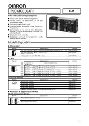
PER52 C24U 1C16C26R6U8 C28C 2U7R131C 3U6T1Y1U14JP3R25R15R15R15R10R10R105R21R5C 1U10R102 C12R7++U9R28C5R20R30RU10C3JP1C1+C17R14R1 R2R5R36R 1U1JP5 JP6RT4C2+ +C21R3R120R75R78R 14R35R702U12C35R 9C39R95C13CODE No.SI-NR 13R8TR1TR2C101R 1U13R 10R107R40R39R 5R56R57R54U15R96R95D6R94R97C20R6<strong>CIMR</strong>-<strong>F7</strong>Z<strong>Varispeed</strong> <strong>F7</strong>Frequency inverter for full flux vector control• Current Vector Control with or without PG• Torque Control• PID Control• Standard LCD operator• Fieldbus options: DeviceNet, Profibus, CANOpen• Stand still Autotuning• Powerful application oriented functionality• High slip braking• PLC Option card• Easy maintenance• Energy saving function• Standard RS485 communications - Modbus• CE, UL, and cUL marking• Customized application firmwareRatings• 200V Class three-phase 0.4 to 110KW• 400V Class three-phase 0.4 to 300 KWFrequency InvertersSystem ConfigurationSpecial Accessories3G3IV-PCN329-EInverter to PC cableSydrive ConfiguratorsoftwareJVOP-160-OYDigital Operator(LCD display)JVOP-161-OYDigital Operator(LED display)3G3IV-PCN126/326Digital OperatorExtension CableLine FilterRBraking AccessoriesST3G3RV-PFI@Input Noise FilterLKEB@ BrakingResistor UnitCDBR@BBraking UnitERF150WJ@Braking ResistorPower Supply<strong>Varispeed</strong> <strong>CIMR</strong>-<strong>F7</strong>Monitor Cards Encoder input Cards Communication CardsU17 736 0-C0210Reference Option CardsPLC Option Card<strong>Varispeed</strong> <strong>F7</strong>253
SpecificationsType Designation<strong>CIMR</strong> – <strong>F7</strong> Z 4 0P4 0Inverter<strong>F7</strong> seriesSpecificationsZ: European standardspecificationsVoltage2: 200 V class4: 400 V classProtective Enclosure0: Open chassis type (IP00)1: Enclosed type (IP20 / NEMA1)Max. Applicable Motor Output0P4: 0.4 kW~022: 22 kW~300: 300 kW"P" indicates a decimal[ point]200 V ClassModel <strong>CIMR</strong>-<strong>F7</strong>Zo 20P4 20P7 21P5 22P2 23P7 25P5 27P5 2011 2015 2018 2022 2030 2037 2045 2055 2075 2090 2110Max. apllicable motoroutput 1kW 0.55 0.75 1.5 2.2 3.7 5.5 7.5 11 15 18.5 22 30 37 45 55 75 90 110Inverter Capacity kVA 1.2 1.6 2.7 3.7 5.7 8.8 12 17 22 27 32 44 55 69 82 110 130 160OutputcharacteristicsPowerSupplyHarmonicWavePrevention1. Our standard 4-pole motors are used for max. applicable motor output. Choose the inverter model whose rated current is allowable within the motorrated current range.2. 322 A in case of Heavy duty mode3. When using the inverter of 200 V class 37 kW or more with a cooling fan of three-phase 230 V 50 Hz or 240 V 50/60 Hz power supply, a transformer forthe cooling fan is required.4. A 3-wired transformer is required at 12-pulse input.400 V ClassRated Current A 3.2 4.1 7.0 9.6 15 23 31 45 58 71 85 115 145 180 215 283 346 415 2Max. VoltageMax. output FrequencyRated Input Voltageand FrequencyAllowable VoltageFluctuationAllowable FrequencyFluctuation3-phase, 200/208/220/230/240 V (Proportional to input voltage)Heavy Duty (low carrier, constant torque applications): 150 Hz maxNormal Duty 1 or 2 (High/reduced carrier, variable torque applications): 400 Hz max3-phase 200/208/220/230/240 V, 50/60 Hz 3+10%, -15%DC Reactor Option Provided12-Pulse Input Not available Available 4Model <strong>CIMR</strong>-<strong>F7</strong>Zo 40P4 40P7 41P5 42P2 43P7 44P0 45P5 47P5 4011 4015 4018 4022 4030 4037 4045 4055 4075 4090 4110 4132 4160 4185 4220 4300Max. apllicable motoroutput 1kW 0.55 0.75 1.5 2.2 3.7 4.0 5.5 7.5 11 15 18.5 22 30 37 45 55 75 90 110 132 160 185 220 300Inverter Capacity kVA 1.4 1.6 2.8 4.0 5.8 6.6 9.5 13 18 24 30 34 46 57 69 85 110 140 160 200 230 280 390 510OutputcharacteristicsPowerSupplyHarmonicWavePreventionRated Current A 1.8 2.1 3.7 5.3 7.6 8.7 12.5 17 24 31 39 45 60 75 91 112 150 180 216 260 304 370 506 2 675 3Max. VoltageMax. output FrequencyRated Input Voltageand FrequencyAllowable VoltageFluctuationAllowable FrequencyFluctuation1. Our standard 4-pole motors are used for max. applicable motor output. Choose the inverter model whose rated current is allowable within the motor ratedcurrent range.2. 405 A in case of Heavy duty mode3. 540 A in case of Heavy duty mode4. A 3-wired transformer is required at 12-pulse input.±5%3-phase, 380/400/415/440/460/480 V (Proportional to input voltage)Heavy Duty (low carrier, constant torque applications): 150 Hz maxNormal Duty 1 or 2 (High/reduced carrier, variable torque applications): 400 Hz max3-phase 380/400/415/440/460/480 V, 50/60 Hz+10%, -15%DC Reactor Option Provided12-Pulse Input Not available Available 4±5%254Frequency Inverters
Enclosures200V ClassFrequency Inverters400V ClassModel <strong>CIMR</strong>-<strong>F7</strong>Z 20P4 20P7 21P5 22P2 23P7 25P5 27P5 2011 2015 2018 2022 2030 2037 2045 2055 2075 2090 2110Enclosed TypeNot(IEC IP20)Available as standardAvailable for optionavailableOpen Chassis Type(IEC IP00)Available by removing the upper and lower cover ofenclosed typeAvailable as standardModel <strong>CIMR</strong>-<strong>F7</strong>Z 40P4 40P7 41P5 42P2 43P7 45P5 47P5 4011 4015 4018 4022 4030 4037 4045 4055 4075 4090 4110 4132 4160 4185 4220 4300Enclosed Type(IEC IP20)Available as standard Available for option Not availableOpen Chassis Type(IEC IP00)Available by removing the upper and lower cover ofenclosed typeAvailable as standard<strong>Varispeed</strong> <strong>F7</strong>255
Common SpecificationsControl characteristicsProtective functionsEnvironmentModel Number<strong>CIMR</strong>-<strong>F7</strong>ZSpecificationControl method Sine wave PWM Closed Loop Vector control, Open Loop Vector control, V/f control, V/f with PG controlTorque characteristicsHeavy Duty (low carrier, constant torque applications): 2 kHz carrier frequency, 150% overload for 1 minute,higher carrier frequency possible with current derating.Normal Duty 1 (high carrier, variable torque applications): maximum carrier frequency, depending on inverter capacity,120% overload for 1 minute.Normal Duty 2 (variable torque applications): carrier frequency reduced, continuous overload capability increasedSpeed control range1:40 (V/f control)1:100 (Open Loop Vector control)1:1000 (Closed Loop Vector control)Speed control accuracy± 3% (V/f control)± 0.03% (V/f control with PG)± 0.2% (Open Loop Vector control)± 0.02% (Closed Loop Vector control)(25°C ± 10°C)Speed control response5 Hz (control without PG)30 Hz (control with PG)Torque limitsProvided (4 quadrant steps can be changed by constant settings.) (Vector control)Torque accuracy ± 5%Frequency range 0.01 to 150 Hz (Heavy Duty), 0.01 to 400 Hz (Normal Duty 1 or 2)Frequency accuracy (temperaturecharacteristics)Frequency setting resolutionOutput frequency resolutionOverload capacity andmaximum currentDigital references: ± 0.01% (-10°C to +40°C)Analog references: ± 0.1% (25°C ±10°C)Digital references: 0.01 HzAnalog references: 0.025/50 Hz (11 bits plus sign)0.01 HzHeavy Duty (low carrier, constant torque applications): 150% of rated output current for 1 minuteNormal Duty 1 or 2 (high/reduced carrier, variable torque applications): 120% of rated output current for 1 minuteFrequency setting signal0 to +10V, –10 to +10 V, 4 to 20 mA, pulse trainAccel/Decel time0.01 to 6000.0 s (4 selectable combinations of independent acceleration and deceleration time settings)Braking torqueApproximately 20% (Approximately 125% with Braking Resistor option,braking transistor built into Inverters of 18.5 kW or less)Main control functions Restarting after momentary power loss, speed search, overtorque/undertorque detection, torque limits, 17-speed control (maximum),4 acceleration and deceleration times, S-curve acceleration/deceleration, 3-wire control, auto-tuning (rotational or stationary), dwellfunction, cooling fan ON/OFF control, slip compensation, torque compensation, auto-restart after fault, jump frequencies, upper andlower limits for frequency references, DC braking for starting and stopping, high-slip braking, advanced PID control, energy-savingcontrol, MEMOBUS communications (RS-485/422, 19.2 kbps maximum), 2 motor parameter sets, fault reset and parameter copy function.Motor protectionProtection by electronic thermal overload relay.Instantaneous overcurrentStops at approx. 200% of rated output current.protectionFuse blown protectionStops for fuse blown.Overload protectionHeavy Duty (low carrier, constant torque applications): 150% of rated output current for 1 minuteNormal Duty 1 (high carrier, variable torque applications): 120% of rated output current for 1 minuteNormal Duty 2 (high carrier, variable torque applications): 120% of rated output current for 1 minute,increased continuous output current.Overvoltage protection 200 Class Inverter: Stops when main-circuit DC voltage is above 410 V.400 Class Inverter: Stops when main-circuit DC voltage is above 820 V.Undervoltage protection 200 Class Inverter: Stops when main-circuit DC voltage is below 190 V.400 Class Inverter: Stops when main-circuit DC voltage is below 380 V.Momentary power loss rideBy selecting the momentary power loss method, operation can be continued if power is restored within 2 s.throughCooling fin overheatingProtection by thermistor.Stall preventionStall prevention during acceleration, deceleration and running independently.Grounding protectionProtection by electronic circuits.Charge indicatorGlows when the main circuit DC voltage is approx. 10 VDC or more.Ambient operating-10°C to 40°C (Enclosed wall-mounted type)temperature–10°C to 45°C (Open chassis type)Ambient operating humidity95% max. (with no condensation)Storage temperature- 20°C to + 60°C (short-term temperature during transportation)Application siteIndoor (no corrosive gas, dust, etc.)Altitude1000 m max.Vibration10 to 20 Hz, 9.8 m/s 2 max.; 20 to 50 Hz, 2 m/s 2 max256Frequency Inverters
DimensionsOpen Chassis Type (IEC IP00)W1 4-dH1HVoltage200 V Class (3-phase)400 V Class (3-phase)Max. Applicable Motor Output InverterkW<strong>CIMR</strong>-<strong>F7</strong>Z Fig Dimensions in mm Approx. MassW H D W1 H1 H2 D1 T1 d kg0.4 ------0.75 ------1.5 ------2.2 ------3.7 ------5.5 ------7.5 ------11 ------15 ------Not available please use the IP20 type removing the upper and lower cover18.5 ------22 2022 0250 400195 385M6 212587.5 100 2.330 2030 0 275 450 220 435 2437 2037 029810057375 600250 57545 2045 0 32863112.53.2 M1055 2055 086450 725 348 325 70013075 2075 0 8790 2090 0 500 850 358 370 82010815 4.5 M12110 2110 0 575 885 378 445 855 140 1500.4 ------0.75 ------1.5 ------2.2 ------4.0 ------5.5 ------7.5 ------11 ------15 ------18.5 ------(5)WH2(5)Fig 1(5)Not available please use the IP20 type removing the upper and lower cover22 4022 030 4030 0275 450 258 220 4351002137 4037 07.52.3 M645 4045 0325 550 283 260 535 105 3655 4055 075 4075 088450 725 348 325 700 12.53.2 M1090 4090 0 189130110 4110 015102500 850 358 370 820132 4132 0 120160 4160 0 575 916 378 445 855 45.8 140 1604.5 M12185 4185 0260710 1305 413 540 1270220 4220 0 15 125.5280300 4300 0 916 1475 413 730 1440 405DT1D1CoolingMethodFancooledFanCooledFrequency Inverters<strong>Varispeed</strong> <strong>F7</strong>257
Enclosed Type (IEC IP20)<strong>F7</strong>Z 20P41 to <strong>F7</strong>Z25P51<strong>F7</strong>Z 27P51 to <strong>F7</strong>Z20181<strong>F7</strong>Z40P41 to <strong>F7</strong>Z45P51<strong>F7</strong>Z47P51 to <strong>F7</strong>Z40181W14-d 4-d<strong>F7</strong>Z 20221 to <strong>F7</strong>Z20751<strong>F7</strong>Z40221 to <strong>F7</strong>Z41601W1 4-dWH1H2H04 H3D1DT1W1WH2H1H3H04H3DT1D1(5)WH2H1(5)H3 H0H10H(5)DT1D1Fig 1 Fig 2Fig 3Voltage200 V Class (3-phase)400 V Class (3-phase)Max. Applicable Motor Output InverterkW<strong>CIMR</strong>-<strong>F7</strong>Z Fig Dimensions in mm Approx. MassW H D W1 H0 H1 H2 H3 D1 T1 d kg0.4 20P4 10.75 20P7 11573931.5 21P5 11 140 280 126 280 266 7 ---5 M52.2 22P2 13.7 23P7 1177 59 45.5 25P5 17.5 27P5 130006200 197 186 300 285 865.511 2011 1 310 10 7215 2015 13500240 207 216 350 33578 2.3 M6 1118.5 2018 1 380 307.522 2022 1254 535 195 400 385 1352425830 2030 1 279 615 220 450 435 165 1002737 2037 1298623 380 809 250 600 57520945 2045 1 3286812.53.2 M1055 2055 113094453 1027 348 325 725 700 30275 2075 1 950.4 40P4 10.75 40P7 11.5 41P5 12.2 42P2 13.7 43P7 14.0 44P0 15.5 45P5 17.5 47P5 111 4011 115 4015 118.5 4018 122 4022 130 4030 11 140 2802157126 280 266 7 ---395 M5177 59 4200 300 197 186 300 285 8240 350 207 216 350 335275 535 258 220 450 4357.5---8565.578 102.3 M6100 2437 4037 145 4045 1325 715 283 260 550 535 105 4010555 4055 1375 4075 196453 1027 348 325 725 700 12.5 3023.2 M1090 4090 1 97130110 4110 1122504 1243 358 370 850 820 15 393132 4132 1 4.5 M12 130160 4160 1 579 1324 378 445 918 855 45.8 408 140 17036CoolingMethodSelfcooledFancooledSelfCooledFancooled258Frequency Inverters
InstallationStandard ConnectionsDC reactor to improve inputpower factor (optional)UXBraking resistor unit (optional)Short-circuit barMain contactorT1 2 B1 B2L13-phase power380 to 480 V L250/60 Hz L3PEMulti-functiondigital inputs[Factory setting]FusesForward Run/StopReverse Run/StopExternal faultFault resetMulti-step speed setting 1Multi-step speed setting 2Jog frequency selectionLineFilterR/L1S/L2T/L3S1S2S3S4S5S6S7SNSCSP24V<strong>Varispeed</strong> <strong>F7</strong><strong>CIMR</strong>-<strong>F7</strong>Z47P5U/T1V/T2W/T3MAMBMCM1M2M3M4M5M6Fault contact output250 VAC, 1A max.30 VDC, 1A max.Contact output 1[Default : Running]Contact output 2[Default : Zero speed]Contact output 3[Default :Frequency agree 1]MMulti-function digitaloutput250 VAC, 1A max.30 VDC, 1A max.Frequency InvertersE(G)ShieldterminalShieldterminalE(G)2k ΩAnalog input settingadjustment3210 to 10V4 to 20mA2k ΩPPRP Pulse train input [Default:Frequency reference input]0 to 32kHz+VAnalog input power supply+15V, 20mAA1 Analog input 1: Masterfrequency reference0 to +10V (20 k Ω)Multi-function analog input 2A2[Default: Frequency bias4 to 20mA (250 Ω )]ACMPACFMAMACPulse train output0 to 32kHz (2.2 k Ω)[Default: Output frequency]Adjustment,20 k Ω+ -FMAdjustment,20 k Ω+ -AMMulti-function analog output 1(-10 to +10V 2mA / 4 to 20mA)[Default: Output frequency 0 to +10V]Multi-function analog output 2(-10 to +10V 2mA / 4 to 20mA)[Default: Output current 0 to +10V]0V-VAnalog input power supply-15V, 20mAMEMOBUScommunicationRS-485/422PPR+R-S+S-TerminatingresistanceIGShielded wiresPTwisted-pairShielded wires<strong>Varispeed</strong> <strong>F7</strong>259
Main CircuitVoltage 200 V 400 VModel <strong>CIMR</strong>-<strong>F7</strong>Z 20P4 to 2018 2022, 2030 2037 to 2110 40P4 to 4018 4022 to 4055 4075 to 4300Max. Applicable Motor Output 0.4 to 18.5 kW 22 to 30 kW 37 to 110 kW 0.4 to 18.5 kW 22 to 55 kW 75 to 300 kWR/L1S/L2T/L3R1/L11S1/L21T1/L31U/T1V/T2W/T3B1B2Main circuit inputpower supplyMain circuit inputpower supplyMain circuit inputpower supplyR-R1, S-S1 and T-T1 have been wired before--- shipment (See P59).---Brakingresistor unit•DC reactor( 1- 2)•DC power supply 1( 1 - )Inverter output------ Brakingresistor unit•DC power supply( 1- 2) 1•Braking unit( 3 - )•DC reactor( 1- 2)•DC power supply 1( 1 - )1. 1 - DC power input does not conform to UL/c-UL listed standard.2. Cooling fan power supply r/l 1 - /l 2 : 200 to 220 VAC 50 Hz, 200 to 230 VAC 60 Hz(A transformer is required for 230 V 50 Hz or 240 V 50/60 Hz power supply.)3. Cooling fan power supply r/l 1 - 200 / l 2 200: 200 to 220 VAC 50 Hz, 200 to 230 VAC 60 Hz, r/l 1 - 400 / l 2 400: 380 to 480 VAC 50/60 HzMain circuit inputpower supplyR-R1, S-S1 and T-T1 have been wired beforeshipmentInverter output------•DC power supply( 1- 2) 1•Braking unit( 3 - )123 --- ---/l 2r/l 1------ Cooling fan powersupply 2---200 / l 2 200 ---------400 / l 2 400Ground terminal (100 Ω or less)Ground terminal (10 Ω or less)Cooling fan powersupply 3Main circuit configuration<strong>CIMR</strong>-<strong>F7</strong>Z20P4 to 2018 <strong>CIMR</strong>-<strong>F7</strong>Z2022, 2030 <strong>CIMR</strong>-<strong>F7</strong>Z2037 to 2110200V Class<strong>CIMR</strong>-<strong>F7</strong>Z40P4 to 4018 <strong>CIMR</strong>-<strong>F7</strong>Z4022 to 4055 <strong>CIMR</strong>-<strong>F7</strong>Z4075 to 4300400V Class260Frequency Inverters
Control CircuitType No. Signal Name Function Signal LevelS1 Forward run/stop command Forward run when ON; stopped when OFF. 24 VDC, 8 mAS2 Reverse run/stop command Reverse run when ON; stopped when OFF.PhotocouplerS3 External fault input *1 Fault when ON. Functions are selected byS4 Fault reset *1 Reset when ONsetting H1-01 to H1-05.S5 Multi-step speed reference 1 *1 (Master/ Auxiliary frequency reference whenauxiliary switch)ON.S6 Multi-step speed reference 2 *1 Multi-step setting 2 when ON.S7 Jog frequency reference*1 Jog frequency when ON.SC Digital input common – –SN Digital Input Neutral – –SP Digital Input Power Supply +24VDC power supply for digital inputs 24 VDC, 250 mA max. *2+V 15 V power output 15 V power supply for analog references 15 V(Max. current: 20 mA)–V –15 V power output –15 V power supply for analog references –15 V(Max. current: 20 mA)A1 Frequency reference –10 to +10 V/100% –10 to +10 V(20 kΩ)Digital input signalsAnalog input signalsSequence output signalsAnalog outputsignalsPulse I/ORS-485/422A2 Multi-function analog input 4 to 20 mA/100%–10 V to +10 V/100%Function is selected bysetting H3-09.4 to 20 mA(250Ω)–10 V to +10 V(20kΩ)AC Analog reference common – –E(G) Shield wire, optional ground lineconnection point– –M1 Running signalOperating when ON.Multi-functionRelay contacts(1NO contact)contact outputs Contact capacity:M21 A max. at 250 VAC1 A max. at 30 VDC *3M3 Zero speed Zero level (b2-01) or below when ONM4M5 Speed agreement detection Within ±2 Hz of set frequency whenM6ON.MAMBFault output signal Fault when CLOSED across MA and MCFault when OPEN across MB and MCMCFMMulti-function analog output (frequencyoutput)AC Analog common –AM Multi-function analog output(current monitor)0 to 10 V, 10V=100% output frequency0 to 10 V, 10V=200% Inverter's ratedcurrentMulti-function analog output1Multi-function analog output2Relay contactsContact capacity:1 A max. at 250 VAC1 A max. at 30 VDC *3–10 to +10 V max. ±5%2 mA max.4 to 20 mA current outputRP Pulse input *4 H6-01 (Frequency reference input) 0 to 32 kHz (3 kΩ)High level voltage 3.5 to 13.2VMP Pulse monitor H6-06 (Output frequency) 0 to 32 kHz+15 V output (2.2 kΩ)R+ MEMOBUS communications input For 2-wire RS-485, short R+ and S+ as well as R- and S-. Differential input,R-Photocoupler isolationS+ MEMOBUS communicationsDifferential input,S- outputPhotocoupler isolationIG Signal common – –Frequency Inverters* 1. The default settings are given for terminals S3 to S7. For a 3-wire sequence, the default settings are a 3-wire sequence for S5, multi-step speed setting1 for S6 and multi-step speed setting 2 for S7.* 2. Do not use this power supply for supplying any external equipment.* 3. When driving a reactive load, such as a relay coil with DC power supply, always insert a flywheel diode* 4. Pulse input specifications are given in the following tableLow level voltage 0.0 to 0.8 VHigh level voltage 3.5 to 13.2 VH duty 30% to 70%Pulse frequency 0 to 32 kHz<strong>Varispeed</strong> <strong>F7</strong>261
Remove the upper and lower covers forthe models of 15 kW or less in 200 Vand 400 V classes.When using open chassis type inverters of 200 V/400 V22 kW or more, secure spaces for eyebolts and wiringof the main circuit.Internal HeatsinkUpper Cover55 ˚CUpper CoverUpper Part AirTemperature–10 to 55 ˚CHeatsink50 mm or more120 mm or moreAirHeatsinkOpen ChassisType InverterLower Cover45 ˚CInverter InletTemperature–10 to 45 ˚CPeripheralTemperature 40 ˚CLower CoverCover MTG Screw30 mm or more 30 mm50 mm or moreor moreSide Spaces120 mm or moreAirTop and Bottom SpacesInverter Heat Loss200 V ClassModel <strong>CIMR</strong>-<strong>F7</strong>Z 20P4 20P7 21P5 22P2 23P7 25P5 27P5 2011 2015 2018 2022 2030 2037 2045 2055 2075 2090 2110Inverter Capacity kVA 1.2 1.6 2.7 3.7 5.7 8.8 12 17 22 27 32 44 55 69 82 110 130 160Heat Loss WRated Current A 3.2 4.1 7.0 9.6 15 23 31 45 58 71 85 115 145 180 215 283 346 415400 V ClassFin W 20 27 50 70 112 164 219 374 429 501 586 865 1015 1266 1588 2019 2437 2733Inside Unit W 39 42 50 59 74 84 113 170 183 211 274 352 411 505 619 838 997 1242Total Heat Loss W 59 69 100 129 186 248 332 544 612 712 860 1217 1426 1771 2207 2857 3434 3975Fin Coding Self cooled Fan cooledModel <strong>CIMR</strong>-<strong>F7</strong>Z 40P4 40P7 41P5 42P2 43P7 44P0 45P5 47P5 4011 4015 4018 4022 4030 4037 4045 4055 4075 4090 4110 4132 4160 4185 4220 4300Inverter Capacity kVA 1.4 1.6 2.8 4.0 5.8 6.0 9.5 13 18 24 30 34 46 57 69 85 110 140 160 200 230 280 390 510Heat Loss WRated Current A 1.8 2.1 3.7 5.3 7.6 8.0 12.5 17 24 31 39 45 60 75 91 112 150 180 216 260 304 370 506 675Fin W 14 17 36 59 80 91 127 193 252 326 426 466 678 784 901 1203 1399 1614 2097 2388 2791 3237 3740 5838Inside Unit W 39 41 48 56 68 70 82 114 158 172 208 259 317 360 415 495 575 671 853 1002 1147 1372 1537 2320Total Heat Loss W 53 58 84 115 148 161 209 307 410 498 634 725 995 1144 1316 1698 1974 2285 2950 3390 3938 4609 5277 8158Fin Coding Self cooled Fan cooled262Frequency Inverters
AttachmentsHeatsink External Mounting AttachmentThe <strong>Varispeed</strong> <strong>F7</strong> inverters under the 200/400 V class 18.5 kW or less need this attachment for mounting the heatsink externally. This attachmentexpands the outer dimensions of the width and height of the inverter. (Attachment is not required for inverters of 22 kW or more.)H1HMounting PanelWallW1W D1 D2D3 or more<strong>CIMR</strong>-<strong>F7</strong>Z20P420P721P522P223P725P527P520112015201840P440P741P542P243P744P045P547P5401140154018AttachmentOrder CodeDimensions in mmW H W1 H1 D1 D2 D372616-EZZ08676A 155 302 126 290 122.637.4 4057.4 6072616-EZZ08676B 210 330 180 316 136.1 63.4 7072616-EZZ08676C 250 392 216 372 133.6 76.4 8572616-EZZ08676A 155 302 126 290 122.637.4 4057.4 6072616-EZZ08676B 210 330 180 316 136.1 63.4 7072616-EZZ08676C 250 392 216 372 133.6 76.4 85Frequency InvertersPanel Cut for External Mounting of Cooling Fin (Heatsink)4-d Tapa(W3)(W2)a4-d Tapa(W3)(W2)abAbW1AWFig 1W1WFig 2B2-5 Dia. HolesBaa(W2)(H2)a(W3)(W2)a(H2)(H3) H1(H3)(H3) (H2)(H2) (H3)H1(W3)HH(W3)4-d Tapaa(W2)AW1WFig 3B(W2)aa(H3) (59)(19) (H3)H1(W3)H<strong>CIMR</strong>-Dimensions in mmFig<strong>F7</strong>ZW H W1 (W2) (W3) H1 (H2) (H3) A B d20P420P721P522P2155 302 126 6 8.5 290 9.5 6 138 271 M523P725P5127P5210 330 180 6.5 316 9 7 197 29820118.52015250 392 216 8.5 372 9.5 10 233 353 M620182022250 400 195 385244 36924.5 3 8 7.52030 275 450 220 435 269 4192037375 600 250575 15 359 5452045254.5 812.52055450 725 325 700 13.5 434 6732075M102090 500 850 370 57 8 820 484 782 19 15 M122110 575 885 445 55 10 855 555 81740P440P741P542P243P7155 302 126 6 8.5 290 9.5 6 138 271 M544P0 145P547P5210 330 180 6.5 316 9 7 197 29840118.54015250 392 216 8.5 372 9.5 10 233 35340184022M6275 450 220 3 435269 4194030403724.58 7.54045325 550 260 8 535 309 5194055 240754090450 725 325 54.5 8 700 13.5 12.5 434 673 M1041104132500 850 370 57 8 820 19 15 484 782 M124160 3 575 925 445 55 10 895 1 15 555 8171.The sizes are different between the top and the bottom. Refer Fig 3<strong>Varispeed</strong> <strong>F7</strong>263
PER52 C24U 1C16C 2R131U7 C 3 U6T1U14R10R10Y1JP3R25R15R15R15R5C 1U10R21R102 C12R7++U9R28R20R30RU10C3JP1C1C17R14R1 R2R5R36R 1C2C21R3R1202U12C35R 9C5C13JP5 JP6RT4R105+U1+ +C39R75R78R 14R95R35R70CODE No.SI-NR 13R8TR1TR2C101R 1R 10R107R40R39R 5R57R54R56R96R95U13U15D6R94R97C20R6Ordering InformationType Name Description FunctionAO-08 / 3G3IV-PAO08Outputs analog signal for monitoring inverter output state (output freq., output current etc.) afterabsolute value conversion.• Output resolution: 8 bits (1/256)• Output voltage: 0 to {10 V (non isolated) EOutput channel: 2 channelsBCMonitor option cardFeedback Speed Control CardAO-12 / 3G3IV-PAO12DO-08 / 3G3IV-PDO08DO-02C / 3G3IV-PDO02CPG-A2 / 3G3FV-PPGA2PG-B2 / 3G3FV-PPGB2PG-D2 / 3G3FV-PPGD2Analog monitor cardDigital output card2C-relay output cardPG Speed Controller Card(Used for V/f control with PG orFlux Vector)Outputs analog signal for monitoring inverter output state (output freq., output current etc.)• Output resolution: 11 bits (1/2048) + code• Output voltage: |10 to {10 V (non isolated) EOutput channel: 2 channelsOutputs isolated type digital signal for monitoring inverter run state (alarm signal, zero speeddetection etc.) .Output channel: Photo coupler 6 channels (48 V, 50 mA or less)Relay contact output 2 channels(250 VAC, 1 A or less30 VDC, 1 A or less)• Two multi-function contact outputs (2C-relay) can be used other than those of the inverterproper unit.• Phase A pulse (single pulse) inputs (voltage, complementary, open collector input)• PG frequency range: Approx. 30 kHz max. [ Power supply output for PG: +12 V, max. current200 mA ]Pulse monitor output: +12 V, 20 mA• Phase A and B pulse inputs (exclusively for complementary input)• PG frequency range: Approx. 30 kHz max. [ Power supply output for PG: +12 V, Max. current200 mA]• Pulse monitor output: Open collector, +24 V, Max. current 30 mA• Phase A pulse (differential pulse) input for V/f control (RS-422 input)• PG frequency range: Approx. 300 kHz max. [ Power supply output for PG: +5 V or +12 V,Max. current 200 mA]• Pulse monitor output: RS-422Frequency InvertersPG-X2 / 3G3FV-PPGX2• Phase A, B and Z pulse (differential pulse) inputs (RS-422 input)• PG frequency range: Approx. 300 kHz max. [ Power supply output for PG: +5 V or +12 V,Max. current 200 mA]• Pulse monitor output: RS-422DEFCommunication option cardReference option cardPLC option3G3RV-PDRT2C26 R6 U8 C28SI-P1SI-S1SI-JU17 73600-C0210AI-14U / 3G3IV-PAI14UAI-14B / 3G3IV-PAI14BDI-08 / 3G3IV-PDI08DI-16H2 / 3G3IV-PDI16H23G3RV-P10ST8-EDeviceNet option cardProfibus-DP option cardCANopen option cardLONWORKS option cardAnalog input cardDigital reference cardPLC optionPLC option with DeviceNet• Used for running or stopping the inverter, setting or referencing parameters, and monitoringoutput frequency, output current, or similar items through DeviceNet communication with thehost controller.• Used for running or stopping the inverter, setting or referencing parameters, and monitoringoutput frequency, output current, or similar items through Profibus-DP communication withthe host controller.• Used for running or stopping the inverter, setting or referencing parameters, and monitoringoutput frequency, output current, or similar items through CANopen communication with thehost controller.• Used for HVAC control, running or stopping the inverter, setting or referencing parameters,and monitoring output current, watt-hours, or similar items through LONWORKS communicationswith peripheral devices.• 2 channel high resolution analog input card• Channel 1: 0 to 10 V (20KΩ)• Channel 2: 4 to 20 mA (250Ω)• Resolution 14 bit• 3 Channel high resolution analog input card• Signal level: -10 to +10V (20 KΩ)• 4 to 20 mA (250 Ω)•Resolution: 13 bit + sign• 8 bit digital speed reference input card• 16 bit digital speed reference input card• Full PLC featrues, wireless installation and seamless access to the inverter parameters andanalogue/digital inputs and outputs.• Embedded Compubus/S fieldbus• Standard <strong>Omron</strong> tools can be used for programming• Same features than standard model with DeviceNet support.3G3RV-P10ST8-DRT-E<strong>Varispeed</strong> <strong>F7</strong>265
G AccessoriesName Description InstallationJVOP-160-OY5 lines LCD digital operator7 Language supportPanel Cutout572-M3 MTG HolesPanelDigital operatorJVOP-161-OY12012011114.52.544ThroughHole207 segment LED digital operator70 7015.8 6.4(60)Panel Cutout installationAccessories3G3IV-PCN126Digital operator extension cable1 meters-----3G3IV-PCN3263 meters3G3IV-PCN329-E PC configuration cable -----Sysdrive Configurator Computer software Configuration and monitoring software toolUser’s manuyl YEG-TOE-S616-55.1-OY -----266Frequency Inverters
H Braking Unit, Braking Resistor UnitInverterBraking unitInverter-mounted Type (3 %ED, 10 secmax) 2Braking Resistor Unit 1Separately-installed Type (10 %ED, 10 sec. max.) 3Voltage200 VClass400 VClassMax.Applicable Motoroutput kWModel No. of ModelCDBR_ used ERF-150WJ_Model<strong>CIMR</strong>-<strong>F7</strong>Z_ResistanceNo. ofusedBrakingtorque %ModelLKEB_Specificationsof Resistor1. When connecting a mounting type resistor or braking resistor unit, set system constant L3-04 to 0 (stall prevention disabled during deceleration). If operatingwithout changing the constant, motor does not stop at set deceleration time.2. When connecting mounting type braking resistor, set system constant L8-01 to 1 (braking resistor protection enabled).3. Load factor during deceleration to stop a load with constant torque. With constant output or continuous regenerative braking, the load factor is smallerthan the specified value.4. Resistance value per one braking unit. Slect a resistance value that is larger than connectable minimum resistance value to obtain enough brakingtorque.5. For an application with large regenerative power such as hoisting, the braking torque or other items may exceed the capacity of a braking unit with abraking resistor in a standard combination (an result in capacity overload). Contact your <strong>Omron</strong> representatives when the braking torque or any otheritem exceeds the values in the table.No. ofusedBrakingtorque %ConnectableMin ResistanceValue Ω0.4 20P4201 200 Ω 1 220 20P7 70 W 200 Ω 1 220 480.75 20P7 201 200 Ω 1 125 20P7 70 W 200 Ω 1 125 481.5 21P5 101 100 Ω 1 125 21P5 260 W 100 Ω 1 125 482.2 22P2 700 70 Ω 1 120 22P2 260 W 70 Ω 1 120 163.7 23P7 620 62 Ω 1 100 23P7 390 W 40 Ω 1 125 16Built-in5.5 25P525P5 520 W 30 Ω 1 115 167.5 27P5 27P5 780 W 20 Ω 1 125 9.611 2011 2011 2400 W 13.6 Ω 1 125 9.615 2015 2015 3000 W 10 Ω 1 125 9.618.5 2018 2015 3000 W 10 Ω 1 125 9.622 2022 2022B 1 2022 4800 W 6.8 Ω 1 125 6.430 2030 2015B 2 --- ---2015 3000 W 10 Ω 2 125 9.637 2037 2015B 2 2015 3000 W 10 Ω 2 100 9.645 2045 2022B 2 2022 4800 W 6.8 Ω 2 120 6.455 2055 2022B 2 2022 4800 W 6.8 Ω 2 100 6.475 2075 2110B 1 2022 4800 W 6.8 Ω 3 110 1.690 2090 2110B 1 2022 4800 W 6.8 Ω 4 120 1.6110 2110 2110B 1 2018 4800 W 8 Ω 5 100 1.60.4 40P4751 750 Ω 1 230 40P7 70 W 750 Ω 1 230 960.75 40P7 751 750 Ω 1 130 40P7 70 W 750 Ω 1 130 961.5 41P5 401 400 Ω 1 125 41P5 260 W 400 Ω 1 125 642.2 42P2 301 300 Ω 1 115 42P2 260 W 250 Ω 1 135 643.7 43P74.0 44P0 Built in201 200 Ω 1 110 43P7 390 W 150 Ω 1 135 325.5 45P545P5 520 W 100 Ω 1 135 327.5 47P5 47P5 780 W 75 Ω 1 130 3211 4011 4011 1040 W 50 Ω 1 135 2015 4015 4015 1560 W 40 Ω 1 125 2018.5 4018 4018 4800 W 32 Ω 1 125 19.222 4022 4030B 1 4022 4800 W 27.2 Ω 1 125 19.230 4030 4030B 1 4030 6000 W 20 Ω 1 125 19.237 4037 4045B 1 4037 9600 W 16 Ω 1 125 12.845 4045 4045B 1 4045 9600 W 13.6 Ω 1 125 12.8--- ---55 4055 4030B 2 4030 6000 W 20 Ω 2 135 19.275 4075 4045B 2 4045 9600 W 13.6 Ω 2 145 12.890 4090 4220B 1 4030 6000 W 20 Ω 3 100 3.2110 4110 4220B 1 4030 6000 W 20 Ω 3 100 3.2132 4132 4220B 1 4045 9600 W 13.6 Ω 4 140 3.2160 4160 4220B 1 4045 9600 W 13.6 Ω 4 140 3.2185 4185 4220B 1 4045 9600 W 13.6 Ω 4 120 3.2220 4220 4220B 1 4037 9600 W 16 Ω 5 110 3.2300 4300 4220B 2 4045 9600 W 13.6 Ω 6 110 3.2Frequency Inverters<strong>Varispeed</strong> <strong>F7</strong>267
Connections for braking unitsConnections for braking resistors3-phasePowerSupplyMCCB<strong>Varispeed</strong> <strong>F7</strong>BrakingResistorMotorBraking Resistor OverloadRelay Trip Contact(Thermal Relay Trip Contact)BrakingResistorUnitBraking Resistor OverloadRelay Trip Contact(Thermal Relay Trip Contact)BrakingResistorUnit * 3· Set constant L8-01 to 1(mounting type brakingresistor protectionenabled).· Set sequence to shutt offthe power side at inverterfault contact output.<strong>Varispeed</strong> <strong>F7</strong>Level DetectorBraking Unit 1Cooling Fin Overheat Contact(Thermoswitch Contact)Braking Unit 2* 2Cooling Fin Overheat Contact(Thermoswitch Contact)Braking UnitModel CDBR-2015 B, -2022 B, -4030B, -4045 BModel CDBR-2110 B30 ormore4-M4 MTG Holes 7238 381281403-lead Wire Inlet(20 Dia. Rubber Bush)138150114.530 ormore 138.566.5100 or more100 or more1236.53703503177330ormore100140Main CircuitTerminalM659 5014018030ormore4-M6MTG Holes104111156200100 or less 100 or lessLead Wire Inlet(28 Dia. Rubber Bush)2-lead Wire Inlet(35 Dia. Rubber Bush)Mass 1.8 KgMass 8.5 KgModel CDBR-4220 B936.53703553177030ormore156.5210Main CircuitTerminalM6118.5 5021030or4-M6MTG Holes250 more200104111156100 or more 100 or moreLead Wire Inlet(28 Dia. Rubber Bush)2-lead Wire Inlet(35 Dia. Rubber Bush)Mass 12 KgBraking Resistor Unit (Inverter-mounted Type)Mass: 0.2 kgModel ERF-150WJ_Note: Prepare mounting screws(2-M4x8 tapped screws).Screws 8mm or more and generalmetric screws cannot be used.268Frequency Inverters
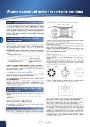
Braking Resistor Unit (Separately-installed Type)C30 or more A30 or moreMTG ScrewDB150150 or more 150 or moreMTG ScrewC50 or more A50 or moreDB260200 or more 200 or moreVoltage220 VClass400 VClassModelLKEB-_Dimensions in mmMasskgA B C D MTG Screw20P7 105 275 50 260 M5 x 3 3.021P5 130 350 75 335 M5 x 4 4.522P2 130 350 75 335 M5 x 4 4.523P7 130 350 75 335 M5 x 4 5.025P5 250 350 200 335 M6 x 4 7.525P5 250 350 200 335 M6 x 4 8.540P7 105 275 50 260 M5 x 3 3.041P5 130 350 75 335 M5 x 4 4.542P2 130 350 75 335 M5 x 4 4.543P7 130 350 75 335 M5 x 4 5.045P5 250 350 200 332 M6 x 4 7.547P5 250 350 200 332 M6 x 4 8.5Voltage220 VClass400 VClassModelDimensions in mmMassLKEB-_ A B C D MTG Screw kg2011 266 543 246 340 M8 x 4 102015 356 543 336 340 M8 x 4 152018 446 543 426 340 M8 x 4 192022 446 543 426 340 M8 x 4 194011 350 412 330 325 M6 x 4 164015 350 412 330 325 M6 x 4 184018 446 543 426 340 M8 x 4 194022 446 543 426 340 M8 x 4 194030 356 956 336 740 M8 x 4 254037 446 956 426 740 M8 x 4 334045 446 956 426 740 M8 x 4 33Frequency InvertersAC ReactorConnection ExampleApplication ExampleMCCBAC reactor<strong>Varispeed</strong> <strong>F7</strong>MotorPower supplycapacity (kVA)AC Reactor required forpower supply harmonicsAC Reactornot requiredInverter capacity (kVA)200 V Class 400 V ClassMax. Applicable Current Value Inductance Code No. Max. Applicable Current Value Inductance Code No.Motor Output kW AmHMotor Output kW AmH0.4 2.5 4.2 X 002553 0.4 1.3 18.0 X 0025610.75 5 2.1 X 002554 0.75 2.5 8.4 X 0025621.5 10 1.1 X 002489 1.5 5 4.2 X 0025632.2 15 0.71 X 002490 2.2 7.5 3.6 X 0025643.7 20 0.53 X 002491 3.7 10 2.2 X 0025005.5 30 0.35 X 002492 5.5 15 1.42 X 0025017.5 40 0.265 X 002493 7.5 20 1.06 X 00250211 60 0.18 X 002495 11 30 0.7 X 00250315 80 0.13 X 002497 15 40 0.53 X 00250418.5 90 0.12 X 002498 18.5 50 0.42 X 00250522 120 0.09 X 002555 22 60 0.36 X 00250630 160 0.07 X 002556 30 80 0.26 X 00250837 200 0.05 X 002557 37 90 0.24 X 00250945 240 0.044 X 002558 45 120 0.18 X 00256655 280 0.038 X 002559 55 150 0.15 X 00256775 360 0.026 X 002560 75 200 0.11 X 00256890 500 0.02 X 010145 90/110 250 0.09 X 002569110 500 0.02 X 010145 132/160 330 0.06 X 002570185220490 0.04 X 002690300 660 0.03 X 002691<strong>Varispeed</strong> <strong>F7</strong>269
DC ReactorDC ReactorMCCBTake off thecommon barbetween G1and G2, andwire as shownin the diagram.⊕⊕<strong>Varispeed</strong> <strong>F7</strong>MotorPowerSupplyCapacity(kVA)With Reactor forPower SupplyCoordinationWithout ReactorInverter Capacity (kVA)Max. ApplicableMotor Output kW0.4200 V Class 400 V ClassCurrent ValueAInductancemHCode No.Max. ApplicableMotor Output kWCurrent ValueAFuse installationTo protect the inverter, it is recommended to use semiconductor fuses like they are shown in the table belowInductancemHCode No.0.45.4 8 X0100480.75 0.753.2 28 X0100521.51.52.2 18 3 X0100492.25.7 11 X0100533.7 3.7 12 6.3 X0100545.55.536 1 X0100507.5 7.523 3.6 X010055111172 0.5 X01005133 1.9 X01005615 1518.5 90 0.4 X010176 18.5 47 1.3 X01017722 to 110 Built-in 22 to 300 Built-inInverter TypeFUSEVoltage (V) Current (A) I 2 t (A 2 s)20P4 240 10 12~2520P7 240 10 12~2521P5 240 15 23~5522P2 240 20 34~9823P7 240 30 82~22025P5 240 40 220~61027P5 240 60 290~13002011 240 80 450~50002015 240 100 1200~72002018 240 130 1800~72002022 240 150 870~162002030 240 180 1500~230002037 240 240 2100~190002045 240 300 2700~550002055 240 350 4000~550002075 240 450 7100~640002090 240 550 11000~640002110 240 600 13000~83000Inverter TypeFUSEVoltage (V) Current (A) I 2 t (A 2 s)40P4 480 5 6~5540P7 480 5 6~5541P5 480 10 10~5542P2 480 10 18~5543P7 480 15 34~7244P0 480 20 50~57045P5 480 25 100~57047P5 480 30 100~6404011 480 50 150~13004015 480 60 400~18004018 480 70 700~41004022 480 80 240~58004030 480 100 500~58004037 480 125 750~58004045 480 150 920~130004055 480 150 1500~130004075 480 250 3000~550004090 480 300 3800~550004110 480 350 5400~230004132 480 400 7900~640004160 480 450 14000~2500004185 480 600 20000~2500004220 480 700 34000~4000004300 480 900 52000~920000ALL DIMENSIONS SHOWN ARE IN MILLIMETERS.To convert millimeters into inches, multiply by 0.03937. To convert grams into ounces, multiply by 0.03527.Cat. No. I23E-EN-01In the interest of product improvement, specifications are subject to change without notice.270Frequency Inverters