
Create successful ePaper yourself
Turn your PDF publications into a flip-book with our unique Google optimized e-Paper software.
STANDARD MACHINE ELEMENTS<strong>Catalogue</strong> <strong>14.0</strong>
®ContentsStandard Parts for Clamping and OperatingProduct range ............................................ 2Machine and Fixture ElementsProduct range ............................................ 4IntroductionThe Company ............................................ 6GANTER-Standard Machine Elements on DVD ................... 8GANTER-Standard Machine Elements in the Internet .............. 9Product FamilyStainless Steel .......................................... 10Table of contentsProduct overviews. ....................................... 12Alphabetical index ....................................... 901Numericalindex ........................................ 909AnnexTechnicalInformation, Tables. .............................. 881Otto <strong>Ganter</strong> GmbH & Co. KGNormteilefabrikTriberger Strasse 3D-78120 FurtwangenGermanyPhone +49 7723 6507-0Fax +49 7723 4659E-Mailinfo@ganter-griff.deInternet www.ganter-griff.com1
®Standard Parts for Clamping and Operating1.1HandlesKnobsPage 491.2Cabinet ªUº handlesTubular handlesPage 891.3Cranked handlesPage 1471.4HandwheelsPage 1611.5Adjustablehand leversPage 2011.6Clamping leversTension leversPage 2512
1.7Star knobs, Wing screwsKnurled screwsPage 2771.8Control knobsIndexing mechanismsPage 3371.11.9Position indicatorsPage 3751.21.31.41.51.61.71.81.93
®Machine and Fixture elements2.1Indexing plungersSpring plungers, Ball lock pinsPage 3912.2Screws, NutsWashersPage 4712.3Clamping bolts, Eccentrical camsShaft clamping unitsPage 5532.4Toggle clamps, Power clampsHook clampsPage 5732.5Levelling feetDoor locks, HingesPage 6812.6Oil level sight glassesPlugsPage 7374
2.7Universal joints2.8Fork joints, Ball jointsPage 761Tube clamp connectorsLinear actuatorsPage 7952.12.22.32.42.52.62.72.85
®GANTER-Standard Machine Elements
The CompanyEstablished in 1894, our medium-sized family-owned business has forover 100 years manufactured standard parts for every branch of industryat home and abroad.The Product RangeMany decades of experience have made us the leading supplier ofstandard operating and clamping parts and of fixture and machine elements.Our claim is backed by the scope and quality of our product offer.OTTO GANTER GmbH & Co. KGBerger Tools Ltd. UKELESA S.p.A - MONZA - (MILAN) - ITALYWith the publication of this catalogue, all previousissues become invalid. Technical detailsare subject to change without notice. The detailsgiven herein comply with state of the artengineering at the time of printing. We reservethe right to amend errors and to remove individualarticles from the product assortment.The products listed in this catalogue havebeen developed as standard products withthe aim of covering the widest possible spectrumof requirements. We cannot be heldliable and responsible for special applicationsinvolving extraordinary or unusual uses orrequirements concerning our products. Ourdesign department will be pleased to answerquestions on certain product properties suchas missing tolerance, dimensional details orstrength classes.All rights in the catalogue are held byOtto <strong>Ganter</strong> GmbH & Co. KG. Reprints, alsoin extracts, are not permitted.OTTO GANTER GmbH & Co. KGJune 2008The ServiceThe goods we hold in stock are customer driven:We normally deliver ex stock.Meeting specific customer requirements is an essentialelement ofour business policy.Rely on our experience, adaptability and modern production processes.The <strong>Catalogue</strong>Our GANTER catalogue is our showpiece display cabinet. Designedboth as a loose-leaf compendium of standard parts and a referencebook, its clear and user-friendly structure has set standards for manyyears.Besides the print version, the catalogue is also available on DVD andin the Internet, with CAD capable product drawings in 2D and 3D.Berger Tools Ltd.A wealth of UK engineering market knowledge, built up over 25 yearsmakes Berger Tools Ltd. a key single source supplier of all manufacturingconsumables. We are ISO 9001:2000 accredited and have acquireda reputation as a reliable and competitive supplier. As a ªfamily runºbusiness we understand the importance of excellent customer service.Our aim is to taylor our services to meet your procurement needs, andultimately be your single source for standard machine elements.ELESA Ò -StandardsFor 35 years ELESA products have accounted for an essentialpart ofthe GANTER product range.ELESA standards include an exclusive offer of operating and machineelements made of plastic ± unique in range, quality and design. 60years of experience in processing plastic materials have made ELESAthe market leader world-wide.It is plastic operating elements, in particular, which are available onthe market in very different quality levels.ELESA products are the result of a corporate philosophy which seesultimate quality standards as a manifestation of competence and commitmentto the customer.7
®GANTER-Standard Parts on DVDSelect, design and orderThe GANTER product range is also available on DVDas digital product catalogue.Working with the DVD is a quick, convenient and easy wayto access the whole product assortment.The interactive article selection provides all important productinformation items:Outline drawings with dimensional tables · Design · Photo ·Article number · RoHS conformity · Weight · Productdrawings in 2D (DXF) and 3D (IGES) · <strong>Catalogue</strong> pages inPDF format.After placing the DVD in the drive, the catalogue will start automatically.8
®GANTER-Standard Parts in the Internetwww.ganter-griff.com...amouse click awayThe GANTER product range is also available online atwww.ganter-griff.com ± always up to datewith the latest products.Various practicalselection procedures combined with the optionsof the Internet technology take you quickly to the productyou are looking for.Use the Quickfinder with its interactive selection to take youto the desired design or article number. Information on RoHSconformity is also given.The next steps are:Placing your selection in the shopping basket for enquiries ororders, downloading product drawings in 2D (DXF) and in allstandard 3D formats.CAD capable product drawings of the GANTER standardparts can also be downloaded free of charge via the CADportals www.partserver.com or www.traceparts.com9
®Product Family: Stainless Steel
The GANTER product range offers an extraordinary wealth ofstandard products made of Stainless Steel, meeting the rising demandfor reasonably priced Stainless Steel components.The use of Stainless Steel, rustfree material is prescribed by law inmany industries, particularly in the food and chemical industry andfor use in ªaggressiveº ambient conditions.Stainless Steel is often used in place of surface electro-plating. Italso avoids potentially hazardous and ecologically damaging processesand methods and uncontrollable dimensional changes causedby the materialplating.The chapter ªTechnicalInformationº on page 881 summarises themost important properties of the Stainless Steel grades used in theGANTER product range.11
®Handles, KnobsGN 798RevolvinghandlesTechnopolymer,Aluminium,SteelPage 50GN 798.1RevolvinghandlesTechnopolymer/Stainless SteelGN 598.5RetractablehandlesDuroplast/Stainless SteelPage 59GN 598.7Retractablesafety handlesDuroplast/SteelDIN 319Ball knobsSteel,Aluminium,Stainless SteelPage 67DIN 319Ball knobsDuroplastPress on typePage 51GN 798.3RetractablehandlesTechnopolymer/SteelPage 52GN 798.5RetractablehandlesTechnopolymer/Stainless SteelPage 53GN 598RevolvinghandlesDuroplast/SteelPage 60GN 599.5RevolvingcylindricalhandlesTechnopolymer/Stainless SteelPage 61DIN 98RevolvinghandlesSteel,Aluminium,TechnopolymerPage 62DIN 39Fixed handlesSteel,TechnopolymerPage 68I.622ELESA-Domedgear knobTechnopolymerPage 70GN 519CylindricalknobsDuroplastPage 72GN 519.1CylindricalknobsTechnopolymerPress on typePage 56GN 598.1RevolvinghandlesDuroplast/Stainless SteelPage 63GN 319.2Revolvingball knobsDuroplast/SteelPage 73GN 201Ellipticalshaped knobsDuroplastPage 57GN 598.3RetractablehandlesDuroplast/SteelPage 64DIN 319Ball knobsDuroplast,TechnopolymerPage 74GN 419Taper knobsDuroplastPage 58Page 66Page 7512Stainless Steel
1.1GN 310Gear leverhandlesDuroplast/SteelGN 676.1KnobsSteelPage 76GN 310Gear leverhandlesDuroplast/Stainless SteelPage 85GN 676.5KnobsStainless SteelPage 77GN 563.2T-HandlesAluminiumPage 85GN75Waist shapedknobsSteelPage 78L.652ELESA-T-HandlesTechnopolymerPage 86GN75Waist shapedknobsSteelPage 80L.652 pELESA-T-HandlesTechnopolymerThreaded shaftSteelPage 81EKKELESA-KnobsTechnopolymerPage 86GN76Mushroom typeknobsDuroplastPage 87GN76Mushroom typeknobsDuroplastPage 82Page 87EKK.pELESA-Knurled knobScrewsTechnopolymerPage 84Stainless Steel13
®Cabinet ªUº handlesTubular handlesGN 565CabinetªUº handlesAluminiumM.443 CHELESA-CabinetªUº handlesTechnopolymerGN 481Edge handlesAluminium/Zinc die castingPage 90GN 565.1CabinetªUº handlesAluminiumPage 100M.543ELESA-CabinetªUº handlesTechnopolymerPage 108GN 426CabinetªUº handlesAluminiumPage 92GN 565.2CabinetªUº handlesAluminiumPage 101GN 728CabinetªUº handlesAluminiumPage 110GN 426.1CabinetªUº handlesAluminiumPage 93GN 565.5CabinetªUº handlesStainless SteelPage 103GN 728.5CabinetªUº handlesStainless SteelPage 112GN 426.5CabinetªUº handlesStainless SteelPage 94GN 564CabinetªUº handlesfoam rubberPage 103GN 565.3CabinetªUº handlesAluminiumPage 113GN 334OvalhandlesAluminium/Zinc die castingPage 95EBPELESA-CabinetªUº handlesTechnopolymerPage 105GN 668Flat CabinetªUº handlesAluminiumPage 114GN 669System handlesAluminium/TechnopolymerPage 96M.843ELESA-CabinetªUº handlesTechnopolymerPage 106GN 559CabinetªUº handlesAluminiumPage 116GN 333Tubular handlesAluminium/Zinc die castingPage 98Page 107Page 11814Stainless Steel
1.2GN 333.1Tubular handlesAluminium/Zinc die castingPage 120GN 333.5TubularhandlesStainless SteelGN 424ArchhandlesStainless SteelPage 132GN 427CabinetªUº handlesAluminiumGN 425.4Folding handlewithrecessed traySteel/Zinc die castingPage 140GN 425.2FoldinghandlesSteelPage 122GN 666Tubular handlesAluminium/TechnopolymerPage 133GN 425CabinetªUº handlesSteelPage 142GN 425.2FoldinghandlesStainless SteelPage 124GN 666.1Tubular handlesAluminium/TechnopolymerPage 134GN 425.6CabinetªUº handlesAluminiumPage 142GN 425.1CabinetªUº handlesSteelPage 126GN 667Tubular handlesAluminium/TechnopolymerPage 134GN 425CabinetªUº handlesStainless SteelPage 144GN 225CabinetªUº handlesCast ironPage 127GN 565.4Arch handlesAluminiumPage 136GN 425.3CabinetªUº handlesStainless SteelPage 145Page 128GN 665Arch handlesAluminiumPage 137GN 730Ledge handlesAluminiumPage 130Stainless SteelPage 13815
®Cranked handles1.3GN 471Cranked handlesAluminiumGN 112.1ControlhandlesZinc die castingPage 148GN 471.1Cranked handlesZinc die castingPage 156GN10Tri-ball handlesSteelPage 148GN 471.3Cranked handleswithretractablehandpieceAluminiumPage 150GN 472.3Cranked handleswithretractablehandpieceAluminiumPage 151DIN 468Cranked handlesMalleableCast ironPage 158GN 558Indexingcranked handlesCast ironPage 159Page 152DIN 469Cranked handlesMalleableCast ironPage 153GN 369Cranked handlesSteelPage 15416Stainless Steel
®Handwheels1.4DIN 950HandwheelsCast iron,AluminiumVDSELESA-DischandwheelsTechnopolymerGN 226.1Cover discsfor GN 226Page 162DIN 3670DischandwheelsAluminiumPage 163GN 321DischandwheelsAluminiumPage 164GN 323DischandwheelsAluminium,Plastic coatedPage 174VD.FPELESA-DischandwheelsDuroplastPage 176GN 555HandwheelsDuroplastPage 178GN 736ControlknobsAluminium,black anodizedPage 185VDS+IRELESA-Handwheelswith retractablehandleTechnopolymerPage 186VRTP+IRELESA-Handwheelswith retractablehandleTechnopolymerPage 187GN 322.3Handwheelswith retractablehandleAluminiumPage 166GN 322HandwheelsAluminiumPage 180GN 736.1ControlknobsAluminium,black anodizedPage 188GN 322.7Handwheelswith safetyhandleAluminiumPage 168GN 324HandwheelsAluminium,Plastic coatedPage 181VL.640 FPELESA-HandwheelsTechnopolymerPage 189GN 321.4GN 321.5SafetyhandwheelsAluminiumPage 170VRTPELESA-HandwheelsTechnopolymerPage 182GN 226KnurledhandwheelsTechnopolymerPage 190GN 322.4GN 322.5SafetyhandwheelsAluminiumPage 172Stainless SteelPage 184Page 19017
®Handwheels1.4GN 323.4GN 323.5SafetyhandwheelsAluminiumPage 190GN 000.4CouplingattachmentsPage 192GN 000.5CouplingattachmentsPage 193GN 321.6SafetyhandwheelsAluminiumPage 194GN 227.2HandwheelsStainless SteelPage 196GN 227.1HandwheelsPressed steelPage 198GN 227HandwheelsPressed steelPage 19918Stainless Steel
®Adjustable hand levers1.5GN 300Adjustablehand leversZinc die castingPage 202GN 300Adjustablehand leversZinc die castingPage 205GN 300.1Adjustablehand leversinternalpartsStainless SteelGN 302Adjustablehand leversZinc die castingPage 213GN 300.4Adjustablehand leverswith increasedclamping forcePage 214GN 300.4Adjustablehand leverswith increasedclamping forceERZ.SSTELESA-Adjustablehand leversTechnopolymerinternalpartsStainless SteelPage 226ERZ.SST-pELESA-Adjustablehand leversTechnopolymerinternalpartsStainless SteelPage 227ERXELESA-Adjustablehand leversTechnopolymerPage 206GN 300.1Adjustablehand leversinternalpartsStainless SteelPage 217GN 101Adjustablehand leversZinc die castingPage 228ERX.pELESA-Adjustablehand leversTechnopolymerPage 207GN 300.5Adjustablehand leversStainless SteelPage 218GN 101Adjustablehand leversZinc die castingPage 231GN 212.3Adjustabletension leversSteelPage 208GN 300.5Adjustablehand leversStainless SteelPage 221ERZELESA-Adjustablehand leversTechnopolymerPage 232GN 212.3Adjustabletension leversSteelPage 209GN 302Adjustablehand leversZinc die castingPage 222ERZ.pELESA-Adjustablehand leversTechnopolymerPage 235GN 212.5Adjustabletension leversStainless SteelPage 212Stainless SteelPage 225Page 23619
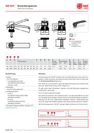
®Adjustable hand levers1.5GN 212.5Adjustabletension leversStainless SteelGN 6337.3Adjustableclamping leversSteelPage 237GN 312Safetytension leversSteelPage 246GN 6337.3Adjustableclamping leversSteelPage 238GN 312Safetytension leversSteelPage 247GN 316RatchetspannersSteelPage 239GN 125Flat adjustabletension leversSteelPage 248Page 240GN 125Flat adjustabletension leversSteelPage 243GN 99.2Adjustableclamping leversSteelPage 244GN 99.2Adjustableclamping leversSteelPage 24520Stainless Steel
®DIN 99Clamping leversSteelClamping leversTension leversGN 206Clamp nutsMalleableCast ironDIN 6306Tommy screwsSteel1.6Page 252DIN 99ClampingleversStainless SteelPage 260GN 206.1Clamp nutsMalleableCast ironPage 267GN 212Tension leversSteelPage 253DIN 6337Ball leversSteelPage 261ERFELESA-Clamping leversTechnopolymerPage 268GN 212TensionleversStainless SteelPage 254GN 99.5Clamp nutsSteelPage 262ERF.pELESA-Clamping leversTechnopolymerPage 269GN 750ControlleversSteelPage 256GN 99.6Clamp nutsStainless SteelPage 262DIN 6305Tommy nutsSteelPage 270GN 150Split hubsSintered steelPage 257GN 99.7Clamp nutswithdouble leverSteelPage 264DIN 6307Tommy nutsSteelPage 272GN 223ControlleversSteelPage 258GN 99.8Clamp nutswithdouble leverStainless SteelPage 265DIN 6304Tommy screwsSteelPage 274GN 213Turret leversSteelPage 259Stainless SteelPage 266Page 27521
®Star knobsWing screws, Wing nutsDIN 6336Star knobsCast iron,AluminiumPage 278DIN 6336Star knobsPlastic/SteelPage 279GN 6336.1GN 6336.2Star knobsPlastic/SteelVCTELESA-Star knobsTechnopolymerPage 286VCT.pELESA-Star knobs withthreaded boltTechnopolymerPage 289GN 5336Star knobsAluminiumGN 5337.3Safety-Star knobs withfemale threadedinternalpartsSteel/Stainless SteelPage 296GN 5337.3Safety-Star knobs withmale threadedinternalpartsSteel/Stainless SteelPage 296DIN 6335Star knobsCast iron,AluminiumPage 280GN 6336.1GN 6336.2Star knobsPlastic/Stainless SteelPage 290GN 5334Star knobsStainless SteelPage 298DIN 6335Star knobsPlastic/SteelPage 281GN 6336.4Star knobsPlastic/Cast ironPage 292GN 5334Star knobswiththreaded boltStainless SteelPage 299GN 6335.1GN 6335.2Star knobsPlastic/SteelPage 282GN 6336.5Star knobsTechnopolymer/Stainless SteelPage 293GN 5335Star knobsStainless SteelPage 300GN 6335.2Star knobsTechnopolymer/Stainless SteelPage 283GN 6336.3Quick releasestar knobsTechnopolymer/SteelPage 294GN 5339.5TriangularknobsStainless SteelPage 301GN 6335.4Star knobsPlastic,Cast ironPage 284Page 295Page 30222Stainless Steel
1.7GN 6335.5Star knobsTechnopolymer/Stainless SteelGN 734Wing nutsStainless SteelGN 421Knurledthumb screwsTechnopolymer/SteelPage 303GN 6335.9Star knobswithincreasedclamping forcePage 312GN 432Wing nutsStainless SteelPage 322GN 421Knurledthumb screwsTechnopolymer/Stainless SteelPage 304VB.639ELESA-Tristar knobsTechnopolymerPage 314GN 431Wing screwsStainless SteelPage 323DIN 6303Knurled nutsSteelPage 305VB.639 pELESA-Tristar knobsTechnopolymerPage 315MBTELESA-Knurled knobsTechnopolymerPage 324DIN 6303Knurled nutsStainless SteelPage 307CT.476ELESA-Wing nutsTechnopolymerPage 308CT.476 pELESA-Wing screwsTechnopolymerPage 316MBT.pELESA-Knurled knobswiththreaded boltTechnopolymerPage 319GN 420Knurled nutsTechnopolymer/SteelPage 325GN 6303.1Quick releaseknurled nutsSteelPage 326EKKELESA-KnobTechnopolymerPage 310CT.476 S-pELESA-Wing screwsTechnopolymer/Stainless SteelPage 320GN 420Knurled nutsTechnopolymer/Stainless SteelPage 82EKK.pELESA-Knurled knobScrewsTechnopolymerPage 311Stainless SteelPage 321Page 8423
®GN 676.1KnobsSteelStar knobsWing screws, Wing nutsDIN 653Flat knurledthumb screwsStainless Steel1.7Page 85GN 676.5KnobsStainless SteelPage 333DIN 467Flatknurled nutsSteelPage 85DIN 464Knurledthumb screwsSteelPage 334DIN 467Flatknurled nutsStainless SteelPage 328DIN 464Knurledthumb screwsStainless SteelPage 335Page 329DIN 466Knurled nutsSteelPage 330DIN 466Knurled nutsStainless SteelSeite 331DIN 653Flat knurledthumb screwsSteelPage 33224Stainless Steel
®Control knobsAdjustable slide units1.8GN 164Scale ringsSteelGN 727Controlknobswith adjustablespindleGN 900Adjustableslide unitsAluminiumPage 339GN 726ControlknobsAluminium,blackanodizedPage 348GN 200IndexingmechanismsSteelPage 364GN 900.1Fastening unitsAluminiumPage 340GN 726.1ControlknobsAluminium,blackanodizedPage 342GN 726.2ControlknobsAluminium,blackanodizedPage 350GN 200Indexingmechanismswithtension leversSteelPage 350GN 200IndexingmechanismsStainless SteelPage 366GN 900.2Connectingsets X-YAluminiumPage 367GN 900.3Connectingsets X-ZAluminiumPage 343GN 723.4ControlknobsAluminium,naturalcolouranodizedPage 352GN 700Adjustable knobwith steplesspositioningSteelPage 368GN 900.4Mounting platesAluminiumPage 344GN 723.3Referenceflangesfor controlknobsGN 723.4Page 354GN 215Indexing leversSteelPage 370GN 900.5Rotary platesAluminiumPage 346GN 729ControlknobsAluminium,blackanodizedPage 356GN711RulersPlastic,Stainless SteelPage 371GN 900.6RotarytablesStainless SteelPage 347Stainless SteelPage 358Page 37225
®Position indicators1.9GAELESA-PositionindicatorspendulumsystemPage 379GN 323.8Dischandwheelsfor positionindicators GAPage 380DD52RELESA-PositionindicatorsdigitalindicationPage 384BS52ELESA-Spacer platefor DD52RMD51ELESA-Hand knobfor DD51Page 388RB51RB52ELESA-Adapter bushesfor DD52Rand DD51Page 389Page 385GN 952.5Clamping platesfor DD51 andDD52RPage 386DD51ELESA-PositionindicatorsdigitalindicationPage 387BS51ELESA-Spacer platefor DD51Page 38826Stainless Steel
®GN 617IndexingplungersIndexing elementsSpring plungersGN 817IndexingplungersGN 607.1Indexingplungerswith rest positionStainless Steel2.1Page 398GN 617IndexingplungersStainless SteelPage 399GN 613Indexingplungerswithout headPage 400GN 613Indexingplungerswithout headStainless SteelPage 405GN 817IndexingplungersStainless SteelPage 405GN 717IndexingplungersPage 406GN 717IndexingplungersStainless SteelPage 409GN 607.2Indexingplungers forinstallation inthin walledequipmentPage 410GN 607.3Indexing plungerswith rest positionfor installationin thin walledequipmentPage 411GN 608IndexingplungersPage 400GN 618Indexingplungerswithout threadPage 406GN 607IndexingplungersPage 412GN 608.1Indexingplungerswith restpositionPage 401GN 617.1Indexingplungerswith restpositionPage 408GN 607IndexingplungersSteel,Stainless SteelPage 413GN 817.3IndexingplungersPage 402GN 617.1Indexingplungerswith restpositionStainless SteelPage 403Stainless SteelPage 408GN 607.1Indexingplungers withrest positionPage 409Page 414GN 822Mini indexingplungerswith/withoutrest positionPage 41627
®Indexing elementsSpring plungersGN 609Distancebushingsfor indexingplungersGN 612Cam actionindexingplungersGN 6336.7Hand knobswithindexingplungerPage 418GN 609.5Distancebushingsfor indexingplungersStainless SteelPage 418GN 417Indexingplungerswithoutrest positionPage 420GN 417Indexingplungerswithrest positionPage 421GN 412.1Mounting blocksfor indexingplungers and camaction indexingplungersZinc die castingPage 422GN 412.2Positioningbushingsfor indexingplungersSteelPage 423GN 612.1Mounting blocksfor indexingplungers andcam actionindexingplungers, SteelPage 426Page 427GN 612Cam actionindexingplungersStainless SteelPage 427GN 612.2Cam actionindexing plungerswith flangefor surfacemountingPage 428GN 612.3Cam actionindexingplungers forweldmountingPage 429GN 712Cam actionindexingplungersplunger innormalpositionprotrudedPage 430GN 712.1Cam actionindexingplungersplunger innormalpositionretractedPage 432GN 513SpringelementsPage 434Page 435GN 249Ball buttonsfor springplungersPage 436GN 250Indent blocksfor springplungersPage 437GN 614SpringplungersTechnopolymerStainless SteelPage 438GN 614.1Holder forspringplungersGN 614Page 439GN 615Springplungerswith slotPage 440GN 615Springplungerswith slotStainless SteelPage 44028Stainless Steel
2.1GN 615.3Springplungerswith hexagonsocketSteel,Stainless SteelPage 441GN 615.3Springplungerswiththread lockingSteel,Stainless SteelPage 441GN 615.2SpringplungersTechnopolymerGN 614.3Springplungersplain typeStainless SteelPage 446GN 614.2Springplungersdouble endedPage 447GN 815Springplungerswith headSteelGN 715Side thrustpinspress fitPage 452GN 714Side thrustpinswithoutthrust pinPage 453GN 713Side thrustpinsthreadedbodyPage 442GN 615.1Springplungerswith boltPage 443GN 615.1Springplungerswith boltStainless SteelPage 448GN 815Springplungerswith headStainless SteelPage 448GN 610Spring loadedshellsPage 454GN 715.2Eccentricbushesfor side thrustpinsGN 715Page 457GN 716Side thrustpinsPage 443GN 616Springplungerswith boltPage 449GN611Springplungerslong strokePage 458GN 113Balllock pinsself lockingStainless SteelPage 444GN 616Springplungerswith boltStainless SteelPage 450GN 615.7Springplungerswithlimit switchPage 462GN 113.2Balllock pinsself lockingStainless SteelPage 445Stainless SteelPage 451Page 46329
®Indexing elementsBall lock pins2.1GN 113.3Ball lockpinsself lockingStainless SteelPage 464GN 124Pins withaxiallockStainless SteelPage 465GN 114.1Pins withaxiallockPage 466GN 114.5Pins withaxiallockStainless SteelPage 466GN 114Pins withaxiallockPage 467GN 113.1Ball lockpinswith clampinglengthcompensationPage 468GN 111Ball chainsPage 46930Stainless Steel
®Screws, NutsWashers2.2GN 913.3Grub screwswith brass orplastic padGN 709.3Clamping padswith heightadjustmentGN 346Ball jointthrust padsPage 472GN 913.5Grub screwswith brass orplastic padStainless SteelPage 480GN 709.1Clamping padswithmale threadPage 489GN 347Hexagon nutswith ballsocketPage 473GN 913.2Grub screwswith hardenednosePage 482GN 709.2Clamping padswithfemale threadPage 490GN 806Protective capsPage 474GN 605Ball pointscrewsPage 483DIN 6332Grub screwswiththrust pointPage 491GN 251Setting boltsPage 476GN 605Ball pointscrewsStainless SteelPage 484DIN 6311Thrust padsPage 492GN 251.2Setting boltswith limitswitchPage 477GN 606Ball pointscrewsPage 486GN 6311.1Thrust padsSteel/TechnopolymerPage 493GN 551.1Grub screwsthreaded rodsPage 478GN 606Ball pointscrewsStainless SteelPage 487GN 638Ball jointedlevelling feetSteel,Stainless SteelPage 494GN 252Blanking plugsPage 479Stainless SteelPage 488Page 49531
®Screws, NutsWashersDIN 444Swing boltsPage 496DIN 444Swing boltsStainless SteelDIN 6379Studsfor T-NutsPage 504DIN 787T-Slot boltsGN 506.1T-Nutsfor linkingaluminiumextrusionsSteel,Stainless SteelPage 511DIN 6330Hexagon nutswith sphericalseatingPage 496GN 1524Swing boltswith fullythreaded boltPage 497GN 444.2Swing nutsPage 505GN 508.2T-Nutsslip proofPage 506GN 508.1RhombusT-NutsPage 512DIN 6330Hexagonnutswith sphericalseatingStainless SteelPage 512DIN 6331Collar nutsPage 498GN 732Cylinder headshoulder boltsPage 507GN 505T-Nutsfor aluminiumextrusionsPage 513GN 350LevellingsetsSteel,Stainless SteelPage 500DIN 508T-NutsPage 508GN 507T-Nutsfor linkingaluminiumextrusionsPage 514GN 350.1LevellingsetsSteel,Stainless SteelPage 502DIN 508T-NutsStainless SteelPage 509GN 506T-Nutsfor linkingaluminiumextrusionsPage 516GN 350.2LevellingsetsSteel,Stainless SteelPage 503Page 510Page 51732Stainless Steel
2.2GN 350.3SphericallevellingwashersSteel,Stainless SteelPage 518DIN 6319SphericalwashersGN 184CountersunkwashersPage 527GN 184.5CountersunkwashersStainless SteelGN 705Set collarsStainless SteelPage 532GN 706Semi-splitset collarsPage 520DIN 6319SphericalwashersStainless SteelPage 527GN 185BezeldiscsStainless SteelPage 534GN 706Semi-splitset collarsStainless SteelPage 521GN 6339Heavy dutywashersPage 528GN 338Discswith cover capPage 534GN 707Splitset collarsPage 522GN 187Serratedlocking platesPage 529GN 183C-WashersPage 535GN 707Splitset collarsStainless SteelPage 524GN 187.1Guide potsPage 530DIN 6371CaptiveC-WashersPage 535DIN 6340WashersPage 526GN 187.2Thrust springsPage 531GN 705Set collarsPage 536DIN 1804SlottedlocknutsPage 526Stainless SteelPage 532Page 53733
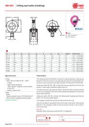
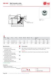
®DIN 580Liftingeye boltsmaleScrews, NutsWashersGN 509.3SpringringsStainless Steel2.2Page 538DIN 580Liftingeye boltsmaleStainless SteelPage 545DIN 6885KeysSteelPage 538DIN 582Liftingeye boltsfemalePage 546DIN 6885KeysStainless SteelPage 539DIN 582Liftingeye boltsfemaleStainless SteelPage 547GN 230ShallowT-NutsPage 539GN 581Liftingeye bolts(rotating)Page 548GN 770Guide bushesPage 540GN 509Balltransfer unitsSteel,Stainless SteelPage 550GN 771Guide pinsPage 542GN 509.1Balltransfer unitsSteel,Stainless SteelPage 551Page 54434Stainless Steel
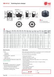
®Clamping boltsEccentrical cams2.3GN 927Clamping leverswitheccentricalcamGN 918.7ClampingboltsStainless SteelGN 928Shaftclampingunits'trueround'Page 554GN 919Hubs witheccentricalcamPage 561GN 917Double camleversPage 570Page 556GN 918EccentricalcamsPage 562GN 917.1Double camleversStainless SteelPage 558GN 918.5EccentricalcamsStainless SteelPage 562GN 921WedgeclampsPage 558GN 918.1ClampingboltsPage 564GN 921.1Locking platfor GN 921Page 560GN 918.6ClampingboltsStainless SteelPage 564GN 920WedgeclampsPage 560GN 918.2ClampingboltsPage 566GN411Centring boreclampsPage 561Page 568Stainless Steel35
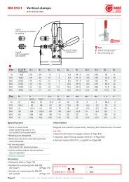
®Toggle clampsPower clamps, Hook clampsGN 810VerticalclampsGN 910.3Knee levermodulesfor weldingGN 812VerticalclampsPage 576GN 810VerticalclampsStainless SteelPage 590GN 910.5Handleaccessories forKnee levermodulesPage 594GN 820HorizontalclampsPage 578GN 810.1VerticalclampsPage 580GN 810.1VerticalclampsStainless SteelPage 582GN 910Verticalclampsheavy duty typeªLonglifeºPage 591GN 910.6Lever armHandleaccessories forKnee levermodulesPage 591GN 910.7Clamping armelongationaccessories forKnee levermodulesPage 591GN 910.8Bushingaccessories forKnee levermodulesPage 596GN 820HorizontalclampsStainless SteelPage 598GN 820.1HorizontalclampsPage 600GN 820.1HorizontalclampsStainless SteelPage 584GN 910.1Verticalclampsheavy duty typeªLonglifeºPage 591GN 910.9Base plateaccessories forKnee levermodulesPage 602GN 840PlungerclampsPage 586GN 910.2Knee levermodulesto screw-onPage 591GN 813VerticalclampsPage 604GN 844PlungerclampsPage 588Page 592Page 60636Stainless Steel
2.4GN 841Plunger clampsGN 851.1Latch clampsGN 860PneumaticallyoperatedclampsPage 608GN 842Plunger clampsPage 622GN 851.1LatchclampsStainless SteelPage 632GN 861PneumaticallyoperatedclampsPage 610GN 843.1Plunger clampsPage 624GN 851.2Latch clampsPage 634GN 862PneumaticallyoperatedclampsPage 612GN 843.1PlungerclampsStainless SteelPage 626GN 852Latch clampsheavy duty typewith fixing holesSteelPage 636GN 863PneumaticallyoperatedclampsPage 614GN 850Hook clampsPage 628GN 852Latch clampsheavy duty typefor weldingSteelPage 638GN 890PneumaticallyoperatedclampsPage 616GN 851Latch clampsPage 618GN 851LatchclampsStainless SteelPage 620Stainless SteelPage 628GN 852Latchclampsheavy duty typewith fixing holesStainless SteelPage 630GN 852Latchclampsheavy duty typefor weldingStainless SteelPage 630Page 640GN 807ClampingboltsSteel,Stainless SteelPage 642GN 708ClampingboltsSteel,Stainless SteelPage 64337
®Toggle clampsPower clamps, Hook clampsGN 802Clamping boltsSteelGN 867Holders forclamping boltsGN 871Levelling shimsPage 644GN 903ClampingboltsSteel,Stainless SteelPage 656GN 867.1Static holdersPage 663GN 873Collar clampsPage 645GN 804Clamping boltsSteelPage 657GN 868Holders forclamping jawsPage 664GN 870Guide bushesPage 646GN 896.1GN 896.2GN 896.3Proximityswitcheswith mountingbracketPage 647GN 864Power clampsPage 658GN 868.1Holders forclamping jawsPage 659GN 869.1Static holdersPage 666GN 893.1GN 893.2GN 893.3Proximityswitcheswith holderPage 667GN 821HookclampsSteel,Stainless SteelPage 650GN 865Power clampsPage 660GN 869.2Holders forclamping jawsPage 668GN 831HookclampsSteel,Stainless SteelPage 652GN 866Power clampsPage 661GN 872Clamping jawsblankPage 670GN 831.1HookclampsSteel,Stainless SteelPage 654Page 662Page 67238Stainless Steel
2.4GN 832HookclampsSteel,Stainless SteelPage 673GN 832.1HookclampsSteel,Stainless SteelPage 674GN 832.2HookclampsSteel,Stainless SteelPage 676GN 832.3HookclampsSteel,Stainless SteelPage 677GN 832.4HookclampsSteel,Stainless SteelPage 678GN 833HookclampsSteel,Stainless SteelPage 679Stainless Steel39
®Levelling feetDoor locks, HingesGN 343.1Levelling feetSteelGN 343.8LevellingfeetTechnopolymer/Stainless SteelGN 340Levelling feetSteelPage 682GN 343.2Levelling feetSteelPage 687GN 342.1Levelling feetvibrationabsorbingPage 698GN 340.5LevellingfeetStainless SteelPage 682GN 343.3Levelling feetTechnopolymer/SteelPage 688GN 342.2Levelling feetvibrationabsorbingPage 698GN 341LevellingfeetStainless SteelPage 685GN 343.4Levelling feetTechnopolymer/SteelPage 685GN 343.5LevellingfeetStainless SteelPage 688GN 344.1ELESA-Levelling feetTechnopolymer/SteelPage 690GN 344.6ELESA-Levelling feetTechnopolymer/Stainless SteelPage 699GN 341.1Levellingfeetfor use inhygieneenvironmentStainless SteelPage 700GN 440Levelling feetSteelPage 686GN 343.6LevellingfeetStainless SteelPage 692GN 345.1ELESA-Levelling feetTechnopolymer/SteelPage 702GN 440.5LevellingfeetStainless SteelPage 686GN 343.7LevellingfeetTechnopolymer/Stainless SteelPage 694GN 345.6ELESA-Levelling feetTechnopolymer/Stainless SteelPage 702GN 339Levelling feetSteelPage 687Page 696Page 70440Stainless Steel
2.5GN 349Threadedmounting platesforlevelling feetSteelPage 705GN 348.1Insert bushesfor profiledsquare tubesTechnopolymerGN 115Locksnot lockablePage 716GN 115LockslockableGN 237Hinges for screwmountingAluminiumPage 727GN 237Hingesfor screwmountingStainless SteelPage 706GN 992Threadedtube insertsfor tubingsGN 990AluminiumPage 708GN 218Cam latchesPage 718GN 115.1Mini-LocksPage 720GN 115Door locksStainless SteelPage 727CFMELESA-HingesTechnopolymerPage 728GN 238Hinges for screwmounting,adjustablePage 709GN 117Door locksPage 722GN 123Sheet metalpunchesfor mountingof locksPage 730GN 127Hinges for screwmounting,adjustablePage 710GN 119Door locksPage 723GN 161HingesZinc die castingPage 732GN 129Hinges for screwmountingPage 712GN 116Door locksPage 724GN 237Hinges for screwmountingZinc die castingPage 734GN 128Hinges for weldmountingPage 714Stainless SteelPage 727Page 73541
®GN 743GN 743.1Oillevelsight glassesAluminium/naturalglassPage 738GN 744Prismaticoillevelsight glassesAluminium/TechnopolymerPage 739GN 743.2GN 743.3Oillevelsight glassesBrass/naturalglassPage 740GN 743.5Oillevelsight glassesStainless Steel/naturalglassOil level sight glassesPlugsGN 541.1ELESA-Oillevelsight glassesTechnopolymerPage 746HCZELESA-OillevelindicatorsTechnopolymerPage 748GN 749Threaded plugsSteelPage 750GN 741GN 742Threaded plugsAluminiumSFPELESA-Breather capsTechnopolymerPage 7582.6Page 742GN 743.6ATEX-Levelsight glassesAluminium/naturalglassPage 752GN 738GN 738.1Magnetic plugsAluminiumPage 743GN 743.7GN 743.8Oillevelsight glasseswith conicalthreadBrassPage 744GN 537Oillevelsight glassesAluminium/PerspexPage 753TNELESA-Threaded plugsTechnopolymerPage 754GN 543.1Fixing nutsfor oillevelsight glassesPage 745Page 75642Stainless Steel
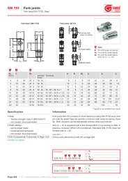
®Universal joints, Fork joints2.7DIN 808Universaljointswithfriction bearingGN 648.1Ball jointswithfemale threadGN 782Ball jointsPage 766GN 808.2Universaljointshafts withfriction bearingPage 776GN 648.2Ball jointswiththreaded boltPage 784DIN 71802Angledball jointsPage 767DIN 808Universaljoints withfriction bearingStainless SteelPage 777GN 648.5Ball jointswithfemale threadStainless SteelPage 786DIN 71802Angledball jointsStainless SteelPage 768DIN 808Universaljointswithneedle bearingPage 778GN 648.6Ball jointswiththreaded boltStainless SteelPage 787GN 710Dust capsfor angledball jointsDIN 71802Page 770GN 808.3Universaljointshafts withneedle bearingPage 779GN 751Fork jointsFork headsDIN 71752Page 789GN 240Quick-fitcouplingsPage 771GN 908Universaljointsfor ordinaryapplicationsPage 780GN 751Fork jointsFork headsDIN 71752Stainless SteelPage 790GN 240.1Quick-fitcouplingsPage 772GN 808.1Gaiters foruniversaljointsPage 781GN 752Joint piecesSteel,Stainless SteelPage 792GN 240.2Quick-fitcouplingsPage 773Stainless SteelPage 783Page 79343
®Tube clamp connectorsLinear actuatorsGN 131Two-wayconnectorclampsAluminium,Stainless SteelPage 798GN 132Two-wayconnectorclampsAluminiumPage 800GN 133Two-wayconnectorclampsAluminiumGN 147FlangedconnectorclampsAluminiumPage 810GN 162Base plateconnectorclampsAluminium,Stainless SteelPage 811GN 163Base plateconnectorclampsAluminiumGN 191T-AngleconnectorclampsAluminium,Stainless SteelPage 819GN 192T-AngleconnectorclampsAluminiumPage 820GN 193T-AngleconnectorclampsAluminiumPage 801GN 134Two-wayconnectorclampsAluminiumPage 812GN 165Base plateconnectorclampsAluminiumPage 822GN 194T-AngleconnectorclampsAluminiumPage 802GN 141Flangedtwo-wayconnectorclampsAluminiumPage 804GN 145FlangedconnectorclampsAluminium,Stainless SteelPage 806GN 146FlangedconnectorclampsAluminiumPage 807Page 814GN 166Off-setbase plateconnectorclampsAluminiumPage 816GN 167Wide base plateconnectorclampsAluminiumPage 817GN 171Flangedbase plateconnectorclampsAluminiumPage 818Page 824GN 195T-AngleconnectorclampsAluminiumPage 826GN 231TubesupportsAluminiumPage 828GN 241TubeconnectorsAluminiumPage 82944Stainless Steel
2.8GN 271SwivelclampconnectorbasesAluminiumGN 278SwivelclampconnectorsAluminiumGN 287SwivelclampconnectorjointsAluminiumPage 832GN 272SwivelclampconnectorbasesAluminiumPage 839GN 281SwivelclampconnectorjointsAluminiumPage 848GN 288SwivelclampconnectorjointsAluminiumPage 833GN 273SwivelclampconnectorsAluminiumPage 834GN 274SwivelclampconnectorsAluminiumPage 842GN 282SwivelclampconnectorjointsAluminiumPage 843GN 283SwivelclampconnectorjointsAluminiumPage 849GN 990ConstructiontubingsSteel,Aluminium,Stainless SteelPage 850GN 991Tube end plugsPage 835GN 275SwivelclampconnectorsAluminiumPage 844GN 284SwivelclampconnectorjointsAluminiumPage 852GN 911.3Adjustablehandle setsSteelPage 836GN 276SwivelclampconnectorsAluminiumPage 845GN 285SwivelclampconnectorjointsAluminiumPage 853GN 911.4Adjustablehandle setsStainless SteelPage 837GN 277SwivelclampconnectorsAluminiumPage 846GN 286SwivelclampconnectorjointsAluminiumPage 853GN 911.1Cap headscrew setsSteelPage 838Stainless SteelPage 847Page 85445
®GN 911.2Cap headscrew setsStainless SteelTube clamp connectorsLinear actuatorsGN 132.1GN 132.2Linear actuatorconnectorsAluminiumGN 273.1Swivelclamplinear actuatorconnectorsAluminium2.8Page 854GN 911.5Hexagon headscrew setsSteelPage 855GN 911.6Hexagonheadscrew setsStainless SteelPage 865GN 145.1Flangedlinear actuatorconnectorsAluminium,Stainless SteelPage 866GN 146.1Flangedlinear actuatorconnectorsAluminiumPage 872GN 274.1Swivelclamplinear actuatorconnectorsAluminiumPage 873GN 736.18Handwheelforlinear actuatorÆ 18Page 855GN 291LinearactuatorsSteel,Stainless SteelPage 860GN 292LinearactuatorsSteel,Stainless SteelPage 867GN 162.1Base platelinear actuatorconnectorsAluminium,Stainless SteelPage 868GN 163.1Base platelinear actuatorconnectorsAluminiumPage 874GN 323.30GN 323.40Handwheelforlinear actuatorÆ 30 and Æ 40Page 874GN 324.40GN 324.50Handwheelforlinear actuatorÆ 40 and Æ 50Page 862GN 293LinearactuatorsSteel,Stainless SteelPage 863GN 131.1GN 131.2Linear actuatorconnectorsAluminium,Stainless SteelPage 864Page 869GN 191.1T-Anglelinear actuatorconnectorsAluminium,Stainless SteelPage 870GN 192.1T-Anglelinear actuatorconnectorsAluminiumPage 871Page 874/875GN 295Installation kitsfor positionindicators usedon linearactuatorsPage 877GN 299Longitudinalscales forlinear actuatorsPage 87846Stainless Steel
®Stainless Steel47
HandlesKnobs1.1
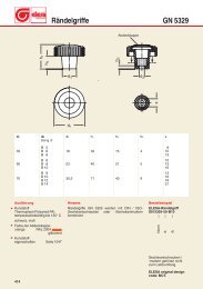
®Revolving handles GN 798d1 d2 d3 d4 l1 l2 l3 l416 M 6 ± 10 13 41,5 12 2,5 1518 M 6 M 8 10 14,5 56 13 2,5 1922 M 8 M 10 14 18,5 59 14 2,5 2124 M 8 M 10 14 18,5 74 16 2,5 2725 M 10 ± 16 20 84 16 2,5 30SpecificationPlastic KTTechnopolymer (Polyamide PA)temperature resistantup to 90° Cblack, matt finishAluminium ALturned and polishedSpindle steelzinc plated,blue passivatedPlasticcharacteristics Page 897InformationTypicalin design are our revolving handles GN 798(photo page 54) with their stepped shape consistingof two cylinders giving the operator a bettergrip.Handwheels GN 321 Page 164GN 322 Page 168GN 323 Page 166GN 324 Page 170How to orderRevolving handleGN 798-KT-24-M10Code No. ÐMaterialÐd1 Ðd2 Ð50
®Stainless Steel-spindleRevolving handles GN 798.11.1d1 d2 d3 d4 l1 l2 l3 l416 M 6 ± 10 13 41,5 12 2,5 1518 M 6 M 8 10 14,5 56 13 2,5 1922 M 8 M 10 14 18,5 59 14 2,5 2124 M 8 M 10 14 18,5 74 16 2,5 2725 M 10 ± 16 20 84 16 2,5 30SpecificationPlastic KTTechnopolymer (Polyamide PA)temperature resistantup to 90° Cblack, matt finishSpindleStainless SteelGerman MaterialNo. 1.4305Stainless Steelcharacteristics Page 894Plasticcharacteristics Page 897InformationTypicalin design are our revolving handlesGN 798.1 (photo page 54) with their steppedshape consisting of two cylinders giving the operatora better grip.How to orderRevolving handleGN 798.1-KT-16-M6Code No. ÐMaterialÐd1 Ðd2 Ð51
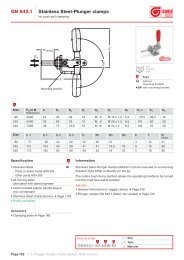
®with hold in both positionsRetractable handles GN 798.3d1 d2 d3 l1 » l2 l3 l4 » l516 M 5 16 58 15 5 52,5 9,518 M 5 16 72,5 15 5 67 9,522 M 6 20 80,5 19,5 6 74 10,524 M 6 20 95,5 19,5 6 89 10,525 M 6 20 105,5 19,5 6 98,5 10,5SpecificationHandlePlastic KTTechnopolymer (Polyamide PA)temperature resistantup to 90° Cblack, matt finishrevolvingRetractable mechanismSteelblackenedPlasticcharacteristics Page 897InformationTypical in design are our retractable handlesGN 798.3 (photo page 54) with their steppedshape consisting of two cylinders giving the operatora better grip, especially when pulling the handleout from its locked position before it can be foldedback into the rest position.Retractable handles GN 798.3 are suitable whenthe handle must be withdrawn during automaticoperations. The handle is pulled out of its taperseating in the direction of the arrow and then tilted.A compression spring locks the handle in both endpositions.A positive lock is achieved in the operating positionby way of a taper seating.Handwheels GN 322.3(with retractable handle GN 598.3) Page 188How to orderRetractable handleGN 798.3-KT-22Code No. ÐMaterialÐd1 Ð52
®with hold in both positionsSt. Steel-Retractable handles GN 798.51.1d1 d2 d3 l1 » l2 l3 l4 » l516 M 5 16 58 15 5 52,5 9,518 M 5 16 72,5 15 5 67 9,522 M 6 20 80,5 19,5 6 74 10,524 M 6 20 95,5 19,5 6 89 10,525 M 6 20 105,5 19,5 6 98,5 10,5SpecificationHandlePlastic KTTechnopolymer (Polyamide PA)temperature resistantup to 90° Cblack, matt finishrevolvingRetractable mechanismStainless SteelGerman MaterialNo. 1.4305Stainless Steelcharacteristics Page 894Plasticcharacteristics Page 897InformationTypical in design are our retractable handlesGN 798.5 (photo page 54) with their steppedshape consisting of two cylinders giving the operatora better grip, especially when pulling the handleout from its locked position before it can be foldedback into the rest position.Retractable handles GN 798.5 are suitable whenthe handle must be withdrawn during automaticoperations. The handle is pulled out of its taperseating in the direction of the arrow and then tilted.A compression spring locks the handle in both endpositions.A positive lock is achieved in the operating positionby way of a taper seating.How to orderStainless Steel-Retractable handleGN 798.5-KT-25Code No. ÐMaterialÐd1 Ð53
®Revolving handles GN 798 P. 50Revolving handles with Stainless Steel-spindle GN 798.1 P. 51Retractable handles GN 798.3 P. 52Stainless Steel-Retractable handles GN 798.5 P. 5354
®1.1Revolving handles GN 598 P. 56Revolving handles with Stainless Steel-spindle GN 598.1 P. 57Retractable handles GN 598.3 P. 58Stainless Steel-Retractable handles GN 598.5 P. 59Retractable safety handles GN 598.7 P. 6055
®Revolving handles GN 598d1 d2 d3 d4 l1 l2 l3metricUNC14 M 6 ± ± 8 11 28 10 0,518 M 6 ±1 / 4 ´ 20 10 15 40 12 2,521 M 6 M 81 / 4 ´ 20 10 17 50 13 2,522 M 6 M 8 ± 10 18 56 13 2,523 M 8 M 105 / 16 ´ 18 13 19 65 14 2,526 M 8 M 103 / 8 ´ 16 13 21 80 16 2,528 M 10 ± ± 13 22 90 16 2,531 M 12 ±1 / 2 ´ 13 14 25 102 20 2,5SpecificationPlastic KUDuroplast (Phenolic PF)only sizes 18 ¸ 31temperature resistantup to 110° Cblack, shiny finishPlastic KTTechnopolymer (Polyamide PA)only sizes 14 ¸ 28temperature resistantup to 80° Cblack, matt finishSteel STonly sizes 18 ¸ 31Plastic coatedmatt black, textured finishSpindle steelzinc plated, blue passivatedPlasticcharacteristics Page 897InformationRevolving handles GN 598 (photo page 55) arenoted for their modern design and they blend inwell with the rectangular shaped rim handwheels.Steelhandles are mainly used on safetyhandwheels to increase imbalance and thus avoidfree wheeling.Cylindrical knobs GN 519(with internal thread) Page 72How to orderRevolving handleGN 598-KU-21-M8Code No. ÐMaterialÐd1 Ðd2 Ð56
®Stainless Steel-spindleRevolving handles GN 598.11.1d1 d2 d3 d4 l1 l2 l318 M 6 10 15 40 12 2,521 M 6 10 17 50 13 2,523 M 8 13 19 65 14 2,526 M 10 13 21 80 16 2,528 M 10 13 22 90 16 2,531 M 12 14 25 102 20 2,5SpecificationPlastic KUDuroplast (Phenolic PF)all sizestemperature resistantup to 110° Cblack, shiny finishPlastic KTTechnopolymer (Polyamide PA)only sizes 18 ¸ 28temperature resistantup to 80° Cblack, matt finishSpindleStainless SteelGerman MaterialNo. 1.4305Stainless Steelcharacteristics Page 894Plasticcharacteristics Page 897InformationRevolving handles GN 598.1 (photo page 55) arenoted for their modern design and they blend inwell with the rectangular shaped rim handwheels.How to orderRevolving handleGN 598.1-KU-21-M6Code No. ÐMaterialÐd1 Ðd2 Ð57
®with hold in both positionsRetractable handles GN 598.3d1 d2 d3 l1 » l2 l3 l4 » l518 M 5 16 57 15 5 52 9,521 M 5 16 67 15 5 62 9,522 M 5 16 73 15 5 68 9,523 M 6 20 87 19,5 6 80 10,526 M 6 20 102 19,5 6 95 10,528 M 8 26 118 26 10 106 16SpecificationHandlePlastic KUDuroplast (Phenolic PF)temperature resistantup to 110° Cblack, shiny finishrevolvingRetractable mechanismSteelblackenedPlasticcharacteristics Page 897InformationRetractable handles GN 598.3 (photo page 55)are suitable when the handle must be withdrawnduring automatic operations. The handle is pulledout of its taper seating in the direction of the arrowand then tilted. A compression spring locks thehandle in both end positions.A positive lock is achieved in the operating positionby way of a taper seating.Handwheels withSafety handle VDS+IR Page 186VRTP+IR Page 187Cranked handles GN 471.3 Page 150Cranked handles GN 472.3 Page 151Retractablesafety handles GN 598.7 Page 60How to orderRetractable handleGN 598.3-KU-26Code No. ÐMaterialÐd1 Ð58
®with hold in both positionsSt. Steel-Retractable handles GN 598.51.1d1 d2 d3 l1 » l2 l3 l4 » l523 M 6 20 87 19,5 6 80 10,526 M 6 20 102 19,5 6 95 10,528 M 8 26 118 26 10,5 106 16SpecificationHandlePlastic KUDuroplast (Phenolic PF)temperature resistantup to 110° Cblack, shiny finishrevolvingRetractable mechanismStainless SteelGerman MaterialNo. 1.4305Stainless Steelcharacteristics Page 894Plasticcharacteristics Page 897InformationRetractable handles GN 598.5 (photo page 55)are suitable when the handle must be withdrawnduring automatic operations. The handle is pulledout of its taper seating in the direction of the arrowand then tilted. A compression spring locks thehandle in both end positions.A positive lock is achieved in the operating positionby way of a taper seating.How to orderStainless Steel-Retractable handleGN 598.5-KU-26Code No. ÐMaterialÐd1 Ð59
®Retractable safety handles GN 598.7d1 d2 d3 l1 l2 » l3 l4 l5(arrested)23 M 6 20 79 88 22 13 5,526 M 6 20 93 102 22 13 5,5SpecificationHandlePlastic KUDuroplast (Phenolic PF)temperature resistantup to 110° Cblack, shiny finishrevolvingRetractable mechanismSteelblackenedPlasticcharacteristics Page 897InformationRetractable handles GN 598.7 (photo page 55)are suitable for applications where the handle mustnot remain in the operating position.In order to bring the handle into the operating positionit has to be turned first through 90° to a stopagainst a torsion spring and then it is pushedagainst spring pressure into its hold position. Bymaintaining the forward thrust on the handle, thehandwheelcan easily be rotated.When releasing the handle, the springs return itback to the retracted position.Hanwheels withsafety handle GN 322.7 Page 189How to orderRetractable safety handleGN 598.7-KU-23Code No. ÐMaterialÐd1 Ð60
®Revolving cylindrical handles GN 599.51.1d1 d2 l1 d3 l213 1814 M6 9 8 2016 23SpecificationPlasticTechnopolymer (Polyamide PA)temperature resistantup to 80° Cblack, matt finishSpindleStainless SteelStainless Steelcharacteristics Page 894Plasticcharacteristics Page 897InformationCylindrical handles GN 599.5 are mainly used onsmall handwheels (GN 736, GN 736.1) which areinstalled for control purposes where low torque isrequired (fingertip grip).How to orderRevolving cylindricalhandleGN 599.5-14-M6-9Code No. Ðd 1 Ðd 2 Ðl 1 Ð61
®Extract fromRevolving handles DIN 98Type D with plain shaftType E with threaded shaftd1 d2 h8 d3 d4 h13 l1 » l2 l3 InternalType D Type E hexagon16 7 M 6 10 49 11 5,5 320 8 M 8 13 61 13 6 425 10 M 10 16 75 14 8 532 13 M 12 20 95 21 10,5 636 16 M 16 22 106 26 11 8SpecificationSteel STall sizeszinc plated, blue passivatedAluminium ALall sizesfine turned, polishedPlastic KTTechnopolymer (Polyamide PA)only sizes 16 ¸ 32temperature resistantup to 110° Cblack, matt finishSpindle steelzinc plated, blue passivatedISO-FundamentalTolerances Page 888Plasticcharacteristics Page 89762InformationThis handle is supplied unassembled so that theshaft can be press fitted or screwed into a tappedblind bore prior to assembly.How to orderRevolving handleDIN 98-KT-32-DCode No. ÐMaterialÐd1 ÐType Ð
®Extract fromFixed handles DIN 391.1Type D with plain shaftType E with threaded shaftd1 d2 h8 d3 d4 h13 l1 » l2 l3 InternalType D Type E hexagon16 7 M 6 10 50 11 7 320 8 M 8 13 64 13 8 425 10 M 10 16 80 14 10 532 13 M 12 20 100 21 13 636 16 M 16 22 112 26 14 8SpecificationSteel STall sizesturned and polishedPlastic KTTechnopolymer (Polyamide PA)only sizes 20, 25, 32, Type Etemperature resistantup to 100° Cblack, matt finishshaft steel, blackenedISO-FundamentalTolerances Page 888Plasticcharacteristics Page 897How to orderFixed handleDIN 39-ST-25-ECode No. ÐMaterialÐd1 ÐType Ð63
®Revolving ball knobs GN 319.2d1 d2 d3 l1 l2 l325 M 6 10 11 37,5 1532 M 8 13 13 48 1940 M10 16 14 61 2450 M12 20 21 78 31SpecificationPlasticDuroplast (Phenolic PF)temperature resistantup to 110° Cblack, shiny finishShaft steelzinc plated, blue passivatedPlasticcharacteristics Page 897InformationRevolving ball knobs GN 319.2 can be utilizedinstead of revolving handles i. e. with handwheels.Revolving ball knobs have the same assemblydimensions as the handles DIN 39, DIN 98 andGN 598.How to orderRevolving ball knobGN 319.2-32-M8Code No. Ðd1 Ðd2 Ð64
®1.1Ball knobs DIN 319 and alternativesBall knobs (Duraplast, Technopolymer) DIN 319 P. 66Ball knobs (Steel, Aluminium, Stainless Steel) DIN 319 P. 67Ball knobs (Duroplast, Technopolymer, Press on type) DIN 319 P. 6865
®PlasticExtract fromBall knobs DIN 319Type C with tapped hole (no bush)Type E with tapped bushd1 d2 d3 d4 » h t1 t2Plastic Plastic min. min.KU KT KU KTType C Type C Type E Type EThread Thread Thread Thread12 M 4 ± ± ± ± ± ± 6 11,2 6,5 ±16 M 4 M 5 ± M 4 M 5 M 4 ± 8 15 7 620 M 5 M 6 ± M 5 M 6 M 5 M 5 12 18 9 7,525 M 5 M 6 M 8 M 6 M 8 M 6 M 6 15 22,5 11 930 M 8 ± ± ± ± ± ± 15 28 14,5 ±32 M 6 M 8 M 10 M 8 M 10 M 8 M 8 18 29 14,5 1235 M10 ± ± ± ± ± ± 18 32,5 18 ±40 M 8 M 10 M 12 M 10 M 12 M 10 ± 22 37 18 1550 M12 ± ± ± ± M12 ± 27 46 21 18SpecificationPlastic KUDuroplast (Phenolic PF)black (red optional,specify 'red' on order;not for all types)Flash removed and polishedBush (Type E)steel, zinc plated or brass (MS)(if ªbrassº is desired ad ªMSº onorder code)Plastic KTTechnopolymer (Polyamide PA)shock resistantblack, matt finishInsert (Type E)steel, zinc platedInformationPhoto page 65Ball knobs (Press on type)DIN 319 Type L and M Page 68Gear lever handles GN 310 Page 76How to orderBall knobDIN 319-KT-25-M6-ECode No. ÐMaterialÐd1 Ðd2 (d3) ÐType Ð66
®Steel/ Aluminium / Stainless SteelExtract fromBall knobs DIN 3191.1Type C with tapped holeType K with plain hole H7d1 d2 d3 H7 d4 h t1 t2Type C Type K min. min.16 M 4 B 6 8 15 7 920 M 5 B 8 12 18 9 1125 M 6 B 10 15 22,5 11 1432 M 8 B 12 18 29 14,5 1740 M 10 B 16 22 37 18 2250 M 12 B 20 27 46 21 28SpecificationSteel STpolishedAluminium ALpolishedStainless Steel NIGerman MaterialNo. 1.4305only Type Conly sizes 16, 20, 25, 32, 40matt shot-blastedISO-FundamentalTolerances Page 888Stainless Steelcharacteristics Page 894InformationPhoto page 65How to orderBall knobDIN 319-NI-25-M6-CCode No. ÐMaterialÐd1 Ðd2 (d3) ÐType Ð67
®Press on typeExtract fromBall knobs DIN 319Type L with tolerance ringType M with tapered bored1 d2 (Bore B) ± t1 d4 (Bore B) ± t2 d3 » hType L Type L Type L Type M Type M16 B 4 - 11 ± ± B 4 - 9 ± 8 1520 B 5 - 13 ± ± B 5 - 12 B 6 - 12 12 1825 B 6 - 16 B 8 - 15 B 10 - 15 B 6 - 16 B 8 - 16 15 22,532 B 8 - 15 B 10 - 20 B 12 - 20 B 8 - 17 B 10 - 17 18 2940 B 10 - 25 B 12 - 23 ± B 10 - 22 B 12 - 22 22 3750 B 12 - 20 B 16 - 23 ± ± ± 28 46SpecificationType LPlastic KUDuroplast (Phenolic PF)black, shiny finishTolerance ringspring steelType MPlastic KTTechnopolymer (Polyamide PA)shock resistantblack, matt finishISO-FundamentalTolerances Page 888Plasticcharacteristics Page 897InformationWhen ball knobs DIN 319 (photo page 65) type Land M are used the shaft does not require athread.The ball knobs are driven on to the shaft with lightmallet blows to the ball knobs. The shaft endshould have a radius or chamfered (30° C).Before the assembly of the knobs, type L the tollerancering is to be inserted into the drilling. Furtherit is to be noted that the button is put on perpendicularand / or axially parallel. Otherwise the knobmay break.Type M ball knobs are a cheaper solution, however,the pulling off force is less predictable.How to orderBall knobDIN 319-KU-40-B10-LCode No. ÐMaterialÐd1 Ðd2 ÐType ÐBall KnobDIN 319-KT-32-B10-MCode No. ÐMaterialÐd1 Ðd4 ÐType Ð68
®1.1Alternatives to ball knobsWaist shaped knobs GN 75 P. 86Mushroom type knobs GN 76 P. 87Elliptical shaped knobs GN 201 P. 74Taper knobs GN 419 P. 75Cylindrical knobs GN 519 P. 72Cylindrical knobs GN 519.1 P. 7369
®Domed gear knobs I.622d1 d2 d3 d4 h t1 t2 ± 0,5 t316 M 6 ± B 6 ± 12 25 16 3,5 1720 M 8 ± B 8 ± 14 32 20 3,5 2126 M 8 M 10 B 8 B 10 17 42 30 5 25 / 3034 M 10 M 12 B 10 B 12 21 55 35 8 40SpecificationPlastic Technopolymer(Polyamide PA)temperature resistant up to 80° Cblack SW RAL 9005shiny finishred RT RAL 3000shiny finishtypewith bore B onlywhite CL RAL 9002Cleanline shiny finish(not size 26-B 8)temperature resistant up to 50° CISO-FundamentalTolerances Page 888Plasticcharacteristics Page 897InformationDomed gear knobs I.622 are very often used in placeof ball knobs DIN 319 for use on gear leversand shafts.Operating knobs are very often chosen for ergonomicalreasons.Domed gear knobs I.622 with bore (B) are mountedby driving them over the shaft with a plastic hammer.A threaded shaft is not required. The shaftend should preferably be slightly rounded or chamfered(30°).How to orderELESA-Domedgear knobI.622-20-M8-SWCode No. Ðd1 Ðd2 (d3) ÐColour Ð70ELESA original design
®1.171
®Cylindrical knobs GN 519d1 d2 d3 l1 l2 l3 ± 0,5min.14 M 5 ± 11 28 12 1,518 M 6 M 8 15 40 25 3,521 M 6 M 8 17 50 26 / 35 3,5 / 7,523 M 8 M 10 19 65 30 / 40 7,526 M 10 M 12 21 80 55 7 / 1028 M 10 M 12 22 90 55 / 58 7 / 829 M 12 ± 23 116 58 831 M 12 ± 25 102 58 8SpecificationPlasticDuroplast (Phenolic PF)temperature resistantup to 110° Cblack, shiny finishPlasticcharacteristics Page 897InformationCylindrical knobs GN 519 (photo page 69) are veryoften used instead of ball knobs DIN 319 on operatinglevers, gear lever handles etc.It is, however, recommended that the male threadedend is kept sufficiently long to fully engage inthe internalthread of the cylindricalknob which willprevent breakage in the event of excessive sideload on the lever.Gear lever handles GN 310with cylindrical knob Page 76How to orderCylindrical knobGN 519-23-M8Code No. Ðd1 Ðd2 Ð72
®Press on typeCylindrical knobs GN 519.11.1d1 d2 d3 l1 l2Bore Bmin.18 B 8 ± 15 40 2821 B 10 ± 17 50 3523 B 10 B 12 19 65 4526 B 12 B 14 21 80 5028 B 15 B 16 22 90 60SpecificationPlasticTechnopolymer (Polyamide)shock resistanttemperature resistantup to 80° Cblack, matt finishISO-FundamentalTolerances Page 888Plasticcharacteristics Page 897InformationThe use of cylindrical knobs GN 519.1 (photo page69) eliminates a thread on the shaft.These cylindrical handles are driven over a leverusing a plastic mallet. The shaft end should beslightly rounded or chamfered (30°).The locating bore consists of single ribs to enhancethe elasticity, except the dimensions d1 = 23-B 12,26-B 14 and 28-B 16.In order to increase the elasticity the bore is fittedwith longitudinal ribs which give an absolutely firmseating of the handles on the shaft.How to orderCylindrical knobGN 519.1-26-B12Code No. Ðd1 Ðd2 Ð73
®Elliptical shaped knobs GN 201d1 d2 d3 l1 l2min.14 M 5 ± 7 34 2523 M 6 M 8 14 60 17 / 2226 M 8 M10 16 70 2530 M 10 M 12 16 65 2635 M 12 M 16 22 85 25SpecificationPlasticDuroplast (Phenolic PF)temperature resistantup to 110° Cblack, shiny finishPlasticcharacteristics Page 897InformationElliptical shaped knobs GN 201 (photo page 69)are often used on gear levers and handles insteadof ball knobs DIN 319.How to orderElliptical shaped knobGN 201-30-M10Code No. Ðd1 Ðd2 Ð74
®Taper knobs GN 4191.1d1 d2 d3 » h tmin.20 M 5 M 6 12 30 1825 M 6 M 8 15 38 1830 M 8 M10 18 46 1835 M 10 M 12 21 53 21SpecificationPlasticDuroplast (Phenolic PF)temperature resistantup to 110° Cblack, shiny finishPlasticcharacteristics Page 897InformationTaper knobs GN 419 (photo page 69) are oftenused on gear levers and handles instead of ballknobs DIN 319. They feature a modern andstreamlined shape.Gear lever handleswith Taper knobs GN 310 Page 76How to orderTaper knobGN 419-25-M8Code No. Ðd1 Ðd2 Ð75
®Gear lever handles GN 310Type A Ball knob DIN 319 Type C Taper knob GN 419 Type E Cylindrical knob GN 519d1 Length l1 d2 d3 d5 d7 l2 l3 l4 l7A C E A C E8 63 80 100 M 6 20 20 18 9 18 30 4010 80 100 125 M 8 25 25 21 11 22,5 38 5012 100 125 160 M 10 32 30 23 14 29 46 6514 125 160 200 M 12 35 35 26 16 32,5 53 8016 160 200 250 M 14 40 35 28 18 37 53 90SpecificationShaftsSteelblackenedKnobsPlasticDuroplast (Phenolic PF)black, shiny finishscrewed onBall knob DIN 319 Page 66Taper knob GN 419 Page 75Cylindricalknob GN 519 Page 72Plasticcharacteristics Page 897InformationThe choice of knobs can be made dependant ontheir function and / or their modern design.How to orderGear lever handleGN 310-10-125-ECode No. Ðd1 Ðl1 ÐType Ð76
®Stainless Steel-Gear lever handles GN 3101.1Type A Ball knob DIN 319 Type E Cylindrical knob GN 519d1 Length l1 d2 d3 d4 l2 l3 l4A E A E8 63 80 100 M 6 20 18 9 18 4010 80 100 125 M 8 25 21 11 22,5 5012 100 125 160 M 10 32 23 14 29 6514 125 160 200 M 12 35 26 16 32,5 80SpecificationShaftsStainless Steel NIGerman MaterialNo. 1.4305matt shot-blastedKnobsPlasticDuroplast (Phenolic)black, shiny finishscrewed onBall knob DIN 319 Page 66Cylindricalknob GN 519 Page 72Stainless Steelcharacteristics Page 894Plasticcharacteristics Page 897How to orderStainless Steel-Gear lever handleGN 310-12-100-A-NICode No. Ðd1 Ðl1 ÐType ÐStainless Steel Ð77
®AluminiumT-Handles GN 563.2Length l d1 H7 d2 h1 h2 s tBore B Thread Square min.55 B 6 M 6 M 8 33 22 14 1267 B 8 M8 ± 37 25 16 1680 B 8 M8 M10 41 26 20 16SpecificationAluminiumPlastic coatedblack SW RAL 9005textured finishblank BLtumbled,flash mark not visible· anodized ELnaturalcolourISO-FundamentalTolerances Page 888InformationT-Handles GN 563.2 (photo page 79) can be usedas either operating handles or for clamping purposes,producing high clamping forces.T-Handles are produced using a stamping processwhich yields a high density material of highstrength and a smooth surface.An originalELESA-Design, produced in metalwithpermission of ELESA s. p. a.T-Handles L.652(plastic Technopolymer) Page 80How to orderT-HandleGN 563.2-67-M8-SWCode No. ÐLength lÐd2 (d1) ÐFinish Ð78The sizes and types markedthus · are as a rulenot available from stockand subject to a minimumquantity order.
®1.1T-Handles in Technopolymer L.652 P. 80T-Handles in Technopolymerwith male thread L.652.p P. 81T-Handles in Aluminium GN 563.2 P. 7879
®TechnopolymerT-Handles L.652Length l d1 H9 d2 d3 h1 h2 s tBore B Thread Square min.40 B 6 ± M 6 ± ± 9 30 20 13 1655 B 6 ± M 6 M 8 ± 10 33 22 14 1867 B 6 B 8 M 8 ± ± 11 37 25 16 2080 B 6 B 8 M 8 M 10 M 12 14 41 26 20 25 / 1893 B 6 ± M 10 M 12 ± 13 45 28,5 21 25 / 18SpecificationPlastic Technopolymer(Polyamide PA)Glass fibre re-inforcedtemperature resistantup to 130° Cblack, mattBush in brassISO-FundamentalTolerances Page 888Plasticcharacteristics Page 897InformationT-Handles L.652 (photo page 79) can be used onoperating handles as well as on clamping fictures.These handles lend themselves ideally for veryhigh manualclamping forces.T-Handles GN 563.2(Aluminium) Page 78How to orderT-HandleL.652-80-B8Code No. ÐLength lÐd1 (d2) Ð80ELESA original design
®TechnopolymerT-HandlesL.652 p1.1l1 d l2 h1 h2 sSquare40 M 6 20 30 20 1355 M 8 20 33 22 1467 M 8 25 37 25 1680 M10 30 41 26 2093 M 12 30 45 28,5 21SpecificationPlastic Technopolymer(Polyamide PA)Glass fibre re-inforcedtemperature resistantup to 130° Cblack, mattThreaded stud in steelzinc plated,blue passivatedPlasticcharacteristics Page 897InformationT-Handles L.652 p (photo page 79) can be usedon operating levers as well as on clamping fictures.These handles lend themselves ideally for veryhigh manualclamping forces.T-Handles L.652with threaded bore (Technopolymer) Page 80T-Handles GN 563.2with threaded bore (Aluminium) Page 78How to orderT-HandleL.652 p-55-M8-20Code No. Ðl1 Ðd Ðl2 ÐELESA original design81
®Knurled knobsEKKd1 d2 d3 h1 h2 tmin.16 M 3 ± 8,5 13 8,5 618 M 4 ± 10,5 15,5 10,5 621 M 4 M 5 12,5 18 10,5 1025 M 6 M 8 14,5 22,5 14 1231 M 8 M 10 18,5 27 17 15 / 17SpecificationPlastic Technopolymer(Polyamide PA)Glass fibre re-inforcedtemperature resistant up to 130° Cblack- RAL 7021grey SGmattred RT RAL 3000· orange OR RAL 2004matt· grey GR RAL 7035matt· yellow GB RAL 1021matt· blue BL RAL 5024mattmattBush in brassPlastic charact. Page 89782InformationKnurled button nuts EKK (photo page 83) are usedfor manual applications for clamping or pulling. Theconcave top of the nut is a comfortable rest pointfor the thumb during a pulling application.The knurled section is a useful addition to facilitatethe installation of a nut when used for lighter clampingapplictions.Knobs GN 676.1(Steel, blackened) Page 85Stainless Steel-Knobs GN 676.5 Page 85How to orderKnurled knobEKK-25-M6-RTCode No. Ðd1 Ðd2 ÐFinish ÐThe sizes and types markedthus · are as a rulenot available from stockand subject to a minimumquantity order.ELESA original design
®1.1ERGOSTYLE ÒKnurled knobs (Technopolymer) EKK P. 82Knurled knob screws (Technopolymer) EKK.p P. 84Knobs (Steel) GN 676.1 P. 85Stainless Steel Knobs GN 676.5 P. 8583
®Knurled knob screwsEKK.plh 1h 2d 3d 2d 1d1 d2 Length l d3 h1 h2M 5 10 16 202112,5 18 10,5M 6 16 20 3025 M 6 16 20 25 30 14,5 22,5 14M 8 20 25 30 403118,5 27 17M10 30 40SpecificationPlastic Technopolymer(Polyamide PA)Glass fibre re-inforcedtemperature resistant up to 130° CblackgreySG RAL 7021· orange OR RAL 2004matt· grey GR RAL 7035matt· yellow GB RAL 1021matt· blue BL RAL 5024matt· red RT RAL 3000mattmattThreaded stud in steelzinc plated, blue passivated84InformationKnurled knob screws EKK.p (photo page 83) areused for manual applications for clamping or pulling.The concave top of the nut is a comfortablerest point for the thumb during a pulling application.The knurled section is a useful addition to facilitatethe installation of a nut when used for lighter clampingapplications.How to orderKnurled knob screwEKK.p-31-M8-20-SGCode No. Ðd1 Ðd2 ÐLength lÐColour ÐThe sizes and types markedthus · are as a rulenot available from stockand subject to a minimumquantity order.ELESA original design
®Steel GN 676.1Knobs Stainless Steel GN 676.51.1Type A without knurlType B with knurld1 d2 d3 h1 h2 tmin.21 M 4 M 5 12,5 18 10,5 1025 M 6 M 8 14,5 22,5 14 1231 M 8 M 10 18,5 27 17 15 / 17SpecificationGN 676.1SteelblackenedGN 676.5Stainless SteelGerman MaterialNo. 1.4305matt shot-blastedStainless Steelcharacteristics Page 894InformationKnobs GN 676.1 / GN 676.5 (photo page 83) areused in applications where a push or pull movementis required. Their concave top gives a morecomfortable thumb grip.The knurled model (Type B) can be used as an attractivelyshaped knurled knob with a threadedblind hole.Knurled knobs EKK Page 82How to orderKnobGN 676.1-21-M5-BCode No. Ðd1 Ðd2 ÐType ÐStainless Steel-KnobGN 676.5-31-M10-ACode No. Ðd1 Ðd2 ÐType Ð85
®Waist shaped knobs GN 75Type D with female threadType E with male threadd1 d2 d3 d4 h l tType D Type E min.16 M 5 M 6 10 18 10 720 M 6 M 8 12 24 12 925 M 6 M 8 14 29 14 932 M 8 M10 18 37 16 1236 M 10 M 12 20 42 18 15SpecificationSteelfine turnedblackenedInformationWaist shaped knobs GN 75 (photo page 69) areused as operating element for appliances, sliders,covers and other similar parts.Knobs GN 676.1 (Steel) Page 85Stainless Steel-Knobs GN 676.5 Page 85How to orderWaist shaped knobGN 75-25-M6-DCode No. Ðd1 Ðd2 (d3) ÐType Ð86
®Mushroom type knobs GN 761.1Type D with female threadType E with male threadd1 d2 d3 d4 h l tType D Type E min.17 M 5 M 5 10 14 9 721 M 6 M 6 12 17 10 1125 M 6 M 6 14 21 10 1133 M 8 M 8 18 29 14 12SpecificationPlasticDuroplast (Phenolic)temperature resistantup to 110° Cblack, shiny finishType Dbrass bush in brassType Ethreaded stud in steelzinc plated,blue passivatedPlasticcharacteristics Page 897InformationPhoto page 69How to orderMushroom type knobGN 76-25-M6-DCode No. Ðd1 Ðd2 (d3) ÐType Ð87
Cabinet ªUº handlesTubular handlesLedge handles1.2
®AluminiumCabinet ªUº handles GN 565b Length l a d h r tmin.20 100 4920 1124913 M 620 128 5113 1020 160 5126 112 5526 128 17 M 8 55 17 1226 160 5726 192 5726 300 17 M 8 57 17 1226 400 5726 500 17 M 8 57 17 12SpecificationAluminiumPlastic coatedblack SW RAL 9005textured finishred RT RAL 3000anodized ELnaturalcolourblank BLtumbledInformationCabinet ªUº handles GN 565 (photo page 91) areproduced from profiled aluminium extrusions; theirspecialfeatures are their rigidity and smooth surface.Good design and ergonomicalshaping were essentialforthe choice of the profile.The manufacturing process (bending) allows theproduction of special lengths in relatively smallquantities.Stainless Steel-Cabinet ªUº handlesGN 565.5 Page 94How to orderCabinet ªUº handleGN 565-20-100-SWCode No. Ðb ÐLength I ÐFinish Ð90
®1.2Cabinet ªUº handlesGN 565 P. 90GN 565.1 P. 92GN 565.2 P. 9391
®AluminiumCabinet ªUº handles GN 565.1b l1 a d h1 h2 l2 r20 100 49 11220 1124912413 5,41920 128 51 14020 160 51 17226 116 55 13026 1325514617 6,41726 164 57 17826 196 57 2101317SpecificationAluminiumPlastic coatedblack SW RAL 9005textured finishred RT RAL 3000anodized ELnaturalcolourblank BLtumbledInformationCabinet ªUº handles GN 565.1 (photo page 91)are a further development of GN 565 and can bemounted form the from the operator's side.Produced from profiled aluminium extrusions theirspecialfeatures are their rigidity and smooth surface.Good design and ergonomicalshaping were essentialforthe choice of the profile.The manufacturing process (bending) allows theproduction of special lengths in relatively smallquantities.Cabinet ªUº handles GN 565(Aluminium) Page 90How to orderCabinet ªUº handleGN 565.1-26-132-BLCode No. Ðb ÐLength l1 ÐFinish Ð92
®AluminiumCabinet ªUº handles GN 565.21.2b1 Length l a b2 d h1 h2 h3 h4 +1 r tmin.20 11220 12826 12826 16013 24 M 6 32 48 50 13,5 13 1017 32 M 8 34 54 57 18 17 12SpecificationAluminiumPlastic coatedblack SW RAL 9005textured finishanodized ELnaturalcolourblank BLtumbledInformationCabinet ªUº handles GN 565.2 (photo page 91)are a further development of GN 565. The angledcontact surface allows improved access even intight spaces such as corners.Produced from profiled aluminium extrusions theirspecialfeatures are their rigidity and smoothsurface.Good design and ergonomicalshaping were essentialforthe choice of the profile.When coated with epoxy resin its handability is furtherenhanced.The manufacturing process (bending) allows theproduction of special lengths in relatively smallquantities.How to orderCabinet ªUº handleGN 565.2-20-128-SWCode No. Ðb1 ÐLength lÐFinish Ð93
®Stainless Steel-Cabinet ªUº handles GN 565.5b Length l a d h r tmin.20 1124913 M 620 128 5113 10SpecificationStainless SteelGerman MaterialNo. 1.4301matt, shot-blastedStainless Steelcharacteristics Page 894InformationStainless Steel-Cabinet ªUº handles GN 565.5 areproduced from profiled stainless steel extrusions.The shape of this handle has good ergonomic features.The manufacturing process (bending) allows theproduction of special lengths in relatively smallquantities.Cabinet ªUº handles GN 565(Aluminium) Page 90How to orderStainless Steel-Cabinet ªUº handleGN 565.5-20-112Code No. Ðb ÐLength lÐ94
®Polyurethane foam rubberSoft-Cabinet ªUº handles GN 5641.2b Length l a d1 d2 h r tmin.25 112 50 525 128 16 M 6 10 54 7 1025 160 54 9SpecificationPolyurethane foam rubber(PUR)with steelre-inforcementsoft, tear resistant outer skinwith high resistance to abrasionTemperature resistantup to 80 °Cmatt blackElastomere (rubber)characteristics Page 896InformationCabinet ªUº handles GN 564 meet safety requirementson two accounts:The steelre-inforcement guarantees high resistanceto damage.The shock absorbing PU foam rubber coatingprevents injuries to the operator.The foam rubber (Polyurethane Integral FoamRubber Bayflex Ò ) is by nature of its surface finishextremely user friendly, non corroding and notaffected by the environment and in addition offersinsulating properties.How to orderSoft-Cabinet ªUº handleGN 564-25-128Code No. Ðb ÐLength lÐ95
®Cabinet ªUº handlesEPBType A mounting from the back (threaded blind bore)Type B mounting from the operator's sidel1 d1 d2 d3 d4 h1 h2 l2 l3 s t1 t2min.94 ±1 M 6 22 6,5 10,5 35 23,5 116 72 8 12 6,5117 ± 0,5 M 8 26 8,5 13,5 39 26,5 143 91 9 13 8,5150 ± 1 M 8 28 8,5 13,5 45 32 178 122 10 13 14179 ± 1 M8 28+ 0,5 8,5 13,5 51 35 208 150 10 13 16SpecificationPlastic Technopolymer(Polyamide PA)glass fibre reinforcedtemperature resistant up to 130° Cblack-grey, mattsimilar to RAL 7021bush (Type A) in brassColour of the cap:blackgreyDSG RAL 7021orange DOR RAL 2004grey DGR RAL 7035yellow DGB RAL 1021blue DBL RAL 5024red DRT RAL 3000mattmattmattmattmattmattInformationErgonomic considerations have led to the elegantdesign of the cabinet ªUº handles EPB.The use of caps in the various ªergostyleº coloursoffers additionalstyle creations.The caps for type A are monted on the handle, butsupplied loose for type B.How to orderCabinet ªUº handleEPB-117-A-DGRCode No. Ðl1 ÐType ÐColour Ðof the capELESA original design96
®1.297
®TechnopolymerCabinet ªUº handles M.843thdlbaLength l a b d h tmin.117 ± 0,55321 30 M 8179 ± 1 6213SpecificationPlastic Technopoymer(Polyamide PA)temperature resitant up to 120 °Cblack SW RAL 9005shiny finishorange OR RAL 2004shiny finishred RT RAL 3000shiny finishwithe CL RAL 9002Cleanline shiny finishyellow GB RAL 1021shiny finishgrey GR RAL 7035shiny finishblue BL RAL 5024shiny finishBushStandard specif.: BrassCleanline CL: Stainless SteelInformationCabinet ªUº handles M.843 are renowned for theirwell proven eliptical extrusion profile as well as theergonomicaldesign with their smooth and shinysurface. They lend themselves well for light coloursin contrast to the models in plastic.How to orderCabinet ªUº handleM.843 - 117 - RTCode No. ÐLength lÐColour Ð98ELESA original design
®1.299
®TechnopolymerCabinet ªUº handlesM.443 CHl1 b d1 d2 h1 h2 l2 l3 s t94 ± 1 21 6,5 10,5 38 13 109 74 6 7117 ± 1 26 8,5 13,5 41 15 137 93 7 8,5132 27 8,5 13,5 45 16 150 108 7 8,5179 28 8,5 13,5 50 17 196 151 7,5 8,5235 30 10,5 16,5 54 20 260 201 8,5 10,5SpecificationPA Plastic Technopolymer(Polyamide PA)glass fibre reinforcedtemperature resistant up to 150° Cblack SW RAL 9005orange OR RAL 2004grey GR RAL 7031PP Plastic Technopolymer(Polypropylene PP)glass fibre reinforcedtemperature resistant up to 100° Cblack SW RAL 9005Technopolymer SVselfextinguishingonly size 94, 117, 132, 179glass fibre reinforcedtemperature resistant up to 150° Cblack SW RAL 9005Technopolymer ESD(Polyamide PA)antistatic, only size Gr. 94 and 117temperature resistant up to 150° Cblack SW RAL 9005100InformationCabinet ªUº handles M.443 CH (photo page 102)are fitted to the drawers from the outside using capscrews.Cabinet ªUº handles of the type PP (Polypropylene)are, however, less viable from a mechanical andthermalviewpoint, but pricewise they are morecompetitive but are quite adequate for many applications.Cabinet handles of the type SV are made of a plasticmaterialtype UL 94 V-0 which is self extinguishing.The classification to UL 94 V-0 (UnderwritersLaboratories) covers the properties and durabilityagainst fire. According to their tests a plastic testpiece of a defined shape and dimension is setalight in a vertical position whereby the flame on ascale from V-0 has to extinguish itself within 10secs without leaving any burning droplets.Cabinet ªUº handles type ESD are made out of aconductive plastic material which prevents an electrostacticalloading.The imprint ªESD-Cº on thesurface of the handle defines the special antistaticalpropertiesaccording to EN 1000015/1 and IEC61340-5-1.How to orderCabinet ªUº handleM.443 CH-PA-117-SWCode No. ÐMaterialÐl1 ÐColour ÐELESA original design
®TechnopolymerCabinet ªUº handles M.543dl 3l 1l 2bths1.2l1 d b h l2 l3 s tTechnopolymer PA Techno- min.polymer PP94 ± 0,1 M 6 ± ± 21 36 107 79 6 10117 ± 0,5 M 6 M 8 M 6 25 38 134 102 7,5 12132 ± 0,5 M 8 ± ± 26 45 150 116 8 13SpecificationPA Plastic Technopolymer(Polyamide PA)glass fibre reinforcedtemperature resistant up to 130° Cblack SW RAL 9005orange OR RAL 2004PP Plastic Technopolymer(Polypropylene PP)glass fibre reinforcedtemperature resistant up to 100° Cblack SW RAL 9005bush in brassPlasticcharacteristics Page 897InformationCabinet handles M.543 (photo page 102) are theresult of a further development of M.443 CH. Themounting is, however, done from the inside of thedrawer.Cabinet ªUº handles type PP (Polypropylene) offerindeed less mechanical and thermal features,however are of low cost. Their characteristics aresufficient for many applications.Cabinet ªUº handles GN 728(Aluminium) Page 103How to orderCabinet ªUº handlesM.543-PA-117-M8-ORCode No. ÐMaterialÐl1 Ðd ÐColour ÐELESA original design101
®Cabinet ªUº Handles in Technopolymer M.443 CH P. 100Cabinet ªUº Handles in Technopolymer M.543 P. 101Cabinet ªUº Handles in Aluminium GN 728 P. 103Stainless Steel-Cabinet ªUº Handles GN 728.5 P. 103102
®Aluminium GN 728Cabinet ªUº handles Stainless Steel GN 728.5Type A mounting from the backType B mounting from the operator's side1.2l1 b d1 d2 d3 h1 h2 l2 l3 s tmin.120 22,5 M 6 6,4 11 42,5 13 147 108 8 10180 27 M 8 8,4 13,5 47,5 16 214 165 10 12SpecificationGN728AluminiumPressure die castingPlastic coatedblack SW RAL 9005textured finishblank BLtumbledGN 728.5Stainless Steel fine castingGerman MaterialNo. 1.4308matt shot-blastedStainless Steelcharacteristics Page 894InformationCabinet ªUº handles GN 728 (photo page 102) area low cost variant in metal.The installation can be carried out from the back(Type A) as well as from the operator's side (TypeB). The hole centers dimension is identical on allvariants. As a result they can be mounted in pairsopposite each other.Cabinet ªUº handles M.443 CH(Technopolymer) Page 100Cabinet ªUº handles M.543(Technopolymer) Page 101How to orderCabinet ªUº handleGN 728-120-A-SWCode No. Ðl1 ÐType ÐFinish ÐStainless SteelCabinet ªUº handleGN 728.5-180-BCode No. Ðl1 ÐType Ð103
®Cabinet ªUº handlesGN 565.3 P. 105GN 668 P. 106GN 728 P. 103104
®AluminiumCabinet ªUº handles GN 565.3Type A mounting from the backType B mounting from the operator's side1.2b l1 l2 l3 » a d1 d2 h1 h2 r tType A Type B Type A Type B Type B min.20 120 142 137 13 M 5 5,3 41 5 13 10SpecificationAluminiumPlastic coatedblack SW RAL 9005textured finishblank BLtumbledInformationCabinet ªUº handles GN 565.3 (photo page 104)are a further development of GN 565. They are suitablefor applications where lower ªlifting forces arerequired such as on lids or protective machine coversº.They can be mounted from the back (Type A) aswell as from the front (Type B). Since the dimensionl1 hole centres is identical on both types a pairof handles can also be mounted abutting eachother from the two sides.The countersunk holes of type B allow fixing withself tapping screws or countersunk rivets.The manufacturing process (bending) allows theproduction of special lengths in relatively smallquantities.How to orderCabinet ªUº handleGN 565.3-20-120-B-SWCode No. Ðb Ðl1 ÐType ÐFinish Ð105
®AluminiumFlat cabinet ªUº handles GN 668Type A mounting from the backType B mounting from the operator's sideb1 l1 a b2 d h1 h2 h3 l2 l3 l4 r tmin20 130 120 141 15320 170 10 23 M 5 45 6 7,5 160 181 193 15 1020 190 180 201 21320 210 10 23 M 5 45 6 7,5 200 221 233 15 10SpecificationAluminiumPlastic coatedblack SW RAL 9005textured finishblank BLtumbledHandle basePlastic (Technopolymer)black, mattInformationCabinet ªUº handles GN 668 (photo page 104) areproduced from aluminium extrusions.They can be mounted either from the back (TypeA) or by means of the handle base from theoperator's side (Type B).The manufacturing process (bending) allows theproduction of lengths other than standard in relativelysmall quantities.The manufacturing process (bending) allows theproduction of special lengths in relatively smallquantities.How to orderFlat cabinet ªUº handleGN 668-20-170-B-SWCode No. Ðb1 Ðl1 ÐType ÐFinish Ð106
®Cabinet ªUº handles GN 559Type A closed typeType B open ended type1.2l1 a1 a2 b d h1 h2 h3 h4 h5 l2 l3 l4 l5 t1 t2min. min.162 38 19 25 M 8 55 57 36 38 28 128 140 8 22 12 16SpecificationAluminiumPlastic coatedblack SW RAL 9005textured finishInformationA specialcharacteristic of the handle GN 559 is thethumb rest pad on the front of the leg.At the same time the extended leg offers an openended version with wide access.Handles GN 559 are known for their high stability.They are fixed by two M 8 screws whereby type Aoffers two alternative hole centers (l2 or l3).How to orderCabinet ªUº handleGN 559-162-B-SWCode No. Ðl1 ÐType ÐFinish Ð107
®Edge handles GN 481d1 ±0,5 l1 a1 a2 d2 h1 h2 ± 0,1 l230 100 10630 200 18 9 32 34,5 14,5 20630 300 30630 40040618 9 32 34,5 14,530 500 506SpecificationTube extrusionAluminiumEnd capsZinc die castingTube extrusion / end piecesPlastic coatedblack SW RAL 9005textured finishSelf tappingcountersunk screwsDIN 7500-1, type MInformationThe tube extrusion for edge handles GN 481 is formedin such a way that two countersunk self tappingscrews are used to cut their own counterthread in the extrusion to hold the end caps in position.If an edge handle for a cabinet of non-standardlength is required, a standard extrusion can simplybe shortened to fit.Edge handles GN 481 with special lengths on request.How to orderEdge handleGN 481-30-300-SWCode No. Ðd1 Ðl1 ÐFinish tube Ð108Four countersunk screwsDIN 7500-1 are includedpart of the order.
®Edge handles GN 4811.2Mounting instructionsIn order to align the edge handlewith the edge of the cabinet (l1 +2 mm), the end caps should, tostart with, only be loosely fitted.The mounting is carried out intwo steps as follows:1. Fit the end caps firmly to thecabinet2. Fix the extrusion axially byusing the countersunk screws.109
®Cabinet ªUº handles GN 426d1 Length l d2 h r tmin.20 20020 25020 30020 35028 25028 30028 35028 400M 8 68 22 15M10 78 32 15SpecificationAluminium ALPlastic coatedblack SW RAL 9005textured finishblank BLtumbledCabinet ªUº handles d1 =28are manufactured out ofaluminium tubing witha wall thickness of 4 mm andfitted with threaded aluminiumbushingsInformationCabinet ªUº handles GN 426 (photo page 111) areproduced from profiled aluminium extrusions.The manufacturing process (bending) allows theproduction of special lengths in relatively smallquantities.Stainless Steel-Cabinet ªUº handles GN 426.5 Page 113How to orderCabinet ªUº handleGN 426-AL-28-300-SWCode No. ÐMaterialÐd1 ÐLength lÐFinish Ð110
®1.2Cabinet ªUº handles GN 426 P. 110Cabinet ªUº handles GN 426.1 P. 112Stainless Steel-Cabinet ªUº handles GN 426.5 P. 113111
®Cabinet ªUº handles GN 426.1d1 Length l d2 h1 h2 r tmin.20 20020 300M 8 105 68 22 1528 25028 350 M 10 120 78 32 1528 500SpecificationAluminium ALPlastic coatedblack SW RAL 9005textured finishblank BLtumbledCabinet ªUº handles d1 =28are manufactured out ofaluminium tubing with a wallthickness of 4 mm and fittedwith threaded aluminiumbushingsInformationCabinet ªUº handles GN 426.1 (photo page 111)are produced from profiled aluminium extrusions.The manufacturing process (bending) allows theproduction of special lengths in relatively smallquantities.How to orderCabinet ªUº handleGN 426.1-AL-28-250-SWCode No. ÐMaterialÐd1 ÐLength lÐFinish tube Ð112
®Stainless Steel-Cabinet ªUº handles GN 426.5Type A mounting from the back (blind tapped hole)Type B mounting from the operator's side1.2d1 Length l1 ± 0,5 d2 d3 Length l2 ± 0,3 l3 l4 h rThreadedbore formounting stud28 250 25028 300 M 10 32 300 17 20 90 3228 400 400SpecificationStainless SteelTube-1 28 x 2German MaterialNo. 1.4301matt, shot-blastedBush, mounting studGerman MaterialNo. 1.4305Grub screw DIN 914-M6-8-NIStainless Steelcharacteristics Page 894InformationStainless Steel-Cabinet ªUº handles GN 426.5(photo page 111) can be mounted from the back(Type A) as well as from the operator's side (TypeB).In this case the stud is first screwed in from the machineside and then the handle is pushed on andsecured with the grub screw.The mounting studs allow the handles to be assembledback to back to produce a double handle.The manufacturing process (bending) allows theproduction of special lengths in relatively smallquantities.Cabinet ªUº handles GN 426(1 20 and 28 in Aluminium) Page 110Stainless Steel-Cabinet ªUº handles GN 425(1 8 and 1 10) Page 134/136Stainless Steel-Cabinet ªUº handles GN 565.5(elliptical profile 20 x 13) Page 94How to orderStainless Steel-Cabinet ªUº handlesGN 426.5-28-400-ACode No. Ðd1 Ðl1 ÐType Ð113
®Oval tubular handles GN 334b l1 a d h1 h2 l2 l3 l4 tmin.36 200 222 17836 250 24 M 8 57 71 272 228 40 1536 300 322 27836 400 422 37836 500 24 M 8 57 71 522 478 40 1536 600 622 57836 800 24 M 8 57 71 822 778 40 15SpecificationTubeAluminiumplastic coatedblack SW RAL 9005textured finishanodized ELnaturalcolourHandle shanksplastic coatedblack SW RAL 9005textured finishCapsPlasticlight greyInformationOval tubular handles GN 334 are attractive indesign and highly stable.The tube and the shank are interlocked and themounting screws are covered.Ovaltubular handles GN 334 of special lengthsare available on request.How to orderOval tubular handleGN 334-36-300-ELCode No. Ðb Ðl1 ÐFinish tube Ð114
®1.2115
®System handles GN 669Type A mounting from the back (blind tapped hole)Type B mounting from the operator's sided1 Length l1 b d2 h » l2 l3 l4 tmin.28 200 220 18028 250 32 M 8 60 270 230 20 1528 300 320 28028 400 420 38028 500 32 M 8 60 520 480 20 1528 600 620 580SpecificationAluminiumHandle tube / end piecesPlastic coatedblack SW RAL 9005textured finishHandle tube / end piecesanodized ELnaturalcolourEnd cover plasticTechnopolymer (Polyamide PA)black, mattSocket head screwsDIN 912-M 8 x 75, steelzinc platedHexagon nutsISO 4032-M 8, steel, zinc platedWashersDIN 125, steel, zinc platedInformationSystem handles GN 669 offer the advantage ofhigh stability when using short handles. Handleand mounting feet are firmly screwed together andthe screws are shrouded.These handles can also be supplied as hand railing.For very long distances between fixing pointsa specialmounting foot with the identicalfixing methodsand plastic end covers can be supplied. Inaddition bent tubes (1 28 x 4) are available.Handle tube, end pieces as well as plastic end coversin specialcolour are available on request.How to orderSystem handleGN 669-28-400-A-ELCode No. Ðd1 Ðl1 ÐType ÐFinish tube Ð116
®Mounting informationSystem handles GN 6691.2Mounting informationWhen mounting from theoperator's side (Type B) the plasticend covers are supplied loose.Once the handle has beenmounted the end covers are pushedover the end of the handletube and the foot untilthey snapinto the groove at the tube end.Both mounting methods (Type Aand B) allow the mounting of apair of handles in opposite position.This method could be usedon doors (double handle). Dependingon the door thicknesslonger socket head screwsDIN 912 might be required.117
®Tubular handles GN 333Type A mounting from the back (blind tapped hole)Type B mounting from the operator's sided1 l1 ± 0,5 b1 b2 b3 d2 d3 h1 h2 h3 l2 l3 tmin.28 200 214 18628 250 50 66 25 M 8 6,5 50 66 17 264 236 1528 300 314 28628 400 414 38628 500 50 66 25 M 8 6,5 50 66 17 514 486 1528 600 614 586SpecificationTube-Æ 28 ´ 1,5AluminiumPlastic coatedblack SW RAL 9005textured finishanodized ELnaturalcolourHandle shankszinc die castingPlastic coatedblack RAL 9005textured finishCover caps Plastic (Technopol.)light greyCap (Type B)Plastic (Technopolymer)black118InformationA special feature of the tubular handles GN 333 isthe high stability of the shanks in relation to theirsmall dimensions. The tube and the shank are interlockedand the mounting screws are covered.A typical field of application of tubular handlesGN 333 is their use on double winged swing doorsand sliding doors on machines and jigs.Tubular handles GN 333 of special lengths areavailable on request.How to orderTubular handleGN 333-28-600-A-ELCode No. Ðd1 Ðl1 ÐType ÐFinish tube Ð
®1.2119
®Tubular handles GN 333.1Type AType Bmounting from the back (blind tapped hole) mounting from the operator's side (only for d1 = 28)d1 l1 ± 0,2 b d2 d3 h1 h2 l2 l3 l4 tmin.20 180 192 16820 200 24 M 6 ± 42 54 212 188 ± 1220 250 262 23820 300312 28824 M 6 ± 42 5420 400 412 388± 1228 200 214 18628 250 25 M 8 M 6 50 66 264 236 13 1528 300 314 28628 400 414 38628 500 25 M 8 M 6 50 66 514 486 13 1528 600 614 586SpecificationTube Æ 28 ´ 1,5 / Æ 20 ´ 1,5Aluminiumplastic coatedblack SW RAL 9005textured finishanodized ELnaturalcolourHandle shanks, Zinc die castingplastic coatedblack RAL 9005textured finishCover caps, light greyLens head screwsISO 7380-M6-20Steel, black zinc platedHexagon nuts ISO 4032-M6Steel, zinc platedWashers DIN 125Steel, zinc plated120InformationA special feature of the tubular handles GN 333.1is the high stability of the shanks in relation to theirsmall dimensions. The tube and the shank are interlockedand the mounting screws are covered.Tubular handles GN 333.1 of special lengths areavailable on request.Stainless Steel-Tubular handlesGN 333.5 Page 122Tubular handles GN 333 Page 118How to orderTubular handleGN 333.1-28-400-B-SWCode No. Ðd1 Ðl1 ÐType ÐFinish tube ÐType B:Lens head screws,hexagon nuts andwashers are includedparts of the order.
®1.2121
®Stainless Steel-Tubular handles GN 333.5d1 l1 ± 1 b d2 h1 h2 l2 l3 tmin.28 200 214 18628 250 25 M 8 50 66 264 236 1528 300 314 28628 400 414 38628 500 25 M 8 50 66 514 486 1528 600 614 586SpecificationTube Æ 28 ´ 2Stainless SteelGerman MaterialNo. 1.4301matt shining grindedHandle shanksStainless Steelprecision castingGerman MaterialNo. 1.4308matt shot-blastedStainless Steelcharacteristics Page 894InformationStainless Steel-Tubular handles GN 333.5 areknown by their small dimensions. They are in fact alow cost alternative Stainless steel handle.An O-ring at the connecting point between the tubularhandle and the shanks prevents any spraywater from entering the tube.Stainless Steel-Tubular handles GN 333.5 of speciallengths are available on request.Tubular handles GN 333.1(in aluminium / zinc pressuredie casting) Page 120How to orderStainless Steel-Tubular handleGN 333.5-28-250Code No. Ðd1 Ðl1 Ð122
®1.2123
®Tubular handles GN 666d1 Length l1 b d2 h l2 l3 l4 tmin.30 200 230 170 26530 250 18 M 8 60 280 220 315 1530 300 330 270 36530 400 430 370 46530 500 18 M 8 60 530 470 565 1530 600 630 570 665SpecificationTube Æ 30 ´ 1,5AluminiumPlastic coatedblack SW RAL 9005textured finishanodized ELnaturalcolourHandle shanksPlasticTechnopolymer (Polyamide PA)reinforcedtemperature resistant up to 100° Cmatt blackCover capsPlastic, matt blackthreaded bushingsSteel, zinc platedInformationTubular handles GN 666 (photo page 125) offer aneven more extensive size range for virtually anyapplication that requires mounting from the bottomside.Tubular handles GN 666 of special lengths areavailable on request.Tubular handles GN 666.1(front mounting) Page 126How to orderTubular handleGN 666-30-500-ELCode No. Ðd1 Ðl1 ÐFinish tube Ð124
®1.2Tubular handlesGN 666 P. 124GN 666.1 P. 126125
®Front mountingTubular handles GN 666.1d1 Length l1 b d2 h l2 l3 l4 l5 l630 200 230 170 26530 250 18 M 8 60 280 220 315 85 1730 300 330 270 36530 400 430 370 46530 500 18 M 8 60 530 470 565 85 1730 600 630 570 665SpecificationTube Æ 30 ´ 1,5AluminiumPlastic coatedblack SW RAL 9005textured finishanodized ELnaturalcolourHandle shanksPlasticTechnopolymer (Polyamide PA)reinforced, matt blacktemperature resistant up to 100° CCover capsPlastic, matt blackSocket head screwsDIN 912-M 8 x 85Steel, black zinc platedHexagon nuts ISO 4032-M 8Steel, zinc platedWashers DIN 125Steel, zinc plated126InformationTubular handles GN 666.1 (photo page 125) offeran even more extensive size range for virtually anyapplication that requires mounting from the topside.Tubular handles GN 666.1 of special lengths areavailable on request.Tubular handles GN 666(back mounting) Page 124How to orderTubular handleGN 666.1-30-600-SWCode No. Ðd1 Ðl1 ÐFinish tube Ð
®Tubular handles GN 6671.2d1 Length l1 a b d2 h1 h2 l2 l3 l4 l530 300 324 25430 350 57 38 M 10 60 78 374 304 35 2030 400 424 35430 500 524 45430 600 57 38 M 10 60 78 624 554 35 2030 700 724 654SpecificationTube Æ 30 ´ 1,5AluminiumPlastic coatedblack SW RAL 9005textured finishanodized ELnaturalcolourHandle shanksPlasticTechnopolymer (Polyamide PA)reinforcedtemperature resistant up to 100° Cmatt blackSocket head screwsDIN 912-M 10 x 35Steel, black zinc platedHexagon nuts ISO 4032-M 10Steel, zinc platedWashers DIN 125Steel, zinc platedInformationTubular handles GN 667 are very versatile sinceeither separate components can be supplied uponrequest to make own special lengths of handles orspecial lengths can be supplied complete in smallquantities.Tubular handles GN 667 of special lengths areavailable on request.Tubular handlesGN 666 / GN 666.1 Page 124 / 126How to orderTubular handleGN 667-30-400-ELCode No. Ðd1 Ðl1 ÐFinish tube Ð127
®Arch handles GN 565.4Type A mounting from the back (threaded blind bore)Type B mounting from the operator's sideb l1 l2» a d1 d2 h1 h2 tType A Type B min.20 160 18520 192 22126 160 19026 192 22713 M 6 5,3 51 10 8,517 M 8 6,4 57 12 11SpecificationAluminiumPlastic coatedblack SW RAL 9005textured finishred RT RAL 3000anodized ELblank BLtumblednaturalcolourInformationArch handles GN 565.4 are well known by their elegantdesign. The well proven elliptical profile hasbeen used again.Arch handles GN 665(l1 = 350 and 450) Page 130How to orderArch handleGN 565.4-20-160-B-RTCode No. Ðb Ðl1 ÐType ÐFinish Ð128
®1.2129
®Arch handles GN 665b1 l1 ± 0,2 a b2 d h ±1 l2 » l3 l4 »26 350526 328 1717 14 M 8 6926 450 632 428 20SpecificationArch handleAluminiumplastic coatedblack SW RAL 9005textured finishEnd piecesZinc pressure die castingplastic coatedsilver RAL 9006Grub screws GN 551.1SteelTensile strength 500 N/mm 2zinc plated, blue passivatedHexagon nutsISO 4032-M8, Steelzinc platedWashersDIN 125, Steelzinc platedInformationArch handles GN 665, produced from proven ellipticalextrusions,excelby their elegant design.Arch handles GN 565.4(l1 = 160 and 192) Page 128How to orderArch handleGN 665-26-450-SWCode No. Ðb1 Ðl1 ÐFinish Ð130
®1.2131
®Stainless Steel-Arch handles GN 424d l1 l2 » h10 64 75 3510 96 111 3510 128 146 3510 160 181 3510 192 219 35SpecificationStainless SteelGerman MaterialNo. 1.4305matt brushedStainless Steelcharacteristics Page 894InformationStainless Steel-Arch handles GN 424 are preferablyused for such applications where easy slidingor folding doors or cabinet drawers can be openedwith a single finger.Their shape blends well with modern design.How to orderStainless Steel-Arch handlesGN424-10-128Code No. Ðd Ðl1 Ð132
®Cabinet ªUº handles GN 4271.2b Length l a h r12 8812 100 8 40 812 12012 18012 2008 40 8SpecificationAluminiumPlastic coatedblack SW RAL 9005textured finishsilver SB RAL 9006anodized ELblank BLtumblednaturalcolourInformationCabinet ªUº handles GN 427 (photo page 135) aremade from a profiled aluminium extrusion.Due to the manufacturing process (bending) speciallengths can be produced for relatively smallquantity orders.How to orderCabinet ªUº handleGN 427-12-120-ELCode No. Ðb ÐLength lÐFinish Ð133
®Steel GN 425Cabinet ªUº handles Aluminium GN 425.6d1 Length l d2 d3 h r tmin.8 888 100 M 4 12 35 12 88 12010 8810 100 M 5 15 43 12 1210 12010 18010 200 M 5 15 43 12 1210 235SpecificationGN425SteelPlastic coatedred RT RAL 3000black SW RAL 9005textured finishchrome plated CRblackened BTLocation disc, zinc pressure diecasting, nickelplatedGN 425.6Aluminiumplastic coatedblack SW RAL 9005textured finishsilver SB RAL 9006anodized ELnaturalcolourLocation disc: Stainless SteelInformationSteel-Cabinet ªUº handles GN 425 (photo page135) are supplied with two zinc pressure die castinglocation disc.Aluminium-Cabinet ªUº handles GN 425.6 are suppliedwith two Stainless Steel location discs.They guarantee a perfect location even with largeholes in the cabinet. The discs are loosely enclosed.The manufacturing process (bending) allows theproduction of special lengths in relatively smallquantities.How to orderCabinet ªUº handleGN 425-10-120-CRCode No. Ðd1 ÐLength lÐFinish ÐCabinet ªUº handleGN 425.6-8-88-ELCode No. Ðd1 ÐLength lÐFinish Ð134
®1.2Cabinet ªUº handlesin Steel, Stainless Steel,AluminiumGN 425 P. 134 / 136GN 425.1 P. 144GN 425.6 P. 134GN 427 P. 133135
®Stainless Steel-Cabinet ªUº handles GN 425d1 Length l d2 d3 h r tmin.8 888 100 M 4 12 35 12 88 12010 8810 100 M 5 15 43 12 1210 12010 18010 200 M 5 15 43 12 1210 235SpecificationStainless Steel NIGerman MaterialNo. 1.4305matt, shot-blastedStainless Steelcharacteristics Page 894InformationStainless Steel-Cabinet ªUº handles GN 425 (photopage 135) are supplied with two Stainless Steellocation discs.They guarantee a perfect location even with largeholes in the cabinet. The discs are loosely enclosed.The manufacturing process (bending) allows theproduction of special lengths in relatively smallquantities.Stainless Steel-Cabinet ªUº handles GN 425.3(for welding) Page 137Stainless Steel-Cabinet ªUº handles GN 565.5(elliptical profile 20 ´ 13) Page 94How to orderStainless Steel-Cabinet ªUº handleGN 425-10-180-NICode No. Ðd1 ÐLength lÐStainless Steel Ð136
®without thread, for weldingSt. Steel-Cabinet ªUº handles GN 425.31.2d Length l h r10 12510 16043 1212 12512 160 51 1412 200SpecificationStainless Steel NIGerman MaterialNo. 1.4301matt, shot-blastedStainless Steelcharacteristics Page 894InformationThe manufacturing process (bending) of the handlesGN 425.3, allows the production of speciallengths in relatively small quantities.Stainless Steel-Cabinet ªUº handles GN 425(with mounting thread) Page 134Stainless Steel-Cabinet ªUº handles GN 565.5(elliptical profile 20 ´ 13) Page 94How to orderStainless Steel-Cabinet ªUº handleGN 425.3-12-160-NICode No. Ðd ÐLength lÐStainless Steel Ð137
®Ledge handles GN 730Length l1 d a b1 b2 h1 h2 l2 tmin.110125 M 6 10 9,5 33 32 24 105 9140SpecificationAluminiumPlastic coatedblack SW RAL 9005textured finishanodized ELnaturalcolourblank BLtumbledInformationLedge handles GN 730 are used on hinged protectivedoors on machinery and installation.Manufactured from aluminium extrusion allows theproduction of non-standard lengths.How to orderLedge handleGN 730-125-SWCode No. ÐLength l1 ÐFinish Ð138
®1.2139
®Folding handle with recessed tray GN 425.4l1 l2 l3 m1 m2120 170 65 154 49SpecificationFolding handleSteelchrome plated CRTrayZinc die castingplastic coatedblack SW RAL 9005textured finishInformationThe folding handle with recessed tray GN 425.4 isused in such cases where the handle must not protrudemore than 3 mm when in the folded position.Countersunk mounting screws M 4 are adequate.Handle and folding mechanism are made of chromeplated steel and the recessed tray is a zinc diecasting which gives it additionalstrength.The folging handle with recessed tray GN 425.4 issupplied as a complete assembly.Folding handles GN 425.2(Steel or Stainless Steel) Page 142How to orderFolding handlewith recessed trayGN 425.4-120-CR-SWCode No. Ðl1 ÐFinish handle ÐFinish base Ð140
®Folding handle with recessed tray GN 425.41.2Installation dimensions with technical details141
®SteelFolding handles Stainless Steel GN 425.2Length l h1 h2100120 34 43180SpecificationSteelChrome plated CRStainless Steel NIGerman MaterialNo. 1.4305matt, shot-blastedHexagon nutsISO 8675-M 10 ´ 1Stainless SteelGerman MaterialNo. 1.4301Washers DIN 125Stainless SteelGerman MaterialNo. 1.4301Stainless Steelcharacteristics Page 894InformationFolding handles GN 425.2 are used in such applicationswhere minimalprotrusion is required.In both positions the handle is retained by a springloaded detent.Folding handlewith recessed tray GN 425.4(Steel / Zinc die casting) Page 140How to orderFolding handleGN 425.2-120-CRCode No. ÐLength lÐFinish ÐStainless Steel-Folding handleGN 425.2-180-NICode No. ÐLength lÐSt. SteelÐ142
®1.2143
®Cabinet ªUº handles GN 425.1d1 Length l ± 0,25 d2 d3 h1 h2 r tmin.10 8810 100 M 5 15 47 35 12 1210 120SpecificationSteelChrome plated CRLocation disczinc platedblue passivatedInformationCabinet ªUº handles GN 425.1 (photo page 135)are supplied with two zinc plated location discs.They guarantee a perfect location even with largeholes in the cabinet. The discs are loosely enclosed.How to orderCabinet ªUº handleGN 425.1-10-100-CRCode No. Ðd1 ÐLength lÐFinish Ð144
®Cabinet ªUº handles GN 2251.2d1 d2 d3 h l ± 0,5 tmin.18 M 6 12 42 100 1220 M 8 14 47 112 1522 M 10 16 53 125 1825 M 12 18 59 140 20SpecificationCast iron GGGblank BLunfinished casting, fettledplastic coatedblack SW RAL 9005textured finishInformationCabinet ªUº handles GN 225 are simple, veryrugged handles.How to orderCabinet ªUº handleGN 225-20-BLCode No. Ðd1 ÐFinish Ð145
Cranked handles1.3
®Aluminium GN 471Cranked handles Zinc die casting GN471.1Length l d1 H7 s H11 d2 d3 h1 h2 » h3 ÆBore B Square V HandleGN 471 GN 471.1 GN 471 GN 471.150 ± B 8 ± V 8 16 18 18 10 10 1464 ± B 10 ± V 10 19 22 20 11 12 1880 B 10 B 10 V 10 V 10 23 26 24 14 14 21100 B 12 B 12 V 12 V 12 27 30 28 17 15 23125 B 14 ± V 14 ± 32 35 34 22 18 26160 B 17 ± V 17 ± 35 39 38 26 18 26SpecificationGN471BodyAluminiumsize 80 ¸ 160GN 471.1BodyZinc die castingsize 50 ¸ 100GN 471 / GN 471.1Plastic coatedblack RAL 9005textured finishHub face furnedRevolving handles GN 598Plastic (Technopolymer)black Page 56Square bore DIN 79 Page 884Cross hole GN 110 Page 885ISO-FundamentalTolerances Page 888148InformationCranked handles GN 471 / GN 471.1 (photo page149) are of modern design.How to orderCranked handleGN 471-80-B10Code No. ÐLength lÐd1(s) ÐCranked handleGN 471.1-50-V8Code No. ÐLength lÐs(d1) Ð
®1.3Cranked handlesGN 471 / GN 471.1 P. 148GN 472.3 P. 151149
®with retractable handleCranked handles GN 471.3Length l d1 H7 s H11 d2 d3 h1 h2 h3 ÆBore B Square V RetractablehandleGN 598.3100 B 12 V 12 27 30 28 17 13 23125 B 14 V 14 32 35 34 22 14 23160 B 17 V 17 35 39 38 26 14 26SpecificationBodyAluminiumGravity die castingPlastic coatedblack RAL 9005textured finishHub face turnedRetractable handles GN 598.3Plastic (Duroplast)black Page 58Square bore DIN 79 Page 884Cross hole GN 110 Page 885ISO-FundamentalTolerances Page 888InformationCranked handles GN 471.3 with retractable handleare for applications where the handle must not protrude.The handle is pulled out of its taper seating in thedirection of the arrow and then tilted. A compressionspring locks the handle in both end positions.A positive lock is achieved in the operating positionby way of a taper seating.How to orderCranked handleGN 471.3-125-V14Code No. ÐLength lÐs(d1) Ð150
®with retractable handleCranked handles GN 472.3Length l d1 H7 s H11 d2 d3 h1 h2 » h3 h4 ÆBore B Square V RetractablehandleGN 598.31.380 B 10 V 10 23 29 20 3 26 4,3 18100 B 12 V 12 26 34 24 4,5 30 4,2 22125 B 14 V 14 28 36 31 9 37 4,2 23SpecificationBodyAluminiumGravity die castingPlastic coatedblack RAL 9005textured finishHub face turnedHub coverPlastic, light greyRetractable handles GN 598.3Plastic (Duroplast)black Page 58Square bore DIN 79 Page 884Cross hole GN 110 Page 885ISO-FundamentalTolerances Page 888InformationThe shape of the cranked handles GN 472.3(photo page 149) with retractable handle is modern,attractive and meets all demands of industrialdesigners.They are for applications where the handpiecemust not protrude.The handle is pulled out of its taper seating in thedirection of the arrow and then tilted. A compressionspring locks the handle in both end positions.A positive lock is achieved in the operating positionby way of a taper seating.How to orderCranked handleGN 472.3-100-V12Code No. ÐLength lÐs(d1) Ð151
®Extract fromCranked handles DIN 468Type F with fixed handpieceType D with revolving handpieceLength l s H11 e min. d1 H7 d2 h1 h2 h3 » ÆSquare V (Column 1) Bore B Handle63 V 10 ± 13,1 B 6 20 20 11 32 1680 V 10 V 12 13,1 B 8 24 24 13 38 18100 V 12 V 14 16,1 B 10 28 28 13 48 20125 V 14 V 17 18,1 B 10 34 34 14 55 22160 V 17 V 19 22,2 B 14 38 38 14 65 25200 V 19 V 22 25,2 B 17 44 44 21 78 28250 V 22 V 24 28,2 B 17 48 48 21 90 32315 V 24 V 27 32,2 B 20 54 54 26 105 36SpecificationCranked handleMalleable cast iron (GTW)size 63Cast iron (GGG)size 80 ¸ 315deburred and shot-blastedHub machinedFixed handles DIN 39SteelPage 63Revolving handles DIN 98SteelPage 62Square bore DIN 79 Page 884Cross hole GN 110 Page 885ISO-FundamentalTolerances Page 888InformationCranked handles DIN 468 are available with steelhandpieces as standard. If plastic handles are required,please specify on order.How to orderCranked handleDIN 468-100-V14-FCode No. ÐLength lÐs(d1) ÐType Ð152
®Extract fromCranked handles DIN 469Type F with fixed handpieceType D with revolving handpieceLength l s H11 e min. d1 H7 d2 h1 h2 h3 » ÆSquare V (Column 1) Bore B Handle63 V 10 ± 13,1 B 6 20 20 11 15 1680 V 10 V 12 13,1 B 8 24 24 13 18 18100 V 12 V 14 16,1 B 10 28 28 13 21 20125 V 14 V 17 18,1 B 10 34 34 14 26 22160 V 17 V 19 22,2 B 14 38 38 14 29 25200 V 19 V 22 25,2 B 17 44 44 21 34 28250 V 22 V 24 28,2 B 17 48 48 21 36 321.3SpecificationCranked handleMalleable cast iron (GTW)size 63Cast iron (GGG)size 80 ¸ 315deburred and shot-blastedHub machinedFixed handles DIN 39SteelPage 63Revolving handles DIN 98SteelPage 62Square bore DIN 79 Page 884Cross hole GN 110 Page 885ISO-FundamentalTolerances Page 888InformationCranked handles DIN 469 are available with steelhandpieces as standard. If plastic handles are required,please specify on order.How to orderCranked handleDIN 469-125-V17-DCode No. ÐLength lÐs(d1) ÐType Ð153
®Cranked handles GN 369Type A without slotType N with slotLength l d1 H9 d2 h1 h2 » h3 » t + 0,5 Æ f. screwsBore B Handle DIN 91263 B 10 18 28 18 74 18 18 M580 B 10 18 28 18 74 18 18 M5100 B 12 20 30 20 88 20 21 M6125 B 12 20 30 20 88 20 21 M6SpecificationSteelshot-blasted and nickel platedCrank butt-weldedPlastic cap blackRevolving handles GN 598Plastic (Duroplast),black Page 56Cross hole GN 110 Page 885ISO-FundamentalTolerances Page 888InformationCranked handles GN 369 are for light duty applicationsand are of extremely good value. A suitabledowel in the shaft and the slot in the handle providesa cheap connection to the shaft. To secure thehandle permanently to the shaft, remove the plasticcap and insert screw.Also a simple dowel connection is possible withType A.Due to the production method which is not dependenton a specific shape, these cranked handlescan be produced as specials at a competitive price.How to orderCranked handleGN 369-80-B10-NCode No. ÐLength lÐd1 ÐType Ð154
®1.3Cranked handlesin specialexecutions155
®Control handles GN 112.1l1 d H7 b h1 h2 l2 t ÆBlind bore S min. Handle70 S 8 ± 17 19 11,5 26,5 12 1880 S 8 ± 18 21 12,5 31 12 2190 S 10 ± 19 23 13,5 35,5 15 21100 S 10 S 12 20 25 14 40 17 23SpecificationBodyZinc die castingPlastic coatedblack RAL 9005textured finishRevolving handles GN 598Plastic (Technopolymer)black Page 56ISO-FundamentalTolerances Page 888InformationControl handles GN 112.1 are ergonomicallyshaped and of modern design.These cranked handles have the identical field ofapplication as Tri-ball handles GN 10: they allowfine adjustment.They are connected to a shaft by means of a crosspin.How to orderControl handleGN 112.1-90-S10Code No. Ðl1 Ðd Ð156
®1.3157
®Tri-ball handles GN 10Type F with fixed handpieceNo. d1 H7 d2 d3 d4 h l ÆBore BHandle100 B 7 13 16 18 13 25 10101 B 8 15 19 20 17 28 13102 B 8 16 20 22 17 34 14103 B 10 18 23 25 19,5 41 16104 B 12 20 26 28 21,5 50 18SpecificationSteelfine turnedzinc plated, blue passivatedFixed handlesDIN 39 Page 63ISO-FundamentalTolerances Page 888InformationTri-ball handles GN 10 allow fine adjustment.An alternative in modern design are controlhandles GN 112.1.Control handles GN 112.1(zinc die casting) Page 156How to orderTri-ball handleGN 10-104-B12-FCode No. ÐNo. Ðd1 ÐType Ð158
®Indexing cranked handles GN 558Bore code:without keyway = B + Bore dia.with keyway = K + Bore dia.Length l d1 H7 d2 h b P9 tBore B75 16 32 24 5 17,390 18 34 26 6 19,7110 20 36 30 6 21,7135 22 42 32 6 23,7165 24 44 36 8 25,71.3SpecificationBodyCast iron (GGG)deburred and shot-blastedHub faces machinedHandleSteel, blackenedIndexing pin steel, hardenedKeyway P9DIN 6885/2 Page 883ISO-FundamentalTolerances Page 888InformationIndexing cranked handles GN 558 are for rotatingand positioning mechanisms.Other indexing elements to revolve and positionshafts:Indexing mechanisms GN 200 Page 350Indexing levers GN 215 Page 356Adjustable knob GN 700 Page 354Serrated locking plates GN 187 Page 524How to orderIndexing cranked handleGN 558-75-K16Code No. ÐLength lÐBore code Ðd1 Ð159
Handwheels1.4
®Extract fromHandwheels DIN 950Bore code:without keyway = B + Bore dia.with keyway = K + Bore dia. Type A without handlewith square = V + Square dia. ªsº Type D with revolving handled1 d2 H7 s H11 d3 d4 b l1 l2 » Æ No. ofBore Square V Handle Spokes80 10 12 ± V 9 24 M 6 14 16 29 16 3100 10 12 ± V 9 26 M 6 15 17 33 16 3125 12 14 ± V 11 28 M 8 16 18 36 20 3140 14 16 ± ± 30 M 8 17 19 39 20 3160 14 15 16 V 12 33 M 10 18 20 40 25 3180 16 18 ± ± 35 M 10 20 22 43 25 3200 18 20 22 V 14 38 M 10 22 24 45 25 3250 22 24 26 V 17 48 M 12 26 28 50 32 5315 26 28 30 V 19 53 M 12 28 33 56 32 5400 30 32 34 V 24 65 M 12 32 38 63 32 5500 34 36 40 V 27 78 M 12 34 45 72 32 5SpecificationCast iron GGAluminium ALGravity die castingHub machinedRim turned and polishedUnmachined body ofaluminium-handwheelsmatt shot-blastedRim concentric andsquare to boreRevolving handlesDIN 98 Page 62Keyway P9 DIN 6885/1 Page 882Square bore DIN 79 Page 884Cross hole GN 110 Page 885ISO-FundamentalTolerances Page 888162InformationHandwheels DIN 950-GG (cast iron) are suppliedwith revolving handles DIN 98 made of steel.Handwheels DIN 950-AL (aluminium) are suppliedwith revolving handles DIN 98 made of plastic.Countersunk washers GN 184(for handwheel retention) Page 527How to orderHandwheelDIN 950-GG-160-B14-ACode No. ÐMaterialÐd1 ÐBore code Ðd2 (s) ÐType Ð
®Extract fromDisc handwheels DIN 3670Bore code:without keyway = B + Bore dia.with keyway = K + Bore dia.d1 d2 H7 d3 b l1 l2 »Bore80 10 12 ± 26 14 16 29100 10 12 ± 28 15 17 33125 12 14 ± 31 16 18 36160 14 16 ± 36 18 20 40200 18 20 22 42 22 24 45250 22 24 26 48 26 28 50315 26 28 30 56 28 33 56400 30 32 ± 65 32 38 631.4SpecificationAluminiumGravity die castingHub machinedRim turned and polishedUnmachined bodymatt shot-blastedRim concentric andsquare to boreKeyway P9DIN 6885/1 Page 882Cross hole GN 110 Page 885ISO-FundamentalTolerances Page 888InformationAs a rule DIN 3670 handwheels are suppliedwithout handle.Countersunk washers GN 184(for handwheel retention) Page 527How to orderDisc handwheelDIN 3670-125-K14Code No. Ðd1 ÐBore code Ðd2 Ð163
®Disc handwheels GN 321Bore code:without keyway = B + Bore dia. Type A without handlewith keyway = K + Bore dia. Type R with revolving handled1 d2 H7 d3 b l1 l2 » ÆBoreHandleGN 79880 10 12 26 13 16 26 16100 10 12 28 14 17 30 18125 12 14 31 15 18 33 22140 14 16 36 16,5 19 36 24160 14 16 36 18 20 39 24200 18 20 45 20,5 24 45 25250 22 26 48 23 28 51 25SpecificationAluminiumGravity die castingHub machinedRim turned and polishedUnmachined bodymatt shot-blastedRim concentric andsquare to boreRevolving handles GN 798Plastic (Duroplast)black Page 50Keyway P9DIN 6885/1 Page 882Cross hole GN 110 Page 885ISO-FundamentalTolerances Page 888164InformationDisc handwheels GN 321 are distinguished bymodern design.The highly polished rim and the shot blast finish dofor most applications not require painting or othersurface treatments.Disc handwheels GN 323(matt black plastic coated) Page 166Safety handwheels(disengage the clutch) Page 190Countersunk washers GN 184(for handwheel retention) Page 527How to orderDisc handwheelGN 321-160-K16-ACode No. Ðd1 ÐBore code Ðd2 ÐType Ð
®1.4165
®matt black plastic coatedDisc handwheels GN 323Bore code:without keyway = B + Bore dia.Type A without handlewith keyway = K + Bore dia. Type R with revolving handled1 d2 H7 d3 b l1 l2 » ÆBoreHandleGN 79880 10 12 26 13 16 26 16100 10 12 28 14 17 30 18125 12 14 31 15 18 33 22140 14 16 36 16,5 19 36 24160 14 16 36 18 20 39 24200 18 20 45 20,5 24 45 25250 22 ± 48 23 28 51 25SpecificationAluminiumGravity die castingHub machinedRim turned on all sidesHandwheelbodyPlastic coatedmatt black, textured finishRim concentric andsquare to boreRevolving handles GN 798Plastic (Technopolymer)black Page 50Keyway P9 DIN 6885/1 Page 882Cross hole GN 110 Page 885ISO-FundamentalTolerances Page 888166InformationDisc handwheels GN 323 have the same dimensionsas GN 321.Handwheels GN 321(rim highly polished) Page 164Safety handwheels(disengage the clutch) Page 190Countersunk washers GN 184(for handwheel retention) Page 527How to orderDisc handwheelGN 323-160-B14-RCode No. Ðd1 ÐBore code Ðd2 ÐType Ð
®1.4167
®Handwheels GN 322Bore code:without keyway = B + Bore dia.Type A without handlewith keyway = K + Bore dia. Type R with revolving handled1 d2 H7 d3 b l1 l2 ÆBoreHandleGN 798125 12 14 31 15 18 33 22140 14 16 36 16,5 19 36 24160 14 16 36 18 20 39 24200 18 20 42 20,5 24 45 25250 22 26 48 23 28 51 25SpecificationAluminiumGravity die castingHub machinedRim turned and polishedUnmachined bodymatt shot-blastedRim concentric andsquare to boreRevolving handles GN 798Plastic (Duroplast)black Page 50Keyway P9DIN 6885/1 Page 882Cross hole GN 110 Page 885ISO-FundamentalTolerances Page 888168InformationHandwheels GN 322 (photo page 169) are distinguishedby modern design.The highly polished rim and the shot blast finish dofor most applications not require painting or othersurface treatments.Handwheels GN 324(matt black plastic coated) Page 170Safety handwheels(disengage the clutch) Page 190Handwheels GN 322.3(with retractable handle) Page 188Countersunk washers GN 184(for handwheel retention) Page 527How to orderHandwheelGN 322-140-K14-RCode No. Ðd1 ÐBore code Ðd2 ÐType Ð
®1.4Handwheels GN 322 P. 168Handwheels with retractable handles GN 322.3 P. 188169
®matt black plastic coatedHandwheels GN 324Bore code:without keyway = B + Bore dia.Type A without handlewith keyway = K + Bore dia. Type R with revolving handled1 d2 H7 d3 b l1 l2 ÆBoreHandleGN 798125 12 31 15 18 33 22140 14 36 16,5 19 36 24160 14 36 18 20 39 24200 18 42 20,5 24 45 25250 22 48 23 28 51 25SpecificationAluminiumGravity die castingHub machinedRim turned on all sidesHandwheelbodyPlastic coatedmatt black, textured finishRim concentric andsquare to boreRevolving handles GN 798Plastic (Technopolymer)black Page 50Keyway P9 DIN 6885/1 Page 882Cross hole GN 110 Page 885ISO-FundamentalTolerances Page 888170InformationHandwheels GN 324 have the same dimensionsas GN 322.Handwheels GN 322(rim highly polished) Page 168Countersunk washers GN 184(for handwheel retention) Page 527How to orderHandwheelGN 324-125-B12-ACode No. Ðd1 ÐBore code Ðd2 ÐType Ð
®1.4171
®Spoked handwheelsVRTPBore code:B without keyway + Bore-diameterK with keyway + Bore-diameterType A without handleType D with revolving handled1 d2 H7 d3 d4 d5 b l1 l2 ÆBoreHandle80 8 10 18 17 23 18 17 35 18100 10 12 18 17 25 20 17 37 22125 12 14 22 21 31 22 22 44 23160 14 16 26 25 40 25 27 51 23200 16 20 30 31 50 28 34 61 26250 20 24 35 34 59 32 38 70 28300 20 26 40 42 66 36 43 78 28· 375 26 ± 40 42 69 38 43 82 28SpecificationPlastic Technopolymer(Polypropylene PP)reinforced, shock-resistanttemperature resistant up to 80° Cblack, mattHub bush steelblackenedbrass threaded bush toaccept the revolving handleRevolving handles GN 598Plastic, Technopoymerblack Page 56Keyway P9DIN 6885/1 Page 882Cross hole GN 110 Page 885ISO-FundamentalTolerances Page 888Plasticcharacteristics Page 897172InformationThe modern design of the spoked handwheelsVRTP (photo page 173) meets all criteria required.Furhtermore they are very competitively priced.A perfect and flawless surface and excellent concentricityof the rim are ensured.Handwheels with retractablehandle VRTP+IR Page 187Countersunk washers GN 184(for handwheel retention) Page 527How to orderSpoked handwheelVRTP-125-B12-DCode No. Ðd1 ÐBore code Ðd2 ÐType ÐThe sizes and types markedthus · are as a rulenot available from stockand subject to a minimumquantity order.ELESA original design
®Spoked handwheels VRTP P. 1721.4XVII PremioCompasso d'oroMilanoHandwheels with retractable handles VRTP+IR P. 187173
®Disc handwheelsVDSBore code:B without keyway + Bore-diameterK with keyway + Bore-diameterType A without handleType D with revolving handled1 d2 H7 d3 d4 d5 d6 d7 b h l1 l2 ÆBoreHandle80 8 10 18 16 26 19 21 20 8 17 29 18100 10 12 22 20 30 25 27 24 9 22 34 21125 12 14 26 24 35 28 31 28 8 27 39 22150 14 16 26 24 38 30 34 32 10 30 44 23175 16 20 35 33 44 35 39 36 16 28 49 26200 20 24 40 38 50 40 44 39 13 36 53 28250 20 ± 40 38 57 48 50 43 19 36 60 28· 300 20 ± 40 36,5 72 66 68,5 46 20 44 66 28SpecificationPlastic Technopolymer(Polypropylene PP)reinforced, shock-resistanttemperature resistant up to 80° Cblack, mattHub bush steelblackenedbrass threaded bush toaccept the revolving handleHub cap, light greyRevolving handles GN 598Plastic, Technopoymerblack Page 56Keyway P9DIN 6885/1 Page 882Cross hole GN 110 Page 885ISO-FundamentalTolerances Page 888Plasticcharacteristics Page 897174InformationThe shape, design and quality of the disc handwheelVDS(photo page 175) wi lmeet a lcriteriarequired. In addition they are very competitively priced.A perfect and flawless surface and excellent concentricityof the rim are guaranteed.Handwheels with retractablehandle VDS+IR Page 186Countersunk washers GN 184(for handwheel retention) Page 527How to orderDisc handwheelVDS-150-K14-DCode No. Ðd1 ÐBore code Ðd2 ÐType ÐThe sizes and types markedthus · are as a rulenot available from stockand subject to a minimumquantity order.ELESA original design
®XVII PremioCompasso d'oroMilanoDisc handwheels VDS P. 1741.4XVII PremioCompasso d'oroMilanoHandwheels with retractable handles VDS+IR P. 186175
®Disc handwheelsVD.FPBore code:B without keyway + Bore-diameterK with keyway + Bore-diameterType A without handleType D with revolving handled1 d2 H7 d3 d4 d5 d6 d7 b l1 ± 0,5 l2 ± 0,5 l3 ÆBoreHandle50 10 ± 16 16 ± 25 26 12 8,5 18,5 22 1463 10 ± 20 20 ± 31 28 13 10 23,5 28 1880 10 12 20 16 28 43 30 14 10 28 31 18100 10 12 24 20 35 54 39 15 12 36 40 21125 12 14 32 24 44 70 46 15 15 38 44 23150 14 16 32 24 44 70 48 18 15 38 48 23175 16 18 40 31 55 90 56 19 15 43 53 26200 18 20 40 31 55 90 60 21 15 43 57 28250 22 24 49 38 66 110 70 25 15 44 65 28300 26 30 58 58 94 148 82 25 18 56 75 28SpecificationPlastic Duroplast(Phenolic PF)reinforcedtemperature resistant up to 110° Cblack, shiny finishFlash mark cleaned andpolishedHub bush steelblackenedbrass threaded bush toaccept the revolving handleRevolving handles GN 598Plastic, black Page 56Keyway P9DIN 6885/1 Page 882Cross hole GN 110 Page 885176InformationDisc handwheels VD.FP are renowned in particularfor their design and the matt passivated aluminiumring in the front.The protruding steelbush a lows perfect mountingwith a cross pin or a holding screw.Disc handwheels undrilled VD.FP on request.Countersunk washers GN 184(for handwheel retention) Page 527How to orderDisc handwheelVD.FP-125-K14-DCode No. Ðd1 ÐBore code Ðd2 ÐType ÐELESA original design
®1.4177
®Handwheels GN 555Bore code:without keyway = B + Bore dia.Type A without handlewith keyway = K + Bore dia. Type D with revolving handled1 d2 H7 d3 d4 d5 b l1 ± 0,5 l2 ± 0,5 l3 » Æ No.Bore Handle ofSpokes100 10 12 25 19 28 15 ± 23 28 16 3125 12 14 24 20 30 18 1 25 35 20 3140 14 16 32 24 36 20 3 26 35 20 3160 14 16 32 24 37 22 5 28 40 25 3200 18 20 40 31 45 24 4 33 45 25 3250 22 24 49 38 56 29 7 36 58 32 3300 26 30 58 47 70 32 2 40 65 32 3SpecificationPlasticDuroplast (Phenolic PF)reinforcedtemperature resistant up to 110° Cblack, shinyMoulding flashremoved and polishedInsert steel, blackenedTapped brass insertfor revolving handleRevolving handles DIN 98Plastic (Technopolymer)black Page 62Keyway P9 DIN 6885/1 Page 882ISO-FundamentalTolerances Page 888178InformationFace and bore at handwheels GN 555 are machinedafter the steelinsert is pressed in, resulting inconcentricity and of the rim.Countersunk washers GN 184(for handwheel retention) Page 527How to orderHandwheelGN 555-160-K16-DCode No. Ðd1 ÐBore code Ðd2 ÐType Ð
®1.4ControlknobsGN 736 P. 180GN 736.1 P. 181179
®Control knobs GN 736Type A without handleType D with revolving handled1 d2 H8 d3 d4 d5 b ± 0,5 h l1 l2 ÆBoreHandlewithout withkeyway keyway52 B 10 K 10 22 37 39,51313 3,8 23 1762 B 10 K 10 25 47 49,5 14SpecificationAluminiumblack anodizedHub cover plasticlight greyRevolving handles GN 599.5Plastic (Technopolymer)black Page 61Keyway P9DIN 6885/1 Page 882Cross hole GN 110 Page 885ISO-FundamentalTolerances Page 888InformationControlknobs GN 736 (photo page 179) are usedfor setting operations with low torque.Coarse setting is made by means of the cylindricalhandle (fingertip grip) followed by fine setting usingthe knurled rim of the knob.All control knobs are produced with an ergonomicallyshaped and attractively designed rim.How to orderControl knobGN 736-62-B10-DCode No. Ðd1 ÐBore code Ðd2 ÐType Ð180
®Control knobs GN 736.1Type A without handleType D with revolving handleMode S scale 0...90, 100 graduations(for execution with collet Z only)d1 d2 H8 d3 d4 d5 b ± 0,5 h l1 l2 ÆBoreHandlewithout with withkeyway keyway collet52 B 10 K 10 Z 10 50 37 39,51313 3,8 23 1762 B 10 K 10 Z 10 60 47 49,5 141.4SpecificationAluminiumblack anodizedHub cover plasticlight greyRevolving handles GN 599.5Plastic (Technopolymer)black Page 61Keyway P9DIN 6885/1 Page 882ISO-FundamentalTolerances Page 888InformationControlknobs GN 736.1 (photo page 179) areused for setting operations with low torque.Coarse setting is made by means of the cylindricalhandle (fingertip grip) followed by fine setting usingthe knurled rim of the knob.All control knobs are produced with an ergonomicallyshaped and attractively designed rim.The model fitted with collet offers an absolutely reliablemounting on the shaft and at the same timeallows an easy setting of the adjustable scale ringwheel.The scale is wear resistant and easily legible sincethe engraved alu coloured numbers contrast withthe black anodized surface. Page 338 of the cataloguegives full details of the available graduations,numbering sequence, number position and type ofscale.How to orderControl knobGN 736.1-62-B10-ACode No. Ðd1 ÐBore code Ðd2 ÐType ÐControl knobGN 736.1-52-Z10-D-SCode No. Ðd1 ÐBore code Ðd2 ÐType ÐMode Ð181
®HandwheelsVL.640 FPType B with plain through bore, Tol. H7Type D with threaded through bored1 +1 d2 H7 d3 d4 d5 d6 t b l1 ± 0,5 l2 l3Bore BThread50 B 8 B 10 M 8 M 10 20 18 ± ± 13 21 29 1060 B 10 B 12 M 10 M 12 25 24 ± ± 16 23 30 1170 B 12 B 14 M 12 ± 30 29 18,1/21,4 0,8/1,5 18 25 33 1280 B 14 B 16 M 14 M 16 35 34 18,1/21,4 0,8/ 1,5 19 30 40 15SpecificationPlastic Technopolymer(Polyamide PA)glass fibre reinforcedtemperature resistant up to 120° Cblack, shiny finishHub bush steelblackenedCross hole GN 110 Page 885ISO-FundamentalTolerances Page 888Plasticcharacteristics Page 897InformationHand wheels with a crenellated rim VL.640 FP(photo page 183) are very sturdy controlwheelswhich can be used either as controlwheels or forclamping purposes.Worth mentioning is the deliberately large hub bore.They also lend themselves to applications wherea large contact face or a large bore is required.The visible blackened contact faces of the steelhub are perfectly machined which gives the producta good appearence that also applies to theversion with a blind bore.Handwheels VL.640 FP with undrilled hub or differentcolours are available on request.Handwheels VL.140 FP in Duroplast (Phenolic PF)on request.Countersunk washers GN 184(for handwheel retention) Page 527How to orderDisc handwheelVL.640 FP-80-M16-DCode No. Ðd1 Ðd3 (d2) ÐType Ð182ELESA original design
®1.4Handwheels VL.640 FP P. 182Knurled handwheels GN 226 P. 184183
®Knurled handwheels GN 226d1 d2 d3 H7 d4 h1 h2 h3ThreadBore B50 M 8 M 10 B 8 B 10 18 25 20 1563 M 10 M 12 B 10 B 12 20 30 24 1880 M 16 ± B 12 B 16 25 36 29 22SpecificationPlastic KTTechnopolymer (Polyamide PA)shock-resistantblack matt finishHub steelblackenedCross hole GN 110 Page 885ISO-FundamentalTolerances Page 888Plasticcharacteristics Page 897InformationKnurled handwheels GN 226 (photo page 183) aremainly used instead of star and hand knobs forlight adjusting or clamping applications.Cover discs GN 226.1 widen the range of applicationsfor these knurled handwheels.How to orderKnurled handwheelGN 226-KT-50-M10Code No. ÐMaterialÐd1 Ðd2 (d3) Ð184
®for knurled handwheels GN 226Cover discs GN 226.1Type A with black symbolType B plaind1 d2 b l sHandwheel39 50 4 10 0,452 63 5 12 0,467 80 6 15 0,41.4SpecificationAluminiumanodizedmatt naturalcolourSymbolblackself-adhesiveInformationCover discs GN 226.1 not only improve the appearanceof the knurled handwheels GN 226 (photopage 183), but also widen the range of applications.Apart from the standard symbol, diagrams and orother symbols can be printed.Cover discs and knurled handwheels are suppliedseparately.How to orderCover discGN 226.1-52-ACode No. Ðd1 ÐType Ð185
®Handwheels with retractable handle VDS+IRBore code:B without keyway + Bore-diameterK with keyway + Bore-diameterType D with revolving retractable handled1 d2 H7 d3 d4 d5 d6 d7 b h l1 l2 Æ Retract.Borehandle80 8 10 18 16 25 13,5 16,5 20 4 17 38 15,5100 10 12 22 20 30 25 27 24 9 22 34 14125 12 14 26 24 35 28 31 28 8 27 39 22150 14 16 26 24 38 30 34 32 10 30 44 23175 16 20 35 33 44 35 39 36 16 28 49 26200 20 24 40 38 50 40 44 39 13 36 53 28250 20 ± 40 38 57 48 50 43 19 36 60 28300 20 ± 40 36,5 72 65 68,5 46 18 44 66 28SpecificationPlastic Technopolymer(Polypropylene PP)reinforced, shock-resistanttemperature resistant up to 80° Cblack, mattHub bush steelblackenedHub caplight greyParts for retractingmechanismSteel, blackenedRetractable handlePlastic, blackKeyway P9DIN 6885/1 Page 882ISO-FundamentalTolerances Page 888Plasticcharacteristics Page 897186InformationThe shape of the handwheels with retractablehandles VDS+IR (photo page 175) will satisfy anydemand for modern design.When the handle is required in an operating positionit is firmly anchored. To fold it in, it has to bepulled out of the arrest position parallel to the shaft.A pressure spring will hold the handle in either restposition.To bring the handle back into the operating positionit will automatically clip in.Disc handwheels VDS(without retractable handle) Page 174Countersunk washers GN 184(for handwheel retention) Page 527How to orderHandwheel withretractable handleVDS+IR-150-K16-DCode No. Ðd1 ÐBore code Ðd2 ÐType ÐELESA original design
®Handwheels with retractable handle VRTP+IRBore code:B without keyway + Bore-diameterK with keyway + Bore-diameterType D with revolving retractable handled1 d2 H7 d3 d4 d5 b l1 l2 Æ Retract.Borehandle80 8 10 18 17 23 18 17 35 14100 10 12 18 17 25 20 17 37 22125 12 14 22 21 31 22 22 44 23160 14 16 26 25 40 25 27 51 23200 16 20 30 31 50 28 34 61 26250 20 24 35 34 59 32 38 70 28300 20 26 40 42 66 36 43 78 28375 26 ± 40 42 69 38 43 82 281.4SpecificationPlastic Technopolymer(Polypropylene PP)reinforced, shock-resistanttemperature resistant up to 80° Cblack, mattHub bush steelblackenedHub caplight greyParts for retractingmechanismSteel, blackenedRetractable handlePlastic, blackKeyway P9DIN 6885/1 Page 882Cross hole GN 110 Page 885ISO-FundamentalTolerances Page 888InformationThe shape of the handwheels with retractablehandle VRTP+IR (photo page 173) will satisfy anydemand for modern design.When the handle is required in an operating positionit is firmly anchored. To fold it in, it has to bepulled out of the arrest position parallel to the shaft.A pressure spring will hold the handle in either restposition.To bring the handle back into the operating positionit will automatically clip in.A thrust spring ensures that the handle will clickinto position at either end.When folding the handle it will automatically beclicked backHandwheels with retractable handleGN 322.3 (in Aluminium) Page 188Spoked handwheels VRTP Page 172How to orderHandwheel withretractable handleVRTP+IR-200-B20-DCode No. Ðd1 ÐBore code Ðd2 ÐType ÐELESA original design187
®with retractable handle GN 798.3Handwheels GN 322.3Bore code:without keyway = B + Bore dia.with keyway = K + Bore dia. Type R with revolving handled1 d2 H7 d3 b c l1 l2 ÆBoreHandle125 12 ± 31 24,5 4,5 18 44 22140 14 ± 36 24,5 5 19 45,5 24160 14 16 36 25 4 20 47 24200 18 20 42 25 5,5 24 52,5 25250 22 ± 48 26,5 10 28 61 25SpecificationAluminiumGravity die castingHub machinedRim turned and polishedUnmachined bodymatt shot-blastedRim concentric andsquare to boreParts for retracting mechanismSteel, blackenedRetractable handles GN 798.3Plastic (Duroplast)black Page 52Keyway P9DIN 6885/1 Page 882Cross hole GN 110 Page 885ISO-FundamentalTolerances Page 888InformationHandwheels GN 322.3 (photo page 169) with retractablehandle are for applications, where thehandpiece must not protrude.These handwheels have the distinguishing featurethat the handle and the retracting mechanism arecompletely encased within the rim of the wheel.The handle is pulled out of its taper seating in thedirection of the arrow and then tilted. A compressionspring locks the handle in both end positions.A positive lock is achieved in the operating positionby way of a taper seating.Handwheels GN 322(without retractable handle) Page 168Countersunk washers GN 184(for handwheel retention) Page 527Handwheels VRTP+IR(with retractable handle) Page 187How to orderHandwheelGN 322.3-160-B16-RCode No. Ðd1 ÐBore code Ðd2 ÐType Ð188
®with retractable safety handle GN 598.7Handwheels GN 322.7Bore code:Bore without keyway = B + Bore dia.Bore with keyway = K + Bore dia. Type D with revolving handled1 d2 H7 d3 b c l1 l2 ÆBoreHandle125 12 ± 31 24,5 6,5 18 44 23140 14 ± 36 24,5 7 19 45,5 23160 14 16 36 25 6 20 47 26200 18 20 42 25 7,5 24 52,5 26250 22 ± 48 26,5 12 28 61 261.4SpecificationAluminiumGravity die castingHub machinedRim turned and polishedUnmachined bodymatt shot-blastedRim concentric andsquare to boreParts for retracting mechanismSteel, blackenedRetractable handles GN 598.7Plastic (Duroplast)black Page 60Keyway P9DIN 6885/1 Page 882Cross hole GN 110 Page 885ISO-FundamentalTolerances Page 888InformationHandwheels GN 322.7 with retractable handleGN 598.7 are suitable for applications where thehandle must not remain in the operating position.In order to bring the handle into the operating positionit has to be turned first through 90° to a stopagainst a torsion spring and then it is pushedagainst spring pressure into its hold position. Bymaintaining the forward thrust on the handle thehandwheelcan easily be rotated.When releasing the handle the springs returns itback to the retracted position.Handwheels GN 322(without retractable handle) Page 168Countersunk washers GN 184(for handwheel retention) Page 527How to orderHandwheelGN 322.7-125-B12-DCode No. Ðd1 ÐBore code Ðd2 ÐType Ð189
®with friction bearing GN*).4Safety handwheels with needle bearing GN*).5Type A without handle Mode ZI engage by pullingType D with revolving steel handleMode DR engage by pushingd1 d2 H7 d3 d4 l1 l2 l3 w Coupl.Bohre with GN GN max. GN GN GN GN min. GN 000.4keyway K 000.4 000.5 000.4 000.5 000.4 000.5 GN 000.5125 K 12 ± 28 29 17 28,5 42 18 5 12 4 Gr. 1140K 12 ± 28 29 17 28,5 42 18 5 12 4 Gr. 1K14 K16 1 ) 32 33 21 32,5 48 20 6 14 4 Gr. 2160 K 14 K 16 1 ) 32 33 21 32,5 48 20 6 14 4 Gr. 2200 K 18 K 20 1 ) 38 39 26 36,5 50 24 6 13 4 Gr. 3250 K 22 ± 45 46 30 47,5 54 28 12 13 4 Gr. 4SpecificationHandwheelbodies seestandard sheetsCoupling attachment seestandard sheetsGN 000.4 Page 192GN 000.5 Page 193Revolving handles GN 598Steel, matt blackplastic coated Page 56Keyway P9 DIN 6885/2 Page 883InformationThe use of coupling attachments in handwheelsother than specified on this sheet is also possible.Countersunk washers GN 184(for handwheel retention) Page 5271 ) with coupling attachements GN 000.4 onlyHow to orderSafety handwheelGN 321.4-160-K16-D-ZICode No. Ðd1 ÐKeyway Ðd2 ÐType ÐMode ÐTypes of handwheels available in continuous production as safety handwheels:Disc handwheel GN 321*)with polished rim Page 164190Handwheel GN 322*)with polished rim Page 168Disc handwheel GN 323*)matt black plastic coated Page 166
®Instructions ± Application GuideSafety handwheelsAccording to the health and safety at work regulations, handwheels must be secured to the shafts suchthat they do not rotate along with mechanical drives. Safety handwheels comply with this requirement:When idle, the wheel is disengaged. Two serrated wheel rims engage by the axial displacementof the wheel (push or pull).The wheelis now positively keyed to the shaft.When the wheel is released, it automatically disengages.To ensure utmost accident safety, the following guidelines have been prepared. We can, however, not acceptany liability for any consequential damage which may be caused by the use of our coupling attachments.1. Safety handwheels with coupling bushing GN 000.4 (friction bearing)The coupling elements are assembled in an enclosed unit known as the coupling attachment. This couplingattachment is designed for easy attachment to all current types of handwheels and other machineparts.The same coupling attachment can optionally be fitted into the handwheel such that either a pushing orpulling action is required for engagement. As the risk of inadvertent engagement is lower, the ªpullingº actionis safer.Model A (without handle)As there is no unbalance (handle), the handwheel will also rotate without the risk of accident because itstops upon contact. These safety wheels can be used at much higher speeds. The bearing load is negligible,although the unbalanced handwheel can cause vibrations at higher speeds.Model D (with handle)The range of applications of these handwheels is limited to relatively low shaft speeds or higher speeds ofshort duration (e. g. lead-screws for milling machines with fast traverse speed). Their use can be limitedeven further by grinding dust particles.If the decoupled handwheel is deliberately put into motion in the same direction as the revolving shaft, thebearing friction may cause it to rotate continuously. At higher handwheel speeds this could lead to vibrationscaused by the rotating mass of the handle which, in turn, can be hazardous.Lubrication at regular intervals is required for the trouble-free function of the friction bearing coupling attachments.1.4Coupling bushings GN 000.4 see page 192Solid safety handwheels GN 321.4 see page 1902. Safety handwheels with coupling bushing GN 000.5 (needle bearing)The details specified under paragraph 1 will also apply to these safety handwheels.The needle bearings offer greater advantages over friction bearings through lower friction and they areless prone to breakdown. Cause by lack of lubrication at higher speeds.The increased bearing length and lower friction (bearing surface is hardened) and the finer teeth also makeit easier to engage the handwheels.Coupling bushings GN 000.5 see page 193Solid safety handwheels GN 321.5 see page 1903. Safety handwheels with hub cap GN 321.6These handwheels are an advanced development of the safety handwheels with coupling attachmentGN 000.5 (needle bearing).The coupling elements are specially designed for this type of handwheel, which means they are no allpurposeelements. Also, they are designed only for the ªpullº engagement option.For the application guidelines, see items 1 and 2 above. With their design and their special hub cap, thesehandwheels are also better protected against dirt.Solid safety handwheels GN 321.6 see page 194191
®with friction bearing, for safety handwheelsCoupling attachments GN 000.4No. d1 d2 H7 d3 d4 d5 d6 ± 0,03 l1 l2 ± 0,1 l3 t wÆ Bore with max. min.Hand- keyway Kwheel1GN321322323125140see page 190Minimum diameterof handwheelhubK 12 ± 28 17 29 25 28,5 18 5 26 42140160K 14 K 16 32 21 33 29 32,5 20 6 30 43 200 K 18 K 20 38 26 39 35 36,5 24 6 36 44 250 K 22 ± 45 30 46 41 47,5 28 12 42 4Bore diameterof hub d6H7Length ofhandwheelhubsee page 190SpecificationSteelSerrations nitridedBearing surfaceTEFLON-coatedKeyway P9DIN 6885/2 Page 883ISO-FundamentalTolerances Page 888InformationTeflon-coated surfaces of coupling attachmentsGN 000.4 provide minimalfriction between bearingsurfaces even when lubrication is being neglected.An oil-hole is provided which in the completely assembledsafety handwheel connects with thewheelhub.Further informationfor safety handwheels Page 190 / 191How to orderCoupling attachmentGN 000.4-2-K14Code No. ÐNo. ÐKeyway Ðd2 Ð192
®with needle bearing, for safety handwheelsCoupling attachments GN 000.5No. d1 d2 H7 d3 d4 d5 d6 ± 0,05 l1 l2 ± 0,1 l3 t wÆ Bore max. min.Hand- withwheelkeyway1GN321322323125140see page 190Minimum diameterof handwheelhubK 12 29 17 29 25 42 18 12 26 42140160K 14 33 21 33 29 48 20 14 30 43 200 K 18 39 26 39 35 50 24 13 36 44 250 K 22 46 30 46 41 54 28 13 42 4Bore diameterof hub d6H7Length ofhandwheelhubsee page 1901.4SpecificationSteelBearing surfaceshardened and groundKeyway P9DIN 6885/2 Page 883ISO-FundamentalTolerances Page 888InformationThe use of needle bearings and the hardenedbearing surfaces of coupling attachmentsGN 000.5 make the clutch engagement extremelyeasy. This is also assisted by the finer teeth of theclutch and the increased length of the coupling attachment.Its suitability for high shaft speeds, especially whenthese are maintained for long periods, is a furtheradvantage of the needle bearing.An oil-hole is provided which in the completely assembledsafety handwheel connects with thewheelhub.Further informationfor safety handwheels Page 190 / 191How to orderCoupling attachmentGN 000.5-4-K22Code No. ÐNo. ÐKeyway Ðd2 Ð193
®Safety handwheels GN 321.6Type A without handleType D with revolving steel handled1 d2 H7 d3 d4 d5 d6 b h l1 l2 ÆBore with keyway K max. Handle14016,523K 12 K 14 K 16 24 42 40 237 45 58160 18 26SpecificationHandwheelbodyAluminiumRim turned and polishedHandwheelbodyPlastic coatedmatt black, textured finishCoupling attachmentsSteel, hardenedGlide surfaces honedHub cap, plasticlight greyRevolving handles GN 598Steel, plastic coatedblack, textured finish Page 56Keyway P9DIN 6885/2 Page 883ISO-FundamentalTolerances Page 888InformationThe polished wheel rim, the light grey hub cap andthe black plastic coated wheel body give the safetyhandwheels GN 321.6 a very attractive appearance.The hub cap protects the bearing from the ingressof dust and at the same time acts as ashroud for the mounting components.The wheelhub is fitted with an inside groove to retainthe hub cap on its segmented edge.The hub cap is pushed into position by hand and itcan be removed by levering it away at the relievedpoint with a screw driver.The needle bearings are greased on assemblywhich should be ample for permanent lubrication.Countersunk washers GN 184(for handwheel retention) Page 527Further informationfor safety handwheels Page 190 / 191How to orderSafety handwheelGN 321.6-160-K14-DCode No. Ðd1 ÐKeyway Ðd2 ÐType Ð194
®Details hub with coupling attachmentsSafety handwheels GN 321.61.4195
®Stainless Steel-Handwheels GN 227.2Bore code:without keyway = B + Bore dia.with keyway = K + Bore dia. Type A without handlewith square = V + Square dia. ªsº Type D with revolving handled1 d2 H9 s H11 b d3 l1 l2 » Æ No. of ThicknessBore B Square V Handle spokes of pressedSt. Steel160 B 12 V 12 22 30 20 39 26 4 2200 B 14 V 14 22 40 24 44 26 4 2,5250 B 17 V 17 30 45 28 52 28 5 3SpecificationStainless SteelGerman MaterialNo. 1.4301pressedHub weldedmatt, shot-blastedRevolving handles GN 598.1Plastic (Duroplast), blackSpindle Stainless SteelGerman MaterialNo. 1.4305 Page 57Keyway P9DIN 6885/1 Page 882Square bore DIN 79 Page 884Cross hole GN 110 Page 885ISO-FundamentalTolerances Page 888Stainless Steelcharacteristics Page 894InformationThe hub lengths of the pressed Stainless Steel-Handwheels GN 227.2 (photo page 197) conformto DIN 950.Stainless Steel-Handwheels GN 227.2 are renownedfor their high mechanicalstrength. They arenot affected by shock and knocks. They are of anattractive design and shape at reasonable cost.Pressed steel handwheels GN 227.1(plastic coated black) Page 198Stainless Steel-Countersunk washersGN 184.5 (for handwheel retention) Page 527How to orderStainless Steel-HandwheelGN 227.2-200-B14-ACode No. Ðd1 ÐBore code Ðd2 (s) ÐType Ð196
®1.4Pressed steelhandwheels GN 227.1 P. 198Stainless Steel-Handwheels GN 227.2 P. 196197
®Pressed steel handwheels GN 227.1Bore code:without keyway = B + Bore dia.with keyway = K + Bore dia.with square = V + Square dia. ªsºd1 d2 H9 s H11 b d3 l1 l2 No. of ThicknessBore B Square V Spokes of pressedsteel125 B 11 V 11 18 30 18 29 3 1,5160 B 12 V 12 22 30 20 37 4 1,5200 B 14 V 14 22 40 24 46 4 2,5250 B 17 V 17 30 45 28 52 5 2,5315 B 19 V 19 35 55 33 64 5 2,5400 B 24 V 24 40 65 38 82 5 3SpecificationPressed steelPlastic coatedblack SW RAL 9005shinyHub weldedKeyway P9DIN 6885/1 Page 882Square bore DIN 79 Page 884Cross hole GN 110 Page 885ISO-FundamentalTolerances Page 888InformationThe hub lengths of the pressed steel handwheelsGN 227.1 (photo page 197) conform to DIN 950.Pressed steelhandwheels GN 227.1 are renownedfor their high mechanicalstrength. They are not affectedby shock and knocks. They are of an attractivedesign and shape at reasonable cost.Countersunk washers GN 184(for handwheel retention) Page 527Stainless Steel-HandwheelsGN 227.2 Page 196How to orderPressed steel handwheelGN 227.1-200-V14-SWCode No. Ðd1 ÐBore code Ðs(d2) ÐFinish Ð198
®Pressed steel handwheels GN 227d Square V l1 ± 0,5 l2 l3 ±1 No. ofs0 s1 ± 0,1 s2 ± 0,1 s0 s1 ± 0,1 s2 ± 0,1 Spokes50 V 6 5,8 6,15 V 7 6,8 7,15 9 15,5 8 360 V 6 5,8 6,15 V 7 6,8 7,15 9 / 10 16,5 / 17,5 8/9 370 V 7 6,8 7,15 V 8 7,8 8,15 10 19 9 380 V 8 7,8 8,15 V 9 9 9,15 11 / 12 20 10 / 11 390 V 9 8,8 9,15 ± ± ± 12 24 11 3100 V 9 9 9,2 V 10 9,8 10,2 13 24 12 4120 V 11 11 11,2 V 12 12 12,25 14 / 16 31 / 32,5 13 / 14 4140 V 12 12 12,25 ± ± ± 16 32,5 14 4160 V 14 14 14,25 ± ± ± 20 37 18 41.4SpecificationPressed steelPlastic coatedblack SW RAL 9005red RT RAL 3000uncoated RHshinyInformationHandwheels GN 227 have been specially developedfor valves and they offer definite advantages:They consist of a single unwelded piece ofpressed sheet metalmanufactured by a specialprocess to give a re-inforced hub. They offer highmechanicalstrength and are not affected byshocks and knocks.They are resistant to temperature and fire and notweakened by any ageing process.The slightly tapered square hole allows easy installationand firm seating on a spindle.They are of an attractive design and low cost.How to orderPressed steel handwheelGN 227-60-V7-SWCode No. Ðd Ðs0 ÐFinish Ð199
Adjustable hand levers1.5
®Handle Zinc die CastingAdjustable hand levers GN 300l1 d1 d2 H7 d3 d4 h1 h2 h3 h4 tmetric / UNC / UNF Bore B Stroke min.45637892108M 4 M 5 M 6 B 510 ´ 32 10 ´ 24 1 /4 ´ 20 B 6M 6 M 8 ± B 61/4 ´ 20 5/16 ´ 18 ± B 8M 8 M10 ± B 83/8 ´ 16 5/16 ´ 18 3 /8 ´ 24 B 10M 10 M 12 ± B 123/8 ´ 16 1/2 ´ 13 ± B 1 /2M12 M14 M16 B121/2 ´ 13 5/8 ´ 11 ± B 1610 13 24,5 4 35 3,5 913,5 17,5 31 6,5 45 4 1116 21 36 8 55 4 1419 24 43 11 65 4 1723 30 50,5 12 76 5 22SpecificationHandleZinc die castingPlastic coatedStandard coloursblack SW RAL 9005textured finishblack SZ RAL 9011silk finishorange OR RAL 2004red RT RAL 3000silver SB RAL 9006chrome-plated CRuncoated RHThread insert and screw steelblackenedISO-FundamentalTolerances Page 888202InformationAdjustable hand levers GN 300 are the result ofmodern industrialdesign incorporating a particularlyhandy shape in addition to ergonomic aspects.All such levers have proved to be ideal wheneverparts have to be clamped in a confined space or ina particular lever position. The centre insert is connectedto the lever via serrations which can easilybe disengaged.Pulling the lever, disengages the serrations and allowingit to be swivelled to the ideal clamping position.On releasing the lever the serrations automaticallyre-engage.Should a rotation of the lever through 360 degreesbe impossible, the insert can easily be rotated bythe hexagon in the screw (after disengaging thelever).Adjustable hand levers GN 300.1(internal parts Stainless Steel) Page 206How to orderAdjustable hand leverGN 300-92-M12-SBCode No. Ðl1 Ðd1 (d2) ÐFinish Ð
®1.5Adjustable hand levers GN 300 P. 202Adjustable hand levers(internalparts Stainless Steel) GN 300.1 P. 206203
®Adjustable hand levers GN 300 P. 205Adjustable hand levers(internalparts Stainless Steel) GN 300.1 P. 207204
®Handle Zinc die CastingAdjustable hand levers GN 300l1 d1 metric / UNC Length l2 d3 d4 h1 h2 h3 h4StrokeM 4 ± 12 16 20 25 3245 M 5 M 6 12 16 20 25 32 40 50 10 13 24,5 4 35 3,510 ´ 32 1 /4 ´ 20 10 12 16 20 25 32 40M 6 M 8 12 16 20 25 32 40 50 6363 M 10 ± 20 25 32 40 50 63 80 13,5 17,5 31 6,5 45 45/16 ´ 18 3 /8 ´ 16 16 20 25 32 40 45 50 63M 8 M10 16 20 25 32 40 50 63 8078 M 12 ± 25 32 40 50 63 80 16 21 36 8 55 43/8 ´ 16 ± 16 20 25 32 40 45 50 63M 10 M 12 16 20 25 32 40 50 63 8092 M 16 ± 25 32 40 50 63 80 19 24 43 11 65 43/8 ´ 16 1/2 ´ 13 25 32 35 40 45 50 631.5M 12 ± 25 32 40 50 63 80 120108 M 16 ± 25 32 40 50 63 80 120 23 30 50,5 12 76 51/2 ´ 13 5/8 ´ 11 40 55 63SpecificationHandleZinc die castingPlastic coatedStandard coloursblack SW RAL 9005textured finishblack SZ RAL 9011silk finishorange OR RAL 2004red RT RAL 3000silver SB RAL 9006chrome-plated CRuncoated RHThread insert and screw steelblackenedInformationAdjustable hand levers GN 300 are the result ofmodern industrialdesign incorporating a particularlyhandy shape in addition to ergonomic aspects.All such levers have proved to be ideal wheneverparts have to be clamped in a confined space or ina particular lever position. The centre insert is connectedto the lever via serrations which can easilybe disengaged.Pulling the lever, disengages the serrations and allowingit to be swivelled to the ideal clamping position.On releasing the lever the serrations automaticallyre-engage.Should a roation of the lever through 360 degreesbe impossible, the insert can easily be rotated by thehexagon in the screw (after disengaging the lever).Adjustable hand levers GN 300.1(internalparts Stainless Steel) Page 207How to orderAdjustable hand leverGN 300-63-M8-25-SWCode No. Ðl1 Ðd1 ÐLength l2 ÐFinish Ð205
®Handle Zinc die Casting / internal parts Stainless SteelAdjustable hand levers GN 300.1l1 d1 d3 d4 h1 h2 h3 h4 tmetric / UNC / UNFStroke456378M 5 M 6 ±10 ´ 24 10 ´ 32 1/4 ´ 20M 6 M 8 ±1/4 ´ 20 5/16 ´ 18 ±M 8 M10 ±3/8 ´ 16 5/16 ´ 18 ±10 13 24,5 4 35 3,5 913,5 17,5 31 6,5 45 4 1116 21 36 8 55 4 14M 10 M 12 ±92 3 19 24 43 11 65 4 17/8 ´ 16 1/2 ´ 13 ±108 M 12 M 16 ± 23 30 50,5 12 76 5 22SpecificationHandleZinc die castingPlastic coatedStandard coloursblack SW RAL 9005textured finishblack SZ RAL 9011silk finishorange OR RAL 2004red RT RAL 3000silver SB RAL 9006chrome-plated CRuncoated RHInternalpartsStainless SteelGerman MaterialNo. 1.4305Stainless Steelcharacteristics Page 894206InformationAdjustable hand levers GN 300.1 (photo page203) are the result of modern industrial design incorporatinga particularly handy shape in additionto ergonomic aspects.All such levers have proved to be ideal wheneverparts have to be clamped in a confined space or ina particular lever position. The centre insert is connectedto the lever via serrations which can easilybe disengaged.Pulling the lever, disengages the serrations and allowingit to be swivelled to the ideal clamping position.On releasing the lever the serrations automaticallyre-engage.Should a rotation of the lever through 360 degreesbe impossible, the insert can easily be rotated bythe hexagon in the screw (after disengaging thelever).Adjustable hand levers GN 300(internal parts steel, blackened) Page 202How to orderAdjustable hand leverwith Stainless SteelinsertGN 300.1-92-M12-ORCode No. Ðl1 Ðd1 ÐFinish Ð
®Handle Zinc die Casting / internal parts Stainless SteelAdjustable hand levers GN 300.1l1 d1 Length l2 d3 d4 h1 h2 h3metric / UNC456378M 5 M 6 12 16 20 25 32 40 50 10 13 24,5 4 351/4 ´ 20 ± 20 25 32 40 45M 6 M 8 16 20 25 32 40 50 63 13,5 17,5 31 6,5 455/16 ´ 18 ± 20 32 40 50 63M 10 ± 20 25 32 40 50 63 80 16 21 36 8 553/8 ´ 16 ± 25 32 40 50 63M 10 M 12 20 25 32 40 50 63 80 19 24 43 11 6592 1/2 ´ 13 ± 32 40 50 63108 M 16 ± 32 40 50 63 80 23 30 50,5 12 761.5SpecificationHandleZinc die castingPlastic coatedStandard coloursblack SW RAL 9005textured finishblack SZ RAL 9011silk finishorange OR RAL 2004red RT RAL 3000silver SB RAL 9006chrome-plated CRuncoated RHInternalpartsStainless SteelGerman MaterialNo. 1.4305Stainless Steelcharacteristics Page 894InformationAdjustable hand levers GN 300.1 (photo page204) are the result of modern industrial design incorporatinga particularly handy shape in additionto ergonomic aspects.All such levers have proved to be ideal wheneverparts have to be clamped in a confined space or ina particular lever position. The centre insert is connectedto the lever via serrations which can easilybe disengaged.Pulling the lever, disengages the serrations and allowingit to be swivelled to the ideal clamping position.On releasing the lever the serrations automaticallyre-engage.Should a rotation of the lever through 360 degreesbe impossible, the insert can easily be rotated bythe hexagon in the screw (after disengaging thelever).Adjustable hand levers GN 300(internal parts steel, blackened) Page 202How to orderAdjustable hand leverwith Stainless SteelinsertGN 300.1-63-M8-32-SWCode No. Ðl1 Ðd1 ÐLength l2 ÐFinish Ð207
®AdjustableStainless Steel-Hand levers GN 300.5l1 d1 d3 d4 h1 h2 h3 h4 tmetric / UNC / UNF456378M 5 M 6 ±10 ´ 24 10 ´ 32 1/4 ´ 20M 6 M 8 ±1/4 ´ 20 5/16 ´ 18 ±M 8 M10 ±3/8 ´ 16 5/16 ´ 18 ±10 13 24,5 4 35 3,5 913,5 17,5 31 6,5 45 4 1116 21 36 8 55 4 14SpecificationStainless SteelHandlePrecision castingGerman MaterialNo. 1.4308matt blastedThread insertGerman MaterialNo. 1.4305ScrewGerman MaterialNo. 1.4305SpringGerman MaterialNo. 1.4310Stainless Steelcharacteristics Page 894InformationAdjustable hand levers GN 300.5 (photo page210) with full stainless steel handle, correspond toapplications where ªagressiveº surrounding conditionsare given, or where stainless steel materialsare prescribed such as in food processing or chemicalindustry.All such levers have proved to be ideal wheneverparts have to be clamped in a confined space or ina particular lever position. The centre insert is connectedto the lever via serrations which can easilybe disengaged.Pulling the lever, disengages the serrations andallowing it to be swivelled to the ideal clampingposition. On releasing the lever the serrations automaticallyre-engage.How to orderAdjustableStainless Steel-Hand leverGN 300.5-78-M10Code No. Ðl1 Ðd1 Ð208
®AdjustableStainless Steel-Hand levers GN 300.5l1 d1 Length l2 d3 d4 h1 h2 h3metric / UNC456378M 5 M 6 12 16 20 25 32 40 50 10 13 24,5 4 351/4 ´ 20 ± 20 25 32 40 45M 6 M 8 16 20 25 32 40 50 63 13,5 17,5 31 6,5 455/16 ´ 18 ± 20 32 40 50 63M8 M10 20 25 32 40 50 63 80 16 21 36 8 553/8 ´ 16 ± 25 32 40 50 63SpecificationStainless SteelHandlePrecision castingGerman MaterialNo. 1.4308matt blastedThread insertGerman MaterialNo. 1.4305ScrewGerman MaterialNo. 1.4305SpringGerman MaterialNo. 1.4310Stainless Steelcharacteristics Page 894InformationAdjustable hand levers GN 300.5 (photo page210) with full stainless steel handle, correspond toapplications where ªagressiveº surrounding conditionsare given, or where stainless steel materialsare prescribed such as in food processing or chemicalindustry.All such levers have proved to be ideal wheneverparts have to be clamped in a confined space or ina particular lever position. The centre insert is connectedto the lever via serrations which can easilybe disengaged.Pulling the lever, disengages the serrations andallowing it to be swivelled to the ideal clampingposition. On releasing the lever the serrations automaticallyre-engage.How to orderAdjustableStainless Steel-Hand leverGN 300.5-63-M8-32Code No. Ðl1 Ðd1 ÐLength l2 Ð1.5209
®Adjustable Stainless Steel-Hand levers GN 300.5 P. 208 / 209210
®1.5Adjustable hand levers GN 302 P. 212 / 213211
®Handle Zinc die Casting / straight leverAdjustable hand levers GN 302l1 d1 d2 H7 d3 d4 h1 h2 h3 h4 tmetric / UNC / UNF Bore B Stroke456378M4 M 5 M6 B 510 ´ 32 10 ´ 24 1 /4 ´ 20 B 6M6 M 8 ± B 81/4 ´ 20 5/16 ´ 18 ± ±M8 M10 ± B 83/8 ´ 16 5/16 ´ 18 3 /8 ´ 16 B 1010 13 24,5 4 22 3,5 913,5 17,5 31 6,5 28,5 4 1116 21 36 8 34 4 14SpecificationHandleZinc die castingPlastic coatedblack SW RAL 9005textured finishorange OR RAL 2004red RT RAL 3000silver SB RAL 9006Thread insert and screwsteel, blackenedISO-FundamentalTolerances Page 888InformationAdjustable hand levers GN 302 (photo page 211)have a straight lever, not inclined, being parallel tothe clamping space. For some applications thispresents an advantage due for limits of space orfor opticalreasons.All such levers have proved to be ideal wheneverparts have to be clamped in a confined space or ina particular lever position. The centre insert is connectedto the lever via serrations which can easilybe disengaged.Pulling the lever, disengages the serrations andallowing it to be swivelled to the ideal clampingposition. On releasing the lever the serrations automaticallyre-engage.The version with the stainless steel insert (GermanMaterialNo. 1.4305) is to be ordered underGN 302.1How to orderAdjustable hand leverGN 302-45-M4-SBCode no. Ðl1 Ðd1 (d2) ÐFinish Ð212
®Handle Zinc Casting / straight leverAdjustable hand levers GN 302l1 d1 Length l2 d3 d4 h1 h2 h3 h4metric / UNCStrokeM 4 ± 12 16 20 25 3245 M 5 M 6 12 16 20 25 32 40 50 10 13 24,5 4 22 3,510 ´ 32 1 /4 ´ 20 10 12 16 20 25 32 40M 6 M 8 12 16 20 25 32 40 50 6363 M 10 ± 20 25 32 40 50 63 80 13,5 17,5 31 6,5 28,5 45/16 ´ 18 3 /8 ´ 16 16 20 25 32 40 50 63M 8 M10 16 20 25 32 40 50 63 8078 M 12 ± 25 32 40 50 63 80 16 21 36 8 34 43/8 ´ 16 ± 16 20 25 32 40 45 50 63SpecificationHandleZinc die castingPlastic coatedblack SW RAL 9005textured finishorange OR RAL 2004red RT RAL 3000silver SB RAL 9006Thread insert and screwsteel, blackenedInformationAdjustable hand levers GN 302 (photo page 211)have a straight lever, not inclined, being parallel tothe clamping space. For some applications thispresents an advantage due for limits of space orfor opticalreasons.All such levers have proved to be ideal wheneverparts have to be clamped in a confined space or ina particular lever position. The centre insert is connectedto the lever via serrations which can easilybe disengaged.Pulling the lever, disengages the serrations andallowing it to be swivelled to the ideal clampingposition. On releasing the lever the serrations automaticallyre-engage.The version with the stainless steel insert (GermanMaterialNo. 1.4305) is to be ordered underGN 302.1How to orderAdjustable hand leverGN 302-63-M8-25-SWCode no. Ðl1 Ðd1 ÐLength l2 ÐFinish Ð1.5213
®with increased clamping forceAdjustable hand levers GN 300.4l1 d1 d3 d4 h1 h3 h4 tStroke min.63 M 6 24 17,5 34,5 48,5 4 12,578 M 8 25 21 39,5 58,5 4 1492 M 10 30 24 46,5 68,5 4 18108 M 12 35 30 56,5 82 5 26,5SpecificationHandleZinc die castingPlastic coatedStandard coloursblack SW RAL 9005textured finishblack SZ RAL 9011silk finishorange OR RAL 2004red RT RAL 3000silver SB RAL 9006chrome-plated CRBush tempered steel, nitridedHolding screw steel, blackenedInformationAdjustable hand levers GN 300.4 are producedwith a clamping area which is linked via a thrustball bearing to the bush and screw respectively ofthe clamping lever.This has led to the following advantages:Doubled clamping force through vastly reducedfriction. There is no movement on the contact areabetween adjustable hand lever and componentwhich greatly reduces any marking on the clampingarea. In addition a reduced creep factor has beenachieved by the increased preload.Star knobs GN 6335.9(increased clamping force) Page 304How to orderAdjustable hand leversGN 300.4-78-M8-SWCode No. Ðl1 Ðd1 ÐFinish Ð214
®1.5215
216®
®with increased clamping forceAdjustable hand levers GN 300.4l1 d1 Length l2 d3 d4 h1 h3 h4Stroke63 M 6 20 27 24 17,5 34,5 48,5 478 M 8 21 36 25 21 39,5 58,5 492 M 10 29 47 30 24 46,5 68,5 4108 M 12 34 50 57 65 85 35 30 56,5 82 51.5SpecificationHandleZinc die castingPlastic coatedStandard coloursblack SW RAL 9005textured finishblack SZ RAL 9011silk finishorange OR RAL 2004red RT RAL 3000silver SB RAL 9006chrome-plated CRScrew insert and bushtempered steel, nitridedHolding screw steel, blackenedInformationAdjustable hand levers GN 300.4 are producedwith a clamping area which is linked via a thrustball bearing to the bush and screw respectively ofthe clamping lever.This has led to the following advantages:Doubled clamping force through vastly reducedfriction. There is no movement on the contact areabetween adjustable hand lever and componentwhich greatly reduces any marking on the clampingarea. In addition a reduced creep factor has beenachieved by the increased preload.How to orderAdjustable hand leversGN 300.4-92-M10-47-RTCode No. Ðl1 Ðd1 ÐLength l2 ÐFinish Ð217
®Adjustable hand levers GN 101d1 d2 metric / UNC / UNF d3 h1 h2 h3 » h4 l2 t min.Stroke14M 5 M 6 ±10 ´ 24 10 ´ 32 1/4 ´ 2010 25 4,5 35 3,5 45 918M 6 M 8 ±1/4 ´ 20 5/16 ´ 18 ±13,5 31 6,5 45 4 62 1122M 8 M10 ±3/8 ´ 16 5/16 ´ 18 3/8 ´ 2416 36 8 52 4 74 1425M 10 M 12 ±3/8 ´ 16 1/2 ´ 13 ±19 43 11 63 4 89 1730M 12 M 16 ±1/2 ´ 16 5/8 ´ 11 ±23 50,5 12 76 5 108 22SpecificationHandleZinc die castingPlastic coatedStandard coloursblack SW RAL 9005textured finishorange OR RAL 2004Thread insert and screw steelblackenedAdjustable hand levers withStainless Steelinternalparts(German MaterialNo. 1.4305)are available underCode No. GN 101.1218InformationAdjustable hand levers GN 101 are the result ofmodern industrialdesign.All such levers have proved to be ideal wheneverparts have to be clamped in a confined space or ina particular lever position. The centre insert is connectedto the lever via serrations which can easilybe disengaged.Pulling the lever, disengages the serrations and allowingit to be swivelled to the ideal clamping position.On releasing the lever the serrations automaticallyre-engage.Should a rotation of the lever through 360 degreesbe impossible, the insert can easily be rotated bythe hexagon in the screw (after disengaging thelever).Adjustable hand levers GN 300(internal parts steel, blackened) Page 202Adjustable hand levers GN 300.1(internal parts Stainless Steel) Page 206How to orderAdjustable hand leverGN 101-25-M12-ORCode No. Ðd1 Ðd2 ÐFinish Ð
®1.5219
220®
®Adjustable hand levers GN 101d1 d2 metric / UNC Length l1 d3 h1 h2 h3 h4 l2Stroke14M 5 M 6 12 16 20 25 32 40 50 10 25 4,5 35 3,5 4510 ´ 32 1/4 ´ 20 10 12 16 20 25 32 4018222530M 6 M 8 16 20 25 32 40 50 63 13,5 31 6,5 45 4 625/16 ´ 18 3/8 ´ 16 16 20 25 32 40 45 50 63M 10 ± 20 25 32 40 50 63 80 16 36 8 52 4 743/8 ´ 16 ± 20 25 32 40 45 50 63M 12 ± 25 32 40 50 63 80 19 43 11 63 4 893/8 ´ 16 1/2 ´ 13 25 32 35 40 45 50 63M 16 ± 32 40 50 63 80 23 50,5 12 76 5 1081/2 ´ 13 5/8 ´ 11 40 55 631.5SpecificationHandleZinc die castingPlastic coatedStandard coloursblack SW RAL 9005textured finishorange OR RAL 2004Thread insert and screw steelblackenedAdjustable hand levers withStainless Steelinternalparts(German MaterialNo. 1.4305)are available underCode No. GN 101.1InformationAdjustable hand levers GN 101 are the result ofmodern industrialdesign.All such levers have proved to be ideal wheneverparts have to be clamped in a confined space or ina particular lever position. The centre insert is connectedto the lever via serrations which can easilybe disengaged.Pulling the lever, disengages the serrations and allowingit to be swivelled to the ideal clamping position.On releasing the lever the serrations automaticallyre-engage.Should a rotation of the lever through 360 degreesbe impossible, the insert can easily be rotated bythe hexagon in the screw (after disengaging thelever).Adjustable hand levers GN 300(internal parts steel, blackened) Page 205Adjustable hand levers GN 300.1(internal parts Stainless Steel) Page 207How to orderAdjustable hand leverGN 101-22-M10-40-SWCode No. Ðd1 Ðd2 ÐLength l1 ÐFinish Ð221
®Handle plasticAdjustable hand leversERZl1 d1 metric / UNC / UNF d2 d3 h1 h2 h3 h4 tStroke44637895M 4 M 5 M 610 ´ 32 10 ´ 24 1/4 ´ 20M 6 M 8 ±1/4 ´ 20 5/16 ´ 18 ±M 8 M10 ±3/8 ´ 16 5/16 ´ 18 3/8 ´ 24M 10 M 12 ±3/8 ´ 16 1/2 ´ 13 ±10 15,5 24,5 3,5 30,5 3 813,5 19 31 3,5 38,5 3 1016 23 36 3,5 46,5 4 1419 26,5 43 5 56,5 5 17SpecificationHandlePlastic Technopolymer(Polyamide PA)glass fibre reinforcedtemperature resistant up to 130° Cblack-grey SGsimilar to RAL 7021 mattSerrated ring, zinc die castingThread insert and screw steelblackenedPlasticcharacteristics Page 897InformationAdjustable hand levers ERZ (photo Page 223) likeall the products of the Ergostyle group are renownedfor their good style but also their ergonomicalshape. The gently arched handle with a reinforcedend of the lever gives the operator a good grip.Pulling the lever disengages the serration andallows it to be turned in either direction to reach theideal new location. On releasing the handle theserrations re-engage automatically.Adjustable hand levers ERZ.SST(Handle plastic / Stainless Steel-insert) Page 226Clamping levers ERF / ERF.p Page 262How to orderAdjustable hand leverERZ-44-M6-SGCode No. Ðl1 Ðd1 ÐColour ÐELESA original design222
®XVII PremioCompasso d'oroMilano1.5Adjustable hand levers ERZ P. 222Adjustable hand levers, Stainless Steel ERZ.SST P. 226223
®XVII PremioCompasso d'oroMilanoAdjustable hand levers ERZ.p P. 225Adjustable hand levers, Stainless Steel ERZ.SST-p P. 227224
®Handle plasticAdjustable hand leversERZ.pl1 d1 Length l2 d2 d3 h1 h2 h3 h4metric / UNCStrokeM 4 ± 12 16 20 25 3244 M 5 M 6 12 16 20 25 32 40 50 10 15,5 24,5 3,5 30,5 310 ´ 32 1 /4 ´ 20 10 12 16 20 25 32 40M 6 M 8 12 16 20 25 32 40 50 6363 M 10 ± 20 25 32 40 50 63 80 13,5 19 31 3,5 38,5 35/16 ´ 18 3 /8 ´ 16 16 20 25 32 40 45 50 63M 8 M10 16 20 25 32 40 50 63 8078 M 12 ± 25 32 40 50 63 80 16 23 36 3,5 46,5 43/8 ´ 16 ± 16 20 25 32 40 45 50 63M 10 M 12 16 20 25 32 40 50 63 8095 M 16 ± 25 32 40 50 63 80 19 26,5 43 5 56,5 53/8 ´ 16 1/2 ´ 13 25 32 35 40 45 50 631.5SpecificationHandlePlastic Technopolymer(Polyamide PA)glass fibre reinforcedtemperature resistant up to 130° Cblack-grey SGsimilar to RAL 7021 mattSerrated ring, zinc die castingThread insert and screw steelblackenedPlasticcharacteristics Page 897InformationAdjustable hand levers ERZ.p (photo Page 225)like all the products of the Ergostyle Ò group arerenowned for their good style but also their ergonomicalshape.The gently arched handle with a reinforcedend of the lever gives the operator a goodgrip.Pulling the lever disengages the serration andallows it to be turned in either direction to reach theideal new location. On releasing the handle theserrations re-engage automatically.Adjustable hand levers ERZ.SST-p(Handle plastic / Stainless Steel-insert) Page 227Clamping levers ERF / ERF.p Page 262How to orderAdjustable hand leverERZ.p-95-M12-25-SGCode No. Ðl1 Ðd1 ÐLength l2 ÐColour ÐELESA original design225
®Handle plastic / Stainless Steel-insertAdjustable hand leversERZ.SSTl1 d1 metric / UNC / UNF d2 d3 h1 h2 h3 h4 tStroke44637895M 5 M 6 ±10 ´ 24 10 ´ 32 1/4 ´ 20M 6 M 8 ±1/4 ´ 20 5/16 ´ 18 ±M 8 M10 ±3/8 ´ 16 5/16 ´ 18 ±M 10 M 12 ±3/8 ´ 16 1/2 ´ 13 ±10 15,5 24,5 3,5 30,5 3 813,5 19 31 3,5 38,5 3 1016 23 36 3,5 46,5 4 1419 26,5 43 5 56,5 5 17SpecificationHandlePlastic Technopolymer(Polyamide PA)glass fibre reinforcedtemperature resistant up to 130° Cblack-grey SGsimilar to RAL 7021 mattSerrated ring, zinc die castingInternalpartsStainless SteelGerman MaterialNo. 1.4305Stainless Steelcharacteristics Page 894Plasticcharacteristics Page 897InformationAdjustable hand levers ERZ.SST (photo page223) like all the products of the Ergostyle Ò groupare renowned for their good style but also their ergonomicalshape.The gently arched handle with areinforced end of the lever gives the operator agood grip.Pulling the lever disengages the serration andallows it to be turned in either direction to reach theideal new location. On releasing the handle theserrations re-engage automatically.Adjustable hand levers ERZ(Handle plastic) Page 222How to orderAdjustable hand leverwith Stainless SteelinsertERZ.SST-78-M10-SGCode No. Ðl1 Ðd1 ÐColour ÐELESA original design226
®Handle plastic / Stainless Steel-insertAdjustable hand leversERZ.SST-pl1 d1 Length l2 d2 d3 h1 h2 h3 h4metric / UNCStroke446378M 5 M 6 12 16 20 25 32 40 50 10 15,5 24,5 3,5 30,5 31/4 ´ 20 ± 20 25 32 40 45M 6 M 8 16 20 25 32 40 50 63 13,5 19 31 3,5 38,5 35/16 ´ 18 ± 20 32 40 50 63M 8 M 10 20 25 32 40 50 63 80 16 23 36 3,5 46,5 43/8 ´ 16 ± 25 32 40 50 6395M 10 M 12 20 25 32 40 50 63 80 19 26,5 43 5 56,5 51/2 ´ 13 ± 32 40 50 63SpecificationHandlePlastic Technopolymer(Polyamide PA)glass fibre reinforcedtemperature resistant up to 130° Cblack-grey SGsimilar to RAL 7021 mattSerrated ring, zinc die castingThread insert and screw steelStainless SteelGerman MaterialNo. 1.4305Stainless Steelcharacteristics Page 894Plasticcharacteristics Page 897InformationAdjustable hand levers ERZ.SST-p (photo page224) like all the products of the Ergostyle Ò groupare renowned for their good style but also their ergonomicalshape.The gently arched handle with areinforced end of the lever gives the operator agood grip.Pulling the lever disengages the serration andallows it to be turned in either direction to reach theideal new location. On releasing the handle theserrations re-engage automatically.Adjustable hand levers ERZ.p(Handle plastic) Page 225How to orderAdjustable hand leverwith Stainless SteelinsertERZ.SST-p-95-M12-25-SGCode No. Ðl1 Ðd1 ÐLength l2 ÐColour Ð1.5ELESA original design227
®Handle technopolymer / with releasing buttonAdjustable hand leversERXl1 d1 d2 d3 h1 h2 h3 h4 tStroke min.44 M 5 M 6 12 15,5 29,5 6 32,5 3,5 1063 M 6 M 8 15 19 37,5 8 43 4 16 / 1378 M 10 M 12 19 23 47 12 54 4 1795 M 12 M 14 21,5 26,5 54,5 13 64,5 5 20SpecificationHandlePlastic Technopolymer(Polyamide PA)glass fibre reinforcedtemperature resistant up to 130° Cblack-grey, mattsimilar to RAL 7021Colour of the releasing button:black- RAL 7021grey DSG shiny finishorange DOR RAL 2004shiny finish· grey DGR RAL 7035shiny finish· yellow DGB RAL 1021shiny finish· blue DBL RAL 5024shiny finish· red DRT RAL 3000shiny finishThreaded bush in brassembedded in glass fibrereinforced black plasticInformationAdjustable hand levers ERX, like all the products ofthe Ergostyle Ò range, are renowned for their goodstyle but also their ergonomical shape.The gently arched handle with a reinforced end ofthe lever gives the operator a good grip when restingthe thumb on the press button to disengagethe serration for readjusting the lever position in eitherdirection. The press button in orange evenhighlights its function.Besides the standard colour of the press button itcan also be supplied in other Ergostyle Ò colourswithin the range, which offers additionalvariationsin the colour scheme.With the lever disengaged the thread insert can alsobe screwed in with the help of the serration.How to orderAdjustable hand leverERX-95-M12-DORCode No. Ðl1 Ðd1 ÐColour of the Ðreleasing buttonThe sizes and types markedthus · are as a rulenot available from stockand subject to a minimumquantity order.ELESA original design228
®XVII PremioCompasso d'oroMilano1.5Adjustable hand levers ERX P. 228Adjustable hand leverswith releasing button andsix-lobe socket ERX.AV on request229
®XVII PremioCompasso d'oroMilanoAdjustable hand levers ERX.p P. 231Adjustable hand leverswith releasing button andsix-lobe socket ERX.AV p on request230
®Handle technopolymer / with releasing buttonAdjustable hand leversERX.pl1 d1 Length l2 d2 d3 h1 h2 h3 h4Stroke44637895M 5 10 16 20M 6 16 20 25 30 40M 6 16 20 30M 8 20 25 30 35 40 50 60M10 20 25 30 40 50 60M12 25 30 40 50 60M12 30 50 70M16 30 50 70SpecificationHandlePlastic Technopolymer(Polyamide PA)glass fibre reinforcedtemperature resistant up to 130° Cblack-grey, mattsimilar to RAL 7021Colour of the releasing button:black- RAL 7021grey DSG shiny finishorange DOR RAL 2004shiny finish· grey DGR RAL 7035shiny finish· yellow DGB RAL 1021shiny finish· blue DBL RAL 5024shiny finish· red DRT RAL 3000shiny finishThread insert in steelzinc plated,blue passivated embedded inglass fibre reinforced black plasticInformationAdjustable hand levers ERX.p, like all the productsof the Ergostyle Ò group, are renowned for theirgood style but also their ergonomical shape.The gently arched handle with a reinforced end ofthe lever gives the operator a good grip when restingthe thumb on the press button to disengagethe serration for readjusting the lever position in eitherdirection. The press button in orange evenhighlights its function.Besides the standard colour of the press button itcan also be supplied in other Ergostyle Ò colourswithin the range, which offers additionalvariationsin the colur scheme.With the lever disengaged the thread insert canalso be screwed in with the help of the serration.12 15,5 29,5 6 32,5 3,515 19 37,5 8 43 419 23 47 12 54 421,5 26,5 54,5 13 64,5 5How to orderAdjustable hand leverERX.p-63-M8-20-DORCode No. Ðl1 Ðd1 ÐLength l2 ÐColour of the Ðreleasing buttonThe sizes and types markedthus · are as a rulenot available from stockand subject to a minimumquantity order.ELESA original design2311.5
®Adjustable tension levers GN 212.3Type E angled leverType D straight leverd1 d2 d3 d4 d5 h1 h2 h3 h4 l tmetric / UNC Stroke min.212428M 6 M 81 13,5 8 20 33,5 31 1 4 70 11/4 ´ 20 5/16 ´ 18M 8 M103 16 10 25 40 37 2,5 4,5 96 14/8 ´ 16 5/16 ´ 18M10 M123/8 ´ 16 1/2 ´ 1319 12 30 48,5 44,5 4,5 4,5 110 17M12 M1633 1 23 12 32 55 51,5 6 5,5 124 23/2 ´ 13 5/8 ´ 1140 M 16 M 20 28 14 35 68 64 6 5,5 138 36SpecificationSteelblackenedBall knob DIN 319Plastic, black Page 66InformationAdjustable tension levers GN 212.3 (photo page233) have proved to be idealwhenever parts haveto be clamped in a confined space or a particularlever position is required. The threaded insert isconnected with the hub via serrations which can bedisengaged.Pulling the lever, disengages the serrations and allowingit to be swivelled to the ideal clamping position.On releasing the lever it will automaticallyre-engage.Adjustable tension levers GN 212.5(Stainless Steel) Page 236Safety tension levers GN 312 Page 238Tension levers GN 212(non adjustable) Page 268How to orderAdjustable tension leverGN 212.3-28-M12-ECode No. Ðd1 Ðd2 ÐType Ð232
®1.5Adjustable tension levers GN 212.3 P. 232Stainless Steel-Tension levers GN 212.5 P. 236233
®Adjustable tension levers GN 212.3 P. 235Stainless Steel-Tension levers GN 212.5 P. 237234
®Adjustable tension levers GN 212.3Type E angled leverType D straight leverd1 d2 Length l1 d3 d4 d5 h1 h2 h3 h4metric / UNCStrokeM 8 ± 12 16 20 25 32 40 50 6321 M10 ± 20 25 32 40 50 63 805/16´18 3 /8´16 16 20 25 32 40 45 50 6324M10 M12 16 20 25 32 40 50 63 803/8´16 ± 16 20 25 32 40 45 50 6328M10 M12 16 20 25 32 40 50 63 803/8´16 1/2´13 25 32 35 40 45 50 6333M12 M16 25 32 40 50 63 801/2´13 5/8´11 32 40 55 6340M 16 ± 32 40 50 63 80M 20 ± 40 50 63 8013,5 8 20 33,5 31 1 416 10 25 40 37 2,5 4,519 12 30 48,5 44,5 4,5 4,523 12 32 55 51,5 6 5,528 14 35 68 64 6 5,51.5SpecificationSteelblackenedBall knob DIN 319Plastic, black Page 66InformationAdjustable tension levers GN 213.3 (photo page234) have proved to be idealwhenever parts haveto be clamped in a confined space or a particularlever position is required. The threaded insert isconnected with the hub via serrations which can bedisengaged.Pulling the lever, disengages the serrations and allowingit to be swivelled to the ideal clamping position.On releasing the lever it will automaticallyre-engage.Adjustable tension levers GN 212.5(Stainless Steel) Page 237Safety tension levers GN 312 Page 236How to orderAdjustable tension leverGN 212.3-28-M12-80-ECode No. Ðd1 Ðd2 ÐLength l1 ÐType Ð235
®AdjustableStainless Steel-Tension levers GN 212.5Type E angled leverd1 d2 d3 d4 d5 h1 h3 h4 l tmetric / UNC Stroke min.212428M 6 M 81/4 ´ 20 5/16 ´ 18M 8 M103/8 ´ 16 5/16 ´ 18M10 M123/8 ´ 16 1/2 ´ 1313,5 8 20 33,5 1 4 70 1116 10 25 40 2,5 4,5 96 1419 12 30 48,5 4,5 4,5 110 17SpecificationStainless SteelGerman MaterialNo. 1.4305matt, shot-blastedBall knob DIN 319Plastic, black Page 66Stainless Steelcharacteristics Page 894InformationAdjustable tension levers GN 212.5 (photo page237) have proved to be idealwhenever parts haveto be clamped in a confined space or a particularlever position is required. The threaded insert isconnected with the hub via serrations which can bedisengaged.Pulling the lever, disengages the serrations andallowing it to be swivelled to the ideal clamping position.On releasing the lever it will automaticallyre-engage.Adjustable tension levers GN 212.3(steel, blackened) Page 232Stainless Steel-Tension levers GN 212(non adjustable) Page 268How to orderAdjustableStainless Steel-Tension leverGN 212.5-28-M12-ECode No. Ðd1 Ðd2 ÐType Ð236
®AdjustableStainless Steel-Tension levers GN 212.5Type E angled leverd1 d2 Length l1 d3 d4 d5 h1 h3 lmetric/UNC21M 8 16 20 25 32 40 50 635/16 ´ 18 32 40 50 6313,5 8 20 33,5 1 7024M10 20 25 32 40 50 63 803/8 ´ 16 32 40 50 6316 10 25 40 2,5 9628M12 25 32 40 50 63 801/2 ´ 13 32 40 50 6319 12 30 48,5 4,5 1101.5SpecificationStainless SteelGerman MaterialNo. 1.4305matt, shot-blastedBall knob DIN 319Plastic, black Page 66Stainless Steelcharacteristics Page 894InformationAdjustable tension levers GN 212.5 (photo page234) have proved to be idealwhenever parts haveto be clamped in a confined space or a particularlever position is required. The threaded insert isconnected with the hub via serrations which can bedisengaged.Pulling the lever, disengages the serrations and allowingit to be swivelled to the ideal clamping position.On releasing the lever it will automaticallyre-engage.Adjustable tension levers GN 212.3(steel, blackened) Page 235How to orderAdjustableStainless Steel-Tension leverGN 212.5-28-M12-80-ECode No. Ðd1 Ðd2 ÐLength l1 ÐType Ð237
®PUSH to engageSafety tension levers GN 312Type E angled leverType D straight leverd1 d2 d3 d4 d5 h1 h2 h3 h4 l tmetric / UNC Stroke min.21242833M 6 M 81/4 ´ 20 5/16 ´ 18M 8 M103/8 ´ 16 5/16 ´ 18M10 M123/8 ´ 16 1/2 ´ 13M12 M161/2 ´ 13 5/8 ´ 1113,5 8 20 37 34,5 4,5 3 70 1116 10 25 44 41 6,5 3,5 96 1419 12 30 53 49 8,5 4 110 1723 12 32 60 56 10,5 4,5 124 22SpecificationSteelblackenedBall knob DIN 319Plastic, black Page 66InformationSafety tension levers GN 312 are used on suchapplications where a thoughtless or mistaken releasingor re-positioning of the tension lever couldlead to an accident.The lever in its rest position is not connected withthe internalspindle and can be rotated unhindered.The tension lever engages in the serration onlyafter pushing it down, thus allowing clamping orunclamping.The 'freewheel' position is re-established as soonas the handle is released.Adjustable tension levers GN 212.3(standard type) Page 232How to orderSafety tension leverGN 312-21-M8-ECode No. Ðd1 Ðd2 ÐType Ð238
®PUSH to engageSafety tension levers GN 312Type E angled leverType D straight leverd1 d2 Length l1 d3 d4 d5 h1 h2 h3metric/UNC21M 8 16 20 25 32 40 50 635/16´18 16 20 25 32 40 50 6313,5 8 20 37 34,5 4,524M10 20 25 32 40 50 63 803/8´16 20 25 32 40 50 6316 10 25 44 41 6,52833M12 20 25 32 40 63 801/2´13 25 32 40 50 63M16 32 40 50 63 805/8´11 40 55 6319 12 30 53 49 8,523 12 32 60 56 10,51.5SpecificationSteelblackenedBall knob DIN 319Plastic, black Page 66InformationSafety tension levers GN 312 are used on suchapplications where a thoughtless or mistaken releasingor re-positioning of the tension lever couldlead to an accident.The lever in its rest position is not connected withthe internalspindle and can be rotated unhindered.The tension lever engages in the serration onlyafter pushing it down, thus allowing clamping or unclamping.The 'freewheel' position is re-established as soonas the handle is released.Adjustable tension levers GN 212.3(standard type) Page 235How to orderSafety tension leverGN 312-24-M10-32-ECode No. Ðd1 Ðd2 ÐLength l1 ÐType Ð239
®Flat adjustabletension levers GN 125Type D straight leverType E angled leverd1 d2 d3 d4 d5 h1 h2 h3 h4 » h5 l tmetric / UNC Stroke min.32364045M 6 M 81/4 ´ 20 5 /16 ´ 18M 8 M103/8 ´ 16 5 /16 ´ 18M10 M123/8 ´ 16 1 /2 ´ 13M12 M16M14 ±1/2 ´ 13 5 /8 ´ 1113,5 8 20 20,5 1,5 12,5 36 4 100 1116 10 25 24,5 2 15 45 4,5 120 1419 12 30 26,5 2 16 50 4,5 130 1723 12 32 31,5 2 20 60 5 145 23SpecificationSteelblackenedBall knob DIN 319Plastic, black Page 66Alu-discnaturalcoloured anodizedInformationThe overall height of adjustable tension leversGN 125 is reduced to a minimum. The alu-discgives these levers a good appearance.As all other adjustable levers, they are ideal wheneverparts have to be clamped in a confined space,or a particular lever position is required. Thethreaded insert is connected with the hub via serrationswhich can be disengaged.Pulling the lever, disengages the serrations and thelever can be swivelled to the ideal clampingposition. On releasing the lever it will automaticallyre-engage.Special GN 125 flat adjustable tension levers canbe supplied with threaded through bore.How to orderFlat adjustabletension leverGN 125-32-M8-DCode No. Ðd1 Ðd2 ÐType Ð240
®1.5241
242®
®Flat adjustabletension levers GN 125Type D straight leverType E angled leverd1 d2 Length l1 d3 d4 h1 h2 h3 h4 » h5metric / UNCStrokeM 8 ± 12 16 20 25 32 40 50 6332 M 10 ± 20 25 32 40 50 63 80 13,5 8 20,5 1,5 12,5 36 45/16´18 3 /8´16 16 20 25 32 45 50 6336M 10 M 12 16 20 25 32 40 50 63 803/8´16 ± 16 20 25 32 40 45 50 6316 10 24,5 2 15 45 4,54045M 12 ± 25 32 40 50 63 803/8´16 1/2´13 25 32 35 40 45 63M 16 ± 32 40 50 63 801/2´13 5/8´11 40 55 6319 12 26,5 2 16 50 4,523 12 31,5 2 20 60 51.5SpecificationSteelblackenedBall knob DIN 319Plastic, black Page 66Alu-discnaturalcoloured anodizedInformationThe overall height of adjustable tension leversGN 125 is reduced to a minimum. The alu-discgives these levers a good appearance.As all other adjustable levers, they are ideal wheneverparts have to be clamped in a confined space,or a particular lever position is required. Thethreaded insert is connected with the hub via serrationswhich can be disengaged.Pulling the lever, disengages the serrations and thelever can be swivelled to the ideal clampingposition. On releasing the lever it will automaticallyre-engage.How to orderFlat adjustabletension leverGN 125-32-M8-40-DCode No. Ðd1 Ðd2 ÐLength l1 ÐType Ð243
®PUSH to disengageAdjustable clamping levers GN 99.2Type M straight leverType N angled leverd1 d2 d3 d4 h1 h2 h3 » l2 l3 » tmetricmin.10 M 6 M 8 13,5 20 25 8 39,5 63 60 1213 M 8 M 10 16 25 29 8 49,5 80 76 1516 M 10 M 12 19 28 33,5 10,5 60,5 100 95 18SpecificationSteelTensile strength 500 N/mm 2blackenedInformationAdjustable clamping levers GN 99.2 are known fortheir small dimensions.They are for use in applications where either theclamping range is limited or where a specific leverposition is required. The serrated bore in the sphericalhubis fitted with a threaded bolt insert whichengages in the hub with its own serrations.By depressing the clamping lever the serrationsare disengaged freeing it for re-positioning in themost convenient position. When releasing the leverthe serrations will re-engage automatically.Should a rotation of 360° not be possible the insertcan be slightly screwed in (after the lever has beendisengaged) by means of the slotted knurledscrew.Clamping levers DIN 99 Page 252How to orderAdjustable clamping leverGN 99.2-16-M12-NCode No. Ðd1 Ðd2 ÐType Ð244
®PUSH to disengageAdjustable clamping levers GN 99.2Type M straight leverType N angled leverd1 d2 Length l1 d3 d4 h1 h2 h3 » l2 l3 »metric10 M 8 20 25 32 40 50 63 13,5 20 25 8 39,5 63 6013 M 10 20 25 32 40 50 63 16 25 29 8 49,5 80 7616 M 12 25 32 40 50 63 80 19 28 33,5 10,5 60,5 100 951.5SpecificationSteelTensile strength 500 N/mm 2blackenedInformationAdjustable clamping levers GN 99.2 are known fortheir small dimensions.They are for use in applications where either theclamping range is limited or where a specific leverposition is required. The serrated bore in the sphericalhubis fitted with a threaded bolt insert whichengages in the hub with its own serrations.By depressing the clamping lever the serrationsare disengaged freeing it for re-positioning in themost convenient position. When releasing the leverthe serrations will re-engage automatically.Should a rotation of 360° not be possible the insertcan be slightly screwed in (after the lever has beendisengaged) by means of the slotted knurledscrew.How to orderAdjustable clamping leverGN 99.2-13-M10-40-NCode No. Ðd1 Ðd2 ÐLength l1 ÐType Ð245
®PUSH to disengageAdjustable clamping levers GN 6337.3Type M straight leverType N angled leverd1 d2 d3 d4 d6 h1 h2 h3 » l2 l3» t min.20 M 6 M 8 13,5 20 8,5 25 8 46 74 70 1225 M 8 M 10 16 25 11 29 8 58 93 87 1528 M 10 M 12 19 30 13 33,5 10,5 70,5 116 109 18SpecificationSteelTensile strength 500 N/mm 2blackenedBall knob DIN 319Plastic, black Page 66InformationAdjustable clamping levers GN 6337.3 have provedto be idealwhenever parts have to be clampedin a confined space or a particular lever position isrequired. The insert is connected with the lever viaserrations in the ball bore which can be disengaged.Pushing the lever down, disengages the serrationsand the lever can be swivelled to the ideal clampingposition. Engagement is achieved by releasingthe lever.Should a rotation of 360 degrees not be possible,the insert can be lightly screwed in (after the leveris disengaged) via a slot in the knurled screw.Ball levers DIN 6337 Page 254How to orderAdjustable clamping leverGN 6337.3-28-M12-NCode No. Ðd1 Ðd2 ÐType Ð246
®PUSH to disengageAdjustable clamping levers GN 6337.3Type M straight leverType N angled leverd1 d2 Length l1 d3 d4 h1 h2 h3 » l2 l3 »20 M 8 20 25 32 40 50 63 13,5 20 25 8 46 74 7025 M10 20 25 32 40 50 63 16 25 29 8 58 93 8728 M 12 25 32 40 50 63 80 19 30 33,5 10,5 70,5 116 1091.5SpecificationSteelTensile strength 500 N/mm 2blackenedBall knob DIN 319Plastic, black Page 66InformationAdjustable clamping levers GN 6337.3 have provedto be idealwhenever parts have to be clampedin a confined space or a particular lever position isrequired. The insert is connected by the lever viaserrations in the ball bore which can be disengaged.Pushing the lever down, disengages the serrationsand the lever can be swivelled to the ideal clampingposition. Engagement is achieved by releasingthe lever.Should a rotation of 360 degrees not be possible,the insert can be lightly screwed in (after the leveris disengaged) via a slot in the knurled screw.How to orderAdjustable clamping leverGN 6337.3-28-M12-50-NCode No. Ðd1 Ðd2 ÐLength l1 ÐType Ð247
®Ratchet spanner GN 316d1 d2 d3 H7 s1 s2 b d4 d5 h l max.1 Thread Bore K Square V Hexagon torqueInsert with Keyway SK [Nm]12 M 8 ± ± ± V 8 ± ± 22 9 20 11 118 4017 M10 M12 K10 K12 V 10 ± ·SK12 30 11 26 14 156 10022 ·M14 M16 K14 K16 V 12 V14 ·SK14 39,5 14 33 17 187 13026 M20 ± K18 ± V 17 ± ·SK17 46 17 33 22 219 180SpecificationSteelHousing plastic coatedblack matt, textured finishWearing parts hardenedKnobPastic, Duroplastblack, shiny finishSquare DIN 79 Page 884ISO-FundamentalTolerances Page 888248InformationRatchet spanners GN 316 are well designed of robustconstruction and simple to use.To exchange the inserts remove screw and cover.They are, however, also practical for fixed applicationson any machinery and equipment. Forexample for assembly and repair work.The inserts are easily interchanged and can besupplied individually.Please enquire about special inserts and ratchetspanners with other handle lengths.How to orderRatchet spannerGN 316-26-V17Code No. Ðd1 Ðs1 (s2,d2,3) ÐThe sizes and types markedthus · are as a rulenot available from stockand subject to a minimumquantity order.
®Description of working principleRatchet spanner GN 316In order to reverse the operation of this spanner movethe cam lever from its middle position either to the left orto the right to obtain the function required.In the middle position the ratchet function is eliminatedand the spanner can be used in both directions as anordinary spanner.1.5249
Clamping leversTension levers1.6
®Extract fromClamping levers DIN 99Type K straight lever with plain bore, Tol. H7 (only for l1 =50¸ 160)Type M straight lever with threaded bore (only for l1 =50¸ 160)Type L angled lever with plain bore, Tol. H7Type N angled lever with threaded borel1 d1 d2 H7 b d3 d4 » d5 ± 0,2 h » l2 »Thread Bore B50 M 6 B 6 9,5 8 7,5 12 24 4863 M 8 B 8 12 10 11 16 30 6080 M 10 B 10 14,5 13 15 20 38 76100 M 12 B 12 18,5 16 19 25 47 95125 M 16 B 16 24 20 23,5 32 59,5 119160 M 20 B 20 30 25 29,5 40 76 152200 M 24 B 24 40 32 33 50 97 190SpecificationSteelturnedblackenedISO-FundamentalTolerances Page 888InformationOn request clamping levers DIN 99, Type A, canbe supplied without bore and flats i. e. with a solidball.Adjustable clamping levers GN 99.2 Page 244Clamp nuts GN 99.5(matt, shot-blasted) Page 256How to orderClamping leverDIN 99-100-M12-NCode No. Ðl1 Ðd1 (d2) ÐType Ð252
®Extract fromStainless Steel-Clamping levers DIN 99Type N angled lever with threaded boreType L angled lever with plain bore, Tol. H7l1 d1 d2 H7 b d3 d4 » d5 ± 0,2 h » l2 »Thread Bore B50 M 6 ± 9,5 8 7,5 12 24 4863 M 8 B 8 12 10 11 16 30 6080 M 10 B 10 14,5 13 15 20 38 76100 M 12 B 12 18,5 16 19 25 47 95125 M 16 ± 24 20 23,5 32 59,5 119SpecificationStainless Steel NIGerman MaterialNo. 1.4305matt, shot-blastedStainless Steelcharacteristics Page 894ISO-FundamentalTolerances Page 888InformationOn request Stainless Steel-Clamping leversDIN 99 (photo page 255) can be supplied:without bore and flats i. e. with a solid ball, Type A,with straight lever.Stainless Steel-Clamp nuts GN 99.6(matt, shot-blasted) Page 257How to orderStainless Steel-Clamping leverDIN 99-63-M8-N-NICode No. Ðl1 Ðd1 (d2) ÐType ÐStainless Steel Ð1.6253
®Extract fromBall levers DIN 6337· Type K straight lever with plain bore, Tol. H7 Type L angled lever with plain bore, Tol. H7Type M straight lever with threaded boreType N angled lever with threaded borel1 d1 d2 H7 b d3 d4 d5 d6 h » l2 »Thread Bore B63 M 8 B 8 12 16 12,5 20 8 33 6080 M 10 B 10 14,5 20 16 20 9 40 76100 M 12 B 12 18,5 25 20 25 11 50 95125 M 16 B 16 24 32 25 32 15 63 119160 M 20 B 20 30 40 31 40 18 80 152SpecificationSteelturnedblackenedBall knob DIN 319Plastic, black Page 66ISO-FundamentalTolerances Page 888InformationBall levers DIN 6337, Type A, can be suppliedwithout bore and flats i. e. with a solid ball.DIN 6337 have the same ball diameter d1 andlength l1, l2 as clamping levers DIN 99 and balllevers GN 35.Adjustable clamping levers GN 6337.3 Page 246How to orderBall leverDIN 6337-100-M12-NCode No. Ðl1 Ðd1 (d2) ÐType Ð254The sizes and types markedthus · are as a rulenot available from stockand subject to a minimumquantity order.
®1.6Stainless Steel-Clamping levers DIN 99 P. 253Stainless Steel-Clamp nuts GN 99.6 P. 257Stainless Steel-Clamp nuts with double lever GN 99.8 P. 259Stainless Steel-Tension levers GN 212 P. 269255
®Clamp nuts GN 99.5Length l1 d1 d2 d3 h1 h2 » l2 »63 M 8 16 9 12,5 30,5 6080 M10 20 11 15 37 76100 M12 25 14 19 46 95125 M 16 32 18 25 58,5 119160 M20 40 20 31 73 152SpecificationSteelmatt, shot-blastedShaft butt-welded to nutInformationExperience has shown that certain applications donot require our usually highly polished surfaces.Furthermore, latest production techniques makethese parts extremely economical to use.Clamping levers DIN 99 Page 252Clamp nuts with double leverGN 99.7 Page 258Clamp nuts GN 206(malleable cast iron) Page 260Clamp nuts withdouble lever GN 206.1(malleable cast iron) Page 261Clamping lever ERF / ERF.p(Technopolymer) Page 262How to orderClamp nutGN 99.5-100-M12Code No. ÐLength l1 Ðd1 Ð256
®Stainless Steel-Clamp nuts GN 99.6Length l1 d1 d2 d3 h1 h2 » l2 »63 M 8 16 9 12,5 30,5 6080 M10 20 11 15 37 76100 M12 25 14 19 46 95125 M 16 32 18 25 58,5 119160 M20 40 20 31 73 152SpecificationStainless SteelGerman MaterialNo. 1.4301matt, shot-blastedShaft butt-welded to nutStainless Steelcharacteristics Page 894InformationLatest production techniques make these StainlessSteel-Clamp nuts GN 99.6 (photo page 255) extremelygood value.Stainless Steel-Clamping levers DIN 99 Page 253Stainless Steel-Clamp nutswith double lever GN 99.8 Page 259How to orderStainless Steel-Clamp nutGN 99.6-100-M12Code No. ÐLength l1 Ðd1 Ð1.6257
®Clamp nutswith double lever GN 99.7d1 d2 d3 h1 h2 » l »16 M 8 9 12,5 26 47,520 M 10 11 15 32 59,525 M 12 14 19 40 75,532 M 16 18 25 52 94,540 M20 20 31 62 118SpecificationSteelmatt, shot-blastedShafts butt-welded to nutInformationClamp nuts GN 99.5(single lever) Page 256Clamp nuts with double lever GN 206.1(malleable cast iron) Page 261How to orderClamp nutwith double leverGN99.7-20-M10Code No. Ðd1 Ðd2 Ð258
®Stainless Steel-Clamp nutswith double lever GN 99.8d1 d2 d3 h1 h2 » l »16 M 8 9 12,5 26 47,520 M 10 11 15 32 59,525 M 12 14 19 40 75,532 M 16 18 25 52 94,540 M20 20 31 62 118SpecificationStainless SteelGerman MaterialNo. 1.4301matt, shot-blastedShafts butt-welded to nutStainless Steelcharacteristics Page 894InformationRationalised manufacturing process and raw materialsavingdesign have led clamp nuts GN 99.8(photo page 255) to a highly competitive version inStainless Steel.Stainless Steel-Clamp nuts GN 99.6(single lever) Page 257How to orderStainless Steel-Clampnut with double leverGN99.8-32-M16Code No. Ðd1 Ðd2 Ð1.6259
®Clamp nuts GN 206d1 d2 a b h1 h2 » l »16 M 8 7 12 12 34 5620 M 10 9 14 14 42,5 7025 M 12 11 18 18 53 8732 M 16 15 22 22 66,5 10940 M 20 18 28 28 84,5 140SpecificationMalleable cast ironfettled and tumbledContact faces machinedInformationClamp nuts GN 206 are simple and economic components.These are preferred when a lacqueredfinish is required.Clamp nuts GN 99.5(shaft butt-welded to nut) Page 256How to orderClamp nutGN 206-32-M16Code No. Ðd1 Ðd2 Ð260
®with double leverClamp nuts GN 206.1d1 d2 a b h1 h2 » l »16 M 8 7 12 12 34 5620 M 10 9 14 14 42 7025 M 12 11 18 18 53 8732 M 16 15 22 22 66 10940 M 20 18 28 28 84 140SpecificationMalleable cast ironfettled and tumbledContact faces machinedInformationClamp nuts with double lever GN 206.1 are solidcomponents. Applications are, for example, in boilermakingand specialpurpose machinery.Clamp nuts with double lever GN 99.7(shafts butt-welded to nut) Page 258Stainless Steel-Clampnuts with double lever GN 99.8(shafts butt-welded to nut) Page 259How to orderClamp nutGN 206.1-32-M16Code No. Ðd1 Ðd2 Ð1.6261
®Clamping leversERFERF.pl1 d1 d2 H9 s H9 l2 d3 d4 d5 e h1 h2 h3 t1 t2Thread Bore B Square V min. min.44 M 6 B 6 V 5 16 15,5 3 M 4 7 19 26,5 19 12 1563 M 8 B 8 V 6 25 19 4 M 4 8 24,5 35 26,5 13 2078 M 10 B 10 V 8 30 23 4 M 5 9 29,5 42 32 17 2595 M 12 B 12 V 10 50 26,5 5 M 5 10 34 51,5 40 20 30SpecificationPlastic Technopolymer(Polyamide PA)glass fibre reinforcedtemperature resistant up to 130° Cblack-grey RAL 7021mattThreaded bush in brassThread bolt steelzinc plated, blue passivatedISO-FundamentalTolerances Page 888Plasticcharacteristics Page 897InformationClamping levers ERF / ERF.p are known, like allproducts in the Ergostyle Ò group, not only for theirelegant design but also for their ergonomical shape.The slightly vaulted shape of the lever with the reinforcedend of the lever gives the operator's hand apleasant and firm grip.Adjustable hand levers ERX / ERX.p(Handle plastic) Page 228 / 231Adjustable hand levers ERZ / ERZ.p(Handle plastic) Page 222 / 225How to orderClamping leverERF-44-V5Code No. Ðl1 Ðs(d1,d2) ÐClamping leverwith screwERF.p-63-M8-25Code No. Ðl1 Ðd1 Ðl2 ÐELESA original design262
®XVII PremioCompasso d'oroMilano1.6263
®with fixed barExtract fromTommy nuts DIN 6305d1 d2 d3 l1 l2 l3min.M 10 18 8 80 60 20M 12 20 10 100 70 25M 16 24 12 120 85 35M 20 30 16 140 95 40SpecificationSteelblackenedInformationTommy screws DIN 6304(with fixed bar) Page 266How to orderTommy nutDIN 6305-M16Code No. Ðd1 Ð264
®with movable barExtract fromTommy nuts DIN 6307d1 d2 d3 l1 l2 l3min.M 10 18 8 80 60 20M 12 20 10 100 70 25M 16 24 13 120 85 35M 20 30 16 140 95 40SpecificationSteelblackenedBar end capsPlastic, greyInformationThe bar of tommy nuts DIN 6307 can be movedand is held by the spring in any position.The end caps are pressed on to the bar and thuslimit the bar travel, they can also be supplied separatelyshould the bars be plated first.Tommy screws DIN 6306(with movable bar) Page 267How to orderTommy nutDIN 6307-M12Code No. Ðd1 Ð1.6265
®with fixed barExtract fromTommy screws DIN 6304Type E without thrust padType F with thrust padd1 Length l1 d2 d3 d4 h11 l2 l3 l4 l5 » z »M 6 40 50 12 5 4,5 10 50 10 2,2 5,4M 8 50 60 14 6 6 12 60 15 3 6,8M 10 60 70 18 8 8 14 80 20 3,6 8,2M 12 70 80 20 10 8 18 100 20 4,5 8,6M 16 75 90 110 24 12 12 20 120 20 5,3 10,6M 20 75 90 110 30 16 15,5 28 140 20 5,6 12,4SpecificationSteelblackenedThrust point hardenedThrust pad DIN 6311 Page 486ISO-FundamentalTolerances Page 888InformationThe thrust point of these screws DIN 6304 is designedto be used with or without a thrust pad forclamping.The snap ring is a simple and quick method to connectthe thrust pad to the tommy screw.Instead of DIN 6311 a thrust pad GN 6311.1 can beused. In that case the tommy screw and the thrustpad have to be ordered separately.Thrust pads GN 6311.1(not hardened, blackened) Page 487Tommy nuts DIN 6305(with fixed bar) Page 264How to orderTommy screwDIN 6304-M12-70-ECode No. Ðd1 ÐLength l1 ÐType Ð266
®with movable barTommy screws DIN 6306Type D without thrust padType E with thrust padd1 Length l1 d2 d3 d4 h11 l2 l3 l4 l5 » z »M 10 40 50 18 8 8 32 80 10 3,6 8,2M 12 50 60 20 10 8 35 100 10 4,5 8,6M 16 55 70 90 24 13 12 40 120 10 5,3 10,6M 20 55 70 90 30 16 15,5 45 140 10 5,6 12,4SpecificationSteelblackenedBar end capsPlastic, greyThrust point hardenedThrust pad DIN 6311 Page 486ISO-FundamentalTolerances Page 888InformationThe thrust point of these screws DIN 6306 is designedto be used with or without the thrust pad forclamping.The snap ring is a simple and quick method to connectthe thrust pad to the tommy screw.Instead of DIN 6311 a thrust pad GN 6311.1 can beused. In that case the tommy screw and the thrustpad have to be ordered separatelyThe bar can be moved to any position and will bemaintained by the spring.The end caps are pressed on to the bar and thuslimit the bar travel, they can also be supplied separatelyshould the bar be plated first.How to orderTommy screwDIN 6306-M12-50-DCode-No. Ðd1 ÐLength l1 ÐType Ð1.6Thrust pads GN 6311.1(not hardened, blackened) Page 487Tommy nuts DIN 6307(with moreable bar) Page 265267
®Tension levers GN 212Type C angled lever with plain bore, Tol. H7Type E angled lever with threaded bore· Type B straight lever with plain bore, Tol. H7· Type D straight lever with threaded bored1 d2 d3 H7 d4 d5 h1 h2 » l » t1 t2Thread Bore B Type C min. min.Type E22 M10 B 10 8 20 37 66 82 15 1925 M 12 B 12 10 25 42 76 96 18 2128 M 12 B 12 12 30 47 87 110 18 2332 M 16 B 16 12 32 52 97 124 23 2536 M 16 B 16 14 35 58 108 138 24 2740 M 20 B 20 16 40 64 120 152 27 29SpecificationSteelfine turned resp. groundblackenedBall knob DIN 319Plastic, black Page 66Cross hole GN 110 Page 885ISO-FundamentalTolerances Page 888InformationTension levers GN 212 are used as clamping elementas well as operating levers.Adjustable tension levers GN 212.3(with female or male thread) Page 232 / 235How to orderTension leverGN 212-28-B12-CCode No. Ðd1 Ðd3 (d2) ÐType Ð268The sizes and types markedthus · are as a rulenot available from stockand subject to a minimumquantity order.
®Stainless Steel-Tension levers GN 212Type E angled lever with threaded bored1 d2 d4 d5 h1 h2 » l t1min.22 M 8 8 20 37 66 70 1225 M10 10 25 42 76 96 1528 M12 12 30 47 87 110 1832 M16 12 32 52 97 110 23SpecificationStainless Steel NIGerman MaterialNo. 1.4305Surfacematt, shot-blastedBall knob DIN 319Plastic, black Page 66Cross hole GN 110 Page 885Stainless Steelcharacteristics Page 894InformationStainless Steel-Tension levers GN 212 (photo page255) are used as clamping element as well asoperating levers.Adjustable Stainless Steel-Tension leversGN 212.5 Page 236 / 237How to orderStainless Steel-Tension leverGN 212-25-M10-E-NICode No. Ðd1 Ðd2 ÐType ÐStainless Steel Ð1.6269
®Control levers GN 750Type M Cover with indicator pointType N Cover plaind1 d2 H7 d3 d4 d5 d6 h1 h2 h3 h4 » lBore B32 B 10 ± 25 23 18 8 21 15 4,2 43 8440 B 10 B 12 32 30 21 9 25 19 4,0 54 10650 B 14 B 16 40 37,5 23 11 28 22 3,8 63 130SpecificationSteelfine turned resp. groundblackenedCoverPlastic, light greyCylindrical knobs GN 519Plastic (Duroplast)black Page 72Cross hole GN 110 Page 885ISO-FundamentalTolerances Page 888InformationThe cylindrical shape of the hub together with thelight grey cover give these control levers GN 750 apleasing appearance.The cover hides fasteners (see page assembly instructions)and provides a printing facility for anysymbolor logo.On assembly, the cover is pushed in by hand andcan be removed with a screw driver via a suitableslot.Control levers can also be supplied as standardwith:Square DIN 79 Page 884Keyway P9 DIN 6885 Page 882How to orderControl leverGN 750-32-B10-NCode No. Ðd1 Ðd2 ÐType Ð270
®GN750Assembly examplesControl lever GN 750 with spring-loaded ball, GN 614(page 438), specification brass (MS) or plastic (KU),fitted to the shaft with a dowelpin.The spring-loaded ball provides a simple indexing assembly,the location indent can be spotted through thecontrollever hub.The shaft end and the screw of the indexing ball are hiddenwith the plastic cover.1.6Controllever GN 750 with key and countersunk washerGN 184 (page 527) for positive lateral location and witha radial slot and dowel pin providing angle limitations.271
®Split hubs GN 150d1 d2 b1 ± 0,2 b2 d3 d4 l tBore B Gear lever Æ min.24 B 10 B 12 15,5 13 M 8 10 36 1128 B 12 B 14 17,5 15 M 10 12 41 1432 B 14 B 16 19,5 17 M 12 14 45 16SpecificationSintered steelblackenedInformationSplit hubs GN 150 are distinguished by the methodof simple clamping to any shaft. This can be achievedwithout prior machining of the shaft, eliminatingclamping parts and assembly work.A further advantage is the positioning of the leverarm to any required position.The shaft tolerance should be within h11; to transmithigher torques the hub can be supplied with akeyway.Gear lever handles GN 310 Page 76How to orderSplit hubGN 150-28-B14Code No. Ðd1 Ðd2 Ð272Gear lever handlesGN 310 have to beordered separately.
®1.6Split hubs GN 150 P. 272Gear lever handles GN 310 P. 76273
®Control levers GN 223d1 d2 H7 d3 d4 h1 h2 h3 » l »Bore B25 B 8 6 16 14 5 35 4532 B 10 8 20 18 6,5 48 6240 B 12 10 30 22 8,5 77 9552 B 16 14 40 28 11 96 136SpecificationSteelfine turnedblackenedBall knob DIN 319Plastic, black Page 66ISO-FundamentalTolerances Page 888InformationControl levers GN 223 can also be supplied asstandard with:Square DIN 79 Page 884Keyway P9 DIN 6885 Page 882Control levers GN 750(Steel, blackened, with cover) Page 270How to orderControl leverGN 223-32-B10Code No. Ðd1 Ðd2 Ð274
®with 4 armsTurret levers GN 213d1 d2 H7 d3 d4 d5 h1 h2 h3 » lBore B50 B 12 28 8 20 26 9 55 8255 B 14 30 10 25 28 10 62 9660 B 15 32 10 25 30 11 64 9665 B 16 35 12 30 32 12 72 12472 B 18 40 12 32 36 14 81 12480 B 20 44 14 35 40 16 90 138100 B 24 54 16 40 52 24 114 170SpecificationSteelfine turnedblackenedBall knob DIN 319Plastic, black Page 66ISO-FundamentalTolerances Page 888InformationTurret levers GN 213 can also be supplied asstandard with:Square DIN 79 Page 884Keyway P9 DIN 6885 Page 882How to orderTurret leverGN 213-65-B16Code No. Ðd1 Ðd2 Ð1.6275
Star knobsWing screws, Wing nutsKnurled screws, Knurled nuts1.7
®Cast iron / AluminiumExtract fromStar knobs DIN 6336Type A casting onlyType B with plain through bore, Tol. H7Type C with plain blind bore, Tol. H7Type D with threaded through boreType E with threaded blind bored1 d2 d3 H7 d4 h1 ± 1 h2 +1 h3 t1 t2Thread Bore B Type Type min.A B ¸ E32 M 6 ± B 6 ± 12 21 20 10 12 1040 M 8 ± B 8 ± 14 26 25 13 15 1250 M 8 M 10 B 8 B 10 18 34 32 17 18 1663 M 10 M 12 B 10 B 12 20 42 40 21 22 2080 M 12 M 16 B 12 B 16 25 52 50 25 28 30SpecificationCast iron GGfettled and tumbledAluminium ALonly size 40, 50, 63, 80only type A, C, D, Ematt MTmatt surfaceflash mark not visiblepolished PLMTor PL to be specifiedfor hand knobs in aluminiumISO-FundamentalTolerances Page 888InformationStar knobs GN 6336.4(with thread bolt) Page 282Star knobs GN 5336(Aluminium) Page 290How to orderStar knobDIN 6336-GG-63-M12-DCode No. ÐStar knobDIN 6336-AL-40-B8-C-PLCode No. ÐMaterialÐMaterialÐd1 Ðd1 Ðd2 (d3) ÐType Ðd3 (d2) ÐType ÐFinish Ð278
®PlasticExtract fromStar knobs DIN 6336Type K with threaded blind boreType D with threaded through bored1 d2 d3 h1 h2 t1 t2Plastic KU Plastic KT min.Type K Type K Type D20 M 4 ± ± ± ± 10 13 7 6,5 ±25 M 5 ± M 5 ± ± 12 16 8 9,5 ±32 M 6 ± M 5 M 6 M 6 14 20 10 12 1040 M 6 M 8 M 6 M 8 M 8 18 25 13 14 1350 M 8 M10 M 8 M10 M10 22 32 17 18 1663 M 10 M 12 M 10 M 12 M 12 26 40 21 22 2080 M 12 M 16 M 12 M 16 ± 35 50 25 22 / 30 ±SpecificationPlastic KUDuroplast (Phenolic PF)black, shinyBush steelzinc plated, blue passivatedIf brass (MS) is desired,please add MS onorder codePlastic KTTechnopolymer (Polyamide PA)reinforcedblack matt finishBush steelzinc plated, blue passivatedPlasticcharacteristics Page 897InformationExecution technopolymer (KT) from hand knobsDIN 6336 can be delivered in various colours atcertain minimum quantities.Star knobs GN 6336.4(thread bolt) Page 282Star knobs GN 6336.1 / GN 6336.2(Plastic with protruding steel bush) Page 280Quick release hand knobs GN 6336.3 Page 284How to orderStar knobDIN 6336-KU-63-M12-KCode No. ÐStar knobDIN 6336-KT-50-M10-DCode No. ÐMaterialÐMaterialÐd1 Ðd1 Ðd2 Ðd2 ÐType ÐType Ð1.7279
®with protruding steelbush Duroplast GN6336.1Star knobs Technopolymer GN6336.2Type E with threaded blind boreType C with plain blind bore (B)d1 d2 d3 d4 h1 h2 h3 h4 h5 tThread Bore B Bore B min.GN 6336.1 GN 6336.1 GN 6336.2GN 6336.2Type E Type C Type C32 M 6 ± B 6 ± B 6 12 21 10 8,5 20 10 1240 M 6 M 8 B 6 B 8 B 8 14 26 13 10 26 13 1450 M 8 M10 B 8 B 10 B 10 18 34 17 10 32 17 1863 M 10 M12 B 10 B 12 B 12 20 42 21 14 40 21 2280 M 12 M16 B 16 ± B 16 25 52 25 15 52 27 30SpecificationGN 6336.1PlasticDuroplast (Phenolic PF)black, shinyBush steelzinc plated, blue passivatedGN 6336.2PlasticTechnopolymer (Polyamide PA)reinforcedblack matt finishBush steelzinc plated, blue passivatedPlasticcharacteristics Page 897InformationStar knobs GN 6336.1 / GN 6336.2 with protrudingsteelbush have important advantages:The face of the boss is exactly square to the boreand is in steelto prevent edge breakages.Cross-dowels can be used successfully.Star knobs DIN 6336(Plastic without protruding steel bush) Page 279Quick release hand knobs GN 6336.3 Page 284How to orderStar knobGN 6336.1-63-M12-ECode No. ÐStar knobGN 6336.2-50-B10-CCode No. Ðd1 Ðd1 Ðd2 (d3) ÐType Ðd3 (d2) ÐType Ð280
®with protruding Stainless Steel bush Duroplast GN6336.1Star knobs Technopolymer GN6336.2Type E with threaded blind bored1 d2 d4 h1 h2 h3 h4 h5 tGN 6336.1 GN 6336.2 min.Type E Type E32 M 6 M 6 12 21 10 8,5 20 10 1240 M 8 M 8 14 26 13 10 26 13 1450 M 10 M 10 18 34 17 10 32 17 1863 M 12 M 12 20 42 21 14 40 21 2280 M 16 ± 25 52 25 15 52 ± 30SpecificationGN 6336.1...NIPlasticDuroplast (Phenolic PF)black, shinyBushStainless Steel NIGerman MaterialNo. 1.4305GN 6336.2...NIPlasticTechnopolymer (Polyamide PA)reinforcedblack matt finishBushStainless Steel NIGerman MaterialNo. 1.4305Stainless Steelcharacteristics Page 894Plasticcharacteristics Page 897InformationStar knobs GN 6336.1 / GN 6336.2 with StainlessSteelprotruding bush have important advantages:The face of the boss is exactly square to the boreand is in Stainless Steel to prevent edge breakages.Cross dowels can be used successfully.Star knobs GN 6336.5(Stainless Steel thread bolt) Page 283Stainless Steel-Star knobs GN 5334 Page 292Stainless Steel-Star knobs GN 5335 Page 294Stainless Steel-Triangular knobs 5339.5 Page 295How to orderStar knob withStainless Steel bushGN 6336.1-50-M10-E-NICode No. ÐStar knob withStainless Steel bushGN 6336.2-63-M12-E-NICode No. Ðd1 Ðd1 Ðd2 Ðd2 ÐType ÐStainless Steel ÐType ÐStainless Steel Ð1.7281
®with thread boltStar knobs GN 6336.4Type SK Type ST Type TE · Type SGHand knob DIN 6336 Hand knob DIN 6336 Hand knob GN 6336.2 Hand knob DIN 6336Type K Type K Type E Type EPlastic (KU) Plastic (KT) Plastic Cast iron (GG)Duroplast (PF) Technopolymer (PA) Technopolymer (PA)d1 d2 Length l ± Type ST Length l ± Type SK, SG Length l ± Type TE25 M 5 10 15 20 25 3032 M 6 10 16 20 25 30 35 45 60 16 20 25 30 35 45 16 20 25 30 3540 M 8 16 20 25 30 35 40 50 55 16 20 25 30 40 55 16 20 25 30 4550 M10 15 20 25 30 35 40 45 55 25 30 35 45 55 25 30 35 45 5563 M12 20 25 30 35 40 50 60 30 35 40 50 60 30 35 40 50 6080 M16 30 40 50 60 70SpecificationOn types SK / ST / TEsteelscrews are zinc platedand moulded in positionOn type SG a grub screw isscrewed in and secured by across-dowelStar knob details anddimensions see:DIN 6336-KU / KT Page 279GN 6336.2 Page 280DIN 6336-GG Page 278Grub screwsGN 551.1 Page 494Plasticcharacteristics Page 897282InformationShould clamping with the bush face be necessary,then it is recommendable to use either type TE ortype SG.How to orderStar knobGN 6336.4-SK-50-M10-45Code No. ÐType Ðd1 Ðd2 ÐLength lÐThe sizes and types markedthus · are as a rulenot available from stockand subject to a minimumquantity order.
®with Stainless Steel thread boltStar knobs GN 6336.5Type STHand knob DIN 6336 Type KPlastic (KT)Technopolymerd1 d2 Length l25 M 5 10 15 20 2532 M 6 10 16 20 25 3040 M 8 20 25 30 4050 M10 20 25 30 45 5563 M12 30 40 50SpecificationScrewStainless SteelGerman MaterialNo. 1.4567 (M 6, M 8, M 10)No. 1.4305 (M 12)Star knob details anddimensions see:DIN 6336-KT Page 279Stainless Steelcharacteristics Page 894Plasticcharacteristics Page 897InformationStainless Steel-Star knobs GN 5334 Page 293How to orderStar knob withStainless Steelthread boltGN 6336.5-ST-40-M8-20Code No. ÐType Ðd1 Ðd2 ÐLength lÐ1.7283
®Quick release star knobs GN 6336.3d1 d2 d3 d4 h1 h2 » h3min.40 M 8 16 8,4 26 13 2450 M 10 20 10,5 34 17 3063 M 12 26 13 42 21 37SpecificationPlasticTechnopolymer (Polyamide PA)reinforcedblack matt finishBush steelzinc plated, blue passivatedPlasticcharacteristics Page 897InformationQuick release star knobs GN 6336.3 are used insuch applications where the knob has to be completelyremoved after the releasing operation andrefitted rapidly for re-clamping.The knob is tilted over the threaded spindle. Whenin position, the knob is brought into a straight positionfor meshing of the two threads on nut andspindle. The knob will then have to be turned onlyby fraction of a rotation to achieve clamping.The use of this knob is, however, limited to suchapplications where relatively low clamping forcesare required.Quick release knurled nuts GN 6303.1 Page 326How to orderQuick release star knobGN 6336.3-50-M10Code No. Ðd1 Ðd2 Ð284
®1.7Star knob variations in technopolymer285
®Star knobsVCTType E with cap (threaded blind bore)Type C with cap (blind bore H9)Type D without cap (threaded bore)d1 d2 d3 d4 H9 d5 d6 h1 h2 t1 t2Type E Type D Type C min.25 M 4 M 5 M 6 ± ± ± ± ± 13 8 19 8 10 ±32 M 5 M 6 ± M 5 M 6 ± ± ± 15 10 23 10 12 ±40 M 6 M 8 ± M 6 M 8 ± B 8 ± 17 13,5 27 12 18 1450 M 8 M 10 M 12 M 8 M 10 M 12 B 8 B 10 19 16,5 32 14 20 1463 M10 M12 ± M10 M12 ± B 8 B 10 22 19 37 16 26 20M 12 M 14 ± M 12 M 14 ± B 8 ±26 207426 17 43,5 22M 16 ± ± M 16 ± ± ± ± 31 ±95 M16 ± ± ± ± ± ± ± 32 20 46 21 22 ±SpecificationPlasticTechnopolymer(Polypropylene PP)reinforced, shock resistanttemperature resistant up to 90° Cblack, mattType E and DBush brassType CBush steelPlasticcharacteristics Page 897InformationStar knobs VCTare characterized by 5 lobes whichgive not only a good design but also allows toreach a high torque.The plastic material used giving a matt and somewhatraw surface combined with the large radii makethese star knobs very ªgrip friendlyº.Caps in various colours are available on request.How to orderELESA-Star knobVCT-40-M8-ECode No. Ðd1 Ðd2 (d3,d4) ÐType Ð286ELESA original design
®1.7287
288®
®Star knobs with threaded boltVCT.pd1 d2 Lenght l d3 d4 h1 h2 »25M 5 10 16 20M 6 10 16 20 3013 8 19 832M 6 16 20 30M 8 20 30 4015 10 23 1040M 6 20 30M 8 16 25 35 4517 13,5 27 1250M 8 20 30 40M10 20 30 40 5019 16,5 32 1463M10 20 30 40 50M12 30 5022 19 37 1674M12 30 50 70M14 5026 17 43,5 2295 M16 50 32 20 46 21SpecificationPlasticTechnopolymer(Polypropylene PP)reinforced, shock resistanttemperature resistant up to 90° Cblack, mattThreaded boltzinc plated, blue passivatedPlasticcharacteristics Page 897InformationStar knobs VCT.p are characterized by 5 lobeswhich give not only a good design but also allowsto reach a high torque.The plastic material used giving a matt and somewhatraw surface combined with the large radiimake these star knobs very ªgrip friendlyº.Caps in various colours are available on request.How to orderStar knobwith threaded boltVCT.p-50-M10-20Code No. Ðd1 Ðd2 ÐLength lÐ1.7ELESA original design289
®AluminiumStar knobs GN 5336Type A casting onlyType C with plain blind bore, Tol. H7Type D with threaded through boreType E with threaded blind bored1 d2 d3 H7 d4 ± 0,5 h1 ±1 h2 » t1 t2Thread Type D Bore B Type A Type C min.Type E Type E Type C Type DType E40 M 6 M 8 B 8 14 26 25 12,5 15 1550 M 8 M 10 B 10 19 33 32 16 18 2060 M10 M12 B 12 21 41 40 20 22 2670 M12 M16 B 16 26 47 46 23 28 32SpecificationAluminiummatt MTshot-blastedpolished PLdomed head additionallyhighly polishedType A (without bore) is onlyavailable in matt (MT)Cross hole GN 110 Page 885ISO-FundamentalTolerances Page 888InformationStar knobs GN 5336 are forged, therefore a closegrain structure is maintained providing a high tensilestrength and a smooth surface.Possible casting flash is invisible due to the appliedadvantageous production techniques.OriginalELESA design, now produced in metalinagreement with ELESA s.p.a.How to orderStar knobGN 5336-50-M10-E-MTCode No. Ðd1 Ðd2 (d3) ÐType ÐFinish Ð290
®1.7Star knobs and Triangular knobsin Stainless SteelGN 5334 P. 292 / 293GN 5335 P. 294GN 5339.5 P. 295291
®Stainless Steel-Star knobs GN 5334Type E with threaded blind boreType C with plain blind bore, Tol. H7d1 d2 d3 H7 d4 h1 » h2 » tThread Bore B min.40 M 8 B 8 14 24 12 1550 M 10 B 10 18 30 16,5 1860 M 12 B 12 20 37,5 20 22SpecificationStainless SteelGerman MaterialNo. 1.4301matt, shot-blastedKnob drawn fromStainless Steel-sheetHub butt-weldedCross hole GN 110 Page 885ISO-FundamentalTolerances Page 888Stainless Steelcharacteristics Page 894InformationRefined and cost saving manufacturing techniqueshave made the star knobs GN 5334 (photo page291) a very attractive Stainless Steel-execution.Stainless Steel-Triangular knobs 5339.5 Page 295Star knobs GN 6336.1 / GN 6336.2(Plastic with Stainless Steel bush) Page 281How to orderStainless Steel-Star knobGN 5334-50-M10-ECode No. Ðd1 Ðd2 (d3) ÐType Ð292
®Stainless Steel-Star knob GN 5334d1 d2 Length l d3 h1 » h2 »40 M 8 20 30 40 14 24 1250 M 10 20 30 40 18 30 16,560 M 12 30 40 50 20 37,5 20SpecificationStainless SteelGerman MaterialNo. 1.4301matt shot-blastedKnob drawn fromStainless Steel-sheetHub with screw butt-weldedStainless Steelcharacteristics Page 894InformationRefined and cost saving manufacturing techniqueshave made the star knobs GN 5334 (photo page291) a very attractive Stainless Steel-execution.OriginalELESA design, now produced in metalinagreement with ELESA s.p.a.Star knobs GN 6336.5(Plastic with Stainless Steel thread bolt) Page 283Star knobs GN 6335.5(Plastic with Stainless Steel thread bolt) Page 303How to orderStainless Steel-Star knobGN 5334-50-M10-40Code No. Ðd1 Ðd2 ÐLength lÐ1.7293
®Stainless Steel-Star knobs GN 5335Type A without boreType E with threaded blind boreType D with threaded through boreType C with plain blind bore, Tol. H7d1 d2 d3 H7 d4 h1 h2 t1 t2Thread Type D Bore B min.Type E Type E Type C40 M 6 M 8 B 8 18 30,5 15 12/15 1350 M 8 M 10 B 10 21 34 17 15/18 1660 M 10 M 12 B 12 25 39 18 18/22 20SpecificationStainless SteelGerman MaterialNo. 1.4305matt, shot-blastedCross hole GN 110 Page 885ISO-FundamentalTolerances Page 888Stainless Steelcharacteristics Page 894InformationStainless Steel-Star knobs GN 5335 (photo page291) are a specialdevelopment intended for thefood processing machinery industry. The smoothand enclosed areas as well as the large cornerradii comply with the requirements of hygienestandards.Stainless Steel-Triangular knobs 5339.5 Page 295Star knobs GN 6336.1 / GN 6336.2(Plastic with Stainless Steel bush) Page 281How to orderStainless Steel-Star knobGN 5335-50-M10-ECode No. Ðd1 ÐStainless Steel-Star knobGN 5335-60-Ad2 (d3) ÐType ÐCode No. Ðd1 ÐType Ð294
®Stainless Steel-Triangular knobs GN 5339.5Type E with threaded blind bore· Type D with threaded through bore· Type C with plain blind bore, Tol. H7d1 d2 d3 H7 d4 h1 h2 t1 t2Thread Type D Bore B min.Type E Type E Type C32 M 5 M 6 B 6 12 21 12 10/12 1040 M 6 M 8 B 8 14 26 14 12/15 1350 M 8 M 10 B 10 18 33 19 15/18 1660 M 10 M 12 B 12 20 41 23 18/22 20SpecificationStainless SteelPrecision castingGerman MaterialNo. 1.4308matt, shot-blasted MT· polished PLHead and sideshigh polishedCross hole GN 110 Page 885ISO-FundamentalTolerances Page 888Stainless Steelcharacteristics Page 894InformationStainless Steel-Triangular knobs GN 5339.5 (photopage 291) have been specially designed for useon machinery in the food industry.The smooth and enclosed areas as well as the cornerradii comply with the requirements of hygienestandards.Last but not least, these handles are of an elegantergonomical design. They also stand a relativelyhigh torque.OriginalELESA design, now produced in metalinagreement with ELESA s.p.a.Stainless Steel-Star knobs 5334 Page 292Stainless Steel-Star knobs GN 5335 Page 294How to orderStainless Steel-Triangular knobsGN 5339.5-50-M8-E-MTCode No. Ðd1 Ðd2 (d3) ÐType ÐFinish ÐThe sizes and types markedthus · are as a rulenot available from stockand subject to a minimumquantity order.1.7295
®with female / male threadSafety-Star knobsSteelStainless Steel GN5337.3d1 d2 Length l d3 d4 d5 h1 h2 h3 h4 tStroke min.40 M 6 M 8 20 25 32 40 13,5 18 13,5 30 14 7 2,5 1150 M 8 M 10 25 32 40 50 16 22 16,5 34 15 8 3,5 14SpecificationKnob PlasticTechnopolymer(Polyamide PA)glas fibre reinforcedtemperature resistant up to 130° Cblack, mattThread insert / screwSteel STStainless Steel NIGerman MaterialNo. 1.4305Annular gear, Zinc die castingStainless Steelcharacteristics Page 894Plasticcharacteristics Page 897InformationSafety-Star knobs GN 5337.3 are most suitable forapplications where an accidental or inconsiderateloosening or adjusting of the knob may lead to accidents.In non-operative condition, the star knob is not linkedwith the threaded insert, i. e. the knob can beturned easily.Only after axial pushing of the star knob, the twoserrations get engaged so that the knob can be untightenedresp. tightened.After releasing, the two serrations are disengagedby a spring.The five lobes give the knobs a specific style; thisshape also enables the operator to achieve a highertorque.Star knob originalELESA-Design.Caps in various colours are available on request.How to orderSafety-Star knobGN 5337.3-40-M8-STCode No. Ðd1 Ðd2 ÐSteelÐSafety-Star knobGN 5337.3-40-M8-40-NICode No. Ðd1 Ðd2 ÐLength lÐStainless Steel Ð296
®1.7297
®Cast iron / AluminiumExtract fromStar knobs DIN 6335Type A casting onlyType B with plain through bore, Tol. H7Type C with plain blind bore, Tol. H7Type D with threaded through boreType E with threaded blind bored1 d2 d3 H7 d4 h1 ± 1 h2 +1 h3 t1 t2Thread Bore B Type Type min.AB ¸ E32 M 6 B 6 12 21 20 10 12 1040 M 8 B 8 14 26 25 14 15 1250 M 10 B 10 18 34 32 20 18 1663 M 12 B 12 20 42 40 25 22 2080 M 16 B 16 25 52 50 30 28 30100 M 20 B 20 32 65 63 38 36 38SpecificationCast iron GGfettled and tumbledAluminium ALonly size 40, 50, 63, 80only type A, C, D, Ematt MTmatt surfaceflash mark not visiblepolished PLMTor PL to be specifiedfor hand knobs in aluminiumInformationStar knobs GN 6335.4(with thread bolt) Page 302Star knobs GN 5336(Aluminium) Page 290How to orderStar knobDIN 6335-GG-63-M12-DCode No. ÐStar knobDIN 6335-AL-40-B8-C-PLCode No. ÐMaterialÐMaterialÐd1 Ðd2 (d3) ÐType Ðd1 Ðd3 (d2) ÐType ÐFinish Ð298
®PlasticExtract fromStar knobs DIN 6335Type K with threaded insertd1 d2 d3 h1 h2 tPlastic KU Plastic KT min.Type KType K20 M 4 ± 10 13 6 725 M 5 ± 13 17 8 9,532 M 6 M 6 14 20 10 1240 M 8 M 8 18 25 13 1450 M 10 M 10 22 32 20 1863 M 12 M 12 26 40 25 2280 M 16 M 16 35 50 30 30100 M 20 ± 34 65 38 30SpecificationPlastic KUDuroplast (Phenolic PF)black, shinyBush steelzinc plated, blue passivatedIf brass (MS) is desired,please add MS onorder codePlastic KTTechnopolymer (Polyamide)reinforcedblack matt finishBush steelzinc plated, blue passivatedPlasticcharacteristics Page 897InformationExecution technopolymer (KT) of star knobsDIN 6335 can be delivered in various colours atcertain minimum quantities.Star knobs GN 6335.4(thread bolt) Page 302Star knobs GN 6335.1 / GN 6335.2(Plastic with protruding steel bush) Page 300How to orderStar knobDIN 6335-KU-63-M12-KCode No. ÐMaterialÐd1 Ðd2 ÐType Ð1.7299
®with protruding steelbush Duroplast GN6335.1Star knobs Technopolymer GN6335.2Type E with threaded blind boreType C with plain blind bore (B)d1 d2 d3 d4 h1 h2 » h3 tGN 6335.1 GN 6335.2 GN 6335.1 min.Type E Type E GN 6335.2Type C32 M 6 M 6 ± B 6 ± 12 20 10 9 1240 M 8 M 6 M 8 B 6 B 8 14 25 13 10 1450 M10 M 8 M10 B 8 B 10 18 32 20 12 1863 M 12 M 10 M 12 B 10 B 12 20 40 25 14 2280 M 16 M 12 M 16 B 16 ± 25 50 30 17 30SpecificationGN 6335.1PlasticDuroplast (Phenolic PF)black, shinyBush steelzinc plated, blue passivatedGN 6335.2PlasticTechnopolymer (Polyamide)reinforcedblack matt finishBush steelzinc plated, blue passivatedPlasticcharacteristics Page 897InformationStar knobs GN 6335.1 / GN 6335.2 with protrudingsteelbush have important advantages:The face of the boss is exactly square to the boreand is in steelto prevent edge breakages.Cross-dowels can be used successfully.Star knobs DIN 6335(Plastic without protruding steel bush) Page 299How to orderStar knobGN 6335.1-63-M12-ECode No. ÐStar knobGN 6335.2-50-M10-ECode No. Ðd1 Ðd1 Ðd2 (d3) ÐType Ðd2 (d3) ÐType Ð300
®with protruding Stainless Steel bushStar knobs GN 6335.2Type E with threaded blind bored1 d2 d3 h1 h2 » h3 tmin.32 M 6 12 20 10 9 1240 M 8 14 25 13 10 1450 M10 18 32 20 12 1863 M12 20 40 25 14 22SpecificationPlasticTechnopolymer (Polyamide PA)shock-resistantblack mattBushStainless Steel NIGerman MaterialNo. 1.4305Stainless Steelcharacteristics Page 894Plasticcharacteristics Page 897InformationThe star knobs GN 6335.2 with protruding StainlessSteel bush (basic dimensions as DIN 6335) offerdecisive advantages.The face of the boss is precisely square to the bore.The protruding metalboss prevents the edgefrom breaking. In addition, the use of cross dowelsis therefore simplified.How to orderStar knob withStainless Steel bushGN 6335.2-32-M6-E-NICode No. Ðd1 Ðd2 ÐType ÐStainless Steel Ð1.7301
®with thread boltStar knobs GN 6335.4Type SK Type ST Type TE · Type SGStar knob DIN 6335 Star knob GN 6335 Star knob GN 6335.2 Star knob DIN 6335Type K Type K Type E Type EPlastic (KU) Plastic (KT) Plastic Cast iron (GG)Duroplast (PF) Technopolymer (PA) Technopolymer (PA)d1 d2 Length l ± Type ST, TE Length l ± Type SK, SG32 M 6 16 20 25 30 35 45 16 20 25 30 35 4540 M 8 16 20 25 30 40 55 15 20 25 30 40 5550 M10 25 30 35 45 55 25 30 35 45 5563 M12 30 35 40 50 60 30 35 40 50 6080 M16 30 40 50 60 70SpecificationOn types SK / ST / TEsteelscrews are zinc platedand moulded in positionOn type SG a grub screw isscrewed in and secured by across-dowelStar knob details anddimensions see:DIN 6335-KU / KT Page 299GN 6335.2 Page 300DIN 6335-GG Page 298Grub screwsGN 551.1 Page 494Plasticcharacteristics Page 897InformationShould clamping with the bush face be necessary,then it is recommendable to use either type TE ortype SG.How to orderStar knobGN 6335.4-SK-63-M12-50Code No. ÐType Ðd1 Ðd2 ÐLength lÐ302The sizes and types markedthus · are as a rulenot available from stockand subject to a minimumquantity order.
®Plastic with Stainless Steel thread boltStar knobs GN 6335.5Type STStar knob DIN 6335Plastic (KT)Technopolymer (Polyamide)d1 d2 Length l32 M 6 10 16 20 25 3040 M 8 20 25 30 4050 M10 20 25 30 45 5563 M12 30 40 50SpecificationScrewStainless SteelGerman MaterialNo. 1.4567 (M 6, M 8, M 10)No. 1.4305 (M 12)Star knob details anddimensions see:DIN 6335-KT Page 299Stainless Steelcharacteristics Page 894Plasticcharacteristics Page 897How to orderStar knobGN 6335.5-ST-40-M8-20Code No. ÐType Ðd1 Ðd2 ÐLength lÐ1.7303
®increased clamping forceStar knobs GN 6335.9d1 d2 d3 h1 h2 tmin.40 M 6 24 27 15,5 14,550 M 8 25 34 22,5 1563 M 10 30 41 26,5 1980 M 12 35 53 34 28,5SpecificationPlasticTechnopolymer (Polyamide)shock proofblack matt finishBushes in high quality steelnitridedblackenedPlasticcharacteristics Page 897InformationStar knobs GN 6335.9 have a clamping contactarea which is connected to the knob via an axialball bearing.This has led to the following advantages:Doubled the clamping force through vastly reducedfriction. There is no movement on the contactarea between star knob and component whichgreatly reduces any marking on the clamping area.In addition a reduced creep factor has been achievedby the increased preload.How to orderStar knobGN 6335.9-50-M8Code No. Ðd1 Ðd2 Ð304
®Tristar knobsVB.639Type D with threaded through boreType E with threaded blind bored1 d2 d3 d4 d5 d6 h1 h2 l tType E Type D min.63 M 8 M 10 M 10 27 16 13 29 25 21 15 / 1780 M 10 M12 M 12 32 18 17 36 30 25 17100 M 12 ± M 16 36 20 19 43 37 31 20130 M 16 ± M 16 43 24 22 47 40 34 22SpecificationPlasticTechnopolymer(Polyamide PA)glass fibre reinforcedtemperature resistant up to 130° Cblack, mattBush in brassPlasticcharacteristics Page 897InformationTristar knobs VB.639 (photo page 306) have beendeveloped for heavy duty applications.Due to its shape, higher torque can be achieved.The material is able to withstand relatively high impact.Tristar knobs VB.639 with bore (B) on request.How to orderTristar knobVB.639-80-M12-ECode No. Ðd1 Ðd2 (d3) ÐType Ð1.7ELESA original design305
®Tristar knobs VB.639 / VB.639 p P. 305 / 307306
®with thread boltTristar knobsVB.639 pd 1h 2d 3d 2lh 1d1 d2 Length l d3 h1 h263 M 8 25 27 28 2580 M10 30 32 36 30100 M12 40 36 42 36SpecificationPlasticTechnopolymer(Polyamide PA)glass fibre reinforcedtemperature resistant up to 130° Cblack, mattThreaded bolt steelzinc plated, blue passivatedPlasticcharacteristics Page 897InformationTirstar knobs VB.639 p (photo page 306) havebeen developed for heafy duty applications.Due to its shape, higher torque can be achieved.The material is able to withstand relatively highimpact.How to orderTristar knob withthreaded boltVB.639 p-100-M12-40Code No. Ðd1 Ðd2 ÐLength lÐ1.7ELESA original design307
®Wing nutsCT.476Type E with threaded blind boreType D with threaded through bored1 d2 d3 d4 b h l tmin.Type E Type D Type D Type E20 M 4 ± ± ± 9,5 11 ± 626 M 5 ± ± ± 11 13 ± 632 M 6 M 8 M 6 7,5 13 15 12 840 M 8 ± M 8 9 16 17 14 8SpecificationPlasticTechnopolymer(Polyamide PA)glass fibre reinforcedtemperature resistant up to 130° Cblack, mattBush in brassPlasticcharacteristics Page 897InformationWith Wing nuts CT.476 (photo page 309) a relativelyhigh torque can be achieved.The rounded shape without any sharp edgesmeans these wing nuts are very operator friendly.How to orderWing nutCT.476-40-M8-ECode No. Ðd1 Ðd2 (d3) ÐType Ð308ELESA original design
®1.7Wing nuts CT.476 P. 308Wing screws withsteelthread bolt CT.476 p P. 310Wing screws withStainless Steel-thread bolt CT.476 S-p P. 311309
®Wing screwsCT.476 pd1 d2 Length l b h20 M 4 6 10 9,5 1125 M 5 10 16 11 1332M 6 10 16 20 25 30 40M 8 16 20 25 4013 1540M 8 16 25 40M10 20 30 4016 17SpecificationPlasticTechnopolymer(Polyamide PA)glass fibre reinforcedtemperature resistant up to 130° Cblack, mattThreaded bolt steelzinc plated, blue passivatedPlasticcharacteristics Page 897InformationWith Wing screws CT.476 p (photo page 309) arelatively high torque can be achieved.The rounded shape without any sharp edgesmeans these wing nuts are very operator friendly.How to orderWing nutCT.476 p-32-M6-20Code No. Ðd1 Ðd2 ÐLength lÐ310ELESA original design
®Stainless Steel thread boltWing screwsCT.476 S-pd1 d2 Length l b h25 M 5 10 16 11 1332M6M816 20 30 13 15SpecificationPlasticTechnopolymer(Polyamide PA)glass fibre reinforcedtemperature resistant up to 130° Cblack, mattThreaded boltStainless Steel NIGerman MaterialNo. 1.4305Stainless Steelcharacteristics Page 894Plasticcharacteristics Page 897InformationWith Stainless Steel-Wing screws CT.476 S-p(photo page 309) a relatively high torque can beachieved.The rounded shape without any sharp edgesmeans these wing nuts are very operator friendly.Stainless Steel-Wing screws GN 431 Page 315How to orderStainless Steel-Wing screwCT.476 S-p-32-M6-30-NICode No. Ðd1 Ðd2 ÐLength lÐStainless Steel Ð1.7ELESA original design311
®Stainless Steel-Wing nuts GN 734Type E with threaded blind boreType D with threaded through bored1 d2 d3 d4 H13 b h1 h2 » t1 t2min.4557M 66,512 10137 24 5,5M 8 8,5 15 13M 88,515 13168 28 6,5M 10 10,5 18 16SpecificationStainless SteelFine castingGerman MaterialNo. 1.4308matt, shot-blastedStainless Steelcharacteristics Page 894InformationWith Stainless Steel-wing nuts GN 734 (photopage 313) a relatively high torque can be achieved.The slight dimple on the wing ends of the GN 734wing nut in Stainless Steel allows a better grip andan increased contact area.Stainless Steel-Wing nuts GN 432 Page 314Stainless Steel-Wing nuts GN 431 Page 315Stainless Steel-Star knobs GN 5334 Page 292Stainless Steel-Star knobs GN 5335 Page 294Stainless Steel-Triangular knobs GN 5339.5 Page 295How to orderStainless Steel-Wing nutGN 734-45-M6-ECode No. Ðd1 Ðd2 ÐType Ð312
®1.7Stainless Steel-Wing nut GN 734 P. 312Stainless Steel-Wing nut GN 432 P. 314Stainless Steel-Wing screw GN 431 P. 315313
®Stainless Steel-Wing nuts GN 432d1 d2 d3 b h tmin.25 M 6 ± 8 8 10 730 M 6 M 8 10 10 12 936 M 8 M 10 12 12 14,5 10SpecificationStainless SteelSinteredGerman MaterialNo. 1.4404matt, shot-blastedStainless Steelcharacteristics Page 894InformationPhoto page 313Stainless Steel-Star knobs GN 5334 Page 292Stainless Steel-Star knobs GN 5335 Page 294Stainless Steel-Wing nuts GN 734 Page 312How to orderStainless Steel-Wing nutGN 432-25-M6Code No. Ðd1 Ðd2 Ð314
®Stainless Steel-Wing screws GN 431+0,5±1d1 d2 Length l d3 b h25 M 6 16 20 25 8 8 1030M 6 16 20 25M 8 16 20 25 3210 10 1236M 8 16 20 25 32M10 20 30 4012 12 14,5SpecificationStainless SteelBody sinteredGerman MaterialNo. 1.4404ScrewGerman MaterialNo. 1.4301matt, shot-blastedGrub screw screwed inand secured by cross-dowelStainless Steelcharacteristics Page 894InformationPhoto page 215Stainless Steel-Wing nuts GN 734 Page 312How to orderStainless Steel-Wing screwGN 431-36-M10-40Code No. Ðd1 Ðd2 ÐLength lÐ1.7315
®Knurled knobsMBTh 2h 1d 4t 2 t 1d 2d 3d 1d1 d2 d3 H9 d4 h1 h2 t1 t2Thread Bore B min. min.3240506070M 510± 15 22 9M 6 12M 612B 6 17 24 11M 8 13M 820B 8 20 30 13,5M10 18M1020B 10 23 35 15M12 20M1220± 24 38 18,5M14 20±142025±SpecificationPlasticTechnopolymer(Polypropylene PP)reinforced, shock-resistanttemperature resistant up to 90° Cblack SW RAL 9005mattBush in brassCross hole GN 110 Page 885ISO-FundamentalTolerances Page 888Plasticcharacteristics Page 897InformationThe unique profile on the rim of the knurled KnobsMBT is characteristic of its form and function.By a specialmanufacturing process the surface ofthe rim is made up of a chequered fild of flat pyramidshaped squares which together form the contactarea around the rim. This surface finish givesthe operator a perfect and pleasant grip on thewheeland wi lenable him to achieve an optimumtorque.Besides the ergonomicalaspect, this knurled knobno doubt meets the highest demands in terms ofquality and design.Knurled knobswith threaded bolt MBT.p Page 319How to orderKnurled KnobMBT-40-M8-SWCode No. Ðd1 Ðd2 (d3) ÐColour Ð316ELESA original design
®1.7317
318®
®Knurled knobs with threaded boltMBT.plh 2h 1d 3d 2d 1d1 d2 Length l d3 h1 h2M 53210 20 40 15 22 9M 64017 24 11M 8 16 30 505020 30 13,5M10 20 30 50M106020 30 50 23 35 15M1270 M 12 30 50 24 38 18,5M 6 10 20 40M 8 16 30 50SpecificationPlasticTechnopolymer(Polypropylene PP)reinforced, shock-resistanttemperature resistant up to 90° Cblack SW RAL 9005mattThreaded bolt steelzinc plated, blue passivatedPlasticcharacteristics Page 897InformationThe unique profile on the rim of the knurled knobsMBT.p is characteristic of its form and function.By a specialmanufacturing process the surface ofthe rim is made up of a chequered fild of flat pyramidshaped squares which together form the contactarea around the rim. This surface finish givesthe operator a perfect and pleasant grip on thewheeland wi lenable him to achieve an optimumtorque.Besides the ergonomicalaspect, this knurled knobno doabt meets the highest demands in terms ofquality and design.How to orderKnurled knobwith threaded boltMBT.p-60-M12-30-SWCode No. Ðd1 Ðd2 ÐLength lÐColour Ð1.7Knurled knobswith bush MBT Page 316ELESA original design319
®Knurled nuts GN 420d1 d2 d3 d4 h k lM 4 9 12 19 14 8 9M 5 9 12 19 14 8 9M 6 12 14 24 16,5 9,5 10,5M 8 14 16 30 19,5 11 11,5M 10 16 18 36 22,5 12,5 14SpecificationPlasticTechnopolymer (Polyamide PA)black, shinyBush steelzinc plated, blue passivatedPlasticcharacteristics Page 897InformationKnurled nuts DIN 6303(Steel) Page 324How to orderKnurled nutGN420-M8Code No. Ðd1 Ð320
®with Stainless Steel bushKnurled nuts GN 420d1 d2 d3 d4 h k lM5 9 12 19 14 8 9M 6 12 14 24 16,5 9,5 10,5M 8 14 16 30 19,5 11 11,5SpecificationPlasticTechnopolymer (Polyamide PA)black, shinyBushStainless Steel NIGerman MaterialNo. 1.4305Stainless Steelcharacteristics Page 894Plasticcharacteristics Page 897InformationKnurled nuts DIN 6303(Stainless Steel) Page 325How to orderKnurled nutGN 420-M8-NICode No. Ðd1 ÐStainless Steel Ð1.7321
®Knurled screws GN 421d1 Length l d2 d3 d4 h kM 4 10 15 20 30 9 12 19 14 8M 5 10 15 20 25 9 12 19 14 8M 6 10 16 20 25 30 12 14 24 16,5 9,5M 8 16 20 25 30 40 14 16 30 19,5 11M 10 20 25 30 40 16 18 36 22,5 12,5SpecificationPlasticTechnopolymer (Polyamide PA)black, shinyScrew steelzinc plated, blue passivatedPlasticcharacteristics Page 897How to orderKnurled screwGN 421-M6-25Code No. Ðd1 ÐLength lÐ322
®with Stainless Steel thread boltKnurled screws GN 421d1 Length l d2 d3 d4 h kM 5 10 15 20 25 9 12 19 14 8M 6 10 16 20 25 30 12 14 24 16,5 9,5M 8 20 25 30 40 14 16 30 19,5 11M 10 20 25 30 45 55 16 18 36 22,5 12,5SpecificationPlasticTechnopolymer (Polyamide PA)black, shinyScrewStainless Steel NIGerman MaterialNo. 1.4305 / 1.4567Stainless Steelcharacteristics Page 894Plasticcharacteristics Page 897How to orderKnurled screwGN 421-M6-20-NICode No. Ðd1 ÐLength lÐStainless Steel Ð1.7323
®Extract fromKnurled nuts DIN 6303Type A without dowelholeType B with dowelholed1 d2 H7 d3 d4 d5 H11 e h k lThread Bore BM 5 B 5 14 20 1,5 2,5 12 8 7M 6 B 6 16 24 1,5 2,5 14 10 8M 8 B 8 20 30 2 3 17 12 10M 10 B 10 28 36 3 4 20 14 12M 12 B 12 32 40 4 4 24 16 16SpecificationSteelblackenedISO-FundamentalTolerances Page 888InformationQuick releaseknurled nuts GN 6303.1 Page 326Knurled nuts GN 420(Plastic) Page 320How to orderKnurled nutDIN 6303-M8-ACode No. Ðd1 (d2) ÐType Ð324
®Extract fromStainless Steel-Knurled nuts DIN 6303Type A without dowelhole· Type B with dowelholed1 d3 d4 d5 H11 e h k lM 5 14 20 1,5 2,5 12 8 7M 6 16 24 1,5 2,5 14 10 8M 8 20 30 2 3 17 12 10M10 28 36 3 4 20 14 12M12 32 40 4 4 24 16 16SpecificationStainless Steel NIGerman MaterialNo. 1.4305matt, shot-blastedISO-FundamentalTolerances Page 888Stainless Steelcharacteristics Page 894InformationKnurled nuts GN 420(Plastic with Stainless Steel bush) Page 321How to orderStainless Steel-Knurled nutDIN 6303-M6-A-NICode No. Ðd1 ÐType ÐStainless Steel Ð1.7The sizes and types markedthus · are as a rulenot available from stockand subject to a minimumquantity order.325
®Quick releaseknurled nuts GN 6303.1d1 d2 d3 d4 h kM 6 24 16 6,7 14 10M 8 30 20 8,7 17 12M10 36 28 11 20 14SpecificationSteelblackenedInformationQuick release knurled nuts GN 6303.1 are used insuch applications where the nut has to be completelyremoved after the releasing operation and refittedrapidly for re-clamping.The nut is tilted over the threaded spindle. When inposition, the nut is brought into a straight positionfor meshing of the two threads on nut and spindle.The nut will then have to be turned only by a fractionof a rotation to achieve clamping.Quick release hand knobs GN 6336.3 Page 284Knurled nuts DIN 6303 Page 324How to orderQuick releaseknurled nutGN 6303.1-M8Code No. Ðd1 Ð326
®XVII PremioCompasso d'oroMilano1.7Knurled Knobs and Knurled Knob screwsEKK / EKK.p Page 82 / 84327
®Extract fromKnurled screws DIN 464d1 Length l d2 d3 h kM 3 6 10 12 16 12 6 7,5 2,5M 4 5 8 10 12 16 20 25 16 8 9,5 3,5M 5 6 8 10 12 16 20 25 30 20 10 11,5 4M 6 8 10 12 16 20 25 30 35 24 12 15 5M 8 12 16 20 25 30 35 40 30 16 18 6M10 15 20 25 30 35 40 36 20 23 8SpecificationSteelvisible face fine turnedblackenedInformationAll knurled screws DIN 464 are produced from onepiece and threaded over its full length.How to orderKnurled screwDIN 464-M6-20Code No. Ðd1 ÐLength lÐ328
®Stainless Steel-Extract fromKnurled screws DIN 464d1 Length l d2 d3 h kM 4 8 10 12 16 16 8 9,5 3,5M 5 10 12 16 20 25 20 10 11,5 4M 6 12 16 20 25 30 24 12 15 5M 8 16 20 25 30 30 16 18 6SpecificationStainless Steel NIGerman MaterialNo. 1.4305visible face fine turnedmatt, shot-blastedStainless Steelcharacteristics Page 894InformationAll Stainless Steel-Knurled screws DIN 464 areproduced from one piece and threaded over its fulllength.How to orderStainless Steel-Knurled screwDIN 464-M6-20-NICode No. Ðd1 ÐLength lÐStainless Steel Ð1.7329
®Extract fromKnurled nuts DIN 466d1 d2 d3 h kM 3 12 6 7,5 2,5M 4 16 8 9,5 3,5M 5 20 10 11,5 4M 6 24 12 15 5M 8 30 16 18 6M10 36 20 23 8M12 40 22 25 10SpecificationSteelvisible face fine turnedblackenedInformationKnurled knobs GN 676.1 Page 85How to orderKnurled nutDIN 466-M6Code No. Ðd1 Ð330
®Extract fromStainless Steel-Knurled nuts DIN 466d1 d2 d3 h kM 4 16 8 9,5 3,5M 5 20 10 11,5 4M 6 24 12 15 5M 8 30 16 18 6SpecificationStainless Steel NIGerman MaterialNo. 1.4305visible face fine turnedmatt, shot-blastedStainless Steelcharacteristics Page 894InformationStainless Steel-Knurled knobs GN 676.5 Page 85How to orderStainless Steel-Knurled nutDIN 466-M6-NICode No. Ðd1 ÐStainless Steel Ð1.7331
®Extract fromFlat knurled screws DIN 653d1 Length l d2 kM 3 6 8 10 16 20 12 2,5M 4 8 10 12 16 20 25 16 3,5M 5 10 12 16 20 25 30 20 4M 6 12 16 20 25 30 40 24 5M 8 16 20 25 30 35 40 30 6M10 20 25 30 35 40 36 8SpecificationSteelvisible face fine turnedblackenedInformationAll flat knurled screws DIN 653 are produced fromone piece and threaded over its full length.How to orderFlat knurled screwDIN 653-M6-20Code No. Ðd1 ÐLength lÐ332
®Stainless Steel-Extract fromFlat knurled screws DIN 653d1 Length l d2 kM 4 8 10 12 16 16 3,5M 5 10 12 16 20 20 4M 6 12 16 20 25 24 5M 8 16 20 25 30 30 6M10 20 25 30 40 36 8SpecificationStainless Steel NIGerman MaterialNo. 1.4305visible face fine turnedmatt, shot-blastedStainless Steelcharacteristics Page 894InformationAll Stainless Steel-Flat knurled screws DIN 653 areproduced from one piece and threaded over its fulllength.How to orderStainless Steel-Flat knurled screwDIN 653-M8-20-NICode No. Ðd1 ÐLength lÐStainless Steel Ð1.7333
®Extract fromFlat knurled nuts DIN 467d1 d2 d3 h kM 3 12 6 3 2,5M 4 16 8 4 3,5M 5 20 10 5 4M 6 24 12 6 5M 8 30 16 8 6M10 36 20 10 8M12 40 22 12 10SpecificationSteelvisible face fine turnedblackenedHow to orderFlat knurled nutDIN 467-M8Code No. Ðd1 Ð334
®Stainless Steel-Extract fromFlat knurled nuts DIN 467d1 d2 d3 h kM 3 12 6 3 2,5M 4 16 8 4 3,5M 5 20 10 5 4M 6 24 12 6 5M 8 30 16 8 6SpecificationStainless Steel NIGerman MaterialNo. 1.4305visible face fine turnedmatt, shot-blastedStainless Steelcharacteristics Page 894How to orderStainless Steel-Flat knurled nutDIN 467-M8-NICode No. Ðd1 ÐStainless Steel Ð1.7335
Control knobsIndexing mechanismsAdjustable slide units1.8
®How to orderGraduationsInformationThe size of numbers and length of graduations depend on the number of graduations, quantity ofnumbers and the scale ring diameter.338
®Scale rings GN 164Bore code:without friction ring = B + Bore dia.Type MCRS matt chrome plated, scale 0...90, 100 graduations,with friction ring = R + Bore dia. as per sample scale (page 338) d1 / 100 A RA 0-10-20...90/10d1 ±0,02 d2 H7 d3 d4Bore30 12 14 31,7 12 1440 14 16 41,3 14 1650 16 18 51,8 16 1860 18 20 61,4 18 20±0,02±0,05SpecificationSteelGraduations and numbersLASER-engraved, blackshiny (standard execution)MCRmatt chrome platedMCRSmatt chrome plated with scaleadd MCR and/or MCRSon order codeClamp ring (Type R)RubberFriction ringTechnopolymer (Polyamide)ISO-FundamentalTolerances Page 888InformationThe non-wearing friction ring ensures perfectengagement of the scale ring GN 164 when realigningthe spindle. In addition it allows the settingof the scale ring on a static shaft.Other connecting elements between scale ring andspindle have been eliminated which has made thisnew design more cost effective.In addition to the standard scale (Type MCRS) thelatter can be supplied with any type of scale. Page338 of the catalogue gives full details as to theavailable graduations, numbering sequence, numberposition and type of scales.Control knobs GN 736.1(with handle and graduations) Page 181How to orderScale ringGN 164-50-R16-MCRSCode No. Ðd1 ÐBore code Ðd2 ÐScale ringGN 164-40-R14Code No. Ðd1 ÐBore code Ðd2 ÐType Ð1.8The above specimen ofªHow to orderº is meant fora scale ring without graduationand blank.339
®Control knobs GN 726Type N Hub cover plainIdentification No. 1 with grub screwType M Hub cover with symbolIdentification No. 2 with colletd1 d2 H8 d3 d4 d5 d6 h1 h2 h3 l tBore BColletZ22 B 5 ± ± 16 14 M 4 15 9 4,3 5 ±27 B 6 ± Z 6 20 18 M 4 17 11 4,3 5,5 1434 B 6 B 8 Z 8 25 23 M 5 20 14 4,2 7 1742 B 8 B 10 Z 10 32 30 M 5 23 17 4 8,5 20SpecificationAluminiumanodized, blackHub coverPlastic, light greyCollet / hex. nutBrassStainless Steel-Grubscrew DIN 916with internalhexagonwith serrated pointISO-FundamentalTolerances Page 888340InformationThe light grey cover makes these control knobsGN 726 (photo page 341) very attractive and atthe same time it covers the hub. The cover alsolends itself for a logo or other symbols.The cover is held in place by firmly pushing it intothe recess. It can be removed by inserting a screwdriver into the slot provided.The collet provides a simple way of positioning andlocking the control knob to the shaft.Made from an aluminium extrusion allows themanufacture of specials in existing diameters atrelatively low cost.Control knobs GN 726.1(with extension for scale) Page 342Control knobs GN 726.2(with angled scale ring) Page 343How to orderControl knobGN 726-34-Z8-M-2Code No. Ðd1 Ðd3 (d2) ÐType ÐIdent. No. Ð
®1.8Controlknobs GN 726 P. 340Controlknobs GN 726.1 P. 342Controlknobs GN 726.2 P. 343Controlknobs GN 729 P. 347Controlknobs GN 736.1 P. 181341
®Control knobs GN 726.1Type A with arrowType B plain, without graduations or numbersType S scale 0...9, 20 graduationsIdentification No. 1 with grub screwIdentification No. 2 with colletd1 d2 H8 d3 d4 d5 d6 d7 h1 h2 h3 h4 l tBore BColletZ22 B 5 ± ± 16 14 M 4 20 22 16 4,3 8 12,5 ±27 B 6 ± Z 6 20 18 M4 25 26 20 4,3 9 14 1434 B 6 B 8 Z 8 25 23 M 5 32 30 24 4,2 10 15 1742 B 8 B 10 Z 10 32 30 M 5 40 34 28 4 11 16 20SpecificationAluminiumanodized, blackArrow, graduationsand numbersLASER-engraved, light colourHub coverPlastic, light greyCollet / hex. nutBrassStainless Steel-Grubscrew DIN 916with internalhexagonwith serrated pointISO-FundamentalTolerances Page 888InformationThe light grey cover makes these control knobsGN 726.1 (photo page 341) very attractive and atthe same time it covers the hub. The cover alsolends itself for a logo or other symbols.The cover is held in place by firmly pushing it intothe recess. It can be removed by inserting a screwdriver into the slot provided.The collet type provides a simple way of positioningand locking the control knob to the shaft.Other than the standard scale type S can be supplied;see order examples page 338.Control knobs GN 726(short version without scale) Page 340How to orderControl knobGN 726.1-42-B10-A-1Code No. Ðd1 Ðd2 (d3) ÐType ÐIdent. No. Ð342
®Control knobs GN 726.2Type A with arrowType B plain, without graduations or numbersType S scale 0...9, 20 graduationsIdentification No. 1 with grub screwIdentification No. 2 with colletd1 d2 H8 d3 d4 d5 d6 d7 h1 h2 h3 h4 l tBore BColletZ27 B 6 ± Z 6 20 18 M 4 33,5 26 20 4,3 9 14 1434 B 6 B 8 Z 8 25 23 M 5 41 30 24 4,2 10 15 1742 B 8 B 10 Z 10 32 30 M 5 50 34 28 4 11 16 20SpecificationAluminiumanodized, blackScale ringPlastic, blackpressed onArrow, graduationsand numbersLASER-engraved, light colourHub coverPlastic, light greyCollet / hex. nutBrassSt. Steel-Grub screw DIN 916with internalhexagonwith serrated pointISO-FundamentalTolerances Page 888InformationThe light grey cover makes these control knobsGN 726.2 (photo page 341) very attractive and atthe same time it covers the hub. The cover alsolends itself for a logo or other symbols.The cover is held in place by firmly pushing it intothe recess. It can be removed by inserting a screwdriver into the slot provided.The collet type provides a simple way of positioningand locking the control knob to the shaft.Other than the standard scale type S can be supplied;see order examples page 338.Control knobs GN 726(short version without scale) Page 340How to orderControl knobGN 726.2-27-Z6-S-2Code No. Ðd1 Ðd3 (d2) ÐType ÐIdent. No. Ð1.8343
®Control knobs GN 723.4Type N neutralType M with arrowType S with scale 0...9, 20 graduationd1 d2 H8 d3 d4 d5 l1 l2 l3 l4 t1 t227 B 6 ± 33,5 23,5 M 4 25,5 7,5 10,5 12,5 23,5 7,534 B 6 B 8 41 29,5 M 5 29,5 9,5 13,5 13 26,5 9,542 B 8 B 10 49,5 37,5 M 5 33,5 11,5 15,5 15 30,5 11,5SpecificationAluminiumanodized, naturalcolourScale (Type S) andarrow (Type M)engraved with laser precisionStainless Steel-Grub screwDIN 916with internalhexagonand with serrated pointISO-FundamentalTolerances Page 888344InformationControlknobs GN 723.4 can be combined with referenceflanges GN 723.3 which offer the followingadvantages:they are provided with a reference mark relating tothe scale on the control knobs,they give additionalsupport to the controlshaft,they can be fitted with end stop pins to limit theangular rotation,the version with a friction ring prevents unexpectedmovement through vibration.Scale and reference mark on the control knobs areindelibly marked and easily legible.Besides the standard markings (type S) they canbe supplied with any type of graduation.Regarding design, numbering run, numbering positionand numbering sequence of the scale pleasesee the layout for scale rings on the order sheetpage 338.Control knobs GN 726.2 Page 343How to orderControl knobGN 723.4-42-B10-SCode No. Ðd1 Ðd2 ÐType ÐRefernce flangesGN 723.3 are to beordered separately.
®Control knobs GN 723.4Controlknobs GN 723.4 combination with reference flanges GN 723.3 (page 346)1.8345
®for controlknobs GN 723.4Reference flanges GN 723.3Type A with friction ringType B without friction ringd0 d1 d2 H8 d3 d4 k l1 l2Knob 1GN 723.427 33,5 B 6 ± 23 3,2 13 11,2 434 41 B 6 B 8 29 3,2 18 14,2 542 50 B 8 B 10 37 4,3 24 16,2 5SpecificationAluminiumanodized, blackRefrence arrow whiteengraved with laser precisionClamp ringRubberFriction ringTechnopolymer (Polyamide)ISO-FundamentalTolerances Page 888InformationReference flanges GN 723.3 (photo page 345) areused together with controlknobs GN 723.4 whichoffer the following advantages:they have a reference mark to line up with the controlknobscale,they offer additionalsupport for the controlshaft,they can be fitted with end stop pins to limit the angularmovement of the control knob (the introductionof rest positions with the aid of ball plungers isalso possible),the version with friction ring prevents an unexpectedmovement of the controlknob by vibration.Control knobs GN 723.4 Page 344How to orderReference flangeGN 723.3-50-B8-ACode No. Ðd1 Ðd2 ÐType Ð346
®Control knobs GN 729d1 d2 H8 b d3 d4 d5 l1 l2 t1 t2 +0,2 sBore Bmin.34 B 6 B 8 28 M 5 6 20 20 7,5 14 4 442 B 8 B 10 35 M 5 6 30 22 7,5 16 4 4+0,3+0,1SpecificationAluminiumanodized, blackIndexing line whiteLASER-engravedStainless Steel-Grubscrew DIN 916with internalhexagonwith serrated pointISO-FundamentalTolerances Page 888InformationControlknobs GN 729 (photo page 341) are usuallyselected for applications which require a limitedmovement within 1808.With the aid of limiting pins which protrude into thecircular groove the angle of rotation can be restricted.The bore d4 is for a spring plunger GN 614 toact as a simple detent.The indexing line is indelible and visible from twosides.Spring plungers GN 614 Page 438How to orderControl knobGN 729-42-B8Code No. Ðd1 Ðd2 Ð1.8347
®Control knobs with adjustable spindle GN727Type A Fixing hole parallel to the spindle axleType B Fixing hole vertical to the spindle axleCoding SR with scale 0,1...0,9, 50 graduationsascending clockwise (as shown)Coding SL with scale 0,1...0,9, 50 graduationsascending anticlockwised1 d2 d3 d4 d5 d6 d7 b h k1 k2 l1 + 0,2 l2 l3 s w27 M6 M12´ 1 6,4 18 4,3 38 20 4,3 28 22 54 19,5 37,5 10 1034 M8 M16´ 1 8,5 23 5,3 50 25 4,2 36 30 67 23,5 45,5 11 15AdjustablerangeSpecificationBodySteelmatt chrome-platedSpindleblankControlknobAluminium, anodized, blackCover capPlastic, light greyInformationControl knobs with adjustable spindle GN 727 allowprecise adjustment or aligning i.e. of a positivestop. The spindle thread is without backlash.The marking on the controlknob is non-abrasiveand well legible, achieved by the Laser actionwhich leaves the figures and graduation in alu colourgiving a good contrast against the black anodizedsurface.The same effect is also achieved on matt chromeplatedsurfaces with the laser producing non-abrasiveblack figures and graduations.How to orderControl knobwith adjustable spindleGN 727-27-A-SRCode No. Ðd1 ÐType ÐCoding Ð348
®Control knobswith adjustable spindle GN 727Control knobs with adjustable spindle GN 727 ± Complementary dimensions with technical details1.8349
®Indexing mechanisms GN 200Type A with knurled thimble Type B with one tension leverType AS with knurled thimble, matt chrome plated, scale 0...50, 60 graduations Type C with two tension leversd1 ±0,5 d2 H7 d3 d4 d5 d6 l1 l2 l3 l4 wBore with keyway K P.C.D. Stroke44 K 10 K 12 ± 33 23 23 33 37 6 31 75 452 K 12 K 14 K 16 42 26 31,5 41,8 37,5 6 31,5 90 4SpecificationSteelblackenedType AS:knurled thimblematt chrome platedGraduations and numbersLASER-engraved, blackReference line onlocation ringHandlePlastic, blackKeyway P9DIN 6885/1 Page 882for bore K 10Keyway P9DIN 6885/2 Page 883for bores > K10ISO-FundamentalTolerances Page 888InformationIndexing mechanisms GN 200 (photo page 353)replace and simplify complicated indexing andsafety mechanisms.Besides the standard scale (Type AS) the knurledthimble version may be supplied with any scale. Insuch cases, we prefer to supply the matt chromeplated version since the colour contrast is better.Types B and C may be supplied with scale as well.Other than standard scale type AS can be supplied;see order examples page 338.Stainless Steel-Indexingmechanisms GN 200 Page 352Indexing levers GN 215 Page 356Adjustable knob GN 700(with stepless positioning) Page 354How to orderIndexing mechanismGN 200-44-K12-ACode No. Ðd1 ÐKeyway Ðd2 ÐType Ð350
®TechnicalinstructionsIndexing mechanisms GN 200Applications:With these indexing mechanisms, shaft and lead screws can be turned and positioned in steps of 6° or multiples of it.Examples of applications:Indexing operationsLead screws which require turning and lockingPositioning and locking of shut-off mechanisms, valves, etc.Control shafts (crank and cam shafts) to accurately turn and locate limited movementsSecuring shafts from accidentaladjustments (accident prevention)Description:The indexing mechanism is a self-contained unit, all the adjusting and securing components are housed in the smallestpossible space. The unit consists of three main parts:Bush ± can be connected to the shaft with a key or cross-dowel.Location ring ± is screwed and doweled to the machine or equipment. The bush is also a bearing for the locationring.Knurled thimble ± providing engagement between the locating ring and the shaft which can be turned or positioned.In the locked position, the knurled thimble via the internal teeth (60) connects the locating ring and the bush (both viaexternal teeth), the latter being connected to the shaft. To turn the shaft, the knurled thimble is pulled out against thespring pressure, disengaging from the location ring, but still engaged with the bush.Other information:With 60 teeth, the following divisions can be achieved: 2, 3, 4, 5, 6, 10, 12, 20, 30.A simple method provides indexing of the shaft to limited number of positions only i. e. every 120°.For this purpose, the location ring is manufactured with a dowel which allows engagement only when the bush is providedwith a corresponding hole.This hole can be manufactured oversize as the dowel is for rough positioning only. Accurate positioning is maintainedvia the teeth.Knurled thimble and tension levers can be supplied with scales and symbols.With teeth, a more accurate and wear-resistant indexing mechanism is obtained than with single dowel locations.When a very high torque is to be transmitted, engaging and disengaging of the teeth is made difficult due to the smallclearance i. e. the friction between them. In such cases Indexing levers GN 215 (page 356) are recommended.3511.8
®Stainless Steel-Indexing mechanisms GN 200Type A without scaleType AS with scale 0...50, 60 graduationsd1 ±0,5 d2 H7 d3 d4 d6 l1 l2 l3 wBore with keyway K P.C.D. Bore Strokefor loca-lengthtion fixing page 351holespage 35144 K 10 K 12 ± 33 23 33 37 6 31 452 K 12 K 14 K 16 42 31,5 41,8 37,5 6 31,5 4SpecificationStainless Steel NIGerman MaterialNo. 1.4305Type AS:Graduations and numbersLASER-engraved, blackReference line onlocation ringKeyway P9DIN 6885/1 Page 882for bore K 10Keyway P9DIN 6885/2 Page 883for bores > K10ISO-FundamentalTolerances Page 888Stainless Steelcharacteristics Page 894InformationStainless Steel-Indexing mechanisms GN 200(photo page 353) replace and simplify costly indexingmechanisms such as push handles, ratchetmechanisms, indexing pins and other safety devices.Besides the standard scale (Type AS) the operatingknob can be supplied with any other graduation.Other than standard scale type AS can be supplied;see order examples page 338.Technical instructions Page 351Indexing mechanisms GN 200(Steel) Page 350How to orderStainless Steel-Indexing mechanismGN 200-52-K12-AS-NICode No. Ðd1 ÐBore Code Ðd2 ÐType ÐStainless Steel Ð352
®1.8Indexing mechanisms GN 200 P. 350Stainless Steel indexing mechanisms GN 200 P. 352Indexing levers GN 215 P. 356Adjustable knobs GN 700 P. 354353
®with stepless positioningAdjustable knobs GN 700Type A with arrowType B plain, without graduations or numbersType S with scale 0...9, 100 graduationsd1 d2 H7 d3 d4 ±0,2 d5 l1 l2 l3Bore with keyway K66 K 12 K 14 52 55 5,5 44 9 40SpecificationSteelblackenedBlocking mechanismhardened and groundedScale ring and rotating knobAluminium, black anodizedScale (Type S) andarrow (Type A)LASER-engravedlight colourISO-FundamentalTolerances Page 888InformationWith this adjustable knob GN 700 (photo page353) a shaft can be infinitely adjusted in both directions.The anti-backlash mechanism with a max.load of 15 Nm ensures the firm locking of the shaftin any position.This mechanism prevents any uncontrolled movementof the shaft. The locking action is a safety featureto prevent unwanted re-adjustments causedby backlash and vibration.Other than the standard scale type S can be supplied;see order examples page 338.Indexing mechanisms GN 200 Page 350Indexing levers GN 215 Page 356How to orderAdjustable knobGN 700-66-K14-SCode No. Ðd1 ÐKeyway Ðd2 ÐType Ð354
®TechnicalinstructionsAdjustable knob GN 700Description:The anti-backlash mechanism which operates on the principle of a bi-directional freewheeling and antireversing basisallows the transfer of movement in both directions without backlash. The adjustable knob is not suitable for applicationson machines or equipments which are exposed to vibrations.The bush is connected by the key and keyway to the revolving shaft.The location ring remains static and centrally positioned by the bush and the two pinch rollers, fixed to the machineframe or husing by three screws.The rotating knob with the knurled barrel is carried by the bush.The scale ring is firmly anchored to the bush and the driven shaft by two countersunk screws.If the knob is re-positioned one of the follower pins ± depending on the direction of rotation ± pushes the pinch rolleragainst the spring into an idling position which releases the bush and shaft to rotate freely.The second follower pin on the opposite side reduces the movement of its pinch roller and ensures at the same time afirm grip and forward movement of the bush whilst the first pinch roller remains in an idling position.When releasing the knob the spring will push the pinch roller back into the grip position, thus linking the bush again withthe static section.The scale ring is connected firmly with the bush and any re-adjustment of the shaft can be accurately controlled.This infinitely adjustable knob cannot, however, be used in such cases where the shaft to be adjusted runs ahead ofthe adjustment. The anti-backlash mechanism in this knob cannot be used as a bearing for the driven shaft.Hints for installation:A perfect functioning can only be guaranteed if the shaft of the machine is positioned at a perfect right angle to thecontact surface of the static part.1.8355
®Indexing levers GN 215Type A without serrationsType B with 30 serrationsd1 d2 H7 d3 d4 d5 h1 h2 h3 max. k l w+0,5°Bore withshaftkeyway Klength54 K 10 K 12 32 5,2 44,5 37 13 16,5 30 122 22°60 K 14 K 16 32 5,2 50 39 15 18,5 36 125 19°SpecificationSteelblackenedCover plasticblack, with inserted Alu-discmatt anodized, naturalcolourBall knob DIN 319Plastic, black Page 66Keyway for bore K 10: 3 P9 ´ 1,1Keyway DIN 6885/2 Page 883for bores > K10ISO-FundamentalTolerances Page 888InformationWith indexing levers GN 215 (photo page 353)shafts can be turned through a predetermined angleand positively locked. To index, lift the leveragainst spring pressure from serrations (one handcontrol).Limiting the indexing angle can be achieved withtwo dowels (sketch).The bush is connected to the shaft via keyway.The location flange is bolted to the machine withtwo socket head cap screws (M 5).The lever, via the location pin, provides the connectionbetween shaft and location flange.The serrations are protected from swarf and similarparticles by the cover. This cover can be insertedby hand (elastic segments engage into a groove)and removed with a screw driver.Indexing mechanisms GN 200 Page 350Adjustable knob GN 700(with stepless positioning) Page 354How to orderIndexing leverGN 215-60-K14-ACode No. Ðd1 ÐKeyway Ðd2 ÐType Ð356
®Technicaland assembly instructionsIndexing levers GN 215Wedge-type location pin is envisaged as a standard, which guarantees backlash-free positioning and also achievingeasy engagement and disengagement.Serrations and dowelpins which restrict the indexing angle can be produced to customers requirement. Please ask fora quotation.If backlash-free positioning is not required a dowel pin (made from a grub screw) can be used. The serrations can bemade square or with dowels and suitable holes. Such holes have to be made large enough to ensure that the dowel isnot restricted on engagement (lever swivel radius).Smallest angle for standard serrations:Size 54 11°Size 60 9°Smaller angles can be achieved with suitable serrations and dowels.Milling cutter for standard serrations can be supplied.1.8357
®self adhesiveRulersPlasticStainless Steel GN711Type W Gigures horizontally arrangedType S Figures vertically arrangedRule-Length l (mm)Specification Specification SpecificationStainless Steel NI Plastic Plastichighlighted in silver transparent KUTKUS50 100 100100 200 200150 300 300200 ± ±SpecificationStainless Steel NI0,6 thicknessScale etchedPlastic KUS0,3 thicknesshighlighted in silverScale printedPlastic KUT0,3 thicknesstransparentScale printedInformationTo stick the ruler GN 711 remove the protectivestrip at the back.The engraved side of the Stainless Steel-Rulers isalso protected by a strip.How to orderRulerGN 711-NI-100-W-LCode No. ÐMaterialÐLength lÐIndicator arrowGN 711.1-KUTCode No. ÐMaterialÐType ÐFigure sequence Ð358
®Adjustable slide units1.8359
®Adjustable slide unitsThe adjustable slide units GN 900 are a work holding systemwhich can accommodate almost any type of application.Four standard sizes are available with different slidewidths i.e. 30, 50, 80 and 120 mm which again cover almosta full specific range of applications.As standard for each slide width there are externally guidedslides jaws with different openings. The design ofthese adjustable slide units can accommodate outsizecomponents.These adjustable slide units can be combined with arange of adaptor components to bring the adjustable slideunit into any required position whether horizontal,verticalor any other angular position for machining operations.A unique clamping technique (design featurespage 362) allows simple and rapid workpiece clamping.Specifications with controlknob (type D)All components are in aluminium, stainless steel andplastic material which makes the adjustable slide unitswith controlknob (type D) a corrosion free unit.A range of different operating features with or withoutdigital position indicators is also available. In additionthere is a range of other accessories.Specification with controlknob and position indicator(type DN/DR)Specification with handwheel(type H)Specification with handwheeland position indicator(type HN/HR)Other features:· slides in anodized aluminium· high load ratings· favourable friction values· high quality slideways by virtue of the anodizedsurface hardness· backlash free shaft adjustment· fine adjustment to 0,05 mm· scale rings with zero position· adjustable clamping levers to suit the positioningof the slidesApplication examples:· Precision positioning of soldering / welding heads· Adjustment of inkjet printers· Adjustment of measurement cameras· Adjustment of laser heads· Re-adjustment of back stops· Adjustment of sensorsSpecification without adjustable spindle (type S)for manualor pneumatic operation360
®Adjustable slide unitsThe manually operated rotary table GN 900.6 is a positionerwhich extends the range of applications for the adjustableslide units considerably.This rotary table can, of course, also be used without theadjustable slide units.The adjustable assembly X-Y consisting of two adjustableslide units GN 900 and an X-Y connecting setGN 900.2 with a mounting plate N 900.4.The adjustable assembly X-Y-Z consisting of three adjust-ableslide units GN 900, X- and Z-axis with positionindicator, plus rotary table GN 900.6 mounted on Z-axis,assembled on mounting plate GN 900.4.The adjustable assembly X-Y consisting of two adjustableslide units GN 900, Y-axis with rotary plateGN 900.5 positioned at a horizontalcross angle of 120°.Special executionAdjustable slide unit type S with a mounted pneumaticcylinder.1.8361
®Adjustable slide unitsThe outer slide is made of a press formed block of anodizedaluminium extrusion which is usually the movingpart.As a standard there is usually one outer slide size foreach outside slide length on which the connecting setsGN 900.2 and mounting plates GN 900.4 and rotary platesGN 900.5 can be mounted.Special lengths can be supplied.The inner slide is also made of a press formed block ofanodized aluminium extrusion which is the carrier.The guides are made of two high grade shafts in stainlesssteel.High load ratings and favourable friction values is achievedby the anodized hard guide surfaces.The length of the inner slide is determined by the lengthof the outer slide by adding the stroke.The backlash free drive unit consists of an end plate anda preloaded stainless steel spindle, ball bearing mounted,and a preloaded plastic nut.The thread pitches are:Slide size: 30: 0,5 mmSlide sizes 50, 80, 120: 1,0 mmFor positioning a scale is used ( one graduation line =Ã0,05 mm adjustable range) which can be reset to ª0ª.Permissible load values of the adjustable slide unitsGN 900b F1 [N] F2 [N] 1 ) F3 [N] M1 [Nm] M2 [Nm]in relationto a30 150 40 65 2 a = 45 250 300 120 215 4 a = 70 580 500 150 365 8 a = 120 10120 1000 300 700 15 a = 160 201)F2 Permissible load values of the adjustable slide unitsGN 900Fastening units GN 900.1 consist of two mounting rails.On the latter, the adjustable slide unit is mounted on abase plate from the operator's side.Connecting sets GN 900.2 consist of four rails. With thelatter, two adjustable slide units are combined to form anadjustable assembly X-Y (or Y-Z).Connecting sets GN 900.3 consist of two plates. Withthe latter two adjustable slide units combined to form anadjustable assembly X-Z (or Y-Z). If this slide has to beparallel to the reference axis, this is achieved by usingan additionalplate (type P).362
®Adjustable slide unitsMounting plates GN 900.4 serves as an adaptor plate tobe machined on the side which is required for mounting.By using a machined mounting plate further work on theactual slide can be eliminated.The plate is fixed with the fastening unit GN 900.1 onthe adjustable slide unit.The rotary plate GN 900.5 allows oblique positioning ofthe adjustable slide unit at any angle.Adjustable slide unit with mounting plate GN 900.4 fittedto the base plate by using fastening unit GN 900.1.Adjustable slide unit X-Y, adjustable slide unit is fitted tothe base plate using connecting set GN 900.2.Adjustable slide unit X-Z, adjustable slide unit is connectedtogether using the connecting set GN 900.3.Adjustable slide unit X-Y, Y-slide with rotary plateGN 900.5 set shown in an angular position.1.8363
®Adjustable slide units GN 900Identification No. 1 without adjustable hand lever Identification No. 2 with adjustable hand lever (only from b = 50)b Length l1 ± stroke l2 d1 d2 d3 d4 d5 h1 h2l1 ±l2 l1 ±l2 l1 ±l2 l1 ±l230 50 ± 5 55 ± 10 60 ± 15 65 ± 20 M 4 x 0,5 M 3 14 ± 14 9,3 1650 95 ± 25 120 ± 50 145 ± 75 170 ± 100 M 6 x 1 M 4 17 50 22 13 22,580 145 ± 25 170 ± 50 195 ± 75 220 ± 100 M 8 x 1 M 5 22 80 22 20,5 35,5120 185 ± 25 210 ± 50 235 ± 75 260 ± 100 M 10 x1 M 5 34 100 34 26,3 45b h3 h4 h5 h6 l3 l4 l5 l6 l7 l8 l9 l10 l11 l12 s t30 17 4 3 33 45 4 6 20 ± ± ± ± ± ± 16 150 23 7 4,5 47 70 6 12 20 22 52 17 33 57 36 30 1,580 36 10 10 51 120 8 16 24 31 55 20 33 66 25 50 2120 46 13,8 10 57 160 10 18 34 40 69 34 33 75 25 80 2SpecificationSlides / end platesAluminium, press formedand anodized extrusion,naturalcolourGuide shaftsStainless SteelDriveLead spindle / ball bearingStainless SteelLead nutPlasticFixing screwsStainless SteelControlknob / ScaleAluminiumanodized, blackPosition indicator DD51 P. 387Specialtype of handwheelVD.FP Page 176364InformationAdjustable slide units GN 900 can be combinedwith a range of adaptors to give various axis configurations.These fastening units and connecting sets(GN 900.1, GN 900.2, GN 900.3) can be clampedto the adjustable slide units in a rapid and simpleway.For fine adjustment there is a scale ring graduatedin increments of 0,05 mm and digitalposition indicator0,02 mm.Furthermore this adustable slide unit ( type D, withcontrolknob) is rustproof.Additional constructional features: Page 360 ffFastening units GN 900.1 Page 366Connecting sets X-Y GN 900.2 Page 367Connecting sets X-Z GN 900.3 Page 368How to orderAdjustable slide unitGN 900-80-170-50-D-1Code No. Ðb Ðl1 Ðl2 ÐType ÐIdentification No. 1 Ð
®Model alternativesAdjustable slide units GN 9001.8365
®Fastening units GN 900.1Type A with bore for cap screwType B with threaded boreb l1 d1 d2 h l2 l3 l4 l5Size of for cap screws DIN 912the slide30 41 2,7 M 2,5 M 2,5 4,2 35,4 41 35,4 6,550 67 3,3 M 3 M 3 7 58 67 58 1080 105 4,5 M 4 M 4 12,5 92 105 92 14,5120 145 5,5 M 5 M 5 13,8 131,8 145 131,8 14,5SpecificationAluminiumanodized, naturalcolourCap screw DIN 912Stainless SteelInformationFastening units GN 900.1 are fitted to the base ofthe adjustable slide units GN 900 from theoperator's side.The mounting is made on the outside ledge of theslide so that the inner slide can still be moved.Adjustable slide units GN 900 Page 364How to orderFastening unitGN 900.1-80-105-ACode No. Ðb Ðl1 ÐType Ð366A fastening unit GN 900.1consists of two mountingrails. Four Stainless Steelcapscrews are includedpart of the order.
®Connecting sets X-Y GN 900.2b l1 d h1 h2 l2 l3 l4 l5Size of Cap screw DIN 912the slide30 41 M 2,5 8,4 4,2 35,4 41 35,4 6,550 67 M 3 14 7 58 67 58 1080 105 M 4 25 12,5 92 105 92 14,5120 145 M 5 27,6 13,8 131,8 145 131,8 14,5SpecificationAluminiumanodized, naturalcolourCap screw DIN 912Stainless SteelInformationWith connecting sets GN 900.2 two adjustableslide units GN 900 can be combined to produce anX-Y axis configuration.This combination is achieved with a clamping systemwhich eliminates the use of any kind of fixingholes in the slide.The stationary base of the second adjustable slideunit is clamped on to the slide of the first unit to givethe X-Y configuration. The slides on both units togethergive the X-Y movement.The small fixing plate serves for the 90° alignmentand fine adjustment of the XY-axis configuration.How to orderConnecting set X-YGN 900.2-50-67Code No. Ðb Ðl1 Ð1.8Adjustable slide units GN 900 Page 364All parts required to makeup a set are included partof the order.367
®Connecting sets X-Z GN 900.3Type S Slide configuration Z-axis: vertical to the reference axis (X-axis)Type P Slide configuration Z-axis: parallel to the reference axis (X-axis)b l1 d1 d2 l2 l3 l4 sSize of Grub screws Cap screwsthe slide DIN 913 DIN 91230 30 M 4 M 2,5 41 17 6 650 50 M 5 M 3 67 32 6 880 80 M 6 M 4 105 52 13 12120 120 M 8 M 5 145 82 13 16SpecificationAluminiumanodized, naturalcolourGrub screws DIN 913Steel, zinc platedCap screw DIN 912Stainless Steel368InformationWith connecting sets GN 900.3 two adjustableslide units GN 900 can be combined to produce anX-Z axis configuration.The combination is created by using two connectionplates which eliminate any type of fixing holesin the slides. At the same time the adjustable slideunit with the Z-axis can, to a limited extent (verticallyto the Z-axis), still be adjusted.In the case of a slide configuration of the Z-axis parallelto the reference axis (type P) an adaptor plate(complete with a fastening set, small fixing platesand cap screws) is required which is included inthe set.The small fixing plates serves for the 90° alignmentof the Z-axis and fine adjustment of the adaptorplate (Type P).Adjustable slide units GN 900 Page 364How to orderConnecting set X-ZGN 900.3-120-120-PCode No. Ðb Ðl1 ÐType ÐAll parts required to makeup a set are included partof the order.
®Connecting sets X-Z GN 900.3Installation examples1.8369
®Mounting plates GN 900.4Type A without fixing holesType B with fixing holes for rotary tablesb l1 d1 d2 h1 h2 l2 Type BSize of Cap screws for for rotarythe slides DIN 912 cap screws tablesDIN 91230 41 M 2,5 ± ± 5 4,2 35,4 ±50 67 M 3 5,5 M 5 8 7 58 GN 900.6-5580 105 M 4 5,5 M 5 12 12,5 92 GN 900.6-80120 145 M 5 5,5 M 5 16 13,8 131,8 GN 900.6-80SpecificationAluminiumanodized, naturalcolourCap screw DIN 912Stainless SteelHow to orderMounting plates GN 900.4 type A are used for installingfixtures on the operator's side. Type B isused for installing a rotary table GN 900.6.The mounting plate can be simply clamped on tothe slide and no additional drilled holes are required.The small fixing plates serves as an additional fineadjustment of the mounting plate with the adjustableslide unit.Adjustable slide units GN 900 Page 364Rotary tables GN 900.6 Page 372How to orderMounting plateGN 900.4-50-67-BCode No. Ðb Ðl1 ÐType Ð370All parts required to makeup a set are included partof the order.
®Rotary plates GN 900.5b l1 d h1 h2 h3 l2 sSize ofCap screwthe slides DIN 91230 41 M 2,5 18,4 10 4,2 35 650 67 M 3 28 14 7 58 980 105 M 4 39 14 12,5 92 9120 145 M 5 47,6 20 13,8 131,8 12SpecificationAluminiumanodized, naturalcolourCap screw DIN 912Stainless SteelInformationRotary plates GN 900.5 allow rotation of one of theadjustable slide units at an off-set angle to theother. This possibility offers an additional axis configuration.This alternative adaptor consists of two platesconnected together in the centre so that they arerotatable. The lower plate is clamped to the lowersliding part while the upper one is clamped to thestationary base of the upper sliding unit.The required parts include two fastening sets aswell as the necessary cap screws.How to orderRotary plateGN 900.5-80-105Code No. Ðb Ðl1 Ð1.8Adjustable slide units GN 900 Page 364All parts required to makeup a set are included partof the order.371
®Rotary tables GN 900.6d1 h7 d2 d3 d4 H7 d5 h l1 l2 m1 m2 m3 used forThread ± for cap Bore ± ± 0,02 mounting platesdepth screws depth GN 900.4DIN 91255 M 5 ± 8 4,3 M 4 4 ± 10 17 38 17,5 44 32 42 20 Size 5080 M 5 ± 8 5,4 M 5 4 ± 10 23 42 24 59 40 60 30 Size 80 and 120SpecificationRotary discStainless SteelGerman MaterialNo. 1.4305all other partsSteel, rustproofOperating knobAluminiumblack anodizedISO-FundamentalTolerances Page 888Stainless Steelcharacteristics Page 894How to orderRotary tables GN 900.6 is a turning unit for manualoperation. To get the turning movement we use ahigh quality worm gear.The rotary table is also fitted with a fastadjustmentand for this purpose a grub screw on the side of therotary disc has to be released. In addition the rotarydisc can also be clamped via an easily accessiblegrub screw. In both cases internalconically shapedarresting components come into use.Mounting plates GN 900.4(for clamping to an adjustableslide unit GN 900) Page 370Adjustable slide unit GN 900 Page 364How to orderRotary tableGN 900.6-55Code No. Ðd1 Ð372
®Rotary tables GN 900.61.8d1 Rotating range Concentricity Planar move- max. entry max. load capacity of rotary disctolerance mant tolerance torque unclamped clamped55 0° ± ? ± 0,02 ± 0,02 1,5 Nm 5 Nm 10 Nm80 0° ± ? ± 0,03 ± 0,03 2,5 Nm 5 Nm 10 Nm373
Position indicators1.9
®Principles of operation / Examples of applicationsPosition indicatorsPosition indicators are mechanicalmeasuring devices which indicate and monitor the movement of a machinecomponent along a linear shaft or threaded lead spindle.They are used to move and give a read out of values such as lengths [ m, mm ] , force [ N ], volumes[ l ], revolutions [ rpm ] etc.Position indicators are split into the following categories:Operating principle of the measuring mechanism± Energized by a weighted pendulum and gravity (pendulum system) for connecting to a horizontal spindleGA Page 379± Self energized, direct or indirect, stationary system to be connected in any required positionDD52R / DD51 Page 384 / 387Type of read out± analogue (GA)± digital(DD52R / DD51)The movement is in most cases initiated by controlsystems. There is an extensive range of handwheelsand hand knobs available which can be used for incorporaring position indicators in their hubs.Examples of applicationsHanwheelwith position indicator GAOperating principle pendulum system, digital andanalogue read out.Applications:Movement of shafts (rollers) in the machine constructionindustry (Printing machines, steelandsheet metalstraightening machines)Handwheelwith position indicator GAApplication:Regulating rpm speed on steplessly adjustablegear boxesHand lever with position indicator DD52R / DD51Operating principle holding system (direct driven),digitalread out.Application:Positioning of machine parts376
®Pendulum system, analogue read outPosition indicatorsGAOperating principleThe position indicator is a self contained unit which is firmly mounted with a grub screw to the centralhousing of the handwheel. The spindle of the larger hand is also connected to the position indicator housingand the handwheel shaft. The larger hand can now monitor the number of revolutions of the mainshaft at a ratio of 1 : 1. On the same spindle the weighted pendulum (gravitation controlled) is mounted insuch a way that the rotating spindle does not impede the free suspended and static position of the pendulum.In other words the independent pendulum remains static and the large hand counts the number of revolutionsthe handwheelperforms. At the same time the reducing gear which is also mounted on the staticpendulum is driven by the rotating idler cog wheel and transfers this movement to the small hand which inturn will collate and display the number of completed revolutions. The data collected by the two handsare: The small hand shows the number of completed revolutions and the large hand will show thefraction of the incomplete revolution.ApplicationPosition indicators with pendulum systems havethe advantage that the measuring system is completelyintegrated in the operating element. Theywill not require any modification for installation.These position indicators can, however, only beinstalled in a horizontal position. The high precisionof this measuring gear, thongh, is fitted withball bearings and coupled with the extremely lowlying gravity point will allow its use in such caseswith a spindle inclination of up to 60°.max. 60max. 60Choice of the reducingWhilst the longer red hand reflects the rotational movement of the spindle at a ratio 1 : 1, the shorter blackhand shows only the fraction of that movement dictated by the reducing gear ratio.The choice of the reducing gear ratio is dictated by the maximum number of rotations over the adjustmentrange. Therefore it is recommended applying a standard reducing gear ratio which is equal to or slightlylarger than the maximum number of revolutions.Example:Adjusting range of the spindle: 11 turnsChosen reduction: 12 :1By choosing this ratio, almost the entire scale range for position indication is available.ScaleThe standard scales have a graduation range which complies with the reducing ratio.The numbering sequence is also equal to the reducing ratio depending on the application whether ascendingclockwise or ascending anti clockwise.If necessary a split table could be helpful in allocating scale numbers which suit particular applications.Specialscale on request.1.9377
®Pendulum system, analogue indicationPosition indicatorsGA378
®Pendulum system, analogue indicationPosition indicatorsGA111090123d 3d 287 564d 1l 2l 1Type R numbers ascending clockwiseType L numbers ascending anti-clockwised1 Reduction d2 d3 l1 l2Counting gear42602:1 10:1 20:1 40:1 · 72 : 1· 4:1 12:1 24:1 · 48 : 1 100 : 16:1 · 15 : 1 30 : 1 50 : 1 · 120 : 18:1 16:1 · 36 : 1 · 60 : 12:1 10:1 20:1 40:1 72:14:1 12:1 24:1 · 48 : 1 100 : 16:1 · 15 : 1 30 : 1 · 50 : 1 · 120 : 18:1 · 16 : 1 36 : 1 60 : 1 · 150 : 149,8 48,2 30 2368,5 67 32 25SpecificationHousing plasticTechnopolymer (Polyamide PA)glass fibre reinforcedblack, mattSight glass plasticTechnopolymer (Polyamide PA)clear glass, ageing proofHousing / Sight glasstemperature reistant up to 100° Coiland solvent proof(not suitable for alcohol)Protection class IP 67according to DIN VDE 0470-1Pointer plasticlong pointer redshort pointer blackScale Aluminiummatt anodizedGraduation lines andfigures blackPendulum system on ball bearingsInformationPosition indicators GA are suitable for installationin various types of operating handles.Points of specialinterest are:Housing, spindles of pointers and sight glass areall in one piece welded by ultrasonic process.They are spray water proof and corrosion proof(Protection class IP 67).The pendulum system is mounted on ball bearingsfor accurate display, and operational up to 60° C.The reducing ratio shows the number of revolutions(long red hand) required per 1 complete revolutionof the small hand.Glycerin filled position indicators GA as a dampingmedia when used under strong vibrations onrequest.For further details regardingposition indicators GA, pleasesee functioning descriptionfor pendulum systems Page 377 / 378How to orderPosition indicatorGA - 42 - 30 - RCode No. Ðd1 ÐReduction ÐType ÐThe sizes and types markedthus · are as a rulenot available from stockand subject to a minimumquantity order.ELESA original design1.9379
®for position indicators GADisc handwheels GN 323.8Bore code:without keyway = B + Bore diameterType A without handlewith keyway = K + Bore diameter Type R with revolving handled1 d2 H7 d3 d4 b l1 l2 » l3 Æ for positionBore Handle indicatorsGN 798 GA - d180 10 26 20,5 13 16 48 3,5 16 42100 10 28 20,5 14 17 58 3,5 18 42125 12 31 25,5 15 18 61 4 22 60160 14 36 29 18 20 68 4 24 60200 18 42 33 20,5 24 75 4,5 25 60250 22 48 37 23 28 81,5 4,5 25 60SpecificationAluminium gravity die castingHub machinedRim turned on all sidesWheelbodyPlastic coatedmatt black, textured finishRim concentric andsquare to bore IT 12Revolving handles GN 798Plastic (Technopolymer)black Page 50Keyway P9DIN 6885/1 Page 882Cross hole GN 110 Page 885ISO-FundamentalTolerances Page 888InformationHanwheels GN 323.8 have a recessed hub to acceptposition indicators GA.The hub dimensions (for fitting) correspond to thoseof disc handwheels GN 323 and / or handwheelsto DIN 950.Position indicators GA(Pendulum system,analogue indication) Page 379Countersunk washers GN 184 Page 527Disc handwheels GN 323(matt black plastic coated) Page 166Spoked handwheels VRTP Page 172How to orderDisc handwheelsGN 323.8-125-K12-RCode No. Ðd1 ÐBore code Ðd2 ÐType Ð380Position indicatorsGA are to be orderedseparately.
®for position indicators GADisc handwheels GN 323.8Installation sequencee1. Mount the handwheelon the spindle with grub screw or keyway / countersunk washer.2. Turn the spindle to the starting point (0-position)3. Move position indicator ªby handº to the 0-position before mounting it.4. Install the position indicator into the recess of the hub and fix it with the screw.Do not apply unnecessarily excessive torque to avoid deformation of the housing!5. Rotate the handwheel and ascertain that the starting point of the spindle is aligned with the 0-position of the twohands and the counter GA.Should that not be the case the screw has to be loosened and the position indicator adjusted. Tighten the screwagain.1.9381
®Stationary system, digitalindicationPosition indicatorsDD52RDD51Operating principleThe position indicator is fitted with a hollow shaft which can be pushed directly on to the spindle.The spindle revolutions are transmitted from the gear drive directly to a counter.If this transmission method is used the position indicator must be fitted with a torque limiter. For this purposea pin on the housing protrudes into a bore on the machine. The hollow shaft is fitted to the spindle andsecured with a grub screw.ApplicationPosition indicators with direct driven counter are from the point of view of installation, not only relativelysimple and reliable but also very accurate. The digital read out ensures rapid reading and resetting of thenew position.This position indicator is suitable for any type of installation, but it requires, however, a torque limiter onthe machine side (positivie drive).They are also suitable for motor driven spindles. For max. revolution please read the table in the datasheet.Choice of countersAs a rule the choice of counter depends on the gradient of the thread on the spindle. As a guide line, theread out after one complete revolution starting from the zero (0) position.The counter is for a pitch of 0,5 mm with two following decimals. For a pitch of 1 mm with either 1 or 2decimal points. All other gradients have 1 following decimal.Furhtermore there are counters with ascending figures for clockwise rotation and ascending numbers foranti-clockwise rotation.382
®Position indicators DD52R / DD51with accessorys1.9383
®Stationary system, digitalindicationPosition indicatorsDD52RType R Ascending numbers on clockwise rotationCounterIndication after related to the max. revolutions1 spindle revolution thread gradient per per minutespindle revolution000.50 0,5 500001.00 1,0 2500001.0 1,0 15000002.0 2,0 12500002.5 2,5 10000003.0 3,0 8300004.0 1 ) 4,0 1 ) 6250005.0 5,0 5000006.0 6,0 4150010.0 10,0 2501) Suitable for linear actuators Æ 40 and Æ 50GN 291 / GN 292 / GN 293 page 860 / 862 / 863Type L Ascending numbers on anti-clockwise rotationInstallation (Front view)SpecificationHousingPlasticTechnopolymer (Polyamide PA)orange OR RAL 2004grey GR RAL 7035temperature resistant up to 80° Coiland solvent resistantLettering in white,number wheelsfor integers in black,for decimalfigures in redHollow shaft Steel, blackenedThreaded pins DIN 916cap screw headedISO-FundamentalTolerances Page 888384InformationPosition indicators DD52R (poto page 383) have adirect coupled drive with digital indication.The two body parts are ultra-sonically welded, thusthe housing is particularly sturdy and compact.The foam rubber sealprevents the transmission ofvibration to the counter mechanism and also hassealing properties.Specialattention was paid to the positioning of theread-out window. The numbers are easily legibleand they are even enlarged by the magnifying effectof the sight glass. The decimal figures are in redand the last decimal is shown in ten line segments.Construction and installationinstructions Page 382How to orderPosition indicatorDD52R-0005.0-AN-R-GRCode No. ÐCounter ÐInstallation ÐType ÐColour ÐELESA original design
®Installation instructionsPosition indicatorsDD52RDD51Installation instructionsWith the adapter bushes RB52, the hollow shaft ofthe positioning indicator can be adapted to fit thespindle-Æ.The mounting of the position indicator is via the torquelimiter which is connected to the hollow spindleand secured with a grub screw.Before completing the installation, turn the spindleto the starting point (0) position and zero the positionindicator.Adapter bushes RB52 Page 389®for position indicators DD52RSpacer plateBS52SpecificationPlasticTechnopolymer (Polyamide PA)temperature resistant up to 80° Cblack, mattPlasticcharacteristics Page 897InformationThe spacer plate BS52 (photo page 383) is usedin combination with digitalindicators DD52R.How to orderSpacer plateBS521.9ELESA original design385
®for position indicators DD51 / DD52RClamping plates GN 952.5b d1 d2 l1 l2 l3 m1 m2 for positionBore Bindicator33 B 8 B 10 B 12 B 14 ± 4,5 47 30,5 11 21 23,5 DD5148 B 12 B 14 B 15 B 16 B 20 5,5 67 42,5 16 34 33 DD52RSpecificationAluminiumPlastic coatedblack, textured finishAdjustable hand leverswith straight leverGN 302-45-M5-SWPlastic coatedblack, textured finishInformationClamping plates GN 952.5 (photo page 383) areused in connection with position indicators DD52Rand DD51.In a simpler way and without large construction andinstallation effort these spindles can, after adjustment,be clamped and locked.At the same time these plates are fitted with the boreÆ 6 to accept the torque limiter for the positionindicator.The clamping plates can be installed so that it liesas required either to the right or the left.Position indicators DD52R Page 384Position indicators DD51 Page 387How to orderClamping plateGN 952.5-48-B14Code No. Ðb Ðd1 Ð386
®Stationary system, digitalindicationPosition indicatorsDD51Type R Ascending numbers on clockwise rotationType L Ascending numbers on anti-clockwise rotationCounterIndication after related to the max. revolutions1 spindle revolution thread gradient per per minutespindle revolution00.50 0,5 50001.00 1,0 250001.0 1,0 1500001.25 1,25 1500001.5 1,5 1500002.0 2,0 1250002.5 2,5 1000003.0 1 ) 3,0 1 ) 830004.0 2 ) 4,0 2 ) 625005.0 5,0 500006.0 6,0 415008.0 8,0 315010.0 10,0 2501)/ 2 ) Suitable for linear actuators Æ 18 1 ) and Æ 30 2 )GN 291 / GN 292 / GN 293 Page 860 / 862 / 863SpecificationHousingPlasticTechnopolymer (Polyamide PA)orange OR RAL 2004grey GR RAL 7035temperature resistant up to 80° Coiland solvent resistantLettering in white,number wheelsfor integers in black,for decimalfigures in redHollow shaft steel, blackenedThreaded pins DIN 916cap screw headedInstallation (Front view)InformationPosition indicators DD51 (photo page 383) are fittedwith a direct drive counter with digitalread out.Both housing sections are ultrasonically welded.This makes the housing particularly compact andstable.The most rubber sealprevents the transmission ofvibration to the counter and also acts as a seal.Specialattention was given to the presentation ofthe position indicator:The figures are easily legible, which is assisted bythe magnifying effect of the safety sight glass. Thefractions are shown in red.Position indicators DD51 with protection classIP 67 on request.Construction and installationinstructions Page 382How to orderPosition indicatorDD51-001.0-FN-R-ORCode No. ÐCounter ÐInstallation ÐType ÐColour ÐELESA original design3871.9
®for position indicators DD51Spacer plateBS51SpecificationPlasticTechnopolymer (Polyamide PA)temperature resistant up to 80° Cblack, mattPlasticcharacteristics Page 897InformationThe spacer plate BS51 (photo page 383) spindleadaptors, spacer rings or radial shaft seals (onlyavailable for DD51).How to orderSpacer plateBS51ELESA original design®for position indicators DD51Hand knobMD51SpecificationPlasticTechnopolymer (Polyamide PA)temperature resistant up to 80° Cblack, mattPlasticcharacteristics Page 897388InformationThe hand knobs MD51 (photo page 383) fit to theposition indicator DD51. The grub screw in thehand knob links the knob to the hollow spindle ofthe indicator and the adjustable spindle.Before fitting the hand knob, the grub screw in thehollow spindle has to be removed.Position indicators DD51(Stationary system, digital indication) Page 387How to orderHand knobMD51-31Code No. ÐDiameter ÐELESA original design
®for position indicators DD52R / DD51Adapter bushesRB51RB52d 3l 2d 2d 1l 1d1 f7 d2 H7 l1 d3 l2Bore B DD51 DD52R14 B 6 B 8 B 10 B 12 20 ± 4,25 3,520 B 12 B 14 B 15 B 16 ± 20 5,5 4,5SpecificationSteelblackenedISO-FundamentalTolerances Page 888InformationWith the help of adapter bushes RB51 / RB52(photo page 383) position indicators can be adaptedto accept different smaller spindle diameters.Position indicators DD51(Stationary system, digital indication) Page 387Position indicators DD52R(Stationary system, digital indication) Page 384How to orderAdapter bushRB51-14-B8-20Code No. ÐAdapter bushRB52-20-B15-20Code No. Ðd1 Ðd1 Ðd2 Ðl1 Ðd2 Ðl1 Ð1.9ELESA original design389
Indexing plungersSpring plungersBall lock pins2.1
®Range ofIndexing plungersName / Code No.Æ Plunger / StrokeDimensions / AssemblyMaterial / FinishIndexing plungerwithout rest positionGN 617 Page 398GN 617...NI Page 399Æ 5/5...Æ 10 / 10M10´ 1...M20´ 1,5Steel-version:Body blackenedPlunger hardenedStainless Steel-version NI:1.4305Plungerchemically nickel platedOther features:Plunger-tolerance: ± ± 0,04, 0,02 bore-tolerance: H7.The plastic knob is not removable.The type with threaded rod is for applications where a special knob is requiredor the operation of the indexing plunger is not carried out manually.With the use of distance bushes GN 609 (page 418), the length of the protrudingplunger can be adjusted to the thread length required.Indexing plungerwithout rest positionGN 613 Page 400GN 613...NI Page 400Æ 5/5...Æ 10 / 10 M 10 ´ 1...M20´ 1,5 Steel-version:Body blackenedPlunger hardenedStainless Steel-version NI:1.4305Plungerchemically nickel platedOther features:Plunger-tolerance: ± ± 0,04, 0,02 bore-tolerance: H7.The plastic knob is not removable.This version corresponds to GN 617, however without the hexagon collar.The type with threaded rod is for applications where a special knob is required orthe operation of the indexing plunger is not carried out manually.Indexing plungerwithout rest positionGN 618 Page 401Æ 5/5...Æ 8/8 Æ 12 h9 ... Æ 18 h9 SteelweldableBody blackenedPlunger hardenedOther features:Plunger-tolerance: ± ± 0,04, 0,02 bore-tolerance: G7.The plastic knob is not removable.This indexing plungers corresponds to GN 613 (with thread). They are required wherethe installation is done by welding, glueing or clamping.The type with threaded rod is for applications where a special knob is required orthe operation of the indexing plunger is not carried out manually.392
®Range ofIndexing plungersName / Code No.Æ Plunger / StrokeDimensions / AssemblyMaterial / FinishIndexing plungerwith rest positionGN 617.1 Page 402GN 617.1...NI Page 403Æ 5/5...Æ 10 / 10M10´ 1...M20´ 1,5Steel-version:Body blackenedPlunger hardenedStainless Steel-version NI:1.4305Plungerchemically nickel platedOther features:Plunger-tolerance: ± ± 0,04, 0,02 bore-tolerance: H7.The plastic knob is not removable.The type with rest position is used when the plunger has to stay in its retractedposition. To activate this, the knob is retracted and rotated by 90°.With the use of distance bushes GN 609 (page 418), the length of the protrudingplunger can be adjusted to the thread length required.2.1Indexing plunger withand without rest positionGN 817 Page 405GN 817...NI Page 405Æ 4/4...Æ 12 / 15 M 8 ´ 1...M20´ 1,5 Steel-version: Body blackenedPlunger hardenedStainless Steel-version NI:1.4305Plunger, chemically nickel platedOther features:Plunger-tolerance: ± ± 0,04, 0,02 bore-tolerance: H8.The plastic knob is not removable.Indexing plungers GN 817 are a further development based on GN 617 and GN 617.1:· additionalplunger-Æ 4and12· Plunger Æ 4, 5, 6 and 8 with two rest positions· considerably reduced dimensions for the types with rest positions and forplunger-Æ 10 · Locking mechanism integrated in the head (DBP) · defined threadlength by the undercut at the end of the thread.The type with rest position is used when the plunger has to stay in its retracted position.To activate this, the knob is retracted and rotated by 90°.The type with threaded rod is for applications where a special knob is required or theoperation of the indexing plunger is not carried out manually.Indexing plunger withand without rest positionGN 717 Page 406GN 717...NI Page 406Æ 4/4...Æ 8 / 8 M 6 ... M 12 Steel-version:Body blackenedPlunger hardenedStainless Steel-version NI:1.4305Other features:Plunger-tolerance: h9, bore-tolerance: + + 0,030,08.The plastic knob is not removable.Indexing plunger GN 717 ist known for its small dimensions and a standard thread(instead of a fine thread).The type with rest position is used when the plunger has to stay in its retracted position.To activate this, the knob is retracted and rotated by 90°.393
®Range ofIndexing plungersName / Code No.Æ Plunger / StrokeDimensions / AssemblyMaterial / FinishIndexing plungerwithout rest positionGN 607...ST Page 408GN 607...NI Page 408Æ 6/6andÆ 8/8M12´ 1,5 a. M 16 ´ 1,5Steel-version ST:Body blackenedPlunger hardenedStainless Steel-version NI:1.4305Plungerchemically nickel platedOther features:Plunger-tolerance: ± ± 0,04, 0,02 bore-tolerance: H7.The plastic knob is not removable.The thrust spring of the indexing plunger GN 607 is integrated with the plunger headwhich has led to a reduced overall height.With the use of distance bushes GN 609 (page 418) the length of the protrudingplunger can be adjusted to the thread length required.Indexing plungerwith rest positionGN 607.1...ST Page 409GN 607.1...NI Page 409Æ 6/6andÆ 8/8 M12´ 1,5 a. M 16 ´ 1,5 Steel-version ST:Body blackenedPlunger hardenedStainless Steel-version NI:1.4305Plungerchemically nickel platedOther features:Plunger-tolerance: ± ± 0,04, 0,02 bore-tolerance: H7.The plastic knob is not removable.The type with rest position is used when the plunger has to stay in its retracted position.To activate this, the knob is retracted and rotated by 90°.On the indexing plunger GN 607.1 the thrust spring and locking mechanism are integralwith the knob (DBP). For this reason a perfect operation is always guaranteed. Thereduced overall height remains identical to GN 607.With the use of distance bushes GN 609 (page 418) the length of the protrudingplunger can be adjusted to the thread length required.Indexing plungerwithout rest positionGN 607.2 Page 410Æ 6/6andÆ 8 / 7,5 Æ 10 and Æ 12These are the bore Æto fit the indexingplungers, they arelocked with thehexagon nut.SteelBody zinc platedPlungerStainless Steel 1.4305chemically nickel platedOther features:Plunger-tolerance: ± ± 0,04, 0,02 bore-tolerance: G7.The plastic knob is not removable.These indexing plungers have been designed for use in thin walled sheet metal parts.Due to their design, the accuracy of positioning them is lower than with GN 607.As with indexing plungers GN 607 the thrust spring is integrated with the knob.394
®Range ofIndexing plungersName / Code No.Æ Plunger / StrokeDimensions / AssemblyMaterial / FinishIndexing plungerwith rest positionGN 607.3 Page 411Æ 6/6andÆ 8 / 7,5Æ 10 and Æ 12These are the bore Æto fit the indexingplungers, they arelocked with the hexagonnutSteelBody zinc platedPlunger Stainless Steel 1.4305chemically nickel platedOther features:Plunger-tolerance: ± ± 0,04, 0,02 bore-tolerance: G7.The plastic knob is not removable.These indexing plungers have been designed for use in thin walled sheet metal parts.Due to their design, the accuracy of positioning them is lower than with GN 607.1.As with indexing plungers GN 607 the thrust spring is integrated with the knob.The type with rest position is used when the plunger has to stay in its retracted position.To activate this, the knob is retracted and rotated by 90°.As on indexing plunger GN 607.1 the thrust spring and the locking mechanism areintegrated with the knob (DBP). As a result a perfect operation is always guaranteed.2.1Indexing plungerwithout rest positionGN 608 Page 412Æ 6/6andÆ 8 / 8Countersunk screwsM 4 and M 5Body zinc die castingzinc platedPlunger SteelhardenedOther features:Plunger-tolerance: ± ± 0,04, 0,02 bore-tolerance: H7.The plastic knob is not removable.Worth mentioning about these indexing plungers is the mounting with two countersunkscrews.Otherwise the thrust spring is integralwith the knob as on GN 607. This has led to areduced overall height.Indexing plungerwith rest positionGN 608.1 Page 413Æ 6/6andÆ 8 / 8Countersunk screwsM 4 and M 5Body zinc die castingzinc platedPlunger SteelhardenedOther features:Plunger-tolerance: ± ± 0,04, 0,02 bore-tolerance: H7.The plastic knob is not removable.Worth mentioning about these indexing plungers is the mounting with two countersunkscrews.These indexing plungers are fitted with a rest position. To achieve this the knob isretracted and then rotated by 90°.The type with rest position is used when the plunger has to stay in its retracted position.To activate this, the knob is retracted and rotated by 90°.As with indexing plunger GN 607.1 the thrust spring and the locking mechanism areintegrated with knob (DBP). As a result a perfect operation is always guaranteed.The reduced overall height is identical to GN 608.395
®Range ofIndexing plungersName / Code No.Æ Plunger / StrokeDimensions / AssemblyMaterial / FinishIndexing plunger withand without rest positionGN 817.3 Page 414Æ 8 / 10 and Æ 10 / 12Socket head capscrew M 5SteelBody blackenedPlunger hardened, ground andblackenedOther features:Plunger-tolerance: h7, bore-tolerance of the guide bushes: G6The plastic knob is not removable.These indexing plungers have been designed to achieve precision indexing with thehelp of guide bushes GN 770 (page 550).The type with rest position is used when the plunger has to stay in its retracted position.To activate this, the knob is retracted and rotated by 90°.The thrust spring and lock mechanism are integral with the knob (DBP).This will ensure a perfect operation at all times.Mini-Indexing plungerwith and without restpositionGN 822 Page 416Æ 4/5...Æ 7/7 M8´ 0,75 ... M 10 ´ 1 SteelBody zinc platedPlunger Stainless Steel 1.4305Other features:Plunger-tolerance: ± 0,06, bore-tolerance: + + 0,1 0,05 .The plastic knob is not removable.Mini-Indexing plungers are known for their diminutive dimensions. They have beendesigned for use in thin walled sheet metal parts and as a rule they are used withdistance bushes GN 609 (page 418).The type with rest position is used when the plunger has to stay in its retractedposition. To activate this, the knob is retracted and rotated by 30°.The overall height of the version with rest position is identical to the height of the typewithout rest position.Indexing plungerwith and without restpositionGN 417 Page 420Page 421Æ 4/4...Æ 8 / 8Socket head cap screwsM3,M4,M5Body zinc die castingzinc platedblack, textured finishPlunger Stainless Steel 1.4305Other features:Plunger-tolerance: h9, bore-tolerance: + + 0,08 0,03 .The plastic knob is not removable.Due to their small overall height, these indexing plungers can be mounted by meansof socket head cap screws. The two elongated holes allow an adjustment of theindexing position.The type with rest position is used when the plunger has to stay in its retracted position.To activate this, the knob is retracted and rotated by 90°.396
®2.1Indexing plungers in special execution397
®Indexing plungers GN 617Type A without lock nut, with knob Type G without lock nut, with threaded rodType AK with lock nut, with knobType GK with lock nut, with threaded rodd1 d2 d3 d4 e l1 » l2 l3 l4 l5 l6 A/F Spring load N »Plunger ± 0,02± 0,04 metric min. min. initialendBore H7 UNF / UNC56M10´ 13/8 ´ 24M12´ 1,51/2 ´ 1321 M 5 13,8 45 5 17 5 6 15 12 7 1725 M 6 16,2 54,5 6 20 6 10 17 14 9 248M16´ 1,55/8 ´ 1131 M 8 21,9 69 8 26 8 12 23 19 11 3010 M 20 ´ 1,5 31 M 8 25,4 80 10 33 10 12 30 22 19 45SpecificationSteelblackenedPlunger hardenedKnobPlastic (Polyamide PA)black matt finishnot removableISO-FundamentalTolerances Page 888398InformationIndexing plungers GN 617 (photo page 404), typeG or GK with threaded plunger end are for applicationswhere a specialknob to customers' own designis required or for such cases where the spindleis linked direct to an operating mechanism.When being in the end position (spring is ºon blockº)the indexing plungers are constructed in such a waythat also axial loads can be applied. For applications,however, where the loads applied through theoperator via knob are higher (Type G) additionalinformationscan be submitted on request.Indexing plungers GN 817(with thread and rest position) Page 405Indexing plungers GN 607(with reduced dimension) Page 408Distance bushings GN 609(hints for installation) Page 418How to orderIndexing plungerGN 617-6-ACode No. Ðd1 ÐType ÐIndexing plungerGN 617-8-AK-UNFCode No. Ðd1 ÐType ÐType of Ðthread
®Stainless Steel-Indexing plungers GN 6172.1Type A without lock nut, with knob Type G without lock nut, with threaded rodType AK with lock nut, with knobType GK with lock nut, with threaded rodd1 d2 d3 d4 e l1 » l2 l3 l4 l5 l6 A/F Spring load N »Plunger ± 0,02± 0,04 metric min. min. initialendBore H7 UNF / UNC56M10´ 13/8 ´ 24M12´ 1,51/2 ´ 1321 M 5 13,8 45 5 17 5 6 15 12 6 1525 M 6 16,2 54,5 6 20 6 10 17 14 6 218M16´ 1,55/8 ´ 1131 M 8 21,9 69 8 26 8 12 23 19 9 2610 M 20 ´ 1,5 31 M 8 25,4 80 10 33 10 12 30 22 17 40SpecificationStainless Steel NIGerman MaterialNo. 1.4305Plungerchemically nickel platedKnobPlastic (Polyamide PA)black matt finishnot removableISO-FundamentalTolerances Page 888Stainless Steelcharacteristics Page 894InformationSt. Steel-Indexing plungers GN 617 (photo page404), type G or GK with threaded plunger end arefor applications where a special knob to customers'own design is required or for such cases where thespindle is linked direct to an operating mechanism.When being in the end position (spring is ºon blockº)the indexing plungers are constructed in such away that also axial loads can be applied. For applications,however, where the loads applied throughthe operator via knob are higher (Type G) additionalinformations can be submitted on request.Stainless Steel-Indexing plungers GN 817(with thread and rest position) Page 405Stainless Steel-Indexing plungers GN 607(with reduced dimension) Page 408Distance bushings GN 609.5(hints for installation) Page 418How to orderStainless Steel-Indexing plungerGN 617-8-AK-NICode No. Ðd1 ÐType ÐStainless Steel Ð399
®SteelIndexing plungers Stainless Steel GN613Type A without lock nut, with knob Type G without lock nut, with threaded rodType AK with lock nut, with knobType GK with lock nut, with threaded rodd1 d2 d3 d4 l1 » l2 l3 l4 Spring load N » Code No.Plunger ± 0,02± 0,04 min. initialend ScrewBore H7driverSteelSt. SteelSteelSt. Steel5 M10´ 1 21 M 5 45 5 22 6 7 6 17 15 GN 613.1- 56 M12´ 1,5 25 M 6 54,5 6 26 10 9 8 24 21 GN 613.1- 68 M16´ 1,5 31 M 8 69 8 34 12 11 9 30 26 GN 613.1- 810 M 20 ´ 1,5 31 M 8 80 10 43 12 19 17 45 40 GN 613.1-10SpecificationSteelblackenedPlunger hardenedStainless Steel NIGerman MaterialNo. 1.4305Plungerchemically nickel platedKnobPlastic (Polyamide PA)black matt finishnot removableISO-FundamentalTolerances Page 888Stainless Steelcharacteristics Page 894InformationIndexing plungers GN 613 (photo page 404) are alow cost alternative with much reduced dimensions.Type G or GK with threaded plunger end are for applicationswhere a special knob to customers' owndesign is required or for such cases where thespindle is linked direct to an operating mechanism.When being in the end position (spring is ºonblockº) the indexing plungers are constructed insuch a way that also axial loads can be applied.For applications, however, where the loads appliedthrough the operator via knob are higher (Type G)additionalinformations can be submitted on request.A special screw driver GN 613.1 is available.Two slots are provided in the upper end of the bodywhich are accessible with the knob in its retractedposition.How to orderIndexing plungerGN 613-8-GCode No. Ðd1 ÐType ÐStainless SteelIndexing plungerGN 613-5-AK-NICode No. Ðd1 ÐType ÐStainless Steel Ð400
®without threadIndexing plungers GN 6182.1Type A with knobType G with threaded rodd1 d2 h9 d3 d4 l1 » l2 l3 l4 Spring load N »Plunger ± 0,02± 0,04 min. initialendBore G75 12 21 M 5 45 5 22 6 7 176 14 25 M 6 54,5 6 26 10 9 248 18 31 M 8 69 8 34 12 11 30SpecificationSteelwelding qualityblackenedPlunger hardenedKnobPlastic (Polyamide PA)black matt finishnot removableISO-FundamentalTolerances Page 888InformationIndexing plungers GN 618 (photo page 404)without thread are for applications where weldingor resin bonding (Loctite) is favoured.Type G with threaded plunger end are for applicationswhere a specialknob to customers' own designis required or for such cases where the spindleis linked direct to an operating mechanism.When being in the end position (spring is ºon blockº)the indexing plungers are constructed in such away that also axial loads can be applied. For applications,however, where the loads applied throughthe operator via knob are higher (Type G) additionalinformations can be submitted on request.Indexing plungers GN 817(with thread and rest position) Page 405Indexing plungers GN 613(with thread, without head) Page 400Indexing plungers GN 617(with thread) Page 398Indexing plungers GN 617.1(with thread and rest position) Page 402How to orderIndexing plungerGN 618-8-ACode No. Ðd1 ÐType Ð401
®with rest positionIndexing plungers GN 617.1Type A without lock nutType AK with lock nutd1 d2 d3 e l1 » l2 l3 l4 l5 A/F Spring load N »Plunger ± 0,02± 0,04 metric min. min. initialendBore H7 UNF / UNC5M10´ 13/8 ´ 2421 13,8 51 5 17 5 15 12 7 176M12´ 1,51/2 ´ 1325 16,2 61 6 20 6 17 14 9 248M16´ 1,55/8 ´ 1131 21,9 75,5 7 26 8 23 19 11 3010 M 20 ´ 1,5 31 25,4 91 10 33 10 30 22 19 45SpecificationSteelblackenedPlunger hardenedKnobPlastic (Polyamide PA)black matt finishnot removableISO-FundamentalTolerances Page 888402InformationIndexing plungers GN 617.1 (photo page 404) with restposition are used for such applications where the plungerhas to stay in its retracted position. To achieve this,the knob is rotated by 90 degrees after being retracted.The head of the plunger body is provided with a suitablenotch in opposite positions so as to prevent theplunger from accidentally slipping back into its forwardposition.Indexing plungers GN 817(with thread and rest position) Page 405Cam action indexing plungers GN 612 Page 427Indexing plungers GN 617 / GN 613(without rest position) Page 398 / 400Indexing plungers GN 607.1(reduced dimensions) Page 409Distance bushings GN 609(hints for installation) Page 418How to orderIndexing plungerGN 617.1-6-ACode No. Ðd1 ÐType ÐIndexing plungerGN 617.1-6-AK-UNCCode No. Ðd1 ÐType ÐType Ðof thread
®with rest positionStainless Steel-Indexing plungers GN 617.12.1Type A without lock nutType AK with lock nutd1 d2 d3 e l1 » l2 l3 l4 l5 A/F Spring load N »Plunger ± 0,02± 0,04 min. min. initialendBore H75 M10´ 1 21 13,8 51 5 17 5 15 12 6 156 M12´ 1,5 25 16,2 61 6 20 6 17 14 8 218 M16´ 1,5 31 21,9 75,5 7 26 8 23 19 9 2610 M 20 ´ 1,5 31 25,4 91 10 33 10 30 22 17 40SpecificationStainless Steel NIGerman MaterialNo. 1.4305Plungerchemically nickel platedKnobPlastic (Polyamide PA)black matt finishnot removableISO-FundamentalTolerances Page 888Stainless Steelcharacteristics Page 894InformationStainless Steel-Indexing plungers GN 617.1 (photopage 404) with rest position are used for suchapplications where the plunger has to stay in its retractedposition. To achieve this, the knob is rotatedby 90 degrees after being retracted.The head of the plunger body is provided with asuitable notch in opposite positions so as to preventthe plunger from accidentally slipping back intoits forward position.Stainless Steel-Indexing plungers GN 817(with thread and rest position) Page 405Stainless Steel-Indexing plungersGN 617 / GN 613(without rest position) Page 399 / 400Distance bushings GN 609.5(hints for installation) Page 418How to orderStainless Steel-Indexing plungerGN 617.1-6-A-NICode No. Ðd1 ÐType ÐStainless Steel Ð403
®Indexing plungers inSteeland Stainless SteelGN 613 P. 400GN 617 P. 398 / 399GN 617.1 P. 402 / 403GN 618 P. 401GN 717 P. 406GN 817 P. 405404
®SteelIndexing plungers Stainless Steel GN8172.1Type B without locknut, with knobType BK with locknut, with knobType C without locknut, with keyed knob Type G without locknut, with threaded plungerType CK with locknut, with keyed knobType GK with locknut, with threaded plungerd1 l1 d2 d3 » d4 d5 l2 l3 l4 l5 l6 A/F Spring load N »Plunger min. initialend± 0,02± 0,04BoreH84 44,5 12M 8´ 1 16 M 3 7 35 16 5 4,5 2,5 104 6 4 12,55 55 15M10´ 1 19 M 4 8 40 18 6 5,5 3 125 8 5 186 66,5 19M12´ 1,5 23 M 5 9 48 22 6 7 3,5 146 9 6 258 88,5 26M16´ 1,5 28 M 6 10 58 26 8 8,5 4 178 12 8,5 2810 12 M 16 ´ 1,5 28 M 6 10 58 26 8 8,5 4 17 9,5 3812 15 M 20 ´ 1,5 28 M 6 12 67 33 10 8,5 4 22 11,5 40SpecificationSteelblackenedPlunger hardenedStainless Steel NIGerman MaterialNo. 1.4305Plungerchemically nickel platedKnob PlasticTechnopolymer (Polyamide PA)not removableblack, matt (standard colour)red RT RAL 3000add RT to specify red on orderISO-FundamentalTolerances Page 888InformationIndexing plungers GN 817 (photo page 404) offerthe following advantages:· two retracting strokes l1 per plunger-Æ· identical small dimensions l3 for type Band C· retracting mechanism (type C) is partlyshrouded· defined thread length by an undercut at theend of the thread.Type C with keyed knob is used in such applicationswhere the plunger must not protrude continually.In that case the knob is retracted and afterwardsturned by 90°. A notch is provided for the key toprevent the plunger from turning by error or vibration.Type G with threaded plunger is for such applicationwhere a specific knob is required for operationother than manual.How to orderIndexing plungerGN817-6-9-CKCode No. Ðd1 Ðl1 ÐType ÐStainless Steel-Indexing plungerGN 817-8-8-BK-NICode No. Ðd1 Ðl1 ÐType ÐStainless Steel Ð405
®SteelIndexing plungers Stainless Steel GN717Type B without lock nut, with lifting knobType BK with lock nut, with lifting knobType A without lock nut, with lifting ring Type C without lock nut, with lifting knob and rest positionType AK with lock nut, with lifting ringType CK with lock nut, with lifting knob and rest positiond1 d2 d3 d4 l1 l2 l3 l4 l5 l6 l7 sw Spring max.Plunger h9 min. min. load N » tightening+ 0,03 Bore initialend torque [Nm]+ 0,084 M 6 14 12 30,5 4 12 4,5 10 33 7 6 3 12 35 M 8 18 16 40 5 16 6 13,5 43,5 9,5 8 5 24 106 M 10 24 18 49 6 20 7,5 17 52 10,5 10 5 21 258 M 12 30 21 59 8 24 9 20,5 63,5 13,5 12 6 22 30SpecificationThreaded socketSteelzinc plated, blue passivatedStainless Steel NIGerman MaterialNo. 1.4305PlungerStainless SteelGerman MaterialNo. 1.4305SpringStainless SteelGerman MaterialNo. 1.4310Lifting ringStainless SteelGerman MaterialNo. 1.4310Knob plasticTechnopolymer (Polyamide PA)black matt finishnot removableStainless Steelcharacteristics Page 894InformationGN 717 (photo page 404) are a range of low costindexing plungers which score highly on small dimensions.Their use should, however, be limited tosuch applications where high precision indexing isnot required.Due to the comparably small dimensions of indexingplungers GN 717, it is adviseable to follow thedata listed in above table regarding maximum tighteningtorque during assembly.Indexing plunger GN 817(with hardened plunger) Page 405Indexing plunger GN 617 / GN 617.1 / GN 613(with hardened plunger) Page 398 / 402 / 400Stainless Steel-Indexing plungers GN 817(with chemically nickel plated plunger Page 405Stainless Steel-Indexing plungersGN 617 / GN 617.1 / GN 613(with chemically nickel plated plunger)Page 399 / 403 / 400How to orderIndexing plungerGN 717-6-ACode No. Ðd1 ÐType ÐStainless Steel-Indexing plungerGN 717-4-C-NICode No. Ðd1 ÐType ÐStainless Steel Ð406
®2.1Indexing plungers inSteeland Stainless SteelGN 607 P. 408GN 607.1 P. 409GN 607.2 P. 410GN 607.3 P. 411GN 608 P. 412GN 608.1 P. 413407
®SteelIndexing plungers Stainless Steel GN607Type A without lock nutType AK with lock nutd1 d2 d3 e » l1 l2 l3 ± 0,15 l4 A/F Spring load N » AxialPlunger ± 0,02± 0,04 min. initialend loadBore H7[N]6 M12´ 1,5 25 19,6 45 6 10 5 17 7 18 4008 M16´ 1,5 31 21,9 54 8 12 6 19 14 24 500SpecificationSteel STblackenedPlunger hardenedStainless Steel NIGerman MaterialNo. 1.4305Plungerchemically nickel platedKnobPlastic (Polyamide PA)black matt finishnot removableISO-FundamentalTolerances Page 888Stainless Steelcharacteristics Page 894InformationA specialfeature of indexing plungers GN 607(photo page 407) is their reduced dimension.Indexing plungers GN 607.2(for installation in thinwalled equipment) Page 410Indexing plungers GN 607.3(for installation in thinwalled equipment, withrest position) Page 411Indexing plungers GN 608 Page 412Mini indexing plungers GN 822(with / without rest position) Page 416Distance bushings GN 609 / GN 609.5 Page 418How to orderIndexing plungerGN 607-8-AK-STCode No. Ðd1 ÐType ÐSteelÐStainless Steel-Indexing plungerGN 607-6-AK-NICode No. Ðd1 ÐType ÐSt. SteelÐ408Distance bushingsGN 609 / GN 609.5have to be orderedseparately.
®with rest positionSteelIndexing plungers Stainless Steel GN 607.12.1Type A without lock nutType AK with lock nutd1 d2 d3 e » l1 l2 l3 ± 0,15 l4 A/F Spring load N » AxialPlunger ± 0,02± 0,04 min. initialend loadBore H7[N]6 M12´ 1,5 25 19,6 45 6 10 5 17 7 18 4008 M16´ 1,5 31 21,9 54 8 12 6 19 14 24 500SpecificationSteel STblackenedPlunger hardenedStainless Steel NIGerman MaterialNo. 1.4305Plungerchemically nickel platedKnobPlastic (Polyamide PA)black matt finishnot removableISO-FundamentalTolerances Page 888Stainless Steelcharacteristics Page 894InformationIndexing plungers GN 607.1 (photo page 407) withrest position are used for such applications wherethe plunger has to stay in its retracted position. Toachieve this, the knob is rotated by 90 degreesafter being retracted.The head of the plunger body is provided with asuitable notch in opposite positions so as to preventthe plunger from accidentally slipping back intoits forward position.A feature of GN 607.1 is its reduced dimension.The locking tab is an integral part of the knob thusgiving reliable operation at all times.Indexing plungers GN 608.1(with rest position) Page 413Mini indexing plungers GN 822(with / without rest position) Page 416Distance bushings GN 609(for indexing plungers) Page 418How to orderIndexing plungerGN 607.1-6-A-STCode No. Ðd1 ÐType ÐSteelÐStainless Steel-Indexing plungerGN 607.1-8-A-NICode No. Ðd1 ÐType ÐSt. SteelÐDistance bushingsGN 609 / GN 609.5have to be orderedseparately.409
®for installation in thin walled equipmentIndexing plungers GN 607.2d1 l1 d2 d3 e l2 l3 l4 s A/F1 A/F2 Spring load N» AxialPlunger Stroke Clamping initialend load± 0,02± 0,04 distance [N]Bore G76 8,5 10,5 25 10 19,5 34 10 6 1¸ 5 17 14 8,5 22 4008 10 12 31 12 22 40 12 7,5 1¸ 5 19 16 15,5 28 500SpecificationSteel STzinc plated, blue passivatedPlungerStainless SteelGerman MaterialNo. 1.4305chemically nickel platedKnobPlastic (Polyamide PA)black matt finishnot removableISO-FundamentalTolerances Page 888Stainless Steelcharacteristics Page 894InformationIndexing plungers GN 607.2 (photo page 407) havebeen developed for installation in thin walledequipment.It has to be taken into consideration that, dependingon the mounting plate thickness ¹sº, the protrudingplunger length ¹l1º and the position of thehexagon nut on its centre bush, the plunger nosemight not always be fully retractable.For design reasons the positionalaccuracy of thisindexing plunger is not as precise as plungerGN 607.A double ring spanner (1 mm thick zinc platedsheet steel) for installing this indexing plungerGN 607.2 is available under code No.:Double ring spannerGN 607.9-SW14-SW16Indexing plungers GN 607(Steel or Stainless Steel) Page 408How to orderIndexing plungerGN 607.2-6-10,5-STCode No. Ðd1 Ðl1 ÐSteelÐ410
®for installation in thin walled equipment, with rest positionIndexing plungers GN 607.32.1d1 l1 d2 d3 e l2 l3 l4 s A/F1 A/F2 Spring load N» AxialPlunger Stroke Clamping initialend load± 0,02± 0,04 distance [N]Bore G76 8,5 10,5 25 10 19,5 34 10 6 1¸ 5 17 14 8,5 22 4008 10 12 31 12 22 40 12 7,5 1¸ 5 19 16 15,5 28 500SpecificationSteel STzinc plated, blue passivatedPlungerStainless SteelGerman MaterialNo. 1.4305chemically nickel platedKnobPlastic (Polyamide PA)black matt finishnot removableISO-FundamentalTolerances Page 888Stainless Steelcharacteristics Page 894InformationIndexing plungers GN 607.3 (photo page 407) with rest positionare used for such applications where the plunger has to stay inits retracted position. To achieve this, the knob is rotated by 90degrees after being retracted.The head of the plunger body is provided with a suitable notchin opposite positions so as to prevent the plunger from accidentallyslipping back into its forward position.It has to be taken into consideration that, depending on themounting plate thickness ¹sº, the protruding plunger length ¹l1ºand the position of the hexagon nut on its centre bush, the plungernose might not always be fully retractable.For design reasons the positionalaccuracy of this indexingplunger is not as precise as plunger GN 607.A double ring spanner (1 mm thick zinc plated sheet steel) forinstalling this indexing plunger GN 607.3 is available under codeNo.:Double ring spannerGN 607.9-SW14-SW16Indexing plungers with rest position GN 607.1(Steel or Stainless Steel) Page 409How to orderIndexing plungerGN 607.3-8-10-STCode No. Ðd1 Ðl1 ÐSteelÐ411
®Indexing plungers GN 608d1 l1 b1 b2 d2 d3 d4 d5 k l2 l3 l4 l5 Spring load N » Axial± 0,02Plunger ± 0,1 ± 0,15 Stroke initialend Load± 0,02± 0,04[N]Bore H76 6 14 40 18 10 25 4,3 8,3 30 37/45 2,5 4,5 6 8,5 22 4008 8 18 46 20 12 31 5,3 10,4 34 44/54 2,5 5,5 8 15,5 28 500SpecificationBodyZinc die castingzinc platedPlungersteel, hardenedKnobPlastic (Polyamide PA)black matt finishnot removableISO-FundamentalTolerances Page 888InformationA specialfeature of indexing plungers GN 608(photo page 407) is their reduced dimension. Thisconcept has been introduced for mounting on thinwalled parts by means of countersunk screws orrivets.Indexing plungers GN 607 Page 408How to orderIndexing plungerGN 608-8-18Code No. Ðd1 Ðl1 Ð412
®with rest positionIndexing plungers GN 608.12.1d1 l1 b1 b2 d2 d3 d4 d5 k l2 l3 l4 l5 Spring load N » Axial± 0,02Plunger ± 0,1 ± 0,15 Stroke initialend load± 0,02± 0,04[N]Bore H76 6 14 40 18 10 25 4,3 8,3 30 37/45 2,5 4,5 6 8,5 22 4008 8 18 46 20 12 31 5,3 10,4 34 44/54 2,5 5,5 8 15,5 28 500SpecificationBodyZinc die castingzinc platedPlungersteel, hardenedKnobPlastic (Technopolymer)black matt finishnot removableISO-FundamentalTolerances Page 888InformationIndexing plungers GN 608.1 (photo page 407) witha rest position are used for such applications wherethe plunger has to stay in its retracted position. Toachieve this, the knob is rotated by 90 degreesafter being retracted.The head of the plunger body is provided with asuitable notch in opposite positions so as to preventthe plunger from accidentally slipping back intoits forward position.A specialfeature of GN 608.1 is its reduced dimension.The locking tab is integrated into the knobthus giving reliable operation at all times.This concept of indexing plunger has been designedfor mounting on thin walled parts by meansof countersunk screws or rivets.Indexing plungers GN 607.1 Page 409How to orderIndexing plungerGN 608.1-8-8Code No. Ðd1 Ðl1 Ð413
®for precision locatingIndexing plungers GN 817.3Type B without rest positionType C with rest positiond1 l1 l2 l3 b d2 d3 d4 k l4 l5 l6 Spring load N »Plunger Stroke initialendh781020 10 1022 10 1226 10 1630 10 2022 12 1024 12 1228 12 1632 12 2016 28 5,5 38 26 51 8 27 8,5 2816 28 5,5 38 26 51 8 27 9,5 38SpecificationSteelblackenedPlungerhardened and groundKnob PlasticTechnopolymer (Polyamide PA)black, mattnot removableISO-FundamentalTolerances Page 888InformationIndexing plungers GN 817.3 have been developedto enable precise locating when guide bushesGN 770 are used.For this purpose as a rule, as a plain guide bush(Type A), is used whereby the dimension l3 of theplunger determines the length of the bush.The precise location is, therefore, not dependenton the guide pin in the plunger, but on the accuracyof the guide bush (bore tolerance G6) and the plunger(tolerance h7). Both components are hardenedand ground. It goes without saying that the bushlength also influences the accuracy of the positioning.Type C with rest position is used in such applicationswhere the plunger must not protrude continually.In that case the knob is retracted and afterwardsturned by 90°. A notch is provided for the key toprevent the plunger from turning by error or vibration.Guide bushes GN 770 Page 550How to orderIndexing plungerGN 817.3-10-24-CCode No. Ðd1 Ðl1 ÐType Ð414
®2.1415
®with / without rest positionMini indexing plungers GN 822Type B without rest positionType C with rest positiond1 d2 d3 d4 l1 l2 l3 l4 A / F Spring load N »Plunger ± 0,06 min. min. initialendBore + 0,05+ 0,14567M 8´ 0,75 21 15 26,5 5 5 3,5 10 4,5 12M10´ 1 25 18 34 7 7 4,5 12 5 18SpecificationSteel STzinc plated, blue passivatedPlungerStainless SteelGerman MaterialNo. 1.4305SpringStainless SteelGerman MaterialNo. 1.4310Knob PlasticTechnopolymer (Polyamide)blck, matt finishnot removableStainless Steelcharacteristics Page 894416InformationMini indexing plungers GN 822 are known for theirsmall dimensions. They have been designed for installationin thin walled sheet metal constructions.They are inserted into position by holding them bythe serrated knob. The spanner flats on the locknut are revealed when retracting the pin, so thatthe mini indexing plunger can be easily tightenedby means of a fork spanner.Distance bushings GN 609(for indexing plungers) Page 418How to orderMini indexing plungerGN 822-6-C-STCode No. Ðd1 ÐType ÐSteelÐDistance bushingsGN 609 have to beordered separately.
®2.1417
®Steel GN 609Distance bushings Stainless Steel GN 609.5d1 H12 d2 ± 0,1 Length l ± 0,1 for Indexing plungers / Mini indexing plungersGN 607 GN 617 GN 717 GN 817 GN 822GN 607.1 GN 617.18 10 2 3 4 6 8 10 ± ± Gr. 5 Gr. 4 Gr. 4 / 510 12 2 4 6 8 10 12 ± Gr. 5 Gr. 6 Gr. 5 Gr. 6 / 7121614 2 4 6 8 ± Gr. 6 Gr. 8 Gr. 6 ±17 2 4 5 Gr. 6 ± ± ± ±17 4 6 8 10 12 ± ± ± Gr. 8 / 10 ±19 2 4 6 8 10 12 Gr. 8 Gr. 8 ± ± ±SpecificationGN609SteelblackenedGN 609.5Stainless SteelGerman MaterialNo. 1.4305ISO-FundamentalTolerances Page 888Stainless Steelcharacteristics Page 894InformationDistance bushings GN 609 and Stainless Steel-Distance bushings GN 609.5 compensate for thebody thread lengths on the indexing plungers toallow mounting through walls of varying thickness.How to orderDistance bushingGN 609-12-14-8Code No. ÐStainless Steel-Distance bushingsGN 609.5-16-17-4Code No. Ðd1 Ðd1 Ðd2 ÐLength lÐd2 ÐLength lÐ418
®2.1Indexing plungers with / without rest position GN 417 P. 420 / 421419
®without rest positionIndexing plunger GN 417Type A with lifting ringTyp B with knobd1 d2 d3 b1 b2 b3 b4 h1 h2 k1 k2 k3 k4 l1 l2 Spring load N »Plunger h9 ± 0,2 ± 0,05 ± 0,5 initialendBore+ 0,03+ 0,084 12 14 16,5 22 6 3,3 4 7 14 4 8 4,5 30,5 4 3 125 16 18 22 28 8 4,3 4,5 9,5 18 5 10 7 40 5 5 246 18 24 27,5 32 10 5,4 5 10,5 21 5,5 12 10 49 6 5 218 21 30 33 34 12 5,4 6 12,5 23 5,5 12 15,5 59 8 6 22SpecificationPlungerZinc die castingPlastic coatedblack, textured finishPlungerStainless SteelGerman MaterialNo. 1.4305SpringStainless SteelGerman MaterialNo. 1.4310Lifting ringStainless SteelGerman MaterialNo. 1.4310KnobPlastic (Technopolymer)black, matt finishnot removableISO-FundamentalTolerances Page 888Stainless Steelcharacteristics Page 894420InformationWithin the indexing plunger program, indexingplungers GN 417 (photo page 419) offer an extensionof the mounting options.The screwing range is chosen in such a way thatwashers ISO 7092 can be used.How to orderIndexing plungerGN 417-6-BCode No. Ðd1 ÐType Ð
®with rest positionIndexing plunger GN 4172.1Type C with rest positiond1 d2 b1 b2 b3 b4 h1 h2 k1 k2 k3 k4 l1 l2 Spring load N »Plunger h9 ± 0,2 ± 0,05 ± 0,5 initialendBore+ 0,03+ 0,084 12 19 22 6 3,3 4 7 14 4 8 7 33 4 3 125 16 25,5 28 8 4,3 4,5 9,5 18 5 10 10,5 43,5 5 5 246 18 30,5 32 10 5,4 5 10,5 21 5,5 12 13 52 6 5 218 21 37,5 34 12 5,4 6 12,5 23 5,5 12 20 63,5 8 6 22SpecificationPlungerZinc die castingPlastic coatedblack, textured finishPlungerStainless SteelGerman MaterialNo. 1.4305SpringStainless SteelGerman MaterialNo. 1.4310KnobPlastic (Technopolymer)black, matt finishnot removableISO-FundamentalTolerances Page 888Stainless Steelcharacteristics Page 894InformationIndexing plungers GN 417 (photo page 419) typeC with rest position are used for such applicationswhere the plunger has to stay in its retracted position.To achieve this, the knob is rotated by 90° degreesafter being retracted.The head of the plunger body is provided with asuitable notch in opposite positions so as to preventthe plunger from accidentally slipping back intoits forward position.Within the indexing plunger program, indexingplungers GN 417 offer an extension of the mountingoptions.The screwing range is chosen in such a way thatwashers ISO 7092 can be used.How to orderIndexing plungerGN 417-8-CCode No. Ðd1 ÐType Ð421
®for indexing plungers, cam action indexing plungers andpositioning bushings GN 412.2Mounting blocks GN 412.1l1 d1 d2 d3 k l2 l3 ± 0,2 s35 M 8 ´ 135 M 10 ´ 1 4,3 M 4 25 26 11,5 1235 M 12 ´ 1,547 M 16 ´ 1,547 M 20 ´ 1,55,3 M 5 35 34 15,5 14SpecificationZinc die castingplastic coatedblack, mattInformationMounting blocks GN 412.1 (photo page 424) broadenthe mounting possibilities and are an addedfeature for the cam action indexing plungersGN 612, GN 712 and GN 712.1Positioning bushings GN 412.2 Page 423How to orderMounting blockGN 412.1-35-M10x1Code No. Ðl1 Ðd1 Ð422
®for indexing plungers, cam action indexing plungersPositioning bushings GN 412.22.1d1 d2 + 0,1 d3 ± 0,3 l1 l2 ± 0,3 l3 A/FBore Bmin.M12´ 1,5 B 4,2M12´ 1,5 B 5,2 12,1 9 12 15 13M12´ 1,5 B 6,2M16´ 1,5 B 8,2M16´ 1,5 B 10,2 16,1 11 14 17 17M16´ 1,5 B 12,2SpecificationSteelnitridedInformationPositioning bushings GN 412.2 (photo page 424)are used in connection with bolts of indexing plungersand cam action indexing plungers.The threads are adapted to the mounting blocksGN 412.1Mounting blocks GN 412.1 Page 422How to orderPositioning bushingGN 412.2-M12x1,5-B5,2Code No. Ðd1 Ðd2 Ð423
®For indexing plungerscam action indexing plungersMounting blocks GN 412.1 Page 422Positioning bushings GN 412.2 Page 423424
®2.1Cam action indexing plungers GN 612 P. 427Stainless Steel-Cam action indexing plungers GN 612 P. 427Cam action indexing plungerswith flange for surface mounting GN 612.2 P. 428Cam action indexing plungers for weld mounting GN 612.3 P. 429Mounting blocks for cam action indexing plungers GN 612.1 P. 426425
®for cam action indexing plungers GN 612, GN 712, GN 712.1for indexing plungers GN 613Mounting blocks GN 612.1Type A fixing holes parallel to plunger Type B fixing holes vertical to plungerd1 d2 d3 d4 k ± 0,1 l1 l2 » l3 sM12´ 1,5 32 M 5 4,5 21 22 26,5 9 12M16´ 1,5 46 M 8 5,5 32 33 37 13 15M20´ 1,5 46 M 8 5,5 32 33 37 13 15SpecificationSteelblackenedGrub screw GN 913.3with brass padInformationMounting blocks GN 612.1 (photo page 425) broadenthe mounting possibilities and are an addedfeature for the cam action indexing plungersGN 612.They can also be used with indexing plungersGN 613, sizes 6, 8 and 10.Cam action indexing plungers GN 612 Page 427Cam action indexing plungers GN 612.2(with flange for surface mounting) Page 428Indexing plungers GN 613 Page 400How to orderMounting blockGN 612.1-M 20x1,5-ACode No. Ðd1 ÐType Ð426
®Cam actionSteelindexing plungers Stainless Steel GN6122.1Type A without lock nut, without plastic coverType B without lock nut, with plastic coverType AK with lock nut, without plastic coverType BK with lock nut, with plastic coverd1 d2 d3 l1 l2 l3 + 1,5 l4 l5 Spring load N »Plunger ± 0,02± 0,04 initialendBore H75 M12´ 1,5 12 47 8 26 26 32 9 8 21 186M12´ 1,5 12 47 8 26 26 32 9 8 21 18M16´ 1,5 16 56 10 30 32 42 12 11 32 29M12´ 1,5 12 47 8 26 26 32 9 8 21 188 M16´ 1,5 16 56 10 30 32 42 12 11 32 29M20´ 1,5 20 69 12 36 37 52 21 21 58 57M16´ 1,5 16 56 10 30 32 42 12 11 32 2910M20´ 1,5 20 69 12 36 37 52 21 21 58 5712 M 20 ´ 1,5 20 69 12 36 37 52 21 21 58 57SteelSt. SteelSteelSt. SteelSpecificationSteelblackenedPlunger, nitridedStainless Steel NIGerman MaterialNo. 1.4305 / 1.4404Plungerchemically nickel platedSpringGerman MaterialNo. 1.4310Plastic coverTechnopolymer (Polyamide PA)black, mattISO-FundamentalTolerances Page 888InformationCam action indexing plungers GN 612 (photopage 425) are usedin cases where the locking pinmust not protrudeall the time. By rotating the lockthrough 180° the locking pin withdraws itself.A notch is provided in either position to prevent thelock from rotating.Mounting blocks GN 612.1(for cam action indexing plungersGN 612) Page 426Cam action indexing plungers GN 612.2(with flange for surface mounting) Page 428Cam action indexing plungers GN 612.3(for weld mounting) Page 429How to orderCam action indexingplungerGN 612-10-M16x1,5-AKCode No. Ðd1 Ðd2 ÐType ÐStainless Steel-Camaction indexing plungerGN 612-12-M20x1,5-AK-NICode No. Ðd1 Ðd2 ÐType ÐSt. SteelÐ427
®with flange for surface mountingCam action indexing plungers GN 612.2Type A without plastic coverType B with plastic coverd1 d2 d3 h k l1 l2 l3 l4 s Spring load N »Plungerinitialend0± 0,05Bore H76 16 35 16 20 56 10 32 42 12 12 32816 35 16 20 56 10 32 42 12 12 3220 40 20 22 69 12 37 52 15 21 5816 35 16 20 56 10 32 42 12 12 321020 40 20 22 69 12 37 52 15 21 5812 20 40 20 22 69 12 37 52 15 21 58SpecificationSteelblackenedPlunger nitridedPlastic coverTechnopolymer (Polyamide PA)black, mattISO-FundamentalTolerances Page 888InformationCam action indexing plungers GN 612.2 (photopage 425) are used in cases where the locking pinmust not protrude all the time. By rotating the lockthrough 180° the locking pin withdraws itself.A notch is provided in either position to prevent thelock from rotating.Cam action indexing plungers GN 612(with thread) Page 427Cam action indexing plungers GN 612.3(for weld mounting) Page 429How to orderCam actionindexing plungerGN 612.2-8-16-BCode No. Ðd1 Ðd2 ÐType Ð428
®for weld mountingCam action indexing plungers GN 612.32.1Type A without plastic coverType B with plastic coverd s l1 l2 l3 l4 l5 Spring load N »Plungerinitialend± 0,02± 0,04Bore H76 16 56 10 30 32 42 12 32816 56 10 30 32 42 12 3220 69 12 38 37 52 21 5816 56 10 30 32 42 12 321020 69 12 38 37 52 21 5812 20 69 12 38 37 52 21 58SpecificationSteelweldableblackenedPlunger nitridedPlastic coverTechnopolymer (Polyamide PA)black, mattISO-FundamentalTolerances Page 888InformationCam action indexing plungers GN 612.3 (photopage 425) are used in cases where the locking pinmust not protrude all the time. By rotating the lockthrough 180° the locking pin withdraws itself.A notch is provided in either position to prevent thelock from rotating.The square body can therefore be welded in anyrequired position. In order to prevent a change inthe spring load by the transferred heat we recommendspot welding the plunger body.Cam action indexing plungers GN 612(with thread) Page 427Cam action indexing plungers GN 612.2(with flange for surface mounting) Page 428How to orderCam actionindexing plungerGN 612.3-10-16-ACode No. Ðd Ðs ÐType Ð429
®Plunger in normal position protrudedCam action indexing plungers GN 712Type A without rest positionwithout lock nutType AK without rest positionwith lock nutType R with rest positionwithout lock nutType RK with rest positionwith lock nutType S with safety-rest positionwithout lock nutType SK with safety-rest positionwith lock nutd1 d2 d3 l1 » l2 l3 l4 Spring load N »Plunger ± 0,02± 0,04 min. initialendBore G768 M 16 ´ 1,5 16 51 8 35 32 6,5 2010430
®Plunger in normal position protrudedCam action indexing plungers GN 7122.1SpecificationSteelzinc plated, blue passivatedPlunger nitridedPlastic coverTechnopolymer (Polyamide PA)black, mattnot removableISO-FundamentalTolerances Page 888Plasticcharacteristics Page 897InformationCam action indexing plungers GN 712 are used insuch applications where the plunger must not protrudecontinually. When turning the cam by 90°resp. 120° in anti-clockwise direction, the plungeris moved through a curved opening in the body.After that, the plunger is retracted.Depending on the type, the plunger is moved backby a spring in its originalposition (type A), is held inretracted position (type R), resp. is secured againstaccidentaloperation (type S).In order to move the plunger, safety version Type Srequires an additional lifting of the bolt.Stainless Steel-Cam action indexing plungersGN 712.6 on request.Mounting blocks GN 412.1(for cam action indexing plungersGN 712) Page 422Mounting blocks GN 612.1(for cam action indexing plungersGN 712) Page 426How to orderCam actionindexing plungerGN 712-8-M16x1,5-RCode No. Ðd1 Ðd2 ÐType Ð431
®Plunger in normal position retractedCam action indexing plungers GN 712.1Type A without rest positionwithout lock nutType AK without rest positionwith lock nutType R with rest positionwithout lock nutType RK with rest positionwith lock nutType S with safety-rest positionwithout lock nutType SK with safety-rest positionwith lock nutd1 d2 d3 l1 » l2 ± 0,5 l3 l4 Spring load N »Plunger ± 0,02± 0,04 Type A/AK Type S/SK initialendBore G7Type R/RK68M16´ 1,5 16 60 8 6 35 32 7 16,5432
®Plunger in normal position retractedCam action indexing plungers GN 712.12.1SpecificationSteelzinc plated, blue passivatedPlunger nitridedPlastic coverTechnopolymer (Polyamide PA)black, mattnot removableISO-FundamentalTolerances Page 888Plasticcharacteristics Page 897InformationCam action indexing plungers GN 712.1 are usedin such applications where the plunger has to protrudeonly occasionally. When turning the cam by90° resp. 120° in clockwise direction, the plunger ismoved through a curved opening in the body. Afterthat, the plunger is protruded.Depending on the type, the plunger is moved backby a spring in its originalposition (type A), is held inprotruded position (type R), resp. is securedagainst accidentaloperation (type S).In order to move the plunger, safety version Type Srequires an additional lifting of the bolt.Stainless Steel-Cam action indexing plungersGN 712.6 on request.Mounting blocks GN 412.1(for cam action indexing plungersGN 712.1) Page 422Mounting blocks GN 612.1(for cam action indexing plungersGN 712.1) Page 426How to orderCam actionindexing plungerGN 712.1-6-M16x1,5-SCode No. Ðd1 Ðd2 ÐType Ð433
®Spring elements GN 513Type I Female threadType K Pointed nose (90°)Type H Semi-sphericalIdentification 1 normalspring loadType P Prism (120°)Identification 2 higher spring loadd1 d2 d3 d4 e l1 l2 l3 l4 r s1 s2 s3 t Spring load N » Spring load N »min.normalhigher(Identification 1) (Identification 2)initialend initialendM12´ 1,5 9 M 4 7,6 6,5 28 19 3 6 4,5 6 8 4 8 16 35 18 56M16´ 1,5 12 M 5 8,8 7,8 38 27 3 8 6 7 10 6 10 25 71 45 125M20´ 1,5 14,5 M 6 11,4 10 47 33 4 10 7,2 9 12 8 12 40 130 65 200SpecificationSteelThreaded sleevezinc plated, blue passivatedPlunger casehardened, blackenedNormalspring load:Crescent shaped ringphosphated (anthracite)Higher spring load:Crescent shaped ringzinc plated, blue passivatedInformationSpring elements GN 513 are universal pressureelements used as detents, positioners or for clampingwith spring pressure. The spring loaded nosecan be used for a push-on or push-off operation. Inaddition the spring loaded nose cannot rotate.At the pulling end the fermale thread will accept apulling rod or an operating knob.Type I with a fermale thread at the pushing end canbe fitted with a specialplunger nose.The spring element can be screwed into a threadat the hexagon on the pulling end or the spannerflats at the pushing end of the plunger.How to orderSpring elementGN 513-M12x1,5-H-2Code No. Ðd1 ÐType ÐIdentification Ð434
®Hand knobs with indexing plunger GN 6336.72.1d1 d2 d3 d4 d5 l1 l2 l3 l4 A/F Spring load N »Plunger ± 0,02± 0,04 min. initialendBore G732 M10´ 1 5 8,6 15,5 44 5 19 17 10 7 1740 M12´ 1,5 6 9,9 19 52 6 21 19 12 9 2450 M16´ 1,5 8 13,9 22,5 68 8 28 26 16 11 30SpecificationHand knob DIN 6336PlasticTechnopolymer (Polyamide PA)black, matt finishThreaded shank in steelzinc plated, blue passivatedPlunger hardenedISO-FundamentalTolerances Page 888Plasticcharacteristics Page 897InformationHand knobs with plunger type GN 6336.7 are usedin applications where adjustable stops have to bere-positioned, clamped and locked simultaneouslyheld and clamped.By pulling the hand knob the spring loaded plungeris withdrawn from its rest position. Since the handknob is bonded to the hexagonalhead of theplunger it can be used for either clamping orunclamping.How to orderHand knobswith indexing plungerGN 6336.7-40-M12x1,5-6Code No. Ðd1 Ðd2 Ðd3 Ð435
®for spring plungersBall buttons GN 249d1 p6 d2 d3 l1 ± 0,05 l2 w s s s sfor GN 614 for GN 615 for GN 615.1 for GN 6164 1,5 5 2 ± M 4 = 0,6 M 4 = 1,1 M 4 = 1,15 2 6 2 Æ 4 = 0,4 M 5 = 0,4 M 5 = 1,5 M 5 = 1,86 2 8 2 Æ 5 = 0,8 M 6 = 0,6 M 6 = 1,6 M 6 = 2,1see correspondingstandard sheetssee correspondingstandard sheets8 3 10 2 Æ 6 = 1,1 M 8 = 0,9 M 8 = 1,3 M 8 = 2,210 4 12 3 Æ 8 = 1,2 M 10 = 1,2 M 10 = 1,4 M 10 = 1,812 6 14 3 Æ 10 = 1,9 M 12 = 1,2 M 12 = 1,7 M 12 = 2,216 8 18 3 Æ 12 = 1,9 M 16 = 1,6 M 16 = 2,3 M 16 = 2,5SpecificationSteelhardened and groundISO-FundamentalTolerances Page 888InformationBall buttons GN 249 are mainly used when exactpositioning is needed.These ball buttons are especially recommended foruse with plungers with heavy spring loads.Spring plungers GN 614 Page 438Spring plungers GN 615 Page 440Spring plungers GN 615.1 Page 443Plastic-Spring plungers GN 615.2 Page 442Plastic-Spring plungers GN 615.3 Page 441Spring plungers GN 616 Page 444How to orderBall buttonGN249-8Code No. Ðd1 Ð436
®for spring plungersIndent blocks GN 2502.1h b ± 0,1 for GN 614 for GN 615 / GN 615.2 / GN 615.3size d w s size d w smin.min.8,5 3,4 6 5 1,6 0,9 M 8 4,5 1,5 0,810,5 4,5 8 6,5 1,9 1 M 10 6 2 1SpecificationSintered SteelCase hardenedblackenedInformationIndent blocks GN 250 are used together with springplungers for detent or positioning of sliders, flapsand similar applications.Spring plungers GN 614 Page 438Spring plungers GN 615 Page 440Plastic-Spring plungers GN 615.2 Page 442Spring plungers GN 615.3 Page 441How to orderIndent blockGN 250-8,5Code No. Ðh Ð437
®Stainless Steel / Plastic / BrassSpring plungers GN 614d1 + 0,1 d2 d3 l1 » l2 » l3 ± 0,1 w Spring load N » Spring load N »NI MS NI MS NI MS compression Type NI / MS Type KU / KDKU KU KU NI MS initialend initialendKD KD KD KUKD3 3 2,4 2,4 3,5 4 0,75 0,6 0,7 0,6 1,8 3,5 1,7 3,64 4 3 2,5 4,6 5 0,9 1 1 0,8 2,5 6 2,5 6,55 5 4 3,5 5,6 6 0,9 1 1,4 1 3 6,5 4,5 96 6 5 4,5 6,5 7 1 1 1,8 1,6 5,5 11,5 6,5 138 8 6,5 6 8,5 9 1,1 1 2,4 1,9 7 12,5 8 1810 ± 8,5 ± 11 13 1,7 1,5 3,3 2,4 8,5 18,5 12 2312 ± 10 ± 13 16 2,3 1,5 4 3,3 12 26,5 13 25SpecificationHousing and ballStainless Steel NIGerman MaterialNo. 1.4303 / 1.3541Housing sheet-metalBall hardenedHousing Brass MSturned, ball Stainless SteelGerman MaterialNo. 1.3541hardenedHousing Plastic KUTechnopolymer (Polyacetal POM)Temperature resistantfrom ± 30° up to + 50° CBall Stainless SteelGerman MaterialNo. 1.3541hardenedHousing and ball Plastic KDTechnopolymer (Polyacetal POM)Temperature resistantfrom ± 30° up to + 50° Conly d1 =4¸ 12InformationSpring plungers GN 614 are used as detents aswell as for push-on and push-off applications andejectors.Spring plungers GN 614.2(double ended) Page 447How to orderSpring plungerGN 614-6-NICode No. Ðd1 ÐMaterial(NI, KU, KD, MS) Ð438
®for spring plungers GN 614Holder for spring plungers GN 614.12.1Type L Fixing screw leftType R Fixing screw rightType B Fixing screw both sidesd1 ± 0,05 d2 d3 d4 ± 0,05 b h1 ± 0,05 h2 l1 ± 0,05 l2 w ± 0,1Bore for Ball-Æ for countersunk compresplungerscrew DIN 7991 sionGN 6146 5 3,2 M 3 3 8,5 4,25 3,2 7,5 3 1,58 6,5 4,3 M 4 4 10,5 5,25 4,2 9,5 4 1,8SpecificationZinc pressure die castingnickelplatedInformationHolders for spring plungers GN 614.1 are standardparts which simplify the use of spring plungersGN 614. They are of compact design.How to orderHolder for spring plungerGN 614.1-6-RCode-No. Ðd1 ÐType ÐSpring plungers GN 614have to be orderedseparately.439
®with slotSteelSpring plungers Stainless Steel GN615Type K Steel, standard spring load Type KN Stainless Steel, standard spring loadType KS Steel, high spring loadType KSN Stainless Steel, high spring loadd1 d2 l ± 0,1 w Spring load in N » Spring load in N »compression Type K / KN Type KS / KSNinitialendinitialendM 3 1,5 7 0,4 3 4,5 ± ±M 4 2,5 9 0,8 6 14,5 ± ±M 5 3 12 0,9 8 14 15 22M 6 3,5 14 1 11 18 19 28M 8 4,5 16 1,5 18 31 36 62M 10 6 19 2 24 45 57 104M 12 8 22 2,5 26 49 61 110M 16 10 24 3,5 41 86 68 142M 20 12 30 4,5 56 111 84 166M 24 15 34 5,5 81 151 127 237SpecificationType K / KSSteelblackenedBall hardenedType KN / KSNHousing Stainless SteelGerman MaterialNo. 1.4305Ball, hardenedGerman MaterialNo. 1.3541SpringGerman MaterialNo. 1.4568Marking of the type:KS: Ball yellow temperedKSN: Housing yellow tintedStainless Steelcharacteristics Page 894InformationSpring plungers GN 615 are used as detents aswell as for push-on and push-off applications andejectors.Snap-indexing mechanism applications, togetherwith various controllevers, are of particular interest.Stainless Steel-Spring plungers GN 615 with thethread lockings PFB and MVK (Page 886 / 887) onrequest.Spring plungers GN 615.3(with internal hexagon, with thread lock) Page 441How to orderSpring plungerGN615-M6-KCode No. Ðd1 ÐType ÐStainless Steel-Spring plungerGN 615-M8-KSNCode No. Ðd1 ÐType Ð440
®with hexagon socketSteelSpring plungers Stainless Steel GN 615.32.1Type K Steel, standard spring load Type KN Stainless Steel, standard spring loadType KS Steel, high spring loadType KSN Stainless Steel, high spring loadd1 d2 l ± 0,1 w A / F Spring load N » Spring load N »compression Internalstandard (Type K / KN) high (Type KS / KSN)hexagon initialend initialendM 4 2,5 12 0,8 2 8,5 14 ± ±M 5 3 14 0,9 2,5 8 14 15 22M 6 3,5 15 1 3 11 18 19 28M 8 4,5 18 1,5 4 18 31 36 62M 10 6 23 2 5 24 45 57 104M 12 8 26 2,5 6 26 49 61 110M 16 10 33 3,5 8 41 86 68 142M 20 12 43 4,5 10 66 111 84 166M 24 15 48 5,5 12 81 151 127 237SpecificationType K / KSSteel, blackenedBall hardenedType KN / KSNStainless Steel 1.4305 / 1.3541Ball hardenedMarking of the type:KS: Ball yellow temperedKSN: Housing yellow tintedThread lockings:PFB: Polyamide patchType K M 4 ¸ M16· Type K M 20, M 24· Type KSType KN M 4 ¸ M16· Type KN M 20, M 24· Type KSN· MVK: Micro encapsulationPFB or MVK are to be specifiedin your orders.InformationSpring plungers GN 615.3 are used as detents,and for push-on and push-off applications.The hexagon socket at the bottom end makesthem slightly longer than the spring plungersGN 615 with slots. In all other aspects they are,however, identical.The thread locking PFB (Polyamide patch) is ajamming locking. For type K or KN blue is the identificationcolour; for type KS or KSN (high springload) green.This kind of the thread locking requires a relativelylarge torque to screw in. Therefore this version withinternalhexagon is to be preferred to the versionwith slot (GN 615).The thread locking MVK (Micro encapsulation) is aglued locking (identification colour red).More technical informationto thread locking PFB and MVK Page 886 / 887How to orderSpring plungerGN 615.3-M8-KCode No. ÐStainless Steel-Spring plungerGN 615.3-M6-KN-PFBCode No. Ðd1 Ðd1 ÐType ÐType ÐThread ÐlockingThe sizes and types markedthus · are as a rulenot available from stockand subject to a minimumquantity order.441
®with ballPlastic-Spring plungers GN 615.2d1 d2 lw Spring load in N »compression initialendM 6 3,5 14 0,9 12 17M 8 5 16 1,5 20 35M 10 6 19 1,9 25 45SpecificationHousingPlasticTechnopolymer (Polyacetal POM)Temperature resistantfrom ± 30° Cupto+50° CBallStainless Steel NIGerman MaterialNo. 1.3541hardenedBallPlastic PTechnopolymer (Polyacetal POM)Spring (all executions)Stainless SteelGerman MaterialNo. 1.4568Stainless Steelcharacteristics Page 894InformationPlastic-Spring plungers GN 615.2 are used as detentsas well as for push-on and push-off applicationsand ejectors.Spring plungers GN 615(steel / Stainless Steel) Page 440How to orderPlastic-Spring plungerGN 615.2-M6-NICode No. Ðd1 ÐBall material Ð442
®with steelboltSteelSpring plungers Stainless Steel GN615.12.1Type B Steel, standard spring load Type BS Steel, high spring loadType BN Stainless Steel, standard spring loadType BSN Stainless Steel, high spring loadd1 d2 ± 0,1 l ± 0,1 w Spring load in N » Spring load in N »compression Type B Type BSinitialendinitialend+ 0,3M 4 1,8 9 1,5 ± 0,4 4,5 12,5 ± ±M 5 2,4 12 2 5 13 ± ±M 6 2,7 14 2 6 17 11 25M 8 3,8 16 2 16 33 23 59M 10 4,5 19 2,5 19 42 20 54M 12 6 22 3,5 22 57 38 96M 16 8,5 24 4,5 ± 0,3 38 78 50 100M 20 10 30 6,5 39 81 52 133M 24 13 34 8 72 155 91 223SpecificationType B / BSSteelblackenedBolt hardenedType BN / BSNHousing Stainless SteelGerman MaterialNo. 1.4305Bolt hardened, Stainless SteelGerman MaterialNo. 1.3541Spring Stainless SteelGerman MaterialNo. 1.4568Colour coding TypeBS: Bolt blue zinc platedBSN: Housing yellowStainless Steelcharacteristics Page 894InformationSpring plungers GN 615.1 are used as detents aswell as for push-on and push-off applications andejectors.Spring plungers GN 615.1 with the thread lockingsPFB and MVK (page 886 / 887) on request.How to orderSpring plungerGN 615.1-M8-BCode No. Ðd1 ÐType Ð443
®with boltSpring plungers GN 616Type S steel bolt, with standard spring loadType SS steel bolt, with high spring loadType K plastic bolt, with standard spring loadd1 d2 l + 0,2 Internal w + 0,3± 0,1Spring load in N » Spring load in N » Code No.hexagon com- Type S / K Type SS Screwpression initialend initialend driverM 3 1 12 0,7 1 2 4 ± ± GN 616.5-M 3M 4 1,5 15 1,3 1,5 4,5 16 ± ± GN 616.5-M 4M 5 2,4 18 1,5 2,3 6 19 11 40 GN 616.5-M 5M 6 2,7 20 2 2,5 6 19 15 43 GN 616.5-M 6M 8 3,5 22 2,5 3 10 39 20 75 GN 616.5-M 8M 10 4 22 3 3 10 39 20 75 GN 616.5-M 10M 12 6 28 4 4 12 53 45 120 GN 616.5-M 12M 16 7,5 32 5 5 45 100 64 160 GN 616.5-M 16M 20 10 40 6 7 52 125 75 195 GN 616.5-M 20M 24 12 52 8 10 70 170 75 245 GN 616.5-M 24SpecificationSteelblackenedBolt Type S and Type SSSteel, hardenedBolt Type KPlasticTechnopolymer (Polyacetal POM)only sizes M 4 ... M 16temperature resistantfrom ± 30° Cupto+50° CSpring Stainless SteelGerman MaterialNo. 1.4568Blank grub screw withinternalhexagonindicates high spring load(Type SS)InformationSpring plungers GN 616 are used as detents aswell as for push-on and push-off applications andejectors.The slot on the plunger side is provided for blindhole applications. A special screw driver GN 616.5is available.Spring plungers GN 616 with the thread lockingsPFB and MVK (page 886 / 887) on request.How to orderSpring plungerGN616-M6-SCode No. Ðd1 ÐType ÐScrew driverGN 616.5-M8Code No. Ðd1 Ð444
®with boltStainless Steel-Spring plungers GN 6162.1Type SN Stainless Steel bolt with standard spring loadType KN plastic bolt with standard spring loadd1 d2 l + 0,2 Internalw + 0,3± 0,1Spring load in N » Code No.hexagon com- Type SN / KN Screwpression initialend driverM 4 1,5 15 1,3 1,5 4,5 16 GN 616.5-M 4M 5 2,4 18 1,5 2,3 6 19 GN 616.5-M 5M 6 2,7 20 2 2,5 6 19 GN 616.5-M 6M 8 3,5 22 2,5 3 10 39 GN 616.5-M 8M 10 4 22 3 3 10 39 GN 616.5-M 10M 12 6 28 4 4 12 53 GN 616.5-M 12M 16 7,5 32 5 5 45 100 GN 616.5-M 16M20 10 40 6 7 52 125 GN 616.5-M 20SpecificationHousing Stainless SteelGerman MaterialNo. 1.4305Type SNBolt Stainless SteelGerman MaterialNo. 1.4305Type KNBolt PlasticTechnopolymer (Polyacetal POM)only sizes M 4 ... M 16temperature resistantfrom ± 30° Cto+50° CSpring Stainless SteelGerman MaterialNo. 1.4568Stainless Steelcharacteristics Page 894InformationStainless Steel-Spring plungers GN 616 are usedas detents as well as for push-on and push-off applicationsand ejectors.The slot on the plunger side is provided for blindhole applications. A special screw driver GN 616.5/ GN 611.5 is available.Stainless Steel-Spring plungers GN 616 with thethread lockings PFB and MVK (page 886 / 887) onrequest.How to orderStainless Steel-Spring plungerGN616-M12-KNCode No. Ðd1 ÐType ÐScrew driverGN 616.5-M16Code No. Ðd1 Ð445
®plain type, headlessStainless Steel-Spring plungers GN 614.3d1 ± 0,04 d2 l w z Spring load N »compression chamfer initialend3 2 7 0,65 0,15 4,5 7,53,5 2,5 9 0,8 0,15 6 14,54 3 11 0,9 0,25 8 144,5 3,2 12 0,95 0,25 9,5 16,55 3,5 13 1 0,25 11 185,5 4 14 1,2 0,3 15,5 256 4,5 15 1,5 0,3 18 31SpecificationHousingStainless Steel NIGerman MaterialNo. 1.4305Ball Stainless SteelGerman MaterialNo. 1.3541hardenedSpring Stainless SteelGerman MaterialNo. 1.4568Stainless Steelcharacteristics Page 894InformationStainless Steel-Spring plungers GN 614.3 are installedaxially through the depth of the bore wherebythe dimension ¹zº of the chamfer has to be takeninto consideration.Due to the thin wall of the shell, press fitting is notrecommended.Spring plungers GN 614(press fit) Page 438How to orderStainless Steel-Spring plungerGN 614.3-5,5-NICode No. Ðd1 ÐStainless Steel Ð446
®Double endedSpring plungers GN 614.22.1d1 d2 d3 + 0,05 lw Spring load N »(Knurl Æ) compression initialend2,5 2 2,52 5,3 0,65 1,3 2,53 2,5 3,02 7,3 0,8 2 4,54 3 4,03 9 0,9 2,5 7,55 4 5,03 10,8 1,2 3,5 87 6 7,03 14 2,0 4 128 6,5 8,03 18 2,1 6 15SpecificationHousingBrassBallStainless SteelGerman MaterialNo. 1.3541hardenedSpringStainless SteelGerman MaterialNo. 1.4568Stainless Steelcharacteristics Page 894InformationSpring plungers GN 614.2 are a result of a furtherdevelopment of spring plungers type GN 614 forspecialapplications.Spring plungers GN 614 Page 438How to orderSpring plungerGN 614.2-4Code No. Ðd1 Ð447
®with headSteelSpring plungers Stainless Steel GN815d1 d2 d3 l1 l2 l3 w Spring load N »compression initialendM 4 2,5 6 6,5 3 5 0,8 8 14M 5 3 8 8,5 4 6,7 0,9 8 14M 6 3,5 10 9 5 ± 1 11 18M 8 4,5 13 11 5,5 ± 1,5 18 31M 10 6 16 14 6 ± 2 24 45M 12 8 18 15 7 ± 2,5 26 49SpecificationSteel STblackenedBall hardenedStainless Steel NIGerman MaterialNo. 1.4305Ball Stainless SteelGerman MaterialNo. 1.3541hardenedStainless Steelcharacteristics Page 894InformationSpring plungers GN 815 are used as stops as wellas thrust elements or ejectors.The head gives a defined installation position.How to orderSpring plungerGN 815-M8-STCode No. Ðd1 ÐStainless Steel-Spring plungerGN815-M12-NICode No. Ðd1 ÐSteelÐStainless Steel Ð448
®Spring loaded shells GN 6102.1Type H Semi-sphericald1 ± 0,05 l1 l2 lF1 F1 lF2 F2Spring load N » Spring load N »2,2 16 7,8 12 2,2 10,5 32,6 8 3,8 6,5 1,1 5,2 23 12 6 9 6,2 8,7 6,83 16 8,5 13 4,8 10,7 8,43,4 12 6 9 5 7,8 73,4 15 7,3 12 5,9 8,2 13,34 14 8 12 5 9 12,35 16 8 13 8 10,4 15Type K Pointed nosed1 ± 0,05 l1 l2 lF1 F1 lF2 F2Spring load N » Spring load N »2,2 16 7,8 12 2,2 10,5 33 11 5 9 1,6 6,7 3,43 16 8,5 13 4,8 10,7 8,4SpecificationSteelnickelplatedSpringStainless SteelGerman MaterialNo. 1.4310Stainless Steelcharacteristics Page 894InformationSpring loaded shells GN 610 have been designedfor applications where in a confined space relativelylong strokes are required. In such cases thedepth of the mounting hole is determined by thepreload required.How to orderSrping loaded shellGN 610-3,4-15-HCode No. Ðd1 Ðl1 ÐType Ð449
®long strokeSpring plungers GN 611Type L with standard spring loadType LS with high spring loadd1 w d2 d3 l1 l2 Internal Spring Load N » Spring load N » Code No.com- hexagon Type L Type LS Screwpression initialend initialend driverM 10 8 4 7,8 35 25 3 6 16 ± ± GN 611.5-M 10M 12 10 5,5 9,5 43 35 4 4 18 12 44 GN 611.5-M 12M 16 15 8 13,4 58 35 6 9 33 10 57 GN 611.5-M 16M 16 20 8 13,4 58 35 6 4 23 ± ± GN 611.5-M 16M 16 20 8 13,4 98 35 6 13 47 20 80 GN 611.5-M 16SpecificationSteelblackenedPlungerhardened and groundAs identification for the higherspring load Type LS:the plunger is supplied blank.InformationSpring plungers GN 611 are used as ejectors,push-on and push-off operations in the sheet metalindustry, as well as cushioners.The slot on the plunger side is provided for blindhole application.A specialscrew driver GN 611.5-M ... is available.Technical information regarding thread locking bypolyamide coating is available. Page 886 / 887How to orderSpring plungerGN 611-M16-15-LCode No. Ðd1 ÐScrew driverGN 611.5-M16w ÐType ÐCode No. Ðd1 Ð450
®with limit switchSpring plungers GN 615.72.1Type S normally openType O normally closedd1 d2 l1 l2 s A/F w1 ± 0,1 w2 ± 0,1 Spring load N »Switching Spring initialendstroke compressionM 6 3 27 3,5 5 10 0,3 0,8 6 13M 8 4 30 5 7 13 0,5 1 8 16M 10 5 33 6 8 17 0,7 1,2 10 20SpecificationScrewSteel, nickel platedBallSteel, hardenedHexagon nutsSteel, nickel platedEnd limit switchVoltage: 12 ¸ 24 V DCSwitching load recom.:5 - 10 mASwitching load:20 mA DC max.Life expectancy:3 millions operationsTemperature range:from ± 10° Cto+80° CSupply cableÆ 3; 2 phase, ~ 2 meters longmax. tensile load 20 Ngrey for type S (normally open)black for type O (normally closed)InformationSpring plungers GN 615.7 are used for end stopsas well as contacts.Simultaneously an electrical control signal can bereleased from the built-in limit switch.How to orderSpring plungerGN 615.7-M8-SCode No. Ðd1 ÐType Ð451
®press fitSide thrust pins GN 715Type SA thrust pin steel, without sealType KA thrust pin technopolymer, without sealType SB thrust pin steel, with sealType KB thrust pin technopolymer, with seald1 Side thrust F0 [N] Thrust pin a1 a2 d2 d3 H8 h min.Thrust pin steelplastic Page Page Page PageType SA/SB Type KA/KB 456 456 456 4563 10 20 40 10 1,5 3,5 6 6 75 20 50 100 20 2,5 5,7 10 10 126 40 75 150 40 3 7,7 10 10 128 50 100 200 50 4 8,9 12 12 1410 100 200 300 100 5 10,7 16 16 18d1 l1 ±1 l2 l3 ±1 l4 w x1 x2 Code No./Mounting toolPage 456 Page 4563 7 4 7 4 0,9 1 0,75 GN 715.1- 35 11 6,7 11,5 6 1,6 1,7 1,3 GN 715.1- 5.66 11 10,7 11,5 10 1,8 1,9 1,4 GN 715.1- 5.68 13 13,9 14 13 2,6 2,7 2,1 GN 715.1- 810 17 16,7 18 16 3,2 3,4 2,7 GN 715.1-10SpecificationBody aluminiumblankType SA / SBThrust pin, steel, hardenedzinc plated, blue passivatedType KA / KBThrust pin, plasticPolyacetal (POM)Thrust spring codinglow thrust: greymedium thrust: blackhigh thrust: silverSealrubberNBR (Perbunan)ISO-FundamentalTolerances Page 888Elastomeres properties Page 896452InformationSpring loaded side thrust pins GN 715 (photo page455) are versatile and practical elements for holding,positioning and clamping of workpieces.They eliminate costly alternatives, are space savingand easy to install. The knurled body requiresonly a hole tolerance of H8.For easy mounting suitable tool GN 715.1-... isavailable.Technical instructions Page 456Side thrust pins GN 713(threaded body) Page 454Eccentric bushes GN 715.2 Page 457Side thrust pins GN 716 Page 458How to orderSide thrust pinGN 715-5-50-SACode No. Ðd1 ÐSide thrust F0 ÐMounting toolGN 715.1-5.6Code No. Ðd1 ÐType Ð
®without thrust pin, press fitSide thrust pins GN 7142.1d1 Side thrust force F0 [N] d2 d3 H8 h min. l1 ±1 l2 w Code No.at l2 Page Page adjustable Mounting tool456 456 distance (Page 456)at l21020 50 100 M 4 10 12 12 4 1,6 GN 715.1-5.640 75 150 M 4 10 12 12 7,5 2 GN 715.1-5.616 100 200 300 M 6 16 18 18 11,5 3,2 GN 715.1-10SpecificationBody aluminiumblankThrust platewith fermale threadhardened, blackenedThrust spring codinglow thrust: greymedium thrust: blackhigh thrust: silverSealrubberNBR (Perbunan)ISO-FundamentalTolerances Page 888Elastomeresproperties Page 896InformationSide thrust pins GN 714 (photo page 455) are theresult of further development of GN 715. It is left tothe customer to design his own thrust pin whichcan be screwed into the thust plate.This design extends the field of applications for sidethrust pins offering identicaladvantages i.e. theyeliminate costly alternatives, are space saving andare simple to install. The knurled body requires boreto H8 tolerance only.For easy mounting suitable tool GN 715.1-... isavailable.Technical instructions Page 456Eccentric bushes GN 715.2 Page 457How to orderSide thrust pinGN 714-16-200Code No. Ðd1 ÐSide thrust F0 ÐMounting toolGN 715.1-10Code No. Ðd1 Ð453
®Threaded bodySide thrust pins GN 713Type SB with seald1 Side thrust force F0 » [N] l1 ± 1,5 d2 a1 a2Page 456 Page 4565 20 50 100 11,5 19 M 12 2,5 5,76 40 75 150 11,5 19 M 12 3 7,710 100 200 300 18 31,5 M 18 ´1,5 5 10,7d1 k l2 l3 s w x1 x2 Code No.Page 456 Page 456 Page 456 spanner5 1,5 ´ 45° 6,7 6 10 1,6 1,7 1,3 GN 713.1-5.66 1,5 ´ 45° 10,7 10 10 1,8 1,9 1,4 GN 713.1-5.610 2 ´ 45° 16,7 16 16 3,2 3,4 2,7 GN 713.1-10SpecificationBody steelzinc plated, blue passivatedThrust pin, steel, hardenedzinc plated, blue passivatedThrust spring codinglow thrust: greymedium thrust: blackhigh thrust: silverSealrubberNBR (Perbunan)Elastomeresproperties Page 896454InformationSpring loaded side thrust pins GN 713 (photo page455) are versatile and practical elements for holding,positioning and clamping workpieces.They eliminate costly alternatives, are spacesaving and simple to install. The protruding heightof the thrust pin can be adjusted with the threadedbody.To insert these side thrust pins suitable spannersGN 713.1 are available.Design and assembly information please see pagefor side thrust pins GN 715 (press fit version).Technical instructions Page 456Side thrust pins GN 715(press fit) Page 452How to orderSide thrust pinGN 713-6-75-11,5-SBCode No. Ðd1 ÐSide thrust F0 ÐSpannerGN 713.1-5.6Code No. Ðd1 Ðl1 ÐType Ð
®2.1Side thrust pins GN 713 P. 454Side thrust pins GN 714 P. 453Side thrust pins GN 715 P. 452Eccentric bushes GN 715.2 P. 457455
®Technicalinstructions GN 713Side thrust pins GN 715w = movement of pinF = side thrust [N]initialthrust = F0end thrust = 1,1 ´ F0a2-a1 = clamping range forworkpiecex = distance center line ± thrust pointat W2x1 for highest thrust point (a1)x2 for lowest thrust point (a2)l0 = Distance end stop ±bore of thrust bushl0 = lm +xlm = average length ofworkpiecelmax. +lmin.2For contact points (workpiece height)between a1 and a2 a value for x hasto be used lying between x1 andx2 (interpolation).By observing the above values the full movement of theside thrust pin will be available to cover the tolerance ofthe workpiece.For inserting the side thrust pins the use of mountingtoolGN 715.1 or spanner GN 713.1 is recommended.Eccentric bushes GN 715.2 are a tooling accessory forGN 714 / GN 715. They enable a precise optimum settingof side thrust pins. This allows an adjustment to l0to accommodate for instance a larger tolerance rangeon a workpiece.456
®for side thrust pins GN 714 / GN 715Eccentric bushes GN 715.22.1d1 d2 h9 d3 H7 d4 d5 + 0,1 e hmin. l ± 0,2 t For sidethrust pinsÆ6 12 12 M 4 6,2 2 10 9,9 4,4 310 16 16 M 4 10,2 2 12 11,9 5,4 5 / 612 18 18 M 4 12,2 2 14 13,9 6,6 816 25 25 M 6 16,2 3 18 17,9 7,9 10SpecificationSteelblackenedISO-FundamentalTolerances Page 888InformationEccentric bushes GN 715.2 (photo page 455)allow side thrust pins GN 715 / GN 714 to be adjusted.These bushes allow the side thrust pin to beprecisely adjusted to suit the requirements forclamping of a component.Side thrust pins GN 715 Page 452Side thrust pins GN 714 Page 453How to orderEccentric bushesGN 715.2-6Code No. Ðd1 Ð457
®Side thrust pins GN 716Type ENI one-sided, ball Stainless SteelType EKU one-sided, ball plasticd1 d2 b l1 l2 l3 s Spring load in N » Locationinitialend bore8 3 3,2 25 3,6 6 0,9 2,5 6,5 8 H810 4 4 30 4,2 7 1 4,5 9 10 H812 5 5 35 4,8 9 1,5 6,5 13 12 H814 6,5 5,4 40 5,8 10 1,8 8 18 14 H8Type EST one-sided, ball steeld1 d2 b l1 l2 l3 s Spring load in N » Locationinitialend bore10 5,5 4,5 30 7 8 1 50 160 10 H812 6,5 5,5 35 8 9 1,5 60 270 12 H814 8 6,5 40 9 10 2 100 380 14 H8Type BST on both sides, ball steeld1 d2 b l1 l2 l3 s Spring load in N » Locationinitialend bore16 5,5 15 35 7 11 1,5 36 190 16 H818 6,5 17 40 8 12 1,8 38 270 18 H822 8 21 45 9 15 2,5 40 410 22 H8SpecificationBody: Steel, blackenedSleeve (for ball)Type ENI / EKU: TechnopolymerType EST / BST: Steel, blackenedBallType ENI: Stainless SteelType EKU: PlasticType EST / BST: SteelSpringType ENI / EKU: Stainless SteelType EST / BST: Plasticelastic458InformationSide thrust pins GN 716 are designed for holding,positioning and locating a workpiece.They have to be pressed into the housing by atleast the dimension l3, so as to ensure a positivehold.If these pins are stored over an extended periodthe elastomer spring part must be kept load free.Side thrust pins GN 715 Page 452How to orderSide thrust pinGN 716-12-ENICode No. Ðd1 ÐType Ð
®2.1Ball chains GN 111 P. 469Stainless Steel-Ball lock pins GN 113 P. 462Stainless Steel-Ball lock pins GN 113 .2 P. 463Stainless Steel-Ball lock pins GN 113 .3 P. 464Pins with axiallock GN 114 P. 467Pins with axiallock GN 114.1 P. 466Stainless Steel-Pins with axiallock GN 114.5 P. 466Stainless Steel-Pins with axiallock GN 124 P. 465459
®Range ofBall lock pinsName / Code No.Æ Lock pinsfor safeguard lenght l1Material / FinishBall lock pinsGN 113 Page 4625 ¸ 1610 ¸ 80Stainless Steel 1.4542precipitation hardenedHandle plasticOther features:Lock pin tolerance: ± ± 0,080,04Ball lock pins offer an axial lock which can be released by depressing the push buttonand when releasing the button the balls spring back into their lick position.The locking mechanism consists of two balls which retract to their rest position insidethe plunger.Ball lock pins GN 113 can withstand relatively high loads. The plunger consists ofhigh-strength, hardened Stainless Steel.Ball lock pinsGN 113.2 Page 4636 ¸ 12 10 ¸ 80 Stainless Steel 1.4305Handle plasticOther features:Lock pin tolerance: ± 0,04The operation of these ball lock pins is identical to GN 113.They are used when there is a demand for light duty work. The plungers are nothardened and therefore not suitable for heavy duty work, compared to GN 113.Ball lock pinsGN 113.3 Page 4646 ¸ 12 10 ¸ 80 Stainless Steel 1.4305Other features:Lock pin tolerance: ± 0,04The ball lock pins fuction in the identical way and with the same propertiesas GN 113.2.They are chosen for such applications where there is insufficient space toaccommodate a handle.460
®Range ofBall lock pinsName / Code No.Æ Lock pinsfor safeguard lenght l1Material / FinishPins withaxiallockwith ball retainerGN 124 Page 4656 ¸ 1210 ¸ 50PlungerStainless Steel 1.4305KnobPlastic (Polyamide PA)Other features:Lock pin tolerance: h9Lock pins GN 124 are used for rapid fixing.Contrary to ball lock pins GN 113, GN 113.2 and GN 113.3, the balls are only keptin their lock position by the force of a thrust spring and not rigidly locked.The axialholding force is therefore reduced.2.1Pins withaxiallockGN 114.1 Page 466GN 114.5 Page 4668 ¸ 16 16 ¸ 80 Steel-versionPlungerSteel, zinc platedPush buttonSteel, zinc platedStainless Steel-versionPlunger and bush buttonStainless Steel 1.4305All execution / KnobAluminium, black anodizedOther features:Lock pin tolerance: ± 0,04As with ball lock pins the lock pins, GN 114.1 also offer an axial lock, which can also bereleased by depressing the push button in the knob and re-engaged by releasing the button.The locking mechanism, however, consists of rectangular locking pawis in Stainless Steel.These pawis are withdrawn from their lock position by depressing the push button (DBP).Pins withaxiallockGN 114 Page 4676 ¸ 12 10 ¸ 80 PlungerSteel, zinc-platedPawlPlastic (Polyacetal POM)Push button / KnobPlastic (Polyamide PA)Other features:Lock pin tolerance: ± 0,04The lock pins GN 114 work on the same principle as GN 114.1.The pawls and the push button with the push red are, however, made of plastic.For this reason this type is a very competitively priced version.461
®Self lockingStainless Steel-Ball lock pins GN 113d1 Length l1 + 0,6 d2 d3 d4 l2 l3± 0,04± 0,08± 0,2 ± 0,2Location bore H11Load[kN](Double sided shear force)5 10 15 20 25 30 5,5 38 16 6 31,5 5 246 10 15 20 25 30 35 40 45 50 7 38 16 7 31,5 6 358 20 25 30 35 40 45 50 9,5 38 16 8,2 31 8 6310 20 25 30 35 40 45 50 60 12 47 23 9,6 35,5 10 10012 25 30 35 40 45 50 60 70 80 14,5 47 23 10,6 35,5 12 14416 30 35 40 45 50 60 70 80 19 50 26 14 45 16 257SpecificationPinStainless SteelGerman MaterialNo. 1.4542hardenedHandle, PlasticTechnopolymer (Polyamide PA)black / orangeTemperature resistant±30° Cto+80° CBalls, Stainless SteelGerman MaterialNo. 1.3541Spring, Stainless SteelGerman MaterialNo. 1.4568ISO-FundamentalTolerances Page 888Stainless Steelcharacteristics Page 894462InformationStainless Steel-Ball lock pins GN 113 (photo page459) are used for rapid fixing, connecting and securingof components or workpieces.A typicalapplication are bearing shafts which haveto be regularly mounted and demounted.By depressing the spring-loaded push button thetwo balls are freed and by releasing the push buttonthe balls will be locked.The ring and chain are used to prevent loss or misplacementof the ball lock pin.Ball chains GN 111 Page 469Stainless Steel-Ball lock pins GN 113.3(self locking) Page 464How to orderStainless Steel-Ball lock pinGN 113-8-25Code No. Ðd1 ÐLength l1 Ð
®Self lockingStainless Steel-Ball lock pins GN 113.22.1d1 Length l1 + 0,6 d2 d3 d4 l2 ± 1 l3± 0,04Load [kN](Double sidedshear force)6 10 15 20 25 30 35 40 45 50 7 38 17,3 7 27 218 20 25 30 35 40 45 50 9,5 38 17,3 8,2 28,6 3810 20 25 30 35 40 45 50 60 12 38 17,3 9,6 28,6 6012 25 30 35 40 45 50 60 70 80 14,5 38 17,3 10,6 28,6 87SpecificationPlungerStainless SteelGerman MaterialNo. 1.4305Knob, blackPlasticTechnopolymer (Polyamide PA)Temperature resistant±30° Cto+80° CBallStainless SteelGerman MaterialNo. 1.3541SpringStainless SteelGerman MaterialNo. 1.4568Stainless Steelcharacteristics Page 894InformationStainless Steel-Ball lock pins GN 113.2 (photo page459) are used for quick fixing, connecting andlocking of various parts and workpieces. A typicalapplication is locating pins which have often to beremoved and installed again.By pressing the spring loaded push button bothballs are unlocked and by releasing it the balls arelocked again.Stainless Steel-Ball lock pins GN 113.2 contrary toGN 113 are used for lighter duty applications withreduced stress for the pins.Ball chains GN 111 Page 469Stainless Steel-Ball lock pins GN 113.3(self locking) Page 464How to orderStainless Steel-Ball lock pinGN 113.2-12-70Code No. Ðd1 ÐLength l1 Ð463
®Self lockingStainless Steel-Ball lock pins GN 113.3d1 Length l1 + 0,6 d2 d3 l2 ± 1 l3 + 0,2± 0,04Load [kN](Double sidedshear force)6 10 15 20 25 30 35 40 45 50 7 12 7 22 218 20 25 30 35 40 45 50 9,5 12 8,2 20 3810 20 25 30 35 40 45 50 60 12 13 9,6 24,5 6012 25 30 35 40 45 50 60 70 80 14,5 15 10,6 24,5 87SpecificationStainless SteelPlungerGerman MaterialNo. 1.4305BallGerman MaterialNo. 1.3541SpringGerman MaterialNo. 1.4568Temperature resistantto 250° CStainless Steelcharacteristics Page 894InformationStainless Steel-Ball lock pins GN 113.3 (photo page459) are used for quick fixing, connecting andlocking of various parts and workpieces. A typicalapplication is locating pins which have often to beremoved and installed again.By pressing the spring loaded push button bothballs are unlocked and by releasing it the balls arelocked again.Ball lock pins GN 113.3 are renowned for theircompactness.Ball chains GN 111 Page 469Stainless Steel-Ball lock pins GN 113(hardened) Page 462Stainless Steel-Ball lock pins GN 113.2(not hardened) Page 463How to orderStainless Steel-Ball lock pinGN 113.3-6-20Code No. Ðd1 ÐLength l1 Ð464
®Ball retainerStainless Steel-Pins with axial lockGN1242.1d1 h9 Length l1 d2 d3 d4 l2 l3Drilling for pin D12Axialholding force» [N]Load [kN](Double sidedshear force)See information6 10 15 20 25 30 50 6,5 14,5 25 5 22,5 6 8 228 15 20 25 30 50 8,7 14,5 25 6,3 22,5 8 15 4010 15 20 25 30 50 12 18,5 31 8,7 27 10 30 6212 20 30 40 50 14,5 18,5 31 9,5 27 12 32 90SpecificationPlungerStainless SteelGerman MaterialNo. 1.4305Knob, black, mattPlasticTechnopolymer (Polyamide PA)Temperature resistant±30° Cto+80° CBall, Stainless SteelGerman MaterialNo. 1.3541Spring, Stainless SteelGerman MaterialNo. 1.4568ISO-FundamentalTolerances Page 888Stainless Steelcharacteristics Page 894InformationStainless steel ± Pins GN 124 (photo page 459)are used for quick fixing, connecting and locking ofvarious jig and fixture systems.Contrary to the ball lock pins GN 113, GN 113.2and GN 113.3 the balls are spring loaded and notrigidly locked. Hence the relatively low axial holdingstrength.Ball chains GN 111 Page 469How to orderStainless Steel-Pinwith axial lockGN 124-10-20Code No. Ðd1 ÐLength l1 Ð465
®push button operated locking pawls Steel GN 114.1Pins with axial lock Stainless Steel GN 114.5d1 l1 a b d2 d3 d4 d5 l2 l3± 0,04 maximum dimensionLoad [kN](Double sided shearforce)See information8 16 20 25 30 35 40 45 50 2,8 0,8 10 7,9 12,5 22 8,4 17,5 3010 20 25 30 35 40 45 50 60 3,3 1,2 12 9,9 16 27 9,8 22 4012 24 25 30 35 40 45 50 60 70 80 3,8 1,2 14 11,9 16 27 11,3 22 6016 30 32 35 40 45 50 60 70 80 4,3 1,5 19 15,9 21 34 14,2 26 110SpecificationGN 114.1Plunger, Steelzinc plated, blue passivatedPawl, Steelzinc plated, blue passivatedGN 114.5Plunger, Stainless SteelGerman MaterialNo. 1.4305Push button, Stainless SteelGerman MaterialNo. 1.4305Pawl, Stainless SteelGerman MaterialNo. 1.4301Knob, Aluminiumblack anodizedSpring, Stainless SteelGerman MaterialNo. 1.4310InformationStainless Steel-Pins with axial lock GN 114.1 /GN 114.5 (photo page 459) are used for quick fixing,connecting and locking of various jig and fixturesystems. A typical application is location pinswhich have to be often removed and re-placedagain.The two locking pawls can be retracted by pressingthe button and on releasing it the pawls will belocked again.The rectangular shape of the locking pawls in stainlesssteel cretaes a linear contact area which givesan increased axialshear strength.The load values given in the above table at shearstress are theoretically obtained and indicative onlywithout taking into account safety factors.Ball chains GN 111 Page 469How to orderPin with axial lockGN 114.1-10-60Code No. Ðd1 Ðl1 ÐStainless Steel-Pin with axial lockGN 114.5-16-70Code No. Ðd1 Ðl1 Ð466
®Push button operated locking pawlsPins with axial lock GN 1142.1d1 Length l1 + 0,4 a b d2 d3 d4 d5 l2 l3± 0,04 maximum dimensionAxialholding force [N]of the locking pawlsSee informationLoad [kN](Double sided shearforce)See information6 10 12 15 20 25 30 35 40 45 50 2,3 1,5 7,5 5,9 13 21 8 17,5 100 148 16 20 25 30 35 40 45 50 2,8 1,7 10 7,9 13 21 9,8 17,5 220 3010 20 25 30 35 40 45 50 60 3,3 1,7 12 9,9 16,5 25 10,6 22 300 4012 24 25 30 35 40 45 50 60 70 80 3,8 2 14 11,9 16,5 25 12,5 22 400 60SpecificationPlungerSteelzinc plated, blue passivatedPawlPlasticTechnopolymer (Polyacetal POM)Temperature resistant±20° C ¸ +80° CKnobPlasticTechnopolymer (Polyamide PA)black, mattPush buttonPlasticTechnopolymer (Polyamide PA)grey shiny finishSpring, Stainless SteelGerman MaterialNo. 1.4310InformationPins with axiallock GN 114 (photo page 459) areused for quick fixing, connecting and locking of variousjig and fixture systems. A typicalapplication islocation pins which have to be often removed and replacedagain.The two locking pawls can be retraced by pressingthe button and on releasing it the pawls will be lockedagain.Pins GN 114 with two locking pawls are very competitivelypriced and dimensionally small.The axial load values given in the above table havebeen obtained from tests at ambient temperature.They represent » 50 % of the measured mean shearload.The load values given in the above table at shearstress are theoretically obtained and indicative onlywithout taking into account safety factors.Ball chains GN 111 Page 469How to orderPin with axial lockGN 114-12-45Code No. Ðd1 ÐLength l1 Ð467
®Self locking, with clamping length compensationStainless Steel-Ball lock pins GN 113.1d1 ±0,04 Length l1 d2 d3 d4 l2 l3 l4 l5 » Location Clampingin rest position Clamping in rest bore D12 force [N]distance position max.6 0 5 7 38 17,5 5 5 30 3 6 16 / 188 0 5 9,5 38 17,5 5 6,5 30 3 8 16 / 1810 0 5 12 47 23 5 8,7 36 4 10 21 / 2312 0 5 14 47 23 5 9,4 36 4 12 21 / 23SpecificationPinStainless SteelGerman MaterialNo. 1.4305Handle, Push button, PlasticTechnopolymer (Polyamide PA)Temperature resistant±30° Cto+80° Cblack-grey / redBall, Stainless SteelGerman MaterialNo. 1.3541Spring, Stainless SteelGerman MaterialNo. 1.4568ISO-FundamentalTolerances Page 888Stainless Steelcharacteristics Page 894InformationStainless Steel-Ball lock pins GN 113.1 are usedfor rapid clamping and, at the same time, play-freeclamping of thin components in particular wherefrequent clamping and releasing is required. A typicalapplicationis the alignment and clamping ofsheet metalduring a welding process.By depressing the spring-loaded push button thepin advances by the length l2 and at the same timefrees the two balls. When the push button is releasedthe balls are locked in their forward positionand at the same time clamps components togethervia the clamping force.Ball chains GN 111 Page 469How to orderStainless Steel-Ball lock pinGN 113.1-6-0Code No. Ðd1 ÐLength l1 Ð468
®with two ªkey ringsºBall chains GN 1112.1Length l ± 3 d1 d2 d3 d4 b Static load [N]200 3,5320 3,5500 3,51000 3,514 1) 1 5018 2) 1,3 904 624 1,510030 1,8 12014 1) 1 5018 2) 1,3 904 624 1,510030 1,8 12014 1) 1 5018 2) 1,3 904 624 1,510030 1,8 12014 1) 1 5018 2) 1,3 904 624 1,510030 1,8 120SpecificationBall chainnickelcoated brassRingStainless SteelGerman MaterialNo. 1.4310Stainless Steelcharacteristics Page 894InformationBall chains GN 111 (photo page 459) are mainlyused in connection with ball lock pins and pins withaxiallock.The key rings are supplied unmounted.1) suitable for: GN 113, GN 113.1, GN 113.2,GN 113.3, GN 114, GN 114.1,GN 114.5, GN 124,diam. d1 =6and82) suitable for: GN 113, GN 113.1, GN 113.2,GN 113.3, GN 114, GN 114.1,GN 114.5, GN 124,diam. d1 = 10, 12 and 16How to orderBall chainGN 111-320-3,5-24Code No. ÐLength lÐd1 Ðd2 Ð469
Screws, NutsWashersPositioning elements2.2
®with brass / plastic padGrub screws GN 913.3d1 l1 d2 d3 l2 l3 A/FNominal size Brass Plastic Brass Plastic Internalpad pad pad pad hexagonM 4 6 8 10 12 16 20 2,5 2 0,5 1 2M 5 8 10 12 16 20 25 3 3 0,5 1 2,5M 6 10 12 16 20 25 32 40 50 4 3,5 1 1,3 3M 8 12 16 20 25 32 40 50 63 6 5 1,5 1,6 4M10 16 20 25 32 40 50 63 80 8 6,5 2 1,9 5M12 20 25 32 40 50 63 80 100 10 8 2 2,1 6SpecificationSteelTensile strength 500 N/mm 2blackenedPadsBrass MSPlastic KUTechnopolymer (Polyacetal POM)Plasticcharacteristics Page 897InformationGrub screws GN 913.3 (photo page 475) withpads in brass or plastic are used in applications,where marks and damage on the workpiece areunacceptable.The longer types can be used in conjunction with anumber of levers or handles.Grub screws GN 913.2(with hardened nose) Page 474Ball point screws GN 605 / GN 606(with full or flat ball) Page 476 / 478How to orderGrub screwGN 913.3-M6-20-MSCode No. Ðd1 ÐLength l1 ÐPad type Ð472
®with brass / plastic padStainless Steel-Grub screws GN 913.52.2d1 l1 d2 d3 l2 l3 A/FNominal size Brass Plastic Brass Plastic Internalpad pad pad pad hexagonM 4 6 8 10 12 16 2,5 2 0,5 1 2M 5 8 10 12 16 20 3 3 0,5 1 2,5M 6 10 12 16 20 25 32 4 3,5 1 1,3 3M 8 12 16 20 25 32 40 6 5 1,5 1,6 4M 10 16 20 25 32 40 50 8 6,5 2 1,9 5M12 20 25 32 40 50 63 10 8 2 2,1 6SpecificationStainless Steel NIGerman MaterialNo. 1.4305PadsBrass MSPlastic KUTechnopolymer (Polyacetal POM)Stainless Steelcharacteristics Page 894Plasticcharacteristics Page 897InformationStainless Steel-Grub screws GN 913.5 (photopage 475) with pads in brass or plastic are used inapplications, where marks and damage on theworkpiece are unacceptable.The longer types can be used in conjunction with anumber of levers or handles.Stainless Steel-Ball point screws GN 605(with full or flat ball) Page 477How to orderStainless Steel-Grub screwGN 913.5-M8-40-MSCode No. Ðd1 ÐLength l1 ÐPad type Ð473
®with hardened sphericalnoseGrub screws GN 913.2Type A with sphericalnoseType B with pointed nosed1 l1 d2 l2 l3 r A/FNominallengthInternalhexagonM 5 8 12 16 20 3 1 0,5 2,5 2,5M 6 12 16 20 25 4 1,8 0,8 3 3M 8 12 16 20 25 32 6 2,5 1 5 4M10 16 20 25 32 40 8 3,5 1,5 6 5SpecificationSteelTensile strength 500 N/mm 2blackenednosehardenedInformationGrub screws GN 913.2 (photo page 475) withhardened sphericalnose (type A) are used in suchcases where point contact is required. They are alower cost alternative to ball point screws GN 605 /GN 606.Grub screws GN 913.2 with hardened pointed nose(type B) offer an alternative form of finish. Furthermorethey can be used as a locator for a drill.Ball point screws GN 605 Page 476Stainless Steel-Grub screwsGN 913.3 / GN 913.5(with brass / plastic pad) Page 472 / 473How to orderGrub screwwith hardened noseGN 913.2-M6-20-BCode-No. Ðd1 ÐLength l1 ÐType Ð474
®2.2Ball point screws without head GN 605 P. 476Stainless Steel-Ball point screws without head GN 605 P. 477Ball point screws with head GN 606 P. 478Stainless Steel-Ball point screws with head GN 606 P. 479Grub screws with hardened sphericalnose GN 913.2 P. 474Grub screws with brass or plastic pad GN 913.3 P. 472Stainless Steel-Grub screws with brass or plastic pad GN 913.5 P. 473475
®Ball point screws GN 605Type A full ball Type V flat ball, with swivel limiting stop (M6-M16)Type B flat ball (M6-M16)Type VR flat ball, with swivel limiting stop, corrugated (M6-M16)d1 l1 d2 d3 l2 » l3 » InternalNominalsizehexagonM 4 6 10 16 2,5 1,8 0,8 0,4 2M 5 8 12 20 3 2 0,9 0,5 2,5M 6 10 16 20 25 4 3,2 1,4 0,6 3M 8 10 12 20 25 30 5,5 4,2 1,7 0,7 4M 10 12 16 20 25 35 7 5,7 2,3 0,8 5M 12 16 20 30 40 8 7,1 2,8 0,9 6M16 20 25 35 50 12 9,7 4 1,5 8SpecificationSteelTensile strength 1000 N/mm 2blackenedBall blankhardenedInformationBall point screws GN 605 (photo page 475) withfull ball (Type A) are used in applications where aball point contact is required.The flat faced moving ball (Type B) allows a clampingor supporting of non parallel surfaces.The ball of type V/VR can be swivelled to a maximumof 9° to ensure that clamping is always maintainedon the flat section of the ball.Ball point screws GN 606(with head) Page 478Grub screws GN 913.2(with hardened spherical nose) Page 474How to orderBall point screwGN 605-M6-25-BCode No. Ðd1 Ðl1 ÐType Ð476
®Stainless Steel-Ball point screws GN 605Type AN full ball Type VN flat ball, with swivel limiting stop (M6-M16)Type BN flat ballType VRN flat ball, with swivel limiting stop, corrugated (M6-M16)2.2d1 l1 d2 d3 l2 » l3 » InternalNominalsizehexagonM 4 6 10 16 2,5 1,8 0,8 0,4 2M 5 8 12 20 3 2 0,9 0,5 2,5M 6 10 16 20 25 4 3,2 1,4 0,6 3M 8 10 12 20 25 30 5,5 4,2 1,7 0,7 4M 10 12 16 20 25 35 7 5,7 2,3 0,8 5M 12 16 20 30 40 8 7,1 2,8 0,9 6M16 20 25 35 50 12 9,7 4 1,5 8SpecificationStainless SteelGerman MaterialNo. 1.4301 / 1.4125Ball hardenedStainless Steelcharacteristics Page 894InformationStainless Steel-Ball point screws GN 605 (photopage 475) with full ball (Type AN) are used in applicationswhere a ball point contact is required.The flat faced moving ball (Type BN) allows a clampingor supporting of non parallel surfaces.The ball of type VN/ VRN can be swivelled to amaximum of 9° to ensure that clamping is alwaysmain-tained on the flat section of the ball.Stainless Steel-Ball point screws GN 606(with head) Page 479Stainless Steel-Grub screws GN 913.5(with brass / plastic pad) Page 473How to orderStainless Steel-Ball point screwGN 605-M10-16-ANCode No. Ðd1 Ðl1 ÐType Ð477
®Ball point screws GN 606Type A full ball Type V flat ball, with swivel limiting stop (M 6 ¸ M 16)Type B flat ball Type VR flat ball, with swivel limiting stop, corrugated (M 6 ¸ M 16)d1 l1 d2 d3 d4 l2 » l3 » l4 l5 InternalNominalsizehexagonM 4 10 12 16 20 25 2,5 1,8 7 0,8 0,4 2,1 4 3M 5 12 16 20 25 30 3 2 8,5 0,9 0,5 2,4 5 4M 6 16 20 25 30 40 4 3,2 10 1,4 0,6 3 6 5M 8 20 30 35 40 50 5,5 4,2 13 1,7 0,7 3,5 8 6M 10 25 30 40 50 60 7 5,7 16 2,3 0,8 4,5 10 8M 12 30 50 80 8 7,1 18 2,8 0,9 5 12 10M 16 40 60 80 12 9,7 24 4 1,5 6 16 14SpecificationSteelTensile strength 1000 N/mm 2blackenedBall blankhardenedInformationBall point screws GN 606 (photo page 475) withfull ball (Type A) are used in applications where aball point contact is required.The flat faced moving ball (Type B) allows a clampingor supporting of non parallel surfaces.The ball of type V/ VR can be swivelled to a maximumof 9° to ensure that clamping is always maintainedon the flat section of the ball.Ball point screws GN 605(without head) Page 476How to orderBall point screwGN 606-M8-20-BCode No. Ðd1 Ðl1 ÐType Ð478
®Stainless Steel-Ball point screws GN 606Type AN full ball Type VN flat ball, with swivel limiting stop (M 6 ¸ M 16)Type BN flat ball Type VRN flat ball, with swivel limiting stop, corrugated (M 6 ¸ M 16)2.2d1 l1 d2 d3 d4 l2 » l3 » l4 l5 InternalNominalsizehexagonM 4 10 12 16 20 25 2,5 1,8 7 0,8 0,4 2,1 4 3M 5 12 16 20 25 30 3 2 8,5 0,9 0,5 2,4 5 4M 6 16 20 25 30 40 4 3,2 10 1,4 0,6 3 6 5M 8 20 30 35 40 50 5,5 4,2 13 1,7 0,7 3,5 8 6M 10 25 30 40 50 60 7 5,7 16 2,3 0,8 4,5 10 8M 12 30 50 80 8 7,1 18 2,8 0,9 5 12 10M 16 40 60 80 12 9,7 24 4 1,5 6 16 14SpecificationStainless SteelGerman MaterialNo. 1.4301 / 1.4125Ball hardenedStainless Steelcharacteristics Page 894InformationStainless Steel-Ball point screws GN 606 (photopage 475) with full ball (Type AN) are used in applicationswhere a ball point contact is required.The flat faced moving ball (Type BN) allows a clampingor supporting of non parallel surfaces.The ball of type VN/ VRN can be swivelled to amaximum of 9° to ensure that clamping is alwaysmaintained on the flat section of the ball.Stainless Steel-Ball point screws GN 605(without head) Page 477How to orderStainless Steel-Ball point screwGN 606-M16-40-ANCode No. Ðd1 Ðl1 ÐType Ð479
®with height adjustmentClamping pads GN 709.3Type B smooth contact faceType R serrated contact faceA/F1 d1 d2 d3 e l1 l2 A/F2 StaticBall-Æloadmax. [kN]13 M 8 5,8 8,5 14,5 25 36,6 13 817 M 1019 30 45,7 17 88,6 1217 M 12 19 / 21 35 50,7 19 1524 M 16 10,5 16 27 40 60,7 24 2530 M 20 20 25 33 50 77,3 30 90SpecificationSteelcase hardenedphosphatedBall hardenedblankHexagon nutISO 4035 (DIN 439)Steel, blackenedInformationClamping pads GN 709.3 (photo page 481) areused as mobile supports or as spring plungers forclamping workpieces. They can also be used as aback stop.The ball is limited to an angular movement of 9°only.Available with serrated hard metal insert, onrequest.Clamping pads GN 709.1(with male thread) Page 482Clamping pads GN 709.2(with female thread) Page 483How to orderClamping padGN 709.3-17-M10-BCode No. ÐA/F1 Ðd1 ÐType Ð480
®2.2Clamping padsGN 709.3 P. 480GN 709.1 P. 482GN 709.2 P. 483481
®with male threadClamping pads GN 709.1Type B smooth contact faceType R serrated contact faced1 d2 d3 d4 l1 ± 0,02 l2 ± 0,1 l3 A / F StaticBall-Æloadmax. [kN]13 M 6 M 8 7,2 10 13 13 8 11 1020 M 8 M 10 10,5 16 18 18 10 17 2520 M 12 ± 10,5 16 18 18 12 17 2530 M 16 ± 20 25 27 27 16 27 9050 M 20 ± 34,5 40 35 35 20 41 165SpecificationSteelcase hardenedphosphatedBall hardenedblankInformationClamping pads GN 709.1 (photo page 481) areused as mobile supports or as spring plunger forclamping workpieces.They can also be used as a back stop.The ball is limited to an angular movement of 9°onlyAvailable with serrated hard metal insert, onrequest.Clamping pads GN 709.3 Page 480How to orderClamping padGN 709.1-20-M10-BCode No. Ðd1 Ðd2 ÐType Ð482
®with female threadClamping pads GN 709.2Type B smooth contact faceType R serrated contact face2.2d1 n6 d2 d3 d4 d5 l1 ± 0,02 l2 ± 0,1 l3 max. t min. StaticBall-Æ Location for maximal loadbore static load max. [kN]12 M 3 7,2 10 12 11 11 3,2 6 1018 M 4 10,5 16 18 17 17 4,0 8 2528 M 5 20 25 28 25 25 5,5 13 90SpecificationSteelcase hardenedphosphatedBall hardenedblankISO-FundamentalTolerances Page 888InformationClamping pads GN 709.2 (photo page 481) areused as mobile supports or as spring plungers forclamping workpieces.They can also be used as a back stop.The ball is limited to an angular movement of 9°only.Available with serrated hard metal insert onrequest.Clamping pads GN 709.3(with height adjustment) Page 480How to orderClamping padGN 709.2-28-RCode No. Ðd1 ÐType Ð483
®with thrust pointExtract fromGrub screws DIN 6332Type SK with internalhexagon, thrust point hardenedType SKN with internalhexagon, not hardenedd1 Length l d2 h11 d3 e1 » e2 » Internal z1 » z2 »hexagonM 6 30 35 40 45 50 4,5 4 2,2 ± 3 6 2,5M 8 35 40 45 50 60 70 6 5,4 3 2,2 4 7,5 3M 10 45 50 55 60 65 80 8 7,2 3,6 2,6 5 9 4,5M 12 50 60 65 70 80 100 8 7,2 4,5 2,9 6 10 4,5M 16 65 70 75 80 100 125 12 11 5,3 4,5 8 12 5M 20 80 90 100 125 150 15,5 14,4 5,6 ± 10 14 5,5SpecificationSteelTensile strength 500 N/mm 2blackenedType SKThrust point hardenedISO-FundamentalTolerances Page 888InformationThe thrust point of these screws DIN 6332 (photopage 485) is designed to be used with or withoutthe thrust pad for clamping. The snap ring resp.spring is a simple and quick method to connect thethrust pad to the grub screw.Through the combination of grub screws DIN 6332with various handles or knobs, simple clampingscrews can be created.Grub screws GN 913.2(with hardened spherical nose) Page 474Thrust pads DIN 6311 Page 486Thrust pads GN 6311.1 Page 487How to orderGrub screwDIN 6332-M12-60-SKCode No. Ðd1 ÐLength lÐType Ð484
®2.2Grub screws with thrust point DIN 6332 P. 484Thrust pads DIN 6311 P. 486Thrust pads GN 6311.1 P. 487Ball jointed levelling feet GN 638 P. 488Stainless Steel-Ball jointed levelling feet GN 638 P. 488Ball joint thrust pads GN 346 P. 489Hexagon nut with ball socket GN 347 P. 490485
®Extract fromThrust pads DIN 6311Type S with snap ringd1 d2 H12 d3 e » h1 h2 Thread sizegrub screw12 4,6 10 2,2 7 2,5 M 616 6,1 12 3 9 4 M 820 8,1 15 3,6 11 5 M 1025 8,1 18 4,5 13 6 M 1232 12,1 22 5,3 15 7 M 1640 15,6 28 5,6 16 9 M 20SpecificationSteelCase hardened all roundSnap ringSpring steelwireISO-FundamentalTolerances Page 888InformationThrust pads DIN 6311 (photo page 485) are utilizedto transmit clamping forces. They lean to unevenand unparallel surfaces and eliminate thetransmission of any screw turning movement to theworkpiece.The snap ring is a simple and quick method to connectthe thrust pad to the grub screw.Screws with thrust points are:Grub screws DIN 6332 Page 484Tommy screws DIN 6304 Page 266Tommy screws DIN 6306 Page 267How to orderThrust padDIN 6311-40-SCode No. Ðd1 ÐType Ð486Hints for installationThe thrust pad has to be held at an angle allowingthe circlip to drop to the bottom of its groove withthe split end downwards. The thrust pin is then offeredup to the split end of the circlip at the lowestpossible angle and pressed home.
®Thrust pads GN 6311.1Type A without plastic capType K with plastic cap2.2d1 d2 +0,2 e » h s Thread sizegrub screw16 6,3 2,2 8 1,5 M 820 8,4 2,6 10 1,5 M 1025 9,2 2,9 11 1,5 M 1232 12,5 4,5 14 1,5 M 16SpecificationSteelblackenedSnap springSpring steelwirePlastic capTechnopolymer(Polyacetal POM)naturalcolourTemperature resistantup to 100 °CPlasticcharacteristics Page 897InformationThrust pads GN 6311.1 (photo page 485) are usedin conjunction with grub screws fitted with thrustpoint (grub screws DIN 6332, tommy screwsDIN 6304 and DIN 6306) to transmit clamping force.They align themselves on uneven and non-parallelsurfaces and thus prevent the rotating forcebeing transmitted to the workpiece.The plastic cap prevents damage to delicate workpieces.The unique shape of the non-removable retainingring permits easy insertion and removalof grubscrews into or from the thrust pad.Thrust pads GN 6311.1 can be used in conjunctionwith DIN 6332 grub screws as levelling pad.Grub screws DIN 6332 Page 484Tommy screws DIN 6304 Page 266Tommy screws DIN 6306 Page 267How to orderThrust padGN 6311.1-25-KCode No. Ðd1 ÐType Ð487
®SteelBall jointed levelling feet Stainless Steel GN638d1 d2 l1 l2 l3 » A/F15 M 6 26 36 46 7,6 3,6 315 M 8 20 35 45 58 7,6 2,5 418 M 8 20 35 45 58 9,2 4,2 418 M 10 34 44 57 74 9,2 3,4 521 M 8 20 35 45 58 10 5 421 M10 34 44 57 74 10 4,3 521 M12 34 57 74 94 10 3,4 625 M 8 20 35 45 58 10,5 5,5 425 M 10 34 44 57 74 10,5 4,6 525 M 12 34 57 74 94 10,5 3,6 632 M 8 20 35 45 58 11 6 432 M10 34 44 57 74 11 5 532 M12 34 57 74 94 11 4,2 640 M 8 20 35 45 58 13 8 440 M10 34 44 57 74 13 7 540 M12 34 57 74 94 13 6,2 6Static load 3,5 [kN](See information)SpecificationThrust padsPlasticTechnopolymer(Polyacetal POM)temperature resistant up to 80° Cblack, mattThreaded studSteel STTensile strength 500 N/mm 2blackenedStainless Steel NIGerman MaterialNo. 1.4305Stainless Steelcharacteristics Page 894Plasticcharacteristics Page 897488InformationBall jointed levelling feet GN 638 (photo page 485)are low cost components. They can be used forclamping operations or for load bearing purposes.Another good feature is a smaller size ball diameterthan the trunk of the threaded stud.As a result the studs can be screwed into positionfrom the ball side. The ball end can easily be hammeredin and also dismantled.Details regarding the static load capacity have beenestablished by a series of tests but are indicative only.For these tests the loads have been placed verticallyand centrally over the stud. At the measured load of3500 N there was no remaining deformation visibleon the levelling pad nor was there any breakage.A combination of ball jointed levelling feet GN 638with any handle component will give useful clampingalternatives.How to orderBall jointedlevelling feetGN 638-18-M8-58-STCode No. Ðd1 Ðd2 Ðl1 ÐMaterialÐBall jointed levellingfeet GN 638 aresupplied disassembled.
®Ball joint thrust pads GN 3462.2d1 d2 l1 » l2 t A /F Static load [kN]min.(Seeinformation)16 M 8 19 7 9 12 520 M 10 22 8 11 15 7,524 M12 25 10 12 17 1030 M16 34 13 16 24 15SpecificationSteelTensile strength 500 N/mm 2zinc plated, blue passivatedInformationBall joint thrust pads GN 346 (photo page 485) arein generalused for transfer of clamping forces.They adjust themselves to uneven or non-parallelsurfaces and clamp without twisting the clampedparts.The values were arrived at by a series of tests wherebya limited number of ball joint pads were subjectedfor a limited time to a vertical static load tothe pads.At the values given in the table a permanent deformationof the ball is almost impossible.Ball joint thrust pads GN 346 can also be used aslevelling feet with a small foot diameterLevelling feet GN 343.1 ¸ GN 343.8(Steel, Stainless Steel, Plastic) Page 682 to 687How to orderBall joint thrust padGN 346-20-M10Code No. Ðd1 Ðd2 Ð489
®Hexagon nut with ball socket GN 347d1 d2 l » A/F17 M 8 14 1321 M 10 17,5 1624 M 12 21,5 1830 M 16 28 2436 M 20 35 3044 M 24 42,5 36SpecificationSteelTensile strength 1000 N/mm 2blackenedInformationHexagon nuts with ball socket GN 347 (photo page485) are capable of clamping slanting surfacesup to 3° without disturbing / twisting the clampedsurface.How to orderHexagon nutwith ball socketGN 347-30-M16Code No. Ðd1 Ðd2 Ð490
®Protective caps GN 806Type A protective cap (without nut) Type B protective cap with a threaded bush2.2d1 d2 d3 d4 h1 h2 A/F t1 t2 t3min.11 1) M 4 5,5 8,2 6,5 ± ± 1 4 ±12 M 5 7 9,3 8 11 10 1,5 5,3 615 M 6 8,5 11,5 10 14 12 2 6 719 M 8 11 15 13 18 16 2 7,5 8,524 M 10 13 20 16 23,5 21 2,2 9,2 1026 M 12 16 22 19 26 22 2,5 10,5 12SpecificationProtective capNeoprene (CR)85 Shore hardnessblackThreaded bushsteelzinc plated, blue passivated1)Protective caps d1 =11are not available in Type B(with a threaded bush)Elastomeres (rubber)characteristics Page 896InformationProtective caps GN 806 can be used with hexagonscrews ISO 4017 or together with threaded pinsType B as thrust pins with soft clamping headsurface, or as soft end stop bolts.A typicalapplication is in conjunction with toggleclamps (product group 2.4).Clamping bolts GN 807 specified in this latter groupconsists of hexagon screws with protective capsand two nuts.Clamping bolts GN 807(hexagon screws with protective capand two nuts) Page 642How to orderProtective capGN806-24-BCode No. Ðd1 ÐType Ð491
®Setting bolts GN 251Type AK with lock nutd Length l1 e k l2 max. sM 6 30 40 50 11,5 4 3 10M 8 30 40 50 15 5,5 4 13M 10 40 50 60 70 19,5 7 5 17M12 40 50 60 70 22 8 5 19M 16 50 60 70 80 27,5 10 6 24SpecificationSteelTensile strength 500 N/mm 2blackenedHexagon head hardenedto HRC 45InformationSetting bolts GN 251 are produced with a hardenedand rounded head which can be used as supportor setting bolt as an end stop. These bolts are normallyused together with a locknut.How to orderSetting boltGN 251-M12-50-AKCode No. Ðd ÐLength l1 ÐType Ð492
®with limit switchSetting bolts GN 251.2Type S normally openType O normally closed2.2d Length l1 e k l2 l3 A/Fmax.M 6 21 11,5 4 3 3,6 10M 8 25 15 7 4 5 13M 10 25 19,5 7 4 6 17SpecificationBoltSteelTensile strength 500 N/mm 2Hexagon headhardened to HRC 45nickelplatedHexagon nutsSteel, nickel platedEnd limit switchVoltage: 12 ¸ 24 V DCSwitching load: 20 mA DC max.Life expectancy:3 millions operationsTemperature range:±10° Cto+80° CLoad: ~ 1 NProtection classification: IP 40Supply cableÆ 3; 2-phase, ~ 2 meters longmax. tensile load 30 Ngrey for type S (normally open)black for type O(normally closed)InformationSetting bolts GN 251.2 are supplied with a hardenedround head which serves as a firm end stop. Ingeneral these bolts are installed with a locknut.When the workpiece contacts the bolt head anelectrical signal is transmitted by means of the limitswitch.By means of the knurled nut, the limit switch canbe installed resp. taken out without having the needto loosen the setting bolt.How to orderSetting boltGN 251.2-M10-25-SCode No. Ðd ÐLength l1 ÐType Ð493
®Grub screwsThreaded rods GN 551.1d Length l RodlengthM 6 20 25 30 35 40 45 50 55 60 70 1000M 8 25 30 35 40 45 50 55 60 70 80 1000M 10 25 30 35 40 45 50 55 60 70 80 1000M 12 30 35 40 45 50 55 60 70 80 100 1000M 16 30 35 40 45 50 55 60 70 80 100 1000M 20 40 50 60 70 80 90 100 1000SpecificationSteelTensile strength 500 N/mm 2blackenedThreaded rods without slotEnds only sawnInformationMany clamping components like taper-, ball-, starandhand-knobs and handles are supplied withthreaded bores and can be connected with grubscrews GN 551.1, providing an economic clampingor adjusting unit.Such units are already illustrated:Hand knobs GN 6336.4 Type SG Page 282Star knobs GN 6335.4 Type SG Page 302Grub screws DIN 6332(with hardened thrust point) Page 484Grub screws GN 913.3(with brass or plastic pad) Page 472Grub screws GN 913.2(with hardened spherical nose) Page 474How to orderGrub screwGN 551.1-M10-50Code No. ÐThreaded rodGN 551.1-M8-1000Code No. Ðd ÐLength lÐd ÐLength lÐ494
®Blanking plugs GN 2522.2d h InternalhexagonA/FM12´ 1,5 10 6M16´ 1,5 10 8M20´ 1,5 12 10M24´ 1,5 12 14M27´ 1,5 12 14M30´ 1,5 12 17M33´ 1,5 12 17SpecificationSteelTensile strength 500 N/mm 2blackenedHow to orderBlanking plugGN 252-M24x1,5Code No. Ðd Ð495
®Extract fromSteelSwing bolts Stainless Steel DIN 444d1 Length l1 l2 d2 H7 d3 ± 0,3 s ± 0,15 d4M 6 50 75 32 6 14 7 6M 8 50 75 32 8 18 9 8M 10 50 75 100 40 10 20 12 10M 12 75 100 130 40 12 25 14 12M 16 75 100 130 50 16 32 17 16M 20 100 130 160 63 18 40 22 20SpecificationSteelTensile strength 500 N/mm 2turned, thread rolledblackenedStainless Steel NIGerman MaterialNo. 1.4305only size M 6 ¸ M16turned, thread rolledmatt shot-blastedISO-FundamentalTolerances Page 888Stainless Steelcharacteristics Page 894496InformationPrecision type swing bolts DIN 444 (photo page499) are mainly used for jigs and fixtures.Threads and thread lengths not listed in the abovetable are available on request.For stocking puposes cylinder head shoulder boltsGN 732 can be used for the sizes M 8, M 10 andM12.Cylinder head shoulder bolts GN 732 Page 500How to orderSwing boltDIN 444-M12-100Code No. Ðd1 Ðl1 ÐStainless Steel-Swing boltDIN 444-M12-75-NICode No. Ðd1 Ðl1 ÐStainless Steel Ð
®with fully threaded bolt similar to DIN 444Swing bolts GN 1524d1 Length l1 l2 d2 E8 d3 ± 0,4 s ± 0,2 d4M 6 50 60 70 80 40 6 12 8 6M 8 50 40 8 16 10 8M 8 60 70 80 100 45 8 16 10 8M10 50 38 10 20 12 10M10 60 46 10 20 12 10M 10 70 80 100 120 50 10 20 12 10M12 50 35 12 25 14 12M12 60 42 12 25 14 12M12 70 52 12 25 14 12M 12 80 100 120 130 60 12 25 14 12M16 70 49 16 32 18 16M16 80 59 16 32 18 16M 16 100 77 16 32 18 16M 16 120 140 160 80 16 32 18 16M 20 100 75 20 40 22 20M 20 120 95 20 40 22 20M 20 140 160 100 20 40 22 20M 24 160 240 120 25 50 28 242.2SpecificationSteelTensile strength 500 N/mm 2turned, thread rolledup to the eyeblank finishInformationSwing bolts GN 1524 (photo page 499) are onlypartly similar to swing bolts DIN 444.Various dimensions and in particular the toleranceson GN 1524 are wider and hence do not complywith the DIN specification.For stocking purposes cylinder head shoulder boltsGN 732 can be used for the sizes M 8, M 10 andM12.Swing bolts DIN 444(Steel or Stainless Steel) Page 496Cylinder head shoulder bolts GN 732 Page 500How to orderSwing boltGN 1524-M12-100Code No. Ðd1 ÐLength l1 Ð497
®Swing nuts GN 444.2d1 d2 H7 d3 ± 0,3 d4 l s ± 0,15 tmin.M 6 8 18 8,5 19 9 9M 8 10 20 11 24 12 11M 10 12 25 13,5 28 14 14M12 16 32 16 34 17 16SpecificationSteelTensile strength 500 N/mm 2blackenedISO-FundamentalTolerances Page 888InformationIn combination with grub screws (i. e. DIN 913 orDIN 6379 page 504) swing nuts GN 444.2 (photopage 499) can be used together as swing bolts invarying lengths.In addition, used with a cap screw DIN 912, a swivellingclamping screw can be produced.Dimensions d2,d3 and s are identicalto DIN 444.For stocking purposes cylinder head shoulder boltsGN 732 can be used for the sizes M 6, M 8 andM10.Cylinder head shoulder bolts GN 732 Page 500Joint pieces GN 752(for fork joints) Page 783How to orderSwing nutGN 444.2-M10-12Code No. Ðd1 Ðd2 Ð498
®2.2Steel-Swing bolts DIN 444 P. 496Stainless Steel-Swing bolts DIN 444 P. 496Steel-Swing nuts GN 444.2 P. 498Steel-Swing bolts GN 1524 P. 497499
®Cylinder head shoulder bolts GN 732d1 d2 ± 0,05± 0,08Length l1 + 0,25+ 0,13d3 l2 l3M 6 8 5 6 8 9 10 14 8 4M 8 10 10 12 16 11 5M10 12 12 14 16 19 13 6SpecificationSteelTensile strength 500 N/mm 2blackenedCase hardened all rounddepth 0,2 to 0,4 mmmachined andground on d2How to orderCylinder headshoulder boltGN 732-M8-10-12Code No. Ðd1 Ðd2 ÐLength l1 Ð500
®2.2T-Nuts DIN 508 P. 502Stainless Steel-T-Nuts DIN 508 P. 503Studs DIN 6379 P. 504T-Slot bolts DIN 787 P. 505T-Nuts GN 508.2 P. 506Rhombus T-Nuts GN 508.1 P. 507T-Nuts for aluminium extrusions GN 505 P. 508T-Nuts GN 507 P. 509T-Nuts with guide Stepp GN 506 P. 510T-Nuts without guide Stepp GN 506.1 P. 511Stainless Steel-T-Nuts without guide Stepp GN 506.1 P. 511501
®Extract fromT-Nuts DIN 508a ± 0,3± 0,5d e h k T-Slot widthDIN 6505 M 4 ± 9 ± 0,5 6,5 3 ± 0,3 56 M 5 ± 10 8 4 ± 0,5 68 M 6 ± 13 10 6 810 M 6 M 8 15 12 6 1012 M 10 ± 18 14 7 1214 M 12 ± 22 16 8 1416 M 12 M 14 25 18 9 1618 M 12 M 16 28 20 10 1820 M 16 M 18 32 24 12 2022 M 20 ± 35 28 14 2224 M 22 ± 40 32 16 2428 M 24 ± 44 ±1 36 18 ±1 28SpecificationHeat-treatable steel 8Tensile strength 800 N/mm 2blankHeat-treatable steel 10Tensile strength 1000 N/mm 2blackenedInformationT-Nuts DIN 508 (photo page 501) combined withstuds DIN 6379 (page 504) provide T-Slot bolts.T-Nut blanks untapped are also available. Whenordering the latter the thread size is omitted in partnumber.T-Nuts GN 508.2(slip proof) Page 506How to orderT-NutDIN 508-14-M12-8Code No. Ða ÐT-Nutwithout threadDIN 508-20-8d ÐStrength ÐCode No. Ða ÐStrength Ð502
®Extract fromStainless Steel-T-Nuts DIN 5082.2a ± 0,3± 0,5d e ± 0,5 h k ± 0,5 T-Slot widthDIN 6508 M 6 13 10 6 810 M 8 15 12 6 1012 M 10 18 14 7 1214 M 12 22 16 8 1416 M 14 25 18 9 1618 M16 28 20 10 18SpecificationStainless Steel NIGerman MaterialNo. 1.4305Stainless Steelcharacteristics Page 894InformationStainless Steel-T-Nut blanks DIN 508 (photo page501) untapped are also available. When orderingthe latter the thread size is omitted in part number.How to orderStainless Steel-T-NutDIN 508-14-M12-NICode No. Ða Ðd ÐSt. SteelÐStainless Steel-T-Nutwithout threadDIN 508±18-NICode No. Ða ÐSt. SteelÐ503
®for T-NutsExtract fromStuds DIN 6379d Length l ± Thread length b1 b2l ± b1 l ± b1 l ± b1 l ± b1M 6 50 ± 30 80 ± 50 9M 8 40 ± 20 63 ± 40 100 ± 63 11M 10 50 ± 25 80 ± 50 125 ± 75 200 ± 125 13M 12 50 ± 25 80 ± 50 125 ± 75 200 ± 125 15M 14 63 ± 32 100 ± 63 160 ± 100 250 ± 160 17M 16 63 ± 32 100 ± 63 160 ± 100 250 ± 160 19M 20 80 ± 32 125 ± 70 200 ± 125 315 ± 190 27M 24 100 ± 50 160 ± 100 250 ± 160 400 ± 250 35SpecificationHeat-treatable steelTensile strength 800 N/mm 2blackenedInformationStuds DIN 6379 (photo page 501) are mainly usedin connection with T-Nuts DIN 508 (page 502),hexagon nuts DIN 6330 (page 512) and washersDIN 6340 (page 536) to form a complete clampunit.How to orderStudDIN 6379-M12-125Code No. Ðd ÐLength lÐ504
®Extract fromT-Slot bolts DIN 7872.2a ± 0,3± 0,5d Length l ± Thread length b e kl ± b l ± b l ± b l ± b6 M 6 25 ± 15 40 ± 28 63 ± 40 10 ± 0,5 4 ± 0,5 68 M 8 32 ± 22 50 ± 35 80 ± 50 13 6 810 M 10 40 ± 30 63 ± 45 100 ± 60 15 6 1012 M 12 50 ± 35 80 ± 55 125 ± 75 200 ± 120 18 7 1214 M 12 50 ± 35 80 ± 55 125 ± 75 200 ± 120 22 8 1418 M 16 63 ± 45 100 ± 63 160 ± 100 250 ± 150 28 10 1822 M 20 80 ± 55 125 ± 85 200 ± 125 35 14 2228 M 24 100 ± 70 160 ± 110 250 ± 150 44 ±1 18 ±1 28T-Slot widthDIN 650SpecificationHeat-treatable steelTensile strength 800 N/mm 2forgedblackenedSlot flats milledInformationPhoto page 501How to orderT-Slot boltDIN 787-18-M16-100Code No. Ða Ðd ÐLength lÐ505
®slip proofT-Nuts GN 508.2a ± 0,3± 0,5d e h k s for T-nutsDIN 65010 M 8 15 12 6 0,65 1012 M 10 18 14 7 0,65 1214 M 12 22 16 8 1 1418 M16 28 20 10 1 1822 M 20 35 28 14 1,6 22SpecificationCase hardened steelStrength class 8Tensile strength 800 N/mm 2zinc plated, blue passivatedStrength class 10Tensile strength 1000 N/mm 2blackenedInformationT-Nuts GN 508.2 (photo page 501) are dimensionallyidentical to DIN 508.They are, however, fitted on the side with a springloaded ball. This will prevent an unwanted movementof the nut, especially in a vertically mountedT-Slot bed.How to orderT-NutGN 508.2-22-M20-10Code No. Ða Ðd ÐStrength class Ð506
®Rhombus T-Nuts GN 508.12.2a ± 0,3± 0,5d e ± 0,5 h k ± 0,5 T-Slot widthDIN 6508 M 6 13 10 6 810 M 8 15 12 6 1012 M 10 18 14 7 1214 M 12 22 16 8 1416 M 14 25 18 9 1618 M16 28 20 10 1822 M20 35 28 14 22SpecificationHeat-treatable steelTensile strength 1000 N/mm 2blackenedInformationRhombus T-Nuts GN 508.1 (photo page 501) canbe inserted vertically into the T-Slot.T-Nuts DIN 508 Page 502 / 503How to orderRhombus T-NutGN 508.1-14-M12Code No. Ða Ðd Ð507
®for linking aluminium extrusionsT-Nuts for aluminium extrusions GN 505Type MB with increased torqueType OB without increased torquea ± 0,1± 0,5d e1 ± 0,1± 0,5e2 ± 0,5 h1 ± 0,4 h28 M4 M5 M6 ± 8 16 5 1,6 ± 0,410 M 4 M 5 M 6 M 8 10 19 5,8 3,5 ±1SpecificationSteelC45Kzinc plated, blue passivatedInformationT-Nuts for aluminium extrusions GN 505 (photopage 501) can be inserted vertically into a T-Slotlike Rhombus nuts GN 508.1.When tightening the clamping bolt, the nut will beforced into a crosswise position by the applied torqueand firmly anchored in the T-Slot.This action is achieved by using T-Nut type MBwhich is intentionally fitted with an overtight fit requiringa higher torque.To remove the bolt and T-Nut a 90° anticlockwiseturn is sufficient to withdraw the two componentswith the clamped workpiece.The clamping face of the T-Nut is serrated to ensurethat a possible plating coat in the T-Slot ispenetrated to establish a good electrical contact.How to orderT-Nut for aluminiumextrusionsGN 505-8-M4-MBCode No. Ða Ðd ÐType Ð508
®for linking aluminium extrusionsT-Nuts GN 5072.2a ± 0,1± 0,3d e1 e2 h k + 0,18 M4 M5 M6 M8 16 16 6 4,210 M 4 M 5 M 6 M 8 20 19,5 10 5,5SpecificationSteelC45Kzinc plated, blue passivatedInformationT-Nuts GN 507 (photo page 501) have been speciallydesigned for use on aluminium extrusionrails. They are inserted from either end of the T-Slot.T-Nuts with guide Stepp GN 506(can be turned vertically into the slot) Page 510T-Nuts without guide Stepp GN 506.1(can be turned vertically into the slot) Page 511How to orderT-NutGN 507-8-M6Code No. Ða Ðd Ð509
®for linking aluminium extrusions / with guide railT-Nuts GN 506a ± 0,1 d1 d2 e1 e2 h1 h2 h3 m for slotwidth a5 M 3 M 4 M 5 ± 3 12 7,7 4,5 0,7 0,6 4 58 M 4 M 5 M 6 M 8 5 22,5 13,4 7,6 1,7 0,85 6,8 8SpecificationSteelC45Kzinc plated, blue passivatedInformationT-Nuts with guide railGN 506 (photo page 501)can be turned into position, i. e. they can be insertedat any point along the slot.The spring loaded ball will prevent an unwantedmovement of the nut in the slot which is highlydesirable on a bed with the T-Slots in a verticalposition.As an example, T-Nuts GN 506 can be used to fithinges to commercially available extrusion rails.Hinges GN 161(zinc pressure, die casting,for aluminium profiles) Page 724How to orderT-Nut with guide railGN 506-5-M4Code No. Ða Ðd1 Ð510
®for linking aluminium extrusion / without guide railSteelT-Nuts Stainless Steel GN 506.12.2b d1 d2 e + 0,5 h1 h2 m for slotwidth a8 ± 0,1 M 3 M 4 M 5 ± 3 12 4,25 0,7 4 510 + 0,3 M 3 M 4 M 5 M 6 4 17,5 6,25 1,15 5 614 ± 0,2 M 4 M 5 M 6 M 8 5 22,5 7,4 1,7 6,8 8SpecificationSteelC45Kzinc plated, blue passivatedStainless Steel NIGerman MaterialNo. 1.4305only size 14Stainless Steelcharacteristics Page 894InformationT-Nuts without guide railGN 506.1 (photo page501) can be turned into position, i. e. they can beinserted at any point along the slot.The spring loaded ball will prevent an unwantedmovement of the nut in the slot which can easilyoccur on a bed with the T-Slots in a vertical position.As an example Nuts GN 506.1 can be used to fithinges to commercially available extrusion rails.Hinges GN 161(zinc pressure, die casting,for aluminium profiles) Page 724How to orderT-Nut without guide railGN 506.1-10-M6Code No. Ðb Ðd1 ÐStainless Steel-T-Nut without guide railDIN 506.1-14-M5-NICode No. Ðb Ðd1 ÐSt. SteelÐ511
®with sphericalseatingExtract fromHexagon nutsSteelStainless Steel DIN 6330Type B with one-sided sphericalseatingd1 d2 H14 e m s rmin.M 8 9 14,4 12 13 11M 10 11,5 17,8 15 16 15M12 14 20 18 18 17M 14 16 24,6 21 22 20M 16 18 26,8 24 24 22M 20 22 33,5 30 30 27M24 26 40 36 36 32M 30 32 51,3 45 46 41M 36 38 61,3 54 55 50SpecificationSteelTensile strength 1000 N/mm 2blackenedStainless Steel NIGerman MaterialNo. 1.4305only size M 8 ¸ M20ISO-FundamentalTolerances Page 888Stainless Steelcharacteristics Page 894InformationHexagon nuts DIN 6330 are used on clampingapplications which require frequent clamping andunclamping (m = 1,5 x d1).The sphericalseating together with female washersDIN 6319 allows excessive positional inaccuraciesto be equalized.Female washers DIN 6319 Page 520 / 521Washers DIN 6340 Page 536Heavy duty washers GN 6339 Page 522How to orderHexagon nutDIN 6330-M16-BCode No. Ðd1 ÐType ÐStainless Steel-Hexagon nutDIN 6330-M16-B-NICode No. Ðd1 ÐType ÐSt. SteelÐ512
®Extract fromCollar nuts DIN 63312.2d1 d2 a e min. m sM 6 14 3 11,1 9 10M 8 18 3,5 14,4 12 13M 10 22 4 17,8 15 16 (17)M 12 25 4 20 18 18M 14 28 4 24,6 21 22M 16 31 5 26,8 24 24M 20 37 6 33,5 30 30M 24 45 6 40 36 36M 30 58 8 51,3 45 46M 36 68 10 61,3 54 55SpecificationSteelTensile strength 1000 N/mm 2blackenedInformationCollar nuts DIN 6331 are used on clamping applicationswhich require frequent clamping andunclamping (m = 1,5 x d1).The collar of the nut eliminates the need forwashers.How to orderCollar nutDIN 6331-M16Code No. Ðd1 Ð513
®long modelSteelLevelling sets Stainless Steel GN350Type A without locknutType AK with locknutd1 d2 d3 h1 h2 h3 for Static load F [kN] C-Adjustable range screw Steel(ST) St. Steel(NI) SpannerType A Type AK Type A Type AK F1 F2 F1 F2 DIN 181025 6,6 M15´1 28 33 43 15 10 M 6 40 30,7 27,1 20,26 A25-286,6 M 6 55,7 36,5632 9 M20´1 35 41 55 20 14 M 8 65 48 43,4 30,86 A30-3211 M 10 37,9 23,4111 M 10 92,9 64,0145 13,5 M30´1,5 42 49 67 25 18 M 12 120 80,4 84 54,82 A45-5017,5 M 16 45,5 28,9017,5 M 16 136 92,9058 22 M40´1,5 54 63 86 32 23 M 20 210 90 148 59,08 A58-6226 M 24 37 20,3022 M 20 210 136,0870 26 M50´1,5 66 77 106 40 29 M 24 330 157 225 97,30 A68-7533 M 30 53 20,6026 M 24 322 195,3080 33 M60´2 76 87 126 50 39 M 30 495 218 323 118,60 A80-9039 M 36 101 38,20SpecificationSteel ST1.7225 (42 CrMo 4 V)zinc plated, blue passivatedStainless Steel NIGerman MaterialNo. 1.4305Stainless Steelcharacteristics Page 894F1:max. totalloadF2:max. load after deductionof the max. preloadfor screws 8.8, m = 0,125(Steel)for screws 6.8, m = 0,14(Stainless Steel)514InformationLevelling sets GN 350 (photo page 515) are usedfor levelling and linking operations.They comprise a threaded upper sleeve and a femalethreaded lower sleeve. The fine thread allowsa stepless and precise setting and locking usingthe C-Spanner DIN 1810. An anti-rotation disc servesalso as a height limiter for the max height.Normally this screw is permanently and securelylocked by the static load created when the mountingscrew is tightened. Should this not be sufficient,the use of a locknut (Type AK) is recommended.Levelling sets GN 350.1(short model) Page 516Levelling sets GN 350.2(with spherical washers) Page 517How to orderLevelling setGN 350-45-13,5-AK-STCode No. Ðd1 Ðd2 ÐC-SpannerDIN 1810-A45-50Type ÐMaterialÐC-Spanner have to beordered separately
®Levelling sets GN 3502.2515
®short modelSteelLevelling sets Stainless Steel GN 350.1d1 d2 d3 h1 h2 h3 for Static load F [kN] C-Adjustable screw Steel(ST) Stainless Steel(NI) Spannerrange F1 F2 F1 F2 DIN 1810-25 6,6 M15´1 15 19 4 M 6 40 30,7 27,1 20,26 A25-286,6 M 6 55,7 36,5632 9 M20´1 18 23 5 M 8 65 48 43,4 30,86 A30-3211 M 10 37,9 23,4111 M 10 92,9 64,0145 13,5 M30´1,5 22 29 7 M 12 120 80,4 84 54,82 A45-5017,5 M 16 45,5 28,9017,5 M 16 136 92,9058 22 M40´1,5 28 37 9 M 20 210 90 148 59,08 A58-6226 M 24 37 20,3022 M 20 210 136,0870 26 M50´1,5 33 43 10 M 24 330 157 225 97,30 A68-7533 M 30 53 20,6026 M 24 322 195,3080 33 M60´2 38 50 12 M 30 495 218 323 118,60 A80-9039 M 36 101 38,20SpecificationSteel ST1.7225 (42 CrMo 4 V)zinc plated, blue passivatedStainless Steel NIGerman MaterialNo. 1.4305Stainless Steelcharacteristics Page 894F1:max. totalloadF2:max. load after deductionof the max. preloadfor screws 8.8, m = 0,125(Steel)for screws 6.8, m = 0,14(Stainless Steel)516InformationLevelling sets GN 350.1 (photo page 515) areused for levelling, adjusting and linking operationsif small dimensions are given.They comprise a threaded upper sleeve and a femalethreaded lower sleeve. The fine thread allowsa stepless and precise setting and locking usingthe C-Spanner DIN 1810. An anti-rotation disc servesas a height limiter for the max. height.Levelling sets GN 350(long model) Page 514Spherical levelling washers GN 350.3 Page 518High-strength washers GN 6339 Page 522How to orderLevelling setGN 350.1-25-6,6-NICode No. Ðd1 Ðd2 ÐMaterialÐC-SpannerDIN 1810-A25-28C-Spanner have to beordered separately
®with sphericalwasherSteelLevelling sets Stainless Steel GN 350.2d1 d2 d3 h1 h2 h3 for Static load F [kN] C-Adjustable screw Steel(ST) Stainless Steel(NI) Spannerrange F1 F2 F1 F2 DIN 1810-2.225 6,6 M15´1 22 26 4 M 6 40 30,7 27,1 20,26 A25-286,6 M 6 55,7 36,5632 9 M20´1 26 31 5 M 8 65 48 43,4 30,86 A30-3211 M 10 37,9 23,4111 M 10 92,9 64,0145 13,5 M30´1,5 34 41 7 M 12 120 80,4 84 54,82 A45-5017,5 M 16 45,5 28,9017,5 M 16 136 92,9058 22 M40´1,5 44 53 9 M 20 210 90 148 59,08 A58-6226 M 24 37 20,3022 M 20 210 136,0870 26 M50´1,5 50 60 10 M 24 330 157 225 97,30 A68-7533 M 30 53 20,6026 M 24 322 195,3080 33 M60´2 56 68 12 M 30 495 218 323 118,60 A80-9039 M 36 101 38,20SpecificationSteel ST1.7225 (42 CrMo 4 V)zinc plated, blue passivatedStainless Steel NIGerman MaterialNo. 1.4305Stainless Steelcharacteristics Page 894F1:max. totalloadF2:max. load after deductionof the max. preloadfor screws 8.8, m = 0,125(Steel)for screws 6.8, m = 0,14(Stainless Steel)InformationLevelling sets GN 350.2 (photo page 515) areused for levelling, adjusting and linking operations.The spherical washer allows precise installation oftwo non parallel planes at a required gradient up to» 4°.They comprise a threaded upper sleeve and a femalethreaded lower sleeve. The fine thread allowsa stepless and precise setting and locking usingthe C-Spanner DIN 1810. An anti-rotation disc servesas a height limiter for the max. height.Levelling sets GN 350(long model) Page 514Spherical levelling washers GN 350.3 Page 518High-strength washers GN 6339 Page 522How to orderLevelling setGN 350.2-32-11-NICode No. Ðd1 Ðd2 ÐMaterialÐC-SpannerDIN 1810-A30-32C-Spanner have to beordered separately517
®SteelSpherical levelling washers Stainless Steel GN 350.3d1 d2 d3 h for screw Static load F [kN]Minimum up to max. SteelStainless Steeldimension (ST) (NI)25 8,5 15 8 M 6 40 27,132 13 20 10 M 10 65 43,445 20 30 12,5 M 16 120 8458 29 38 16 M 24 210 14870 36 48 20 M 30 330 22580 44 61 20 M 36 495 323SpecificationSteel ST1.7225 (42 CrMo 4 V)zinc plated, blue passivatedStainless Steel NIGerman MaterialNo. 1.4305Stainless Steelcharacteristics Page 894InformationSpherical levelling washers GN 350.3 (photo page519) have been designed to match the levellingsets GN 350 and GN 350.1.The two sphericalwashers are used together ªundetachablyº.The load bearing capacity of these spherical washersis relatively high. This is not only due to thematerialquality but also to the matched sphere ofthe concave ªpanº.Furthermore it is recommended using high-strengthwashers for bridging d2.High-strength washers GN 6339 Page 522Spherical washers DIN 6319 Page 520Levelling sets GN 350 Page 514Levelling sets GN 350.1 Page 516How to orderSpherical levellingwasherGN 350.3-80-STCode No. ÐStainless Steel-Spherical levellingwasherGN 350.3-45-NICode No. Ðd1 ÐSteelÐd1 ÐStainless Steel Ð518
®2.2In Steeland Stainless Steel:Spherical levelling washers GN 350.3 P. 518Sphericalwashers DIN 6319 P. 520 / 521519
®male and femaleExtract fromSpherical washers DIN 6319Type C maleType D female with d4 =d3Type G female with d4 > d3d1 H12 d2 H12 d3 d4 d5 d6 h1 h2 h3 h4 r Trans-Type D Type G Thread Type D Type G Type D ferablestatic boltforce [kN]max.6,4 7,1 12 12 17 11 M 6 0,7 2,3 2,8 4 4,2 9 98,4 9,6 17 17 24 14,5 M 8 0,6 3,2 3,5 5 5,6 12 1710,5 12 21 21 30 18,5 M 10 0,8 4 4,2 5 6,5 15 2613 14,2 24 24 36 20 M 12 1,1 4,6 5 6 8 17 3815 16,5 28 28 ± 24,8 M 14 1,2 5 5,6 ± 8,5 22 5317 19 30 30 44 26 M 16 1,3 5,3 6,2 7 9,6 22 7321 23,2 36 36 50 31 M 20 2 6,3 7,5 8 11,7 27 11725 28 44 44 60 37 M 24 2,4 8,2 9,5 10 15,2 32 16831 35 56 56 68 49 M 30 3,6 11,2 12 12 19,2 41 26937 42 68 68 ± 60 M 36 4,6 14 15 ± 23,5 50 39443 49 78 78 ± 70 M 42 6,5 17 18 ± 29 58 54250 56 92 92 ± 82 M 48 8 21 22 ± 35,5 67 714SpecificationType C/D:Case hardened steelCase hardened all rounddepth 0,2 to 0,4 mmhardness (550 + 100) HV 10Type G:Heat-treatable steelquenched and temperedhardness (350 + 80) HV 30ISO-FundamentalTolerances Page 888520InformationSphericalwashers DIN 6319 (photo page 519) areused for clamping on non-parallel surfaces (seesketch).Female washers Type G are mainly used on elongatedholes.When utilizing hexagon nuts with spherical seatingDIN 6330 (page 512) the male washer is redundant.Not hardened sphericalwashers on request.Spherical levelling washers GN 350.3 Page 518How to orderSpherical washerDIN 6319-17-CCode No. ÐSpherical washerDIN 6319-19-DCode No. Ðd1 ÐType Ðd2 ÐType Ð
®male and femaleExtract fromStainless Steel-Spherical washers DIN 6319Type C maleType D female2.2d1 H12 d2 H12 d3 d4 d5 d6 h1 h2 h3 h4 rThread6,4 7,1 12 12 11 M 6 0,7 2,3 2,8 4,2 98,4 9,6 17 17 14,5 M 8 0,6 3,2 3,5 5,6 1210,5 12 21 21 18,5 M 10 0,8 4 4,2 6,5 1513 14,2 24 24 20 M 12 1,1 4,6 5 8 1717 19 30 30 26 M 16 1,3 5,3 6,2 9,6 2221 23,2 36 36 31 M 20 2 6,3 7,5 11,7 2725 28 44 44 37 M 24 2,4 8,2 9,5 15,2 3231 35 56 56 49 M 30 3,6 11,2 12 19,2 4137 42 68 68 60 M 36 4,6 14 15 23,5 5043 49 78 78 70 M 42 6,5 17 18 29 5850 56 92 92 82 M 48 8 21 22 35,5 67SpecificationStainless Steel NIGerman MaterialNo. 1.4305not hardenedISO-FundamentalTolerances Page 888Stainless Steelcharacteristics Page 894InformationStainless Steel-Spherical washers DIN 6319 (photopage 519) are used for clamping on non-parallelsurfaces (see sketch).When utilizing Stainless Steel-Hexagon nuts withsphericalseating DIN 6330 (page 512) the malewasher is redundant.Stainless Steel-Spherical levelling washers GN 350.3 Page 518How to orderStainless Steel-Spherical washerDIN 6319-17-C-NICode No. ÐStainless Steel-Spherical washerDIN 6319-19-D-NICode No. Ðd2 ÐType ÐSt. SteelÐd1 ÐType ÐSt. SteelÐ521
®ªMOSERª-washersHeavy duty washers GN 6339d1 H13 d2 h13 s ± 0,2 d3 H13 f ± 0,2 for threadedlow type high type low type high type low type high type bolts6,3 12 17 2,5 3 7 0,6 1 M 68,4 16 21 2,5 4 9,5 0,75 1,5 M 810,4 20 25 3 4 11,5 0,75 1,5 M 1012,5 24 30 3,5 6 14 1 2 M 1214,5 28 36 3,5 6 16 1 2 M 1416,5 30 40 4 6 18 1 2 M 1618,5 34 44 5 8 21 1,5 2,5 M 1820,5 37 44 5 8 23 1,5 2,5 M 2022,5 40 50 5 8 25 1,5 2,5 M 2224,5 44 50 5 10 27 1,5 3,5 M 2428 50 60 6 10 31 1,5 3,5 M 2731 56 68 6 10 34 1,5 3,5 M 3037 66 ± 7 ± 40 2 ± M 36SpecificationSteel42 CrMoS 4 VMaterialNo. 1.7227case hardenedto tensile strengthRm = 1220 ¸ 1400 N/mm 2fine machined andfine groundblackened BTGEOMET 500-threated GOISO-FundamentalTolerances Page 888InformationThe influence of a washer on the quality of thescrewed connection is very often underestimated.With washers GN 6339, high quality preloadedscrewed connections can be established. A highstatic clamping force can be reached avoiding lossof tension.At a specified preloaded clamping force it is oftenpossible to use thinner bolts. This can result in abetter ratio between clamping distance and boltdiameter to minimise the danger of failure.The case hardened smooth bolt head / screw contactface leads to a lower and more constant frictioncoefficient even when continuous clamping and releasingoperations are required.Washers GN 6339 are only suitable for machineconstruction bolts of classes 8.8 / 10.9 / 12.9, andnot for steelbolts DIN 6916.How to orderHeavy dutywashersGN 6339-20,5-37-5-BTCode No. Ðd1 Ðd2 Ðs ÐFinish Ð522
®TechnicalinformationHeavy duty washers GN 63392.2Outside diameter d2The outside diameter d2 of the lower type refers to washers DIN 125 / ISO 7089, and the higher type to washersDIN 7349.Chamfer face diameter d3This dimension is, together with the chamfer angle a 70° and the inside diameter d1, the most important dimension ofthese heavy duty washers. Diameter d3 is actually, even in the lower tolerance range, larger than the max. contact underhead diameter on a bolt. This will ensure that the chamfer of d3 of the hardened washer will not be pressed into theunderhead radius causing an indentation on the bolt which would damage the bolt.Inside diameter d1The inside diameter d1 is kept as small as possible ensuring that the bolt is inserted centrically into the washer. Thechoice of a matching pair of bolt and washer with least radial clearance is important in order to avoid a mismatch betweenchamfer diameter d3 and the max. contact area diameter of the bolt head.Chamfer angle a =70° ± 2°This relatively large angle is necessary when using hexagon headed bolts, which usually have a tapered transfer fromshank to head (the so-called trumpet) to avoid fouling of the washer.Chamfer edge FThe extended chamfer side F as seen from d3 creates with d1 an edge the so-called trumpet of the transfer fromshank to head of the bolt, so that the smallest radial clearance prevails. Even with the smallest angle of a =68° andthe lower dimension of d3 and d1 the radial clearance of all bolts to DIN EN is still sufficient.Lead height hThis is the height of the cylindricalpart of the internaldiameter d1, h should be as high as possible in relation to the pitchof the thread of the bolt.Washer thickness sWashers GN 6339 are higher when compared with DIN washers (exception: DIN 7439 which is equalto the high type).A larger thickness leads to a stronger washer. As a result, bearing in mind the chamfer d3, a minimum height is establishedwhich ensures that the bolt thread will not be damaged when the bolt is tightened.523
®Serrated locking plates GN 187Type A with tapped hole in the centerwith two countersunk holes for cap screwsType B with drilling in the centerwith two countersunk holes for cap screwsType C with tapped hole in the centerwith two tapped mounting holesType D with drilling in the centerwith two tapped mounting holesd1 d2 d3 d4 H11 d5 d6 d7 H11 h1 ± 0,09 h2 m1 m2(2 x h1)22 15,5 M 4 4,2 3,2 M 3 3 6,5 13 12 1227 19,5 M 5 5,2 4,3 M 4 4 7,5 15 15 1532 23,5 M 6 6,2 5,3 M 5 5 9 18 18 1840 30 M 8 8,2 6,3 M 6 6 11,5 23 23 23SpecificationSteel STnitridedshot-blastedblackenedISO-FundamentalTolerances Page 888InformationWith the aid of serrated locking plates GN 187standard components can be interlocked and firmlyset at a defined angle.The range of designs makes these plates adaptablefor almost any application in this particular field.To complement these serrated locking plates, accessoriessuch as guide pots GN 187.1 and thrustsprings GN 187.2 are usefuladditionalstandardparts.Guide pots GN 187.1 Page 526Thrust springs GN 187.2 Page 526How to orderSerrated locking plateGN 187-27-C-STCode No. Ðd1 ÐType ÐMaterialÐ524
®Examples of installationSerrated locking plates GN 1872.2525
®Accessories for serrated locking platesGuide pots GN 187.1SpecificationSteelblackenedd1 + 0,2+ 0,3d2 ± 0,5 h t for serrated lockingplates GN 187 - d122 26 14,5 12,5 2227 31 16,5 14,5 2732 36 19,5 17,5 3240 44 24,5 22,5 40How to orderGuide potGN 187.1-27Code No. Ðd1 ЮAccessories for serrated locking platesThrust springs GN 187.2SpecificationStainless SteelGerman MaterialNo. 1.4310Stainless Steelcharacteristics Page 894d for serrated locking plates max. spring thrustGN 187 - d1 [N] »15 22 4018 27 4523 32 6529 40 90How to orderThrust springGN 187.2-18Code No. Ðd Ð526
®GN184SteelCountersunk washers Stainless Steel GN 184.52.2d1 d2 d3 s CountersunkscrewsDIN 7991DIN ISO 200916 4,3 8 3 M 420 4,3 8 3 M 422 5,3 10 3,5 M 525 5,3 10 3,5 M 528 5,3 10 3,5 M 532 6,4 12 4 M 636 6,4 12 4 M 640 6,4 12 5 M 645 6,4 12 6 M 652 6,4 12 6 M 6SpecificationGN184SteelturnedblackenedGN 184.5Stainless SteelGerman MaterialNo. 1.4305turnedmatt shot-blastedStainless Steelcharacteristics Page 894InformationCountersunk washers GN 184 and Stainless Steel-Countersunk washers GN 184.5 are retained to theface of the shaft end with a countersunk headscrew DIN ISO 2009 or DIN 7991 forming a cleanlookend cap.A typical application is the retention of handwheelswith hub keyed to the shaft.How to orderCountersunk washerGN184-28Code No. Ðd1 ÐStainless Steel-Countersunk washerGN 184.5-36Code No. Ðd1 Ð527
®Stainless Steel-Bezel discs GN 185d1 d2 d3 s1 s2 for countersunkhead screwsDIN ISO 200918 4,3 8,5 3 0,8 M 420 5,3 10,3 3,5 1 M 522 6,4 12,3 4 1 M 626 8,4 16,4 5 1 M 8SpecificationStainless Steel NIGerman MaterialNo. 1.4305matt shot-blastedPlastic discTechnopolymer (Polyamid PA)whiteStainless Steelcharacteristics Page 894Plasticcharacteristics Page 897InformationStainless Steel-Bezel discs GN 185 are used forshrouding screw joints when a visually nice finish isrequired.The purpose of the plastic discs supplied as astandard item on delivery is merely to avoid damageto improved surfaces.Bezeldiscs are supplied in packs of 10 pieces persize.How to orderStainless Steel-Bezel discGN 185-20-NICode No. Ðd1 ÐStainless Steel Ð528
®Discs with cover cap GN 338Type KS with cover cap, for glidingType KR with cover cap, non gliding2.2d1 d2 h1 h2 h316 3,2 5 1 3,720 4,3 5 1 3,725 4,3 5,7 1 432 5,3 6,7 1 5SpecificationSteelzinc plated, blue passivatedCover caps:Type KSTechnopolymer,Polyacetal (POM)cream (RAL 9001)Type KRElastomere (TPE)73 Shore, blackPlasticcharacteristics Page 897InformationDiscs with cover caps GN 338 are suitable for useas gliding or non gliding feet on machinery.The type with gliding cover cap (Type KS) is ideallysuited as a protective top or side cover for difficultto glide mechanical devices such as highly sensitiveequipment.Furthermore this particular type can also be usedas a shroud to cover fixing screws to satisfy the visualappearance.Removalof the cover can be done by inserting ascrewdriver in the gap on the edge.Coloured cover caps are available on request.Discs with cover caps GN 338 are only available inpacks of 10 pieces.How to orderDiscs with cover capGN 338-25-KSCode No. Ðd1 ÐType Ð529
®C-Washers GN 183d1 b d2 s t for thread size22 6,2 16 6 0,8 M 6283440566,2 16 6 1 M 68,3 21 7 1 M 88,3 21 7 1,2 M 810,4 25 8 1,2 M 1010,4 30 8 1,8 M 1012,5 30 9 1,8 M 1212,5 37 9 1,8 M 1216,5 37 12 1,8 M 16SpecificationSteelCase hardenedblackenedInformationC-Washers GN 183 maybe installed without the removalofthe nut from the stud.Types 22-6; 28-3; 34-10; 40-12,5 and 56-16,5 conformdimensionally to the C-Washers DIN 6372.How to orderC-WasherGN 183-34-10,4Code No. Ðd1 Ðb Ð530
®Extract fromCaptive C-Washers DIN 63712.2d1 b d2 d3 l1 l2 l3 l4 s ± 0,5 ScrewDIN 92338 7,5 9 6 19,6 11 29 19 9,8 M 6 ´ 1043 9,5 9 8 21,6 14 32,5 21 9,8 M 6 ´ 1048 11,5 9 10 23,6 17 36,5 23 9,8 M 6 ´ 1061 13,5 11 12 29,6 22 45 29 11,8 M 8 ´ 1268 17,5 11 16 33,6 25 50 33 11,8 M 8 ´ 1274 21,5 11 20 36,6 28 55 36 11,8 M 8 ´ 1282 25,5 11 24 40,6 32 62 40 15,8 M 8 ´ 1697 32 11 30 49 39 73 48 15,8 M 8 ´ 16SpecificationSteeltemperedblackenedFlat shoulder screw DIN 923blackenedInformationCaptive C-Washers DIN 6371 transfer the clampingforce of screw or nut to the workpiece. Afterreleasing the thread they can be swung away fromthe clamping point. They are hinged and thus cannever be mislaid.How to orderCaptive C-WasherDIN 6371-48-11,5Code No. Ðd1 Ðb ÐFlat shoulder screwsDIN 923 are part of theassembly.531
®SteelSet collars Stainless Steel GN705Type A grub screw with slot ISO 7434 (DIN 553) Type E grub screw with internalhexagon ISO 4027 (DIN 914)d1 H8 d2 d3 b js 14 d1 H8 d2 d3 b js 14 d1 H8 d2 d3 b js 145 10 M3 ´ 4 6 22 36 M 6 ´ 10 14 48 70 M 10 ´ 16 186 12 M4 ´ 5 8 24 40 M 8 ´ 10 16 50 80 M 10 ´ 16 187 12 M4 ´ 5 8 25 40 M 8 ´ 10 16 52 80 M 10 ´ 16 188 16 M4 ´ 6 8 26 40 M 8 ´ 10 16 55 80 M 10 ´ 16 189 18 M5 ´ 8 10 28 45 M 8´ 12 16 56 80 M 10 ´ 16 1810 20 M 5 ´ 8 10 30 45 M 8´ 10 16 58 90 M 10 ´ 16 2011 20 M 5 ´ 8 10 32 50 M 8´ 12 16 60 90 M 10 ´ 16 2012 22 M 6 ´ 8 12 34 50 M 8´ 12 16 63 90 M 10 ´ 16 2013 22 M 6 ´ 8 12 35 56 M 8´ 12 16 65 100 M 10 ´ 20 2014 25 M 6 ´ 8 12 36 56 M 8´ 12 16 68 100 M 10 ´ 20 2015 25 M 6 ´ 8 12 38 56 M 8´ 12 16 70 100 M 10 ´ 20 2016 28 M 6 ´ 8 12 40 63 M10´ 16 18 72 110 M 12 ´ 20 2218 32 M 6 ´ 8 14 42 63 M10´ 16 18 75 110 M 12 ´ 20 2220 32 M 6 ´ 8 14 45 70 M10´ 16 18 80 110 M 12 ´ 20 22SpecificationSteelblackenedStainless Steel NIGerman MaterialNo. 1.4305only size 5 ¸ 50only Type AISO-FundamentalTolerances Page 888Stainless Steelcharacteristics Page 894532InformationPhoto page 533How to orderSet collarGN705-20-ACode No. Ðd1 ÐType ÐStainless Steel-Set collarGN 705-10-A-NICode No. Ðd1 ÐType ÐSt. SteelÐ
®2.2In Steeland Stainless Steel:Set collars GN 705 P. 532Semi-split set collars GN 706 P. 534Split set collars GN 707 P. 535533
®SteelSemi-split set collars Stainless Steel GN706d1 d2 H8 b d3 s t x»Bore B20 B 6 ± 9 M 3 1,5 3,8 0,322 B 8 ± 9 M 3 1,5 3,5 0,226 B 10 ± 11 M 4 1,5 3,5 130 B 12 ± 11 M 4 1,5 4 0,232 B 14 ± 11 M 4 1,5 4 0,236 B 15 B 16 13 M 5 2,5 5 / 4,5 142 B 18 B 20 15 M 5 2,5 6 / 5 0,248 B 22 B 25 15 M 5 2,5 6,5 / 5 055 B 28 B 30 15 M 6 2,5 7 / 6 060 B 32 B 35 15 M 6 2,5 7,5 / 6 065 B 40 ± 15 M 6 2,5 6 0,2Protrusion ofcap screwSpecificationSteel STblackenedStainless Steel NIGerman MaterialNo. 1.4305matt shot-blastedISO-FundamentalTolerances Page 888Stainless Steelcharacteristics Page 894534InformationSemi-split set collars GN 706 (photo page 533)can safely and simply be assembled i.e. with highclamping force without damaging the surface of theshaft.The shaft tolerance should be within h11.For size d1 =20to36d3 is a through hole; startingfrom d1 =42d3 is a threaded blind bore.These set collars not only serve as an end stop,but they can also be used for fixing or triggeringother components such as end limit switches.Set collars GN 705 Page 532How to orderSemi-split set collarGN 706-36-B16-STCode No. Ðd1 Ðd2 ÐSteelÐSemi-splitStainless Steel-Set collarGN 706-55-B28-NICode No. Ðd1 Ðd2 ÐStainless Steel Ð
®SteelSplit set collars Stainless Steel GN7072.2d1 d2 H8 b d3 s +1Bore B+ 0,5x»20 B 6 ± 9 M 3 1,5 0,322 B 8 ± 9 M 3 1,5 0,226 B 10 ± 11 M 4 1,5 130 B 12 ± 11 M 4 1,5 0,232 B 14 ± 11 M 4 1,5 0,236 B 15 B 16 13 M 5 2,5 142 B 18 B 20 15 M 5 2,5 0,248 B 22 B 25 15 M 5 2,5 055 B 28 B 30 15 M 6 2,5 060 B 32 B 35 15 M 6 2,5 065 B 40 ± 15 M 6 2,5 0,2Protrusion ofcap screwSpecificationSteel STblackenedStainless Steel NIGerman MaterialNo. 1.4305matt shot-blastedISO-FundamentalTolerances Page 888Stainless Steelcharacteristics Page 894InformationSplit set collars GN 707 (photo page 533) are usedwhen the latter cannot be slipped over a shaft.For size d1 =20to36d3 is a through hole; startingfrom d1 =42d3 is a threaded blind bore.These set collars not only serve as an end stop,but they can also be used for fixing or triggeringother components such as end limit switches.Set collars GN 705 Page 532How to orderSplit set collarGN 707-65-B40-STCode No. Ðd1 Ðd2 ÐSteelÐSplitStainless Steel-Set collarGN 707-22-B8-NICode No. Ðd1 Ðd2 ÐSt. SteelÐ535
®Extract fromWashers DIN 6340d1 d2 s Screw threadsize6,4 17 3 M 68,4 23 4 M 810,5 28 4 M 1013 35 5 M 1215 40 5 M 1417 45 6 M 1621 50 6 M 2025 60 8 M 2431 68 10 M 30SpecificationHeat-treatable steelquenched and temperedhardness (350 + 80) HV 30blackenednot deburredInformationWashers DIN 6340 are mainly used for elongatedholes in connection with hexagon nuts DIN 6330(page 512).Heavy duty washers GN 6339 Page 522How to orderWasherDIN 6340-17Code No. Ðd1 Ð536
®Extract fromSlotted locknuts DIN 1804Type W not hardened, not groundType H hardened and mating surface ground2.2d1 4H d2 h11 d3 b h h14 C- d1 4H d2 h11 d3 b h h14 C-SpannerSpannerDIN 1810 ± DIN 1810 ±M 8´ 1 20 16 4 5 A16±20 M32´ 1,5 52 45 7 11 A52±55M10´ 1 25 20 5 6 A25±28 M35´ 1,5 55 48 7 11 A52±55M12´ 1,5 28 23 5 6 A25±28 M38´ 1,5 58 50 8 11 A58±62M14´ 1,5 30 25 5 7 A30±32 M40´ 1,5 62 54 8 12 A58±62M16´ 1,5 32 27 5 7 A30±32 M42´ 1,5 62 54 8 12 A58±62M18´ 1,5 34 28 6 8 A34±36 M45´ 1,5 68 60 8 12 A68±75M20´ 1,5 36 30 6 8 A34±36 M48´ 1,5 75 67 8 13 A68±75M22´ 1,5 40 34 6 9 A40±42 M50´ 1,5 75 67 8 13 A68±75M24´ 1,5 42 36 6 9 A40±42 M52´ 1,5 80 70 10 13 A80±90M26´ 1,5 45 38 7 10 A45±50 M55´ 1,5 80 70 10 13 A80±90M28´ 1,5 50 43 7 10 A45±50 M58´ 1,5 90 80 10 13 A80±90M30´ 1,5 50 43 7 10 A45±50 M60´ 1,5 90 80 10 13 A80±90SpecificationSteelTensile strength 500 N/mm 2Type Wnot hardened, not groundType Hhardened HRC 60 ± 2(thread not hardened)Mating surface groundISO-FundamentalTolerances Page 888InformationOn slotted locknuts DIN 1804 the ground surfaced3 stands proud and should be used as a matingsurface.The officialstandard sheet specifies additionalsizes(up to M 200 ´ 3); Delivery on inquiry.How to orderSlotted locknutDIN 1804-M20x1,5-HCode No. Ðd1 ÐType ÐC-Spanner DIN 1810C-Spanner have to beordered separately537
®maleExtract fromLifting eye boltsSteelStainless Steel DIN 580d1 d2 d3 d4 e h k l m F1 [kN] F2 [kN]M 8 20 36 20 6 36 8 13 10 1,4 9M 10 25 45 25 8 45 10 17 12 2,3 1,7M 12 30 54 30 10 53 12 20,5 14 3,4 2,4M16 35 63 35 12 62 14 27 16 7 5M20 40 72 40 14 71 16 30 19 12 8,6M 24 50 90 50 18 90 20 36 24 18 12,9M 30 65 108 60 22 109 24 45 28 32 23M 36 75 126 70 26 128 28 54 32 46 33SpecificationSteel STForged steelannealedContact face machinedzinc plated, blue passivatedStainless Steel NIGerman MaterialNo. 1.4301only size M 8 ¸ M24Forged steelannealedContact face machinedpassivatedStainless Steelcharacteristics Page 894InformationThese lifting eye bolts correspond to standardsheet DIN 580 (version 2003-08).The following guidelines have to be observed in additionto the load values given in the above table.The ring nut must be fully screwed in to achieve aperfect contact between the two mating faces.Both threads must be of equallength and the basematerialof equalstrength to that of the bolt.With a side pulling angle of > 45°. Lifting eye boltsmust not be used.Rotating eye bolts GN 581(heavy duty version with certified safety) Page 540How to orderLifting eye boltDIN 580-M16-STCode No. ÐStainless Steel-Lifting eye boltDIN 580-M20-NICode No. Ðd1 Ðd1 ÐSteelÐSt. SteelÐ538
®femaleExtract fromLifting eye nutsSteelStainless Steel DIN 5822.2d1 d2 d3 d4 e h k m F1 [kN] F2 [kN]M 8 20 36 20 8,5 36 8 10 1,4 1M 10 25 45 25 10 45 10 12 2,3 1,7M 12 30 54 30 11 53 12 14 3,4 2,4M16 35 63 35 13 62 14 16 7 5M20 40 72 40 16 71 16 19 12 8,6M 24 50 90 50 20 90 20 24 18 12,9M 30 65 108 60 25 109 24 28 32 23M 36 75 126 70 30 128 28 32 46 33SpecificationSteel STForged steelannealedContact face machinedzinc plated, blue passivatedStainless Steel NIGerman MaterialNo. 1.4301only size M 8 ¸ M24Forged steelannealedContact face machinedpassivatedStainless Steelcharacteristics Page 894InformationThese lifting eye nuts correspond to standard sheetDIN 582 (version 2003-08).The following guidelines have to be observed in additionto the load values given in the above table.The ring nut must be fully screwed in to achieve aperfect contact between the two mating faces.Both threads must be of equallength and the basematerialof equalstrength to that of the nut.With a side pulling angle of > 45°. Lifting eye nutsmust not be used.How to orderLifting eye nutDIN 582-M12-STCode No. Ðd1 ÐSteelÐStainless Steel-Lifting eye nutDIN 582-M24-NICode No. Ðd1 ÐSt. SteelÐ539
®Lifting eye bolts (rotating) GN 581Type A without spannerType B with spannerd1 d2 d3 d4 d5 d6 h k1 k2 l1 NominalLoadmax.M 10 14 25 28 25 10 45 8,5 47 15 0,4 t [ 4 kN]M 12 18 30 34 30 12 55 10 56 18 0,75 t [ 7,5 kN]M 16 22 35 40 35 16 64 14 65 24 1,5 t [15 kN]M 20 27,5 40 50 40 20 74 16 75 30 2,3 t [23 kN]M 24 33 48 60 48 24 90 19 90 36 3,2 t [32 kN]M 30 41,5 60 75 60 30 112 24 112 45 4,5 t [45 kN]M 36 49,5 75 90 72 36 135 29 135 54 7 t [70 kN]SpecificationRingSteelGerman MaterialNo. 1.6541forgedhigh-tensile tempered100 % electro magnetic tensiletest to DIN 5691 (EN 1677)Plastic coated, pinkBoltSteelTensile strength 1000 N/mm 2540InformationLifting eye bolts (rotating) GN 581 offer a high loadcarrying capacity and they are tested to meet safetystandards (safety factor 4). In view of the very highaccident risks and possible material damage whichcould emanate from unsatisfactory suspension, thesafety factor cannot be set high enough. The nominalvalues of the load capacity given in the table are forthe most disadvantageous loading conditions.Unlike lifting eye bolts DIN 580 the ring is mounted ina bearing and can be rotated. The ring can be positionedin the direction of the load to make use of itsoptimum strength. The higher load bearing capacityas compared with the lifting eye bolts DIN 580 permitsthe use of smaller mounting bolts.The specialcap screw cannot be removed from the ring.Lifting eye bolts, male DIN 580 Page 538Lifting eye bolts, fermale DIN 582 Page 539How to orderLifting eye bolt (rotating)GN 581-M12-ACode No. Ðd1 ÐType Ð
®Application and mounting informationLifting eye bolts (rotating) GN 5812.2Method ofmountingNumber 1 1 2 2 2 2 2 3 and4 3 and4 3 and4Angles of 0° 90° 0° 90° 0 ¸ 45° 45 ¸ 60° asymmetr. 0 ¸ 45° 45 ¸ 60° asymmetr.inclinationFactor 1 1 2 2 2 1 1 2,1 1,5 1M 10 1,00[0,23] 0,40 t 2,00[0,46] 0,80 t 0,56[0,17] 0,40 t 0,40 t 0,84 t 0,60 t 0,40 tM 12 2,00[0,34] 0,75 t 4,00[0,68] 1,50 t 1,00[0,24] 0,75 t 0,75 t 1,60 t 1,12 t 0,75 tM 16 4,00[0,70] 1,50 t 8,00[1,40] 3,00 t 2,10[0,50] 1,50 t 1,50 t 3,15 t 2,25 t 1,50 tM 20 6,00[1,20] 2,30 t 12,00[2,40] 4,60 t 3,22[0,86] 2,30 t 2,30 t 4,83 t 3,45 t 2,30 tM 24 8,00[1,80] 3,20 t 16,00[3,60] 6,40 t 4,48[1,29] 3,20 t 3,20 t 6,70 t 4,80 t 3,20 tM 30 12,00[3,20] 4,50 t 24,00[6,40] 9,00 t 6,30[2,30] 4,50 t 4,50 t 9,40 t 6,70 t 4,50 tM 36 16,00[4,60] 7,00 t 32,00[9,20] 14,00 t 9,80[3,30] 7,00 t 7,00 t 14,70 t 10,50 t 7,00 tThe values given in brackets refer to the load capacity of the corresponding lifting eye boltDIN 580. If such a value is not indicated the use of lifting eye bolts DIN 580 is not permitted!In the case of asymmetrical load distribution, each eye bolt must be capable of carryingthe total load alone.In the case of load method G1 no cross load forces are exerted on the eye bolts.The load values given apply for the following data:Material: mild steel, tensile strength >= 37 kp/mm 2 .Mounting thread length: >l2 = d1 ´ 1,5Load capacity for other materials and mounting length of thread on request.Furthermore it has to be taken into consideration that the countersunk equals
®Sheet steel/ Stainless Steel housingBall transfer units GN 509Size d1 d2 d3 h1 ± 0,3 h2 ± 0,3 h3 ± 0,3 h4 Load C [N]BallTypesSBL SNI NNI15 15,8 24 31 21 9,5 5 2,5 500 300 30022 22,2 36 45 29,5 10 6 3 1200 900 90030 30,1 45 55 38 13,5 7 3,5 2000 1500 1500SpecificationSBLHousing, sheet steelzinc plated, blue passivatedBall, steel, blankSNIHousing, sheet steelzinc plated, blue passivatedBallStainless SteelGerman MaterialNo. 1.4125InformationBall transfer units GN 509 are used on conveyertracks. They assist a linear or rotary movement ofheavy loads on a conveyer track.Ball transfer units GN 509.1(heavy duty steel housing) Page 544Spring rings GN 509.3(retainer componentsfor ball transfer units) Page 545How to orderBall transfer unitGN 509-15-SBLCode No. ÐSize ÐMaterial/ Finish ÐNNIHousing, sheet Stainless SteelBallStainless SteelGerman MaterialNo. 1.4125542
®TechnicalinformationBall transfer units GN 509All ball operated conveyers are made up of a number of balls each located in a socket resting on a number of smallersupport balls thus allowing the larger ball to rotate in any direction.Arrangement and choice of ball sizeWhen deciding on the size of the conveyer the following factors have to be taken into account: Weight, size, base materialas well as the load to be carried.The max. distance between the roller balls ªa2º (on a plane surface) is arrived at by dividing the shortest edge lengthof the load to be conveyed by 2,5. This ensures that a load will always be supported by carrier balls thus preventing itfrom tipping over into an empty space.The required load carrying capacity of the balls is determined by the weight of the actual load divided by three. This isarrived at from the assumption that, due to tolerances on the load carrying face and the spacing of the balls in general,only three balls will be under load at any one time.a1 = shortest edge length of the loada2 = max. distance between roller ballsa1a2 =Ð 2,52.2F1 = Load weightF2 = Load per roller ballF1F2 =Ð 3Speed and frictionThe permissible conveying speed is 2 m/sec. With larger roller balls at speeds exceeding 1 m/sec., depending on theweight being conveyed, an increased temperature would be expected.The friction values of the balls at a speed of 1 m/sec. will be in the region of 0,005 k. This value is, however, dependenton application of usage and could be subject to large variations.In comparison of balls with sheet metal housings (GN 509) with balls in heavy duty steel housing (GN 509.1), the latterhave a higher rigidity. Hence the static values of balls in steel housing can be applied.Lubrication to prevent corrosion is recommended. The general recommendations applicable to ordinary roller bearingswill be sufficient. In most applications lubrication can be ignored.Resistance to temperatureBalls from size 36 upwards are fitted with a felt seal as protection against ingress of dirt and dust.The latter have a max. temperature of 100° Conly.Balls without the felt seal can also be used at higher operating temperatures. This, however, will lead to a reducedconveying capacity (c). The following table gives indicative values:125° C ./. 10 %150° C ./. 20 %170° C ./. 30 %200° C ./. 50 %543
®Heavy duty steel/ Stainless Steel housingBall transfer units GN 509.1Size d1 d2 ± 0,08 d3 h1 ± 0,3 h2 ± 0,3 h3 ± 0,3 h4 Load C [N]BallTypesSBL SNI NNI12 12,7 22 27 17 8 4 3,2 200 150 15015 15,8 24 31 21 9,5 5,5 4 500 400 40022 22,2 36 45 30,5 9,5 5 2,4 1300 1000 100030 30,1 45 55 37 13,5 7 4,5 2500 2000 200045 44,4 62 75 53,5 18,5 9,5 5,5 6000 4500 450060 60 100 117 78 30 15 10 13000 10000 10000SpecificationSBLHousing, turned steelzinc plated, blue passivatedBall, steel, blankSNIHousing, turned steelzinc plated, blue passivatedBallStainless SteelGerman MaterialNo. 1.4125InformationBall transfer units GN 509.1 are used on conveyertracks. They assist a linear or rotary movement ofheavy loads on a conveyer track.Ball transfer units in thermoplastic material (polyamide)available on request.Ball transfer units GN 509(sheet steel housing) Page 542Spring rings GN 509.3(retainer componentsfor ball transfer units) Page 545How to orderBall transfer unitGN 509.1-30-SNICode No. ÐSize ÐMaterial/ Finish ÐNNIHousing, Stainless SteelBallStainless SteelGerman MaterialNo. 1.4125544
®Retainers for ball transfer unitsSpring rings GN 509.32.2d1 d2 d3 for ball rollersLocation GN 509Bore GN 509.1Size24 31 25 ± 0,2 1536 44 37,3 ± 0,3 2245 55 46,7 ± 0,3 30SpecificationSpring steelStainless SteelInformationSpring rings GN 509.3 are part of the ball transferunits used on conveyer tracks. These spring retainersfacilitate insertion and removal of balls fromthe upper side.Ball transfer units 509(sheet steel housing) Page 542Ball transfer units GN 509.1(heavy duty steel housing) Page 544How to orderSpring ringGN 509.3-24Code No. Ðd1 Ð545
®Extract fromKeys DIN 6885Type A front rounded, high typebh9 h Length l forshaft-Æfrom to2 2 6 8 10 12 14 16 18 20 6 ¸ 83 3 6 8 10 12 14 16 18 20 22 25 28 30 32 35 36 8 ¸ 104 4 8 10 12 14 15 16 18 20 22 25 28 32 36 40 45 10¸ 125 5 8 10 12 14 16 18 20 22 25 28 32 36 40 45 50 12¸ 176 6 12 14 16 18 20 22 25 28 32 36 40 45 50 56 63 17 ¸ 2212 14 16 18 20 22 25 28 32 36 40 45 50 56 638 770 80 9022 ¸ 3016 18 20 22 25 28 32 36 40 45 50 56 63 70 8010 890 100 11030 ¸ 3812 8 20 25 28 32 36 40 45 50 56 63 70 80 90 100 125 38¸ 44SpecificationSteelC45+CblankISO-FundamentalTolerances Page 888InformationKeys DIN 6885 are only in packing units of 50 piecesfor each size and length available.Keys b = 14, 16, 18, 20 on request.Keyway type in the boreand the shaft Page 882How to orderKeyDIN 6885-6-6-28-ACode No. Ðb Ðh ÐLength lÐType Ð546
®Extract fromStainless Steel-Keys DIN 6885Type A front rounded, high type2.2bh9 h Length l forshaft-Æfrom to3 3 6 8 10 12 14 16 18 20 8 ¸ 104 4 10 12 14 16 18 20 22 25 28 32 10 ¸ 125 5 10 12 14 16 18 20 22 25 28 32 36 40 45 50 12 ¸ 176 6 14 16 18 20 22 25 28 32 36 40 45 50 56 63 17 ¸ 228 7 16 18 20 22 24 25 28 32 36 40 45 50 56 63 22 ¸ 3010 8 20 22 25 28 32 36 40 45 50 56 63 70 80 90 30¸ 3812 8 25 28 32 36 40 45 50 56 63 70 80 90 100 38¸ 44SpecificationStainless Steel NI1.4571ISO-FundamentalTolerances Page 888InformationStainless Steel-Keys DIN 6885 are only in packingunits of 10 pieces for each size and length available.Stainless Steel-Keys b = 14, 16, 18, 20 on request.Keyway type in the boreand the shaft Page 882How to orderStainless Steel-KeyDIN 6885-10-8-36-A-NICode No. Ðb Ðh ÐLength lÐType ÐStainless Steel Ð547
®Shallow T-Nuts GN 230b h6 d1 d2 h lt for screwDIN 84DIN 91210 4,5 8 8 20 4,3 M 4 ´ 1012 5,5 10 8 20 5,3 M 5 ´ 1214 6,6 11 10 22 6,3 M 6 ´ 1616 6,6 11 10 22 6,3 M 6 ´ 1618 6,6 11 10 22 6,3 M 6 ´ 1620 6,6 11 10 22 6,3 M 6 ´ 1622 6,6 11 12 32 6,3 M 6 ´ 16SpecificationSteelCase hardenedgroundblackenedISO-FundamentalTolerances Page 888InformationShallow T-Nuts GN 230 (photo page 549) are usedfor aligning and positioning of jigs and fixtures onmachining tables with T-Slots DIN 650.For this purpose they are inserted into the aligningslots of the jig or fixture.How to orderShallow T-NutGN230-12Code No. Ðb Ð548
®2.2Positioning elementsShallow T-Nuts GN 230 P. 548Guide bushes GN 770 P. 550Guide pins GN 771 P. 551549
®Guide bushes GN 770Type A plain bushType B headed bushd1 G6 l1 d2 p6 d3 l2 r4 8 10 12 16 8 125 8 10 12 16 10 14 3 16 8 10 12 16 10 148 10 12 16 20 12 1610 10 12 16 20 15 194 2SpecificationSteelhardened to HRC 60groundISO-FundamentalTolerances Page 888InformationGuide bushes GN 770 (photo page 549) are normallyused in conjunction with guide pins GN 771.The tolerance d2 p6 ensures a perfect fit in a boreto H7.Indexing plungers GN 817.3 Page 414How to orderGuide bushGN 770-6-16-ACode No. Ðd1 Ðl1 ÐType Ð550
®Guide pins GN 7712.2d p6 / h7 l1 l2 l310 74 15 10 1,520 1310 75 15 10 1,520 1310 76 15 10 1,520 1320 138 25 16 230 191025 1630 192SpecificationSteelhardened to HRC 58groundISO-FundamentalTolerances Page 888InformationGuide pins GN 771 (photo page 549) are normallyused in conjunction with guide bushes GN 770.The shaft tolerance to p6 ensures a perfect fit in abore to H7. The chamfer l3 facilitates the fitting.How to orderGuide pinGN 771-6-20Code No. Ðd Ðl1 Ð551
Clamping boltsEccentrical camsShaft clamping units2.3
®Clamping levers with eccentrical cam GN927Type A with adjustable contact plateType B with fix contact platel1 d1 d2 l2 max. b d3 d4 d5 h l3 l4 l5 min. tin clamping position = stroke min. max. Adjust- inat 90° approx. able clampinglever range positionmovem.63 M6 M682 M8 M820 25 3035 40 5025 30 3540 50 6016 16 19 18,5 0,75 15 16,3 1,5 3 1020 20 25 22,5 1 17,7 19,5 2,5 3,7 12SpecificationLeverZinc die castingPlastic coatedAbrasion proof epoxy resinblack, mattSteelcomponentszinc plated, blue passivatedContact plateType ATechnopolymer(Polyactetal POM)glass fibre reinforcedType BTechnopolymer(Polyphenylensulfid PPS)glass fibre reinforcedPlasticcharacteristics Page 897InformationClamping levers with eccentrical cam GN 927 areused for rapid clamping and releasing operations.Hereby, contrary to a clamping operation via athread, these levers permit a torque-free clamping.The lever has been designed to ensure that its movementcannot exceed the max. clamping position.There are no loose components since they are allassembled and mounted in their correct order.The salient points of type A are as follows:The distance between the eccentricalcam and thecontact surface is adjustable by means of a finethreaded knurled nut. This allows the max. clampingforce to be set by a simple adjustment. In additionthis also allows the choice of the preferred leverposition in relation to the clamping lever pin.With these clamping levers with eccentrical cam,thrusts of up to 8 kN can be reached.How to orderClamping leverwith eccentrical camwith female threadGN 927-63-M6-ACode No. Ðl1 Ðd1 ÐType ÐClamping leverwith eccentrical camwith male threadGN 927-82-M8-25-BCode No. Ðl1 Ðd2 Ðl2 ÐType Ð554
®Constructional features / Application exampleClamping levers with eccentrical cam GN9272.3Constructional features / Application example555
®Hubs with eccentrical cam GN 919d1 d2 H9 b1 ± 0,05± 0,15b2 d3 d4 l r1 r2 r3 r4 s tGearmin.leverhandle24 B 8 13 11 M 6 8 28 12 13,32 14,64 15,3 3,3 930 B 10 15 13 M 8 10 32 15 16,65 18,3 19,12 4,1 1235 B 12 17 15 M 10 12 36 17,5 19,42 21,34 22,31 4,8 15SpecificationSintered Steelcase hardenedEHT 0,2 to 0,4 mmblankISO-FundamentalTolerances Page 888InformationHubs with eccentricalcam GN 919 (photo page557) are used for adjusting and clamping operations.As a rule these are fitted with a gear leverhandle GN 310.The cam offers the advantage that the clampingforce remains constant in every position of its travel.In addition the cam is self locking.Double cam levers GN 917 Page 562Gear lever handles GN 310 Page 76How to orderHub with eccentrical camGN 919-35-B12Code No. Ðd1 Ðd2 Ð556Gear lever handlesGN 310 have to beordered separately.
®2.3Hubs with eccentricalcam GN 919 P. 556Eccentricalcam GN 918 P. 558Stainless Steel-Eccentricalcam GN 918.5 P. 558Clamping bolt GN 918.1 P. 560Stainless Steel-Clamping bolt GN 918.6 P. 560Clamping bolt GN 918.2 P. 561Stainless Steel-Clamping bolt GN 918.7 P. 561557
®GN918SteelEccentrical cams Stainless Steel GN 918.5Type KV with ball lever / serrationsType SK with hexagond1 ± 0,5 d2 d3 d4 h1 h2 h3 h4 » l1 l2 » A/F50 M 10 28 30 12 34,5 24 62 11 109 19SpecificationGN918SteelblackenedEccentricalcam and washercase hardenedScrew bolt nitridedTensile strength 800 N/mm 2GN 918.5Stainless SteelEccentricalcamGerman MaterialNo. 1.4305chemically nickel platedScrew bolt and washerGerman MaterialNo. 1.4021temperedchemically nickel platedBall handle (type KV)German MaterialNo. 1.4305matt shot-blastedBall knob DIN 319Plastic, black Page 66Stainless Steelcharacteristics Page 894558InformationEccentricalcams GN 918 / 918.5 (photo page557) with a relatively long movement and highclamping force give rapid and safe clamping andrelease. The cam offers the advantage of the clampingforce acting over the entire clamping area i. e.it maintains the clamping force in all angular positions,and at the same time it is self arresting in anyposition.The ball lever is linked to the eccentrical cam via aserrated ratchet which permits the positioning ofthe lever in a preferred position. The washer savesspecialrequirements to the execution of the femalethread, and the eccentricalcam can be used onT-Nuts on machine beds.Eccentrical cams can also be used as stepless adjustableend stops. If the washer is removed the eccentricalcamcan be clamped direct to its support.Clamping boltGN 918.1 / GN 918.6 Page 560Clamping boltGN 918.2 / GN 918.7 Page 561How to orderEccentrical camGN 918-50-KVCode No. Ðd1 ÐType ÐStainless Steel-Eccentrical camGN 918.5-50-SKCode No. Ðd1 ÐType Ð
®TechnicalinstructionsEccentrical camsClamping bolts GN 918 ¸ GN 918.72.3559
®GN 918.1SteelClamping bolts Stainless Steel GN 918.6Type KV with ball lever / serrationsType SK with hexagond1 ± 0,5 d2 d3 d4 h1 h2 h3 h4 » l1 l2 » A/F50 M 10 28 30 12 34,5 24 62 11 109 19SpecificationGN 918.1SteelblackenedClamping bolt and washercase hardenedScrew bolt nitridedTensile strength 800 N/mm 2GN 918.6Stainless SteelEccentricalcamGerman MaterialNo. 1.4305chemically nickel platedScrew bolt and washerGerman MaterialNo. 1.4021temperedchemically nickel platedBall handle (type KV)German MaterialNo. 1.4305matt shot-blastedBall knob DIN 319Plastic, black Page 66Stainless Steelcharacteristics Page 894InformationClamping bolts GN 918.1 / GN 918.6 (photo page557) are fitted with a rotating helix. They allow rapidand safe clamping and releasing with a relativelylong movement and high clamping force. The smallrising angle of the helix makes it self arresting.The ball handle is linked with the clamping mechanismvia a serrated ratchet thus allowing an individualpositioningof the hand lever.Bolt and washer (page 559) are matched to allowan effortless release from the clamped position.The washer saves specialrequirements to the executionof the female thread and the clamping boltcan therefore also be used on T-Nuts on machinebeds.Clamping bolts offer the advantage that they canbe rotated away from the clamping area after release.Clamping bolts can also be used as stepless adjustableend stops. If the washer is removed thebolt can be clamped direct to its support.Spherical clamping bolts with flat faced ballGN 605 (page 476) are recommended for use withthese clamping bolts.Technical instructionsfor GN 918.1 / GN 918.6 Page 559How to orderClamping boltGN 918.1-50-KVCode No. ÐStainless Steel-Clamping boltGN 918.6-50-SKCode No. Ðd1 Ðd1 ÐType ÐType Ð560
®GN 918.2SteelClamping bolts Stainless Steel GN 918.7Type KV with ball lever / serrationsType SK with hexagond1 ± 0,5 d2 d3 d4 h1 h2 h3 h4 » l1 l2 » A/F50 M 10 28 30 12 34,5 24 62 11 109 192.3SpecificationGN 918.2SteelblackenedClamping bolt and washercase hardenedScrew bolt nitridedTensile strength 800 N/mm 2GN 918.7Stainless SteelEccentricalcamGerman MaterialNo. 1.4305chemically nickel platedScrew bolt and washerGerman MaterialNo. 1.4021temperedchemically nickel platedBall handle (type KV)German MaterialNo. 1.4305matt shot-blastedBall knob DIN 319Plastic, black Page 66Stainless Steelcharacteristics Page 894InformationClamping bolts GN 918.2 / GN 918.7 (photo page557) are fitted with a rotating helix. They allow rapidand safe clamping and releasing with a relativelylong movement and high clamping force. The smallrising angle of the helix makes it self arresting.The ball handle is linked with the clamping mechanismvia a serrated ratchet thus allowing an individualpositioningof the hand lever.Bolt and washer (page 559) are matched to allowan effortless release from the clamped position.The washer saves specialrequirements to the executionof the female thread and the clamping boltcan therefore also be used on T-Nuts on machinebeds.Clamping bolts offer the advantage that they canbe rotated away from the clamping area after release.Clamping bolts can also be used as stepless adjustableend stops. If the washer is removed thebolt can be clamped direct to its support.Spherical clamping bolts with flat faced ballGN 605 (page 476) are recommended for use withthese clamping bolts.Technical instructionsfor GN 918.2 / GN 918.7 Page 559How to orderClamping boltGN 918.2-50-SKCode No. ÐStainless Steel-Clamping boltGN 918.7-50-SKCode No. Ðd1 Ðd1 ÐType ÐType Ð561
®GN917SteelDouble cam levers Stainless Steel GN 917.1d b1 b2 h1 h2 h3 l r1 r2 s r2 ±h3Stroke Totalcoilstroke8 13 9 19,54 14 12 114 17,2 21,07 3,87 9,0710 17 12 24,54 17 15 138 21,6 26,45 4,85 11,4512 20 14 31,81 21 18 157 28 34,29 6,29 16,29SpecificationGN917SteelGerman MaterialNo. 1.0570blackenedGN 917.1Stainless SteelGerman MaterialNo. 1.4301matt-shot blastedKing pinGN 917 and GN 917.1Stainless SteelGerman MaterialNo. 1.4021temperedCirclipGN 917 and GN 917.1Stainless SteelGerman MaterialNo. 1.4310Plastic handle sleevered, oilresistantTemperature resistantup to 60° C562InformationStainless Steel- and Steel-Double cam leversGN 917 / GN 917.1 are used for repositioning andclamping. The eccentrical cam have the advantagethat the clamping force remains constant in everyposition of its traveland in addition is self locking.The dimension b2 is made to match the head sizeof swing bolts DIN 444 respectively.Swing bolts DIN 444(in steel or Stainless Steel) Page 496Swing nuts GN 444.2(in steel) Page 498Hubs with eccentrical cam GN 919(in sintered steel) Page 556Swing bolts GN 1524(in steel) Page 497How to orderDouble cam leverGN 917-10-17Code No. Ðd Ðb1 ÐStainless Steel-Double cam leverGN 917.1-12-20Code No. Ðd Ðb1 Ð
®2.3563
®Wedge clamps GN 921Type A with narrow clamping jaws (b1)Type B with wide clamping jaws (b2)d1 b1 b2 b3 c d2 h1 h2 l1 l2 l3 m Clamp- v LockingType A Type B ± 0,2 ing platemin. max. min. max. forceopen open [kN]M 4 12,3 13,2 28,6 29,5 10,4 5 M 2,5 5,6 12,7 16 6 6 10,2 2,2 16 GN 921.1-16M 6 18,6 20,3 38 39,8 16 6,5 M 4 9,5 19 24 11 9,5 15,9 6,8 24 GN 921.1-24M 8 24,8 26,8 50,8 52,8 20,8 10 M 4 12,7 25,5 32 12 9 20,6 9 30 GN 921.1-30M 12 37,3 40 76,2 78,8 31 15 M 5 19 38 47,5 13 11 30,5 16 45 GN 921.1-45M 16 49,7 53 101,6 104,8 41,4 20,5 M 6 25,5 51 63,5 24 19 40 27 60 GN 921.1-60SpecificationClamping jawsAluminiumanodizedClamping jawSteelblackenedSocket head cap screwDIN 912Tensile strength 800 N/mm 2564InformationClamping with wedge clamps GN 921 is achievedvia the socket head cap screw and the wedgeclamp which forces the clamping jaws outwards topress the workpiece firmly against the end stops.Wedge clamps are renowned for their small dimensionand are preferred for multiple clamping pointapplications, but they can also be used on singlepoint clamping applications.It is recommended that clamping blocks are guidedin a T-slot (dimension b3 + 0,2) in order to avoid misalignmentwhen clamping.Wedge clamps GN 921 type B with extra wide jawscan be made as contoured jaws.In order to keep the wide jaws stabile and vibrationfree during the milling operation, the respectivelocking plate GN 921.1 must be inserted in theslots at ¹cº.Wedge clamps GN 920 Page 566How to orderWedge clampGN921-M8-ACode No. Ðd1 ÐType ÐThe socket head capscrew DIN 912 is part ofthe order.
®2.3565
®Wedge clamps GN 920Type RF grooves clamping jaws (1 mm apart)Type GL smooth clamping jawsType GA smooth clamping jaws with oversize dimensions and tapped mounting holesIdentification 1 without T-nutIdentification 2 with T-nutd1 b1 a » a »min. max.b2 b3 d2 h1 h2 l s Clampingforce »Type RF Type GA Type RF Type GA [kN]Type GL Type GL (See information)M 8 22 32 42 25,5 33 33 41 4 10 M 4 15 4 9 0,8 15M 12 30 40 50 37,5 47,5 47 57 5 14 M 5 22 7 8 1 30M 16 42 57 72 52 61,5 65 75 6 18 M 6 29 11 6 1 50SpecificationSteelhardened HRC 52 ± 2Wedge block blankClamping jaws blackenedSocket head cap screwDIN 912Tensile strength 800 N/mm 2T-NutsTempered steelTensile strength 1000 N/mm 2blackened566InformationClamping with wedge clamps GN 920 is achieved via the sockethead cap screw and the wedge block which forces the clampingjaws outwards to hold the workpiece firmly against the end stops.Wedge clamps offer the following advantages:Compact constructionHigh clamping forcesSimple to manipulateLong retention of clamping forceWedge block and clamping jaws are linked together by a flat guide.This method of construction also enables the use of wider clampingjaws thereby avoiding the supply of additional loose componentswith this type of wedge clamp.Wedge clamps are preferably used for multiple clamping point applications,but they can also be used for single point clamping applications.Furthermore they lend themselves to hydraulic or pneumaticoperation.Clamping jaws of oversize dimensions (type GA) have two mountingholes to accept contoured jaws. For carbide applications the formscan be directly integrated. Special jaws on request.The approximate clamping forces indicated above are reached at atorque inferior to the torque admissible for bolts with a tensilestrength 800 N/mm 2 .Wedge clamps GN 921 Page 564How to orderWedge clampGN 920-M12-40-RF-2Code No. Ðd1 Ðb1 ÐType ÐIdentification ÐThe socket head capscrew DIN 912 is part ofthe order.
®2.3567
®Centring bore clamps GN 411Type K with clamping ballsType S with clamping segmentsd1 ds d2 d3 d4 d5 h1 h2 k l1 l2 l3 t Number Clam-Clamping-Æ g6 / H7 ± 0,1 min. max. min. max. min. of clam- pingmin. max. ping force [kN]points11,7 1 ) 11,7 14,2 10 M 3 3,3 1,5 2,5 2,5 3,5 7,2 7,8 9 10,5 4 5 3 0,7514,5 14,5 18,5 12 M 4 4,3 2 2,5 3,5 4,5 5,9 7,1 9,8 12,1 5,5 5 3 3,518,5 18,5 22,5 15 M 5 5,3 2,5 3 3 5,5 8,4 9,6 12,3 14,6 7 6 3 4,522,5 22,5 26,5 20 M 6 6,4 3 3 4 7 11,4 12,6 15,3 17,6 8,8 7 3 526,5 26,5 30,5 20 M 6 6,4 3 3 4,5 7 11,4 12,6 15,3 17,6 8,8 7 3 530,5 30,5 38,5 25 M 6 6,4 4 3,5 4,5 9 10,3 12,7 17,1 21,7 8,8 9 3 538,5 38,5 46,5 30 M 8 8,4 4 3,5 5 11 12,7 15,1 19,5 24,1 11,5 8 6 6,546,5 46,5 54,5 30 M 8 8,4 4 3,5 5 11 12,7 15,1 19,5 24,1 11,5 8 6 6,554,5 54,5 70,5 45 M 10 10,5 5 5 7 11 16 20,7 28,4 37,7 13,5 15 6 870,5 70,5 86,5 60 M 12 13 5 5 9,5 17 20,6 25,3 33,3 42,6 16,5 20 6 1086,5 86,5 102,5 60 M 12 13 5 5 9,5 17 20,6 25,3 33,3 42,6 16,5 20 6 10SpecificationSteelhardenedblackenedClamping balls / -segmentshardenedblankISO-FundamentalTolerances Page 8881) this size is only availablefor type KInformationWith Centring bore clamps GN 411 workpieces canbe centrally positioned and clamped from the insideof the bore.In addition they offer the following advantages:Precise self centeringRepetitive accuracy: ± 0,025Accuracy of concentricity: ± 0,025Solid and stable clamping through either 3 or 6contact points on the workpiece.Clamping of workpieces with uneven or irregularsurface (such as castings)Distortion free clampingReduced heightCan be fitted in any positionLarge adjustable clamping rangeDown force clampingHow to orderCentring bore clampGN411-30,5-KCode No. Ðd1 ÐType Ð568
®Centring bore clamps GN 4112.3Operating principleDimensionsA circular ball cage containing3 or 6 balls is forced outwardsover an accurately guided coneby means of a screw which,through the exerted thrust, willenlarge the outside diameter ofthe circular ball cage. This inturn will lead to a firm contactbetween the Centring clampand the bore of the workpiece.Type K (with balls) is used forclamping applications where minuteball marks at the contactpoints with the workpiece areacceptable.Type S (with clamping segments)is used in such caseswhere marks at the clampingpoints on the workpiece wouldnot be acceptable.569
®Shaft clamping units ªtrueroundº GN 928d1 h11 d2 d3 d4 H7 d5 e + 0,2 l1 l2 l3 A/F MountingRound max. toolworkpiece8 M 4 6 ¸ 10 8 M 2,5d3+ 2,8222 8 4 3 GN 928.1- 310 M 5 10 ¸ 15 10 M 3d3+ 3,3230 10 5 4 GN 928.1- 412 M 6 15 ¸ 20 12 M 4d3+ 3,5236 12 6 5 GN 928.1- 516 M 8 20 ¸ 30 16 M 5d3+ 4248 16 8 6 GN 928.1- 620 M 10 30 ¸ 40 20 M 6d3+ 4,8260 20 10 8 GN 928.1- 825 M 12 40 ¸ 60 25 M 8d3+ 5,6272 25 12 10 GN 928.1-10d330 M 16 60 ¸ 125 30 M 10 + 7,9 85 30 16 14 GN 928.1-142SpecificationSteelblackenedCap screw DIN 912zinc plated, blue passivatedISO-FundamentalTolerances Page 888InformationWith the shaft clamping units GN 928, round workpiecesfrom 6 to 125 mm can be rapidly, accuratelyand economically clamped.The threaded hole d5 can be used for attaching ajig or fixture or a fixing screw for holding the clampingunit in an axialposition during an assemblyoperation.For use of the clamping unit on large holders andaway from the outside edge, spacers or specialbolts are available.How to orderShaft clamping unitªtrueroundºGN928-16Code No. Ðd1 ÐMounting toolGN 928.1-6570
®2.3571
Toggle clampsPower clampsHook clamps2.4
®Operating principle ofToggle clampsBy using the toggle link principle these toggle clamps offer decisiveadvantages:The clamping arm retracts to such an extent that the workpiece canbe loaded and unloaded completely unobstructed.Even the slightest forward movement of the operating handle bringsthe clamping arm with the contact pad over the workpiece.As can be seen from the sketch, the position of the toggle links willlead to a multiple of the input force applied to the operating handle.In this position the toggle clamp is not yet fully engaged and anycounter force will open it.In this position all three pivots are perfectly aligned yielding the maximumclamping force F S (dead centre point).The clamping force F S exerted on the workpiece is mainly dependenton the following criteria:the input force which is applied to the operating handle,the position of the clamping bolt on the clamping lever.Since the applied force on the lever by the operator is not known, theclamping force F S shown in the table is only specified for pneumaticallyoperated clamps.The clamping force F S can be altered by re-adjusting the position ofthe clamping bolt. The clamping force increases if the entire contactarea of the bolt arrives on the workpiece prior to the toggle linkagereaching dead centre point. This effect is illustrated clearly whenusing an elastic clamping pad.In this position the toggle linkage has arrived in the over-centre lockposition and the operating lever has reached a firm stop and is thusprevented from opening untilit is released by the operator.The force which the clamp is capable of withstanding in this overcentrelock position without suffering permanent deformation isknown as holding force F H . The holding force has a characteristicvalue (co-efficient) for toggle clamps and this value is mainly dependenton:the size (dimensions, geometry) of the toggle clamp,the position of the clamping bolt on the clamping arm.In the tables the holding force F H of the toggle clamps is given in eachcase in relation to a particular position of the clamping arm.All clamps are shown on the standard sheets in their clamping position.All references to force are given in N (Newton) » 0,1 kp.574
®Range ofToggle clampsVertical clampsOperating handle and clamping lever move in the same direction.In the clamping position the operating handle is in vertical position.Vertical clamps are available for holding forces F H from 900 N up to30000 N.Horizontal clampsOperating handle and clamping arm move in opposite direction.In the clamped position the operating handle is in horizontal position(flat version).Horizontal clamps are available for holding forces F H from 400 N upto 6200 N.Push-Pull clampsOn these clamps the swinging movement of the operating handle isconverted into an axialmovement to push or pullthe plunger.With the exception of 2 versions (GN 841) they lock at the end of theirstroke in both directions. For this reason they lend themselves forpush or pull operations. Push-Pull clamps are available for holdingforces F H from 800 N up to 45000 N.Hook clampsOn these clamps the swinging movement of the operating handle isconverted into an axialmovement to pullthe hook.Hook clamps are mainly used for closing of vents or lids on containers.Hook clamps are available for holding forces F H from 1600 N up to28000 N.2.4Pneumatically operated clampsThese toggle clamps combine the advantages of clamping by thetoggle principle (clamp remains in the clamping position even in theevent of air pressure loss!) with the advantages offered by pneumaticsi.e.:constant clamping force F S independent of the operator,severalclamps can be operated simultaneously (via a 4-way valve),pneumatically operated clamps can be energised from various operatingpoints (remote control, co-ordinated and controlled by othermachines),some variants are available with an air cylinder which allows controlvia a proximity switch, to give an electrical impulse when the clamphas reached a specific position within its clamping cycle.Pneumatically operated clamps are available as vertical and pushrod version for clamping forces F S from 500 N up to 6000 N (min.force at 4 bar) and holding forces from 700 N up to 25000 N.CAD-Data:On our website www.ganter-griff.com you can find all CAD-Data in2Dand 3D.575
®with horizontalbaseVertical clamps GN 810Type A forked clamping armType E solid clamping armSize FH [N] a » b1 b2 b3 d1 d2 h1 h2 h3Holding force70 900 20 29 34 5,5 M 5 4,5 98 19 11125 1600 28 35 42 6,5 M 6 5,5 142 28 14200 2200 40 43 45 8,5 M 8 6,5 158 32 18300 2700 42 50 65 10,5 M 10 8,5 195 42 20400 3000 66 52 65 13 M 12 8,5 229 48 22500 4600 90 77 90 13 M 12 10,5 303 85 30Size h4 » l1 l2 l3 m1 m2 m3 r s1 s2max.70 22,5 67 38 48 15 24 7 62,5 2 4125 27 86 51 62 19 29 8 79 2,5 5200 35 112 70 86 20 32 11,5 105 3 6300 41 130 76 95 29 46 10,5 122 3 8400 49 163 104 130 32 45 10 154 6,5 10500 57 225 144 168 50 70 13,5 217 7 10SpecificationComponents in sheet metal,toughend steelC 10German MaterialNo. 1.0301zinc plated, blue passivatedHardened bearing pinsBearing rivets (from size 200upwards) case hardenedAll moving parts lubricatedwith specialgreaseSolid moulded plastic handlesleeve, red oil resistant576InformationWorth pointing out is the clamping arm on the verticalclampGN 810:It is blanked out from solid and reinforced for heavyduty applications.During the closing movement the arm is guided onboth sides to prevent being affected by possible sidethrust.<strong>General</strong> informationfor toggle clamps Page 574 / 575Stainless Steel-Vertical clamps GN 810 Page 578Vertical clamps GN 860(pneumatically operated) Page 632How to orderVertical clampGN810-70-ACode No. ÐSize ÐType ÐStepped side washers orholding brackets areincluded part of the order.Clamping bolts to beordered separately;see pages 642 to 646.
®Dimensions for installationVertical clamps GN 8102.4577
®with horizontalbaseStainless Steel-Vertical clamps GN 810Type A forked clamping armType E solid clamping armSize FH [N] a » b1 b2 b3 d1 d2 h1 h2 h3Holding force70 900 20 29 34 5,5 M 5 4,5 98 19 11125 1600 28 35 42 6,5 M 6 5,5 142 28 14Size h4 » l1 l2 l3 m1 m2 m3 r s1 s2max.70 22,5 67 38 48 15 24 7 62,5 2 4125 27 86 51 62 19 29 8 79 2,5 5SpecificationStainless Steel NIGerman MaterialNo. 1.4301All moving parts lubricatedwith specialgreaseSolid moulded plastic handlesleeve, red, oil resistantStainless Steelcharacteristics Page 894578InformationWorth pointing out is the clamping arm on theStainless Steel-Vertical clamp GN 810:It is blanked out from solid and reinforced for heavyduty applications.During the closing movement the arm is guided onboth sides to prevent being affected by possibleside thrust.<strong>General</strong> informationfor toggle clamps Page 574 / 575Vertical clamps GN 810(Steel, zinc plated) Page 576How to orderStainless Steel-Vertical clampGN 810-70-A-NICode No. ÐSize ÐType ÐSt. SteelÐStepped side washers orholding brackets areincluded part of the order.Stainless Steel-Clampingbolts to be ordered separately;see pages 642 to645.
®Dimensions for installationStainless Steel-Vertical clamps GN 8102.4579
®with verticalbaseVertical clamps GN 810.1Type B forked clamping armType F solid clamping armSize FH [N] a » b1 b2 b3 b4 d1 d2 h1 » h2Holding force70 900 20 29 8 4 5,5 M 5 4,5 109 31125 1600 28 35 10 5 6,5 M 6 5,5 156 42200 2200 40 43 12 6 8,5 M 8 6,5 172 46300 2700 42 50 14 8 10,5 M 10 8,5 217 66400 3000 66 52 18 10 13 M 12 8,5 246 66500 4600 90 77 18 10 13 M 12 10,5 335 112Size h3 h4 » l1 l2 l3 m1 m2 m3 r smax.70 11 22,5 67 38 48 15 5 7 62,5 4125 14 27 86 48 62 19 6,5 8 79 5200 18 35 112 70 86 20 6,5 11,5 104 6300 20 41 130 76 95 29 9,5 10,5 122 8400 22 49 163 104 130 32 10 10,5 154 10500 30 57 225 144 168 50 10 13,5 217 10SpecificationComponents in sheet metal,toughend steelC 10German MaterialNo. 1.0301zinc plated, blue passivatedHardened bearing pinsBearing rivets (from size 200upwards) case hardenedAll moving parts lubricatedwith specialgreaseSolid moulded plastic handlesleeve, red, oil resistant580InformationWorth pointing out is the clamping arm on the verticalclampGN 810.1:It is blanked from solid and reinforced for heavy dutyapplications.During the closing movement the arm is guided onboth sides to prevent being affected by possible sidethrust.<strong>General</strong> informationfor toggle clamps Page 574 / 575Stainless Steel-Vertical clamps GN 810.1 Page 582How to orderVertical clampGN 810.1-125-FCode No. ÐSize ÐType ÐStepped side washers orholding brackets areincluded part of the order.Clamping bolts to beordered separately;see pages 642 to 646.
®Dimensions for installationVertical clamps GN 810.12.4581
®with verticalbaseStainless Steel-Vertical clamps GN 810.1Type B forked clamping armType F solid clamping armSize FH [N] a » b1 b2 b3 b4 d1 d2 h1 » h2Holding force70 900 20 29 8 4 5,5 M 5 4,5 109 31125 1600 28 35 10 5 6,5 M 6 5,5 156 42Size h3 h4 » l1 l2 l3 m1 m2 m3 r smax.70 11 22,5 67 38 48 15 5 7 62,5 4125 14 27 86 51 62 19 6,5 8 79 5SpecificationStainless Steel NIGerman MaterialNo. 1.4301All moving parts lubricatedwith specialgreaseSolid moulded plastic handlesleeve, red, oil resistantStainless Steelcharacteristics Page 894582InformationWorth pointing out is the clamping arm on theStainless Steel-Vertical clamp GN 810.1:It is blanked from solid and reinforced for heavy dutyapplications.During the closing movement the arm is guided onboth sides to prevent being affected by possibleside thrust.<strong>General</strong> informationfor toggle clamps Page 574 / 575Vertical clamps GN 810.1(Steel, zinc plated) Page 580How to orderStainless Steel-Vertical clampGN 810.1-125-F-NICode No. ÐSize ÐType ÐSt. SteelÐStepped side washers orholding brackets areincluded part of the order.St. Steel-Clamping bolts tobe ordered separately;see pages 642 to 645.
®Dimensions for installationStainless Steel-Vertical clamps GN 810.12.4583
®heavy duty type ªLonglifeºVertical clamps GN 910Type A Clamping arm with slotted holeType E Clamping arm with bushingSize FH [N] a b1 b2 b3 d1 d2 d3 h1 h2 h3Holding force atr1 r2220 2200 2800 32 36 48 6,5 M 6 6,5 6,5 136,5 30 16440 4400 4400 34 54 65 10,5 M 10 8,5 10,5 215 50 24Size h4 » l1 l2 l3 m1 m2 m3 r1 r2 s1 s2Type A Type E220 27 91 86 51 46 20 32 8 77 72 3,5 6440 45 130 130 66 66 30 45 12 107 107 5 10SpecificationClamping arm SteelPrecision castingzinc plated, blue passivatedLever arm Steel, forgedzinc plated, blue passivatedParts in sheet metaltoughend steelzinc plated, blue passivatedBearing pins and rivets, Steelhardened and groundAll moving parts lubricatedwith specialgreaseSolid moulded plastic handlesleeve in red, oil resistant584InformationªLonglifeº GN 910 vertical clamps are an advance developmentof Type GN 810: The steel sheet design ofthe clamp and lever arms is replaced by precision castingor die-forged components. The remaining steelsheet parts have been reinforced, bearing bolts andbushings are toughened and ground.These vertical clamps are therefore suitable for applicationsin which substantialforces occur and in whicha long service life is required.Extensive tests have shown that trouble-free function(under load) is ensured also after one million clampingcycles.<strong>General</strong> informationfor toggle clamps Page 574 / 575How to orderVertical clampGN 910-220-ACode No. ÐSize ÐType ÐStepped side washers orholding brackets areincluded part of the order.Clamping bolts to beordered separately;see pages 642 to 646.
®Dimensions for installationVertical clamps GN 9102.4585
®heavy duty type ªLonglifeºVertical clamps GN 910.1Type B Clamping arm with slotted holeType F Clamping arm with bushingSize FH [N] a b1 b2 b3 b4 d1 d2 d3 h1 h2Holding force atr1 r2220 2200 2800 32 36 13 6 6,5 M 6 6,5 6,5 152 45440 4400 4400 34 54 20 10 10,5 M 10 8,5 10,5 235 70Size h3 h4 » l1 l2 l3 m1 m2 m3 r1 r2 sType B Type F220 16 27 91 86 51 46 20 8 8 77 72 6440 40 45 129,5 129,5 66 66 30 10 12 107 107 10SpecificationClamping arm SteelPrecision castingzinc plated, blue passivatedLever arm Steel, forgedzinc plated, blue passivatedParts in sheet metaltoughend steelzinc plated, blue passivatedBearing pins and rivets, Steelhardened and groundAll moving parts lubricatedwith specialgreaseSolid moulded plastic handlesleeve in red, oil resistant586InformationªLonglifeº GN 910.1 vertical clamps are an advancedevelopment of Type GN 810.1: The steel sheet designof the clamp and lever arms is replaced by precisioncasting or die-forged components. The remainingsteelsheet parts have been reinforced, bearing boltsand bushings are toughened and ground.These vertical clamps are therefore suitable for applicationsin which substantialforces occur and in whicha long service life is required.Extensive tests have shown that trouble-free function(under load) is ensured also after one million clampingcycles.<strong>General</strong> informationfor toggle clamps Page 574 / 575How to orderVertical clampGN 910.1-440-FCode No. ÐSize ÐType ÐStepped side washers orholding brackets areincluded part of the order.Clamping bolts to beordered separately;see pages 642 to 646.
®Dimensions for installationVertical clamps GN 910.12.4587
®to screw-onKnee lever modules GN 910.2Type C Fixing hole vertical to the axis of rotationType G Fixing hole parallel to the axis of rotationSize FH [N] b1 b2 b3 b4 d h1 h2 h3 h4 h5Holgingforce at r220 2800 36 48 13 6 6,5 71 86 30 45 16440 8200 54 65 20 10 8,5 121 141 50 70 28Size l1 l2 l3 m1 m2 m3 m4 r s1 s2220 57,5 24 29 20 32 8 8 50 3,5 6440 85,5 32 42 30 45 12 10 73 5 10SpecificationLever arm SteelforgedblackenedParts in sheet metaltoughend steelblackenedBearing pins and rivets,Steelhardened and groundAll moving parts lubricatedwith specialgrease588InformationThe GN 910.2 knee lever modules have the sameproperties and attributes as the ªLonglifeº GN 910 /GN 910.1 vertical clamps: The clamping arms aredie-forged, the remaining steelsheet components arehighly robust in design. Bearing bolts and bushingsare toughened and ground.These vertical clamps are therefore suitable for applicationsin which substantialforces occur and in whicha long service life is required.Extensive tests have shown that trouble-free function(under load) is ensured also after one million clampingcycles.These knee lever modules allow the size and positionof the lever and clamping arms to be adjusted tomatch the specific application in hand.Available with a range of different accessory parts.Accessories for knee lever modules Page 591<strong>General</strong> informationfor toggle clamps Page 574 / 575How to orderKnee lever moduleGN 910.2-440-GCode No. ÐSize ÐType Ð
®Dimensions for installationKnee lever modules GN 910.22.4589
®for weldingKnee lever modules GN 910.3Size FH [N] b1 b2 b3 h1 h2 h3 l1 l2 l3 r sHoldingforceat r220 2800 20 6 13 65 24 16 57,5 24 30 50 6440 8200 30 10 20 113 42 28 86 32 42 73 10SpecificationLever arm SteelforgedblackenedParts in sheet metaltoughend steelblackenedBearing pins and rivets,Steelhardened and groundAll moving parts lubricatedwith specialgrease590InformationThe GN 910.3 knee lever modules have the sameproperties and attributes as the ªLonglifeº GN 910 /GN 910.1 vertical clamps: The clamping arms aredie-forged, the remaining steelsheet components arehighly robust in design. Bearing bolts and bushingsare toughened and ground.These vertical clamps are therefore suitable for applicationsin which substantialforces occur and in whicha long service life is required.Extensive tests have shown that trouble-free function(under load) is ensured also after one million clampingcycles.These knee lever modules allow the size and positionof the lever and clamping arms to be adjusted tomatch the specific application in hand. The actual moduleis welded on.Available with a range of different accessory parts.Accessories for knee lever modules Page 591<strong>General</strong> informationfor toggle clamps Page 574 / 575How to orderKnee lever moduleGN 910.3-220Code No. ÐSize Ð
®Accessories forknee lever modules GN 910.2 / GN 910.3HandleModule b1 b2 b3 h t Code No.Size220 22 13 5 60 55 GN 910.5-220440 31 20 8 86 77 GN 910.5-440Lever armModule b l s Code No.Size220 13 63 5 GN 910.6-220440 20 92 8 GN 910.6-440Clamping arm elongationModule b1 b2 h lt Code No.Size220 10 6 16 15,5 6,5 GN 910.7-220440 15 10 24 24 8 GN 910.7-4402.4BushingModule d1 d2 lCode No.Size220 13 6,5 16 GN 910.8-220440 20 10,5 24 GN 910.8-440Base plateModule d l1 l2 m1 m2 s Code No.Size220 6,5 48 36 32 20 6 GN 910.9-220440 8,5 65 54 45 30 8 GN 910.9-440591
®heavy duty typeVertical clamps GN 813Type F solid clamping armSize FH [N] b1 b2 b3 b4 eHolding force1000 10000 80 36 20 20 672000 20000 100 36 20 20 823000 30000 110 45 25 25 90Size h1 h2 h3 l1 l2 r1000 265 55 25 190 110 1772000 297 65 35 220 120 2023000 320 80 40 250 140 230SpecificationClamping arm, bearing pinin steelSt 60, weldableGerman MaterialNo. 1.0062other parts in steelSt 37,German MaterialNo. 1.0037weldablezinc plated and blue passivatedBearing pin, bearing sleevecase hardenedAll moving parts lubricatedwith a specialgreaseSolid moulded plastic handlesleeve in red, oil resistantInformationVerticalclamps GN 813 are used for applicationswhere a very high holding force is required such asclosing of moulds.These clamps have been designed for easy dismantling:i. e. the bearing pins are locked with circlips.After dismantling the individual parts can bemodified to suit individualapplications.<strong>General</strong> informationfor toggle clamps Page 574 / 575Vertical clamps GN 861pneumatically operated Page 634How to orderVertical clampGN 813-2000-FCode No. ÐSize ÐType Ð592
®Dimensions of installationVertical clamps GN 8132.4593
®with angled baseVertical clamps GN 812Type AV forked clamping armType EV solid clamping armSize FH [N] a » b1 b2 b3 b4 d1 d2 e h1 » h2 h3Holdingforce200 2200 34 35 38 35 8,5 M 8 6,5 37 154 76 17300 2700 42 48 48 51 10,3 M 10 8,5 46 198 108 20Size h4 » l1 » l2 l3 m1 m2 m3 m4 m5 r s1 s2max.200 34 158 59 76 16 26 11 16 11 97 3 6300 41 194 74 95 28 30 11,5 30 12 121 3 8SpecificationComponents in sheet metaltoughened steelC 10German MaterialNo. 1.0301zinc plated, blue passivatedHardened bearing pinsBearing rivets case hardenedAll moving parts lubricatedwith specialgreaseSolid moulded plastic handlesleeve red, oil reistant594InformationWorth pointing out is that the verticalclampGN 812 can be mounted in two planes andrequires less space for the clamping movementsince the clamping arm and the operating lever aremoving in opposite directions.Furthermore the clamping arm is stamped from solidand re-inforced for heavy duty application<strong>General</strong> informationfor toggle clamps Page 574 / 575Vertical clamps GN 862(pneumatically opereted) Page 636How to orderVertical clampsGN 812-300-EVCode No. ÐSize ÐType ÐStepped side washers orholding brackets areincluded part of the order.Clamping bolts to beordered separately;see pages 642 to 646.
®Dimensions of installationVertical clamps GN 8122.4595
®with horizontalbaseHorizontal clamps GN 820Type M forked clamping armType O solid clamping armSize FH [N] a » b1 b2 b3 d1 d2 h1 h2 h3 h4Holding force25 1 ) 400 10 24 24,5 4,5 M 4 4,3 23 12 7 1575 900 20 28 26 5,5 M 5 4,5 38 20 11 22,5130 1000 32 36 40 6,5 M 6 5,5 51 29 14 27230 1700 37 44 42 8,5 M 8 6,5 61,5 36 18 35355 3200 58 60 56 10,5 M 10 8,5 83 50 22 43455 6200 65 70 65 13 M 12 8,5 98 60 26 53Size l1 l2 l3 l4 m1 m2 m3 r s1 s2max.25 69 43 20 ± 15 16 4,5 24,5 1,2 ±75 118 67 40 49,5 13,5 17 7,2 43 2 4130 168 92 53 64 26 26 5 62 2,5 5230 196 109 63,5 78 26 28,5 9 72 3 6355 270 160 96 115 41 41 9,5 108,5 3,5 7455 308 184 116 135 41,5 41,5 14,2 126 4 10SpecificationParts in sheet metaltoughened steelC 10German MaterialNo. 1.0301zinc plated, blue passivatedhardened bearing pinsBearing bushes (from size 355upwards) case hardenedAll moving parts lubricatedwith specialgreaseSolid moulded plastic handlesleeve, red, oil resistant1) Size 25 only availableas Type M596InformationA specialfeature for the Horizontalclamp GN 820is its low profile.They are designed in such a way to avoid theoperator's fingers being caught between the retractingclamping arm and the operating handle (safetydistance).The clamping arm is guided on both sides duringthe forward movement to prevent being affected bypossible side thrusts.<strong>General</strong> informationfor toggle clamps Page 574 / 575Stainless Steel-Horizontal clamps GN 820 Page 598How to orderHorizontal clampGN820-75-MCode No. ÐSize ÐType ÐStepped side washersor holding brackets areincluded part of the order.Clamping bolts to beordered separately;see pages 642 to 646.
®Dimensions for installationHorizontal clamps GN 8202.4597
®with horizontalbaseStainless Steel-Horizontal clamps GN 820Type M forked clamping armType O solid clamping armSize FH [N] a » b1 b2 b3 d1 d2 h1 h2 h3 h4Holding force25 1 ) 400 10 24 24,5 4,5 M 4 4,3 23 12 7 1575 900 20 28 26 5,5 M 5 4,5 38 20 11 22,5130 1000 32 36 40 6,5 M 6 5,5 51 29 14 27230 1700 37 44 42 8,5 M 8 6,5 61,5 36 18 35Size l1 l2 l3 l4 m1 m2 m3 r s1 s2max.25 69 43 20 ± 15 16 4,5 24,5 1,2 ±75 118 67 40 49,5 13,5 17 7,2 43 2 4130 168 92 53 64 26 26 5 62 2,5 5230 196 109 63,5 78 26 28,5 9 72 3 6SpecificationStainless Steel NIGerman MaterialNo. 1.4301All moving parts lubricatedwith specialgreaseSolid moulded plastic handlesleeve, red, oil resistant1) Size 25 only availableas Type MStainless Steelcharacteristics Page 894598InformationA special feature for the Stainless Steel-Horizontalclamp GN 820 is its low profile.They are designed in such a way to avoid theoperator's fingers being caught between the retractingclamping arm and the operating handle (safetydistance).The clamping arm is guided on both sides duringthe forward movement to prevent being affected bypossible side thrusts.<strong>General</strong> informationfor toggle clamps Page 574 / 575Horizontal clamps GN 820(Steel, zinc plated) Page 596How to orderStainless Steel-Horizontal clampGN 820-130-O-NICode No. ÐSize ÐType ÐSt. SteelÐStepped side washersor holding brackets areincluded part of the order.St. Steel-Clamping bolts tobe ordered separately;see pages 642 to 645.
®Dimensions for installationStainless Steel-Horizontal clamps GN 8202.4599
®with verticalbaseHorizontal clamps GN 820.1Type N forked clamping armType P solid clamping armSize FH [N] a » b1 b2 b3 b4 d1 d2 h1 h2 h3Holding force75 900 20 28 8 4 5,5 M 5 4,5 45,5 28 11130 1000 32 36 10 5 6,5 M 6 5,5 64 43 14230 1700 37 44 12 6 8,5 M 8 6,5 75 50 18355 3200 58 60 14 7 10,5 M 10 8,5 102 69 22455 6200 65 70 18 10 13 M 12 8,5 119 80,5 26Size h4 l1 l2 l3 l4 m1 m2 m3 r smax.75 22,5 118 67 40 49,5 13,5 4,5 7,2 43 4130 27 168 92 53 64 26 7 5 62 5230 35 196 109 63,5 78 26 6,8 9 72 6355 43 270 160 96 115 41 7,5 9,5 108,5 7455 53 308 184 116 135 41,5 11,8 14,2 126 10SpecificationParts in sheet metaltoughened steelC 10German MaterialNo. 1.0301zinc plated, blue passivatedhardened bearing pinsBearing bushes (from size 355upwards) case hardenedAll moving parts lubricatedwith specialgreaseSolid moulded plastic handlesleeve, red, oil resistant600InformationA specialfeature for the HorizontalclampGN 820.1 is its low profile.They are designed in such a way to avoid theoperator's fingers being caught between the retractingclamping arm and the operating handle (safetydistance).The clamping arm is guided on both sides duringthe forward movement to prevent being affected bypossible side thrusts.<strong>General</strong> informationfor toggle clamps Page 574 / 575Stainless Steel-Horizontal clamps GN 820.1 Page 602How to orderHorizontal clampGN 820.1-130-PCode No. ÐSize ÐType ÐStepped side washersor holding brackets areincluded part of the order.Clamping bolts to beordered separately;see pages 642 to 646.
®Dimensions of installationHorizontal clamps GN 820.12.4601
®with verticalbaseStainless Steel-Horizontal clamps GN 820.1Type N forked clamping armType P solid clamping armSize FH [N] a » b1 b2 b3 b4 d1 d2 h1 h2 h3Holding force75 900 20 28 8 4 5,5 M 5 4,5 45,5 28 11130 1000 32 36 10 5 6,5 M 6 5,5 64 43 14230 1700 37 44 12 6 8,5 M 8 6,5 75 50 18Size h4 l1 l2 l3 l4 m1 m2 m3 r smax.75 22,5 118 67 40 49,5 13,5 4,5 7,2 43 4130 27 168 92 53 64 26 7 5 62 5230 35 196 109 63,5 78 26 6,8 9 72 6SpecificationStainless Steel NIGerman MaterialNo. 1.4301All moving parts lubricatedwith specialgreaseSolid moulded plastic handlesleeve, red, oil resistantStainless Steelcharacteristics Page 894602InformationA special feature for the Stainless Steel-Horizontalclamp GN 820.1 is its low profile.They are designed in such a way to avoid theoperator's fingers being caught between the retractingclamping arm and the operating handle (safetydistance).The clamping arm is guided on both sides duringthe forward movement to prevent being affected bypossible side thrusts.<strong>General</strong> informationfor toggle clamps Page 574 / 575Horizontal clamps GN 820.1(Steel, zinc plated) Page 600How to orderStainless Steel-Horizontal clampGN 820.1-75-P-NICode No. ÐSize ÐType ÐSt. SteelÐStepped side washersor holding brackets areincluded part of the order.St. Steel-Clamping bolts tobe ordered separately;see pages 642 to 645.
®Dimensions of installationStainless Steel-Horizontal clamps GN 820.12.4603
®for push-pull clampingPlunger clamps GN 840Type ASD Clamping by turning handle to the rightType ASS Clamping by turning handle to the leftSize FH [N] a b d1 d2 d3 d4 h1 » h2Holdingforce50 800 10 18 6,5 M 4 12 4,3 46 30,5Size l1 l2 » l3 l4 m1 m2 m3 t wStroke50 73 65 32 21 16 16 8 9 16SpecificationParts in sheet metaltoughened steelC 10German MaterialNo. 1.0301zinc plated, blue passivatedPlunger in steel St 37German MaterialNo. 1.0037zinc plated, blue passivatedGuide bush in steelSt 37German MaterialNo. 1.0037zinc plated, blue passivatedAll moving parts lubricatedwith specialgreaseSolid moulded plastic handlesleeve, red, oil resistant604InformationPlunger operated clamps GN 840 are known fortheir extremely low height irrespective of the positionof the operating handle.<strong>General</strong> informationfor toggle clamps Page 574 / 575How to orderPlunger clampGN840-50-ASDCode No. ÐSize ÐType ÐClamping bolts to beordered separately;see pages 642 to 646.
®Dimensions of installationPlunger clamps GN 8402.4605
®for push-pull clampingPlunger clamps GN 844Type ASD Clamping by turning handle to the rightType ASS Clamping by turning handle to the leftSize FH [N] a b d1 d2 d3 h1 » h2 l1Holding force70 900 12 19 8,5 M 6 4,5 49 36 86160 1300 15,5 25 11 M 6 5,5 86 46 117Size l2 » l3 m1 m2 m3 s t wStroke70 77 21,5 26 26 13 6 12 20160 107 32 36,5 33,5 11 10 12 30SpecificationBody in brasschemically blackenedParts in sheet metaltoughened steelC 10German MaterialNo. 1.0301zinc plated, blue passivatedPlunger in steel St 37German MaterialNo. 1.0037zinc plated, blue passivatedAll moving parts lubricatedwith specialgreaseSolid moulded plastic handlesleeve, red, oil resistant606InformationPlunger operated clamps GN 844 are known fortheir low height in all clamping positions. The hotforged brass body gives the clamp stability. In additionbrass offers excellent gliding characteristics forguiding the plunger.<strong>General</strong> informationfor toggle clamps Page 574 / 575Plunger clamps GN 842(vertical operating lever) Page 610Plunger clamps GN 890(pneumatically operated) Page 640How to orderPlunger clampGN844-70-ASSCode No. ÐSize ÐType ÐClamping bolts to beordered separately;see pages 642 to 646.
®Dimensions of installationPlunger clamps GN 8442.4607
®for push-on clampingPlunger clamps GN 841Type AS Body in sheet metalSize FH [N] a b d1 d2 d3 h1 » h2 l1Holdingforce120 3600 17 48 12 M 6 5,5 113 31 130300 7200 20 58 14 M 8 6,5 140 36 167Size l2 l3 l4 m1 m2 m3 sw t wStroke120 121 40 30 34 30 17 24 12 20300 155 57 45 50 34 18 27 16 34SpecificationParts in sheet metaltoughened steelC 10German MaterialNo. 1.0301zinc plated, blue passivatedPlunger in steel St 37German MaterialNo. 1.0037zinc plated, blue passivatedGuide bushes in brasszinc plated, blue passivatedAll moving parts lubricatedwith specialgreaseSolid moulded plastic handlesleeve, red, oil resistant608Information<strong>General</strong>informationfor toggle clamps Page 574 / 575How to orderPlunger clampGN 841-120-ASCode No. ÐSize ÐType ÐClamping bolts to beordered separately;see pages 642 to 646.
®Dimensions of installationPlunger clamps GN 8412.4609
®for push-pull clampingPlunger clamps GN 842Type AS Body in brass / forged steelSize FH [N] a b1 b2 d1 d2 d3 h1 » h2 » l1Holding force70 1200 12 64 36 8,5 M 6 4,3 43 20 86160 2800 14,5 85 46 11 M 6 5,3 56 25 117360 5600 25 89 45,5 12 M 8 5,5 74 35 121550 8000 18 122 55 14 M 8 7 77 31 1641100 16000 25 132 57 16 M 10 8,5 94 38 1822100 25000 35 177 70 20 M 12 8,5 120 51 2393100 45000 40 215 76 22 M 14 11 140 58 317Size l2 l3 m1 m2 m3 m4 s t wStroke70 78,5 22 26 13,5 26 ± 6,5 12 20160 107 32 33,5 11 36,5 ± 7 12 30360 113 32 33,5 30 36,5 ± 6 16 32550 154 42 41 15 35 41 6,5 16 421100 171 50 41 15 35 41 7,5 18 502100 222 62 50 35 50 50 10 22 603100 300 102 54 40 70 70 10 25 100SpecificationBodyBrass: Size 70, 160Steel: Size 360 ¸ 3100forgedchemically blackenedParts in sheet metaltoughened steelC 10German MaterialNo. 1.0301zinc plated, blue passivatedPlunger in steel St 37German MaterialNo. 1.0037zinc plated, blue passivatedBearing bushes, case hardened610InformationPlunger clamps GN 842 can be used for very highholding forces thanks to their massive and sturdybody.On the sizes 70 and 160 the fixing holes are countersunkto accept countersunk bolts with internalhexagon DIN 912 ± M 5 or M 6 respectively.<strong>General</strong> informationfor toggle clamps Page 574 / 575Plunger clamps GN 890(pneumatically operated) Page 640How to orderPlunger clampGN 842-1100-ASCode No. ÐSize ÐType ÐClamping bolts to beordered separately;see pages 642 to 646.
®Dimensions of installationPlunger clamps GN 8422.4611
®for push-pull clampingPlunger clamps GN 843.1Type AS without mounting bracketType ASW with mounting bracketSize FH [N] a b1 b2 » d1 d2 d3 d4 h1 » h2 h3Holdingforce80 3000 24 35 30 10 M 6 M 16 x 1,5 5,5 70 38,5 19165 5400 32 60 35 12 M 8 M 20 x 1,5 6,5 110 50 22340 7000 48 75 47,6 16 M 10 M 24 x 2 8,5 145 70 30Size l1 » l2 l3 l4 l5 m1 m2 m3 s t wStroke80 71 65 34 22 22 20 12 ± 4 12 21165 113 105 54 39 41 41 13,5 19 5 15 38340 173 162 85 68 59 55 19 25 5 18 66SpecificationSteelzinc plated, blue passivatedParts in sheet metaltoughened steelC 10German MaterialNo. 1.0301All moving parts lubricatedwith a specialgreaseSolid moulded plastic handlered, oilresistant612InformationPlunger clamps GN 843.1 can be mounted on amounting bracket (Type ASW) or directly on the jig.The centre bush fixing method allows the operatinghandle to be turned into the most favourable position.Plunger clamps GN 843.1 replace the standardGN 843.<strong>General</strong> informationfor toggle clamps Page 574 / 575Stainless Steel-Plunger clamps GN 843.1 Page 614How to orderPlunger clampGN 843.1-80-ASWCode No. ÐSize ÐType ÐClamping bolts to beordered separately;see pages 642 to 646.
®Dimensions of installationPlunger clamps GN 843.12.4613
®for push-pull clampingStainless-Steel-Plunger clamps GN 843.1Type AS without mounting bracketType ASW with mounting bracketSize FH [N] a b1 b2 » d1 d2 d3 d4 h1 » h2 h3Holdingforce80 3000 24 35 30 10 M 6 M 16 ´ 1,5 5,5 70 38,5 19165 5400 32 60 35 12 M 8 M 20 ´ 1,5 6,5 110 50 22340 7000 48 75 47,6 16 M 10 M 24 ´ 2 8,5 145 70 30Size l1 » l2 l3 l4 l5 m1 m2 m3 s t wStroke80 71 65 34 22 22 20 12 ± 4 12 21165 113 105 54 39 41 41 13,5 19 5 15 38340 173 162 85 68 59 55 19 25 5 18 66SpecificationStainless Steel NIparts in sheet metalGerman MaterialNo. 1.4301other partsGerman MaterialNo. 1.4305All moving parts lubricatedwith a specialgreaseSolid moulded plastic handlered, oilresistantStainless Steelcharacteristics Page 894InformationStainless Steel-Plunger clamps GN 843.1 can bemounted on a mounting bracket (Type ASW) ordirectly on the jig.The centre bush fixing method allows the operatinghandle to be turned into the most favourable position.<strong>General</strong> informationfor toggle clamps Page 574 / 575Plunger clamps GN 843.1(steel, zinc plated) Page 612How to orderStainless Steel-Plunger clampGN 843.1-80-ASW±NICode No. ÐSize ÐType ÐStainless Steel Ð614St. Steel-Clamping bolts tobe ordered separately;see pages 642 to 645.
®Dimensions of installationStainless Steel-Plunger clamps GN 843.12.4615
®with pulling actionHook clamps GN 850Type T with pulling plungerType TF with pulling hookSize FH [N] a1 a2 b1 b2 b3 d1 d2 d3 h1 h2Holding force200 2000 37 29 35 45 18 10 7 6,5 49 16300 3000 35 26 48 60 20 10 9 8,5 49 18400 4000 43 30 54 84 26 14 11 10,5 60 25Size l1 » l2 l3 m1 m2 m3 r1 r2 » s w1 w2 »Stroke Adjustablerange200 202 51 98 32 8 19 102 5 3 100 20300 228 51 100 45 8 32 105 6 3 104 20400 273 60 120 60,5 13 28,5 138 7 5 160 20SpecificationParts in sheet metaltoughened steelC 10German MaterialNo. 1.0301zinc plated, blue passivatedPulling hook in steel St 37German MaterialNo. 1.0037zinc plated, blue passivatedAll moving parts lubricatedwith specialgreaseSolid moulded plastic handlesleeve, red, oil resistantInformationHook clamps GN 850 allow a rapid and safe clampingdown of hinged covers and lids.The pulling hook can be adjusted within its stroke.<strong>General</strong> informationfor toggle clamps Page 574 / 575How to orderHook clampGN 850-300-TFCode No. ÐSize ÐType Ð616
®Dimensions of installationHook clamps GN 8502.4617
®with pulling actionLatch clamps GN 851Type T2 pulling latch / clamping arm parallel to the plane of the operating handleSize FH [N] a b1 b2 b3 b4 b5 d1 d2 h1 h2Holding force160 1600 12 26 28 21 20 14 M 4 4,3 22 18320 3200 16 40 44 32 28 22 M 6 6,5 30 25700 7000 24 60 54 39 38 27 M 8 8,5 42 36Size l1 » l2 m1 m2 m3 m4 m5 r » s w1 w2 »min. Stroke Adjustablerange160 98 12 19 5 16 5 10 36 2 25 9320 152 19,5 32 10,5 19 7 14 57 3 38 9700 220 27 38 9,5 41,5 9,5 19 74 3,5 54 20SpecificationSheet metalparts intoughened steelC 10German MaterialNo. 1.0301zinc plated, blue passivatedPulling latch / pin in steel St 37German MaterialNo. 1.0037zinc plated, blue passivatedAll moving parts lubricatedwith specialgreaseHandle with plastic sleeve,red, oilresistantInformationLatch clamps GN 851 allow a rapid and safe lockingof lids and covers.The stroke of the pulling latch can be adjustedwithin its range.In the clamped position the pulling latch with clampingarm is parallel to the plane of the operatinghandle.<strong>General</strong> informationfor toggle clamps Page 574 / 575Stainless Steel-Latch clamps GN 851 Page 620How to orderLatch clampGN 851-160-T2Code No. ÐSize ÐType Ð618Latch brackets are includedpart of the order.
®Dimensions of installationLatch clamps GN 8512.4619
®with pulling actionStainless Steel-Latch clamps GN 851Type T2 pulling latch / clamping arm parallel to the plane of the operating handleSize FH [N] a b1 b2 b3 b4 b5 d1 d2 h1 h2Holdingforce160 1600 12 26 28 21 20 14 M 4 4,3 22 18320 3200 16 40 44 32 28 22 M 6 6,5 30 25700 7000 24 60 54 39 38 27 M 8 8,5 50 37Size l1 » l2 m1 m2 m3 m4 m5 r » s w1 w2 »min. Stroke Adjustablerange160 98 12 19 5 16 5 10 36 2 25 9320 152 19,5 32 10,5 19 7 14 57 3 38 9700 240 22 38 9,5 41,5 9,5 19 74 3,5 54 20SpecificationStainless Steel NIGerman MaterialNo. 1.4301Pulling latch / pinGerman MaterialNo. 1.4305All moving parts lubricatedwith specialgreaseHandle with plastic sleeve,red, oilresistantStainless Steelcharacteristics Page 894InformationStainless Steel-Latch clamps GN 851 allow a rapidand safe locking of lids and covers.The stroke of the pulling latch can be adjustedwithin its range.In the clamped position the operating lever withclamping arm is parallel to the plane of the operatinglever.<strong>General</strong> informationfor toggle clamps Page 574 / 575Latch clamps GN 851(steel, zinc plated) Page 618How to orderStainless Steel-Latch clampGN 851-160-T2-NICode No. ÐSize ÐType ÐStainless Steel Ð620Latch brackets are includedpart of the order.
®Dimensions of installationStainless Steel-Latch clamps GN 8512.4621
®with pulling actionLatch clamps GN 851.1Type T3 pulling latch perpendicular to the clamping arm / plane of the operating handleSize FH [N] a b1 b2 b3 b4 b5 d1 d2 h1 h2Holdingforce160 1600 5 26 35 21 25,5 14 M 4 4,3 36 10320 3200 8 36 44 32 37 22 M 6 6,5 53 15700 7000 13 52 54 38 48,5 26 M 8 8,5 66 23Size l1 » l2 m1 m2 m3 m4 m5 r » s w1 w2 »min. Stroke Adjustablerange160 68 4,5 22 6,5 13 6,5 14,3 50 2 34,5 10320 106 6 25,5 9,5 19 10,5 20,5 83 3 53 15700 147 10 36,5 10 32 13,5 27 104 3,5 68 24SpecificationSheet metalparts intoughened steelC 10German MaterialNo. 1.0301zinc plated, blue passivatedPulling latch / pin in steel St 37German MaterialNo. 1.0037zinc plated, blue passivatedAll moving parts lubricatedwith specialgreaseHandle with plastic sleeve,red, oilresistantInformationLatch clamps GN 851.1 allow a rapid and safelocking of lids and covers.The stroke of the pulling latch can be adjustedwithin its range.In the clamped position the pulling latch with clampingarm is perpendicular to the plane of the operatinglever.<strong>General</strong> informationfor toggle clamps Page 574 / 575Stainless Steel-Latch clamps GN 851.1 Page 624How to orderLatch clampGN 851.1-160-T3Code No. ÐSize ÐType Ð622Latch brackets are includedpart of the order.
®Dimensions of installationLatch clamps GN 851.12.4623
®with pulling actionStainless Steel-Latch clamps GN 851.1Type T3 pulling latch perpendicular to the clamping arm / plane of the operating handleSize FH [N] a b1 b2 b3 b4 b5 d1 d2 h1 h2Holdingforce160 1600 5 26 35 21 25,5 14 M 4 4,3 36 10320 3200 8 36 44 32 37 22 M 6 6,5 53 15700 7000 13 52 54 38 48,5 26 M 8 8,5 66 23Size l1 » l2 m1 m2 m3 m4 m5 r » s w1 w2 »min. Stroke Adjustablerange160 68 4,5 22 6,5 13 6,5 14,3 50 2 34,5 10320 106 6 25,5 9,5 19 10,5 20,5 83 3 53 15700 147 10 36,5 10 32 13,5 27 104 3,5 68 24SpecificationStainless Steel NIGerman MaterialNo. 1.4301Pulling latch / pin inGerman MaterialNo. 1.4305All moving parts lubricatedwith specialgreaseHandle with plastic sleeve,red, oilresistantStainless Steelcharacteristics Page 894InformationStainless Steel-Latch clamps GN 851.1 allow arapid and safe locking of lids and covers.The stroke of the pulling latch can be adjustedwithin its range.In the clamped position the pulling latch withclamping arm is perpendicular to the plane of theoperating lever.<strong>General</strong> informationfor toggle clamps Page 574 / 575Latch clamps GN 851.1(steel, zinc plated) Page 622How to orderStainless Steel-Latch clampGN 851.1-160-T3-NICode No. ÐSize ÐType ÐStainless Steel Ð624Latch brackets are includedpart of the order.
®Dimensions of installationStainless Steel-Latch clamps GN 851.12.4625
®with pulling actionLatch clamps GN 851.2Type T4 pulling latch / clamping arm horizontal to the fixing planeSize FH [N] a b1 b2 b3 b4 b5 d1 d2 h1 h2Holdingforce160 1600 5 26 35 21 25,5 14 M 4 4,3 40 10320 3200 8 36 44 32 37 22 M 6 6,5 58 15700 7000 13 52 54 38 48,5 26 M 8 8,5 82 23Size l1 » l2 m1 m2 m3 m4 m5 r » s w1 w2 »min. Stroke Adjustablerange160 99 4,5 22 6,5 13 6,5 14,3 50 2 32 13320 152 6 25,5 8,5 19 10,5 20,5 73 3 53 20700 225 10 36,5 10 32 13,5 27 99 3,5 68 24SpecificationSheet metalparts intoughened steelC 10German MaterialNo. 1.0301zinc plated, blue passivatedPulling latch / pin in steel St 37German MaterialNo. 1.0037zinc plated, blue passivatedAll moving parts lubricatedwith specialgreaseHandle with plastic sleeve,red, oilresistantInformationLatch clamps GN 851.2 allow a rapid and safelocking of lids and covers.The stroke of the pulling latch can be adjustedwithin its range.In the clamped position the operating lever is in linewith the pulling latch.<strong>General</strong> informationfor toggle clamps Page 574 / 575How to orderLatch clampGN 851.2-160-T4Code No. ÐSize ÐType Ð626Latch brackets are includedpart of the order.
®Dimensions of installationLatch clamps GN 851.22.4627
®heavy duty typeLatch clamps GN 852Type T2 with fixing holesType T2S for weldingSize FH [N] a1 a2 b1 b2 b3 b4 b5 b6 b7 d1 d2 d3 h1 h2Holdingforce1400 14000 23 22 68 64 46 48 68 26 38 M 10 8,5 14 53 342800 28000 28 27 85 80 55 60 80 33 50 M 12 10,5 16 65 42Size l1 » l2 » l3 » m1 m2 m3 m4 m5 r » s1 s2 t w1 w2 »Stroke Adjustablerange1400 225 47 128 45 11,5 45 10 28 93 7 9 2 65 142800 272 55 152 57 14 57 12,5 35 112 9 12 2 75 18SpecificationBasic body and latch bracketforged steel,chemically blackenedOperating lever in forged steelC 40 blackGerman MaterialNo. 1.0511lacquered blackenedPulling latch, bearingpins in steelSt. 37German MaterialNo. 1.0037zinc plated and blue passivatedAll moving parts are lubricatedwith a specialgrease628InformationLatch clamps GN 852 allow a rapid and securelocking of lids and covers.The heavy duty version GN 852 is used for veryhigh holding forces as may be encountered in thefield of plastic high pressure mould forming.The stroke of the pulling latch can be adjustedwithin its range.<strong>General</strong> informationfor toggle clamps Page 574 / 575Stainless Steel-Latch clamps Page 630How to orderLatch clampGN 852-2800-T2SCode No. ÐSize ÐType ÐLatch brackets are includedpart of the order.
®Dimensions of installationLatch clamps GN 8522.4629
®heavy duty typeStainless Steel-Latch clamps GN 852Type T2 with fixing holesType T2S for weldingSize FH [N] a1 a2 b1 b2 b3 b4 b5 b6 b7 d1 d2 d3 h1 h2Holdingforce1400 14000 23 22 68 64 46 48 68 26 38 M 10 8,5 14 53 342800 28000 28 27 85 80 55 60 80 33 50 M 12 10,5 16 65 42Size l1 » l2 » l3 » m1 m2 m3 m4 m5 r » s1 s2 t w1 w2 »Stroke Adjustablerange1400 225 47 128 45 11,5 45 10 28 93 7 9 2 65 142800 272 55 152 57 14 57 12,5 35 112 9 12 2 75 18SpecificationStainless Steel NIBodyLatch bracketOperating leverGerman MaterialNo. 1.4301other partsGerman MaterialNo. 1.4305All moving parts are lubricatedwith a specialgreaseStainless Steelcharacteristics Page 894630InformationStainless Steel-Latch clamps GN 852 allow atoogle and secure locking of lids and covers.The heavy duty version GN 852 is used for veryhigh holding forces as may be encountered in thefield of plastic high pressure mould forming.The stroke of the pulling latch can be adjustedwithin its range.<strong>General</strong> informationfor toggle clamps Page 574 / 575Latch clamps GN 852(forged steel) Page 628How to orderStainless Steel-Latch clampGN 852-2800-T2-NICode No. ÐSize ÐType ÐStainless Steel ÐLatch brackets are includedpart of the order.
®Dimensions of installationStainless Steel-Latch clamps GN 8522.4631
®Pneumatically operated clamps GN 860Type AP3 forked clamping armType EP3 solid clamping arm Coding M magnetic piston from size 200Size FH [N] FS [N] a » b1 b2 d1 d2 d3 Female h1 h2Holding Clamping thread-Æforce force at for hose4 bar »70 700 500 20 42 5,5 M 5 4,5 G 1 /8 4 50 22,5125 1600 700 28 48 6,5 M 6 5,5 G 1 /8 4 70 30200 2200 900 40 53 8,5 M 8 6,5 G 1 /8 4 80 35300 2700 1200 42 74 10,5 M 10 8,5 G 1 /4 6 96 46400 3000 1400 66 74 12,5 M 12 8,5 G 1 /4 8 106 51Size h3 h4 » l1 l2 l3 l4 m1 m2 m3 r smax.70 11 21 163 92 40 48 24 7 15 62,5 4125 14 27 202 150 48 62 29 8 19 79 5200 18 35 248 160 70 86 32 11,5 20 104 6300 20 41 306 196 76 95 46 10,5 29 122 8400 22 48 360 216 104 130 45 10,5 32 154 10SpecificationSheet metalparts intoughened steelC 10German MaterialNo. 1.0301zinc plated, blue passivatedBearing pins case hardenedBearing bushes (as fromsize 200) case hardenedBearing pins for cylindercase hardeneddouble acting cylinders max.pressure 6 barAll moving parts lubricatedwith specialgrease632InformationThe clamping principle of pneumatically operated clampsGN 860 is identicalin construction and dimensions to themanually operated vertical clamps GN 810.To ensure an extended life of the mechanical parts as wellas the air cylinders the operating pressure should not exceed6 bar. In addition a lubro control unit should be fitted inthe air line.Pneumatically operated clamps GN 860 are also availableas from size 200 as a version M (magnetic piston). In conjunctionwith proximity switches GN 896.1 / GN 896.2 the pistonposition can be sensed and the generated impulse canbe used to transmit an electrical signal. Further technical detailson this are given on page 647.Further information on pneumaticallyoperated clamps Page 575How to orderPneum. operated clampGN 860-200-AP3Code No. ÐSize ÐType ÐPneumatically operatedclamp with cylinderfor proximity switchGN 860-300-AP3-MCode No. ÐSize ÐType ÐMagnetic Ðpiston
®Dimensions of installationPneumatically operated clamps GN 8602.4633
®heavy duty typePneumatically operated clamps GN 861Type EP solid clamping armCoding M magnetic pistonSize FH [N] FS [N] b1 » b2 b3 d1 d2 Female h1 h2Holding Clamping thread-Æforce force at for hose4 bar »1000 10000 3200 102 90 20 10,5 G 1 /4 8 145 802000 20000 3800 112 100 20 10,5 G 3 /8 10 170 90Size h3 l1 l2 l3 m1 m2 m3 m4 r s»1000 25 410 94 157 65 12,5 65 48 140 132000 35 490 112 175 70 15 70 56 172 13SpecificationBasic body in cast steel(GS)chemically blackenedother parts in steelSt. 60German MaterialNo. 1.0062weldablezinc plated, blue passivatedBearing pins case hardenedDouble acting cylinder withadjustable cushioning, max.operating pressure 6 barAll moving parts arelubricated with special grease634InformationPneumatically operated clamps GN 861 have beenconstructed in such a way as to make them easily demountable.The bearing pins are axially fixed with circlips.This allows the clamping arm to be modified tosuit any particular application. To ensure an extendedlife of the mechanical parts as well as the air cylinderthe operating pressure should not exceed 6 bar. In additiona lubro control unit should be fitted in the air line.Pneumatically operated clamps GN 861 are also availableas version M (magnetic piston). In conjunctionwith a proximity switch GN 896.3 the piston position issensed and the generated signalcan be used insequence controlsystems. Further technicaldetails onthis are given on page 647.Further information on pneumaticallyoperated clamps Page 575How to orderPneum. operated clampGN 861-1000-EPCode No. ÐSize ÐType ÐPneumatically operatedclamp with cylinderfor proximity switchGN 861-1000-EP-MCode No. ÐSize ÐType ÐMagnetic Ðpiston
®Dimensions of installationPneumatically operated clamps GN 8612.4635
®with angle mounting bracketPneumatically operated clamps GN 862Type APV3 forked clamping armType EPV3 solid clamping armCoding M magnetic pistonSize FH [N] FS [N] a » b1 b2 b3 b4 b5 d1 d2 d3 Female eHolding Clamping thread-Æforce force at for hose4 bar »200 2200 900 34 61 38,5 52 35 8,5 M 8 6,5 G 1 /8 4 40,5300 2700 1200 42 68 53 60 51 10,3 M 10 8,5 G 1 /4 6 51Size h1 h2 h3 h4 » l1 l2 l3 m1 m2 m3 m4 m5 r smax.200 210 78 17 35 150 59 80 26 14,5 16 11 16 96 6300 258 108 20 41 188 74 104 30 16,5 28 13 30 121 8SpecificationSheet metalparts intoughened steelC 10German MaterialNo. 1.0301zinc plated, blue passivatedBearing pins case hardenedBearing bush case hardenedBearing pins for cylindercase hardenedDouble acting cylinder max.pressure 6 barAll moving parts lubricatedwith specialgrease636InformationA specialfeature of the pneumatica ly operatedclamps GN 862 is that they can be mounted in twodifferent planes.In addition the clamping arm has been formed fromsolid and re-inforced for heavy duty applications.Pneumatically operated clamps GN 862 are alsoavailable as version M (magnetic piston). In conjunctionwith proximity switch GN 896.2 the pistonis sensed and the generated electrical signal canbe used in sequence controlsystems. Further technicaldetailson this are given on page 647.Further information on pneumaticallyoperated clamps Page 575How to orderPneum. operated clampGN 862-300-EPV3Code No. ÐSize ÐType ÐPneumatically operatedclamp with cylinderfor proximity switchGN 862-200-APV3-MCode No. ÐSize ÐType ÐMagnetic Ðpiston
®Dimensions of installationPneumatically operated clamps GN 8622.4637
®heavy duty typePneumatically operated clamps GN 863Type EPV solid clamping armCoding M magnetic pistonSize FH [N] FS [N] b1 » b2 b3 b4 d1 d2 Female h1Holding Clamping thread-Æforce force for hoseat 4 »1000 10000 3400 102 90 80 20 10,5 G 1 /4 8 3552000 20000 4320 112 100 90 20 13 G 3 /8 10 425Size h2 h3 l1 l2 m1 m2 m3 m4 r s»1000 130 25 215 80 50 13 50 ± 140 132000 160 35 245 100 54 12 58 45 172 14SpecificationBasic body in cast steel(GS)chemically blackenedother parts in steelSt. 60German MaterialNo. 1.0062weldablezinc plated, blue passivatedBearing pins case hardenedDouble acting cylinder withadjustable cushioning, max.operating pressure 6 barAll moving parts arelubricated with specialgrease638InformationPneumatically operated clamps GN 863 have been constructedin such a way as to make them easily demountable:The bearing pins are axially fixed with circlips. Thisallows the clamping arm to be modified once it is dismantled,to suit any paricular application. To ensure anextended life of the mechanical parts as well as air cylinderthe operating pressure should not exceed 6 bar. Inaddition a lubro control unit should be fitted in the air line.Pneumatically operated clamps GN 863 are also availableas version M (magnetic piston). In conjunction witha proximity switch GN 896.3 the piston position is sensedand the generated signalcan be used in sequencecontrolsystems. Further technicaldetails on this aregiven on page 647.Further information on pneumaticallyoperated clamps Page 575How to orderPneum. operated clampGN 863-1000-EPVCode No. ÐSize ÐType ÐPneumatically operatedclamp with cylinderfor proximity switchGN 863-1000-EPV-MCode No. ÐSize ÐType ÐMagnetic Ðpiston
®Dimensions of installationPneumatically operated clamps GN 8632.4639
®for push-pull applicationsPneumatically operated clamps GN 890Type SP3 body in forged steelCoding M magnetic pistonSize FH [N] FS [N] a b1 b2 d1 d2 d3 d4 Female hHolding Clamping thread-Æforce force at for hose4 bar »70 1200 500 14 42 64 8,5 M 6 4,3 G 1 /8 4 52360 5600 3100 27,5 53 90 12 M 8 5,5 G 1 /8 4 701100 16000 4100 28 67 133 16 M 10 8,5 G 1 /4 6 882100 25000 6000 38,5 81 177 20 M 12 8,5 G 1 /4 8 100Size l1 l2 l3 m1 m2 m3 m4 s » t wStroke70 172 78,5 20 26 13,5 26 ± 8,5 12 12360 260 113 32 33,5 30 36,5 ± 9 16 211100 356 171 50 41 15 35 41 11,5 18 312100 460 222 62 50 35 50 50 13 22 45SpecificationBasic body in forged steelchemically blackenedSheet metalparts intoughened steelC 10German MaterialNo. 1.0301zinc plated, blue passivatedPlunger in steel St. 37German MaterialNo. 1.0037zinc plated, blue passivatedBearing pins case hardenedBearing bushes case hardenedDouble acting cylinder max.pressure 6 bar640InformationThe working principle of the pneumatically operated plungerclamp GN 890 is identical in construction and dimensionsto the manual plunger clamp GN 842. To ensure an extendedlife of the mechanical parts as well as air cylinderthe operating pressure should not exceed 6 bar. In additiona lubro control unit should be fitted in the air line. The sturdymounting frame for the cylinder has been designed to avoidthe trunions of the cylinder to protrude over the frame.Pneumatically operated plunger clamps GN 890 arealso available as from size 360 as version M (magnetic piston).In conjunction with a proximity switch (GN 896.1 /GN 896.2) the position of the piston is sensed and the generatedsignalcan be used in sequence controlsystem.Further technicaldetails on this are given on page 647.Further information on pneumaticallyoperated clamps Page 575How to orderPneum. operated clampGN 890-1100-SP3Code No. ÐSize ÐType ÐPneumatically operatedclamp with cylinderfor proximity switchGN 890-360-SP3-MCode No. ÐSize ÐType ÐMagnetic Ðpiston
®Dimensions of installationPneumatically operated clamps GN 8902.4641
®GN 807with / without protective capSteelClamping bolts Stainless Steel GN807Type A without protective capType B with protective capd1 Length l1 d2 h1 h2 l2 m A/FM 4 23 11 3 6,5 2,5 3,2 7M 5 38 12 3,5 8 2,5 4,7 8M 6 29 49 15 4 10 4 5,2 10M 8 36 56 96 19 5,5 13 5,5 6,8 13M 10 43 77 127 24 6,5 16 7 8,4 16M 12 53 88 128 26 7,5 19 8,5 10,8 18M14 1) 54 ± 9 ± ± 12,8 21SpecificationHexagon boltISO 4017 / DIN 933steeltensile strength 800 N/mm 2zinc plated, blue passivatedStainless Steel NIGerman MaterialNo. 1.4301only size M 4 ¸ M8Hexagon nuts ISO 4032steelzinc plated, blue passivatedStainless SteelGerman MaterialNo. 1.4301Protective capsGN 806 Page 491Stainless Steelcharacteristics Page 8941)Clamping bolt M 14is not available as type Bwith protective cap.642InformationThe elastic protective caps GN 806 can easily befitted to the bolt head.How to orderClamping boltGN 807-M8-56-BCode No. ÐStainless Steel-Clamping boltGN 807-M6-29-A-NICode No. Ðd1 ÐLength l1 ÐType Ðd1 ÐLength l1 ÐType ÐStainless Steel ÐThe two hexagon nuts areincluded parts of the order.
®GN 807with pressure pad in neopreneSteelClamping bolts Stainless Steel GN708d1 Length l d2 h mM 5 45 10 11 4,7M 6 55 13 12 5,2M 8 68 16 18 6,8M10 77 20 21 8,42.4SpecificationBoltsteelTensile strength 500 N/mm 2zinc plated, blue passivatedStainless Steel NIGerman MaterialNo. 1.4301only size M 5 ¸ M8Hexagon nuts ISO 4032steelzinc plated, blue passivatedStainless SteelGerman MaterialNo. 1.4301Pressure padNeoprene 85 Shorebonded to the boltblackStainless Steelcharacteristics Page 894Elastomere (rubber)characteristics Page 896How to orderClamping boltGN 708-M8-68Code No. ÐStainless Steel-Clamping boltGN 708-M6-55-NICode No. Ðd1 ÐLength lÐd1 ÐLength lÐStainless Steel ÐThe two hexagon nuts areincluded parts of the order.643
®with swivelpressure pad in steelClamping bolts GN 802d1 Length l d2 e h mM 5 1) 37 14 ± 10 4,7M 6 32 42 52 12 2,2 7 5,2M 8 38 48 63 83 16 3 9 6,8M 10 44 54 64 84 20 3,6 11 8,4M 12 55 65 85 105 25 4,5 13 10,8SpecificationGrub screwDIN 6332 Page 484Thrust padDIN 6311 Page 486Hexagon nutsISO 4032steel, zinc platedblue passivated1)Clamping bolt M 5:bolt end and clamping padnot hardened.Pad not removable.InformationBy means of the retaining ring in the clamping pada simple and rapid link between bolt and clampingpad is created.The clamping pad is removable, which allowsdirect clamping with the hardened bolt end.Swivel padGN 343.1 ¸ GN 343.8 Page 682 ¸ 687Swivel clamping padGN 346 Page 489How to orderClamping boltGN 802-M8-48Code No. Ðd1 ÐLength lÐ644The two hexagon nuts areincluded parts of the order.
®GN 807with swivelling plastic clamping padSteelClamping bolts Stainless Steel GN903d1 d2 l1 l2 l3 » m A/F15 M 6 26 36 46 7,6 3,6 5,2 315 M 8 20 35 45 58 7,6 2,5 6,8 418 M 8 20 35 45 58 9,2 4,2 6,8 418 M 10 34 44 57 74 9,2 3,4 8,4 521 M 8 20 35 45 58 10 5 6,8 421 M10 34 44 57 74 10 4,3 8,4 521 M 12 34 57 74 94 10 3,4 10,8 625 M 8 20 35 45 58 10,5 5,5 6,8 425 M 10 34 44 57 74 10,5 4,6 8,4 525 M 12 34 57 74 94 10,5 3,6 10,8 632 M 8 20 35 45 58 11 6 6,8 432 M10 34 44 57 74 11 5 8,4 532 M 12 34 57 74 94 11 4,2 10,8 640 M 8 20 35 45 58 13 8 6,8 440 M10 34 44 57 74 13 7 8,4 540 M 12 34 57 74 94 13 6,2 10,8 62.4SpecificationClamping padPlasticTechnopolymer(Polyacetal POM)temperature resistant up to 80° Cblack, mattGrub screwSteel STTensile strength 500 N/mm 2blackenedStainless Steel NIGerman MaterialNo. 1.4305Hexagon nuts ISO 4032steelzinc plated, blue passivatedStainless SteelGerman MaterialNo. 1.4305InformationThe ball end of the grub screw can be hit easily intothe clamping pad and removed.Levelling feetGN 343.1 ¸ GN 343.8 Page 682 ¸ 687How to orderClamping boltGN 903-21-M12-57-NICode No. Ðd1 Ðd2 Ðl1 ÐMaterialÐClamping bolts GN 903are supplied unassembled.The two hexagon nuts areincluded parts of the order.645
®with adjustable spring loaded clamping padClamping bolts GN 804d1 Length l ± 1 d2 d3 h m swM 5 45 13 11 13 4 14M 6 50 16 13 15 4 16M 8 70 18 15 17 5 19M10 85 24 18 20 6 24M 12 106 28 21 24 7 27SpecificationBoltsteelTensile strength 500 N/mm 2zinc plated, blue passivatedHexagon nutISO 4032steel, zinc platedblue passivatedClamping padnitrided, blackenedInformationIn order to pass the dead centre point and / or compensatefor work piece tolerances when usinghand operated Rapid clamps, an elastic clampingpad such as GN 708 can be used.Clamping bolts GN 804 fitted with Belleville springwashers do not only help to overcome workpiecetolerances but they also allow presetting of the requiredclamping force.This adjustment can be made with the hexagon nut(A/F). The setting nut stroke is the distance bywhich the Belleville washers can be preloaded asshown on the above graph to give the requiredclamping force.Furthermore the pressure pad is movable.How to orderClamping boltGN804-M10-85Code No. Ðd1 ÐLength lÐ646The two hexagon nuts areincluded parts of the order.
®GN 896.1for pneumatically operated clampsGN 896.2Proximity switches with mounting bracket GN896.3Pneumatic Proximity b h1 » h2 » lclampswitch TypeGN 860-200-AP3-M GN 896.2 44 24 10 14GN 860-200-EP3-M GN 896.2 44 24 10 14GN 860-300-AP3-M GN 896.2 50 27 11 14GN 860-300-EP3-M GN 896.2 50 27 11 14GN 860-400-AP3-M GN 896.1 62 25 9 14GN 860-400-EP3-M GN 896.1 62 25 9 14GN 861-1000-EP-M GN 896.3 65 ± ± 35GN 861-2000-EP-M GN 896.3 75 ± ± 35GN 862-200-APV3-M GN 896.2 44 25 10 14GN 862-200-EPV3-M GN 896.2 44 25 10 14GN 862-300-APV3-M GN 896.2 50 26 11 14GN 862-300-EPV3-M GN 896.2 50 26 11 14GN 863-1000-EPV-M GN 896.3 65 ± ± 35GN 863-2000-EPV-M GN 896.3 75 ± ± 35GN 890-360-SP3-M GN 896.2 44 28 13 14GN 890-1100-SP3-M GN 896.2 50 27 11 14GN 890-2100-SP3-M GN 896.1 62 23 10 142.4SpecificationVoltage range:Current on contact:Switch capacity (ind.):Voltage drop LED:Temp. range:Slew rate:Life expectancy:Protection classification:GN 896.1 GN 896.2 GN 896.33 ¸ 110 V AC/DC 3 ¸ 110 V AC/DC 3 ¸ 110 V AC/DC0,3 A 0,3 A 0,2 A10 VA 10 VA 6 VA3V 3V 3V±20° C ¸ +85° C ±20° C ¸ +85° C ±20° C ¸ +85° C0,6 ms 0,6 ms 0,5 ms10 7 operations 10 7 operations 10 7 operationsIP 67 IP 67 IP 67Electric cable: 2 wiresIf used on DC brown wire to be connected to + for the diode to work.How to orderProximity switchwith mounting bracketGN 896.1InformationWith proximity switches GN 896.1 to GN 896.3 the pneumatically operated clamps can emit control signals. To do this,the clamps must be fitted with a special cylinder with magnetic piston (type M) which will cause the electric contacts inthe REED switch to close. The proximity switches and respectively the proximity switches with their mounting bracketscan be set anywhere along the full stroke length of the cylinder.Code No. Ð647
®Operating principle / TypesPower clampsThese pneumatically operated Power clamps(patent ) are used for clamping, holding,gripping and positioning of work pieces in jigsand handling systems.The salient points of these Power clamps are:· the high clamping force· the small dimensions· the reduced air consumption· the light weightThe working principle of these three types ofclamps can be seen from the sketches on the left.Pistons with diameters of 20, 32 and 40 mm yielda clamping force of 60 Nm up to 300 Nm, whichleads to clamping forces being much above thoseof competitors' clamps.The Power clamps have been designed and configuredto achieve an extended life. Functionaltests have proved that even after 20 million cyclesthey were still serviceable.Further salient design points are:· The movement path is designed in such amanner that at the end of the clamping stroke(Clamping force FS), irreversible self locking(Holding force FH) is achieved.· The forward stroke sequence of the clampingarm is rapid but the ultimate clamping action isslow and as a result pneumatic damping is normallynot required. Upon request, however, itcan be supplied when big masses are moved.· The clamping mechanism is fitted with needlebearings which give optimum clamping forcesand reduced wear.· The steelcylinder with the integrated clampingmechanism are in one unit. This leads to highstability for these small units with an extendedrange of applications. The placement of the airconnection at the bottom end leads also to manyother advantages.· The clamping mechanism of GN 864 is alsoshrouded to avoid the ingress of dirt and otherobjects which could interfere with the properfunctioning of the clamps (such as weldingoperations!).648
®Mounting methods / AccessoriesPower clampsThe mounting holes on the main body of the Powerclamp have been designed to allow installationdirect on the female threaded holes or alternativelywith through bolts.Guide bushes present an important functionwhen mounting the Power clamps: they absorblateral thrust and they ensure a precise alignment.Mounting of the cylinder by a collar clamp increasesthe numerous ways they can be installed.Even collar clamps use guide buhes for precisepositioning.There is an extensive range of accessories availablefor Power clamps, such as tool holders (forclamping arms) thrust bolts and clamping jaws.The sketches shown on the right give some idea.2.4The combination of clamping tools on the clampingarm and static holders represent together atoolset.For the fixing and precise positioning of clampingarms and jaws, guide bushes GN 870 are alsoused. The individualdata sheets give further information.All Power clamps can be fitted with proximity switches(inductive sensors) to monitor the end positionof the stroke.649
®Power clamps GN 864Type BL Clamping arm horizontalSize max. Clam- Ù = FS [N] FH [N] a b ± 0,2 d1 h8 d2 d3 H8 d4 d5 h1 h2(Piston-Æ) ping moment Clamping Holding[Nm] force at r force at rat 6 bar at 6 bar at 6 bar20 60 2220 4070 26,5 10 28 M 5 7 4,2 M 5 16 5132 150 4110 5620 36,5 12 40 M 6 9 5 G 1 /8 21 75,540 300 6740 7530 44,5 16 50 M 8 11 6,8 G 1 /8 26 91,5Size l1 l2 l3 l4 l5 m1 m2 m3 m4 m5 r s t(Piston-Æ) ± 0,5 ± 0,01 ± 0,01 ± 0,0120 150 37,5 70 21,5 4,5 12 7,5 17 22 13 26,5 32 1332 206 52 91 31 6 18 10 25 30 22 36,5 42 1540 244 63 104 37 7,5 22 13 30 37 25 44,5 52 18SpecificationSteelC45blackenedMax. air pressure 10 barISO-FundamentalTolerances Page 888650InformationThe maximum clamping moment of the powerclamps GN 864 is reached once the clamping armis at the end of its stroke. For this reason the workingstroke should be completed as closely as possibleto the stroke end.Further information about these power clamps(such as operating principle, use and installation,accessories) see page 648 / 649.Small air consumption: 0,01 to 0,06 dm 3 .Accessories(Holders for clamping bolts andclamping jaws) Page 656 to 666Guide bushes GN 870 Page 666Proximity switches GN 893.1 ¸ GN 893.3(to indicate end position) Page 667How to orderPower clampGN 864-20-BLCode No. ÐSize ÐType ÐGuide bushes GN 870 areto be ordered separately.
®Dimensions for installationPower clamps GN 8642.4651
®Power clamps GN 865Type BI Clamping arm verticalSize max. Clamp- Ù = FS [N] FH [N] a b d1 h8 d2 d3 H8 d4 d5 h1 h2 l1(Piston-Æ) ping moment Clamping Holding ± 0,2 ± 0,5[Nm] force at r force at rat 6 bar at 6 bar at 6 bar20 60 1250 2300 10,5 10 28 M 5 7 4,2 M 5 16 16 15032 150 2220 3040 15,5 12 40 M 6 9 5 G 1 /8 21 21 20640 300 3640 4060 18,5 16 50 M 8 11 6,8 G 1 /8 26 26 244Size l2 l3 l4 l5 l6 l7 m1 m2 m3 m4 m5 m6 r s t(Piston-Æ) ± 0,5 ± 0,5 ± 0,01 ± 0,01 ± 0,01 ± 0,0120 171 70 21 4,5 21 97 12 7,5 17 34 22 13 47,5 32 1332 237 91 31 6 31 133 18 10 25 51 30 22 67,5 42 1540 282 104 38 7,5 38 155 22 13 30 62 37 25 82,5 52 18SpecificationSteelC45blackenedMax. air pressure 10 barISO-FundamentalTolerances Page 888652InformationThe maximum clamping moment of the powerclamps GN 865 is reached once the clamping armis at the end of its stroke. For this reason the workingstroke should be completed as closely as possibleto the stroke end.Further information about these power clamps(such as operating principle, use and installation,accessories) see page 648 / 649.Small air consumption: 0,01 to 0,06 dm 3 .Accessories(Holders for clamping bolts andclamping jaws) Page 656 to 666Guide bushes GN 870 Page 666Proximity switches GN 893.1 ¸ GN 893.3(to indicate end position) Page 667How to orderPower clampGN 865-40-BICode No. ÐSize ÐType ÐGuide bushes GN 870 areto be ordered separately.
®Dimensions of installationPower clamps GN 8652.4653
®for centred clampingPower clamps GN 866Type BC two Clamping arms vertical for centred clampingSize max. Clamp- Ù = FS [N] FH [N] a b ± 0,2 d1 h8 d2 d3 H8 d4 d5 l1 l2(Piston-Æ) ing moment Clamping Holding ± 0,5 ± 0,5[Nm] force at r force at rat 6 bar at 6 bar at 6 bar20 60 630 1150 21 10 28 M 5 7 4,2 M 5 150 17132 150 1110 1520 31 12 40 M 6 9 5 G 1 /8 206 237Size l3 l4 l5 l6 » m1 m2 m3 m4 m5 r s t(Piston-Æ) ± 0,01 ± 0,01 ± 0,0120 70 21 4,5 61 12 7,5 17 22 13 48 32 1332 91 31 6 83 18 10 25 30 22 67,5 42 15SpecificationSteelC45blackenedMax. air pressure 10 barISO-FundamentalTolerances Page 888654InformationThe maximum clamping moment of the powerclamps GN 866 is reached once the clamping armis at the end of its stroke. For this reason the workingstroke should be completed as closely as possibleto the stroke end.Further information about these power clamps(such as operating principle, use and installation,accessories) see page 648 / 649.Small air consumption: 0,01 to 0,03 dm 3 .Accessories(Holders for clamping bolts andclamping jaws) Page 656 to 666Guide bushes GN 870 Page 666Proximity switches GN 893.1 ¸ GN 893.3(to indicate end position) Page 667How to orderPower clampGN 866-20-BCCode No. ÐSize ÐType ÐGuide bushes GN 870 areto be ordered separately.
®Dimensions of installationPower clamps GN 8662.4655
®Holders for clamping bolts GN 867Type E for one clamping boltType Z for two clamping boltsb ± 0,2 d1 d2 H8 / h6 d3 h l1 l2 l3 l4 m1 m2 m310 M 8 7 M 5 10 37 13 30 19,5 12 14,5 1712 M 10 9 M 6 12 53 17 40 29,5 18 20,9 2316 M 12 11 M 8 14 63 20 50 34 22 23,5 30SpecificationSteelC45blackenedISO-FundamentalTolerances Page 888656InformationHolders for clamping bolts GN 867 are suitablefor use on clamping arms of the power clampsGN 864.Holders for two clamping bolts (type Z) are preferablyused in such applications where absolutely rigidclamping of a sheet metal component is essential.For the same purpose ball point screws with serratedball pads GN 605 are ideally suited.Ball point screws GN 605 Page 476Grub screws GN 913.2 / GN 913.3(with different pads) Page 474 / 472Various clamping bolts Page 642 to 646How to orderHolder for clamping boltsGN 867-12-M10-ECode No. Ðb Ðd1 ÐType ÐCap screws and guidebushes GN 870 are includedparts of the order.
®for clamping boltsStatic holders GN 867.12.4Type E for one clamping boltType Z for two clamping boltsb d1 d2 H8/h6 d3 h1 h2 l1 l2 l3 l4 m1 m2 m3 m4 m532 M 8 7 M 5 10 10 38 15 37 7,5 22 17 15 31,5 1742 M 10 9 M 6 12 12 54,5 19 50,5 10 30 25 19,5 45,9 2352 M 12 11 M 8 14 14 63 22 61 13,5 37 30 23,5 53 30SpecificationSteelC45blackenedISO-FundamentalTolerances Page 888InformationThe static holders GN 867.1 have been designedfor use with power clamps GN 864.Static holders with two clamping bolts (type Z) arepreferably used for rigid clamping of sheet metalcomponents. For the same purpose Ball pointscrews GN 605 with serrated ball pads are alsosuitable.Ball point screws GN 605 Page 476Grub screws GN 913.2 / GN 913.3(with different pads) Page 474 / 472Various clamping bolts Page 642 to 646How to orderStatic holderGN 867.1-42-M10-ZCode No. Ðb Ðd1 ÐType ÐCap screws and guidebushes GN 870 are includedparts of the order.657
®Holders for clamping jaws GN 868Type R Clamping jaws at right angle to clamping armType P Clamping jaws parallel to clamping armb ± 0,2 d1 d2 H8/h6 d3 d4 H8/h6 h1 h2 l1 l2 l3 l4 l5 l6 m1 m2 m310 M 6 9 M 5 7 10 10 37 30 54 13 18,5 19,5 12 14,5 1712 M 8 11 M 6 9 12 14 53 40 76 17 23,5 29,5 18 20,9 2316 M 10 13 M 8 11 14 16 63 50 93 20 28 34 22 23,5 30SpecificationSteelC45blackenedISO-FundamentalTolerances Page 888InformationThe clamping jaw holders GN 868 are suitable forthe clamping arms of the power clamps GN 864 /GN 865 and GN 866.Clamping jaw holders are equally precisely positionedon the clamping arm as are the clamping jawsGN 872 on the holders themselves.Clamping jaws blank GN 872 Page 662How to orderHolder for clamping jawsGN868-16-RCode No. Ðb ÐType Ð658Cap screws and guidebushes GN 870 are includedparts of the order.
®Static holdersHolders for clamping jaws GN 868.12.4Type R Clamping jaws at right angle to clamping armType P Clamping jaws parallel to clamping armb d1 d2 d3 d4 h1 h2 h3 l1 l2 l3 l4 l5 l6 m1 m2 m3 m4 m5± 0,2 H8/h6 H8/h632 M 6 9 M 5 7 10 10 10 38 55 37 13 18,5 7,5 22 17 15 31,5 1742 M 8 11 M 6 9 12 12 14 54,5 77,5 50,5 17 23,5 10 30 25 19,5 45,9 2352 M 10 13 M 8 11 14 14 16 63 93 61 20 28 13,5 37 30 23,5 53 30SpecificationSteelC45blackenedISO-FundamentalTolerances Page 888InformationThe holders for clamping jaws GN 868.1 havebeen designed for use with power clamps GN 864.Clamping jaw holders are equally precisely positionedon the clamping arm as are the clamping jawsGN 872 on the holders themselves.Clamping jaws blank GN 872 Page 662How to orderHolder for clamping jawsGN 868.1-42-PCode No. Ðb ÐType ÐCap screws and guidebushes GN 870 are includedparts of the order.659
®for clamping boltsStatic holders GN 869.1Type E for one clamping boltType Z for two clamping boltsb d1 d2 H8/h6 d3 h l1 l2 l3 l4 m1 m2 m3 m432 M 8 7 M 5 10 98,5 15 30 8 34 53 22 1742 M 10 9 M 6 14 140 19 40 8,5 51 74,4 30 2352 M 12 11 M 8 16 168 22 50 12,5 62 88,5 37 30SpecificationSteelC45blackenedISO-FundamentalTolerances Page 888660InformationThe static holders GN 869.1 have been designedfor use with power clamps GN 865.Static holders for two clamping bolts (type Z) arepreferably used in such applications where absolutelyrigid clamping of a sheet metal component isessential. For the same purpose ball point screwswith serrated ball pads GN 605 are ideally suited.Ball point screws GN 605 Page 476Grub screws GN 913.2 / GN 913.3(with different pads) Page 474 / 472Various clamping bolts Page 642 to 646How to orderStatic holderGN 869.1-52-ECode No. Ðb ÐType ÐCap screws and guidebushes GN 870 are includedparts of the order.
®Static holderHolders for clamping jaws GN 869.22.4Type R Clamping jaws at right angle to clamping armType P Clamping jaws parallel to clamping armb d1 d2 d3 d4 h l1 l2 l3 l4 l5 l6 m1 m2 m3 m4H8 / h6H8 / h632 M 6 9 M 5 7 10 98,5 30 115,5 13 18,5 8 34 53 17 2242 M 8 11 M 6 9 14 140 40 163 17 23,5 8,5 51 74,4 23 3052 M 10 13 M 8 11 16 168 50 198 20 28 12,5 62 88,5 30 37SpecificationSteelC45blackenedISO-FundamentalTolerances Page 888InformationThe holders for clamping jaws GN 869.2 havebeen designed for use with power clamps GN 865.Clamping jaw holders are equally precisely positionedon the clamping arm as are the clamping jawsGN 872 on the holders themselves.Clamping jaws blank GN 872 Page 662How to orderHolder for clamping jawsGN 869.2-32-RCode No. Ðb ÐType ÐCap screws and guidebushes GN 870 are includedparts of the order.661
®for power clamps GN 864 / GN 865 / GN 866Clamping jaws blank GN 872l1 h d1 d2 H8 / h6 l2 l3 ± 0,01 t30 25 50 M 6 9 13 17 1340 35 70 M 8 11 17 23 1750 45 80 M 10 13 20 30 20SpecificationSteelC45blackenedISO-FundamentalTolerances Page 888InformationClamping jaws blank GN 872 are manufactured tomeet the dimensions of the accessories for clampingarms and static holders. In general they arere-worked into the required shape.Guide bushes GN 870 Page 666How to orderClamping jaw blankGN 872-50-80Code No. Ðl1 Ðh Ð662Guide bushes GN 870 arenot included in the order.
®for clamping jaws (Power clamps-Accessories)Levelling shims GN 8712.4l1 s d l2 l330 9,2 13 1740 0,1 0,2 0,3 0,5 1 11,2 17 2350 13,2 20 30SpecificationSteelblackenedInformationLevelling shims GN 871 are used to correct anydiscrepancy in the alignment of the two clampingjaw levels.This facilitates in a simple way the otimum clampingposition of the jaws, i. e. also the optimal clampingforce.The levelling shims are only available as a completeset of five of different thicknesses for each size.How to orderLevelling shims setGN871-40Code No. Ðl1 Ð663
®for power clamps GN 864 / GN 865 / GN 866Collar clamps GN 873d1 d2 d3 d4 l1 l2 l3 l4 l5 l6 m1 m2 tH8 / h628 M 8 6,5 11 52 34 39 36 35 16 26 28,5 1440 M 10 8,5 13 62,5 47 54 51 39 21 38 31 18,550 M 12 10,5 16 76 58 64 61 47 26 45 37,5 21SpecificationSteelC45blackenedISO-FundamentalTolerances Page 888664InformationThe collar clamps GN 873 (photo page 665) greatly increasesthe mounting possibilities and, with that, the fieldof applications for power clamps is vastly increased.The abutting shoulder can be used for precise positioningof the power clamps thus allowing a problem freeexchange of the latter.The use of the two guide bushes ensures an exact andstable installation of the collar clamp as well as the powerclamp.Other collar clamps for the sizes d1 = 40 (piston Æ 20)and d1 = 50 (piston Æ 40) are shown under the tubeclamp connector range page 794 / 795.How to orderCollar clampGN873-40Code No. Ðd1 ÐGuide bushes GN 870 areincluded in the order.
®2.4Power clamps GN 864 P. 650Power clamps GN 865 P. 652Power clamps GN 866 P. 654with different accessories665
®for power clamps (Accessories)Guide bushes GN 870d1 h6 d2 Length l7 5,1 49 6,1 411 8,1 4SpecificationSteelblackenedISO-FundamentalTolerances Page 888InformationGuide bushes GN 870 ensure accurate location ofthe clamping jaws and static holders, as well as thepower clamps.At the same time they absorb side thrust and eliminateexcessive load on the mounting screws.Guide bushes are part of the accessories supplied.However, the latter have to be ordered separatelywhen ordering power clamps.How to orderGuide bushesGN870-11Code No. Ðd1 Ð666
®GN 893.1for power clamps, inductive sensorGN 893.2Proximity switches with holder GN893.3Power clamps Proximity b d1 l1 ± 0,2 l2 l3switch type4 phaseinstrument plugGN 864-20-BL GN 893.1 8 M 12 ´ 1 42 26 110 (PVC-cable)GN 864-32-BL GN 893.2 16 M 12 ´ 1 57,5 41 10GN 864-40-BL GN 893.3 16 M 12 ´ 1 73 48 10GN 865-20-BlGN 893.1 8 M 12 ´ 1 42 26 110 (PVC-cable)GN 865-32-BlGN 893.2 16 M 12 ´ 1 57,5 41 10GN 865-40-BlGN 893.3 16 M 12 ´ 1 73 48 10GN 866-20-BC GN 893.1 8 M 12 ´ 1 42 26 110 (PVC-cable)GN 866-32-BC GN 893.2 16 M 12 ´ 1 57,5 41 102.4SpecificationVoltage range: 10 ¸ 30 VDCSwitch load: 0 ¸ 100 mAVoltage drop: < ± 2VTemperature range: 0°¸50° CSafety standard: IP 65LED-Indication:green operating voltagered switch position closedyellow switch position openInformationWith these proximity switches GN 893.1 /GN 893.2 / GN 893.3 power clamps can inducecontrolled signals whereby the LEDs indicate theoperating and switch positions.The proximity switches can be screwed directlyon to the power clamps. The position of the switchescan be on either side.How to orderProximity switchGN 893.2Code No. ÐOne levelling shim inplastic and two M 4Stainless Steel cap screwsare included in the order.667
®GN 821SteelHook clamps Stainless Steel GN821Identification No. 1 long typeIdentification No. 2 short typeSize FH [N] b1 b2 b3 b4 d h1 h2 h3 h4Holdingforce400 4000 46,5 45 38 28 6,3 22 12 28,5 32,5Size l1 l2 l3 l4 m1 m2 m3 r w1 » w2 »min. min. min. Stroke Adjustablerange400 144 120,5 32 83,5 20 12 11,5 107,5 6,5 18SpecificationSteel STzinc plated, blue passivatedStainless Steel NIonly Type A, S and SVPressed partsGerman MaterialNo. 1.4301Clamping hook and pinGerman MaterialNo. 1.4305Stainless Steelcharacteristics Page 894668InformationHook clamps GN 821 are used for the secure holdingof flaps, container lids etc. The clamps willlock securely over the centre and are thus vibrationproof. Robust and low profile design.The stroke w1 of the clamping hook can pull theparts to be clamped together by up to 6 mm. Therange w2 can be adjusted on the M 6 threadedspindle at the clamping hook.The types S, SV and SS prevent unwanted releaseof the hook clamp.In the standard version the hook clamps of type SShave the same lock and/or the same key.The load specified in the table are simply guide linevalues for a nominal static pulling force which thelock can withstand. Depending on the conditionsunder which these hook lock clamps are used suchas vibration or shock loads, the holding capacitycan be adversely affected.Latch clamp GN 851 Page 618 / 620How to orderHook clampGN 821-400-S-ST-2Code No. ÐSize ÐType ÐSteelÐIdent. No. ÐStainless Steel-Hook clampGN 821-400-SV-NI-2Code No. ÐSize ÐType ÐSt. SteelÐIdent. No. ÐThe catch bracket is partof the clamp.
®SteelHook clamps Stainless Steel GN8212.4669
®GN 821SteelHook clamps Stainless Steel GN831Identification No. 1 long typeIdentification No. 2 short typeSize FH [N] b1 b2 b3 b4 d h1 h2 h3 h4 l1Holdingmin.force100 1000 25,5 22 26 14 4,2 18,5 8,5 21,5 25,5 67Size l2 l3 l4 m1 m2 m3 m4 r w1 » w2 »min. min. Stroke Adjustablerange100 56 19,5 31 14,3 7 4 8 51 5,5 12SpecificationSteel STzinc plated, blue passivatedStainless Steel NIPressed partsGerman MaterialNo. 1.4301Clamping hook and pinGerman MaterialNo. 1.4305Stainless Steelcharacteristics Page 894InformationHook clamps GN 831 are used for the secure holdingof flaps, container lids etc. The clamps will lock securelyover the centre and are thus vibration proof.The stroke w1 of the clamping hook can pull theparts to be clamped together by up to 5 mm. Therange w2 can be adjusted on the M 5 threadedspindle at the clamping hook.The types S and SV prevent unwanted release ofthe hook clamp.The loads specified in the above table are simplyguide line values for a nominal static pulling forcewhich the lock can withstand. Depending on theconditions under which these hook lock clamps areused such as vibration or shock loads, the pullingforce can be adversely affected.How to orderHook clampGN 831-100-A-ST-1Code No. ÐStainless Steel-Hook clampGN 831-100-A-NI-2Code No. ÐSize ÐType ÐSteelÐIdent. No. ÐSize ÐType ÐSt. SteelÐIdent. No. Ð670The catch bracket is partof the clamp.
®SteelHook clamps Stainless Steel GN8312.4671
®SteelHook clamps Stainless Steel GN831.1Size FH [N] b1 b2 b3 b4 b5 b6 b7 d1 d2 h1 »Holdingforce110 1100 30 24 52 35 37 19 36 5,2 4,2 22Size h2 l1 l2 l3 m1 m2 m3 m4 r » w1 » w2 »min. min. Stroke Adjustablerange110 13 140 51 78 8 36 5,5 15 63 16 12SpecificationSteel STzinc plated, blue passivatedStainless Steel NIGerman MaterialNo. 1.4301Stainless Steelcharacteristics Page 894672InformationHook clamps GN 831.1 (photo page 675) are usedfor the secure holding of flaps, container lids, machinecoverings and similar applications. The clampingstroke exceeds the dead centre point whichmakes them vibration proof.Due to the movement sequence of the mechanicsin the clamping hook, components to be linked canbe pulled towards each other over a distance of upto 15 mm. The adjustable range w2 is achieved viaa threaded spindle M 6 on the clamping hook.The loads specified in the above table are simplyguide line values for a nominal static pulling forcewhich the lock can withstand. Depending on theconditions under which these hook clamps areused such as vibration or shock loads, the pullingforce can be adversely affected.How to orderHook clampGN 831.1-110-NICode No. ÐSize ÐMaterialÐThe catch bracket is partof the clamp.
®SteelHook clamps Stainless Steel GN832Size FH [N] b1 b2 b3 b4 b5 b6 d1 d2 d3Holdingforce55 550 23 17 14 44 13 30 2 3,2 2,6200 2000 43 30 26 90 27 66 4 5,3 5,32.4Size h1 h2 » l1 » l2 l3 » m1 m2 m3 m4 r »55 11 9 102 60 34,5 9,5 12,5 5 12 26200 19 15 191 111 57,5 10 31,5 15 25,5 36SpecificationSteel STzinc plated, blue passivatedStainless Steel NIGerman MaterialNo. 1.4301Stainless Steelcharacteristics Page 894InformationHook clamps GN 832 (photo page 675) are used forthe secure holding of flaps, container lids, machinecoverings and similar applications. The clampingstroke exceeds the dead centre point which makesthem vibration proof.Due to the elasticity of the pulling latch the componentsto be linked are held in position.The loads specified in the above table are simply guideline values for a nominal static pulling force whichthe lock can withstand. Depending on the conditionsunder which these hook clamps are used such as vibrationor shock loads, the pulling force can be adverselyaffected.The driling d3 can be fitted with a safety pin to immobilisethe closed hook clamps so that they cannot bereleased inadvertently.How to orderHook clampGN 832-200-STCode No. ÐSize ÐMaterialÐThe catch bracket is partof the clamp.673
®SteelHook clamps Stainless Steel GN832.1Size FH [N] b1 b2 b3 b4 b5 b6 b7 d1 d2Holdingforce40 400 21 13 15 8 22 13 28 2 3,2Size h1 h2 l1 » l2 l3 » m1 m2 m3 m4 r »40 11 9 76 47 17 3,5 15 5 10 24SpecificationSteel STzinc plated, blue passivatedStainless Steel NIGerman MaterialNo. 1.4301Stainless Steelcharacteristics Page 894674InformationHook clamps GN 832.1 (photo page 675) are usedfor the secure holding of flaps, container lids, machinecoverings and similar applications. The clampingstroke exceeds the dead centre point whichmakes them vibration proof.Due to the elasticity of the pulling latch the componentsto be linked are held in position.The loads specified in the above table are simplyguide line values for a nominal static pulling forcewhich the lock can withstand. Depending on theconditions under which these hook clamps areused such as vibration or shock loads, the pullingforce can be adversely affected.How to orderHook clampGN 832.1-40-NICode No. ÐSize ÐMaterialÐThe catch bracket is partof the clamp.
®2.4Variations of hook clampsin Steeland Stainless Steel675
®SteelHook clamps Stainless Steel GN 832.2Size FH [N] b1 b2 b3 b4 b5 b6 d1 d2 h1Holdingforce55 550 23 15 41 18 36 13 2 3,5 12Size h2 h3 l1 » l2 l3 » m1 m2 m3 m4 r »55 11 9 52 34 29 4 33 4 28 21SpecificationSteel STzinc plated, blue passivatedStainless Steel NIGerman MaterialNo. 1.4301Stainless Steelcharacteristics Page 894676InformationHook clamps GN 832.2 (photo page 675) are usedfor the secure holding of flaps, container lids, machinecoverings and similar applications. The clampingstroke exceeds the dead centre point whichmakes them vibration proof.Due to the elasticity of the pulling latch the componentsto be linked are held in position.The loads specified in the above table are simplyguide line value for a nominal static pulling forcewhich the lock can withstand. Depending on theconditions under which these hook clamps areused such as vibration or shock loads, the pullingforce can be adversely affected.How to orderHook clampGN 832.2-55-NICode No. ÐSize ÐMaterialÐThe catch bracket is partof the clamp.
®SteelHook clamps Stainless Steel GN 832.3Size FH [N] b1 b2 b3 ± 0,5 b4 b5 b6 d1 d2 h1Holdingforce100 1000 28 15 12 41 19 36 3 4,3 172.4Size h2 l1 » l2 l3 » m1 m2 m3 m4 r »100 13 114 72 40 7 15,5 5 15 37SpecificationSteel STzinc plated, blue passivatedStainless Steel NIGerman MaterialNo. 1.4301Stainless Steelcharacteristics Page 894InformationHook clamps GN 832.3 (photo page 675) are usedfor the secure holding of flaps, container lids, machinecoverings and similar applications. The clampingstroke exceeds the dead centre point whichmakes them vibration proof.Due to the elasticity of the pulling latch the componentsto be linked are held in position.The loads specified in the above table are simplyguide line value for a nominal static pulling forcewhich the lock can withstand. Depending on theconditions under which these hook clamps areused such as vibration or shock loads, the pullingforce can be adversely affected.How to orderHook clampGN 832.3-100-STCode No. ÐSize ÐMaterialÐThe catch bracket is partof the clamp.677
®SteelHook clamps Stainless Steel GN 832.4Size FH [N] b1 b2 + 0,5 b3 b4 » b5 b6 » d1 d2 h1Holdingforce55 550 23 15 11 25 22 16 2 3,2 12Size h2 l1 » l2 ±1 l3 » m1 m2 m3 m4 r »55 8 57 40 34,5 5,5 10 3,8 14 26SpecificationSteel STzinc plated, blue passivatedStainless Steel NIGerman MaterialNo. 1.4301Stainless Steelcharacteristics Page 894678InformationHook clamps GN 832.4 (photo page 675) are usedfor the secure holding of flaps, container lids, machinecoverings and similar applications. The clampingstroke exceeds the dead centre point whichmakes them vibration proof.Due to the elasticity of the pulling latch the componentsto be linked are held in position.The loads specified in the above table are simplyguide line value for a nominal static pulling forcewhich the lock can withstand. Depending on theconditions under which these hook clamps areused such as vibration or shock loads, the pullingforce can be adversely affected.How to orderHook clampGN 832.4-55-STCode No. ÐSize ÐMaterialÐThe catch bracket is partof the clamp.
®SteelHook clamps Stainless Steel GN833Size FH [N] b1 b2 b3 b4 d h ± 1Holdingforce50 500 17 13,5 10 30 5,1 182.4Size l1 » l2 l3 l4 m1 m2 r50 89 43 33 56 14 11 53SpecificationSteel STzinc plated, blue passivatedStainless Steel NIGerman MaterialNo. 1.4301Stainless Steelcharacteristics Page 894InformationHook clamps GN 833 (photo page 675) are usedfor the secure holding of flaps, container lids, machinecoverings and similar applications. The clampingstroke exceeds the dead centre point whichmakes them vibration proof.Due to the elasticity of the pulling latch the componentsto be linked are held in position.The loads specified in the above table are simplyguide line value for a nominal static pulling forcewhich the lock can withstand. Depending on theconditions under which these hook clamps areused such as vibration or shock loads, the pullingforce can be adversely affected.How to orderHook clampGN 833-50-STCode No. ÐSize ÐMaterialÐ679
Levelling feetDoor locksHinges2.5
®Foot / Threaded bolt steel Female thread GN 343.1Levelling feet Threaded bolt GN 343.2Type OS without plastic capType KS with plastic cap, glidingType KR with plastic cap, non-glidingd1 d2 l1 l2 l3 l4 l5 A/F t Staticmin. load [kN]f. GN 343.2(seeinformation)25 M 6 1 ) M 8 40 50 63 19 20,5 4 5,5 12 9 143240M 8 ± 40 50 6312 9 14M 10 ± 50 63 8023 24,5 5 6,515 10,5 23M 10 ± 50 63 8015 10,5 23M 12 ± 63 80 10026 27,5 6 7,517 11,5 3350M 10 ± 50 63 8015 10,5 23M 12 ± 63 80 10028 29,5 7 8,517 11,5 33M 12 ± 63 80 100 17 11,5 3360 M 16 ± 80 100 125 36 37,5 8,5 10 24 16 62M20 2 ) M24 2 ) 98 138 158 24 ± 95SpecificationSteelTensile strength 500 N/mm 2zinc plated, blue passivatedPlastic caps:Type KSTechnopolymer (DELRIN)white (naturalcolour)Type KRThermoplastic rubber (TPE)73 Shore hardness, blackHexagon nut ISO 4032steel, zinc platedblue passivatedElastomere (rubber)characteristics Page 8961) only GN 343.1(Threaded bolt)2) only GN 343.2(Female threaded)682InformationThe static load of the levelling feet GN 343.2 (photopage 683) is limited by the load capacity of thestud (tensile strength 500 N/mm 2 ). The static loadvalues in the above table refer to a net vertical loadin relation to the ball socket. Under normal operatingconditions side loading or angular loading isnot uncommon and the load capacity would beconsiderably reduced which must be taken intoconsideration.For higher loads levelling feet GN 343.1 should beused in conjunction with screws of higher tensilestrength. We recommend DIN 915 threaded boltwith pressure pad. This pressure pad must be seatedsquarely at the bottom of the threaded hole,which will increase the load capacity of the ball inthe socket.Otherwise the load values apply only to types OSand KS.How to orderLevelling footGN 343.1-50-M12-OSCode No. Ðd1 Ðd2 ÐType ÐLevelling footGN 343.2-32-M10-50-KRCode No. Ðd1 Ðd2 Ðl1 ÐType Ð
®2.5Steel-Levelling feet GN 343.1 P. 682Steel-Levelling feet GN 343.2 P. 682Stainless Steel-Levelling feet GN 343.5 P. 686Stainless Steel-Levelling feet GN 343.6 P. 686683
®Levelling feet(Foot plastic / Female thread steel) GN 343.3 P. 685(Foot plastic / Threaded stud steel) GN 343.4 P. 685(Foot plastic / Female thread Stainless Steel) GN 343.7 P. 687(Foot plastic / Threaded bolt Stainless Steel) GN 343.8 P. 687(Foot plastic / Female bolt steel) GN 638 P. 488(Foot plastic / Female thread Stainless Steel) GN 638 P. 488684
®Foot plastic / Threaded bolt steel Female thread GN 343.3Levelling feet Threaded bolt GN 343.4Type A without rubber underlayType G with rubber underlayd1 d2 l1 l2 l3 A/F t Staticmin. load [kN](seeinformation)25 M 6 1 ) M 8 40 50 63 18,5 4 12 9 53240M 8 ± 40 50 63 22,5 5 12 9 7M 10 ± 50 63 80 22,5 5 15 10,5 7M 10 ± 50 63 80 25,5 6 15 10,5 10M 12 ± 63 80 100 25,5 6 17 11,5 1050M 10M 12±±506363808010027,527,577151710,511,51010M 12 ± 63 80 100 35,5 8,5 17 11,5 1460 M 16 ± 80 100 125 35,5 8,5 24 16 14M20 2 ) M24 2 ) 98 138 158 35,5 8,5 24 ± 142.5SpecificationFoot: PlasticThechnopolymer (Polyamide PA)glass fibre reinforcedblack, matttemperature resistant up to 100° CThreaded bolt: SteelTensile strength 500 N/mm 2zinc plated, blue passivatedHexagon nut ISO 4032steel, zinc platedblue passivatedRubber underlay NBR70 Shore hardness, blackElastomere (rubber)characteristics Page 8961) only GN 343.3(Threaded bolt)2) only GN 343.4(Female threaded)InformationLevelling feet GN 343.3 / GN 343.4 (photo page 684)are capable of withstanding high static loads throughthe use of a high density plastic material coupled witha design which distributes the load over a larger area.Exceeding the static values specified in the abovetable could lead to failure of the plastic component.The above values have been arrived at by a series ofload tests whereby a defined number of levelling feetwere subjected to a verticalload over a defined period.Depending on the application and load a safety marginhas to be taken into account to ensure that theload is less than the permitted values given in the table.We cannot, however, entertain any claims for damagecaused by the use of these levelling feet.Ball jointed levelling feet GN 638(plastic d1 =15¸ 40) Page 488How to orderLevelling footGN 343.3-32-M10-ACode No. Ðd1 Ðd2 ÐType ÐLevelling footGN 343.4-60-M16-80-GCode No. Ðd1 Ðd2 Ðl1 ÐType ÐLevelling feet GN 343.3 /GN 343.4 are supplied assembled.685
®Foot / Threaded bolt Stainless Steel Female thread GN 343.5St. Steel-Levelling feet Threaded bolt GN 343.6Type OS without plastic capType KS with plastic cap, glidingType KR with plastic cap, non-glidingd1 d2 l1 l2 l3 l4 l5 A/F t Staticmin. load [kN]f. GN 343.6(seeinformation)25 M 6 1 ) M 8 40 50 63 19 20,5 4 5,5 12 9 73240M 8 ± 40 50 6312 9 7M 10 ± 50 63 8023 24,5 5 6,515 10,5 11M 10 ± 50 63 8015 10,5 11M 12 ± 63 80 10026 27,5 6 7,517 11,5 1650M 10 ± 50 63 8015 10,5 11M 12 ± 63 80 10028 29,5 7 8,517 11,5 16M 12 ± 63 80 100 17 11,5 1660 M 16 ± 80 100 125 36 37,5 8,5 10 24 16 30M20 2 ) M24 2 ) 98 138 158 24 ± 45SpecificationStainless SteelGerman MaterialNo. 1.4305fine turnedPlastic caps:Type KSTechnopolymer Polyacetal (POM)white (naturalcolour)Type KRThermoplastic rubber (TPE)73 Shore hardness, blackHexagon nut ISO 4032German MaterialNo. 1.4301Stainless Steelcharacteristics Page 8941) only GN 343.5(Threaded bolt)2) only GN 343.6(Female threaded)686InformationThe static load of the levelling feet GN 343.6 (photopage 683) is limited by the load capacity of thestud (German MaterialNo. 1.4305). The static loadvalues in the above table refer to a net vertical loadin relation to the ball socket. Under normal operatingconditions side loading or angular loading isnot uncommon and the load capacity would beconsiderably reduced which must be taken intoconsideration.For higher loads levelling feet GN 343.5 should beused in conjunction with screws of higher tensilestrength. We recommend DIN 915 threaded boltwith pressure pad. This pressure pad must be seatedsquarely at the bottom of the threaded hole,which will increase the load capacity of the ball inthe socket.Otherwise the load values apply only to types OSand KS.How to orderStainless Steel-Levelling footGN 343.5-25-M8-KSCode No. Ðd1 Ðd2 ÐType ÐStainless Steel-Levelling footGN 343.6-40-M12-100-OSCode No. Ðd1 Ðd2 Ðl1 ÐType Ð
®Foot plastic / Threaded bolt Stainless Steel Female thread GN 343.7Levelling feet Threaded bolt GN 343.8Type A without rubber underlayType G with rubber underlayd1 d2 l1 l2 l3 A/F t Staticmin. load [kN](seeinformation)25 M 6 1 ) M 8 40 50 63 18,5 4 12 9 53240M 8 ± 40 50 63 22,5 5 12 9 7M 10 ± 50 63 80 22,5 5 15 10,5 7M 10 ± 50 63 80 25,5 6 15 10,5 10M 12 ± 63 80 100 25,5 6 17 11,5 1050M 10M 12±±506363808010027,527,577151710,511,51010M 12 ± 63 80 100 35,5 8,5 17 11,5 1460 M 16 ± 80 100 125 35,5 8,5 24 16 14M20 2 ) M24 2 ) 98 138 158 35,5 8,5 24 ± 142.5SpecificationFoot: PlasticThechnopolymer (Polyamide PA)glass fibre reinforcedblack, matttemperature resistant up to 100° CThreaded bolt: Stainless SteelGerman MaterialNo. 1.4305Hexagon nut ISO 4032German MaterialNo. 1.4301Thermoplastic rubber (TPE)70 Shore hardness, blackStainless Steelcharacteristics Page 8941) only GN 343.7(Threaded bolt)2) only GN 343.8(Female threaded)InformationLevelling feet GN 343.7 / GN 343.8 (photo page 684)are capable of withstanding high static loads throughthe use of a high density plastic material coupled witha design which distributes the load over a larger area.Exceeding the static values specified in the above tablecould lead to failure of the plastic component.The above values have been arrived at by a series ofload tests whereby a defined number of levelling feetwere subjected to a verticalload over a defined period.Depending on the application and load a safety marginhas to be taken into account to ensure that theload is less than the permitted values given in the table.We cannot, however, entertain any claims for damagecaused by the use of these levelling feet.Ball jointed levelling feet GN 638(plastic d1 =15¸ 40) Page 488How to orderLevelling footGN 343.7-32-M10-GCode No. Ðd1 Ðd2 ÐType ÐLevelling footGN 343.8-60-M16-125-ACode No. Ðd1 Ðd2 Ðl1 ÐType ÐLevelling feet GN 343.7 /GN 343.8 are suppliedassembled.687
®Vibration absorbing Female thread GN 342.1Levelling feet Threaded bolt GN 342.2Type SV with vibration absorbing insert Sylomer V 12d1 d2 l1 d3 l2 l3 l4 A /F t Area [mm 2 ] Load [N] bycompression [N / mm 2 ] damping compression0 0,4 0,6 insert 0,4 N / mm 2(Please seeinformation)32 M 10 50 80 30 29 11 5,5 4,3 3,4 15 10,5 707 28040 M 12 63 100 38 30 9,5 6 4,8 3,9 17 11,5 1134 45050 M 12 63 100 48 30,5 9 6,5 5,3 4,4 17 11,5 1809 72060 M 16 80 125 58 37,5 10 7 5,8 4,9 24 16 2641 1050SpecificationSteelTensile strength 500 N/mm 2zinc plated, blue passivatedDamping elementPUR-elastomer(SYLOMER V 12)anti-slip,grey, glued in housingoilresistantoperating rangefrom ± 30° Cupto+70° CHexagon nut ISO 4032zinc plated, blue passivatedElastomere (rubber)characteristics Page 896InformationThe specified load in the above table of the levellingfeet GN 342.1 / GN 342.2 (photo page 707) isa recommendation up to which the damping insertcan be permanently subjected.This static load equals a thrust on the area of 0,4N/mm 2 , at which the damping materialreaches itsoptimum dynamic damping ability. This also takesinto account an additionalload up to 0,6 N/mm 2 inthe event of a dynamic load.Levelling feet GN 343.1 / GN 343.2(without vibration absorbing insert) Page 682How to orderLevelling footGN 342.1-32-M10-SVCode No. Ðd1 Ðd2 ÐType ÐLevelling footGN 342.2-50-M12-63-SVCode No. Ðd1 Ðd2 Ðl1 ÐType Ð688
®Vibration absorption ± Performance graph GN 342.1Levelling feet GN 342.2When using levelling feet GN 342.1 / GN 342.2the following differentiation in vibrationabsorption is made:Active vibrations:Vibrations transmitted to surroundings or associatedequipment from working machinery for example.Passive vibrations:Vibrations transmitted to equipment or parts fromvibrating surroundings or bases.The efficiency of vibration absorption is dependent uponthe interference frequency of the vibration to beabsorbed as well as on the resonant frequency of thedamping element itself.A vibration absorbing effect is only achieved when theinterference frequency is greater than H2-times the resonantfrequency of the damping element. The greaterthe difference [D] between the two, the better thedamping effect.The resonant frequency of the damping pad is dependantupon type (composition) of the materialcrosssection and the static load.The graphs on the left show all the required data of thestandard material[SV 12] of the damping pad. Dampingmaterials with other absorption properties are availableon request.ExampleAssume a load per levelling foot: 400 NCompression levelling foot d1 =32400 N= 0,57 N/mm 2707 mm 22.5Compression levelling foot d1 =40400 N= 0,34 N/mm 21134 mm 2Therefore pads with d1 =40,that exert a pressure of 0,4 N/mm 2 should be preferred.The above graph shows:Resonant frequency with compression0,34 N/mm 2 :19HzThe lower graph shows:Degree of isolation at 66 Hz interferencefrequency (P1): 90 %Degree of isolation at 98 Hz interferencefrequency (P2): 97 %At approximately 200 Hz interference frequency thedegree of isolation is 100 %.689
®Foot plastic / Threaded stud steelLevelling feet GN 344.1Type A without nut, without rubber underlayType B with nut, without rubber underlayType AG without nut, with rubber underlayType BG with nut, with rubber underlayd1 d2 l1 l2 l3 l4 A /F Ball-Æ Staticload [kN](seeinformation)60 M 10 43 68 9860 M 12 43 68 9833 ± 24 14 14 1460 M 16 68 108 148 168 33 ± 24 16 14 1460 M 16 58 98 138 15860 M 20 98 138 158 198 44 ± 24 24 24 1860 M 24 98 158 19880 M 10 43 68 9880 M 12 43 68 9834 18 25 14 14 1680 M 16 68 108 148 168 34 18 25 16 14 1680 M 16 58 98 138 15880 M 20 98 138 158 198 44 18 25 24 24 1880 M 24 98 158 198100 M 16 58 98 138 158100 M 20 98 138 158 198 51 21 31 24 24 25100 M 24 98 158 198125 M 16 58 98 138 158125 M 20 98 138 158 198 65 31 46 24 24 28125 M 24 98 158 198690
®Levelling feet GN 344.1SpecificationFootPlasticTechnopolymer (Polyamide PA)glass fibre reinforcedblack, matttemperature resistant up to 100° CResistant to:oil, greasesolvents, chemicalsThreaded boltSteelTensile strength 500 N/mm 2zinc plated, blue passivatedHexagon nut ISO 4032steel, zinc platedblue passivatedRubber underlay(Perbunan NBR)70 Shore hardnessblackElastomere (rubber)characteristics Page 896Plasticcharacteristics Page 897InformationLevelling feet GN 344.1 correspond to highly opticalqualityfeatures and are easy to clean.They have a high load bearing capacity which isachieved through the use of a very high grade plasticmaterial. In addition their shape (ribbed base)also helps to spread the load over a wider area.The values given in the table regarding the staticload capacity are guide line values and if these areexceeded serious permanent deformation or breakageof the plastic socket can occur.The values were arrived at by a series of testswhereby a limited number of levelling feet weresubjected for a limited time to a vertical static loadto the pads.Dependent on the application and the load a safetyfactor has to be taken into account so that the permissibleload lies below the guide line values specifiedin the table.We cannot, however, accept any liability for possibledamage which could be caused by the incorrectuse of these levelling feet.The rubber underlay levels out any unevennessand renders them slip safe.Levelling feet GN 344.6(threaded bolt Stainless Steel) Page 692How to orderLevelling footGN 344.1-80-M16-138-BGCode No. Ðd1 Ðd2 Ðl1 ÐType ÐLevelling feet GN 344.1are supplied assembled.The rubber underlay is safelyfixed in the foot.2.5691
®Foot plastic / Threaded stud Stainless SteelLevelling feet GN 344.6Type A without nut, without rubber underlayType B with nut, without rubber underlayType AG without nut, with rubber underlayType BG with nut, with rubber underlayd1 d2 l1 l2 l3 l4 A /F Ball-Æ Staticload [kN](seeinformation)60 M 10 43 68 9860 M 12 43 68 9833 ± 24 14 14 1460 M 16 68 108 148 168 33 ± 24 16 14 1460 M 16 58 98 138 15860 M 20 98 138 158 198 44 ± 24 24 24 1860 M 24 98 158 19880 M 10 43 68 9880 M 12 43 68 9834 18 25 14 14 1680 M 16 68 108 148 168 34 18 25 16 14 1680 M 16 58 98 138 15880 M 20 98 138 158 198 44 18 25 24 24 1880 M 24 98 158 198100 M 16 58 98 138 158100 M 20 98 138 158 198 51 21 31 24 24 25100 M 24 98 158 198125 M 16 58 98 138 158125 M 20 98 138 158 198 65 31 46 24 24 28125 M 24 98 158 198692
®Levelling feet GN 344.6SpecificationFootPlasticTechnopolymer (Polyamide PA)glass fibre reinforcedblack, matttemperature resistant up to 100° CResistant to:oil, greasesolvents, chemicalsThreaded boltStainless SteelM10, M12, M16 (A/F16);German MaterialNo. 1.4305M16 (A/F 24), M20, M24;German MaterialNo. 1.4301Hexagon nut ISO 4032German MaterialNo. 1.4301Rubber underlay(Perbunan NBR)70 Shore hardnessblackStainless Steelcharacteristics Page 894Elastomere (rubber)characteristics Page 896Plasticcharacteristics Page 897InformationLevelling feet GN 344.6 correspond to highly opticalqualityfeatures and are easy to clean.They have a high load bearing capacity which isachieved through the use of a very high grade plasticmaterial. In addition their shape (ribbed base)also helps to spread the load over a wider area.The values given in the table regarding the staticload capacity are guide line values and if these areexceeded serious permanent deformation or breakageof the plastic socket can occur.The values were arrived at by a series of testswhereby a limited number of levelling feet weresubjected for a limited time to a vertical static loadto the pads.Dependent on the application and the load a safetyfactor has to be taken into account so that the permissibleload lies below the guide line values specifiedin the table.We cannot, however, accept any liability for possibledamage which could be caused by the incorrectuse of these levelling feet.The rubber underlay levels out any unevennessand renders them slip safe.Levelling feet GN 344.1(threaded stud steel, zinc plated) Page 690How to orderLevelling footGN 344.6-80-M16-138-BGCode No. Ðd1 Ðd2 Ðl1 ÐType ÐLevelling feet GN 344.6are supplied assembled.The rubber underlay is safelyfixed in the foot.2.5693
®Foot plastic / Threaded stud steelLevelling feet GN 345.1Type A without nut, without rubber underlayType B with nut, without rubber underlayType AG without nut, with rubber underlayType BG with nut, with rubber underlayd1 d2 l1 l2 l3 l4 d3 k A /F Ball- StaticÆ load [kN](seeinformation)80 M 10 43 68 9880 M 12 43 68 9834 18 25 8,5 54 14 14 1680 M 16 68 108 148 168 34 18 25 8,5 54 16 14 1680 M 16 58 98 138 15880 M 20 98 138 158 198 44 18 25 8,5 54 24 24 1880 M 24 98 158 198100 M 16 58 98 138 158100 M 20 98 138 158 198 51 21 31 12,5 70 24 24 25100 M 24 98 158 198125 M 16 58 98 138 158125 M 20 98 138 158 198 65 31 46 12,5 95 24 24 28125 M 24 98 158 198694
®Levelling feet GN 345.1SpecificationFootPlasticTechnopolymer (Polyamide PA)glass fibre reinforcedblack, matttemperature resistant up to 100° CResistant to:oil, greasesolvents, chemicalsThreaded boltSteelTensile strength 500 N/mm 2zinc plated, blue passivatedHexagon nut ISO 4032steel, zinc platedblue passivatedRubber underlay(Perbunan NBR)70 Shore hardnessblackElastomere (rubber)characteristics Page 896Plasticcharacteristics Page 897InformationLevelling feet GN 345.1 with two bores correspondto highly optical quality features and are easy toclean.They have a high load bearing capacity which isachieved through the use of a very high grade plasticmaterial. In addition their shape (ribbed base)also helps to spread the load over a wider area.The values given in the table regarding the staticload capacity are guide line values and if these areexceeded serious permanent deformation or breakageof the plastic socket can occur.The values were arrived at by a series of testswhereby a limited number of levelling feet weresubjected for a limited time to a vertical static loadto the pads.Dependent on the application and the load a safetyfactor has to be taken into account so that the permissibleload lies below the guide line values specifiedin the table.We cannot, however, accept any liability for possibledamage which could be caused by the incorrectuse of these levelling feet.The rubber underlay levels out any unevennessand renders them slip safe.How to orderLevelling footGN 345.1-100-M20-98-BCode No. Ðd1 Ðd2 Ðl1 ÐType Ð2.5Levelling feet GN 345.6(threaded bolt Stainless Steel) Page 696Levelling feet GN 345.1are supplied assembled.The rubber underlay issafely fixed in the foot.695
®Foot plastic / Threaded stud Stainless SteelLevelling feet GN 345.6Type A without nut, without rubber underlayType B with nut, without rubber underlayType AG without nut, with rubber underlayType BG with nut, with rubber underlayd1 d2 l1 l2 l3 l4 d3 k A /F Ball- StaticÆ load [kN](seeinformation)80 M 10 43 68 9880 M 12 43 68 9834 18 25 8,5 54 14 14 1680 M 16 68 108 148 168 34 18 25 8,5 54 16 14 1680 M 16 58 98 138 15880 M 20 98 138 158 198 44 18 25 8,5 54 24 24 1880 M 24 98 158 198100 M 16 58 98 138 158100 M 20 98 138 158 198 51 21 31 12,5 70 24 24 25100 M 24 98 158 198125 M 16 58 98 138 158125 M 20 98 138 158 198 65 31 46 12,5 95 24 24 28125 M 24 98 158 198696
®Levelling feet GN 345.6SpecificationFootPlasticTechnopolymer (Polyamide PA)glass fibre reinforcedblack, matttemperature resistant up to 100° CResistant to:oil, greasesolvents, chemicalsThreaded boltStainless SteelM10, M12, M16 (A/F16);German MaterialNo. 1.4305M16 (A/F 24), M20, M24;German MaterialNo. 1.4301Hexagon nut ISO 4032German MaterialNo. 1.4301Rubber underlay(Perbunan NBR)70 Shore hardnessblackStainless Steelcharacteristics Page 894Elastomere (rubber)characteristics Page 896Plasticcharacteristics Page 897InformationLevelling feet GN 345.6 with two bores correspondto highly optical quality features and are easy toclean.They have a high load bearing capacity which isachieved through the use of a very high grade plasticmaterial. In addition their shape (ribbed base)also helps to spread the load over a wider area.The values given in the table regarding the staticload capacity are guide line values and if these areexceeded serious permanent deformation or breakageof the plastic socket can occur.The values were arrived at by a series of testswhereby a limited number of levelling feet weresubjected for a limited time to a vertical static loadto the pads.Dependent on the application and the load a safetyfactor has to be taken into account so that the permissibleload lies below the guide line values specifiedin the table.We cannot, however, accept any liability for possibledamage which could be caused by the incorrectuse of these levelling feet.The rubber underlay levels out any unevennessand renders them slip safe.Levelling feet GN 345.1(threaded stud steel, zinc plated) Page 694How to orderLevelling footGN 345.6-100-M20-98-BCode No. Ðd1 Ðd2 Ðl1 ÐType ÐLevelling feet GN 345.6are supplied assembled.The rubber underlay is safelyfixed in the foot.2.5697
®Steel GN 340.5Levelling feet Stainless Steel GN 340.5Type AG without nut, with rubber underlayType BG with nut, with rubber underlayd1 d2 l1 l2 l3 » l4 A/F1 A/F2 Static load [kN](see information)GN 340 GN 340.550 M 16 75 100 125 150 29 14,5 3,5 8 12 18 3060 M 16 75 100 125 150 30 16 4 8 12 15 2880 M 16 75 100 125 150 32 8 1280 M 20 75 100 125 150 33 18 5 10 15 13 1980 M 24 100 125 150 36 12 19100 M 16 75 100 125 150 34 8 12100 M 20 75 100 125 150 35 20 6 10 15 11 18100 M 24 100 125 150 38 12 19SpecificationGN340Steelzinc plated, blue passivatedFoot Sheet metalSt. 12.03Screw Tensile strength 500 N/mm 2Hexagon nut ISO 4032GN 340.5Stainless SteelFootGerman MaterialNo. 1.4301matt shot blastedScrewGerman MaterialNo. 1.4305Hexagon nut ISO 4032German MaterialNo. 1.4301Rubber underlay(Perbunan NBR)80 ¸ 85 Shore hardnessblackAssembley screwloctitedInformationA particular characteristic of the Stainless Steel-Levellingfeet GN 340 / GN 340.5 (photo page 701)is the solid rubber underlay being firmly embed inthe sheet metal foot and additionally fixed by a loctitedscrew.The bolt can be either adjusted at the hexagon ofthe upper end or at the spanner flats at the lowerend.The static load is limited by any deformation of thesheet metalfoot (thickness 3 mm).The load figures specified in the table above arebased on a series of tests whereby a verticalloadin relation to the horizontal plane of the foot is applied.If the above figures are exceeded, a deformationof the foot can occur.Stainless Steel-Levelling feet GN 341.1 Page 700How to orderLevelling feetGN 340-80-M16-100-AGCode No. ÐStainless Steel-Levelling feetGN 340.5-100-M20-125-BGCode No. Ðd1 Ðd1 Ðd2 Ðd2 Ðl1 Ðl1 ÐType ÐType Ð698
®Stainless Steel-Levelling feet GN 341Type A without nutType B with nutd1 d2 l1 l2 l3 l4 » l5 l6 + 0,5 A/F1 A/F2 StaticOutsideload [kN]hexagon(seeinformation)60 M 16 75 100 125 150 29 5 8 4 16 10 12 2780 M 16 75 100 125 150 32 5 8 5 18 10 12 2480 M 20 100 125 150 200 32 6,5 8 5 18 13 16 2480 M 24 100 150 200 34 8,5 10,5 5 18 17 20 24100 M 16 75 100 125 150 29 5 8 6 20 10 12 21100 M 20 100 125 150 200 35 6,5 8 6 20 13 16 21100 M 24 100 150 200 37 8,5 10,5 6 20 17 20 21SpecificationStainless SteelFootGerman MaterialNo. 1.4301matt shot blastedScrewGerman MaterialNo. 1.4305Rubber underlay(Perbunan NBR)85 ¸ 90 Shore hardnessbonded, blackAssembly screwStainless Steel, loctitedStainless Steelcharacteristics Page 894Elastomere (rubber)characteristics Page 896InformationA feature of the Stainless Steel-Levelling feetGN 341 (photo page 701) is the firmly bonded rubberunderlay in the Stainless Steel-foot.The bolt can be adjusted either at the hexagon ofthe upper end or at the spanner flats at the lowerend.The static load is limited by any deformation of theStainless Steel-foot (3 mm thick).The load figures specified in the table above arebased on a series of tests whereby a verticalloadin relation to the horizontal plane of the foot is applied.If the above figures are exceeded, a permanentdeformation of the Stainless Steel-foot canoccur.How to orderStainless Steel-Levelling footGN 341-80-M16-150-ACode No. Ðd1 Ðd2 Ðl1 ÐType Ð2.5699
®for use in hygiene environmentStainless Steel-Levelling feet GN 341.1d1 d2 l1 d3 l2 l3 l4 l5 l6 l7 A/F1 A/F2 StaticAdjust-load [kN]able(seerangeinformation)60 M 16 125 150 175 200 24 45 13 32 4 16 45 20 12 2780 M 16 128 153 178 203 24 45 13 32 5 18 45 20 12 2480 M 20 152 177 202 252 30 56 16 40 5 18 56 24 16 2480 M 24 176 226 276 35 67 19 48 5 18 67 30 20 24100 M 16 130 155 180 205 24 45 13 32 6 20 45 20 12 21100 M 20 155 180 205 255 30 56 16 40 6 20 56 24 16 21100 M 24 179 229 279 35 67 19 48 6 20 67 30 20 21SpecificationStainless SteelFootGerman MaterialNo. 1.4301matt shot blastedBolt, adjustable sleeveGerman MaterialNo. 1.4305Rubber underlay(Perbunan NBR)85 ¸ 90 Shore hardnessbonded, blackAssembly screwStainless Steel, loctitedStainless Steelcharacteristics Page 894Elastomere (rubber)characteristics Page 896700InformationStainless Steel-Levelling feet for application in hygieneenvironment GN 341.1 (photo page 701) have beendesigned to meet requirements in the food industry:With the convex shaped bolt head seat on the StainlessSteel-foot, the formation of deposits is greatly reducedand the cleaning is simplified.The rubber underlay is firmly bonded into the StainlessSteel-foot. The adjustable sleeve is shrouding thethread over its adjustable length and sharp edges andcorners have been to a large extent avoided.Levelling feet GN 341.1 get the EQUIPMENT ACCEP-TANCE CERTIFICATE of the USDA (US-Departmentof Agriculture).The load figures specified in the table above are basedon a series of tests whereby a verticalload in relation tothe horizontal plane of the foot is applied. If the abovefigures are exceeded, a permanent deformation of theStainless Steel-foot can occur.How to orderStainless Steel-Levelling footGN 341.1-100-M20-180Code No. Ðd1 Ðd2 Ðl1 Ð
®2.5Levelling feet in Steel and Stainless SteelGN 340 P. 698GN 340.5 P. 698GN 341 P. 699for use in hygiene environment GN 341.1 P. 700701
®Steel GN 440.5Levelling feet Stainless Steel GN 440.5Type OS without plastic capType KR with plastic cap, non-glidingd1 d2 l1 d3 l2 l3 l4 s1 s2 A/F1 A/F2 A/F3 Staticload[kN]40 M 10 50 60 80 100 10,5 ± 17 ± ± 840 M 12 60 80 100 125 43 10,5 ± 5 2 1,5 17 ± ± 840 M 16 75 100 125 150 ± 16,5 ± 12 8 850 M 10 50 60 80 100 11 ± 17 ± ± 1050 M 12 60 80 100 125 54 11 ± 6 2,5 2 17 ± ± 1050 M 16 75 100 125 150 ± 17 ± 12 8 1060 M 10 50 60 80 100 11 ± 17 ± ± 1060 M 12 60 80 100 125 64 11 ± 6 2,5 2 17 ± ± 1060 M 16 75 100 125 150 ± 17 ± 12 8 1280 M 10 50 60 80 100 11 ± 17 ± ± 1080 M12 60 80 100 125 84 11 ± 7 3 2 17 ± ± 1080 M 16 75 100 125 150 ± 17 ± 12 8 1280 M 20 75 100 125 150 ± 18± 15 10 15847 3 280 M 24 100 125 150 ± 20 ± 19 12 18702
®Steel GN 440.5Levelling feet Stainless Steel GN 440.5SpecificationGN440Steelzinc plated, blue passivatedFoot, sheet metalsteelSt 12.03ScrewTensile strength 500 N/mm 2Hexagon nut ISO 4032GN 440.5Stainless SteelFootGerman MaterialNo. 1.4301matt shot-blastedScrewGerman MaterialNo. 1.4305Hexagon nut ISO 4032German MaterialNo. 1.4305Plastic capElastomere (TPE)73 Shore hardeness, blackAssembly screwStainless Steel, loctitedStainless Steelcharacteristics Page 894Elastomere (rubber)characteristics Page 896InformationThe levelling feet GN 440 / GN 440.5 are simple,very reasonably priced parts.The static load rating of these articulated feet islimited due to the permissible load rating of thescrew (tensile strength 500 N/mm 2 ).The values given in the table assume a straightcompressive load perpendicular to the articulatedfoot. The bending and buckling stress factors oftenfound in practice reduce the load rating of thescrew and must be compensated accordingly.Levelling feet GN 340 / GN 340.5(in Steel and Stainless Steel) Page 698Stainless Steel-Levelling feet GN 341 Page 699Stainless Steel-Levelling feet GN 341.1(for use in hygiene environment) Page 700How to orderLevelling footGN 440-50-M12-80-OSCode No. Ðd1 Ðd2 Ðl1 ÐType ÐStainless Steel-Levelling footGN 440.5-80-M12-60-KRCode No. Ðd1 Ðd2 Ðl1 ÐType Ð2.5703
®Levelling feet GN 339Type KS with plastic cap, glidingType KR with plastic cap, non-glidingd1 d2 l1 l2 » l3 » l4 A/FType KS Type KR2936M 6 30 45 108 5 1 0,4M 8 35 5513M 8 40 65 139 6 1 0,5M10 45 7016SpecificationSteel STTensile strength 500 N/mm 2zinc plated, blue passivatedPlastic caps:Type KSTechnopolymerPolyacetal (POM)white (naturalcolour)Type KRTechnopolymer rubber (TPE)73 Shore hardness, blackHexagon nut ISO 4035steel, zinc platedblue passivatedElastomere (rubber)characteristics Page 896Plasticcharacteristics Page 897InformationLevelling feet GN 339 are used for applications incases where no jointed link is required betweenfoot and adjusting screw.For this reason they offer the advantage of reducedheight.The gliding and / or the non-gliding protective capis safely fixed in the foot.Levelling feet GN 343.1 ¸ GN 343.8(with ball-and -socket joint) Page 682 ¸ 687How to orderLevelling footGN 339-36-M10-45-KR-STCode No. Ðd1 Ðd2 Ðl1 ÐType ÐSteelÐ704
®for levelling feetThreaded mounting plates GN 349d1 d2 d3 d4 h k t36 M 8 M 10 M 12 5,3 10 10 24 5,3SpecificationSteelweldableblackenedInformationThreaded mounting plates GN 349 are used onlevelling feet particularly in such cases where amachine shrouding is made of very thin sheetmetal.How to orderThreaded mounting plateGN 349-36-M10Code No. Ðd1 Ðd2 Ð2.5705
®for profiled square tubesInsert bushes GN 348.1s1 s2 d l1 l2 t Tube dimensions StaticOutside Inside Wall load [kN]thicknessM1030 27 M 12 33 6 20 30 27 1,5 5M16M1040 36 M 12 43 8 20 40 36 2 5M1650 4550 46M16M20M16M2055 10 30 50 45 2,5 555 10 30 50 46 2 5(seeinformation)SpecificationPlasticTechnopolymer (Polyamide PA)glass fibre reinforcedblack, matttemperature resistant up to 120° Cresistant tooil, grease, solvents, chemicalsBush brassnickelplatedPlasticcharacteristics Page 897InformationInsert bushes GN 348.1 (photo page 707) offer thepossibility of mounting screws in profiled squaretubes. A typicalexample is the connection of asquare tube with a levelling foot.The figures given in the table for static loads arenominal values. Exceeding these values can leadto permanent deformation or breaking of the insertbush.The values were arrived at by a series of testswhereby a specific number of insert bushes weresubjected for a limited time to a vertical static load.Dependent on the application and method of loading,a safety factor has to be taken into considerationso as to ensure that the permissible load ist inferiorto the values given in the table.As to possible damage when using these insertbushes in connection with levelling feet we cannotaccept any liability whatsoever.How to orderInsert bushGN 348.1-40-36-M16Code No. Ðs1 Ðs2 Ðd Ð706
®2.5Insert bushes GN 348.1 P. 706Insert bushes GN 992 P. 708assembly withLevelling feet GN 343.2 P. 682Levelling feet GN 343.4 P. 685Levelling feet GN 344.1 P. 690Levelling feet GN 342.2 P. 688707
®for construction tubings GN 990Threaded tube inserts GN 992d1 s1 d2 d3 d4 l1 l2 l3 + 0,5 s2Outside Outside Internal Lamella Internaldiameter D diameter V diameter diameter squarefor tube for square d3/s2 + 0,5D 20 V 20 M 8 ± 16 16,5 29,5 2,5 16 16D 25 V 25 M 8 M 10 21 21,5 33,5 2,5 16 21D 30 V 30 M 8 M 10 26 26,5 33,5 2,5 18 26D 32 ± M 8 M 10 28 28,5 33,5 2,5 18 ±D 35 ± M 10 M 12 31 31,5 37,5 2,5 24 ±D 40 V 40 M 10 M 12 34 34,5 41,5 2,5 24 34D 42 ± M 10 M 12 36 36,5 41,5 2,5 24 ±D 45 V 45 M 12 M 16 39 39,5 45,5 2,5 30 39D 48 ± M 12 M 16 42 42,5 45,5 2,5 30 ±D 50 V 50 M 12 M 16 44 44,5 45,5 2,5 30 44SpecificationAluminiumblankInformationThreaded tube inserts GN 992 (photo page 707)serve as end plugs in tubing which offer the additionalfacility for fitting threaded levelling feet.Threaded tube inserts can bridge an internaldiametertolerance on both round as well as squaretube of ± 0,5 mm. For this purpose lamellas areavailable. Threaded tube inserts are fitted with amallet.Construction tubings GN 990(for tube clamp connectors) Page 850How to orderThreaded tube insertGN 992-D40-M10Code No. Ðd1 ÐThreaded tube insertGN992-V25-M8Code No. Ðs1 Ðd2 Ðd2 Ð708
®Cam latches GN 218Type L clamping direction left turnType R clamping direction right turnd1 d2 H8 d3 l1 » l2 l3Bore B35 B 8 B 10 18 15 7 365 B 12 ± 23 20 7 580 B 16 ± 27 24 9 62.5SpecificationSintered steel SMISO-FundamentalTolerances Page 888InformationCam latches GN 218 are available as right or lefthand models, dependant on how the door shouldbe locked i. e. in a right or left hand mode.Door locks GN 115 / GN 115.1 /GN 116 / GN 117 / GN 119 Page 710 to 722How to orderCam latchGN 218-SM-35-B10-LCode No. ÐMaterialÐd1 Ðd2 ÐType Ð709
®Door locks GN 117Type SG operation with star knobType GB with threaded boltDoor thickness T1... T7T1 T2 T3 T4 T5 T6 T71,5 ¸ 3 3 ¸ 4,5 4,5 ¸ 6 6 ¸ 7,5 7,5 ¸ 9 9 ¸ 10,5 10,5 ¸ 12Door frame thickness Z1... Z15Z1 Z2 Z3 Z4 Z5 Z6 Z7 Z8 Z9 Z10 Z11 Z12 Z13 Z14 Z150¸9 3¸12 6¸15 9¸18 12¸21 15¸24 18¸27 21¸30 24¸33 27¸36 30¸39 33¸42 36¸45 39¸48 42¸51Max. bolt length l max. for T + ZT+Z T+Z T+Z T+Z T+Z T+Z T+Z T+Z T+Z T+Z T+Z T+Z£ 13,5 £ 18 £ 22,5 £ 27 £ 31,5 £ 36 £ 40,5 £ 45 £ 49,5 £ 54 £ 58,5 £ 6331 35,5 40 44,5 49 53,5 58 62,5 67 71,5 76 80,5SpecificationHand knob plasticTechnopolymer (Polyamide PA)DIN 6336 Type KCam sheet steelSpindle and spacer tube steelAll parts zinc plated andblue chromatizedPlasticcharacteristics Page 897InformationDoor locks GN 117 are vibration proof and theyhave a large pulling-in range of up to 10 mm.Locking is achieved by turning the knob clockwise.Attention is drawn to its simple and hence costsaving installation.Type GB with threaded bolt has been introduced toaccept other types of handles besides the handknob.How to orderDoor lockGN 117-SG-T2-Z5Code No. ÐType ÐDoor thickness T ÐDoor frame thickness Z Ð710
®Door locks GN 117Design and assemblyBy turning the door lock clockwise the stepped andspring loaded cam will move up behind the door frame.The wide 'pulling-in' range of the cam (10 mm) allowsthese locks to be used successfully on doors with sealingstrips. When selecting distance 'Z' the tickness ofthe door sealmight have to be taken into consideration.The spring loaded cam prevents the door from openingunder vibration.A hole of 16 mm dia. is required in the door at a distanceof 23 mm from frame edge to hole centre.The spindle is inserted from the front. The spacer, camand disc springs follow on the shaft on the inside in thatsequence.The self locking nut is fitted with a torque to allow freemovement of the door lock.2.5711
®Door locks GN 119Type DK Type VK Type VDEoperation with triangular spindle operation with square spindle operation with double bitClamp range A1...A9(Door + frame thickness)A1 A2 A3 A4 A5 A6 A7 A8 A917 ¸ 25 22 ¸ 30 27 ¸ 35 32 ¸ 40 37 ¸ 45 42 ¸ 50 47 ¸ 55 52 ¸ 60 57 ¸ 65SpecificationLock housing andoperating spindlezinc pressure die castingchrome platedCam sheet steelzinc plated, blue passivatedDistance piece aluminiumInformationDoor locks GN 119 have a 'pulling-in' range of 10mm. Locking is achieved by turning the door lockclockwise.Push-on keys (zinc plated) are available having thefollowing designation:Key for triangular spindle:GN 119.1-DKKey for square spindle:GN 119.1-VKKey with double bit:GN 119.1-VDEHow to orderDoor lockGN 119-VK-A3Code No. ÐType ÐClamp range A Ð712Keys GN 119.1 are to beordered separately.
®Door locks GN 119Design and assemblyBy turning the door lock clockwise the stepped doorcam moves up behind the door frame and pulls the doorin.The wide 'pulling-in' range of the cam (10 mm) allowsthese locks to be used successfully on doors with sealingstrips. When selecting depth 'A' the thickness of thedoor sealmight have to be taken into consideration.To fit the lock, the door will have to be provided with ahole as per sketch shown at a distance from the doorframe to hole center of 23 mm.The lock housing with the operating spindle is fitted intothe hole from the front and held in position with thehexagon nut. The distance piece is then fitted at therear, followed by the cam and the hexagon nut.For bringing in the assembly drilling, the sheet metalpunch GN 123 page 723 is suitable.2.5713
®Door locks GN 116Type SG operation with star knobType VK operation with square spindleType VDE operation with double bitClamp range A1...A7(Door + frame thickness)A1 A2 A3 A4 A5 A6 A79 ¸ 16 13 ¸ 20 17 ¸ 24 23 ¸ 30 29 ¸ 36 33 ¸ 40 37 ¸ 44Latch length S40,5 42,5 44 45 43 40,5 37SpecificationSteelzinc plated, blue passivatedStar knob plasticDuroplast (Phenolic PF)DIN 6336 Type KPlasticcharacteristics Page 897InformationDoor locks GN 116 are known for their robust construction.Very high clamping forces can be reachedand by virtue of their wide clamping rangethey lend themselves perfectly for dimensionallylarge tolerance applications including door seals.Key for square spindle:GN 119.1-VKKey with double bit:GN 119.1-VDEHow to orderDoor lockGN 116-SG-A5Code No. ÐType ÐClamp range A Ð714
®Door locks GN 116Technical and assembly instructionsBy turning the lock clockwise by 90° first, the latch ismoved into the closing position.By continuing the turning motion, the latch is advancedalong on its threaded spindle pulling the door firmly to itsframe.When turning the key anticlockwise the latch first retractsback before rotating to release the door.The sketch on the right shows the hole required throughwhich the lock is installed.The mechanism is inserted through the hole from thefront and the hexagon nut can be fitted from the back.Installation is only possible if the latch is in the end positionof its axialstroke and approximately halfwaythrough its totalrotationalmovement.2.5715
®not lockableLocks GN 115Latch distance A d hTypes Types Types TypesDK, VK, VDE, SG SK, ST DK, VK, VDE, SG SK, ST4 8 13 16 20 24 28 32 36 40 456 10 14 18 22 26 30 34 38 42 5028 32 4 6SpecificationLock housingZinc pressure, die castingchrome platedall other partssteelzinc plated, blue passivatedStar knob (Type SG)Wrench (Type SK)T-Handle (Type ST)PlasticTechnopolymer (Polyamide PA)Plasticcharacteristics Page 897716InformationLocks GN 115 are low cost. They offer a straightforwardlocking action rather than a locking and clampingaction.The choice of 22 differently shaped catch platesgives a range A of 4 to 50 mm.Key for triangular spindle:GN 119.1-DKKey for square spindle:GN 119.1-VKKey with double bit:GN 119.1-VDETechnical and assembly instructions Page 719How to orderLockGN 115-VK-20Code No. ÐType ÐLatch distance A ÐLocks GN 115 are supplieddisassembled.Keys GN 119.1 are to beordered separately.
®2.5Variations from locks GN 115not lockable717
®lockableLocks GN 115Type SC Operation with key Type SCK Operation with wrench Type SCT Operation with T-HandleLatch distance A d hType Types Type TypesSC SCK, SCT SC SCK, SCT4 8 13 16 20 24 28 32 36 40 456 10 14 18 22 26 30 34 38 42 5028 32 4 6SpecificationLock housingZinc pressure, die castingchrome platedall other partssteelzinc plated, blue passivatedKeyNickelsilverwith plastic hand pieceWrench (Type SCK)T-Handle (Type SCT)PlasticTechnopolymer (Polyamide PA)Plasticcharacteristics Page 897718InformationLocks GN 115 are low cost. They offer a straightforwardlocking action rather than a locking and clampingaction.The choice of 22 differently shaped catch platesgives a range A of 4 to 50 mm.These locks are supplied in each case with 2 keys.The key can be withdrawn from the lock in eitherend position.The standard versions have the same barrelusingthe same key.Locks with different barrels and keys on request.Locks GN 115(not lockable) Page 716How to orderLockGN 115-SC-42Code No. ÐType ÐLatch distance A ÐLocks GN 115 are supplieddisassembled.
®Locks GN 115Technical and assembly instructionsBy turning the lock by max. 90°, the latch is moved behindthe frame preventing the opening of the door orshutter. The latch is slightly included towards the outside.The sketch on the right shows the hole required throughwhich the lock is installed.The mechanism in inserted through the hole from thefront and the hexagon nut can be fitted from the back.For bringing in the assembly drilling, the sheet metalpunch GN 123 page 723 is suitable.2.5719
®Mini-Locks GN 115.1Type DK Operation with triangular spindle Type SK Operation with wrenchType VK Operation with square spindleType SCK Operation with wrench, lockableLatch distance A7,5 13,5 19,5SpecificationLock housingZinc pressure, die castingchrome platedall other partssteelzinc plated, blue passivatedWrench (type SK and SCK)Zinc pressure, die castingplastic coatedblack, textured finishKeyNickelsilverwith plastic hand piece720InformationMini-Locks GN 115.1 have smaller dimensionsthan GN 115. They lend themselves ideally forsmall doors and flaps. In addition they are a lowcost product. However they offer a straightforwardlocking action rather than a locking and clampingaction.The latch distance A of this Mini-Locks is made tosuit 8, 14 and 20 mm.The lockable Mini-Lock (SCK) is always suppliedwith 2 keys. The key can be withdrawn from thelock in either end position.The standard versions have the same barrelusingthe same key.Locks with different barrels and keys on request.Key for triangular spindleGN 115.2-DKKey for square spindleGN 115.2-VKHow to orderMini-LockGN 115.1-DK-13,5Code No. ÐType ÐLatch distance A ÐMini-Locks GN 115.1 aresupplied disassembled.Keys GN 115.2 are to beordered separately.
®Technicaland assembly instructionsMini-Locks GN 115.1Technical and assembly instructionsBy turning the Mini-Lock by max. 90°, the latch is movedbehind the frame preventing the opening of the door orshutter. The latch is slightly included towards the outside.The sketch on the right shows the hole required throughwhich the lock is installed.The mechanism in inserted through the hole from thefront and the hexagon nut can be fitted from the back.For bringing in the assembly drilling, the sheet metalpunch GN 123 page 723 is suitable.2.5721
®Stainless Steel-Locks GN 115Type SG Operation with Stainless Steel-Star knob Type VK Operation with square spindleType DK Operation with triangular spindleType VDE Operation with double bitLatch distance A6 10 14 18 20 22 24 26 28SpecificationStainless Steel NIGerman MaterialNo. 1.4305Stainless Steel-Hand knob GN 5334German MaterialNo. 1.4301Stainless Steelcharacteristics Page 894InformationStainless Steel-Locks GN 115 are low cost. Theyoffer a straightforward locking action rather than alocking and clamping action.The choice of 9 differently shaped catch platesgives a range A of 6 to 28 mm.Key for triangular spindleGN 119.1-DKKey for square spindleGN 119.1-VKKey with double bit(similar DIN 43668)GN 119.1-VDETechnical and assembly instructions Page 719How to orderStainless Steel-LockGN 115-SG-18-NICode No. ÐType ÐLatch distance A ÐStainless Steel Ð722Stainless Steel-LocksGN 115 are supplieddisassembled.Keys GN 119.1 are to beordered separately.
®for mounting of locksSheet metal punches GN 123Hints for mountingFor drilling a pilot hole d we recommend using asticky tape marked with the centre drilling andthe datum line.Insert the pulling bolt with the punch and add the die,aligning the latter with the datum line and holdingit in position with the hexagon nut and then startthe punching operation.s1 + 0,1 e Æ + 0,5 d s2Square V Pilot drilling max. sheet metalthicknessV 14,1 16,3 11 2V 20,1 22,5 15 2SpecificationSteelPunch and diehardened (56 ¸ 58 HRC)InformationThese sheet metalpunches GN 123 a low theoperator to punch in a simple way fixing holes insheet metaldoors for locks of the types GN 115,GN 115.1 and GN 119.Sheet metalpunches GN 123 are ideally suited forpunching holes into sheet metal up to 2 mmthickness. Sheet metalpunches GN 123.5 forStainless Steel sheet are available on request.How to orderSheet metal punchGN 123-V14,1Code No. Ðs1 Ð2.5723
®Zinc pressure, die casting, for Aluminium profilesHinges GN 161l1 b d h1 h2 l2 l3 l457 28,5 28,568 6,3 6 12 6,5 50 28,5 4080 40 40SpecificationZinc pressure, die castingplastic coatedblack, textured finishPin, Stainless SteelGerman MaterialNo. 1.4305Stainless Steelcharacteristics Page 894InformationHinges GN 161 (photo page 726) have beendesigned for commercially available aluminiumprofiles.With three different types of hinges only, 66different slot widths ºnª can be accommodated. Toachieve this the positioning components are set inspecially marked recesses in the hinge wings.The rectangular (8 x 10 mm) positioning components,two pieces per hinge wing, will prevent a misalignment.They will also carry the weight of thedoor.For screwing the hinges onto the profiles, specialT-Nuts with guide step are used.T-Nuts GN 505 / GN 506(for aluminium profiled extrusion) Page 508 / 510How to orderHingeGN161-68Code No. Ðl1 Ð724
®for Aluminium profilesHinges GN 161GN 161 - 57 GN 161 - 68 GN 161 - 80n m1 m2 n m1 m2 n m1 m2Slot spacing Slot spacing Slot spacing33 16,5 16,5 37,5 16,5 21 42 21 2134 16,5 17,5 38 16,5 21,5 42,5 21 21,535 16,5 18,5 40 16,5 23,5 44,5 21 23,535,5 16,5 19 42,5 16,5 26 47 21 2636,5 16,5 20 44 16,5 27,5 48,5 21 27,535 17,5 17,5 47,5 16,5 31 52 21 3136 17,5 18,5 38,5 17,5 21 43 21,5 21,536,5 17,5 19 39 17,5 21,5 45 21,5 23,537,5 17,5 20 41 17,5 23,5 47,5 21,5 2637 18,5 18,5 43,5 17,5 26 49 21,5 27,537,5 18,5 19 45 17,5 27,5 52,5 21,5 3138,5 18,5 20 48,5 17,5 31 47 23,5 23,538 19 19 39,5 18,5 21 49,5 23,5 2639 19 20 40 18,5 21,5 51 23,5 27,540 20 20 42 18,5 23,5 54,5 23,5 3144,5 18,5 26 52 26 2646 18,5 27,5 53,5 26 27,549,5 18,5 31 57 26 3140 19 21 55 27,5 27,540,5 19 21,5 58,5 27,5 3142,5 19 23,5 62 31 3145 19 2646,5 19 27,550 19 3141 20 2141,5 20 21,543,5 20 23,546 20 2647,5 20 27,551 20 31Opening angle rangeInstallation hints and example2.5725
®Hinges in zinc pressure, die casting GN 161 P. 724Hinges in Aluminium GN 237 P. 727Hinges in zinc pressure, die casting GN 237 P. 727Hinges in Stainless Steel GN 237 P. 727726
®Hinges GN 237l1 l2 d1 d2 d3 h1 h2 h3 h4 + 0,5 l3 l4 m1 m240 40 M 5 5,3 4 9 5 5,5 11 16 12 25 2550 50 M 6 6,4 6 11,5 6 6,5 13 21 12 30 3060 60 M 8 8,3 8 15 8 8,5 17 26 14 36 36SpecificationZinc pressure, die casting ZDTypes A and CPlastic coatedblack, textured finishThreaded bolts (Type C)Stainless SteelGerman MaterialNo. 1.4401Stainless Steel NIGerman MaterialNo. 1.4308Type A onlymatt shot-blastedAluminium ALType A onlymatt shot-blastedPins (all types)Stainless SteelGerman MaterialNo. 1.4305Stainless Steelcharacteristics Page 894InformationPhoto page 726Variations from hinges GN 237:Hinges GN 238(in zinc pressure, die casting,with cover, adjustable type) Page 730Hinges CFM(in Plastic, Technopolymer) Page 728Load ratings of hinges Page 900How to orderHingeGN 237-ZD-60-60-ACode No. ÐMaterialÐl1 Ðl2 ÐType Ð2.5727
®PlasticHingesCFMl1 l2 d1 d2 d3 h1 h2 h3 h4 » l3 l4 m1 m2 t± 0,2 ± 0,240 40 M 5 5,5 4 9 5 5,5 11 14 12 25 25 1,750 50 M 6 6,5 6 11,5 6 6,5 14 18 12 30 30 360 60 M 8 8,5 8 15 8 8,5 18 21 14,5 36 36 3,7SpecificationPlasticTechnopolymer (Polyamide PA)black, matttemperature resistant up to 140° CPin Stainless SteelGerman MaterialNo. 1.4305treaded bolts steel, nickel platedPlasticcharacteristics Page 897728InformationLoad ratings of hinges Page 900How to orderHingeCFM-40-40-ACode No. Ðl1 Ðl2 ÐType ÐELESA original design
®2.5Hinges in Plastic (Technopolymer) CFM P. 728729
®for screw mounting, adjustableHinges GN 238l1 l2 d1 d2 h1 » h2 » h3 l3 m1 m242 42 5,3 4 11 6,5 7,5 17 25 2550 50 6,3 5 13,5 7 8,5 21 30 3060 60 6,3 6 17 9 11,5 26 36 36SpecificationZinc pressure, die castingplastic coatedblack SW RAL 9005textured finishsilver SR RAL 9006textured finishAdjustable bush steelhardenedCover plasticblack greyPin Stainless SteelGerman MaterialNo. 1.4305730InformationThe adjustable type of hinges GN 238 offer a technicallyand optically perfect alignment of the door toits frame.The adjustable bush made of steel has a cuttingring on its bottom side which cuts into the radiallypositioned serrations of the zinc die casting whenbeing tightening the countersunk screw. Thus, aform closure takes place (patented).The plastic cover hides both, the adjustable bushand the countersunk screw so that no dirt can enter.Additionally, the cover offers an appealing look.How to orderHingeGN 238-50-50-BJ-SWCode No. Ðl1 Ðl2 ÐType ÐColour Ð
®for screw mounting, adjustableHinges GN 2382.5731
®for screw mounting, adjustableHinges GN 127Type H height adjustableType B width adjustableType HB height and / or width adjustablel1 l2 d h1 h2 m1 m276 60 8 8 15 42 34SpecificationZinc pressure, die castingPlastic coatedblack, textured finishPin Stainless SteelGerman MaterialNo. 1.4305Stainless Steelcharacteristics Page 894InformationThe hinge GN 127 (photo page 733) offers the followingadvantages:Its mounting position is adjustable horizontally aswell as vertically. There are no oblong holes reducingthe contact area of the screw head. In additionthe serration on the back of the bush prevents thehinge from moving. The arrow points indicate thezero reference mark for ease of installation.The adjustment facility allows a technically andoptically perfect alignment of the door to its frame.Hinge GN 128(for weld mounting) Page 735Hinge GN 129(for screw mounting) Page 734How to orderHingeGN 127-76-60-HBCode No. Ðl1 Ðl2 ÐType Ð732
®2.5Hingesfor screw mounting, adjustable GN 127 P. 732for weld mounting GN 128 P. 735for screw mounting GN 129 P. 734733
®for screw mountingHinges GN 129Type D consisting of three partsType Z consisting of two partss b d1 d2 h1 h2 l1 l2 l3 m1 m2squarePin12 15 M 6 6 39,2 25,6 10 14 10 27,2 13,616 20 M 8 8 49 32,5 14 22 14 33 16,5SpecificationSteelzinc plated, blue passivatedPinBrass, nickelplatedWasherBrass, nickelplatedHexagon nut ISO 4032steelzinc plated, blue passivatedSerrated disc DIN 6797for screw lockingzinc plated, blue passivatedInformationHinges GN 129 (photo page 733) are used forhatch type doors. The two part hinge allows thedoor to be unhinged.Hinge GN 127(for screw mounting, adjustable) Page 732Hinge GN 237(for screw mounting) Page 727How to orderHingeGN129-16-DCode No. Ðs ÐType Ð734
®for weld mountingHinges GN 128Type ST Pin in steelType MS Pin in brassLength l d1 d2 s1 s2Pin40 8 5 10 260 10 6 12 280 13 8 15,5 2100 16 10 20 3135 18 12 23 3180 20 14 25,5 3200 23 16 28,5 3SpecificationSteelblankWasher brassInformationHinges GN 128 (photo page 733) are producedfrom drawn weldable profiled steel extrusions.The pin is retained in the lower half.Hinge GN 127(for screw mounting, adjustable) Page 732Hinge GN 237(for screw mounting) Page 727How to orderHingeGN 128-80-STCode No. ÐLength lÐType Ð2.5735
Oil level sight glassesPlugs2.6
®Aluminium / natural glassGN743Oil level sight glasses GN 743.1Type A with contrast screenType B without contrast screend1 d2 d3 l1 l2 s11 G 3 /8 M16´ 1,5 ± 22 8 7,5 2014 G 1 /2 M20´ 1,5 ± 26 8,5 7,5 2318 G 3 /4 M26´ 1,5 M 27 ´ 1,5 32 9 8 3024 G 1 M 33 ´ 1,5 ± 40 11 8,5 3632 G 1 1 /4 M40´ 1,5 M 42 ´ 1,5 50 12 9 46SpecificationBodyAluminiumfine turnedContrast screenTechnopolymer (Polysulfon)GN743Temperature resistantup to 100° CSight glass Float-glassSealsynthetic rubberNBR (Perbunan)GN 743.1Temperature resistantup to 180° CSight glass specially treatednaturalglassSealrubber FPM (Viton Ò )Identification bynon black finishInformationOillevelsight glasses GN 743 / GN 743.1 (photopage 741) offer the following features: Genuineglass of high stability and scratch proof. The sealingis achieved with an O-ring on the peripheryand not on the face edge of the glass. Leak tightnessis therefore not affected by axialpressures.The sealis housed in a groove and it can thereforenot be lost. In addition, this groove prevents thesealfrom being extruded when the sight glass istightened. The location of this seal allows also theuse of a softer elastomer which guarantees betterand easier sealing.Oillevelsight glasses GN 743 / GN 743.1 can beused on pressurised resp. under-pressurised oiltanks. Tests regarding maximum pressure areavailable on request.Also, these oil level sight glasses are suitable forapplications with subpressure.Installation information:For wall thickness of less than 4 mm use fixing nutsGN 543.1 (page 756).How to orderOil level sight glassGN 743-32-M 40x1,5-ACode No. ÐOil level sight glassGN 743.1-18-G 3 /4-ACode No. Ðd1 Ðd1 Ðd2 Ðd2 ÐType ÐType Ð738
®Aluminium / crystal-clear plasticPrismatic oil level sight glasses GN 744d1 d2 d3 l1 l2 s14 G 1 /2 M20´ 1,5 ± 26 8,5 7,5 2318 G 3 /4 M26´ 1,5 M 27 ´ 1,5 32 9 8 3024 G 1 M 33 ´ 1,5 ± 40 11 8,5 36SpecificationBodyAluminiumfine turnedSight glassPlasticcrystal-clear Polyamide (PA 6-T)Temperature resistantup to 110° CSealsynthetic rubberNBR (Perbunan)Elastomere (rubber)characteristics Page 896Plasticcharacteristics Page 897InformationPrismatic oil level sight glasses GN 744 (photo page741) use the so called prismatic effect of a cat'seye to display the oil level unaffected by oil colouror oilviscosity. The advantage of this effect is particularlyobvious in the case of under or overfilling orfor inspection under unfavourable light conditions.The sealis housed in a radialgroove in the aluminiumbody and hence cannot be lost. In addition itcannot be extruded when tightening the sightglass.For this reason the seal can be of a relatively softmaterialwhich increases its sealing capacity evenon uneven surface.Oillevelsight glasses GN 744 can also be used onpressurised tanks. Data about pressure resp. vacuumare available.Installation information:For wall thickness of less than 4 mm use fixing nutsGN 543.1 (page 756).How to orderOil level sight glassGN 744-24-G1Code No. Ðd1 Ðd2 Ð2.6739
®Brass / naturalglass GN 743.2Oil level sight glasses GN 743.3Type A with contrast screenType B without contrast screend1 d2 d3 l1 l2 s11 G 3 /8 M16´ 1,5 ± 22 8 7,5 2014 G 1 /2 M20´ 1,5 ± 26 8,5 7,5 2318 G 3 /4 M26´ 1,5 M 27 ´ 1,5 32 9 8 3024 G 1 M 33 ´ 1,5 ± 40 11 8,5 36SpecificationBodyBrassCuZn40Pb2Contrast screenTechnopolymer (Polysulfon)GN 743.2Temperature resistantup to 100° CSight glass Float-glassSealsynthetic rubberNBR (Perbunan)GN 743.3Temperature resistantup to 180° CSight glass ESG-glassSealrubberFPM (Viton Ò )Identification by not black finishElastomere (rubber)characteristics Page 896InformationOil level sight glasses GN 743.2 / GN 743.3 (photopage 741) offer the following features:Genuine glass of high stability and scratch proof.The sealing is achieved with an O-ring on the peripheryand not on the face edge of the glass. Leaktightness is therefore not affected by axialpressures.The outside diameter of these oil level sight glasseswith recessed hexagon is chosen to match mountingholes for tube fittings according to DIN 3852.The sealis housed in a groove and it can thereforenot be lost. In addition, this groove prevents the sealfrom being extruded when the sight glass is tightened.The location of this seal allows also the use of asofter Elastomere which guarantees better andeasier sealing.Oil level sight glasses GN 743.2 / GN 743.3 can beused on pressurised oiltanks. Tests regarding maximumpressure are available on request.Also, these oil level sight glasses are suitable forapplications with subpressure.Installation information: For wall thickness of lessthan 4 mm use fixing nuts GN 543.1 (page 756).How to orderOil level sight glassGN 743.2-24-M33x1,5-ACode No. ÐOil level sight glassGN 743.3-18-G 3 /4-ACode No. Ðd1 Ðd1 Ðd2 Ðd2 ÐType ÐType Ð740
®2.6Oil level sight glasses withAluminium body GN 743 / GN 743.1 P. 738GN 744 P. 739GN 537 P. 745Brass body GN 743.2 / GN 743.3 P. 740Stainless Steel-body GN 743.5 P. 742ATEX-Levelsight glasses GN 743.6 P. 743Oil level sight glasseswith conicalthread GN 743.7 / GN 743.8 P. 744741
®NaturalglassSt. Steel-Oil level sight glasses GN 743.5Type B without contrast screend1 d2 d3 l1 l2 s11 G 3 /8 M16´ 1,5 22 8 7,5 2014 G 1 /2 M20´ 1,5 26 8,5 7,5 2318 G 3 /4 M26´ 1,5 32 9 8 3024 G 1 M 33 ´ 1,5 40 11 8,5 3632 G 1 1 /4 M42´ 1,5 50 12 9 46SpecificationBodyStainless SteelGerman MaterialNo. 1.4305Sight glassESG-glassSealrubberFPM (Viton Ò )CirclipStainless SteelGerman MaterialNo. 1.4310Temperature resistantup to 180° CStainless Steelcharacteristics Page 894Elastomere (rubber)characteristics Page 896742InformationStainless Steel-Oil level sight glasses GN 743.5(photo page 741) offer the following features:Genuine glass of high stability and scratch proof.The sealing is achieved with an O-ring on the peripheryand not on the face edge of the glass. Leaktightness is therefore not affected by axialpressures.The outside diameter of these oillevelsightglasses with recessed hexagon is chosen to matchmounting holes for tube fittings according toDIN 3852.The sealis housed in a groove and it can thereforenot be lost. In addition, this groove prevents thesealfrom being extruded when the sight glass istightened. The location of this seal allows also theuse of a softer Elastomere which guarantees betterand easier sealing.Stainless Steel-Oil level sight glasses GN 743.5can be used on pressurised oiltanks. Tests regardingmaximum pressure are available on request.Also, these oil level sight glasses are suitable forapplications with subpressure.How to orderStainless Steel-Oil level sight glassGN 743.5-24-G1-BCode No. Ðd1 Ðd2 ÐType Ð
®ATEX-Level sight glasses GN 743.6d1 d2 d3 l1 l2 s11 G 3 /8 M16´ 1,5 ± ± 22 8 8 2014 G 1 /2 M20´ 1,5 ± ± 26 8,5 9 2318 G 3 /4 M26´ 1,5 M 27 ´ 1,5 M 27 ´ 2 32 9 11 30SpecificationBodyAluminiumfine turnedSight glass ESG-glassSealrubberFPM (Viton Ò )CirclipStainless SteelGerman MaterialNo. 1.4310Temperature range:from ±20° C up to +150° CStainless Steelcharacteristics Page 894Elastomere (rubber)characteristics Page 896Installation information:For wall thickness of less than4 mm use mounting nutGN 543.1 (page 756).InformationThe European guidelines for explosion protectionintroduced on 1st July 2003 (ATEX) also cover theexplosion protection in the mechanical sector.ATEX-Levelsight glasses GN 743.6 (photo page741) are suitable for use in an explosion risk environment.They comply with the guidelines 94/9/EG.Detailed documentation is available and forms partof an order for this product.Further salient points of the ATEX-Level sight glassesGN 743.6 are:The very sturdily dimensioned, scratch proof ESGglass window is sealed by an O-ring on the windowcircumference and not on the window surface.Therefore the leak tightness is not affected by anyaxialforce.The sealing ring is embedded in a radial grooveand cannot drop out, nor can it be extruded whentightening torque is applied. For this reason theseal has been made of relatively soft materialwhich improves the sealing capability even on aslightly imperfect contact surface.How to orderATEX-Level sight glassGN 743.6-18-G 3 /4Code No. Ðd1 Ðd2 Ð2.6743
®with conicalthread GN 743.7Oil level sight glasses GN 743.8Type A with contrast screenType B without contrast screend1 d2 a d3 d4 e l1 l2 l3 s pMale Datum at a Female Usable Threadthread plane thread thread pitchconical cylindrical length11 R 3 /8 6,4 16,7 Rp 3 /8 22 13 6 10,1 19 1,33714 R 1 /2 8,2 21 Rp 1 /2 27,5 17 7 13,2 24 1,81418 R 3 /4 9,5 26,4 Rp 3 /4 31 18 8 14,5 27 1,81424 R 1 10,4 33,2 Rp 1 41,5 21 9 16,8 36 2,30932 R 1 1 /4 12,7 42 Rp 1 1 /4 53 24 9 19,1 46 2,309SpecificationBodyBrassCuZn40Pb2Contrast screenTechnopolymer (Polysulfon)GN 743.7Temperature resistantup to 100° CSight glass Float-glassO-ring synthetic rubberNBR (Perbunan)GN 743.8Temperature resistantup to 180° CSight glass ESG-glassO-ring rubberFPM (Viton Ò )Identification bynot black finishElastomere (rubber)characteristics Page 896744InformationThe conicalthread of the oillevelsight glassesGN 743.7 / GN 743.8 (photo page 741) makes ametallic seal possible. When tightening the conicalmale thread R it blocks itself with the appropriatecylindrical female thread Rp.At the reference level at the R-male thread hasthe same thread diameter as the Rp-female thread,so that it can be screwed in by hand. The strongtightening by means of a toolincreases the lengthof engagement and seals the screw connection.Additionally a sealant (hemp or teflon band) isnormally used. The R-thread is ºroughenedª, sothat the sealant does not shift when screwing in.Oil level sight glasses GN 743.7 / GN 743.8 can beused on pressurised tanks. Data of pressure andvacuum pressure tests are available on request.How to orderOil level sight glasswith conical threadGN 743.7-24-R1-ACode No. Ðd1 Ðd2 ÐType ÐOil level sight glasswith conical threadGN 743.8-18-R 3 /4-BCode No. Ðd1 Ðd2 ÐType Ð
®Aluminium / PerspexOil level sight glasses GN 537Type A without max. / min. oillevelmarksType B with max. / min. oillevelmarksd1 d2 b d3 d4 e ± 0,1 h l1 l2 Code No.Window Bore-Æ min. Pin keyglassfor installation16 20 9 25 2,2 21 5 15 3,5 GN 537.1-2122 28 10 35 3 30 6 15 4,5 GN 537.1-3032 38 12 45 3 40 8 18 5,5 GN 537.1-4050 58 14 64 3 58,5 10 22 5,5 GN 537.1-58,5SpecificationRing nutAluminiumSight glassPerspex (PMMA)Temperature resistantup to 80° CSealring synthetic rubberNBR (Perbunan)Reflector white plasticwith red oil level limit indicatorsElastomere (rubber)characteristics Page 896InformationFor installing the oil level sight glasses GN 537(photo page 741) no screw thread is required.The oillevelsight glass is inserted into the bore d2to H11. By simply tightening the ring nut using thepin key the sealis pressed against the contact surfacewhich, at the same time, will hold the sightglass in position. For removal reverse the procedure.Their application is limited to non-pressurised oronly slightly pressurised tanks.How to orderOil level sight glassGN 537-32-38-BCode No. Ðd1 Ðd2 ÐType Ð2.6745
®Crystal-clear plasticOil level sight glasses GN 541.1Type A with contrast screenType B without contrast screend1 d2 d3 l1 l2 sWindow glass9 G 1 /4 ± 18 10 6 1511 G 3 /8 M16´ 1,5 22 8 7 1914 G 1 /2 M20´ 1,5 26 10 8 2218 ± M 25 ´ 1,5 31 8 10 2719 ± M 26 ´ 1,5 31 13 9 2720 G 3 /4 M27´ 1,5 31 10 10 2722 ± M 30 ´ 1,5 35 9 10 3025 G 1 M 35 ´ 1,5 40 11 10 3430 G 1 1 /4 M40´ 1,5 47 12 13 41SpecificationPlasticPolyamide (TROGAMIDE)crystal-clearageing resistantHigh mechanicalstrengthTemperature resistantup to 110° Cresistant to solventsbut not to alcoholSealsynthetic rubberNBR (Perbunan)Contrast screen in aluminiumpassivated in naturalcolourElastomere (rubber)characteristics Page 896Plasticcharacteristics Page 897InformationOil sight glasses GN 541.1 are practically indestructible,even when tightening them at very hightorque. By virtue of the high tensile strength of thematerial(considerably stronger than Perspex)these sight glasses have been constructed withthin walls which give improved transparency andlarger sight glass area.The large sectors of the reflector allow even highviscosity oils to flow and drain away from the sightglass.These oil sight glasses can also be mounted onpressurised oilreservoirs. The permissible pressuredepends on the sight glass diameter as well asthe conditions (such as temperature) under whichthey are used.Installation information:In order to prevent distortion of the sight glass atightening torque of 3 ¸ 12 Nm, depending on thesize, must not be exceeded.For wall thickness of less than 4 mm use fixing nutsGN 543.1 (page 756).How to orderOil level sight glassGN 541.1-18-M 25x1,5-ACode No. Ðd1 Ðd2 ÐType Ð746
®2.6Crystal-clear plasticoil level sight glasseswith and without contrast screen747
®narrow shapeOil level indicatorsHCZType A with neutralcontrast screenType B with thermometerl1 b d l2 l3 l4 l5 l6 l7 s » Thermometer scalemax. °C °FWallthickness76 22 M 10 23 40 99 18 11,5 15 12 20¸100 68¸210127 22 M 12 23 80 150 23 11,5 15 10 0¸100 32¸210SpecificationBodyPlastic, crystal-clearPolyamide (PA 6-T)ageing resistanthigh mechanicalstrengthTemperature restistantup to 90° Cresistant to solventsexcluding alcoholAvoid contact with hot waterAluminium contrast screenwhite lacquered, with twoblack marking lines / scaleO-ring synthetic rubberNBR (Perbunan)Set screw and nutsSteelzinc plated, blue passivatedElastomere (rubber)characteristics Page 896Plasticcharacteristics Page 897InformationOil level indicators HCZ are known for their smalldimensions and good design.The liquid level is legible from all angles.The Polyamide body consists of two parts whichare ultrasonically welded together. The oil level indicatorsare individually air pressure tested forleaks at 3 bar.All oil level indicators HCZ can also be used ontanks which are pressurised. Pressure test resultsregarding resistance under pressure are availableon request.As a contrast screen, a white lacquered aluminiumstrip is used which is marked with black graduationsor temperature scale. This scale is placed behindand outside the liquid, hence will be protected.The shape of this oillevelindicator gives a magnifyingeffect and the scale is very easy to read.Oil level indicators made of alcohol resistant materialareavailable on request.How to orderOil level indicatorHCZ-127-ANorm Ðl1 ÐType Ð748ELESA original design
®Oil level indicatorsHCZAssembly instructionsThe assembly of the oil level indicators HCZ is verysimple and economical:You need two drillings Æ 10,5 and / or Æ 12,5 mm in thedistance l1 in the container wall.The oil level indicator can also be installed directly i.e.without nut, if the container wall has a fitting thread.All individual parts necessary for the assembly are provided:zinc-plated set screws with the drillings for oil,zinc-plated hexagon nuts, O-rings and serrated lockwashers for safe guard.For perfect sealing by the O-rings the screws should notbe too strongly tightened (max. 12 Nm). Recommendedroughness of the sealing surface RA = 3 mm.2.6749
®Threaded plugs GN 749Type A Sealing ring synthetic rubber NBR (Perbunan) Type B Sealing ring synthetic rubber FPM (Viton Ò )d1 d2 h14 l1 l2 s max. recommendedpermissible torqueoperating [Nm]pressure [bar]G 1 /8 M10´ 1 14 8 4 5 400 10± M 12´ 1,5 172012 5 6 400G 1 /4 M14´ 1,5 19 26 / 30G 3 /8 M16´ 1,5 223412 5 8 400± M 18´ 1,5 24 42G 1 /2 M22´ 1,5 27 14 5 10 400 60± M 26´ 1,5 327016 5 12 400G 3 /4 M27´ 2 32 85G1 M33´ 2 40 16 6,5 17 400 130G1 1 /4 · M42´ 2 50 16 6,5 22 250 240G1 1 /2 · M48´ 2 55 16 6,5 24 250 280SpecificationSteelTensile strength 500 N/mm 2ultrasonically checkedzinc plated, blue passivatedType ATemperature resistantup to 100° CSealsynthetic rubberNBR (Perbunan)Typ BTemperature resistantup to 180° CSealrubberFPM (Viton Ò )not available for sizesM26´ 1,5 to M 48 ´ 2Identification by not black finish750InformationThe dimensions of the plugs GN 749 (photo page751) comply with DIN 908, but deviating from thelatter is the elastic seal.This sealis retained in a radialundercut in the matingface which prevents it from dropping out andin particular it does not extrude when the plug istightened. For this reason the sealcan be of asofter materialwhich willgive better sealing.How to orderThreaded plugGN749-G 3 /4-ACode No. Ðd1 ÐType ÐThe sizes and types markedthus · are as a rulenot available from stockand subject to a minimumquantity order.
®2.6Threaded plugssteeland aluminiumGN 738 / GN 738.1 P. 753GN 741 / GN 742 P. 752GN 749 P. 750751
®with DIN-symbols GN 741Threaded plugs GN 742Type OS neutralType ES with DIN re-fill symbol Identification No. 1 without air vent drillingType AS with DIN drain symbolIdentification No. 2 with air vent drillingd1 d2 d3 d4 l1 l2 l3 s e»Air ventdrilling22 G 3 /8 M16´ 1,5 2 M 5 15,5 8 8 18 20,826 G 1 /2 M20´ 1,5 2 M 5 16 8,5 8 21 24,332 G 3 /4 M26´ 1,5 2 M 5 17 9 8 27 31,240 G 1 ± 2 M 5 19,5 11 8 32 37SpecificationAluminiumfine turnedSymbols laser engravedGN741Temperature resistantup to 100° CSealsynthetic rubberNBR (Perbunan)GN742Temperature resistantup to 180° CSealrubberFPM (Viton Ò )Elastomere (rubber)characteristics Page 896752InformationThreaded plugs GN 741 / GN 742 (photo page751) are fitted with outside diameter d1 to suitscrew holes with BSP threads to DIN 3852.The sealis bedded into a undercut groove whichprevents it from dropping out and at the same timestops it from being extruded when tightening thecap. The sealcan therefore be kept fairly soft whichwill improve sealing on uneven surfaces.Threaded plugs GN 749(steel) Page 750Threaded plugs TN(in plastic) Page 754How to orderThreaded plugGN741-26-G 1 /2-OS-1Code No. Ðd1 Ðd2 ÐType ÐIdentification No. ÐThreaded plugGN 742-32-M26x1,5-ES-2Code No. Ðd1 Ðd2 ÐType ÐIdentification No. Ð
®GN 738Magnetic plugs GN 738.1d1 d2 d3 e » l1 l2 l3 s22 G 3 /8 M16´ 1,5 6 20,8 8 23 30,5 1826 G 1 /2 M20´ 1,5 6 24,3 8,5 23,5 31 2132 G 3 /4 M26´ 1,5 6 31,3 9 24 32 27SpecificationInformationHow to orderAluminiumfine turnedMagnetAlloy: AlNiCoGN738Temperature resistantup to 100° CSealsynthetic rubberNBR (Perbunan)GN 738.1Temperature resistantup to 180° CSealrubberFPM (Viton Ò )Elastomere (rubber)characteristics Page 896Magnetic plugs GN 738 / GN 738.1 (photo page751) attract iron particles which might be suspendedin the liquid.The magnetic pin is of a length which makes it impossibleto de-magnetise itself.To avoid breakage or de-magnetising, round rodmagnets are fitted with a plastic distance and protectiontube. This latter tube has to be removedprior to installing the plug.The sealis retained in a radialunde rcut in the matingface which prevents it from dropping off and atthe same time it cannot extrude under pressure.For this reason the seal can be of a relatively softmaterialwhich willgive better sealing.Magnetic plugGN738-22-G 3 /8Code No. Ðd1 Ðd2 ÐMagnetic plugGN 738.1-32-M26x1,5Code No. Ðd1 Ðd2 Ð2.6753
®Threaded plugsTNIdentification No. 1 without air vent drillingIdentification No. 2 with air vent drillingd1 d2 d3 l1 l2 s e»Air ventdrillingG 1 /8 M10´ 1,5 M 12 ´ 1,5 2 15 9 15 19 21,5G 1 /4 M14´ 1,5 ± 2 15 9 15 19 21,5G 3 /8 M16´ 1,5 ± 2 17,5 9 15 22 25G 1 /2 M18´ 1,5 M 20 ´ 1,5 2 21 11 18 26 29,5G 3 /4 M22´ 1,5 M 25 ´ 1,5 2 25 12 20 32 36,5± M26´ 1,5 ± 2 25 12 20 32 36,5G1 M35´ 1,5 ± 2 31 13 22 38 44G1 1 /4 M40´ 1,5 ± 2 38 14 24 46 52,5G1 1 /2 ± ± 2 46 15 26 55 63SpecificationPlasticTechnopolymer (Polyamide PA)glass fibre reinforcedblack, mattTemperature resistantup to 130° CSealsynthetic rubberNBR (Perbunan)Elastomere (rubber)characteristics Page 896Plasticcharacteristics Page 897754InformationSuitable for threaded plugs TN are self adhesive,matt anodized aluminium discs with graphic symbols(0,3 mm thick) which can be supplied in sized3 =15to31.Threaded plugs GN 741 / GN 742(in aluminium) Page 752How to orderThreaded plugTN-G 3 /4-1Code No. ÐAluminium discMH-S-25Code No. Ðd1 ÐIdentification ÐNo.d3 ÐELESA original design
®2.6Threaded plugs TN in Plasticwith and without aluminium disc755
®for oil level sight glassesFixing nuts GN 543.1d1 d2 + 0,5 b s e»Bore-ÆG 3 /8 16,7 3,5 19 22G 1 /2 21 4 26 30G 3 /4 26,5 5 31 35,5G 1 33,3 5 37 42,5G1 1 /4 42 5,5 46 52G 2 59,7 6,5 65 73SpecificationBrassblankInformationFixing nuts GN 543.1 are used for the fixing of oillevel sight glasses when the wall thickness is under4mm.How to orderFixing nutGN 543.1-G 1 /2Code No. Ðd1 Ð756
®2.6Breather caps SFP P. 758757
®Breather capsSFPType A without dipstickType B with dipstick 1 )Identification No. 0 with splash guard, with ºtech-filª wire filterIdentification No. 1 with splash guard, without filterIdentification No. 2 with splash guard, with ºtech-foamª air filterIdentification No. 3 without splash guard, without filterIdentification No. 4 without splash guard, with ºtech-foamª air filterd1 d2 d3 d4 l1 » l2 » l331 G 1 /4 ± ± 831 G 3 /8 M16´ 1,5 M 18 ´ 1,5 10 30 10 30 18831 G 1 /2 M20´ 1,5 M 22 ´ 1,5 1242 G 3 /8 ± ± 10 ±42 G 1 /2 ± ± 12±41 12 3742 G 3 /4 ± ± 18 18442 G 1 ± ± 23 18457 G 3 /4 ± ± 18±56 14 4257 G 1 ± ± 23 ±57 G 1 1 /4 ± ± 2818456 16 4457 G 1 1 /2 ± ± 28 18470 G 3 /4 ± ± 16 68 15 63 17370 G 1 1 /4 ± ±70 G 2 ± ±23 68 17 59 179SpecificationPlasticTechnopolymer (Polyamide PA)Temperature resistant up to 120° CUpper part (cap)orange RAL 2004Lower part (threaded connector)blackSealsynthetic rubberNBR (Perbunan)Air filter ºtech-filºsteelwire, zinc-platedAir filtration 50 ¸ 60 mmAir filter ºtech-foamº(Polyurethan)Air filtration 40 mmTemperature resistant up to 100° CDipstick steel, phosphated758InformationFunction and using criterions of breather caps SFP(photo page 757) see next page.MAX-MIN-level lines are easy to put on the dipsticks.On request following types are available:Dipsticks with different lenghts orwith level linesCover without printing (neutral),with specialcolour or specialprinting.1) Type with dipstick (Type B) isonly available for identification no. 0, 1 and 2and especially for:Size 31 - all threadingsSize 42 - only G 3 /4 and G 1Size 57 - only G 1 1 /4 and G 1 1 /2Size 70 - only G 2 and for identification no. 1 and 2How to orderBreather capsSFP-42-G 3 /4-A-1Code No. Ðd1 Ðd2 ÐType ÐIdentification No. ÐELESA original design
®Function and using criterionsBreather capsSFPBreather caps SFP are especially suitable for use on hydraulicpower packs or tanks subject to rapid changes inliquid volume owing to their high air flow rate.Air flow rate for each model can be determined from thegraph calculating the difference between the pressureinside and outside the tank.The breather caps SFP with splash guard device preventsoilloss.Especially suitable for use where oil is violently agitatedand could be splashed against breather cap.The flat phosphated steel dipstick (type B) is used toindicate the oil level.2.6Air flow rate [l/min] in reliance on the pressuredifference Dp [mbar] between inside and outside the tankwith filter (40 mm): Ðб ´ Ðбwithout filter: ÐÐÐÐÐÐType without splash guard (Identification no. 3/4)Air flow rate [l/min] in reliance on the pressuredifference Dp [mbar] between inside and outside the tankwith filter (40 mm): Ðб ´ Ðбwithout filter: ÐÐÐÐÐÐType with splash guard (Identification no. 0/1/2)759
Universal jointsBall joint headsFork jointsBall joints2.7
®Mounting informationUniversal joints and Universal joint shaftsThe single universal joints transferthe initialsmooth rotation as an irregularrotation. One revolution ofthe drive shaft via single universaljoint will cause the driven shaft toaccelerate and decelerate twice.The extent of the irregularity dependson the operating angle b.In order to obtain a smooth rotationof the driven shaft two singleor one double universal joint is required.In such cases where minorirregularities in the movement areacceptable or where minor operatingangles are involved a singleuniversaljoint willdo.For a smooth transfer of a rotatingspeed, the angle of inclination bmust be equalat both ends of theconnecting shaft.Due to a misconnection of the universaljointshafts, the irregular rotationof each joint is not compensated,but strengthened. This allowsjoint bearings and wedgeprofiles to be destroyed. For thisreason, the markings of the universaljointshaft halves have to beopposite to each other.Furhtermore the bearings must beas close as possible to the universaljoints.For continuous operation of universaljointswith friction bearingsadequate lubrication is essential. Ifdrip lubrication is not possible theyshould be lubricated at least oncea day. It is also possible to fitthe universaljoint with a gaiterGN 808.1 (page 773) which canbe filled with oil or grease.762
®2.7Universaljoints DIN 808with friction bearing P. 766with friction bearing, Stainless Steel P. 768with needle bearing P. 770Universaljoints GN 908 P. 772763
®Selection of size ofUniversal jointswith friction bearingDIN 808, Type EGThe table shows the transferable outputN and / or torques M of universaljointsDIN 808, type EG (single friction bearing)in relation to the r.p.m. (n).The values are only applicable to a constantspeed of rotation, constant load andan operating inclination angle of max. 10°.They are not applicable to universal jointsin Stainless Steel.For larger inclination angles b a nominaloutput N' increased by the correctioncoefficient k and / or a nominaltorque M'has to be selected (see example below).Conversion formulae:Torque M [Nm] = 9550N [kW]n [min -1 ]Output N [kW] = M [Nm] ´ n [min -1]95501 kW = 1,36 PS 1 PS = 0,736 kWExample 1Output to be transferred N = 0,65 kWR.p.m. (n) = 230 min -1Angle of inclination b =10°Correction coefficient k = 1Indicative output N' = Nominaloutput NIntersection point P is arrived at from0,65 kW and 230 min -1 (which correspondsto a torque of 27 Nm).The next size up universaljoint correspondingto point P is the modelwith a diameterd1 =25Example 2Torque to be transferred M = 27 NmR.p.m. (n) = 230 min -1Angle of inclination b =30°Correction coefficient k = 2,25Indicative torqueM' = 2,25 ´ 27 Nm = 61 NmIntersection point P1 is arrived at from61 Nm and 230 min -1 (which is equivalentto an indicative output N' = 1,47 kW).The next size up universaljoint correspondingto P1 is the modelwith a diameterd1 =36764
®Selection of size ofUniversal jointswith needle bearingDIN 808, Type EWThe table shows the transferable outputN and / or torques M of universaljointsDIN 808, type EW (single needle bearing)in relation to the r.p.m. (n).The values are only applicable to a constantspeed of rotation, constant load andan operating inclination angle of max. 10°.For larger inclination angles b a nominaloutput N' increased by the correctioncoefficient k and / or a nominaltorque M'has to be selected (see example below).Conversion formulae:Torque M [Nm] = 9550N [kW]n [min -1 ]Output N [kW] = M [Nm] ´ n [min-1 ]95501 kW = 1,36 PS 1 PS = 0,736 kWExample 1Output to be transferred N = 5,5 kWR.p.m. (n) = 2300 min -1Angle of inclination b =10°Correction coefficient k = 1Indicative output N' = Nominaloutput NIntersection point P is arrived at from5,5 kW and 2300 min -1 (which correspondsto a torque of 23 Nm).The next size up universaljoint correspondingto point P is the modelwith a diameterd1 =28Example 2Torque to be transferred M = 23 NmR.p.m. (n) = 2300 min -1Angle of inclination b =18°Correction coefficient k = 1,43Indicative torqueM' = 1,43 ´ 23 Nm2.7Intersection point P1 is arrived at from33 Nm and 2300 min -1 (which is equivalentto an indicative output N' = 7,9 kW).The next size up universaljoint correspondingto P1 is the modelwith a diameterd1 =32765
®single or doubleExtract fromUniversal joints with friction bearing DIN 808td 1d 2 ,sd 2 ,s45max.max.45l 3l 1l 3l 3l4l 3l 2Bore code:without keyway = B + Bore-Æ d 2 d 2 swith keyway = K + Bore-Æ Type EG single, with friction bearingwith square = V + square dimension 's' Type DG double, with friction bearingd1 d2 H7 s H9 l1 l2 l3 l4 tBore Square V Type EG Type DG min.16 6 V 6 34 56 17 22 816 8 · V 8 40 62 20 22 1116 10 · V 8 52 74 26 22 1422 10 · V10 48 74 24 26 1222 12 · V10 62 88 31 26 1825 12 · V12 56 86 28 30 1325 16 · V 12 74 104 37 30 2128 14 · V14 60 96 30 36 1332 16 · V 16 68 104 34 36 1632 20 · V 16 86 124 43 38 2436 18 · V 18 74 114 37 40 1742 20 · V 20 82 128 41 46 1842 25 · V 20 108 156 54 48 3145 22 · V 22 95 145 47,5 50 2250 25 · V 25 108 163 54 55 2650 30 · V 25 132 188 66 56 3858 30 · V 30 122 190 61 68 2958 32 · V 30 130 198 65 68 33· 70 35 V 35 140 212 70 72 35Permissible r.p.m and torque see page 764SpecificationSteelblankJoint bearing areas,pins, bearing sleevescase hardenedKeyway JS9DIN 6885/1 Page 882available from bore d2 =10Cross holes GN 110 Page 885ISO-FundamentalTolerances Page 888766InformationUniversaljoints with friction bearings DIN 808 (photo page763) are known for their precision. They have minimalplay and are long lasting.The permissible r.p.m. of universal joints with friction bearingsis to a large extent dependent on the type of applicationsuch as load, duration, angular disposition as wellas lubrication. For over 1000 r.p.m. universal joints withneedle bearings should be used. Information regardingthe selection of universal joints with friction bearings seesketch on page 764.For continuous use ample lubrication is essential. Thisachieved by fitting the joint with a grease filled gaiterGN 808.1 (page 773).On the officialDIN standard sheet is d1 = 20 (instead of22) and 40 (instead of 42). Furhtermore DIN provides forsizes d1 = 63, 75 and 90, however, sizes d1 = 28, 36, 45,58 and 70 mm are missing.How to orderUniversal jointwith friction bearingDIN 808-25-B16-74-EGCode No. Ðd1 ÐBore code Ðd2 (s) Ðl1 (l2) ÐType ÐThe above order example refersto universaljoints with equalboresboth ends d2 and s. As specials,universal joints can alsobe supplied with unequal bores.The sizes and types markedthus · are as a rule not availablefrom stock.
®with longitudinal compensationUniversal joint shaftswith friction bearing GN 808.2Bore code:without keyway = B + Bore-Æwith keyway = K + Bore-Æwith square = V + square dimension 's'd1 d2 H7 s H11 l1 ± l2 d3 l3 l5 tBore Square V 1 ) Guide min.length22 K 10 · B10 · V 10 140 ± 30 160 ± 40 180 ± 60 22 30 48 12· 22 K 12 B 12 ± 22 30 62 1825 K 12 · B12 · V 12 160 ± 30 180 ± 45 200 ± 70 250 ± 105 26 40 56 13· 25 K 16 B 16 ± 26 40 74 2128 K 14 · B14 · V 14 170 ± 30 200 ± 60 220 ± 80 280 ± 140 29 40 60 1332 K 16 · B16 · V 16 190 ± 30 240 ± 80 275 ± 115 380 ± 210 32 40 68 16· 32 K 20 B 20 ± 32 40 86 2436 K 18 · B18 · V 18 230 ± 50 270 ± 100 290 ± 110 400 ± 220 37 40 74 1742 K 20 · B20 · V 20 250 ± 50 320 ± 120 420 ± 220 42 45 82 18· 42 K 25 B 25 ± 42 45 108 3145 K 22 · B22 · V 22 270 ± 50 330 ± 100 470 ± 240 47 50 95 2250 K 25 · B25 · V 25 295 ± 50 350 ± 100 420 ± 170 52 50 108 26· 50 K 30 B 30 ± 52 50 132 3858 K 30 · B30 · V 30 330 ± 50 400 ± 110 58 60 122 29Permissible r.p.m. and torque see page 764SpecificationSteelblankJoint bearing areas, pins,bearing sleeves, case hardenedKeyway JS9DIN 6885/1 Page 882Cross holes GN 110 Page 885ISO-FundamentalTolerances Page 8881) The universaljoint shafts specifiedin this table are availableon stock (bore d2 with keywayK). Otherwise universaljoints shafts for each applicationare specially designed.InformationUniversaljoint shafts with friction bearing GN 808.2(photo page 769) do not only bridge the misaligenmentof two shafts, but at the same time they offera length compensation. The power transmission isachieved by two universaljoints DIN 808 (type EG)a splined shaft and a sliding sleeve.It is important to check the accuracy when connectingthe splined shaft to the sliding sleeve. The markingsÞ have to be opposite to each other.Any kind of misconnection leads to an inhomogeneousoutput and to a quick abrasion.Besides the different types listed in above table l1 ±l2 and for design-engineering reasons limited lengthl1, almost each desired length can be provided.ÞHow to orderUniversal joint shaftwith friction bearingGN 808.2-50-K25-350-100Code No. Ðd1 ÐBore code Ðd2 (s) Ðl1 Ðl2 ÐAbove example of how to orderrefers for joints with mutualidenticalborediametersd2 and s. Universaljointshafts with different bore diameterscan be provided asspecialmodel.2.7767
®single or doubleStainless Steel-Extract fromUniversal joints with friction bearing DIN 808Bore code:without keyway = B + Bore-Æwith keyway = K + Bore-Æ Type EG single, with friction bearingwith square = V + square dimension 's' Type DG double, with friction bearingd1 d2 H7 s H9 l1 l2 l3 l4 tBore Square V Type EG Type DG min.16 6 · V 6 34 56 17 22 816 8 · V 8 40 62 20 22 1122 10 · V10 48 74 24 26 1225 12 · V12 56 86 28 30 1332 16 · V 16 68 104 34 36 1642 20 · V 20 82 128 41 46 1850 25 · V 25 108 163 54 55 26SpecificationStainless Steel NIGerman MaterialNo. 1.4301Keyway JS9DIN 6885/1 Page 882available from bore d2 =10Cross holes GN 110 Page 885ISO-FundamentalTolerances Page 888Stainless Steelcharacteristics Page 894768InformationStainless Steel-Universal joints with friction bearingDIN 808 (photo page 763) are known for their precision.They have minimal play and are long lasting.Since the moveable parts are not surface treated,i.e. not case hardened, the possibilities of applicationof these universaljoints are much more limitedcompared to the ones made of standard steel(seeabout page 766). Therefore, the guide lines for theselection of Stainless Steel-Universal joints withfriction bearing according to the diagram may beapplied at a limited extent only. Rotationalspeedsover 200 min -1 may become critical.For continuous use of the Stainless Steel-Universaljoints, ample lubrication is very important. Thisachieved by fitting the joint with a grease filled gaiterGN 808.1 (page 773).On the officialDIN standard sheet is d1 = 20 (insteadof 22) and 40 (instead of 42). FurthermoreDIN provides for sizes d1 = 63, 75 and 90, however,sizes d1 = 28, 36 and 45 mm are missing.How to orderStainless Steel-Universal jointwith friction bearingDIN 808-32-B16-104-DG-NICode No. Ðd1 ÐBore code Ðd2 (s) Ðl2 (l1) ÐType ÐS. SteelÐThe above order examplerefers to universaljointswith equalbores both endsd2 and s. As specials, universaljointscan also besupplied with unequal bores.The sizes and types markedthus · are as a rulenot available from stockand subject to a minimumquantity order.
®2.7Universaljoint shaftswith friction bearing GN 808.2 P. 767with needle bearing GN 808.3 P. 771769
®single or doubleExtract fromUniversal joints with needle bearing DIN 808Bore code:without keyway = B + Bore-ÆType EW single, with needle bearingwith keyway = K + Bore-Æ Type DW double, with needle bearingd1 d2 H7 s H9 l1 l2 l3 l4 tBore Square V Type EW Type DW min.22 10 · V10 48 74 24 26 1222 12 · V10 62 88 31 26 1825 12 · V12 56 86 28 30 1325 16 · V 12 74 104 37 30 2128 14 · V14 60 96 30 36 1332 16 · V 16 68 104 34 36 1632 20 · V 16 86 124 43 38 2436 18 · V 18 74 114 37 40 1742 20 · V 20 82 128 41 46 1842 25 · V 20 108 156 54 48 3145 22 · V 22 95 145 47,5 50 2250 25 · V 25 108 163 54 55 2650 30 · V 25 132 188 66 56 3858 30 · V 30 122 190 61 68 2958 32 · V 30 130 198 65 68 33· 70 35 V 35 140 212 70 72 35Permissible r.p.m. and torque see page 765SpecificationSteelblankJoint bearing areas,pins, bearing sleevescase hardenedKeyway JS9DIN 6885/1 Page 882Cross holes GN 110 Page 885ISO-FundamentalTolerances Page 888770InformationUniversaljoints with needle bearing DIN 808 (photopage 763) are known for their precision. They haveminimal play and are long lasting.The permissible r.p.m. of universal joints with needlebearing is higher than for those with friction bearingbut is still dependent on the load, duration of use aswell as angular disposition. Ideal applications allowspeeds of up to 4000 r.p.m. Information regarding theselection of universal joints with needle bearings seesketch on page 765.Needle bearings give the universal joints at 3° to 5°angular disposition a considerably higher degree ofefficiency than those fitted with friction bearings.The needle bearings have a permanent lubricationand thus do not require servicing.On the officialDIN standard sheet is d1 = 20 (insteadof 22) and 40 (instead of 42). FurthermoreDIN provides for sizes d1 = 63, 75 and 90, however,sizes d1 = 28, 36, 45, 58 and 70 mm are missing.How to orderUniversal jointwith needle bearingDIN 808-50-B25-163-DWCode No. Ðd1 ÐBore code Ðd2 (s) Ðl2 (l1) ÐType ÐThe above order examplerefers to universaljointswith equalbores both endsd2 and s. As specials, universaljointscan also besupplied with unequal bores.The sizes and types markedthus · are as a rulenot available from stockand subject to a minimumquantity order.
®with longitudinal compensationUniversal joint shaftswith needle bearing GN 808.3Bore code:without keyway = B + Bore-Æwith keyway = K + Bore-Æwith square = V + square dimension 's'd1 d2 H7 s H11 l1 ± l2 d3 l3 l5 tBore Square V 1 ) Guide min.length22 K 10 · B10 · V 10 140 ± 30 160 ± 40 180 ± 60 22 30 48 12· 22 K 12 B 12 ± 22 30 62 1825 K 12 · B12 · V 12 160 ± 30 180 ± 45 200 ± 70 250 ± 105 26 40 56 13· 25 K 16 B 16 ± 26 40 74 2128 K 14 · B14 · V 14 170 ± 30 200 ± 60 220 ± 80 280 ± 140 29 40 60 1332 K 16 · B16 · V 16 190 ± 30 240 ± 80 275 ± 115 380 ± 210 32 40 68 16· 32 K 20 B 20 ± 32 40 86 2436 K 18 · B18 · V 18 230 ± 50 270 ± 100 290 ± 110 400 ± 220 37 40 74 1742 K 20 · B20 · V 20 250 ± 50 320 ± 120 420 ± 220 42 45 82 18· 42 K 25 B 25 ± 42 45 108 3145 K 22 · B22 · V 22 270 ± 50 330 ± 100 470 ± 240 47 50 95 2250 K 25 · B25 · V 25 295 ± 50 350 ± 100 420 ± 170 52 50 108 26· 50 K 30 B 30 ± 52 50 132 3858 K 30 · B30 · V 30 330 ± 50 400 ± 110 58 60 122 29Permissible r.p.m. and torque see page 765SpecificationSteelblankJoint bearing areas, pinscase hardenedKeyway JS9DIN 6885/1 Page 882Cross holes GN 110 Page 885ISO-FundamentalTolerances Page 8881) The universaljoint shaftsspecified in this table areavailable on stock (bore d2with keyway K). Otherwiseuniversaljoints shafts foreach application are speciallydesigned.InformationUniversaljoint shafts with needle bearingGN 808.3 (photo page 769) do not only bridge themisaligenment of two shafts, but at the same timethey offer a length compensation. The power transmissionis achieved by two universaljoints DIN 808(type EW) a splined shaft and a sliding sleeve.It is important to check the accuracy when connectingthe splined shaft to the sliding sleeve. The markingsÞ have to be opposite to each other.Any kind of misconnection leads to an inhomogeneousoutput and to a quick abrasion.Besides the different types listed in above table l1 ±l2, and for design-engineering reasons limitedlength l1, almost each desired length can be provided.ÞHow to orderUniversal joint shaftwith needle bearingGN 808.3-32-K16-240-80Code No. Ðd1 ÐBore code Ðd2 (s) Ðl1 Ðl2 ÐAbove example of how toorder refers for joints withmutualidenticalbore diametersd2. Universaljointshafts with different borediameters can be providedas specialmodel.2.7771
®for ordinary applicationsUniversal joints GN 908Type EG single, friction bearingType DG double, friction bearingd1 d2 H8 l1 l2 l3 l4 t max.Bore B Type EG Type DG torque[Nm]13 B 8 42 60 21 18 12 216 B 10 52 74 26 22 15 320 B 12 62 88 31 26 18 625 B 16 74 104 37 30 22 1232 B 20 86 124 43 38 25 24SpecificationSteelnot hardenedblackenedCross holes GN 110 Page 885ISO-FundamentalTolerances Page 888InformationUniversaljoints GN 908 (photo page 763) are asimple and very competitively priced variant.They can only be used for applications with lowrevolutions. Typical applications are all types ofmanualoperations such as the adjustment oflouvers.How to orderUniversal jointGN 908-20-B12-EGCode No. Ðd1 Ðd2 ÐType Ð772
®for universaljointsGaiters GN 808.1Type E for single jointsType D for double jointsd1 d2 d3 d4 d5 l1 l2Joint-Æ Type E Type E Type D Type D Type E Type D16 15 28 16 35 34 5522 20,5 40 20 36 45 6525 24,5 48 24 44 50 7028 27,5 52 28 51 56 8032 30,5 56 32 62 65 9036 35,5 66 ± ± 72 ±42 40 75 40 73 82 12045 45 84 ± ± 95 ±50 50 92 50 90 108 15558 56 100 ± ± 122 ±SpecificationType ERubber CR (Neoprene Ò )blackType DElastomerePlastic, smooth PVCblackElastomere (rubber)characteristics Page 896InformationGaiters GN 808.1 give universaljoints fu lprotectionagainst ingress of dirt.At the same time they can be filled with greasewhich gives long term lubrication for friction bearings.The gaiters are secured at each end with two cableties.How to orderGaiterGN 808.1-25-ECode No. Ðd1 ÐType ÐTwo cable ties are part ofeach gaiter.2.7773
®Range of (former DIN 648 K)Ball joint heads DIN ISO 12240-4 Series KSteel-typeType NHousing steel, zinc platedMatching set of bearing components:Internalring steel, hardenedBearing socket brasslubrication possible.Type WHousing steel, zinc platedMatching set of bearing components:Internalring steel, hardenedBearing socket steel, zinc platedwith PTFE-insertself lubricated.Features for generaluse:For generaluse, and in particularfor continuouslychanging thrust and shockloads in a radial and axialplane.For general use, especiallyfor application under dynamicoperating conditions.Load bearing capacity lowerthan type N.Stainless Steel-typeType NCHousing Stainless SteelMatching set of bearing components:Internalring steel, hardened,hard chrome platedBearing socket bronzelubrication possible.Type WCHousing Stainless SteelMatching set of bearing components:Internalring steel, hardenedBearing socket bronze, with PTFE-insertself lubricated.Type WKHousing Stainless SteelMatching set of bearing components:Internalring Stainless Steel, hardenedBearing socket Stainless Steelwith PTFE-insertself lubricated.As type Nfor use in corrosion endangeredareaAs type Win corrosion endangeredareaAs type Wfor use in areas where thehighest degree of corrosionresistance is of paramountimportance. Such as for instancein the food industry.774
®Technicalinformation (former DIN 648 K)Ball joint heads DIN ISO 12240-4 Series KBearing playBearing play refers to the amount of play by which the internal ring inside a bearing socket without lubrication can bemoved in either a radialor an axialplane.Types N, NHlubrication possibleTypes W, WH, WKself lubricatedd1d1Bore internal ring Radial bearing play Bore internal ring Radial bearing play Axial bearing play5...10 0,005...0,035 5...10 0,005...0,03012...20 0,010...0,040 12...18 0,005...0,03522...25 0,010...0,050 20...25 0,005...0,0452 to 3 timesradialplayLoad applied to obtain the measured results: 100 N at room temperature.LubricationBall joint heads of type N (lubrication possible) require regular lubrication. On delivery the ball joint heads are not lubricated.The initial lubrication takes place when installed. Within the temperature range of ± 20° C to + 125° C, a multipurposegrease proved to be adequate. Under extreme conditions a high quality grease such as for instance Gleitmo805 K should be used.Ball joint heads of the type W (self lubricated) must never be lubricated. The internalring moves on a PTFE-insert ofthe bearing socket.Operating temperatureBall joint heads of the type N (lubrication possible) can be used within the temperature range ± 50° C to + 200° Candifused with a high temperature grease even higher.Ball joint heads of the type W (self lubricated) can be used in the temperature range of ± 50° C to + 200° C. In generaluse at higher temperature is possible, but this will of course shorten the working life of the head.Load valuesLoad values are bearing related values, arrived at from the raw material data of the basic material of construction used.The latter is used to determine the choice of a ball joint head for a given load. These might, however, have to be reducedto meet the requirements of particular circumstances.Static load values COCO gives the permitted radial static load which can be applied to a ball jointed head with the weakest cross sectionwithout causing permanent deformation. The CO-values quoted in the catalogue table have been calculated, based onthe corresponding raw material specification. Subsequently a random number of the ball joint heads was stress testedat room temperature. Each and every time the stress tests were based on using up to 80% before the onset of deformationthus leaving a safety factor of 1,25.The static load value CO is used to obtain the permissible axial load which in generalis limited by the mounting strengthof the internal bearing. To obtain the maximum axial load Fa tests were carried out at the largest permissible slant angleand the results obtained are shown in the table below:Fa = 0,4 CO for type NFa = 0,2 CO for types NH, W, WH, WKStatic load values Co [kN]d1 GN 648.1 GN 648.2 GN 648.5 GN 648.6Size Type N Type W Type N Type W Type NH Type WH Type WK Type NH Type WH Type WK5 9,9 8 4,3 4,3 11,8 11,8 11,8 6,2 6,2 6,26 11,9 8,9 6 6 13,1 13,1 13,1 8,8 8,8 8,88 17,1 14,1 11 11 20,7 20,7 20,7 16,1 16,1 16,110 21,4 19,3 17,4 17,4 28,3 28,3 28,3 25,5 25,5 25,512 27 23,5 25,5 23,5 34,5 34,5 34,5 34,5 34,5 34,514 24,5 21 24,5 21 39,5 39,5 39,5 39,5 39,5 39,516 37 32 36,5 32 60,5 60,5 60,5 60,5 60,5 60,518 43 38,5 43 38,5 73 73 73 73 73 7320 49,5 44 49,5 44 83 83 83 83 83 8322 57 53 57 53 100 100 100 100 100 10025 68 62 68 61 118 118 118 118 118 1182.7Dynamic load value CThey help to evaluate the length of life for ball joint heads when used under dynamic conditions. Nominal values areavailable if required.775
®Ball joints with female thread GN 648.1Type N lubrication possibleType W self lubricatedd1 d2 b1 b2 d3 d4 d5 d6 l1 l2 A/F t wH7 Left hand CETOP- ± 0,12 movethreadconnector mentdimensionangle5 M 5 M 5L M 4 8 6 7,7 18 9 11 27 36 9 10 136 M 6 M 6L ± 9 6,75 8,9 20 10 13 30 40 11 12 138 M 8 M 8L ± 12 9 10,4 24 12,5 16 36 48 13 16 1410 M 10 M 10L M10´1,25 14 10,5 12,9 28 15 19 43 57 17 20 1312 M 12 M 12L M12´1,25 16 12 15,4 32 17,5 22 50 66 19 22 1314 M 14 M 14L ± 19 13,5 16,8 36 20 25 57 75 22 25 1616 M 16 M 16L M16´1,5 21 15 19,3 42 22 27 64 85 22 28 1518 M18´1,5 M18´1,5L ± 23 16,5 21,8 46 25 31 71 94 27 32 1520 M20´1,5 M 20´1,5L ± 25 18 24,3 50 27,5 34 77 102 32 33 1422 M22´1,5 M 22´1,5L ± 28 20 25,8 54 30 37 84 111 32 37 1525 M24´2 M 24´2L ± 31 22 29,6 60 33,5 42 94 124 36 42 15SpecificationHousingSteelzinc plated, blue passivatedd1 = 5 up to 12: machinedd1 = 14 up to 25: forgedInternalringSteel100 Cr6hardened, ground, polishedBearing socketType NBrass, CuZn40Al1Type WSteel, zinc platedwith PTFE-insertISO-FundamentalTolerances Page 888InformationBall joints GN 648.1 (photo page 774) are similarto DIN ISO 12240-4, series K (formerly DIN 648 K).Ball joints DIN ISO 12240-4, series E (narrow model)on request.Further information regarding ball jointsas well as load capacity Page 775Stainless Steel-Ball joints GN 648.5(with female thread) Page 778How to orderBall jointwith female threadGN 648.1-16-M16x1,5-NCode No. Ðd1 Ðd2 ÐType Ð776
®Ball joints with threaded bolt GN 648.2Type N lubrication possibleType W self lubricatedd1 H7 d2 b1 b2 d3 d4 l1 l2 l3 wLeft hand ± 0,12 movethreadmentangle5 1 ) M 5 M 5L 8 6 7,7 18 33 42 20 136 M 6 M 6L 9 6,75 8,9 20 36 46 22 138 M 8 M 8L 12 9 10,4 24 42 54 25 1410 M 10 M 10L 14 10,5 12,9 28 48 62 29 1312 M 12 M 12L 16 12 15,4 32 54 70 33 1314 M 14 M 14L 19 13,5 16,8 36 60 78 38 1616 M 16 M 16 L 21 15 19,3 42 66 87 40 1518 M 18 ´ 1,5 M 18 ´ 1,5L 23 16,5 21,8 46 72 95 44 1520 M 20 ´ 1,5 M 20 ´ 1,5L 25 18 24,3 50 78 103 47 1422 M 22 ´ 1,5 M 22 ´ 1,5L 28 20 25,8 54 84 111 51 1525 M 24 ´ 2 M24´ 2L 31 22 29,6 60 94 124 58 15SpecificationHousingSteelzinc plated, blue passivatedd1 = 5 up to 12: machinedd1 = 14 up to 25: forgedInternalringSteel100 Cr6hardened, ground, polishedBearing socketType NBrass, CuZn40Al1Type WSteel, zinc platedwith PTFE-insertISO-FundamentalTolerances Page 8881) d1 = 5 type N no lubricationpossibleInformationBall joints GN 648.2 (photo page 774) are similarto DIN ISO 12240-4, series K (formerly DIN 648 K).Ball joints DIN ISO 12240-4, series E (narrow model)on request.Further information regarding ball jointsas well as load capacity Page 775Stainless Steel-Ball joints GN 648.6(with thread bolt) Page 779How to orderBall jointwith threaded boltGN 648.2-10-M10L-WCode No. Ðd1 Ðd2 ÐType Ð7772.7
®Stainless Steel-Ball joints with female thread GN 648.5Type NH lubrication possibleType WH self lubricatedType WK self lubricatedd1 H7 d2 b1 ± 0,12 b2 d3 d4 d5 d6 l1 l2 A/F t wLeft handmovethreadmentangle5 M 5 M 5L 8 6 7,7 18 9 11 27 36 9 10 136 M 6 M 6L 9 6,75 8,9 20 10 13 30 40 11 12 138 M 8 M 8L 12 9 10,4 24 12,5 16 36 48 13 16 1410 M 10 M 10L 14 10,5 12,9 28 15 19 43 57 17 20 1312 M 12 M 12L 16 12 15,4 32 17,5 22 50 66 19 22 1314 M 14 M 14L 19 13,5 16,8 36 20 25 57 75 22 25 1616 M 16 M 16 L 21 15 19,3 42 22 27 64 85 22 28 1518 M18´1,5 M 18´1,5L 23 16,5 21,8 46 25 31 71 94 27 32 1520 M20´1,5 M 20´1,5L 25 18 24,3 50 27,5 34 77 102 32 33 1422 M22´1,5 M 22´1,5L 28 20 25,8 54 30 37 84 111 32 37 1525 M24´2 M 24´2L 31 22 29,6 60 33,5 42 94 124 36 42 15SpecificationHousing Stainless SteelGerman MaterialNo. 1.4057forged, polishedType NHBearing socket in Bronze CuSn8Internalring Steel100Cr6hardened, ground, polishedType WHBearing socket in Bronze CuSn8with PTFE-insertInternalring Steel100Cr6hardened, ground, polishedType WKBearing socket Stainless SteelGerman MaterialNo. 1.4571with PTFE-insertInternalring Stainless SteelGerman MaterialNo. 1.4034hardened, ground, polished778InformationStainless Steel-Ball joints GN 648.5 (photo page774) are similar to DIN ISO 12240-4, series K (formerlyDIN 648 K).Ball joints DIN ISO 12240-4, series E (narrow model)on request.Further information regarding ball jointsas well as load capacity Page 775Ball joints GN 648.1(Steel, with female thread) Page 776How to orderStainless Steel-Ball jointwith female threadGN 648.5-10-M10L-WHCode No. Ðd1 Ðd2 ÐType Ð
®Stainless Steel-Ball joints with threaded bolt GN 648.6Type NH lubrication possibleType WH self lubricatedType WK self lubricatedd1 H7 d2 b1 b2 d3 d4 l1 l2 l3 wLeft hand ± 0,12 movethreadmentangle5 1 ) M 5 M 5L 8 6 7,7 18 33 42 20 136 M 6 M 6L 9 6,75 8,9 20 36 46 22 138 M 8 M 8L 12 9 10,4 24 42 54 25 1410 M 10 M 10L 14 10,5 12,9 28 48 62 29 1312 M 12 M 12L 16 12 15,4 32 54 70 33 1314 M 14 M 14L 19 13,5 16,8 36 60 78 38 1616 M 16 M 16 L 21 15 19,3 42 66 87 40 1518 M 18 ´ 1,5 M 18 ´ 1,5L 23 16,5 21,8 46 72 95 44 1520 M 20 ´ 1,5 M 20 ´ 1,5L 25 18 24,3 50 78 103 47 1422 M 22 ´ 1,5 M 22 ´ 1,5L 28 20 25,8 54 84 111 51 1525 M 24 ´ 2 M24´ 2L 31 22 29,6 60 94 124 58 15SpecificationHousing Stainless SteelGerman MaterialNo. 1.4057forged, polishedType NHBearing socket in Bronze CuSn8Internalring Steel100Cr6hardened, ground, polishedType WHBearing socket in Bronze CuSn8with PTFE-insertInternalring Steel100Cr6hardened, ground, polishedType WKBearing socket Stainless SteelGerman MaterialNo. 1.4571with PTFE-insertInternalring Stainless SteelGerman MaterialNo. 1.4034hardened, ground, polishedInformationStainless Steel-Ball joints GN 648.6 (photo page774) are similar to DIN ISO 12240-4, series K (formerlyDIN 648 K).Ball joints DIN ISO 12240-4, series E (narrow model)on request.Further information regarding ball jointsas well as load capacity Page 775Ball joints GN 648.2(Steel, with thread bolt) Page 7771)d1 = 5 type NH no lubrication possibleHow to orderStainless Steel-Ball jointwith thread studGN 648.6-16-M16-NHCode No. Ðd1 Ðd2 ÐType Ð2.7779
®Fork head DIN 71752Fork joints GN 751Type A fork pin with KL-shaft safetyType B fork pin with snap-on spring (d1 = 5-16)Type D pin with axiallock GN 114.1 (for d1 = 8, 10, 12, 16)d1 l1 d2 a b d3 l2 l3 l4H8/h9 Left hand Fine threadthread4 8 16 M 4 ± ± 8 4 8 16 24 21 29 65 10 20 M 5 M 5L ± 10 5 9 20 30 26 36 7,56 12 24 M 6 M 6 L ± 12 6 10 24 36 31 43 98 16 32 M 8 M 8L M 8F=M 8´ 1 16 8 14 32 48 42 58 1210 20 40 M 10 M 10 L M 10 F = M 10 ´ 1,25 20 10 18 40 60 52 72 1512 24 48 M 12 M 12 L M 12 F = M 12 ´ 1,25 24 12 20 48 72 62 86 1814 28 56 M 14 M 14 L M 14 F = M 14 ´ 1,5 27 14 24 56 85 72 101 22,516 32 64 M 16 M 16 L M 16 F = M 16 ´ 1,5 32 16 26 64 96 83 115 2420 40 ± M 20 M 20 L ± 40 20 34 80 ± 105 ± 30SpecificationSteelzinc plated, blue passivatedKL-shaft safetyspring sheet metalhardened and temperedzinc plated, blue passivatedPin with axiallockGN 114.1 Page 466ISO-FundamentalTolerances Page 888InformationFork joints GN 751 (photo page 782) consists of afork head according DIN 71752 and a fork pin withKL-shaft safety (Type A), a fork pin with snap-onspring (Type B) or a push fit pin GN 114.1 i.e. witha push button operated axiallock (Type D).Size d1 = 12 is supplied with a fine threadM12´ 1,5 according to DIN. In practice, however,M12´ 1,25 is preferred.DIN 71752 does not foresee size d1 =20.How to orderFork jointGN 751-10-20-M10-BCode No. Ðd1 Ðl1 Ðd2 ÐType ÐFork head without shaftDIN 71752-10-40-M10LCode No. Ðd1 Ðl1 Ðd2 Ð780
®Stainless Steel-Fork heads DIN 71752Stainless Steel-Fork joints GN 751Type A pin with safety circlipd1 l1 d2 a b d3 l2 l3 l4H8 / h94 8 16 M 4 8 4 8 16 24 21 29 65 10 20 M 5 10 5 9 20 30 26 36 7,56 12 24 M 6 12 6 10 24 36 31 43 98 16 32 M 8 16 8 14 32 48 42 58 1210 20 40 M 10 20 10 18 40 60 52 72 1512 24 48 M 12 24 12 20 48 72 62 86 1814 28 56 M 14 27 14 24 56 85 72 101 22,516 32 64 M 16 32 16 26 64 96 83 115 2420 40 ± M 20 40 20 34 80 ± 105 ± 30SpecificationStainless Steel NIGerman MaterialNo. 1.4305matt shot blastedSafety circlip DIN 471zinc platedISO-FundamentalTolerances Page 888Stainless Steelcharacteristics Page 894InformationStainless Steel-Fork joints GN 751 (photo page782) consists of a fork head according toDIN 71752 and a fork pin with two safety circlipsDIN 471 (Type A).DIN 71752 does not foresee size d1 =20.How to orderStainless Steel-Fork jointGN 751-8-16-M8-A-NICode No. Ðd1 Ðl1 Ðd2 ÐType ÐSt. SteelÐStainless Steel-Fork head without shaftDIN 71752-10-40-M10-NI2.7Code No. Ðd1 Ðl1 Ðd2 ÐSt. SteelÐ781
®Fork joints GN 751 P. 780Stainless Steel-Fork joints GN 751 P. 781Joint pieces GN 752 P. 783Assembly variations e. g. with GN 114.1 P. 466782
®SteelJoint pieces Stainless Steel GN752d1 H9 d2 d3 d4 l r s ± 0,2 t wmin. min.6 M 6 10 14 22 8,5 6 12 218°8 M 8 14 18 29 12 8 16 218°10 M10 18 23 35 14 10 20 212°12 M12 20 27 43 17 12 24 216°14 M14 24 30 50 19 14 28 214°16 M16 26 36 56 22 16 32 216°SpecificationSteelTensile strength 500 N/mm 2zinc plated, blue passivatedStainless Steel NIGerman MaterialNo. 1.4305matt, shot blastedISO-FundamentalTolerances Page 888Stainless Steelcharacteristics Page 894InformationSteeland Stainless Steel-Joint pieces GN 752(photo page 782) are designed to be used in combinationwith fork heads DIN 71752 respectivelySteel- and Stainless Steel-Fork joints GN 751 (seepage 780 and page 781).Swing nuts GN 444.2 Page 498How to orderJoint pieceGN 752-10-M10Code No. Ðd1 Ðd2 ÐStainless Steel-Joint pieceGN 752-14-M14-NI2.7Code No. Ðd1 Ðd2 ÐSt. SteelÐ783
®Ball joints GN 782Type KS ball with male threadIdentification No. 1 mounting socket with female threadType KI ball with female thread Identification No. 2 mounting socket with male threadd1 d2 d3 d4 l1 l2 l3 + 0,2 l4 + 0,2 l5 l6 A/F1 A/F2M 8 M 8 19 11 12 10 19,5 18 18,5 15 17 9M 10 M 10 21 13 15 12 23,5 20,5 21 17 19 11SpecificationSteelzinc-plated, blue passivatedBrake pieceTechnopolymer (Polyamide PA)Plasticcharacteristics Page 897InformationThe clamping nut of the ball joints GN 782 can beset to give a required thrust on the Belleville springwashers in order to increase the resistance to theball movement.At the same time the Belleville spring washers actas safety washers for the screws.Once the max. thrust to the Belleville spring washersis reached the ball arm is firmly immobilised inposition over the clamping nut and screw.How to orderBall jointGN782-M10-KS-1Code No. Ðd1 ÐType ÐIdentification No. Ð784
®2.7785
®Extract fromAngled ball joints DIN 71802Type CS with threaded ball shank, with safety catchType BS with rivet ball shank, with safety catchType C with threaded ball shank, without safety catch Type B with rivet ball shank, without safety catchd1 d2 l2 d3 d4 d5 l1 l3 l4 t A/F min.H9/h9 Left hand h11 min. pull-offthreadforce [N]8 M 5 M 5 L 4 7,5 M 5 5 8 10 9 22 10,5 7 3010 M 6 M 6 L 4,5 8 M 6 6 10 12,5 11 25 11,5 8 4013 M 8 M 8 L 5 10 M 8 8 13 16,5 13 30 14 11 6016 M 10 M 10 L 6 13 M 10 10 16 20 16 35 15,5 13 8016 M 12 M 12 L 6 13 M 12 10 16 20 16 35 15,5 13 8019 M 14 F = M 14 FL = 12 18 M 14´1,5 14 22 28 20 45 21,5 16 100M14´1,5 M 14´1,5 LSpecificationSteelBall hardenedBall lubricatedzinc plated,colourless passivatedISO-FundamentalTolerances Page 888786InformationAngled ball joints DIN 71802 (photo page 788)consist of a ball socket DIN 71805 and a ball shankDIN 71803.The angle of rotation for the type with safety catch(Types CS, BS) is 15°, without safety catch (TypesC, B) is 18°.For assembly the ball is pushed through the circlipwhich acts as a retainer. Should the retaining forcebetween ball and socket not be sufficient (see min.pull-off force in the table above) this can be increasedby adding a safety catch, which can easily befitted.To protect the angled ball joints, a dust cap GN 710can be added.On request:Angled ball joints with reduced resistance(ball socket with play)Ball studs DIN 71803Ball sockets DIN 71805Dust caps GN 710 Page 789How to orderAngled ball jointswith threaded ball shankDIN 71802-19-M14FL-CSCode No. Ðd1 Ðd2 ÐType ÐAngled ball jointswith rivet ball shankDIN 71802-13-M8-10±BCode No. Ðd1 Ðd2 Ðl2 ÐType ÐThe hexagon nut is part ofthe angled ball joints.Dust caps GN 710 have tobe ordered separately.
®Extract fromStainless Steel-Angled ball joints DIN 71802Type CSN with threaded ball shank, with safety catchType CN with threaded ball shank, without safety catchd1 d2 d3 d4 l1 l2 l3 t A/F min.H9 / h9 Left hand min. pull-offthreadforce [N]8 M 5 M 5 L M 5 8 10 9 22 10,5 7 3010 M 6 M 6 L M 6 10 12,5 11 25 11,5 8 4013 M 8 M 8 L M 8 13 16,5 13 30 14 11 6016 M 10 M 10 L M 10 16 20 16 35 15,5 13 8016 M 12 M 12 L M 12 16 20 16 35 15,5 13 8019 M 14 F = M 14 FL = M 14´1,5 22 28 20 45 21,5 16 100M14´1,5 M 14´1,5 LSpecificationStainless SteelGerman MaterialNo. 1.4305Ball not hardenedBall lubricatedISO-FundamentalTolerances Page 888Stainless Steelcharacteristics Page 894InformationStainless Steel-Angled ball joints DIN 71802 (photopage 788) consist of a ball socket DIN 71805and a ball shank DIN 71803.The angle of rotation for the type with safety catch(Type CSN) is 15°, without safety catch (Types CN)is 18°.For assembly the ball is pushed through the circlipwhich acts as a retainer. Should the retaining forcebetween ball and socket not be sufficient (see min.pull-off force in the table above) this can be increasedby adding a safety catch, which can easily befitted.To protect the Stainless Steel-Angled ball joints, adust cap GN 710 can be added.Stainless Steel-Angled ball joints with reduced resistance(ball socket with play) are available on request.Dust caps GN 710 Page 789How to orderStainless Steel-Angled ball jointswith threaded ball shankDIN 71802-10-M6L-CNCode No. Ðd1 Ðd2 ÐType ÐThe hexagon nut is part ofthe angled ball joints.2.7Dust caps GN 710 have tobe ordered separately.787
®Angled ball joints DIN 71802 P. 786Stainless Steel-Angled ball joints DIN 71802 P. 787Dust caps GN 710 P. 789788
®for angled ball joints DIN 71802Dust caps GN 710d1 d2 l1 l2 for angledball jointsDIN 71802Size (d1)12 5,5 4,5 1,5 813,5 7 6,5 3,5 1017,5 8,5 7,5 3,5 1322 10,5 8,5 4,5 1625,5 12,5 12,5 7 19SpecificationRubber CR (Neoprene Ò )Temperature resistantup to + 110° CblackElastomere (rubber)characteristics Page 896InformationDust caps GN 710 (photo page 788) prevent theentering of dirt into angled ball joints DIN 71802.They are supplied loose; angled ball joints withmounted dust cap on request.Angled ball joints DIN 71802 Page 786Stainless Steel-Angled ball joints DIN 71802 Page 787How to orderDust capsfor angled ball jointsGN 710-17,5Code No. Ðd1 Ð2.7789
®with radialoff-set compensationQuick-fit couplings GN 240Type A with male threadType B with female threadd e1 e2 l1 » l2 l3 l4 l5 +1 A/F1 A/F2 x max.min. max. pullshaftpushoff-set load [kN]M 6 ± 21 11 37,5 18 11 14 9 19 10 0,6 2,5M 8 ± 26 14,5 45 22,5 13,5 17 11,5 24 13 0,7 4,5M10 M10´ 1,25 30 19 56 29 16 20 16 27 17 0,7 6,5M12 M12´ 1,25 32,5 21 66,5 34 21 25 17 30 19 0,8 10M16 M16´ 1,5 39 27 83 42 25 30 23 36 24 1 18M20 M20´ 1,5 44 34 93,5 45,5 29 35 23,5 41 30 1 30SpecificationSteeltemperedphosphatedInformationQuick-fit couplings GN 240 (photo page 791) havebeen designed for the purpose of compensating aradialshaft off-set (x).A typical application is the axial link to a piston rodof a cylinder operating in any type of fixture orsystem.The coupling is not designed for the transfer of torque.Quick-fit couplings GN 240.1(with radial off-set compensation) Page 792Quick-fit couplings GN 240.2(with angle- and radial off-setcompensation) Page 793How to orderQuick-fit couplingGN 240-M20x1,5-ACode No. Ðd ÐType Ð790
®2.7Quick-fit couplingsGN 240 P. 790GN 240.1 P. 792GN 240.2 P. 793791
®with radialoff-set compensationQuick-fit couplings GN 240.1Type A with male threadType B with female threadd1 d2 d3 e k1 k2 k3 l1 » l2 l3 l4 A / F x max.min. max. pullshaftpushoff-set load [kN]M 6 ± 42 5,5 11 7 14 28 30,5 11 11 14 10 0,6 2,5M 8 ± 48 6,5 14,5 8 16 32 35,5 13 13,5 17 13 0,7 4,5M10 M10´ 1,25 50 6,5 19 9 17 34 43 16 16 20 17 0,7 6,5M12 M12´ 1,25 55 6,5 21 10 19 38 53 20,5 21 25 19 0,8 10M16 M16´ 1,5 65 9 27 12,5 22,5 45 64 23 25 30 24 1 18M20 M20´ 1,5 80 11 34 17 28 56 74 26 29 35 30 1 30SpecificationSteeltemperedphosphatedInformationQuick-fit couplings GN 240.1 (photo page 791)have been designed for the purpose of compensatinga radialshaft off-set (x).A typical application is the axial link to a piston rodof a cylinder operating in any type of fixture orsystem.The coupling is not designed for the transfer of torque.Quick-fit couplings GN 240(with radial off-set compensation) Page 790How to orderQuick-fit couplingGN 240.1-M12x1,25-BCode No. Ðd1 ÐType Ð792
®with angle- and radial off-set compensationQuick-fit couplings GN 240.2d1 d2 e l1 » l2 l3 l4 l5 l6 A/F1 A/F2 A/F3 x max.min. max. pullshaftpushoff-set load [kN]M 6 ± 9,5 24,5 52 29 18,5 14 13 9,5 22 8 5 0,6 2,5M 8 ± 15 30 63 33 23,5 18 16 11,5 27 13 7 0,7 4,5M10 M10´ 1,25 21 44 81 43 30,5 22 24 16 41 18 12 0,7 6,5M12 M12´ 1,25 21 44 85 43 34,5 26 24 16 41 18 12 0,8 10M16 M16´ 1,5 32 60 121 62 45 34 34 26 55 27 18 1 18M20 M20´ 1,5 32 60 129 62 53 42 34 26 55 27 18 1 30SpecificationSteeltemperedphosphatedRetaining ring (spring)Stainless SteelGerman MaterialNo. 1.4568InformationQuick-fit couplings GN 240.2 (photo page 791)have been designed to compensate a radial or angularoff-set. Furthermore they are axially freelyadjustable via the set screw.A typical application is the axial link to a piston rodof a cylinder operating in any type of fixture orsystem.The coupling is renowned by its very compact constructionwithout any loose components.It is not designed for the transfer of torque.How to orderQuick-fit couplingGN 240.2-M20x1,5Code No. Ðd1 Ð2.7Quick-fit couplings GN 240(with radial off-set compensation) Page 790793
Tube clamp connectorsLinear actuators2.8
®Tube clamp connectorsLinear actuatorsTube clamp connectors are clamping components which offer the facility forsimply and rapidly constructing jigs, fixtures and operating systems usingstandard round and square section tubings.The vast range of clamp connectors in split monoblock or multi-part form offeralmost unlimited possibilities.Split monoblock clamp connectors give very robust and sturdy tubular constructions.For this purpose only precision tubings DIN 2391, with an outsidediameter which lies within relatively tight tolerances, should be used. (Constructiontubings GN 990 page 850).Multi-part clamp connectors (consisting of two or more separate parts) are nottied to tight tolerances as they can also be used with square section tubingsthus allowing incorporation into already existing systems.As clamping screws there is a choice of either cap head screws to DIN 912,hexagon head screws to ISO 4017 or adjustable hand levers GN 300 if repeatedremovaland re-insta lation is required. As for nuts, hexagon nuts DIN 985(ISO 10511) which are self-locking with polyamide ring are recommended.The clamping points are provided on both sides with sockets, cast in the component,which give a free choice for positioning hexagon nuts and clampingconnectors.Linear actuators consist of a guide tube, a threaded internal spindle i.e. leadscrew and a follower nut.Within the tube clamp connectors range there are numerous clamping componentsavailable to mount the linear actuators in a static position for the linearactuator connectors to perform operations which require a linear movement.Linear actuators have been designed for manualoperation (handwheels).Further details about tube clamp connectors and linear actuators are given onthe separate standard sheets.Two-wayconnector clampsPage 798Flanged two-wayconnector clampsPage 804Flangedconnector clampsPage 806Base plateconnector clampsPage 811Flanged base plateconnector clampsPage 818T-angleconnector clampsPage 819Tubeconnector jointsPage 829Swivel clamp connector basesSwivel clamp connectorsPage 832Swivel clamp connector jointsPage 842Linear actuatorsPage 858796
®Design shapesTube clamp connectors / Linear actuators2.8797
®Two-way connector clampsAluminiumStainless Steel GN131ld. No. 1 Clamping cap screwld. No. 3 Adjustable clamping leverld. No. 5 Clamping screw with hexagon headld. No. 2 Stainless Steel-Clamping cap screwld. No. 4 Adjustable clamping lever with St. Steel insertld. No. 6 St. Steel-Clamping screw with hexagon headd1 d2 d3 k Length lmBore B Bore B Clamping screw Clamping lengthB10B10B 12 B 12 M 6 25 64 20B14B14B15B15B 16 B 16 M 6 25 64 20B18B18SpecificationAluminiumplastic coatedblack SW RAL 9005textured finishblank BL, matt shot-blastedStainless Steel NIGerman MaterialNo. 1.4501matt polishedbores B12, B14, B16, B18 onlyClamping bores machinedCap screws DIN 912Steel zinc plated / Stainless SteelGerman MaterialNo. 1.4301Adjustable clamping lever GN 300silver-metallic plastic coatedInserts (screws)Steel zinc plated / Stainless SteelGerman MaterialNo. 1.4305Hexagon screws ISO 4017Hexagon nuts DIN 985Steel zinc plated / Stainless SteelGerman MaterialNo. 1.4301798InformationThe clamping bores of the two-way connectorclamps GN 131 (photo page 799) are machinedand designed for construction tubings GN 990 orDIN 2391, DIN 2395 and DIN 2462 respectively.The hexagon nuts DIN 985 are either zinc plated orin Stainless Steel to suit the screws.The clamping nuts (Identification No. 1 ¸ 6) of theconnector clamps comprise a screw and a nut and,in the case of the hexagon screw and clamping levers,a spacer tube is added. They are available asscrew sets GN 911.1 ¸ GN 911.6 but they can alsobe supplied broken down into individual items.Specialexecutions:± different surface finish or colours± different combinations of bores d1 /d2Screw sets GN 911.1 toGN 911.6 Page 854 to 856Construction tubings GN 990 Page 850Linear actuator connectorsGN 131.1 / GN 131.2 Page 864How to orderTwo-way connector clampGN 131-B14-B14-13-SWCode No. Ðd1 Ðd2 Ðld. No. clamp. screw at clamping point ÐFinish ÐStainless Steel-Two-way connector clampGN 131-B18-B18-22-NICode No. Ðd1 Ðd2 ÐABld. No. clamp. screw at clamping point ÐStainless Steel ÐAB
®2.8Two-way connector clamps GN 131 P. 798Stainless Steel-Two-way connector clamps GN 131 P. 798Two-way connector clamps GN 132 P. 800Two-way connector clamps GN 133 P. 801799
®Two-way connector clamps GN 132ld. No. 1 Clamping cap screwld. No. 3 Adjustable clamping leverld. No. 5 Clamping screw with hexagon headld. No. 2 Stainless Steel-Clamping cap screwld. No. 4 Adjustable clamping lever with St. Steel insertld. No. 6 St. Steel-Clamping screw with hexagon headd1 d2 k d3 l1 l2 mBore B Bore B Clamping length Clamping screwB20B20B 25 B 25 40 M 8 97 40 33B30B30B30B30B 32 B 32 56 M 10 125 56 45B35B35B 40 B 40 56 M 10 125 56 45B40B40B42B4265 M 10 143 65 53B45B45B 48 B 48 65 M 10 143 65 53B50B50SpecificationAluminiumplastic coatedblack SW RAL 9005textured finishblank BL, matt shot-blastedClamping bores machinedCap screws DIN 912Steel zinc plated / Stainless SteelGerman MaterialNo. 1.4301Adjustable clamping lever GN 300silver-metallic plastic coatedInserts (screws)Steel zinc plated / Stainless SteelGerman MaterialNo. 1.4305Hexagon screws ISO 4017Hexagon nuts DIN 985Steel zinc plated / Stainless SteelGerman MaterialNo. 1.4301800InformationThe clamping bores of the two-way connector clamps GN 132(photo page 799) are machined and designed for construction tubingsGN 990 or DIN 2391, DIN 2395 and DIN 2462 respectively.The hexagon nuts DIN 985 are either zinc plated or in StainlessSteelto suit the screws.The clamping nuts (Identification No. 1 ¸ 6) of the connectorclamps comprise a screw and a nut and, in the case of the hexagonscrew and clamping levers, a spacer tube is added. Theyare available as screw sets GN 911.1 ¸ GN 911.6 but they canalso be supplied broken down into individual items.Specialexecutions:± different surface finish or colours± different combinations of bores d1 /d2Screw sets GN 911.1 to GN 911.6 Page 854 to 856Construction tubings GN 990 Page 850Linear actuator connectorsGN 131.1 / GN 131.2 Page 864How to orderTwo-way connector clampGN 132-B30-B30-56-11-BLCode No. Ðd1 Ðd2 Ðk Ðld. No. clamp. screw at clamping point ÐABFinish Ð
®Two-way connector clamps GN 133ld. No. 1 Clamping cap screwld. No. 3 Adjustable clamping leverld. No. 5 Clamping screw with hexagon headld. No. 2 Stainless Steel-Clamping cap screwld. No. 4 Adjustable clamping lever with St. Steel insertld. No. 6 St. Steel-Clamping screw with hexagon headd1 d2 d3 d4 k1 k2 l1 l2 l3 mBore B Bore B Clamping Clamping Clamping Clampingscrew screw length lengthB20B 25 B 12 B 14 B 16 B 18 M 8 M 6 40 36 81,5 40 26 27B30B40B 42 B 20 B 25 B 30 ± M 10 M 8 65 59 122 65 40 45B45B48B50B 20 B 25 B 30 ± M 10 M 8 65 59 122 65 40 45SpecificationAluminiumplastic coatedblack SW RAL 9005textured finishblank BL, matt shot-blastedClamping bores machinedCap screws DIN 912Steel zinc plated / Stainless SteelGerman MaterialNo. 1.4301Adjustable clamping lever GN 300silver-metallic plastic coatedInserts (screws)Steel zinc plated / Stainless SteelGerman MaterialNo. 1.4305Hexagon screws ISO 4017Hexagon nuts DIN 985Steel zinc plated / Stainless SteelGerman MaterialNo. 1.4301InformationThe clamping bores of the two-way connectorclamps GN 133 (photo page 799) are machinedand designed for construction tubings GN 990 orDIN 2391, DIN 2395 and DIN 2462 respectively.The hexagon nuts DIN 985 are either zinc plated orin Stainless Steel to suit the screws.The clamping nuts (Identification No. 1 ¸ 6) of theconnector clamps comprise a screw and a nut and,in the case of the hexagon screw and clamping levers,a spacer tube is added. They are available asscrew sets GN 911.1 ¸ GN 911.6 but they can alsobe supplied broken down into individual items.Specialexecutions:± different surface finish or colours± different combinations of bores d1 /d2Screw sets GN 911.1 to GN 911.6 P. 854 to 856Construction tubings GN 990 P. 850How to orderTwo-way connector clampGN 133-B30-B16-13-SWCode No. Ðd1 Ðd2 Ðld. No. clamp. screw at clamping point ÐABFinish Ð8012.8
®multi part assemblyTwo-way connector clamps GN 134ld. No. 1 Clamping cap screwld. No. 3 Adjustable clamping leverld. No. 5 Clamping screw with hexagon headld. No. 2 Stainless Steel-Clamping cap screwld. No. 4 Adjustable clamping lever with St. Steel insertld. No. 6 St. Steel-Clamping screw with hexagon headd1 s1 d2 s2 d3 k l1 l2 mBore B Square bore V Bore B Square bore V Clamp. screw Clamp. lengthB20 V20 B20 V20B 25 V 25 B 25 V 25 M 8 50 79,5 68 33,5B30 V30 B30 V30B40 V40 B40 V40B 42 ± B 42 ± M 10 76 125 98 55B45 V45 B45 V45B48 ± B48 ±B50 V50 B50 V50M 10 76 125 98 55SpecificationAluminiumplastic coatedblack SW RAL 9005textured finishblank BL, matt shot-blastedClamping bores machinedCap screws DIN 912Steel zinc plated / Stainless SteelGerman MaterialNo. 1.4301Adjustable clamping lever GN 300silver-metallic plastic coatedInserts (screws)Steel zinc plated / Stainless SteelGerman MaterialNo. 1.4305Hexagon screws ISO 4017Hexagon nuts DIN 985Steel zinc plated / Stainless SteelGerman MaterialNo. 1.4301802InformationThe clamping bores of the two-way connectorclamps GN 134 are machined and designed forconstruction tubings GN 990 or DIN 2391,DIN 2395 and DIN 2462 respectively.These two-way connector clamps are availablewith nominalbores d1 and d2 and square bores s1and s2 but can also be supplied with unequal boresd1 and s2.The hexagon nuts DIN 985 are either zinc plated orin Stainless Steel to suit the screws.The clamping nuts (Identification No. 1 ¸ 6) of theconnector clamps comprise a screw and a nut and,in the case of the hexagon screw and clamping levers,a spacer tube is added. They are available asscrew sets GN 911.1 ¸ GN 911.6 but they can alsobe supplied broken down into individual items.Specialexecutions:different surface finish or coloursScrew sets GN 911.1 to GN 911.6 P. 854 to 856Construction tubings GN 990 P. 850How to orderTwo-way connector clampGN 134-V25-V25-1111-SWCode No. Ðs1 (d1) Ðs2 (d2) Ðld. No. clamp. screw Ðat clamping point ÐÐABCDFinish ÐTwo-way connector clampGN 134-B45-V45-3311-BLCode No. Ðd1 (s1) Ðs2 (d2) Ðld. No. clamp. screw Ðat clamping point ÐÐABCDFinish Ð
®2.8Variations of multi part assemblytwo-way connector clamps GN 134803
®multi part assemblyFlanged two-way connector clamps GN 141ld. No. 1 Clamping cap screwld. No. 3 Adjustable clamping leverld. No. 5 Clamping screw with hexagon headld. No. 2 Stainless Steel-Clamping cap screwld. No. 4 Adjustable clamping lever with St. Steel insertld. No. 6 St. Steel-Clamping screw with hexagon headd1 s1 d2 s2 d3 d4 k l1 l2 l3 m t x1 x2 y1 y2Bore Square Bore Square Clamp. Clamp.B V B V screw lengthB20 V20 B20 V20B 25 V 25 B 25 V 25 6,5 M 8 50 89 30 68 36 7 75 60 50 35B30 V30 B30 V30B40 V40 B40 V40B 42 ± B 42 ± 11 M 10 76 136 46 98 55 14 115 90 76 50B45 V45 B45 V45B48 ± B48 ±B50 V50 B50 V5011 M 10 76 136 46 98 55 14 115 90 76 50SpecificationAluminiumplastic coatedblack SW RAL 9005textured finishblank BL, matt shot-blastedClamping bores not machinedCap screws DIN 912Steel zinc plated / Stainless SteelGerman MaterialNo. 1.4301Adjustable clamping lever GN 300silver-metallic plastic coatedInserts (screws)Steel zinc plated / Stainless SteelGerman MaterialNo. 1.4305Hexagon screws ISO 4017Hexagon nuts DIN 985Steel zinc plated / Stainless SteelGerman MaterialNo. 1.4301804InformationThe clamping bores of the flanged two-wayconnector clamps GN 141 are not machined anddesigned for construction tubings GN 990 orDIN 2391, DIN 2395 and DIN 2462 respectively.These two-way connector clamps are availablewith nominalbores d1 and d2 and square bores s1and s2 but can also be supplied with unequal boresd1 and s2.The hexagon nuts DIN 985 are either zinc plated orin Stainless Steel to suit the screws.The clamping nuts (Identification No. 1 ¸ 6) of theconnector clamps comprise a screw and a nut and,in the case of the hexagon screw and clamping levers,a spacer tube is added. They are available asscrew sets GN 911.1 ¸ GN 911.6 but they can alsobe supplied broken down into individual items.Specialexecutions:different surface finish or coloursScrew sets GN 911.1 to GN 911.6 P. 854 to 856Construction tubings GN 990 P. 850How to orderFlanged two-way connector clampGN 141-B25-B25-1111-SWCode No. Ðd1 (s1) Ðd2 (s2) Ðld. No. clamp. screw Ðat clamping point ÐÐFinish ÐFlanged two-way connector clampGN 141-V50-B50-3311-SWCode No. Ðs1 (d1) ÐABCDd2 (s2) Ðld. No. clamp. screw Ðat clamping point ÐÐABCDFinish Ð
®2.8Variations of multi part assemblyflanged two-way connector clamps GN 141805
®Flanged connector clampsAluminiumStainless Steel GN145ld. No. 1 Clamping cap screwld. No. 3 Adjustable clamping leverld. No. 5 Clamping screw with hexagon headld. No. 2 Stainless Steel-Clamping cap screwld. No. 4 Adjustable clamping lever with St. Steel insertld. No. 6 St. Steel-Clamping screw with hexagon headd1 d2 d3 k l1 l2 m t x y1 y2Bore B Clamping Clampingscrew lengthB10B 12 5,5 M 6 25 40 25 18 7 35 50 38B14B15B 16 5,5 M 6 25 40 25 18 7 35 50 38B18SpecificationAluminiumplastic coatedblack SW RAL 9005textured finishblank BL, matt shot-blastedStainless Steel NIGerman MaterialNo. 1.4501matt polishedbores B12, B14, B16, B18 onlyClamping bores machinedCap screws DIN 912Steel zinc plated / Stainless SteelGerman MaterialNo. 1.4301Adjustable clamping lever GN 300silver-metallic plastic coatedInserts (screws)Steel zinc plated / Stainless SteelGerman MaterialNo. 1.4305Hexagon screws ISO 4017Hexagon nuts DIN 985Steel zinc plated / Stainless SteelGerman MaterialNo. 1.4301806InformationThe clamping bores of the flanged connectorclamps GN 145 (photo page 808) are machinedand designed for construction tubings GN 990 orDIN 2391, DIN 2395 and DIN 2462 respectively.The hexagon nuts DIN 985 are either zinc plated orin Stainless Steel to suit the screws.The clamping nuts (Identification No. 1 ¸ 6) of theconnector clamps comprise a screw and a nut and,in the case of the hexagon screw and clamping levers,a spacer tube is added. They are available asscrew sets GN 911.1 ¸ GN 911.6 but they can alsobe supplied broken down into individual items.Specialexecutions:different surface finish or coloursScrew sets GN 911.1 toGN 911.6 Page 854 to 856Construction tubings GN 990 Page 850Flanged linear actuator connectorsGN 145.1 Page 866How to orderFlanged connector clampGN 145-B14-3- SWCode No. Ðd1 Ðld. No. clamp. screw Ðat clamping pointFinish ÐStainless Steel-Flanged connector clampGN 145-B12 - 2 - NICode No. Ðd1 ÐAld. No. clamp. screwat clamping pointÐStainless Steel ÐA
®Flanged connector clamps GN 146ld. No. 1 Clamping cap screwld. No. 3 Adjustable clamping leverld. No. 5 Clamping screw with hexagon headld. No. 2 Stainless Steel-Clamping cap screwld. No. 4 Adjustable clamping lever with St. Steel insertld. No. 6 St. Steel-Clamping screw with hexagon headd1 k d2 d3 l1 l2 m t x1 x2 y1 y2Bore B Clamp. length Clamp. screwB20B 25 40 6,5 M 8 62 40 30 7 52 35 70 53B30B30B 32 56 8,5 M 10 83 56 42 10 78 52 108 82B35B 40 56 8,5 M 10 83 56 42 10 78 52 108 82B40B4265 11 M 10 95 65 50 14 92 62 128 98B45B 48 65 11 M 10 95 65 50 14 92 62 128 98B50SpecificationAluminiumplastic coatedblack SW RAL 9005textured finishblank BL, matt shot-blastedClamping bores machinedCap screws DIN 912Steel zinc plated / Stainless SteelGerman MaterialNo. 1.4301Adjustable clamping lever GN 300silver-metallic plastic coatedInserts (screws)Steel zinc plated / Stainless SteelGerman MaterialNo. 1.4305Hexagon screws ISO 4017Hexagon nuts DIN 985Steel zinc plated / Stainless SteelGerman MaterialNo. 1.4301InformationThe clamping bores of the flanged connector clampsGN 146 (photo page 808) are machined and designed forconstruction tubings GN 990 or DIN 2391, DIN 2395 andDIN 2462 respectively.The hexagon nuts DIN 985 are either zinc plated or inStainless Steel to suit the screws.The clamping nuts (Identification No. 1 ¸ 6) of the connectorclamps comprise a screw and a nut and, in the case of thehexagon screw and clamping levers, a spacer tube is added.They are available as screw sets GN 911.1 ¸ GN 911.6 butthey can also be supplied broken down into individual items.Specialexecutions:different surface finish or coloursScrew sets GN 911.1 to GN 911.6 Page 854 to 856Construction tubings GN 990 Page 850Flanged linear actuator connectorsGN 146.1 Page 867How to orderFlanged connector clampGN 146-B30-56 -1- BLCode No. Ðd1 Ðk Ðld. No. clamp. screw Ðat clamping pointFinish ÐA8072.8
®Flanged connector clamps GN 145 P. 806Stainless Steel-Flanged connector clamps GN 145 P. 806Flanged connector clamps GN 146 P. 807808
®2.8Variations of split assemblyflanged connector clamps GN 147 P. 810809
®split assemblyFlanged connector clamps GN 147ld. No. 1 Clamping cap screwld. No. 3 Adjustable clamping leverld. No. 5 Clamping screw with hexagon headld. No. 2 Stainless Steel-Clamping cap screwld. No. 4 Adjustable clamping lever with St. Steel insertld. No. 6 St. Steel-Clamping screw with hexagon headd1 s d2 d3 k l1 l2 m t x1 x2 y1 y2Bore B Square V Clamp. screw Clamp. lengthB20 V20B 25 V 25 6,5 M 8 50 53 68 30 7 50 35 75 60B30 V30B40 V40B 42 ± 11 M 10 76 81,5 98 46,5 14 76 50 115 90B45 V45B48 ±B50 V5011 M 10 76 81,5 98 46,5 14 76 50 115 90SpecificationAluminiumplastic coatedblack SW RAL 9005textured finishblank BL, matt shot-blastedClamping bores not machinedCap screws DIN 912Steel zinc plated / Stainless SteelGerman MaterialNo. 1.4301Adjustable clamping lever GN 300silver-metallic plastic coatedInserts (screws)Steel zinc plated / Stainless SteelGerman MaterialNo. 1.4305Hexagon screws ISO 4017Hexagon nuts DIN 985Steel zinc plated / Stainless SteelGerman MaterialNo. 1.4301InformationThe clamping bores of the flanged connectorclamps GN 147 (photo page 809) are not machinedand designed for construction tubings GN 990or DIN 2391, DIN 2395 and DIN 2462 respectively.The hexagon nuts DIN 985 are either zinc plated orin Stainless Steel to suit the screws.The clamping nuts (Identification No. 1 ¸ 6) of theconnector clamps comprise a screw and a nut and,in the case of the hexagon screw and clamping levers,a spacer tube is added. They are available asscrew sets GN 911.1 ¸ GN 911.6 but they can alsobe supplied broken down into individual items.Specialexecutions:different surface finish or coloursScrew sets GN 911.1 toGN 911.6 Page 854 to 856Construction tubings GN 990 Page 850How to orderFlanged connector clampGN 147-B25-11-SWCode No. Ðd1 (s) Ðld. No. clamp. screw at clamping point ÐFinish ÐAB810
®AluminiumBase plate connector clamps Stainless Steel GN162ld. No. 1 Clamping cap screwld. No. 3 Adjustable clamping leverld. No. 5 Clamping screw with hexagon headld. No. 2 Stainless Steel-Clamping cap screwld. No. 4 Adjustable clamping lever with St. Steel insertld. No. 6 St. Steel-Clamping screw with hexagon headd1 d2 d3 k l1 l2 t x1 x2 y1 y2Bore B Clamp. screw Clamp. lengthB10B 12 5,5 M 6 40 34,5 25 7 50 38 50 38B14B15B 16 5,5 M 6 40 34,5 25 7 50 38 50 38B18SpecificationAluminiumplastic coatedblack SW RAL 9005textured finishblank BL, matt shot-blastedStainless Steel NIGerman MaterialNo. 1.4501matt polishedbores B12, B14, B16, B18 onlyClamping bores machinedCap screws DIN 912Steel zinc plated / Stainless SteelGerman MaterialNo. 1.4301Adjustable clamping lever GN 300silver-metallic plastic coatedInserts (screws)Steel zinc plated / Stainless SteelGerman MaterialNo. 1.4305Hexagon screws ISO 4017Hexagon nuts DIN 985Steel zinc plated / Stainless SteelGerman MaterialNo. 1.4301InformationThe clamping bores of the base plate clampsGN 162 (photo page 813) are machined and designedfor construction tubings GN 990 orDIN 2391, DIN 2395 and DIN 2462 respectively.The hexagon nuts DIN 985 are either zinc plated orin Stainless Steel to suit the screws.The clamping nuts (Identification No. 1 ¸ 6) of theconnector clamps comprise a screw and a nut and,in the case of the hexagon screw and clamping levers,a spacer tube is added. They are available asscrew sets GN 911.1 ¸ GN 911.6 but they can alsobe supplied broken down into individual items.Specialexecutions:different surface finish or coloursScrew sets GN 911.1 toGN 911.6 Page 854 to 856Construction tubings GN 990 Page 850Base plate linear actuator connectorsGN 162.1 Page 868How to orderBase plate connector clampGN 162-B15-2-SWCode No. Ðd1 Ðld. No. clamp. screw Ðat clamping pointFinish ÐStainless Steel-Base plate connector clampGN 162-B14-4-NICode No. Ðd1 ÐAld. No. clamp. screw Ðat clamping pointStainless Steel ÐA8112.8
®Base plate connector clamps GN 163ld. No. 1 Clamping cap screwld. No. 3 Adjustable clamping leverld. No. 5 Clamping screw with hexagon headld. No. 2 Stainless Steel-Clamping cap screwld. No. 4 Adjustable clamping lever with St. Steel insertld. No. 6 St. Steel-Clamping screw with hexagon headd1 k d2 d3 l1 l2 t x1 x2 y1 y2Bore B Clamp. length Clamp. screwB20B 25 50 6,5 M 8 52 40 7 60 42 60 42B30B30B 32 70 8,5 M10 68 56 10 90 64 90 64B35B 40 70 8,5 M10 68 56 10 90 64 90 64B40B4285 11 M 10 77,5 65 14 105 74 105 74B45B 48 85 11 M 10 77,5 65 14 105 74 105 74B50SpecificationAluminiumplastic coatedblack SW RAL 9005textured finishblank BL, matt shot-blastedClamping bores machinedCap screws DIN 912Steel zinc plated / Stainless SteelGerman MaterialNo. 1.4301Adjustable clamping lever GN 300silver-metallic plastic coatedInserts (screws)Steel zinc plated / Stainless SteelGerman MaterialNo. 1.4305Hexagon screws ISO 4017Hexagon nuts DIN 985Steel zinc plated / Stainless SteelGerman MaterialNo. 1.4301812InformationThe clamping bores of the base plate connector clampsGN 163 (photo page 813) are machined and designed forconstruction tubings GN 990 or DIN 2391, DIN 2395 andDIN 2462 respectively.The hexagon nuts DIN 985 are either zinc plated or in StainlessSteel to suit the screws.The clamping nuts (Identification No. 1 ¸ 6) of the connectorclamps comprise a screw and a nut and, in the case of thehexagon screw and clamping levers, a spacer tube is added.They are available as screw sets GN 911.1 ¸ GN 911.6 butthey can also be supplied broken down into individual items.Specialexecutions:different surface finish or coloursScrew sets GN 911.1 to GN 911.6 Page 854 to 856Construction tubings GN 990 Page 850Base plate linear actuator connectorsGN 163.1 Page 869How to orderBase plate connector clampGN 163-B40-85-1- BLCode No. Ðd1 Ðk Ðld. No. clamp. screw Ðat clamping pointFinish ÐA
®2.8Base plate connector clamps GN 162 P. 811Stainless Steel-Base plate connector clamps GN 162 P. 811Base plate connector clamps GN 163 P. 812813
®split assemblyBase plate connector clamps GN 165ld. No. 1 Clamping cap screwld. No. 3 Adjustable clamping leverld. No. 5 Clamping screw with hexagon headld. No. 2 Stainless Steel-Clamping cap screwld. No. 4 Adjustable clamping lever with St. Steel insertld. No. 6 St. Steel-Clamping screw with hexagon headd1 s d2 d3 k l1 l2 t x1 x2 y1 y2Bore B Square V Clamp. screw Clamp. lengthB20 V20B 25 V 25 7 M 8 58 69 46 7 75 60 75 60B30 V30B40 V40B 42 ± 11 M 10 91 98 70 14 115 90 119 90B45 V45B48 ±B50 V5011 M 10 91 98 70 14 115 90 119 90SpecificationAluminiumplastic coatedblack SW RAL 9005textured finishblank BL, matt shot-blastedClamping bores not machinedCap screws DIN 912Steel zinc plated / Stainless SteelGerman MaterialNo. 1.4301Adjustable clamping lever GN 300silver-metallic plastic coatedInserts (screws)Steel zinc plated / Stainless SteelGerman MaterialNo. 1.4305Hexagon screws ISO 4017Hexagon nuts DIN 985Steel zinc plated / Stainless SteelGerman MaterialNo. 1.4301InformationThe clamping bores of the base plate connectorclamps GN 165 (photo page 815) are not machinedand designed for construction tubings GN 990or DIN 2391, DIN 2395 and DIN 2462 respectively.The hexagon nuts DIN 985 are either zinc plated orin Stainless Steel to suit the screws.The clamping nuts (Identification No. 1 ¸ 6) of theconnector clamps comprise a screw and a nut and,in the case of the hexagon screw and clamping levers,a spacer tube is added. They are available asscrew sets GN 911.1 ¸ GN 911.6 but they can alsobe supplied broken down into individual items.Specialexecutions:different surface finish or coloursScrew sets GN 911.1 toGN 911.6 Page 854 to 856Construction tubings GN 990 Page 850How to orderBase plate connector clampGN 165-V25-11-SWCode No. Ðs(d1) Ðld. No. clamp. screw at clamping point ÐABFinish Ð814
®Variations ofbase plateconnector clampsGN 165 P. 814GN 166 P. 816GN 167 P. 817GN 171 P. 8182.8815
®split assemblyOff-set base plate connector clamps GN 166ld. No. 1 Clamping cap screwld. No. 3 Adjustable clamping leverld. No. 5 Clamping screw with hexagon headld. No. 2 Stainless Steel-Clamping cap screwld. No. 4 Adjustable clamping lever with St. Steel insertld. No. 6 St. Steel-Clamping screw with hexagon headd1 s d2 d3 k l1 l2 l3 l4 t x1 x2 y1 y2 y3Bore B Square V Clamping Clampingscrew lengthB20 V20B 25 V 25 7 M 8 58 69 46 96 23 7 75 60 72 35 30B30 V30B40 V40B 42 ± 11 M 10 91 98 70 145 35 14 115 90 108 50 45B45 V45B48 ±B50 V5011 M 10 91 98 70 145 35 14 115 90 108 50 45SpecificationAluminiumplastic coatedblack SW RAL 9005textured finishblank BL, matt shot-blastedClamping bores not machinedCap screws DIN 912Steel zinc plated / Stainless SteelGerman MaterialNo. 1.4301Adjustable clamping lever GN 300silver-metallic plastic coatedInserts (screws)Steel zinc plated / Stainless SteelGerman MaterialNo. 1.4305Hexagon screws ISO 4017Hexagon nuts DIN 985Steel zinc plated / Stainless SteelGerman MaterialNo. 1.4301InformationThe clamping bores of the off-set base plate connectorclamps GN 166 (photo page 815) are notmachined and designed for construction tubingsGN 990 or DIN 2391, DIN 2395 and DIN 2462respectively.The hexagon nuts DIN 985 are either zinc plated orin Stainless Steel to suit the screws.The clamping nuts (Identification No. 1 ¸ 6) of theconnector clamps comprise a screw and a nut and,in the case of the hexagon screw and clamping levers,a spacer tube is added. They are available asscrew sets GN 911.1 ¸ GN 911.6 but they can alsobe supplied broken down into individual items.Specialexecutions:different surface finish or coloursScrew sets GN 911.1 toGN 911.6 Page 854 to 856Construction tubings GN 990 Page 850How to orderOff-set base plateconnector clampGN 166-B25-22-BLCode No. Ðd1 (s) Ðld. No. clamp. screw at clamping point ÐFinish ÐAB816
®split assemblyWide base plate connector clamps GN 167ld. No. 1 Clamping cap screwld. No. 3 Adjustable clamping leverld. No. 5 Clamping screw with hexagon headld. No. 2 Stainless Steel-Clamping cap screwld. No. 4 Adjustable clamping lever with St. Steel insertld. No. 6 St. Steel-Clamping screw with hexagon headd1 s d2 d3 k l1 l2 l3 t x1 x2 y1 y2 y3Bore B Square V Clamping Clampingscrew lengthB20 V20B 25 V 25 7 M 8 58 69 46 146 7 75 60 72 35 30B30 V30B40 V40B 42 ± 11 M 10 91 98 70 218 14 115 90 108 50 45B45 V45B48 ±B50 V5011 M 10 91 98 70 218 14 115 90 108 50 45SpecificationAluminiumplastic coatedblack SW RAL 9005textured finishblank BL, matt shot-blastedClamping bores not machinedCap screws DIN 912Steel zinc plated / Stainless SteelGerman MaterialNo. 1.4301Adjustable clamping lever GN 300silver-metallic plastic coatedInserts (screws)Steel zinc plated / Stainless SteelGerman MaterialNo. 1.4305Hexagon screws ISO 4017Hexagon nuts DIN 985Steel zinc plated / Stainless SteelGerman MaterialNo. 1.4301InformationThe clamping bores of the wide base plate connectorclamps GN 167 (photo page 815) are not machinedand designed for construction tubingsGN 990 or DIN 2391, DIN 2395 and DIN 2462respectively.The hexagon nuts DIN 985 are either zinc plated orin Stainless Steel to suit the screws.The clamping nuts (Identification No. 1 ¸ 6) of theconnector clamps comprise a screw and a nut and,in the case of the hexagon screw and clamping levers,a spacer tube is added. They are available asscrew sets GN 911.1 ¸ GN 911.6 but they can alsobe supplied broken down into individual items.Specialexecutions:different surface finish or coloursScrew sets GN 911.1 toGN 911.6 Page 854 to 856Construction tubings GN 990 Page 850How to orderWide base plateconnector clampGN 167-V30-13-SWCode No. Ðs(d1) Ðld. No. clamp. screw at clamping point ÐABFinish Ð2.8817
®split assemblyFlanged base plate connector clamps GN171ld. No. 1 Clamping cap screwld. No. 3 Adjustable clamping leverld. No. 5 Clamping screw with hexagon headld. No. 2 Stainless Steel-Clamping cap screwld. No. 4 Adjustable clamping lever with St. Steel insertld. No. 6 St. Steel-Clamping screw with hexagon headd1 s d2 d3 k l1 l2 l3 l4 t x1 x2 y1 y2 y3 y4Bore B Square Clamp. Clamp.V screw lengthB20 V20B 25 V 25 7 M 8 58 69 53 103 30 7 75 60 72 35 30 50B30 V30B40 V40B 42 ± 11 M 10 91 98 82 156 47 14 115 90 108 50 45 76B45 V45B48 ±B50 V5011 M 10 91 98 82 156 47 14 115 90 108 50 45 76SpecificationAluminiumplastic coatedblack SW RAL 9005textured finishblank BL, matt shot-blastedClamping bores not machinedCap screws DIN 912Steel zinc plated / Stainless SteelGerman MaterialNo. 1.4301Adjustable clamping lever GN 300silver-metallic plastic coatedInserts (screws)Steel zinc plated / Stainless SteelGerman MaterialNo. 1.4305Hexagon screws ISO 4017Hexagon nuts DIN 985Steel zinc plated / Stainless SteelGerman MaterialNo. 1.4301InformationThe clamping bores of the flanged base plate connectorclamps GN 171 (photo page 815) are notmachined and designed for construction tubingsGN 990 or DIN 2391, DIN 2395 and DIN 2462respectively.The hexagon nuts DIN 985 are either zinc plated orin Stainless Steel to suit the screws.The clamping nuts (Identification No. 1 ¸ 6) of theconnector clamps comprise a screw and a nut and,in the case of the hexagon screw and clamping levers,a spacer tube is added. They are available asscrew sets GN 911.1 ¸ GN 911.6 but they can alsobe supplied broken down into individual items.Specialexecutions:different surface finish or coloursScrew sets GN 911.1 toGN 911.6 Page 854 to 856Construction tubings GN 990 Page 850How to orderFlanged base plateconnector clampGN 171-B45-11-BLCode No. Ðd1 (s) Ðld. No. clamp. screw at clamping point ÐFinish ÐAB818
®T-angle connector clampsAluminiumStainless Steel GN191ld. No. 1 Clamping cap screwld. No. 3 Adjustable clamping leverld. No. 5 Clamping screw with hexagon headld. No. 2 Stainless Steel-Clamping cap screwld. No. 4 Adjustable clamping lever with St. Steel insertld. No. 6 St. Steel-Clamping screw with hexagon headd1 d2 d3 k l1 l2 mBore B Bore B Clamping screw Clamping lengthB10B10B 12 B 12 M 6 25 61 34,5 39B14B14B15B15B 16 B 16 M 6 25 61 34,5 39B18B18SpecificationAluminiumplastic coatedblack SW RAL 9005textured finishblank BL, matt shot-blastedStainless Steel NIGerman MaterialNo. 1.4501matt polishedbores B12, B14, B16, B18 onlyClamping bores machinedCap screws DIN 912Steel zinc plated / Stainless SteelGerman MaterialNo. 1.4301Adjustable clamping lever GN 300silver-metallic plastic coatedInserts (screws)Steel zinc plated / Stainless SteelGerman MaterialNo. 1.4305Hexagon screws ISO 4017Hexagon nuts DIN 985Steel zinc plated / Stainless SteelGerman MaterialNo. 1.4301InformationThe clamping bores of the T-angle connectorclamps GN 191 (photo page 821) are machinedand designed for construction tubings GN 990 orDIN 2391, DIN 2395 and DIN 2462 respectively.The hexagon nuts DIN 985 are either zinc plated orin Stainless Steel to suit the screws.The clamping nuts (Identification No. 1 ¸ 6) of theconnector clamps comprise a screw and a nut and,in the case of the hexagon screw and clamping levers,a spacer tube is added. They are available asscrew sets GN 911.1 ¸ GN 911.6 but they can alsobe supplied broken down into individual items.Specialexecutions:± different surface finish or colours± different combinations of bores d1 /d2Screw sets GN 911.1 toGN 911.6 Page 854 to 856Construction tubings GN 990 Page 850How to orderT-angle connector clampGN 191-B12-B12-11-SWCode No. Ðd1 Ðd2 Ðld. No. clamp. screw at clamping point ÐFinish ÐStainless Steel-T-angle connector clampGN 191-B16-B16-22-NICode No. Ðd1 ÐABd2 Ðld. No. clamp. screw at clamping point ÐABStainless Steel Ð8192.8
®T-angle connector clamps GN 192ld. No. 1 Clamping cap screwld. No. 3 Adjustable clamping leverld. No. 5 Clamping screw with hexagon headld. No. 2 Stainless Steel-Clamping cap screwld. No. 4 Adjustable clamping lever with St. Steel insertld. No. 6 St. Steel-Clamping screw with hexagon headd1 d2 k1 d3 k2 l1 l2 mBore B Bore B Clamping length Clamping screw Clamping lengthB20 B20B 25 B 25 40 M 8 42,5 92 52 60B30 B30B30 B30B32 B32B35 B3556 M 10 62 129 69 88B40 B40B40 B40B42 B42B 45 B 45 65 M 10 75 148 77,5 103B48 B48B50 B50SpecificationAluminiumplastic coatedblack SW RAL 9005textured finishblank BL, matt shot-blastedClamping bores machinedCap screws DIN 912Steel zinc plated / Stainless SteelGerman MaterialNo. 1.4301Adjustable clamping lever GN 300silver-metallic plastic coatedInserts (screws)Steel zinc plated / Stainless SteelGerman MaterialNo. 1.4305Hexagon screws ISO 4017Hexagon nuts DIN 985Steel zinc plated / Stainless SteelGerman MaterialNo. 1.4301820InformationThe clamping bores of the T-angle connector clamps GN 192 (photopage 821) are machined and designed for construction tubingsGN 990 or DIN 2391, DIN 2395 and DIN 2462 respectively.The hexagon nuts DIN 985 are either zinc plated or in StainlessSteelto suit the screws.The clamping nuts (Identification No. 1 ¸ 6) of the connector clampscomprise a screw and a nut and, in the case of the hexagon screwand clamping levers, a spacer tube is added. They are available asscrew sets GN 911.1 ¸ GN 911.6 but they can also be supplied brokendown into individualitems.Specialexecutions:± different surface finish or colours± different combinations of bores d1 /d2Screw sets GN 911.1 to GN 911.6 Page 854 to 856Construction tubings GN 990 Page 850T-angle linear actuator connectors GN 192.1 Page 871How to orderT-angle connector clampGN 192-B32-B32-56-31-BLCode No. Ðd1 Ðd2 Ðk1 Ðld. No. clamp. screw at clamping point ÐABFinish Ð
®2.8T-angle connector clamps GN 191 P. 819Stainless Steel-T-angle connector clamps GN 191 P. 819T-angle connector clamps GN 192 P. 820821
®split assemblyT-angle connector clamps GN 193ld. No. 1 Clamping cap screwld. No. 3 Adjustable clamping leverld. No. 5 Clamping screw with hexagon headld. No. 2 Stainless Steel-Clamping cap screwld. No. 4 Adjustable clamping lever with St. Steel insertld. No. 6 St. Steel-Clamping screw with hexagon headd1 s1 d2 s2 d3 k l1 l2 l3 mBore B Square V Bore B Square V Clamp. screw Clamp. lengthB20 V20 B20 V20B 25 V 25 B 25 V 25 M 8 50 120 68 46 85B30 V30 B30 V30B40 V40 B40 V40B 42 ± B 42 ± M 10 76 176 98 70 126B45 V45 B45 V45B48 ± B48 ±B50 V50 B50 V50M 10 76 176 98 70 126SpecificationAluminiumplastic coatedblack SW RAL 9005textured finishblank BL, matt shot-blastedClamping bores not machinedCap screws DIN 912Steel zinc plated / Stainless SteelGerman MaterialNo. 1.4301Adjustable clamping lever GN 300silver-metallic plastic coatedInserts (screws)Steel zinc plated / Stainless SteelGerman MaterialNo. 1.4305Hexagon screws ISO 4017Hexagon nuts DIN 985Steel zinc plated / Stainless SteelGerman MaterialNo. 1.4301822InformationThe clamping bores of the T-angle connectorclamps GN 193 are not machined and designed forconstruction tubings GN 990 or DIN 2391,DIN 2395 and DIN 2462 respectively.Within the same nominalsize the T-angle connectorclamp bores can be supplied with the bores d1and d2 and square bores s1 and s2 i. e. in combinationwith d1 and s2 or s1 and d2.The hexagon nuts DIN 985 are either zinc plated orin Stainless Steel to suit the screws.The clamping nuts (Identification No. 1 ¸ 6) of theconnector clamps comprise a screw and a nut and,in the case of the hexagon screw and clamping levers,a spacer tube is added. They are available asscrew sets GN 911.1 ¸ GN 911.6 but they can alsobe supplied broken down into individual items.Specialexecutions:different surface finish or coloursScrew sets GN 911.1 to GN 911.6 P. 854 to 856Construction tubings GN 990 P. 850How to orderT-angle connector clampGN 193-V20-V20-1111-SWCode No. Ðs1 (d1) Ðs2 (d2) Ðld. No. clamp. screw Ðat clamping point ÐÐFinish ÐT-angle connector clampGN 193-B45-V45-3366-BLCode No. Ðd1 (s1) ÐABCDs2 (d2) Ðld. No. clamp. screw Ðat clamping point ÐÐFinish ÐABCD
®2.8Variations ofT-angle connector clamps GN 193823
®multi part assemblyT-angle connector clamps GN 194ld. No. 1 Clamping cap screwld. No. 3 Adjustable clamping leverld. No. 5 Clamping screw with hexagon headld. No. 2 Stainless Steel-Clamping cap screwld. No. 4 Adjustable clamping lever with St. Steel insertld. No. 6 St. Steel-Clamping screw with hexagon headd1 s1 d2 s2 d3 k l1 l2 l3 mBore B Square V Bore B Square V Clamp. screw Clamp. lengthB20 V20 B20 V20B 25 V 25 B 25 V 25 M 8 50 120 68 46 85B30 V30 B30 V30B40 V40 B40 V40B 42 ± B 42 ± M 10 76 176 98 70 126B45 V45 B45 V45B48 ± B48 ±B50 V50 B50 V50M 10 76 176 98 70 126SpecificationAluminiumplastic coatedblack SW RAL 9005textured finishblank BL, matt shot-blastedClamping bores not machinedCap screws DIN 912Steel zinc plated / Stainless SteelGerman MaterialNo. 1.4301Adjustable clamping lever GN 300silver-metallic plastic coatedInserts (screws)Steel zinc plated / Stainless SteelGerman MaterialNo. 1.4305Hexagon screws ISO 4017Hexagon nuts DIN 985Steel zinc plated / Stainless SteelGerman MaterialNo. 1.4301824InformationThe clamping bores of the T-angle connectorclamps GN 194 are not machined and designed forconstruction tubings GN 990 or DIN 2391,DIN 2395 and DIN 2462 respectively.Within the same nominalsize the T-angle connectorclamp bores can be supplied with the bores d1and d2 and square bores s1 and s2 i. e. in combinationwith d1 and s2 or s1 and d2.The hexagon nuts DIN 985 are either zinc plated orin Stainless Steel to suit the screws.The clamping nuts (Identification No. 1 ¸ 6) of theconnector clamps comprise a screw and a nut and,in the case of the hexagon screw and clamping levers,a spacer tube is added. They are available asscrew sets GN 911.1 ¸ GN 911.6 but they can alsobe supplied broken down into individual items.Specialexecutions:different surface finish or coloursScrew sets GN 911.1 to GN 911.6 P. 854 to 856Construction tubings GN 990 Page 850How to orderT-angle connector clampGN 194-B42-B42-3311-BLCode No. Ðd1 (s1) Ðd2 (s2) Ðld. No. clamp. screwÐat clamping point ÐÐFinish ÐT-angle connector clampGN 194-V50-B50-6666-SWCode No. Ðs1 (d1) ÐABCDd2 (s2) Ðld. No. clamp. screw Ðat clamping point ÐÐABCDFinish Ð
®2.8Variations ofT-angle connector clamps GN 194825
®multi part assemblyT-angle connector clamps GN 195ld. No. 1 Clamping cap screwld. No. 3 Adjustable clamping leverld. No. 5 Clamping screw with hexagon headld. No. 2 Stainless Steel-Clamping cap screwld. No. 4 Adjustable clamping lever with St. Steel insertld. No. 6 St. Steel-Clamping screw with hexagon headd1 s d2 k l1 l2 l3 mBore B Square V Clamp. screw Clamp. lengthB20 V20B 25 V 25 M 8 50 172 68 46 86B30 V30B40 V40B 42 ± M 10 76 254 98 70 127B45 V45B48 ±B50 V50M 10 76 254 98 70 127SpecificationAluminiumplastic coatedblack SW RAL 9005textured finishblank BL, matt shot-blastedClamping bores not machinedCap screws DIN 912Steel zinc plated / Stainless SteelGerman MaterialNo. 1.4301Adjustable clamping lever GN 300silver-metallic plastic coatedInserts (screws)Steel zinc plated / Stainless SteelGerman MaterialNo. 1.4305Hexagon screws ISO 4017Hexagon nuts DIN 985Steel zinc plated / Stainless SteelGerman MaterialNo. 1.4301InformationThe clamping bores of the T-angle connectorclamps GN 195 are not machined and designed forconstruction tubings GN 990 or DIN 2391,DIN 2395 and DIN 2462 respectively.The hexagon nuts DIN 985 are either zinc plated orin Stainless Steel to suit the screws.The clamping nuts (Identification No. 1 ¸ 6) of theconnector clamps comprise a screw and a nut and,in the case of the hexagon screw and clamping levers,a spacer tube is added. They are available asscrew sets GN 911.1 ¸ GN 911.6 but they can alsobe supplied broken down into individual items.Specialexecutions:different surface finish or coloursScrew sets GN 911.1 toGN 911.6 Page 854 to 856Construction tubings GN 990 Page 850How to orderT-angle connector clampGN 195-V25-113311-SWCode No. Ðs(d1) Ðld. No. clamp. screw Ð ÐÐÐÐat clamping pointABCDEFFinish Ð826
®2.8Variations ofT-angle connector clamps GN 195827
®split assemblyTube supports GN 231ld. No. 1 Clamping cap screwld. No. 3 Adjustable clamping leverld. No. 5 Clamping screw with hexagon headld. No. 2 Stainless Steel-Clamping cap screwld. No. 4 Adjustable clamping lever with St. Steel insertld. No. 6 St. Steel-Clamping screw with hexagon headd1 s1 d2 d3 k l1 l2 l3 l4 s2Bore B Square V Clamp. screw Clamp. lengthB20 V20B 25 V 25 8,5 M 8 22 70 55 48 16 13B30 V30B40 V40B 42 ± 11 M 10 27 100 80 73 30 17B45 V45B48 ±B50 V5011 M 10 27 100 80 73 30 17SpecificationAluminiumplastic coatedblack SW RAL 9005textured finishblank BL, matt shot-blastedClamping bores not machinedCap screws DIN 912Steel zinc plated / Stainless SteelGerman MaterialNo. 1.4301Adjustable clamping lever GN 300silver-metallic plastic coatedInserts (screws)Steel zinc plated / Stainless SteelGerman MaterialNo. 1.4305Hexagon screws ISO 4017Hexagon nuts DIN 985Steel zinc plated / Stainless SteelGerman MaterialNo. 1.4301InformationThe clamping bores of the tube supports GN 231are not machined and designed for constructiontubings GN 990 or DIN 2391, DIN 2395 andDIN 2462 respectively.The hexagon nuts DIN 985 are either zinc plated orin Stainless Steel to suit the screws.The clamping nuts (Identification No. 1 ¸ 6) of theconnector clamps comprise a screw and a nut and,in the case of the hexagon screw and clamping levers,a spacer tube is added. They are available asscrew sets GN 911.1 ¸ GN 911.6 but they can alsobe supplied broken down into individual items.Specialexecutions:different surface finish or coloursScrew sets GN 911.1 toGN 911.6 Page 854 to 856Construction tubings GN 990 Page 850How to orderTube supportGN 231-B40-55-BLCode No. Ðd1 (s1) Ðld. No. clamp. screw at clamping point ÐFinish ÐAB828
®split assemblyTube connectors GN 241ld. No. 1 Clamping cap screwld. No. 3 Adjustable clamping leverld. No. 5 Clamping screw with hexagon headld. No. 2 Stainless Steel-Clamping cap screwld. No. 4 Adjustable clamping lever with St. Steel insertld. No. 6 St. Steel-Clamping screw with hexagon headd1 s d2 k l1 l2 l3Bore B Square V Clamping screw Clamping lengthB20V20B 25 V 25 M 8 50 68 46 48B30V30B40V40B 42 ± M10 76 98 70 73B45V45B48 ±B50V50M10 76 98 70 73SpecificationAluminiumplastic coatedblack SW RAL 9005textured finishblank BL, matt shot-blastedClamping bores not machinedCap screws DIN 912Steel zinc plated / Stainless SteelGerman MaterialNo. 1.4301Adjustable clamping lever GN 300silver-metallic plastic coatedInserts (screws)Steel zinc plated / Stainless SteelGerman MaterialNo. 1.4305Hexagon screws ISO 4017Hexagon nuts DIN 985Steel zinc plated / Stainless SteelGerman MaterialNo. 1.4301InformationThe clamping bores of the tube connectors GN 241are not machined and designed for constructiontubings GN 990 or DIN 2391, DIN 2395 andDIN 2462 respectively.The hexagon nuts DIN 985 are either zinc plated orin Stainless Steel to suit the screws.The clamping nuts (Identification No. 1 ¸ 6) of theconnector clamps comprise a screw and a nut and,in the case of the hexagon screw and clamping levers,a spacer tube is added. They are available asscrew sets GN 911.1 ¸ GN 911.6 but they can alsobe supplied broken down into individual items.Specialexecutions:different surface finish or coloursScrew sets GN 911.1 toGN 911.6 Page 854 to 856Construction tubings GN 990 Page 850How to orderTube connectorGN 241-V45-22-BLCode No. Ðs(d1) Ðld. No. clamp. screw at clamping point ÐFinish ÐAB2.8829
830®
Swivel clamp connectors2.8Variations of swivelclamp connectorsGN 271 P. 832 GN 272 P. 833GN 273 P. 834 GN 274 P. 835GN 275 P. 836 GN 276 P. 837GN 277 P. 838 GN 278 P. 839831
®Swivel clamp connector bases GN 271b d1 d2 d3 Length l m1 m2 t1 t2 s x1 x2 ySwivelwidth25 6,5 5,5 M 6 36,5 24 25 12,5 7 10 50 38 35SpecificationAluminiumplastic coatedblack SW RAL 9005textured finishblank BL, matt shot-blastedInformationSwivelclamp connector bases GN 271 (photo page830 / 831) can be assembled with the swivelclamp connectors GN 273, GN 275 or GN 277 tocreate swivelclamp connector joints.Specialexecutions:different surface finish or coloursSwivel clamp connector joints GN 281(Combination of GN 271 with GN 275) Page 842How to orderSwivel clampconnector baseGN 271-25-SWCode No. Ðb ÐFinish Ð832
®Swivel clamp connector bases GN 272b d1 d2 d3 Length l m1 m2 t1 t2 s x1 x2 y1 y2Swivelwidth40 8,5 6,5 M 8 52,5 32,5 30 20 7 13 60 42 60 4265 10,2 11 M 10 84,5 52 52,5 32,5 14 17 105 74 105 74SpecificationAluminiumplastic coatedblack SW RAL 9005textured finishblank BL, matt shot-blastedInformationSwivelclamp connector bases GN 272 (photo page830 / 831) can be assembled with swivel clampconnectors GN 274, GN 276 or GN 278 to createswivelclamp connector joints.Specialexecutions:different surface finish or coloursSwivel clamp connector joints GN 282(Combination of GN 272 with GN 276) Page 843How to orderSwivel clampconnector baseGN 272-40-OZ-BLCode No. Ðb ÐType ÐFinish Ð2.8833
®Swivel clamp connectors GN 273ld. No. 1 Clamping cap screwld. No. 3 Adjustable clamping leverld. No. 5 Clamping screw with hexagon headld. No. 2 Stainless Steel-Clamping cap screwld. No. 4 Adjustable clamping lever with St. Steel insertld. No. 6 St. Steel-Clamping screw with hexagon headd1 b d2 d3 d4 k Length lm s tBore B SwivelClampingwidthscrewB12B14B16B1825 6,5 M 6 M 6 25 64 29,5 10 12,5SpecificationAluminiumplastic coatedblack SW RAL 9005textured finishblank BL, matt shot-blastedClamping bore machinedCap screws DIN 912Steel zinc plated / Stainless SteelGerman MaterialNo. 1.4301Adjustable clamping lever GN 300silver-metallic plastic coatedInserts (screws)Steel zinc plated / Stainless SteelGerman MaterialNo. 1.4305Hexagon screws ISO 4017Hexagon nuts DIN 985Steel zinc plated / Stainless SteelGerman MaterialNo. 1.4301834InformationThe clamping bore of the swivel clamp connectors GN 273(photo page 830 / 831) is machined and designed for constructiontubings GN 990 or DIN 2391, DIN 2395 and DIN 2462respectively.The hexagon nuts DIN 985 are either zinc plated or in StainlessSteelto suit the screws.The clamping nuts (Identification No. 1 ¸ 6) of the connectorclamps comprise a screw and a nut and, in the case of the hexagonscrew and clamping levers, a spacer tube is added. Theyare available as screw sets GN 911.1 ¸ GN 911.6 but they canalso be supplied broken down into individual items.Swivel clamp connectors GN 273 can be assembled with swivelclamp connectors GN 271, GN 275 or GN 277 to create swivelclamp connector joints.Specialexecutions:different surface finish or coloursScrew sets GN 911.1 to GN 911.6 Page 854 to 856Construction tubings GN 990 Page 850Swivel clamp connector joints GN 283(Combination of GN 273 with GN 275) Page 844Swivel clamp linear actuator connectorsGN 273.1 Page 872How to orderSwivel clampconnectorGN 273-B16-3-SWCode No. Ðd1 Ðld. No. clamp. screwat clamping pointÐFinish ÐA
®Swivel clamp connectors GN 274ld. No. 1 Clamping cap screwld. No. 3 Adjustable clamping leverld. No. 5 Clamping screw with hexagon headld. No. 2 Stainless Steel-Clamping cap screwld. No. 4 Adjustable clamping lever with St. Steel insertld. No. 6 St. Steel-Clamping screw with hexagon headd1 b d2 d3 d4 k Length lm s tBore B Swivelwidth Clamp. screwB20B 25 40 8,5 M 8 M 8 40 95 43 13 20B30B40B 42 65 10,5 M 10 M 10 65 148 70 17 32,5B45B48B5065 10,5 M 10 M 10 65 148 70 17 32,5SpecificationAluminiumplastic coatedblack SW RAL 9005textured finishblank BL, matt shot-blastedClamping bore machinedCap screws DIN 912Steel zinc plated / Stainless SteelGerman MaterialNo. 1.4301Adjustable clamping lever GN 300silver-metallic plastic coatedInserts (screws)Steel zinc plated / Stainless SteelGerman MaterialNo. 1.4305Hexagon screws ISO 4017Hexagon nuts DIN 985Steel zinc plated / Stainless SteelGerman MaterialNo. 1.4301InformationThe clamping bore of the swivel clamp connectors GN 274(photo page 830 / 831) is machined and designed for constructiontubings GN 990 or DIN 2391, DIN 2395 and DIN 2462respectively.The hexagon nuts DIN 985 are either zinc plated or in StainlessSteelto suit the screws.The clamping nuts (Identification No. 1 ¸ 6) of the connectorclamps comprise a screw and a nut and, in the case of the hexagonscrew and clamping levers, a spacer tube is added. Theyare available as screw sets GN 911.1 ¸ GN 911.6 but they canalso be supplied broken down into individual items.Swivel clamp connectors GN 274 can be assembled with swivelclamp connectors GN 272, GN 276 or GN 278 to create swivelclamp connector joints.Specialexecutions:different surface finish or coloursScrew sets GN 911.1 to GN 911.6 Page 854 to 856Construction tubings GN 990 Page 850Swivel clamp connector joints GN 284(Combination of GN 274 with GN 276) Page 845Swivel clamp linear actuator connectorsGN 274.1 Page 873How to orderSwivel clampconnectorGN 274-B45-AV-1-BLCode No. Ðd1 ÐType Ðld. No. clamp. screwat clamping pointÐFinish ÐA8352.8
®Swivel clamp connectors GN 275ld. No. 1 Clamping cap screwld. No. 3 Adjustable clamping leverld. No. 5 Clamping screw with hexagon headld. No. 2 Stainless Steel-Clamping cap screwld. No. 4 Adjustable clamping lever with St. Steel insertld. No. 6 St. Steel-Clamping screw with hexagon headd1 b d2 d3 d4 k l1 l2 m s tBore B SwivelClampingwidthscrewB12B14B16B1825 6,5 M 6 M 6 25 61 34,5 48,5 10 12,5SpecificationAluminiumplastic coatedblack SW RAL 9005textured finishblank BL, matt shot-blastedClamping bore machinedCap screws DIN 912Steel zinc plated / Stainless SteelGerman MaterialNo. 1.4301Adjustable clamping lever GN 300silver-metallic plastic coatedInserts (screws)Steel zinc plated / Stainless SteelGerman MaterialNo. 1.4305Hexagon screws ISO 4017Hexagon nuts DIN 985Steel zinc plated / Stainless SteelGerman MaterialNo. 1.4301836InformationThe clamping bore of the swivel clamp connectors GN 275(photo page 830 / 831) is machined and designed for constructiontubings GN 990 or DIN 2391, DIN 2395 and DIN 2462respectively.The hexagon nuts DIN 985 are either zinc plated or in StainlessSteelto suit the screws.The clamping nuts (Identification No. 1 ¸ 6) of the connectorclamps comprise a screw and a nut and, in the case of the hexagonscrew and clamping levers, a spacer tube is added. Theyare available as screw sets GN 911.1 ¸ GN 911.6 but they canalso be supplied broken down into individual items.Swivel clamp connectors GN 275 can be assembled with swivelclamp connectors GN 271, GN 273 or GN 277 to create swivelclamp connector joints.Specialexecutions:different surface finish or coloursScrew sets GN 911.1 to GN 911.6 Page 854 to 856Construction tubings GN 990 Page 850Swivel clamp connector joints GN 281(Combination of GN 275 with GN 271) Page 842How to orderSwivel clampconnectorGN 275-B18-2-SWCode No. Ðd1 Ðld. No. clamp. screwat clamping pointÐFinish ÐA
®Swivel clamp connectors GN 276ld. No. 1 Clamping cap screwld. No. 3 Adjustable clamping leverld. No. 5 Clamping screw with hexagon headld. No. 2 Stainless Steel-Clamping cap screwld. No. 4 Adjustable clamping lever with St. Steel insertld. No. 6 St. Steel-Clamping screw with hexagon headd1 b d2 d3 d4 h k l1 l2 m sBore B Swivelwidth Clamp. screwB20B 25 40 8,2 M 8 M 8 20 42,5 92 52 72 13B30B40B 42 65 10,2 M 10 M 10 32,5 74 148 77,5 115 17B45B48B5065 10,2 M 10 M 10 32,5 74 148 77,5 115 17SpecificationAluminiumplastic coatedblack SW RAL 9005textured finishblank BL, matt shot-blastedClamping bore machinedCap screws DIN 912Steel zinc plated / Stainless SteelGerman MaterialNo. 1.4301Adjustable clamping lever GN 300silver-metallic plastic coatedInserts (screws)Steel zinc plated / Stainless SteelGerman MaterialNo. 1.4305Hexagon screws ISO 4017Hexagon nuts DIN 985Steel zinc plated / Stainless SteelGerman MaterialNo. 1.4301InformationThe clamping bore of the swivel clamp connectors GN 276(photo page 830 / 831) is machined and designed for constructiontubings GN 990 or DIN 2391, DIN 2395 and DIN 2462respectively.The hexagon nuts DIN 985 are either zinc plated or in StainlessSteelto suit the screws.The clamping nuts (Identification No. 1 ¸ 6) of the connectorclamps comprise a screw and a nut and, in the case of the hexagonscrew and clamping levers, a spacer tube is added. Theyare available as screw sets GN 911.1 ¸ GN 911.6 but they canalso be supplied broken down into individual items.Swivel clamp connectors GN 276 can be assembled with swivelclamp connectors GN 272, GN 274 or GN 278 to create swivelclamp connector joints.Specialexecutions:different surface finish or coloursScrew sets GN 911.1 to GN 911.6 Page 854 to 856Construction tubings GN 990 Page 850Swivel clamp connector joints GN 284(Combination of GN 276 with GN 274) Page 845How to orderSwivel clampconnectorGN 276-B30-OZ-1 - BLCode No. Ðd1 ÐType Ðld. No. clamp. screw Ðat clamping pointFinish ÐA2.8837
®Swivel clamp connectors GN 277ld. No. 1 Clamping cap screwld. No. 3 Adjustable clamping leverld. No. 5 Clamping screw with hexagon headld. No. 2 Stainless Steel-Clamping cap screwld. No. 4 Adjustable clamping lever with St. Steel insertld. No. 6 St. Steel-Clamping screw with hexagon headd1 b d2 d3 d4 k l1 l2 m s tBore B SwivelClampingwidthscrewB12B14B16B1825 6,5 M 6 M 6 25 64 25 29,5 10 12,5SpecificationAluminiumplastic coatedblack SW RAL 9005textured finishblank BL, matt shot-blastedClamping bore machinedCap screws DIN 912Steel zinc plated / Stainless SteelGerman MaterialNo. 1.4301Adjustable clamping lever GN 300silver-metallic plastic coatedInserts (screws)Steel zinc plated / Stainless SteelGerman MaterialNo. 1.4305Hexagon screws ISO 4017Hexagon nuts DIN 985Steel zinc plated / Stainless SteelGerman MaterialNo. 1.4301838InformationThe clamping bore of the swivel clamp connectors GN 277(photo page 830 / 831) is machined and designed for constructiontubings GN 990 or DIN 2391, DIN 2395 and DIN 2462respectively.The hexagon nuts DIN 985 are either zinc plated or in StainlessSteelto suit the screws.The clamping nuts (Identification No. 1 ¸ 6) of the connectorclamps comprise a screw and a nut and, in the case of the hexagonscrew and clamping levers, a spacer tube is added. Theyare available as screw sets GN 911.1 ¸ GN 911.6 but they canalso be supplied broken down into individual items.Swivel clamp connectors GN 277 can be assembled with swivelclamp connectors GN 271, GN 273 or GN 275 to create swivelclamp connector joints.Specialexecutions:different surface finish or coloursScrew sets GN 911.1 to GN 911.6 Page 854 to 856Construction tubings GN 990 Page 850Swivel clamp connector joints GN 287(Combination of GN 277 with GN 275) Page 848How to orderSwivel clampconnectorGN 277-B16 -1 - SWCode No. Ðd1 Ðld. No. clamp. screw Ðat clamping pointFinish ÐA
®Swivel clamp connectors GN 278ld. No. 1 Clamping cap screwld. No. 3 Adjustable clamping leverld. No. 5 Clamping screw with hexagon headld. No. 2 Stainless Steel-Clamping cap screwld. No. 4 Adjustable clamping lever with St. Steel insertld. No. 6 St. Steel-Clamping screw with hexagon headd1 b d2 d3 d4 k l1 l2 m s tBore B Swivelwidth Clamp. screwB20B 25 40 8,5 M 8 M 8 40 95 40 43 13 20B30B40B 42 65 10,5 M 10 M 10 65 148 65 70 17 32,5B45B48B5065 10,5 M 10 M 10 65 148 65 70 17 32,5SpecificationAluminiumplastic coatedblack SW RAL 9005textured finishblank BL, matt shot-blastedClamping bore machinedCap screws DIN 912Steel zinc plated / Stainless SteelGerman MaterialNo. 1.4301Adjustable clamping lever GN 300silver-metallic plastic coatedInserts (screws)Steel zinc plated / Stainless SteelGerman MaterialNo. 1.4305Hexagon screws ISO 4017Hexagon nuts DIN 985Steel zinc plated / Stainless SteelGerman MaterialNo. 1.4301InformationThe clamping bore of the swivel clamp connectors GN 278(photo page 830 / 831) is machined and designed for constructiontubings GN 990 or DIN 2391, DIN 2395 and DIN 2462respectively.The hexagon nuts DIN 985 are either zinc plated or in StainlessSteelto suit the screws.The clamping nuts (Identification No. 1 ¸ 6) of the connectorclamps comprise a screw and a nut and, in the case of the hexagonscrew and clamping levers, a spacer tube is added. Theyare available as screw sets GN 911.1 ¸ GN 911.6 but they canalso be supplied broken down into individual items.Swivel clamp connectors GN 278 can be assembled with swivelclamp connectors GN 272, GN 274 or GN 276 to create swivelclamp connector joints.Specialexecutions:different surface finish or coloursScrew sets GN 911.1 to GN 911.6 Page 854 to 856Construction tubings GN 990 Page 850Swivel clamp connector joints GN 288(Combination of GN 276 with GN 278) Page 849How to orderSwivel clampconnectorGN 278-B50-MZ -2 - BLCode No. Ðd1 ÐType Ðld. No. clamp. screw Ðat clamping pointFinish ÐA2.8839
840®
Swivel clamp connector jointsVariations of swivelclamp connector jointsGN 281 P. 842 GN 282 P. 843GN 283 P. 844 GN 284 P. 845GN 285 P. 846 GN 286 P. 847GN 287 P. 848 GN 288 P. 8492.8841
®Swivel clamp connector joints GN 281ld. No. 1 Clamping cap screwld. No. 3 Adjustable clamping leverld. No. 5 Clamping screw with hexagon headld. No. 2 Stainless Steel-Clamping cap screwld. No. 4 Adjustable clamping lever with St. Steel insertld. No. 6 St. Steel-Clamping screw with hexagon headd1 b d2 d3 k l1 l2 m1 m2 t x1 x2 yBore B SwivelClamp.widthscrewB12B14B16B1825 5,5 M 6 25 72,5 34,5 24 48,5 7 50 38 35SpecificationAluminiumplastic coatedblack SW RAL 9005textured finishblank BL, matt shot-blastedClamping bore machinedCap screws DIN 912Steel zinc plated / Stainless SteelGerman MaterialNo. 1.4301Adjustable clamping lever GN 300silver-metallic plastic coatedInserts (screws)Steel zinc plated / Stainless SteelGerman MaterialNo. 1.4305Hexagon screws ISO 4017Hexagon nuts DIN 985Steel zinc plated / Stainless SteelGerman MaterialNo. 1.4301842InformationThe swivelclamp connector joints GN 281 (photopage 840 / 841) are an assembly of the swivelclamp connectors GN 271 and GN 275.The clamping bore is machined and designed forconstruction tubings GN 990 or DIN 2391,DIN 2395 and DIN 2462 respectively.The hexagon nuts DIN 985 are either zinc plated orin Stainless Steel to suit the screws.The clamping nuts (Identification No. 1 ¸ 6) of theconnector clamps comprise a screw and a nut and,in the case of the hexagon screw and clamping levers,a spacer tube is added. They are available asscrew sets GN 911.1 ¸ GN 911.6 but they can alsobe supplied broken down into individual items.Specialexecutions:different surface finish or coloursScrew sets GN 911.1 to GN 911.6 Page 854 to 856Construction tubings GN 990 Page 850Swivel clamp connector bases GN 271 Page 832Swivel clamp connectors GN 275 Page 836How to orderSwivel clampconnector jointGN 281-B14 -11 - SWCode No. Ðd1 Ðld. No. clamp. screw at clamping point ÐABFinish Ð
®Swivel clamp connector joints GN 282Identification No.Type1 Clamping cap screw 2 Stainless Steel-Clamping cap screw S stepless adjustment3 Adjustable clamping lever 4 Adjustable clamping lever with St. Steel insert T adjustment by 15°-division5 Clamping screw with hexagon head 6 St. Steel-Clamping screw with hexagon head (serration)d1 b d2 d3 k l1 l2 m1 m2 t x1 x2 y1 y2Bore B Swivel ClampingwidthscrewB20B 25 40 6,5 M 8 42,5 104,5 52 32,5 72 7 60 42 60 42B30B40B 42 65 11 M 10 74 167 77,5 52 115 14 105 74 105 74B45B48B5065 11 M 10 74 167 77,5 52 115 14 105 74 105 74SpecificationAluminiumplastic coatedblack SW RAL 9005textured finishblank BL, matt shot-blastedClamping bores machinedCap screws DIN 912Steel zinc plated / Stainless SteelGerman MaterialNo. 1.4301Adjustable clamping lever GN 300silver-metallic plastic coatedInserts (screws)Steel zinc plated / Stainless SteelGerman MaterialNo. 1.4305Hexagon screws ISO 4017Hexagon nuts DIN 985Steel zinc plated / Stainless SteelGerman MaterialNo. 1.4301InformationThe swivelclamp connector joints GN 282 (photo page 840 /841) are an assembly of the swivel clamp connectors GN 272and GN 276. For the type with stepless adjustment (Type S)swivelclamp connectors with a centring step are used.The clamping bore is machined and designed for constructiontubings GN 990 or DIN 2391, DIN 2395 and DIN 2462 respectively.The hexagon nuts DIN 985 are either zinc plated or in StainlessSteelto suit the screws.The clamping nuts (Identification No. 1 ¸ 6) of the connectorclamps comprise a screw and a nut and, in the case of the hexagonscrew and clamping levers, a spacer tube is added. Theyare available as screw sets GN 911.1 ¸ GN 911.6 but they canalso be supplied broken down into individual items.Specialexecutions:different surface finish or coloursScrew sets GN 911.1 to GN 911.6 Page 854 to 856Construction tubings GN 990 Page 850Swivel clamp connector bases GN 272 Page 833Swivel clamp connectors GN 276 Page 837How to orderSwivel clampconnector jointGN 282-B42-S -13 - BLCode No. Ðd1 ÐType Ðld. No. clamp. screw at clamping point ÐABFinish Ð2.8843
®Swivel clamp connector joints GN 283ld. No. 1 Clamping cap screwld. No. 3 Adjustable clamping leverld. No. 5 Clamping screw with hexagon headld. No. 2 Stainless Steel-Clamping cap screwld. No. 4 Adjustable clamping lever with St. Steel insertld. No. 6 St. Steel-Clamping screw with hexagon headd1 d2 b d3 k1 k2 l1 l2 m1 m2Bore B Bore B SwivelClampingwidth screwB12B14B16B18B12B14B16B1825 M 6 25 25 100 34,5 29,5 48,5SpecificationAluminiumplastic coatedblack SW RAL 9005textured finishblank BL, matt shot-blastedClamping bores machinedCap screws DIN 912Steel zinc plated / Stainless SteelGerman MaterialNo. 1.4301Adjustable clamping lever GN 300silver-metallic plastic coatedInserts (screws)Steel zinc plated / Stainless SteelGerman MaterialNo. 1.4305Hexagon screws ISO 4017Hexagon nuts DIN 985Steel zinc plated / Stainless SteelGerman MaterialNo. 1.4301InformationThe swivelclamp connector joints GN 283 (photo page 840 /841) are an assembly of the swivel clamp connectors GN 273and GN 275. Since the swivelclamp connectors have an identicalswivelwidth ¹bº, allbores ¹d1/d2º can be combined as required.The clamping bore is machined and designed for construction tubingsGN 990 or DIN 2391, DIN 2395 and DIN 2462 respectively.The hexagon nuts DIN 985 are either zinc plated or in StainlessSteelto suit the screws.The clamping nuts (Identification No. 1 ¸ 6) of the connectorclamps comprise a screw and a nut and, in the case of the hexagonscrew and clamping levers, a spacer tube is added. Theyare available as screw sets GN 911.1 ¸ GN 911.6 but they canalso be supplied broken down into individual items.Specialexecutions:different surface finish or coloursScrew sets GN 911.1 to GN 911.6 Page 854 to 856Construction tubings GN 990 Page 850Swivel clamp connectors GN 273 Page 834Swivel clamp connectors GN 275 Page 836How to orderSwivel clampconnector jointGN 283-B12-B14-131-SWCode No. Ðd1 Ðd2 Ðld. No. clamp. screw Ð at clamping pointFinish ÐABC844
®Swivel clamp connector joints GN 284Identification No.Type1 Clamping cap screw 2 Stainless Steel-Clamping cap screw S stepless adjustment3 Adjustable clamping lever 4 Adjustable clamping lever with St. Steel insert T adjustment by 15°-division5 Clamping screw with hexagon head 6 St. Steel-Clamping screw with hexagon head (serration)d1 d2 b d3 k1 k2 l1 l2 m1 m2Bore B Bore B Swivelwidth Clamp. screwB20 B20B 25 B 25 40 M 8 42,5 40 147 52 43 72B30 B30B40 B40B 42 B 42 65 M 10 74 65 230 77,5 70 115B45 B45B48 B48B50 B5065 M 10 74 65 230 77,5 70 115SpecificationAluminiumplastic coatedblack SW RAL 9005textured finishblank BL, matt shot-blastedClamping bores machinedCap screws DIN 912Steel zinc plated / Stainless SteelGerman MaterialNo. 1.4301Adjustable clamping lever GN 300silver-metallic plastic coatedInserts (screws)Steel zinc plated / Stainless SteelGerman MaterialNo. 1.4305Hexagon screws ISO 4017Hexagon nuts DIN 985Steel zinc plated / Stainless SteelGerman MaterialNo. 1.4301InformationThe swivelclamp connector joints GN 284 (photo page 840 /841) are an assembly of the two swivel clamp connectorsGN 274 and GN 276. For the type with a stepless adjustment (TypeS) swivelclamp connectors with a centring step are used. Sincethe latter have an identical swivel width ¹bº, all bores ¹d1/d2ºcan be combined as required.The clamping bore is machined and designed for construction tubingsGN 990 or DIN 2391, DIN 2395 and DIN 2462 respectively.The hexagon nuts DIN 985 are either zinc plated or in StainlessSteelto suit the screws.The clamping nuts (Identification No. 1 ¸ 6) of the connectorclamps comprise a screw and a nut and, in the case of the hexagonscrew and clamping levers, a spacer tube is added. Theyare available as screw sets GN 911.1 ¸ GN 911.6 but they canalso be supplied broken down into individual items.Specialexecutions:different surface finish or coloursScrew sets GN 911.1 to GN 911.6 Page 854 to 856Construction tubings GN 990 Page 850Swivel clamp connectors GN 274 Page 835Swivel clamp connectors GN 276 Page 837How to orderSwivel clampconnector jointGN 284-B40-B40-T-151- BLCode No. Ðd1 Ðd2 ÐType Ðld. No. clamp. screw at clamping pointÐ ABCFinish Ð2.8845
®Swivel clamp connector joints GN 285ld. No. 1 Clamping cap screwld. No. 3 Adjustable clamping leverld. No. 5 Clamping screw with hexagon headld. No. 2 Stainless Steel-Clamping cap screwld. No. 4 Adjustable clamping lever with St. Steel insertld. No. 6 St. Steel-Clamping screw with hexagon headd1 d2 b d3 k1 k2 l1 l2 m1 m2Bore B Bore B SwivelClampingwidth screwB12B14B16B18B12B14B16B1825 M 6 25 25 97 34,5 48,5 48,5SpecificationAluminiumplastic coatedblack SW RAL 9005textured finishblank BL, matt shot-blastedClamping bores machinedCap screws DIN 912Steel zinc plated / Stainless SteelGerman MaterialNo. 1.4301Adjustable clamping lever GN 300silver-metallic plastic coatedInserts (screws)Steel zinc plated / Stainless SteelGerman MaterialNo. 1.4305Hexagon screws ISO 4017Hexagon nuts DIN 985Steel zinc plated / Stainless SteelGerman MaterialNo. 1.4301846InformationThe swivelclamp connector joints GN 285 (photo page 840 /841) are an assembly of two swivel clamp connectorsGN 275. Since the swivelclamp connectors have an identicalswivelwidth ¹bº, a lbores ¹d1/d2º can be combined as required.The clamping bore is machined and designed for constructiontubings GN 990 or DIN 2391, DIN 2395 and DIN 2462 respectively.The hexagon nuts DIN 985 are either zinc plated or in StainlessSteel to suit the screws.The clamping nuts (Identification No. 1 ¸ 6) of the connectorclamps comprise a screw and a nut and, in the case of the hexagonscrew and clamping levers, a spacer tube is added.They are available as screw sets GN 911.1 ¸ GN 911.6 butthey can also be supplied broken down into individual items.Specialexecutions:different surface finish or coloursScrew sets GN 911.1 to GN 911.6 Page 854 to 856Construction tubings GN 990 Page 850Swivel clamp connectors GN 275 Page 836How to orderSwivel clampconnector jointGN 285-B12-B16-242-BLCode No. Ðd1 Ðd2 Ðld. No. clamp. screw Ð at clamping pointABCFinish Ð
®Swivel clamp connector joints GN 286Identification No.Type1 Clamping cap screw 2 Stainless Steel-Clamping cap screw S stepless adjustment3 Adjustable clamping lever 4 Adjustable clamping lever with St. Steel insert T adjustment by 15°-division5 Clamping screw with hexagon head 6 St. Steel-Clamping screw with hexagon head (serration)d1 d2 b d3 k1 k2 l1 l2 m1 m2Bore B Bore B Swivelwidth Clamp. screwB20 B20B 25 B 25 40 M 8 42,5 42,5 144 52 72 72B30 B30B40 B40B 42 B 42 65 M 10 74 74 230 77,5 115 115B45 B45B48 B48B50 B5065 M 10 74 74 230 77,5 115 115SpecificationAluminiumplastic coatedblack SW RAL 9005textured finishblank BL, matt shot-blastedClamping bores machinedCap screws DIN 912Steel zinc plated / Stainless SteelGerman MaterialNo. 1.4301Adjustable clamping lever GN 300silver-metallic plastic coatedInserts (screws)Steel zinc plated / Stainless SteelGerman MaterialNo. 1.4305Hexagon screws ISO 4017Hexagon nuts DIN 985Steel zinc plated / Stainless SteelGerman MaterialNo. 1.4301InformationThe swivelclamp connector joints GN 286 (photo page 840 /841) are an assembly of two swivel clamp connectorsGN 276. For the type with a stepless adjustment (Type S) swivelclampconnectors with a centring step are used. Since thelatter have an identicalswivelwidth ¹bº, a lbores ¹d1/d2º canbe combined as required.The clamping bore is machined and designed for constructiontubings GN 990 or DIN 2391, DIN 2395 and DIN 2462 respectively.The hexagon nuts DIN 985 are either zinc plated or in StainlessSteel to suit the screws.The clamping nuts (Identification No. 1 ¸ 6) of the connectorclamps comprise a screw and a nut and, in the case of the hexagonscrew and clamping levers, a spacer tube is added.They are available as screw sets GN 911.1 ¸ GN 911.6 butthey can also be supplied broken down into individual items.Specialexecutions:different surface finish or coloursScrew sets GN 911.1 to GN 911.6 Page 854 to 856Construction tubings GN 990 Page 850Swivel clamp connectors GN 276 Page 837How to orderSwivel clampconnector jointGN 286-B40-B45-S -131- SWCode No. Ðd1 Ðd2 ÐType Ðld. No. clamp. screw at clamping pointÐ Finish ÐABC2.8847
®Swivel clamp connector joints GN 287ld. No. 1 Clamping cap screwld. No. 3 Adjustable clamping leverld. No. 5 Clamping screw with hexagon headld. No. 2 Stainless Steel-Clamping cap screld. No. 4 Adjustable clamping lever with St. Steel insertld. No. 6 St. Steel-Clamping screw with hexagon headd1 d2 b d3 k1 k2 l1 l2 l3 m1 m2Bore B Bore B SwivelClampingwidth screwB12B14B16B18B12B14B16B1825 M 6 25 25 100 34,5 25 29,5 48,5SpecificationAluminiumplastic coatedblack SW RAL 9005textured finishblank BL, matt shot-blastedClamping bores machinedCap screws DIN 912Steel zinc plated / Stainless SteelGerman MaterialNo. 1.4301Adjustable clamping lever GN 300silver-metallic plastic coatedInserts (screws)Steel zinc plated / Stainless SteelGerman MaterialNo. 1.4305Hexagon screws ISO 4017Hexagon nuts DIN 985Steel zinc plated / Stainless SteelGerman MaterialNo. 1.4301848InformationThe swivelclamp connector joints GN 287 (photo page 840 /841) are an assembly of swivel clamp connectors GN 275 andGN 277. Since the swivelclamp connectors have an identicalswivelwidth ¹bº, a lbores ¹d1/d2º can be combined as required.The clamping bore is machined and designed for constructiontubings GN 990 or DIN 2391, DIN 2395 and DIN 2462 respectively.The hexagon nuts DIN 985 are either zinc plated or in StainlessSteel to suit the screws.The clamping nuts (Identification No. 1 ¸ 6) of the connectorclamps comprise a screw and a nut and, in the case of the hexagonscrew and clamping levers, a spacer tube is added.They are available as screw sets GN 911.1 ¸ GN 911.6 butthey can also be supplied broken down into individual items.Specialexecutions:different surface finish or coloursScrew sets GN 911.1 to GN 911.6 Page 854 to 856Construction tubings GN 990 Page 850Swivel clamp connectors GN 275 Page 836Swivel clamp connectors GN 277 Page 838How to orderSwivel clampconnector jointGN 287-B12-B12-131-SWCode No. Ðd1 Ðd2 Ðld. No. clamp. screw Ð at clamping pointFinish ÐABC
®Swivel clamp connector joints GN 288Identification No.Type1 Clamping cap screw 2 Stainless Steel-Clamping cap screw S stepless adjustment3 Adjustable clamping lever 4 Adjustable clamping lever with St. Steel insert T adjustment by 15°-division5 Clamping screw with hexagon head 6 St. Steel-Clamping screw with hexagon head (serration)d1 d2 b d3 k1 k2 l1 l2 m1 m2Bore B Bore B Swivelwidth Clamp. screwB20 B20B 25 B 25 40 M 8 42,5 40 147 52 43 72B30 B30B40 B40B 42 B 42 65 M 10 74 65 230 77,5 70 115B45 B45B48 B48B50 B5065 M 10 74 65 230 77,5 70 115SpecificationAluminiumplastic coatedblack SW RAL 9005textured finishblank BL, matt shot-blastedClamping bores machinedCap screws DIN 912Steel zinc plated / Stainless SteelGerman MaterialNo. 1.4301Adjustable clamping lever GN 300silver-metallic plastic coatedInserts (screws)Steel zinc plated / Stainless SteelGerman MaterialNo. 1.4305Hexagon screws ISO 4017Hexagon nuts DIN 985Steel zinc plated / Stainless SteelGerman MaterialNo. 1.4301InformationThe swivelclamp connector joints GN 288 (photo page 840 /841) are an assembly of swivel clamp connectors GN 276 andGN 278. For the type with a stepless adjustment (Type S) swivelclampconnectors with a centring step are used. Since thelatter have an identical joint width ¹bº, all bores ¹d1/d2º can becombined as required.The clamping bore is machined and designed for constructiontubings GN 990 or DIN 2391, DIN 2395 and DIN 2462 respectively.The hexagon nuts DIN 985 are either zinc plated or in StainlessSteel to suit the screws.The clamping nuts (Identification No. 1 ¸ 6) of the connectorclamps comprise a screw and a nut and, in the case of the hexagonscrew and clamping levers, a spacer tube is added.They are available as screw sets GN 911.1 ¸ GN 911.6 butthey can also be supplied broken down into individual items.Specialexecutions:different surface finish or coloursScrew sets GN 911.1 to GN 911.6 Page 854 to 856Construction tubings GN 990 Page 850Swivel clamp connectors GN 276 Page 837Swivel clamp connectors GN 278 Page 839How to orderSwivel clampconnector jointGN 288-B25-B25-S -113- BLCode No. Ðd1 Ðd2 ÐType Ðld. No. clamp. screw at clamping pointÐ ABCFinish Ð8492.8
®for tube clamp connectorsConstruction tubings GN 990d1 s1 Length l ± 0,5 d2 s2 w1 w2Diameter D Square VD10± 0,1 V 10 7 8 1,5 1D 12 V 12 9 10 1,5 1D 14 ± 11 ± 1,5 ±D 15 ± 12 ± 1,5 ±D 16 V 16 13 14 1,5 1D 18 ± 15 ± 1,5 ±available are all lengthin 1 mm stepsmax. length 3000 mmD 20 V 20 16 16 2 2D 25 V 25 21 21 2 2D 30 V 30 26 26 2 2D32± 0,15 ± 28 ± 2 ±D 35 ± 31 ± 2 ±D 40 V 40 34 34 3 3D42± 0,2 ± 36 ± 3 ±D 45 V 45 39 39 3 3D 48 ± 42 ± 3 ±D 50 V 50 44 44 3 3SpecificationSteel STnot available ins1 = V 10, V 12, V 16zinc plated ZBblue anodizedAluminium ALblank BLuntreatedanodized ELnaturalcolourStainless Steel NIGerman MaterialNo. 1.4301not available inÆ d1 = 42, 45, 48s1 = V 10, V 12, V 16blank BLuntreatedSawed cross sections deburredblank, i. e. not surface treated.InformationConstruction tubings GN 990 can be supplied inany length up to 3000 mm.The tolerances specified for the outside diameter ofthe round construction tubings comply with the requirementsfor split mono-block connector clamps.Otherwise the tolerances comply with DIN 2391,DIN 2395 and DIN 2462.Two-piece connector clamps allow obviously largertolerances on round and square construction tubings.End plugs GN 991 Page 852Threaded tube insert GN 348.1(Plastic, with female thread) Page 706Threaded tube insert GN 992(Aluminium, with female thread) Page 708How to orderRound construction tubingGN 990-ST-D32-460-ZBCode No. ÐSteelÐd1 ÐLength lÐFinish ÐStainless Steel-Squareconstruction tubingGN 990-NI-V25-300-BLCode No. ÐStainless Steel Ðs1 ÐLength lÐFinish Ð850
®2.8Levelling feet GN 343.2 to GN 343.4 P. 682 to 685with threaded tube insertfor construction tubingsin Technopolymer GN 348.1 P. 706in Aluminium GN 992 P. 708851
®for construction tubings GN 990Tube end plugs GN 991d1 s1 d2 » s2 » l1 » l2 l3 »Diameter D Square VD10 ± 9 ± 15 3 ±D 12 ± 11 ± 14 4 ±D 14 ± 13 ± 13 4 ±D 15 ± 14 ± 16 4 ±D 16 ± 14,5 ± 15 5 ±D 18 ± 17 ± 16 5 ±D 20 V 20 19 19 16 5 17D 25 V 25 23,5 24 16 5 17D 30 V 30 29 29 16 5 17D 32 ± 30,5 ± 16 5 ±D 35 ± 34 ± 16 5 ±D 40 V 40 35 36 17 5 20D 42 ± 38,5 ± 17 5 ±D 45 V 45 44 44 16 5 20D 48 ± 45 ± 20 5 ±D 50 V 50 45,5 46 23 5 24SpecificationPlasticTechnopolymer (Polyamide PA)blackPlasticcharacteristics Page 897InformationTube end plugs GN 991 have been designed forsealing tube ends for safety or optical reasons.They are inserted into the tube end either by handor with a mallet.Construction tubings GN 990 Page 850Threaded tube insert GN 348.1(Plastic, with female thread) Page 706Threaded tube insert GN 992(Aluminium, with female thread) Page 708How to orderTube end plugGN 991-D32Code No. ÐTube end plugGN991-V25Code No. Ðd1 Ðs1 Ð852
®for clamp connectors Steel GN 911.3Adjustable handle sets Stainless Steel GN 911.4for for Code No. Code No.clamp clamp. Screw set Screw setconnector length k Steel, zinc plated Stainless SteelGN 131 / 131.1 GN 911.3-M6-20 GN 911.4-M6-20GN 132 / 132.1 40 GN 911.3-M8-32 GN 911.4-M8-3256 GN 911.3-M10-40 GN 911.4-M10-4065 GN 911.3-M10-55 GN 911.4-M10-55GN 133 GN 911.3-M6-25 GN 911.4-M6-25GN 911.3-M8-32 GN 911.4-M8-32GN 911.3-M10-55 GN 911.4-M10-55GN 134 GN 911.3-M8-32 GN 911.4-M8-32GN 911.3-M10-55 GN 911.4-M10-55GN 141 GN 911.3-M8-35 GN 911.4-M8-35GN 911.3-M10-55 GN 911.4-M10-55GN 145 / 145.1 GN 911.3-M6-20 GN 911.4-M6-20GN 146 / 146.1 40 GN 911.3-M8-32 GN 911.4-M8-3256 GN 911.3-M10-40 GN 911.4-M10-4065 GN 911.3-M10-55 GN 911.4-M10-55GN 147 GN 911.3-M8-45 GN 911.4-M8-45GN 911.3-M10-70 GN 911.4-M10-70GN 162 / 162.1 GN 911.3-M6-20 GN 911.4-M6-20GN 163 / 163.1 50 GN 911.3-M8-32 GN 911.4-M8-3270 GN 911.3-M10-40 GN 911.4-M10-4085 GN 911.3-M10-55 GN 911.4-M10-55GN 165 GN 911.3-M8-40 GN 911.4-M8-40GN 911.3-M10-63 GN 911.4-M10-63GN 166 GN 911.3-M8-40 GN 911.4-M8-40GN 911.3-M10-63 GN 911.4-M10-63GN 167 GN 911.3-M8-40 GN 911.4-M8-40GN 911.3-M10-63 GN 911.4-M10-63GN 171 GN 911.3-M8-45 GN 911.4-M8-45GN 911.3-M10-70 GN 911.4-M10-70GN 191 / 191.1 GN 911.3-M6-20 GN 911.4-M6-20GN 192 / 192.1 40 GN 911.3-M8-32 GN 911.4-M8-3256 GN 911.3-M10-40 GN 911.4-M10-4065 GN 911.3-M10-55 GN 911.4-M10-55GN 193 GN 911.3-M8-40 GN 911.4-M8-40GN 911.3-M10-63 GN 911.4-M10-63GN 194 GN 911.3-M8-40 GN 911.4-M8-40GN 911.3-M10-63 GN 911.4-M10-63Informationfor at Code No. Code No.clamp clamp. Screw set Screw setconnector point Steel, zinc plated Stainless SteelGN 195 GN 911.3-M8-40 GN 911.4-M8-40GN 911.3-M10-63 GN 911.4-M10-63GN 231 GN 911.3-M8-50 GN 911.4-M8-50GN 911.3-M10-70 GN 911.4-M10-70GN 241 GN 911.3-M8-40 GN 911.4-M8-40GN 911.3-M10-63 GN 911.4-M10-63GN 273 / 273.1 GN 911.3-M6-20 GN 911.4-M6-20GN 274 / 274.1 GN 911.3-M8-32 GN 911.4-M8-32GN 911.3-M10-50 GN 911.4-M10-50GN 275 GN 911.3-M6-20 GN 911.4-M6-20GN 276 GN 911.3-M8-32 GN 911.4-M8-32GN 911.3-M10-50 GN 911.4-M10-50GN 277 GN 911.3-M6-20 GN 911.4-M6-20GN 278 GN 911.3-M8-32 GN 911.4-M8-32GN 911.3-M10-50 GN 911.4-M10-50GN 281 GN 911.3-M6-20 GN 911.4-M6-20GN 282 A GN 911.3-M8-32 GN 911.4-M8-32B GN 911.3-M8-35 GN 911.4-M8-35A GN 911.3-M10-55 GN 911.4-M10-55B GN 911.3-M10-63 GN 911.4-M10-63GN 283 GN 911.3-M6-20 GN 911.4-M6-20GN 284 A GN 911.3-M8-32 GN 911.4-M8-32B GN 911.3-M8-35 GN 911.4-M8-35A GN 911.3-M10-55 GN 911.4-M10-55B GN 911.3-M10-63 GN 911.4-M10-63GN 285 GN 911.3-M6-20 GN 911.4-M6-20GN 286 A GN 911.3-M8-32 GN 911.4-M8-32B GN 911.3-M8-35 GN 911.4-M8-35A GN 911.3-M10-55 GN 911.4-M10-55B GN 911.3-M10-63 GN 911.4-M10-63GN 287 GN 911.3-M6-20 GN 911.4-M6-20GN 288 A GN 911.3-M8-32 GN 911.4-M8-32B GN 911.3-M8-35 GN 911.4-M8-35A GN 911.3-M10-55 GN 911.4-M10-55B GN 911.3-M10-63 GN 911.4-M10-63The lever body of the screw sets with adjustable hand lever are available in further colours as well (see pages 205 /207). Nuts of Stainless Steel-Screw sets are zinc plated and plue passivated.2.8853
®for clamp connectors Steel GN 911.1Cap head screw sets Stainless Steel GN 911.2for for Code No. Code No.clamp clamp. Screw set Screw setconnector length k Steel, zinc plated Stainless SteelGN 131 / 131.1GN 911.2-M6-16GN 911.1-M6-18 GN 911.2-M6-18GN 132 / 132.1 40 GN 911.1-M8-25 GN 911.2-M8-2556 GN 911.1-M10-35 GN 911.2-M10-3565 GN 911.1-M10-50 GN 911.2-M10-50GN 133 GN 911.1-M6-20 GN 911.2-M6-20GN 911.1-M8-25 GN 911.2-M8-25GN 911.1-M10-50 GN 911.2-M10-50GN 134 GN 911.1-M8-30 GN 911.2-M8-30GN 911.1-M10-55 GN 911.2-M10-55GN 141 GN 911.1-M8-30 GN 911.2-M8-30GN 911.1-M8-35 GN 911.2-M8-35GN 911.1-M10-55 GN 911.2-M10-55GN 911.1-M10-60 GN 911.2-M10-60GN 145 / 145.1GN 911.2-M6-16GN 911.1-M6-18 GN 911.2-M6-18GN 146 / 146.1 40 GN 911.1-M8-25 GN 911.2-M8-2556 GN 911.1-M10-35 GN 911.2-M10-3565 GN 911.1-M10-50 GN 911.2-M10-50GN 147 GN 911.1-M8-40 GN 911.2-M8-40GN 911.1-M10-65 GN 911.2-M10-65GN 162 / 162.1GN 911.2-M6-16GN 911.1-M6-18 GN 911.2-M6-18GN 163 / 163.1 50 GN 911.1-M8-25 GN 911.2-M8-2570 GN 911.1-M10-35 GN 911.2-M10-3585 GN 911.1-M10-50 GN 911.2-M10-50GN 165 GN 911.1-M8-35 GN 911.2-M8-35GN 911.1-M10-60 GN 911.2-M10-60GN 166 GN 911.1-M8-35 GN 911.2-M8-35GN 911.1-M10-60 GN 911.2-M10-60GN 167 GN 911.1-M8-35 GN 911.2-M8-35GN 911.1-M10-60 GN 911.2-M10-60GN 171 GN 911.1-M8-40 GN 911.2-M8-40GN 911.1-M10-65 GN 911.2-M10-65GN 191 / 191.1GN 911.2-M6-16GN 911.1-M6-18 GN 911.2-M6-18GN 192 / 192.1 40 GN 911.1-M8-25 GN 911.2-M8-2556 GN 911.1-M10-35 GN 911.2-M10-3565 GN 911.1-M10-50 GN 911.2-M10-50for at Code No. Code No.clamp clamp. Screw set Screw setconnector point Steel, zinc plated Stainless SteelGN 193 GN 911.1-M8-35 GN 911.2-M8-35GN 911.1-M10-60 GN 911.2-M10-60GN 194 GN 911.1-M8-35 GN 911.2-M8-35GN 911.1-M10-60 GN 911.2-M10-60GN 195 GN 911.1-M8-35 GN 911.2-M8-35GN 911.1-M10-60 GN 911.2-M10-60GN 231 GN 911.1-M8-45 GN 911.2-M8-45GN 911.1-M10-65 GN 911.2-M10-65GN 241 GN 911.1-M8-35 GN 911.2-M8-35GN 911.1-M10-60 GN 911.2-M10-60GN 273 / 273.1 GN 911.1-M6-18 GN 911.2-M6-18GN 274 / 274.1 GN 911.1-M8-25 GN 911.2-M8-25GN 911.1-M10-50 GN 911.2-M10-50GN 275 GN 911.1-M6-18 GN 911.2-M6-18GN 276 GN 911.1-M8-25 GN 911.2-M8-25GN 911.1-M10-50 GN 911.2-M10-50GN 277 GN 911.1-M6-18 GN 911.2-M6-18GN 278 GN 911.1-M8-25 GN 911.2-M8-25GN 911.1-M10-50 GN 911.2-M10-50GN 281 GN 911.1-M6-18 GN 911.2-M6-18GN 282 A GN 911.1-M8-25 GN 911.2-M8-25B GN 911.1-M8-30 GN 911.2-M8-30A GN 911.1-M10-50 GN 911.2-M10-50B GN 911.1-M10-55 GN 911.2-M10-55GN 283 GN 911.1-M6-18 GN 911.2-M6-18GN 284 A GN 911.1-M8-25 GN 911.2-M8-25B GN 911.1-M8-30 GN 911.2-M8-30A GN 911.1-M10-50 GN 911.2-M10-50B GN 911.1-M10-55 GN 911.2-M10-55GN 285 GN 911.1-M6-18 GN 911.2-M6-18GN 286 A GN 911.1-M8-25 GN 911.2-M8-25B GN 911.1-M8-30 GN 911.2-M8-30A GN 911.1-M10-50 GN 911.2-M10-50B GN 911.1-M10-55 GN 911.2-M10-55GN 287 GN 911.1-M6-18 GN 911.2-M6-18GN 288 A GN 911.1-M8-25 GN 911.2-M8-25B GN 911.1-M8-30 GN 911.2-M8-30A GN 911.1-M10-50 GN 911.2-M10-50B GN 911.1-M10-55 GN 911.2-M10-55854
®for clamp connectors Steel GN 911.5Hexagon head screw sets Stainless Steel GN 911.6for for Code No. Code No.clamp clamp. Screw set Screw setconnector length k Steel, zinc plated Stainless SteelGN 131 / 131.1 GN 911.5-M6-25 GN 911.6-M6-25GN 132 / 132.1 40 GN 911.5-M8-40 GN 911.6-M8-4056 GN 911.5-M10-50 GN 911.6-M10-5065 GN 911.5-M10-60 GN 911.6-M10-60GN 133 GN 911.5-M6-30 GN 911.6-M6-30GN 911.5-M8-40 GN 911.6-M8-40GN 911.5-M10-60 GN 911.6-M10-60GN 134 GN 911.5-M8-40 GN 911.6-M8-40GN 911.5-M10-65 GN 911.6-M10-65GN 141 GN 911.5-M8-40 GN 911.6-M8-40GN 911.5-M10-65 GN 911.6-M10-65GN 145 / 145.1 GN 911.5-M6-25 GN 911.6-M6-25GN 146 / 146.1 40 GN 911.5-M8-40 GN 911.6-M8-4056 GN 911.5-M10-50 GN 911.6-M10-5065 GN 911.5-M10-60 GN 911.6-M10-60GN 147 GN 911.5-M8-50 GN 911.6-M8-50GN 911.5-M10-75 GN 911.6-M10-75GN 162 GN 911.5-M6-25 GN 911.6-M6-25GN 163 / 163.1 50 GN 911.5-M8-40 GN 911.6-M8-4070 GN 911.5-M10-50 GN 911.6-M10-5085 GN 911.5-M10-60 GN 911.6-M10-60GN 165 GN 911.5-M8-45 GN 911.6-M8-45GN 911.5-M10-70 GN 911.6-M10-70GN 166 GN 911.5-M8-45 GN 911.6-M8-45GN 911.5-M10-70 GN 911.6-M10-70GN 167 GN 911.5-M8-45 GN 911.6-M8-45GN 911.5-M10-70 GN 911.6-M10-70GN 171 GN 911.5-M8-50 GN 911.6-M8-50GN 911.5-M10-75 GN 911.6-M10-75GN 191 / 191.1 GN 911.5-M6-25 GN 911.6-M6-25GN 192 / 192.1 40 GN 911.5-M8-40 GN 911.6-M8-4056 GN 911.5-M10-50 GN 911.6-M10-5065 GN 911.5-M10-60 GN 911.6-M10-60GN 193 GN 911.5-M8-45 GN 911.6-M8-45GN 911.5-M10-70 GN 911.6-M10-70GN 194 GN 911.5-M8-45 GN 911.6-M8-45GN 911.5-M10-70 GN 911.6-M10-70for at Code No. Code No.clamp clamp. Screw set Screw setconnector point Steel, zinc plated Stainless SteelGN 195 GN 911.5-M8-45 GN 911.6-M8-45GN 911.5-M10-70 GN 911.6-M10-70GN 231 GN 911.5-M8-55 GN 911.6-M8-55GN 911.5-M10-80 GN 911.6-M10-80GN 241 GN 911.5-M8-45 GN 911.6-M8-45GN 911.5-M10-70 GN 911.6-M10-70GN 273 / 273.1 GN 911.5-M6-25 GN 911.6-M6-25GN 274 / 274.1 GN 911.5-M8-40 GN 911.6-M8-40GN 911.5-M10-60 GN 911.6-M10-60GN 275 GN 911.5-M6-25 GN 911.6-M6-25GN 276 GN 911.5-M8-40 GN 911.6-M8-40GN 911.5-M10-60 GN 911.6-M10-60GN 277 GN 911.5-M6-25 GN 911.6-M6-25GN 278 GN 911.5-M8-40 GN 911.6-M8-40GN 911.5-M10-60 GN 911.6-M10-60GN 281 GN 911.5-M6-25 GN 911.6-M6-25GN 282 A GN 911.5-M8-40 GN 911.6-M8-40B GN 911.5-M8-45 GN 911.6-M8-45A GN 911.5-M10-60 GN 911.6-M10-60B GN 911.5-M10-65 GN 911.6-M10-65GN 283 GN 911.5-M6-25 GN 911.6-M6-25GN 284 A GN 911.5-M8-40 GN 911.6-M8-40B GN 911.5-M8-45 GN 911.6-M8-45A GN 911.5-M10-60 GN 911.6-M10-60B GN 911.5-M10-65 GN 911.6-M10-65GN 285 GN 911.5-M6-25 GN 911.6-M6-25GN 286 A GN 911.5-M8-40 GN 911.6-M8-40B GN 911.5-M8-45 GN 911.6-M8-45A GN 911.5-M10-60 GN 911.6-M10-60B GN 911.5-M10-65 GN 911.6-M10-65GN 287 GN 911.5-M6-25 GN 911.6-M6-25GN 288 A GN 911.5-M8-40 GN 911.6-M8-40B GN 911.5-M8-45 GN 911.6-M8-45A GN 911.5-M10-60 GN 911.6-M10-60B GN 911.5-M10-65 GN 911.6-M10-652.8855
856®
Linear actuatorsLinear actuators connectors2.8857
®Technicaldescription ± Load dataLinear actuatorsÆ Linear- Fx (N) Fy (N) Fz (N) Mx (Nm) My (Nm) Mz (Nm)actuators l= 500 l= 1000 l= 1500 l= 500 l= 1000 l= 150018 400 80 15 ± 65 10 ± 1,5 4,5 4,530 850 500 70 15 550 55 10 6,5 15 1540 1100 2150 250 65 1900 150 50 15 42 4250 1750 3100 650 150 3100 650 150 29 69 69The load data are applicable to linear actuators GN 291, GN 292, GN 293 Steel (SCR) or Stainless Steel (NI).At the values indicated above (Fy and Fz), a temporary linear tube deformation of approx. 0.5 mm will occur.DescriptionThe lead screw with a trapezoidal thread mounted on a thrust ball bearing at both ends is fitted with a follower nut. Thefollower nut carries an adaptor bar that protrudes through the tube slot thus preventing the follower nut from rotating.The adaptor bar is linked to sliding units. Linear actuators have been designed for hand operation (handwheel).The positioning accuracy is 0.2 mm at 300 mm travel.Guide tubes are available in chrome plated steel (SCR) or Stainless Steel (NI). They are produced within the toleranceband of precision steeltubes DIN 2391 and DIN 2462 respectively.Within the extensive range of tube clamping connectors, there are numerous components available for constructing jigsand fixtures which are designed to perform linear operations.In addition digitalposition indicators (DD51 / DD52R) can be added to monitor the movement and positioning.InformationLinear actuators with guide tubes in Stainless Steel are normally not in stock.858
®Assembly examplesLinear actuators connectorsDescriptionLinear actuator GN 291(see page 860) is availablewith left or right handthread, with protrudingshaft at either one or bothends with one linearactuator connectorGN 146.1 (see page 867).DescriptionLinear actuator GN 292(see page 862) is availablewith left and right handthread, with protrudingshaft at either one or bothends and two linearactuator connectorsGN 146.1 (see page 867).DescriptionLinear actuator GN 293(see page 863) is availablewith two separate spindleswith left or right handthread, or alternativelytwo left or two right handthreads with protrudingshaft ends and two linearactuators connectorsGN 146.1 (see page 867).2.8859
®with right or left hand threadLinear actuators GN 291Type R1 Right hand thread, single shaft end onlyType R2 Right hand thread, two shaft endsType L1 Left hand thread, single shaft end onlyType L2 Left hand thread, two shaft endsd1 l1 Shaft d2 f7 d3 l2 l3 l4 m1 m2 for keyTravel(standard lengths) max. thread TotalDIN 6885travellength18 65 165 265 350 TR10 ´ 3 6 M3 l1+140 70 16 17 24 A2´2´1230 100 150 200 300 1250 TR14 ´ 4 8 M4 l1+205 102,5 16 23 38 A2´2´1240 70 170 220 270 320 1800 TR20 ´ 4 12 M5 l1+235 117,5 17 42 54 A4´4´1250 65 115 215 265 315 2300 TR20 ´ 4 12 M6 l1+240 120 18 42 54 A4´4´12SpecificationGuide tubePrecision steeltubechrome plated SCRDIN 2391· Stainless Steel NIGerman MaterialNo. 1.4301DIN 2462Trapezoidalthread on shaftSteelresp. Stainless SteelGerman MaterialNo. 1.4305thrust ball bearingsFollower nut gun metalEnd capPlasticISO-FundamentalTolerances Page 888Stainless Steelcharacteristics Page 894The types shown with·areusually not in stock.860InformationIn addition to the standard travellengths specifiedin the above table for linear actuator GN 291 (photopage 861) any length inside the maximum lengthis available.Besides the extensive range of tube clamp connectorsthere are a number of additionalcomponentsfor mounting on the linear actuator to build sliderunits.In order to measure the movement and positioningof the linear actuator connectors, digital as well asanalogue position indicators can be added and furthermorethe guide tube can be provided with a longitudinalscale along the slot.Longitudinal scales GN 299 Page 878 / 879Linear actuator connectors Page 864 to 873Handwheels for linear actuators Page 874 / 875Position indicators DD51 / DD52R(digital indication) Page 387 / 384Installation kits GN 295(for position indicators DD51 / DD52R) Page 877Further information and load data Page 858How to orderLinear actuatorGN 291-30-200-R1-SCRCode No. Ðd1 Ðl1 ÐType ÐLinear actuatorGN 291-40-220-L2-NICode No. Ðd1 Ðl1 ÐType ÐSt. SteelÐSteel, Ðchrome platedLinear actuator connectors,connector clamps andaccessories have to beordered separately.
®2.8Linear actuators GN 291 P. 860Linear actuators GN 292 P. 862Linear actuators GN 293 P. 863Longitudinalscales GN 299 P. 878 / 879Linear actuator connectors GN 145.1 / GN 146.1 P. 866 / 867861
®with right and left hand threadLinear actuators GN 292Type RL1 Shaft end protruding at one end onlyType RL2 Shaft end protruding at both endsd1 l1 Shaft d2 f7 d3 l2 l3 l4 m1 m2 for keyTravelmax. thread TotalDIN 6885(standard lengths) travel length18 120 140 TR10´3 6 M3 2´l1+165 70 16 17 24 A2´2´1230 130 600 TR14´4 8 M4 2´l1+245 102,5 16 23 38 A2´2´1240 205 255 900 TR20´4 12 M 5 2´l1+295 117,5 17 42 54 A4´4´12for every50 300 350 1150 TR20´4 12 M 6 2´l1+305 120 18 42 54 A4´4´12SpecificationGuide tubePrecision steeltubechrome plated SCRDIN 2391· Stainless Steel NIGerman MaterialNo. 1.4301DIN 2462Trapezoidalthread on shaftSteelresp. Stainless SteelGerman MaterialNo. 1.4305thrust ball bearingsFollower nut gun metalEnd capPlasticISO-FundamentalTolerances Page 888Stainless Steelcharacteristics Page 894The types shown with·areusually not in stock.862InformationIn addition to the standard travellengths specifiedin the above table for linear actuator GN 292 (photopage 861) any length inside the maximum lengthis available.Besides the extensive range of tube clamp connectorsthere are a number of additionalcomponentsfor mounting on the linear actuator to build sliderunits.In order to measure the movement and positioningof the linear actuator connectors, digital as well asanalogue position indicators can be added and furthermorethe guide tube can be provided with a longitudinalscale along the slot.Longitudinal scales GN 299 Page 878 / 879Linear actuator connectors Page 864 to 873Handwheels for linear actuators Page 874 / 875Position indicators DD51 / DD52R(digital indication) Page 387 / 384Installation kits GN 295(for position indicators DD51 / DD52R) Page 877Further information and load data Page 858How to orderLinear actuatorGN 292-40-205-RL1-SCRCode No. Ðd1 Ðl1 ÐType ÐÐSteel,chrome platedLinear actuatorGN 292-40-205-RL2-NICode No. Ðd1 Ðl1 ÐType ÐSt. SteelÐLinear actuator connectors,connector clamps andaccessories have to beordered separately.
®with two separate threaded shaftsLinear actuators GN 293Type RL2 one shaft right hand thread and one shaft left hand threadType RR2 both shafts right hand threadType LL2 both shafts left hand threadd1 l1 Shaft d2 f7 d3 l2 l3 l4 m1 m2 for keyTravelmax. thread TotalDIN 6885travellenghtfor every30 according to 600 TR14´4 8 M4 2´l1+255 102,5 16 23 38 A2´2´1240 customer's 950 TR20´4 12 M 5 2´l1+300 117,5 17 42 54 A4´4´1250 requirement 1150 TR20´4 12 M 6 2´l1+310 120 18 42 54 A4´4´12SpecificationGuide tubePrecision steeltubechrome plated SCRDIN 2391· Stainless Steel NIGerman MaterialNo. 1.4301DIN 2462Trapezoidalthread on shaftSteelresp. Stainless SteelGerman MaterialNo. 1.4305thrust ball bearingsFollower nut gun metalEnd capPlasticISO-FundamentalTolerances Page 888Stainless Steelcharacteristics Page 894The types shown with·areusually not in stock.InformationIn addition to the standard travellengths specifiedin the above table for linear actuator GN 293 (photopage 861) any length inside the maximum lengthis available.Besides the extensive range of tube clamp connectorsthere are a number of additionalcomponentsfor mounting on the linear actuator to build sliderunits.In order to measure the movement and positioningof the linear actuator connectors, digital as well asanalogue position indicators can be added and furthermorethe guide tube can be provided with a longitudinalscale along the slot.Longitudinal scales GN 299 Page 878 / 879Linear actuator connectors Page 864 to 873Handwheels for linear actuators Page 874 / 875Position indicators DD51 / DD52R(digital indication) Page 387 / 384Installation kits GN 295(for position indicators DD51 / DD52R) Page 877Further information and load data Page 858How to orderLinear actuatorGN 293-50-1150-RR2-SCRCode No. Ðd1 Ðl1 ÐType ÐÐSteel,chrome platedLinear actuatorGN 293-30-600-LL2-NICode No. Ðd1 Ðl1 ÐType ÐSt. SteelÐLinear actuator connectors,connector clamps andaccessories have to beordered separately.2.8863
®Construction ± Two-way connector clamps ± Aluminium / Stainless Steel GN 131.1Linear actuator connectors GN 131.2ld. No. 1 Clamping cap screwld. No. 3 Adjustable clamping leverld. No. 5 Clamping screw with hexagon headld. No. 2 Stainless Steel-Clamping cap screwld. No. 4 Adjustable clamping lever with St. Steel insertld. No. 6 St. Steel-Clamping screw with hexagon headd1 d2 d3 d4 k Length lmBore B Bore G Bore B Bore G Clamping Mounting Clampingwithout with without with screw screw on the lengthslide bush slide bush slide bush slide bush followerB 18 G 18 B 18 G 18 M 6 M 3 25 64 20SpecificationAluminiumplastic coatedblack SW RAL 9005textured finishStainless Steel NIGerman MaterialNo. 1.4501matt polishedClamping bores machinedSlide bush insert PolyamideCap screws DIN 912Steel zinc plated / Stainless SteelGerman MaterialNo. 1.4301Adjustable clamping lever GN 300silver-metallic plastic coatedInserts (screws)Steel zinc plated / Stainless SteelGerman MaterialNo. 1.4305Hexagon screws ISO 4017Hexagon nuts DIN 985Steel zinc plated / Stainless SteelGerman MaterialNo. 1.4301864InformationThe clamping bores of the linear actuator connectors GN 131.1 /GN 131.2 are machined and designed for construction tubingsGN 990 or DIN 2391, DIN 2395 and DIN 2462 respectively. ThePolyamide slide bush is bonded into the guide bore.By means of the clamping screw on the guide bore the movementcan either be set or the slider can be clamped (after settingof finaladjustment). As a rule the linear actuator connectorsare only supplied assembled on a linear actuator.The hexagon nuts DIN 985 are either zinc plated or in StainlessSteelto suit the screws.The clamping nuts (Identification No. 1 ¸ 6) of the connectorclamps comprise a screw and a nut and, in the case of the hexagonscrew and clamping levers, a spacer tube is added. Theyare available as screw sets GN 911.1 ¸ GN 911.6 but they canalso be supplied broken down into individual items.Specialexecutions:different surface finish or coloursScrew sets GN 911.1 to GN 911.6 Page 854 to 856Construction tubings GN 990 Page 850Linear actuators GN 291 / GN 292 Page 860 / 862How to orderLinear actuator connectorGN 131.1-G18-B18-11-SWCode No. Ðd1 Ðd2 Ðld. No. clamp. screw at clamping point ÐFinish ÐStainless Steel-Linear actuator connectorGN 131.2-G18-G18-66-NICode No. Ðd1 Ðd2 ÐABld. No. clamp. screw at clamping point ÐStainless Steel ÐAB
®Construction ± Two-way connector clamps GN 132.1Linear actuator connectors GN 132.2ld. No. 1 Clamping cap screwld. No. 3 Adjustable clamping leverld. No. 5 Clamping screw with hexagon headld. No. 2 Stainless Steel-Clamping cap screwld. No. 4 Adjustable clamping lever with St. Steel insertld. No. 6 St. Steel-Clamping screw with hexagon headd1 d2 d3 d4 k Length lmBore B Bore G Bore B Bore G Clamping Mounting Clampingwithout with without with screw screw on the lengthslide bush slide bush slide bush slide bush followerB 30 G 30 B 30 G 30 M 8 M 4 40 97 33B 40 G 40 B 40 G 40 M 10 M 5 56 125 45B 50 G 50 B 50 G 50 M 10 M 6 65 143 53SpecificationAluminiumplastic coatedblack SW RAL 9005textured finishClamping bores machinedSlide bush insert PolyamideCap screws DIN 912Steel zinc plated / Stainless SteelGerman MaterialNo. 1.4301Adjustable clamping lever GN 300silver-metallic plastic coatedInserts (screws)Steel zinc plated / Stainless SteelGerman MaterialNo. 1.4305Hexagon screws ISO 4017Hexagon nuts DIN 985Steel zinc plated / Stainless SteelGerman MaterialNo. 1.4301InformationThe clamping bores of the linear actuator connectors GN 132.1 /GN 132.2 are machined and designed for construction tubingsGN 990 or DIN 2391, DIN 2395 and DIN 2462 respectively. ThePolyamide slide bush is bonded into the guide bore.By means of the clamping screw on the guide bore the movementcan either be set or the slider can be clamped (after settingof finaladjustment). As a rule the linear actuator connectorsare only supplied assembled on a linear actuator.The hexagon nuts DIN 985 are either zinc plated or in StainlessSteelto suit the screws.The clamping nuts (Identification No. 1 ¸ 6) of the connectorclamps comprise a screw and a nut and, in the case of the hexagonscrew and clamping levers, a spacer tube is added. Theyare available as screw sets GN 911.1 ¸ GN 911.6 but they canalso be supplied broken down into individual items.Specialexecutions:± different surface finish or colours± different combinations of bores d1 /d2Screw sets GN 911.1 to GN 911.6 Page 854 to 856Construction tubings GN 990 Page 850Linear actuators GN 291 to GN 293 Page 860 to 863How to orderLinear actuator connectorGN 132.1-G40-B40-11-SWCode No. Ðd1 Ðd2 Ðld. No. clamp. screw at clamping point ÐFinish ÐLinear actuator connectorGN 132.2-G50-G50-24-SWCode No. Ðd1 Ðd2 ÐABld. No. clamp. screw at clamping point ÐFinish ÐAB 2.8865
®Construction ± Flanged connector clamps Aluminium / Stainless SteelFlanged linear actuator connectors GN 145.1ld. No. 1 Clamping cap screwld. No. 3 Adjustable clamping leverld. No. 5 Clamping screw with hexagon headld. No. 2 Stainless Steel-Clamping cap screwld. No. 4 Adjustable clamping lever with St. Steel insertld. No. 6 St. Steel-Clamping screw with hexagon headd1 d2 d3 d4 k Length lm x y1 y2Bore B Bore G Clamping Mounting Clampingwithout with screw screw on lengthslide bush slide bush the followerB 18 G 18 5,5 M 6 M 3 25 40 18 35 50 38SpecificationAluminiumplastic coatedblack SW RAL 9005textured finishStainless Steel NIGerman MaterialNo. 1.4501matt polishedGuide bores machinedSlide bush insert PolyamideCap screws DIN 912Steel zinc plated / Stainless SteelGerman MaterialNo. 1.4301Adjustable clamping lever GN 300silver-metallic plastic coatedInserts (screws)Steel zinc plated / Stainless SteelGerman MaterialNo. 1.4305Hexagon screws ISO 4017Hexagon nuts DIN 985Steel zinc plated / Stainless SteelGerman MaterialNo. 1.4301866InformationThe Polyamide slide bush of the flanged linear actuatorconnectors GN 145.1 is bonded into the guide bore.By means of the clamping screw on the guide bore themovement can either be set or the slider can be clamped(after setting of finaladjustment).As a rule the linear actuator connectors are only suppliedassembled on a linear actuator.The hexagon nuts DIN 985 are either zinc plated or inStainless Steel to suit the screws.The clamping nuts (Identification No. 1 ¸ 6) of the connectorclamps comprise a screw and a nut and, in thecase of the hexagon screw and clamping levers, a spacertube is added. They are available as screw setsGN 911.1 ¸ GN 911.6 but they can also be suppliedbroken down into individualitems.Specialexecutions:different surface finish or coloursScrew sets GN 911.1 to GN 911.6 Page 854 to 856Linear actuators GN 291 / GN 292 Page 860 / 862How to orderFlangedlinear actuator connectorGN 145.1-B18-1-SWCode No. Ðd1 Ðld. No. clamp. screw Ðat clamping pointFinish ÐStainless Steel-Flangedlinear actuator connectorGN 145.1-G18-4-NICode No. ÐAd1 Ðld. No. clamp. screwat clamping pointÐAStainless Steel Ð
®Construction ± Flanged connector clampsFlanged linear actuator connectors GN 146.1ld. No. 1 Clamping cap screwld. No. 3 Adjustable clamping leverld. No. 5 Clamping screw with hexagon headld. No. 2 Stainless Steel-Clamping cap screwld. No. 4 Adjustable clamping lever with St. Steel insertld. No. 6 St. Steel-Clamping screw with hexagon headd1 d2 d3 d4 k Length lm x1 x2 y1 y2Bore B Bore G Clamping Mounting Clampingwithout with screw screw on lengthslide bush slide bush the followerB 30 G 30 6,5 M 8 M 4 40 62 30 52 35 70 53B 40 G 40 8,5 M 10 M 5 56 83 42 78 52 108 82B 50 G 50 11 M 10 M 6 65 95 50 92 62 128 98SpecificationAluminiumplastic coatedblack SW RAL 9005textured finishGuide bore machinedSlide bush insert PolyamideCap screws DIN 912Steel zinc plated / Stainless SteelGerman MaterialNo. 1.4301Adjustable clamping lever GN 300silver-metallic plastic coatedInserts (screws)Steel zinc plated / Stainless SteelGerman MaterialNo. 1.4305Hexagon screws ISO 4017Hexagon nuts DIN 985Steel zinc plated / Stainless SteelGerman MaterialNo. 1.4301InformationThe Polyamide slide bush of the flanged linear actuatorconnectors GN 146.1 is bonded into the guide bore.By means of the clamping screw on the guide bore themovement can either be set or the slider can be clamped(after setting of finaladjustment).As a rule the linear actuator connectors are only suppliedassembled on a linear actuator.The hexagon nuts DIN 985 are either zinc plated or inStainless Steel to suit the screws.The clamping nuts (Identification No. 1 ¸ 6) of the connectorclamps comprise a screw and a nut and, in thecase of the hexagon screw and clamping levers, a spacertube is added. They are available as screw setsGN 911.1 ¸ GN 911.6 but they can also be suppliedbroken down into individualitems.Specialexecutions:different surface finish or coloursScrew sets GN 911.1 to GN 911.6 Page 854 to 856Linear actuators GN 291 to GN 293 Page 860 to 863How to orderFlangedlinear actuator connectorGN 146.1-G50-1-SWCode No. Ðd1 Ðld. No. clamp. screwat clamping pointÐAFinish Ð2.8867
®Construction ± Base plate connector clamps ± Aluminium / Stainless SteelBase plate linear actuator connectors GN 162.1ld. No. 1 Clamping cap screwld. No. 3 Adjustable clamping leverld. No. 5 Clamping screw with hexagon headld. No. 2 Stainless Steel-Clamping cap screwld. No. 4 Adjustable clamping lever with St. Steel insertld. No. 6 St. Steel-Clamping screw with hexagon headd1 d2 d3 d4 k x1 x2 y1 y2Bore B Bore G Clamping Mounting Clampingwithout with screw screw on lengthslide bush slide bush the followerB 18 G 18 5,5 M 6 M 3 40 50 38 50 38SpecificationAluminiumplastic coatedblack SW RAL 9005textured finishStainless Steel NIGerman MaterialNo. 1.4501matt polishedGuide bore machinedSlide bush insert PolyamideCap screws DIN 912Steel zinc plated / Stainless SteelGerman MaterialNo. 1.4301Adjustable clamping lever GN 300silver-metallic plastic coatedInserts (screws)Steel zinc plated / Stainless SteelGerman MaterialNo. 1.4305Hexagon screws ISO 4017Hexagon nuts DIN 985Steel zinc plated / Stainless SteelGerman MaterialNo. 1.4301868InformationThe Polyamide slide bush of the base plate linear actuatorconnectors GN 162.1 is bonded into the guide bore.By means of the clamping screw on the guide bore themovement can either be set or the slider can be clamped(after setting of finaladjustment).As a rule the linear actuator connectors are only suppliedassembled on a linear actuator.The hexagon nuts DIN 985 are either zinc plated or inStainless Steel to suit the screws.The clamping nuts (Identification No. 1 ¸ 6) of the connectorclamps comprise a screw and a nut and, in thecase of the hexagon screw and clamping levers, a spacertube is added. They are available as screw setsGN 911.1 ¸ GN 911.6 but they can also be suppliedbroken down into individualitems.Specialexecutions:different surface finish or coloursScrew sets GN 911.1 to GN 911.6 Page 854 to 856Linear actuators GN 291 / GN 292 Page 860 / 862How to orderBase platelinear actuator connectorGN 162.1-B18-1-SWCode No. Ðd1 Ðld. No. clamp. screw Ðat clamping pointFinish ÐStainless Steel-Base platelinear actuator connectorGN 162.1-G18-4-NICode No. Ðd1 ÐAld. No. clamp. screwat clamping pointÐStainless Steel ÐA
®Construction ± Base plate connector clampsBase plate linear actuator connectors GN 163.1ld. No. 1 Clamping cap screwld. No. 3 Adjustable clamping leverld. No. 5 Clamping screw with hexagon headld. No. 2 Stainless Steel-Clamping cap screwld. No. 4 Adjustable clamping lever with St. Steel insertld. No. 6 St. Steel-Clamping screw with hexagon headd1 d2 d3 d4 k x1 x2 y1 y2Bore B Bore G Clamping Mounting Clampingwithout with screw screw on lengthslide bush slide bush the followerB 30 G 30 6,5 M 8 M 4 50 60 42 60 42B 40 G 40 8,5 M 10 M 5 70 90 64 90 64B 50 G 50 11 M 10 M 6 85 105 74 105 74SpecificationAluminiumplastic coatedblack SW RAL 9005textured finishGuide bore machinedSlide bush insert PolyamideCap screws DIN 912Steel zinc plated / Stainless SteelGerman MaterialNo. 1.4301Adjustable clamping lever GN 300silver-metallic plastic coatedInserts (screws)Steel zinc plated / Stainless SteelGerman MaterialNo. 1.4305Hexagon screws ISO 4017Hexagon nuts DIN 985Steel zinc plated / Stainless SteelGerman MaterialNo. 1.4301InformationThe Polyamide slide bush of the base plate linear actuatorconnectors GN 163.1 is bonded into the guide bore.By means of the clamping screw on the guide bore themovement can either be set or the slider can be clamped(after setting of finaladjustment).As a rule the linear actuator connectors are only suppliedassembled on a linear actuator.The hexagon nuts DIN 985 are either zinc plated or inStainless Steel to suit the screws.The clamping nuts (Identification No. 1 ¸ 6) of the connectorclamps comprise a screw and a nut and, in thecase of the hexagon screw and clamping levers, a spacertube is added. They are available as screw setsGN 911.1 ¸ GN 911.6 but they can also be suppliedbroken down into individualitems.Specialexecutions:different surface finish or coloursScrew sets GN 911.1 to GN 911.6 Page 854 to 856Linear actuators GN 291 to GN 293 Page 860 to 863How to orderBase platelinear actuator connectorGN 163.1-B30-1-SWCode No. Ðd1 Ðld. No. clamp. screw Ðat clamping pointFinish ÐA2.8869
®Construction ± T-angle connector clamps ± Aluminium / Stainless SteelT-angle linear actuator connectors GN 191.1ld. No. 1 Clamping cap screwld. No. 3 Adjustable clamping leverld. No. 5 Clamping screw with hexagon headld. No. 2 Stainless Steel-Clamping cap screwld. No. 4 Adjustable clamping lever with St. Steel insertld. No. 6 St. Steel-Clamping screw with hexagon headd1 d2 d3 d4 k1 k2 Length lmBore B Bore G Clamping Clamping Mounting Clamping Clampingwithout with Bore B screw screw on length lengthslide bush slide bush the followerB 18 G18 B 18 M6 M3 25 25 61 39SpecificationAluminiumplastic coatedblack SW RAL 9005textured finishStainless Steel NIGerman MaterialNo. 1.4501matt polishedClamping bores machinedSlide bush insert PolyamideCap screws DIN 912Steel zinc plated / Stainless SteelGerman MaterialNo. 1.4301Adjustable clamping lever GN 300silver-metallic plastic coatedInserts (screws)Steel zinc plated / Stainless SteelGerman MaterialNo. 1.4305Hexagon screws ISO 4017Hexagon nuts DIN 985Steel zinc plated / Stainless SteelGerman MaterialNo. 1.4301870InformationThe slide bore (d1) of the T-angle linear actuator connectors GN191.1 is machined. The same applies to the clamping bore (d2)for the construction tubings GN 990 or DIN 2391, DIN 2395 andDIN 2462 respectively. The Polyamide slide bush is bonded intothe guide bore.By means of the clamping screw on the guide bore the movementcan either be set or the slider can be clamped (after settingof finaladjustment).As a rule the linear actuator connectors are only supplied assembledon a linear actuator.The hexagon nuts DIN 985 are either zinc plated or in StainlessSteelto suit the screws.The clamping nuts (Identification No. 1 ¸ 6) of the connectorclamps comprise a screw and a nut and, in the case of the hexagonscrew and clamping levers, a spacer tube is added. Theyare available as screw sets GN 911.1 ¸ GN 911.6 but they canalso be supplied broken down into individual items.Specialexecutions:different surface finish or coloursScrew sets GN 911.1 to GN 911.6 Page 854 to 856Construction tubings GN 990 Page 850Linear actuators GN 291 / GN 292 Page 860 / 862How to orderT-anglelinear actuator connectorGN 191.1-G18-B18-11-SWCode No. Ðd1 Ðd2 Ðld. No. clamp. screw at clamping point ÐFinish ÐStainless Steel-T-anglelinear actuator connectorGN 191.1-B18-B18-44-NICode No. Ðd1 ÐABd2 Ðld. No. clamp. screw at clamping point ÐABStainless Steel Ð
®Construction ± T-angle connector clampsT-angle linear actuator connectors GN 192.1ld. No. 1 Clamping cap screwld. No. 3 Adjustable clamping leverld. No. 5 Clamping screw with hexagon headld. No. 2 Stainless Steel-Clamping cap screwld. No. 4 Adjustable clamping lever with St. Steel insertld. No. 6 St. Steel-Clamping screw with hexagon headd1 d2 d3 d4 k1 k2 Length lmBore B Bore G Clamping Clamping Mounting Clamping Clampingwithout with Bore B screw screw on the length lengthslide bush slide bush followerB 30 G 30 B 30 M 8 M 4 40 42,5 92 60B 40 G 40 B 40 M 10 M 5 56 62 129 88B 50 G 50 B 50 M 10 M 6 65 75 148 103SpecificationAluminiumplastic coatedblack SW RAL 9005textured finishGuide bore / clamping boremachinedSlide bush insert PolyamideCap screws DIN 912Steel zinc plated / Stainless SteelGerman MaterialNo. 1.4301Adjustable clamping lever GN 300silver-metallic plastic coatedInserts (screws)Steel zinc plated / Stainless SteelGerman MaterialNo. 1.4305Hexagon screws ISO 4017Hexagon nuts DIN 985Steel zinc plated / Stainless SteelGerman MaterialNo. 1.4301InformationThe slide bore (d1) of the T-angle linear actuator connectorsGN 192.1 is machined. The same applies to the clamping bore(d2) for the construction tubings GN 990 or DIN 2391, DIN 2395and DIN 2462 respectively. The Polyamide slide bush is bondedinto the guide bore.By means of the clamping screw on the guide bore the movementcan either be set or the slider can be clamped (after settingof finaladjustment).As a rule the linear actuator connectors are only supplied assembledon a linear actuator.The hexagon nuts DIN 985 are either zinc plated or in StainlessSteelto suit the screws.The clamping nuts (Identification No. 1 ¸ 6) of the connectorclamps comprise a screw and a nut and, in the case of the hexagonscrew and clamping levers, a spacer tube is added. Theyare available as screw sets GN 911.1 ¸ GN 911.6 but they canalso be supplied broken down into individual items.Specialexecutions:± different surface finish or colours± different combinations of bores d1 /d2Screw sets GN 911.1 to GN 911.6 Page 854 to 856Construction tubings GN 990 Page 850Linear actuators GN 291 to GN 293 Page 860 to 863How to orderT-anglelinear actuator connectorGN 192.1-G30-B30-11-SWCode No. Ðd1 Ðd2 Ðld. No. clamp. screw at clamping point ÐABFinish Ð8712.8
®Construction ± Swivelclamp connector jointsSwivel clamp linear actuator connectors GN 273.1ld. No. 1 Clamping cap screwld. No. 3 Adjustable clamping leverld. No. 5 Clamping screw with hexagon headld. No. 2 Stainless Steel-Clamping cap screwld. No. 4 Adjustable clamping lever with St. Steel insertld. No. 6 St. Steel-Clamping screw with hexagon headd1 b d2 d3 d4 d5 k Length lmBore B Bore G Clamping Mounting Clampingwithout with screw screw on lengthslide bush slide bush the followerB 18 G 18 25 6,5 M 6 M 6 M 3 25 64 29,5SpecificationAluminiumplastic coatedblack SW RAL 9005textured finishGuide bore machinedSlide bush insert PolyamideCap screws DIN 912Steel zinc plated / Stainless SteelGerman MaterialNo. 1.4301Adjustable clamping lever GN 300silver-metallic plastic coatedInserts (screws)Steel zinc plated / Stainless SteelGerman MaterialNo. 1.4305Hexagon screws ISO 4017Hexagon nuts DIN 985Steel zinc plated / Stainless SteelGerman MaterialNo. 1.4301872InformationThe Polyamide slide bush of the swivel clamp linearactuator connectors GN 273.1 is bonded into the guidebore.By means of the clamping screw on the guide bore themovement can either be set or the slider can be clamped(after setting of finaladjustment).As a rule the linear actuator connectors are only suppliedassembled on a linear actuator.The hexagon nuts DIN 985 are either zinc plated or inStainless Steel to suit the screws.The clamping nuts (Identification No. 1 ¸ 6) of the connectorclamps comprise a screw and a nut and, in thecase of the hexagon screw and clamping levers, a spacertube is added. They are available as screw setsGN 911.1 ¸ GN 911.6 but they can also be suppliedbroken down into individualitems.Specialexecutions:different surface finish or coloursScrew sets GN 911.1 to GN 911.6 Page 854 to 856Linear actuators GN 291 / GN 292 Page 860 / 862How to orderSwivel clamplinear actuator connectorGN 273.1-B18-1- SWCode No. Ðd1 Ðld. No. clamp. screw Ðat clamping pointFinish ÐA
®Construction ± Swivelclamp connector jointsSwivel clamp linear actuator connectors GN 274.1ld. No. 1 Clamping cap screwld. No. 3 Adjustable clamping leverld. No. 5 Clamping screw with hexagon headld. No. 2 Stainless Steel-Clamping cap screwld. No. 4 Adjustable clamping lever with St. Steel insertld. No. 6 St. Steel-Clamping screw with hexagon headd1 b d2 d3 d4 d5 k Length lmBore B Bore G Clamping Mounting Clampingwithout with screw screw on lengthslide bush slide bush the followerB 30 G 30 40 8,5 M 8 M 8 M 4 40 95 43B40 G40M565 10,5 M 10 M 10B50 G50 M665 147,5 70SpecificationAluminiumplastic coatedblack SW RAL 9005textured finishGuide bore machinedSlide bush insert PolyamideCap screws DIN 912Steel zinc plated / Stainless SteelGerman MaterialNo. 1.4301Adjustable clamping lever GN 300silver-metallic plastic coatedInserts (screws)Steel zinc plated / Stainless SteelGerman MaterialNo. 1.4305Hexagon screws ISO 4017Hexagon nuts DIN 985Steel zinc plated / Stainless SteelGerman MaterialNo. 1.4301InformationThe Polyamide slide bush of the swivel clamp linearactuator connectors GN 274.1 is bonded into the guidebore.By means of the clamping screw on the guide bore themovement can either be set or the slider can be clamped(after setting of finaladjustment).As a rule the linear actuator connectors are only suppliedassembled on a linear actuator.The hexagon nuts DIN 985 are either zinc plated or inStainless Steel to suit the screws.The clamping nuts (Identification No. 1 ¸ 6) of the connectorclamps comprise a screw and a nut and, in thecase of the hexagon screw and clamping levers, a spacertube is added. They are available as screw setsGN 911.1 ¸ GN 911.6 but they can also be suppliedbroken down into individualitems.Specialexecutions:different surface finish or coloursHow to orderSwivel clamplinear actuator connectorGN 274.1-B30-OZ-1-SWCode No. Ðd1 ÐType Ðld. No. clamp. screw Ðat clamping pointFinish ÐA2.8Screw sets GN 911.1 to GN 911.6 Page 854 to 856Linear actuators GN 291 to GN 293 Page 860 to 863873
®Handwheels for linear actuatorsHow to orderHandwheelfor linear actuator Æ 18GN 736.18-62-K6-DSpecificationAluminium, black, anodized(For details of GN 736, page 180)Revolving handle, plastic, blackHow to orderHandwheelfor linear actuator Æ 30GN 323.30-100-K8-RHow to orderHandwheelfor linear actuator Æ 40GN 323.40-100-K12-RSpecificationAluminium, plastic coated, black, textured finish(For details of GN 323, page 166)Revolving handle, plastic, blackHow to orderHandwheelfor linear actuator Æ 40GN 324.40-125-K12-RSpecificationAluminium, plastic coated, black textured finish(For details of GN 324, page 170)Revolving handle, plastic, black874
®Handwheels for linear actuatorsHow to orderHandwheelfor linear actuator Æ 50GN 324.50-140-K12-RSpecificationAluminium, plastic coated, black, textured finish(For details of GN 324, page 170)Revolving handle, plastic, black2.8875
®Linear actuators GN 291 P. 860with position indicators DD52R / DD51 P. 384 / P. 387HandwheelGN 323.8 P. 380with position indicators GA P. 379and linear actuator connectors GN 132.1 P. 865876
®for position indicators used on linear actuatorsInstallation kits GN 295d1 d2 H7 / f7 b d3 l1 l2 l3 r1 r2 s forÆ Linearpositionactuatorindicators18 6 35 14 30 16 4,5 24,5 17,5 8 DD5130 8 35 14 35 15 ± 24,5 17,5 10 DD5140 12 47 20 40 16 ± 32 24,5 10 DD52R50 12 58 20 40 17 ± 32 29 10 DD52RSpecificationAdaptor shaftSteelblackenedTorque limiting contact blockAluminiumblack anodizedISO-FundamentalTolerances Page 888InformationWith the installation kits GN 295 the linear actuatorscan be fitted with a position indicator.An installation kit comprises an adaptor shaft and atorque limiting contact block.A retrofit is possible. The handwheel is removed.The kit is installed and the handwheel is re-fitted.The space required (s + l3) has to be taken intoconsideration.As a rule a counter is chosen which matches thepitch of the trapeze thread on the lead spindle toshow the read-out required per complete revolution.Position indicators DD51 Page 387Position indicators DD52R Page 384How to orderInstallation kitfor position indicatorGN295-30-8Code No. Ðd1 (Æ-Linear actuator) Ðd2 ÐAn installation kit GN 295comprises an adaptor shaftand a torque limitingcontact block.2.8Position indicatorsand handwheels haveto be ordered separately.877
®for standard travellengths l1 of the linear actuatorLongitudinal scales GN 299878
®for standard travellengths l1 of the linear actuatorsLongitudinal scales GN 299d l1 l2 l3 zÆ Linear actuator Travel Scale length(Standard lengths)or highest figure65 82,5 147,5 9018 165 82,5 247,5 190265 82,5 347,5 290100 122,5 222,5 12030150 122,5 272,5 170200 122,5 322,5 220300 122,5 422,5 32070 142,5 217,5 90170 142,5 317,5 19040 220 142,5 367,5 240270 142,5 417,5 290320 142,5 467,5 34065 147,5 217,5 90115 147,5 267,5 19050 215 147,5 367,5 240265 147,5 417,5 290315 147,5 467,5 340SpecificationScale is engraved by precisionlaser.InformationLongitudinal scales for types A and B are usuallysupplied with linear actuator GN 291. For types Cand D linear actuator types GN 292 or GN 293 aresupplied.Linear actuators GN 291(with right or left hand thread) Page 860Linear actuators GN 292(with right and left hand thread) Page 862Linear actuators GN 293(with two separate threaded shafts) Page 863How to orderLongitudinal scalefor linear actuatorGN 299-50-315-A-1Code No. Ðd Ðl1 ÐType ÐIdentification No. Ð2.8Longitudinalscales mustbe ordered together withthe linear actuators.879
516®
Technical informationTables517
®heavy typeExtract fromKeyway and key details DIN 6885/1d b P9 b P9 h t1 =d+t2 t2 t3 =d±t4 t4Hub-keyway Shaft-keyway78 1 + 0,1 5,8 1,2 + 0,12 2 28 9 1 6,8 1,29 3 3 3 10,4 1,4 7,2 1,810 3 3 3 11,4 1,4 8,2 1,81112,8 1,8 8,5 2,54 4 412 13,8 1,8 9,5 2,513 15,3 2,3 10 314 5 5 5 16,3 2,3 11 315 17,3 2,3 12 31618,3 2,3 13 35 5 517 19,3 2,3 14 318 6 6 6 20,8 2,8 14,5 3,52022,8 2,8 16,5 3,56 6 622 24,8 2,8 18,5 3,524 8 8 7 27,3 3,3 + 0,2 20 4 + 0,225 28,3 3,3 21 426 8 8 7 29,3 3,3 22 428 31,3 3,3 24 430 8 8 7 33,3 3,3 26 43235,3 3,3 27 510 10 834 37,3 3,3 29 535 38,3 3,3 30 536 10 10 8 39,3 3,3 31 538 41,3 3,3 33 540 43,3 3,3 35 542 12 12 8 45,3 3,3 37 544 47,3 3,3 39 5Key DIN 6885 page 546 / 547882
®heavy type for machine toolsExtract fromKeyway and key details DIN 6885/2d b P9 b P9 h t1 =d+t2 t2 t3 =d±t4 t4Hub-keyway Shaft-keyway1112,1 1,1 + 0,1 8 3 + 0,14 4 412 13,1 1,1 9 313 5 5 5 14,3 1,3 9,2 3,814 15,3 1,3 10,2 3,815 5 5 5 16,3 1,3 11,2 3,816 17,3 1,3 12,2 3,817 5 5 5 18,3 1,3 13,2 3,81819,7 1,7 13,6 4,46 6 620 21,7 1,7 15,6 4,422 6 6 6 23,7 1,7 17,6 4,42425,7 1,7 + 0,2 18,6 5,4 + 0,28 8 725 26,7 1,7 19,6 5,426 27,7 1,7 20,6 5,428 8 8 7 29,7 1,7 22,6 5,430 31,7 1,7 24,6 5,432 34,1 2,1 26 634 10 10 8 36,1 2,1 28 635 37,1 2,1 29 63638,1 2,1 30 610 10 838 40,1 2,1 32 640 12 12 8 42,1 2,1 34 64244,1 2,1 36 612 12 844 46,1 2,1 38 645 14 14 9 47,6 2,6 38,5 6,546 48,6 2,6 39,5 6,548 14 14 9 50,6 2,6 41,5 6,550 52,6 2,6 43,5 6,5Key DIN 6885 page 546 / 547883
®internaland externalExtract fromDetails for squares DIN 79Type A Shaft squareType I bore squares d e1 e1 e2H11 / h11 max. max. min. min.4 4,2 5 4,7 5,35 5,3 6,5 5,9 6,65,5 5,8 7 6,5 7,26 6,3 8 7,1 8,17 7,3 9 8,3 9,18 8,4 10 9,5 10,19 9,5 12 10,7 12,110 10,5 13 11,9 13,111 11,6 14 13,1 14,112 12,6 16 14,3 16,113 13,7 17 15,5 17,114 14,7 18 16,7 18,116 16,8 21 19,1 21,217 17,9 22 20,3 22,219 20 25 22,7 25,222 23,1 28 26,3 28,224 25,3 32 28,7 32,227 28,4 36 32,2 36,230 31,7 40 35,8 40,232 33,7 42 38,2 42,236 38 48 43,1 48,241 43,2 54 49,1 54,246 48,5 60 55 60,250 52,7 65 59,8 65,255 57,9 72 65,8 72,2Internal squares may be relieved in the middle section of the square.Dimension 'd max' is recommended bore size and, if positioned concentric, will guarantee the correct relief.884
®for mounting of operating devices on shaftsCross holes GN 110d1 H7 / s H11 d2 H11 d3 Length l ± 0,1 Length l ± 0,1Standard type for DIN 950 untilÆ 250 only6 7 2,5 M 3 4,5 ±8 910 113 M 5 5,5 4,512 1314 154 M 6 6,5 5,516 17 5 M 6 8 718 1920 215 M6 8 722 23 6 M 6 10 924 2526 276 M6 10 9InformationThe connection between the operating devices and the axle consists very often of across pin or a grub screw. As a result the user is faced with relatively high costs sincecross holes on operating devices are in general not readily available.Components with cross holes to GN 110 are not only offered at very competitive pricesbut they also save the manufacturer unnecessary drawing work. The geometrical formof some of the operating devices, however, does not lend itself to modification to thisparticular GN standard.The radial positioning of the cross holes is only specified as per above three specificationsof product groups (control levers, cranked handles, handwheels). For all otheroperating devices and the product group 2.7 it can be arranged any way.The pin hole d2 H11 is drilled to suit drive spring pins.How to order(HandwheelDIN 950-GG-160-B14-A)with cross holeGN 110-QECode No. ÐType Ð885
®Thread lock with jamming actionPolyamide patch (blue)PFBl1 ~ 2to3´ thread leadl2 ~ 1,5 ´ dw1: coating core zonew2: coating including edge zoned l1 l2 » MIN [Nm] MOUT [Nm]max. torquemin. torqueM 3 1 to 1,5 4,5 0,43 0,1M 4 1,5 to 2 6 0,9 0,12M 5 1,5 to 2,5 7,5 1,6 0,18M 6 2 to 3 9 3 0,35M 8 2,5 to 4 12 6 0,85M 10 3 to 4,5 15 10,5 1,5M 12 3,5 to 5 18 15,5 2,3M16 4 to6 24 32 4The torque values are based on a test of a thread without preload with a nut thread 6H at room temperature. For threadlengths l0 < l2,l2 is reduced in such a way that one to two thread turns are not coated at the end of the thread.DescriptionThe polyamide patch coating is a process whereby an elastic plasticmaterial (Polyamide) is applied to a part of thread which creates a jammingaction during the tightening of a nut. The play between the boltand nut is taken up by the Polyamide thus ensuring maximum surfacecontact between the uncoated thread areas. This process counteractsthe loosening and unscrewing.There is no setting time required. The thread contact is instantaneous.The feather edge of the Polyamide deposit prevents breakage.Threads with polyamide patching have unlimited stock life.FeaturesHigh thread locking actionExcellent for adjusting bolts.This security aspect may be essentialforcertain applications of standard parts.Stock holding of liquid glue is eliminated.Multi use is possible whereby the jammingeffect after the 5th removalis sti laround50 % of its originalstrength.Temperature range from ± 50° Cto+90° C(short duration + 120° C)High chemicalstabilityHow to orderWhen ordering, the code PFB has to followthe product code, i.e.Spring plungerGN 615-M8-K-PFB886
®Thread locking (gluing)Micro encapsulation precote (red)MVKl1 ~ 2to3´ Thread leadl2 ~ 1,5 ´ dd l1 l2 » MIN [Nm] MLO [Nm] MOUT [Nm]max. torque min. cracking torque max. loosening torqueM 5 1,5 to 2,5 7,5 0,5 1 6,5M 6 2 to 3 9 0,8 1,8 10M 8 2,5 to 4 12 1,5 4 26M 10 3 to 4,5 15 3 10 55M 12 3,5 to 5 18 5 16 95M16 4 to6 24 11 35 250M 20 5 to 7,5 30 14 45 500The torque value comply with DIN 267 Part 27. They are based on a test of a thread without preload with a nut threadof 6H at room temperature. For thread lengths l0 < l2, l2 is reduced in such a way that one to two thread turns are notcoated at the end of the thread.DescriptionThe principle of micro encapsulation consists of a liquid plastic materialandhardener encapsulated in a thin polymer film which is embeddedin a lacquer like carrier deposited in patch form on a thread.This patch dries and the component can be stored and handled in anormalmanner.When fitting a bolt with this patch the two capsules will burst under thepressure and friction between the two threads. The liquid plastic materialandhardener willmix leading to a chemicalreaction which willhardenthe glue, thus giving the required thread locking.The setting of the mixture will start after 10-15 minutes. Sufficient hardnessis achieved after about 30 minutes but complete setting isreached after 24 hours.Adjustment and setting process must be completed within about 5 minutes.The thread locking can be cracked by applying the MOUT torque on thethread or alternatively by heating the component over + 170° C. It isnot recommended to re-use the thread.Threads, free from oiland grease give increased strength of lockingaction.Components treated with this process can be stored for up to fouryears in unassembled condition.FeaturesThread locking to the highest order to preventthe self lossening and component losseven under vibration.Not suitable for adjusting bolts or screws.This security aspect may be essentialforcertain applications of standard parts. Stockholding of liquid glue is eliminated.Low torqueTemperature range: ± 40° C to + 170° CExcellent chemical stabilityHow to orderWhen ordering, the code MVK has to followthe product code, i.e.Spring plungerGN 615.3-M8-K-MVK887
®ISO-Fundamental Extract from Part 1Tolerance series DIN ISO 286Tolerances in mmTol.-Nominalsizesgrades ± > 3 > 6 > 10 > 18 > 30 > 50 > 80 > 120 > 180 > 250 > 315 > 400IT ... 3 ... 6 ... 10 ... 18 ... 30 ... 50 ... 80 ... 120 ... 180 ... 250 ... 315 ... 400 ... 50001 0,3 0,4 0,4 0,5 0,6 0,6 0,8 1 1,2 2 2,5 3 40 0,5 0,6 0,6 0,8 1 1 1,2 1,5 2 3 4 5 61 0,8 1 1 1,2 1,5 1,5 2 2,5 3,5 4,5 6 7 82 1,2 1,5 1,5 2 2,5 2,5 3 4 5 7 8 9 103 2 2,5 2,5 3 4 4 5 6 8 10 12 13 154 3 4 4 5 6 7 8 10 12 14 16 18 205 4 5 6 8 9 11 13 15 18 20 23 25 276 6 8 9 11 13 16 19 22 25 29 32 36 407 10 12 15 18 21 25 30 35 40 46 52 57 638 14 18 22 27 33 39 46 54 63 72 81 89 979 25 30 36 43 52 62 74 87 100 115 130 140 15510 40 48 58 70 84 100 120 140 160 185 210 230 25011 60 75 90 110 130 160 190 220 250 290 320 360 40012 100 120 150 180 210 250 300 350 400 460 520 570 63013 140 180 220 270 330 390 460 540 630 720 810 890 97014 250 300 360 430 520 620 740 870 1000 1150 1300 1400 155015 400 480 580 700 840 1000 1200 1400 1600 1850 2100 2300 250016 600 750 900 1100 1300 1600 1900 2200 2500 2900 3200 3600 400017 1000 1200 1500 1800 2100 2500 3000 3500 4000 4600 5200 5700 630018 1400 1800 2200 2700 3300 3900 4600 5400 6300 7200 8100 8900 9700This ISO Standard represents the basis for a system of nominaldimensions and sizes whereby the table mirrors thecalculated values of basic tolerances relating to basic dimensions.The use of this table is limited to smooth circular cylindrical workpieces or such with two parallel fitting planes or contactareas.The values attributed to an ISO tolerance grade (IT) specify the tolerance value and hence the tolerance area. Withascending numbers, the size of the tolerance increases.For identification purposes of the position of the tolerance area in relation to the nominal dimension (zero), the numberchosen as tolerance grade IT is preceded by a letter.Tolerance area H is the most common value for bores. It specifies that the minimum dimension of the bore correspondsto the nominaldimension. The permissible maximum dimension corresponds to the nominaldimension plus the ITtolerance.Examples: bore 20 H7 Ù = 20 + 0,0210 bore 8 H11 Ù = 8 + 0,0900min. dimension: 20,000 min. dimension: 8,000max. dimension: 20,021 max. dimension: 8,090888
®ISO-Fundamental Extract from Part 2Tolerance series DIN ISO 286Tolerances in mmToleranceNominalsizesclasses ± > 3 > 6 > 10 > 18 > 30 > 50 > 80 > 120 > 180for bore ... 3 ... 6 ... 10 ... 18 ... 30 ... 50 ... 80 ... 120 ... 180 ... 250D 9++4520++6030++7640++9350+ 117+ 65+ 142+ 80+ 174+ 100+ 207+ 120++245145++285170D12+ 120+ 20+ 150+ 30+ 190+ 40+ 230+ 50+ 275+ 65+ 330+ 80+ 400+ 100+ 470+ 120++545145++630170E 8++2814++3820++4725++5932++7340++8950+ 106+ 60+ 126+ 72++14885++172100G 6++82++124++145++176++207++259++2910++3412++3914++4415G 7++122++164++205++246++287++349++4010++4712++5414++6115H 7+ 100+ 120+ 150+ 180+ 210+ 250+ 300+ 350+ 400+ 460H 8+ 140+ 180+ 220+ 270+ 330+ 390+ 460+ 540+ 630+ 720H 9+ 250+ 300+ 360+ 430+ 520+ 620+ 740+ 870+ 1000+ 1150H11+ 600+ 750+ 900+ 1100+ 1300+ 1600+ 1900+ 2200+ 2500+ 2900H12+ 1000+ 1200+ 1500+ 1800+ 2100+ 2500+ 3000+ 3500+ 4000+ 4600H14+ 2500+ 3000+ 3600+ 4300+ 5200+ 6200+ 7400+ 8700+ 10000+ 11500JS 9 ± 12,5 ± 15 ± 18 ± 21,5 ± 26 ± 31 ± 37 ± 43,5 ± 50 ± 57,5N 9±±429 ±030 ±036 ±043 ±052 ±062 ±074 ±087 ±0100 ±0115P 9±±631±±1242±±1551±±1861±±2274±±2688± 32± 106± 37± 124±±43143±±50165for shafth 6±06 ±08 ±09 ±011 ±013 ±016 ±019 ±022 ±025 ±029h 7±010 ±012 ±015 ±018 ±021 ±025 ±030 ±035 ±040 ±046h 8±014 ±018 ±022 ±027 ±033 ±039 ±046 ±054 ±063 ±072h 9±025 ±030 ±036 ±043 ±052 ±062 ±074 ±087 ±0100 ±0115h11±060 ±075 ±0900± 1100± 1300± 1600± 1900± 220 ±0250 ±0290h130± 1400± 1800± 2200± 2700± 3300± 3900± 4600± 540 ±0630 ±0720h140± 2500± 3000± 3600± 4300± 5200± 6200± 7400± 8700± 10000± 1150js 14 ± 125 ± 150 ± 180 ± 215 ± 260 ± 310 ± 370 ± 435 ± 500 ± 575n6++104++168++1910++2312++2815++3317++3920++4523++5227++6031p6++126++2012++2415++2918++3522++4226++5132++5937++6843++7950889
®Tolerance ranges 6g / 6HExtract fromMetric ISO-threads DIN 13Nom.thread-ÆGradient PBolt thread 6gNut thread 6HMajor-Æ d Pitch-Æ d2 Minor-Æ d1 Major-Æ D Pitch-Æ D2 Minor-Æ D1max. min. max. min. max. min. min. max. min. max. min. max.M 3 0,5 2,980 2,874 2,655 2,580 2,367 2,273 3,000 2,675 2,775 2,459 2,599M 4 0,7 3,978 3,838 3,523 3,433 3,119 3,002 4,000 3,545 3,663 3,242 3,422M 5 0,8 4,976 4,826 4,456 4,361 3,995 3,869 5,000 4,480 4,605 4,134 4,334M 6 1 5,974 5,794 5,324 5,212 4,747 4,596 6,000 5,350 5,500 4,917 5,153M 8 1,25 7,972 7,760 7,160 7,042 6,438 6,272 8,000 7,188 7,348 6,647 6,912M 10 1,5 9,968 9,732 8,994 8,862 8,128 7,938 10,000 9,026 9,206 8,376 8,676M 12 1,75 11,966 11,701 10,829 10,679 9,819 9,602 12,000 10,863 11,063 10,106 10,441M 14 2 13,962 13,682 12,663 12,503 11,508 11,271 14,000 12,701 12,913 11,835 12,210M 16 2 15,962 15,682 14,663 14,503 13,508 13,271 16,000 14,701 14,913 13,835 14,210M 20 2,5 19,958 19,623 18,334 18,164 16,891 16,625 20,000 18,376 18,600 17,294 17,744M 24 3 23,952 23,577 22,003 21,803 20,271 19,955 24,000 22,051 22,316 20,752 21,252not specifiedThe nominal dimensions given in the table for standard threads comply withTolerance range 6g for bolt threadsTolerance range 6H for nut threads.The metric steeland metalthreads specified in this catalogue are based on the tolerance ranges given above.Thread tolerances on plastic standard parts (without steel or metallic inserts) cannot as a rule be maintained fortechnicalreasons.890
®Tolerance ranges 6g / 6HExtract fromMetric ISO-fine threads DIN 13Nom.thread-ÆGradient PBolt thread 6gNut thread 6HMajor-Æ d Pitch-Æ d2 Minor-Æ d1 Major-Æ D Pitch-Æ D2 Minor-Æ D1max. min. max. min. max. min. min. max. min. max. min. max.M 5 0,5 4,980 4,874 4,655 4,580 4,367 4,273 5,000 4,675 4,775 4,459 4,599M 6 0,5 5,980 5,874 5,655 5,570 5,367 5,263 6,000 5,675 5,787 5,459 5,599M 8 0,5 7,980 7,874 7,655 7,570 7,367 7,263 8,000 7,675 7,787 7,459 7,599M 10 0,5 9,980 9,874 9,655 9,570 9,367 9,263 10,000 9,675 9,787 9,459 9,599M 12 0,5 11,980 11,874 11,655 11,565 11,367 11,258 12,000 11,675 11,793 11,459 11,599M 6 0,75 5,978 5,838 5,491 5,391 5,058 4,929 6,000 5,513 5,645 5,188 5,378M 8 0,75 7,978 7,838 7,491 7,391 7,058 6,929 8,000 7,513 7,645 7,188 7,378M 10 0,75 9,978 9,838 9,491 9,391 9,058 8,929 10,000 9,513 9,645 9,188 9,378M 12 0,75 11,978 11,838 11,491 11,385 11,058 10,923 12,000 11,513 15,653 11,188 11,378M 16 0,75 15,978 15,838 15,491 15,385 15,058 14,923 16,000 15,513 11,653 15,188 15,378M 8 1 7,974 7,794 7,324 7,212 6,747 6,596 8,000 7,350 7,500 6,917 7,153M 10 1 9,974 9,794 9,324 9,212 8,747 8,596 10,000 9,350 9,500 8,917 9,153M 12 1 11,974 11,794 11,324 11,206 10,747 10,590 12,000 11,350 11,510 10,917 11,153M 16 1 15,974 15,794 15,324 15,206 14,747 14,590 16,000 15,350 15,510 14,917 15,153M 20 1 19,974 19,794 19,324 19,206 18,747 18,590 20,000 19,350 19,510 18,917 19,153M 12 1,5 11,968 11,732 10,994 10,854 10,128 9,930 12,000 11,026 11,216 10,376 10,676M 14 1,5 13,968 13,732 12,994 12,854 12,128 11,930 14,000 13,026 13,216 12,376 12,676M 16 1,5 15,968 15,732 14,994 14,854 14,128 13,930 16,000 15,026 15,216 14,376 14,676M 18 1,5 17,968 17,732 16,994 16,854 16,128 15,930 18,000 17,026 17,216 16,376 16,676M 20 1,5 19,968 19,732 18,994 18,854 18,128 17,930 20,000 19,026 19,216 18,376 18,676M 22 1,5 21,968 21,732 20,994 20,854 20,128 19,930 22,000 21,026 21,216 20,376 20,676M 26 1,5 25,968 25,732 24,994 24,844 24,128 23,920 26,000 25,026 25,226 24,376 24,676M 27 1,5 26,968 26,732 25,994 25,844 25,128 24,920 27,000 26,026 26,226 25,376 25,676M 30 1,5 29,968 29,732 28,994 28,844 28,128 27,920 30,000 29,026 29,226 28,376 28,676M 35 1,5 34,968 34,732 33,994 33,844 33,128 32,920 35,000 34,026 34,226 33,376 33,676M 40 1,5 39,968 39,732 38,994 38,844 38,128 37,920 40,000 39,026 39,226 38,376 38,676M 20 2 19,962 19,682 18,663 18,503 17,508 17,271 20,000 18,701 18,913 17,835 18,210M 24 2 23,962 23,682 22,663 22,493 21,508 21,261 24,000 22,701 22,925 21,835 22,210M 30 2 29,962 29,682 28,663 28,493 27,508 27,261 30,000 28,701 28,925 27,835 28,210M 36 2 35,962 35,682 34,663 34,493 33,508 33,261 36,000 34,701 34,925 33,835 34,210M 42 2 41,962 41,682 40,663 40,493 39,508 39,261 42,000 40,701 40,925 39,835 40,210The nominal dimensions given in the table for standard threads comply withTolerance range 6g for bolt threadsTolerance range 6H for nut threads.The metric steeland metalthreads specified in this catalogue are based on the tolerance ranges given above.Thread tolerances on plastic standard parts (without steel or metallic inserts) cannot as a rule be maintained fortechnicalreasons.not specified891
®Extract fromPipe threads DIN 228ThreadNominalsizeGradient P Bolt thread 6g Nut thread 6HMajor-Æ d Pitch-Æ d2 Minor-Æ d1 Major-Æ D Pitch-Æ D2 Minor-Æ D1Integer equal max. min. max. min. min. max. min. max. min. max. min. max. min.at to A B25,4 mm mmG 1 /8 28 0,907 9,728 9,514 9,174 9,040 8,933 8,566 9,728 9,254 9,147 8,848 8,566G 1 /4 19 1,337 13,157 12,907 12,301 12,176 12,051 11,445 13,157 12,426 12,301 11,890 11,445G 3 /8 19 1,337 16,662 16,412 15,806 15,681 15,556 14,950 16,662 15,931 15,806 15,395 14,950G 1 /2 14 1,814 20,955 20,671 19,793 19,651 19,509 18,631 20,955 19,935 19,793 19,172 18,631G 5 /8 14 1,814 22,911 22,627 21,749 21,607 21,465 20,587 22,911 21,891 21,749 21,128 20,587G 3 /4 14 1,814 26,441 26,157 25,279 25,137 24,995 24,117 26,441 25,421 25,279 24,658 24,117G 7 /8 14 1,814 30,201 29,917 29,039 28,897 28,755 27,877 30,201 29,181 29,039 28,418 27,877G 1 11 2,309 33,249 32,889 31,770 31,590 31,410 30,291 33,249 31,950 31,770 30,931 30,291G1 1 /8 11 2,309 37,897 37,537 36,418 36,238 36,058 34,939 37,897 36,598 36,418 35,579 34,939G1 1 /4 11 2,309 41,910 41,550 40,431 40,251 40,071 38,952 41,910 40,611 40,431 39,592 38,952G1 1 /2 11 2,309 47,803 47,443 46,324 46,144 45,964 44,845 47,803 46,504 46,324 45,485 44,845G1 3 /4 11 2,309 53,746 53,386 52,267 52,087 51,907 50,788 53,746 52,447 52,267 51,428 50,788G 2 11 2,309 59,614 59,254 58,135 57,955 57,775 56,656 59,614 58,315 58,135 57,296 56,656The pitch Æ d2 of the bolt thread has 2 tolerance classes: A and B.The nut thread has only 1 tolerance class.The metal pipe threads listed in this catalogue are made in the ªmore accurateº tolerance class A.For threads in plastic standards parts, this tolerance class can normally not be maintained for technical production reasons.not specifiednot specified892
®Strength values of EN ISO 898-1bolts / nuts Extracts from EN 20 898-2Strength classes of bolts4.6 5.6 5.8 6.8 8.8 10.9 12.9Nominaltensile strength R m, nom. N/mm 2 400 500 500 600 800 1000 1200Lower yield point R eL N/mm 2 240 300 400 480 ± ± ±0,2 %-yield limit R p 0,2 N/mm 2 ± ± ± ± 640 900 1080Tension under test force S p N/mm 2 225 280 380 440 580 830 970Elongation A % 22 20 ± ± 12 9 8The strength class identification marking consists of two numerals:± the first number corresponds to 1 / 100 of the nominaltensile strength in N/mm 2 (see table)± the second number shows ten times the ratio of lower yield point R eL (or 0,2 %-yield limit R p 0,2 ) and nominaltensile strength R m , nom (yield point ratio).Example: Strength class 5.8 means Minimum tensile strength R m = 500 N/mm 2Minimum yield point R eL = 400 N/mm 2Also, multiplying both numerals results in 1 / 10 of the yield point in N/mm 2 .Test tension S p N/mm 2for threadStrength classes of nuts5 6 8 10 12below M 4 520 600 800 1040 1150above M 4 below M 7 580 670 855 1040 1150above M 7 below M 10 590 680 870 1040 1160above M 10 below M 16 610 700 880 1050 1190above M 16 below M 39 630 720 920 1060 1200The designation of a strength class consists of a distinctive number which provides information on the test tension ofthe materialused:Distinctive number ´ 100 = Test tension S pThe test tension is equalto the minimum tensile strength in N/mm 2 of a bolt which, if paired with the appropriate nut,can be loaded up to the minimum yield point of the bolt.Example: Bolt 8.8 ± nut 8, connection can be loaded up to the minimum yield point of the bolt.893
®Material characteristics ofStainless SteelGerman Material No.AISI StandardDIN-No.Short Name1.4301304EN 10088-1; -2; -3X 5 CrNi 18-101.4305303EN 10088-1; -2; -3X 8 CrNiS 18-91.4308 (precision casting)CF-8EN 10283GX 5 CrNi 19-10Components %C £ 0,07 %Si £ 1,0 %Mn £ 2,0 %P £ 0,045 %S £ 0,030 %Cr 17,0 ¸ 19,5 %Ni 8,0 ¸ 10,5 %C £ 0,10 %Si £ 1,0 %Mn £ 2,0 %P £ 0,045 %S £ 0,15 ¸ 0,35 %Cr 17,0 ¸ 19,0 %Ni 8,0 ¸ 10,0 %C £ 0,07 %Si £ 1,50 %Mn £ 1,5 %P £ 0,040 %S £ 0,03 %Cr 18,0 ¸ 20,0 %Ni 8,0 ¸ 11,0 %Minimum Tensile Strength Rm N/mm 2500 ¸ 700500 ¸ 700440 ¸ 640Yield Strength Rp 0,2 N/mm 2³ 190³ 190³ 175Dilatabilitymediumvery goodmediumForging Propertygoodpoor±Suitability for WeldingexcellentpoorgoodSpecial Characteristicsantimagnetic structuresuitablefor low temperatures,can be usedup to + 700° Cantimagnetic structureantimagnetic,austenitic structureCorrosion ResistancegoodmediumgoodResistant to corrosion inthe naturalenvironment:water, country and cityatmospheres withoutsignificant chloride or acidconcentrations, in foodareas and in agriculturalfood areasDue to the sulphurcontent reservations inenvironments whichcontain acids andchloridesCorrosion resistantMaterialis to a large extentcomparable with 1.4301Main areas of applicationFood industryagriculturechemicalindustryvehicle constructionconstruction industrymachine constructiondecorative puposes(kitchen fittings)Vehicle constructionelectronicsdecorative purposes(kitchen fittings)Food industryBeverage industryPacking industryArmaturesPumpsMixersThe characteristics described should be treated as guidelines only. No guarantee is made.The exact conditions of use have to be taken into account individually.894
®Material characteristics ofStainless SteelGerman Material No.AISI StandardDIN-No.Short Name1.4310301EN 10088-1; -2; -3X 10 CrNi 18-81.4404 Sintered material316 LHC(Sint C40)X 2 CrNiMo 17-12-21.4567304 CuEN 10088-1; -3X 3 CrNiCu 18-9-4Components %C £ 0,05 ¸ 0,15%Si £ 2,0 %Mn £ 2,0 %P £ 0,045 %S £ 0,015 %Cr 16,0 ¸ 19,0 %Mo £ 0,8 %Ni 6,0 ¸ 9,5 %C £ 0,08 %Si £ 0,9 %Mn £ 0,1 %Mo £ 2,0 ¸ 4,0 %Cr 16,0 ¸ 19,0 %Ni 10,0 ¸ 14,0 %C £ 0,04 %Si £ 1,0 %Mn £ 2,0 %P £ 0,045 %S £ 0,03 %Cr 17,0 ¸ 19,0 %Ni 8,5 ¸ 10,5 %Minimum Tensile Strength Rm N/mm 2500 ¸ 750330450 ¸ 650Yield Strength Rp 0,2 N/mm 2³ 195³ 250³ 175Dilatabilitypoor±excellentForging Propertygood±goodSuitability for Weldinggood±very goodSpecial Characteristicsaustenitic structureantimagnetic structureantimagnetic structuresuitablefor low temperaturesCorrosion Resistancegoodmediumvery goodCorrosion resistant in anaturalenvironment;water, rural, urban andindustrialatmosphereBy virtue of its coarserporosity the corrosionresistance is in generalreduced as compared withStainless Steels.Reservations especially inacid and salty environmentResistant to corrosion in thenaturalenvironment: water,country and city atmosphereswithout significantchloride or acid concentrations,in food areas and inagricultural food areasMain areas of applicationSprings for temperaturesup to 300 °CTools (knives)Sheet metalfor vehiclesautomotive industryChemicaland foodindustryChemical, cellulose andpaper industry,Paint, oil, soap and textileindustryDairiesBreweriesFood industryagriculturechemicalindustrymachine constructionnavigationelectronicsdecorative purposes(kitchen fittings)The characteristics described should be treated as guidelines only. No guarantee is made.The exact conditions of use have to be taken into account individually.895
®Material properties ofElastomeres (rubber)InternationalSymbolNBRCRFPMFKMTPEPURBrand Name (e. g.)Chemical NamePerbunan 1AcrylonitrilebutadienerubberNeoprene 1ChloroprenerubberViton 1Fluorine rubberFluorinecaoutschouchoucSANTOPRENE 1TechnopolymerrubberBayflex 1PolyurethaneHardness [Shore A]25 to 9530 to 9065 to 9055 to 8765 to 90TemperatureResistanceshort-termlong-term±40° to + 150° C±30° to + 120° C±30° to + 150° C±20° to + 120° C±30° to + 280° C±20° to + 230° C±40° to + 150° C±30° to + 125° C±40° to + 130° C±25° to + 100° CTensile Strength[N/mm 2 ]2525208,520Wear / AbrasionResistancegoodgoodgoodgoodexcellentResistance to:Oil, GreaseSolventsAcidsCaustic SolutionsFuelsoutstandinggood in partrestrictedgoodgoodgoodgood in partgoodvery goodslightgoodvery goodvery goodvery goodoutstandinggoodoutstandingoutstandingoutstandinggoodvery goodsatisfactorynot suitablenot suitablegood<strong>General</strong>NBR isa syntheticspecialrubberfor rubber partswith highrequirements forresistance toswelling when incontact with oilsand fuels.StandardmaterialforO-rings.CR isone of the mostfrequently usedsyntheticrubbers with awide range ofapplications forparts whichrequireexceptionalresistance toageing, atmosphericandenvironmentalinfluences.FPM isunmatched forapplications withcontact to fuels,oils, solvents, aswell as manyacids and causticsolutions;resistant toatmospheric andenvironmentalinfluences.Due to its highprice its use isrestricted to highquality rubberparts which areexposed toextremely heavywear.SANTOPRENE 1 isa technopolymerrubber, theperformancecharacteristics ofwhich arecomparable tothose of manycustomaryvulcanisedspecialrubbers.SANTOPRENE 1 isa mult-purposematerialwithoutstandingdynamic fatiguelife and excellentresistance toozone andatmosphericinfluences(environmentalinfluences).PUR is known forexceptionally goodmechanicalcharacteristicswith very goodresistance toatmospheric andenvironmentalinfluences.In addition, theextreme resistanceto tearing and towear, should alsobe mentioned.The characteristics described should be treated as guidelines only. No guarantee is made.The exact conditions of use have to be taken into account individually.896
®Material characteristics ofDuroplast and TechnopolymerThe plastic materials used for GANTER / ELESA products can be classed in three main groups:DuroplastThis group includes plastic materials which solidify by chemical reactions. They closely crosslink into spatial lattice patternsof macromolecules which gives Duroplast material high mechanical strength and surface hardness. Their eleasticityis low, however.The curing process is irreversible. Unlike Technopolymer, Duroplast cannot be melted because it is rigid up to degradationtemperature. Phenolic resins are among the most commonly used Duroplast materials.In general, the molecular crosslinking of Duroplast creates good chemical stability.The colouring and dyeing options of components made of Duroplast are limited.TechnopolymerWith increasing temperature and once the softening point is exceeded, this group of technopolymer melts, can be heatdistorted and solidifies again after cooling. This process can be repeated any number of times. Unlike Duroplast, thereis no chemicalreaction during processing.Technopolymer materials can be subdivided into amorphous and partially crystalline plastics. The disordered structureof amorphous materials allows the production of transparent components by injection moulding right through to crystalclearparts. Partially crystalline thermoplastics have a structure resulting in enhanced mechanical properties and temperaturesof use.The wide variety of different technopolymers and the options of modifications allow the production of ªtailor-madeº constructiontools with respect to mechanical properties, chemical resistance, temperature resistance and different colours.Elastomers / Thermoplastic ElastomersThe group of elastomers includes materials which can be stretched and bent without exerting great force. Once thedeforming force relaxes or no longer acts at all, the parts take their original shape.In chemical terms, these are macromolecules which are interconnected by only a few chemical crosslinking bridges.By way of modification, elastomers can be made in varying degrees of hardness. They can be dyed easily by addingcolour pigments.NoteThe above details are general values without claiming to be complete. Material properties may vary widely throughadditives, modifications and environmentalinfluence factors.The details are unsuitable as the sole basis for constructions. The data may not be used in place of tests to determinethe suitability of a material for a specific purpose.Reference is made at this point to the mechanicalstrength values of various plastic products which have been determinedby tests.No warranty or liability will be accepted fort he above specifications and details.The essential plastic materials used for GANTER / ELESA products are listed in the tables below.897
®Material characteristicsof Duroplast and TechnopolymerDuroplastTechnopolymerSymbolPF 31PA 6PA 6 GF30PA 6-TDescriptionPhenolie resinPolyamidePolyamidewith 30 % glass fibrePolyamidetransparentSpecimen conditionYield stressTensile strength [M Pa] 1 )±±60dry / air humid80 / 50±/±dry / air humid±/±180 / 110±90±Tension-E-module [M Pa] 1 )90003000 / 15009000 / 65002800Ball indentation hardness[M Pa] 1 )250150 / 70220 / 150140Temperature resistance:max. short-termmax. longer-termmin. temperature in use180° C140° C±180° C90° C± 40° C200° C120° C± 40° C130° C90° C± 70° CResistance to:Oil, greaseSolvents (Tri / Per)Acids (strong / weak)Alkalines (strong / weak)PetrolAlcoholHot waterUV light/weather exposure+o+/±+/±++o±++/+o/±+/o++oo++/+o/±o/±++oo++/+±/±+/++±±oFire behaviour (UL 94)V-0HBHBV-2<strong>General</strong>:This Duroplast materialonphenolic resinbasis with organic fillerhas the following properties:high stiffnessand hardness, low tendencyto creep, highheat forming resistance,low thermal linearexpansion, high surfaceslip resilience,low flammability.Phenolic resins areavailable only in darkcolours shades. Theyare not suitable for usewith food.Typicalapplicationsinclude thermallyinsulating operatingelements.The material group including polyamide 6 (partically drystalline) offersall-round materials for mechanical function components in mechanicalengineering.Polyamides are:Cold-temperature resistantImpact stress resilient and impact resistantAbrasion resistantReinforced polyamides such as PA 6 GF30 combine high stiffness andrigidity with extreme impact strength, properties which make them highlyrobust under mechanicalstress.Polyamide 6-T (amorphous) is translucent with a slightly yellow transparencyparent. Typically used for oil-level sight glass.1) MPa = Megapascal+ resistant o conditiona ly resistant ± non-resistant898
®Material characteristicsof Duroplast and TechnopolymerTechnopolymerSymbolPP GF20PCPOM-CPOM-HDescriptionPolypropylenewith 20 % glass fibrePolycarbonatePolyacetal(copolymer)Polyacetal(homopolymer)Yield stressTensile strength [M Pa] 1 )33±63±65±7270Tension-E-module [M Pa] 1 )29002400145174Ball indentation hardness[M Pa] 1 )80110220 / 150140Temperature resistance:max. short-termmax. longer-termmin. temperature in use140° C100° C0° C140° C125° C± 100° C140° C90° C±50° C140° C80° C±50° CResistance to:Oil, greaseSolvents (Tri / Per)Acids (strong / weak)Alkalines (strong / weak)PetrolAlcoholHot waterUV light/weather exposure+o/o+/++/++++oo±/±+/±±/±±o±o+±/++/±+/++++o+±/++/±+/+++ooFire behaviour (UL 94)±V-2HBHB<strong>General</strong>:Polypropylenes(partially crystalline)are universalstandardplastic materials withbalanced propertylevels:Average strength,stiffness, impact resistance,low density,excellent chemicalresistance but verybad cold temperatureproperties.Embedded glass fibre(e.g. PP GF20, enhancesstiffness andstrength.Polycarbonates (amorphous)are translucentplastic materials withfollowing properties:High strength, inparticular high impactresistance, goodopticalpropertiesself-extinguishingBut:sensitive to chemicalsand stress crackingnot suitable for highdynamic stress loadsnotch sensitive atedges and cornersPolycacetals (partially crystalline) are universalmaterials used in function components for precisionengineering and in apparatus construction.The feature excellent properties:low friction resistancegood abrasion resistancegood resiliencegood fatigue resistancegood chemicalresistanceTypicalapplications include snap-fit elements(formlocking connecting elements).Typicalapplicationsfor polypropylene arefittings and armatures.1) MPa = Megapascal+ resistant o conditiona ly resistant ± non-resistant899
®Load ratings of hingesP0 = Weight of doorP1 = Additional load elementse.g. handles, lock, etc.l0 = Distance from door centre of gravity ± hinge axisl1 = Distance additionalload ± hinge axisLR0 [N]LR90 [N]LA [N]= Radialload rating with door closedopening angle = 0°= Radialload rating with dorr openopening angle = 90°= Axialload ratingl2= Width of door; normally l2 =2´ l0l3 = Distance between two hingesn = Number of hingesDesign equations:(P0 ´ l0)+(P1 ´ l1)LR = LR =l3P0 +P1nDesign example:P0 = 10 kg = 98 NP1 = 5kg=49Nl0 = 800 mml1 = 1200 mml3 = 1800 mmn =2(98 ´ 800) + (49 ´ 1200)180098 + 492Caution:The values in the table shown in brackets are the failure load values. They serve to estimate the safety coefficient.For various hinge sizes and / or hinge designs, the maximum tightening torque of the fixing thread must not beexceeded.LR =LA == 73,5 NCode No. Radial load rating Axial load rating Max. tightening torqueLR0 [N] LR90 [N] LA [N] of the fixing thread [Nm]GN 237-ZD-40-40 2940 (3870) 2950 (3620) 1960 (2940) ±50-50 5880 (6170) 3920 (4750) 3920 (4800) ±60-60 7840 (8280) 4900 (5800) 7840 (8620) ±CFM-40-40-A 1900 ± 1280 ± 1900 ± 340-40-B 1600 ± 1000 ± 1900 ± 540-40-C 1900 ± 1000 ± 2000 ± 540-40-D 1900 ±±± 31000190040-40-E 1600 ± ± ± 550-50-A 2400 ± 1720 ± 2630 ± > 550-50-B 2410 ± 1360 ± 2860 ± > 550-50-C 2560 ± 2100 ± 2340 ± > 550-50-D 2400 ± 1720 ± 2340 ± > 550-50-E 2410 ± 1360 ± 2340 ± > 560-60-A 2960 ± 3070 ± 3320 ± > 560-60-B 2810 ± 2170 ± 3440 ± > 560-60-C 3940 ± ± ± > 560-60-D 2960 ± 2130 ± 3000 ± > 560-60-E 2810 ± ± ± > 5= 76 N900
®Alphabetical IndexAPageAdapter bushes for position indicators digital RB51 / RB52 389Adjustable clamping levers, Steel GN 6337.3 246 / 247Adjustable clamping levers, Steel GN 99.2 244 / 245Adjustable hand levers, increased clamping force GN 300.4 214 /217Adjustable hand levers, internal parts St. Steel GN 300.1 206 / 207Adjustable hand levers, Stainless Steel GN 300.5 208 / 209Adjustable hand levers, Technopolymer / St. Steel ERZ.SST 226 / 227Adjustable hand levers, Technopolymer ERX / ERX.p 228 / 231Adjustable hand levers, Technopolymer ERZ / ERZ.p 222 / 225Adjustable hand levers, Zinc die casting GN 101 218 / 221Adjustable hand levers, Zinc die casting GN 300 202 / 205Adjustable hand levers, Zinc die casting GN 302 212 / 213Adjustable handle sets, Stainless Steel GN 911.4 853Adjustable handle sets, Steel GN 911.3 853Adjustable knob with stepless positioning, Steel GN 700 354Adjustable slide units, Aluminium GN900 364Adjustable tension levers, Stainless Steel GN 212.5 236 / 237Adjustable tension levers, Steel GN 212.3 232 / 235Angled ball joints DIN 71802 786Angled ball joints, Stainless Steel DIN 71802 787Arch handles, Aluminium GN 565.4 128Arch handles, Aluminium GN665 130Arch handles, Stainless Steel GN 424 132ATEX-Level sight glasses, Aluminium GN 743.6 743BPageBall buttons for spring plungers GN 249 436Ball chains GN111 469Ball joint thrust pads GN 346 489Ball jointed levelling feet GN 638 488Ball jointed levelling feet, Stainless Steel GN 638 488Ball joints GN 782 784Ball joints with female thread GN 648.1 776Ball joints with female thread, Stainless Steel GN 648.5 778Ball joints with thread bolt GN 648.2 777Ball joints with thread bolt, Stainless Steel GN 648.6 779Ball knobs, Aluminium DIN 319 67Ball knobs, Duroplast DIN 319 66Ball knobs, Duroplast, Press on type DIN 319 68Ball knobs, Stainless Steel DIN 319 67Ball knobs, Steel DIN 319 67Ball knobs, Technopolymer DIN 319 66Ball levers, Steel DIN 6337 254Ball lock pins with clamping length compensation GN 113.1 468Ball lock pins, self locking, Stainless Steel GN 113 462Ball lock pins, self locking, Stainless Steel GN 113.2 463Ball lock pins, self locking, Stainless Steel GN 113.3 464Ball point screws GN 605 476Ball point screws GN 606 478Ball point screws, Stainless Steel GN 605 477Ball point screws, Stainless Steel GN 606 479Ball transfer units GN 509 542Ball transfer units GN 509.1 544Base plate connector clamps, Aluminium GN 163 812Base plate connector clamps, Aluminium GN 165 814Base plate connector clamps, Aluminium, St. Steel GN 162 811Base plate linear actuator connectors GN 162.1 868Base plate linear actuator connectors, Aluminium GN 163.1 869Base plate, accessories for knee lever modules GN 910.9 591Bezeldiscs, Stainless SteelGN 185 528Blanking plugs GN 252 495Breather caps, Technopolymer SFP 758Bushing, accessories for knee lever modules GN 910.8 591CPageCabinet ºUº handles, Aluminium GN 425.6 134Cabinet ºUº handles, Aluminium GN 426 110Cabinet ºUº handles, Aluminium GN 426.1 112Cabinet ºUº handles, Aluminium GN 427 133Cabinet ºUº handles, Aluminium GN 559 107Cabinet ºUº handles, Aluminium GN 565 90Cabinet ºUº handles, Aluminium GN 565.1 92Cabinet ºUº handles, Aluminium GN 565.2 93Cabinet ºUº handles, Aluminium GN 565.3 105Cabinet ºUº handles, Aluminium GN 728 103Cabinet ºUº handles, Cast iron GN 225 145Cabinet ºUº handles, foam rubber GN 564 95Cabinet ºUº handles, Stainless Steel GN425 136Cabinet ºUº handles, Stainless Steel GN 425.3 137Cabinet ºUº handles, Stainless Steel GN 426.5 113Cabinet ºUº handles, Stainless Steel GN 565.5 94Cabinet ºUº handles, Stainless Steel GN 728.5 103Cabinet ºUº handles, Steel GN 425 134Cabinet ºUº handles, Steel GN 425.1 144Cabinet ºUº handles, Technopolymer EPB 96Cabinet ºUº handles, Technopolymer M.443 CH 100Cabinet ºUº handles, Technopolymer M.543 101Cabinet ºUº handles, Technopolymer M.843 98Cam action indexing plungers for weld mounting GN 612.3 429901
®Alphabetical IndexCam action indexing plungers GN 612 427Cam action indexing plungers with flange GN 612.2 428Cam action indexing plungers, plunger retracted GN 712.1 432Cam action indexing plungers, plunger to protruded GN 712 430Cam action indexing plungers, Stainless Steel GN 612 427Cap head screw sets, Stainless Steel GN 911.2 854Cap head screw sets, Steel GN 911.1 854Captive C-Washers DIN 6371 531Centring bore clamps GN411 568Cam latches GN 218 709Clamp nuts with double lever, Stainless Steel GN99.8 259Clamp nuts with double lever, Steel GN 99.7 258Clamp nuts, Malleable Cast iron GN 206 260Clamp nuts, Malleable Cast iron GN 206.1 261Clamp nuts, Stainless Steel GN99.6 257Clamp nuts, Steel GN 99.5 256Clamping arm elongation, for knee lever modules GN 910.7 591Clamping bolts GN 918.1 560Clamping bolts GN 918.2 561Clamping bolts, Stainless Steel GN 918.6 560Clamping bolts, Stainless Steel GN 918.7 561Clamping bolts, Steel / Stainless Steel GN 708 643Clamping bolts, Steel / Stainless Steel GN 807 642Clamping bolts, Steel / Stainless Steel GN 903 645Clamping bolts, Steel GN 802 644Clamping bolts, Steel GN 804 646Clamping jaws, blank GN 872 662Clamping levers with eccentrical cam GN 927 554Clamping levers, Stainless Steel DIN 99 253Clamping levers, Steel DIN 99 252Clamping levers, Technopolymer ERF / ERF.p 262Clamping pads with female thread GN 709.2 483Clamping pads with height adjustment GN 709.3 480Clamping pads with male thread GN 709.1 482Clamping plates for position indicators digital GN 952.5 386Collar clamps GN 873 664Collar nuts DIN 6331 513Connecting sets X-Y for adjustable slide units GN 900.2 367Connecting sets X-Z for adjustable slide units GN 900.3 368Construction tubings, Steel, Aluminium, Stainless Steel GN 990 850Controlhandles, Zinc die casting GN 112.1 156Control knobs with adjustable spindle GN 727 348Controlknobs, Aluminium GN 723.4 344Controlknobs, Aluminium GN 726 340Controlknobs, Aluminium GN 726.1 342Controlknobs, Aluminium GN 726.2 343Controlknobs, Aluminium GN 729 347Controlknobs, Aluminium GN 736 180Controlknobs, Aluminium GN 736.1 181Controllevers, SteelGN 223 274Controllevers, SteelGN 750 270Countersunk washers GN 184 527Countersunk washers, Stainless Steel GN 184.5 527Coupling attachments GN 000.4 192Coupling attachments GN 000.5 193Cover discs for knurled handwheels GN 226.1 185Cranked handles with retractable handpiece GN 471.3 150Cranked handles with retractable handpiece GN 472.3 151Cranked handles, Aluminium GN471 148Cranked handles, Malleable Cast iron GN 468 152Cranked handles, Malleable Cast iron GN 469 153Cranked handles, Steel GN369 154Cranked handles, Zinc die casting GN 471.1 148C-Washers GN 183 530Cylinder head shoulder bolts GN732 500Cylindrical knobs, Duroplast GN 519 72Cylindrical knobs, Technopolymer GN 519.1 73DPageDisc handwheels for position indicators GN 323.8 380Disc handwheels, Aluminium DIN 3670 163Disc handwheels, Aluminium GN 321 164Disc handwheels, Aluminium GN 323 166Disc handwheels, Duroplast VD.FP 176Disc handwheels, Technopolymer VDS 174Discs with cover cap GN 338 529Distance bushings for indexing plungers GN609 418Distance bushings for indexing plungers, St. Steel GN 609 418Domed gear knob, Technopolymer I.622 70Door locks GN 116 714Door locks GN 117 710Door locks GN 119 712Door locks, Stainless Steel GN 115 722Double cam levers GN 917 562Double cam levers, Stainless Steel GN 917.1 562Dust caps for angled ball joints GN710 789EPageEccentric bushes for side thrust pins GN 715.2 457Eccentricalcams GN 918 558902
Eccentricalcams, Stainless SteelGN 918.5 558Edge handles, Aluminium GN 481 108Elliptical shaped knobs, Duroplast GN201 74FPageFastening units for adjustable slide units GN 900.1 366Fixed handles, Steel DIN 39 63Fixed handles, Technopolymer DIN 39 63Fixing nuts for oil level glasses, Brass GN 543.1 756Flanged base plate connector clamps, Aluminium GN 171 818Flanged connector clamps, Aluminium GN 146 807Flanged connector clamps, Aluminium GN 147 810Flanged connector clamps, Aluminium, Stainless Steel GN 145 806Flanged linear actuator connectors GN 145.1 866Flanged linear actuator connectors, Aluminium GN 146.1 867Flanged two-way connector clamps, Aluminium GN 141 804Flat adjustable tension levers, Steel GN 125 240 / 243Flat Cabinet ºUº handles, Aluminium GN 668 106Flat knurled nuts, Stainless Steel DIN 467 335Flat knurled nuts, Steel DIN 467 334Flat knurled thumb screws, Stainless Steel DIN 653 333Flat knurled thumb screws, Steel DIN 653 332Folding handle with recessed tray GN 425.4 140Folding handles, Stainless Steel GN 425.2 142Folding handles, Steel GN 425.2 142Fork heads DIN 71752 780Fork heads, Stainless Steel DIN 71752 781Fork joints GN 751 780Fork joints, Stainless Steel GN 751 781GPageGaiters for universaljoints GN 808.1 773Gear lever handles GN 310 76Gear lever handles, Stainless Steel GN310 77Grub screws GN 551.1 494Grub screws with brass or plastic pad GN 913.3 472Grub screws with brass or plastic pad, St. Steel GN 913.5 473Grub screws with hardened nose GN 913.2 474Grub screws with thrust point DIN 6332 484Guide bushes GN 770 550Guide bushes GN 870 666Guide pins GN 771 551Guide pots GN 187.1 526HPageHand knob for position indicators digital MD51 388Hand knobs with indexing plunger GN 6336.7 435Handle, accessories for knee lever modules GN 910.5 591Handwheelfor linear actuator Æ 18 GN 736.18 874Handwheelfor linear actuator Æ 30 GN 323.30 874Handwheelfor linear actuator Æ 40 GN 323.40 874Handwheelfor linear actuator Æ 40 GN 324.40 874Handwheelfor linear actuator Æ 50 GN 324.50 875Handwheels with retractable handle, Aluminium GN 322.3 188Handwheels with retractable handle, Plastic VDS+IR 186Handwheels with retractable handle, Plastic VRTP+IR 187Handwheels with retractable safety handle GN 322.7 189Handwheels, Aluminium DIN 950 162Handwheels, Aluminium GN 322 168Handwheels, Aluminium GN 324 170Handwheels, Cast iron DIN 950 162Handwheels, Duroplast GN 555 178Handwheels, Pressed steel GN 227 199Handwheels, Pressed steel GN 227.1 198Handwheels, Stainless Steel GN 227.2 196Handwheels, Technopolymer VL.640 FP 182Handwheels, Technopolymer VRTP 172Heavy duty washers GN6339 522Hexagon head screw sets, Stainless Steel GN 911.6 855Hexagon head screw sets, Steel GN 911.5 855Hexagon nuts with ball socket GN 347 490Hexagon nuts with sphericalseating DIN 6330 512Hexagon nuts with sphericalseating, St. SteelDIN 6330 512Hinges for screw mounting, adjustable GN127 732Hinges for screw mounting, adjustable GN238 730Hinges for screw mounting, Aluminium GN 237 727Hinges for screw mounting, GN129 734Hinges for screw mounting, Stainless Steel GN237 727Hinges for screw mounting, Zinc die casting GN237 727Hinges for weld mounting, GN 129 735Hinges, Technopolymer CFM 728Hinges, Zinc die casting GN 161 724Holder for spring plungers GN 614.1 439Holders for clamping bolts GN 867 656Holders for clamping jaws GN 868 658Holders for clamping jaws GN 868.1 659Holders for clamping jaws GN 869.2 661Hook clamps GN 850 616Hook clamps, Steel / Stainless Steel GN 821 668Hook clamps, Steel / Stainless Steel GN 831 670Hook clamps, Steel / Stainless Steel GN 831.1 672Hook clamps, Steel / Stainless Steel GN 832 673903
®Alphabetical IndexHook clamps, Steel / Stainless Steel GN 832.1 674Hook clamps, Steel / Stainless Steel GN 832.2 676Hook clamps, Steel / Stainless Steel GN 832.3 677Hook clamps, Steel / Stainless Steel GN 832.4 678Hook clamps, Steel / Stainless Steel GN 833 679Horizontalclamps GN 820 596Horizontalclamps GN 820.1 600Horizontal clamps, Stainless Steel GN 820 598Horizontal clamps, Stainless Steel GN 820.1 602Hubs with eccentricalcam GN 919 556IPageIndent blocks for spring plungers GN 250 437Indexing cranked handles GN558 159Indexing levers, Steel GN215 356Indexing mechanisms with tension levers, Steel GN 200 350Indexing mechanisms, Stainless Steel GN 200 352Indexing mechanisms, Steel GN200 350Indexing plungers for precision locating GN 817.3 414Indexing plungers with and without rest position GN 717 406Indexing plungers with and without rest position GN 817 405Indexing plungers with rest position GN 417 421Indexing plungers with rest position GN 607.1 409Indexing plungers with rest position GN 608.1 413Indexing plungers with rest position GN 617.1 402Indexing plungers with rest position, St. Steel GN 607.1 409Indexing plungers with rest position, St. Steel GN 617.1 403Indexing plungers without head GN 613 400Indexing plungers without head, Stainless Steel GN 613 400Indexing plungers without rest position GN 417 420Indexing plungers without rest position GN 607 408Indexing plungers without rest position GN 608 412Indexing plungers without rest position GN 617 398Indexing plungers without rest position, St. Steel GN 607 408Indexing plungers without rest position, St. Steel GN 617 399Indexing plungers without thread GN 618 401Indexing plungers, with rest position GN 607.3 411Indexing plungers, for thin walled equipment GN 607.2 410Insert bushes for profiled square tubes, Technopolymer GN 348.1 706Installation kits, position indicators used linear actuators GN 295 877JPageJoint pieces GN752 783Joint pieces, Stainless Steel GN 752 783KPageKeys DIN 6885 546Keys, Stainless Steel DIN 6885 547Knee lever modules for welding GN 910.3 590Knee lever modules to screw-on GN 910.2 588Knobs mushroom type with male thread GN76 87Knobs, mushroom type with female thread GN76 87Knobs, Stainless Steel GN 676.5 85Knobs, Steel GN 676.1 85Knobs, Technopolymer EKK 82Knurled handwheels, Technopolymer GN226 184Knurled knob screws, Technopolymer EKK.p 84Knurled knobs with threaded bolt, Technopolymer MBT.p 319Knurled knobs, Technopolymer MBT 316Knurled nuts, Stainless Steel DIN 466 331Knurled nuts, Stainless Steel DIN 6303 325Knurled nuts, Steel DIN 466 330Knurled nuts, Steel DIN 6303 324Knurled nuts, Technopolymer / Stainless Steel GN 420 321Knurled nuts, Technopolymer / Steel GN 420 320Knurled thumb screws, Stainless Steel DIN 464 329Knurled thumb screws, Steel DIN 464 328Knurled thumb screws, Technopolymer / St. Steel GN 421 323Knurled thumb screws, Technopolymer / Steel GN421 322LPageLatch clamps GN 851 618Latch clamps GN 851.1 622Latch clamps GN 851.2 626Latch clamps, for welding, Stainless Steel GN852 630Latch clamps, heavy duty type, for welding GN 852 628Latch clamps, heavy duty type, Stainless Steel GN852 630Latch clamps, heavy duty type, with fixing holes GN 852 628Latch clamps, Stainless Steel GN851 620Latch clamps, Stainless Steel GN 851.1 624Ledge handles, Aluminium GN 730 138Levelling feet for use in hygiene environment, St. Steel GN 341.1 700Levelling feet, Stainless Steel GN 339 704Levelling feet, Stainless Steel GN 340.5 698Levelling feet, Stainless Steel GN 341 699Levelling feet, Stainless Steel GN 343.5 686Levelling feet, Stainless Steel GN 343.6 686Levelling feet, Stainless Steel GN 440.5 702Levelling feet, Steel GN340 698Levelling feet, Steel GN 343.1 682904
Levelling feet, Steel GN 343.2 682Levelling feet, Steel GN440 702Levelling feet, Technopolymer / Stainless Steel GN 343.7 687Levelling feet, Technopolymer / Stainless Steel GN 343.8 687Levelling feet, Technopolymer / Stainless Steel GN 344.6 692Levelling feet, Technopolymer / Stainless Steel GN 345.6 696Levelling feet, Technopolymer / Steel GN 343.3 685Levelling feet, Technopolymer / Steel GN 343.4 685Levelling feet, Technopolymer / Steel GN 344.1 690Levelling feet, Technopolymer / Steel GN 345.1 694Levelling feet, vibration absorbing GN 342.1 688Levelling feet, vibration absorbing GN 342.2 688Levelling sets GN 350 514Levelling sets GN 350.1 516Levelling sets GN 350.2 517Levelling sets, Stainless Steel GN 350 514Levelling sets, Stainless Steel GN 350.1 516Levelling sets, Stainless Steel GN 350.2 517Levelling shims GN 871 663Lever arm handle, Handle, for knee lever modules GN 910.6 591Lifting eye bolts (rotating) GN 581 540Lifting eye bolts, female DIN 582 539Lifting eye bolts, female, Stainless Steel DIN 582 539Lifting eye bolts, male DIN 580 538Lifting eye bolts, male, Stainless Steel DIN 580 538Linear actuator connectors for single system GN 131.1 864Linear actuator connectors for single system GN 132.1 865Linear actuator connectors for two-way system GN 131.2 864Linear actuator connectors for two-way system GN 132.2 865Linear actuators, Steel, Stainless Steel GN291 860Linear actuators, Steel, Stainless Steel GN292 862Linear actuators, Steel, Stainless Steel GN293 863Locking plate for wedge clamps GN 921.1 564Locks lockable GN 115 718Locks not lockable GN 115 716Longitudinal scales for linear actuators GN 299 878MPageMagnetic plugs, Aluminium GN738 753Magnetic plugs, Aluminium, VITON 1 sealrubber GN 738.1 753Mini indexing plungers, with / without rest position GN 822 416Mini-Locks GN 115.1 720Mounting blocks for cam action indexing plungers GN 612.1 426Mounting blocks for indexing plungers GN 412.1 422Mounting plates for adjustable slide units GN 900.4 370OPageOff-set base plate connector clamps, Aluminium GN 166 816Oil level indicators, Technopolymer HCZ 748Oil level sight glasses, Aluminium / Perspex GN 537 745Oil level sight glasses, Aluminium GN 743 738Oil level sight glasses, Aluminium, VITON 1 sealrubber GN 743.1 738Oil level sight glasses, Brass GN 743.2 740Oil level sight glasses, Brass, VITON 1 sealrubber GN 743.3 740Oil level sight glasses, conical thread, Brass GN 743.7 744Oil level sight glasses, conical thread, Brass, VITON 1 GN 743.8 744Oil level sight glasses, Stainless Steel GN 743.5 742Oil level sight glasses, Technopolymer GN 541.1 746Oval tubular handles, Aluminium GN 334 114PPagePins with axiallock GN 114 467Pins with axiallock GN 114.1 466Pins with axial lock, Stainless Steel GN 114.5 466Pins with axial lock, Stainless Steel GN 124 465Plunger clamps GN 840 604Plunger clamps GN 841 608Plunger clamps GN 842 610Plunger clamps GN 843.1 612Plunger clamps GN 844 606Plunger clamps, Stainless Steel GN 843.1 614Pneumatically operated clamps GN 860 632Pneumatically operated clamps GN 861 634Pneumatically operated clamps GN 862 636Pneumatically operated clamps GN 863 638Pneumatically operated clamps GN 890 640Position indicators, digitalindication DD51 387Position indicators, digitalindication DD52R 384Position indicators, pendulum system GA 379Positioning bushings for indexing plungers GN 412.2 423Power clamps GN 864 650Power clamps GN 865 652Power clamps GN 866 654Prismatic oil level sight glasses, Aluminium GN744 739Protective caps GN 806 491Proximity switches for Pneumatically operated clamps GN 896.1 647Proximity switches for Pneumatically operated clamps GN 896.2 647Proximity switches for Pneumatically operated clamps GN 896.3 647Proximity switches for Power clamps GN 893.1 667Proximity switches for Power clamps GN 893.2 667Proximity switches for Power clamps GN 893.3 667905
®Alphabetical IndexQPageQuick release knurled nuts, Steel GN 6303.1 326Quick release star knobs, Technopolymer/Steel GN 6336.3 284Quick-fit couplings GN 240 790Quick-fit couplings GN 240.1 792Quick-fit couplings GN 240.2 793RPageRatchet spanners, Steel GN 316 248Reference flanges for control knobs GN 723.3 346Retractable handles St. Steel GN 798.5 53Retractable handles, Duroplast / St. Steel GN 598.5 59Retractable handles, Duroplast GN 598.3 58Retractable handles, Technopolymer GN 798.3 52Retractable safety handles, Duroplast GN 598.7 60Revolving ball knobs, Duroplast GN 319.2 64Revolving cylindrical handles GN 599.5 61Revolving handles, Aluminium DIN 98 62Revolving handles, Duroplast GN 598 56Revolving handles, St. Steel-spindle GN 598.1 57Revolving handles, St. Steel-spindle GN 798.1 51Revolving handles, Steel DIN 98 62Revolving handles, Technopolymer DIN 98 62Revolving handles, Technopolymer GN798 50Rhombus T-Nuts GN 508.1 507Rotary plates for adjustable slide units GN 900.5 371Rotary tables for adjustable slide units GN 900.6 372Rulers, Plastic or Stainless Steel GN711 358SPageSafety handwheels, Aluminium GN 321.4 / GN 321.5 190Safety handwheels, Aluminium GN 321.6 194Safety handwheels, Aluminium GN 322.4 / GN 322.5 190Safety handwheels, Aluminium GN 323.4 / GN 323.5 190Safety Star knobs, Steel/ Stainless SteelGN 5337.3 296Safety tension levers, Steel GN 312 238 / 239Scale rings, Steel GN 164 339Semi-split set collars GN706 534Semi-split set collars, Stainless Steel GN 706 534Serrated locking plates GN 187 524Set collars GN705 532Set collars, Stainless Steel GN 705 532Setting bolts GN 251 492Setting bolts with limit switch GN 251.2 493Shaft clamping units ºtrueroundº GN 928 570Shallow T-Nuts GN 230 548Sheet metalpunches for mounting of locks GN123 723Side thrust pins GN 716 458Side thrust pins without thrust pin GN 714 453Side thrust pins, press fit GN715 452Side thrust pins, threaded body GN 713 454Slotted locknuts DIN 1804 537Spacer plate for position indicators digital BS51 388Spacer plate for position indicators digital BS52 385Spherical levelling washers GN 350.3 518Spherical levelling washers, Stainless Steel GN 350.3 518Sphericalwashers DIN 6319 520Sphericalwashers, Stainless SteelDIN 6319 521Split hubs, Sintered steel GN 150 272Split set collars GN 707 535Split set collars, Stainless Steel GN707 535Spring elements GN 513 434Spring loaded shells GN 610 449Spring plungers with bolt GN 615.1 443Spring plungers with bolt GN 616 444Spring plungers with bolt, Stainless Steel GN 615.1 443Spring plungers with bolt, Stainless Steel GN 616 445Spring plungers with head GN 815 448Spring plungers with head, Stainless Steel GN 815 448Spring plungers with hexagon socket GN 615.3 441Spring plungers with hexagon socket, St. Steel GN 615.3 441Spring plungers with limit switch GN 615.7 451Spring plungers with slot GN 615 440Spring plungers with slot, Stainless Steel GN 615 440Spring plungers with thread locking GN 615.3 441Spring plungers with thread locking, St. Steel GN 615.3 441Spring plungers, double ended GN 614.2 447Spring plungers, long stroke GN611 450Spring plungers, plain type, Stainless Steel GN 614.3 446Spring plungers, Technopolymer / Stainless Steel GN 614 438Spring plungers, Technopolymer GN 615.2 442Spring rings for ball transfer units GN 509.3 545Star knobs with threaded bolt, Stainless Steel GN 5334 293Star knobs, Aluminium DIN 6335 298Star knobs, Aluminium DIN 6336 278Star knobs, Aluminium GN5336 290Star knobs, Cast iron DIN 6335 298Star knobs, Cast iron DIN 6336 278Star knobs, Plastic / Cast iron GN 6335.4 302Star knobs, Plastic / Cast iron GN 6336.4 282906
Star knobs, Plastic / St. Steel GN 6336.1 / GN 6336.2 281Star knobs, Plastic / Steel GN 6335 299Star knobs, Plastic / Steel GN 6335.1 / GN 6335.2 300Star knobs, Plastic / Steel GN 6336 279Star knobs, Plastic / Steel GN 6336.1 / GN 6336.2 280Star knobs, Stainless Steel GN 5334 292Star knobs, Stainless Steel GN 5335 294Star knobs, Technopolymer VCT 286Star knobs, Technopolymer / Stainless Steel GN 6335.2 301Star knobs, Technopolymer / Stainless Steel GN 6335.5 303Star knobs, Technopolymer / Stainless Steel GN 6336.5 283Star knobs, with increased clamping force GN 6335.9 304Star knobs, with threaded bolt, Technopolymer VCT.p 289Static holders GN 867.1 657Static holders GN 869.1 660Studs for T-Nuts DIN 6379 504Swing bolts DIN 444 496Swing bolts, fully threaded bolt GN 1524 497Swing bolts, Stainless Steel DIN 444 496Swing nuts GN 444.2 498Swivel clamp connector bases, Aluminium GN 271 832Swivel clamp connector bases, Aluminium GN 272 833Swivel clamp connector joints, Aluminium GN 281 842Swivel clamp connector joints, Aluminium GN 282 843Swivel clamp connector joints, Aluminium GN 283 844Swivel clamp connector joints, Aluminium GN 284 845Swivel clamp connector joints, Aluminium GN 285 846Swivel clamp connector joints, Aluminium GN 286 847Swivel clamp connector joints, Aluminium GN 287 848Swivel clamp connector joints, Aluminium GN 288 849Swivel clamp connectors, Aluminium GN 273 834Swivel clamp connectors, Aluminium GN 274 835Swivel clamp connectors, Aluminium GN 275 836Swivel clamp connectors, Aluminium GN 276 837Swivel clamp connectors, Aluminium GN 277 838Swivel clamp connectors, Aluminium GN 278 839Swivel clamp linear actuator connectors, Aluminium GN 273.1 872Swivel clamp linear actuator connectors, Aluminium GN 274.1 873System handles, Aluminium GN669 116TPageT-Angle connector clamps, Aluminium GN192 820T-Angle connector clamps, Aluminium GN193 822T-Angle connector clamps, Aluminium GN194 824T-Angle connector clamps, Aluminium GN195 826T-Angle connector clamps, Aluminium, Stainless Steel GN 191 819T-Angle linear actuator connectors GN 191.1 870T-Angle linear actuator connectors, Aluminium GN 192.1 871Taper knobs, Duroplast GN 419 75Tension levers, Stainless Steel GN 212 269Tension levers, Steel GN 212 268T-Handles, Aluminium GN 563.2 78T-Handles, Technopolymer L.652 80T-Handles, threaded shaft,Technopolymer L.652 p 81Threaded mounting plates for levelling feet GN349 705Threaded plugs, Aluminium GN741 752Threaded plugs, Aluminium, VITON 1 sealrubber GN 742 752Threaded plugs, Steel GN749 750Threaded plugs, Technopolymer TN 754Threaded rods GN 551.1 494Threaded tube inserts for tubing's GN 992 708Thrust pads DIN 6311 486Thrust pads, Steel/ Technopolymer GN 6311.1 487Thrust springs GN 187.2 526T-Nuts DIN 508 502T-Nuts for Aluminium extrusions GN 505 508T-Nuts for linking aluminium extrusions GN 506 510T-Nuts for linking aluminium extrusions GN 506.1 511T-Nuts for linking aluminium extrusions, St. Steel GN 506.1 511T-Nuts for linking for aluminium extrusions GN 507 509T-Nuts slip proof GN 508.2 506T-Nuts, Stainless Steel DIN 508 503Tommy nuts, Steel DIN 6305 264Tommy nuts, Steel DIN 6307 265Tommy screws, Steel DIN 6304 266Tommy screws, Steel DIN 6306 267Triangular knobs, Stainless Steel GN 5339.5 295Tri-ball handles GN10 158Tri-Star knobs with threaded bolt, Technopolymer VB.639 p 307Tri-Star knobs, Technopolymer VB.639 305T-Slot bolts DIN 787 505Tube connectors, Aluminium GN 241 829Tube end plugs GN991 852Tube supports, Aluminium GN 231 828Tubular handles, Aluminium GN333 118Tubular handles, Aluminium GN 333.1 120Tubular handles, Aluminium GN666 124Tubular handles, Aluminium GN 666.1 126Tubular handles, Aluminium GN667 127Tubular handles, Stainless Steel GN 333.5 122907
®Alphabetical IndexTurret levers, Steel GN213 275Two-way connector clamps, Aluminium GN 132 800Two-way connector clamps, Aluminium GN 133 801Two-way connector clamps, Aluminium GN 134 802Two-way connector clamps, Aluminium, Stainless Steel GN 131 798Universaljoint shafts with needle bearing GN 808.3 771Universaljoints for ordinary applications GN 908 772Universaljoints shafts with friction bearing GN 808.2 767Universaljoints with friction bearing DIN 808 766Universaljoints with friction bearing, Stainless SteelDIN 808 768Universaljoints with needle bearing DIN 808 770VPageVerticalclamps GN 810 576Verticalclamps GN 810.1 580Verticalclamps GN 812 594Verticalclamps GN 813 592Vertical clamps, heavy duty type ºLonglifeº GN 910 584Vertical clamps, heavy duty type ºLonglifeº GN 910.1 586Vertical clamps, Stainless Steel GN 810 578Vertical clamps, Stainless Steel GN 810.1 582WPageWaist shaped knobs with female thread, Steel GN75 86Waist shaped knobs with male thread, Steel GN75 86Washers DIN 6340 536Wedge clamps GN 920 566Wedge clamps GN 921 564Wide base plate connector clamps, Aluminium GN167 817Wing nuts, Stainless Steel GN 432 314Wing nuts, Stainless Steel GN 734 312Wing nuts, Technopolymer CT.476 308Wing screws, Stainless Steel GN431 315Wing screws, Technopolymer / Stainless Steel CT.476 S-p 311Wing screws, Technopolymer CT.476 p 310908
®Index of standards in numerical orderFrom all the DIN sheets this catalogue shows only excerptsrelating to dimensions and information which areof value to the end user.000 PageGN 000.4 192GN 000.5 193GN10 158DIN 13 890 / 891DIN 39 63GN75 86GN76 87DIN 79 884DIN 98 62DIN 99 252 / 253GN 99.2 244 / 245GN 99.5 256GN 99.6 257GN 99.7 258GN 99.8 259GN 127 732GN 128 735GN 129 734GN 131 798GN 131.1 864GN 131.2 864GN 132 800GN 132.1 865GN 132.2 865GN 133 801GN 134 802GN 141 804GN 145 806GN 145.1 866GN 146 807GN 146.1 867GN 147 810GN 194 824GN 195 826200 PageGN 200 350 / 352GN 201 74GN 206 260GN 206.1 261GN 212 268 / 269GN 212.3 232 / 235GN 212.5 236 / 237GN 213 275GN 215 356GN 218 709GN 223 274GN 225 145GN 226 184GN 274.1 873GN 275 836GN 276 837GN 277 838GN 278 839GN 281 842GN 282 843GN 283 844GN 284 845GN 285 846GN 286 847DIN ISO 286 888 / 889GN 287 848GN 288 849GN 291 860GN 292 862GN 293 863100 PageGN 101 218 / 221GN 101.1 218 / 221GN 110 885GN 111 469GN 112.1 156GN 113 462GN 113.1 468GN 113.2 463GN 113.3 464GN 114 467GN 114.1 466GN 114.5 466GN 115 716 / 718 / 722GN 115.1 720GN 115.2 720GN 116 714GN 117 710GN 119 712GN 119.1 712GN 123 723GN 124 465GN 125 240 / 243GN 150 272GN 161 724GN 162 811GN 162.1 868GN 163 812GN 163.1 869GN 164 339GN 165 814GN 166 816GN 167 817GN 171 818GN 183 530GN 184 527GN 184.5 527GN 185 528GN 187 524GN 187.1 526GN 187.2 526GN 191 819GN 191.1 870GN 192 820GN 192.1 871GN 193 822GN 226.1 185GN 227 199GN 227.1 198GN 227.2 196DIN 228 892GN 230 548GN 231 828GN 237 727GN 238 730GN 240 790GN 240.1 792GN 240.2 793GN 241 829GN 249 436GN 250 437GN 251 492GN 251.2 493GN 252 495GN 271 832GN 272 833GN 273 834GN 273.1 872GN 274 835GN 295 877GN 299 878 / 879300 PageGN 300 202 / 205GN 300.1 206 / 207GN 300.4 214 / 217GN 300.5 208 / 209GN 302 212 / 213GN 310 76 / 77GN 312 238 / 239GN 316 248DIN 319 66 / 67 / 68GN 319.2 64GN 321 164GN 321.4 190GN 321.5 190GN 321.6 194GN 322 168GN 322.3 188GN 322.4 190GN 322.5 190GN 322.7 189909
®Index of standards in numerical orderGN 323 166GN 412.1 422GN 513 434GN 612.1 426GN 323.4 190GN 412.2 423GN 519 72GN 612.2 428GN 323.5 190GN 417 420 / 421GN 519.1 73GN 612.3 429GN 323.8 380GN 419 75GN 537 745GN 613 400GN 323.30 874GN 420 320 / 321GN 537.1 745GN 613.1 400GN 323.40 874GN 421 322 / 323GN 541.1 746GN 614 438GN 324 170GN 424 132GN 543.1 756GN 614.1 439GN 324.40 874GN 425 134 / 136GN 551.1 494GN 614.2 447GN 324.50 875GN 425.1 144GN 555 178GN 614.3 446GN 333 118GN 425.2 142GN 558 159GN 615 440GN 333.1 120GN 425.3 137GN 559 107GN 615.1 443GN 333.5 122GN 425.4 140GN 563.2 78GN 615.2 442GN 334 114GN 425.6 134GN 564 95GN 615.3 441GN 338 529GN 426 110GN 565 90GN 615.7 451GN 339 704GN 426.1 112GN 565.1 92GN 616 444 / 445GN 340 698GN 426.5 113GN 565.2 93GN 616.5 444GN 340.5 698GN 427 133GN 565.3 105GN 617 398 / 399GN 341 699GN 431 315GN 565.4 128GN 617.1 402 / 403GN 341.1 700GN 432 314GN 565.5 94GN 618 401GN 342.1 688GN 440 702DIN 580 538GN 638 488GN 342.2 688GN 440.5 702GN 581 540GN 648.1 776GN 343.1 682DIN 444 496DIN 582 539GN 648.2 777GN 343.2 682GN 444.2 498GN 598 56GN 648.5 778GN 343.3 685DIN 464 328 / 329GN 598.1 57GN 648.6 779GN 343.4 685DIN 466 330 / 331GN 598.3 58DIN 653 332 / 333GN 343.5 686DIN 467 334 / 335GN 598.5 59GN 665 130GN 343.6 686DIN 468 152GN 598.7 60GN 666 124GN 343.7 687DIN 469 153GN 599.5 61GN 666.1 126GN 343.8 687GN 471 148GN 667 127GN 344.1 690GN 471.1 148600 PageGN 668 106GN 344.6 692GN 471.3 150GN 605 476 / 477GN 669 116GN 345.1 694GN 472.3 151GN 606 478 / 479GN 676.1 85GN 345.6 696GN 481 108GN 607 408GN 676.5 85GN 346 489GN 607.1 409GN 347 490500 PageGN 607.2 410700 PageGN 348.1 706GN 505 508GN 607.3 411GN 700 354GN 349 705GN 506 510GN 607.9 410GN 705 532GN 350 514GN 506.1 511GN 608 412GN 706 534GN 350.1 516GN 507 609GN 608.1 413GN 707 535GN 350.2 517DIN 508 502 / 503GN 609 418GN 708 643GN 350.3 518GN 508.1 507GN 609.5 418GN 709.1 482GN 369 154GN 508.2 506GN 610 449GN 709.2 483GN 509 542GN611 450GN 709.3 480400 PageGN 509.1 544GN 611.5 450GN 710 789GN411 568GN 509.3 545GN 612 427GN711 358910
GN 711.1 358GN 782 784GN 860 632GN 910.9 591GN 712 430DIN 787 505GN 861 634GN 911.1 854GN 712.1 432GN 798 50GN 862 636GN 911.2 854GN 713 454GN 798.1 51GN 863 638GN 911.3 853GN 713.1 454GN 798.3 52GN 864 650GN 911.4 853GN 714 453GN 798.5 53GN 865 652GN 911.5 855GN 715 452GN 866 654GN 911.6 855GN 715.1 452800 PageGN 867 656GN 913.2 474GN 715.2 457GN 802 644GN 867.1 657GN 913.3 472GN 716 458GN 804 646GN 868 658GN 913.5 473GN 717 406GN 806 491GN 868.1 659GN 917 562GN 723.3 346GN 807 642GN 869.1 660GN 917.1 562GN 723.4 344DIN 808 766 / 768 / 770GN 869.2 661GN 918 558GN 726 340GN 808.1 773GN 870 666GN 918.1 560GN 726.1 342GN 808.2 767GN 871 663GN 918.2 561GN 726.2 343GN 808.3 771GN 872 662GN 918.5 558GN 727 348GN 810 576 / 578GN 873 664GN 918.6 560GN 728 103GN 810.1 580 / 582GN 890 640GN 918.7 561GN 728.5 103GN 812 594GN 893.1 667GN 919 556GN 729 347GN 813 592GN 893.2 667GN 920 566GN 730 138GN 815 448GN 893.3 667GN 921 564GN 732 500GN 817 405GN 896.1 647GN 921.1 564GN 734 312GN 817.3 414GN 896.2 647GN 927 554GN 736 180GN 820 596 / 598GN 896.3 647GN 928 570GN 736.1 181GN 820.1 600 / 602ISO 898-1 893GN 928.1 570GN 736.18 874GN 821 868ISO 898-2 893DIN 950 162GN 738 753GN 822 416GN 952.5 386GN 738.1 753GN 831 670900 PageGN 990 850GN 741 752GN 831.1 672GN 900 364 / 365GN 991 852GN 742 752GN 832 673GN 900.1 366GN 992 708GN 743 738GN 832.1 674GN 900.2 367GN 743.1 738GN 832.2 676GN 900.3 3681000 PageGN 743.2 740GN 832.3 677GN 900.4 370GN 1524 497GN 743.3 740GN 832.4 678GN 900.5 371DIN 1804 537GN 743.5 742GN 833 679GN 900.6 372DIN 1810 537GN 743.6 743GN 840 604GN 903 645DIN 3670 163GN 743.7 744GN 841 608GN 908 772GN 5334 292 / 293GN 743.8 744GN 842 610GN 910 584GN 5335 294GN 744 739GN 843.1 612 / 614GN 910.1 586GN 5336 290GN 749 750GN 844 606GN 910.2 588GN 5337.3 296GN 750 270GN 850 616GN 910.3 590GN 5339.5 295GN 751 780 / 781GN 851 618 / 620GN 910.5 591DIN 6303 324 / 325GN 752 783GN 851.1 622 / 624GN 910.6 591GN 6303.1 326GN 770 550GN 851.2 626GN 910.7 591DIN 6304 266GN 771 551GN 852 628 / 630GN 910.8 591DIN 6305 264911
®Index of standards in numerical orderIndex of standards in alphabetical orderDIN 6306 267DIN 6307 265DIN 6311 486GN 6311.1 487DIN 6319 520 / 521DIN 6330 512DIN 6331 513DIN 6332 484DIN 6335 298 / 299GN 6335.1 300GN 6335.2 300 / 301GN 6335.4 302GN 6335.5 303GN 6335.9 304DIN 6336 278 / 279GN 6336.1 280 / 281GN 6336.2 280 / 281GN 6336.3 284GN 6336.4 282GN 6336.5 283GN 6336.7 435DIN 6337 254GN 6337.3 246 / 247GN 6339 522DIN 6340 536DIN 6371 531DIN 6379 504DIN 6885 546 / 547DIN 6885/1 882DIN 6885/2 883DIN ISO 12240-4 774 / 775EN 20898.2 893DIN 71752 781DIN 71802 786 / 787BPageBS51 388BS52 385CPageCFM 728CT.476 308CT.476 p 310CT.476 S-p 311DPageDD51 387DD52R 384EPageEKK 82EKK.p 84EPB 96ERF 262ERF.p 262ERX 228ERX.AV 229ERX.AV p 230ERX.p 231ERZ 222ERZ.p 225ERZ.SST 226ERZ.SST-p 227GPageGA 379HPageHCZ 748IPageI.622 70LPageL.652 80L.652 p 81MPageM.543 101M.843 98M.443 CH 100MBT 316MBT.p 319MD51 388MVK 887PPagePFB 886RPageRB51 389RB52 389SPageSFP 758TPageTN 754VPageVB.639 305VB.639 p 307VCT 286VCT.p 289VD.FP 176VDS 174VDS+IR 186VL.640 FP 182VRTP 172VRTP+IR 187912
www.berger-tools.co.ukSTANDARD MACHINE ELEMENTSDistributed byBerger Tools Ltd.Units B1 & B2Chaucer Business ParkWatery LaneGB-Kemsing, Nr. SevenoaksKent TN15 6QYPhone +44 (0) 1732 763377Fax +44 (0) 1732 763335sales@berger-tools.co.ukIssue: October 2007