Prisma Plus G - Schneider Electric
Prisma Plus G - Schneider Electric
Prisma Plus G - Schneider Electric
- No tags were found...

Create successful ePaper yourself
Turn your PDF publications into a flip-book with our unique Google optimized e-Paper software.
<strong>Prisma</strong> <strong>Plus</strong> GIndexp. 2Determining cataloguenumbers> page 25Presentationp. 10Functional systemp. 29Fusegear > p. 42Fupact INF> p. 42Fupact ISFT / ISFT-N> p. 44Modular devices > p. 46Switchboard incomer > p. 46Outgoers > p. 47TeSys, Altistart, Phaseo> p. 48Other devices > p. 50Kilowatt-hour meters> p. 50Human-switchboardinterface > p. 52Functional unitsand distribution> page 32Switchboardlighting> p. 62Finishingparts> p. 63Management of theinternal temperature> p. 64Accessories> page 56Insulatedflexiblebars> p. 74Centralised distribution > p. 75Distributionblocks> p. 75Combbusbars> p. 82Earth / neutral blocks > p. 83Earth bars > p. 84Terminal blocks > p. 86Terminal blocks layout > p. 87Distribution> page 66IP55 enclosures> page 107Comb busbars,Distribution blocks> p. 131IP55enclosures> p. 110Accessories> p. 132Combinations > p. 111Accessories > p. 112Gland plates > p. 113Partial door > p. 114Side panels > p. 115Door accessories > p. 116Dimensions> p. 134<strong>Prisma</strong> <strong>Plus</strong> G enclosuresp. 89Spareparts> p. 117Dimensions> p. 118Packenclosuresp. 121Enclosurecharacteristics> page 151Thermalcharacteristics> page 159PracticalInformation> page 167Additionalinformationp. 1371
IndexAlphabetical indexDesignationPages400 A rear busbars 70630 A multi-stage busbars in duct 72AAdditional block 69Adhesive labels for mimic diagrams 63After-sales service 101, 102, 103, 117BBarrel locks 100, 116Blanking plates 127Brackets 97CC120 46Cable trunking for doors 61Cable-tie supports 61, 132Canopy 95, 110, 126Central uprights 102Clip-nuts 58Comb busbars 82, 131Combination 96Combination uprights 127Compact NSX 100/250 32, 40Compact NSX 400/630 34Connections 129Connectors 71Covers 69, 129DDevices 144 x 144 54Devices 72 x 72 53, 54Devices 96 x 96 53Distribloc 77, 130Doors 110EEarth blocks 84, 132Earthing braid 100, 132Easypact EZC100/400 36FFan 64Filters 64Fixed lighting 62Flush-mounting kit 97, 127Flush-mounting kit 97Front cover support uprights 103Front-plate 56, 103Front-plate, Multiclip distribution bloc accessories 103, 117Fupact INF 42Fupact ISFT and ISFT-N 44GGasket 95, 126Gland plates 98, 102, 113, 126Grill with filter 64Grommets for wiring through front 61HHandles 100, 116Heating elements 65Hexagonal spacers 58Hook-on rail system 97Human-switchboard interface 52IiC120 46INS100/160 46INS40/160 46Inserts 100, 116Insulated flexible bars 74Interpact INS-INV250/630 38IP30 enclosures 94IP30 wall-mounted and floor standing enclosures 94IP55 enclosures 110JJoinable distribution block 79KKilowatt-hour meters 50, 1252
IndexAlphabetical indexDesignationPagesLLamps 55Lifting accessories 97Lifting cross-members 97Locks 116MMetal plate with cut-outs 98, 113Modular devices 46, 103, 117Modular front-plate 133Modular incoming fusegear 46Modular rails 133Mounting plates 114Mounting supports 112Mounting uprights 111, 112Multiclip 80Multiclip distribution block 131Multiple combination 111Multi-stage distribution block 78, 130NNeutral bars 84NG125 46NG160 46PPadlocking 100, 116Partial doors 99, 114Partitioning 59Plinth cover panel 112Plinth gusset 112Plinths 102Pole 112Polybloc 75, 76, 130Power Meter 53Power supply block 69Powerclip busbars 68, 128Prefabricated connections 69Pushbuttons 55RRails 57Recessed slotted mounting plate 57, 133Regulating 65Reinforcement cross-members 112Resistors 65SSelf-tapping screws 58Side panels with cut-outs 115Source changeover system 40Spare-parts 101, 102, 103, 117Straps 60Switchboard portable lamp 62Symbol sheets 63TTap-off block 69, 129Terminal block 86Terminal block layout 86TeSys, Altistart, Phaseo 48Thermostat 65Trunking 60Trunking spreader 98, 126Trunking supports 60Universal angle bracket 58VVentilated front-plate 64Vigi C120 46Vigi iC120 46Vigi NG125 46Vigi NG160 46Vigilohm 55Vigilohm system 54Vigirex 53, 55WWall mounting 1273
IndexCatalogue number indexCat. no. Designation Pages0100001005 Diagram lines, 10 black mimic, W=900 mm 6301006 Diagram outgoing arrows, 10 black mimic 6301007 Diagram incoming arrows, 10 black mimic 6301008 Diagram transformers, 5 black mimic 6301009 Diagram earth symbols, 5 black mimic 6301017 Plain IP30 gland plate 10201018 System G IP30 accessory 10101020 FL21 gland plate for Pack enclosures 10201025 IP55 single struts (2), RAL 9001 11701028 Combination piece for IP30 33-module102System G floor-standing enclosures01029 Combination piece for IP30 30-module102System G floor-standing enclosures01030 Combination piece for IP30 27-module102System G floor-standing enclosures01032 Closing accessories for IP30 System G101floorstanding enclosures01033 Side for 33-module System G floor-standing enclo. 95, 10201034 Side for 30-module System G floor-standing enclo. 95, 10201035 Side for 27-module System G floor-standing enclo. 95, 10201036 IP30 System G struts (4) 10101039 System G IP30 support plate for duct, W=300 mm 10201040 Side for 6-module System G wall-mounted enclo. 95, 10201041 Side for 9-module System G wall-mounted enclo. 95, 10201042 Side for 12-module System G wall-mounted enclo. 95, 10201043 Side for 15-module System G wall-mounted enclo. 95, 10201044 Side for 18-module System G wall-mounted enclo. 95, 10201045 Side for 21-module System G wall-mounted enclo. 95, 10201046 Side for 24-module System G wall-mounted enclo. 95, 10201050 Accessories for plinth with holes 10201051 Accessories for plinth 10201052 Plinth front, 600 mm 10201053 Plinth front, 300 mm 10201093 Self adhesive front plate grips (20) 56, 103, 11701094 Accessories quarter turn closing 103, 11701098 Washers for System G rear panel (4) 10101201 IPxxB clipon covers for Powerclip (2) 68, 103, 12801202 Terminal covers for 200 A Multiclip (4) 81, 103, 11701210 Powerclip busbar accessories, 160 to 400 A 68, 103, 12801211 Powerclip busbar accessories, 630 A 10301220 System G retrofit handle 10101247 Set of spare parts for IP55 wall-mounted enclo. 11701248 Set of spare parts for IP55 wall-mounted enclo. 11701249 IP55 closing system spare parts 11701250 Plates uprights AFS G 6 m 10301251 Plates uprights AFS G 9 m 10301252 Plates uprights AFS G 12 m 10301253 Plates uprights AFS G 15 m 10301254 Plates uprights AFS G 18 m 10301255 Plates uprights AFS G 21 m 10301256 Plates uprights AFS G 24 m 10301257 Plates uprights AFS G 27 m 10301258 Plates uprights AFS G 30 m 10301259 Plates uprights AFS G 33 m 10301260 Pack modular device rail AFS 103, 11701264 Pack decentered plate 4 m AFS 103, 13301265 Pack decentered plate 4.5 m AFS 103, 1330300003001 Modular device rail 46, 47, 48,55, 5703002 Adjustable modular device rail 46, 48, 55,57, 75, 76, 8603003 Recessed modular device rail 49, 57, 13303004 Rear modular device rail 48, 49, 57,86, 13303005 DIN rail support (45°) 57, 84, 8603008 Modular device rail for NG160 Pack 13303010 Modular device rail, W=250 mm 46, 47, 48, 5703011 Adjustable modular device rail, W=250 mm 46, 48, 49,57, 75, 7603030 Mount. plate for horizontal fixed NSX-INS250 32, 38with toggle03031 Mount. plate for horizontal fixed NSX250 with rotary 32handleCat. no. Designation Pages03032 Mount. plate for horiz. NSX250 with motor 32, 39mechanism/plug-in with toggle03033 Mount. plate for horiz. fixed Vigi NSX250 with toggle 3203040 Mount. plate for vert. fixed NSX250 with toggle 33, 3903041 Mount. plate for vert. fixed NSX250 with rotary handle 3303043 Mount. plate for NSX-INS250 source40, 41changeover system with rotary handles03050 Mount. plate for vert. fixed NSX-INS25033, 39with toggle, W=250 mm03051 Mount. plate for vert. fixed NSX-INS25033with rotary handle, W=250 mm03070 Mount. plate for horiz fixed NSX630 with toggle 34, 3803073 Mount. plate for vert. fixed NSX-INS630 with toggle 35, 3903074 Mount. plate for vert. fixed NSX630 with rotary handle 3503080 Mount. plate for vert. fixed NSX-INS630 with toggle, 35, 39W=250 mm03081 Mount. plate for vert. fixed NSX630 with rotary handle, 35W=250 mm03102 Mounting plate for vertical EZC100, 1P 3703104 Mounting plate for EZC250 /EZCV250 36, 3703105 Mounting plate for EZC400 36, 3703113 Mounting plate for INF32/40 42, 4303114 Mounting plate for INF63-160 42, 4303120 Mounting plate for vertical ISFT100 4503121 Mounting plate for ISFT160 44, 4503122 Busbar assembly for mounting ISFT100N/160 4503123 Mount. plate for vertical ISFT160, W=250 mm 4503124 Mounting plate for horizontal ISFT250 4403125 Mount. plate for vertical ISFT250, W=250 mm 4503126 Mounting plate for ISFT100N 4503152 Mounting plate for 2-meter service connection 50, 12503154 Front plate for 1 3-phase meter in duct 50, 12503155 Front plate for 3 1-phase meters 5003156 Mounting plate for 1 3-phase meter in duct 5103157 Mounting plate for 3 1-phase meters 50, 12503158 Front plate for 2 3-phase meters 5003159 Front plate for Gould 3-phase fuses 4603160 Mounting plate for 2 x 3PH meters 6 modules 5103164 Clip-nuts for DIN rails, 20 M4 5803165 Clip-nuts for DIN rails, 20 M5 5803166 Clip-nuts for DIN rails, 20 M6 5803170 Slotted mounting plate, 4 modules,57for wall-mounted or floor-standing enclosure03171 Recessed slotted mounting plate, 4 modules, 49, 57wall-mount. or fl.-standing encl.03172 Recessed slotted mounting plate, 6 modules, 49, 57, 125wall-mount. or fl.-standing encl.03173 Recessed slotted mounting plate, 9 modules, 57wall-mount. or fl.-standing encl.03175 Slotted mounting plate, 4 modules, W=250 mm 49, 5703176 Recessed slotted mount. plate, 4 mod., W=250 mm 5703177 Recessed slotted mount. plate, 6 mod., W=250 mm 5703178 Recessed slotted mount. plate, 9 mod., W=250 mm 5703180 Clip-nuts for slotted mounting plates, 20 M4 57, 5803181 Clip-nuts for slotted mounting plates, 20 M5 57, 5803182 Clip-nuts for slotted mounting plates, 20 M6 57, 5803183 Self-tapping screws for functional unit mounting, 20 M5 5803185 Hexagonal spacers, H=9 mm, 4 M5 58, 8403186 Hexagonal spacers, H=23 mm, 4 M5 58, 8403187 Hexagonal spacers, H=55 mm, 4 M5 58, 8403194 Captive nuts for M6 hexagonal spacers (20) 5803195 Hexagonal spacers, H=9mm, 4 M6 57, 58, 8603196 Hexagonal spacers, H=23 mm, 4 M6 57, 58, 8603197 Hexagonal spacers, H=55 mm, 4 M6 57, 58, 8603198 Hexagonal spacers, H=25 mm, 4 M6 5803199 Hexagonal spacers, H=40+10mm, 4 M8 5803202 Modular front plate, 2 modules 5603203 Modular front plate, 3 modules 47, 48, 55,56, 13303204 Modular front plate, 4 modules 46, 47, 5603205 Modular front plate, 5 modules 46, 48, 56, 13303213 Modular front plate, 3 modules, W=250 mm 47, 48, 5603214 Modular front plate, 4 modules, W=250 mm 46, 47, 5603220 Blanking strip, W=1000 mm 46, 47, 48, 12703221 Divisible blanking plates (4), W=90 mm 46, 47, 48, 1274
IndexCatalogue number indexCat. no. Designation Pages03223 Modular front plate, 3 rows 47, 5603228 Vertical modular front plate 9 mod. 4703229 Vertical modular front plate 12 mod. 4703231 Front plate for horizontal INS250 3803232 Front plate for horizontal fixed NSX25032with toggles and rotary handle03234 Front plate for horizontal fixed NSX25032with motor mechanism03235 Front plate for INS250 source changeover 41system with rotary handles03241 Front plate for 3-4 vertical Vigi NSX25033devices with toggles03243 Front plate for 3-4 vertical NSX250 devices 3303244 Front plate for 3-4 vertical Vigi NSX250 devices 33with rotary handles or motor mechanisms03245 Front plate for vertical NSX250 source40changeover system with rotary handles03247 Front plate for INS250 complete source41changeover assembly03248 Front plate for vertical INS250 3903249 Blanking plate for vertical NSX-INS250 3703251 Front plate for vertical fixed INS250 with toggle, 39W=250 mm03253 Front plate for vertical fixed NSX250 with rotary 33handle, W=250 mm03271 Front plate for horizontal INS630 3803274 Front plate for vertical INS630 3903275 Front plate for vertical NSX630 with rotary handle 35or motor mechanism03281 Front plate for vertical fixed INS630 with toggle, 39W=250 mm03283 Front plate for vertical NSX630 with rotary handle 35or motor mechanism, W=250 mm03290 Front plate for horizontal plug-in NSX250 with toggle 3203292 Front plate for horiz.fixed manual Vigi NSX250 3203293 Front plate for vertical fixed manual Vigi NSX250, 33W=250 mm03296 Front plate for horiz. fixed NSX630 with toggle 3403297 Front plate for vertical Vigi NSX630 3503298 Front plate for vertical fixed manual NSX630, 35W=250 mm03299 Front plate for vertical fixed manual Vigi NSX630, 35W=250 mm03303 Front plate for vertical EZC100 3703304 Front plate for horizontal EZC250/EZCV250 3603305 Front plate for vertical EZC250/EZCV250 3703306 Front plate for horizontal EZC400 3603307 Front plate for vertical EZC400 3703312 Front plate for vertical INF32/40, 3P 4303313 Front plate for INF32/40, 4P and horiz. 3P 42, 4303314 Front plate for INF63-160, 3P and vert. INV63, 3P 42, 4303315 Front plate for vert. INF63, 4P and vert. INF160 4303320 Front plate for vertical ISFT100 4503321 Front plate for vertical ISFT160 4503325 Front plate for vertical ISFT100N 4503326 Front plate for horizontal ISFT160 4403327 Front plate for horizontal ISFT160, W=250 mm 4503328 Front plate for horizontal ISFT250 4403329 Front plate for vertical ISFT250, W=250 mm 4503342 Transparent front plate, 4 modules 48, 49, 55, 5603343 Transparent front plate, 6 modules 50, 51, 55, 5603344 Transparent front plate, 9 modules 50, 55, 5603345 Transparent front plate, 12 modules 55, 5603352 Transparent front plate, 4 modules,W=250 mm 48, 49, 5603353 Transparent front plate, 6 modules,W=250 mm 5603354 Transparent front plate, 9 modules,W=250 mm 51, 5603359 Front plate for Gould 1-phase fuses 4603581 Universal angle brackets (2) 5803583 Universal angle brackets (6) 5803801 Plain front plate, 1 module 32, 33, 35,38, 39, 44,45, 48, 49, 5603802 Plain front plate, 2 modules 32, 33, 35, 39,40, 41, 42, 43,44, 45, 56Cat. no. Designation Pages03803 Plain front plate, 3 modules 34, 35, 38,40, 48, 5603804 Plain front plate, 4 modules 35, 49, 5603805 Plain front plate, 5 modules 49, 5603806 Plain front plate, 6 modules 39, 49, 50,51, 5603807 Plain front plate, 9 modules 50, 5603808 Plain front plate, 12 modules 5603811 Plain front plate, 1 module, W=250 mm 35, 46, 48,49, 5603812 Plain front plate, 2 modules, W=250 mm 35, 39, 5603813 Plain front plate, 3 modules, W=250 mm 48, 5603814 Plain front plate, 4 modules, W=250 mm 49, 5603815 Plain front plate, 5 modules, W=250 mm 5603816 Plain front plate, 6 modules, W=250 mm 5603817 Plain front plate, 9 modules, W=250 mm 51, 5603890 Front plate for fan or grill 56, 6403891 IP30 ventilated front plate, 1 module 56, 6403895 IP30 ventilated front plate, 3 modules 56, 6403900 Plain mounting plate for 72 x 72 mm meter 5303901 Plain mounting plate for 96 x 96 mm meter 5303902 Mounting plate with cut-out for 72 x 72 mm meter 5303903 Mounting plate with cut-out for 96 x 96 mm meter 5303904 Front plate with cut-outs for meter mount. plates 5303907 Blanking plate, 72 x 72 53, 5403908 Blanking plate, 96 x 96 for meters 5303910 Front plate with cut-outs for 72 x 72 mm meters 5303911 Front plate with cut-outs for 96 x 96 mm meters 5303912 Front plate with cut-outs for 144 x 144 mm + 544 72 x 72 mm meters03913 Front plate 96 x 96 for 1 device 5303914 Front plate with holes for 22 mm dia. pushbuttons 55and lamps03928 Visor for human/switchboard interface (HSI) 5303934 Front plate for Vigilohm TR22A + 6 72 x 72 mm meters 540400004000 Multiclip distribution block, 4P, 80 A 80, 13104008 Multiclip distribution block, 4P, 63A, 1/2 row 80, 13104012 Multiclip distribution block, 2P, 200A, 1 row 8104013 Multiclip distribution block, 3P, 200A, 1 row 8104014 Multiclip distribution block, 4P, 200A, 1 row 8104018 Multiclip distribution block, 4P, 160A, 1/2 row 8104021 Powerclip busbar connection for 200 A69, 81Multiclip distribution block04024 Duct busbar connection for 200 A73, 81Multiclip distribution block04029 Rear busbar connection for 200 A71, 81Multiclip distribution block04030 Multiclip/NG160 connection, 200 A 8104031 Polybloc distribution block, 1P, 160 A 75, 13004033 Polybloc distribution block, 3P, 250 A 7604034 Polybloc distribution block, 4P, 250 A 7604037 Spacers Cu for Polybloc 250A distribution block (4) 7604040 Distribloc 63 (top connection) 77, 13004041 Distribloc 63 (bottom connection) 77, 13004045 Distribloc 125 77, 13004046 Distribloc 160 + connections 77, 13004047 Connections (4) between NG-INS125 and 77, 130Distribloc distribution block04052 Multi-stage distribution block, 4P, 160 A 7804053 Multi-stage distribution block, 4P, 250 A 7804054 Multi-stage distribution block, 4P, 400 A 7804055 Multi-stage distribution block, 4P, 630 A 7804060 Power supply block for horizontal NSX250 6904061 Universal power supply block, 250 A 6904062 Connection between vertical NSX-INS250 69and universal power supply block04064 Connection between vertical NSX-INS250 69in duct and universal power supply block04065 Connection between vertical NSX-INS250 73in duct and busbars04066 Incoming connection block for NSX-INS250supplied via the top385
IndexCatalogue number indexCat. no. Designation Pages04067 Incoming connection block for NSX-INS250 38supplied via the bottom04070 Power supply block for horizontal NSX400 6904071 Power supply block for horizontal NSX630 6904073 Connection between vertical NSX-INS400-630 69in duct and universal power supply block04074 Universal power supply block, 400-630 A 6904075 Connection between vertical NSX-INS630 73in duct and busbars04076 In-duct incoming connection block for NSX630 3404103 Powerclip busbars, 125 A, 3P, W=450 mm 12804104 Powerclip busbars, 125 A, 4P, W=450 mm 12804107 Powerclip busbars, 125 A, 3P, W=750 mm 12804108 Powerclip busbars, 125 A, 4P, W=750 mm 12804111 Powerclip busbars, 160 A, 3P, W=1000 mm 68, 12804112 Powerclip busbars, 250 A, 3P, W=1000 mm 6804113 Powerclip busbars, 400 A, 3P, W=1000 mm 6804114 Powerclip busbars, 630 A, 3P, W=1000 mm 6804116 Powerclip busbars, 160 A, 3P, W=1400 mm 6804117 Powerclip busbars, 250 A, 3P, W=1400 mm 6804118 Powerclip busbars, 400 A, 3P, W=1400 mm 6804119 Powerclip busbars, 630 A, 3P, W=1400 mm 6804121 Powerclip busbars, 160 A, 4P, W=1000 mm 68, 12604122 Powerclip busbars, 250 A, 4P, W=1000 mm 6804123 Powerclip busbars, 400 A, 4P, W=1000 mm 6804124 Powerclip busbars, 630 A, 4P, W=1000 mm 6804126 Powerclip busbars, 160 A, 4P, W=1400 mm 6804127 Powerclip busbars, 250 A, 4P, W=1400 mm 6804128 Powerclip busbars, 400 A, 4P, W=1400 mm 6804129 Powerclip busbars, 630 A, 4P, W=1400 mm 6804145 Connections, 125 A (4) 69, 71, 12904146 Connections 160 A (4) 69, 71, 12904147 Busbar/modular device connection, 160 A 69, 12904148 Busbar/Vigi modular device connection, 160 A 69, 12904149 Modular device/Polybloc connection, 160 A 75, 13004150 Covers for Powerclip busbars, 8 IPxxB 69, 12904151 Powerclip tap-off blocks with 6 mm² + 10 mm² 69, 129terminals (12)04152 Powerclip tap-off blocks with 16mm² terminals (12) 69, 12904155 Additional 35mm² block, 3P 6904156 Additional 35mm² block, 4P 6904158 Screws for Powerclip busbars (20) 69, 12904161 Bars with threaded holes (4), 160 A, W=1000 mm 70, 7204162 Bars with threaded holes (4), 250 A, W=1000 mm 70, 7204163 Bars with threaded holes (4), 400 A, W=1000 mm 70, 7204171 Bars with threaded holes (4), 160 A, W=1000 mm 70, 7204172 Bars with threaded holes (4), 250 A, W=1000 mm 70, 7204173 Bars with threaded holes (4), 400 A , W=1000 mm 70, 7204174 Bars with threaded holes (4), 630 A, W=1000 mm 7204190 Copper angle brackets (4), 250A 7104191 Rear busbar support 7004192 Multi-stage bar support for duct 7204194 Bolts for 5 mm bars, 20 M6 x 20mm 71, 7304195 Screws for bars with threaded holes, less than 630 A, 71, 7340 M6 x 16 mm04197 Busbar power supply barrier, 630 A 7204198 Rear busbar barrier 7004200 Earth bar, 24 modules 84, 13204201 Earth bar for direct earth blocks, 12 x 3 mm 84, 13204202 Earth bars (2), 12 modules 8404205 Supports for earth bar on DIN rail (2) 8404206 Fixing brackets for vert. earth bar in wall-mount.or fl.-standing encl. H 15 mm57, 84, 85,86, 13204207 Fixing brackets for vert. earth bar in wall-mount.or fl.-standing encl. H 45 mm57, 84, 85,8604208 Fixing brackets for vert. earth bar in wall-mount.or fl.-standing encl. H 80 mm57, 84, 85,8604210 Kit for neutral bar 8404214 Earth blocks with 12x4mm² spring terminals (4) 84, 13204215 Earth blocks with 3x16mm² spring terminals (4) 84, 13204220 Mount. plate for terminal block and earth bar in duct 85, 8704223 Mount. plate with 4 vertical DIN rails for terminal blocks 85, 8704224 Raisers, 5 Practic 5604226 Modular device rail, W=1600 mm 47, 57Cat. no. Designation Pages04227 Rail and raisers modular 46, 57, 13304233 Trunking for door, W=2000 mm 6104234 Grommets for wiring through front (10) 6104235 Flexible trunking for wiring to door 6104239 Horizontal cable straps (12) 60, 13204243 Covers for horizontal cable straps (4) 60, 13204255 Horizontal trunking supports (12) 60, 13204256 Adaptable support for horizontal trunking (10) 60, 13204257 Horiz. trunking sections (4), W=450 mm, + supports 60, 13204263 Covers for vertical cable straps (2), W=1000 mm 6004264 Vertical cable straps, System G (12) 6004265 Vertical trunking supports (12) 6004267 Vertical trunking, W=2000 mm 6004330 Vertical partition 5904331 Horizontal partition for wall-mounted orfloor-standing enclosure46, 50, 51,5904332 Horizontal partition for duct 51, 5904333 Horizontal partition for Pack enclosure 12504742 Insulated flexible bar 20 x 2 mm, W=1800 mm 71, 73, 7404743 Insulated flexible bar 20 x 3 mm, W=1800 mm 71, 73, 7404746 Insulated flexible bar 24 x 5 mm, W=1800 mm 71, 73, 7404751 Insulated flexible bar 32 x 5 mm, W=1800 mm 71, 73, 7404752 Insulated flexible bar 32 x 6 mm, W=1800 mm 71, 73, 7404753 Insulated flexible bar 32 x 8 mm, W=1800 mm 71, 73, 740700007051 Cable connectors (4), 160 A, 70 mm² 7107052 Cable connectors (4), 250 A, 185 mm² 7107053 Cable connectors (4), 400 A, 300 mm² 710800008002 Surface-mount Pack enclosure, W=550 mm, 2 rows 12408003 Surface-mount Pack enclosure, W=550 mm, 3 rows 12408004 Surface-mount Pack enclosure, W=550 mm, 4 rows 12408005 Surface-mount Pack enclosure, W=550 mm, 5 rows 12408006 Surface-mount Pack enclosure, W=550 mm, 6 rows 12408012 Pack extension enclosure, 2 rows 12408013 Pack extension enclosure, 3 rows 12408082 Plain door for Pack enclosure, W=550 mm, 2 rows 12408083 Plain door for Pack enclosure, W=550 mm, 3 rows 12408084 Plain door for Pack enclosure, W=550 mm, 4 rows 12408085 Plain door for Pack enclosure, W=550 mm, 5 rows 12408086 Plain door for Pack enclosure, W=550 mm, 6 rows 12408092 Transparent door for Pack enclos., W=550 mm, 2 rows 12408093 Transparent door for Pack enclos., W=550 mm, 3 rows 12408094 Transparent door for Pack enclos., W=550 mm, 4 rows 12408095 Transparent door for Pack enclos., W=550 mm, 5 rows 12408096 Transparent door for Pack enclos., W=550 mm, 6 rows 12408102 Wall-mounted enclosure, W=600 mm, 6 modules 9408103 Wall-mounted enclosure, W=600 mm, 9 modules 9408104 Wall-mounted enclosure, W=600 mm, 12 modules 9408105 Wall-mounted enclosure, W=600 mm, 15 modules 9408106 Wall-mounted enclosure, W=600 mm, 18 modules 9408107 Wall-mounted enclosure, W=600 mm, 21 modules 9408108 Wall-mounted enclosure, W=600 mm, 24 modules 9408109 Wall-mounted enclosure, W=600 mm, 27 modules 9408122 Plain door for wall-mounted enclosure, 6 modules 9408123 Plain door for wall-mounted enclosure, 9 modules 9408124 Plain door for wall-mounted enclosure, 12 modules 9408125 Plain door for wall-mounted enclosure, 15 modules 9408126 Plain door for wall-mounted enclosure, 18 modules 9408127 Plain door for wall-mounted enclosure, 21 modules 9408128 Plain door for wall-mounted enclosure, 24 modules 9408132 Transp. door for wall-mounted enclos., 6 modules 9408133 Transp. door for wall-mounted enclos., 9 modules 9408134 Transp. door for wall-mounted enclos., 12 modules 9408135 Transp. door for wall-mounted enclos., 15 modules 9408136 Transp. door for wall-mounted enclos., 18 modules 9408137 Transp. door for wall-mounted enclos., 21 modules 9408138 Transp. door for wall-mounted enclos., 24 modules 9408172 Duct for wall-mounted enclos., W=300 mm, 6 mod. 94, 9508173 Duct for wall-mounted enclos., W=300 mm, 9 mod. 94, 9508174 Duct for wall-mounted enclos., W=300 mm, 12 mod. 94, 9508175 Duct for wall-mounted enclos., W=300 mm, 15 mod. 94, 9508176 Duct for wall-mounted enclos., W=300 mm, 18 mod. 94, 956
IndexCatalogue number indexCat. no. Designation Pages08177 Duct for wall-mounted enclos., W=300 mm, 21 mod. 94, 9508178 Duct for wall-mounted enclos., W=300 mm, 24 mod. 94, 9508179 Duct for wall-mounted enclos., W=300 mm, 27 mod. 94, 9508182 Door for wall-mounted enclosure duct, 6 modules 94, 9508183 Door for wall-mounted enclosure duct, 9 modules 94, 9508184 Door for wall-mounted enclosure duct, 12 modules 94, 9508185 Door for wall-mounted enclosure duct, 15 modules 94, 9508186 Door for wall-mounted enclosure duct, 18 modules 94, 9508187 Door for wall-mounted enclosure duct, 21 modules 94, 9508188 Door for wall-mounted enclosure duct, 24 modules 94, 9508197 Transp. door for wall-mounted enclos. duct, 21 mod. 94, 9508198 Transp. door for wall-mounted enclos. duct, 24 mod. 94, 9508202 Floor-standing enclosure, W=600 mm, 27 modules 9408203 Floor-standing enclosure, W=600 mm, 30 modules 9408204 Floor-standing enclosure, W=600 mm, 33 modules 9408212 Floor-standing enclos. extension, W=600 mm, 27 mod. 9408213 Floor-standing enclos. extension, W=600 mm, 30 mod. 9408214 Floor-standing enclos. extension, W=600 mm, 33 mod. 9408222 Plain door for wall-mounted and floor-standing 94enclosure, 27 modules08223 Plain door for floor-standing enclosure, 30 modules 9408224 Plain door for floor-standing enclosure, 33 modules 9408232 Transparent door for wall-mounted and94floorstanding enclosure, 27 modules08233 Transp. door for floor-standing enclos., 30 modules 9408234 Transp. door for floor-standing enclos., 33 modules 9408272 Duct for floor-standing enclos., W=300 mm, 27 mod. 94, 9508273 Duct for floor-standing enclos., W=300 mm, 30 mod. 94, 9508274 Duct for floor-standing enclos., W=300 mm, 33 mod. 94, 9508282 Door for wall-mounted and floor-standing94, 95enclosure duct, 27 modules08283 Door for floor-standing enclosure duct, 30 modules 94, 9508284 Door for floor-standing enclosure duct, 33 modules 94, 9508292 Transparent door for wall-mounted and94, 95floor-standing enclosure duct, 27 modules08293 Transp. door for floor-standing enclos. duct, 30 mod. 94, 9508294 Transp. door for floor-standing enclos. duct, 33 mod. 94, 9508302 IP55 enclosure, 7 modules 11008303 IP55 enclosure, 11 modules 11008304 IP55 enclosure, 15 modules 11008305 IP55 enclosure, 19 modules 11008306 IP55 enclosure, 23 modules 11008307 IP55 enclosure, 27 modules 11008309 IP55 enclosure, W=850 mm, 33 modules 11008312 IP55 enclosure extension, 7 modules 11008313 IP55 enclosure extension, 11 modules 11008314 IP55 enclosure extension, 15 modules 11008315 IP55 enclosure extension, 19 modules 11008316 IP55 enclosure extension, 23 modules 11008317 IP55 enclosure extension, 27 modules 11008319 IP55 enclosure extension, 33 modules 11008322 IP55 plain door, 7 modules 11008323 IP55 plain door, 11 modules 11008324 IP55 plain door, 15 modules 11008325 IP55 plain door, 19 modules 11008326 IP55 plain door, 23 modules 11008327 IP55 plain door, 27 modules 11008329 IP55 plain door, 33 modules 11008332 IP55 transparent door, 7 modules 11008333 IP55 transparent door, 11 modules 11008334 IP55 transparent door, 15 modules 11008335 IP55 transparent door, 19 modules 11008336 IP55 transparent door, 23 modules 11008337 IP55 transparent door, 27 modules 11008339 IP55 transparent door, 33 modules 11008342 IP55 duct, W=300 mm, 7 modules 11008343 IP55 duct, W=300 mm, 11 modules 11008344 IP55 duct, W=300 mm, 15 modules 11008345 IP55 duct, W=300 mm, 19 modules 11008346 IP55 duct, W=300 mm, 23 modules 11008347 IP55 duct, W=300 mm, 27 modules 11008349 IP55 duct, W=300 mm, 33 modules 11008352 IP55 side panels, 7 modules 11008353 IP55 side panels, 11 modules 110Cat. no. Designation Pages08354 IP55 side panels, 15 modules 11008355 IP55 side panels, 19 modules 11008356 IP55 side panels, 23 modules 11008357 IP55 side panels, 27 modules 11008359 IP55 side panels, 33 modules 11008362 IP55 side panels with cut-outs, 7 modules 11508363 IP55 side panels with cut-outs, 11 modules 11508364 IP55 side panels with cut-outs, 15 modules 11508365 IP55 side panels with cut-outs, 19 modules 11508366 IP55 side panels with cut-outs, 23 modules 11508367 IP55 side panels with cut-outs, 27 modules 11508369 IP55 side panels with cut-outs, 33 modules 11508371 Top and bottom plates, W=600 mm 11008372 Top and bottom plates, W=300 mm 11008374 IP55 4-module partial plain door for 11-27 module 114enclosures08375 IP55 6-module partial plain door for 33-module 114enclosures08376 IP55 4-module partial door with cut-outs for 11411-27 module enclosures08377 IP55 6-module partial door with cut-outs for 11433-module enclosures08381 IP55 horizontal/vertical combination kit 11108382 IP55 L combination kit 11108383 IP55 square combination kit 11108384 IP55 vertical partition 5908386 Canopy for IP55 wall-mounted or floor-standing 110enclosure, W = 600 mm08387 Canopy for IP55 duct, W = 300 mm 11008391 IP55 mounting upright 111, 11208392 IP55 plinth gusset 11208393 IP55 plinth cover panels, W=600 mm 11208394 IP55 plinth cover panels, W=300 mm 11208395 Pole-mount kit for enclosures 11208396 IP55 lifting rings 52° 11108585 Front plate hinge kit (set of 2 hinges) 5608783 Form C cable-tie support W=1600 6108801 Lifting rings (2) 9708803 External wall-mounted brackets (4) for Pack enclos. 12708804 External wall-mounted brackets (4) 9708805 Plinth raiser for floor-standing enclosures, 100 mm 9708807 Plinth raiser for ducts, 100 mm 9708811 Lifting/reinforcement cross-members (2) for 96, 972 wall-mounted or floor-standing enclosures08812 Lifting/reinforcement cross-members (2) for single 96, 97wall-mounted or floor-standing enclosure and duct08813 Lifting-reinf. cross-members (2) for wall-mount. 96, 97or fl.-standing encl. + ducts08814 Lifting/reinforcement cross-members (2) for duct + 96, 97enclos. + duct + enclos. or duct + enclos. + enclos. + duct08815 IP30 combination kit for floor-standing enclosures 9608816 Combination kit 9608817 Combination uprights (2) 96, 12708818 Multiple combination kit 9608819 Flush-mounting kit, 6 to 18 modules 9708820 Flush-mounting kit, 21 to 27 modules 9708821 Trunking spreader for Pack enclosure 12608822 Pack flush-mount kit 12708823 Pack IP31 canopy 12608824 Trunking spreader for wall-mounted98or floor-standing enclosure08826 Lifting/reinforcement cross-members (2) for 96duct + enclosure + duct + enclosure + duct08827 Canopy for duct + single wall-mounted or95floor-standing enclosure + duct, IP3108830 IP31 canopy for 2 wall-mounted or 2 floor-standing 95enclosures08831 Canopy for 2 wall-mounted or 2 floor-standing 95associated enclosures, IP3108832 Canopy for floor-standing enclosure, IP31 9508833 Canopy for enclosure + duct + enclosure, IP31 9508841 IP43 door gasket kit, 6-33 modules 95, 12608850 Partial door for wall-mounted or floor-standingenclosure, 6-module997
IndexCatalogue number indexCat. no. Designation Pages08851 Partial door with cut-out for human/switchboard 99interface (HSI) for wall-mounted or floorstandingenclosure, 6-module08861 Plain mounting plate, 210 x 150 mm 11408862 Mounting plate with eight 22 mm diameter holes 11408863 Mounting plate with two 65 x 85 mm holes 114for industrial sockets08864 IP55 mounting plate with 65 x 85 mm and11490 x 100 mm holes for industrial sockets08866 Cable tie support adapter 6108867 Cable tie supports for wall-mounted or32, 61, 132floor-standing enclosure (2)08868 Cable tie supports for ducts (4) 6108870 Plain metal gland plate for wall-mounted98, 113or floor-standing enclosure08871 Interface for gland plate for wall-mounted98or floor-standing enclosure08872 Membrane-type gland plate, 25 entries 98, 11308874 Plain metal gland plate for duct 9808875 Interface for gland plate for duct 9808876 IP55 gland plate interface 11308878 Plastic gland plate and interface for Pack enclosures 12608879 Plain metal gland plate for Pack enclosures 12608880 Plastic gland plate and interface for98wall-mounted or floor-standing enclosure08881 Plain gland plate 98, 11308882 Plain plate for wall-mounted and floor-standing enclos. 9608884 Plastic gland plate and interface for ducts 9808887 Gland plate for floor-standing enclosure plinth 97, 98, 11308888 Gland plate for duct plinth 9808891 Knockout gland plate with 4xM12/20 + 4xM16/25 98, 11308892 Knockout gland plate with 2xM20/32 + 2xM25/40 11308895 Gland plate with 13 knockouts 98, 11308896 Membrane-type gland plate, 35 entries 98, 11308897 Membrane-type gland plate, 2 entries 98, 11308898 Gland plate 39 incoming 7/26 IP55 11308899 Gland plate 2 incoming 33/72 IP55 11308900 Switchboard identification plate 6308903 Adhesive label holders (12), H=24 mm, W=432 mm 6308904 Adhesive label holders (12), H=36 mm, W=432 mm 6308905 Adhesive label holders (12), H=24 mm, W=180 mm 6308906 Adhesive label holders (12), H=36 mm, W=180 mm 6308910 Earthing braid, 6 mm² 51, 100, 13208911 Earthing wire, 6 mm² 12508913 Clip-on labels (12), 18 x 35 mm 6308914 Engraving plates (12), 18 x 35 mm 6308915 Clip-on labels (12), 18 x 72 mm 6308916 Engraving plates (12), 18 x 72 mm 6308917 Clip-on labels (12), 25 x 85 mm 6308918 Engraving plates (12), 25 x 85mm 6308931 Standard handle, Ral 7016 10008932 EURO handle without insert 10008933 Handle without insert, ASSA-ABLOY 10008934 Handle for cylinder, EURO, IP55 11608935 Handle, IP55, L = 155 mm 11608936 IP55 door latch with lock and 2 no. 405 keys 11608938 Handle padlocking kit 10008939 IP55 handle padlocking kit 11608940 Barrel lock no. 405 100, 11608941 Barrel lock no. 455 10008942 Barrel lock no. 1242E 10008943 Barrel lock no. 3113A 10008944 Barrel lock no. 2433A 10008945 DIN double bar insert 10008946 Screwdriver slot insert 10008947 Triangle insert, 6.5 mm male 10008948 Triangle insert, 7 mm male 10008949 Triangle insert, 8 mm male 10008950 Triangle insert, 9 mm male 10008951 Square insert, 6 mm male 10008952 Square insert, 7 mm male 10008953 Square insert, 8 mm male 10008955 Square insert, 6 mm female 10008956 Barrel lock no. 2432E 100Cat. no. Designation Pages08961 Touch-up paint brush 6308963 Adhesive drawing holder 6308964 Switchboard lighting 6208965 Switchboard portable lamp 6208987 Fan 6408988 Grill with filter 6408989 Filters, 5 standard 6408990 Filters, 5 fine 6408992 Resistor, 55 W 6508993 Resistor, 90 W 6508994 Resistor, 250 W 6508998 Thermostat 650900009931 Slot handle insert IP55 for screwdriver 11609932 Double bar handle insert IP55, 3 mm 11609933 IP55 barrel + 2 no. 2433 A keys 11609934 IP55 8 mm male triangle insert for handle (CNOMO) 11609937 IP55 7 mm male triangle insert for handle 11609939 IP55 9 mm male triangle insert for handle 11609942 IP55 barrel + 2 no. 1242E keys 11609943 IP55 barrel + 2 no. 3113A keys 11609945 IP55 barrel + 2 no. 455 keys 11609946 IP55 6 mm female square insert for handle 11609947 IP55 7 mm male square insert for handle 11609948 IP55 8 mm male square insert for handle 11609949 IP55 6 mm male square insert for handle 11609981 IP55 screwdriver slot insert for door 11609982 IP55 3 mm double bar insert for door 11609983 IP55 7 mm male triangle insert for door 11609984 IP55 8 mm male triangle insert for door (CNOMO) 11609985 IP55 9 mm male triangle insert for door 11609986 IP55 6 mm male square insert for door 11609987 IP55 7 mm male square insert for door 11609988 IP55 8 mm male square insert for door 11609989 IP55 6 mm female square insert for door 1161300013142 Installation accessory for Kaedra enclosure: 115103 x 225 mm plate - 2 openings13143 Installation accessory for Kaedra enclosure: 115103 x 225 mm plate - for 65 x 65 or 75 x 75 mm outlet13144 Installation accessory for Kaedra enclosure: 115103 x 225 mm plate - for 100 x 107 mm outlet13506 Two-pole multi-stage distrib. block, 100 A (2 x 7 holes) 79, 13013507 Two-pole multi-stage distrib. block, 125 A (2 x 13 holes) 79, 13013508 Four-pole multi-stage distrib. block, 40 A (4 x 13 holes) 79, 13013510 Four-pole multi-stage distrib. block, 100 A (4 x 7 holes) 79, 13013512 Four-pole multi-stage distrib. block, 125 A (4 x 13 holes) 79, 13013514 Four-pole multi-stage distrib. block, 125 A (4 x 17 holes) 79, 13013515 Additional neutral bar for cat. no. 13508 79, 13013516 Additional neutral bar for cat. no. 13510 79, 13013517 Additional neutral bar for cat. no. 13512 79, 13013518 Additional neutral bar for cat. no. 13514 79, 13013735 Self-adhesive label sheets for common symbols (10) 6313736 Self-adhesive label sheets for special symbols (10) 631400014811 Comb busbar (W=430 mm, 16 poles) 1P 8214812 Comb busbar (W=430 mm, 16 poles) 2P 8214813 Comb busbar (W=430 mm, 16 poles) 3P 8214814 Comb busbar (W=430 mm, 16 poles) 4P 8214818 Tooth caps (set of 20) 8214881 Comb busbar, 24-module (9 mm modules) 1P 82, 13114882 Comb busbar, 24-module (9 mm modules) 2P 82, 13114883 Comb busbar, 24-module (9 mm modules) 3P 82, 13114884 Comb busbar, 24-module (9 mm modules) 4P 82, 13114885 Insulated connectors for 25 mm² cables (4) 82, 13114886 End-caps 1P/2P/1P + N, for comb busbars (40) 82, 13114887 End-caps 3P/4P/3P + N, for comb busbars (40) 8214888 Tooth-caps for comb busbar teeth (40) 82, 13114891 Comb busbars, 2 48-module (9 mm modules) 1P 82, 13114892 Comb busbars, 2 48-module (9 mm modules) 2P 82, 13114893 Comb busbars, 2 48-module (9 mm modules) 3P 82, 13114894 Comb busbars, 2 48-module (9 mm modules) 4P 82, 1318
IndexCatalogue number indexCat. no. Designation Pages14936 80A joinable distribution block 1P - 25 and 16 mm² 7914937 80A joinable distribution block 2P - 25 and 16 mm² 7914938 80A joinable distribution block 1P - 35 and 25 mm² 7914939 80A joinable distribution block 2P - 35 and 25 mm² 792100021086 comb busbar for DPN - 2P - 24 mod (9mm) 82, 13121088 comb busbar for DPN - 2P - 48 mod (9mm) 82, 13121089 comb busbar for DPN - 2P - 96 mod (9mm) 82, 13121090 comb busbar for DPN - 3P - 24 mod (9mm) 82, 13121092 comb busbar for DPN - 3P - 48 mod (9mm) 82, 13121093 comb busbar for DPN - 3P - 96 mod (9mm) 82, 13121094 lateral tooth-caps - 2P 82, 13121095 lateral tooth-caps - 3P 82, 13121096 Tooth-caps (12) 82, 13121098 Insulated connectors (4) 82, 1312800028947 lateral tooth-caps - 2P 69, 12928948 lateral tooth-caps - 3P 69, 12929000 Tooth-caps (12)29324 Long terminal shield INS-INV 250 38, 39, 4129358 Coupling accessory NSX 100/250-3P 40, 4129359 Coupling accessory NSX 100/250-4P 40, 413100031064 Raiser 4131073 Mechanical interlocking 4131140 Source changeover assembly-100A-3P 4131141 Source changeover assembly-100A-4P 4131142 Source changeover assembly-200A-3P 4131143 Source changeover assembly-200A-4P 4131144 Source changeover assembly-160A-3P 4131145 Source changeover assembly-160A-4P 4131146 Source changeover assembly-250A-3P 4131147 Source changeover assembly-250A-4P 413200032565 Long terminal shield INS-INV 320/630 38, 394900049658 Long terminal shield Fupact INF40/60 42, 4349659 Long terminal shield Fupact INF100/160 42, 4349869 Long terminal shield Fupact ISFT160-3P 44, 4549872 Long terminal shield Fupact ISFT250-3P 44, 45AB1AB1 AB8P35 Stop plate for markers 87AB1 ALN352 2-pole commoning link for 35 mm²86screw term.blockAB1 ALN702 2-pole commoning link for 70 mm²86screw term.blockAB1 ALN1502 2-pole commoning link for 150 mm²86screw term.blockAB1 B6L1 Markers - 6 mm pitch 87AB1 B6L2 Markers - 6 mm pitch 87AB1 B6L3 Markers - 6 mm pitch 87AB1 B610 Markers - 6 mm pitch 87AB1 B620 Markers - 6 mm pitch 87AB1 B630 Markers - 6 mm pitch 87AB1 B640 Markers - 6 mm pitch 87AB1 B650 Markers - 6 mm pitch 87AB1 B660 Markers - 6 mm pitch 87AB1 B680 Markers - 6 mm pitch 87AB1 B690 Markers - 6 mm pitch 87AB1 B810 Markers - 8 mm pitch 87AB1 B820 Markers - 8 mm pitch 87AB1 B830 Markers - 8 mm pitch 87AB1 B840 Markers - 8 mm pitch 87AB1 B850 Markers - 8 mm pitch 87AB1 B860 Markers - 8 mm pitch 87AB1 B870 Markers - 8 mm pitch 87AB1 B880 Markers - 8 mm pitch 87AB1 B890 Markers - 8 mm pitch 87AB1 B6100 Markers - 8 mm pitch 87AB1 B670 Markers - 6 mm pitch 87AB1 B8100 Markers - 8 mm pitch 87AB1 BV6 Markers - 6 mm pitch 87Cat. no. Designation PagesAB1 BV6BM Markers - 6 mm pitch 87AB1 BV6RP Markers - 6 mm pitch 87AB1 BV8 Markers - 8 mm pitch 87AB1 RRAL42 2-pole insulated commoning link - 4 mm² 86AB1 RRAL102 2-pole insulated commoning link - 10 mm² 86AB1 RRAL162 2-pole insulated commoning link - 16 mm² 86AB1 RRN435U2BL Terminal block 1in/1out-blue-4 mm² 86AB1 RRN435U2GR Terminal block 1in/1out-grey-4 mm² 86AB1 RRN435U3BL Terminal block 1in/2out-blue-4 mm² 86AB1 RRN435U3GR Terminal block 1in/3out-grey-4 mm² 86AB1 RRN635U2BL Terminal block 1in/1out-blue-6 mm² 86AB1 RRN635U2GR Terminal block 1in/1out-grey-6 mm² 86AB1 RRN1035U2BL Terminal block 1in/1out-blue-10 mm² 86AB1 RRN1035U2GR Terminal block 1in/1out-grey-10 mm² 86AB1 RRN1635U2BL Terminal block 1in/1out-blue-16 mm² 86AB1 RRN1635U2GR Terminal block 1in/1out-grey-16 mm² 86AB1 RRNAC442BL Blue end plate - 4 mm² 86AB1 RRNAC442GR Grey end plate - 4 mm² 86AB1 RRNAC443BL Blue end plate - 4 mm² 86AB1 RRNAC443GR Grey end plate - 4 mm² 86AB1 RRNAC643BL Blue end plate - 6 mm² 86AB1 RRNAC643GR Grey end plate - 6 mm² 86AB1 RRNAC1042BL Blue end plate - 10 mm² 86AB1 RRNAC1042GR Grey end plate - 10 mm² 86AB1 RRNAC1642BL Blue end plate - 16 mm² 86AB1 RRNAC1642GR Grey end plate - 16 mm² 86AB1 RRNAL62 2-pole insulated commoning link - 6 mm² 86AB1 RRNTP435U2 Terminal block 1in/1out-green/yellow-4 mm² 86AB1 RRNTP435U3 Terminal block 1in/2out-green/yellow-4 mm² 86AB1 RRNTP635U2 Terminal block 1in/1out-green/yellow-6 mm² 86AB1 RRNTP1035U2 Terminal block 1in/1out-green/yellow-10 mm² 86AB1 RRNTP1635U2 Terminal block 1in/1out-green/yellow-16 mm² 86AB1 RRNTPAC442 Separation partition - 4 mm² 86AB1 RRNTPAC443 Separation partition - 4 mm² 86AB1 RRNTPAC642 Separation partition - 6 mm² 86AB1 RRNTPAC1042 Separation partition - 10 mm² 86AB1 RRNTPAC1642 Separation partition - 16 mm² 86AB1 S1 Label for markers 86AB1 VVN3535U Screw terminal block grey 35 mm² 86AB1 VVN3535UBL Screw terminal block blue 35 mm² 86AB1 VVN7035U Screw terminal block grey 70 mm² 86AB1 VVN7035UBL Screw terminal block blue 70 mm² 86AB1 VVN15035U Screw terminal block grey 150 mm² 86AB1 VVN15035UBL Screw terminal block blue 150 mm² 86EZEZ4TSHD3P Long terminal shield EZC/EZCV250 3P 36, 37EZ4TSHD4P Long terminal shield EZC/EZCV250 4P 36, 37EZATSHD3P Long terminal shield EZC100-3P 37EZATSHD4P Long terminal shield EZC100-4P 37EZETSHD3P Long terminal shield EZC250-3P 36EZETSHD3PN Long terminal shield EZC250-3P 37EZETSHD4P Long terminal shield EZC250-4P 36EZETSHD4PN Long terminal shield EZC250-4P 37LVLV429285 Sas Vigi NSX 100/250 400/630 32, 33, 35LV429306 Adaptator NSX 100/250 3P 32LV429307 Adaptator NSX 100/250 4P 32LV429369 Mechanical interlocking for NSX 100/250 40changeover systemLV429515 Short terminal shield NSX400/630 3P 32, 33, 35LV429516 Short terminal shield NSX400/630 4P 32, 33, 35LV429517 Long terminal shield NSX100/250 3P 32, 33, 40LV429518 Long terminal shield NSX100/250 4P 32, 33, 40LV432593 Long terminal shield NSX400/630 3P 35LV432594 Long terminal shield NSX400/630 4P 35PRAPRA90045 50 mm² terminal block kit 83PRA90046 25 mm² terminal block kit 83PRA90047 4 x 6 mm² terminal block kit 83PRA90048 Splitter block kit 83PRA90049 Splitter block kit 83PRA90050 Splitter block kit 83PRA90051 Terminal block support kit 839
PresentationOverviewTo respond to increasingbuilding requirementsImprovethe continuityof serviceEnsure thesafety of lifeand propertyControldeadlinesand costs10
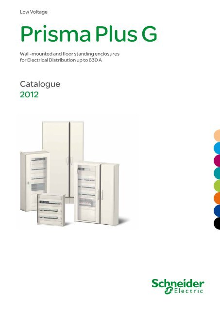
<strong>Prisma</strong> <strong>Plus</strong>:the optimised, tested and IEC compliant solution,for low voltage electrical distribution and control switchboards.<strong>Prisma</strong> <strong>Plus</strong>,a comprehensive range of enclosures and cubicles> A solution based on more than 25 years of experiencein low voltage switchboards.> Integrating <strong>Schneider</strong> <strong>Electric</strong> switchgear offeringsand ensuring electrical, mechanical and communicationfunctions complete consistency.> Quality production, certified ISO 9001.11
PresentationOverviewG System> Schools> Hotels, etc.Pack160 A> Small companies> Buildings> Offices> Residential> Laboratories> Healthcare centres> Shopping centres> Supermarkets> Malls, etc.12
P System3200 A630 A> Hospitals> Bottling factories> Packaging factories> Automobile factories> Food industry> Deary> Internet data centres> Logistics centres, etc.<strong>Prisma</strong> <strong>Plus</strong> P<strong>Prisma</strong> <strong>Plus</strong> G13
PresentationOverviewSimple, functional systems for safe,up to 630 ASwitchboardsthat are safe…With <strong>Prisma</strong> <strong>Plus</strong> G you can be sure to build100 % <strong>Schneider</strong> <strong>Electric</strong> switchboardsthat are safe, optimised:> All components (switchgear, distributionblocks, prefabricated connections, etc.)are perfectly rated and coordinatedto work together;> All switchboard confi gurations, even the mostdemanding ones, have been tested.You can prove that your switchboard meetsthe current standards, at any time.You can be sure to build a reliable electricalinstallation and give your customers fullsatisfaction in terms of dependability and safetyfor people and the installation.…aesthetics<strong>Prisma</strong> <strong>Plus</strong> G with its discreet design,blends harmoniously into all tertiary andindustrial buildings, including in entrancehalls and passageways.Available powerSafety of peopleand propertyControlled costsand delivery timesUpgradeability14
upgradeable LV switchboards…optimised and upgradeableWith <strong>Prisma</strong> <strong>Plus</strong> G you can build just the right switchboard for your customer, sized preciselyto fit costs and needs. With this complete, prefabricated and tested system, it's easy to upgradeyour installation and still maintain the performance levels.> The wall-mounted and floor-standing enclosures combine easily with switchboardsalready in service.> Devices can be replaced or added at any time.Simple movesfor cabling inthe workshopEfficientinstallation andconnectionwork on siteEasymaintenancethroughout theswitchboardAll connection points are fullyaccessible and easy to check.Easy connection on site,whatever the cablecross-section orinstallation location.Easy and direct accessto devices, in a switchboardin service.15
PresentationIEC 61439 standardThe switchboard,central to the electrical installationBoth the point of arrival of energy and a device for distributionto the site applications, the LV switchboard is the intelligenceof the system, central to the electrical installation.It plays an essential role in the availability of electric power, while meeting the needs of personal and property safety.Its definition, design and installation are based on precise rules; there is no place for improvisation. The IEC 61439 standardaims to better define "low-voltage switchgear and controlgear assemblies", ensuring that the specified performances arereached. It specifies in particular:> the responsibilities of each player, distinguishing those of the original equipment manufacturer; the organizationthat performed the original design and associated verification of an assembly in accordance with the standard,and of the assembly manufacturer - the organization taking responsibility for the finished assembly;> the design and verification rules, constituting a benchmark for product certification.All the component parts of the electrical switchboard are concerned by the IEC 61439 standard. Equipment producedin accordance with the requirements of this switchboard standard ensures the safety and reliability of the installation.A switchboard must comply with theequirements of standard IEC 61439-1 and 2to guarantee the safety and reliability of theinstallation. Managers of installations, fullyaware of the professional and legal liabilitiesweighing on their company and on themselves,demand a high level of safety for the electricalinstallation.What is more, the serious economicconsequences of prolonged halts in productionmean that the electrical switchboard mustprovide excellent continuity of service, whateverthe operating conditions.The <strong>Schneider</strong> <strong>Electric</strong> solution> Specify switchboards that comply withstandard IEC 61439-1 and 2.> guarantee a level of safety that has been100 % tested, from the day the switchboardis installed and throughout its service life.> ensure a lasting investment through easyupgrading of the installation in compliancewith the standard.> guarantee that the switchboard complieswith the technical specifications.<strong>Prisma</strong> <strong>Plus</strong> tested switchboardsThe conformity of the switchboard has been testedand proven.A <strong>Prisma</strong> <strong>Plus</strong> switchboard is:> made up of <strong>Schneider</strong> <strong>Electric</strong> low-voltage devices andcomponents that all comply with the applicable standards;> based on configurations in our catalogue;> made up of <strong>Prisma</strong> <strong>Plus</strong> mechanical and electricalcomponents that have been subjected to the verificationof original equipment manufacturer;> mounted and wired by a panelbuilder in compliancewith professional standards;> subjected to the individual verification.<strong>Schneider</strong> <strong>Electric</strong> makes available to the panelbuildereverything required to create tested <strong>Prisma</strong> <strong>Plus</strong>switchboards, including the basic configurations inthe low voltage distribution catalogue, all the documentationfor switchboard design and mounting, calculation anddesign software, etc.Panelbuilders can demonstrate conformity with standardIEC 61439-1 and 2 by presenting the declarations orcertificates of conformity for type tests carried out byindependent laboratories (ASEFA, ASTA, KEMA, etc.)and supplied by <strong>Schneider</strong> <strong>Electric</strong>. The panelbuilderis responsible for the individual routine verification anddelivers the corresponding declarations of conformity.16
Original Manufacturer and Assembly Manufacturer:Both involvedin tested assembliesStandard IEC 61439 clearly definesthe type of verifications that must be conductedby both organisations involved in final conformity ofthe solution: the Original Manufacturer, guaranteeingassembly system design and the AssemblyManufacturer, responsible for the final conformityof the switchboard.Project specification*Specifier> Specifies the needs andconstraints for design,installation, operation andupgrading of the completesystem.> Checks that itsrequirements have been fullyintegrated by the AssemblyManufacturer. Depending onthe application, the specifiercould be the end-user or adesign office.OriginalManufacturerThe organisation that hascarried out the originaldesign and the associatedverification of an assemblysystem.Assembly SystemAssemblyManufacturer(Panel builder)The organisation (whetheror not the same as the OM)responsible for thecompleted assembly.He is responsible for"Routine verifications"on each panel produced,according to the standard.If he derivates from theinstructions of the originalmanufacturer he has to carryout again design verifications.Tested AssemblyEnd-UserShould ask for a certifiedLV switchboard.By systematically requestingroutine verifications,he ensures that the assemblysystem used is compliant.He is responsible for the"Design verifications" listed byIEC 61439-2 including manyelectrical tests.* <strong>Schneider</strong> <strong>Electric</strong> has developeda specification guide.17
PresentationIEC 61439 standardThe main 10 functionsof standard IEC 61439For each of the following 10 functions, the standard IEC 61439 requires designverifications from the system manufacturer - mainly through type-tests - androutine verifications on each panel from the Panel Builder to achieve 3 basic goals:safety, continuity of service and compliance with end-user requirements.SafetyVoltage stresses withstand capabilityTo withstand long term voltages, and transient and temporary overvoltages according to the insulation coordination principlesand requirements.Current-carrying capabilityTo protect against burns and to withstand temperature rise:> when any circuit is continuously loaded, alone, to the specified current> when the assembly is loaded to the specified current according to the specified load pattern (between circuits and/or asa function of the time).Short-circuit withstand capabilityTo withstand the stresses resulting from the prospective short-circuit current and from the associated data (High forces betweenconductors, temp. rise in a very short time, air ionization, overpressure).Protection against electric shock> Hazardous-live-parts not to be accessible (basic protection)> Accessible conductive parts not to become hazardous-live (fault protection).Protection against risk of fire or explosion> Resistance to internal glowing elements> Note: Protection of persons, and optional protection of the assembly, against arcing due to internal fault can be specifiedthrough a "special test" according to IEC 61641.Continuity of serviceMaintenance and modification capabilityCapability to preserve continuity of supply without impairing safety during assembly maintenance or modification> <strong>Electric</strong>al condition of the assembly or various circuits> Speed of exchange of the functional units> Test facilities…Electro-Magnetic compatibilityTo properly function (immunity) and not to generate EM disturbances (emission) in specified environmental conditions:> Industrial networks or locations (Environment A)> Domestic, commercial, and light industrial locations (Environment B).Compliance with end-user requirementsCapability to operate the electrical installationTo properly function, according to:> The electrical diagram of the overall system and related information (voltages, coordination…)> The specified operating facilities (e.g. free or restricted access to Man Machine Interfaces, isolation of the outgoing circuits…).Capability to be installed on site> To withstand handling, transport, storage… and installation constraints> Capability to be erected and connected (type of enclosure, type, material and cross sectional areas of external conductors).Protection of the assembly against mechanical and atmospheric environmental conditions> Presence of water or solid foreign bodies (IP according to IEC 60529)> External mechanical impacts (optional IK according to IEC 62262)> Indoor or outdoor installation (humidity, UV).18
IEC 61 439-1 paragraph 11.4Protection against electric shocksand integrity of protection circuitsThe following should be checked visually:> Presence of protective shields againstdirect and indirect contacts on live parts;> Presence of the PE conductor.The continuity of protection circuits isensured by compliance with the assemblyinstructions delivered with each product.IEC 61 439-1 paragraph 11.5Integration of incorporatedcomponentsThe assembly manufacturer must complywith the instructions of the originalequipment manufacturer for installationand wiring of the components used.IEC 61 439-1 paragraph 11.6Internal electric circuitsand connections<strong>Schneider</strong> <strong>Electric</strong> recommends markingthe nut with a tinted acrylic lacquer, indelibleand temperature-resistant.This allows:> not only self-checking to check effectivetightening to torque;> but also identification of any loosening.IEC 61 439-1 paragraphe 11.9Dielectric propertiesThe main circuits, and the auxiliary andcontrol circuits connected to the main circuit,shall be subjected to the test voltage inaccordance.IEC 61 439-1 paragraph 11.10Wiring, operating performanceand functionVerification of wiring and marking conformitywith the drawings, parts list and diagram.Standard individualcheck sheetin accordance with the IEC 61439-1and 2 standard from the assemblymanufacturer (panelbuilder)Job No.: .................................................................................................Switchboard No.: ...................................................................................Drawing No./Rev. No.: ............................................................................Degrees of protection provided by enclosures 11.2Insulation clearances and creepage distances 11.3Protection against electric shocks and integrityof protection circuitsChapter11.4Integration of incorporated components 11.5Internal electric circuits and connections 11.6Terminals for external conductors 11.7Mechanical operation 11.8Dielectric properties 11.9Wiring, operating performance and function 11.10Date of verification:............ / ............ /.............Verifications performed by:Verified..........................................................................…………………………19
PresentationExamples of switchboardconfigurationsIncomerCompact NSX250 4PFixed, front connectionToggleIncoming cables via bottomto incoming connection blockPD390891_SEDistributionPolybloc distribution blockOutgoing devicesMulti 9 or Acti 9 devicesSupplyCable runningConnectionMotor circuit breakersSupplyCable runningConnection80 A MulticlipComb busbarsStraps + coverTerminal block at topof switchboardComb busbarsStraps + coverTerminal block at topof switchboardIP30 enclosureWall-mounted enclosure, W = 595 mm, H = 930 mmPlain doorPartial plain doorPD390287_SE20
PresentationExamples of switchboardconfigurationsIncomerInterpact INS160 4PIncoming cables via topPD390446R_SEDistribution160 A Powerclip busbarsOutgoing devicesMulti 9 or Acti 9 devicesSupply80 A MulticlipComb busbarsCable runningStraps + coverConnectionTerminal block in duct,W = 300 mmMotor circuit breaker + contactor combinationsSupplyCable wiringCable runningStraps + coverConnectionTerminal block in duct,W = 300 mmIP30 enclosureWall-mounted enclosure,W = 595 mm, H = 1230 mmTransparent doorDuct, W = 305 mm,H = 1230 mmPlain doorPD395007_SE21
PresentationExamples of switchboardconfigurationsIncomerCompact NSX250Fixed, front connectionToggleIncoming cables via top to incoming connection blockPD390288_SEDistributionPowerclip busbarsOutgoing devicesMulti 9 or Acti 9 devicesSupplyCable runningConnectionMotor circuit breakersSupplyCable runningConnection80/200 A MulticlipComb busbarsStraps + coverTrunkingTerminal block in duct,W = 300 mmCable wiringTrunkingTerminal block in duct,W = 300 mmIP30 enclosureWall-mounted enclosure, Transparent doorW = 595 mm, H = 1230 mmDuct, W = 305 mm, Plain doorH = 1230 mmPD390289_SE22
PresentationExamples of switchboardconfigurationsIncomerInterpact INS160Lateral handleIncoming cables via bottom, directly to devicePD390450R_SEDistributionDistribloc distribution blockOutgoing devicesMulti 9 or Acti 9 devicesSupplyComb busbarsCable runningCable running Straps + coverConnectionTerminal block at bottomof enclosureMotor control and protection devicesSupplyComb busbarsCable runningTrunkingConnectionTerminal block at bottomof enclosureIP55 enclosureWall-mounted enclosure, Transparent doorW = 595 mm, H = 1250 mmPB11000323
PresentationExamples of switchboardconfigurationsIncomerCompact NSX400Fixed, front connectionToggleIncoming cables via bottom in duct (W = 300 mm) to incomingconnection blockDistributionPowerclip busbarsOutgoing devicesCompact NSX250Fixed, front connectionToggleSupplyMulti 9 or Acti 9 devicesSupplyPowerclip busbars with powersupply blockComb busbars200 A MulticlipTrunkingCable runningConnectionVertical terminal block at bottomof floor-standing enclosureAppareils protection et commande moteurSupplyCable runningConnectionMulticlip 200 ATrunkingVertical terminal block at bottomof floor-standing enclosureEnveloppe IP30Floor-standing enclosure, Transparent doorW = 595 mm, H = 1830 mmDuct, W = 305 mm, Plain doorH = 1830 mmPD390893_SE PD395034_SE24
PresentationDetermining catalogue numbersRapsody softwareEasy designwith RapsodysoftwareA time-saver inthe design andquotation phases.More flexibility sincemodifications andupgrades arepossible throughoutthe project.5easy steps to design a switchboardDefine the switchboard'selectrical and environmentalcharacteristics,in a few clicks.Choose and configurethe devices to be installed,with no risk of error.Customise, and easily modifythe single-line diagram.Move or duplicate devices.Generate current distributionand connection systems.Choose the switchboardand let the software set upthe enclosure.A list of mounting and connectionaccessories is proposed to makemounting work easier.Automatically exportthe information required tomake a clear, comprehensiveand professional quotation.25
PresentationDetermining catalogue numbersStarting with the electricaldiagram: IP30 switchboardDD384078NSX250C60ouIC60C60ouIC60C60ouIC60DD381888Install the incomer> see page 32bborder the mountingplates and the front platesbbthe incomingconnection blockbbthe power supply blockfor the Powerclip busbars.1DD383850Installation/connectionDD383960NSXNSX100/250 032322DD381878Distribution usingPowerclip busbarsDD383961NSX100/250NSXNSXDD383521Multi 9 or Acti 9Install the modular devices 1Order the mountingplates and front platestaking into account:bbsupply to the rowsbbcable running.DD383518> see page 47DD384084All Multi 9 or Acti 9 devicesMulti 9 or Acti 9 devices y 40 ADD383519DD384085All Multi 9 or Acti 9 devicesMulti 9 or Acti 9 devices y 40 A2TeSys "U"> see page 49DD381978DD381880bbMulticlip distribution block > see page 80bbcable running > see page 60Determine the size of the switchboard19 modulesbbcount the numberof occupied modulesbbdetermine thecorrespondingwall-mount enclosurebborder the additionalplain front plate.21 modulesPlain front plate> see page 56DD38197926
PresentationDetermining catalogue numbersDD383522Plan the distribution systemDD381882Powerclip busbars> see page 68DD384355DD383523Select the terminal blocks and the earth bar> see page 84DD383520DD384356Select the enclosures> see page 89 IP wall-mount enclosureDD381892DD3818841DD381982Wall-mount enclosure (IP30)2DD381885Duct, W = 300 mmDD3819833Cable tie supportsDD3819854Accessories forlifting, handling,wall mounting, finishingparts, etc.27
Functionalsystem28
Functional systemContentsPresentation..................................................................................30Functional units and distribution............................32Circuit breakers .............................................................................32Compact NSX 100/250 horizontal mounting........................................................ 32Compact NSX 100/250 vertical mounting............................................................ 33Compact NSX 400/630 horizontal mounting........................................................ 34Compact NSX 400/630 vertical mounting............................................................ 35Easypact EZC100/400 horizontal mounting......................................................... 36Easypact EZC100/400 vertical mounting............................................................. 37Switch-disconnectors ....................................................................38Interpact INS-INV250/630 horizontal mounting.................................................... 38Interpact INS-INV250/630 vertical mounting........................................................ 39Manual source changeover system ..............................................40Compact NSX 100/250 changeover system........................................................ 40Interpact INS-INV250 changeover system........................................................... 41Fusegear ......................................................................................42Fupact INF horizontal mounting........................................................................... 42Fupact INF vertical mounting............................................................................... 43Fupact ISFT and ISFT-N horizontal mounting...................................................... 44Fupact ISFT and ISFT-N vertical mounting.......................................................... 45Modular devices............................................................................46Modular devices 80/160 A switchboard incomer.................................................. 46Modular devices outgoers y 63 A.......................................................................... 47Industrial control devices ..............................................................48TeSys, Altistart, Phaseo....................................................................................... 48Other devices................................................................................50Kilowatt-hour meters Classe II............................................................................. 50Kilowatt-hour meters............................................................................................ 51Human-switchboard interface.............................................................................. 52Accessories.................................................................. 56Front plates, rails, slotted mounting plates........................................................... 56Fixing accessories............................................................................................... 58Partitioning........................................................................................................... 59Cable running...................................................................................................... 60Switchboard lighting............................................................................................. 62Finishing parts..................................................................................................... 63Management of the internal temperature............................................................. 64Distribution.................................................................. 66Panorama of the solution..................................................................................... 66Non-Centralised distribution..........................................................68630 A insulated busbar......................................................................................... 68400 A rear busbars............................................................................................... 70630 A multi-stage busbars in duct......................................................................... 72Insulated flexible bars.......................................................................................... 74Centralised distribution..................................................................75Distribution block ................................................................................................. 75Comb busbars..................................................................................................... 82Earth block / neutral block.................................................................................... 83Earth bars............................................................................................................ 84Terminal blocks.................................................................................................... 86Terminal blocks layout.......................................................................................... 8729
Functional systemPresentationReadily availableclose byThe kit concept makes handling and transporteasier and you get to benefit from <strong>Schneider</strong> <strong>Electric</strong>’sefficient international logistics. Your distributor,hand-picked by <strong>Schneider</strong> <strong>Electric</strong>, can give youthe very best advice. For determining cataloguenumbers, > see page 25.Straightforward organisationto make your job easier> Clearly identified functions.The switchboard is set up in different functional units, organised naturally.MountingplateCompact NSX 160Terminal blockBusbar powerconnectionFront plateExample: "Incomer" functional unit.> A switchboard with a high degree of legibility.The easy-to-read switchboard circuit diagram makeson-site cabling and connection operations simple.30
Functional systemPresentationThe <strong>Prisma</strong> <strong>Plus</strong> functional systemThe <strong>Prisma</strong> <strong>Plus</strong> functional system can be used for all types of low-voltagedistribution switchboards up to 630 A, in commercial and industrial environments.Switchboard design is very simple.A functional structure for devicesmade up of wall-mounted and floor-standing enclosures that can be used alone orcombined.A distribution systemmade up of Centralised distribution blocks and vertical busbars installed on the sideor in the rear of the switchboard.Complete functional unitsEach device is part of a functional unit comprising:bba dedicated mounting plate for device installationbba front plate to block direct access to live partsbbprefabricated busbar connectionsbbsystems for on-site connections and running of auxiliary wires.The functional units are modular and are arranged rationally, one on top of another,within the enclosure.The system includes everything required for functional unit mounting, supply andonsiteconnection.The components of the <strong>Prisma</strong> <strong>Plus</strong> system and those of the functional units inparticular have been designed and tested taking into account device characteristics.This design approach ensures a high degree of reliability in system operation andoptimum safety for personnel.<strong>Electric</strong>al characteristics<strong>Prisma</strong> <strong>Plus</strong> components comply with standard IEC 61439-1 et 2 and havethe following electrical characteristics:bbrated insulation level of main busbars at rear of enclosure: 1000 Vbbrated operational current Ie (40 °C): 630 Abbrated peak withstand current Ipk: 53 kÂbbrated short-time withstand current Icw: 25 kA rms / 1 secondbbfrequency: 50/60 Hz.31
Functional systemFunctional unitsand distributionCircuit breakersCompact NSX 100/250horizontal mountingMounting Horizontal fixed (1)600 300Devices Toggle Direct rotary handle Motor mechanismmoduleNSX100/250 Vigi NSX100/250 NSX100/250 Vigi NSX100/250 NSX100/250Number of devices per row 1 1 1 1 1No. of vertical modules 5 6 8 8 8Mounting plates 03030 03033 03031 03031 03032Front plates[No. of verticalmodules]with cut-out 03232 [4] 03292 [4] 03232 [4] 03292 [4] + LV429285 (sas) 03234 [4]upstream 03801 [1] 03802 [2] 03802 [2] 03802 [2] 03802 [2]downstream - - 03802 [2] 03802 [2] 03802 [2]Incoming connection block cables via top: 04066 - - - -cables via bottom: 04067Long terminal shields - 3P: LV4295174P: LV4295183P: LV4295174P: LV4295183P: LV4295174P: LV4295183P: LV4295174P: LV429518+ cable tying - 08867 -(1) Maximum size of connection cables: 70 mm². For cable cross-sections greater than 70 mm², use of a cable duct is recommended.Mounting Horizontal fixed Horizontal plug-in600 300Devices Toggle Direct rotary handle Motor TogglemechanismmoduleNSX100/250 NSX100/250 NSX100/250 Vigi NSX100/250 NSX100/250 NSX100/250with ammetermodule or VigiNumber of devices per row 1 1 1 1 1 1No. of vertical modules 4 4 6 6 6 4Mounting plates 03030 03033 03031 03031 03032 03032Front plates with cut-out 03232 [4] 03292 [4] 03232 [4] 03292 [4]03234 [4] 03290 [4][No. of verticalmodules] downstream - - 03802 [2]+ LV429285 (sas)03802 [2] 03802 [2] -Long terminal shields3P: LV4295174P: LV4295183P: LV4295174P: LV429518+ adaptator - 3P: LV4293064P: LV429307DistributionPolybloc distributionblockPowerclip busbars Rear busbars Busbars in ductDD380587DD380522DD380777DD380761DD383855DD380589DD383855DD383856DD380594Type of connected All type Toggle Direct rotary handle or All typeAll typedevicesNSX NSX with ammeter moduleor Vigi NSXmotor mechanism moduleBusbars /3P: 04033 > see page 75 > see page 68 > see page 70 > see page 72distribution blocks 4P: 04034Power supply block - 04060 (2) 04060 (2) 04061 (3)Short terminal shield - - 3P: LV429515-4P: LV429516(2) Supplied with connections - (3) Connection must be made.32
Functional systemFunctional unitsand distributionCircuit breakersCompact NSX 100/250vertical mountingMountingVertical fixed600 300Devices Toggle Direct rotary handleNSX100/160 NSX250 Vigi NSX100/160 Vigi NSX250 NSX100/160 NSX250 Vigi NSX100/160 Vigi NSX250Number of devices per row 4 x 3P or 3 x 4P 4 x 3P or 3 x 4PNo. of vertical modules (1) 7 9 8 11 7 9 8 11Mounting plates 03040 03040 03040 03040 03041 03041 03041 03041Front plates[No. of verticalwith cut-out 03243 [5] 03243 [5] 03241 [7] 03241 [7] 03243 [5] 03243 [5] 03244 [7]+ LV429285 (sas)03244 [7]+ LV429285 (sas)modules] upstream - 03802 [2] - 03802 [2] - 03802 [2] - 03802 [2]downstream 03802 [2] 03802 [2] 03801 [1] 03802 [2] 03802 [2] 03802 [2] 03801 [1] 03802 [2]Incoming connection block 3P: LV4295174P: LV429518Divisible 85 x 147 mm 03249 (to add modular devices to a row with Compact NSX 3P or 4P without electronic trip unit)blanking plates 107 x 147 mm 03222 (to add modular devices to a row with Compact NSX 3P or 4P with electronic trip unit)(1) With or without spreaders, whatever the distribution solution.Distribution Polybloc distribution block Powerclip busbars Rear busbars Busbars in ductType of connected devices All type NSX Vigi NSX All type All typeDistribution block / busbars 3P: 04033 > see page 75 > see page 68 > see page 70 > see page 724P: 04034Adjustable rail 03002 -Power supply block - 04061Connection block - 04062 must be madeShort terminal shield - 3P: LV4295154P: LV429516Mounting300 600Vertical fixedDD383858Distribution Polyblocdistributionblock in ductBusbarsPowerclip (3)Multi-stage busbarsor multi-stagedistribution block inductRear busbarsDD380745DD382567DD382305DD380777DD380780DD380593DD380777DD380761DD383871DD380666Devices Toggle Direct rotaryhandleNSX100/250Vigi NSX100/250NSX100/250Number of devices 1 1 1per rowNo. of vertical 9 11 9modules (2)Mounting plates 03050 03050 03051Cut-out front plates 03253 03293 03253Incomingconnection block3P: LV4295174P: LV429518(2) With or without spreaders.Type ofconnecteddevicesDistributionblock /busbarsAll type NSX Vigi NSX All type All type3P: 040334P: 04034> see page 75> see page 68 > see page 72 > see page 70Adjustable rail 03011 - -Power supply - 04061 -blockConnection - 04062 must be 04065blockmadeShort terminal - 3P: LV429515 -shield4P: LV429516(3) Space available at the top of the enclosure after mounting the universal power supplyblock:- NSX 100/250 = 7 modules- Vigi NSX 100/250 = 9 modules.Space required by power supply block on Powerclip busbars = 5 modules.33
Functional systemFunctional unitsand distributionCircuit breakersCompact NSX 400/630horizontal mountingMountingHorizontal fixed600 300DevicesToggleNSX400/630Number of devices per row 1 1No. of vertical modules 9 6Mounting plates 03070 03070Front plates cut-out 03296 [6] 03296 [6][No. of vertical upstream 03803 [3] -modules]Incoming connection block 04076 04076Distribution Powerclip busbars Rear busbars Busbars in ductDD380783DD380777DD380761DD383852DD383851Type of connected devices NSX400 NSX630 All type All typeBusbars > see page 68 > see page 70 > see page 72Power supply block 04070 04071 - -34
Functional systemFunctional unitsand distributionCircuit breakersCompact NSX 400/630vertical mountingMountingVertical fixed600 300Devices Toggle Direct rotary handleNSX400 NSX630 Vigi NSX400 Vigi NSX630 NSX400/630 Vigi NSX400/630Number of devices per row 1 1 1 1 1 1No. of vertical modules (1) 11 12 13 14 14 17Mounting plates 03073 03073 03073 03073 03074 03074Front plates[No. of verticalcut-out 03275 [9] 03275 [9] 03297 [11] 03297 [11] 03275 [9] 03297 [11]+ LV429285 (sas)modules] upstream 03802 [2] 03802 [2] 03802 [2] 03802 [2] 03802 [2] 03802 [2]downstream - 03801 [1] - 03801 [1] 03803 [3] 03804 [4]Long terminal shield3P: LV4325934P: LV432594(1) With or without spreaders.Distribution Powerclip busbars Rear busbars Busbars in ductDD383825DD380777DD380761DD383853DD383854Type of connected devices All type All type All typeBusbars > see page 68 > see page 70 > see page 72Power supply block 04074 (2)Short terminal shield3P: LV4295154P: LV429516(2) Connection must be madeMounting300 600Vertical fixedDD383857DD383858BusbarsPowerclip (4) Multi-spacein ductDd382567Dd382305RearDD380777Devices Toggle Direct rotary handleNSX400 NSX630 Vigi NSX400/630NSX400/630Number of devices 1 1 1 1per rowNo. of vertical modules (3) 11 12 14Mounting plates 03080 03080 03080 03081Front cut-out 03298 [8] 03298 [8] 03299 03283 [12]plates[No. of upstream 03812 [2] 03812 [2][10]03812 [2] -verticalmodules]downstream 03811 [1] 03812 [2] 03812 [2] -Long terminal shield 3P: LV4325934P: LV432594(3) With or without spreadersType of All type All type All typeconnecteddevicesBusbars > see page 68 > see page 70 > see page 72Power supply 04074 - -blockConnection 04073 04075 -blockShort terminal 3P: LV432591-shield 4P: LV432592Barrier included 04197 04198(4) Space available at the top of the enclosure after mountingthe universal power supply block:- NSX 100/250 = 7 modules- Vigi NSX 100/250 = 9 modulesSpace required by power supply block on Powerclip busbars= 5 modules.35
Functional systemFunctional unitsand distributionCircuit breakersEasypact EZC100/400horizontal mountingMountingHorizontal fixed600 300DevicesToggleEZC250 / EZCV250EZC4003P 4P 3P 4PNumber of devices per row 1 1 1 1No. of vertical modules 4 4 5 5Mounting plates 03104 03104 03105 03105Cut-out front plates 03304 03304 03306 03306Long terminal shield (set of 2) EZETSHD3P EZETSHD4P EZ4TSHD3P EZ4TSHD4PDistribution Rear busbars Busbars in ductDD380777DD380761DD383994Type of connected devices All type All typeBusbars / distribution block > see page 70 > see page 7236
Functional systemFunctional unitsand distributionCircuit breakersEasypact EZC100/400vertical mountingMountingVertical fixed600 300DevicesToggleEZC100 EZC250 / EZCV250 EZC4001P 3P 4P 3P 4P 3P 4PNumber of devices per row 15 5 3 4 3 1 1No. of vertical modules 5 5 5 7 7 10 10Mounting plates 03102 03102 03102 03104 03104 03105 03105Cut-out front plates 03303 03303 03303 03305 03305 03307 03307Long terminal shield (set of 2) - EZATSHD3P EZATSHD4P EZETSHD3PN EZETSHD4PN EZ4TSHD3P EZ4TSHD4PDivisible blanking plateH = 85 mm, L = 147 mm03249 -Distribution Polybloc distribution block Rear busbars Busbars in ductDD383493DD380777DD380761DD38110DD383044DD383993Type of connected devices EZC100 All type All typeBusbars / distribution block 04031 (x no. of pole) > see page 70 > see page 72Fixed rail 0300137
Functional systemFunctional unitsand distributionSwitch-disconnectorsInterpact INS-INV250/630horizontal mountingMountingHorizontal fixed with connection block600 300DevicesDirect front handleINS-INV250Number of devices per row 1No. of vertical modules 5Mounting plates 03030Front plates[No. of verticalmodules]Incomingconnectionblockcut-out 03231 [4]upstream 03801 [1]cables via top 04066cables via top 04067MountingHorizontal fixed, direct connection600 300DevicesDirect front handleINS-INV250 INS-INV320/630 INS-INV320/630Number of devices per row 1 1 1No. of vertical modules 4 9 6Mounting plates 03030 03070 03070Front plates cut-out 03231 [4] 03271 [6] 03271 [6][No. of verticalmodules]upstream - 03803 [3] -Long terminal shield (set of 2) 29324 32565 32565Distribution Polybloc distribution block Powerclip busbars Rear busbars Busbars in ductDd381346Dd381349DD380777DD380761DD380670DD380669Type of connected devices INS-INV250 INS-INV INS-INV INS-INV All typeAll type250 320/400 500/6303P4PDistribution block / busbars 04033 04034 > see page 68 > see page 70 > see page 72Power supply block (1) - 04060 04070 04071(1) Supplied with connection38
Functional systemFunctional unitsand distributionSwitch-disconnectorsInterpact INS-INV250/630vertical mountingMountingVertical fixed with or without spreaders600 300Devices Direct front handle Lateral handleINS/INV250 INS/INV320/400 INS/INV500/630 INS/INV250Number of devices per row 1 1 1 1No. of vertical modules 8 10 12 8Mounting plates 03040 03073 03073 03032Front plates cut-out 03248 [5] 03274 [10] 03274 [10] -[No. of vertical upstream 03801 [1] - 03802 [2] 03806 [6]modules] downstream 03802 [2] - - 03802 [2]Long terminal shield (set of 2) 29324 32565 32565 29324Distribution Polybloc distribution block Powerclip busbars Rear busbars Busbars in ductDd381347Dd381348DD380777DD380761Dd380761Type of connected devices INS-NV250 INS-INV INS-INV All typeAll type250320/630Front handleLateral handle3P 4P 3P 4PDistribution block / busbars 04033 04034 04033 04034 > see page 68 > see page 70 > see page 72+ 04037 (1) + 04037 (1)Adjustable modular device rail 03002 03002 03003 03003 - -Power supply block - 04060 04074Connection block - 04062 must be madeShort terminal shield - 29322 32563(1) Copper spacer.Mounting300 600Vertical fixed with orwithout spreadersDD80773DistributionPolyblocdistributionblockDD382569Powerclipbusbars (2)DD382570Multi-stagebusbarsin a ductDD382571Rear busbarsDD380777DevicesFront direct rotary handleINS-INV250INS-INV320/400INS-INV500/630Number of devices 1 1 1per rowNo. of vertical modules 9 10 12Mounting plates 03050 03080 03080Front plates cut-out 03251 [9] 03281 [10] 03281 [10][No. of downstream - - 03812 [2]verticalmodules]Long terminal shield(set of 2)29324 32565 32565Type ofconnecteddevicesDistributionblocks /BusbarsAdjustablemodular devicerailPower supplyblockConnectionblockShort terminalshieldINS-INV250INS-INV250INS-INV320/630INS-INV250INS-INV320/630All type3P 4P04033 04034 > see page 68 > see page 70 > see page 7203011 - - -- 04061 04074 - -- 04064 04073 04065 04075 -- 29322 32563 29322 32563 -Barrier - included 04197 04198(2) Space available at the top of the enclosure after mounting the universal power supply block:7 modules. Encombrement du bloc d’alimentation sur Powerclip: 5 modules39
esetOOO FONIFunctional systemFunctional unitsand distributionManual source changeover systemCompact NSX 100/250circuit breakerchangeover systemMountingFixed(changeover with mechanical interlocking)600 300DD380535DevicesFront connection, direct rotary handleNSX100/2503P4PNo. of vertical modules 10 10Mounting plates 03043 03043Front plates cut-out 03245 [5] 03245 [5][No. of vertical upstream 03802 [2] 03802 [2]modules] downstream 03803 [3] 03803 [3]Mechanical interlocking LV429369 LV429369Long terminal shield LV429517 LV429518Coupling accessory 29358 2935940
OFFOI ONIONFunctional systemFunctional unitsand distributionManual source changeover systemInterpact INS-INV250switch-disconnectorchangeover systemMountingFixed(changeover with mechanical interlocking)Fixed(Complete source changeover assembly)600 300DD380536DD380537Devices Front, direct rotary handle Front, direct rotary handleINS-INV250INS2503P 4P 3P 4PNo. of vertical modules 9 9 9 9Mounting plates 03043 + 2 x 31064 (raiser) 03043 + 2 x 31064 (raiser) 03043 03043Front plates cut-out 03235 [5] 03235 [5] 03247 [5] 03247 [5][No. of vertical upstream 03802 [2] 03802 [2] 03802 [2] 03802 [2]modules] downstream 03802 [2] 03802 [2] 03802 [2] 03802 [2]Mechanical interlocking 31073 31073 - -Complete source changeoverassembly- - 100 A: 31140160 A: 31144200 A: 31142250 A: 31146100 A: 31141160 A: 31145200 A: 31143250 A: 31147Long terminal shield 29324 29324 29324 29324Coupling accessory 29358 29359 29358 2935941
Functional systemFunctional unitsand distributionFusegearFupact INFhorizontal mountingMountingHorizontal600 300DevicesExtended rotary handleINF32 INF40/60 INF100/1603P or 4P 3P 4P 3P 4PNumber of devices per row 1 1 1 1 1No. of vertical modules 3 5 5 7 7Mounting plates 03113 03114 03114 03114 03114Front plates cut-out 03313 03314 03314 03314 [5] 03314 [5][No. of verticalmodules]downstream - - - 03802 [2] (1) 03802 [2] (1)Long terminal shield - 49658 49658 x 2 49659 x 6 49659 x 8(1) Not needed if direct distribution.Distribution Multi-stage busbars in a duct Powerclip busbars (2) Rear busbarsDD383846DD381380DD380777DD382474Dd382475Type of connected devices All type INF100/160 All type3P4PDistribution blocks / busbars > see page 70 > see page 68 > see page 72Additional 35 mm 2 block 04155 04156Connection block must be made must be made(2) The mounting plate for INF Fupact does not leave a passage for the busbar; it can only be installed below the plate.The distribution system is installed under the functional unit.42
Functional systemFunctional unitsand distributionFusegearFupact INFvertical mountingMountingVertical600 300DevicesExtended rotary handleINF32/40 INF63 INF100/1603P 4P 3P 4P 3P 4PNumber of devices per row 4 3 3 2 2 2No. of vertical modules 3 3 5 5 7 7Mounting plates 03113 03113 03114 03114 03114 03114Front plates cut-out 03312 03313 03314 03315 03315 [5] 03315 [5][No. of verticalmodules]downstream - - - - 03802 [2] (1) 03802 [2] (1)Long terminal shield - - 49658 49658 x 2 49659 x 6 49659 x 8(1) Not needed if direct distribution.Distribution Polybloc distribution block Powerclip busbars (2) Rear busbars Busbars in ductDD383658DD381380DD380777DD380761DD382477DD382478Type of connected devices INF100/160 INF100/160 All type All type3P4PDistribution blocks / busbars 04031 x 3 04031 x 4 > see page 70 > see page 68 > see page 72Adjustable modular device rail 03002 03002 -Universal power supply block - - 04061Connection block must be made must be made must be made(2) The mounting plate for INF Fupact does not leave a passage for the busbar; it can only be installed below the plate.The distribution system is installed under the functional unit.43
Functional systemFunctional unitsand distributionFusegearFupact ISFT and ISFT-N, 3Phorizontal mountingMountingHorizontal600 300DevicesOn mounting plateISFT160ISFT250Number of devices per row 1 1No. of vertical modules 6 6Mounting plates 03121 03124Front plates cut-out 03326 [3] 03328 [5][No. of vertical upstream 03801 [1] -modules]downstream 03802 [2] (1) 03801 [1]Long terminal shield 49869 x 2 49872 x 2(1) Not needed if direct distribution.Busbars Powerclip busbars Rear busbars Busbars in ductDd382481Dd380777Dd380761DD342480Type of connected devi ces All type All type All typeDistribution blocks / busbars > see page 68 > see page 70 > see page 72Universal power supply block 04061Connection blockmust be made44
Functional systemFunctional unitsand distributionFusegearFupact ISFT and ISFT-N, 3Pvertical mountingMountingVertical600 300Devices On mounting plate On busbarsISFT100 ISFT100N ISFT160 ISFT100N ISFT160Number of devices 5 8 4 6 4per rowNo. of vertical modules 7 8 8 8 8Mounting plates 03120 03126 03121 03122 03122Front cut-out 03320 [6] 03325 [8] 03321 [6] 03325 [8] 03321 [6]plates upstream - - - - -[No. ofdownstream 03801 [1] - 03802 [2] (1) - 03802 [2] (1)verticalmodules]Long terminal shield - - 49869 x 2 - 49869 x 2(1) Not needed if direct distribution.DistributionComb busbarConnected Type ISFT100devices Number 2 3 4 5Comb busbar 49861 49862 49863 49861+49862Coupler to connect 2 busbars - - - 49890Tooth cover 49864Set of 3 connectors25 to 95 mm 2 49865Distribution Connectors (2) Polybloc distribution block Powerclip busbars Rear busbars Busbars in ductDD382484Type of connected devices ISFT100 All type All type All type All typeConnectors / distribution block / 49860 04031 x 3 > see page 68 > see page 70 > see page 72busbarsAdjustable modular device rail - 03002 -Universal power supply block - - 04061Connection block must be made must be made must be made(2) Set of 3 connectors 3 x 10 mm 2MountingVertical fixed300 600DevicesOn mounting plateISFT160ISFT250Number of devices per row 1 1No. of vertical modules 6 9Mounting plates 03123 03125Cut-out front plates 03327 03329Long terminal shield 49869 x 2 49872 x 2Distribution Polybloc distribution block Powerclip busbars Multi-stage busbars in a duct Rear busbarsDd382843Dd382490DD380777Dd382488DD383659DD382847DD380777DD380761Dd382482Dd382483Type of connected devices ISFT160 All type All type All typeDistribution block / busbars 04031 x 3 > see page 68 > see page 70 > see page 72Adjustable modular device rail 03011 - -Universal power supply block - 04061 -Connection block must be made must be made must be made45
Functional systemFunctional unitsand distributionModular devicesModular devicesoutgoers 63 AMountingHorizontal distancesbetween centres: 200 mmHorizontal distances between centres: 150 mmVertical600 300Devices All modular devices Modular devices 40 A All modulardevicesRail length (modules of 9 mm) 48 48 48 48 64No. of vertical modules 4 (1) 3 8 9 12Rail (48 modules of 9 mm) 03001 03001 03001 x 3 04226 04226Modular front plates 03204 03203 03223 03228 03229Blanking plate> see page 127strip 03220 03220 03220 03220divisible 03221 03221 03221 03221(1) Note: For a modular row with a 160A (half row) and 200 A Multiclip distribution block positioned directly below a non-modular mounting-plate(Compact, Interpact, etc...), or at the top of a switchboard, add one additional module (i.e. 4+1) and a plain upstream front plate(03801)Distances betweenrowsHorizontal distances between centres: 200 mmHorizontal distances between centres: 150 mm300 600Devices All modular devices Modular devices 40 ARail length (modules of 9 mm) 20 20No. of vertical modules 4 3Rail (20 modules of 9 mm) 03010 03010Modular front plates 03214 03213Blanking plate> see page 127strip 03220 03220divisible 03221 03221Distribution Comb busbar Multiclipdistribution blockDd382484DD384088Dd383490Dd383489Dd383264Dd383265Dd383266Dd383121Type of connected devices According devices All typeComb busbars /> see page 82 > see page 80distribution blocks47
Functional systemFunctional unitsand distributionIndustrial control devicesTeSys, Altistart, PhaseoMountingTeSys D, TeSys K contactorsFor 600 mm wide wall-mountedand floor standing enclosuresFor 300 mm wide duct600 300Devices LC1Dp or LC1Kp ( 40 A) LC1Dp or LC1Kp ( 40 A)Useful length for rail 432 mm 180 mmNo. of vertical modules 3 3Rail 03004 (in rear) 03011 (adjustable)Plain front plates 03803 03813MountingTeSys GV2/GV3 circuit breakersFor 600 mm wide wall-mountedand floor standing enclosuresFor 300 mm wide duct600 300Devices TeSys GV2 TeSys GV3 TeSys GV2 TeSys GV3Useful length for rail 432 mm 432 mm 180 mm 180 mmNo. of vertical modules 3 5 3 5Rail 03001 03002 03010 03011 (adjustable)Front plates[No. of verticalmodules]Blanking plate> see page 127cut-out 03203 [3] 03205 [5] 03213 [3] 03213 [3]upstream - - - 03811 [1]downstream - - - 03811 [1]strip 03220 03220 03220 03220divisible 03221 03221 03221 03221MountingCombined TeSys GV2 circuit breaker + contactorFor 600 mm wide wall-mountedand floor standing enclosuresFor 300 mm wide duct600 300DD381318DD381189DD383494DD383492DD381613DD380708Devices GV2 + LC1Dp or LC1Kp ( 40 A) GV2 + LC1Dp or LC1Kp ( 40 A)Useful length for rail 432 mm 180 mmNo. of vertical modules 5 5Rail 03004 (in rear) 03011 (adjustable)Front plates[No. of verticalmodules]transparent 03342 [4] 03352 [4]plain03801 [1] 03811 [1]downstream48
Functional systemFunctional unitsand distributionIndustrial control devicesTeSys, Altistart, PhaseoMountingTesys U starter-controlerFor 600 mm wide wall-mountedand floor standing enclosuresFor 300 mm wide duct600 300Devices TeSys U TeSys U (1) TeSys U TeSys U (1)Useful length for rail 432 mm 432 mm 180 mm 180 mmNo. of vertical modules 5 4 5 4Rail 03004 (in rear) 03004 (in rear) 03011 (adjustable) 03011 (adjustable)Front plates[No. of verticalmodules]transparent 03342 [4] (2) 03342 [4] (3) 03352 [4] (2) 03352 [4] (3)plain 03801 [1] - 03811 [1] -(1) TeSys U without communication module, neither auxiliary contact, neither inverter module.(2) If the communication module is installed, the transparent front plate is mandatory. If not, the 2 front plates can be replaced byone plain front plate (cat.no 03805 in wall-mounted or floor-standing enclosure, 03815 in duct).(3) Or plain front plate (cat.no 03804 in wall-mounted or floor-standing enclosure, 03814 in duct).Soft starters Altistart 01Mounting On rail in the enclosure (L = 600 mm) On recessed slottedmounting plate (L = 600 mm)On rail in duct(L = 300 mm)600 300DevicesATS01N103FT ATS01N109FT ATS01N222ATS01N106FT ATS01N112FT to 232ATS01N206to 212ATS01N230LY ATS01N272LY, ATS01N285LYATS01N244LY ATS01N272Q, ATS01N285QATS01N244QATS01N103FTATS01N106FTNumber of devices per row 19 9 9 2 2 19Useful length 432 mm 432 mm 432 mm 432 mm 420 mm 180 mmNo. of vertical modules 4 5 6 5 6 4Rail 03004 03003 03003 03003 - 03011 (adjustable)(in rear)Slotted plates - - - - 03172 -Plain front plates 03804 03805 03806 03805 03806 03814MountingSupply and LV/LV Phaseo transformerOn recessed slottedmounting plate (L = 600 mm)On a slotted plate(L = 300 mm)600 300DD382816DD380709DD382603DD382604DD381191DD381319DD381190Devices ABL6TS/TD, ABL6-RF ABL6TS/TD, ABL6-RFUseful length for mounting plate 420 mm 172 mmNo. of vertical modules 4 4Slotted plates 03171 03175Plain front plates 03804 0381449
Functional systemFunctional unitsand distributionOther devicesKilowatt-hour metersClasse IIMounting Accessible (1)600 300Devices Single-phase (Ph + N) 3-phase (3 Ph + N)Number of devices per row 3 2No. of vertical modules 6 9Mounting plates 03157 03152Metering front plates 03155 03158Horizontal partitioning 04331 04331Insulating plate 03154 03154Accessories M5 spacers for mounting plate > see page 58Mounting Behind front plate (1)600 300DD382950DD382951DD382948DD382949Devices Single-phase (Ph + N) 3-phase (3 Ph + N)Number of devices per row 3 2No. of vertical modules 6 9Mounting plates 03157 03152Front plate atyour choicetransparent 03343 03344plain 03806 03807Horizontal partitioning 04331 04331Insulating plates 03154 03154Accessories M5 spacers for mounting plate > see page 58(1) Order one additional horizontal partition in case of installation other than at the top of enclosure.Note: Meters can be installed directly on mounting plate equipped with 6 mm² earthing braid (cat.no 08910) and combinedwith partitioning or front plates.50
Functional systemFunctional unitsand distributionOther devicesKilowatt-hour metersMounting Behind front plate (1)600 300Devices3-phase kilowatt-hour meters(3 Ph + N)Connection blocks 3-phase kilowatt-hour meters (3 Ph + N)+ connection blockNumber of devices per row 2 2 1+1No. of vertical modules 6 6 6Mounting plates 03160 03160 03160Front plates atyour choicetransparent 03343 03343 03343plain 03806 03806 03806Horizontal partitioning 04331 04331 04331Earthing braid (2) 08910 08910 08910Accessories M5 spacers for mounting plate > see page 58Mounting Behind front plate (1)300 600DD382956 DD383045DD383046DD383047Devices 3-phase (3 Ph + N)Number of devices per row 1No. of vertical modules 9Mounting plates 03156Front plates atyour choicetransparent 03354plain 03817Horizontal partitioning 04332Earthing braid (2) 08910Accessories M5 spacers for mounting plate > see page 58(1) Order one additional horizontal partition in case of installation other than at the topof enclosure.(2) Meters can be installed directly on mounting plate equipped with 6 mm² earthing braid(cat.no 08910) and combined with partitioning or front plates.51
00604010060401000604010006040100Functional systemFunctional unitsand distributionOther devicesHuman-switchboard interface2 types of device mounting72x72 and 96x963 mounting types in<strong>Prisma</strong> <strong>Plus</strong> System GDd3817051 1> On an interface with plastic mountingplates clipped onto the metal front platewith cut-outs> In the device zone of wall-mounted andfloor-standing enclosuresDd381685AAAAbbThe interface is made up of a metal front plate andplastic mounting plates that clip onto the front plate.bbThe devices are attached in the cut-outs ofthe plastic mounting plates and insulated fromthe front plate.Dd3816872> On a partial door with cut-outs in wallmountedand floor-standing enclosuresbbA system at the rear of the mounting platesguides the wires.bbEach mounting plate can receive an adhesive label.bbPlain mounting plates are available to blank off anyunused locations.2> Directly on a metal front platewith cut-outsbbWith flexible trunking to protect and guidewiring to door (04235).3> On a partial door with cut-outs,on an inclined visor by 30 °Dd381689Dd382636Dd381688Dd382574Dd381643bbDevices are attached directly to the metalfront plate.bbBlanking plates are available to blank offany unused locations.bbWith cut-out plastic mounting plate directlyclipped on the visor.bbSupplied with a drilling diagram for mountingon a plain door.Note:- to maintain the IP55 degree of protection, the measurement devices must be installed behind a transparent door.- if they are installed on a plain door, use the corresponding mounting plates. ( > see page 53).52
Functional systemFunctional unitsand distributionOther devicesHuman-switchboard interfaceMountingOn an interface with plasticmounting platesVigirex and other devices 72 x 72Measurement, inspection, indicationDirectly on a metal front platewith cut-outsOn an inclined visor by 30 °with plastic mounting plates600 300Devices Vigirex (1)and other devices 72 x 72Other devices 72 x 72Number of devices per row 5 6 5No. of vertical modules 3 3 -Visor - - 03928Metal front plates with cut-outs 03904 03910 -Plastic mounting plates withcut-outs03902 - 03902Blanking plateor device support03900To blank-off or install:- from 1 to 4 buttons, ø 16 or 22 mm- 1 device 45 x 4503907To blank-off or install:- 1 or 2 buttons, ø 22 mm- 1 device 45 x 45Vigirexand other devices 72 x 7203900To blank-off or install:- from 1 to 4 buttons ø 16 or 22 mm- 1 device 45 x 45(1) RHU, RH10P, RH21P, RH99 relay, RM12T Multiplexer, for 72 x 72 mm version.MountingOn an interface withplastic mounting platesPower Meter and other devices 96 x 96Measurement, inspection, indicationDirectly on a metal front plate withcut-outsOn an inclined visorby 30 ° with plasticmounting plates600 300Devices Other devices 96 x 96 Power Meter (2)and other devices 96 x 96Number of devices per row 4 4 1 4No. of vertical modules 3 3 3 -Metal front plates with cut-outs 03904 03911 03913 -Visor - - - 03928Plastic mounting plateswith cut-outs03903 - - 03903Blanking plateor device support03901To blank-off or install:- from 1 to 4 buttons ø 16 or 22 mm- 1 device 45 x 45- 1 device 72 x 7203908To blank-off or install:- 1 or 2 buttons ø 22 mm- 1 device 45 x 45- 1 device 72 x 72Power Meter (2)and other devices 96 x 9603901To blank-off or install:- from 1 to 4 buttons ø 16 or 22 mm- 1 device 45 x 45- 1 device 72 x 72DD382633DD383634DD382633Dd382632Dd381711DD383662Dd382636DD382575DD383637DD382575DD381705DD381689DD382636(2) Power Meter PM200 / PM700 / PM800, FDM121.53
1004060Functional systemFunctional unitsand distributionOther devicesHuman-switchboard interfaceDevice 144 x 144 + 4 devices 72 x 72Measurement, inspection, indicationMountingOn a metal front plate with cut-outs600 300Devices Device 144 x 144 + devices 72 x 72Number of devices per row 1 + 4No. of vertical modules 4Metal front plates with cut-outs 03912Blanking plateor device support03907To blank-off the unused locations 72 x 72 or install:- 1 or 2 buttons ø 22 mm- 1 device 45 x 45Vigilohm systemMounting600 300Dd381699 Dd382637On a metal front plate with cut-outsADevices Vigilohm system (1) + devices 72 x 72Number of devices per row 1 + 6No. of vertical modules 4Metal front plates with cut-outs 03934Blanking plateor device support03907To blank-off the unused locations 72 x 72 or install:- 1 or 2 buttons ø 22 mm- 1 device 45 x 45Dd382637Dd381712(1) Vigilohm TR22A/AH insulation monitor.54
2 3 42 3545AAFunctional systemFunctional unitsand distributionOther devicesHuman-switchboard interfacePushbuttons and lampsPushbuttons and lamps ø 22 mm600 300Devices Metal front plate with knock-outs ø 22 mm (1)Number of devices per row 12No. of vertical modules 2Metal front plates with cut-outs 03914(1) Harmony Style 4, 5 and 7Other modular devicesVigirex, Vigilohm and other modular devices600 300DD383479 DD381690DD383480Devices Vigirex (1), Vigilohm (2) Other modular devices(ammeter, voltmeter, lamp,pushbuttons, etc.)No. of vertical modules 3 2Rail (48 modules of 9 mm) 03001 03001Cut-out front plates 03203 03002 (3)(1) RH10, RH21, RH99, RMH relay and RM12T Multiplexer.(2) EM9, TR5A, SM21, IMD-IM9.(3) For installation at the top or bottom of the enclosure, use a 3-module modular front plate(03203).Other devices behind transparent front platesOther devices behind transparent front plates600 300DD383481Transparentfront plates4 mod.(H = 200 mm)6 mod.(H = 300 mm)9 mod.(H = 450 mm)12 mod.(H = 600 mm)0334203343033440334555
Functional systemAccessoriesFront plates, rails,slotted mounting platesPlain and transparent front platesUsed for Enclosure L600 Duct L300Nb. of Height Plain Transparent Plain Transparentverticalmodules1 50 mm 03801 - 03811 -2 100 mm 03802 - 03812 -3 150 mm 03803 - 03813 -4 200 mm 03804 03342 03814 033525 250 mm 03805 - 03815 -6 300 mm 03806 03343 03816 033539 450 mm 03807 03344 03817 0335412 600 mm 03808 03345 - -Other front platesUsed for Enclosure L600 Duct L300DB124225DB124224DD381676DD60759DB124226DD381583DD381582DD381584DD381585Nb. ofverticalmodulesHeight1 row of modulardevices3 rows of modulardevicesVentilatedWith cut-out for fanor filter > see page 641 50 mm - - 03891 - -2 100 mm 03202 - - - -3 150 mm 03203 - 03895 - 032134 200 mm 03204 - - 032145 250 mm 03205 - - - -7 350 mm - - - 03890 -8 400 mm - 03223 - -9 450 mm - - - - -12 600 mm - - - -1 row of modulardevicesAccessories for railsand slotted mounting platesDD381314DD381576Pratic raiserAccessories for front platesUsed for Front plate hinge kit Self adhesive front plategripsDD383950Catalogue 04224numberCharacteristics Set of 5Heigth 10 mm, length 27 mmColour: RAL 9001, insulating materialCatalogue numbers 08585 01093Characteristics Set of 2 hinges Set of 20 white RAL900156
Functional systemAccessoriesFront plates, rails,slotted mounting platesRailsUsed for Enclosure L600 Duct L300Fixed Adjustable Rear Recessed Fixed AdjustableCatalogue numbers 03001 03002 03004 03003 03010 03011Useful length 432 mm 432 mm 432 mm 432 mm 180 mm 180 mm9 mm modules number 48 48 48 48 20 20Useful depth behind front plate 50 mm de 47 à 114 mm 128 mm 158 mm 50 mm de 47 à 114 mmInstallation accessoriesUsed for 45° supports Brackets Hexagonal spacersCatalogue numbers 03005 04206 04207 04208 03195 03196 03197Characteristics Set of 2 H = 15 mm H = 45 mm H = 80 mm H = 9 mm H = 23 mm H = 55 mmAdjustable railsRail to be cutCataloguenumbersCharacteristics04226 04227Set of 2 rails, useful length: 1600 mmwith 4 holes, dia. 6.4 mm, 450 mmbetween centresRail and 4 modular raisersUseful length: 432 mmSlotted mounting plateUsed for Enclosure L600 Duct L300Flat Recessed Flat RecessedCatalogue numbers 03170 03171 03172 03173 03175 03176 03177 03178Nb. of vertical modules 4 4 6 9 4 4 6 9Height 200 mm 200 mm 300 mm 450 mm 200 mm 200 mm 300 mm 450 mmUseful length 440 mm 420 mm 172 mm 152 mmUseful depth behind front plate 140 mm 160 mm 140 mm 160 mmClip-nutsFor slotted mounting platesDD381312DD381369DD381375DD381369DD381375DD381310DD383292DD383504DD383505DD383506DD383497DD381371DD381353DD381352DD383497DD381371DD381351DD381370M4 03180M5 03181M6 03182CharacteristicsSet of 20. Can also be mounted on cable-tie supportcat. no. 08876. Offers installation of various devices57
Functional systemAccessoriesFixing accessoriesClip-nutsClip-nutsM4 03180 03164 -M5 03181 03165 -M6 03182 03166 03194Mounting onSlotted mounting plate and also on RailFunctional uprights of IP30 / 55 enclosurescable-tie support (08876)Characteristics Set of 20Mounting of various devicesSet of 20 Set of 20Self-tapping screwsSelf-tapping screwsM5 03183Characteristics Set of 20Mounting on functionnal uprightsHexagonal spacersHexagonal spacersM5 03185 03186 - 03187 -M6 03195 03196 03198 03197 -M8 - - - - 03199CharacteristicsHeight: 9 mmSet of 4Height: 23 mmSet of 4Height: 25 mmSet of 4Universal angle bracketUniversal angle bracketHeight: 55 mmSet of 4Height: 40 + 10 mmSet of 4Dd381577Dd383078Dd380828Dd380828Dd380828Dd380828Dd380828DD384035DD381312DD381313DD381612DD381637Catalogue numbers 03581 03583Characteristics Set of 2 Set of 658
Functional systemAccessoriesPartitioningHorizontal partitioningThe metal partitions are used to:bbseparate the functional units from one to anotherbbcreate a physical separation between devices and a terminal block, for example.Used for IP30 and IP55 enclosures IP30 and IP55 ductsCatalogue numbers 04331 04332CharacteristicsMetal.It is mounted directly on the functional uprights.Lateral and rear cut-outs are available for cable running or the installation of busbars at the rear of the switchboard.Used forWall-mounted, floor-standingenclosures and IP30 ductVertical partitioningThe metal partition creates a physical separation between the device compartmentand a wide duct.It is used to:bbseparate the devices from busbars or a distribution block installed in the duct,bbset up a special zone for terminal blocks in the duct.Wall-mounted enclosures and IP55 ductDD383509DD383119DD381418DD381419Cat. no. 04330 08384Description Can be used for partitioning up to 33-modules.It can be cut to length every 150 mm.Metal.There are cut -outs for cable running.Quantity to order according to height.Nb. of vertical modules 7 11 15 19 23 27 33of 50 mmHeight (mm) 450 650 850 1050 1250 1450 1750Quantity 1 2 359
Functional systemAccessoriesCable runningStraps and coversTypeVerticalcable strapsCovers for verticalcable strapsHorizontalcable strapsCovers for horizontalcable strapsCatalogue numbers 04264 04263 04239 04243Characteristics Set of 12 Set of 2 x 1 m Set of 12Have the same capacity as60 x 30 mm trunkingSet of 4 covers of 430 mmTrunking supportsTypeVertical trunkingsupportsHorizontal trunkingsupportsAdaptable support forhorizontal trunkingCatalogue numbers 04265 04255 04256Characteristics Set of 12 Set of 12 Set of 10Aligns the cover of a horizontal trunking section(H = 60 or 80 mm) with that of a vertical trunking section(H = 80 mm)Note: not designed for use with Pack enclosures.TrunkingsTypeVertical trunkings80 x 60 mmHorizontal trunkings60 x 30 mmDd381640Dd381639Dd381623Dd381626Dd382922Dd383476Dd383477Dd383486Dd381628Dd381633Dd381618Dd381621Dd383485Dd383484Catalogue 04267 04257numbersCharacteristics Set of 18L = 2000 mmSet of 4L = 450 mmSupplied with supports60
Functional systemAccessoriesCable runningCable trunkings for doorsType Flexible trunkings for wiring to door Cable trunkingsCatalogue numbers 04235 04233Characteristics L = 500 mm, inner diameter = 19 mm Set of 30 adhesive trunkings 30 x 30 mm, L = 2000 mmGrommets for wiring through frontGrommetsCatalogue number 04234CharacteristicsSet of 10. For wiring through front.Cable-tie supportsUsed forCable-tie supportsfor wall-mountedor floor-standingenclosuresCable-tie supportsin a ductC-shaped cable-tiesupports for wallmountedor floorstanding enclosuresand ductsCable-tie supportadaptersDD381820DD383423DD383424DD381171DD380864DD380865DD381643DD380863DD381641CataloguenumbersCharacteristics08867 08868 08783 08866bbSet of 2bbSupplied with hardware formounting on the functionaluprights of the enclosure.bbSet of 4bbSupplied with hardware formounting on the functionaluprights of the duct.bbL = 1600 mm, can be cut tolength as needed.bbCables secured by ties or cableclamps.bbSupplied with hardware formounting on the functionaluprights of the enclosure or duct.bbSet of 2bbMakes it possible to tie downthe cables next to the gland plateand gain one module in height.61
Functional systemAccessoriesSwitchboard lightingFixed lightingFixed lighting600 300Catalogue number 08964PresentationThis system is generally used to illuminate the front ofa switchboard.bbThe kit is made up of:vva base,vva neon tube,vva front plate with cut-out (1 module),vva door contact.CharacteristicsbbSupply voltage: 220/240 VbbPower rating: 8 WbbHeight: 1 vertical module (50 mm)Switchboard portable lampSwitchboard portable lampDD381675DD381719Catalogue number 08965PresentationbbLamp with a magnetic base for installation behind a dooror directly on the cubicle framework.bbSupplied without a power cord.bbIt does not take up any useful space in the switchboard.CharacteristicsbbSupply voltage: 220/240 VbbPower rating: 11 W62
Functional systemAccessoriesFinishing partsClip-on labelsIdentification labelsEngraving platesLUMIERELUMIERECatalogue numbers 08913 08915 08917 08914 08916 08918Dimensions (mm) 18 x 35 18 x 72 25 x 85 18 x 35 18 x 72 25 x 85CharacteristicsbbSet of 12bbSet of 12bbThe clip-on support is supplied with a paper label and bbThese plates simply replace the paper labels.a transparent cover.bbIt clips onto the front plate horizontally or vertically and can bescrewed to any support (plain door, plain front plate, etc.).Adhesive labelsSymbol sheetsCatalogue numbers 08905 08906 08903 08904 13735 13736Dimensions (mm) 24 x 180 36 x 180 24 x 432 36 x 432CharacteristicsbbSet of 12bbSet of 10 adhesive symbol sheetsbbSet of 10 adhesivebbThe adhesive label holders are suppliedwith a paper label and a transparent cover.bbStandard symbols:vvloads: sockets, lights, heating units, etc.vvrooms: bedroom, bathroom, etc.symbol sheetsbbSpecial symbols:vvloads: lightning arrestor,gate, swimming pool, etc.vvrooms: technical room,computer room, etc.Adhesive labels for mimic diagramsLines, 900 mm long Outgoing arrows Incoming arrows Transformers Earth symbols(7 mm thick)Catalogue numbers 01005 01006 01007 01008 01009Characteristics Set of 10AccessoriesSwitchboardidentification plateAdhesivedrawing holderTouch-uppaint brushDD381721DD381208DD381008DD381715DD381751DD381753DD381752DD381714DD381757Catalogue numbers 08900 08963 08961Characteristics Colour: RAL 9001 Colour: RAL 9001 Colour: RAL 900163
Functional systemAccessoriesManagement of the internaltemperatureVentilationIn most cases and notably for IP30 switchboards, convection takes place naturallyand does not require fans.However, when the switchboard is installed in temperate environments or whenthe degree of protection is high (IP55), ventilation accessories are indispensable.For more in-depth information on selecting air-conditioning accessories and the thermalmanagement of switchboards. > see page 158 to page 167.FanGrill with filterDD381703DD381704Catalogue numbers 08987 08988InstallationGenerally installed at the bottom of floor-standing enclosures:bbby cutting out a side panel;bbor by using the front plate with cut-out for fan, directly clipped on (03890).CharacteristicsDimensionsThe set comprises the fan with a grill and a filter.Supplied with standard filter.bbPower rating: 70 W.bbMaximum throughput 350 m 3 /h.bbInput voltage: 230 V.bbDegree of protection: IP54.bbNoise level: 69 db.bbDegree of protection: IP54.bbWeight: 3 kg.bbUnimpeded throughput: 460 m 3 /h.bbThroughput with counterpressure (grill + standard filter,cat. no. 08988): 350 m 3 /h.DD381723DD381724Front plate for fan or grillDD60759Front plate for fan or grillFiltersStandard filters Fine filtersCatalogue numbers 08989 08990Characteristics Set of 5 (for replacement) Set of 5 (for replacement)Ventilated front plateVentilated front plateCatalogue number 03890CharacteristicsFront plate with cut-out for fanor filter.bbDegree of protection: IP30.bbHeight: 7 modules.Dd381676Catalogue numbers 03891 03895Height1 vertical module,H = 50 mm3 vertical modules,H = 150 mmSurface area of the openings 80 cm 2 250 cm 2CharacteristicsDegree of protection: IP30.Located at the top and bottom of the switchboard, IP30 ventilatedfront plates facilitate natural convection in the switchboard.64
Functional systemAccessoriesManagement of the internaltemperatureHeating elementsThe resistors prevent condensation, corrosion and superficial leakage currents.They maintain a positive temperature in the enclosures when external temperaturesdrop very low.Heating resistorCatalogue 08992 08993 08994numbersPower rating 55 W 90 W 250 WCharacteristics bbHorizontal or vertical mounting.bbAluminium case with fins.bbTemperature:vvturns off at 60 °C,vvturns on at 25-30 °C (temperature of the resistor itself).bbEquipped with a symetrical rail for rapid mounting (clips on).bbInput voltage: 230 V.RegulatingUsed to control the temperature inside electrical switchboards in conjunction withheating resistors and fans.ThermostatDD381575DD381574DD381573Catalogue number 08998CharacteristicsbbSetting range: +5 °C to +60 °C.bbInput voltage: 230 V.bbFixing: clips onto a modular rail.65
Functional systemDistributionPanorama of the solutionDistribution blocks> For incoming devices160 to 250 A Polybloc<strong>Prisma</strong> <strong>Plus</strong> G System> For rows of modular devices125 to 160 A Distribloc- Spring terminals for electrical connectionsthat stay tight- Front designed to integrate perfectly withmodular devices63/200 A Multiclip- Reliable spring-terminal connections for outgoingcircuits, requiring no maintenance- Horizontal or vertical installation in minimum space160 to 630 A multi-stage distribution block- Reliable spring-terminalconnections requiring nomaintenance- Fast installation- Easy upgrades throughreplacement or additionof devices- Easy balancing of phases80 to 125 A comb busbars- Fast and direct connections,adaptable to all needs- Fast, economicalconnections63/160 A adaptableearthing terminal blocks- Traditional, highly polyvalent solution- Many installation possibilities- Innovative solution66
Functional systemDistributionPanorama of the solutionCustomised organisation of your switchboard> Busbars up to 630 A for all switchboard architecturesPowerclip busbars:compact for fast upgrades.Flat busbars:for traditional distribution.Prefabricated connections, optimised and fully insulated.Rear busbars.Lateral busbars. The bars are staggeredfor easy access to connection points.> Row distribution blocks for modular devices> Wiring routing componentsComb busbars:a simple, cost-effectivesolution.Multiclip:a fast, flexible and reliable solution.Cable straps:a fast and efficientsolution.Trunkings:for a neat finish.Comb busbars are fullyinsulated.Device can de connectedin a single operation.80 A Multiclip. 200 A Multiclip.The Multiclip distribution block snaps easily onto the back ofthe rails.All types of modular devices can be mixed in the same row andphase balancing is simple. It's easy to change or add devices.Snapped onto the back ofrails, cable strapsare a solution for clear andwell-organised cabling.They can be used for allconfigurations, whateverthe number of cables andcable cross-sections.A cover protects the wiringand provides a neat finish.Horizontal and vertical, withdifferent cross-sections,they are interconnected byadjustable trunking supports.> Centralised distribution blocks for switchboard incomers160 A Distribloc:practical and aesthetic.Répartiteur monoblocmodulaire à connexionrapide.160 A Polybloc:"à la carte" distributionblock.Modular combinablecomponents for fastconnections.160 A multistagedistribution block:a traditional solution.Installation on modular rail onmounting-plate.Screw-terminal connections.Polybloc 250 A:modular and compact.Installed directly downstreamof Compact circuit breakersand Interpact switcheswithout taking up any extravertical modules.Fast connections inspring-loaded terminals.67
Functional systemDistributionNon-Centralised distribution630 A insulated busbarPowerclip busbars 160 / 630 APD390545PD390546PD391009Tap-off blocks for 6 mm²and 10 mm² cableClip-on covers that block offthe connected cable lugsCompact busbars, IPxxB,ready for installation in theswitchboard (supplied withsupports and extremityobturators)ETP H12 channelled copperbars with threaded M6 holesevery 25 mm, can be cutevery 200 mmBars mounted on insulatedbases that screw to thefunctional upwrightsWide choice of prefabricatedand tested connectionsClip-on covers to protectagainst direct contacts fromthe front (IPxxB). They canbe easily cut for theconnections to the devicesPD390337200 A connection for Multiclipdistribution blockThe ends are protected byextremity obturators160 A 250 A 400 A 630 APowerclip busbars 3P W = 1000 mm 04111 04112 04113 04114W = 1400 mm 04116 04117 04118 041194P W= 1000 mm 04121 04122 04123 04124W = 1400 mm 04126 04127 04128 04129Additional accessories* 2 Powerclip supports01210 01210 01210 01211+ 2 extremity obturators+ mounting hardwareSpare parts* 2 IPxxB clip-on covers, L= 200 mm 01201 01201 01201 01201* For more information > see page 103<strong>Electric</strong>al characteristicsRating Rated withstand current max. Rated levelShort-time withstand current Icw Withstand peak Ipk Insulation Ui Impulse withstand voltage Uimp(kA rms / 1 s) (kÂ) (V) (kV)160 A 10 30 750 8250 A 13 30 750 8400 A 20 52,5 750 8630 A 25 52,5 1000 8Choice of connections depending on devicesDevice to connectCatalogue numbers (see details on next page)Compact NSX400 horizontal 04070NSX NSX630 horizontal 04071NSX400/630 vertical with or without Vigi 04074 + connection must be made (in enclosure) or 04074 + 04073 (in duct)NSX100/250 horizontal with or without Vigi 04060NSX100/250 vertical without Vigi 04061 + 04062 (in enclosure) or 04061 + connection must be made (with rotary handle in enclosure) or 04061+ 04064 (in duct)NSX100/250 vertical with Vigi04061 + connection must be made (in enclosure)04061 + 04064 (in duct)Interpact INS-INV250 horizontal 04060INS-INV INS-INV320/400 horizontal 04070INS-INV500/630 horizontal 04071INS-INV250 vertical04061 + 04062 (in enclosure) or 04061 + 04064 (in duct)INS-INV320/630 vertical04074 + connection must be made (in enclosure) or 04074 + 04073 (in duct)Fupact INF100/160 horizontal 04155 + connection must be made (3P) or 04156 + connection must be made (4P)INF100/160 vertical04061 + connection must be madeISFT 100/250 vertical or horizontal 04061 + connection must be madeINS INS40/125 3P 04145 + 289474P 04145 + 28948INS160 04147 or 04148 or 04146NG NG125 04145 or 04147 or 04148 or 04146NG160 04147 or 04148 or 04146Vigi NG160 04148NSA160 04147 or 04148 or 04146C120, iC120 04147 or 04148Multiclip 63/80/160 A 04151 or 04152200 A 04021Modular devices 04151 or 0415268
Functional systemDistributionNon-Centralised distribution630 A insulated busbarDD380522DD380593DD381659Description Allows connection of Cat. no.Power supply block with connectionCompact NSX100/250 horizontal with or without Vigi 04060Interpact INS-INV250 horizontalCompact NSX400 horizontal04070Interpact INS-INV320/400 horizontalCompact NSX630 horizontal04071Interpact INS-INV500/630 horizontalUniversal power supply block+ prefabricated connectionsCompact NSX100/250 toggle in enclosureInterpact INS-INV250 vertical in enclosure04061 +04062Compact NSX100/250 with or without Vigi in ductInterpact INS-INV250 vertical in duct04061 +04064Compact NSX400/630 with or without Vigi in ductInterpact INS-INV320/630 in duct04074 +04073Universal power supply blockCompact NSX100/250 rotary handle in enclosure 04061+ connections must be made(possibility to use insulated flexible bars)> see page 74Fupact INF100/160 vertical Fupact ISFTCompact NSX400/630 with or without Vigi inenclosureInterpact INS-INV320/630 in enclosure04074Universal power supply block+ insulated flexible barsBusbar connectionNSX, Multiclip 200 A, Fupact> seepage 74DD381379DD383294Set of 4 125 A connections, L= 230 mm35 mm² ferrule + 45° angle lug( insulated covers IPxxB, cat. No 04150)Set of 4 160 A connections, L= 230 mm45 mm² ferrule + 45° angle lug( insulated covers IPxxB, cat. No 04150)One-piece connection 3/4P - 160 A, L = 150 mmbbFast connection to busbarsbbEquipped with male fittings one end for tunnel terminalsbbRespects the degree of protection IPxxBbbNeutral is clearly indicated (blue)NG125, NSA equipped with tunnel terminals or comb,INS with tunnel terminals Catalogue numbers 28947or 28948NSA160, INS160,NG125, NG160NSA160, NG160 (located on left-hand side),NG125,INS160,C120, iC120041450414604147DD383295DD383274One-piece connection 3/4P - 160 A, L = 440 mmbbFast connection to busbarsbbEquipped with male fittings one end for tunnel terminalsbbRespects the degree of protection IPxxBbbNeutral is clearly indicated (blue)DD383276NSA160, NG160 (located on left-hand side),Vigi NG160 (located in the middle),NG125,INS160,C120, iC12004148DD381405Additional 35 mm² block+ connection must be madeFupact INF100/160 3P horizontal 04155Fupact INF100/160 4P horizontal 04156DD38349812 tap-off blocksfor 6 mm² and 10 mm² cableRespects the degree of protection IPxxB12 tap-off blocksfor 16 mm²Respects the degree of protection IPxxBAll type of device, equipped with tunnel terminals,160/200 A MulticlipAll type of device, equipped with tunnel terminals,160/200 A Multiclip0415104152DD383472Set of 4 200 A connectionsSupplied with mouting hardware+ Insulating coverMulticlip 200 A 04021+ 04150AccessoriesDD381385Connection coverbbClip-on covers that block off the connectedcable lugs and can be cut as needed.bbThey maintain IPxxB with 90° angle lugs and/or cable sizes from 10 to 25 mm².bb8 IPxxB covers for Powerclip busbarsCat. no.041508.8 class mounting hardware Cat. no.Set of 20 CHC M6 x 12 mm screws for Powerclip busbars 0415869
Functional systemDistributionNon-Centralised distribution400 A rear busbarsPresentationThe rear busbars are mounted directly on the uprightsof the framework.There are three and four-pole versions with ratingsfrom 160 to 400 A.Available in two lengths, 1000 and 1400 mm, they canbe cut as needed.The connection with a Compact or Interpact incomingdevice occupies two vertical modules (50 mm each).Rear busbars 160 / 400 ADd381192PD390532Barrier protectagainst direct contactwith connections.Dd381388Flat, copper barswith threaded M6 holesevery 25 mm for connectionalong the entire length ofthe busbars.bbConnection by:vv16 mm² to 50 mm²flexible cables, withcrimped lugsvvinsulated flexible bars> see page 74Dd381389Bars supportsin insulating materialdirect installation on thefunctional uprights.Rating 160 A 250 A 400 ABarsCross-sectional areas of conductors 15 x 5 mm 20 x 5 mm 32 x 5 mm(Set of 4)Length 1000 mm 04161 04162 041631400 mm 04171 04172 04173Insulating support Catalogue numbers 04191 04191 04191(1) (2)AccessoriesBarrier, H = 100 mm,04198 04198 04198supplied with mounting hardware(1) The insulating supports can receive a fifth bar, 15 x 5 mm or 20 x 5 mm to create an earth bar.(2) Rating Size of bars Distance between support centres(mm) (3)(A) (mm) Icw (kA rms / 1 s)y 10 y 13 y 15 y 20 y 25160 15 x 5250 20 x 5400 32 x 5 450 300 225(3) Multiclip 200 A distribution blocks equipped with connections (04029)can be used as intermediate supports (200 mm max.distance betweencentres) in addition to the top and bottom supports (04191).<strong>Electric</strong>al characteristicsRating Icw (kA) Ui (V)Short-time withstand current Rated peak withstand current Rated insulation levelIcw(kA rms / 1 s) (kÂ) (V)160 A 10 30 1000250 A 13 40 1000400 A 15, 20, 25 55 100070
Functional systemDistributionNon-Centralised distribution400 A rear busbarsDD383510DD383511Connection between busbarDesignation For the connection of Catalogue numbersSet of 4 rear busbarbbA comb busbar04145connection - 125 A,L = 230 mmA 35 mm² ferrule for connectionto tunnel terminals+ A 45° ring lugbbNG125, NSA and INSequipped with tunnel terminalsSet of 4 rear busbarNSA160 04146connection - 160 A,L = 250 mmA 45 mm² ferrule for connectionto tunnel terminals+ A 45° ring lugSet of 4 rear busbarconnection - 200 AMulticlip 200 A 04029Note: Multiclip 200 A distributionblocks equipped withconnections (04029) can beused as intermediate supports(200 mm max. distancebetween centres) in addition tothe top and bottom supports.DD381458Set of 4 copper anglebrackets - 250 A<strong>Electric</strong>al connections betweentwo sets of rear busbars.04190Insulated flexible bars> see page 74NSX100 04742NSX160/250 04743NSX400 04751NSX630 04753INS125/160 04742INS250 04743INS400 04751INS630 04752200 A multiclip 04743Fupact 250 04746Fupact 400 04751Fupact 630 04753Accessories8.8 class mounting hardware Catalogue numbers20 bolts M6x2004194+ 20 nuts+ 40 contact washers40 screws M6x1604195+ 40 contact washersSet of 4 connectors for copper or aluminium cables Catalogue numbers180 A for rigid cables 70 mm² 07051250 A for rigid cables 185 mm² 07052400 A for rigid cables 300 mm² 07053E56850E56851DD381659DD381398E13771E5685271
Functional systemDistributionNon-Centralised distribution630 A Multi-stage busbarsin ductPresentationThe multi-stage busbars are installed in a 300 mmwide duct.They are particularly useful for distribution to twoenclosures on each side of the duct.All connection points are easily accessible fromthe front.The inclination of the bars facilitates connectionsand improves cable running.There are three and four-pole versions with ratingsfrom 160 to 630 A.Available in two lengths, 1000 and 1400 mm,they can be cut as needed.Busbar 160 / 630 ADd381388 Dd381396Front barrier protectagainst direct contact withconnections (in option).PD390533Flat, copper barswith threaded M6 holesevery 25 mm for connectionalong the entire length ofthe busbars.bbConnection:vv16 mm² to 50 mm²flexible cables, withcrimped lugsvvinsulated flexible bars> see page 74Dd381395Bars supportsin insulating material directinstallation on the functionaluprights of the duct.Rating 160 A 250 A 400 A 630 ABarsCross-sectional areas of conductors 15 x 5 mm 20 x 5 mm 32 x 5 mm 32 x 8 mm(Set of 4)Length 1000 mm 04161 04162 04163 must be made1400 mm 04171 04172 04173 04174Insulating support (1) (2) Catalogue numbers 04192 04192 04192 04192Accessories Barrier, H = 1500 mm 04197 04197 04197 04197(1) Rating Size ofbarsDistance between support centres(mm)(A) (mm) Icw (kA rms / 1 s)y 10 y 13 y 15 y 20 y 25160 15 x 5250 20 x 5400 32 x 5 450 300 300 (3)630 32 x 8(2) Supplied with mounting hardware for barrier, cat.no. 04197.(3) With Icw 25 kA rms / 0,6 s.: distance between supports 300 mm(Rating 400 A with bars 32 x 5 mm only).<strong>Electric</strong>al characteristicsRating Icw (kA) Ui (V)Short-time withstand current Rated peak withstand current Rated insulation levelIcw(kA rms / 1 s) (kÂ) (V)160 A 10 30 750250 A 13 40 750400 A 15, 20 55 750630 A 25 55 75072
Functional systemDistributionNon-Centralised distribution630 A Multi-stage busbarsin ductDd382305Connection between busbarDescription For the connection of Catalogue numbersSet of 4 rear busbarconnection - 250 AbbCompact NSX 100/250vertical in ductbbInterpact INS-INV 250vertical in duct04065Set of 4 rear busbarconnection - 630 AbbCompact NSX 400/630vertical in ductbbInterpact INS-INV 320/630vertical in duct04075Dd383499Set of 4 rear busbarconnection - 200 AMulticlip 200 A 04024DD381659Insulated flexible bars> see page 74NSX100 04742NSX160/250 04743NSX400 04751NSX630 04753INS125/160 04742INS250 04743INS400 04751INS630 04752200 A multiclip 04743Fupact 250 04746Fupact 400 04751Fupact 630 04753Accessories8.8 class mounting hardware Catalogue numbersDd38139820 bolts M6 x 20+ 20 nuts+ 40 contact washers40 screws M6x16+ 40 contact washers041940419573
Functional systemDistributionNon-Centralised distributionInsulated flexible barsDd381659Dd382008The insulated flexible bars are tested in a type-tested switchboard environment.Their design takes into account the switchboard architecture where they are oftenin close proximity to a protection device (circuit breaker or fuse) with significantheat losses.The sizes for the flexible bars indicated below take into account the heat losses of<strong>Schneider</strong> <strong>Electric</strong> devices in a <strong>Prisma</strong> <strong>Plus</strong> switchboard.CharacteristicsLengthRated insulation level (Ui)1800 mm1000 VConnection between device busbarThe flexible bars are determined taking into account the connected device,whatever the internal temperature of the switchboard.The bar sizes indicated below take into account the derating curves of devices.Device Size (mm) Catalogue numbersNSX100 20 x 2 04742NSX160/250 20 x 3 (1) 04743NSX400 32 x 5 04751NSX630 32 x 8 04753INS125/160 20 x 2 04742INS250 20 x 3 04743INS400 32 x 5 04751INS630 32 x 6 04752200 A multiclip 20 x 3 04743Fupact 250 24 x 5 04746Fupact 400 32 x 5 04751Fupact 630 32 x 8 04753(1) To connect a Compact NSX250 to Powerclip busbars, use a 24 x 5 mm flexible bar (04746).Connection between busbarsFlexible bars are designed for connections between busbars taking into accountthe following characteristics:bba maximum temperature of 60 °C inside the switchboard. This corresponds to theaverage temperature inside a switchboard for an ambient temperature of 35 °Cbbthe maximum withstand temperature for the insulating material is 125 °C.Ie* Max. Size (mm) Catalogue numbers200 A 20 x 2 04742250 A 20 x 3 04743400 A 24 x 5 04746520 A 32 x 5 04751580 A 32 x 6 04752660 A 32 x 8 04753* Rated operational current.74
Functional systemDistributionCentralised distributionDistribution blockDD381399160 A PolyblocThe 160 A Polybloc is made up of individual elements that can be used alone or withothers to make two-pole, three-pole or four-pole distribution blocks.Mounting is very fast.It clips onto a modular rail and is supplied by cables via a tunnel terminal.The connection spring terminals are slanted to facilitate cable entry and bending ofthe flexible and rigid cables.It is supplied with a cover that also guides the cables.160 A PolyblocDd381392Dd382981Dd383300Dd383658Catalogue number 04031Total connection capacity bbSupply direct to a tunnel terminal, for cables up to 70 mm².bbDistribution via cables, up to 6x16 mm² cables.InstallationClip onto a modular rail.Space required70Dd38432195Rated insulation level (Ui)Impulse withstand voltage(Uimp)Short-circuit withstand current36750 V8 kVThe reinforced breaking capacity due to cascading incircuit breaker combinations is maintained. The worst-casesituations were tested.The electrical characteristics areperfectly compatible with the connected devices.Neither the temperature derating curves nor the performancelevels of the circuit breakers and switch-disconnectorsare altered.Choice of accessories depending on devicesDevice to connectCatalogue numbersFupact INF100/160 vertical Connection must be made + rail 03002ISFT vertical Connection must be made + rail 03002or 03011INS INS40/125/160 04149NG NG160 04149C120, iC120 04149Distribution block connectionDescription For the connection of Cat. no.Four 160 A connections for modular INS40/125/16004149devices, W = 380 mmTwo 45 mm² end fittings forNG160C120, iC120tunnel terminalsAccessoriesDd381371Adjustable modular railsFor wall-mounted or floor-standingenclosureCat. no.03002For a duct 0301175
Functional systemDistributionCentralised distributionDistribution blockDD381399250 A PolyblocApplicationsThe Polybloc distribution block is designed for installation directly downstream ofCompact circuit breakers and Interpact switch-disconnectors devices up to 250 A.It can be rapidly mounted in the horizontal position. <strong>Electric</strong>al connections are madedirectly to the device terminals.It has the same width as the devices and does not take up any additional spacein the switchboard.The connection terminals are slanted to facilitate cable entry and not exceedthe bending radius of the flexible and rigid cables.3P4PPD390549RDD380780Dd381346DD380745Catalogue numbers 04033 04034Total connection capacity Supply directly to the terminals of the Compact NSX and Interpact INS devices up to 250 A.InstallationsDirectly on the mounting plates of horizontally mounted Compact NSX100/250 and Interpact INS250 devicesin the enclosures.It can also be mounted downstream of vertically mounted Compact NSX100/250 and Interpact INS250 devicesin the enclosures. In this case, the Polybloc is mounted on a depth-adjustable modular railSpace required H 105 140L 138 138P 63 63DD381406Rated insulation level (Ui)Impulse withstand voltage (Uimp)Short-circuit withstand current750 V8 kVThe reinforced breaking capacity due to cascading in circuit-breaker combinations is maintained.The worst-case situations have been tested.Choice of accessories depending on devicesDevice to connectCatalogue numbersCompact NSX100/250 with or without Vigi horizontal 04033 (3P) 04034 (4P)NSX100/250 with or without Vigi vertical 04033 (3P) 04034 (4P) + rail 03002 or 03011Interpact INS-INV250 horizontal 04033 (3P) 04034 (4P)INS-INV250 vertical 04033 (3P) 04034 (4P) + rail 03002 or 03011INS-INV250 Lateral handle vertical 04033 (3P) 04034 (4P) + rail 03002 or 03011 + spacer 04037AccessoriesAdjustable modular railsCatalogue numbersFor wall-mounted or03002floor-standing enclosureFor a duct 03011Dd381371Copper spacerCatalogue number0403735 mm² additional blocksThese blocks with screw terminals can be mounted on the 250 A Polyblocfor connection of two 35 mm² cables per phase.DD381403Designation35 mm², 3P additional blocks(3 blocks)35 mm², 4P additional blocks(4 blocks)Catalogue numbers041550415676
Functional systemDistributionCentralised distributionDistribution blockDistribloc 125 et 160 ARated operational current (Ie) 40 °C 125 A 160 A+Supply From the top or from bottom From the top or from bottomCatalogue numbers Distribution block 4P 04045 04046Connections block 04047 SuppliedTotal connection capacity(ø for flexible cables)bbIncoming connection in a terminal for 10 to 35 mm² cable per phasebbDistribution spring terminals:vv7 outgoers from 1.5 to 4 mm 2vv3 outgoers from 2.5 to 6 mm 2vv2 outgoers from 4 to 10 mm 2bbDistribution in tunnel terminal:vv1 outgoer from 4 to 16 mm 2Connections characteristicsInstallationDimensionsFor NG125 and INS125Set of 4 flexible connections 35 mm 2 ,L = 210 mmbbFor INS100/160 or NSA160,Installed on the right or left. Set of four flexibleconnections supplied with the distribution blockb Clipped onto a modular rail: 12 modules (9 mm each)b Screwed to plain or slotted backplate. Distances between centres = 100 x 75 mm.Dd381608Dd381609Rated insulation level (Ui)Impulse withstand voltage (Uimp)Short-circuit withstand currentDegree of protectionAccessories supplied750 V8 kVThe reinforced breaking capacity due to cascading in circuit breaker combinations ismaintained. The worst-case situations have been tested.IPxxBAn identification labelAdhesive labels for phase identificationRated operational current (Ie) 40 °CDistribloc 63 A63 APB104500PB104499Dd383474PG123021 054947PD390657Incoming From the top From bottomCatalogue numbers Distribution block 4P 04040 04041Total connection capacity(ø for flexible cables)bbIncoming connection in a tunnel terminal for 25 mm² cable per phasebbDistribution spring terminals:vv4 outgoers from 6 mm 2 for each phasevv12 outgoers from 6 mm 2 for the neutralInstallationbbClipped onto a modular rail: 8 modules (9 mm each)DimensionsDd122616Rated insulation level (Ui)Rated operational voltage (Ue)Impulse withstand voltage (Uimp)Short-circuit withstand currentDegree of protection500 V CA440 V CA6 kVUp to the breaking capacity of <strong>Schneider</strong> <strong>Electric</strong> circuit breakers,even in cascading configurationIP2077
Functional systemDistributionCentralised distributionDistribution blockMulti-stage distribution block 160 / 630 ARated operational current (Ie) for 40 °C 160 A 250 A 400 A 630 APD390659DD381342Dd381343Catalogue numbers 04052 04053 04054 04055Total connection capacitybb13 threaded M6 holes for outgoersbbFour 12.2 mm diameter holes to supply the distribution block.InstallationbbScrewed horizontally onto the functional uprights of wall-mounted and floorstanding enclosures.bbScrewed vertically onto the functional uprights of the 300 mm wide duct.bbScrewed to plain or slotted backplate.CompositionbbTwo staggered supports made of an insulating materialbbFour slanted copper bars with holes every 25 mmbbM6 hardwarebbOne IPxxB insulating barrier for the front.Busbar size 15 x 5 mm 20 x 5 mm 32 x 5 mm 32 x 8 mmSpace requiredDD381344Rated insulation level (Ui)750 VImpulse withstand voltage (Uimp)8 kVRated short-time withstand current (Icw) 10 kA rms /1 s 13 kA rms /1 s 20 kA rms /1 s 25 kA rms /1 sRated peak withstand current (Ipk) 30 k 30 k 40 k 40 kÂ78
Functional systemDistributionCentralised distributionDistribution blockDistribution block 2P 4PMulti-stage distribution block 40 / 125 ACatalogue numbers 13506 13507 13508 13510 13512 13514Additional neutral bar - - 13516 13515 13517 13518Rated operational current (Ie) 100 A 125 A 40 A 100 A 125 APole number 2P 2P 4P 4P 4P 4PSupply (screw terminal)per phasis1 term 16 mm 2 1 term 25 mm 2 2 term 10 mm 2 1 term 16 mm 2 1 term 25 mm 2 1 term 25 mm 2Distribution (screw terminal)per phasisDimensions(H x W x P)<strong>Electric</strong>al characteristicsInstallation3 term 6 mm 23 term 10 mm 2 5 term 6 mm 25 term 10 mm 23 term 6 mm 23 term 10 mm 2 5 term 6 mm 25 term 10 mm 27 term 6 mm 27 term 10 mm 22 term 16 mm 2 2 term 16 mm 2 2 term 16 mm 27 modules (9 mm) 12 modules (9 mm) 10 modules (9 mm) 7 modules (9 mm) 12 modules (9 mm)40 x 62 x 50 mm 40 x 107 x 50 mm 81 x 89 x 50 mm 81 x 62 x 50 mm 81 x 107 x 50 mmbbRated insulation level (Ui): 500 V CAbbShort-circuit withstand current: compatible with all <strong>Schneider</strong> <strong>Electric</strong> circuit-breakers.bbWith other device, it is advised to check the energy limiting curve of the upstream devicebbRated short-time withstand current (Icw): 3.5 kA rms /1 sbbRated peak withstand current Ipk = 20 kÂDesigned to be clipped onto railJoinable distribution blocks 80 ADistribution block 1P 2P15 modules (9 mm)81 x 134 x 50 mm030925d030925d030925d058923d058930dCatalogue numbers 14936 14938 14937 14939Pole number 1P 1P 2P 2PSupply per phasis 1 screw terminal 25 mm 2 1 screw terminal 35 mm 2 2 x 2 screw terminal 25 mm 2 2 x 2 screw terminal 35 mm 2Distribution per phasis 4 screw terminal 16 mm 2 4 screw terminal 25 mm 2 2 x 4 screw terminal 16 mm 2 2 x 4 screw terminal 25 mm 2<strong>Electric</strong>al characteristics bbRated operational current (Ie): 80 AbbRated insulation level (Ui): 500 V CAInstallationDesigned to be clipped onto railDimensions 2.5 modules 18 mm 5 modules 18 mm79
Functional systemDistributionCentralised distributionDistribution blockMulticlip 63 / 80 AMulticlip 63 / 80 A 63 A 80 ADD383403PD104505Catalogue numbers 04008 04000Characteristicsb Rating: 63 Ab 4 Pb 24 modules (9 mm),12 modules (18 mm)b Rating: 80 Ab 4 Pb 48 modules (9 mm)24 modules (18 mm)Supply Tunnel terminals up to 25 mm 2 Tunnel terminals up to 25 mm 2DistributionInstallationPD381661b Spring terminals:v 4 for each phase(2 x 4 mm 2 + 2 x 6 mm 2 )v 8 for the neutral(4 x 4 mm 2 + 4 x 6 mm 2 )By clipping at the rear of a modular rail,or by screwing.DB404608DB124196 DB124195PD384088b Spring terminals:v 6 for each phase (6 mm 2 )v 18 for the neutral (6 mm 2 )By clipping at the rear of a modular rail,or by screwing.Accessories supplied100 mm long bared copper connections10 of 4 mm 2 + 6 of 6 mm 26 mm 2 bared copper connections(12 blue + 12 black)80
Functional systemDistributionCentralised distributionDistribution blockMulticlip 160 / 200 AMulticlip 160 / 200 A 200 A 160 APD390661RDD381672DD381670DD381671DD381673Catalogue numbers 04012 04013 04014 04018Characteristicsbb2PbbRating: 200 Abb48 modules (9 mm),24 modules (18 mm)bb3PbbRating: 200 Abb48 modules (9 mm),24 modules (18 mm)bb4PbbRating: 200 Abb48 modules (9 mm),24 modules (18 mm)bb4PbbRating: 160 Abb24 modules (9 mm),12 modules (18 mm) 1/2 rowbbRated insulation level (Ui): 750 VbbImpulse withstand voltage (Uimp): 8 kVbbShort-circuit withstand current: the reinforced breaking capacity due to cascading in circuit breaker combinations is maintained.The worst-case situations have been tested.vv10 mm² cable outgoer: Imax = 50 Avvtwo 10 mm² cables: Imax = 63 A.SupplybbFrom Powerclip insulated busbars in a wall-mounted or floor-standing enclosure (04021)bbFrom lateral, channelled busbars in a cubicle (connection must be made)bbFrom busbars in the duct of a wall-mounted or floor-standing enclosure (04024)bbFrom busbars in the rear of a wall-mounted or floor-standing enclosure (04029)Distributionbb12 connection points forphase and neutralbb12 connection points for each phasebb18 connection points for the neutralbb6 connection pointsfor each phasebb9 connection pointsfor the neutralInstallationbbClipped onto the rear of modular railbbScrewed to plain or slotted backplate.Accessories supplied bb100 mm long, bared 10 mm² copper connectionsbbProtection covers for the supply terminals (IPxxB)bbThe hardware required for the supply terminalsbb2 sets of 12 connections100 mm long, bared 10 mm²copper connectionsbbProtection covers for thesupply terminals (IPxxB)bbThe hardware required forthe supply terminalsConnections to the blockDescription Supplied with Catalogue numbersConnection 4P 200 A(supplied with mountinghardware)Powerclip busbars 04021Dd383472Dd383617Connection 4P 200 A(supplied with mountinghardware)Busbars in duct 04024Connection 4P 200 A(supplied with mountinghardware)Connection 4P 160 A forMulticlip 1/2 rowA rear busbars 04029Device 04030DD384505Spare partsDescription4 terminal covers for 200 AMulticlipCatalogue number0120281
Functional systemDistributionCentralised distributionComb busbarsComb busbars for DPNComb busbarLateraltooth-capsTooth-capsInsulatedconnectorsCatalogue 2-pole 21086 21088 21089 21094 21096 21098numbers 3-pole 21090 21092 21093 21095 21096 21098Characteristics 24 modules (9 mm) 48 modules (9 mm) 96 modules (9 mm) - 6 modules (9 mm) -12 modules (18 mm) 24 modules (18 mm) 48 modules (18 mm) - 3 modules (18 mm) -Rating: 80 AQuantity per catalogue numbers: 1Set of 40 Set of 12 Set of 4For 25 mm 2 cableSupplied accessories 4 lateral tooth-caps 0 - - -1 tooth-caps 2 tooth-caps 0Comb busbarComb busbars for C60 and iC60Lateraltooth-capsTooth-capsInsulatedconnectorsCataloguenumbersCharacteristics1-pole 14881 14891 14886 14888 148852-pole 14882 14892 14886 14888 148853-pole 14883 14893 14887 14888 148854-pole 14884 14894 14887 14888 14885bb24 modules (9 mm) bb48 modules (9 mm) Set of 40 Set of 40 Set of 4bb12 modules (18 mm) bb24 modules (18 mm)For 25 mm 2 cablebb1 piecebbSet of 2Rating: 80 A with 1 supply point100 A with 2 supply pointsSupplied accessories 2 lateral tooth-caps - - -Comb busbars for C120 and NG125Comb busbarLateral tooth-caps+ tooth-caps054948dDB123466DD382981CataloguenumbersCharacteristicsSupplied accessories1-pole 14811 148182-pole 14812 148183-pole 14813 148184-pole 14814 14818bb45 modules (9 mm) bb48 modules (9 mm) 4 lateral tooth-capsbb22.5 modules (18 mm) bb24 modules (18 mm) + 20 tooth-capsbb1 piecebbSet of 1Rating: 125 A63 A maxi by outgoersTooth-caps (8 for 1 and 2-pole, 4 for 1 and 2-pole) -2 lateral tooth-caps82
Functional systemDistributionCentralised distributionEarth blocks / neutral blocks50 mm 2terminalblock kit25 mm 2terminalblock kit4 x 6 mm 2terminalblock kitEarth blocks / neutral blocksTerminal blocksupport kitSplitter block kitCataloguenumbersCharacteristicsPermissiblecurrentPRA90045 PRA90046 PRA90047 PRA90051 PRA90048 PRA90050 PRA90049bbSet of 2 bbSet of 5 bbSet of 10 bbSet of 1bbSet of 4bbSet of 1 bbSet of 10bbW = 2 blocks bbW = 1 blocks bbW = 1 blocks bbW = 34 blocks max.bbMounting on thefunctional uprightsbbW = 1 blocksbbDesigned to be clippedonto modular railbbUi: 400 V - Uimp: 6 kVbbW = 8 blocks bbW = 2 blocks160 A to 40 °C 90 A to 40 °C 63 A to 40 °C - - 90 A with 1 jonction160 A with 2 jonctionsin parallelSingle-phase terminal blockExamples of compositionSingle-phasedistribution block3-phase distributionblockE101369dE101370dE101371dE101372dE101373dDB107883DB107884DB107885DB107888DB107891DB107887DB107886PB101638_68PB101639_32UsedCataloguenumbers90 A 160 A 80 A 125 A 160 A1 x PRA90051 1 x PRA90051 2 x PRA90048 2 x PRA90048 3 x PRA900481 x PRA90045 1 x PRA90045 1 x PRA90045 1 x PRA90045 4 x PRA900452 x PRA90046 2 x PRA90046 2 x PRA90046 2 x PRA90046 3 x PRA900461 x PRA90050 2 x PRA90050 1 x PRA90050 2 x PRA90050 4 x PRA9005083
Functional systemDistributionCentralised distributionEarth barsEarth barsThey are installed:bbIn a duct, which may be a dedicated zone,totally separate from the devicesbbIn the device compartment, at the top or bottom.Dd383501Earth blocks with spring terminalsDd381560Bare earth barEarth blocks withspring terminalsto clip-onDd381560Catalogue numbers 04201 04214 04215CharacteristicsbbSize: 12 x 3 mmbbW = 330 mmbbEquipped with a 35 mm²tunnel terminal(for earth blocks withspring terminals)bb12 x 4 mm 2bbSet of 4bbW = 75 mmbb3 x 16 mm 2bbSet of 4bbW = 37 mmEarth bar with clampsEarth bar with clampsCatalogue numbers 04200 04202CharacteristicsbbEarth bar with 40 clamps+ one 35 mm² terminalbbW = 450 mmbb2 earth bars with 20 clamps+ one 35 mm² terminalbbW = 200 mmNeutral barsKit for neutral barCatalogue number 04210DescriptionInsulating spacers to insert under an earth barFixingmodeAccessories for top or bottom installationOn rear of modular rail On 45° supports On fixing brackets On hexagonal spacersDD383512DD383514DD383515DD383516DD382529DD381516Dd381560Dd383513Catalogue 04205 03005 04206 04207 04208 03185 03186 03187numbersCharacteristics Set of 2 supports Set of 2 supports H =15 mmH =45 mmH =80 mmH =9 mmH =23 mmH =55 mmSet of 2 bracketsSet of four M5 hexagonal spacersUsed earth bars In enclosure: earth bars W = 450 mm with clamps or spring terminalsIn duct: earth bar with clamps W = 200 mm84
Functional systemDistributionCentralised distributionEarth barsAccessories for installation on the sideThis solution saves considerable space in the device zone and avoids the needfor the 300 mm wide duct.Fixing mode2 fixing brackets for the earth bar onthe functional uprightsCatalogue numbers 04206 04207 04208Characteristics H = 15 mm H = 45 mm H = 80 mmSet of 2 bracketsUsed earth barsEarth bar with clamps or spring terminals.Accessories for installation in ductFixing modeOn mounting plate for terminal blockand earth barCatalogue number 04220CharacteristicsbbA mounting plate (04220), made up of two supports,is equipped with:vva 1600 mm modular rail (04226) for terminal blocksvvan earth barThe supports have cut-outs that can be used to easily tiedown the connection wires.Used earth barsEarth bar with clamps or spring terminals.Accessories for installation on a dedicatedmounting plate, in device compartmentFixing modeOn mounting plateDD383488Dd383495Dd383517Catalogue number 04223CharacteristicsThe mounting plate for terminal blocks (04223) can beequipped with two earth bars with clampsUsed earth bars200 mm earth bar with clamps.85
Functional systemDistributionCentralised distributionTerminal blocksTerminal block layoutThey can be installed:bbIn a duct, which may be a dedicated zone, totally separate from the devicesbbIn the device compartment, at the top or bottom.Fast-connection terminal blocksSize of the conductor 4 mm 2 4 mm 2 6 mm 2 10 mm 2 16 mm 2Number of points 1 incomer, 1 outgoer 1 incomer, 2 outgoers 1 incomer, 1 outgoer 1 incomer, 1 outgoer 1 incomer, 1 outgoerWidth 6 mm 6 mm 8 mm 10 mm 12 mmCatalogue 1 Terminal Grey AB1 RRN435U2GR AB1 RRN435U3GR AB1 RRN635U2GR AB1 RRN1035U2GR AB1 RRN1635U2GRnumbers blocks100100505050andquantityBlue AB1 RRN435U2BL100AB1 RRN435U3BL100AB1 RRN635U2BL50AB1 RRN1035U2BL50AB1 RRN1635U2BL50Green /YellowAB1 RRNTP435U2100AB1 RRNTP435U3100AB1 RRNTP635U250AB1 RRNTP1035U250AB1 RRNTP1635U2502 SeparationpartitionAB1 RRNTPAC44210AB1 RRNTPAC44310AB1 RRNTPAC64210AB1 RRNTPAC104210AB1 RRNTPAC1642103 EndplateGrey AB1 RRNAC442GR10AB1 RRNAC443GR10AB1 RRNAC643GR10AB1 RRNAC1042GR10AB1 RRNAC1642GR10Blue AB1 RRNAC442BL10AB1 RRNAC443BL10AB1 RRNAC643BL10AB1 RRNAC1042BL10AB1 RRNAC1642BL104 2-pole insulatedcommoning linkAB1 RRAL4210AB1 RRAL4210AB1 RRNAL6210AB1 RRAL10210AB1 RRAL16210Terminal blocks screw technologySize of the conductor 35 mm 2 70 mm 2 150 mm 2Number of points 1 incomer, 1 outgoer 1 incomer, 1 outgoer 1 incomer, 1 outgoerWidth 16 mm 24 mm 28 mmCatalogue 1 Terminal Grey AB1 VVN3535UAB1 VVN7035UAB1 VVN15035Unumbers blocks202010andquantityBlue AB1 VVN3535UBL20AB1 VVN7035UBL20AB1 VVN15035UBL102 2-pole insulatedcommoning linkAB1 ALN35210 (insulated)AB1 ALN70210 (non-insulated)AB1 ALN150210 (non-insulated)FixingmodeDirectly on thefunctional uprightsAccessories for top or bottom installationOn 45° supports On fixing brackets On hexagonal spacersDD383503DD383504DD383505DD383506501685_1R501686_1R501687_1RDD383818DD383819DD383820DD383821DD383821CataloguenumbersCharacteristics03002 03004 03005 04206 04207 04208 03195 03196 03197bbDepthadjustablemodular railbbW = 432 mmbbRear modularrailbbW = 432 mmbbSet of 2 supportsbbRail catalogue numbers 03004ordered separatelyH =15 mmH =45 mmH =80 mmbbSet of 2 bracketsbbRail catalogue numbers 03004ordered separatelyH = 9 mm H =23 mmH =55 mmbbSet of four M6 hexagonalspacersbbRail catalogue numbers 03004ordered separately86
Functional systemDistributionCentralised distributionTerminal blocks layoutDd383500Accessories for installation in the ductMountingIn a ductDD383502Catalogue number 04220CharacteristicsbbA mounting plate, made up of two supports can beequipped with:vva modular rail for the terminal blocks, that is 1600 mm long,can be cut to length and has 6.4 mm holes every 450 mmvvan earth bar.bbThe supports have cut-outs that can be used to easily tie downthe connection wires.MountingAccessories for installation on a dedicatedmounting assemblyThis mounting assembly is used to easily install and connect a large number ofterminal blocks in a minimum amount of space. It is particularly useful when a ductis not warranted or cannot be installed.In device compartmentDD383507AccessoriesMarkers Label Stop plateMarking 6 mm pitch 8 mm pitchCatalogue numbers Blank AB1 BV6 AB1 BV8 AB1 S1 AB1 AB8P351 to 10 AB1 B610 AB1 B81011 to 20 AB1 B620 AB1 B82021 to 30 AB1 B630 AB1 B83031 to 40 AB1 B640 AB1 B84041 to 50 AB1 B650 AB1 B85051 to 60 AB1 B660 AB1 B86061 to 70 AB1 B670 AB1 B87071 to 80 AB1 B680 AB1 B88081 to 90 AB1 B690 AB1 B89091 to 100 AB1 B6100 AB1 B8100L1 AB1 B6L1 -L2 AB1 B6L2 -L3 AB1 B6L3 -+ red AB1 BV6RP -– blue AB1 BV6BM -DG113069CharacteristicsCatalogue number 04223CharacteristicsbbMounting brackets, fixed to the functional uprights at the top or bottom of the enclosure, isequipped with four 200 mm symetrical rails. They are installed vertically to facilitate cable running.bbTo facilitate mixing of different size terminal blocks and ensure convenient connections fromthe front or the side, the distance between rails and the depth of each rail can be adjusted.bbThe assembly has cut-outs that can be used to easily tie down the connection wires.bbEarth bars, supplied separately, can be installed between the rows of terminal blocks to formdifferent configurations, e.g.:vvfour sets of terminal blocksvv3 sets of terminal blocks + one or two earth bars (W = 290 mm).bbThe mounting assembly occupies a height of 250 mm, i.e. five 50 mm vertical modules.Clip-onSet of 25Clip-on4.5 x 8.3 mmSet of 500ScrewableSet of 10087
<strong>Prisma</strong> <strong>Plus</strong> Genclosures
<strong>Prisma</strong> <strong>Plus</strong> G enclosuresContentsIP30, IP31, IP43 enclosures....................................... 91Presentation..................................................................................91Wall-mounted and floor standing enclosures.................................94Combinations................................................................................96Installation / lifting accessories......................................................97Gland plates..................................................................................98Accessories...................................................................................99Door accessories.........................................................................100Spare-parts..................................................................................101Dimensions..................................................................................104IP55 enclosures......................................................... 107Presentation................................................................................107IP55 enclosures...........................................................................110Multiple combinations.................................................................. 111Installation accessories...............................................................112Wall-mounted enclosures IP55 gland plates................................113Partial doors and functional units.................................................114Side panels with cut-outs.............................................................115Door accessories.........................................................................116Spare-parts..................................................................................117Dimensions..................................................................................11889
<strong>Prisma</strong> <strong>Plus</strong> G enclosuresIP30, IP31, IP43 enclosures
<strong>Prisma</strong> <strong>Plus</strong> G enclosuresIP30, IP31, IP43 enclosuresPresentationFor safe and upgradeableelectrical switchboards> Safety of peopleand property> Continuity of service> Optimization andupgradeability> Ergonomics andcomplete accessibility> Controlled costs(installation, maintenance)and delivery times100 % reliable and in compliance with existing standardsAll the components (switchgear, splitter blocks, prefabricated connections, etc.) have been designedto work together. All switchboard configurations have been tested.Optimized, upgradeable installationWith <strong>Prisma</strong> <strong>Plus</strong> G, you can build the right switchboard for your customer, sized precisely to fit costs andneeds. Thanks to the organization around functional units, the installation evolves simply while preservingits original performance.Ease of setupThe complete accessibility of all mounting and connection points facilitates assembly and cabling in theworkshop. The functional units are clearly identified: operations are intuitive and reliable, and connectionand checking are performed naturally.91
<strong>Prisma</strong> <strong>Plus</strong> G enclosuresIP30, IP31, IP43 enclosuresPresentationSurface mounting enclosuresCommercial buildings: hotels, offices, shops, etc.Industry: technical room, etc.Enclosure delivered flat: total accessibilityDesigned for electrical continuitybb160 AbbIP30bbIK07/08Gland platebbDismountableand cuttablePD390300Quick fasteningon hook-on railbbEasy wall mountingSafetybbPowerclip busbars,IPxxB, pre-fittedQuick-connectterminal blocksErgonomic handleFast operation andeasy maintenancebbStraightforwardorganization infunctional unitsErgonomics and safetybbEasy front plate handlingthanks to the ergonomicgripperbbLegible "Open/closed"positions of front platebbIntegrated front platesealing functionContinuity of servicebbDirect accessibility of functionalunit thanks to the front platehinges kitbbTotal accessibility of switchgearthanks to the installation of hingeson all front plate (allows the frontpanel to be made swivelling)PD390240Main characteristicsSteel sheet metal with electrophoresis treatment + hot-polymerised polyesterepoxy powder.Enclosure:bbwidth: 600 mm, with duct: 300 mmbbheight: 330 to 1380 mm,bbdepth: 205 mm without door / 250 mm with door.Easy design withRapsodysoftware> see page 25DesignationG IP30 - IP31 - IP43 enclosureRated operational current 630 A - Icc = 50 kAColor White colour RAL 9001Standards conformity EN 62208, IEC 61439-2Degree of protectionIP30 with or without door,IP31 with canopy + door,IP43 with canopy + door + gasketDegree of protection against IK08 with door,mechanical impactsIK07 without doorIsolation Class 1DoorsbbPlain or transparent, opening to right or leftbbBy design, electrical continuity of moving parts (hinges…)bbSupplied with a handle and keylock (key 405)Distance behind door = 58 mm (possibility of push-buttons,lamps installation).MountingSurface mounting, floor standing, flush mounting via a kit> see page 9793
<strong>Prisma</strong> <strong>Plus</strong> G enclosuresIP30, IP31, IP43 enclosuresWall-mounted andfloor standing enclosuresIP30 630 A enclosuresReversible doors (opening to left or right), equipped with a handle and keylock(key 405).Wall-mounted enclosures, width 600 mmDucts, width 300 mmNo. ofverticalmodules of50 mmHeightin mmEnclosure Plain door Transparent door No. of verticalmodules of50 mmHeightin mmRear + top andbottomplates (1)Plain doorTransparentdoor6 330 08102 08122 08132 6 330 08172 08182 -9 480 08103 08123 08133 9 480 08173 08183 -12 630 08104 08124 08134 12 630 08174 08184 -15 780 08105 08125 08135 15 780 08175 08185 -18 930 08106 08126 08136 18 930 08176 08186 -21 1080 08107 08127 08137 21 1080 08177 08187 0819724 1230 08108 08128 08138 24 1230 08178 08188 0819827 1380 08109 08222 08232 27 1380 08179 08282 08292(1) Supplied with a combination kit for enclosure + duct association.Floor standing enclosures, width 600 mmFloor standing enclosures IP30Reversible doors (opening to left or right), equipped with a handle and keylock(key 405).bbtwo basic floor standing enclosures cannot be combined;bbto create a switchboard comprising a number of enclosures, use a basic floorstanding enclosure and one or more floor-standing enclosure extensions;bbfloor standing enclosure extensions are supplied with a combination kit for the basicfloor standing enclosure;bbcables can be run on the sides of the plinth (diameter y 140 mm).Enclosure extensions,width 600 mmDucts, width 300 mmDd380634Dd380636Dd380636Dd380635Dd380636Dd380637Dd380638Dd380639Dd380640Dd380631Dd381354DD380622DD380623DD380624DD382928DD380626DD380627DD380618DD382927No. ofverticalmodulesof 50 mmHeightin mmBasicenclosurePlaindoorTransparentdoorNo. ofverticalmodules of50 mmHeightin mmRearPlaindoorTransparentdoorRear + topand bottomplates27 1530 08202 08222 08232 27 1530 08212 08222 08232 08272 08282 0829230 1680 08203 08223 08233 30 1680 08213 08223 08233 08273 08283 0829333 1830 08204 08224 08234 33 1830 08214 08224 08234 08274 08284 08294PlaindoorTransparentdoorPartitionning> see page 59Spare parts (rear accessories, door accessories, sides, uprights, etc. )> see page 10194
<strong>Prisma</strong> <strong>Plus</strong> G enclosuresIP30, IP31, IP43 enclosuresWall-mounted andfloor standing enclosuresCanopy to increase the IP value from IP30 to IP31Accessories to increase the degree of protection IPGasket for the door to increase the IPvalue from IP31 to IP43Used with1 wallmountedenclosure1 wallmountedenclosure+ 1 duct (1)2 wallmountedenclosures2 wallmountedenclosures+ 1 duct (1)1 wallmountedenclosure+ 2 ducts (2)Enclosures or a duct from 6 to 33 modulesCataloguenumbersDesignation(1) Whatever the duct position.(2) Ducts on the sides.08830 08832 08831 08833 08827 08841The addition of a canopy over a wall-mounted or floor standing enclosure equipped witha door ensures compliance with the degree of protection IP31.Wall-mounted enclosures, width 300 mmWhen the switchboard is equipped with a canopy,a gasket for the doors ensures compliance with thedegree of protection IP43.L = 5.3 mNo. ofverticalmodules of50 mmHeight in mmRear + topand bottomplatesSide panels Plain door Transparentdoor6 330 08172 2 x 01040 08182 -9 480 08173 2 x 01041 08183 -12 630 08174 2 x 01042 08184 -15 780 08175 2 x 01043 08185 -18 930 08176 2 x 01044 08186 -21 1080 08177 2 x 01045 08187 0819724 1230 08178 2 x 01046 08188 0819827 1380 08179 2 x 01035 08282 08292Floor standing enclosures, width 300 mmDd380631Dd383030Dd380639Dd380640Dd380631Dd382928Dd383030Dd380626Dd380627Dd383028Dd381257Dd381268No. ofverticalmodules of50 mmHeightin mmRear + topand bottomplatesSide panels Plain door Transparentdoor27 1530 08272 2 x 01035 08282 0829230 1680 08273 2 x 01034 08283 0829333 1830 08274 2 x 01033 08284 08294Spare parts (rear accessories, door accessories, sides, uprights, plinths, etc.)> see page 10195
<strong>Prisma</strong> <strong>Plus</strong> G enclosuresIP30, IP31, IP43 enclosuresCombinationsMultiple combinationsTo make the combination more rigid, particularly during transport, it is mandatory touse a set of cross-members secured to the rear of the switchboard.Combination kits Horizontal VerticalDD384000 DD384000For wall-mountedenclosure1 wall-mountedenclosure+ 1 duct1 wall-mountedenclosure+ 2 ducts2 wall-mountedenclosures2 wall-mountedenclosures+ 1 duct2 wall-mountedenclosures+ 2 ducts2 wall-mountedenclosures+ 3 ducts2 wall-mountedenclosuresSet of two lifting/reinforcement 08812 08811 08811 08813 08814 08826 08817 (1)cross-members or verticaluprights+ combination kit (2) - - 08816 08816 08816 08816 08816For floor standingenclosure1 floor standingenclosure+ 1 duct1 floor standingenclosure+ 2 ducts1 floor standingenclosure+ 1 enclosureextension1 floor standingenclosure+ 1 duct+ 1 enclosureextension1 floor standingenclosure+ 2 ducts+ 1 enclosureextension1 wall-mountedenclosure+ 3 ducts+ 1 enclosureextension1 floor standingenclosure+ 1 wall-mountedenclosureSet of two lifting/reinforcement 08812 08811 08811 08813 08814 08826 08817 (1)cross-members or verticaluprights+ combination kit (2) - - - - - - 08816+ plain plate - - - - - - 08882Combination kitsMultipleDD384000For wall-mountedenclosures2 wall-mountedenclosures+ 2 ducts4 wall-mountedenclosures4 wall-mountedenclosures+ 2 ducts4 wall-mountedenclosures+ 4 ducts4 wall-mountedenclosures+ 6 ducts2 additionalducts2 additionalwall-mountedenclosuresSet of two lifting/reinforcement 08812 08811 08813 08814 08826 must be made must be madecross-membersSet of two vertical uprights (1) 08817 08817 08817 08817 08817 - -+ combination kit (2) 08816 08816 08816 08816 08816 2 supplied withthe ducts2 supplied withthe enclosureextensionsDD384000 DB124228+ multiple combination kit 08818 08818 2 x 08818 3 x 08818 4 x 08818 08818 08818For floor standingenclosure1 floor standingenclosure+ 1 wall-mountedenclosure+ 2 ducts1 floor standingenclosure+ 1 enclosureextension+ 2 wall-mountedenclosures1 floor standingenclosure+ 1 enclosureextension+ 2 ducts+ 2 wall-mountedenclosures1 floor standingenclosure+ 1 enclosureextension+ 4 ducts+ 2 wall-mountedenclosures1 floor standingenclosure+ 1 enclosureextension+ 6 ducts+ 2 wall-mountedenclosures2 more ducts 2 floor standingenclosures+ 2 additionalwall-mountedenclosuresSet of two lifting/reinforcement 08812 08811 08813 08814 08826 must be made must be madecross-membersSet of two vertical uprights 08817 08817 08817 08817 08817 - -+ combination kit (2) 08815 08815 - - - - -+ multiple combination kit 08818 08818 2 x 08818 3 x 08818 4 x 08818 08818 08818+ plain plate 08882 2 x 08882 2 x 08882 2 x 08882 2 x 08882 - 08882(1) Note: for more than 33 combined modules, these vertical uprights are mandatory.(2) A combination kit is supplied with each duct or enclosure extension. It can be necessary to use one kit more than those already supplied.96
<strong>Prisma</strong> <strong>Plus</strong> G enclosuresIP30, IP31, IP43 enclosuresInstallation / liftingaccessories2 lifting rings for singlewall-mounted or floorstanding enclosuresLifting accessoriesThe lifting rings are used to move a single wall-mounted or floor standing enclosure.For combined enclosures, use the lifting/reinforcement cross-members (see below).Lifting/reinforcement cross-membersfor combined enclosuresCatalogue numbers 08801 08812 08811 08811 08813 08814 08826CharacteristicsSet of two lifting ringsHave 2 types of holes: for lifting and for mounting on a wallInstallation possibilitiesSwitchboards can be mounted on a wall in three manners: with the hook-on railsystem, via the inside of the enclosure or using external wall-mounted brackets.Combined enclosures can be mounted using the lifting/reinforcement crossmembersset of two lifting/reinforcement cross-members.Hook-on rail system Mounting via the inside Mounting using the externalwall-mounted bracketsCatalogue numbers Delivered with the enclosure - 08804Characteristics The enclosure comes with 2 cross-members securedto the back of the enclosure (top and bottom) and asupport rail (with levelling adjustment) for screwmountingon the wall. The enclosure is easily mountedon the hook-on rail system.The enclosure can be mounted throughthe spacers in the 4 holes provided onthe enclosure using using 8 mm diameterscrews (2 knockouts can be removed ifnecessary to provide 2 other holes).4 external wall-mounted brackets.Plinth raiserFor floor standing enclosureCatalogue numbers 08805 08807Characteristics For basic floor standing enclosure or extension For a ductFlush-mounting kitFor wall-mounted enclosureDd381256Dd380633DD384036DD384038DD384037DD384010DD381653Catalogue numbers 08819 08820Characteristics 6 to 18 modules 21 to 27 modules97
<strong>Prisma</strong> <strong>Plus</strong> G enclosuresIP30, IP31, IP43 enclosuresGland platesPlain metal gland platesG gland platesEnclosures (wall-mounted, floor standing, ducts) are supplied with a plastic glandplate installed on the top or bottom for wall-mounted enclosures and the top for floorstanding enclosures.For some connections needs, the existing plastic gland plate can be replaced by thismetal gland plate.Metal plates with cut-outs + plastic gland platesUsed with At the top or bottom of a wall-mounted enclos.or duct, at the top of a floor standing enclos.Wall-mounted or floor standing enclos. DuctCat. no. 08870 08874Used withUsing at the top or bottom of a wall-mounted enclosure(+ duct) at he top of a floor standing enclosure (+ duct)Wall-mounted or floor standing enclosure. DuctCatalogue numbers 08880 08884Trunking spreaderTrunking spreaderFL21 cut-out metal platesMetal plate with cut-outsThis plastic gland plate can be replaced by an interface plate with cut-outs for specialcable entry systems made of an insulating material (plain, with knockouts ormembrane-type).Metal plate with cut-outsCat. no. 08824Characteristics For a professional-looking connectionbetween the trunking and the enclosure.Can be installed at the top or bottom.The spreader is marked for cut-outs forstandard trunking sizes.The maximum capacity is two 250 x 80 mmtrunking sections.Used with Wall-mounted or floor standing enclosure DuctCatalogue numbers 08871 08875Metal gland plates for plinthDB124234Used withBetween the plinth and the bottom of a floor standingenclosure or duct, for ensuring IP20Floor standing enclosureDuctCatalogue numbers 08887 08888FL21 gland plates, plain with knockouts or membrane-typeThe gland plates are easy to install using the mounting kit (supplied with each glandplate) that positions and holds the nuts during installation.This makes it possible to mount the gland plates using a single tool.Gland plates Plain With knockouts Membrane-typeDd382934Dd382935Dd382935Dd382935Dd382936Dd382936Dd382936Dd381636Dd382933DB124235Dd382817Dd380861Catalogue numbers 08881 08891 08892 08895 08872 08896 08897M12 - 4 - - From 5 to 7 mm dia. 4 2 -M12 or M20 - 4 - - From 6 to 10 mm dia. - 6 -M16 or M25 - 4 - 5 From 7 to 12 mm dia. - 8 -M20 - - - 8 From 8 to 12 mm dia. 4 - -M20 or M32 - - 2 - From 10 to 14 mm dia. 12 16 -M25 or M40 - - 2 - From 12 to 18 mm dia. - 2 -From 14 to 20 mm dia. 4 - -From 17 to 32 mm dia. - 1 -From 20 to 26 mm dia. 1 - -From 28 to 60 mm dia. - - 2Number of entries - 12 4 13 25 35 298
<strong>Prisma</strong> <strong>Plus</strong> G enclosuresIP30, IP31, IP43 enclosuresAccessoriesPartial doorsType Plain door Partial door withcut-outs(for 72 x 72 or 96 x 96 mmdevices)Dd381636Dd381636Catalogue numbers 08850 08851CharacteristicsHeight: 6 modules.Useful height behind a partial door: 5 modules. Installation on awall-mounted enclosure at least 12 modules high (H u 630 mm).Reversible (opening to left or right), equipped with a handle andkeylock (key 405).Note: each wall-mounted enclosure and basic floor standingenclosure or extension can be equipped with only one partialdoor. The front must be completed with another door.Partitionning > see page 59Canopy - Gasket > see page 9599
<strong>Prisma</strong> <strong>Plus</strong> G enclosuresIP30, IP31, IP43 enclosuresDoor accessoriesDoor handles and padlockingEURO handle ASSA/ABLOY handle Standard handle PadlockingCatalogue numbers 08932 08933 08931 08938Characteristics Supplied without barrel Supplied without barrel Supplied with barrel lock(key no. 405)RAL 7016The kit can be installed on thedoor handles equipped withany of the barrel locks andinserts aboveBarrel locksBarrel locks, insertsThe barrel locks and inserts below can be mounted on handle 08931 and on allthe door handles of the <strong>Prisma</strong> <strong>Plus</strong> G IP30.Catalogue numbers 08940 08941 08942 08943 08944 08956Characteristics 1 key no. 405 2 keys no. 455 2 keys no. 1242E 2 keys no. 3113A 2 keys no. 2433A 2 keys no.2432EInsertsCatalogue numbers 08945 08946 08947 08948 08949 08950 08951 08952 08953 08955Characteristics DIN double bar insert Screwdriver slot Male triangle insert Male square insert Female square insertinsert6.5 mm 7 mm 8 mm 9 mm 6 mm 7 mm 8 mm 6 mmEarthing braidThe earthing braid is used to earth a door or partial door with devices.Earthing braid, 6 mm 2 Earthing wire, 6 mm 2DD384005DD384005DD383884DD381203DD383881DD383882DD383883DD383884DD383884DD383884DD383884DD383884DD383885Catalogue numbers 08910 08911CharacteristicsEquipped with a 4 mm diameter lug at one end and a 6 mm diameter Equipped with a 5 mm diameter lug at one end and a 6 mmlug on the otherdiameter lug on the otherDD381338DD384052Finishing parts > see page 63100
<strong>Prisma</strong> <strong>Plus</strong> G enclosuresIP30, IP31, IP43 enclosuresSpare-partsDD384483Accessories (IP30)Duct accessories 010364 kit pillars + pillar heads1 earthing braid plug4 washers2 combination uprights2 short combination crossbars2 base blanking plugs2 association fasteners4 spacers2 screws with flange1 self threading screw2 A-angle parts2 B-angle parts7 nuts HX groovedDD384484Wall-mounted and floor standing enclosure accessories 010184 kit pillars + pillar head2 A-angle parts2 B-angle parts8 self threading screws1 earthing braid plug4 base blanking plugs4 spacers4 nuts HX groovedDD3844854 spacers 01098DD384486Door accessories (IP30)Accessory for closing, wall-mounted and floor standing enclosure 010321 earthing braid plug2 door stops3 self threading screws M5 x 101 handle staple1 handle1 square rod3 fixed hinges3 hinge pins3 stop bolt4 self threading screws M5 x 17DD384487Retrofit handle 012201 handle1 key no.4051 handle staple1 Pack kit pin1 assembled rod angle1 peg and angle assembly for G cubicle1 pozidriv screw for handle staple1 self threading screw for Pack enclosure1 pozidriv screw for wall-mounted and floor standinbg enclosures101
<strong>Prisma</strong> <strong>Plus</strong> G enclosuresIP30, IP31, IP43 enclosuresSpare-partsDD384496 DD384495DD384494DD384493DD384492DD384491DD384490 DD384488Gland plates (IP30)Side (IP30)Central uprights (IP30)Plinths (IP30)Plain bottom gland plate 01017Duct bottom plate 01039Wall-mounted enclosuresSide for 6-module wall-mounted enclosures 01040Side for 9-module wall-mounted enclosures 01041Side for 12-module wall-mounted enclosures 01042Side for 15-module wall-mounted enclosures 01043Side for 18-module wall-mounted enclosures 01044Side for 21-module wall-mounted enclosures 01045Side for 24-module wall-mounted enclosures 01046Floor standing enclosuresSide for 27-module floor standing enclosures 01035Side for 30-module floor standing enclosures 01034Side for 33-module floor standing enclosures 01033Floor standing enclosuresSide for 27-module floor standing enclosures 01030Side for 30-module floor standing enclosures 01029Side for 33-module floor standing enclosures 01028Floor standing enclosures 01050Left drilled base bracket + Right drilled base bracket4 self threading screwsAccessories for plinth 01051Left base bracket + Right base bracket4 self threading screwsPlinth front, 600 mm 01052Base cover + plinth2 self threading screwsPlinth front, 300 mm 01053Base cover + plinth2 self threading screws102
<strong>Prisma</strong> <strong>Plus</strong> G enclosuresIP30, IP31, IP43 enclosuresSpare-partsDD384501DD384500Front cover support uprights (IP30)Front-plate accessories2 front cover support uprights - 6 modules 012502 front cover support uprights - 9 modules 012512 front cover support uprights - 12 modules 012522 front cover support uprights - 15 modules 012532 front cover support uprights - 18 modules 012542 front cover support uprights - 21 modules 012552 front cover support uprights - 24 modules 012562 front cover support uprights - 27 modules 012572 front cover support uprights - 30 modules 012582 front cover support uprights - 33 modules 0125920 front-plate locking handles with sticker 01093DD38450210 sets of front-plate locking handles 01094DD384503Powerclip busbar accessories (IP30)Accessories Powerclip 160/400 A 012102 extremity obturators2 brackets2 screwsAccessories Powerclip 630 A 012112 extremity obturators2 metallic supports2 brackets for support2 hexagonal spacers8 self threading screwsDD3845042 IPxxB clipon cover Powerclip 01201103
<strong>Prisma</strong> <strong>Plus</strong> G enclosuresIP30, IP31, IP43 enclosuresDimensionsWall-mounted enclosuresFloor standing enclosuresDD381914Wall-mountedenclosuresFloor standingenclosuresNo. of verticalmodulesH H16 330 -9 480 -12 630 -15 780 -18 930 -21 1080 -24 1230 -27 1380 -27 1530 138030 1680 153033 1830 1680DD383049 DD383050DuctsDD384041DD384045DD383826DD384040DD383052DD384039Dd381897DD384044147104
<strong>Prisma</strong> <strong>Plus</strong> G enclosuresIP30, IP31, IP43 enclosuresDimensionsCable entryTrunking spreaderDD383841157496206Wall-mounted installationWall-mounted andfloor standingenclosures255193Ø9Ducts545483Ø9Wall-mountedenclosuresFloor standingenclosuresNo. of verticalmodulesH1 H26 246 4309 396 58012 546 73015 696 88018 846 103021 996 118024 1146 133027 1296 148027 1488 158030 1638 173033 1788 1880Floor standing plinth fixationDepth behind front plateFunctionalModular railuprightsSlotted mountingplateFixed railCat. no. 03001 or 03010Adjustable railCat. no. 03002 or 03011Recessed mounting plateCat. no. 03171, 03172, 03173,03176, 03177 or 03178Dd383058Dd383059Dd383061DD383062DD383841DD384318DD384317DD384043Dd383055Dd383056Dd383057Dd3830610Recessed railCat. no. 03003Rear railCat. no. 03004Flat plateCat. no. 03170 or 03175105
<strong>Prisma</strong> <strong>Plus</strong> G enclosuresIP55 enclosures
<strong>Prisma</strong> <strong>Plus</strong> G enclosuresIP55 enclosuresPresentationGreat capability formeeting the requirementsof your installation> Safety of peopleand property> Continuity of service> Robustness> Ergonomics andcomplete accessibility> Optimization andupgradeability100 % reliable and in compliance with existing standardsAll the components (switchgear, splitter blocks, prefabricated connections, etc.) have been designedto work together. All switchboard configurations have been tested. Even the most demanding.Optimized, upgradeable installation<strong>Prisma</strong> <strong>Plus</strong> G IP55 is the only switchboard in this category designed as a "kit".All configurations and combinations are possible, with full access. Thanks to the organizationaround functional units, the installation evolves simply while preserving its original performance.Ease of setupThe complete accessibility of all mounting and connection points facilitates assembly and cabling inthe workshop. The functional units are clearly identified: operations are intuitive and reliable, and connectionand checking are performed naturally.107
<strong>Prisma</strong> <strong>Plus</strong> G enclosuresIP55 enclosuresPresentationWeatherproof enclosuresMetallic indoor enclosures to composeSevere environments: industrial and agricultural buildings,basements, kitchens, etc.Enclosure delivered flat: total accessibilityDesigned for electrical continuitybb630 AbbIP55bbIK10PracticalbbFunctionalized installationof push buttons, powersockets, etc.bbInstallation of powersockets on the sideContinuity of servicebbDirect accessibility offunctional unit if front platesare equiped with hingesPE60330Ergonomics and safetybbEasy panel handlingthanks to the ergonomicgripperbbLegible "Open/closed"positions of front plate,bbIntegrated front platesealing functionWide range ofcombinationpossibilitiesbbVertical, horizontalwith duct, etc.NumerousinstallationpossibilitiesbbDirect installation on:self-supporting structure,pole-mounted, wall mountedWeaterproofingbbBroad choice of IP55gland platesEasy design withRapsodysoftware> see page 25PE60331Main characteristicsSteel sheet metal with electrophoresis treatment + hot-polymerised polyesterepoxy powder.Enclosure:bbwidth: 575 mm, with duct: 325 mmbbheight: 450 to 1750 mm,bbdepth: 260 mm with door.Delivered with earthing braid (with door).DescriptionIP55 enclosureRated operational current 630 A - Icc = 50 kAColor White colour RAL 9001Standards conformity EN 62208, IEC 61439-2Degree of protectionIP55 with doorDegree of protection against IK10mechanical impactsIsolation Class 1DoorsbbPlain or transparent, opening to right or leftbbBy design, electrical continuity of moving parts (hinges…)bbSupplied with a handle and keylock (key 405)Distance behind plain door = 78 mm,Distance behind transparent door = 73 mmEarthingEarthing braid delivered with enclosureCombination > see page 111109
<strong>Prisma</strong> <strong>Plus</strong> G enclosuresIP55 enclosuresIP55 enclosuresEnclosures and doorsReversible doors (opening to left or right), equipped with a handle and keylock(key 405).Type Basic enclosure, width 600 mm Extension enclosures, width 600 mmNo. of verticalmodules of 50 mmHeightin mmBasicenclosureFrame + plaindoorFrame+ transparentdoorRearTop andbottomplates forside-by-sidecombinationSide panelsfor verticalcombinationFrame+ plain door7 450 08302 08322 08332 08312 08371 08352 08322 0833211 650 08303 08323 08333 08313 08371 08353 08323 0833315 850 08304 08324 08334 08314 08371 08354 08324 0833419 1050 08305 08325 08335 08315 08371 08355 08325 0833523 1250 08306 08326 08336 08316 08371 08356 08326 0833627 1450 08307 08327 08337 08317 08371 08357 08327 0833733 1750 08309 08329 08339 08319 08371 08359 08329 08339Frame+ transparentdoorType Ducts, width 300 mm Wall-mounted enclosures, width 300 mmNo. of verticalmodules of 50 mmHeightin mmRear + plain doorTop and bottomplatesRear + plain doorTop and bottomplatesSide panels2 struts7 450 08342 08372 08342 08372 08352 2 x 0102511 650 08343 08372 08343 08372 08353 2 x 0102515 850 08344 08372 08344 08372 08354 2 x 0102519 1050 08345 08372 08345 08372 08355 2 x 0102523 1250 08346 08372 08346 08372 08356 2 x 0102527 1450 08347 08372 08347 08372 08357 2 x 0102533 1750 08349 08372 08349 08372 08359 2 x 01025Spare parts > see page 117Dimensions > see page 118CanopyUsing For enclosure For ductDB404577Dd381527Dd381528Dd381527Dd381528Dd383032Dd381521Dd381522Dd381523Dd381524Dd381525Dd381526Dd381522Dd381523Catalogue numbers 08386 08387CharacteristicsbbInstalled on the mounting uprights or directly on the wall,canopies improve switchboard protection against vertically fallingwater and objects.bbColour: RAL 7016.bbSupplied with:vvthe hardware required for mounting on the uprightsvvthe components required for combination with another canopy.Dimensions > see page 118Partitioning > see page 59110
<strong>Prisma</strong> <strong>Plus</strong> G enclosuresIP55 enclosuresMultiple combinationsCatalogue numbersHorizontal/verticalcombination kitCombination kits"L" combination kit Square combination kit Single pillar Mounting uprightCatalogue numbers 08381 08382 08383 - 08391Characteristics 2 double pillars 1 triple pillar1 quadruple pillar Supplied with basic L = 1950 mm+ 1 single pillarenclosuresMounting exampleSimple In L In squareWall-mounted enclosuresCombination kits1 Basic enclosure1 1 basic enclosure2 Rear plate for enclosure extension2 1 rear + door for duct3 Rear plate for enclosure extension 3 1 set of two top and bottom plates for duct4 1 rear plate for enclosure extension5 1 set of two side panels4 1 horizontal/vertical combination kit 08381 6 1 "L" combination kit 083827 1 horizontal/vertical combination kit 083811 1 basic enclosure2 3 rear plates for enclosureextensions3 1 set of two top and bottomplates for enclosureextensions4 1 set of two side panels5 1 square combination kit083836 2 horizontal/verticalcombination kits 2 x 08381Mounting uprights - -Note: for combinations of more than two enclosures, the switchboard must be reinforced using mounting uprights (08391).7 3 mounting uprightsW = 1950 mm (to reinforcethe switchboard) 3 x 08391LiftingLifting ringsDd381455Dd381434DB404572Dd381436Catalogue number 08396CharacteristicsSet of two. Supplied with mounting hardware.The lifting rings are secured directly to the switchboard orto the mounting uprights.111
<strong>Prisma</strong> <strong>Plus</strong> G enclosuresIP55 enclosuresInstallation accessoriesCatalogue numbersMounting supportsMounting uprights Plinth gusset Plinth cover panel(for enclosure)Plinth cover panel(for duct)Catalogue numbers 08391 08392 08393 08394CharacteristicsbbW = 1950 mmbbColour: RAL 7016bbH = 150 mmbbColour: RAL 7016bbL = 600 mmbbColour: RAL 7016bbL = 300 mmbbColour: RAL 7016bbSupplied with:vvtwo adjustable fixing brackets,vvone joint for combination with a plinth or anotherupright.Leave space behind the switchboard for cablerunning and to improve ventilation.Quantity to orderFor one enclosure, order two uprights.For each enclosure extension or duct, order oneadditional upright.For the basic enclosure, order two gussets and one 600 mm wide plinth coverpanel. For each enclosure extension or duct, order one additional gusset andthe corresponding cover panel.Mounting exampleOn uprights On plinth On wall structure Free-standing structureCatalogue numbers 08391 3 x 08392 + 08393 + 08394 3 x 08391 + 3 x 08392 + 08393 +083944 x 08391 + 4 x 08392 +2 x 08393Designation 3 mounting uprights 3 gussets3 uprights + 3 gussets4 uprights+ 1 plinth cover panel for enclosure + 1 plinth cover panel for enclosure + 4 gussets+ 1 plinth cover panel for duct + 1 plinth cover panel for duct + 2 plinth cover panels forenclosureRemarksThe uprights are used tomount on a wall one ormore enclosures combinedhorizontally or vertically.The plinth, installed in the factoryor on-site, raises the switchboardto protect it and facilitate spreadingof cables arriving from a trough.The wall-fixing brackets suppliedwith the plinth ensure that theswitchboard cannot topple over.Mounting on a poleThe switchboard can be mountedon the structure in the factory or onsite.Two wall-fixing brackets suppliedwith the basic enclosure ensurethat the switchboard cannot toppleover.The free-standing structure issimply two wall structurescombined back-to-back.The switchboard can bepositioned anywhere.It can be fixed to the floor andmoved easily using the liftingrings (08396).It can be equipped with one ormore enclosures with<strong>Schneider</strong> sockets.2 reinforcement cross-members to support the enclosureDD381450DB404573DB404574DB404575DB404576Catalogue number 08395CharacteristicsThe kit is used to mount an enclosure or an enclosure + ductcombination, without drilling, to an I-beam or concrete polethat can be rectangular or cylindrical.The maximum circumference of the pole is 580 mm.Supplied with mounting hardware.112
<strong>Prisma</strong> <strong>Plus</strong> G enclosuresIP55 enclosuresWall-mounted enclosuresIP55 gland platesGland platesEnclosures are supplied with metal gland plates installed on the top or bottom panelof the enclosures (2 plates) or 300 mm wide ducts (1 plate).These plates can be replaced by metal plates with cut-outs for special cable entrysystems made of an insulating material (plain, with knockouts or membrane-type).They are designed for entry of cables of different cross-sectional areas via thebottom of a switchboard while maintaining the IP55 degree of protection.The gland plates are easy to install using the mounting kit (supplied with each glandplate) that positions and holds the nuts during installation.This makes it possible to mount the gland plates using a single tool.Metal plate with cut-outsCatalogue number 08876FL21 plain gland plates and gland plates with knockoutsOther gland platesCatalogue numbers 08881 08891 08892 08895 08898 08899M12 - 4 - - 39 x 7 to 26 mm 2 x 33 to 72 mmM12 or M20 - 4 - -diameter entries diameter entriesM16 or M25 - 4 - 5M20 - - - 8M20 or M32 - - 2 -M25 or M40 - - 2 -Number of entries - 12 4 13 39 2FL21 membrane-type gland platesDD383830DD383830DD383830DD383828DD383829DD383829DD383829DB124229DB124230DD383827Catalogue numbers 08872 08896 08897From 5 to 7 mm cable diameters 4 2 -From 6 to 10 mm cable diameters - 6 -From 7 to 12 mm cable diameters - 8 -From 8 to 12 mm cable diameters 4 - -From 10 to 14 mm cable diameters 12 16 -From 12 to 18 mm cable diameters - 2 -From 14 to 20 mm cable diameters 4 - -From 17 to 32 mm cable diameters - 1 -From 20 to 26 mm cable diameters 1 - -From 28 to 60 mm cable diameters - - 2Number of entries 25 35 2Spare parts (FL21 gland plate for Pack enclosures) > see page 117Dimensions > see page 119113
<strong>Prisma</strong> <strong>Plus</strong> G enclosuresIP55 enclosuresPartial doors and functionalunits for partial doorPartial doorsType Plain With cut-outs4 modules (H = 200 mm) 08374 08376for enclosurefrom 11 to 27 modules6 modules (H = 300 mm) 08375 08377for enclosure at least33 modules highInstallationbbOn a wall-mounted enclosure at least 11 modules high (H = 650 mm).bbThe front must be completed with another door (plain or transparent).bbEach enclosure or extension can be equipped with only one partial door.Characteristics - bbDesigned for two mounting plates with 22 mm diameter devices or <strong>Schneider</strong> <strong>Electric</strong>industrial sockets.bbThey are supplied with an insulating plain mounting plate that can be used to:vvblank off a reserve hole,vvinstall all types of devices (sockets, EPO devices, measurement devices).bbThe dimensions of the two holes are 200 mm x 112 mm.bbHinges that open 170°bbEquipped with a 8 mm male triangle insert (key not supplied).Functional units for partial doorsThey can be installed:bbhorizontally on the partial doors with cut-outsbbhorizontally vertically at any point on a door or side panel.Type Plain For 22 mm diameterdevicesFor industrial socketsCatalogue numbers 08861 08862 08863 08864CharacteristicsbbCan be used to:bbFor installation of eight bbWith two 65 x 85 mm holes bbIntended for the installation of:vvblank off partial doors with 22 mm diameter devices (lights, bbIntended for the installation of: vvresidential socketscut-outsswitches, pushbuttons, etc.) vv10/16 A residential sockets (< 10 /16 A) in the 65 x 85 mmvvmount any type of device bbSupplied with 4 blanking plug vvflush-mount 16 A LV sockets, hole (1a)(EPO devices, measurementdevices, sockets)inclined or straight, IP44/IP67 vvflush-mount inclined orstraight 16 A LV sockets, IP44/IP67, IK08, in the 65 x 85 mmhole (1b)vvinclined 16 and 32 A IP44and IP67 sockets in the90 x 100 mm hole (1)DD381443DD381444DB404552Dd381442DB404553DD382674DD381438114
<strong>Prisma</strong> <strong>Plus</strong> G enclosuresIP55 enclosuresSide panels with cut-outsSide panels with cut-outsThese panels are designed to replace the standard side panel.They can be mounted on the left or right-hand side.Side panels with cut-outNo. of vertical modulesof 50 mmHeightin mmNo. of 103 x 255 mmholes7 450 1 0836211 650 2 0836315 850 2 0836419 1050 2 0836523 1250 2 0836627 1450 2 0836733 1750 2 08369Catalogue numbersIndustrial sockets and functional units 103 x 225 mmThe cut-outs are designed for the installation of Pratika PK industrial socketsup to 63 A either directly or on 103 x 225 mm adaptation plates of the Kaedraenclosure range.Installation is direct (in 103 x 225 mm cut-outs) for:bb16/32 A interlocked LV sockets, IP44/IP65, IK08bb16 A VLV sockets with safety transformers, IP44/IP65, IK08.DD382840DD382842DD382839DD382841DD382841DB404578Industrial sockets andfunctional unitsbb16/32 A interlocked LVsocketsbb16 A VLV sockets withsafety transformersbb16 A and 32 A LVbbVLV socketsbbRJ45 socketsbb63 A LVsocketsbb16 or 32 A VLV sockets(after uncapping of theopening)Size for industrial sockets 103 x 225 mm 65 x 85 mm100 x 107 mm 65 x 65 mm -+ 90 x 100 mmFunctional units cataloguenumbersDirect installation 13142 13144 13143 13143bbblankingplate115
<strong>Prisma</strong> <strong>Plus</strong> G enclosuresIP55 enclosuresDoor accessoriesLocksbbThe small plain and transparent doors (7 to 23 modules) are supplied with a smallhandle comprising a barrel lock no. 405.bbThe large plain and transparent doors (27 to 33 modules) are supplied with a largehandle comprising a barrel lock no. 405.bbThe partial doors are supplied with an 8 mm male triangle insert.bbAll doors can receive as optional equipment:vva large or small handle with a barrel lock no. 405. The latter can be replaced byother barrel locks or special insertsvva large EURO handle, supplied without a barrel lockvvdoor inserts (squares, triangles, double bars, screwdriver slots).Handles for replacementHandlesPadlockingPadlockingHandle barrel locks (1)Handle barrel locks and insertsThese components may equip handles after removing the standard barrel lockno. 405.Dd380706Dd380706Dd380704Dd380704Catalogue numbers 08936 08935 08934Designation Door latch with Handle (W = 155 mm) EURO handle withoutlock and2 no. 405 keyswith lock and2 no. 405 keysa barrel lock (1)(1) Do not suit to barrels with an automatic return stroke of the key.Catalogue number 08939DesignationThe kit can be installed on all IP55 doors, except those equippedwith an EURO lock.Kit designed for three padlocks.Dd380706Dd380706Dd380706Dd380706Dd380706Supplied with2 keys 2 keys 2 keys 2 keys Screwdriver Double Male triangle insert Male square insert Femaleno. 2433A no. 455 no. 1242E no. 3113A slot insert bar insert 7 mm3 mm8 mm(CNOMO)9 mm 6 mm 7 mm 8 mmCatalogue numbers 09933 09945 09942 09943 09931 09932 09937 09934 09939 09949 09947 09948 09946(1) Others A and E combinations are available from Ronis, please contact us.Door insertPartial door insertsThese inserts simply replace the standard male triangle insert (8 mm).squareinsert 6 mmDd380705Dd380705Dd380705TypeScrewdriver 3 mm double Male triangle insert Male square insert 6 mm femaleslot insert bar insert 7 mm 8 mm 9 mm 6 mm 7 mm 8 mm square insert(CNOMO)Catalogue numbers 09981 09982 09983 09984 09985 09986 09987 09988 09989Dd380705Dd380705Finishing parts > see page 63116
<strong>Prisma</strong> <strong>Plus</strong> G enclosuresIP55 enclosuresSpare-partsDd384507Accessories (IP55)2 pillars 01025Dd384508Set of spare parts for wall-mounted enclosure 0124724 screws M6 x 12 + stubs contact4 simple fixing brackets4 screws pillar/seating12 nylon washers12 self threading screws4 conical washers4 screws M8 x 16Dd384508Set of spare parts for door 012481 screw M6 x 12 + stub washers2 keys no.4051 spring nut4 screws frame/pillar3 hinge pins8 o-ring joints3 stop ringsDd384510Spare parts for closing system 012491 stop washer1 screw body1 screw cap1 o-ring1 screw nut1 composite seal1 captive screw1 special washer1 cam1 washerDD384501Front-plate accessories20 front-plate locking handles with sticker 01093DD38450210 sets of front-plate locking handles 01094117
<strong>Prisma</strong> <strong>Plus</strong> G enclosuresIP55 enclosuresDimensionsWall-mountedenclosuresDuctsDoorsDd381738 Dd381732Dd381731Dd381727Dd381726Enclosure combinationsDd381729Dd381730No. of H1 A Bverticalmodules7 425 375 52511 625 575 72515 825 775 92519 1025 975 112523 1225 1175 132527 1425 1375 152533 1725 1675 1825(1) Multifix rail.(2) Recessed slotted mounting plate.(3) Transparent door.(4) Plain door.(5) Front plate.(6) Door.Dd381742Surface utileNo. of C E Hverticalmodules7 420 284 45011 620 484 65015 820 684 85019 1020 884 105023 1220 1084 125027 1420 1284 145033 1720 1584 1750CanopyDd381742Dd381728Dd381734Dd381735Dd381737118
<strong>Prisma</strong> <strong>Plus</strong> G enclosuresIP55 enclosuresDimensionsGland platesSide panels with cut-outsPartial door with cut-outs7 modules(1) Cat. no. 08376 for wall-mounted enclosures from 11 to 27 modules(2) Cat. no. 08377 for wall-mounted enclosures at least 33 modulesFrom 11 to 33 modulesFunctional mounting platesDd381748Dd381750Cat. no 08863Cat. no 08864 Cat. no 08862Cat. no 08861Wall structureDd381741Dd381740Dd381739Dd381746Dd381749Dd381743Dd381733Dd381744Dd381745119
Pack enclosures
Pack enclosuresContentsPresentation................................................................................123Pack wall-mounted and flush-mounted enclosures......................124Kilowatt hour meters....................................................................125Accessories.................................................................................126DistributionInsulated busbars........................................................................128Power supply of rows from the incoming deviceDistribution blocks.......................................................................130Power supply of rows from the incoming deviceComb busbars, distribution blocks...............................................131Power supply of a modular devices rowAccessories.................................................................................132Spare-parts..................................................................................133Dimensions..................................................................................134121
Pack enclosures
Pack enclosuresPresentationMetallic indoor enclosures, supplied mounted, can be orderedwith a single catalogue number.An enclosure + modular rails + front plates + blanking plates +a plastic gland plate + an earth bar + a template for drillingwall-mounted holes.1 product reference= a complete modularenclosure readyto be equippedbb160 AbbIP30bbIK07/08PD391279Gland platebbRemovable, easy-toinstalland easy-to-cutAccessibilitybbSide panelsdismountable forfull accessInstallationbbDoor easy to installwithout any toolbbPlain or transparentreversible doorDouble railbbDouble rail suppliedpremounted in the 4-,5- and 6-row enclosuresallowing mixing of devicesof different depthsPD390161Main characteristicsSteel sheet metal with electrophoresis treatment + hot-polymerised polyester epoxypowder.Enclosure:bbwidth: 555 mm,bbheight: 480 to 1080 mm,bbdepth: 157 mm without door / 186 mm with door.DescriptionPack enclosuresRated operational current 160 A - Icc = 50 kAColour White colour RAL 9001Standards conformity EN 62208, IEC 61439-2, NFC 61-910Degree of protectionIP30 with or without doorDegree of protection against IK08 with doormechanical impactsIK07 without doorIsolation Class 1DoorsbbPlain or transparent, opening to right or leftbbBy design, electrical continuity of moving parts (hinges…)bbSupplied with a handle and keylock (key 405)bbNo possibility to install push buttons (distance behinddoor = 42 mm)MountingThe Pack enclosures can be built-in easily using its flushmounting kitThe design of Pack enclosures ensures easy device access and mounting.Optimised depth and an extra-thin door ensure perfect integration in allenvironments.Models with 4, 5 and 6 rows are particularly well-suited for the incomer function:bbmore space available for wiring of the incoming devicebboptimised number of front plates.123
Pack enclosuresPack wall-mounted andflush-mounted enclosuresDD383985Wall-mounted enclosures for modular devicesEnclosures include:bb1 modular rail per row (L= 24 modules of 18mm).The recessed rail at the top of 4, 5, 6-row enclosures is for NG160 installation andsupplied with another rail + 4 raisers for modular devices.bbearth bar,bb1 front plate with cut-out per row (height depending on model),bb1 plastic gland plate,bbdivisible blanking plates (number depending on model).Doors are:bbreversible, opening to left or right,bbsupplied with a handle and barrel with keylock (key 405),bbbarrel locks and inserts > see page 100Nb. ofrowsNb. of verticalmodulesDimensions in mmHeight of front plates(mm)Nb. of divisibleblanking platesEnclosure DoorHeight Width Depth Top Intermediate Bottom Plain Transparent2 9 480 555 157 without 225 150 225 3 08002 08082 080923 12 630 door08003 08083 080934 15 780 175 with 250 200 6 08004 08084 080945 18 930door + 1108005 08085 08095for handle6 21 1080 08006 08086 08096Flush-mounting kit > see page 127Enclosure extensionMeters can be installed at different levels on the functional uprights of enclosures.Class 1: Depending on preferences and needs, meters can be installed directly onmounting plates equipped with earthing braids and combined with partitioning orfront plates.The mounting plates can be raised using M5 spacers.Doors are:bbreversible, opening to left or right,bbsupplied with a handle and barrel with keylock (key 405),bbbarrel locks and inserts > see page 100Nb. of vertical modules (50 mm) Dimensions (mm) Enclosure DoorDD382404DD382405DD382406DD383299DD381801DD383298DD383982DD381802Height Width Depth Plain Transparent9 480 555 157 without door 08012 08082 0809212 630 175 with door+ 11 for handle08013 08083 08093124
Pack enclosuresKilowatt-hour metersKilowatt-hour meters, Class 2Class 1: Depending on preferences and needs, meters can be installed directly onmounting plates (without insulating plate) equipped with earthing braids of 6 mm 2(08910) and combined with partitioning or front plates. The mounting plates can beraised using M5 spacers > see page 58Installation In Pack wall-mounted enclosures In an enclosure extensionDD382947DD382945DD383982DD383981Device Single-phase meters 3-phase meters Single-phase meters 3-phase metersNb. of devices per row 3 2 3 2Nb. of vertical modules 6 9 6 9Mounting plate 03157 03152 03157 03152Insulating plate 03154 03154 03154 03154Horizontal partitioning (1) 04333 04333 - -Front plate transparent 03343033440334303344plain or 03806or 03807or 03806or 03807Enclosure Pack enclosure Pack enclosure 08012 08013Door Depending on enclosure Depending on enclosure 08092 (transparent)or 08082 (plain)08093 (transparent)or 08083 (plain)Earthing wire 6 mm 2 08911 08911 08911 08911Combination uprights - - 08817 (2) 08817 (2)(set of 2)(1) If not installed at the top of a Pack enclosure, order an addition horizontal partition (04333).(2) To make the combination more rigid, particularly during transport, it is mandatory to use a set of combination uprights secured to the rear of the switchboard.125
Pack enclosuresAccessoriesGland platesGland platesTop or bottom plate with Metal gland plateplastic gland plateCatalogue numbers 08878 08879Characteristics - Plain metal gland plateTrunking spreaderTrunking spreaderCatalogue number 08821CanopyCanopy for IP31Catalogue number 08823CharacteristicsThe canopy cannot be mounted on the existing top plate.It therefore comes with a special top plate that must be mountedin place of the existing top plate.The existing top plate is remounted at the bottom of the enclosureto allow cable entry and exit via the bottom.The addition of a canopy over a wall-mounted or floor-standingenclosure equipped with a door ensures compliance with thedegree of protection IP31.GasketGasket for IP43DD381268DD383933DD383991DD383989DD383990Catalogue number 08841CharacteristicsWhen the switchboard is equipped with a canopy, a gasket for thedoors ensures compliance with the degree of protection IP43.L = 5.3 m126
Pack enclosuresAccessoriesCombination uprightsCombination uprightsCatalogue number 08817CharacteristicsSet of 2 uprights.Particularly during transport, it is mandatory to use a set ofcombination uprights secured to the rear of the switchboard,to make the combination more rigid.Wall mountingWall mountingCatalogue number 08803Characteristics 4 external wall-mounted brackets 08803Flush-mounting kitFlush-mount kitCatalogue number 08822Blanking platesBlanking platesDD384029DD381256DD384071DD383984Catalogue numbers 03220 03221CharacteristicsbbBlanking stripbbH = 46 mm, L = 1 mbbDivisiblebbSet of 4bbH = 46 mm, L = 90 mmFinishing parts > see page 63127
Pack enclosuresDistributionInsulated busbarspower supply of rows from the incomingdevicePD390545_SEPowerclip tap-off blockswith 6 mm² + 10 mm²terminalsPD390546_SEClip-on covers to block off theconnected cable lugs.Powerclip busbars 125 to 160 AbbCompact busbars, fully insulated(IPxxB), ready for installation (supplied withsupports and clip-on covers)bbCopper bars:vvchannelled ETPH12,vvthreaded M6 holes every 25 mm,vvcan be cut every 150 mm (125 A) or 200 mm (160 A).bbMounted on insulated bases.bbDelivered with supports that screw to the functional upwrights of enclosures.bbLarge choice of prefabricated and tested connections.bbClip-on covers protect against direct contact. Can be easily cut for the connectionsto the devices.bbEnds are protected by shutters.125 A 160 ADD382673DD381380Powerclip busbars 3P L = 450 mm 04103 -L = 750 mm 04107 -L = 1000 mm - 041114P L = 450 mm 04104 -L = 750 mm 04108 -L = 1000 mm - 04121Spare parts*2 busbars supports- 01210+ 2 end plugs+ 2 screws2 IPxxB clip-on cobers, L. 200 mm - 01201* For more information, > see page 103RatingRated short-timewithstand current Icw(kA rms / 1 s)<strong>Electric</strong>al characteristicsRated peak withstandcurrent Ipk (kÂ)Rated insulationvoltage Ui (V)125 A 8,5 20 500 8160 A 10 30 750 8Impulse withstandvoltage Uimp (kV)Choice of connection / deviceDevice to connectCatalogue numbers(see details on next page)INS INS40/125 3P 04145 + 289474P 04145 + 28948INS160 04147 or 04148NG NG125 04145 or 04147 or 04148 or 04146NG160 04147 or 04148 or 04146Vigi NG160 04148NSA 160 04147 or 04148 or 04146C120, iC120 04147 or 04148Multiclip 160 A 04151 or 04152200 A 04021Modular devices 04151 or 04152128
Pack enclosuresDistributionInsulated busbarspower supply of rows from the incomingdeviceBusbar connectionsDD381379DD383294Description For the connection of Catalogue numbersSet of four 125 A connections, W = 230 mm35 mm² ferrule + 45° ring lug(IPxxB covers 04150)NG125, NSA equipped with tunnelterminals or combbusbarINS with tunnel terminals:cat.no. 28947 or 2894804145Set of four 160 A connections, W = 250 mm45 mm² ferrule + 45° ring lug(IPxxB covers 04150)One piece connection, 3/4P, 160 A, W = 150 mmFast connection to busbarsEquipped with male fittings one end for tunnelterminalsRespects the degree of protection IPxxBNeutral is clearly indicated (blue)NSA160, INS160,NG160, NG125NSA160, INS160,NG160 (located on left-hand side),NG125,C120, iC1200414604147DD383295DD383276 DD383274One piece connection, 3/4P, 160 A, W = 150 mmFast connection to busbarsEquipped with male fittings one end for tunnelterminalsRespects the degree of protection IPxxBNeutral is clearly indicated (blue)NSA160, INS160,NG160 (located on left-hand side),Vigi NG160 (located in the middle),NG125,C120, iC12004148DD38349812 tap-off blocks with 6 mm² and 10 mm²terminalsRespects the degree of protection IPxxBAll device equipped with tunnelterminalsMulticlip 160 A0415112 tap-off blocks with 16 mm² terminalsRespects the degree of protection IPxxBAll device equipped with tunnelterminalsMulticlip 160 A04152AccessoriesDD381385Description8 IPxxB coversSet of 8 clip-on covers that can be cut as neededMaintain IPxxB with 90° angle lugs and/or cable sizes from 10 to 25 mm²Catalogue numbers041508.8 class mounting hardware Set of 20 CHC M6 x 12 mm 04158129
Pack enclosuresDistributionDistribution blockspower supply of rows from the incomingdevicePolybloc 160 APolybloc distribution block 160 ASet of four 160 A connections,W 380 mmCatalogue numbers 04031 04149CharacteristicsInstallation on a raised modular railOther characteristics > see page 75Two 45 mm² end fittings for tunnel terminalsFor the connection of: INS40/160, NG125,NG160, C120, iC120 with or without VigiDistribloc 63, 125 and 160 ATypesDistribloc 63 A(top connection)Distribloc 63 A(bottom connection)Distribloc 125 A(top connection /bottom connection)Distribloc 160 A(top connection /bottom connection)+CataloguenumbersCharacteristicsDistribution 04040 04041 04045 04046block 4PConnections Supplied Supplied 04047 SuppliedbbInstallation on a raised modular railbbInstallation on a modular rail bbInstallation on a modular railbbWidth: 4 modules de 18 mmbbWidth: 6 modules of 18 mm bbWidth: 6 modules of 18 mmbbConnections L = 210 mm for bbConnection for NG160,NG125, INS40/125, C120, iC120 INS100/160 with or without VigiOther characteristics > see page 77Multi-stage distribution blocks 40, 100 and 125 ATypes Distribution blocks 2P Distribution blocks 4PDD382813058923058930dDD383301PB104500PB104499PG123021 054947PD390657DD381200DD382981Rating 100 A 125 A 40 A 100 A 125 A 125 ACatalogue numbers Distribution block 13506 13507 13508 13510 13512 13514Additional neutral bar - - 13516 13515 13517 13518Characteristics 2 x 7 holes 2 x 13 holes 4 x 13 holes 4 x 7 holes 4 x 13 holes 4 x 17 holesOther characteristics > see page 78130
Pack enclosuresDistributionComb busbars,distribution blockspower supply of a modular devices rowComb busbars for DPNComb busbarsLateralbracketTooth-capsInsulatedconnectorsCataloguenumbersCharacteristicsTwo-pole 21086 21088 21089 21094 21096 21098Four-pole 21090 21092 21093 21095 21096 2109824 modules of 9 mm 48 modules of 9 mm 96 modules of 9 mm Set of 40 Set of 1212 modules of 18 mm 24 modules of 18 mm 48 modules of 18 mm6 modules of 9 mm3 modules of 18 mmRating: 80 ASet of 1Supplied accessories 4 lateral bracket 0 - - -1 tooth-caps 2 tooth-capsSet of 4For 25 mm 2 cablesComb busbarsComb busbars for C60 and iC60LateralbracketTooth-capsInsulatedconnectorsCataloguenumbersCharacteristicsOne-pole 14881 14891 14886 14888 14885Two-pole 14882 14892 14886 14888 14885Three-pole 14883 14893 14887 14888 14885Four-pole 14884 14894 14887 14888 14885b Set of 1b 24 modules of 9 mmb 12 modules of 18 mmb Set of 2b 48 modules of 9 mmb 24 modules of 18 mmSet of 40 Set of 40 Set of 4For 25 mm 2 cablesRating: 80 A with 1 feeding point100 A with 2 feeding pointsSupplied accessories 2 lateral bracket - - -Distribution blocks MulticlipMulticlip distribution blocksDB404608DD383403DB123466DB123466DD382981Rating 63 A 80 ACatalogue numbers 04008 04000Characteristicsb 4 Pb 24 x 9 mm modules,12 x 18 mm modulesb Upstream connection: tunnel terminals for cables up to 25 mm²b Downstream connection spring terminals:v 4 for each phase(2 x 4 mm 2 + 2 x 6 mm 2 )b 4 Pb 48 x 9 mm modules,24 x 18 mm modulesb Upstream connection: tunnel terminals for cables up to 25 mm²b Downstream connection spring terminals:v 6 for each phase (6 mm 2 )v 18 for the neutral (6 mm 2 )v 8 for the neutral(4 x 4 mm 2 + 4 x 6 mm 2 )Clipped onto the rear of modular rail or screwed.Supplied accessoriesBared copper connections (L=100 mm)10 of 4 mm 2 + 6 of 6 mm 2Bared copper connections 6 mm 2(12 blue + 12 black)131
Pack enclosuresAccessoriesDD381819Cable runningCable-tie supportsDD381820Cable-tie supportsCable strapsCat. no.12 horizontal cable straps 042394 covers for horizontal cable straps,04243W = 430 mmTrunkingCat. no.4 horizontal sections, 60 x 30 mm,04257W = 450 mm + supports12 horizontal trunking supports 042552 fixing brackets, H = 15 mm04206(for vertical trunking)Catalogue number 08867Characteristics Set of 2Supplied with hardware for mounting on the functionaluprights of the enclosureEarth and neutral barsBlocks with spring terminalsDD381860DD381560DD381560CataloguenumbersCharacteristicsBare earth barEarth blocks with spring terminalsto clip04201 04214 04215bbSize: 12 x 3 mmbbConnection space: 330 mmEquipped with a 35 mm² tunnelterminalbbCan receive earth blocks withspring terminalsbb12 x 4 mm 2bbSet of 4bbLength:75 mmbb3 x 16 mm 2bbSet of 4bbLength:37 mmEarth bar with clampsCatalogue number 04200Characteristics40 clamps and 1 x 35 mm² terminalLength: 450 mmAccessories installed on the sideCatalogue number 04206CharacteristicsH = 15 mmSet of 2 bracketsFixing modeVertically on two fixing brackets secured to a functionalupright.Earth bar usedEarth bar with clamps or spring terminalsEarthing braidThe earthing braid is used to earth a door or wicket door with devices.Earthing braid, 6 mm 2 Earthing wire, 6 mm 2DD384005DD384005DD381516Catalogue numbers 08910 08911CharacteristicsThe braid is equipped with a 4 mm diameter lug at one end and a Equipped with a 5 mm diameter lug at one end and a 6 mm6 mm diameter lug on the otherdiameter lug on the otherDD381338DD384052132
Pack enclosuresSpare-partsDD384498Front-plate (IP30)4 modules Pack decentered plate 012641 front-plate2 front-plate locking mechanismsDD3844994.5 modules Pack decentered plate 012651 front-plate2 front-plate locking mechanismsModular railPack modular device rail01260DD3845061 DIN rail 432 mm lenght2 fixing brackets2 self threading screws M5 x 10DD384489Gland plate (IP30)FL21 cut-out gland plate for Pack enclosure 01020DD384501Front-plate accessories20 front-plate locking handles with sticker 01093DD38450210 sets of front-plate locking handles 01094133
Pack enclosuresDimensionsWall-mounted enclosures of 2 and 3 rowsNb. of rows H2 4803 630Wall-mounted enclosures of 4, 5 and 6 rowsNb. of rows H4 7805 9306 1080DoorDD383988DD381956 DD381953DD383303DB124231DD383987DD381951134
Pack enclosuresDimensionsGland platesTrunking spreaderWall-mountedNb. of rows H1 H22 396 5463 546 6964 696 8465 846 9966 996 1146Useful depth behind front plateDD381957DD383305DD383307DD383306DD383308DD381955DD380509DD382916DD381954Supplied modular railUpper rail in wall-mountedenclosures of 4, 5 and 6 rowsRail ref. 03004 Rail ref. 03003135
Additionalinformation
Additional informationContents<strong>Electric</strong>al characteristics.........................................138Designing <strong>Prisma</strong> <strong>Plus</strong> power circuits..........................................138Presentation and approach................................................................................ 138Designing connections y 630 A....................................................139Device connections............................................................................................ 139Compact circuit breakers NSX100 to NSX630................................................... 140Incoming connection block and power supply blockon Powerclip busbars......................................................................................... 141Designing connections with cables..............................................142Tubular lugs....................................................................................................... 143Designing the PEN conductor......................................................144Power circuit...................................................................................................... 144Practical information................................................145Connection of power cables.........................................................145Standards................................................................... 146Enclosure characteristics....................................... 151Selection of enclosures according to the premises......................151Properties of metal enclosures....................................................158Thermal characteristics..........................................159Thermal management of switchboards........................................159General.............................................................................................................. 159Comparative method......................................................................................... 161Example............................................................................................................. 163Charts................................................................................................................ 164Ventilation.......................................................................................................... 165Heating.............................................................................................................. 166Practical information................................................167Tools required for mounting and connection................................167137
Additional information<strong>Electric</strong>al characteristicsDesigning <strong>Prisma</strong> <strong>Plus</strong> powercircuitsPresentation and approachPD390311The <strong>Prisma</strong> <strong>Plus</strong> system takes into account theinstallation and connection conditions of<strong>Schneider</strong> <strong>Electric</strong> devices.The entire installation complies with standardIEC 61439-1 and 2. The result is a type testedswitchboard.In the following pages you will find a number of examples, validated for <strong>Prisma</strong> <strong>Plus</strong>switchboards, intended to assist in determining the busbars as well as the upstreamand downstream connections for the installation.The examples assume that the devices have already been selected.A complete process involves a number of steps before making final choices(transformer, conductors, protection, etc.).<strong>Schneider</strong> <strong>Electric</strong> offers a number of tools to assist in designing a completeinstallation (technical guides, software).Busbar sizingThe factors that must be taken into account in determining the size of busbarsinclude:bbthe diversity factor.Not all the loads supplied by a set of busbars are used at full rated load or at thesame time. The diversity factor is the means to determine the maximum load currentused to size the busbars.Standard IEC 61439-1 and 2 §4.7 specifies the table below:Number of circuits Rated diversity factor (RDF)2 and 3 0.94 and 5 0.86 and 9 0.710 and more 0.6bbthe degree of protection IP.bbthe ambient temperature around the switchboard.Supply of devices for outgoers y 630 AFlexible copper bars with an insulating cover.To determine the required sizes for flexible bars, see the tables starting on> see page139 which indicate the correct size for each type of connected device.bban insulated flexible bar (not connected) must meet standards IEC 60243-1,(dielectric, > see page139), NFC 32201 (insulation) and IEC 60332-1 (fire)bba flexible bar connected to a device in an enclosure must comply with standardIEC 61439-1 and 2.CablesTo determine the cables required, see the tables. on > see page142.They can be used to determine:bbthe size of cables as a function of:vvthe circuit breaker ratingvvthe currentvvthe ambient temperature around the switchboardbbthe permissible current for individually tied cables or touching cables asa function of:vvthe size of the cablesvvthe degree of protection for the switchboard.Easy design withRapsodysoftware> see page 25138
Additional information<strong>Electric</strong>al characteristicsDesigning connectionsy 630 ADevice connectionsFlexible copper bars with an insulating sheathSwitchboards that comply with standard IEC 61439-1 and 2It is imperative to use the values indicated below that have been validated for theinstallation of devices in <strong>Prisma</strong> <strong>Plus</strong> switchboards.The parameters determining the size of flexible bars are:bbthe environment in which the devices are installed:vvposition in the enclosurevvdimensions of other conductors in the circuitvvambient temperature around the switchboardbbthe characteristics of the connected devices:vvdevice heat lossesvvthe type of installation (horizontal or vertical)vvthe type of device (fixed or withdrawable).Only the equipment manufacturer with in-depth knowledge on:bbthe characteristics of the installed devicesbbthe configuration of the installation in the enclosure can provide the correct sizesof flexible bars for a given permissible current.Insulated, flexible bars make for easy, fast and flexible implementation up to 630 A,but higher ratings require sizes that cancel these advantages.For high Isc values, it is advised to use rigid bars which require fewer supports.Insulated flexible bars are better than cables, they offer:bbbetter insulation temperature withstand (125 °C for bars, 105 °C for cables) and alarger exchange surface for an equivalent size, i.e. a smaller size for a given currentbbgreater rigidity offering better electrodynamic characteristics for short-circuitcurrentsbbno intermediate parts (lugs) for a direct connection between the device and thebusbars therefore less temperature rise and less risk of errorbbfast implementation of prefabricated connections already cut to length, formedand drilled.Technical characteristicsbbthickness of the insulation: variable depending on the bar size, 2 mm on averagebbrated insulation level Ui = 1000 Vbbimpulse withstand voltage Uimp = 12 kVbbmaximum withstand temperature of insulating material = 125 °C.ConnectionIn all enclosures with IP y 55bbthe switchboard internal temperature is 60 °Cbbthe withstand temperature of the insulating material is 125 °C.If the withstand temperature of the insulation is only 105 °C, use the next largestflexible bar.The bar sizes (S) indicated below take into account the derating curves of devices.Connection of devices and distribution blocks to busbarsDevice INS125 INS160 INS250 INS320INS400INS500INS630NSX100 (1) NSX160 (1)S (mm) 20 x 2 20 x 2 20 x 3 32 x 5 32 x 6 20 x 2 20 x 3Device NSX250 (1) NSX400 (1) NSX630 INF250ISFT250INF400ISFT400INF630ISFT630S (mm) 20 x 3 32 x 5 32 x 8 24 x 5 32 x 5 32 x 8(1) The values for circuit breakers apply to contactors with the same ratings.To connect a Compact NSX250 to Powerclip busbars, use a 24 x 5 mm flexible bar(04746).DeviceMulticlip distributionblock (200 A)Polypact distributionblock (3P)S (mm) 20 x 3 32 x 6 32 x 5Polypact distributionblock (4P)Disconnectors, terminal blocks, connections, busbars tobusbarsI max. (60 °C) 200 A 250 A 400 A 400 A 480 A 520 A 580 A 660 AS (mm) 20 x 2 20 x 3 24 x 5 24 x 5 24 x 6 32 x 5 32 x 6 32 x 8Note: the values indicated above have been validated for <strong>Prisma</strong> <strong>Plus</strong> switchboards.139
Additional information<strong>Electric</strong>al characteristicsDesigning connectionsy 630 ACompact circuit breakers NSX100 to 630Compact NSX100 to NSX250Insulated flexible copper barsDevicesIP y 55NSX100TMD-TMGNSX125TMD-TMGNSX160 (1)TMD-TMGNSX250 (1)TMD-TMGNSX100STRNSX160STRNSX250 (2)STRRated current of a circuit I nc (A)Ambient temperature around the switchboard25 °C 30 °C 35 °C 40 °C 45 °C 50 °CSize per phase 20 x 2 20 x 2 20 x 2 20 x 2 20 x 2 20 x 2I nc (A) 100 97.5 95 92.5 90 85Size per phase 20 x 2 20 x 2 20 x 2 20 x 2 20 x 2 20 x 2I nc (A) 125 122 119 116 113 100Size per phase 20 x 3 20 x 3 20 x 3 20 x 3 20 x 3 20 x 3I nc (A) 160 156 152 147 144 140Size per phase 20 x 3 20 x 3 20 x 3 20 x 3 20 x 3 20 x 3I nc (A) 250 244 238 231 225 198Size per phase 20 x 2 20 x 2 20 x 2 20 x 2 20 x 2 20 x 2I nc (A) 100 100 100 100 100 100Size per phase 20 x 3 20 x 3 20 x 3 20 x 3 20 x 3 20 x 3I nc (A) 160 160 160 160 160 160Size per phase 20 x 3 20 x 3 20 x 3 20 x 3 20 x 3 20 x 3I nc (A) 250 250 237.5 237.5 225 225(1) For a withdrawable NSX160 or NSX250 equipped with a Vigi or an insulation-monitoringmodule, multiply the In values by 0.9.(2) For a withdrawable NS250 equipped with a Vigi or an insulation-monitoring module, multiplythe In values by 0.86.Compact NSX400 to NSX630Insulated flexible copper barsDevicesIP y 55NSX400B/F/N/H/S/LfixedNSX400B/F/N/H/S/Lwith VigiNSX400B/F/N/H/S/LwithdrawableNSX630B/F/N/H/S/LfixedNSX630B/F/N/H/S/Lwith Vigi orwithdrawableRated current of a circuit I nc (A)Ambient temperature around the switchboard25 °C 30 °C 35 °C 40 °C 45 °C 50 °CSize per phase 32 x 5 32 x 5 32 x 5 32 x 5 32 x 5 32 x 5I nc (A) 400 400 400 390 380 370Size per phase 32 x 5 32 x 5 32 x 5 32 x 5 32 x 5 32 x 5I nc (A) 400 390 380 370 360 350Size per phase 32 x 5 32 x 5 32 x 5 32 x 5 32 x 5 32 x 5I nc (A) 400 390 380 370 360 350Size per phase 32 x 6 32 x 6 32 x 6 32 x 6 32 x 6 32 x 6I nc (A) 630 615 600 585 570 550Size per phase 32 x 8 32 x 8 32 x 8 32 x 8 32 x 8 32 x 8I nc (A) 570 550 535 520 505 490Note: the values indicated above have been validated for <strong>Prisma</strong> <strong>Plus</strong> switchboards.140
Additional information<strong>Electric</strong>al characteristicsDesigning connectionsy 630 AIncoming connection block and powersupply block on Powerclip busbarsCompact NSX100 to NSX630Horizontal mountingDetermining the permissible current of NSX100 to NSX630 connection and powersupply blocks as a function of the ambient temperature around the switchboard andtheir IP degree of protection.DeviceNSX100TMD-TMGNSX100STRNSX160TMD-TMGNSX160STRNSX250TMD-TMGNSX250STRNSX400B/F/N/H/S/L fixedNSX630B/F/N/H/S/L fixedIncoming connectionblockRated current of a circuit I nc (A)Ambient temperature around the switchboard25 °C 30 °C 35 °C 40 °C 45 °C 50 °CIP y 31 IP > 31 IP y 31 IP > 31 IP y 31 IP > 31 IP y 31 IP > 31 IP y 31 IP > 31 IP y 31 IP > 31via the top 04066 100 95 100 92 100 90 97 87 95 85 92 b bvia the bottom 04067Power supply block 04060Incoming connectionblockvia the top 04066 100 100 100 97 100 95 100 92 100 90 97 b bvia the bottom 04067Power supply block 04060Incoming connectionblockvia the top 04066 160 152 160 147 160 144 156 140 152 136 147 b bvia the bottom 04067Power supply block 04060Incoming connectionblockvia the top 04066 160 160 160 156 160 152 160 147 160 144 156 b bvia the bottom 04067Power supply block 04060Incoming connectionblockvia the top 04066 238 213 231 207 225 200 219 193 213 185 207 b bvia the bottom 04067Power supply block 04060Incoming connectionblockvia the top 04066 250 219 245 213 238 207 225 200 219 193 213 b bvia the bottom 04067Power supply block 04060Incoming connectionblockPower supply block 04070Incoming connectionblockPower supply block 04071b connection not possible.04076 400 360 390 350 380 340 370 330 360 320 350 b b04076 570 520 555 505 540 490 525 470 510 450 495 b bThe indicated performance characteristics are valid for:bbCompact NSX100/160/250/400 circuit breakers used as incoming oroutgoing devicesbbCompact NSX630 circuit breakers used as incoming device.Note: the values indicated above have been validated for <strong>Prisma</strong> <strong>Plus</strong> switchboards.141
Additional information<strong>Electric</strong>al characteristicsDesigning connectionswith cablesCablesPractical guidelines<strong>Schneider</strong> <strong>Electric</strong> provides cabling recommendations according to the ratingof the circuit breaker.The size of cables must be selected according to:bbthe level of currentbbthe ambient temperature around the conductorsbbthe degree of protection for the switchboard.The tables below take into account the installation conditions for each type ofdevice (permissible temperature at connection terminals, etc.).They follow the temperature derating values for installed devices in all enclosureswith cover panels rated IP y 55.bbswitchboard internal temperature 60 °Cbbconnections using copper cables.For System G, the volumes, ratings and connection lengths are low.Select the values in the “Cables tied together” column, according to the IP.Connection of circuit breakersSize ofcablesPermissible current (A)Cables tied individually Cable tied together(mm²) IP y 31 IP > 31 IP y 31 IP > 311.5 16 14 14 122.5 25 25 22 204 32 29 28 246 40 39 36 3310 63 55 55 5016 90 77 80 7025 110 100 100 9335 135 125 125 12050 180 15070 230 19095 275 230Connection of other devicesSize ofcablesPermissible current (A)Cables tied individually Cable tied together(mm²) IP y 31 IP > 31 IP y 31 IP > 311.5 13 12 12 102.5 23 21 20 194 28 26 25 226 36 35 32 3010 55 50 50 4616 80 70 72 6325 100 90 90 8435 120 115 110 10350 165 13570 210 17695 250 210Connection of NSX100 to 630 ADevice NSX100 NSX160 NSX250Size (mm²) 25 50 95Note: <strong>Schneider</strong> <strong>Electric</strong> recommends connecting NSX400/630 circuit breakers with insulatedflexible bars or rigid bars.> see page 139Note: the values indicated above have been validated for <strong>Prisma</strong> <strong>Plus</strong> switchboards.142
Additional information<strong>Electric</strong>al characteristicsDesigning connectionswith cablesTubular lugsTubular lugs for incoming connection blocksMaximum size of lugs for connection to the different incoming connection blocks.Standard CulugsNarrow CulugsNarrowbimetal lugsIncoming connection block for NSX-INS250supplied via the top or bottom, cat. no. 04066 and04067In-duct incoming connection block for NSX630,cat. no. 04076150 mm² 240 mm² 185 mm²240 mm² 300 mm² 300 mm²Narrow bimetal lugsDD382788Catalogue numbers selectionCatalogue numbers Cable size (mm²) QuantityLugs for aluminium cable (1)29504 150 329505 150 429506 185 329507 185 432504 240 332505 240 432506 300 332507 300 4(1) Supplied with 2 or 3 interphase barriers.143
Additional information<strong>Electric</strong>al characteristicsDesigning the PEN conductorPower circuitSize of PEN protective conductorPractical guidelinesThe size of the PEN is determined in the same manner as a neutral conductor, i.e.:bbfor copper single-phase circuits or sized y 16mm², it must be the same size asthe phase conductorsbbfor copper three-phase circuits sized > 16 mm², it can be:vvthe same size as the phase conductorsvvsmaller on the condition that:--the current likely to flow in the neutral during normal operation is less than thepermissible current for the conductor--the power rating of single-phase loads does not exceed 10 % of the total rating.The conductor must be accessible to enable connections both in the factory andon site, as well as checks on the tightness of connections.Implementing the PEN protective conductorPractical guidelinesAccording to standard IEC 61439-1 and 2, the practical guidelines for implementingthe PEN are the following:bbat the entry to the assembly, the PEN connection must be next to the phaseconnectionsbbwithin the assembly, the PEN does not need to be insulated from the exposedconductive parts (except on sites where there is a risk of fire or explosion)bbthe size of the conductor must be at least equal to that of the neutralbbthe size must remain constant throughout the main busbarsbbthe change from a TNC to a TNS system must take place at a single point in theswitchboard, via a marked neutral-disconnection bar that is accessible and can bedismantled to facilitate the impedance measurement of the fault loopbbafter the TNS creation point, it is forbidden to recreate a TNC system.The PE and the neutral must meet their specific requirements.144
Additional informationPractical informationConnection of power cablesbbTo ensure protection of persons, first connect the switchboard protectiveconductor to the earth electrode.bbTie the cables as close as possible to the connections to avoid any mechanicalstresses on the device terminals. When not using cable glands, also attach thecables near to the cubicle entry point.bbCables must never be in contact with or passed between live conductors.bbSharp edges of the framework must be protected where cables pass to avoiddamaging the conductors.bbComply with a minimum radius of curvature of 6 to 8 times the cable outsidediameter.bbAll power connections must be made with class 8.8 mounting hardware andelastic contact washers, tightened to the torque indicated in the table below.bbWhen connecting aluminium cables to copper terminals, use bimetal lugs orinterfaces.bbSeparate the different types of circuits into separate cable bundles (power, control,48 V, 24 V, DC, AC, etc).Cable bundlesCable cross-sectional area Max. number of cables per bundle(mm² )CSA y 10 816 < CSA y 50 4CSA u 50Tie individuallyTying the cable bundlesType of tieWidth: 4.5 mmLoad: 22 kgWidth: 9 mmLoad: 80 kgMaximum Icw(kA/rms 1s)10152020253545For cable sizes of 50 mm² or more, use 9 mm wide fixing ties.Distance between ties(mm)2001005035020010070Recommended tightening torque for mechanical and electrical connections with8.8 class screws.Diameter of screwTightening torque (Nm)(with nut + contact washer)M3 1.5M4 3.5M5 7M6 13M8 28M10 50M12 75145
Additional informationStandardsStandardsWhat is a standard?A common reference"A standard helps to define a common language between economic stakeholders(producers, users and consumers), to clarify and harmonize practices and to definethe levels of quality, safety, compatibility, and least environmental impact of products,services and practices.Standards facilitate trade, both national and international, and help to betterstructure the economy and facilitate the everyday life of everyone."Afnor definitionIEC international standardsThe IEC (International Electrotechnical Commission) is a worldwide organisation forstandardisation comprising all national electrotechnical committees (IEC NationalCommittees).The object of the IEC is to promote international cooperation on all questionsconcerning standardisation in the electrical and electronic fields.To that end, the IEC publishes International Standards.Their preparation is entrusted to technical committees and any IEC NationalCommittee interested in the subject dealt with may participate in the preparatorywork.National standardsIn EuropeThe IEC documents are first studied by CENELEC, which establishes:bbeither a European standard (EN), often identical to the IEC standard, which thenbecomes the applicable national standard in all the member countriesbbor, in the event of differences, a harmonisation document (HD).Other IEC member countriesEach country is autonomous and can accept the IEC standard as the nationalstandard, with or without modifications.Even though they are IEC members, countries such as Japan and the United Statescontinue to develop their own standardisation systems.Countries without a standardisation systemIt is possible to refer to an IEC standard in the framework of a project.DD383972WorldwideOther IECmembercountriesCountriesCEI / IECCommission Electrotechnique InternationaleCENELECComité Européen de Normalisation ELECtrotechniqueUTEUnion Technique de l’ÉlectricitéVDEVerband der Elektrotechnik, Elektronik und Informationstechnike.v. (German electrotechnical, electronics and computertechnology standardisation organisation)BSIBritish Standards Institution146
Additional informationStandardsStandardsDD381775DD381776The different types of standardsThere are different types of standards, including:bbmanagement standardsbbinstallation standardsbbproduct standards.Management standardsISO 9004: Quality-management systems - guidelines for performanceimprovements. Used in setting up a quality-management system.ISO 9001: Quality management systems - requirements. Used for certificationaudits.DD381777Design and manufacture.Switchgear and controlgear.DD381778Switchgear and controlgearassemblies.Installation.ISO 14004: Environmental-management systems. General guidelines on theprinciples, systems and supporting techniques.ISO 14001: Environmental-management systems. Specification with guidance foruse.The majority of <strong>Schneider</strong> <strong>Electric</strong> development centres and factories are certifiedISO 9001 and ISO 14001.Low voltage installation standardsThe set of IEC 60364 standards defines the main principles and rules for the designand the mounting of the electrical installation:bbdetermining general characteristics of installationsbbprotectionbbselection and installation of equipmentbbverification and maintenance of installations.Switchgears standardsThey apply to devices or assemblies and are aimed at ensuring correct operationand safety of the concerned products:bbstandards on low-voltage switchgear and controlgear:vvIEC 60947-1: general rulesvvIEC 60947-2: circuit breakersvvIEC 60947-3: switches and disconnectorsvvIEC 60947-4: contactorsvvIEC 62208: empty enclosures.bbThe IEC 61439 switchboard standardThe IEC 61439 standard:vvcharacterizes the electrical switchboard and specifies the design, constructionand verification rulesvvdescribes in detail all low-voltage switchgear and controlgear: definitions,technical characteristics, conditions of use, and construction and verificationrequirementsvvapplies to power switchgear and controlgear assemblies (PSC assemblies) whoserated voltage does not exceed 1000 V in alternating current or 1500 V in directcurrent.Regulations in a given country may make certain standards legally binding and mayalso create additional safety requirements.In addition to providing proof of the conformity of its quality-management system,a product manufacturer can demonstrate the quality of products by providing proofthat the design and manufacture comply with the requirements in the applicablestandard.Proof of conformity may be a declaration by the manufacturer or a certificatesupplied by an independent organisation.147
Additional informationStandardsStandardsEnclosure standardsStandard IEC 62208 lay down definitions, classifications, characteristics and testrequirements for enclosures used for switchgear and controlgear assemblies.They apply to empty enclosures before installation of the devices by thepanelbuilder, as supplied by the manufacturer.They apply to one-piece enclosures and to enclosures supplied in kit form.Type tests of standard IEC 622081 - Static load2 - Hoisting3 - Axial loads of metal inserts4 - IK code5 - IP code6 - Thermal stability7 - Resistance to heat8 - Resistance to abnormal heat and to fire9 - Dielectric strength10 - Protective-circuit continuity11 - Weather resistance12 - Corrosion resistance13 - Markinge markinge marking is a regulatory symbol attributed under the sole responsibility of themanufacturer and intended for the verification authorities of the European countriesthat enforce the European regulations.It allows free circulation of a product in the European Union and certifies that itcomplies with the basic requirements in all the applicable European directives.e marking is not a quality symbol and does not indicate conformity with a standardThe e declaration is intended exclusively for the authorities in charge of verifyingcompliance with the applicable regulations and it is drafted, signed and held forpresentation to the authorities by the manufacturer.For the <strong>Prisma</strong> <strong>Plus</strong> range, the declaration is the responsibility of the <strong>Schneider</strong><strong>Electric</strong> unit that has designed and developed the product.For LV switchboards, the declaration is the responsibility of the panelbuilder.The following products receive e marking:bball products that are liable to endanger the safety of persons, animals and property(LV directive)bball products likely to emit electromagnetic disturbances above a standardisedthreshold or to be disturbed during operation (EMC directive).Consequences:bbthe <strong>Prisma</strong> <strong>Plus</strong> range falls under the LV directive onlybbLV switchboards are covered by the LV directive and may also fall under the EMCdirective, depending on the type of devices incorporated.eFor the <strong>Prisma</strong> <strong>Plus</strong> range, e marking is applied:bbon the packing of "mechanical" componentsbbon the product itself for "electrical" components.For the LV assemblies created by the panelbuilder, e marking is applied:bbon the packingbbon the rating plate (if applicable)bbon one of the documents accompanying the switchboard when it is shipped.148
Additional informationStandardsStandardsDegree of protectionStandard IEC 60364-5-51 lists and codifies a large number of external influencesto which electrical installations can be subjected, including the presence of water,solid objects, shocks, vibrations, corrosive substances, etc.IP codeStandard IEC 60529 (IP code, February 2001) indicates the degrees of protectionprovided by an enclosure for electrical devices against access to hazardous parts,against penetration of solid foreign objects and against penetration of water.These standards do not apply for the protection against the risks of explosionor conditions such a humidity, corrosive vapour, fungus or vermin.The IP code is made up of two characteristic numerals and can include an additionalletter when the actual protection for persons against access to the hazardous partsis better than that indicated by the first numeral.The first numeral characterises the protection provided against the ingress of solidforeign objects and the protection of persons. The second numeral characterisesthe protection provided against the ingress of water with harmful effects.11st numeralProtection of personsProtected againstaccess with back ofhandDD381959Protection against ingress of solidobjectsProtection againstsolid foreign objectslarger than 50 mmDD38195912nd numeralProtection against ingress of waterProtected againstvertically drippingwater (condensation)DD38196622 Protected againstaccess with a fingerDD381960Protection againstsolid foreign objectslarger than 12.5 mmDD3819632Protected againstdripping water up to15° from verticalDD3819673Protected againstaccess with a toolDD381961Protection againstsolid foreign objectslarger than 2.5 mmDD3819613Protected againstspraying water up to60° from verticalDD38196844 Protected againstaccess with a wireDD381962Protection againstsolid foreign objectslarger than 1 mmDD3819624Protected againstsplashing water fromall directionsDD3819695Protected againstaccess with a wireDD381962Protected against dust(dust protected)DD3819645Protected againstwater jets from alldirectionsDD3819706Protected againstaccess with a wireDD381962Dust tightDD3819656Protected againstpowerful water jetsfrom all directionsDD3819717Protected against theeffects of temporaryimmersion in waterDD3819728Protected against theeffects of continuousimmersion in waterDD381973149
Additional informationStandardsStandardsAdditional letterThe additional letter is used only if the actual protection of persons is higher than thatindicated by the first characteristic numeral of the IP code.Additional letterABCDProtectionA Protected against access with back of handB Protected against access with a 12 mm diameter fingerC Protected against access with a 2.5 mm diameter toolD Protected against access with a 1 mm diameter wireIf only the protection of persons is of interest, the two characteristic numerals arereplaced by the letter "X", e.g. IPXXB.Illustration of the above explanations:Protection against solid foreign objectslarger than 2.5 mmIP30DNo protectionProtected against accesswith a 1 mm diameter wireRemarksbbThe degree of protection IP must always be read and understood numeral bynumeral and not as a whole.For example, an IP31 wall-mount enclosure is suitable for an environment thatrequires a minimum degree of protection IP21. However an IP30 wall-mountenclosure is not suitable.bbthe degrees of protection indicated in this catalogue are valid for the enclosures aspresented. However, the indicated degree of protection is guaranteed only wheninstallation and device mounting are carried out in accordance with professionalstandards that conserve the initial degree of protection.IK codeStandard IEC 62262 defines an IK code characterising the capacity of products toresist mechanical impacts from all sides.IK codeImpact energy (joules)01 0.1402 0.203 0.3504 0.505 0.706 107 208 509 1010 20IK codes can be selected according to the risks of impacts on a given site.SiteRecommended IKNo risk of major impact Technical premises 07Significant risk of impact thatcan damage devicesHallways08 (switchboard with door)Maximum risk of impact thatcan damage the switchboardWorkshops 10150
Additional informationEnclosure characteristicsSelection of enclosuresaccording to the premisesThe IP and IK degrees of protection provided by an enclosure must be specified asa function of the various external influences defined by standard IEC 30364-5-51,in particular:bbpresence of foreign solid bodies (code AE)bbpresence of water (code AD)bbmechanical stress (code not specified)bbcapability of persons (code BA)b b...<strong>Prisma</strong> <strong>Plus</strong> switchboards are designed for indoor installation.Unless the rules, standards and regulations of a specific country stipulate otherwise,<strong>Schneider</strong> <strong>Electric</strong> recommends the following IP and IK values based on Frenchguide UTE C 15-103 (March 2004).Using the table1 Opposite the relevant premises, read the recommended IP and IK values.2 The b symbol indicates the enclosure or cubicle satisfying the criteria of the UTEguide.Any enclosure or cubicle with a higher degree of protection can also be used.3 If several degrees of protection are possible (refer to the standard for moredetails) and the v and b symbols are indicated (e.g. 24 v /25 b ), enclosures thatcorrespond to the higher degree of protection (b) are suitable for the lowerdegree of protection (v).Example:Selection of an enclosure for a laundry room.Minimum degree of protection: IP21/IK02A wall-mounted enclosure with a door (plain or transparent), a canopy and a gasketoffer IP43/IK08 degrees of protection and are therefore suitable for this application.Type of premisesEnclosuresWall-mountedenclosure without door with door with door + canopy with door + canopy +gasketFloor-standingenclosureMin. IP/IKrequiredIP IKwithout door with door with door + canopy with door + canopy+gasketIP30/IK07 IP30/IK08 IP31/IK08 IP43/IK08 IP55/IK10Domestic or comparable premises or locationsPorch 24 07 b bBathrooms (see washrooms)Bicycles, motorcycles, tricycles, etc.(premises for)Water, sewer and heatingconnections20 07 b b23 02 b bLaundries 21 02 b bCellars, garages, furnace rooms 20 02/07 b bBedrooms 20 02 b bTrash rooms 25 07 b bHalls in cellars 20 07Courtyards 24/25 02/07 b bKitchens 20 02 b bShower rooms (see washrooms)Indoor stairways and alleys 20 02/07 b bOutdoor stairways and outdoor 24 07alleys without roofsOutdoor alleys with roofs 21 02 b bAttics (roof space) 20 02 b bGarden shelters 24/25 02/07 b bLatrines 20 02 b bDustbin rooms 25 02/07 b bIroning room 20 02 b bAccess ramps to garages 25 07 b bN/AIP55151
Additional informationEnclosure characteristicsSelection of enclosuresaccording to the premisesType of premisesWashrooms, roomscontaining a bathtubor showerEnclosuresWall-mountedenclosure without door with door with door + canopy with door + canopy + IP55gasketFloor-standingenclosure without door with door with door + canopy with door + canopy +gasketMin. IP/IK IP30/IK07 IP30/IK08 IP31/IK08 IP43/IK08 IP55/IK10requiredIP IKvolume 0 27 02volume 1 24 02 b bvolume 2 23 02 b bvolume 3 21 02 b bLounges, living rooms, etc 20 02 b bDrying rooms 21 02 b bCovered terraces 21 02 b bWCs 20 02 b bVerandas 20 02 b bCrawl spaces 23 07Commercial premises and adjoining areasGunsmiths (storage area, workshop) 30 08 b bLaundries (wash room) 24 07 b bButchers shop 24 07 b bcold room:y -10 °C23 07 b bBakers, cake shops (kitchens) 50 07 b bCoffee roasters 21 02 b bCoal, wood, oil 20 08 bDelicatessen (production) 24 07 b bSweets (production) 20 02 b bShoe repair shops 20 02 b bDairies 24 02 b bHardware stores (storage areasfor chemicals and paint)33 07 b bWood workers 50 07 b bArt galleries 20 02/07 b bFlorists 24 07 b bFurriers 20 07 b bFruit and vegetable merchants 24 07 b bGrain shops 50 07 b bBookshops, stationers 20 02 b bMotorcycle and bicycle repairsand accessories20 08 b bMessenger services 20 08 b bFurniture shops (antiques,secondhand)Glass and mirror merchants(workshop)20 07 b b20 07 b bWallpaper shop (storage area) 20 07 b bCosmetics shop (storage area) 20 02 b bChemists (storage area) 20 02 b bPhotographers (dark room) 23 02 b bPlumbers (storage area) 20 08 b bFishmongers 25 07 b bDry cleaners 23 02 b bHardware stores (without paint,chemicals, etc.)20 07 b bLocksmiths 20 07 v /08 b v vVintners, spirits 20 07 b bInterior decorator (carding) 50 07 b bTailors, clothing retailers(storage area)20 02 b bPet care 35 07 b bb bN/A152
Additional informationEnclosure characteristicsSelection of enclosuresaccording to the premisesType of premisesBuildings open to the general publicShared premises ofbuildings open to thegeneral publicJLMEnclosuresWall-mountedenclosure without door with door with door + canopy with door + canopy + IP55gasketFloor-standingenclosure without door with door with door + canopy with door + canopy +gasketMin. IP/IK IP30/IK07 IP30/IK08 IP31/IK08 IP43/IK08 IP55/IK10requiredIP IKstorage rooms 20 08 b bpacking rooms 20 08 b barchive rooms 20 02 b bfilm and magneticmedia storageReception old and handicappedpeopleLecture halls,meeting rooms,auditoriums,halls used forseveral purposesRetail premises,shopping malls20 02 b blinen rooms 20 02 b blaundry rooms 24 07 b bmisc. shops 21 07/08 b bkitchens (large)20 02 b bhalls 20 02/07 b bstage areas 20 08 b bscenery storagerooms20 08 b bcostume rooms 20 07 b bsales premises 20 08 b bareas for storageand handling ofpacking20 08 b bN Restaurants and cafes 20 08 b bO Hotels and boarding houses 20 02 b bP Dance halls and gaming parlours 20 07 b bRTeachingestablishments,holiday campsclassrooms 20 02 b bdormitories 20 08 b bS Libraries and documentation centres20 02 b bT Exhibitions halls and rooms 20 02 b bUHealthcareestablishmentsareas for receptionof equipment andmerchandise20 07 b bbedrooms 20 02 b bincineration 21 07/08 b boperating rooms 20 07 b bcentralisedsterilisationpharmacies and labswith more than 10 l ofinflammable liquidsV Places of worship 20 02 b bW Administrative premises, banks 20 02 b bXIndoor sportsfacilitieshalls 20 07 v /08 b v vpremises containingrefrigeration facilities24 02/07 b b21 v /23 b 02 v /07 b v v21 08 b bY Museums 20 02 b bPA Covered open air facilities 23 v /25 b 08 v /10 b v vCTS Marquees and tents 44 08 b bSG Inflatable structures 44 08 b bPS Covered parking lots 21 08 v /10 b v vb bb bb bb b153
Additional informationEnclosure characteristicsSelection of enclosuresaccording to the premisesType of premisesEnclosuresWall-mountedenclosure without door with door with door + canopy with door + canopy + IP55gasketFloor-standingenclosure without door with door with door + canopy with door + canopy +gasketMin. IP/IK IP30/IK07 IP30/IK08 IP31/IK08 IP43/IK08 IP55/IK10requiredIP IKTechnical premisesBattery rooms 23 02/07 b bLifts (machine rooms and pulleyrooms)20 07 v /08 b v v<strong>Electric</strong>al rooms 20 07 b bControl rooms 20 02 b bWorkshops 21 v /23 b 07 v /08 b v vLaboratories 21 v /23 b 02 v /07 b v vAir conditioning washers 24 07 b bGarages (used exclusively21 07 b bof an area not exceeding 100 m 2for parking vehicles)Machine rooms 31 07/08 b bWater pressurisers 23 07/08 b bBoiler houses and adjoining premises (power in excess of 70 kW)Boiler rooms coal fuel 51 v /61 b 07 v /08 b v vother fuel 21 07/08 b belectrical 21 07/08 b bFuelstorage areasb bcoal 50 v /60 b 08 v voil 20 07 v /08 b v vliquefied gas 20 07 v /08 b v vCinder tips 50 08 b bPump rooms 21 v /23 b 07 v /08 b v vPressure reduction rooms (gas) 20 07 v /08 b v vSteam or hot water facilities 21 v /23 b 07 v /08 b v vExpansion vessel rooms 21 02 b bGarages and car parks of an area exceeding 100 m 2Parking lots 21 07 v /10 b v vCarwash areas (inside premises) 25 07 b bPetrol stations inside 21 07 b boutsideLubrication areas 23 08 b bBattery recharging areas 23 07 b bWorkshops 21 08 b bPublic building (other than for the general public)Offices 20 02 b bLibraries 20 02 b bArchives 20 02 b bComputer rooms 20 02 b bDesign offices 20 02 b bRooms containing reprographicmachines20 02 b bSorting rooms 20 07 b bRefectories in restaurantsor canteensLarge kitchensSports rooms 20 07 v /08 b v vBarracks 20 07 b bMeeting rooms 20 02 b bWaiting rooms, lounges, halls 20 02 b bMedical consulting rooms, not fittedwith specific equipmentb bb b21 07 b b20 02 b bDemonstration and exhibition rooms 20 02/07 b bb bb bb bb bb bb bb bN/A154
Additional informationEnclosure characteristicsSelection of enclosuresaccording to the premisesType of premisesEnclosuresWall-mountedenclosure without door with door with door + canopy with door + canopy + IP55gasketFloor-standingenclosure without door with door with door + canopy with door + canopy +gasketMin. IP/IK IP30/IK07 IP30/IK08 IP31/IK08 IP43/IK08 IP55/IK10requiredIP IKFarm premises or locationsAlcohol (storage) 23 07 b bClosed cattle sheds 35 07 b bLaundries 24 07 b bWood storage rooms 30 10 b bThreshing floors 50 07 b bDistilling cellars 23 07 b bVat rooms (wine) 23 07 b bCourtyards 35 07 b bPoultry barns 35 07 b bStables 35 07 b bFertiliser (storage) 50 07 b bStables 35 07 b bManure heaps 24 07 b bHaylofts 50 07 b bHaystacks, forage (storage) 50 07 b bGranaries, barns 50 07 b bStraw (storage) 50 07 b bGreenhouses 23 07 b bGrain silos 50 07 b bMilking rooms 35 07 b bPig sties 35 07 b bChicken houses 35 07 b bMiscellaneous installationsFair facilities 33 08 b bWater treatment facilities 24/25 07/08 b bThermodynamic installations, air-conditioned rooms and cold roomsHeight abovegroundfrom 0 to 1.10 m 25 07 b bfrom 1.10 to 2 m 24 07 b babove 2 m underevaporator or waterdrain pipeceiling and up to10 cm underneath21 07 b b23 07 b bTemperature y -10 °C 23 07 b bCompressor room 21 08 b bintegral unit locatedoutside or on a terrace34 08N/A155
Additional informationEnclosure characteristicsSelection of enclosuresaccording to the premisesType of premisesEnclosuresWall-mountedenclosure without door with door with door + canopy with door + canopy + IP55gasketFloor-standingenclosure without door with door with door + canopy with door + canopy +gasketMin. IP/IK IP30/IK07 IP30/IK08 IP31/IK08 IP43/IK08 IP55/IK10requiredIP IKIndustrial facilitiesSlaughter houses 55 08 b bBatteries (manufacture) 33 07 b bAcid (manufacture and storage) 33 07 b bAlcohol (manufacture and storage) 33 07 b bAluminium (manufacture andstorage)51 08 b bLivestock (raising, fattening and sale) 45 07 b bAsphalt and bitumen storage 53 07 b bWool beating and carding 50 08 b bIndustrial laundry 24/25 07 b bWood (processing) 50 08 b bMeat packers 24/25 07 b bBakeries 50 07 b bBreweries 24 07 b bBrickworks 53 08 b bRubber (production and processing) 54 07 b bCarbide (manufacture and storage) 51 07 b bAmmunition factories 53 08 b bCarton board (production) 33 07 b bQuarries 55 08 b bCelluloid (manufacture of objects) 30 08 b bCellulose (manufacture) 34 08 b bCoal (depots) 53 08 b bPork products 24/25 07 b bBoiler-making works 30 08 b bLime kilns 50 08 b bRag (storage) 30 07 b bChlorine (manufacture and storage) 33 07 b bChrome-plating 33 07 b bCement works 50 08 b bCoking plant 53 08 b bAdhesives (production) 33 07Bottling lines 35 08 b bLiquid fuels (storage) 31 v /33 b 08 v vFats (processing) 51 07 b bLeather (tanning and storage) 31 08 b bCopper (ore processing) 31 08 b bPaint stripping 54 08 b bDetergents (manufacture) 53 07 b bDistilleries 33 07 b bElectrolysis 33 08 b bInk manufacturing 31 07 b bFertilisers (manufacture and storage) 53 07 b bExplosives (manufacture andstorage)55 08 b bIron (production and processing) 51 08 b bSpinning mills 50 07 b bFurriers (beating process) 50 07 b bCheese factories 25 07 b bGas (production and storage) 31 08 b bTar (processing) 33 05 b bSeed production 50 07 b bMetal engraving 33 07 b bOils (extraction) 31 07 b bPetroleum products (manufacture) 33 v /34 b 08 v vPrintworks 20 08b b156
Additional informationEnclosure characteristicsSelection of enclosuresaccording to the premisesType of premisesEnclosuresWall-mountedenclosure without door with door with door + canopy with door + canopy + IP55gasketFloor-standingenclosure without door with door with door + canopy with door + canopy +gasketMin. IP/IK IP30/IK07 IP30/IK08 IP31/IK08 IP43/IK08 IP55/IK10requiredIP IKIndustrial establishments (continued)Dairies 25 07 b bPublic wash-houses 25 07 b bLiqueurs (production) 21 07 b bHalogenated liquids (use) 21 08 b bInflammable products (storage andworkshops where they are used)Magnesium (production, storage anduse)21 08 b b31 08 b bMachine rooms 20 08 b bPlastics (production) 51 08 b bCabinet makers 50 08 b bMetals (processing) 31 v /33 b 08 v vCombustion engines (testing of) 30 08 b bAmmunition storage 33 08 b bNickel (ore processing) 33 08 b bHousehold waste (processing) 54 07 b bPaper (production) 33 v /34 b 07 v vPaper (storage) 31 07 b bPerfume (production and storage) 31 07 b bPulp mill 34/35 07 b bPaint (production and storage) 33 08 b bPlaster (processing and storage) 50 07 b bGunpowder factory 55 08 b bChemicals (production) 30 v /50 b 08 v vOil refineries 34/35 07 b bSalt preserve factories 33 07 b bSoap (production) 31 07 b bSaw mills 50 08 b bMetalwork shops 30 08 b bGrain or sugar silos 50 07 b bSilk and artificial hair factories 50 08 b bSodium carbonate (processing andstorage)33 07 b bSulphur (processing) 51 07 b bSpirits (storage) 33 07 b bSugar mills 55 07 b bTanners 35 07 b bDye works 35 07 b bTextile and fabric (production) 51 08 b bVarnish (production and application) 33 08 b bGlass works 33 08 b bZinc works 31 08 b bb bb bb b157
Additional informationEnclosure characteristicsProperties of metal enclosures<strong>Schneider</strong> <strong>Electric</strong> enclosures comply with standard IEC 62208 for emptyenclosures. The sheet metal used for <strong>Schneider</strong> <strong>Electric</strong> enclosures receives ananti-corrosion epoxy electrophoresis treatment and a coating of a thermosetting,polyester-resinmodified epoxy powder for colour and appearance.This two-coat system provides excellent finish and corrosion protection.The characteristics of this coating are much better than those of traditional epoxypowders:bbimproved colour stabilitybbwider operating temperature range.Mechanical properties of enclosuresStatic load on doors, wall-mounted and floor-standing enclosures andcubiclesFloor-standing enclosure64 kgWall-mounted enclosure48 kgFloor-standing enclosure door4 kgWall-mounted enclosure door4 kgMechanical properties of powder coated surfacesTest conditionsTest piece made of 1 mm thick steel sheet, degreased, iron phosphated, finalrinsing with 100000 W cm DI water, 15 microns of anti-corrosionelectrophoresis treatment and 35 microns of powder paint.Adhesion (cross-hatch and pull-off) class 0 required (ISO 2409)Impact strength (1) > 1 kg/50 cm (ISO 6272)Mandrel bending test (2) < 10 mm (ISO 6860)Persoz hardness 300 s (ISO 1522)(1) No cracking of the paint film after dropping a weight of one kilogram on the test piece froma height of 50 centimetres.(2) Film cracks over a length of 10 millimetres maximum.Artificial ageing test onpowder coatingTest conditions: two tests carried out on the same1 mm thick steel sheet test piece.bbcyclical damp-heat test:vvas per standard IEC 68-2-30--six 24-hour cycles at temperatures higher than 40 °Cbbcontinuous resistance to neutral salt mist:vvthe tests were carried out over a period of 400 hours,far more than the 48 hours required by the standard forindoor installationsvvas per standard IEC 68-2-11 and ISO 7253--400 hours without blistering for normal surface ontest piece--250 hours for a scratched surface.Evaluation of corrosion as per ISO 4628:bbadhesion: class y 1bbblistering: degree 1 dim.1bbrusting: Ri 1bbcracking: class 1bbflaking imp. 1 dim. 1bbpropagation of corrosion under scratch with respectto the scratch axis: 3 mm max.Chemical properties of powder coatingTests carried out at ambient temperature on phosphated test pieces coatedwith a 150 to 200 micron film.Test duration (months) 2 4 6 8 10 12AcidsConcentrationAcetic 20 %Sulphuric 30 %Nitric 30 %Phosphoric 30 %Hydrochloric 30 %Lactic 10 %Citric 10 %Bases Soda 10 %Ammonia 10 %Water Distilled waterSeawaterTap waterDiluted bleachSolvents PetrolHigh alcoholsAliphaticsAromaticsKetones, estersTri-perchlorethyleneFilm intact.Film damaged (blisters, yellowing, loss of shine).158
Additional informationThermal characteristicsThermal managementof switchboardsGeneralA switchboard is designed for operation under normal ambient conditions.Most devices do not operation correctly outside a temperature range of -10 and+ 70 °C.It is therefore important to maintain the switchboard internal temperature within thistemperature range by:bbcorrectly sizing the switchboard during designbbcorrecting the temperature using suitable means.Management of the internal temperatureCoolingThere are a number of way to dissipate heat from the switchboard.The drawings below present the various means.ConvectionForced-air ventilationDD383633DD383634DD383635IP > 31 IP y 31 IP y 54Ensured naturally in <strong>Prisma</strong> <strong>Plus</strong> enclosures.Using fans, it significantlyincreases the thermalcapacity of an enclosure.Forced-air ventilationwith air-air exchangerForced convection andcoolingDD383637DD383638?IP > 31 IP > 31On special request.bbFor these extreme cases, many installers prefer to set up the switchboards withother electrotechnical and electronic devices in air-conditioned electrical rooms.HeatingThe means employed to raise the internal temperature in a switchboard is aresistorbased heater, used to:bbavoid condensation by limiting variations in temperaturebbensure that the switchboard does not freeze.159
Additional informationThermal characteristicsThermal management ofswitchboardsGeneralDD381401DD383636Calculation of the internal temperatureCalculation of the temperature is the means to check that the enclosure canevacuate the dissipated power of the installed devices.Important noteCorrect thermal management of the switchboard depends on compliance withthe installation requirements for the distribution system (power circuits).Incorrect installation will have major consequences on the connected device, butalmost none on the internal temperature of the enclosure.Once the circuit has been correctly sized, it is necessary to check whether theassembly (devices + distribution system + cables) have a level of dissipated powerP(W) y the P(W) that the enclosure can handle.Method defined by IEC 890 technical reportThis IEC guide for switchboards proposes a calculation method to determine threelevels of internal temperature, depending on the dissipated power of the devices anddistribution blocks installed in the switchboard.Users can consult this document when it is necessary to determine precisely theinternal temperature in view of optimising the switchboard.On request, <strong>Schneider</strong> <strong>Electric</strong> can carry out a thermal study to check that theinstalled assembly and the thermal capacity of the enclosure are compatible.DD382422Comparative methodA number of qualified and tested configurations serve as the basis for indicating thethermal capacity of <strong>Prisma</strong> <strong>Plus</strong> enclosures.This is en empirical means to check whether the dissipated power of the desiredconfiguration is close to that of a tested configuration.Method using charts taking into account enclosure characteristicsTo speed up calculations, <strong>Schneider</strong> <strong>Electric</strong> produces charts based on thecompany’s experience and a number of assumptions on the installation.They can be used sufficiently precisely to determine the variations in temperatureand the dissipated-power levels for the different types of wall-mount enclosures,floor-standing enclosures and cubicles.160
Additional informationThermal characteristicsThermal management ofswitchboardsComparative methodComparative methodYou will have no problems with your switchboard if:bbthe volume of the enclosure is greater than that of the tested enclosure with asimilar assemblybbthe P(W) of the installed assembly is less than the P(W) of the tested configurationin the same size enclosure.Pack enclosure, 3 rows, IP30Diversity factor: 0.7Ambient temperature around the switchboard:35 °CP(W) = 95 WDD384080C60NorIC60N40 AC60NorIC60N32 AC60NorIC60N20 AC60NorIC60N25 AC60N orIC60N40 AC60N orIC60N25 AWall-mounted enclosure, 23 modules, IP30Diversity factor: 0.7Ambient temperature around the switchboard: 35 °CP(W) = 170 WDD384081NSX250NC60NorIC60N63 AC60NorIC60N50 AC60NorIC60N20 AC60NorIC60N50 AC60NorIC60N40 AC60NorIC60N32 AC60NorIC60N20 AC60NorIC60N20 AC60NorIC60N40 AC60NorIC60N32 AC60NorIC60N20 AC60NorIC60N25 A161
Additional informationThermal characteristicsThermal management ofswitchboardsComparative methodComparative methodYou will have no problems with your switchboard if:bbthe volume of the enclosure is greater than that of the tested enclosure with asimilar assemblybbthe P(W) of the installed assembly is less than the P(W) of the tested configurationin the same size enclosure.Wall-mounted enclosure, 23 modules, plain door,IP30Diversity factor: 0.7Ambient temperature around the switchboard: 35 °CP(W) = 200 WDD383955NSX400NSX125NNSX100NFloor-standing enclosure, 33 modules, IP30Diversity factor: 0.7Ambient temperature around the switchboard: 35 °CP(W) = 270 WDD384082NSX630NNSX250NNSX250NC60aorIC60a10 AC60aorIC60a10 AC60aorIC60a10 AC60aorIC60a10 AC60aorIC60a10 A162
Additional informationThermal characteristicsThermal management ofswitchboardsExampleOnce the dissipated power of the devices has been determined and the enclosurewith its IP selected, transfer the results (sum of the dissipated power and width of thedevice zone) to the chart corresponding to the enclosure IP.DD382423Draw a line parallel to the others on the chart and read the corresponding differencein temperature.For the given example, the heat rise is 22 °C at mid-height in the enclosure.The internal temperature = external temperature + heat rise= 35 °C + 22 °C = 57 °C57 °C < 60 °C stipulated by the standard, i.e. the result is acceptable for an IP3cubicle.This gives roughly:Internal temperature = 60 °C at mid-height in the enclosure for a low IP value.= 70 °C at mid-height in the enclosure for a high IP value.163
Additional informationThermal characteristicsThermal management ofswitchboardsChartsQuick calculation charts for internal temperaturesThe indicated internal heat rise is that measured at mid-height in the enclosure.IP3X wall-mounted enclosureIP43 wall-mounted enclosureTest conditions:600 mm wide enclosure mounted directly on wallwithout fixing lugs.Test conditions:600 mm wide enclosure mounted directly on wallwithout fixing lugs.IP3X floor-standing enclosureIP43 floor-standing enclosureTest conditions:600 mm wide enclosure on floor against a wall.Test conditions:Mounted on wall with fixing lugs or on mountinguprights.IP55 wall-mounted and floor-standing enclosuresDD382436DD382434DD382435DD382432DD382433Test conditions:600 mm wide enclosure mounted directly on wallwithout fixing lugs or mounting uprights.164
Additional informationThermal characteristicsThermal management ofswitchboardsVentilationSwitchboard ventilationThe air enters the lower section via the fans and exits the upper section:bbthrough a ventilated roofbbor through a ventilation opening.The air throughput of the fans is determined by the equation:D = 31 × P⎝⎛ - - – KSDT ⎠⎞The chart below can be used to determine the necessary throughput, based on thedissipated power, the difference in temperature (internal - external) and the exposedsurface area of the enclosure.ExampleConsider an IP3X cubicle, 650 mm wide and 400 mm deep, containing components(devices, connections, busbars, etc.) dissipating 1000 W.The ambient temperature around the cubicle is 50 °C.Given that the average temperature at mid-height should not exceed 60 °C, thedifference in temperature DT is equal to 60 - 50 = 10 °C.The exposed surface of the cubicle (non adjacent to a wall or other cubicle) is4.46 m².(back = 1.3 m², front = 1.3 m², roof = 0.26 m², side panels = 1.6 m²).What is the necessary throughput of the ventilation system?The throughput can be calculated as:1000D = 31 × ⎝⎛ - - - -- – 5 5 × 4610⎠⎞D = 234 m 3 /h.In the range of <strong>Prisma</strong> <strong>Plus</strong> accessories, select a system with a throughput of300 m 3 /h.DD381391Calculation dataP : power dissipated by the devices, connections and busbars (in Watts)P r: power of the heating resistor (in Watts)T m: maximum internal temperature in the device zone (in °C)T i: average internal temperature (in °C)T e: average external temperature (in °C)DT m= T mT– eDT = T iT– eS : total free surface area of the enclosure (expressed in m 2 )K : thermal-conduction coefficient of the material (W/m 2 °C)K = 5.5 W/m 2 °C for painted sheet metalD : ventilation throughput (in m 3 /h)Note: The dissipated power of each device is provided by the manufacturer.Add approximately 30 % to account for the connections and the busbars.165
Additional informationThermal characteristicsThermal management ofswitchboardsHeatingSwitchboard heatingThe heating resistor, placed in the bottom of the switchboard, maintains the internaltemperature 10 °C higher than the external temperature.When the switchboard is not in operation, the heater compensates the dissipatedpower normally emitted by the switchboard.The power of the heating resistor is calculated:bbusing the equation: Pr = (DT x S x K) - Pbbor using the charts below, based on the exposed surface area of the enclosureand the desired difference in temperature.Chart to determine the heating resistor for small wall-mounted enclosures(exposed surfaces y 1 m 2 )Chart to determine the heating resistor for all types of enclosuresDD381789DD381788Calculation dataP : power dissipated by the devices, connections and busbars (in Watts)P r: power of the heating resistor (in Watts)T m: maximum internal temperature in the device zone (in °C)T i: average internal temperature (in °C)T e: average external temperature (in °C)DT m= T mT– eDT = T iT– eS : total free surface area of the enclosure (expressed in m 2 )K : thermal-conduction coefficient of the material (W/m 2 °C)K = 5.5 W/m 2 °C for painted sheet metalD : ventilation throughput (in m 3 /h)Note: The dissipated power of each device is provided by the manufacturer.Add approximately 30 % to account for the connections and the busbars.166
Additional informationPractical informationTools required for mountingand connectionDD383904bbVacuum cleaner to clean the switchboardsbbRatchet wrench with socketsbbTorque wrench with sockets and ring bits to tighten the electrical connections tothe correct torque (max. torque 50 Nm)bbOpen-ended spanners (15 to 27 mm)bb<strong>Electric</strong>ian's knifebb7, 8, 10, 13, 16, 17 and 19 mm socketsbbBit holder socketbb4, 5, 6, 8 and 10 mm hexagonal-head bitsbbPozidriv no. 1, 2 and 3 bitsbbRubber malletbbLevelbbMeasurement and inspection tools and instrumentsbbDrillbbSemi-circuit nosed pliersbbCable-tie pliersbbWire stripperbbCrimping toolbbDiagonal cutterbbWire cuttersbbFlat-nosed pliersbbBit holder for screwdriverbbExtensionbb<strong>Electric</strong> sawbbJig sawbbClamp for cubicle alignmentbbBuzzer or testerbb3, 5, 4, 5.5 and 8 mm flat screwdriversbbPosidriv no. 2 crosshead screwdriver (to mount handle)bbHydraulic jacks that can be operated in horizontal position to lift cubicles and movethem sideways if necessarybbColoured, indelible and temperature resistant acrylic varnishbb<strong>Electric</strong> screwdriver167
168Notes
<strong>Schneider</strong> <strong>Electric</strong> Industries SAS35, rue Joseph MonierCS 30323F- 92506 Rueil Malmaison CedexRCS Nanterre 954 503 439Capital social 896 313 776www.schneider-electric.comDESW015ENAs standards, specifications and designs change from time to time, please ask for confirmation ofthe information given in this publication.This document has been printed on ecological paper.Publication: <strong>Schneider</strong> <strong>Electric</strong> Industries SASDesign/Layout: Emmanuel Froger / SEDOCPrinted: Altavia Connexion - Made in France10-2011© 2011 - <strong>Schneider</strong> <strong>Electric</strong> - All rights reserved.