codex - Certificazione energetica edifici
codex - Certificazione energetica edifici
codex - Certificazione energetica edifici
- No tags were found...

You also want an ePaper? Increase the reach of your titles
YUMPU automatically turns print PDFs into web optimized ePapers that Google loves.
TECHNICAL MANUALCODEXTHREE PASS CONDENSINGBOILER WITHLOW NOx
1 GENERAL .............................................................................................................................................................42 GENERAL WARNINGS........................................................................................................................................53 HANDLING AND LIFTING....................................................................................................................................64 TECHNICAL DATA...............................................................................................................................................74.1 DIMENSIONS AND FITTINGS ......................................................................................................................85 INSTALLATION ....................................................................................................................................................95.1 THERMAL PLANT..........................................................................................................................................95.1.1 Boiler room..............................................................................................................................................95.2 BASE..............................................................................................................................................................95.3 CHIMNEY.......................................................................................................................................................95.4 HYDRAULIC CONNECTIONS.....................................................................................................................105.4.1 Sealed hot water heating system with expansion vessel .....................................................................105.5 INSULATION OF THE BOILER BODY........................................................................................................125.6 HOW TO ASSEMBLE THE CASE AND THE CONTROL PANEL ..............................................................135.7 ELECTRICAL CONNECTIONS ...................................................................................................................175.8 OPTIONAL CONTROL PANEL....................................................................................................................17Wiring diagram..........................................................................................................................................................175.9 STARTING ...................................................................................................................................................185.10 REVERSING THE DOOR HINGE POSITION .............................................................................................195.11 BURNER CONNECTION.............................................................................................................................196 START UP...........................................................................................................................................................206.1 PRELIMINARY CHECKS.............................................................................................................................206.2 WATER TREATMENT .................................................................................................................................206.3 FILLING THE SYSTEM................................................................................................................................207 OPERATION .......................................................................................................................................................217.1 OPERATION CHECKS ................................................................................................................................217.2 TEMPORARY BOILER STOP .....................................................................................................................217.3 PROLONGED BOILER STOP .....................................................................................................................217.4 PERIODICAL USER CHECKS ....................................................................................................................217.5 MAINTENANCE AND CLEANING...............................................................................................................213
1 GENERALThis is a commercial condensing boiler patented. The boiler condenses and utilises the latent heat absorbed fromthe flue gases and is designed for operation with natural gas and LPG.This boiler has no limit on boiler return temperature so the best boiler performance (efficiency 107%) is reachedwhen the boiler is fitted to an under floor heating circuit or when the return temperature is under 58 deg. C . Abovethis temperature, the condensation phenomenon does not take place and so it is not possible take the latent heatfrom the vapour of the flue. The boiler efficiency is still very high (97%) even when the boiler is fitted in a traditionalheating circuit plant working at delta T 80/65 deg. C.The body that is slightly inclined, is composed of:- single pass wet back furnace- large diameter pipes connected directly to the furnace and the front tube plate (two-pass)- corrugated horizontal flue passages, whose special surface increases: the heat exchange area, the flue gasturbulence and the formation of condense, the easy drainage of same (three-pass).- boiler shell complete with boiler flow, constant temperature return , variable temperature return, fittings for controlthermostats and safety devices.- rear smoke box has the function to drain the condense and an chimney connection to drain any condense fromthe chimney.All the parts of the boiler are manufactured in stainless steel AISI 316 Ti.The high volume of the furnace reduces the thermal NOx production.The high boiler efficiency is due to optimum combustion efficiency combined high density rock wool insulation,which puts the boiler in the top position in European regulation “4 stars” according the EfficiencyDirective 92/42/EEC.4
2 GENERAL WARNINGSEach boiler is provided with a manufacturer’s plate that can be found in the envelope with the boiler documents.The plate lists: Serial number or identification code Rated thermal output in kcal/h and in kW Furnace thermal output in kcal/h and in kW Types of fuels that can be used Max operating pressure.A manufacturer’s certificate is also provided which certifies the hydraulic test.The installation must be in compliance with local regulations in force by professionally qualified personnel. Theterm “professionally qualified personnel” means persons with specific technical skills in the sector of heating systemcomponents.Incorrect installation may cause damage to persons, animals or objects for which the manufacturer cannot be held responsible.At the first start up, all regulation and control devices positioned on the control panel should be checked for efficiency.The guarantee shall be valid only upon compliance with the instruction given in this manual.Our boilers have been built and tested in observance of EEC requirements.IMPORTANT: This boiler has been designed to heat water to a temperature less than the boiling temperature ofwater at atmospheric pressure and must be connected to a heating plant and/or a domestic hot water plant withinthe limits of its performance and output.WARNING!THE BOILER MAY ONLY BE INSTALLED IN A ROOM WHICH COMPLIES WITH THE AP-PROPRIATE VENTILATION REQUIREMENTS. READ THE INSTALLATION AND USER IN-STRUCTION BEFORE INSTALLING AND LIGHTING THE BOILER.Systems must be cleaned in accordance with British Standard Code of Practice BS7593:1992, Code of practice for treatment of water in central heating systems.5
3 HANDLING AND LIFTINGATTENTION: Only the special eye bolts on the top of the boiler must be used for liftingWhen using a forklift, the weight of the boiler must be balanced before proceeding. This can be achievedby positioning the forks equidistantly from the centre of gravity marked on the sides.6
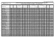
4 TECHNICAL DATACharacteristicsHeat outputHeat inputEfficiency 100%(N.C.V.)NG max flowrate G20NG max flowrate G30NG max flowrate G31Max flow rateof flueskW kcal/h kW kcal/h kW kcal/h % % m³/h kg/h kg/h kg/hMedium Temp.70°CTemp. flow/return50/30°CMedium Temp.70°CTemp. flow/return50/30°CCODEX 600 549 471.840 600 516.000 558 480.000 98,3 107,5 59,06 43,84 43,36 879,99CODEX 800 732 629.120 800 688.000 744 640.000 98,3 107,5 78,75 58,45 57,81 1173,38CODEX 1000 914 786.400 1000 860.000 930 800.000 98,3 107,5 98,44 73,06 72,27 1466,76CODEX 1200 1.097 943.680 1200 1.032.000 1116 960.000 98,3 107,5 118,12 87,67 86,72 1759,99CODEX 1400 1.280 1.100.960 1400 1.204.000 1302 1.120.000 98,3 107,5 137,81 102,28 101,17 2053,37CODEX 1600 1.463 1.258.240 1600 1.376.000 1488 1.280.000 98,3 107,5 157,50 116,89 115,63 2346,75CharacteristicsMinimumoutputMinimuminputEfficiency at 30%(N.C.V.)NG min flowrate G20NG min flowrate G30NG min flowrate G31Min flow rateof flueskW kcal/h kW kcal/h kW kcal/h % % m³/h kg/h kg/h kg/hMedium Temp.70°CTemp. flow/return50/30°CMedium Temp.70°CTemp. flow/return50/30°CCODEX 600 182 156.147 200 172.000 184 158.525 98,5 108,5 19,51 14,48 14,32 290,64CODEX 800 242 208.197 267 229.333 246 211.367 98,5 108,5 26,01 19,30 19,09 387,52CODEX 1000 303 260.220 333 286.638 307 264.182 98,5 108,5 32,51 24,13 23,86 484,35CODEX 1200 363 312.295 400 344.000 369 317.051 98,5 108,5 39,01 28,95 28,64 581,28CODEX 1400 424 364.344 467 401.333 430 369.892 98,5 108,5 45,51 33,78 33,41 678,16CODEX 1600 484 416.393 533 458.667 492 422.734 98,5 108,5 52,02 38,61 38,19 775,04CharacteristicsPressure lossesflue gas sideHeat losses throughthe chimneyHeat losses throughthe casingHeat losses withburner offFlue gas temp. at boileroutput and air at 20 deg. CCondenseproductionPress. losseswater sideDesignPressureTotalcapacityBoiler ElectricInsulationFrequencyweight supply classModello mbar % % % °C kg/h mbar bar l kg Volt ~ Hz IP WGASFor condensing For condensing For condensingTemp.For condensingTemp. flow/return Temp. flow/return Temp. flow/returnflow/return (ΔT=12K)Temp. flow/return50/30°C50/30°C50/30°C50/30°C50/30°CElectricpowerWith electr.contr. (excludedNat. gas Lpgpump andburner)CODEX 600 2,1 1,30 0,30 0,10 40 69,99 5 5 1191 1360 230 50 IP X0D 20 X XCODEX 800 3,7 1,30 0,30 0,10 40 93,32 5 5 1191 1360 230 50 IP X0D 20 X XCODEX 1000 4,2 1,30 0,30 0,10 40 116,65 5 5 1900 1776 230 50 IP X0D 20 X XCODEX 1200 6,2 1,30 0,30 0,10 40 139,97 5 5 1900 1776 230 50 IP X0D 20 X XCODEX 1400 8,3 1,30 0,30 0,10 40 163,30 5 5 1828 1850 230 50 IP X0D 20 X XCODEX 1600 10,8 1,30 0,30 0,10 40 186,64 5 5 1828 2103 230 50 IP X0D 20 X XFuel7
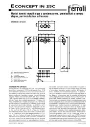
4.1 DIMENSIONS AND FITTINGSKEYN1 Boiler flowN2 Medium temperature returnN3 Accessory socket1. Level probe with integrated glow plug (not supplied as standard) - G1/2“2. Available connection - G1“1/23. Expansion vessel fitting - G1“1/24. Safety valve fitting - G1“1/45. Available connection - G1/2“6. Temperature control fitting - G1/2“7. Pressure switch fitting - G1/2“8. Termometers/termostats fitting - G1/2“9. Fuel shut-off valve fitting- G1/2“10. Air vent fitting - G3/4“11. Minimum level probe fitting - G1/2“N4 System filling/drainageN7 Boiler condensation drainN9 Low temperature returnDimensions H H2 H5 H6 H8 H9 H10 H12 L L1 L2 L4 P P2 P6 Øb Øc N1 N2 N4 N7 N9mm mm mm mm mm mm mm mm mm mm mm mm mm mm mm mm mm DN/in DN/in DN/in DN/in DN/inCODEX 600 1918 1462 1797 444 192 192 62 74 1363 1183 1168 959 1948 1212 250-300 280 350 100 80 3/4" 1" 100CODEX 800 1918 1462 1797 444 192 192 62 74 1363 1183 1168 959 1948 1212 250-300 280 350 100 80 3/4" 1" 100CODEX 1000 2020 1522 1880 453 202 202 62 85 1493 1313 1298 1060 2443 1732 250-300 320 350 125 100 3/4" 1" 125CODEX 1200 2020 1522 1880 453 202 202 62 85 1493 1313 1298 1060 2443 1732 250-300 320 350 125 100 3/4" 1" 125CODEX 1400 2165 1610 2022 440 205 205 62 81 3231 1395 1378 1165 2437 1725 250-300 320 400 125 100 3/4" 1" 125CODEX 1600 2165 1610 2022 440 205 205 62 81 3231 1395 1378 1165 2437 1725 250-300 320 400 125 100 3/4" 1" 1258
5 INSTALLATIONBefore connecting the boiler, the following operations must be completed:- Thoroughly clean all the system pipes in order to remove any foreign matter that could affect correct operationof the boiler;- Check that the flue has an adequate draught, that there is no narrowing of passages and that it is free fromdebris; also check that other appliances do not discharge into the flue (unless designed to serve several utilities).See the regulations in force.5.1 THERMAL PLANT5.1.1 BOILER ROOMAs a rule, regulations in force should be always observed. Premises in which boilers will be installed should be sufficientlyventilated and guarantee access for ordinary and extraordinary maintenance operations.5.2 BASEThe boiler should be installed on a stand, 100/200 mm high, in order to create an air trap in the condensate drain,which is designed to retain fumes and evacuate water.IMPORTANTMake sure the boiler supporting base is perfectly horizontal. The door must be at a uniform slope to providea proper drainage of the condensate to the smoke box.5.3 CHIMNEYThe pressurised boiler, is so-called, because it uses a burner provided with fan. The fan introduces into the combustionchamber, the exact amount of air necessary in relation to the fuel and maintains an overpressure in the furnaceequivalent to all the internal resistances of the flue gas path as far as the boiler exhaust. At this point the fanpressure should have dropped to zero to prevent the flue connection pipe and the lower area of the flue itself frombeing under pressure and combustion gas leaks occurring in the boiler room.The connection pipe from the boiler to the flue must slope incline in the direction of the flue gas flow with recommendedgradient of no less than 10%. Its path must be as short and straight as possible with the bends and fittingsrationally designed in accordance with air duct criteriaWARNINGThe flue gas temperature of this boiler is very low compare to the traditional non-condensing boilers,therefore, there is a very high humidity density. For this reason the boiler chimney must be water resistant,acid condense resistant and insulated to warrant sufficient draught.9
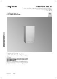
5.4 HYDRAULIC CONNECTIONS5.4.1 SEALED HOT WATER HEATING SYSTEM WITH EXPANSION VESSELKEY1 Hydraulic disconnect switch2 Filter a y3 Water flow switch4 Filling unit5 Tundish with articulated joint6 Pressure gauge7 Acid condense neutralizer8 Boiler switchboard9 Inspection well10 Safety pressure switch11 Pressure gauge cock12 Termometer probe13 Safety termostat probe14 Regulation termostat probe n°115 Regulation termostat probe n°216 Fuel shut-off valve probe17 Termometer18 Regulation thermostat n°119 Regulation thermostat n°220 Manual reset safety thermostat21 Shock absorbing pipe22 Safety valve (the 2 nd has a heating capacity above580 kW)23 Fuel shut-off valve24 Manual shut-off valve25 Manual shut-off valve for gas26 Expansion vessel27 Level probe glow plug (optional)28 System flow29 Probe sleeves inside the boiler30 Gas inlet31 Low temperature return32 Return water inlet from the plant33 Medium temperature return34 Boiler exhaust35 Acid condense outlet36 Neutralized condense outlet37 Outlet flue gas38 Air vent valve39 Burner10
Ensure that the hydraulic pressure measured after the reduction valve on the supply pipe does not exceed the operatingpressure specified on the rating plate of the component (boiler, heater etc.). As the water contained in the heating system increases in pressure during operation, ensure that its maximumvalue does not exceed the maximum hydraulic pressure specified on the component rating plate (5 bar). Ensure that the safety valve outlets of the boiler and hot water tank, if any, have been connected to drain in orderto prevent the valves from flooding the room if they open. Ensure that the pipes of the water and heating system are not used as an earth connection for the electricalsystem as this can seriously and very rapidly damage the pipes, boiler, heater and radiators. Once the heating system has been filled, you are advised to close the supply cock and keep it closed so thatany leaks from the system will be identified by a drop in hydraulic pressure indicated on the system pressuregauge.IMPORTANT!If the boiler is not supplied with acid condense neutralizer, a siphon must be fitted on thecondensate drain in order to avoid flue gas leakage.NOTE: IF ONLY ONE RETURN IS REQUIRED, ALWAYS USE THE LOW TEMPERATURE ONE11
5.5 INSULATION OF THE BOILER BODYThe boiler is supplied fixed to a wooden supporting base (1) to allow handling and to facilitate the insulation process.The glass wool insulation, consisting of 3 layers, must be wrapped on the parts shown in the figure and fixed to theconnection sides by the appropriate clamps supplied.11Once the glass wool is attached, the wooden support can be removed and the boiler can be placed in its final position.12
5.6 HOW TO ASSEMBLE THE CASE AND THE CONTROL PANEL1) Prepare the staves by inserting the four stoppers, as shown in the figure.2) Secure the front struts to the plate using the appropriate screws and nuts.3) Fix the two items (1 and 2), which form the “stave steering” strut, to the front/back plate. Fit the internal item(1), right and left, paying attention to the hole that is closer to the edge and also on the lower side.2113
4) Fix the special “stave steering” struts to the upper/lower plate proceeding as described above.5) Then, in the same way, fix the two (front and back) beams.NB: only models 1400/1600 kW require previous installation of the “spacer” staves, by applying the reverse technique:the larger part to the front side and the straight part to the back.14
6) Insert the 4 short staves (previously prepared with the stoppers) between the struts, on each side.7) Insert the staves, including the one designed for the installation of the control panel.HOW TO ASSEMBLE THE CONTROL PANELThe control panel supplied in the boiler kit can be installed either to the right-hand side or the left-hand side of thewall.The panel must be fixed to the corresponding stave (1) which has pre-prepared holes for the screws and slots forthe capillary inlets.43218) Fix the control panel (2) to the supporting stave and pass the capillaries (3) through the stave slot until theyreach the bulb basins in the equipped socket (4), fitted on the boiler delivery line (inside the furnace).15
9) After you have finished installing all the staves, proceed with the assembly of the closing frame, using the 4self-threading screws.10) View of the boiler with the case and control panel in position.16
5.7 ELECTRICAL CONNECTIONSElectrical systems of thermal plants designed only for heating purposes must comply with numerous legal regulationswhich apply to in general as well as specifically to each application or fuel type.5.8 OPTIONAL CONTROL PANELThe control panel (optional) with the boilers is made of self-extinguishing plastic and houses the regulation andsafety instruments:LEGEND1 PANEL LIVE2 BURNER SWITCH N. 14 HEATING PUMP SWITCH7 BOILER THERMOMETER8 BOILER LIMIT THERMOSTAT9 SAFETY THERMOSTAT N° 111 2nd FLAME THERMOSTATThe upper part of the control panel can be rotated to gain access to the terminal board and uncoil the thermostatand thermometer capillaries. A copy of the wiring diagram is contained inside the control panel cover.The control thermostats (TR1-TR2) have an operating range from 0° to 90° and can be set by the user by meansof the front dial.Safety limit thermostats (TS) has a fixed setting of 100 (+0/-6)°C and can be manually reset.For correct installation, refer to the boiler casing assembly instructions.Wiring diagramRefer to the diagram supplied with the specific switchboard.17
5.9 STARTINGOpen the gas tap (check if there is any gas leakage).Switch on the burner and heating pump on the control panel.At this point if the water temperature inside the boiler is less that the value set up on the control thermostat and theroom thermostat/timer (if present) is closed, the burner and the pump will run.WARNINGIt is common to find air inside the gas pipe-work, especially during the initial start up or after a long period of withoutuse. So if the flame failure occurs, repeat the same operation as previously explained.NOTE: control pumps are running.CONNECTION LIVE/NEUTRALIf the connections of the live and the neutral are not correct, the burner will stop at the end of the safetytime (even if the burner is running).18
5.10 REVERSING THE DOOR HINGE POSITIONIf the door is to be opened to the opposite side, act as follows:1. Switch the outside nut (or bush) of one hinge with the diametrically opposite closure bush; then at the hingeside, fasten the cone to the door with the inside nut.2. Repeat the operation for the other hinge.3. For any adjustment needed, act on the specific hinge nuts.5.11 BURNER CONNECTIONBefore installation you are advised to thoroughly clean the inside of all the fuel supply system pipes in order to removeany foreign matter that could affect correct operation of the boiler. See technical specification tables and check themax pressure value inside the furnace.a) Check the internal and external seal of the gas supply system;b) Regulate the gas flow according to the power required by the boiler;c) Check that the boiler is fired by the correct type of gas;d) Check that the supply pressure is within the values specified on the burner rating plate;e) Check that the supply system is sized for the maximum flow rate necessary for the boiler and that it is providedwith all control and safety devices provided for by the regulations referred to above;f) Check that the boiler room vents are sized in order to guarantee the air flow established by the regulations referredto above and that they are in any case sufficient to obtain perfect combustion.In particular,g) Check that the feeding line and the gas ramp comply with the regulations in force;h) Check that all the gas connections are sealed;i) Check that the gas pipes are not used as earth connections for electrical appliances.If the boiler is not going to be used for some time, close the fuel supply cock or cocks.IMPORTANT: check that the air spaces between the burner draught tube and the boiler door are suitablyfilled with thermo-insulating material (see fig.). The boiler is supplied with a piece of ceramic rope. Should thisnot suit the burner used, use a braid of different diameter but same material.P6132ØbKEY:1. Burner2. Manhole3. Thermoinsulating material4. Flange4All details on the draught tube lenght (P6), the diameter of the burner hole (Øb) and the pressurization are includedin the par. Technical Specifications.ATTENTION: The boiler is designed for use with NATURAL GAS and LPG.The use of other fuels will void the boiler warranty.19
6 START UP6.1 PRELIMINARY CHECKSBefore starting the boiler, check that:- The rating plate specifications and power supply network (electricity, water, gas) specifications correspond;- The burner power range is compatible with the power of the boiler;- The boiler room also contains the instructions for the burner;- The flue gas exhaust pipe is operating correctly;- The air inlet supply is well dimensioned and free from any obstacle;- The boiler door, the smoke box and the burner plate are closed in order to provide a complete flue gas seal;- The system is full of water and that any air pockets have therefore been eliminated;- The anti-freeze protections are operative;- The water circulation pumps are operating correctly.- The expansion vessel and the safety valve(s) have been connected correctly (with no interception) and areproperly operating.- Check the electrical parts and thermostat operation.6.2 WATER TREATMENTIf the boiler is to be installed in an existing system where there could be frequent losses from the systemor if the hardness of the water is greater than 10 F, it will be necessary to use a filter and a softener for systemwater and control the pH above 8-9.The most common phenomena that occur in heating systems are:- ScalingScale obstructs heat transfer between the combustion gases and the water, causing an abnormal increase inthe temperature of the metal and therefore reducing the life of the boiler.Scale is found mostly at the points where the wall temperature is highest and the best remedy, at constructionlevel, is to eliminate areas that overheat.Scale creates an insulating layer, which reduces the thermal transfer of the boiler, affecting system efficiency. Thismeans that the heat produced by burning the fuel is not fully transferred and is lost to the flue.Scale diagramKey% % fuel not usedmm mm scale- Corrosion on the water sideCorrosion of the metal surfaces of theboiler on the water-side is due to thepassage of dissolved iron through itsions (Fe+). In this process the presenceof dissolved gases and in particular ofoxygen and carbon dioxide is very important.Corrosion often occurs with softenedor de-mineralised water, which has a more aggressive effect on iron (acid water with Ph
7 OPERATION7.1 OPERATION CHECKSThe heating system must be used suitably, ensuring on the one hand, optimum combustion with reduced emissionto the atmosphere of carbon monoxide, hydrocarbons and soot, and on the other avoiding all damage to personsand property.The pressurisation must remain within the limit values shown in the technical data table.The burner switch should always remain on; this ensures that the boiler water temperature remains near the valueset by the thermostat.In the case of flue gas leaks from the front of the boiler (door and burner plate), the closure tie rods of thesingle parts must be adjusted; if this is not sufficient, replace the gaskets.WARNINGDo not open the door and do not remove the fume chamber while the burner is in operation. In all caseswait a few minutes after stopping the burner for the insulation to cool.7.2 TEMPORARY BOILER STOPTo stop the boiler temporarily, set the main switch on the control panel to “OFF”. The electrical parts will now befree of power.7.3 PROLONGED BOILER STOPClose the gas valve that is fitted upstream of the boiler.WARNING: During long stoppages in winter, and in order to avoid frost damage, drain the heating system water.7.4 PERIODICAL USER CHECKS- Check periodically that there is no air in the heating system, and if necessary open the vent valve at the top ofthe boiler.- Periodically check the boiler pressure.7.5 MAINTENANCE AND CLEANINGAll maintenance and cleaning can only be carried out only after closing the fuel supply and switching off the electricalsupply.As economic operation depends on the cleanliness of the heat exchanger surfaces and on burner adjustment, it isrecommended to:- Have the burner settings checked by professionally qualified personnel;- Analyse the system water and allow for adequate water treatment to avoid the formation of calcareous incrustationsthat initially reduce boiler efficiency, and then lead to damage;IMPORTANTRegular maintenance of the boiler is recommended, by looking through the special side inspectioncaps (see the Technical Data section) for any lime deposits and carrying out a chemical cleaning, if required.- Check that the ceramic insulation around the doors, the gaskets for smoke (glass braid insulation on the doors)and the rubber lip seal (smoke box) are intact; fix them if necessary;- Check that the flame driving box inside the furnace is intact.- Open the lower door and check that the drain pipe, which collects the condensate from the front tube plate andconveys it directly to the smoke box, is not clogged and clean it if required.- Periodically check the efficiency of the regulation and safety instruments on the system.NOTE:Before you disassemble the smoke box we recommend removing the surrounding glass wool layer, which ishooked to the insulation material by a fastening spring.21
ICI CALDAIE SpAVia G. Pascoli, 3837059 Campagnola di Zevio VRTelefono 045 8738511Fax 045 8731148Info@icicaldaie.comwww.icicaldaie.comPartita Iva 00227490232Rag. Soc. n. 6677C.C.I.A.A. VR n. 69600Appartenente al Gruppo FinlucIscritto R.I. VR 02245640236DECLARATION OF CONFORMITY WITHTHE EUROPEAN COMMUNITY REGULATIONSI undersigned Emanuela Lucchini, Managing Director of ICI CALDAIE S.p.A., headquartedin via G. Pascoli 38 – 37059 Campagnola di Zevio (VR) ItalyDECLARE THAT STEEL BOILERSCODEXcomply with the CE certificate and with the following regulations (or harmonisedregulations):EN 60335-1, EN 303-1, pr EN 303-3In accordance with the boards regulations:- Gas Directive 90/396/CEE- Low Voltage Directive 73/23/CEE (modified by 93/68)- Efficiency Directive 92/42/CEE- EMC Directive 89/336/CEECampagnola di Zevio, li 14/05/2010*The Declaration of Conformity of the burner is enclosed in the relative documentation.
Appartenente al Gruppo Finluc, iscritto R.I. VR n. 02245640236Via G. Pascoli, 38 - 37059 Zevio - fraz. Campagnola - VERONA - ITALIATel. 045/8738511 - Fax 045/8731148info@icicaldaie.com - www.icicaldaie.comThe data listed is indicative only and is not binding. Our company reserves the right to introduce alterations at any time as it deems fit andproper for the development of the product.93120285 Ed. 3-05/11 3 - St. 10- 05/11