
You also want an ePaper? Increase the reach of your titles
YUMPU automatically turns print PDFs into web optimized ePapers that Google loves.
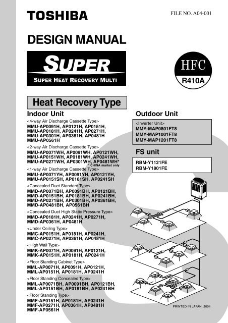
FILE NO. A04-001DESIGN MANUALR410AHeat Recovery Type<strong>Indoor</strong> <strong>Unit</strong>MMU-AP0091H, AP0121H, AP0151H,MMU-AP0181H, AP0241H, AP0271H,MMU-AP0301H, AP0361H, AP0481HMMU-AP0561HMMU-AP0071WH, AP0091WH, AP0121WH,MMU-AP0151WH, AP0181WH, AP0241WH,MMU-AP0271WH, AP0301WH, AP0481WH** CHINA market onlyMMU-AP0071YH, AP0091YH, AP0121YH,MMU-AP0151SH, AP0181SH, AP0241SHMMD-AP0071BH, AP0091BH, AP0121BH,MMD-AP0151BH, AP0181BH, AP0241BH,MMD-AP0271BH, AP0301BH, AP0361BH,MMD-AP0481BH, AP0561BHMMD-AP0181H, AP0241H, AP0271H,MMD-AP0361H, AP0481HMMC-AP0151H, AP0181H, AP0241H,MMC-AP0271H, AP0361H, AP0481HMMK-AP0071H, AP0091H, AP0121H,MMK-AP0151H, AP0181H, AP0241HMML-AP0071H, AP0091H, AP0121H,MML-AP0151H, AP0181H, AP0241HMML-AP0071BH, AP0091BH, AP0121BH,MML-AP0151BH, AP0181BH, AP0241BHMMF-AP0151H, AP0181H, AP0241HMMF-AP0271H, AP0361H, AP0481HMMF-AP0561HOutdoor <strong>Unit</strong>MMY-MAP0801FT8MMY-MAP1001FT8MMY-MAP1201FT8FS unitRBM-Y1121FERBM-Y1801FEPRINTED IN JAPAN, 2004
CONTENTSDESIGN MANUAL ..................................................................31. OUTLINE OF TOSHIBA SUPER MMS(SUPER HEAT RECOVERY MULTI SYSTEM) ................................... 32. SUMMARY OF SYSTEM EQUIPMENTS ............................................ 63. BASIC SYSTEM CONFIGURATION ................................................. 114. EQUIPMENT SELECTION PROCEDURE........................................ 145. REFRIGERANT PIPING DESIGN ..................................................... 236. WIRING DESIGN ................................................................................ 287. CONTROLS ........................................................................................ 328. ACCESSORIES .................................................................................. 389. TECHNICAL SPECIFICATIONS........................................................ 4010. FAN CHARACTERISTICS ................................................................. 5111. DIMENSIONAL DRAWINGS.............................................................. 54
DESIGN MANUAL1. OUTLINE OF TOSHIBA SUPER HRM(Super Heat Recovery Multi System)Shortest route design by free branchingCombination of line and header branching is highly flexible.This follows for the shortest design route possible, thereby savingon installation time and cost. Line/header branching afterheader branching is only available with TOSHIBA Super HRM.Line branchingOutdoor unit<strong>Indoor</strong> unitBranching jointFS unit8FHeader branchingOutdoor unitBranchingheader7F<strong>Indoor</strong> unitFS unitLine + Header branchingOutdoor unitHeaderFSunit2FBranching joint<strong>Indoor</strong>unitLine branching after header branchingOutdoor unit1FSuper MMS Only HRMOnlyHeaderBranching jointFS unit<strong>Indoor</strong> unitHeader branching after header branchingOutdoor unitSuper HRMOnlyHeader<strong>Indoor</strong> unitHeaderFS unit3
• Non-polarized control wiringbetween outdoor and indoor unitsOutdoor unitU1 U2<strong>Indoor</strong> unitU1 U2 U1 U2 U1 U28F7Fmain heat exchangerSub heat exchangerOutdoor unitFS unit<strong>Indoor</strong>unitHeating Cooling Cooling Cooling• Simultaneous operationCompressor2FOutdoorunitAllowable pipe length :125m equivalent lengthHeight difference between indoorunit and outdoor unit : 50mHeight difference between indoorunit and indoor unit : 35m1st branchingsection1FFrom 1st branching to thefarthest indoor unit : 50m4
Energy savingNo. 1 COP in heat recovery VRF industry. Compared with the conventional chiller fan coil system,a large energy saving can be realized.Advanced bus communication systemWiring between indoor and outdoor unit is a simple 2 wire system.Communication address is also automatically configured.A default test mode operation is available.Self diagnostics systemComprehensive troubleshooting code allows for timely identification of problems arising.High lift designEquivalent pipe length of 125m and vertical lift of 50m is made possible with TOSHIBA Super HRM.Vertical lift between indoor units of 35m is the highest in the industry.This allows for greater flexibility in the location of the system.Simultaneous operationBy controling the FS unit, Super HRM enables freely simultaneous operation of cooling and heading.This operation meets the various needs of modern buildings that has highly airtight or an increasingheat load due to use of computers. Also, Super HRM improves energy efficiency by recyclingexhaust heat.Compact FS unit designThe compact and light weight design of the FS unit (Flow selector unit) allows it to be easilyinstalled in limited spaces.Intelligent controlTOSHIBA Super HRM intelligent controls and modulating valves deliver the required capacity,according to the load variation from 50% to 100%.The intelligent controls and modulating valves limit or increase the cooling capacity dynamically sohumidity and temperature are kept in the comfort zone.Conforms to building control lawIAQ (<strong>Indoor</strong> Air Quality) is also achieved by combining various accessories required by the BuildingControl Law.Wide control applicationsArtificial Intelligence Network system• Central control and monitoring system available• Weekly schedule operation through weekly timerIntegration with Building Management System (BMS) is available.5
2. SUMMARY OF SYSTEM EQUIPMENTSEquipments1. Outdoor unitsCorresponding HPInverter unit8HP 10HP 12HPAppearanceModel name MMY- MAP0801FT8 MAP1001FT8 MAP1201FT8Cooling capacity (kW) 22.4 28.0 33.5Heating capacity (kW) 25.0 31.5 35.52. FS units (Flow selector units)Model nameRBM-Y1121FEUsageCapacity rank for indoor unit : Type 007 to 030AppearanceRBM-Y1801FECapacity rank for indoor unit : Type 036 to 056*Accessory part (Sold separately): Connection cable kit (RBC-CBK15FE), up to 15m.3. Branching joints and headersModel nameUsageAppearance<strong>Indoor</strong> unit capacity code (*1)RBM-BY53FEY-shape branching Total below 6.4 For 3joint (*3) <strong>Indoor</strong> unit capacity code (*1) pipingRBM-BY103FETotal below 14.2RBM-BY53ERBM-BY103E<strong>Indoor</strong> unit capacity code (*1)Total below 6.4 For 2<strong>Indoor</strong> unit capacity code (*1)pipingTotal below 14.2 (*5)<strong>Indoor</strong> unit capacity code (*1) For 3RBM-HY1043FE4-branching Total below 14.2 pipingheader (*4) <strong>Indoor</strong> unit capacity code (*1) For 2RBM-HY1043ETotal below 14.2 piping (*5)<strong>Indoor</strong> unit capacity code (*1) For 3RBM-HY1083FE8-branching Total below 14.2 pipingheader (*4) <strong>Indoor</strong> unit capacity code (*1) For 2RBM-HY1083ETotal below 14.2 piping (*5)*1 “Capacity code” can be obtained from page 8. (Capacity code is not actual capacity)2 If total capacity code value of indoor unit exceeds that of outdoor unit, apply capacity code of outdoor unit.3 When using Y-shape branching joint for 1st branching, select according to capacity code of outdoor unit.4 Max. 6.0 capacity code in total can be connected.5 This is used for branching to “cooling only” indoor unit.6 Model names for outdoor and indoor units described in this guide are shortened because of the space constraint.6
50HzSuper Heat Recovery Multi System Outdoor <strong>Unit</strong>HP (Capacitycode)Model nameMMY-No. ofcombinedunitsInverter8 HPMMY-8HP ( 8) MAP0801HT8 1 MAP0801FT8 1UsedQ'tyInverter10 HPMMY-10HP (10) MAP1001HT8 1 MAP1001FT8 1UsedQ'tyInverter12 HPMMY-12HP (12) MAP1201HT8 1 MAP1201FT8 1UsedQ'ty1. Allocation standard of model nameMMY– M AP F T 8Power supply specifications, 3Ø 380–415 V, 50Hz ....... 8T : Capacity variable unitF : Heat recoveryDevelopment series No.Capacity rank HP x 10New refrigerant R410AM : Single module unit, No mark : Combined Model nameModular Multi2. Rated conditions (Rated mode : Condition)Cooling : <strong>Indoor</strong> air temperature 27°C DB/19°C WB, Outdoor air temperature 35°C DBHeating : <strong>Indoor</strong> air temperature 20°C DB, Outdoor air temperature 7°C DB/6°C WB7
4. <strong>Indoor</strong> unitCoolingcapacity (kW)Heatingcapacity (kW)MMU-AP0091H 009 type 1 2.8 3.2MMU-AP0121H 012 type 1.25 3.6 4.0MMU-AP0151H 015 type 1.7 4.5 5.0MMU-AP0181H 018 type 2 5.6 6.3MMU-AP0241H 024 type 2.5 7.1 8.0MMU-AP0271H 027 type 3 8.0 9.0MMU-AP0301H 030 type 3.2 9.0 10.0MMU-AP0361H 036 type 4 11.2 12.5MMU-AP0481H 048 type 5 14.0 16.0MMU-AP0561H 056 type 6 16.0 18.0MMU-AP0071WH 007 type 0.8 2.2 2.5MMU-AP0091WH 009 type 1 2.8 3.2MMU-AP0121WH 012 type 1.25 3.6 4.0MMU-AP0151WH 015 type 1.7 4.5 5.0MMU-AP0181WH 018 type 2 5.6 6.3MMU-AP0241WH 024 type 2.5 7.1 8.0MMU-AP0271WH 027 type 3 8.0 9.0MMU-AP0301WH 030 type 3.2 9.0 10.0MMU-AP0481WH* 1) 048 type 5 14.0 16.0MMU-AP0071YH 007 type 0.8 2.2 2.5MMU-AP0091YH 009 type 1 2.8 3.2MMU-AP0121YH 012 type 1.25 3.6 4.0MMU-AP0151SH 015 type 1.7 4.5 5.0MMU-AP0181SH 018 type 2 5.6 6.3MMU-AP0241SH 024 type 2.5 7.1 8.0MMD-AP0071BH 007 type 0.8 2.2 2.5MMD-AP0091BH 009 type 1 2.8 3.2MMD-AP0121BH 012 type 1.25 3.6 4.0MMD-AP0151BH 015 type 1.7 4.5 5.0MMD-AP0181BH 018 type 2 5.6 6.3MMD-AP0241BH 024 type 2.5 7.1 8.0MMD-AP0271BH 027 type 3 8.0 9.0MMD-AP0301BH 030 type 3.2 9.0 10.0MMD-AP0361BH 036 type 4 11.2 12.5MMD-AP0481BH 048 type 5 14.0 16.0MMD-AP0561BH 056 type 6 16.0 18.0MMD-AP0181H 018 type 2 5.6 6.3MMD-AP0241H 024 type 2.5 7.1 8.0MMD-AP0271H 027 type 3 8.0 9.0MMD-AP0361H 036 type 4 11.2 12.5MMD-AP0481H 048 type 5 14.0 16.0MMC-AP0151H 015 type 1.7 4.5 5.0MMC-AP0181H 018 type 2 5.6 6.3MMC-AP0241H 024 type 2.5 7.1 8.0MMC-AP0271H 027 type 3 8.0 9.0MMC-AP0361H 036 type 4 11.2 12.5MMC-AP0481H 048 type 5 14.0 16.0MMK-AP0071H 007 type 0.8 2.2 2.5MMK-AP0091H 009 type 1 2.8 3.2MMK-AP0121H 012 type 1.25 3.6 4.0MMK-AP0151H 015 type 1.7 4.5 5.0MMK-AP0181H 018 type 2 5.6 6.3MMK-AP0241H 024 type 2.5 7.1 8.0MML-AP0071H 007 type 0.8 2.2 2.5MML-AP0091H 009 type 1 2.8 3.2MML-AP0121H 012 type 1.25 3.6 4.0MML-AP0151H 015 type 1.7 4.5 5.0MML-AP0181H 018 type 2 5.6 6.3MML-AP0241H 024 type 2.5 7.1 8.0MML-AP0071BH 007 type 0.8 2.2 2.5MML-AP0091BH 009 type 1 2.8 3.2MML-AP0121BH 012 type 1.25 3.6 4.0MML-AP0151BH 015 type 1.7 4.5 5.0MML-AP0181BH 018 type 2 5.6 6.3MML-AP0241BH 024 type 2.5 7.1 8.0MMF-AP0151H 015 type 1.7 4.5 5.0MMF-AP0181H 018 type 2 5.6 6.3MMF-AP0241H 024 type 2.5 7.1 8.0MMF-AP0271H 027 type 3 8.0 9.0MMF-AP0361H 036 type 4 11.2 12.5MMF-AP0481H 048 type 5 14.0 16.0MMF-AP0561H 056 type 6 16.0 18.0*1) China onlyType Appearance Model name Capacity rank Capacity code4-way Air DischargeCassette Type2-way Air DischargeCassette Type1-way Air DischargeCassette TypeConcealed DuctStandard TypeConcealed DuctHigh StaticPressure TypeUnder Ceiling TypeHigh Wall TypeFloor StandingCabinet TypeFloor StandingConcealed TypeFloor Standing Type8
5. Remote controllerName ModelnameAppearanceApplicationFunctionWired remote controllerRBC-AMT21ESET DATAUNIT No.SETTINGTESTR.C. No.UNITSET CLCODE No.Connected to indoor unitWired remotecontrollerWired remote controller(In case of control by2 remote controllers)• Start / Stop• Changing mode• Temperature setting• Air flow changing• Timer function Either “ON” time or “OFF” time or “CYCLIC”can be set how many 30 min. later ON orOFF is operated. Combined with the weekly timer, weeklyschedule operation can be operated.• Filter signDisplays automatically maintenance time ofindoor filter.Filter sign flashes.• Self-diagnosis functionPressing “CHECK” button displays cause oftrouble on the check code.• Control by 2 remote controllers is available.Two remote controllers can be connected to oneindoor unit. The indoor unit can be separatelyoperated from the isolated places.Simple remote controllerRBC-AS21ETESTSETTING˚C˚FConnected to indoor unitSimple remote controller• Start / Stop• Temperature setting• Air flow changing• Check code displayWireless remote controller kitTCB-AX21E RBC-AX22CE TCB-AX21U (W)-EConnected to indoor unit• Start / Stop• Changing mode• Temperature setting• Air flow changing• Timer functionEither “ON” time or “OFF” time or “CYCLIC”can be set how many 30 min. later ON or OFFis operated.• Control by 2 remote controllers is available.Two wireless remote controllers can operateone indoor unit. The indoor unit can beseparately operated from the isolated places.• Check code displayTCB-AX21U (W)-E(For 4-way air discharge cassette)RBC-AX22CE(For under ceiling)TCB-AX21E(For others except concealed duct high staticpressure)9
Name ModelnameAppearanceApplicationPerformanceConnected to centralremote controller,wired remote controller• Weekly schedule operation Setting different start / stop time foreach day of the week ON / OFF can be easily set 3 timesa day.ONOFF ON OFF ON OFF8:00 12:00 13:00 18:00 19:00 21:00Weekly timerRBC-EXW21EPROGRAM1PROGRAM2PROGRAM3WEEKLY TIMERSuMoTuWeTh Fr SaERRORWiredremote controllerOutdoor unitWeeklytimer “CHECK” “PROGRAM” “DAY”button make setting copy easy. Two patterns of schedule for aweek can be specified.(Summer schedule and winterschedule, etc.) “CANCEL” “DAY” button makeholiday setting easy. If power supply fails, the settingcontents are stored in memory, for100 hours.Centralremote controllerWeeklytimerConnected to outdoor unit,indoor unitOutdoorunit• Individual control up to 64 indoor units.• Individual control for max. 64 indoorunits divided 1 to 4 zone.⎛ Up to 16 indoor units for each ⎞⎝ zone⎠• Up to 16 outdoor header units areconnectable.Central remote controllerTCB-SC642TLEALL ZONEZONEGROUP1234UNIT No. TESTSET DATASETTING R.C. No.SELECT ZONECL SETGROUPCODENo.Centralremote controller• 4 type central control setting to inhibitindividual operation by remotecontroller can be selected.• Setting for one of 1 to 4 zone isavailable.• Usable with other central controldevices (Up to 10 central controldevices in one control circuit)• Two control mode selectivity⎛ Central controller mode⎝ Remote controller mode⎞⎠• Setting of simultaneous ON/OFF 3times for each day of the weekcombined with weekly timer.Centralremotecontroller<strong>Indoor</strong>remote controller10
3. BASIC SYSTEM CONFIGURATIONSystem legend (ex.)• Max. indoor unit : 13 units• Capacity code of indoor unit : ⎛ Min. : 5.6⎜⎝Max. : 10.8Capacity codeTotal 10.4No. of total units13Outdoor unit8HP10.4 4.8 4.0 3.2 2.4 1.6007(0.8)007(0.8)Capacity codeover the branch(0.8 + 0.8 = 1.6)007(0.8)007(0.8)007(0.8)<strong>Indoor</strong> unitdesignation007(0.8)Capacitycode5.6 4.8 4.0 3.2 2.4 1.6 0.8FS unit<strong>Indoor</strong> unit 007 007 007 007 007 007 007(0.8) (0.8) (0.8) (0.8) (0.8) (0.8) (0.8)Remotecontroller11
10 HP system• Max. indoor unit : 16 units• Capacity code of indoor unit : ⎛ Min. : 7⎜⎝ Max. : 13.5Capacity codeTotal 12.8No. of total units16Outdoor unit10HP12.8 6.4 5.6 4.8 4.0 3.2 2.4 1.6007(0.8)007(0.8)007(0.8)007(0.8)007(0.8)007(0.8)007(0.8)007(0.8)6.4 5.6 4.8 4.0 3.2 2.4 1.6FS unit<strong>Indoor</strong> unit 007 007 007 007 007 007 007(0.8) (0.8) (0.8) (0.8) (0.8) (0.8) (0.8)Remotecontroller007(0.8)12
12 HP system• Max. indoor unit : 16 units• Capacity code of indoor unit : ⎛ Min. : 8.4⎜⎝ Max. : 14.4Capacity codeTotal 14.0No. of total units16Outdoor unit12HP14.0 6.4 5.6 4.8 4.0 3.2 2.4 1.6007(0.8)007(0.8)007(0.8)007(0.8)007(0.8)007(0.8)007(0.8)007(0.8)7.6 6.8 6.0 5.0 4.0 3.0 2.0FS unit<strong>Indoor</strong> unit 007 007 009 009 009 009 009Remotecontroller(0.8)(0.8)(1.0)(1.0)(1.0)(1.0)(1.0)009(1.0)13
4. EQUIPMENT SELECTION PROCEDURE1. Selection flow chart1. Determination of indoor air conditioning load2. Preliminary selection of indoor units3. Preliminary selection of outdoor unit with indoor units4. Capacity correction for piping length/height between indoor and outdoor units5. Capacity correction based on indoor and outdoor temperature6. Validate preliminary selection of indoor unitsNO7. Confirmation of selection for indoor unit and outdoor unitsEnd2. Combination conditions for indoor unit and outdoor unit1. For indoor unit, the capacity code is decided for each capacity rank.Capacity rank type 007 009 012 015 018 024 027 030 036Capacity code 0.8 1 1.25 1.7 2 2.5 3 3.2 4NOTE :Capacity rank : Correspondence to Btu/h. Capacity code : Correspondence to Horsepower.048505662. For outdoor unit, maximum No. of connectable indoor units and total capacity code of indoor units are decided.Outdoor unit(Heat recovery)Capacity code ofoutdoor unitMax. No. ofindoor unitsTotal capacity codeof indoor unitsMMY-MAP0801FT8 8 13 5.6 to 10.8MMY-MAP1001FT8 10 16 7.0 to 13.5MMY-MAP1201FT8 12 16 8.4 to 14.470 to 135% of outdoor unit capacity for 8, 10HP70 to 120% of outdoor unit capacity for 12HP14
3. Cooling/heating capacity characteristics1. Cooling capacity calculation method :Required cooling capacity = Cooling capacity x Factor (, , , , * 1 ) kW <strong>Indoor</strong> air wet bulb temperature vs. capacity correction valueCapacity correction value1.21.11.00.90.81520 24<strong>Indoor</strong> air wet bulb temp. (˚C) Outdoor air dry bulb temperature vs.capacity correction valueCapacity correction value1.21.11.00.9–5 0 5 10 15 20 25 30 35 40 43Outdoor air dry bulb temp. (˚C) Air flow variation ratio of indoor unit vs. capacity correction (For concealed duct type only)Capacity correction value1.11.00.980 90 100 110 120Air flow variation ratio (%)*1 : Coefficient to use for correction of outdoor unit capacity when total capacity of the indoorunits are not equal to the outdoor unit capacity.15
Connecting pipe length and lift difference between indoor and outdoor units vs. capacity correction valueHeight of outdoor unit H (m)50403020100–10–20–30–400Outdoor unit (8 to 12HP)98 %100969492908886848280781020 30 40 50 60 70 80 90 100 110 120Pipe length (Equivalent length) L (m)hol’oOutdoor unitL’ is the longest one of(l’o + l’a, l’o + l’b, l’o + l’c)H = ho +(Largest one of ha, hb, and hc)hchbhal’al’bl’cAB <strong>Indoor</strong> unitC Correction of outdoor unit diversity120Correction (%)100806040200 20 40 60 80 100 120 135Standard capacity ratio<strong>Indoor</strong> units total capacity ratio (%)*1 : Coefficient to use for correction of outdoor unit capacity when total capacity of the indoorunits are not equal to the outdoor unit capacity.16
2. Heating capacity calculation method :Required heating capacity = Heating capacity x Factor (, , , , * 1 , * 2 ) kW <strong>Indoor</strong> air dry bulb temperature vs. capacity correction valueCapacity correction value1.21.11.00.90.815 20 24<strong>Indoor</strong> air dry bulb temp. (˚C) Outdoor air wet bulb temperature vs. capacity correction valueCapacity correction value1.21.11.00.90.80.70.60.5–15 –10 –5 0 5 10 15Outdoor air wet bulb temp. (˚C) Air flow variation ratio of indoor unit vs. capacity correction (For concealed duct type only)Capacity correction value1.11.00.980 90 100 110 120Air flow variation ratio (%)*1 : Coefficient to use for correction of outdoor unit capacity when total capacity of the indoorunits are not equal to the outdoor unit capacity.*2 : Refer to item 3 in page 18.17
Connecting pipe length and lift difference between indoor and outdoor units vs. capacity correction valueHeight of outdoor unit H (m)50403020100–10Outdoor unit (8 to 12HP)100%9998979695949392–20–30–400 10 20 30 40 50 60 70 80 90 100 110 120Pipe length (Equivalent length) L (m)hohchbl’ohaOutdoor unitL’ is the longest one of(l’o + l’a, l’o + l’b, l’o + l’c)H = ho +(Largest one of ha, hb, and hc)l’al’bl’cABC<strong>Indoor</strong> unit Correction of outdoor unit diversity120Correction (%)10080604020020 40 60 80 100 120 135Standard capacity ratio<strong>Indoor</strong> units total capacity ratio (%)*1 : Coefficient to use for correction of outdoor unit capacity when total capacity of the indoorunits are not equal to the outdoor unit capacity.3. Capacity correction in case of frost on the outdoor heat exchanger in heatingCorrect the heating capacity when frost was found on the outdoor heat exchanger.Heating capacity = Capacity after correction of outdoor unit × Correction value of capacity resulted from frost(Capacity after correction of outdoor unit : Heating capacity calculated in the above item 2.)6 Capacity correction in case of frost on the outdoor heat exchangerCapacity correction value1.00.90.8–15 –10 –5 0 5 10Outdoor air wet bulb temp. (˚C)18
4. Capacity calculation for each indoor unitCapacity for each indoor unitRequired standard capacity of indoor unit= Capacity after correction of outdoor unit ×Total value of standard indoor unit capacity5. Operating temperature rangeIn cooling timeIn heating time4520Outdoor air dry bulb temp. (˚C)4035302520151050–5ContinuouslyoperablerangeUsable range(in pull down)Outdoor air wet bulb temp. (˚C)151050–5–10–15Usable range(in warming-up)Continuouslyoperablerange–1010152025 2830–205 10 15 20 25 30<strong>Indoor</strong> air wet bulb temp. (˚C)<strong>Indoor</strong> air dry bulb temp. (˚C)* The unit can be operated even if outdoor temperature gets down to -20°C, however note that the warrantycovers only up to -15°C because operation beyond that temperature is out of specification.* When outdoor air temperature falls to under -15°C, it may cause shortening the product lifetime.* When outdoor temperature goes out of specified range “display and required operation will stop.or ” mark is indicated on the remote controller“ & ”: When heating operation“ ”: When cooling operation[Notice]• This indication is not failure.• When outdoor temperature goes back to specified range, “ or ” disappear and start normal operation.• Operation stops because concurrent operation can not be kept in the condition of out of specification forSuper HRM.(Outdoor temp.(DB) 21°C: Heating)* Do not use “Super HRM” for other than personal usage where the ambient temperature may go down below-5°C. (For example, OA equipment/Electric device/Food/Animals and plants/Art object)6. Rated conditionsCooling :<strong>Indoor</strong> air temperature 27°C DB/19.0°C WB, Outdoor air temperature 35°C DBHeating :<strong>Indoor</strong> air temperature 20°C DB, Outdoor air temperature 7°C DB/6°C WB19
4. Example of equipment selectionThe following shows an example of equipment selection based upon a building modelFig. 1 Overview of building model8m2F2 – 1 2 – 2 2 – 32 – 4 2 – 5Office rooms(2–1, 2–2 : Computer room)2F1F14.4m7.2m1F1 – 11 – 21 – 41 – 3Stores(1-4 : Kitchen)Non-air conditioning zone• Steel frame, reinforced concrete building, four storiesabove ground. Total floor area : 207m²Outdoor unit is installed on the roof.• Design indoor conditionsCooling : 27.0/19.0°C DB/WB, Heating : 20°C DB• Design outdoor conditionsCooling : 35°C DB (Standard condition), Heating : 3°C WB (Standard condition : 6°C WB)Selection Criteria for Each Floor2F : Outdoor capacity exactly matches the total indoor capacity.Total indoor HP = Outdoor unit HP <strong>Indoor</strong> : 2.5 HP x 2 units + 1.25 HP + 2 HP x 2 = 10.25 HPOutdoor : 10 HP Same capacityHeat load of room 2-1 and 2-2 is higher than other rooms.1F : Consider the increasing heat load in the specific room.• Total indoor units HP > Outdoor unit HP• Select each indoor unit based on individual peak room load.<strong>Indoor</strong> : 2.5HP + 2.5HP + 3.2HP + 2.0HP =10.2HP < > Outdoor : 10HP (Same capacity)• The room “1-4” is designed for “cooling only” because of its high heat load.• The outdoor module should have sufficient capacity to cover the peak demand of the indoor unitconnected.20
Procedure and result of equipment selection1. Procedure of equipment selectiona. Calculate cooling for every rooms.b. Select an indoor unit to match the cooling load for every room from the table in pages 8.c. Choose a tentative outdoor module that will match with the indoor units. Perform capacity correctionbased on the pipe length, system lift, indoor set temperature, outdoor temperature.Then, make sure the corrected system cooling capacity satisfies the cooling load.2. Equipment selection and capacity checkFloorAir conditioning loadEquipment selection<strong>Indoor</strong> air conditioning load<strong>Indoor</strong> unitOutdoor unitRoom No.(kW) Capacity (kW) Model Capacity (kW)ModelCooling HeatingCooling Heating MMY- Cooling Heating4-1 6.0 3.4 MMU-AP0241H 7.1 8.02F4-2 5.2 2.2 MMU-AP0181H 5.6 6.34-3 5.0 4.2 MMU-AP0181H 5.6 6.34-4 3.2 2.7 MMU-AP0121H 3.6 4.0MAP1001FT8 28.0 31.54-5 6.4 5.4 MMU-AP0241H 7.1 8.01-1 6.1 6.0 MMU-AP0241H 7.1 8.01F1-2 6.3 6.3 MMU-AP0241H 7.1 8.01-3 7.2 7.0 MMU-AP0301H 9.0 10.01-4 5.1 — MMD-AP0181H 5.6 6.3MAP1001FT8 28.0 31.5FloorRoom No.Piping distance Capacity correction Capacity check after correctionPipe correction x temp.CapacitycorrectionEquivalentlength (m)Heightdifference (m)Capacity (kW)Cooling Heating Cooling HeatingJudgment2F1F4-1 6.3 3.81.04-21.0 ×× 0.955.4 2.51.0 ×4-3 25 1.5× 0.9885.2 4.70.956 ×4-4= 0.950.956 =3.4 3.00.8924-56.7 6.11-11.01.0×6.5 6.81-2 1.0 ×× 0.956.7 7.134 5× 0.981-3 0.936=×0.957.7 7.91-40.936 =0.884 5.4 —goodgood21
Schematic diagramMMY-MAP1001FT8MMY-MAP1001FT810 10Outdoor unit1st branchingjoint2rd branchingjoint3th branchingjoint4th branchingjointFS unitRBM-Y1121FEFS unitRBM-Y1121FEFS unitRBM-Y1121FEFS unitRBM-Y1121FEFS unitRBM-Y1121FE<strong>Indoor</strong> unitMMU-AP0241H<strong>Indoor</strong> unitMMU-AP0181H<strong>Indoor</strong> unitMMU-AP0181H<strong>Indoor</strong> unitMMU-AP0121HR RR R R<strong>Indoor</strong> unitMMU-AP0241HComputerRoom2 – 1ComputerRoomOffice Office Office2 – 2 2 – 3 2 – 4 2 – 5Branching headerR<strong>Indoor</strong> unitMMU-AP0241HFS unitRBM-Y1121FERFS unitRBM-Y1121FE<strong>Indoor</strong> unitMMU-AP0241HRFS unitRBM-Y1121FE<strong>Indoor</strong> unitMMU-AP0301HR<strong>Indoor</strong> unitMMD-AP0181HStore Store Restaurant Kitchen1 – 1 1 – 2 1 – 3 1 – 422
5. REFRIGERANT PIPING DESIGN1. Warnings on refrigerant leakage ImportantCheck of Concentration LimitThe room in which the air conditioner is to be installedrequires a design that in the event of refrigerant gasleaking out, its concentration will not exceed a setlimit.The refrigerant R410A which is used in the air conditioneris safe, without the toxicity or combustibility ofammonia, and is not restricted by laws to be imposedwhich protect the ozone layer. However, since it containsmore than air, it poses the risk of suffocation if itsconcentration should rise excessively. Suffocation fromleakage of R410A is almost non-existent. With the recentincrease in the number of high concentration buildings,however, the installation of multi air conditioner systemsis on the increase because of the need for effective useof floor space, individual control, energy conservation bycurtailing heat and carrying power etc.Most importantly, the multi air conditioner system is ableto replenish a large amount of refrigerant compared withconventional individual air conditioners. If a single unitof the multi conditioner system is to be installed in asmall room, select a suitable model and installationprocedure so that if the refrigerant accidentally leaksout, its concentration does not reach the limit (and in theevent of an emergency, measures can be made beforeinjury can occur).In a room where the concentration may exceed the limit,create an opening with adjacent rooms, or installmechanical ventilation combined with a gas leakdetection device.The concentration is as given below.Total amount of refrigerant (kg)Min. volume of the indoor unit installed room (m³)≤ Concentration limit (kg/m³)The concentration limit of R410A which is used in multiair conditioners is 0.3kg/m³.NOTE 1 :If there are 2 or more refrigerating systems in a singlerefrigerating device, the amounts of refrigerant shouldbe as charged in each independent device.e.g., chargedamount (10kg)Outdoor unite.g.,charged amount (15kg)Room A Room B Room C Room D Room E Room F<strong>Indoor</strong> unitFor the amount of charge in this example:The possible amount of leaked refrigerant gas inrooms A, B and C is 10kg.The possible amount of leaked refrigerant gas inrooms D, E and F is 15kg.NOTE : 2The standards for minimum room volume are as follows.(1) No partition (shaded portion)(2) When there is an effective opening with the adjacentroom for ventilation of leaking refrigerant gas(opening without a door, or an opening 0.15% orlarger than the respective floor spaces at the top orbottom of the door).Outdoor unitRefrigerant piping<strong>Indoor</strong> unit(3) If an indoor unit is installed in each partitioned roomand the refrigerant tubing is interconnected, thesmallest room of course becomes the object. Butwhen a mechanical ventilation is installed interlockedwith a gas leakage detector in the smallestroom where the density limit is exceeded, thevolume of the next smallest room becomes theobject.Refrigerant pipingVerysmallroomSmallroomMediumroomLarge roomMechanical ventilation device - Gas leak detectorOutdoor unit<strong>Indoor</strong> unitNOTE 3 :The minimum indoor floor area compared with theamount of refrigerant is roughly as follows:(When the ceiling is 2.7m high)m² 35Min. indoor floor area40302520151050Range below thedensity limitof 0.3 kg/m³(countermeasuresnot needed)Range abovethe density limitof 0.3 kg/m³(countermeasuresneeded)10 20 30Total amount of refrigerantkg23
2. Free branching system Line branching system Header branching system Header branching system after line branching Line branching system after header branching Header branching system after header branchingThe above five branching systems are available to dramatically increase the flexibility of refrigerant piping design.Outdoor unitBranching jointLinebranchingsystemFS unit<strong>Indoor</strong> unitRemotecontrollerOutdoor unitHeaderbranchingsystemFS unitBranching header<strong>Indoor</strong> unitRemote controllerHeaderbranchingsystemafter linebranchingOutdoor unitFS unit<strong>Indoor</strong> unitBranching jointRemotecontrollerBranching headerLinebranchingsystem afterheaderbranchingOutdoor unitBranching headerHeaderbranchingsystem afterheaderbranchingFS unit<strong>Indoor</strong>unitRemotecontrollerBranchingjoint24
3. Allowable length/height difference of refrigerant pipingOutdoor unitMainpipingL1Heightdifferencebetweenoutdoorand indoorunitsH1 50m1st branchingsectionL3Branching piping L2Connecting piping of indoor unitabBranchingheaderg h i jcL7FS unit<strong>Indoor</strong> unit< Cooling only > < Cooling only >Equivalent length corresponded to farthest piping L 125mkEquivalent length corresponded to farthest piping after 1st branching LiL4 L5 L6d e foFS unitl m n< Cooling only >50mpHeightdifferencebetweenindoorunitsH2 35m< Cooling only >• Allowable length and height difference of refrigerant pipingPipeLengthHeightdifference**Total extension of pipe (Liquid pipe, real length)Allowable value250 mReal length100 mFarthest piping length L (* 1) Equivalent length 125 mPiping sectionL1 + L2 + L3 + L4+ L5 + L6 + L7 + a + b + c +d + e + f + g + h + i + j + k + l + m + n + o + pL1 + L3 + L4 + L5 + L6 + pMax. equivalent length of main piping 85 m L1Equivalent length of farthest piping from 1st branching Li (*1) 50 m L3 + L4 + L5 + L6 + pMax. real length of indoor unit connecting piping 30 m a + g, b + h, c + l, d + l, e + m, f + n, j, k, o, pMax. real length between FS unit and indoor unit Li (* 1) ( *2) 15 m g, h, i, l, m, nHeight between indoorUpper outdoor unit 50 m ——and outdoor units H1 Lower outdoor unit 30 m ——Height between indoor units H2Upper outdoor unit 35 m ——Lower outdoor unit 15 m ——1 The farthest indoor unit from the 1st Branch to be named as (p).2 Attached connection cable can be used up to 5 m in pipe length between indoor and FS unit. When the pipelength between indoor and FS unit exceeds 5 m, be sure to use the connection cable kit (RBC-CBK15FE).(Sold separately)FSunitFS unit<strong>Indoor</strong>unit<strong>Indoor</strong>unit[NOTE] :Don't connect two or more indoor units to one FS unit. Arrange one indoor unit and one FS unit set to 1 by 1.25
4. Selection of refrigerant pipingOutdoor unit3 piping(Liquld,discharge gas,suction gas)2 piping(Liquld, gas pipe). Outdoor unit to FS unit . FS unit to indoor unit. branching section indoor unit1 Main piping25 Header branching1st branchingsection25 Y-shape branching jointFS unit23 3 34 4 4 4 4<strong>Indoor</strong> unit< Cooling only > < Cooling only >2 2 2 Size of main pipe (Table 1)FS unit3 3 34 4 4 4 4<strong>Indoor</strong> unit< Cooling only > < Cooling only >Model name Suction gas side Discharge gas side Liquid sideMMY-MAP0801FT8 Ø 22.2 Ø 19.1 Ø 12.7MMY-MAP1001FT8 Ø 22.2 Ø 19.1 Ø 12.7MMY-MAP1201FT8 Ø 28.6 Ø 19.1 Ø 12.7 Pipe size between branching joints (*1,*2) (Table 2)Total capacity code of indoor units at downstream side Suction gas side Discharge gas side Liquid sideBelow 6.4 Ø 15.9 Ø 12.7 Ø 9.56.4 to below 12.2 Ø 22.2 Ø 19.1 Ø 12.712.2 to below 16.2 Ø 28.6 Ø 22.2 Ø 15.9 Pipe size between the end of branch and FS unit (Tabel 3)Total capacity code of indoor units at downstream side *1 Suction gas side Discharge Gas Pipe Liquid Pipe Piping of indoor unit (Table 4)Below 1.7 Ø 12.7 Ø 9.5 Ø 6.41.7 to below 6.4 Ø 15.9 Ø 12.7 Ø 9.5Capacity rank of indoor unit Gas side Liquid side007 type to 012 type (15m or less) Ø 9.5 Ø 6.4007 type to 012 type (15m or more) *7 Ø 12.7 Ø 6.4015 type to 018 type Ø 12.7 Ø 6.4024 type to 056 type Ø 15.9 Ø 9.5 Selection for branching section (Table 5)Total capacity code ofindoor unit *1For 3 PipingModel nameFor 2 PipingY -shape branching joint Below 6.4 RBM-BY53FE RBM-BY53E*3 *4 6.4 to below 14.2 RBM-BY103FE RBM-BY103EBranching header Below 14.2 RBM-HY1043FE RBM-HY1043E*3 *4 *5 Below 14.2 RBM-HY1083FE RBM-HY1083E Selection for FS unit (Table 6)Model nameRBM-Y1121FERBM-Y1801FECapacity rank for indoor unit007 type to 030 type036 type to 056 type Minimum wall thickness for R410Aapplication (Table 7)*1 In case the pipe size between branches exceeds the size of main pipe, it should be as same as the size of main pipe.*2 2 pipes for cooling only indoor unit shall be used with liquid pipe and suction gas pipe.*3 Branching pipe on the 1st branch should be selected accoroding to the capacity code for outdoor unit.*4 In case total capacity code for indoor units shall be exceeded to capacity code for outdoor unit, the pipe size shouldbe selected with capacity code for outdoor unit.*5 For 1 line after header branching, indoor units with a maximum of 6.0 capacity code in total can be connected.*6 If the pipe size exceeds Ø19.0, use half hard or hard type for material of the pipe.*7 If the pipe length between the branch section and “cooling only” indoor unit exceeds 15m, use the Ø12.7 pipe as the gas side.26SoftHalf hard orhardOD (Inch)OD (mm)Minimum wallthickness (mm)OK OK 1/4” 6.35 0.80OK OK 3/8” 9.52 0.80OK OK 1/2” 12.70 0.80OK OK 5/8” 15.88 1.00NG OK 3/4” 19.05 1.00NG *6 OK 7/8” 22.20 1.00NGOK 1.1/8” 28.58 1.00
5. Charging requirement with additional refrigerantAfter the system has been vacuumed, replace the vacuum pump with a refrigerant cylinder and charge thesystem with additional refrigerant.Calculating the amount of additional refrigerant requiredRefrigerant in the system when shipped from the factoryR410ARefrigerant amount charged in factoryHeat recovery model8HP 10HP 12HP14.0kg 14.0kg 14.0kgWhen the system is charged with refrigerant at the factory, the amount of refrigerant needed for the pipes at thesite is not included. Calculate the additional amount needed, and add that amount to the system.(Calculation)Additional refrigerant charge amount is calculated from size of liquid pipe at site and its real length.[Additional refrigerant charge amount at site] =[Real length of liquid pipe] × Additional refrigerant charge amount × 1.3per liquid pipe 1m (Table 1)Example : Additional charge amount R (kg) = {(L1 x 0.025kg/m) + (L2 x 0.055kg/m) + (L3 x 0.105kg/m)} x 1.3Table 1L1 : Real total length of liquid pipe Ø6.4 (m)L2 : Real total length of liquid pipe Ø9.5 (m)L3 : Real total length of liquid pipe Ø12.7 (m)System : 10HPPipe dia. at liquid sideAdditional refrigerant amount/1mØ6.4 Ø9.5 Ø12.70.025kg 0.055kg 0.105kg27
6. WIRING DESIGN1. General(1) Perform wiring of the power supply in conformance with the regulations of the local electric company.(2) For the control wires connecting indoor units, and between indoor and outdoor units, use of double-core shieldwires is recommended to prevent noise trouble.(3) Be sure to set the earth leakage breaker and the switches to the power supply section of the indoor unit.(4) Supply power to each outdoor unit and provide an earth leakage breaker or hand switch for each outdoor unit.(5) Never connect the 220–240V power to the terminal block (U1, U2, U3, U4, U5, U6) for control cables.(Trouble is caused.)(6) Store wiring system for control and refrigerant piping system in the same line.(7) Arrange the cables so that the electric wires do not come to contact with high-temperature part of the pipe ;otherwise coating melts and an accident may be caused.(8) Do not turn on power of the indoor unit until vacuuming of the refrigerant pipe will finish.2. For outdoor unit power supply• Select the power supply cabling and fuse of each outdoor unit from the following specifications:Cable 5-core, in conformance with Design 60245 IEC 663. Electrical wiring designOutdoorpower source<strong>Indoor</strong>power source3-phase50Hz 380-415VEarth leakage breakerhand switchSingle phase50Hz 220-240VEarth leakage breakerpower switchEarth<strong>Indoor</strong> unitFS unitFS unitPull boxFS unit FS unit<strong>Indoor</strong> unit<strong>Indoor</strong> unitFS unit FS unit<strong>Indoor</strong> unitFS unitFS unit<strong>Indoor</strong> unit<strong>Indoor</strong> unit<strong>Indoor</strong> unit<strong>Indoor</strong> unit• <strong>Unit</strong> capacities and power supply wire sizes (Reference)ModelPower supply wiringMMY- Wire size Field fuseMAP0801FT8 3.5 mm² (AWG #10) Max. 20 m 30 AMAP1001FT8 5.5 mm² (AWG #10) Max. 28 m 30 AMAP1201FT8 5.5 mm² (AWG #10) Max. 27 m 30 A• Determine the wire size for indoor unit according to the number of connected indoor units downstream.• Observe local regulation regarding wire size selection and installation.28
4. For <strong>Indoor</strong> unit power supply (Must be independent from outdoor unit power.)ItemPower supply wiringModel Wire size Field fuseAll models of indoor units 2.0mm² (AWG#14) Max. 20m 3.5mm² (AWG#12) Max. 50m 15AFS unitBe sure to use the attached cable. If the length between indoor and FS unit exceeds 5 m,connect by using the connection cable kit (RBC-CBK15FE). (Sold separately)NOTE :The connecting length indicated in the table represents the length from the pull box to the outdoor unit when the indoorunits are connected in parallel for power, as shown in the above illustration. A voltage drop of no more than 2% is alsoassumed. If the connecting length will exceed the length indicated in the table, select the wire thickness in accordancewith local wiring standards.CAUTIONS(1) Keep the refrigerant piping system and the indoor-indoor/indoor-outdoor control wiring systems together.(2) When running power wires and control wires parallel to each other, either run them through separate conduits, ormaintain a suitable distance between them.(Current capacity of power wires: 10A or less for 300m, 50A or less for 500m)5. Design of control wiringPower supplySingle phase220-240V 50Hz(Open)Earth[Central remote controller] (Option)TCB-SC642TLE (For Line 64)Transmission wire for controlbetween outdoor unit andindoor unitConnection of shield wire must be connected(Connected to all connecting sections in each indoor unit)Transmission wire forcontrol between indoorand FS unit.FS unitFS unitFS unitFS unitTransmission wire forcontrol between indorand FS unit.FS unitFS unitFS unitFS unit• Wire specification, quantity, size of crossover wiring and remote controller wiringNameCrossover wiring(indoor-indoor / indoor-outdoor / control wiring,central control wiring)Remote controller wiringControl wiring between indoor and FS unitQ’ty2 coresSizeUp to 500m Up to 1000m 1000 to 2000m1.25mm 2 2.0mm 2SpecificationShield wire2 cores 0.5 to 2.0mm 2 — ——Be sure to use the attached connection cable. If the length between indoor and FS unit exceeds5 m, connect by using the connection cable kit (RBC-CBK15FE). (Sold separately)(1) The crossover wiring and central control wiring use 2-core non-polarity transmission wires. Use 2-core shield wiresto prevent noise trouble. In this case, close (connect) the end of shield wires, and perform the functional groundingfor the end of the shield wires which are connected to both indoor and outdoor units. For the shield wires which areconnected between the central remote controller and the outdoor unit, perform the functional grounding at only oneend of central control wiring.(2) Use 2-core and non-polarity wire for remote controller. (A, B terminals)Use 2-core and non-polarity wire for wiring of group control. (A, B terminals)29
6. System Wiring DesignPower supply3 phase 380-415V 50HzEarth leakage breakerPower swithOutdoor unitEarthterminalU1 U2EarthterminalEarthU3 U4 U5 U6 terminalCentral remotecontrollerSingle phase220-240V 50HzOutdoor sideU1/U3U2/U4<strong>Indoor</strong> side<strong>Indoor</strong> unitRemotecontroller<strong>Indoor</strong> unitRemotecontroller<strong>Indoor</strong> unitRemotecontrollerU1/U2ABABU1/U2ABABU1/U2ABABLEarth terminalNControlwiringFS unitCN02LEarth terminalNCN81ControlwiringFS unitCN02LEarth terminalNControlwiringFS unitCN02Power supplySingle phase220-240V50Hz Earth leakagebreakerPower switchPullBoxEarthterminalPowerlineCN01EarthterminalPullBoxEarthterminalPowerlineCN01EarthterminalEarthterminalPowerlineCN01EarthterminalNOTE :Control wire and power line wire between FS unit and indoor unit are the accessary parts of FS unit. (Wire length : 6m)If the length between indoor and FS unit exceeds 5m, connect by using the connection cable kit sold separately (RBC-CBK15FE).7. Design• Outdoor unit50HzModel nameMMY-VoltageCompressor Fan Motor Power SupplyRangeMin Max RLA LRA kW FLA MCA MOCP ICFMAP0801FT8 342 457 5.2 + 5.2 — 0.60 1.0 20.0 30 —MAP1001FT8 342 457 6.5 + 6.5 — 0.60 1.1 22.5 30 —MAP1201FT8 342 457 9.5 + 9.5 — 0.60 1.1 24.5 30 —LegendMCAMOCPICFRLA: Minimum Circuit Amps: Maximum Overcurrent Protection (Amps): Maximum Instantaneous Current Flow Start: Rated Load AmpsLRAFLAkW: Locked Rotor Amps: Full Load Amps: Fan Motor Rated Output (kW)NOTE :RLA is based on the following conditions.<strong>Indoor</strong> temperature: 27°C DB/19°C WBOutdoor temperature: 35°C DB30
■<strong>Indoor</strong> unit50HzType4-Way AirDischargeCassette Type2-Way AirDischargeCassette Type1-Way AirDischargeCassette TypeConcealed Duct TypeConcealed DuctHigh StaticPressure TypeUnder Ceiling TypeHige Wall TypeFloor StandingCabinet TypeFloor StandingConcealed TypeFloor Standing TypeModelNominal Voltage Voltage Range Fan Motor Power Supply(V-Ph-Hz) Min Max kW FLA MCA MOCPMMU-AP0091H 230-1-50 198 264 0.060 0.20 0.25 15MMU-AP0121H 230-1-50 198 264 0.060 0.20 0.25 15MMU-AP0151H 230-1-50 198 264 0.060 0.22 0.28 15MMU-AP0181H 230-1-50 198 264 0.060 0.24 0.30 15MMU-AP0241H 230-1-50 198 264 0.060 0.28 0.35 15MMU-AP0271H 230-1-50 198 264 0.060 0.28 0.35 15MMU-AP0301H 230-1-50 198 264 0.060 0.40 0.50 15MMU-AP0361H 230-1-50 198 264 0.090 0.68 0.85 15MMU-AP0481H 230-1-50 198 264 0.090 0.93 1.16 15MMU-AP0561H 230-1-50 198 264 0.090 0.95 1.19 15MMU-AP0071WH 230-1-50 198 264 0.053 0.36 0.45 15MMU-AP0091WH 230-1-50 198 264 0.053 0.36 0.45 15MMU-AP0121WH 230-1-50 198 264 0.053 0.36 0.45 15MMU-AP0151WH 230-1-50 198 264 0.039 0.37 0.46 15MMU-AP0181WH 230-1-50 198 264 0.039 0.37 0.46 15MMU-AP0241WH 230-1-50 198 264 0.053 0.53 0.66 15MMU-AP0271WH 230-1-50 198 264 0.053 0.53 0.66 15MMU-AP0301WH 230-1-50 198 264 0.053 0.54 0.68 15MMU-AP0481WH 220-1-50 198 242 0.092 1.33 1.67 15MMU-AP0071YH 230-1-50 198 264 0.022 0.28 0.35 15MMU-AP0091YH 230-1-50 198 264 0.022 0.28 0.35 15MMU-AP0121YH 230-1-50 198 264 0.022 0.28 0.35 15MMU-AP0151SH 230-1-50 198 264 0.034 0.55 0.69 15MMU-AP0181SH 230-1-50 198 264 0.034 0.55 0.69 15MMU-AP0241SH 230-1-50 198 264 0.034 0.63 0.79 15MMD-AP0071BH 230-1-50 198 264 0.120 0.33 0.41 15MMD-AP0091BH 230-1-50 198 264 0.120 0.33 0.41 15MMD-AP0121BH 230-1-50 198 264 0.120 0.39 0.49 15MMD-AP0151BH 230-1-50 198 264 0.120 0.39 0.49 15MMD-AP0181BH 230-1-50 198 264 0.120 0.50 0.62 15MMD-AP0241BH 230-1-50 198 264 0.120 0.60 0.75 15MMD-AP0271BH 230-1-50 198 264 0.120 0.60 0.75 15MMD-AP0301BH 230-1-50 198 264 0.120 0.70 0.88 15MMD-AP0361BH 230-1-50 198 264 0.120 0.96 1.20 15MMD-AP0481BH 230-1-50 198 264 0.120 1.13 1.41 15MMD-AP0561BH 230-1-50 198 264 0.120 1.13 1.41 15MMD-AP0181H 230-1-50 198 264 0.160 0.93 1.16 15MMD-AP0241H 230-1-50 198 264 0.160 1.55 1.94 15MMD-AP0271H 230-1-50 198 264 0.160 1.55 1.94 15MMD-AP0361H 230-1-50 198 264 0.260 1.87 2.34 15MMD-AP0481H 230-1-50 198 264 0.260 2.12 2.65 15MMC-AP0151H 230-1-50 198 264 0.030 0.33 0.41 15MMC-AP0181H 230-1-50 198 264 0.030 0.37 0.46 15MMC-AP0241H 230-1-50 198 264 0.040 0.48 0.60 15MMC-AP0271H 230-1-50 198 264 0.040 0.48 0.60 15MMC-AP0361H 230-1-50 198 264 0.080 0.90 1.13 15MMC-AP0481H 230-1-50 198 264 0.080 0.96 1.20 15MMK-AP0071H 230-1-50 198 264 0.030 0.35 0.44 15MMK-AP0091H 230-1-50 198 264 0.030 0.35 0.44 15MMK-AP0121H 230-1-50 198 264 0.030 0.35 0.44 15MMK-AP0151H 230-1-50 198 264 0.030 0.37 0.46 15MMK-AP0181H 230-1-50 198 264 0.030 0.37 0.46 15MMK-AP0241H 230-1-50 198 264 0.030 0.40 0.50 15MML-AP0071H 230-1-50 198 264 0.045 0.30 0.37 15MML-AP0091H 230-1-50 198 264 0.045 0.30 0.37 15MML-AP0121H 230-1-50 198 264 0.045 0.49 0.62 15MML-AP0151H 230-1-50 198 264 0.045 0.49 0.62 15MML-AP0181H 230-1-50 198 264 0.070 0.54 0.68 15MML-AP0241H 230-1-50 198 264 0.070 0.54 0.68 15MML-AP0071BH 230-1-50 198 264 0.019 0.29 0.36 15MML-AP0091BH 230-1-50 198 264 0.019 0.29 0.36 15MML-AP0121BH 230-1-50 198 264 0.019 0.29 0.36 15MML-AP0151BH 230-1-50 198 264 0.070 0.52 0.65 15MML-AP0181BH 230-1-50 198 264 0.070 0.52 0.65 15MML-AP0241BH 230-1-50 198 264 0.070 0.53 0.66 15MMF-AP0151H 230-1-50 198 264 0.037 0.77 0.96 15MMF-AP0181H 230-1-50 198 264 0.037 0.77 0.96 15MMF-AP0241H 230-1-50 198 264 0.063 1.01 1.27 15MMF-AP0271H 230-1-50 198 264 0.063 1.01 1.27 15MMF-AP0361H 230-1-50 198 264 0.110 1.48 1.85 15MMF-AP0481H 230-1-50 198 264 0.160 1.84 2.30 15MMF-AP0561H 230-1-50 198 264 0.160 1.84 2.30 15Legend MCA : Minimum Circuit Amps FLA : Full Load AmpsMOCP : Maximum Overcurrent Protection (Amps) kW : Fan Motor Rated Output (kW)31
7. CONTROLSEnabling a range of controls to meet various system needsAs the size of the building increases so does the number of air-conditioning unitsrequired. The multiple air-conditioning system Super HRM ensures energy-saving andcomfort by allowing a control of multiple units requiring different loads.The Super HRM provides a range of functions to enable an integrated, centralizedcontrol of multiple units. Design an optimal system that best suits the application andscale of your project.1. Control via indoor remote controller1-1. Remote contollerIndividual air-conditioning units can be controlledremotely.1-2. Group controlOne remote controller can control a maximum of 8indoor units in group.1-3. Two remote controllerThe units can be controlled from two locations usingtwo remote controllers.1-4. Weekly timerThe units can be run on a weekly schedule using a“remote controller with weekly timer”.2. Control via the central remotecontroller2-1. Central control + individual controlUp to 64 units can be controlled using the centralremote controller and/or indoor remote controllers.Central control with Super MMS system is alsoavailable.2-2. Weekly timer controllerThe central remote controller can be connected to aweekly timer to set a weekly running schedule.2-3. Control without indoor remote controllerThe units can be operated from the central remotecontroller only, without the use of indoor remotecontrollers.2-4. Control control with 1 by 1 modelAdditionally, 1 by 1 model as Digital Inverter orSuper Digital Inverter can be joined into the SuperMMS and Super HRM central control scheme.3. Network controlThe Super HRM control system can realizeflexible centralized network control facilityaccording to customer’s various requirements,for both open network building controlin combination with other building apparatuslike elevator, fire alarm, lighting, etc., andalso for stand-alone air conditioning centralcontrol.These central control scheme is mainlyestablished by advanced local server platform.3-1. Open network controlSuper HRM open network facility is applicablefor major building management globalstandards.3-1-1. LONWORKSThe LONWORKS interface manages theSuper HRM air conditioning system as aLON device to command a building computermessage and to monitor the operationstatus.3-1-2. BACnetThe local server serves air conditioningsub-system in a building control BACnetsystem.3-2. Stand-alone central controlSimple stand-alone type exclusive airconditioning central control with lesssystem integration work.3-2-1. Touch screen controllerCombination of touch screen and localserver enables easy operation and comfortabledisplay.3-2-2. Windows based Plug-in centralcontrollerThe local server serves central controlfunction only by Plug-in into a customer’scomputer.32
1. Applications for indoor remote controllerBasic functionSystem diagramModel1-1⎛⎜⎜⎝Individual controlAir conditioner isindividually operatedat a distance.⎞⎟⎟⎠Main remote controller<strong>Indoor</strong>unitRemotecontrollerPossible up to Max.total length 500mWireless remote controller<strong>Indoor</strong>unitWirelessremotecontrollerReceiver unit• Wired remote controllerRBC-AMT21E• Simple remote controllerRBC-AS21E• Wireless remote controllerkitTCB-AX21U(W)-ERBC-AX22CETCB-AX21EMax.8 indoor units1-2GROUP control⎛ One remote controller⎞⎜ can control group of ⎟⎜⎟⎜ Max. 8 indoor units. ⎟⎜ Operating on the ⎟⎜same setting⎟⎝⎠<strong>Indoor</strong>unitRemotecontroller<strong>Indoor</strong>unit<strong>Indoor</strong>unit<strong>Indoor</strong>unitPossible up to Max.total length 500m• Wired remote controllerRBC-AMT21E• Simple remote controllerRBC-AS21EWired systemWireless system<strong>Indoor</strong>unit<strong>Indoor</strong>unit1-3Two remote control⎛ Air conditioner is ⎞⎜ controlled by two ⎟⎜ remote controllers ⎟⎜⎟⎝ at two places. ⎠RemotecontrollerMasterRemotecontrollerSidePossible up to Max.total length 500mWirelessremotecontroller 1MasterWirelessremotecontroller 2Side• Wired remote controllerRBC-AMT21E• Simple remote controllerRBC-AS21E• Wireless remote controllerkitTCB-AX21U(W)-ERBC-AX22CETCB-AX21E<strong>Indoor</strong>unitWired & Wirelesscombination control(Either controllershould be set asside controller)RemotecontrollerWirelessremotecontroller1-4⎛⎜⎝Control byweekly timerWeekly scheduleoperation⎞⎟⎠<strong>Indoor</strong>unitWeekly timer function• Setting of ON-OFF3 times par day• Timer time is displayed.• Designation of holiday• Wired remote controllerRBC-AMT21E+• Weekly timerRBC-EXW21ERemotecontrollerWeeklytimer33
2. Application controls for central remote controllerBasic functionSystem diagramModelU3, U4HeaderunitSuper MMSOutdoor unitLine-3U5, U6 <strong>Indoor</strong> unitZone4U1, U2U3, U4Headerunit<strong>Indoor</strong> remote controllerOutdoor unitLine-2U5, U6Super MMS<strong>Indoor</strong> unitZone3U1, U2Zone2U3, U4HeaderunitOutdoor unit<strong>Indoor</strong> remote controllerSuper HRM• Central remote controllerTCB-SC642TLELine-1<strong>Indoor</strong> unit2-1Central managementcontroller for 64 unitsZone1U1, U2FS unitPower Central<strong>Indoor</strong> remote controllersupply remote controllerSingle phase220/230/240V• Wired remote controllerRBC-AMT21E• Simple remote controllerRBC-AS21EFunction of central remote controller• Individual control up to 64 indoor units.• Individual control for max. 64 indoor units divided 1 to4 zone. (Up to 16 indoor units for each zone.)• Up to 16 outdoor header units are connectable.• 4 type central control setting to inhibit individualoperation by remote controller can be selected.• Setting for one of 1 to 4 zone is available.• Usable with other central comtrol devices(Up to 10 central control devices in one control circuit)• Two control mode selectivityCentral controller mode/Remote controller mode• Setting of simultaneous ON/OFF 3 times for each dayof the week combined with weekly timer.2-2Central remotecontroller+Weekly timerWeekly operation⎛⎜ schedule⎜ can be set by⎜ connecting a weekly⎜ timer to the central⎝remote controller⎞⎟⎟⎟⎟⎠U3, U4FSunitSingle phase220/230/240VPowersupplyCentralremote controllerOutdoor unit<strong>Indoor</strong> unit<strong>Indoor</strong> remote controllerWeekly timerU1, U2• Central remote controllerTCB-SC642TLE+• Weekly timerRBC-EXW21E• Wired remote controllerRBC-AMT21Eor• Simple remote controllerRBC-AS21E34
Basic function System diagram ModelU3, U4Outdoor unitU1, U22-3Remote centralcontrol withoutindoor remotecontrollerPowersupplySingle phase220/230/240VExample of grouping operationPowersupplySingle phase220/230/240VU3, U4FS unit<strong>Indoor</strong> unitCentral remote controllerEven when grouping operation is performedby connecting multiple indoor units to 1 line,the indoor remote controller is required.Outdoor unitU1, U2(Group)<strong>Indoor</strong> remote controlleris requiredCentral remote controllerFS unitAvailable• Central remote controllerTCB-SC642TLE• Wired remote controllerRBC-AMT21EU3, U4Outdoor unitU1, U2PowersupplySingle phase220/230/240V(Group)Central remote controllerFS unitAvailable2-4Central managementcontrol with“1 : 1 model”PowersupplyHeaderunitFSunitU3, U4U1, U2Central remote controllerSuper HRM* 1<strong>Indoor</strong> unit<strong>Indoor</strong> remote controller"1:1 model"connection interface• Central remote controllerTCB-SC642TLE• “1 : 1 model” connectioninterfaceTCB-PCNT30TLE⎛ RAV-SM560KRT-E, ⎞⎜ SM800KRT-E are not ⎟⎜⎟⎝ available⎠• Wired remote controllerRBC-AMT21E• Simple remote controllerRBC-AS21E* TOSHIBA Digital Inverter System and Super DigitalInverter System35
3. Application control for networkBasic functionSystem diagramModel3-1-1LONWORKSLON CenterLONInterfacesLON TalkTCB-TCB-IFLN060• • •TCB-• LON GatewayTCB-IFLN****• “1 : 1 model” connectioninterfaceTCB-PCNT30TLE⎛ RAV-SM560KRT-E, ⎞⎜ SM800KRT-E are not ⎟⎜⎟⎝ available⎠FSunitSuper HRMRemote controller* 1"1:1 model"connection interface• Wired remote controllerRBC-AMT21Eor• Simple remote controllerRBC-AS21E*1 TOSHIBA Digital Inverter System and SuperDigital Inverter SystemThe LONWORKS interface shall be connectedbetween a building management computer and theSuper HRM and Super MMS system.3-1-2 BACnetBAC net centerLON Talk• BACnet local serverBMS-LSV******LONInterfacesTCB-TCB-IFLN060Super HRM• • •TCB-* 1• TCS-Net Relay InterfaceBMS-IFLSV1E• “1 : 1 model” connectioninterfaceTCB-PCNT30TLE⎛ RAV-SM560KRT-E, ⎞⎜⎟⎜ SM800KRT-E are not ⎟⎝ available⎠FSunitRemote controller"1:1 model"connection interface• Wired remote controllerRBC-AMT21E*1 TOSHIBA Digital Inverter System and SuperDigital Inverter System• Simple remote controllerRBC-AS21EThe local server shall be connected under the BACnetnetwork, and shall be connected the Super HRM andSuper MMS system through the interface.36
Basic functionSystem diagramModelo3-2-1Touch screencontrollerLocal serverRelay InterfaceFS unitTouch screen controllerSuper HRMRemote controller* 1"1:1 model"connection interfaceEnergy monitoring relay interface• Touch screen controllerBMS-TP5120ACE• Intelligent serverBMS-LSV2EBMS-STC01E• TCS-Net Relay InterfaceBMS-IFLSV1E• Energy Monitoring RelayInterfaceBMS-IFWH3E• Digital I/O Relay InterfaceBMS-IFDD01E• “1 : 1 model” connectioninterface⎛⎜⎜⎝TCB-PCNT30TLERAV-SM560KRT-E,SM800KRT-E are notavailable⎞⎟⎟⎠Digital I/O relay interface*1 TOSHIBA Digital Inverter System and Super DigitalInverter System• Wired remote controllerRBC-AMT21E• Simple remote controllerRBC-AS21EConbination of touch screen and local server.3-2-2Windows basedcentral controllerLocal serverRelay InterfaceFS unitPersonal computer on siteSuper HRMRemote controller* 1"1:1 model"connection interfaceEnergy monitoring relay interfaceDigital I/O relay interface• WINDOWS based centralcontrollerBMS-LSV**• TCS-Net Relay InterfaceBMS-IFLSV1E• Intelligent serverBMS-LSV2EBMS-STC01E• Energy Monitoring RelayInterfaceBMS-IFWH3E• Digital I/O Relay InterfaceBMS-IFDD01E• “1 : 1 model” connectioninterface⎛⎜⎜⎝TCB-PCNT30TLERAV-SM560KRT-E,SM800KRT-E are notavailable⎞⎟⎟⎠*1 TOSHIBA Digital Inverter System and Super DigitalInverter System• Wired remote controllerRBC-AMT21E• Simple remote controllerRBC-AS21EThe local server shall be “Plug-in” into a cutomer’spersonal computer.37
8. ACCESSORIESAccessories parts for indoor unit• Remote controller<strong>Indoor</strong> unit type Accessory parts name Model Applicable model4-way Air Discharge Cassette TypeWired remote controllerRBC-AMT21E2-way Air Discharge Cassette Type1-way Air Discharge Cassette TypeCentral remote controllerWeekly timerTCB-SC642TLERBC-EXW21ECommon parts forall type modelConcealed Duct TypeSimple remote controllerRBC-AS21EConcealed Duct, High Static Pressure TypeUnder Ceiling TypeTCB-AX21U(W)-E4-way AirDischargeCassette TypeHigh Wall TypeFloor Standing Cabinet TypeWire-less remote controller kit*1RBC-AX22CEUnder Ceiling TypeFloor Standing Concealed TypeFloor Standing TypeTCB-AX21EUniversal TypeExcept concealedduct high staticpressure type*1: For handling the Wireless Remote Controller kit, consult your dealer about availability.38
• Panels<strong>Indoor</strong> unit type Accessory parts name Model Application model RemarksRequired accessory Ceiling panelRBC-U21PG(W)-ESuper Long Life Filter TCB-UF1601UEHigh Efficiency Filter 65 TCB-UFM1601UEHigh Efficiency Filter 90 TCB-UFH1601UEFilter Frame TCB-DF21UKE Be necessary for first using4-way Air DischargeFresh air and FilterCassette TypeOptional ChamberTCB-GFC1601UEFresh air inlet Box TCB-GB1601UE Be used with TCB-GFC1601UEAuxiliary fresh air Flange TCB-FF101URESpacer for heightTCB-SP1601UEadjustmentTCB-SP1601U-KW50EAir discharge direction kit TCB-BC1601UE Three-piece group2-way Air DischargeCassette Type1-way Air DischargeCassette TypeConcealed DuctTypeConcealed DuctHigh Static PressureTypeRequired accessory Ceiling panelRequired accessory Ceiling panelOptionalOptionalHigh Efficiency Filter 65High Efficiency Filter 90Ceiling panelSuction CanvasFilter ChamberFilter kit for undersideHigh Efficiency Filter 65High Efficiency Filter 90Long Life Pre FilterFilter ChamberUnder Ceiling Type Optional Drain pump kitRBC-UW136PGRBC-UW266PGRBC-UW466PGRBC-US165PGRBC-US265PGRBC-UY135PGTCB-UFM11BFCETCB-UFM21BFCETCB-UFM11BETCB-UFM21BETCB-UFM31BETCB-UFM41BETCB-UFH51BFCETCB-UFH61BFCETCB-UFH51BETCB-UFH61BETCB-UFH71BETCB-UFH81BERBC-UD281PE(W)RBC-UD501PE(W)AP0071-0121AP0151-0301AP0361-0561AP0151-0181AP0241AP0071-0121AP0071-0121/AP0241-0301 AP0241-AP0301 use two pieceAP0151-0181/AP0361-0561 AP0361-AP0581 use two pieceAP0071-0121AP0151-0181AP0241-0301AP0361-0561AP0071-0121/AP0241-0301 AP0241-AP0301 use two pieceAP0151-0181/AP0361-0561 AP0361-AP0581 use two pieceAP0071-0121AP0151-0181AP0241-0301AP0361-0561AP0071-0121AP0151-0181RBC-UD801PE(W) AP0241-0301RBC-UD1401PE(W) AP0361-0561TCB-CA281BE AP0071-0121TCB-CA501BE AP0151-0181TCB-CA801BE AP0241-0301TCB-CA1401BE AP0361-0561TCB-FC281BPE AP0071-0121TCB-FC501BPE AP0151-0181TCB-FC801BPE AP0241-0301TCB-FC1401BPE AP0361-0561TCB-FK281BE AP0071-0121TCB-FK501BE AP0151-0181TCB-FK801BE AP0241-0301TCB-FK1401BE AP0361-0561TCB-UFM1D-1E AP0181-0481 AP0481 use two pieceTCB-UFM2D-1E AP0241-0361 Use two pieceTCB-UFH5D-1E AP0181-0481 AP0481 use two pieceTCB-UFH6D-1E AP0241-0361 Use two pieceTCB-PF1D-1E AP0181-0481 AP0481 use two pieceTCB-PF2D-1E AP0241-0361 Use two pieceTCB-FCY21DETCB-FCY31DETCB-FCY51DEAP0181AP0241-0361AP0481Drain pump kit TCB-DP21DE AP0181-0481TCB-DP22CETCB-KP12CETCB-KP22CEAP0151-0481AP0151-0181AP0241-0481* Required accessory whenusing Drain Pump KitNote 1 : Concerning the Wire-less Remote Controller Kit and other optional equipments out of the table, consult yourdealer about availabilities.39
9. TECHNICAL SPECIFICATIONS<strong>Indoor</strong> unit (50Hz specifications)• 4-way Air Discharge Cassette Type50HzModel name MMU- AP0091H AP0121H AP0151H AP0181H AP0241H AP0271H AP0301H AP0361H AP0481H AP0561HCooling/Heating capacity (Note 1) (kW) 2.8/3.2 3.6/4.0 4.5/5.0 5.6/6.3 7.1/8.0 8.0/9.0 9.0/10.0 11.2/12.5 14.0/16.0 16.0/18.0Power supply1 phase 50Hz 230V (220 – 240V) (Power exclusive for indoor is required.)ElectricalcharacteristicsRunning current (A) 0.17 0.19 0.21 0.24 0.35 0.59 0.81 0.83Power consumption (kW) 0.020 0.022 0.026 0.032 0.048 0.070 0.110 0.112Starting current (A) 0.30 0.33 0.36 0.42 0.59 0.87 1.23 1.26AppearanceMain unitCeilingPanelHeat-insulating material attached Zinc hot dipping steel plateModelRBC-U21PG (W)-EPanel color Moon white (Munsell/2.5GY 9.0/0.5)Height (mm) 256 319Main unit Width (mm) 840OuterdimensionDepth (mm) 840Height (mm) 35CeilingpanelWidth (mm) 950Depth (mm) 950Total weightMain unit (kg) 20 22 23 28Ceiling panel (kg) 4.5Heat exchangerSoundproof/Heat-insulatingmaterialFanFinned tubeNon-flammable insulationTurbo fanFan unitStandard air flow High(Mid./Low)(m³/h)800(730/680)930(830/790)1,050(920/800)1,200(920/820)1,320(1,110/850)1,680(1300/1,070)2,040(1,430/1,130)2,090(1,520/1,230)Motor (W) 60 90Air filterControllerStandard filter attached (Long life filter)Remote controllerConnectingpipeGas side (mm) Ø9.5 Ø12.7 Ø15.9Liquid side (mm) Ø6.4 Ø9.5Drain port (Nominal dia.) 25 (Polyvinyl chloride tube)Sound level(Note 2)High (Mid./Low)(dB(A)) 30/29/27 31/29/27 32/29/28 34/31/28 37/33/30 40/36/33 44/38/34 45/40/34Note 1 : The cooling capacities and electrical characteristics are measured under the conditions speciied by JIS B 8615 based on thereference piping. The reference piping consists of 5 m of main piping and 2.5 m of branch piping connected with 0 meter height.Note 2 : The sound level are measured in an anechoic chamber in accordance with JIS B8616. Normally, the values measured in theactual operating environment become larger than the indicated values due to the effects of external sound.Note : Rated conditions Cooling : <strong>Indoor</strong> air temperature 27°C DB/19°C WB, Outdoor air temperature 35°C DBHeating : <strong>Indoor</strong> air temperature 20°C DB, Outdoor air temperature 7°C DB/6°C WB40
50Hz• 2-way Air Discharge Cassette TypeModel nameMMU- AP0071WH AP0091WH AP0121WH AP0151WH AP0181WH AP0241WH AP0271WH AP0301WH AP0481WHChina onlyCooling/Heating capacity (kW) 2.2/2.5 2.8/3.2 3.6/4.0 4.5/5.0 5.6/6.3 7.1/8.0 8.0/9.0 9.0/10.0 14.0/16.0Power supply1 phase 50Hz 230V (220 – 240V) (Power exclusive for indoor is required.)1 phase50Hz 220VRunning current (A) 0.31 0.32 0.46 0.47 1.16ElectricalPowercharacteristicsconsumption(kW) 0.070 0.072 0.105 0.106 0.250Power factor (%) 97 99 98 98Starting current (A) 0.47 0.60 0.89 0.98 1.33Main unitHeat-insulating material attached Zinc hot dipping steel plateAppearanceCeilingpanelModelRBC-UW136PGRBC-UW266PGPanel color Light ivory (Munsell 10Y 9/0.5)RBC-UW466PGHeight (mm) 398 406OuterdimensionMainunitCeilingpanelWidth (mm) 830 1,350 1,650Depth (mm) 550 620Height (mm) 8Width (mm) 1,000 1,520 1,898Depth (mm) 650 680Total weightMain unit (kg) 33 44 48 52Ceiling panel (kg) 8 11 18Heat exchangerSoundproof/Heat-insulating materialFanFinned tubeNon-flammable insulationCentrifugal fanFan unitStandard air flow(High/Mid./Low)(m³/h) 570/510/450 780/700/600 1140/960/7201260/1140/9601920/1500/1050Motor (W) 53 39 53 92Air filterControllerStandard filter attached (Long life filter)Remote controllerConnectingpipeGas side (mm) Ø9.5 Ø12.7 Ø15.9Liquid side (mm) Ø6.4 Ø9.5Drain port (Nominal dia.)25 (Polyvinyl chloride tube)Sound level (Note 2)(High/Mid./Low)(dB(A)) 34/32/30 35/33/30 38/35/33 40/37/34 45/42/39Note 1 : The cooling capacities and electrical characteristics are measured under the conditions speciied by JIS B 8615 based on thereference piping. The reference piping consists of 5 m of main piping and 2.5 m of branch piping connected with 0 meter height.Note 2 : The sound level are measured in an anechoic chamber in accordance with JIS B8616. Normally, the values measured in theactual operating environment become larger than the indicated values due to the effects of external sound.Note : Rated conditions Cooling : <strong>Indoor</strong> air temperature 27°C DB/19°C WB, Outdoor air temperature 35°C DBHeating : <strong>Indoor</strong> air temperature 20°C DB, Outdoor air temperature 7°C DB/6°C WB41
50Hz• 1-way Air Discharge Cassette TypeModel name MMU- AP0071YH AP0091YH AP0121YH AP0151SH AP0181SH AP0241SHCooling/Heating capacity (Note 1) (kW) 2.2/2.5 2.8/3.2 3.6/4.0 4.5/5.0 5.6/6.3 7.1/8.0Power supply1 phase 50Hz 230V (220 – 240V) (Power exclusive for indoor is required.)Electricalcharacteristics(Note 2)Running current (A) 0.24 0.48 0.55Power consumption (kW) 0.053 0.103 0.115Power factor (%) 95 93 91Starting current (A) 0.6 0.8 1.1AppearanceOuterdimensionMain unitCeilingpanelMain unitCeilingpanelHeat-insulating material attached Zinc hot dipping steel plateModel RBC-UY135PG RBC-US165PG RBC-US265PGPanel colorW : Silky shade (1Y8.5/0.5)Height (mm) 235 198Width (mm) 850 1,000 1,200Depth (mm) 400 655Height (mm) 18 10Width (mm) 1,050 1,220 1,420Depth (mm) 470 755Total weightHeat exchangerMain unit (kg) 22 27 31Ceiling panel (kg) 3.5 8 9Finned tubeSoundproof/Heat-insulating materialFanunitFanStandard air flow(High/Mid./Low)Non-flammable insulationCentrifugal fan(m³/h) 540/480/420 780/720/660 1,200/1,140/1,020Motor (W) 22 34ControllerRoom thermostatAir filterRemote controllerAttachedStandard filter attached (Long life filter)Gas side (mm) Ø9.5 Ø12.7 Ø15.9ConnectingpipeLiquid side (mm) Ø6.4 Ø9.5Drain port (Nominal dia.) 25 (Polyvinyl chloride tube)Sound level (Note 2) (High/Mid./Low) (dB(A)) 42/39/34 42/39/35 43/41/37Note 1 : The cooling capacities and electrical characteristics are measured under the conditions speciied by JIS B 8615 based on thereference piping. The reference piping consists of 5 m of main piping and 2.5 m of branch piping connected with 0 meter height.Note 2 : The sound level are measured in an anechoic chamber in accordance with JIS B8616. Normally, the values measured in theactual operating environment become larger than the indicated values due to the effects of external sound.Note : Rated conditions Cooling : <strong>Indoor</strong> air temperature 27°C DB/19°C WB, Outdoor air temperature 35°C DBHeating : <strong>Indoor</strong> air temperature 20°C DB, Outdoor air temperature 7°C DB/6°C WB42
50Hz• Concealed Duct TypeModel nameMMD- AP0071BH AP0091BH AP0121BH AP0151BH AP0181BH AP0241BH AP0271BH AP0301BH AP0361BH AP0481BH AP0561BHCooling/Heating capacity (Note 1) (kW) 2.2/2.5 2.8/3.2 3.6/4.0 4.5/5.0 5.6/6.3 7.1/8.0 8.0/9.0 9.0/10.0 11.2/12.5 14.0/16.0 16.0/18.0Power supply1 phase 50Hz 230V (220 – 240V) (Power exclusive for indoor is required.)ElectricalcharacteristicsRunning current (A) 0.29 0.34 0.43 0.52 0.61 0.83 0.98Power consumption (kW) 0.033 0.039 0.050 0.060 0.071 0.107 0.128Starting current (A) 0.5 0.59 0.75 0.90 1.05 1.44 1.70Appearance Main unit Zinc hot dipping steel plateHeight (mm) 320OuterdimensionMain unitSuctionceilingpanelWidth (mm) 550 700 1,000 1,350Depth (mm) 800Height (mm) 9Width (mm) 630 780 1,080 1,430Depth (mm) 500Total weightMain unit (kg) 28 32 43 55Ceiling panel (kg) 3.5 4 6 7Heat exchangerSoundproof/Heat-insulating materialFanFinned tubeNon-flammable insulationCentrifugal fanStandard air flow High(Mid./Low)(m³/h)480(420/340)570(490/400)650(540/480)780(660/540)1,140(990/870)1,260 1,620(1080/870) (1410/1200)1,980(1710/1490)Fan unit Motor (W) 120External static pressure(factory setting)(Pa)50 (4 mmAq)External static pressure (Pa) 110 (10 mmAq)Air filterControllerStandard filter attached (Long life filter)Remote controllerGas side (mm) Ø9.5 Ø12.7 Ø15.9ConnectingpipeLiquid side (mm) Ø6.4 Ø9.5Drain port (Nominal dia.) 25 (Polyvinyl chloride tube)Sound level (Note 2)(High/Mid./Low)(dB(A)) 30/28/26 31/29/27 32/30/28 33/31/29 34/32/29 36/34/32 38/36/32Note 1 : The cooling capacities and electrical characteristics are measured under the conditions speciied by JIS B 8615 based on thereference piping. The reference piping consists of 5 m of main piping and 2.5 m of branch piping connected with 0 meter height.Note 2 : The sound level are measured in an anechoic chamber in accordance with JIS B8616. Normally, the values measured in theactual operating environment become larger than the indicated values due to the effects of external sound.Note : Rated conditions Cooling : <strong>Indoor</strong> air temperature 27°C DB/19°C WB, Outdoor air temperature 35°C DBHeating : <strong>Indoor</strong> air temperature 20°C DB, Outdoor air temperature 7°C DB/6°C WB43
50Hz• Concealed Duct High Static Pressure TypeModel name MMD- AP0181H AP0241H AP0271H AP0361H AP0481HCooling/Heating capacity (Note 1) (kW) 5.6/6.3 7.1/8.0 8.0/9.0 11.2/12.5 14.0/16.0Power supply1 phase 50Hz 230V (220 – 240V) (Power exclusive for indoor is required.)ElectricalcharacteristicsRunning current (A) 0.81 1.35 1.63 1.84Power consumption (kW) 0.184 0.299 0.368 0.414Power factor (%) 99 96 98 98Starting current (A) 1.3 3.5 4.1 4.8AppearanceOuterdimensionZinc hot dipping steel plateHeight x Width x Depth (mm) 380 x 850 x 660 380 x 1,200 x 660Total weight (kg) 50 52 56 67Heat exchangerSoundproof/Heat-insulating materialFanFinned tubeNon-flammable insulationCentrifugal fanStandard air flow (m³/h) 900 1,320 1,600 2,100Motor (W) 160 260Fan unitExternal static pressure(Factory setting)(Pa) 137External static pressure (Pa) 68.6-137-196Air flow limitLower limit/Upper limit(m³/h) 720/1,080 1,060/1,580 1,280/1,920 1,680/2,520Air filterControllerConnectingpipeOption or field supplyRemote controllerGas side (mm) Ø12.7 Ø15.9Liquid side (mm) Ø6.4 Ø9.5Drain port (Nominal dia.) 25 (One side of male screw)Sound level (Note 2)(High/Mid./Low)(dB(A)) 37 40Note 1 : The cooling capacities and electrical characteristics are measured under the conditions speciied by JIS B 8615 based on thereference piping. The reference piping consists of 5 m of main piping and 2.5 m of branch piping connected with 0 meter height.Note 2 : The sound level are measured in an anechoic chamber in accordance with JIS B8616. Normally, the values measured in theactual operating environment become larger than the indicated values due to the effects of external sound.Note : Rated conditions Cooling : <strong>Indoor</strong> air temperature 27°C DB/19°C WB, Outdoor air temperature 35°C DBHeating : <strong>Indoor</strong> air temperature 20°C DB, Outdoor air temperature 7°C DB/6°C WB44
50Hz• Under Ceiling TypeModel name MMC- AP0151H AP0181H AP0241H AP0271H AP0361H AP0481HCooling/Heating capacity (Note 1) (kW) 4.5/5.0 5.6/6.3 7.1/8.0 8.0/9.0 11.2/12.5 14.0/16.0Power supply1 phase 50Hz 230V (220 – 240V) (Power exclusive for indoor is required.)ElectricalcharacteristicsRunning current (A) 0.29 0.32 0.42 0.78 0.84Power consumption (kW) 0.033 0.038 0.050 0.091 0.110Starting current (A) 0.43 0.48 0.62 1.17 1.25Appearance White (Munsell 10Y 9.3/0.4)OuterdimensionHeight x Width x Depth (mm) 210 x 910 x 680 210 x 1,180 x 680 210 x 1,595 x 680Total weight (kg) 22 26 34Heat exchangerSoundproof/Heat-insulating materialFanFinned tubeNon-flammable insulationCentrifugal fanFan unitStandard air flow(High/Mid./Low)(m³/h) 720/600/540 780/660/540 1,110/900/840 1,650/1,380/1,200 1,800/1,560/1,320Motor (W) 30 40 80ControllerRoom thermostatAir filterRemote controllerAttachedStandard filter attached (Long life filter)Gas side (mm) Ø12.7 Ø15.9ConnectingpipeLiquid side (mm) Ø6.4 Ø9.5Drain port (Nominal dia.) 20 (Polyvinyl chloride tube)Sound level (Note 2)(High/Mid./Low)(dB(A)) 35/32/30 36/33/30 38/36/33 41/38/35 43/40/37Note 1 : The cooling capacities and electrical characteristics are measured under the conditions speciied by JIS B 8615 based on thereference piping. The reference piping consists of 5 m of main piping and 2.5 m of branch piping connected with 0 meter height.Note 2 : The sound level are measured in an anechoic chamber in accordance with JIS B8616. Normally, the values measured in theactual operating environment become larger than the indicated values due to the effects of external sound.Note : Rated conditions Cooling : <strong>Indoor</strong> air temperature 27°C DB/19°C WB, Outdoor air temperature 35°C DBHeating : <strong>Indoor</strong> air temperature 20°C DB, Outdoor air temperature 7°C DB/6°C WB45
50Hz• High Wall TypeModel name MMK- AP0071H AP0091H AP0121H AP0151H AP0181H AP0241HCooling/Heating capacity (Note 1) (kW) 2.2/2.5 2.8/3.2 3.6/4.0 4.5/5.0 5.6/6.3 7.1/8.0Power supply1 phase 50Hz 230V (220 – 240V) (Power exclusive for indoor is required.)ElectricalcharacteristicsRunning current (A) 0.30 0.32 0.35Power consumption (kW) 0.035 0.037 0.040Starting current (A) 0.36 0.42 0.47Suction grille and side panel Silky mist (Munsell 1Y 8.9/0.5)AppearanceDischarge grilleCity gray (Munsell N6.5)Bottom surface Silky mist (Munsell 1Y 8.9/0.5)OuterdimensionHeight x Width xDepth(mm) 368 x 895 x 210 368 x 1,055 x 210 368 x 1,430 x 210Total weight (kg) 18 19 25Heat exchangerSoundproof/Heat-insulating materialFanFinned tubeNon-flammable insulationCross-flow fanFanunitStandard air flow (High/Mid./Low) (m³/h) 600/540/480 780/660/600 1,200/1,020/900Motor outlet (W) 30Air filterControllerStandard filter attached (Simple filter)Remote controllerGas side (mm) Ø9.5 Ø12.7 Ø15.9Connecting pipe Liquid side (mm) Ø6.4 Ø9.5Drain port (Nominal dia.) 20 (Polyvinyl chloride tube)Sound level (Note 2)(High/Mid./Low)(dB(A)) 39/34/31 42/38/35 42/38/35Note 1 : The cooling capacities and electrical characteristics are measured under the conditions speciied by JIS B 8615 based on thereference piping. The reference piping consists of 5 m of main piping and 2.5 m of branch piping connected with 0 meter height.Note 2 : The sound level are measured in an anechoic chamber in accordance with JIS B8616. Normally, the values measured in theactual operating environment become larger than the indicated values due to the effects of external sound.Note : Rated conditions Cooling : <strong>Indoor</strong> air temperature 27°C DB/19°C WB, Outdoor air temperature 35°C DBHeating : <strong>Indoor</strong> air temperature 20°C DB, Outdoor air temperature 7°C DB/6°C WB46
50Hz• Floor Standing Cabinet TypeModel name MML- AP0071H AP0091H AP0121H AP0151H AP0181H AP0241HCooling/Heating capacity (Note 1) (kW) 2.2/2.5 2.8/3.2 3.6/4.0 4.5/5.0 5.6/6.3 7.1/8.0Power supply1 phase 50Hz 230V (220 – 240V) (Power exclusive for indoor is required.)ElectricalcharacteristicsRunning current (A) 0.26 0.43 0.47Power consumption (kW) 0.056 0.092 0.102Power factor (%) 94 93 94Starting current (A) 0.60 0.80 1.10AppearanceOuterdimensionSilky shade (1Y8.5/0.5)Height x Width x Depth (mm) 630 x 950 x 230Total weight (kg) 37 40 40Heat exchangerSoundproof/Heat-insulating materialFanFinned tubeNon-flammable insulationCentrifugal fanFan unitStandard air flow(High/Mid./Low)(m³/h) 480/420/360 900/780/650 1,080/930/780Motor outlet (W) 45 70Air filterControllerStandard filter attached (Simple filter)Remote controllerGas side (mm) Ø9.5 Ø12.7 Ø15.9ConnectingpipeLiquid side (mm) Ø6.4 Ø9.5Drain port (Nominal dia.) 20 (Polyvinyl chloride tube)Sound level (Note 2)(High/Mid./Low)(dB(A)) 39/37/35 45/41/38 49/44/39Note 1 : The cooling capacities and electrical characteristics are measured under the conditions speciied by JIS B 8615 based on thereference piping. The reference piping consists of 5 m of main piping and 2.5 m of branch piping connected with 0 meter height.Note 2 : The sound level are measured in an anechoic chamber in accordance with JIS B8616. Normally, the values measured in theactual operating environment become larger than the indicated values due to the effects of external sound.Note : Rated conditions Cooling : <strong>Indoor</strong> air temperature 27°C DB/19°C WB, Outdoor air temperature 35°C DBHeating : <strong>Indoor</strong> air temperature 20°C DB, Outdoor air temperature 7°C DB/6°C WB47
50Hz• Floor Standing Concealed TypeModel name MML- AP0071BH AP0091BH AP0121BH AP0151BH AP0181BH AP0241BHCooling/Heating capacity (Note 1) (kW) 2.2/2.5 2.8/3.2 3.6/4.0 4.5/5.0 5.6/6.3 7.1/8.0Power supply1 phase 50Hz 230V (220 – 240V) (Power exclusive for indoor is required.)ElectricalcharacteristicsRunning current (A) 0.25 0.45 0.46Power consumption (kW) 0.056 0.090 0.095Power factor (%) 97 87 90Starting current (A) 0.60 0.80 1.00AppearanceOuterdimensionHeight x Width xDepthZinc hot dipping steel plate(mm) 600 x 745 x 220 600 x 1,045 x 220Total weight (kg) 21 29Heat exchangerSoundproof/Heat-insulating materialFanFinned tubeNon-flammable insulationCentrifugal fanFan unitStandard air flow(High/Mid./Low)(m³/h) 460/400/300 740/600/490 950/790/640Motor (W) 19 70Static pressure range (kPa) 0Air filterControllerStandard filter attached (Simple filter)Remote controllerGas side (mm) Ø9.5 Ø12.7 Ø15.9ConnectingpipeLiquid side (mm) Ø6.4 Ø9.5Drain port (Nominal dia.) 20 (One side of male screw)Sound level (Note 2)(High/Mid./Low)(dB(A)) 36/34/32 42/37/33Note 1 : The cooling capacities and electrical characteristics are measured under the conditions speciied by JIS B 8615 based on thereference piping. The reference piping consists of 5 m of main piping and 2.5 m of branch piping connected with 0 meter height.Note 2 : The sound level are measured in an anechoic chamber in accordance with JIS B8616. Normally, the values measured in theactual operating environment become larger than the indicated values due to the effects of external sound.Note : Rated conditions Cooling : <strong>Indoor</strong> air temperature 27°C DB/19°C WB, Outdoor air temperature 35°C DBHeating : <strong>Indoor</strong> air temperature 20°C DB, Outdoor air temperature 7°C DB/6°C WB48
50Hz• Floor Standing TypeModel name MMF- AP0151H AP0181H AP0241H AP0271H AP0361H AP0481H AP0561HCooling/Heating capacity (Note 1) (kW) 4.5/5.0 5.6/6.3 7.1/8.0 8.0/9.0 11.2/12.5 14.0/16.0 16.0/18.0Power supply1 phase 50Hz 230V (220 – 240V) (Power exclusive for indoor is required.)ElectricalcharacteristicsRunning current (A) 0.67 0.88 1.29 1.60Power consumption (kW) 0.150 0.190 0.280 0.350Power factor (%) 97 94 95Starting current (A) 0.90 1.10 1.70 2.10Appearance W : Silky shade (1Y 8.5/0.5)OuterdimensionHeight x Width xDepth(mm) 1750 × 600 × 210 1750 × 600 × 390Total weight (kg) 48 49 65Heat exchangerSoundproof/Heat-insulating materialFinned tubeNon-flammable insulationFan unit Fan Centrifugal fanStandard air flow(High/Mid./Low)(m³/h) 900/780/660 1,200/1,020/8401,920/1,680/1,3802,160/1,860/1,560Motor (W) 37 63 110 160Air filterControllerStandard filter attached (Simple filter)Remote controllerGas side (mm) Ø12.7 Ø15.9ConnectingpipeLiquid side (mm) Ø6.4 Ø9.5Drain port (Nominal dia.) 20 (One side of male screw)Sound level (Note 2)(High/Mid./Low)(dB(A)) 46/43/38 49/45/40 51/48/44 54/50/46Note 1 : The cooling capacities and electrical characteristics are measured under the conditions speciied by JIS B 8615 based on thereference piping. The reference piping consists of 5 m of main piping and 2.5 m of branch piping connected with 0 meter height.Note 2 : The sound level are measured in an anechoic chamber in accordance with JIS B8616. Normally, the values measured in theactual operating environment become larger than the indicated values due to the effects of external sound.Note : Rated conditions Cooling : <strong>Indoor</strong> air temperature 27°C DB/19°C WB, Outdoor air temperature 35°C DBHeating : <strong>Indoor</strong> air temperature 20°C DB, Outdoor air temperature 7°C DB/6°C WB49
50HzOutdoor unit (50Hz)Equivalent HP Equivalent to 8HP Equivalent to 10HP Equivalent to 12HPModel name MMY- MAP0801FT8 MAP1001FT8 MAP1201FT8Outdoor unit typeInverter unitCooling capacity ( 1) (kW) 22.4 28.0 33.5*Standard heating capacity ( 1) (kW) 25.0 31.5 35.5*Power supply ( 2) 3 phase 50Hz 400V (380 – 415V)*Running current (A) 9.25 13.15 19.85Power consumption (kW) 6.07 8.54 12.90Cooling Power factor (%) 95 96 94EER (Energy Efficiency Ratio) (kW/kW) 3.69 3.28 2.60ElectricalStarting current (A) 1.0 1.0 1.0characteristicsRunning current (A) 9.55 13.40 14.85(* 1) Power consumption (kW) 6.29 8.73 9.65Heating Power factor (%) 95 96 94EER (Energy Efficiency Ratio) (kW/kW) 3.97 3.61 3.68Starting current (A) 1.0 1.0 1.0External dimension (mm) Height 1,800 x Width 990 x Depth 750Total weight (kg) 263ColorSilky shade (Munsell 1Y8.5/0.5)CompressorTypeHermetic typeMotor output (kW) 2.3 × 2 3.1 × 2 4.2 × 2FanPropeller fanFan unitMotor output (kW) 0.60Air volume (m³/h) 9,900 10,500Heat exchangerFinned tubeRefrigerant R410A (Charged refrigerant amount) ( 3)*(kg) 14.0High-pressure switch (MPa) OFF : 2.90 ON : 3.73Protective devices (* 5)Discharge gas side (mm) Ø19.1Suction gas side (mm) Ø22.2 Ø28.6Connecting port diaLiquid side (mm) Ø12.7Balance pipe ( 6)*(mm) Ø9.5Discharge gas sideBrazingSuction gas sideBrazingConnecting methodRefrigerant pipingLiquid sideFlarespecifications (* 4) Balance pipe (* 6)FlareMax. equivalent length (m) 125100 (However, if equivalent bend length is longer, equivalent length isMax. real length(m)the standard.)Max. total pipe length (Real length) (m) 250Outdoor unit is higher than indoor unit : 50Max. height difference(m)Outdoor unit is lower than indoor unit : 30Control wiringShield wire 1.25mm² x 2 cores. up to 2000mWhen connecting to outdoor unit :Central remote controller(Shield wire) 1.25mm² x 2 cores. up to 1000m and(Shield wire) 2.0mm² x 2 cores. up to 2000mMax. No. of connected indoor units 13 16 16Sound level (dB(A)) 57 58 59* 1 : Rated conditions Cooling : <strong>Indoor</strong> air temperature 27°C DB/19°C WB, Outdoor air temperature 35°C DBHeating : <strong>Indoor</strong> air temperature 20°C DB, Outdoor air temperature 7°C DB/6°C WBThe standard piping measns that main pipe length is 5 m, branching pipe length 2.5 m of branch piping connected with a 0 meter height.2 : The source voltage must not fluctuate more than ±10%.3 : The amount does not consider extra piping lengths. Refrigerant must be added on site in accordance with the actual piping length.4 : The maximum total piping length indicates the sum of one-way piping lengths on the liquid side or gas side.* 5 : Discharge temp. sensor, Suction temp. sensor, Compressor case thermostat, High-pressure switch, Over-current sensor, Highpressuresensor, Low pressure sensor, Over-current relay.*50
10. FAN CHARACTERISTICS• In case of square duct flange of discharge sectionMMD-AP0071BH, AP0091BHMMD-AP0121BH140Standard air volume: 480m³/h140Standard air volume: 570m³/hExternal static pressure (Pa)1201008060Air volume limit (Min)Application limitHigh-static pressure 2H tapHigh static pressure 1H tapStandard H tapLow static pressure H tapAir volume limit (Max)External static pressure (Pa)1201008060Air volume limit (Min)Application limitHigh static pressure 1H tapStandard H tapLow static pressure H tapHigh-static pressure 2H tapAir volume limit (Max)4040Standard L tapStandard L tap2020Long life filter0200 400 480600Air volume (m³/h)Long life filter0300 500 570 700Air volume (m³/h)MMD-AP0151BHMMD-AP0181BH140Standard air volume: 650m³/h140Standard air volume: 780m³/hHigh-static pressure 2H tapHigh-static pressure 2H tap120120100Application limit100Application limitExternal static pressure (Pa)8060Air volume limit (Min)High static pressure 1H tapStandard H tapLow static pressure H tapAir volume limit (Max)External static pressure (Pa)8060Air volume limit (Min)High static pressure 1H tapStandard H tapLow static pressure H tapAir volume limit (Max)404020Standard L tap20Standard L tapLong life filter01200 600 3502000Air volume (m³/h)Long life filter0500 700 780 900Air volume (m³/h)51
Standard L tapStandard L tapStandard L tapMMD-AP0241BH, AP0271BHMMD-AP0301BH140Standard air volume: 1140m³/h140Standard air volume: 1260m³/h120High-static pressure 2H tap120Application limitApplication limit100100High-static pressure 2H tapExternal static pressure (Pa)8060Air volume limit (Min)High static pressure 1H tapStandard H tapLow static pressure H tapAir volume limit (Max)External static pressure (Pa)8060Air volume limit (Min)High static pressure 1H tapStandard H tapLow static pressure H tapAir volumelimit (Max)4040Standard L tap2020Long life filter0800 1000 1140 1200600Air volume (m³/h)Long life filter0300 1100 1260 1300Air volume (m³/h)MMD-AP0361BHMMD-AP0481BH, AP0561BH140Standard air volume: 1620m³/h140Standard air volume: 1980m³/hHigh-static pressure 2H tapHigh-static pressure 2H tap120100Application limit120100Application limitExternal static pressure (Pa)8060Air volumelimit (Min)High static pressure 1H tapStandard H tapLow static pressure H tapAir volume limit (Max)External static pressure (Pa)8060Air volume limit (Min)High static pressure 1H tapStandard H tapLow static pressure H tapAir volume limit (Max)40402020Long life filter01200 1620 2000Air volume (m³/h)Long life filter01400 1800 1980 2200900Air volume (m³/h)52
• Concealed Duct High Static Pressure typeMMD-AP0181HMMD-AP0241H, AP0271HFan motor current (A)1.51.00.5Medium static pressure tapLow static pressure tapStandard air volume: 900 m³/hHigh static pressure tapFan motor current (A)2.01.51.0Medium static pressure tapStandard air volume: 1,320 m³/hHigh static pressure tapLow static pressure tapOutside static pressure (Pa)250200150100Air volume lower limitHigh static pressure tapMedium static pressure tapLow static pressure tap50Hz60HzAir volume upper limitOutside static pressure (Pa)300250200150100Air volume lower limitHigh static pressure tapMedium static pressure tapLow static pressure tap50Hz60HzAir volume upper limit50500700 800 900 1,000 1,100Air volume (m³/h)1,32001,000 1,100 1,200 1,300 1,400 1,500 1,600Air volume (m³/h)MMD-AP0361HMMD-AP0481H2.5Standard air volume: 1,600 m³/h3.0Standard air volume: 2,100 m³/hFan motor current (A)2.01.5High static pressure tapMedium static pressure tapFan motor current (A)2.52.0High static pressure tapMedium static pressure tapLow static pressure tap1.51.0Low static pressure tapOutside static pressure (Pa)250200150100Air volume lower limit50Hz60HzHigh static pressure tapMedium static pressure tapLow static pressure tapAir volume upper limitOutside static pressure (Pa)0.5250200150100Air volume lower limitHigh static pressure tapMedium static pressure tapLow static pressure tap50Hz60HzAir volume upper limit505001,400 1,500 1,600 1,700 1,800Air volume (m³/h)02,1001,500 2,000Air volume (m³/h)2,50053
11. DIMENSIONAL DRAWINGS<strong>Indoor</strong> unit• 4-way Air Discharge Cassette TypeMMU-AP0091H to P0561H415Suction grille (Air suction port)Electric parts boxAir discharge port (4-way)Z3597 B35˚ 381.6723 hanging bolt pitchHanging boltM10 or W3/8 local arrange840 840480250 70227Drain discharge port270105A254.5210346.5105790 hanging bolt pitch950panel external dimension88860 to 910ceiling open dimension950panel external dimension860 to 910ceiling open dimensionFor branch duct knockout square hole Ø150(2 positions at right side)Refrigerant pipeconnecting port(Gas)Refrigerant pipeconnecting port(Liquid)Bottom face of ceiling360130Bottom face of ceiling3045113174mmModel A BAP0091H to AP0301HAP0361H to AP0561H250319120183188Bottom faceof ceilingKnockout for simple OAFor Ø10057.5256457<strong>Indoor</strong> unitStand-up640 or lessStand-up850 or lessBottom face of ceiling(NOTE)As ABS is used for the drain dischargeport of the main unit, the vinyl chloridepaste cannot be used.Use the flexible hose (Band fix)included in the package.1000 or more15 or more1000 or more15 or more1000 or moreZ view Drain-up standing-up size Space required for installation and servicing• Wired remote controller (RBC-AMT21E)42.7200120Check port( 450)12016Check port( 450)20054
• 2-way Air Discharge Cassette TypeMMU-AP0071WH, AP0091WH, AP0121WHCenter of main unit35Center of panelElectric parts box95Z viewAir discharge port(2-way)1000Air discharge port(2-way)Hanging boltpitch 480<strong>Unit</strong> externaldimension 550Ceiling opendimension 620Panel externaldimension 65065030<strong>Unit</strong> external dimension830Hanging bolt pitch880Ceiling open dimension960Panel external dimension10005mmor more265Hanging bolt4-M10 procured locallyCeiling1000 or moreObstruction1000or more1000or more3988222156Ø200Ceiling panel(Procured by locally)Branch duct knockout hole(Provided also at the reverse side)Z6053Bottom face of ceilingSpace required for installation and servicing100mmor less<strong>Indoor</strong> unit160mm or less508mm or lessBottom face of ceilingRefrigerant pipe Drain pipe connecting portconnecting port Inner Ø32, Nominal Ø25(Gas side Ø9.5) for vinyl chloride pipeRefrigerant pipe 100 56connecting port(Liquid side Ø6.4)75 55Pour water port7835210Power supplyconnecting portØ15035178242282348Knockout hole for taking-in air(Only at reverse side)55
MMU-AP0151WH, AP0181WH, AP0241WH, AP0271WH. AP0301WHCenter of main unit Center of panelElectric parts box35 95Z viewAir discharge port(2-way)Air suction port(2-way)Hanging boltpitch 480<strong>Unit</strong> externaldimension 550Ceiling openimension 620Panel externaldimension 65065030<strong>Unit</strong> external dimension 1350Hanging bolt pitch 1400Ceiling open dimension 1480Panel external dimension 1520295Hanging bolt4-M10 procured locally5mmor more1000 or moreCeiling 1000Obstruction or more1000or more8 398222156Ø2006053Space required for installation and servicingCeiling panel(Procured by locally)Branch duct knockout hole(Provided also at the reverse side)ZBottom face of ceiling100mmor less160mm or less508mm or lessBottom face of ceilingRefrigerant pipeconnecting port(Gas side ØB)Refrigerant pipe 56connecting port(Liquid side ØA)1007835210Power supplyconnecting portDrain pipe connecting portInner Ø32, Nominal Ø25for vinyl chloride pipe7555Pour water portØ15035ModelMMU-AP0151WH to AP0181WHMMU-AP0241WH to AP0301WH178242282348Knockout hole for taking-in air(Only at reverse side)AØ6.4Ø9.5BØ12.7Ø15.956
MMU-AP0481WHCenter of main unit Center of panelElectric parts box955 105Z viewAir discharge port(2-way)1898Air suction port(2-way)680<strong>Unit</strong> external dimension 1650Hanging bolt pitch 1700Ceiling open dimension 1850Panel external dimension 18985mmor more4068230166455 15060684120Hanging boltpitch 510<strong>Unit</strong> externaldimension 620Ceiling opendimension 650Panel externaldimension 6801000 or moreCeiling 1000Obstruction or more1000or moreSpace required for installation and servicingØ200Hanging bolt4-M10 procured locallyCeiling panelZBottom face of ceiling(Procured by locally)Branch duct knockout hole(Provided also at the reverse side)Ø200100mmor less160mm or less516mm or lessRefrigerant pipeconnecting port(Gas side Ø15.9)Refrigerant pipeconnecting port(Liquid side Ø9.5)56100Drain pipe connecting port(VP25)7555Pour water portBottom face of ceiling• Wired remote controller (RBC-AMT21E)8615Power supplyconnecting port2.7210Ø15015186250290356Knockout hole for taking-in air(Only at reverse side)1201657
• 1-way Air Discharge Cassette TypeMMU-AP0071SH, AP0091SH, AP0121SHPanel external dimension 1050Ceiling open dimension 1010Power supplyconnecting portDrain pipe connecting port(VP25)Center of panelCeiling open20 dimension 430 20Panel externaldimension 470Hanging bolt4-M10 procured locallySupportmetalCeiling panelRefrigerant pipe connecting portProcured by locally(Gas side) Ø9.5Discharge louver Air discharge portRefrigerant pipe connecting port(Liquid side) Ø6.4Bottom face of ceilingPanel mounting hole5 positionsAir suction port• Wired remote controller(RBC-AMT21E)DimensionsModel MMU-AP0071SH, AP0091SH, AP0121SHA235B245C20041202.7Bor more12016100 or more 100 or more 200 or moreSpace required for installation and servicing58
MMU-AP0151SH, AP0181SH, AP0241SHØ180Ø150 knockout hole (For air taking-in)96G3065Panel external dimension ACeiling open dimension BCenter of panelCD530655 20Ceiling opendimension 69530Panel externaldimension 75530125ZASuction port755806050 E F 11010 Pitch 200 × N 102030160120100440335255Z viewPower supplyconnecting portAir discharge port10080130198100 H100Knockout hole for discharge forwardZDimensions10Refrigerant pipe connecting port(Liquid side) ØIRefrigerant pipe connecting port(Gas side) ØJDrain pipe connecting port(VP25)Model MMU-AP0151SH,AP0181SHAP0241SHA12201420B11601360C545645D485585E530630F470570G254460H8001000I6.49.5J12.715.9N45• Wired remote controller(RBC-AMT21E)42.7200 or moreCeiling1000 or moreObstacle1000 or more1000 or moreSpace required for installation and servicing1201201659
• Concealed Duct Standard TypeMMD-AP0071BH, AP0091BH, AP0121BH, AP0151BH, AP0181BH, AP0241BH,AP0271BH, AP0301BH, AP0361BH, AP0481BHDrain pipe connecting port(Inner Ø32 vinyl chloride pipe VP25 connection)91150Ø125 knockout hole(For air taking-in air)(When attachingdirectly)Hanging bolt pitch A ± 7.5BC 142215Hanging bolt 4-M10(Procured locally)Refrigerant pipeconnecting port(Gas side ØF)4449Airdischarge25<strong>Unit</strong> external dimension800Hanging bolt pitch4041 7005950 63849839313141505024310-Ø4 tapping screwØ16070 to 270Ø26 power supply,remote controllerwires drawing-outportPanel C, LCeiling opendimension D240196AirsuctionRefrigerant pipeconnecting port(Liquid side ØG)Ceiling opening470EAir suctionModel MMD- A B C D D E F GAP0071BH, AP0091BH, AP0121BHAP0151BH, AP0181BHAP0241BH, AP0271BH, AP0301BHAP0361BH, AP0481BH61676610661416550700100013503505008001150600750105014006007501050140047062092012709.512.715.915.96.49.49.59.5(Note)Two of high efficiency filter and deodorant filter cannot applied.(Note)Be sure to place a check port A at the position indicated in the following figure for maintenance of the equipment.Air outletCeiling opening partCheck port B450mm(150mm)300mmCheck port A450mm550mm or lessDrain-up piping271mm or less100mm or lessAir filter700mm for maintenance of air filter700mm formaintenance of air filter60
• Concealed Duct High Static Pressure TypeMMD-AP0181H, AP0241H, AP0271H, AP0361H, AP0481H, AP0721H, AP0961HPower supply/communicationpiping port (Ø26)(Under electric parts box)Electric parts boxMMD-AP0181H to AP0361HRefrigerant pipe connecting port(Gas side ØB)Long hole for hanging bolt(4-Ø12 × 72)710(Hanging bolt mounting pitch 800)Refrigerant pipe connecting port(Liquid side ØA)Model MMD- A BAP0181HAP0241H, AP0271H, AP0361H, AP0481H6.49.512.715.9Screw hole for ductmounting (6-M6)Drain pipe connecting port Air suction port(VP25)Z viewZ viewScrew hole for ductmounting (4-M6)AP0181H to AP0271H typeAir discharge portAir discharge portMMD-AP0481HScrew hole for ductmounting (6-M6)AP0361H typePower supply/communicationpiping port (Ø26)(Under electric parts box)Long hole for hanging bolt(4-Ø12 × 72)Electric parts boxRefrigerant pipe connecting port(Gas side Ø15.9)Refrigerant pipe connecting port(Liquid side Ø9.5)Screw hole for ductmounting (8-M6)Drain pipe connectingport(VP25)Z viewAir suction portScrew hole for ductmounting (8-M6)Air discharge port61
• Under Ceiling TypeMMC-AP0151H, AP0181H, AP0241H, AP0271H, AP0361H, AP0481HUpper piping drawing-out port (Knockout hole)Power supply cable taking-in port(Knockout)Remote controller pipingtaking-in port (Knockout hole)Piping drawing-out port(Knockout port)320 170(Hanging position)Left drain sizeB (Hanging position)70Drain pipeconnecting portDrain port VP20(Inner diam. Ø26, hose attached)Refrigerant pipe (Liquid side ØD)Refrigerant pipe (Gas side ØC)AModel MMC-AP0151HAP0241H to AP0271HAP0361H, AP0481HA B C D910118015958551125154012.715.915.96.49.59.5Wireless sensormounting section(Option)Hanging boltWithin 50Ceiling surface<strong>Unit</strong>250 or more250 or more(Front side is placed to a level.)500or moreSpace required for installation and servicing• Wired remote controller(RBC-AMT21E)42.7Remote controller cable taking-in portPower supply taking-in port(Knockout hole)Remote controller cable taking-in port(Knockout hole)120Air taking-in port(Duct sold separately) (Knockout hole Ø92)12016Piping hole on the wall(Ø100 hole)Drain left piping drawing-out port(Knockout hole)62
• High Wall TypeMMK-AP0071H, AP0091HPosition of installation board hole690 (Installation board)Long hole forwooden screw15-6 × 30Long hole for anchor bolt10-10 × 20 long holeUpper end of installation board(Including installation board)210Including installation board (Accessory)Earth screw (M4)(Inner of electric parts box)Refrigerant pipeconnecting portGas side Ø9.5Refrigerant pipeconnecting portLiquid side Ø6.4Air suction portDischarge port(Air direction upward/downward/leftward/rightward is adjustable.)Drain pipeconnecting portPiping port from left/right sides(Knockout hole)Gas pipe 440Liquid pipe 540Drain pipe 560At shipment(When drawing pipe from left)• Wired remote controller (RBC-AMT21E)412030 or more300 or more 300 or moreSpace required for service2.71201663
MMK-AP0121H, AP0151H, AP0181HPosition of installation board holeLong hole forwooden screw15-6 × 30182.5 690 (Installation board)182.5Long hole for anchor bolt10-10 × 20 long holeUpper end of installation board(Including installation board)210Including installation board (Accessory)Earth screw (M4)(Inner of electric parts box)Refrigerant pipeconnecting portLiquid side Ø6.4Refrigerant pipeconnecting portGas side Ø12.7Air suction portAir discharge port(Air direction upward/downward/leftward/rightward is adjustable.)Drain pipeconnecting portPiping port from left/right sides(Knockout hole)Gas pipe 440Liquid pipe 540Drain pipe 560At shipment(When drawing pipe from left)30 or more300 or more 300 or moreSpace required for service64
MMK-AP0241HPosition of installation board hole170 1090 (Installation board)170Long hole forwooden screw21-6 × 30Long hole for anchor bolt16-10 × 20 long holeUpper end of installation board(Including installation board)210Including installation board (Accessory)Earth screw (M4)(Inner of electric parts box)Refrigerant pipeconnecting portGas side Ø15.9Refrigerant pipeconnecting portLiquid side Ø9.5Air discharge port (Air direction upward/ Air suction portdownward/leftward/rightward is adjustable.)Drain pipeconnecting portGas pipe 440Liquid pipe 540Drain pipe 560At shipment(When drawing pipe from left)Piping port from left/right sides(Knockout hole)300 or more 300 or moreSpace required for service30 or more65
• Floor Standing Cabinet TypeMML-AP0071H, AP0091H, AP0121H, AP0151H, AP0181H, AP0241HHole fixing floor(2-Ø10)Lower refrigerant piping port(50 × 100 knockout hole)130Air discharge portOperation switch section(Sold separately)Hole fixing wall(Ø10-Ø20 knockout pulsometor hole × 2)Hole fixing wall(2-10 × 24 long hole)Air suction portRefrigerant pipe port(50 × 100 knockout hole)(Both sides)100( left side )Earth screw(M6)Refrigerant pipe port(Ø130 knockout hole)DimensionsPower supply cord hole(Ø26 knockout) (Both sides)Model MML-AP0071H, AP0091H, AP0121HAP0151H, AP0181HAP0241HAØ9.5Ø12.7Ø15.9BØ6.4Ø6.4Ø9.5Refrigerant pipeconnecting port(Liquid side ØB)Refrigerant pipeconnecting port(Gas side ØA)Drain pipe connecting port(Ø20)Space required for serviceFigure shows piping at the left sideWallPiping positionaldrawing1000 or more500(Front side) or more300or more(Front side)Wall66
• Floor Standing Concealed TypeMML-AP0071BH, AP0091BH, AP0121BH, AP0151BH, AP0181BH, AP0241BHHole fixing floor(Discharge port size in flange)Ceiling board section150or more(Service space)(Air discharge port size in flange)150or more(Service space)2-Ø4.7 hole(Left/right side each)G-Ø4.7 hole(Front side and rear side each)Expansionvalve box4-Ø15 hole(For mounting rear side)2-12 × 18 long hole(Hole fixing floor)No.NamePipe connecting port at liquid side (ØE)Pipe connecting port at gas side (ØF)Drain pipe connecting port (20A)Electric parts box(Earth terminal is provided in inner side.)Air filterDimensionsModel MML- A B C D E F GAP0071BH, AP0091BH, AP0121BHAP0151BH, AP0181BHAP0241BH610 580 550 46.4910 880 850 79.5 512.79.5 15.98• Wired remote controller (RBC-AMT21E)42.71201201667
• Floor Standing TypeMMF-AP0151H, AP0181H, AP0241H, AP0271HWallIncase of installing distance( 50mm from wall )Installation plate600Discharge 30 × 3 30 × 3port 80Lower refrigerant piping port(50 × 120 Knockout hole)WallWallControlpartabWallControlcoverSpace required for service(In case of right side piping )More than1000WallFrontMorethan500More than200FrontWallFloorRefrigerant piping port (Both side)(Ø80 Knockout hole)DtainInstallation plate hoseSuction portRefrigerant piping hole (Back side)(Ø130 Knockout hole)Refrigerant piping hole (Bottom side)(50 × 120 Knockout hole)Refrigerant piping joint(Gas side A)Earth screw (M4)Refrigerant piping positionDimensionsModel A BMMF-AP0151H, AP0181HMMF-AP0241H, AP0271HØ12.7Ø15.7Ø6.4Ø9.5Details of hole for back side pipingRefrigerant piping joint(Liquid side B)Details of hole for lower side piping2- lower holeFor M8 Screw bolt( or M8 Anchor bolt )In case a 1770In case b 1773Ø130 Knockout hole(For backside piping)4- lower holeFor M8 Screw bolt( or M8 Anchor bolt )50 × 120 (Square hole )(For under surface piping)68
MMF-AP0361H, AP0481H, AP0561HWallIncase of installing distance( 50mm from wall )Lower refrigerant piping port(50 × 120 Knockout hole)Installation plate600Discharge 30 × 3 30 × 3port 80WallControlpartControlcoverWallabWallSpace required for service(In case of right side piping )More than1000WallFrontMorethan500More than 200FrontWallRefrigerant piping port (Both side)(Ø80 Knockout hole)Dtain hoseFloorInstallation plateDtain hoseSuction portRefrigerant piping hole(Back side)(Ø130 Knockout hole)Refrigerant piping hole (Bottom side)(50 × 120 Knockout hole)Earth screw (M4)Refrigerant piping joint(Gas side Ø19)Refrigerant piping positionLiquidsideGas sideDetails of hole for back side pipingRefrigerant piping joint(Liquid side Ø9.5)Details of hole for lower side piping2- lower holeFor M8 Screw bolt( or M8 Anchor bolt )In case a 1770In case b 1773Ø130 Knockout hole(For backside piping)4- lower holeFor M8 Screw bolt( or M8 Anchor bolt )50 × 120 (Square hole )(For under surface piping)69
Remote controller• Wired remote controllerRBC-AMT21E41202.712016• Simple remote controllerRBC-AS21E801206070131670
• Wireless remote controllerTCB-AX21U (W)-E18658 19.51863217761• Wireless remote controller kitRBC-AX22CE58 19.5130177656171
• Wireless remote controller kitTCB-AX21E58 19.54.4 x 9.4 long hole1317783.583.5704.4 x 5.4 long hole61• Weekly timerRBC-EXW21E41202.71201672
• Central remote controllerTCB-SC642TLE11647160148 613151606 148(6)1212169115Z(6)1211288012880133647Z view (back side)• LON GatewayTCB-IFLN∗∗73
• TCS-Net relay interfaceBMS-IFLSV1E2006 5.5 mounting hole22 7878227 (2.4) 63.67 156(2.4) 63.6146.912.55 144.912.55170• Touch screen controllerBMS-TP5120ACE5544975316249707591.7595.75256481699.324282.530255.5193074
• Intelligent serverBMS-LSV2E• Energy mountoring relay interfaceBMS-IFWH3E2006 5.5 mounting hole22 7878227 (2.4) 63.67 156(2.4) 63.6146.912.55 144.912.5517075
• Digital I/O relay interfaceBMS-IFWH4E2006 5.5 mounting hole22 7878227 (2.4) 63.67 156(2.4) 63.6146.912.55 144.912.55170• WINDOWS based central controllerBMS-LSV**2001818 63.5 93.52341818 93.563.56 5.522 7878227 (2.4) 63.67 156(2.4) 63.6146.912.55 144.912.5517022063.624676
Outdoor unitMMY-MAP0801FT8, MAP1001FT8, MAP1201FT84-15 × 20(Long hole)700anchor bolt pitch990750755anchor bolt pitch790(including steady leg)(NOTES)1. If there is an obstacle at the upper side of the outdoor unit,set the top end of the outdoor unit 2000mm apart from the obstacle.2. Limit the height of the obstacle surrounding the outdoor unit to800mm or less from the bottom end of the outdoor unit.3. Draw out the pipe procured locally to the front of the outdoor unithorizontally, and keep 500mm or more between the outdoor unitand traversing pipe if placing pipe transversely.Model nameMMY-MAP0801FT8MMY-MAP1001FT8Refrigerant pipeconnecting port(Suction gas side)MMY-MAP1201FT828.6A 1 Cutting position of L-shape pipe when pipeat gas side is connected(Recommended pipe connecting position)ØA22.222.21010 or more2-60 × 150 square hole(Hole for handling goods)610 10010080 63080700anchor bolt pitchRefrigerant pipeconnecting port(Discharge gas side)Refrigerant pipeconnecting port(Liquid side)Earth-attaching section of bottom plateFoundation755anchor bolt pitchFoundation500or more500or more10 or moreSpace required for service500or more(Note 3)(1000 or more)600 or more600or more500or moreFront sideFront sideFront side1750or moreFront side(For work and service)10 or more500or more(Note 3)(1000 or more)600 or more500or moreFront sideFront sideKnockout forcontrol piping (Ø27)115225231Knockout hole forpower piping (Ø48)8888 135154215Details of front pipe/cabling holesRefrigerant pipeconnecting port (Liquid side)Refrigerant pipeconnecting port(Discharge gas side)59 57144139Square hole81735258 130Refrigerant pipeconnecting port(Suction gas side)112Details of hole for piping at lower side (Plane view)800or less77
FS unit (Flow Selector <strong>Unit</strong>)RBM-Y1121FE, Y1801FEOutdoor unit sideRefrigerant pipe connectingport (Discharge gas)Refrigerant pipe connectingport (Liquid)Refrigerant pipe connectingport (Suction gas)320 (hanging bolt pitch)250<strong>Indoor</strong> unit sideRefrigerant pipe connectingport (Liquid)Refrigerant pipe connectingport (Gas)160(94)(55)(99)154395719079 3121 544487 (99)Y1801FE only Earth(55)75screw(Specifications)<strong>Indoor</strong> unitsideModel nameLiquid sideGas sideLiquid sideOutdoorDischarge gas sideunit sideSuction gas sideConnecting indoor unit capacityPower supplyTotal weightDimension (mm)RBM-Y1121FConnectingpipeØ9.5 *1Ø15.9Ø9.5Ø12.7*1*2*1*1ConnectingmethodFlareFlareFlareFlareRBM-Y1801FConnecting Connectingpipe methodØ9.5 FlareØ15.9Ø9.5Ø12.7FlareFlareFlareØ15.9 *1 Flare Ø15.9 Flare007 to 030 type 036 to 056 typeSingle phase 50Hz 230V(220-240V)5kg5kgHeigt 190 X Width 250 X Depth 160Accessory pipe and socket1234Ø9.5, BrazingØ6.4, BrazingØ12.7, BrazingØ9.5, Brazing *3For dischargegas pipeFor liquid pipeFor gas pipeFor suctiongas pipeFor gas pipe(Installation space)1(156)50ormore(159)50ormore23 43 (118)(118)(159)2300 or more 300 or more50ormoreElectrical partsbox cover50ormoreor more500Check port450X450200 ormore50ormore200 ormore*1) When the capacity of connected indoor unit is less than 5.6 kW, adjust the pipesize by using this accessory pipe.*2) When 007, 009, 012 type of indoor unit is connected, adjust the gas side pipesize by using this accessory pipe.*3) This accessory pipe is used when 007, 009, 012 type of indoor unit is connected.78
Branch header/Branch jointBranch headerRBM-HY1043E, HY1083E, HY2043E, HY2083EGas sideB80 × nA50ØEØDCLiquid sideInsulatorAB 80 × n BØEØD61InsulatorØD74.5Model A B C ØD ØE nRBM-HY1043ERBM-HY1083ERBM-HY2043ERBM-HY2083EGas sideGas sideGas sideGas side380700385.5705.5909095.595.583.683.689.389.322.222.231.831.815.915.915.915.93737Liquid sideLiquid sideLiquid sideLiquid side36068036068060606060————15.915.915.915.99.59.59.59.53737Accessory soket × Q’ty6 × 4, 9 × 4, 14 × 1, 18 × 1, 70 × 11 × 4, 6 × 1, 9 × 16 × 8, 9 × 8, 14 × 1, 18 × 1, 70 × 11 × 8, 6 × 1, 9 × 16 × 2, 9 × 2, 27 × 1, 59 × 11 × 26 × 7, 9 × 7, 27 × 1, 59 × 11 × 779
Y-shape branch jointRBM-BY53E, BY103EGas sideLiquid sideØCInsulatorØD ØDØBØCInsulatorØDØDBAARBM-BY203E, BY303EGas sideLiquid sideØDØCInsulatorBØCØD ØDBAØDInsulatorAModel A B ØC ØDGas side 250RBM-BY53ELiquid side 200Gas side 350RBM-BY103ELiquid side 250Gas side 350RBM-BY203ELiquid side 250Gas side 400RBM-BY303ELiquid side 3508070808080801108015.912.722.215.931.815.938.122.212.79.519.112.728.615.938.119.1Accessory soket × Q’ty5 × 2, 54 × 2, 9 × 1, 51 × 11 × 2, 5 × 17 × 1, 10 × 1, 13 × 2, 18 × 1, 52 × 2, 70 × 1, 89 × 12 × 1, 5 × 2, 6 × 1, 9 × 1, 54 × 116 × 1, 20 × 1, 27 × 1, 43 × 2, 48 × 1, 49 × 1, 58 × 1, 59 × 13 × 1, 6 × 1, 9 × 261 × 3, 62 × 2, 71 × 2, 73 × 1, 74 × 1, 75 × 1, 76 × 1, 77 × 14 × 1, 7 × 1, 10 × 1, 13 × 2, 14 × 1, 18 × 1, 52 × 180
Accessory socket1 2 5 54Ø6.4ØB24Ø9.5Outer diaAØ12.7Outer dia2554A292631ØB6.49.515.93 6 9 51 4 7 10 13 52 89AØBØ15.9Outer dia36951A35322838ØB6.49.512.719.1AØBØ19.1Outer dia4710135289A393936334353ØB6.49.512.715.922.228.614 18 70 85 8616 20 43 48 49 58AØBØ22.2Outer dia1418708586A4040544144ØB15.919.128.612.79.5AØBØ28.6Outer dia162043484958A505250545262ØB15.919.122.29.512.734.9A27 59 61 62 73 74 75 76 77ØBØ31.8Outer dia2759A ØB49 28.659 34.9AØBØ38.1Outer dia6162717374757677A5566666666646262ØB34.941.328.622.219.115.912.79.581
Y-shape branch jointRBM-BY53FESuction gas sideAccessory socketØ 15.912Insulator2501010Ø 12.7Ø 12.7800526Ø 9.5Ø 12.7Outer dia2pcs.54Ø 15.931Ø 12.7Outer dia2pcs.Discharge gas sideAccessory socket05Ø 9.554Ø 15.9Ø 12.7Ø 15.9263112Insulator2501010Ø 12.780Ø 12.7Outer dia2pcs.09Ø 12.728Ø 12.7Outer dia1pcs.Closed pipe(41.9)Ø 15.9Outer dia1pcs.Ø 12.7Outer dia1pcs.Liquid sideAccessory socketØ 9.5901Ø 6.405Ø 9.5Ø 12.710Insulator2009Ø 9.57024Ø 9.5Outer dia2pcs.26Ø 12.7Outer dia1pcs.82
Y-shape branch jointRBM-BY103FESuction gas sideAccessory socket07 10 13 52Ø 9.5 Ø 12.7 Ø 15.9 Ø 22.2393633Ø 22.242.518Insulator3501616Ø 19.1 Ø 19.180Ø 19.1 Ø 19.1 Ø 19.1 Ø 19.1Outer dia Outer dia Outer dia Outer dia1pcs. 1pcs. 2pcs. 2pcs.89 70Ø 28.6 Ø 28.65354Ø 19.1 Ø 22.2Outer dia Outer dia1pcs. 1pcs.Discharge gas sideAccessory socket10Ø 12.752Ø 22.2Ø 22.2183501616Ø 19.1 Ø 19.180Ø 19.1 Ø 19.1Outer dia Outer dia2 pcs. 1 pcs.18Closed pipeØ 19.140(45)3642.5InsulatorØ 22.2Outer dia1 pcs.Ø 19.1Outer dia1 pcs.Liquid sideAccessory socketØ 12.702Ø 6.42905Ø 9.526Ø 15.912Insulator101080Ø 12.7 Ø 12.7Outer dia Outer dia1 pcs. 2 pcs.54 09Ø 15.9 Ø 12.7250Ø 12.731Ø 12.7Outer dia1 pcs.28Ø 15.9Outer dia1 pcs.83
Branch headerRBM-HY1043FESuction gas sideAccessory socket06Ø 9.509Ø 12.714Ø 15.9Ø 22.218906838080 80 80 5083.612Ø 15.932Ø 15.9Outer dia3pcs.70Ø 28.62840Ø 15.9 Ø 22.2Outer dia4pcs.Outer dia1pcs.Closed pipeInsulator5435(43.5)06Ø 9.509Ø 12.785Ø 12.7189038080 80 80 5001Ø 6.406 09Ø 9.5Ø 12.712Ø 15.933045 80 80 80 4512InsulatorØ 15.9Ø 9.52432Ø 9.5Ø 15.9Outer diaOuter dia4pcs. 1pcs.Closed pipe28Ø 15.9Outer dia1pcs.35(43.5)(40.2)35Ø 22.2Outer dia1pcs.Ø 15.9Outer dia1pcs.Discharge gas sideAccessory socketØ 22.26883.612Ø 15.932Ø 15.9Outer dia4 pcs.18Ø 19.128Ø 15.9Outer dia4 pcs.Closed pipe41Ø 22.2Outer dia1 pcs.Insulator4035(43.5)Ø 22.2Ọuter dia1 pcsØ 15.9Ọuter dia3 pcsLiquid sideAccessory socket974.561Ø 15.9Outer dia1pcs.Ø 9.5Outer dia1pcs.84
Branch headerRBM-HY1083FESuction gas sideAccessory socket06Ø9.509Ø12.714Ø15.918Ø22.29068808080700808080805083.612Ø15.9InsulatorØ15.9 Ø15.9Ø22.2Outer dia7pcs.Outer dia8pcs.Outer dia1pcs.7054 32Ø28.62840Closed pipe35(43.5)Ø22.2 Ø15.9Outer dia Outer dia1pcs.3pcs.Discharge gas sideAccessory socket06Ø9.509Ø12.785Ø12.718Ø22.29068808080700808080805083.612Ø15.9InsulatorØ15.9 Ø15.9Ø22.2Outer dia8pcs.Outer dia8pcs.Outer dia1pcs.18Ø19.140 322841Closed pipe35(43.5)Ø22.2 Ø15.9Outer dia Outer dia1pcs.7pcs.Liquid sideAccessory socket12Ø15.9Insulator65045 80 80 80 80 80 80 80 4512B0106 09Ø6.4 Ø9.5Ø12.7243228Ø9.5Ø15.9Ø15.9Outer dia8pcs.Outer dia1pcs.Outer dia1pcs.Ø9.5Ø15.935Closed pipe43.53540.2974.561Ø15.9Outer dia1pcs.Ø9.5Outer dia3pcs.B-view85