CANALIS® KH-KG - Schneider Electric
CANALIS® KH-KG - Schneider Electric
CANALIS® KH-KG - Schneider Electric

Create successful ePaper yourself
Turn your PDF publications into a flip-book with our unique Google optimized e-Paper software.
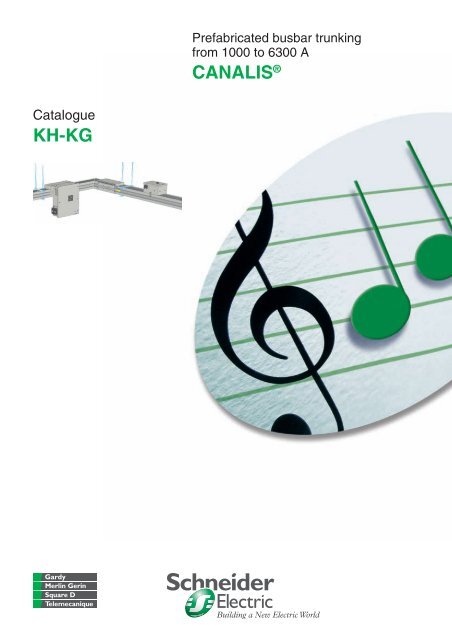
Catalogue<br />
<strong>KH</strong>-<strong>KG</strong><br />
Prefabricated busbar trunking<br />
from 1000 to 6300 A<br />
CANALIS ®
<strong>Schneider</strong> <strong>Electric</strong><br />
Contents<br />
CANALIS ® <strong>KH</strong>-<strong>KG</strong> from 1000 to 6300 A<br />
- Presentation 16<br />
- General 22<br />
- Description 24<br />
- Selection guide 30<br />
- Characteristics 31<br />
High power busbar trunking<br />
- References 34<br />
- Options 80<br />
- Dimensions 90<br />
- Procedure for ordering a made to measure equipment 109<br />
- Mounting 111
<strong>Schneider</strong> <strong>Electric</strong>
More than 50 000 km Canalis ® busbar trunking has been sold<br />
around the world.<br />
<strong>Schneider</strong> <strong>Electric</strong><br />
In decentralised distribution<br />
Canalis ® hits the high note<br />
CANALIS ® on its second world tour<br />
To better meet your needs, CANALIS ® extends its system solutions.<br />
b New low and medium power busbar trunking products.<br />
b Pre-equipped luminaires.<br />
b Strip lighting.<br />
b Specially designed cable trays.<br />
A total coordination with the <strong>Schneider</strong><br />
<strong>Electric</strong> system<br />
CANALIS ® is now part of a comprehensive offering of <strong>Schneider</strong> <strong>Electric</strong><br />
products designed to operate together. This concept covers all low and medium<br />
voltage electrical distribution components. The result is an optimised electrical<br />
installation with even higher performance through full electrical, mechanical and<br />
communication compatibility.<br />
With the new CANALIS ® range, you get a complete, tested distribution solution<br />
that complies with standards. It is perfectly suited to traditional applications<br />
(factories, warehouses, etc.) and to the distribution of electrical power from the<br />
incoming transformer on through to all types of loads in offices, commercial<br />
premises, laboratories, etc.<br />
CANALIS ® <strong>KH</strong> and <strong>KG</strong> is changing to<br />
provide you with...<br />
b … more flexibility. The adjustable section adapts to the worksite thus making<br />
sure you meet deadlines.<br />
b ease of connection with the adapted transformer and switchboard connections.<br />
b ... more assistance. Our teams will assist you throughout your project.
Distribution systems<br />
With CANALIS ® , you play all the<br />
right notes!<br />
<strong>Schneider</strong> <strong>Electric</strong> offers different distribution systems to fit your operating needs.<br />
Centralised distribution<br />
b For all continuous processes:<br />
v cement plants<br />
v oil and gas<br />
v petrochemicals<br />
v steel<br />
v paper, etc.<br />
b Centralised distribution offers:<br />
v continuity of service<br />
v combined distribution of power, control and monitoring circuits<br />
v supervision, etc.<br />
Our solutions:<br />
b Prisma Plus and Okken switchboards.<br />
Decentralised distribution<br />
b For manufacturing industries:<br />
v mechanical<br />
v textiles<br />
v lumber<br />
v injection moulding<br />
v electronics<br />
v pharmaceuticals<br />
v livestock, etc.<br />
b Decentralised distribution lets you:<br />
v design installations without layout details<br />
v upgrade without shutting down production<br />
v get systems up and running sooner thanks to faster installation<br />
v generate savings depending on the number of loads.<br />
Our solutions:<br />
Prisma Plus and Okken switchboards<br />
CanaliS ® b<br />
b<br />
busbar trunking.<br />
Combined distribution<br />
Where the advantages of both centralised and decentralised distribution are<br />
required.<br />
b Commercial and service buildings:<br />
v offices<br />
v stores<br />
v hospitals<br />
v exhibition halls, etc.<br />
b infrastructures:<br />
v airports<br />
v telecommunications<br />
v internet data centres<br />
v tunnels, etc.<br />
b industrial facilities:<br />
v pharmaceuticals<br />
v food processing, etc.<br />
Our solutions:<br />
Prisma Plus and Okken switchboards<br />
CanaliS ® b<br />
b<br />
busbar trunking.<br />
<strong>Schneider</strong> <strong>Electric</strong>
The CANALIS ® ,<br />
decentralized<br />
distribution concept<br />
<strong>Schneider</strong> <strong>Electric</strong><br />
With CANALIS ® , you play all the<br />
right notes!<br />
<strong>Electric</strong>al power available at all points,<br />
throughout the installation.<br />
Exclusive features of the <strong>Schneider</strong> <strong>Electric</strong> system<br />
Total coordination of the <strong>Schneider</strong> <strong>Electric</strong> system provides maximum safety of life<br />
and property, continuity of service, upgradeability and ease of installation.<br />
Total coordination is made easy by the tables in the “Selection Guide”. They help<br />
you chose the right combination of circuit breakers and busbar trunking. Product<br />
characteristics are checked by calculations and tests carried out in our laboratories.<br />
A competitive installation.<br />
Simplicity, upgradeability, safety and continuity of service and operation.<br />
Savings start with installation<br />
With tap-off points every 3 metres, Canalis busbar trunking reduces already<br />
installation costs.<br />
Given the low cost of adding new circuits, savings increase as the number of loads<br />
increases, a natural consequence of the growth of your business.<br />
Upgradeable during operation<br />
In decentralised distribution, evolving operating requirements and costs are<br />
integrated right from the start.<br />
b The addition, relocation or replacement of load equipment can be carried out<br />
quickly, without de-energising the supply trunking or shutting down operation<br />
b The cost of making such changes is greatly reduced:<br />
v loads are located close to supply points,<br />
v tap-off points are always available,<br />
v tap-units can be reused or new ones added quickly for load relocation or<br />
replacement needs.<br />
Reusable in the event of major changes<br />
When making major modifications to your installation, the existing trunking can be<br />
easily dismantled and reused.
Safety of life and property<br />
Example:<br />
Consequences of a fire in a 100 m 2 office with<br />
electrical distribution by cables.<br />
200 kg of cables (i.e. 20 kg of PVC) produces:<br />
b<br />
v<br />
v<br />
4400 m 3 of smoke,<br />
7,5 m 3 of hydrochloric acid,<br />
3,7 kg of corroded steel.<br />
Health<br />
CANALIS ® , in total harmony with<br />
the environment!<br />
With CANALIS ® , no risk in case of fire<br />
The busbar trunking has a low combustible load. Its construction uses very little<br />
consumable material and is halogen free.<br />
In the event of a fire, the busbar trunking does not emit any gas or toxic smoke.<br />
An inherent fire barrier, the busbar trunking helps prevent the propagation of a<br />
fire through partition walls and floors for a duration of 2 hours.<br />
Halogen-sensitive applications<br />
Public buildings (infrastructures, hospitals schools etc.).<br />
Buildings with evacuation difficulties (high-rises, ships, etc.) and service-activity<br />
buildings.<br />
Sensitive processes (production of electronic components, etc.).<br />
CANALIS ® b<br />
b<br />
b<br />
contains no PVCs<br />
When PVC’s burn, they produce large amounts of smoke that can be a serious<br />
safety hazard.<br />
b Reduced visibility<br />
v risk of panic<br />
v complicates rescue work<br />
b Smoke toxicity<br />
v hydrogen chloride gas (highly toxic)<br />
v carbon monoxide (danger of asphyxiation).<br />
CANALIS ® reduces the risk of exposure to electromagnetic<br />
fields<br />
According to the WHO (World Health Organisation), exposure to electromagnetic<br />
fields can be a health hazard starting at levels as low as 0.2 micro-Teslas and<br />
could represent a long-term risk of cancer. Some countries have created standards<br />
that stipulate limits (e.g. 0.2 NT at 1 metre in Sweden).<br />
All electrical conductors generate magnetic fields proportional to the distance<br />
between them. The design of CANAlIS ® busbar trunking with tightly spaced<br />
conductors in a metal enclosure helps to considerably reduce radiated<br />
electromagnetic fields.<br />
The electromagnetic field characteristics of CANAlIS ® busbar trunking are well<br />
defined and measurements show that they are far below potentially dangerous<br />
levels.<br />
<strong>Schneider</strong> <strong>Electric</strong>
Environment<br />
Example:<br />
1 kg of PVC generates 1 kg of waste<br />
Energy savings<br />
Type of Type of Type of Type of distribution<br />
of distribution<br />
of distribution<br />
of distribution<br />
of distribution<br />
of distribution<br />
of distribution<br />
of distribution<br />
of distribution<br />
of distribution<br />
of distribution<br />
of distribution<br />
of distribution<br />
of distribution<br />
of distribution<br />
of distribution<br />
of distribution<br />
Decentralised<br />
K s Ks Ks Ks Ks Ks : Ks : Ks : Ks : Ks : Ks : Kdiversity s : Kdiversity s : Kdiversity s : Kdiversity s : Kdiversity s : Kdiversity s : Kdiversity s : Kdiversity s : Kdiversity s : Kdiversity s : Kdiversity s : diversity s : diversity s : diversity s : diversity s : diversity s : diversity s : diversity s : diversity : diversity : diversity : diversity : diversity : diversity coefficient = 0,6 = 0,6 = 0,6 = 0,6 = 0,6 = 0,6 = 0,6 = 0,6 = 0,6 = 0,6 = 0,6 = 0,6 = 0,6 = 0,6 = 0,6 = 0,6 = 0,6 = 0,6 = 0,6 = 0,6 = 0,6<br />
Centralised<br />
K s Ks Ks Ks Ks Ks : Ks : Ks : Ks : Ks : Ks : Kdiversity s : Kdiversity s : Kdiversity s : Kdiversity s : Kdiversity s : Kdiversity s : Kdiversity s : Kdiversity s : Kdiversity s : Kdiversity s : Kdiversity s : diversity s : diversity s : diversity s : diversity s : diversity s : diversity s : diversity s : diversity : diversity : diversity : diversity : diversity : diversity coefficient = 0,6 = 0,6 = 0,6 = 0,6 = 0,6 = 0,6 = 0,6 = 0,6 = 0,6 = 0,6 = 0,6 = 0,6 = 0,6 = 0,6 = 0,6 = 0,6 = 0,6 = 0,6 = 0,6 = 0,6 = 0,6<br />
<strong>Schneider</strong> <strong>Electric</strong><br />
CANALIS ® , in total harmony with<br />
the environment!<br />
CANALIS ® is fully recyclable<br />
CANAlIS ® busbar trunking can be reused.<br />
CANAlIS ® busbar trunking is designed for a long service life and can easily be<br />
dismantled, cleaned and reused.<br />
All packaging materials can be recycled (cardboard or recyclable galvanized<br />
protection covers).<br />
All CANAlIS ® b<br />
b<br />
b<br />
b<br />
products are designed for safe end-of-life recycling. PVC, on the<br />
other hand, requires neutralisation of the hydrochloric acid produced using lime<br />
and generates dioxins that are extremely toxic.<br />
CANALIS ® helps conserve natural resources<br />
The depletion of raw materials (copper, plastics, etc.) is one of our ongoing<br />
concerns.<br />
For this reason, we have optimised the used of all materials used to make our<br />
busbar trunking.<br />
b Reduction of dangerous or polluting materials. We design our products to meet<br />
future European directives.<br />
b Reduction in the weight of insulating materials.<br />
b Reduction in the use of plastics for improved fire performance: less energy<br />
released during combustion, thereby limiting propagation and facilitating extinction<br />
(lower calorific value).<br />
CANALIS ® reduces your line losses by 40<br />
CANALIS ® divides your consumption of copper and insulation<br />
by a factor of three<br />
The cost of an electrical installation includes the initial investment for the<br />
equipment and its installation, the cost of maintenance and the cost of energy<br />
losses during operation.<br />
The cross-sections of our products are dimensioned to minimise the total cost of<br />
your installation over a 3-year period for medium intensity use (30 % load level, 5<br />
days a week and 10 hours a day).<br />
Example:<br />
30 m of CANALIS ® KS 250 A trunking equipped with ten 4-pole 25 A feeders.<br />
Conductors Insulation Consumption
A compact solution<br />
A simple and economical<br />
system<br />
CANALIS ® <strong>KH</strong>-<strong>KG</strong>, a display of<br />
advantages!<br />
b The compact size of Canalis <strong>KH</strong>-<strong>KG</strong> means it takes up very little space in the<br />
building:<br />
v used as a rising main, it takes up only a minimum of space,<br />
v used for horizontal distribution, it fits easily into the building’s structure (false<br />
floors, false ceilings, service shafts, etc).<br />
b Changes in direction have been designed to optimise the space taken up,<br />
contrary to an equivalent installation using cables which requires large bending<br />
radii.<br />
b Tap-off units, complete with protective devices, are fitted along the busbar<br />
trunking thus reducing the floor taken up by the electrical distribution swichboards.<br />
b The design study is easy to perform as it does not require a detailed layout of<br />
each load. Equipment choice is pre-determined and optimised.<br />
b Installing the busbar trunking requires 2 or 3 people only, for a time equivalent<br />
to that for installing cableways. The time normally needed for laying cables is<br />
therefore saved.<br />
b The tap-off units can be prepared in the workshop thus reducing on-site time.<br />
Their connection to the busbar trunking is done in a single plugging-on operation.<br />
b Installing busbar trunking lengths can be done as and when building work<br />
progresses, thus optimising on-site work and allowing possible unexpected events<br />
to be anticipated in advance.<br />
b Tap-off units, complete with protective devices, are fitted along the entire length<br />
of the busbar trunking thus reducing the floor area taken up by the electrical<br />
distribution switchboards.<br />
b<br />
It is also important to note that busbar trunking is a factory tested solution,<br />
meaning the time needed for inspecting connections is reduced (visual inspection<br />
of tightening torque).<br />
<strong>Schneider</strong> <strong>Electric</strong>
Complete safety<br />
Operating continuity<br />
A large range of tap-off units<br />
<strong>Schneider</strong> <strong>Electric</strong><br />
CANALIS ® <strong>KH</strong>-<strong>KG</strong>, a display of<br />
advantages!<br />
b Busbar trunking temperature rise and short-circuit withstand are known and,<br />
independent of the installation. Coordination of the <strong>Schneider</strong> <strong>Electric</strong> system<br />
results in complete control of the electrical network.<br />
b Installation standards UTE C 15-105 chapter B.6.2 and IEC 60 364 chapter<br />
5.523.6 stipulate that above 4 parallel cables, it is preferable to use busbar<br />
trunking. Paralleling many cables leads to uneven distribution of currents and the<br />
risk of abnormal temperature rise.<br />
b The busbar trunking and tap-off units are designed to guarantee the safety of<br />
personnel and equipment:<br />
v plug-in connections to silver-plated copper bars,<br />
v bolted connections with tightening torque guaranteed by torque nuts,<br />
v foolproof system to avoid the risk of assembly errors,<br />
v access to live parts have IPxxC protection (2,5 mm wire diameter).<br />
Its metal enclosure and protection degree protect the busbar trunking from all<br />
external aggressions (corrosion, rodents, etc).<br />
When working on the electrical installation, the busbar trunking provides immediate<br />
readability of the electrical circuit thus allowing the appropriate zone to be quickly<br />
identified.<br />
Tap-off units can be plugged-on and off without the need for a shutdown; service<br />
continuity is thus irreproachable.<br />
The quality of the electrical contacts guarantees maintenance free operating<br />
continuity.<br />
They cover all you needs<br />
CANALIS ® b<br />
v<br />
<strong>KH</strong>-<strong>KG</strong> tap-off units: from 50 to 1000 A,<br />
b They offer circuit breaker or fuse protection.<br />
This offer includes tap-off units that can be fitted with the Transparent Ready<br />
system:<br />
v they monitor your installation to avoid overloads, thus ensuring service<br />
continuity,<br />
v they provide metering to allow accurate management of your electrical<br />
distribution network (allocation of costs to each consumer).
Play all the world’s music with<br />
CANALIS ® !<br />
CANALIS ® on its second world tour<br />
To better meet your needs, Canalis extends its system solutions.<br />
b New low and medium power busbar trunking products.<br />
b Pre-equipped luminaires.<br />
b<br />
Strip lighting.<br />
10<br />
<strong>Schneider</strong> <strong>Electric</strong>
Infrastructure<br />
Airports<br />
Marine<br />
Metro<br />
Other infrastructure<br />
Play all the world’s music with<br />
CANALIS ® !<br />
Name Lighting and low current Medium<br />
current<br />
High<br />
current<br />
KDP KBA KBB KN KS KT <strong>KH</strong><br />
Country<br />
Paris Airport b b b b b b France<br />
Cairo Airport b Egypt<br />
Heathrow airport b b b United Kingdom<br />
Hong-Kong Airport b China<br />
Landvetter airport b b Sweden<br />
Arlanda Airport b b b Sweden<br />
Satelite Barajas b Spain<br />
Brussels Airport b Belgium<br />
Frankfurt Airport b Germany<br />
Chantier de l’Atlantique b b France<br />
Meyerwerft b b Germany<br />
Sea Launch b Norway<br />
Oseberg b Norway<br />
Guanghzou Underground b China<br />
London Underground b United Kingdom<br />
Madrid Underground b b Spain<br />
Singapore Underground b Singapore<br />
Brussels Underground b Belgium<br />
Alexandria library b b Egypt<br />
Exhibition centre in Sushou b b China<br />
CERN b b Switzerland<br />
Stade de France b b France<br />
L’Opera de La Bastille Paris b France<br />
Exhibition centre in Dusseldorf b b Germany<br />
Exhibition centre in Koln b Germany<br />
Exhibition centre in Frankfurt b b Germany<br />
<strong>Schneider</strong> <strong>Electric</strong> 11
Tertiary<br />
Offices<br />
Internet Data Center<br />
Play all the world’s music with<br />
CANALIS ® !<br />
Name Lighting and low current Medium<br />
current<br />
High<br />
current<br />
KDP KBA KBB KN KS KT <strong>KH</strong><br />
Country<br />
Air Frankrijk (headquarters) b b France<br />
Allianz b b b Germany<br />
Axa b b France<br />
Chamber of Commerce b b Luxembourg<br />
Commerz Bank b b b Germany<br />
Lexel b b b Sweden<br />
Telefonica b b b Spain<br />
Trade Center b b b Spain<br />
RDC-tower b b Tunisia<br />
Rabobank b b Netherlands<br />
Fortis Bank b b b Belgium<br />
National Banc b Belgium<br />
Banco commercial Portugués b b Portugal<br />
Colt b b b France<br />
Digiplex b b Sweden<br />
IBM b b b b b Spain, Italy<br />
MCI-Worldcom b b b b Italy, United kingdom<br />
I-net b Italy<br />
Exodus b France<br />
UU-net b Norway<br />
IX Europol b Germany<br />
Hotels and restaurants<br />
Hyatt b Tunisia<br />
Soldeo Andorra<br />
Mc Donald’s b France<br />
Radisson SAS Stansted Airport b United kingdom<br />
Soldeo Andorra Hotel b b Spain<br />
Children Clinic b b Sweden<br />
Brussels University Hospital b Belgium<br />
Derby Hospital b b United kingdom<br />
Oran Hospital b b Algeria<br />
St-Joseph Hospital b France<br />
Stockholm Hospital b Sweden<br />
Laroboisiere Hospital b France<br />
Michalon Hospital b b France<br />
Aken Hospital b b Germany<br />
Dusseldorf Hospital b b Germany<br />
Supermarkets and hypermarkets<br />
Alcampo b b b Spanje<br />
Auchan b b b b b b b World<br />
B&Q b b b United kingdom<br />
Carrefour b b b b b b World<br />
Coop b b b Italy<br />
Fnac b b Spain, France<br />
Ikea b b b b b b China, Spain, France,<br />
Sweden<br />
Mark & Spencer b b Belgium, Spain,<br />
United kingdom<br />
Fields b b Danemark<br />
City 2 b Belgium<br />
12<br />
<strong>Schneider</strong> <strong>Electric</strong>
Industry<br />
Auto-industrie<br />
Other industries<br />
Aerospace industry<br />
Food-processing industry<br />
<strong>Electric</strong>ity<br />
Watch-making<br />
Micro electronics<br />
Lead industry and water treatment<br />
Industrial technology<br />
Telephony<br />
Textile industry<br />
Play all the world’s music with<br />
CANALIS ® !<br />
Name Lighting and low current Medium<br />
High<br />
current<br />
current<br />
KDP KBA KBB KN KS KT <strong>KH</strong><br />
Country<br />
BMW b b b b b Italy / Germany<br />
Citroën b b b b b b b China, Spain, France<br />
Daewo b b South Korea<br />
Dacia b b b b b b Romania<br />
Iveco b b b b b Spain, Italy<br />
Peugeot b b b b b China, Spain, France<br />
Nissan b b b b b b Spain<br />
Renault b b b b b b Spain, France,<br />
Czech Republic<br />
Seat b Spain<br />
Valéo b b b b China,France, Italy,<br />
Poland<br />
Volkswagen / Audi b b b b Spain, Germany, Belgium<br />
Ford b b b b Spain, Germany, Belgium<br />
Opel b Belgium, Germany<br />
Volvo b Belgium<br />
Mercedes b Germany, Italy<br />
Daf b Belgium, Netherland<br />
Kia b South Korea<br />
Airbus b b b b Italy<br />
Coca-Cola b b b Spanje, Italy, Belgium<br />
Danone b b b b World<br />
Pasquier b b France<br />
Legrand b France, Turkey<br />
EDF b France<br />
Rolex b b b b Zwitserland<br />
Intel b b b b Ireland<br />
ST Micro-électronique b b b b b France<br />
Grundfos b b China, Danemark<br />
Bosch b b b China, Germany, Italy<br />
Phillips b Netherlands<br />
Nokia b b Sweden<br />
Motorola b Spain<br />
Louis Vuitton b b b Spain<br />
Delta b b Israel<br />
Picanol b Belgium<br />
<strong>Schneider</strong> <strong>Electric</strong> 13
Technical files<br />
With the CANALIS ® tools and<br />
services, let us compose your<br />
project!<br />
The technical files have been compiled from completed contract and provide<br />
answers to question concerning the installation of Canalis busbar trunking in<br />
specific business sectors.<br />
In data centers<br />
In exhibition centres<br />
In shopping centres<br />
In electronics factories<br />
In tiles factories<br />
In car plants<br />
In livestock buildings<br />
In greenhouses<br />
In logistic centres<br />
On cruise ships<br />
In garages<br />
14<br />
<strong>Schneider</strong> <strong>Electric</strong>
Work-out your solution<br />
together<br />
After-sales<br />
service<br />
One-site<br />
instruction and<br />
installation<br />
With the CANALIS ® tools and<br />
services, let us compose your<br />
project!<br />
Our teams are available to provide customers with technical assistance throughout<br />
the installation of their projects.<br />
b Design of electrical distribution architectures:<br />
design of decentralised transport and distribution systems,<br />
v technical and financial optimisation of busbar trunking design project,<br />
v transformer / switchboard link,<br />
v installation coordination and discrimination.<br />
b<br />
v<br />
v<br />
v<br />
Full installation drawings:<br />
3D autocad drawings with cooresponding parts list,<br />
2D drawings with dimensions,<br />
Detailed connection drawings.<br />
b Site supervision and commissioning assistance.<br />
b Training for designers and contractors.<br />
Project<br />
launch<br />
Project<br />
management<br />
Technical<br />
support<br />
CanBrass<br />
drawing<br />
Production<br />
Autocad<br />
drawing<br />
<strong>Schneider</strong> <strong>Electric</strong> 15
Presentation<br />
Range CANALIS ® KDP CANALIS ® KBA<br />
Run components<br />
Degree of protection IP55 IP55<br />
Number of ciruits 1 1<br />
Rating 20 A 25 and 40 A<br />
Tap-off intervals 1200 - 1350 - 1500 - 2400 - 2700 en 3000 mm 500 - 1000 and 1500 mm<br />
Standard lengths 24 or 192 m 2 and 3 m<br />
Finish - Galvanised steel<br />
Maximum distance between fixing points 0,33 m 3 m<br />
KDP-KBA-KBB tap-off units<br />
Rating 10 and 16 A 10 and 16 A<br />
Options<br />
Panorama of CANALIS ® KDP<br />
and CANALIS ® KBA<br />
Lighting distribution<br />
- White RAL 9010<br />
- Bus conductor<br />
- -<br />
16<br />
<strong>Schneider</strong> <strong>Electric</strong>
Presentation Panorama of CANALIS ® KDP<br />
and CANALIS ® KBA<br />
Lighting distribution<br />
CANALIS ® KBB CANALIS ® KBX<br />
IP55 IP20<br />
1 or 2 1<br />
25 and 40 A 25 A<br />
500 and 1000 mm -<br />
2 and 3 m 1,53 and 3,06 m<br />
Galvanised steel White<br />
5 m 3 m<br />
10 and 16 A<br />
White RAL 9010 -<br />
Bus conductor -<br />
Clean earth -<br />
<strong>Schneider</strong> <strong>Electric</strong> 17
Presentation Panorama of CANALIS ® range<br />
Power distribution<br />
Range CANALIS ® KN<br />
Run components<br />
Degree of protection IP55<br />
Polarity 3L + N + PE<br />
Rating 40, 63, 100 and 160 A<br />
Tap-off intervals 500 - 1000 or 3000 mm<br />
Standard lengths 3 m<br />
Finish White RAL 9001<br />
Maximum distance between fixing points 3 m<br />
Tap-off units<br />
Rating Plug-in 16 to 63 A<br />
Bolt-on<br />
Option<br />
Remote control conductor<br />
18<br />
<strong>Schneider</strong> <strong>Electric</strong>
Presentation Panorama of CANALIS ® range<br />
Power distribution<br />
CANALIS ® KS CANALIS ® KS Rising mains<br />
IP55 IP55<br />
3L + N + PE 3L + N + PE<br />
100, 160, 250, 400, 500, 630, 800 and 1000 A 100, 250, 400, 500, 630, 800 and 1000 A<br />
500 mm (1000 mm on each face) 500 mm<br />
3 and 5 m Defined by the floor pitch<br />
White RAL 9001 White RAL 9001<br />
3 m Defined by the floor pitch<br />
25 to 400 A 25 to 400 A<br />
- -<br />
<strong>Schneider</strong> <strong>Electric</strong> 19
Presentation<br />
all products of <strong>KH</strong>-<br />
<strong>KG</strong> are halogen<br />
free and therefore<br />
no toxic gas or<br />
smoke is emitted.<br />
Busbar trunkings<br />
with an inherent<br />
fire barrier, help<br />
prevent the<br />
propagation of<br />
a fire through<br />
partition walls and<br />
floors for a duration<br />
of 2 hours.<br />
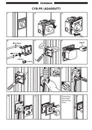
CANALIS ® <strong>KH</strong>-<strong>KG</strong><br />
from 1000 to 6300 A<br />
For horizontal and vertical<br />
distribution and transport<br />
A high protection degree<br />
The high protection degree of Canalis ® <strong>KH</strong>-<strong>KG</strong> busbar<br />
trunking make it suitable for installation in all types of<br />
buildings.<br />
IP31 garantees that the busbar trunking is protected<br />
against small foreign bodies, diametre greater than or equal<br />
to 2,5 mm and against vertically falling drops of water.<br />
Canalis ® b<br />
b<br />
<strong>KH</strong>-<strong>KG</strong> meets the sprinklertest. This implies<br />
a garanteed operation for 90 minutes when exposed to a<br />
vertical or horizontal sprinklerjet.<br />
b<br />
IK-waarde 08 garantees the resistance of the busbar<br />
trunking system against mechanical shocks.<br />
The letter C next to the IP values assure the absolute<br />
safety of the maintenance crew.<br />
Easy manipulation<br />
The Canalis ® busbar trunking system can be easily<br />
manipulated thanks to the aluminium conductors.<br />
The busbar trunking systems with copper conductors are<br />
40% heavier for the same rating.<br />
The low weight of the Canalis ® <strong>KH</strong>-<strong>KG</strong> simplifies its<br />
installation which is time reducing.<br />
The installation can be done by a small team with limited<br />
tools.<br />
20<br />
schneider <strong>Electric</strong>
Presentation CANALIS ® <strong>KH</strong>-<strong>KG</strong><br />
from 1000 to 6300 A<br />
For horizontal and vertical<br />
distribution and transport<br />
schneider <strong>Electric</strong> 21
General<br />
1 2<br />
Straight lengths<br />
1000 to 6300 A.<br />
3 or 4 live conductors in aluminium (<strong>KH</strong>) or in copper (<strong>KG</strong>).<br />
3 and 5 metre lengths.<br />
canalis <strong>KH</strong>F<br />
<strong>KH</strong>F-26<br />
3L +1/2N+PE<br />
Ui = 750 U ~ IP31(IEC 529)<br />
Telemecanique<br />
EN 60439-2<br />
NF C63-411<br />
VDE 0660-5<br />
N L3 L2 L1<br />
Nulleiter T S R<br />
ÖVE<br />
SYM : <strong>KH</strong>F-26EA1A<br />
REP<br />
DIM : 500<br />
AFF : 10751<br />
MADE : 1B 92/44<br />
310621-B<br />
CANALIS ® <strong>KH</strong>-<strong>KG</strong> from 1000 to 6300 A<br />
For horizontal and vertical distribution<br />
and transport<br />
22 <strong>Schneider</strong> <strong>Electric</strong><br />
EN 60439-2<br />
canalis <strong>KH</strong>F<br />
NF C63-411<br />
VDE 0660-5<br />
<strong>KH</strong>F-26<br />
ÖVE<br />
3L +1/2N+PE<br />
Ui = 750 U ~ IP31(IEC 529)<br />
elemecanique<br />
T<br />
SYM : <strong>KH</strong>F-26EA1A<br />
REP<br />
DIM : 500<br />
AFF : 10751<br />
MADE : 1B 92/44<br />
310621-B<br />
Telemecanique<br />
R<br />
L1<br />
S<br />
L2<br />
T<br />
L3<br />
Nulleiter<br />
N<br />
Feed units<br />
For connecting <strong>KH</strong> and <strong>KG</strong> busbar<br />
to the transformer terminals<br />
or the switchboard connections.<br />
canalis <strong>KH</strong>F<br />
<strong>KH</strong>F-26<br />
3L +1/2N+PE<br />
Ui = 750 U ~ IP31(IEC 529)<br />
Telemecanique<br />
EN 60439-2<br />
NF C63-411<br />
VDE 0660-5<br />
Telemecanique<br />
N L3 L2 L1<br />
Nulleiter T S R<br />
ÖVE<br />
SYM : <strong>KH</strong>F-26EA1A<br />
REP<br />
DIM : 500<br />
AFF : 10751<br />
MADE : 1B 92/44<br />
310621-B
3 5<br />
Additional components<br />
For adapting the busbar trunking<br />
to the contours of the installation<br />
(changes in direction, level, obstacles, etc.).<br />
canalis <strong>KH</strong>F<br />
EN 60439-2<br />
NF C63-411<br />
VDE 0660-5<br />
<strong>KH</strong>F-26<br />
3L +1/2N+PE<br />
Ui = 750 U ~ IP31(IEC 529)<br />
N L3 L2 L1<br />
Nulleiter T S R<br />
ÖVE<br />
SYM : <strong>KH</strong>F-26EA1A<br />
REP<br />
DIM : 500<br />
AFF : 10751<br />
MADE : 1B 92/44<br />
310621-B<br />
canalis <strong>KH</strong>F<br />
<strong>KH</strong>F-26<br />
3L +1/2N+PE<br />
Ui = 750 U ~ IP31(IEC 529)<br />
N L3 L2 L1<br />
Nulleiter T S R<br />
EN 60439-2<br />
NF C63-411<br />
VDE 0660-5<br />
ÖVE<br />
SYM : <strong>KH</strong>F-26EA1A<br />
REP<br />
DIM : 500<br />
AFF : 10751<br />
MADE : 1B 92/44<br />
310621-B<br />
Tap-off units<br />
Bolt-on or plug-in tap-off<br />
units fitted with fuse isolators,<br />
fuse switches or circuit-breakers.<br />
<strong>Schneider</strong> <strong>Electric</strong> 23<br />
CANALIS <strong>KH</strong><br />
Telemecanique
Description<br />
General<br />
L1<br />
L2<br />
L3<br />
N<br />
<strong>CANALIS®</strong> <strong>KH</strong>-<strong>KG</strong> from 1000 to 6300 A<br />
For horizontal and vertical distribution<br />
and transport<br />
<strong>KH</strong> and <strong>KG</strong> busbar trunking lengths are designed to carry an distribute high power, in normal operating conditions, in<br />
industrial, commercial or service buildings.<br />
The conductors are made of aluminium (<strong>KH</strong>F) for currents of 1000 to 5500 A, divided into 11 ratings, or copper (<strong>KG</strong>F)<br />
for currents of 1600 to 6300 A, divided into 5 ratings.<br />
Live conductors are said to be”sandwiched”, as show on<br />
the drawing opposite. This configuration reduces<br />
eletrodynamic forces in the event of short-circuits.<br />
Furthermore, the conductors are held in place by isolators,<br />
mechanically independent from the sheet steel structure,<br />
which counteracts these forces. The conductors are<br />
insulated by a polyester film. The neutral conductor is<br />
indentified by a blue ring inside the busbar trunking.<br />
The top and bottom of the casing comprises covers in grey<br />
Ral 7032 paint finished sheet steel with perforations. The<br />
sides are made of galvanised sheet steel C-shaped rails.<br />
These are use as protective conductors and every joint is<br />
made in such a way as to ensure efficient conductivity.<br />
A system with enforced protective conductors can be<br />
produced ( see enforced protective conductor and options).<br />
These busbars trunking lengths are ventilated, which enables optimum usage of the conductive part.<br />
They are designed to be flat-mounted, though it is possible to mount them edgewise. In this case, natural convection is no longer possible,<br />
and the busbar trunking must be derated (see characteristics on page 31).<br />
Straight lengths<br />
There are two types of straight length:<br />
p Type EA, designed as feeder trunking. Tap-offs can be made at each joint. These straight lengths are manufactured in<br />
3 or 5 metre sizes. They can be made to measure any length between 1 and 3 metres.<br />
p Type ED, for distribution. Tap-offs can be made at joints as well as along the length using tap-off outlets (3 for a 3 metre<br />
length, 5 for a 5 metre length).<br />
These outlets are fitted with shutters preventing foreign matter entering when no unit is fitted. With the shutters open,<br />
the IP 2 degree of protection is maintained.<br />
Connecting straight lengths<br />
N L3 L2 L1<br />
Nulleiter T S R<br />
The electrical connection of lengths is performed by bolting the<br />
lengths together. Tin plates are welded at the ends of the<br />
conductors.<br />
The plates are bolted together. When there are several bars<br />
per phase, bars which have the same polarity are connected<br />
using “equipotential blocks”. The bolts must tightened to a<br />
torque of 4,5 daN.m. This torque is automatically reached<br />
when the breakable head of the bolt snaps off.<br />
This type of jointing is used for mounting fixed tap-off units<br />
(type SB).<br />
It is therefore possible to add tap-off units to an existing<br />
installation without modifying the lengths.<br />
24 <strong>Schneider</strong> <strong>Electric</strong><br />
canalis <strong>KH</strong>F<br />
<strong>KH</strong>F-26<br />
3L +1/2N+PE<br />
Ui = 750 U ~ IP31(IEC 529)<br />
Telemecanique<br />
EN 60439-2<br />
NF C63-411<br />
VDE 0660-5<br />
ÖVE<br />
SYM : <strong>KH</strong>F-26EA1A<br />
REP<br />
DIM : 500<br />
AFF : 10751<br />
MADE : 1B 92/44<br />
310621-B
Description<br />
<strong>CANALIS®</strong> <strong>KH</strong>-<strong>KG</strong> from 1000 to 6300 A<br />
For horizontal and vertical distribution<br />
and transport<br />
<strong>Electric</strong>al contacts<br />
<strong>KH</strong>-<strong>KG</strong> busbar trunking uses two types of contacts:<br />
- Bolded contacts for the connection of the lengths and bold-on tap-off units.<br />
The surface is tined.<br />
- Jaw contacts for the connection of the plug-in tap-off units. These contacts have a surface of silvered copper.<br />
Expansions<br />
p Expansion of the straight lengths<br />
All lengths of 3 m and more are fitted with an expansion joint wich absorbs the differential expansion between the busbars and the<br />
casing.<br />
The expansion joints are located in the centre of the 3 and 5 metre trunking lengths, and are composed of flexible laminates in the same metal<br />
as the conductors. The set of busbars are clamped at each end of the trunking length to orientate the expansion towards the expansion joint.<br />
p Building expansion unit<br />
This is a straight length available 3 m length only. This unit has a double expansion joint which allow for the differential<br />
expansion between the busbar and the casing and between the casing and the building.<br />
It is mounted across a building expansion joint.<br />
It is fixed on either side of the building expansion joint in order to firmly attach it to the building.<br />
This enables any force to be diverted to the expansion joint of the trunking length.<br />
p Fire barrier<br />
<strong>KH</strong> or <strong>KG</strong> busbar trunking lengths (exept ED lengths) can have a 2-hour rating fire barrier. (CSTB report N°759389C).The<br />
fire barrier must be positioned in the centre of the floor slab or wall in order to prevent the spreading of fire to other levels.<br />
Connections<br />
There are two types of units for connecting trunking to various types of equipment (transformer, distribution boards,<br />
circuit-breakers, etc.).<br />
Flange unit<br />
End feed unit<br />
canalis <strong>KH</strong>F<br />
EN 60439-2<br />
NF C63-411<br />
VDE 0660-5<br />
<strong>KH</strong>F-26<br />
3L +1/2N+PE<br />
Ui = 750 U ~ IP31(IEC 529)<br />
SYM : <strong>KH</strong>F-26EA1A<br />
REP<br />
DIM : 500<br />
AFF : 10751<br />
MADE : 1B 92/44<br />
N L3 L2 L1<br />
Nulleiter T S R<br />
ÖVE<br />
310621-B<br />
canalis <strong>KH</strong>F<br />
<strong>KH</strong>F-26<br />
3L +1/2N+PE<br />
Ui = 750 U ~ IP31(IEC 529)<br />
N L3 L2 L1<br />
Nulleiter T S R<br />
The flange unit is reserved for sizes <strong>KH</strong>F-14, 16 and 18<br />
and <strong>KG</strong>F-16. It provides a simple solution for any<br />
connection at the trunking run.<br />
The bars are always made of copper, no matter what<br />
type of busbar trunking (<strong>KH</strong>F or <strong>KG</strong>F) to which the end<br />
cover is attached.<br />
Whether the trunking is 3P or 3P + N + PE, the flanged<br />
unit is always 3P + N + PE.<br />
These units connect trunking from the end, from below or<br />
from above.<br />
A wide variety of type of connection is offered by varying<br />
the orientation and fixing centres of the bars as well as the<br />
position of the units on the trunking.<br />
The busbars are always copper.<br />
<strong>Schneider</strong> <strong>Electric</strong> 25<br />
EN 60439-2<br />
NF C63-411<br />
VDE 0660-5<br />
ÖVE<br />
SYM : <strong>KH</strong>F-26EA1A<br />
REP<br />
DIM : 500<br />
AFF : 10751<br />
MADE : 1B 92/44<br />
310621-B
Description<br />
Connections (continued)<br />
Cable end feed unit<br />
End cover<br />
Directional changes<br />
<strong>CANALIS®</strong> <strong>KH</strong>-<strong>KG</strong> from 1000 to 6300 A<br />
For horizontal and vertical distribution<br />
and transport<br />
canalis <strong>KH</strong>F<br />
EN 60439-2<br />
NF C63-411<br />
VDE 0660-5<br />
<strong>KH</strong>F-26<br />
3L +1/2N+PE<br />
Ui = 750 U ~ IP31(IEC 529)<br />
N L3 L2 L1<br />
Nulleiter T S R<br />
ÖVE<br />
SYM : <strong>KH</strong>F-26EA1A<br />
REP<br />
DIM : 500<br />
AFF : 10751<br />
MADE : 1B 92/44<br />
310621-B<br />
canalis <strong>KH</strong>F<br />
<strong>KH</strong>F-26<br />
3L +1/2N+PE<br />
Ui = 750 U ~ IP31(IEC 529)<br />
N L3 L2 L1<br />
Nulleiter T S R<br />
These units are available for up to <strong>KH</strong>F-38 and <strong>KG</strong>F-36.<br />
They connect the trunking via copper or aluminium cables,<br />
fitted with lugs.<br />
They can be mounted either above or below the trunking,<br />
and at either end of the run.<br />
The busbar are always copper.<br />
This protects and insulates the conductors and is assembled<br />
on the last trunking length. It can be fitted with a tap-off unit<br />
which is fixed to the joint.<br />
Edgewise / flat for changing the trunking run direction.<br />
There are three types:<br />
p Flat or edgewise elbows, upwards of downwards, to the<br />
right or left.<br />
p Zed units, 3, 4 or 5 limbs.<br />
Flat or edgewise to modify the centre-line of the busbar<br />
trunking run upwards, or downwards, to the right or the left<br />
without changing the trunk run direction.<br />
p Edgewise / flat for changing the trunking run direction.<br />
26 <strong>Schneider</strong> <strong>Electric</strong><br />
EN 60439-2<br />
NF C63-411<br />
VDE 0660-5<br />
ÖVE<br />
SYM : <strong>KH</strong>F-26EA1A<br />
REP<br />
DIM : 500<br />
AFF : 10751<br />
MADE : 1B 92/44<br />
310621-B<br />
canalis <strong>KH</strong>F<br />
EN 60439-2<br />
NF C63-411<br />
VDE 0660-5<br />
<strong>KH</strong>F-26<br />
3L +1/2N+PE<br />
Ui = 750 U ~ IP31(IEC 529)<br />
N L3 L2 L1<br />
Nulleiter T S R<br />
ÖVE<br />
SYM : <strong>KH</strong>F-26EA1A<br />
REP<br />
DIM : 500<br />
AFF : 10751<br />
MADE : 1B 92/44<br />
310621-B
Description <strong>CANALIS®</strong> <strong>KH</strong>-<strong>KG</strong> from 1000 to 6300 A<br />
For horizontal and vertical distribution<br />
and transport<br />
Riser lengths<br />
Riser lengths<br />
Fixing brackets<br />
p This is the basic unit, of a similar design to horizontal<br />
trunking, and includes:<br />
- a differential busbar/casing expansion joint for any<br />
length,<br />
- a 2 hour rating fire barrier (CSTB test report N° 759389X),<br />
at the point where the trunking passes through the<br />
floor slab.<br />
The length is generally equal to the height of the floor<br />
to which it is to be fitted.<br />
The reference label should always be located on the<br />
top left of each length. This enables the tap-off unit<br />
covers to be opened downwards.<br />
There are two types of riser lengths:<br />
p Type VA<br />
Designed for use as feeder trunking without tap-off<br />
outlets between joints.<br />
p Type VD<br />
Designed for use as distribution trunking with two tapoff<br />
outlets between joints.<br />
Wall support brackets<br />
There are two versions:<br />
p For bottom thrust and intermediate thrust units.<br />
These receive flanges on the lengths and enable the fixing<br />
and adjustement of the trunking in relation to the wall. The<br />
correct installation of these brackets ensure the accurate<br />
positioning of the fire barriers along the rising mains. It is<br />
imperative that the fixing dimensions are strictly observed.<br />
p For the top suspension unit<br />
This bracket, whose support plate is not slotted receives<br />
the adjustement screws for the length.<br />
Guide brackets<br />
These are designed to guide the colomn in relation to the<br />
wall.<br />
<strong>Schneider</strong> <strong>Electric</strong> 27
Description <strong>CANALIS®</strong> <strong>KH</strong>-<strong>KG</strong> from 1000 to 6300 A<br />
For horizontal and vertical distribution<br />
and transport<br />
1 - Riser length<br />
2 - Bottom thrust unit<br />
3 - Intermediate thrust unit<br />
4 - Top suspension unit<br />
5 - Feed unit<br />
6 - End cover<br />
7 - End cover<br />
8 - Fixing brackets<br />
9 - Power supplied by Canalis<br />
Top suspension unit<br />
This is the last riser length. It is of indentical design to the other riser lengths, and is fitted with a device for removing<br />
riser lengths during operation.<br />
This device is composed of 2 flanges on which two H14 x 130 screws act as jacks resting on the wall support brackets.<br />
Bottom thrust unit and intermediate thrust units<br />
The bottom thrust unit is used to support the riser length.<br />
It is of identical design to the other riser lengths, and is fitted with two fixing brackets.<br />
When the riser length reaches a weight of 2 tonnes, the bottom thrust unit must be replaced with an intermediate thrust<br />
unit, and so every 2 tonnes.<br />
The intermediate thrust unit is fitted with a double expansion joint allowing for differential expansion between the<br />
conductors and the casing, and casing and the building. It is fitted with two fixing brackets.<br />
These units must be installed with precision to ensure the correct positioning of the fire barriers in relation to the<br />
building.<br />
Installing rising mains<br />
Installing lengths from the top<br />
p Store all the equipment at the top of the building.<br />
p Install the wall brackets for the bottom thrust unit (and the intermediate thrust unit(s) if required).<br />
The wall bracket for the top suspension unit should be mounted last. Its installation is linked to the position of the top<br />
suspension unit bolts, the stacking of tolerances to a great height may cause the position of these bolts to vary slightly.<br />
p Position the fixing pins of the guide brackets.<br />
p Using a winch (or any other type of lifting gear); lower<br />
the bottom thrust unit down the riser duct and fix it to the<br />
bracket. Check that the fire barrier is correctly positioned.<br />
p Lower the next length, then attach it mechanical and<br />
electrically to the bottom thrust unit.<br />
p Repeat the operation for the following units, finishing<br />
with the top suspension unit.<br />
p Mount the end cover.<br />
p Fix the wall bracket for the top suspension unit.<br />
p Mount the guide brackets.<br />
p Assemble the tap-off units.<br />
p Free the intermediate thrust unit(s) (see the label on the<br />
uit).<br />
p Mount the feed unit.<br />
Installing lengths from the bottom<br />
p Store all the equipment on the bottom floor, accessible to materials handling equipment.<br />
p Install the wall brackets for the bottom thrust unit (and the<br />
intermediate thrust unit(s) if required). The wall brackets of<br />
the top suspension unit should be mounted last. Its<br />
installation is linked to the position of the top suspension<br />
unit bolts, the stacking of tolerances to a great height may<br />
cause the position of the bolts to vary slightly..<br />
p Position the fixing pins for the guide brackets.<br />
p Mount the end cover on the top suspension unit..<br />
p Using a winch (or any other type of lifting gear), hoist the<br />
top suspension unit to a height sufficient to enable<br />
mechanical and electrical assembly of the next unit.<br />
p Now hoist the two assembled units as above. Next<br />
assemble a third length…. And so on until the bottom<br />
thrust uit has been connected (the whole length of the<br />
rising main is now totally suspended by the winch).<br />
p Fix the bottom thrust unit to its wall bracket.<br />
p Check that the fire barrier is correctly positioned.<br />
p Mount the guide brackets.<br />
p Fix the wall bracket for the top suspension unit.<br />
p Assemble the tap-off units<br />
p Free the intermediate thrust unit(s) (see label on the length).<br />
p Mount the feed unit.<br />
28 <strong>Schneider</strong> <strong>Electric</strong>
Description<br />
Tap-off units<br />
Bolt-on tap-off units<br />
Plug-in tap-off units<br />
<strong>CANALIS®</strong> <strong>KH</strong>-<strong>KG</strong> from 1000 to 6300 A<br />
For horizontal and vertical distribution<br />
and transport<br />
They can be mounted on the left or the right of the trunking<br />
joint. It is possible to mount two tap-off units on the same<br />
joint.<br />
These bolt-on tap-off units are available in rating up to 1000 A<br />
They can be fitted with either UTE or VDE fuse and have:<br />
- either a fusible off-load isolator which operates as the cover<br />
is opened,<br />
- or an on-load switch and fuse carriers.<br />
These units plug-in to the tap-off outlets on straight<br />
trunking lengths.<br />
Each tap-off outlet has six apertures, five to receive the<br />
conductors (3 phase + neutral + earth). The sixth has a<br />
location device to ensure correct polarity and positioning of<br />
the unit.<br />
These plug-in tap-off uits are available in ratings up to 630 A.<br />
They can be fitted with:<br />
- UTE / VDE fusible off-load isolator ensuring isolation<br />
when the cover is opened.<br />
- fixing for a Merlin Gerin circuit-breaker, type NS, with<br />
rotary or electric control.<br />
<strong>Schneider</strong> <strong>Electric</strong> 29<br />
CANALIS <strong>KH</strong><br />
Telemecanique
Selection guide<br />
<strong>CANALIS®</strong> <strong>KH</strong>-<strong>KG</strong> from 1000 to 6300 A<br />
For horizontal and vertical distribution<br />
and transport<br />
Determining the rating according to the temperature rise<br />
The nominal current of a busbar trunking, represents the maximum intensity of the constant current which the trunking can<br />
continuously support, when the average ambient temperature is 35 °C, and in accordance with normal temperature rise.<br />
Determining the rating according to the temperature rise consist of selecting the busbar trunking rating immediately<br />
above the operating current of the installation. However, the intensity of the current which crosses a busbar trunking<br />
generally varies continuously. The operating current is therefore defined as that of the constant current which produces<br />
the same thermal effects as the actual current.<br />
It is sometimes difficult to determine the operating current, especially when no reading has been made on the existing<br />
installation or an equivalent installation.<br />
However, the operating current is estimated with sufficient precision by calca-ulating the product of the sum of the<br />
nominal currents of receivers connected to the busbar trunking y a coefficient know as the “average demand<br />
coefficient”.<br />
The average demand coefficient is empirically determined by comparison with existing installations.<br />
It is dependant upon:<br />
- the average quantity of machines operating,<br />
- the load variation of each machine (a machine rarely absorbs its maximum power, as peak periodes alternate with<br />
those of no-load operation).<br />
- whether several machines are operating at the same time, whether peaks are superimposed and their duration.<br />
As an example, here are a few coefficients for a general mechanical engineering workshop:<br />
Number of receivers 2 or 3 4 or 5 6 to 9 10 to 40 40 plus<br />
Average demand coefficient 0,9 0,8 0,7 0,6 0,5<br />
Depending on the ambient temperature and installation conditions of the busbar trunking, they must be up-rated or<br />
derated: see page 31 Characteristics.<br />
Checking the rating according to the permissible voltage drop<br />
The permissible voltage drop is that which is compatible with the correct operation of receivers refer to the<br />
manufacturers manuals).<br />
Read the voltage drop in V/100m/A in the tables on page 31 for the busbar trunking selected according to the<br />
temperature rise. Determine the voltage drop for the most disadvantaged receivers (those which are the furthest from<br />
the source) and for the highest current.<br />
Repeat the checking procedure with the new rating.<br />
Checking the rating according to the withstand to short-circuit currents<br />
Calculate the short-circuit current at the points which are considered to be unfavourable<br />
Check, by referring to the tables on pages 31 “Characteristics”, that the selected rating of the busbar trunking enables<br />
it to withstand this short-circuit current. If not, there are two possible solutions:<br />
- select busbar trunking of a higher rating and repeat the checking procedure<br />
- provide a protection system which limits currents peaks.<br />
Example of selecting the rating of busbar trunking<br />
The table below enables the rating of the <strong>KH</strong> (aluminium conductors) or <strong>KG</strong> (copper conductors) busbar trunking and<br />
the supply circuit-breakers (Merlin Gerin) to be determined according to the power of the transformer.<br />
Transformer Supply circuit-breaker Canalis busbar trunking<br />
Power Nominal Short-circuit Short-circuit Type Nominal Breaking - Type Nominal Short-circuit<br />
current voltage current current capacity current current<br />
kVA A % kA A kA eff A kA eff<br />
630 887 4 22 NW10N1 1000 42 <strong>KH</strong>F-14 1000 25<br />
800 1127 6 19 NW12N1 1250 42 <strong>KH</strong>F-16 1200 37<br />
1000 1408 6 23 NW16N1 1600 42 <strong>KH</strong>F-18 1450 39<br />
<strong>KG</strong>F-16 1600 40<br />
1250 1760 6 29 NW20H1 2000 65 <strong>KH</strong>F-26 2200 75<br />
1600 2253 6 38 NW25H1 2500 65 <strong>KH</strong>F-28 2500 96<br />
<strong>KG</strong>F-26 2750 96<br />
2000 2816 6 47 NW32H1 3200 65 <strong>KH</strong>F-36 3000 111<br />
<strong>KH</strong>F-38 3400 111<br />
2500 3521 6 59 NW40H1 4000 65 <strong>KG</strong>F-36 3750 111<br />
<strong>KH</strong>F-46 4000 147<br />
3150 4436 6 74 NW50H1 5000 100 <strong>KH</strong>F-48 4500 147<br />
<strong>KG</strong>F-46 5000 147<br />
<strong>KH</strong>F-56 5000 167<br />
The following calculation assumptions have been made:<br />
- the short-circuit power of the upstream supply is 500 MVA,<br />
- the voltage ratio of the transformers is 20 kV / 410 V.<br />
30 <strong>Schneider</strong> <strong>Electric</strong>
Characteristics<br />
General characteristics <strong>KH</strong>F<br />
Number of live conductors 3 or 4<br />
Type of live<br />
conductors Aluminium<br />
Type of<br />
supply Hz a 50/60 – For 60 to 400 AC or DC: please consult us<br />
Nominal insulation<br />
voltage V 750<br />
Nominal operating<br />
voltage V 750<br />
Degree of protection<br />
conforming to IEC 529 IP 31<br />
Permissible currents<br />
Type of trunking <strong>KH</strong>F-14 <strong>KH</strong>F-16 <strong>KH</strong>F-18 <strong>KH</strong>F-26 <strong>KH</strong>F-28 <strong>KH</strong>F-36 <strong>KH</strong>F-38 <strong>KH</strong>F-46 <strong>KH</strong>F-48 <strong>KH</strong>F-56 <strong>KH</strong>F-58<br />
Nominal current Ith (1)<br />
conforming to IEC 439 A 1000 1200 1450 2200 2500 3000 3400 4000 4500 5000 5500<br />
Nominal peak current kA 58 80 101 202 202 258 258 310 310 350 350<br />
Permissible nominal shorttime<br />
current (1 s)<br />
kA rms 25 37 39 75 96 111 111 147 147 167 167<br />
Multiplying factors Depending Horizontal flat mounting Horizontal edgewise mounting Vertical mounting<br />
for nominal current on trunking<br />
Ith depending on position Feeder Factor 0,75<br />
The operating<br />
Conditions<br />
Distribution Factor 1<br />
Multiplying factor 1 Multiplying factor 0,8<br />
Depending on ˚C 15 20 25 30 35 40 45 50 55 60 65<br />
Average ambient<br />
temperature K1 1,10 1,08 1,05 1,03 1 0,97 0,915 0,92 0,89 0,83 0,79<br />
Live conductors<br />
R20 - Rb0 ph (1)<br />
Average resistance at cold state mΩ/m 0,085 0,0585 0,0439 0,029 0,0238 0,02 0,0148 0,0153 0,0114 0,011 0,008<br />
(at 20°C ambient)<br />
R1 - Rb1 ph (1)<br />
Average resistance per phase at Ith mΩ/m 0,1118 0,0782 0,0596 0,0383 0,0315 0,0256 0,0188 0,0194 0,0151 0,015 0,011<br />
(at 35°C ambient)<br />
X1 - X ph<br />
Average impedance per phase at Ith mΩ/m 0,045 0,051 0,058 0,015 0,017 0,0074 0,008 0,011 0,0114 0,016 0,012<br />
(Hz)<br />
Voltage drop<br />
Composite voltage drop, at hot state, expressed in Volts per 100 metres per amp; three-phase 50Hz current, with load distributed along the run. For a load<br />
concentrated at one end of a run (feeder), the voltage drop are twice the values show in the table.<br />
For a power factor of 0,7 V/100 m/A 0,00968 0,00677 0,00516 0,00332 0,00273 0,00222 0,00163 0,00168 0,00131 0,00122 0,00098<br />
0,8 V/100 m/A 0,01041 0,00802 0,00683 0,00355 0,0031 0,00227 0,00177 0,00193 0,00161 0,00130 0,00102<br />
0,9 V/100 m/A 0,01008 0,00806 0,00714 0,00344 0,00307 0,00216 0,00172 0,00192 0,00164 0,00136 0,00105<br />
1 V/100 m/A 0,00956 0,00789 0,0072 0,00325 0,00296 0,00201 0,00164 0,00186 0,00162 0,00130 0,00095<br />
Protective conductor<br />
Section mm 2 105 (equivalence copper)<br />
Average resistance at cold state mΩ/m 0,186<br />
(at 20°C ambient)<br />
Weights<br />
<strong>CANALIS®</strong> <strong>KH</strong>-<strong>KG</strong> from 1000 to 6300 A<br />
For horizontal and vertical distribution<br />
and transport<br />
Average weight per metre of kg/m 17 19 22 31 33 45 48 56 60 71 76<br />
trunking<br />
(1) The nominal currents Ith are given for an ambient temperature of 35°C and for a temperature rise of the casing of less<br />
than 40°K conforming tio the standard test conditions given in IEC 439.2.<br />
<strong>Schneider</strong> <strong>Electric</strong> 31
Characteristics<br />
General characteristics <strong>KG</strong>F<br />
Number of live conductors 3 or 4<br />
Type of live conductors Copper<br />
Type of supply Hz a 50/60 – For 60 to 400 AC or DC: please consult us<br />
Nominal insulation voltage V 750<br />
Nominal operating voltage V 750<br />
Degree of protection<br />
conforming to IEC 529 IP 31<br />
Permissible currents<br />
<strong>CANALIS®</strong> <strong>KH</strong>-<strong>KG</strong> from 1000 to 6300 A<br />
For horizontal and vertical distribution<br />
and transport<br />
Type of trunking <strong>KG</strong>F-16 <strong>KG</strong>F-26 <strong>KG</strong>F-36 <strong>KG</strong>F-46 <strong>KG</strong>F-56<br />
Nominal current Ith (1) A 1600 2750 3750 5000 6300<br />
conforming to IEC 439<br />
Nominal peak current kA 85 202 258 310 350<br />
Permissible nominal short<br />
time current (1 s)<br />
kA rms 40 96 111 147 167<br />
Multiplying factors Depending Horizontal flat mounting Horizontal edgewise mounting Vertical mounting<br />
for nominal current on trunking<br />
Ith depending on position Feeder Factor 0,75<br />
The operating<br />
Conditions<br />
Distribution Factor 1<br />
Multiplying factor 1 Multiplying factor 0,8<br />
Live conductors<br />
Depending on ˚C 15 20 25 30 35 40 45 50 55 60 65<br />
Average ambient<br />
temperature K1 1,12 1,09 1,06 1,03 1 0,97 0,94 0,90 0,87 0,83 0,79<br />
Average resistance at cold state mΩ/m 0,035 0,017 0,012 0,009 0,007<br />
(at 20°C ambient)<br />
Average resistance per phase at Ith mΩ/m 0,046 0,023 0,015 0,011 0,009<br />
Average impedance per phase at Ith mΩ/m 0,058 0,028 0,018 0,013 0,010<br />
Voltage drop<br />
Composite voltage drop, at hot state, expressed in Volts per 100 metres per amp; three-phase 50Hz current, with load distributed along the run. For a load<br />
concentrated at one end of a run (feeder), the voltage drop are twice the values show in the table.<br />
For a power factor of 0,7 V/100 m/A 0,00495 0,00238 0,00152 0,00110 0,00086<br />
0,8 V/100 m/A 0,00501 0,00242 0,00156 0,00113 0,00088<br />
0,9 V/100 m/A 0,00491 0,00240 0,00155 0,00113 0,00089<br />
1 V/100 m/A 0,00398 0,00199 0,00130 0,00095 0,00078<br />
Protective conductor<br />
Section 105 (equivalence copper)<br />
Average resistance at cold state mΩ/m 0,186<br />
(at 20°C ambient)<br />
Weights<br />
Average weight per metre of trunking kg/m 33 55 77 106 127<br />
(1) The nominal currents Ith are given for an ambient temperature of 35°C and for a temperature rise of the casing of<br />
less than 40°K conforming tio the standard test conditions given in IEC 439.2.<br />
32 <strong>Schneider</strong> <strong>Electric</strong>
Characteristics <strong>CANALIS®</strong> <strong>KH</strong>-<strong>KG</strong> from 1000 to 6300 A<br />
For horizontal and vertical distribution<br />
and transport<br />
Composition of the references<br />
2 Aluminium / copper<br />
Aluminium conductors<br />
Copper conductors<br />
Symbol<br />
3 Elements / feed units<br />
Elements F<br />
Feed units or accessories O<br />
4 Conductors per phase 1 - 2 - 3 - 4 - 5<br />
5 Thickness of conductor<br />
6 + 7 Type of element<br />
4 - 6 - 8<br />
Feeder length EA<br />
Distribution length ED<br />
Riser length (feeder) VA<br />
Riser length (distribution) VD<br />
Bottom thrust unit (feeder) VE<br />
Bottom thrust unit (distribution) VF<br />
Top suspension unit (feeder) VH<br />
Top suspension unit (distribution) VK<br />
Intermediate thrust unit VG<br />
Building expansion unit DB<br />
Flat elbow LB - LC<br />
Edgewise elbow LE - LF<br />
Flat zed unit<br />
MB - MC<br />
Edgewise zed unit<br />
ME - MF<br />
Edgewise/flat zed unit<br />
NB - NC - NE - NF<br />
Edgewise/flat zed unit NG - NH - NK - NL<br />
Edgewise tees TB - TC - TE - TF<br />
4-limb zed unit WB<br />
5-limb zed unit<br />
8 Conductor for neutral<br />
9 Indication of length<br />
WC<br />
Straight length 3 m 3<br />
Straight length 5 m 5<br />
Straight length between 1 -> 1,5m A<br />
Straight length between 1,501 -> 2 m B<br />
Straight length between 2,001 -> 2,5 m C<br />
Straight length between 2,501 -> 2,999 m D<br />
Rise lengths 8<br />
Elbows / zed units standard dimensions1<br />
Elbows / zed units speciale dimensions X<br />
H<br />
G<br />
In case of option<br />
11 -> .... Options Symbol<br />
Additional copper earth 120mm2 2<br />
PE-neutral link for TNC-network 3<br />
Fire-barrier Vermiculite 7<br />
Length with short-short reference side C<br />
Length with long-long reference side L<br />
Inverted fishplates at the reference end Y<br />
Inverted fishplates at the end opposite<br />
the reference<br />
Z<br />
Double fishplates at the reference end J<br />
Double fishplates at the end opposite<br />
the reference<br />
K<br />
Joint with spec. fixing distances at the ref. end S<br />
Joint with spec. fixing dist. at the end opposite the ref. T<br />
A unit or accessory mounted<br />
on the ref. end<br />
P<br />
A unit or accessory mounted at the end<br />
opposite the reference<br />
R<br />
Vertical mounting fixings Q<br />
Flange unit on the ref. end A<br />
Flange unit on the opp. End B<br />
Special RAL colour on grills and<br />
joint covers<br />
E<br />
Special RAL colour on joints<br />
covers only<br />
H<br />
Reduction on reference end M<br />
Reduction on end opposite reference N<br />
Special angle on elbow or zed unit W<br />
Tap-off outlets below trunking D<br />
Additional tap-off outlets U<br />
Non-ventilated casing V<br />
DC joint F<br />
<strong>Schneider</strong> <strong>Electric</strong> 33
Example: 2 conductors per phase<br />
34 <strong>Schneider</strong> <strong>Electric</strong>
References High power busbar trunking<br />
Canalis <strong>KH</strong>F from 1000 to 5500 A<br />
Straight lengths and elbows from 1000 to 1450 A<br />
ED<br />
EA<br />
<strong>KH</strong>F-1pDBp3<br />
LB<br />
LC<br />
LE<br />
LF<br />
<strong>KH</strong>0-16FAp<br />
a<br />
a<br />
a<br />
a<br />
b<br />
b<br />
b<br />
b<br />
Distribution lengths<br />
Type of length Length Number of 3L + N + PE 3L + PE<br />
Min…Max tap-off outlets Reference (1) Reference (1)<br />
mm<br />
ED Fixed 5000 5 <strong>KH</strong>F-1pED15 <strong>KH</strong>F-1pED05<br />
Feeder lengths<br />
3000 3 <strong>KH</strong>F-1pED13 <strong>KH</strong>F-1pED03<br />
EA Fixed 5000 – <strong>KH</strong>F-1pEA15 <strong>KH</strong>F-1pEA05<br />
3000 – <strong>KH</strong>F-1pEA13 <strong>KH</strong>F-1pEA03<br />
Made to measure 2501...2999 – <strong>KH</strong>F-1pEA1D <strong>KH</strong>F-1pEA0D<br />
Building expansion units<br />
2001...2500 – <strong>KH</strong>F-1pEA1C <strong>KH</strong>F-1pEA0C<br />
1501...2000 – <strong>KH</strong>F-1ppEA1B <strong>KH</strong>F-1ppEA0B<br />
1000...1500 – <strong>KH</strong>F-1ppEA1A <strong>KH</strong>F-1ppEA0A<br />
Length Expansion 3L + N + PE 3L + PE<br />
Length Variation Reference (1) Reference (1)<br />
mm mm mm<br />
3000 26 + 18 - 8 <strong>KH</strong>F-1pDB13 <strong>KH</strong>F-1pDB03<br />
Flat elbows<br />
Type of elbow Length a Length b 3L + N + PE 3L + PE<br />
Min…Max Min…Max Reference (1) Reference (1)<br />
mm mm<br />
LB Fixed 500 500 <strong>KH</strong>F-1pLB11 <strong>KH</strong>F-1pLB01<br />
Made to measure 410...999 410...999 <strong>KH</strong>F-1pLB1X <strong>KH</strong>F-1pLB0X<br />
LC Fixed 500 500 <strong>KH</strong>F-1pLC11 <strong>KH</strong>F-1pLC01<br />
Made to measure 410...999 410...999 <strong>KH</strong>F-1pLC1X <strong>KH</strong>F-1pLC0X<br />
Edgewise elbows<br />
LE Fixed 500 500 <strong>KH</strong>F-1pLE11 <strong>KH</strong>F-1pLE01<br />
Made to measure 460...999 460...999 <strong>KH</strong>F-1pLE1X <strong>KH</strong>F-1pLE0X<br />
LF Fixed 500 500 <strong>KH</strong>F-1pLF11 <strong>KH</strong>F-1pLF01<br />
Made to measure 460...999 460...999 <strong>KH</strong>F-1pLF1X <strong>KH</strong>F-1pLF0X<br />
End cover<br />
Type Use 3L + N + PE 3L + PE<br />
Reference Reference<br />
FA For all elements from 1000 A to 1200 A <strong>KH</strong>0-16FA1 <strong>KH</strong>0-16FA0<br />
For all elements 1450 A <strong>KH</strong>0-18FA1 <strong>KH</strong>0-18FA0<br />
Average weight Rating 1000 A 23 kg/m 22 kg/m<br />
Rating 1200 A 25 kg/m 24 kg/m<br />
Rating 1450 A 27 kg/m 26 kg/m<br />
(1) In the reference: replace the p with 4 for 1000 A rating,<br />
with 6 for 1200 A rating,<br />
with 8 for 1450 A rating.<br />
- for “made to measure” equipement, indicate the dimensions: see pages 90 and 91.<br />
<strong>Schneider</strong> <strong>Electric</strong> 35
References High power busbar trunking<br />
Canalis <strong>KH</strong>F from 1000 to 5500 A<br />
Straight lengths and elbows from 2200 to 2500 A<br />
ED<br />
EA<br />
<strong>KH</strong>F-2pDBp3<br />
LB<br />
LC<br />
LE<br />
LF<br />
<strong>KH</strong>0-26FAp<br />
a<br />
a<br />
a<br />
a<br />
b<br />
b<br />
b<br />
b<br />
Distribution lengths<br />
Type of length Length Number of 3L + N + PE 3L + N/2 + PE 3L + PE<br />
Min…Max tap-off outlets Reference (1) Reference (1) Reference (1)<br />
mm<br />
ED Fixed 5000 5 <strong>KH</strong>F-2pED25 <strong>KH</strong>F-2pED15 <strong>KH</strong>F-2pED05<br />
Feeder lengths<br />
3000 3 <strong>KH</strong>F-2pED23 <strong>KH</strong>F-2pED13 <strong>KH</strong>F-2pED03<br />
EA Fixed 5000 – <strong>KH</strong>F-2pEA25 <strong>KH</strong>F-2pEA15 <strong>KH</strong>F-2pEA05<br />
3000 – <strong>KH</strong>F-2pEA23 <strong>KH</strong>F-2pEA13 <strong>KH</strong>F-2pEA03<br />
Made to measure 2501...2999 – <strong>KH</strong>F-2pEA2D <strong>KH</strong>F-2pEA1D <strong>KH</strong>F-2pEA0D<br />
Building expansion units<br />
2001...2500 – <strong>KH</strong>F-2pEA2C <strong>KH</strong>F-2pEA1C <strong>KH</strong>F-2pEA0C<br />
1501...2000 – <strong>KH</strong>F-2ppEA2B <strong>KH</strong>F-2ppEA1B <strong>KH</strong>F-2pEA0B<br />
1000...1500 – <strong>KH</strong>F-2ppEA2A <strong>KH</strong>F-2ppEA1A <strong>KH</strong>F-2pEA0A<br />
Length Expansion 3L + N + PE 3L + N/2 + PE 3L + PE<br />
Length Variation Reference (1) Reference (1) Reference (1)<br />
mm mm mm<br />
3000 26 + 18 - 8 <strong>KH</strong>F-2pDB23 <strong>KH</strong>F-2pDB13 <strong>KH</strong>F-2pDB03<br />
Flat elbows<br />
Type of elbow Length a Length b 3L + N + PE 3L + N/2 + PE 3L + PE<br />
Min…Max Min…Max Reference (1) Reference (1) Reference (1)<br />
mm mm<br />
LB Fixed 536 536 <strong>KH</strong>F-2pLB21 <strong>KH</strong>F-2pLB11 <strong>KH</strong>F-2pLB01<br />
Made to measure 446...1035 446...1035 <strong>KH</strong>F-2pLB2X <strong>KH</strong>F-2pLB1X <strong>KH</strong>F-2pLB0X<br />
LC Fixed 536 536 <strong>KH</strong>F-2pLC21 <strong>KH</strong>F-2pLC11 <strong>KH</strong>F-2pLC01<br />
Made to measure 446...1035 446...1035 <strong>KH</strong>F-2pLC2X <strong>KH</strong>F-2pLC1X <strong>KH</strong>F-2pLC0X<br />
Edgewise elbows<br />
LE Fixed 500 500 <strong>KH</strong>F-2pLE21 <strong>KH</strong>F-2pLE11 <strong>KH</strong>F-2pLE01<br />
Made to measure 460...999 460...999 <strong>KH</strong>F-2pLE2X <strong>KH</strong>F-2pLE1X <strong>KH</strong>F-2pLE0X<br />
LF Fixed 500 500 <strong>KH</strong>F-2pLF21 <strong>KH</strong>F-2pLF11 <strong>KH</strong>F-2pLF01<br />
Made to measure 460...999 460...999 <strong>KH</strong>F-2pLF2X <strong>KH</strong>F-2pLF1X <strong>KH</strong>F-2pLF0X<br />
End cover<br />
Type Use 3L + N + PE 3L + N/2 + PE 3L + PE<br />
Reference (2) Reference (2) Reference (2)<br />
FA For all elements <strong>KH</strong>0-26FA2 <strong>KH</strong>0-26FA1 <strong>KH</strong>0-26FA0<br />
from 2200 to 2500 A<br />
Average weight Rating 2200 A 36 kg/m 34 kg/m 33 kg/m<br />
Rating 2500 A 39 kg/m 38 kg/m 36 kg/m<br />
(1) In the reference: replace the p with 6 for 2200 A rating,<br />
with 8 for 2500 A rating.<br />
- for “made to measure” equipement, indicate the dimensions: see pages 90 and 91.<br />
(2) Common for both ratings (2200 and 2500 A)<br />
36 <strong>Schneider</strong> <strong>Electric</strong>
References High power busbar trunking<br />
Canalis <strong>KH</strong>F from 1000 to 5500 A<br />
Straight lengths and elbows from 3000 to 3400 A<br />
ED<br />
EA<br />
<strong>KH</strong>F-3pDBp3<br />
LB<br />
LC<br />
LE<br />
LF<br />
<strong>KH</strong>0-36FAp<br />
a<br />
a<br />
a<br />
a<br />
b<br />
b<br />
b<br />
b<br />
Distribution lengths<br />
Type of length Length Number of 3L + N + PE 3L + N/2 + PE 3L + PE<br />
Min…Max tap-off outlets Reference (1) Reference (1) Reference (1)<br />
mm<br />
ED Fixed 5000 5 <strong>KH</strong>F-3pED35 <strong>KH</strong>F-3pED25 <strong>KH</strong>F-3pED05<br />
Feeder lengths<br />
3000 3 <strong>KH</strong>F-3pED33 <strong>KH</strong>F-3pED23 <strong>KH</strong>F-3pED03<br />
EA Fixed 5000 – <strong>KH</strong>F-3pEA35 <strong>KH</strong>F-3pEA25 <strong>KH</strong>F-3pEA05<br />
3000 – <strong>KH</strong>F-3pEA33 <strong>KH</strong>F-3pEA23 <strong>KH</strong>F-3pEA03<br />
Made to measure 2501...2999 – <strong>KH</strong>F-3pEA3D <strong>KH</strong>F-3pEA2D <strong>KH</strong>F-3pEA0D<br />
Building expansion units<br />
2001...2500 – <strong>KH</strong>F-3pEA3C <strong>KH</strong>F-3pEA2C <strong>KH</strong>F-3pEA0C<br />
1501...2000 – <strong>KH</strong>F-3ppEA3B <strong>KH</strong>F-3ppEA2B <strong>KH</strong>F-3pEA0B<br />
1000...1500 – <strong>KH</strong>F-3ppEA3A <strong>KH</strong>F-3ppEA2A <strong>KH</strong>F-3ppEA0A<br />
Length Expansion 3L + N + PE 3L + N/2 + PE 3L + PE<br />
Length Variation Reference (1) Reference (1) Reference (1)<br />
mm mm mm<br />
3000 26 + 18 - 8 <strong>KH</strong>F-3pDB33 <strong>KH</strong>F-3pDB23 <strong>KH</strong>F-3pDB03<br />
Flat elbows<br />
Type of elbow Length a Length b 3L + N + PE 3L + N/2 + PE 3L + PE<br />
Min…Max Min…Max Reference (1) Reference (1) Reference (1)<br />
mm mm<br />
LB Fixed 572 572 <strong>KH</strong>F-3pLB31 <strong>KH</strong>F-3pLB21 <strong>KH</strong>F-3pLB01<br />
Made to measure 482...1071 482...1071 <strong>KH</strong>F-3pLB3X <strong>KH</strong>F-3pLB2X <strong>KH</strong>F-3pLB0X<br />
LC Fixed 572 572 <strong>KH</strong>F-3pLC31 <strong>KH</strong>F-3pLC21 <strong>KH</strong>F-3pLC01<br />
Made to measure 482...1071 482...1071 <strong>KH</strong>F-3pLC3X <strong>KH</strong>F-3pLC2X <strong>KH</strong>F-3pLC0X<br />
Edgewise elbows<br />
LE Fixed 500 500 <strong>KH</strong>F-3pLE31 <strong>KH</strong>F-3pLE21 <strong>KH</strong>F-3pLE01<br />
Made to measure 460...999 460...999 <strong>KH</strong>F-3pLE3X <strong>KH</strong>F-3pLE2X <strong>KH</strong>F-3pLE0X<br />
LF Fixed 500 500 <strong>KH</strong>F-3pLF31 <strong>KH</strong>F-3pLF21 <strong>KH</strong>F-3pLF01<br />
Made to measure 460...999 460...999 <strong>KH</strong>F-3pLF3X <strong>KH</strong>F-3pLF2X <strong>KH</strong>F-3pLF0X<br />
End cover<br />
Type Use 3L + N + PE 3L + N/2 + PE 3L + PE<br />
Reference (2) Reference (2) Reference (2)<br />
FA For all elements <strong>KH</strong>0-36FA3 <strong>KH</strong>0-36FA2 <strong>KH</strong>0-36FA0<br />
from 3000 A to 3400 A<br />
Average weight Rating 3000 A 50 kg/m 49 kg/m 46 kg/m<br />
Rating 3400 A 56 kg/m 54 kg/m 50 kg/m<br />
(1) In the reference: replace the p with 6 for 3000 A rating,<br />
with 8 for 3400 A rating.<br />
- for “made to measure” equipement, indicate the dimensions: see pages 90 and 91.<br />
(2) Common for both ratings (3000 and 3400 A)<br />
<strong>Schneider</strong> <strong>Electric</strong> 37
References<br />
ED<br />
EA<br />
<strong>KH</strong>F-4pDBp3<br />
LB<br />
LC<br />
LE<br />
LF<br />
<strong>KH</strong>0-46FAp<br />
a<br />
a<br />
a<br />
a<br />
b<br />
b<br />
b<br />
b<br />
Distribution lengths<br />
Type of length Length Number of 3L + N + PE 3L + N/2 + PE 3L + PE<br />
Min…Max tap-off outlets Reference (1) Reference (1) Reference (1)<br />
mm<br />
ED Fixed 5000 5 <strong>KH</strong>F-4pED45 <strong>KH</strong>F-4pED25 <strong>KH</strong>F-4pED05<br />
Feeder lengths<br />
3000 3 <strong>KH</strong>F-4pED43 <strong>KH</strong>F-4pED23 <strong>KH</strong>F-4pED03<br />
EA Fixed 5000 – <strong>KH</strong>F-4pEA45 <strong>KH</strong>F-4pEA25 <strong>KH</strong>F-4pEA05<br />
3000 – <strong>KH</strong>F-4pEA43 <strong>KH</strong>F-4pEA23 <strong>KH</strong>F-4pEA03<br />
Made to measure 2501...2999 – <strong>KH</strong>F-4pEA4D <strong>KH</strong>F-4pEA2D <strong>KH</strong>F-4pEA0D<br />
Building expansion units<br />
2001...2500 – <strong>KH</strong>F-4pEA4C <strong>KH</strong>F-4pEA2C <strong>KH</strong>F-4pEA0C<br />
1501...2000 – <strong>KH</strong>F-4pEA4B <strong>KH</strong>F-4pEA2B <strong>KH</strong>F-4pEA0B<br />
1000...1500 – <strong>KH</strong>F-4pEA4A <strong>KH</strong>F-4pEA2A <strong>KH</strong>F-4ppEA0A<br />
Length Expansion 3L + N + PE 3L + N/2 + PE 3L + PE<br />
Length Variation Reference (1) Reference (1) Reference (1)<br />
mm mm mm<br />
3000 26 + 18 - 8 <strong>KH</strong>F-4pDB43 <strong>KH</strong>F-4pDB23 <strong>KH</strong>F-4pDB03<br />
Flat elbows<br />
Type of elbow Length a Length b 3L + N + PE 3L + N/2 + PE 3L + PE<br />
Min…Max Min…Max Reference (1) Reference (1) Reference (1)<br />
mm mm<br />
LB Fixed 608 608 <strong>KH</strong>F-4pLB41 <strong>KH</strong>F-4pLB21 <strong>KH</strong>F-4pLB01<br />
Made to measure 518...1107 518...1107 <strong>KH</strong>F-4pLB4X <strong>KH</strong>F-4pLB2X <strong>KH</strong>F-4pLB0X<br />
LC Fixed 608 608 <strong>KH</strong>F-4pLC41 <strong>KH</strong>F-4pLC21 <strong>KH</strong>F-4pLC01<br />
Made to measure 518...1107 518...1107 <strong>KH</strong>F-4pLC4X <strong>KH</strong>F-4pLC2X <strong>KH</strong>F-4pLC0X<br />
Edgewise elbows<br />
LE Fixed 500 500 <strong>KH</strong>F-4pLE41 <strong>KH</strong>F-4pLE21 <strong>KH</strong>F-4pLE01<br />
Made to measure 460...999 460...999 <strong>KH</strong>F-4pLE4X <strong>KH</strong>F-4pLE2X <strong>KH</strong>F-4pLE0X<br />
LF Fixed 500 500 <strong>KH</strong>F-4ppLF41 <strong>KH</strong>F-4ppLF21 <strong>KH</strong>F-4pLF01<br />
Made to measure 460...999 460...999 <strong>KH</strong>F-4pLF4X <strong>KH</strong>F-4pLF2X <strong>KH</strong>F-4pLF0X<br />
End cover<br />
High power busbar trunking<br />
Canalis <strong>KH</strong>F from 1000 to 5500 A<br />
Straight lengths and elbows from 4000 to 4500 A<br />
Type Use 3L + N + PE 3L + N/2 + PE 3L + PE<br />
Reference (2) Reference (2) Reference (2)<br />
FA For all elements <strong>KH</strong>0-46FA4 <strong>KH</strong>0-46FA2 <strong>KH</strong>0-46FA0<br />
from 4000 to 4500 A<br />
Average weight Rating 4000 A 62 kg/m 59 kg/m 55 kg/m<br />
Rating 4500 A 69 kg/m 65 kg/m 61 kg/m<br />
(1) In the reference: - replace the p with 6 for 4000 A rating,<br />
- replace the p with 8 for 4500 A rating,<br />
- for “made to measure” equipement, indicate the dimensions: see pages 90 and 91.<br />
(2) Common for both ratings (4000 and 4500 A)<br />
38 <strong>Schneider</strong> <strong>Electric</strong>
References<br />
ED<br />
EA<br />
<strong>KH</strong>F-5pDBp3<br />
LB<br />
LC<br />
LE<br />
LF<br />
<strong>KH</strong>0-56FAp<br />
a<br />
a<br />
a<br />
a<br />
b<br />
b<br />
b<br />
b<br />
Distribution lengths<br />
Type of length Length Number of 3L + N + PE 3L + N/2 + PE 3L + PE<br />
Min…Max tap-off outlets Reference (1) Reference (1) Reference (1)<br />
mm<br />
ED Fixed 5000 5 <strong>KH</strong>F-5pED55 <strong>KH</strong>F-5pED35 <strong>KH</strong>F-5pED05<br />
Feeder lengths<br />
3000 3 <strong>KH</strong>F-5pED53 <strong>KH</strong>F-5pED33 <strong>KH</strong>F-5pED03<br />
EA Fixed 5000 – <strong>KH</strong>F-5pEA55 <strong>KH</strong>F-5pEA35 <strong>KH</strong>F-5pEA05<br />
3000 – <strong>KH</strong>F-5pEA53 <strong>KH</strong>F-5pEA33 <strong>KH</strong>F-5pEA03<br />
Made to measure 2501...2999 – <strong>KH</strong>F-5pEA5D <strong>KH</strong>F-5pEA3D <strong>KH</strong>F-5pEA0D<br />
Building expansion units<br />
2001...2500 – <strong>KH</strong>F-5pEA5C <strong>KH</strong>F-5pEA3C <strong>KH</strong>F-5pEA0C<br />
1501...2000 – <strong>KH</strong>F-5pEA5B <strong>KH</strong>F-5pEA3B <strong>KH</strong>F-5pEA0B<br />
1000...1500 – <strong>KH</strong>F-5pEA5A <strong>KH</strong>F-5pEA3A <strong>KH</strong>F-5pEA0A<br />
Length Expansion 3L + N + PE 3L + N/2 + PE 3L + PE<br />
Length Variation Reference (1) Reference (1) Reference (1)<br />
mm mm mm<br />
3000 26 + 18 - 8 <strong>KH</strong>F-5pDB53 <strong>KH</strong>F-5pDB33 <strong>KH</strong>F-5pDB03<br />
Flat elbows<br />
Type of elbow Length a Length b 3L + N + PE 3L + N/2 + PE 3L + PE<br />
Min…Max Min…Max Reference (1) Reference (1) Reference (1)<br />
mm mm<br />
LB Fixed 608 608 <strong>KH</strong>F-5pLB51 <strong>KH</strong>F-5pLB31 <strong>KH</strong>F-5pLB01<br />
Made to measure 518...1107 518...1107 <strong>KH</strong>F-5pLB5X <strong>KH</strong>F-5pLB3X <strong>KH</strong>F-5pLB0X<br />
LC Fixed 608 608 <strong>KH</strong>F-5pLC51 <strong>KH</strong>F-5pLC31 <strong>KH</strong>F-5pLC01<br />
Made to measure 518...1107 518...1107 <strong>KH</strong>F-5pLC5X <strong>KH</strong>F-5pLC3X <strong>KH</strong>F-5pLC0X<br />
Edgewise elbows<br />
LE Fixed 500 500 <strong>KH</strong>F-5pLE51 <strong>KH</strong>F-5pLE31 <strong>KH</strong>F-5pLE01<br />
Made to measure 460...999 460...999 <strong>KH</strong>F-5pLE5X <strong>KH</strong>F-5pLE3X <strong>KH</strong>F-5pLE0X<br />
LF Fixed 500 500 <strong>KH</strong>F-5pLF51 <strong>KH</strong>F-5pLF31 <strong>KH</strong>F-5pLF01<br />
Made to measure 460...999 460...999 <strong>KH</strong>F-5pLF5X <strong>KH</strong>F-5pLF3X <strong>KH</strong>F-5pLF0X<br />
End cover<br />
High power busbar trunking<br />
Canalis <strong>KH</strong>F from 1000 to 5500 A<br />
Straight lengths and elbows from 5000 to 5500 A<br />
Type Use 3L + N + PE 3L + N/2 + PE 3L + PE<br />
Reference (2) Reference (2) Reference (2)<br />
FA For all elements <strong>KH</strong>0-56FA5 <strong>KH</strong>0-56FA3 <strong>KH</strong>0-56FA0<br />
from 5000 A to 5500 A<br />
Average weight Rating 5000 A 62 kg/m 59 kg/m 55 kg/m<br />
Rating 5500 A 69 kg/m 65 kg/m 61 kg/m<br />
(1) In the reference: - replace the p with 6 for 5000 A rating,<br />
- replace the p with 8 for 5500 A rating,<br />
- for “made to measure” equipement, indicate the dimensions: see pages 90 and 91.<br />
(2) Common for both ratings (5000 and 5500 A)<br />
<strong>Schneider</strong> <strong>Electric</strong> 39
References<br />
Flat zed units (2)<br />
Type of Length a Length b Length c 3L + N + PE 3L + PE<br />
zed unit Min…max. Min…max. Min…max. Reference (1) Reference (1)<br />
mm mm mm<br />
MB Made to 410...999 200...999 410...999 <strong>KH</strong>F-1pMB1X <strong>KH</strong>F-1pMB0X<br />
measure<br />
(2)<br />
MC Made to 410...999 200...999 410...999 <strong>KH</strong>F-1pMC1X <strong>KH</strong>F-1pMC0X<br />
measure<br />
(2)<br />
Edgewise zed units<br />
High power busbar trunking<br />
Canalis <strong>KH</strong>F from 1000 to 5500 A<br />
Zed units from 1000 to 1450 A<br />
ME Made to 460...999 100...999 460...999 <strong>KH</strong>F-1pME1X <strong>KH</strong>F-1pME0X<br />
measure<br />
MF Made to 460...999 100...999 460...999 <strong>KH</strong>F-1pMF1X <strong>KH</strong>F-1pMF0X<br />
measure<br />
Average weight Rating 1000 A 22 kg/m 23 kg/m<br />
Rating 1200 A 25 kg/m 24 kg/m<br />
Rating 1450 A 27 kg/m 26 kg/m<br />
(1) In the reference replace the p with 4 for 1000 A rating,<br />
with 6 for 1200 A rating,<br />
with 8 for 1450 A rating<br />
(2) Maximum length manufactured: 2700 mm.<br />
For “made to measure” equipement, indicate the dimensions: see page 92.<br />
40 <strong>Schneider</strong> <strong>Electric</strong>
References<br />
Flat zed units<br />
High power busbar trunking<br />
Canalis <strong>KH</strong>F from 1000 to 5500 A<br />
Zed units from 2200 to 2500 A<br />
Type of Length a Length b Length c 3L + N + PE 3L + N/2 + PE 3L + PE<br />
zed unit Min…max. Min…max. Min…max. Reference (1) Reference (1) Reference (1)<br />
mm mm mm<br />
MB Made to 446...1035 272...1071 446...1035 <strong>KH</strong>F-2pMB2X <strong>KH</strong>F-2pMB1X <strong>KH</strong>F-2pMB0X<br />
measure<br />
(2)<br />
MC Made to 446...1035 272...1071 446...1035 <strong>KH</strong>F-2pMC2X <strong>KH</strong>F-2pMC1X <strong>KH</strong>F-2pMC0X<br />
measure<br />
(2)<br />
Edgewise zed units<br />
ME Made to 460...999 100...999 460...999 <strong>KH</strong>F-2pME2X <strong>KH</strong>F-2pME1X <strong>KH</strong>F-2pME0X<br />
measure<br />
MF Made to 460...999 100...999 460...999 <strong>KH</strong>F-2pMF2X <strong>KH</strong>F-2pMF1X <strong>KH</strong>F-2pMF0X<br />
measure<br />
Average weight Rating 2200 A 36 kg/m 34 kg/m 33 kg/m<br />
Rating 2500 A 39 kg/m 38 kg/m 36 kg/m<br />
(1) In the reference replace the p with 6 for 2200 A rating,<br />
with 8 for 2500 A rating.<br />
(2) Maximum length manufactured: 2700 mm.<br />
For “made to measure” equipement, indicate the dimensions: see page 92.<br />
<strong>Schneider</strong> <strong>Electric</strong> 41
References<br />
Flat zed units<br />
High power busbar trunking<br />
Canalis <strong>KH</strong>F from 1000 to 5500 A<br />
Zed units from 3000 to 3400 A<br />
Type of Lenght a Lenght b Lenght c 3L + N + PE 3L + N/2 + PE 3L + PE<br />
zed unit Min…max. Min…max. Min…max. Reference (1) Reference (1) Reference (1)<br />
mm mm mm<br />
MB Made to 482...1071 344...1143 482...1071 <strong>KH</strong>F-3pMB3X <strong>KH</strong>F-3pMB2X <strong>KH</strong>F-3pMB0X<br />
measure<br />
(2)<br />
MC Made to 482...1071 344...1143 482...1071 <strong>KH</strong>F-3pMC3X <strong>KH</strong>F-3pMC2X <strong>KH</strong>F-3pMC0X<br />
measure<br />
(2)<br />
Edgewise zed units<br />
ME Made to 460...999 100...999 460...999 <strong>KH</strong>F-3pME3X <strong>KH</strong>F-3pME2X <strong>KH</strong>F-3pME0X<br />
measure<br />
MF Made to 460...999 100...999 460...999 <strong>KH</strong>F-3pMF3X <strong>KH</strong>F-3pMF2X <strong>KH</strong>F-3ppMF0X<br />
measure<br />
Average weight Rating 3000 A 50 kg/m 49 kg/m 46 kg/m<br />
Rating 3400 A 56 kg/m 54 kg/m 50 kg/m<br />
(1) In the reference replace the p with 6 for 3000 A rating,<br />
with 8 for 3400 A rating.<br />
(2) Maximum length manufactured: 2700 mm.<br />
For “made to measure” equipement, indicate the dimensions: see page 92.<br />
42 <strong>Schneider</strong> <strong>Electric</strong>
References<br />
Flat zed units<br />
High power busbar trunking<br />
Canalis <strong>KH</strong>F from 1000 to 5500 A<br />
Zed units from 4000 to 4500 A<br />
Type of Lenght a Lenght b Lenght c 3L + N + PE 3L + N/2 + PE 3L + PE<br />
zed unit Min…max. Min…max. Min…max. Reference (1) Reference (1) Reference (1)<br />
mm mm mm<br />
MB Made to 518...1107 416...1215 518...1107 <strong>KH</strong>F-4pMB4X <strong>KH</strong>F-4pMB2X <strong>KH</strong>F-4pMB0X<br />
measure<br />
(2)<br />
MC Made to 518...1107 416...1215 518...1107 <strong>KH</strong>F-4pMC4X <strong>KH</strong>F-4pMC2X <strong>KH</strong>F-4pMC0X<br />
measure<br />
(2)<br />
Edgewise zed units<br />
ME Made to 460...999 100...999 460...999 <strong>KH</strong>F-4pME4X <strong>KH</strong>F-4pME2X <strong>KH</strong>F-46ME0X<br />
measure<br />
MF Made to 460...999 100...999 460...999 <strong>KH</strong>F-4pMF4X <strong>KH</strong>F-4pMF2X <strong>KH</strong>F-4pMF0X<br />
measure<br />
Average weight Rating 4000 A 62 kg/m 59 kg/m 55 kg/m<br />
Rating 4500 A 69 kg/m 65 kg/m 61 kg/m<br />
(1) In the reference replace the p with 6 for 4000 A rating,<br />
with 8 for 4500 A rating.<br />
(2) Maximum length manufactured: 2700 mm.<br />
For “made to measure” equipement, indicate the dimensions: see page 92.<br />
<strong>Schneider</strong> <strong>Electric</strong> 43
References<br />
Flat zed units<br />
Type of Lenght a Lenght b Lenght c 3L + N + PE 3L + N/2 + PE 3L + PE<br />
zed unit Min…max. Min…max. Min…max. Reference (1) Reference (1) Reference (1)<br />
mm mm mm<br />
MB Made to 554...1143 488...1287 554...1143 <strong>KH</strong>F-5pMB5X <strong>KH</strong>F-5pMB3X <strong>KH</strong>F-5pMB0X<br />
measure<br />
(2)<br />
MC Made to 554...1143 488...1287 554...1143 <strong>KH</strong>F-5pMC5X <strong>KH</strong>F-5pMC3X <strong>KH</strong>F-5pMC0X<br />
measure<br />
(2)<br />
Edgewise zed units<br />
High power busbar trunking<br />
Canalis <strong>KH</strong>F from 1000 to 5500 A<br />
Zed units from 5000 to 5500 A<br />
ME Made to 460...999 100...999 460...999 <strong>KH</strong>F-5pME5X <strong>KH</strong>F-5pME3X <strong>KH</strong>F-5pME0X<br />
measure<br />
MF Made to 460...999 100...999 460...999 <strong>KH</strong>F-5pMF5X <strong>KH</strong>F-5pMF3X <strong>KH</strong>F-5pMF0X<br />
measure<br />
Average weight Rating 5000 A 74 kg/m 71 kg/m 66 kg/m<br />
Rating 5500 A 83 kg/m 79 kg/m 74 kg/m<br />
(1) In the reference replace the p with 6 for 5000 A rating,<br />
with 8 for 5500 A rating.<br />
(2) Maximum length manufactured: 2700 mm.<br />
For “made to measure” equipement, indicate the dimensions: see page 92.<br />
44 <strong>Schneider</strong> <strong>Electric</strong>
References<br />
Edgewise / flat zed units (2)<br />
High power busbar trunking<br />
Canalis <strong>KH</strong>F from 1000 to 5500 A<br />
Zed units from 1000 to 1450 A<br />
Type of Lenght a Lenght b Lenght c 3L+ N + PE 3L + PE<br />
zed unit Min…max. Min…max. Min…max. Reference (1) Reference (1)<br />
mm mm mm<br />
NB Made to 410…999 166…999 460...999 <strong>KH</strong>F-1pNB1X <strong>KH</strong>F-1pNB0X<br />
measure (2)<br />
NC Made to 410…999 166…999 460...999 <strong>KH</strong>F-1pNC1X <strong>KH</strong>F-1pNC0X<br />
measure (2)<br />
NE Made to 410…999 166…999 460...999 <strong>KH</strong>F-1pNE1X <strong>KH</strong>F-1pNE0X<br />
measure (2)<br />
NF Made to 410…999 166…999 460...999 <strong>KH</strong>F-1pNF1X <strong>KH</strong>F-1pNF0X<br />
measure (2)<br />
NG Made to 460...999 166…999 410…999 <strong>KH</strong>F-1pNG1X <strong>KH</strong>F-1pNG0X<br />
measure (2)<br />
NH Made to 460...999 166…999 410…999 <strong>KH</strong>F-1pNH1X <strong>KH</strong>F-1pNH0X<br />
measure (2)<br />
NK Made to 460...999 166…999 410…999 <strong>KH</strong>F-1pNK1X <strong>KH</strong>F-1pNK0X<br />
measure (2)<br />
NL Made to 460...999 166…999 410…999 <strong>KH</strong>F-1pNL1X <strong>KH</strong>F-1pNL0X<br />
measure (2)<br />
Average weight Rating 1000 A 23 kg/m 22 kg/m<br />
Rating 1200 A 25 kg/m 24 kg/m<br />
Rating 1450 A 27 kg/m 26 kg/m<br />
(1) In the reference replace the p with 4 for 1000 A rating,<br />
with 6 for 1200 A rating,<br />
with 8 for 1450 A rating.<br />
(2) For “made to measure” equipement, indicate the dimensions: see page 93.<br />
<strong>Schneider</strong> <strong>Electric</strong> 45
References<br />
Edgewise / flat zed units<br />
High power busbar trunking<br />
Canalis <strong>KH</strong>F from 1000 to 5500 A<br />
Zed units from 2200 to 2500 A<br />
Type of Lenght a Lenght b Lenght c 3L + N + PE 3L + N/2 + PE 3L + PE<br />
zed unit Min…max. Min…max. Min…max. Reference (1) Reference (1) Reference (1)<br />
mm mm mm<br />
NB Made to 446…1035 202…1035 460...999 <strong>KH</strong>F-2pNB2X <strong>KH</strong>F-2pNB1X <strong>KH</strong>F-2pNB0X<br />
measure (2)<br />
NC Made to 446…1035 202…1035 460...999 <strong>KH</strong>F-2pNC2X <strong>KH</strong>F-2pNC1X <strong>KH</strong>F-2pNC0X<br />
measure (2)<br />
NE Made to 446…1035 202…1035 460...999 <strong>KH</strong>F-2pNE2X <strong>KH</strong>F-2pNE1X <strong>KH</strong>F-2pNE0X<br />
measure (2)<br />
NF Made to 446…1035 202…1035 460...999 <strong>KH</strong>F-2pNF2X <strong>KH</strong>F-2pNF1X <strong>KH</strong>F-2pNF0X<br />
measure (2)<br />
NG Made to 460…999 202…1035 446...1035 <strong>KH</strong>F-2pNG2X <strong>KH</strong>F-2pNG1X <strong>KH</strong>F-2pNG0X<br />
measure (2)<br />
NH Made to 460…999 202…1035 446...1035 <strong>KH</strong>F-2pNH2X <strong>KH</strong>F-2pNH1X <strong>KH</strong>F-2pNH0X<br />
measure (2)<br />
NK Made to 460…999 202…1035 446...1035 <strong>KH</strong>F-2pNK2X <strong>KH</strong>F-2pNK1X <strong>KH</strong>F-2pNK0X<br />
measure (2)<br />
NL Made to 460…999 202…1035 446...1035 <strong>KH</strong>F-2pNL2X <strong>KH</strong>F-2pNL1X <strong>KH</strong>F-2pNL0X<br />
measure (2)<br />
Average weight Rating 2200 A 36 kg/m 34 kg/m 33 kg/m<br />
Rating 2500 A 39 kg/m 38 kg/m 36 kg/m<br />
(1) In the reference replace the p with 6 for 2200 A rating,<br />
with 8 for 2500 A rating.<br />
(2) For “made to measure” equipement, indicate the dimensions: see page 93.<br />
46 <strong>Schneider</strong> <strong>Electric</strong>
References<br />
Edgewise / flat zed units<br />
High power busbar trunking<br />
Canalis <strong>KH</strong>F from 1000 to 5500 A<br />
Zed units from 3000 to 3400 A<br />
Type of Lenght a Lenght b Lenght c 3L + N + PE 3L + N/2 + PE 3L + PE<br />
zed unit Min…max. Min…max. Min…max. Reference (1) Reference (1) Reference (1)<br />
mm mm mm<br />
NB Made to 482…1071 238…1071 460...999 <strong>KH</strong>F-3pNB3X <strong>KH</strong>F-3pNB2X <strong>KH</strong>F-3pNB0X<br />
measure (2)<br />
NC Made to 482…1071 238…1071 460...999 <strong>KH</strong>F-3pNC3X <strong>KH</strong>F-3pNC2X <strong>KH</strong>F-3pNC0X<br />
measure (2)<br />
NE Made to 482…1071 238…1071 460...999 <strong>KH</strong>F-3pNE3X <strong>KH</strong>F-3pNE2X <strong>KH</strong>F-3pNE0X<br />
measure (2)<br />
NF Made to 482…1071 238…1071 460...999 <strong>KH</strong>F-3pNF3X <strong>KH</strong>F-3pNF2X <strong>KH</strong>F-3pNF0X<br />
measure (2)<br />
NG Made to 460...999 238…1071 482…1071 <strong>KH</strong>F-3pNG3X <strong>KH</strong>F-3pNG2X <strong>KH</strong>F-3pNG0X<br />
measure (2)<br />
NH Made to 460...999 238…1071 482…1071 <strong>KH</strong>F-3pNH3X <strong>KH</strong>F-3pNH2X <strong>KH</strong>F-3pNH0X<br />
measure (2)<br />
NK Made to 460...999 238…1071 482…1071 <strong>KH</strong>F-3pNK3X <strong>KH</strong>F-3pNK2X <strong>KH</strong>F-3pNK0X<br />
measure (2)<br />
NL Made to 460...999 238…1071 482…1071 <strong>KH</strong>F-3pNL3X <strong>KH</strong>F-3pNL2X <strong>KH</strong>F-3pNL0X<br />
measure (2)<br />
Average weight Rating 3000 A 50 kg/m 49 kg/m 46 kg/m<br />
Rating 3400 A 56 kg/m 54 kg/m 50 kg/m<br />
In the reference replace the p with 6 for 3000 A rating,<br />
with 8 for 3400 A rating.<br />
(2) For “made to measure” equipement, indicate the dimensions: see page 93.<br />
<strong>Schneider</strong> <strong>Electric</strong> 47
References<br />
Edgewise / flat zed units<br />
High power busbar trunking<br />
Canalis <strong>KH</strong>F from 1000 to 5500 A<br />
Zed units from 4000 to 4500 A<br />
Type of Lenght a Lenght b Lenght c 3L + N + PE 3L + N/2 + PE 3L + PE<br />
zed unit Min…max. Min…max. Min…max. Reference (1) Reference (1) Reference (1)<br />
mm mm mm<br />
NB Made to 518…1107 274…1107 460...999 <strong>KH</strong>F-4pNB4X <strong>KH</strong>F-4pNB2X <strong>KH</strong>F-4pNB0X<br />
measure (2)<br />
NC Made to 518…1107 274..1107 460...999 <strong>KH</strong>F-4pNC4X <strong>KH</strong>F-4pNC2X <strong>KH</strong>F-4pNC0X<br />
measure (2)<br />
NE Made to 518…1107 274…1107 460...999 <strong>KH</strong>F-4pNE4X <strong>KH</strong>F-4pNE2X <strong>KH</strong>F-4pNE0X<br />
measure (2)<br />
NF Made to 518…1107 274…1107 460...999 <strong>KH</strong>F-4pNF4X <strong>KH</strong>F-4pNF2X <strong>KH</strong>F-4pNF0X<br />
measure (2)<br />
NG Made to 460…999 274…1107 518...1107 <strong>KH</strong>F-4pNG4X <strong>KH</strong>F-4ppNG2X <strong>KH</strong>F-4pNG0X<br />
measure (2)<br />
NH Made to 460...999 274…1107 518...1107 <strong>KH</strong>F-4pNH4X <strong>KH</strong>F-4ppNH2X <strong>KH</strong>F-4pNH0X<br />
measure (2)<br />
NK Made to 460...999 274…1107 518...1107 <strong>KH</strong>F-4pNK4X <strong>KH</strong>F-4ppNK2X <strong>KH</strong>F-4pNK0X<br />
measure (2)<br />
NL Made to 460...999 274…1107 518...1107 <strong>KH</strong>F-4pNL4X <strong>KH</strong>F-4ppNL2X <strong>KH</strong>F-4pNL0X<br />
measure (2)<br />
Average weight Rating 4000 A 62 kg/m 59 kg/m 55 kg/m<br />
Rating 4500 A 69 kg/m 65 kg/m 61 kg/m<br />
(1) In the reference replace the p with 6 for 4000 A rating,<br />
with 8 for 4500 A rating.<br />
(2) For “made to measure” equipement, indicate the dimensions: see page 93.<br />
48 <strong>Schneider</strong> <strong>Electric</strong>
References<br />
Edgewise / flat zed units<br />
High power busbar trunking<br />
Canalis <strong>KH</strong>F from 1000 to 5500 A<br />
Zed units from 5000 to 5500 A<br />
Type of Lenght a Lenght b Lenght c 3L + N + PE 3L + N/2 + PE 3L + PE<br />
zed unit Min…max. Min…max. Min…max. Reference (1) Reference (1) Reference (1)<br />
mm mm mm<br />
NB Made to 544…1143 310…1143 460...999 <strong>KH</strong>F-5pNB5X <strong>KH</strong>F-5pNB3X <strong>KH</strong>F-5pNB0X<br />
measure (2)<br />
NC Made to 544…1143 310…1143 460...999 <strong>KH</strong>F-5pNC5X <strong>KH</strong>F-5pNC3X <strong>KH</strong>F-5pNC0X<br />
measure (2)<br />
NE Made to 544…1143 310…1143 460...999 <strong>KH</strong>F-5pNE5X <strong>KH</strong>F-5pNE3X <strong>KH</strong>F-5pNE0X<br />
measure (2)<br />
NF Made to 544…1143 310…1143 460...999 <strong>KH</strong>F-5pNF5X <strong>KH</strong>F-5pNF3X <strong>KH</strong>F-5ppNF0X<br />
measure (2)<br />
NG Made to 460…999 310…1143 544...1143 <strong>KH</strong>F-5pNG5X <strong>KH</strong>F-5ppNG3X <strong>KH</strong>F-5pNG0X<br />
measure (2)<br />
NH Made to 460...999 310…1143 544...1143 <strong>KH</strong>F-5pNH5X <strong>KH</strong>F-5ppNH3X <strong>KH</strong>F-5pNH0X<br />
measure (2)<br />
NK Made to 460...999 310…1143 544...1143 <strong>KH</strong>F-5pNK5X <strong>KH</strong>F-5ppNK3X <strong>KH</strong>F-5pNK0X<br />
measure (2)<br />
NL Made to 460...999 310…1143 544...1143 <strong>KH</strong>F-5pNL5X <strong>KH</strong>F-5ppNL3X <strong>KH</strong>F-5pNL0X<br />
measure (2)<br />
Average weight Rating 5000 A 74 kg/m 71 kg/m 66 kg/m<br />
Rating 5500 A 83 kg/m 79 kg/m 74 kg/m<br />
(1) In the reference replace the p with 6 for 5000 A rating,<br />
with 8 for 5500 A rating.<br />
(2) For “made to measure” equipement, indicate the dimensions: see page 93.<br />
<strong>Schneider</strong> <strong>Electric</strong> 49
canalis <strong>KH</strong>F<br />
EN 60439-2<br />
NF C63-411<br />
VDE 0660-5<br />
<strong>KH</strong>F-26<br />
3L +1/2N+PE<br />
Ui = 750 U ~ IP31(IEC 529)<br />
N L3 L2 L1<br />
Nulleiter T S R<br />
ÖVE<br />
SYM : <strong>KH</strong>F-26EA1A<br />
REP<br />
DIM : 500<br />
AFF : 10751<br />
MADE : 1B 92/44<br />
310621-B<br />
SYM SYM : : <strong>KH</strong>F-26EA1A<br />
<strong>KH</strong>F-26EA1A<br />
REP<br />
DIM : : 500 500<br />
AFF : 10751<br />
MADE MADE : : 1B 1B 92/44 92/44<br />
310621-B 310621-B<br />
Telemecanique<br />
elemecanique<br />
L1 L1<br />
R<br />
S<br />
L2<br />
T<br />
L3<br />
N<br />
Nulleiter ulleiter<br />
50 <strong>Schneider</strong> <strong>Electric</strong><br />
60439-2 60439-2<br />
C63-411 C63-411<br />
0660-5 0660-5<br />
EN<br />
canalis canalis <strong>KH</strong>F <strong>KH</strong>F<br />
NF<br />
VDE VDE<br />
<strong>KH</strong>F-26 <strong>KH</strong>F-26<br />
ÖVE VE<br />
3L 3L +1/2N+PE +1/2N+PE<br />
Ui Ui = = 750 750 U U ~ ~ IP31(IEC IP31(IEC 529) 529)<br />
Telemecanique<br />
elemecanique<br />
SYM SYM : : <strong>KH</strong>F-26EA1A<br />
<strong>KH</strong>F-26EA1A<br />
REP REP<br />
DIM DIM : : 500 500<br />
AFF AFF : : 10751 10751<br />
MADE MADE : : 1B 1B 92/44 92/44<br />
310621-B 310621-B<br />
Telemecanique<br />
elemecanique<br />
L1 L1<br />
R<br />
L2 L2<br />
S<br />
L3 L3<br />
T<br />
N<br />
Nulleiter ulleiter<br />
canalis <strong>KH</strong>F<br />
EN 60439-2<br />
NF C63-411<br />
VDE 0660-5<br />
<strong>KH</strong>F-26<br />
3L +1/2N+PE<br />
Ui = 750 U ~ IP31(IEC 529)<br />
N L3 L2 L1<br />
Nulleiter T S R<br />
ÖVE<br />
SYM : <strong>KH</strong>F-26EA1A<br />
REP<br />
DIM : 500<br />
AFF : 10751<br />
MADE : 1B 92/44<br />
310621-B<br />
<strong>KH</strong>F-iiTEii pp pp
References<br />
TB<br />
TC<br />
TE<br />
TF<br />
a<br />
a<br />
b<br />
b c<br />
d<br />
a<br />
a<br />
a<br />
a<br />
c d e<br />
b<br />
b<br />
b<br />
b<br />
c<br />
c<br />
c<br />
c<br />
Edgewise tee units<br />
Type of Length a Length b Length c 3L + N + PE 3L + PE<br />
Tee unit Min…max. Min…max. Min…max. Reference (1) Reference (1)<br />
mm mm mm<br />
TB Made to 460...999 460...999 460...999 <strong>KH</strong>F-1pTB1X <strong>KH</strong>F-1pTB0X<br />
measure (2)<br />
TC Made to 460...999 460...999 460...999 <strong>KH</strong>F-1pTC1X <strong>KH</strong>F-1pTC0X<br />
measure (2)<br />
TE Made to 460...999 460...999 460...999 <strong>KH</strong>F-1pTE1X <strong>KH</strong>F-1pTE0X<br />
measure (2)<br />
TF Made to 460...999 460...999 460...999 <strong>KH</strong>F-1pTF1X <strong>KH</strong>F-1pTF0X<br />
measure (2)<br />
limb zed units<br />
A 4 limb zed unit is composed of a flat, edgewise or edgewise-flat zed unit, and a single flat or edgewise elbow. The<br />
permitted end dimensions a and d are those of the basic elements.<br />
Type Length b and c<br />
4 limb unit Min. Max.<br />
mm mm<br />
MB-LB Flat – flat 200 999 <strong>KH</strong>F-1pWB1X <strong>KH</strong>F-1pWB0X<br />
MB-LE Flat – edgewise 166 999 <strong>KH</strong>F-1pWB1X <strong>KH</strong>F-1pWB0X<br />
ME-LE Edgewise – edgewise 100 999 <strong>KH</strong>F-1pWB1X <strong>KH</strong>F-1pWB0X<br />
5 limb zed units<br />
High power busbar trunking<br />
Canalis <strong>KH</strong>F from 1000 to 5500 A<br />
Edgewise tee units and 4 – 5 limb zed units<br />
from 1000 to 1450 A<br />
A 5 limb zed unit is always composed of two flat, edgewise or edgewise-flat zed units. The permitted end dimensions<br />
a and d are those of the basic elements. Intermediate dimensions b, c and d are the same as above.<br />
Composition of two zed units <strong>KH</strong>F-1pWC1X <strong>KH</strong>F-1pWC0X<br />
type MB, MC, ME, MF, NB, NC, NF, NG, NH, NK or NL<br />
Average weight Rating 1000 A 23 kg/m 22 kg/m<br />
Rating 1200 A 25 kg/m 24 kg/m<br />
Rating 1450 A 27 kg/m 26 kg/m<br />
(1) In the reference replace the p with 4 for 1000 A rating,<br />
with 6 for 1200 A rating,<br />
with 8 for 1450 A rating.<br />
(2) For “made to measure” equipement, indicate the dimensions: see page 94.<br />
<strong>Schneider</strong> <strong>Electric</strong> 51
References<br />
TB<br />
TC<br />
TE<br />
TF<br />
a<br />
a<br />
b<br />
b c<br />
d<br />
a<br />
a<br />
a<br />
a<br />
c d e<br />
b<br />
b<br />
b<br />
b<br />
c<br />
c<br />
c<br />
c<br />
Edgewise tee units<br />
Type of Length a Length b Length c 3L + N + PE 3L + N/2 + PE 3L + PE<br />
Tee unit Min…max. Min…max. Min…max. Reference (1) Reference (1) Reference (1)<br />
mm mm mm<br />
TB Made to 460…999 460…999 460…999 <strong>KH</strong>F-2pTB2X <strong>KH</strong>F-2pTB1X <strong>KH</strong>F-2pTB0X<br />
measure (2)<br />
TC Made to 460…999 460…999 460…999 <strong>KH</strong>F-2pTC2X <strong>KH</strong>F-2pTC1X <strong>KH</strong>F-2pTC0X<br />
measure (2)<br />
TE Made to 460…999 460…999 460…999 <strong>KH</strong>F-2pTE2X <strong>KH</strong>F-2pTE1X <strong>KH</strong>F-2pTE0X<br />
measure (2)<br />
TF Made to 460…999 460…999 460…999 <strong>KH</strong>F-2pTF2X <strong>KH</strong>F-2pTF1X <strong>KH</strong>F-2pTF0X<br />
measure (2)<br />
4 limb zed units<br />
A 4 limb zed unit is composed of a flat, edgewise or edgewise-flat zed unit, and a single flat or edgewise elbow. The<br />
permitted end dimensions a and d are those of the basic elements.<br />
Type Length b and c<br />
4 limb unit Min. Max.<br />
mm mm<br />
MB-LB Flat – flat 272 1071 <strong>KH</strong>F-2pWB2X <strong>KH</strong>F-2pWB1X <strong>KH</strong>F-2pWB0X<br />
MB-LE Flat – edgewise 202 1035 <strong>KH</strong>F-2pWB2X <strong>KH</strong>F-2pWB1X <strong>KH</strong>F-2pWB0X<br />
ME-LE Edgewise – edgewise 100 999 <strong>KH</strong>F-2pWB2X <strong>KH</strong>F-2pWB1X <strong>KH</strong>F-2pWB0X<br />
5 limb zed units<br />
High power busbar trunking<br />
Canalis <strong>KH</strong>F from 1000 to 5500 A<br />
Edgewise tee units and 4 – 5 limb zed units<br />
from 2200 to 2500 A<br />
A 5 limb zed unit is always composed of two flat, edgewise or edgewise-flat zed units. The permitted end dimensions<br />
a and d are those of the basic elements. Intermediate dimensions b, c and d are the same as above.<br />
Composition of two zed units <strong>KH</strong>F-2pWC2X <strong>KH</strong>F-2pWC1X <strong>KH</strong>F-2pWC0X<br />
type MB, MC, ME, MF, NB, NC, NF, NG, NH, NK or NL<br />
Average weight Rating 2200 A 36 kg/m 34 kg/m 33 kg/m<br />
Rating 2500 A 39 kg/m 38 kg/m 36 kg/m<br />
(1) In the reference replace the p with 6 for 2200 A rating,<br />
with 8 for 2500 A rating.<br />
For “made to measure” equipement, indicate the dimensions: see page 94.<br />
52 <strong>Schneider</strong> <strong>Electric</strong>
References<br />
TB<br />
TC<br />
TE<br />
TF<br />
a<br />
a<br />
b<br />
b c<br />
d<br />
a<br />
a<br />
a<br />
a<br />
c d e<br />
b<br />
b<br />
b<br />
b<br />
c<br />
c<br />
c<br />
c<br />
Edgewise tee units<br />
High power busbar trunking<br />
Canalis <strong>KH</strong>F from 1000 to 5500 A<br />
Edgewise tee units and 4 – 5 limb zed units<br />
from 3000 to 3400 A<br />
Type of Length a Length b Length c 3L + N + PE 3L + N/2 + PE 3L + PE<br />
Tee unit Min…max. Min…max. Min…max. Reference (1) Reference (1) Reference (1)<br />
mm mm mm<br />
TB Made to 460…999 460…999 460…999 <strong>KH</strong>F-3pTB3X <strong>KH</strong>F-3pTB2X <strong>KH</strong>F-3pTB0X<br />
measure (2)<br />
TC Made to 460…999 460…999 460…999 <strong>KH</strong>F-3pTC3X <strong>KH</strong>F-3pTC2X <strong>KH</strong>F-3pTC0X<br />
measure (2)<br />
TE Made to 460…999 460…999 460…999 <strong>KH</strong>F-3pTE3X <strong>KH</strong>F-3pTE2X <strong>KH</strong>F-3pTE0X<br />
measure (2)<br />
TF Made to 460…999 460…999 460…999 <strong>KH</strong>F-3pTF3X <strong>KH</strong>F-3pTF2X <strong>KH</strong>F-3pTF0X<br />
measure (2)<br />
4 limb zed units<br />
A 4 limb zed unit is composed of a flat, edgewise or edgewise-flat zed unit, and a single flat or edgewise elbow. The<br />
permitted end dimensions a and d are those of the basic elements.<br />
Type Length b and c<br />
4 limb unit Min. Max.<br />
mm mm<br />
MB-LB Flat – flat 344 1143 <strong>KH</strong>F-3pWB3X <strong>KH</strong>F-3pWB2X <strong>KH</strong>F-3pWB0X<br />
MB-LE Flat – edgewise 238 1071 <strong>KH</strong>F-3pWB3X <strong>KH</strong>F-3pWB2X <strong>KH</strong>F-3pWB0X<br />
ME-LE Edgewise – edgewise 100 999 <strong>KH</strong>F-3pWB3X <strong>KH</strong>F-3pWB2X <strong>KH</strong>F-3pWB0X<br />
5 limb zed units<br />
A 5 limb zed unit is always composed of two flat, edgewise or edgewise-flat zed units. The permitted end dimensions<br />
a and d are those of the basic elements. Intermediate dimensions b, c and d are the same as above.<br />
Composition of two zed units <strong>KH</strong>F-3pWC3X <strong>KH</strong>F-3pWC2X <strong>KH</strong>F-3pWC0X<br />
type MB, MC, ME, MF, NB, NC, NF, NG, NH, NK or NL<br />
Average weight Rating 3000 A 50 kg/m 49 kg/m 46 kg/m<br />
Rating 3400 A 56 kg/m 54 kg/m 50 kg/m<br />
(1) In the reference replace the p with 6 for 3000 A rating,<br />
with 8 for 3400 A rating.<br />
For “made to measure” equipement, indicate the dimensions: see page 94.<br />
<strong>Schneider</strong> <strong>Electric</strong> 53
References<br />
TB<br />
TC<br />
TE<br />
TF<br />
a<br />
a<br />
b<br />
b c<br />
d<br />
a<br />
a<br />
a<br />
a<br />
c d e<br />
b<br />
b<br />
b<br />
b<br />
c<br />
c<br />
c<br />
c<br />
Edgewise tee units<br />
Type of Length a Length b Length c 3L + N + PE 3L + N/2 + PE 3L + PE<br />
Tee unit Min…max. Min…max. Min…max. Reference (1) Reference (1) Reference (1)<br />
mm mm mm<br />
TB Made to 460..999 460..999 460..999 <strong>KH</strong>F-4pTB4X <strong>KH</strong>F-4pTB2X <strong>KH</strong>F-4pTB0X<br />
measure (2)<br />
TC Made to 460..999 460..999 460..999 <strong>KH</strong>F-4pTC4X <strong>KH</strong>F-4pTC2X <strong>KH</strong>F-4pTC0X<br />
measure (2)<br />
TE Made to 460..999 460..999 460..999 <strong>KH</strong>F-4pTE4X <strong>KH</strong>F-4pTE2X <strong>KH</strong>F-4pTE0X<br />
measure (2)<br />
TF Made to 460..999 460...999 460..999 <strong>KH</strong>F-4pTF4X <strong>KH</strong>F-4pTF2X <strong>KH</strong>F-4pTF0X<br />
measure (2)<br />
4 limb zed units<br />
A 4 limb zed unit is composed of a flat, edgewise or edgewise-flat zed unit, and a single flat or edgewise elbow. The<br />
permitted end dimensions a and d are those of the basic elements.<br />
Type Length b and c<br />
4 limb unit Min. Max.<br />
mm mm<br />
MB-LB Flat – flat 416 1215 <strong>KH</strong>F-4pWB4X <strong>KH</strong>F-4pWB2X <strong>KH</strong>F-4pWB0X<br />
MB-LE Flat – edgewise 274 1107 <strong>KH</strong>F-4pWB4X <strong>KH</strong>F-4pWB2X <strong>KH</strong>F-4pWB0X<br />
ME-LE Edgewise – edgewise 100 999 <strong>KH</strong>F-4pWB4X <strong>KH</strong>F-4pWB2X <strong>KH</strong>F-4pWB0X<br />
5 limb zed units<br />
High power busbar trunking<br />
Canalis <strong>KH</strong>F from 1000 to 5500 A<br />
Edgewise tee units and 4 – 5 limb zed units<br />
from 4000 to 4500 A<br />
A 5 limb zed unit is always composed of two flat, edgewise or edgewise-flat zed units. The permitted end dimensions<br />
a and d are those of the basic elements. Intermediate dimensions b, c and d are the same as above.<br />
Composition of two zed units <strong>KH</strong>F-4pWC4X <strong>KH</strong>F-4pWC2X <strong>KH</strong>F-4pWC0X<br />
type MB, MC, ME, MF, NB, NC, NF, NG, NH, NK or NL<br />
Average weight Rating 4000 A 62 kg/ml 59 kg/ml 55 kg/ml<br />
Rating 4500 A 69 kg/ml 65 kg/ml 61 kg/ml<br />
(1) In the reference replace the p with 6 for 4000 A rating,<br />
with 8 for 4500 A rating.<br />
(2) For “made to measure” equipement, indicate the dimensions: see page 94.<br />
54 <strong>Schneider</strong> <strong>Electric</strong>
References<br />
TB<br />
TC<br />
TE<br />
TF<br />
a<br />
a<br />
b<br />
b c<br />
d<br />
a<br />
a<br />
a<br />
a<br />
c d e<br />
b<br />
b<br />
b<br />
b<br />
c<br />
c<br />
c<br />
c<br />
Edgewise tee units<br />
Type of Length a Length b Length c 3L + N + PE 3L + N/2 + PE 3L + PE<br />
Tee unit Min…max. Min…max. Min…max. Reference (1) Reference (1) Reference (1)<br />
mm mm mm<br />
TB Made to 460..999 460..999 460..999 <strong>KH</strong>F-5pTB5X <strong>KH</strong>F-5pTB3X <strong>KH</strong>F-5pTB0X<br />
measure (2)<br />
TC Made to 460..999 460..999 460..999 <strong>KH</strong>F-5pTC5X <strong>KH</strong>F-5pTC3X <strong>KH</strong>F-5pTC0X<br />
measure (2)<br />
TE Made to 460..999 460..999 460..999 <strong>KH</strong>F-5pTE5X <strong>KH</strong>F-5pTE3X <strong>KH</strong>F-5pTE0X<br />
measure (2)<br />
TF Made to 460..999 460...999 460..999 <strong>KH</strong>F-5pTF5X <strong>KH</strong>F-5pTF3X <strong>KH</strong>F-5pTF0X<br />
measure (2)<br />
4 limb zed units<br />
A 4 limb zed unit is composed of a flat, edgewise or edgewise-flat zed unit, and a single flat or edgewise elbow. The<br />
permitted end dimensions a and d are those of the basic elements.<br />
Type Length b and c<br />
4 limb unit Min. Max.<br />
mm mm<br />
MB-LB Flat – flat 488 1487 <strong>KH</strong>F-5pWB5X <strong>KH</strong>F-5pWB3X <strong>KH</strong>F-5pWB0X<br />
MB-LE Flat – edgewise 310 1143 <strong>KH</strong>F-5pWB5X <strong>KH</strong>F-5pWB3X <strong>KH</strong>F-5pWB0X<br />
ME-LE Edgewise – edgewise 100 999 <strong>KH</strong>F-5pWB5X <strong>KH</strong>F-5pWB3X <strong>KH</strong>F-5pWB0X<br />
5 limb zed units<br />
High power busbar trunking<br />
Canalis <strong>KH</strong>F from 1000 to 5500 A<br />
Edgewise tee units and 4 – 5 limb zed units<br />
from 5000 to 5500 A<br />
A 5 limb zed unit is always composed of two flat, edgewise or edgewise-flat zed units. The permitted end dimensions<br />
a and d are those of the basic elements. Intermediate dimensions b, c and d are the same as above.<br />
Composition of two zed units <strong>KH</strong>F-5pWC5X <strong>KH</strong>F-5pWC3X <strong>KH</strong>F-5pWC0X<br />
type MB, MC, ME, MF, NB, NC, NF, NG, NH, NK or NL<br />
Average weight Rating 5000 A 74 kg/ml 71 kg/ml 66 kg/ml<br />
Rating 5500 A 83 kg/ml 79 kg/ml 74 kg/ml<br />
(1) In the reference replace the p with 6 for 5000 A rating,<br />
with 8 for 5500 A rating.<br />
(2) For “made to measure” equipement, indicate the dimensions: see page 94.<br />
<strong>Schneider</strong> <strong>Electric</strong> 55
References High power busbar trunking<br />
Canalis <strong>KH</strong>F from 1000 to 5500 A<br />
Rising mains from 1000 to 1450 A<br />
Riser lengths<br />
Type of Length 3P + N + PE 3P + PE<br />
riser length Min.… Max.... Reference (1) Reference (1)<br />
mm mm<br />
Distribution 2570 4200 <strong>KH</strong>F-1pVD18 <strong>KH</strong>F-1pVD08<br />
Transport (2) 2570 4200 <strong>KH</strong>F-1pVA18 <strong>KH</strong>F-1pVA08<br />
Bottom thrust unit<br />
Distribution 2570 4200 <strong>KH</strong>F-1pVF18 <strong>KH</strong>F-1pVF08<br />
Transport (2) 2570 4200 <strong>KH</strong>F-1pVE18 <strong>KH</strong>F-1pVE08<br />
Intermediate thrust unit<br />
Transport (2) 2570 4200 <strong>KH</strong>F-1pVG18 <strong>KH</strong>F-1pVG08<br />
Top suspension unit<br />
Distribution 2570 4200 <strong>KH</strong>F-1pVK18 <strong>KH</strong>F-1pVK08<br />
Transport (2) 2570 4200 <strong>KH</strong>F-1pVH18 <strong>KH</strong>F-1pVH08<br />
Average weight Rating 1000 A 23 kg/m 22 kg/m<br />
Rating 1200 A 25 kg/m 24 kg/m<br />
Rating 1450 A 27 kg/m 26 kg/m<br />
Fixing brackets<br />
Discription For length Reference Weight<br />
kg<br />
Wall bracket Bottom thrust unit <strong>KH</strong>0-00ZA1 2,500<br />
Top suspension unit <strong>KH</strong>0-00ZA3 2,500<br />
Guide bracket - <strong>KH</strong>0-00ZA2 1,500<br />
(1) In the reference replace the p with 4 for 1000 A rating,<br />
with 6 for 1200 A rating,<br />
with 8 for 1450 A rating.<br />
(2) When used as a feeder, the busbar trunking must be derated according to the characteristics on page 31.<br />
56 <strong>Schneider</strong> <strong>Electric</strong>
References<br />
Riser lengths<br />
Type of Length 3P + N + PE 3P + 1/2N + PE 3P + PE<br />
riser length Min.… Max.... Reference (1) Reference (1) Reference (1)<br />
mm mm<br />
Distribution 2570 4200 <strong>KH</strong>F-2pVD28 <strong>KH</strong>F-2pVD18 <strong>KH</strong>F-2pVD08<br />
Transport (2) 2570 4200 <strong>KH</strong>F-2pVA28 <strong>KH</strong>F-2pVA18 <strong>KH</strong>F-2pVA08<br />
Bottom thrust unit<br />
Distribution 2570 4200 <strong>KH</strong>F-2pVF28 <strong>KH</strong>F-2pVF18 <strong>KH</strong>F-2pVF08<br />
Transport (2) 2570 4200 <strong>KH</strong>F-2ppVE28 <strong>KH</strong>F-2ppVE18 <strong>KH</strong>F-2ppVE08<br />
Intermediate thrust unit<br />
Transport (2) 2570 4200 <strong>KH</strong>F-2pVG28 <strong>KH</strong>F-2pVG18 <strong>KH</strong>F-2pVG08<br />
Top suspension unit<br />
Distribution 2570 4200 <strong>KH</strong>F-2pVK28 <strong>KH</strong>F-2pVK18 <strong>KH</strong>F-2pVK08<br />
Transport (2) 2570 4200 <strong>KH</strong>F-2pVH28 <strong>KH</strong>F-2pVH18 <strong>KH</strong>F-2pVH08<br />
Average weight Rating 2200 A 36 kg/m 34 kg/m 33 kg/m<br />
Fixing brackets<br />
High power busbar trunking<br />
Canalis <strong>KH</strong>F from 1000 to 5500 A<br />
Rising mains from 2200 to 2500 A<br />
Rating 2500 A 39 kg/m 38 kg/m 36 kg/m<br />
Discription For length Reference Weight<br />
kg<br />
Wall bracket Bottom thrust unit <strong>KH</strong>0-00ZA1 2,500<br />
Top suspension unit <strong>KH</strong>0-00ZA3 2,500<br />
Guide bracket - <strong>KH</strong>0-00ZA2 1,500<br />
(1) In the reference replace the p with 6 for 2200 A rating,<br />
with 8 for 2500 A rating.<br />
(2) When used as a feeder, the busbar trunking must be derated according to the characteristics on page 31.<br />
<strong>Schneider</strong> <strong>Electric</strong> 57
References<br />
Riser lengths<br />
Type of Length 3P + N + PE 3P + 1/2N + PE 3P + PE<br />
riser length Min.… Max.... Reference (1) Reference (1) Reference (1)<br />
mm mm<br />
Distribution 2570 4200 <strong>KH</strong>F-3pVD38 <strong>KH</strong>F-3pVD28 <strong>KH</strong>F-3pVD08<br />
Transport (2) 2570 4200 <strong>KH</strong>F-3pVA38 <strong>KH</strong>F-3pVA28 <strong>KH</strong>F-3pVA08<br />
Bottom thrust unit<br />
Distribution 2570 4200 <strong>KH</strong>F-3pVF38 <strong>KH</strong>F-3pVF28 <strong>KH</strong>F-3pVF08<br />
Transport (2) 2570 4200 <strong>KH</strong>F-3ppVE38 <strong>KH</strong>F-3ppVE28 <strong>KH</strong>F-3ppVE08<br />
Intermediate thrust unit<br />
Transport (2) 2570 4200 <strong>KH</strong>F-3pVG38 <strong>KH</strong>F-3pVG28 <strong>KH</strong>F-3pVG08<br />
Top suspension unit<br />
Distribution 2570 4200 <strong>KH</strong>F-3pVK38 <strong>KH</strong>F-3pVK28 <strong>KH</strong>F-3pVK08<br />
Transport (2) 2570 4200 <strong>KH</strong>F-3pVH38 <strong>KH</strong>F-3pVH28 <strong>KH</strong>F-3pVH08<br />
Average weight Rating 3000 A 50 kg/m 49 kg/m 46 kg/m<br />
Fixing brackets<br />
High power busbar trunking<br />
Canalis <strong>KH</strong>F from 1000 to 5500 A<br />
Rising mains from 3000 to 3400 A<br />
Rating 3400 A 56 kg/m 54 kg/m 50 kg/m<br />
Fixing brackets For length Reference Weight<br />
kg<br />
Wall bracket Bottom thrust unit <strong>KH</strong>0-00ZA1 2,500<br />
Top suspension unit <strong>KH</strong>0-00ZA3 2,500<br />
Guide bracket - <strong>KH</strong>0-00ZA2 1,500<br />
(1) In the reference replace the p with 6 for 3000 A rating,<br />
with 8 for 3400 A rating.<br />
(2) When used as a feeder, the busbar trunking must be derated according to the characteristics on page 31.<br />
58 <strong>Schneider</strong> <strong>Electric</strong>
References<br />
Riser lengths<br />
Type of Length 3P + N + PE 3P + 1/2N + PE 3P + PE<br />
riser length Min.… Max.... Reference (1) Reference (1) Reference (1)<br />
mm mm<br />
Distribution 2570 4200 <strong>KH</strong>F-4pVD48 <strong>KH</strong>F-4pVD28 <strong>KH</strong>F-4pVD08<br />
Transport (2) 2570 4200 <strong>KH</strong>F-4pVA48 <strong>KH</strong>F-4pVA28 <strong>KH</strong>F-4pVA08<br />
Bottom thrust unit<br />
Distribution 2570 4200 <strong>KH</strong>F-4pVF48 <strong>KH</strong>F-4pVF28 <strong>KH</strong>F-4pVF08<br />
Transport (2) 2570 4200 <strong>KH</strong>F-4ppVE48 <strong>KH</strong>F-4ppVE28 <strong>KH</strong>F-4ppVE08<br />
Intermediate thrust unit<br />
Transport (2) 2570 4200 <strong>KH</strong>F-4pVG48 <strong>KH</strong>F-4pVG28 <strong>KH</strong>F-4pVG08<br />
Top suspension unit<br />
Distribution 2570 4200 <strong>KH</strong>F-4pVK48 <strong>KH</strong>F-4pVK28 <strong>KH</strong>F-4pVK08<br />
Transport (2) 2570 4200 <strong>KH</strong>F-4pVH48 <strong>KH</strong>F-4pVH28 <strong>KH</strong>F-4pVH08<br />
Average Rating 4000 A 62 kg/m 59 kg/m 55 kg/m<br />
weight<br />
Rating 4500 A 69 kg/m 65 kg/m 61 kg/m<br />
Fixing brackets<br />
High power busbar trunking<br />
Canalis <strong>KH</strong>F from 1000 to 5500 A<br />
Rising mains from 4000 to 4500 A<br />
Discription For length Reference Weight<br />
kg<br />
Wall bracket Bottom thrust unit <strong>KH</strong>0-00ZA1 2,500<br />
Top suspension unit <strong>KH</strong>0-00ZA3 2,500<br />
Guide bracket - <strong>KH</strong>0-00ZA2 1,500<br />
(1) In the reference replace the p with 6 for 4000 A rating,<br />
with 8 for 4500 A rating.<br />
(2) When used as a feeder, the busbar trunking must be derated according to the characteristics on page 31.<br />
<strong>Schneider</strong> <strong>Electric</strong> 59
References<br />
Riser lengths<br />
Type of Length 3P + N + PE 3P + 1/2N + PE 3P + PE<br />
riser length Min.… Max.... Reference (1) Reference (1) Reference (1)<br />
mm mm<br />
Distribution 2570 4200 <strong>KH</strong>F-5pVD58 <strong>KH</strong>F-5pVD38 <strong>KH</strong>F-5pVD08<br />
Transport (2) 2570 4200 <strong>KH</strong>F-5pVA58 <strong>KH</strong>F-5pVA38 <strong>KH</strong>F-5pVA08<br />
Bottom thrust unit<br />
Distribution 2570 4200 <strong>KH</strong>F-5pVF58 <strong>KH</strong>F-5pVF38 <strong>KH</strong>F-5pVF08<br />
Transport (2) 2570 4200 <strong>KH</strong>F-5pVE58 <strong>KH</strong>F-5pVE38 <strong>KH</strong>F-5ppVE08<br />
Intermediate thrust unit<br />
Transport (2) 2570 4200 <strong>KH</strong>F-5pVG58 <strong>KH</strong>F-5pVG38 <strong>KH</strong>F-5pVG08<br />
Top suspension unit<br />
Distribution 2570 4200 <strong>KH</strong>F-5pVK58 <strong>KH</strong>F-5pVK38 <strong>KH</strong>F-5pVK08<br />
Transport (2) 2570 4200 <strong>KH</strong>F-5pVH58 <strong>KH</strong>F-5pVH38 <strong>KH</strong>F-5pVH08<br />
Average Rating 5000 A 74 kg/m 71 kg/m 66 kg/m<br />
weight<br />
Rating 5500 A 83 kg/m 79 kg/m 74 kg/m<br />
Fixing brackets<br />
High power busbar trunking<br />
Canalis <strong>KH</strong>F from 1000 to 5500 A<br />
Rising mains from 5000 to 5500 A<br />
Discription For length Reference Weight<br />
kg<br />
Wall bracket Bottom thrust unit <strong>KH</strong>0-00ZA1 2,500<br />
Top suspension unit <strong>KH</strong>0-00ZA3 2,500<br />
Guide bracket - <strong>KH</strong>0-00ZA2 1,500<br />
(1) In the reference replace the p with 6 for 5000 A rating,<br />
with 8 for 5500 A rating.<br />
(2) When used as a feeder, the busbar trunking must be derated according to the characteristics on page 31.<br />
60 <strong>Schneider</strong> <strong>Electric</strong>
References High power busbar trunking<br />
Canalis <strong>KH</strong>F from 1000 to 5500 A<br />
Enforced protective conductor<br />
Enforced protective conductor<br />
The protective conductor for lengths <strong>KH</strong>F and <strong>KG</strong>F is provided by the casing, its characteristics are as follows:<br />
- Resistance: 0.175 mΩ/m to 20°C<br />
- Equivalent copper cross-section: 105 mm2<br />
- Equivalent aluminium cross-section: 172 mm 2<br />
We supply trunking lengths with a protective conductor with a cross-section which is increased by the addition of<br />
copper bars, 120 mm2 = option 2 (see options on page 80)<br />
If the protective conductor provided by the casing + option 2 does not satisfy, then we can provide a busbar trunking<br />
with an extra bar for the protective conductor – enforced PE ➞ PER<br />
This extra conductor is placed in a wider housing. This busbar system is only provided in 3P + N + PER<br />
Reference PER: Rating % PER<br />
<strong>KH</strong>F-17pp1p 1200 A 133%<br />
<strong>KH</strong>F-19pp1p 1450 A 124%<br />
<strong>KH</strong>F-27pp2p 2200 A 66%<br />
<strong>KH</strong>F-29pp2p 2500 A 62%<br />
<strong>KH</strong>F-37pp3p 3000 A 44%<br />
<strong>KH</strong>F-39pp3p 3400 A 41%<br />
(1) Replace pp with the type of element.<br />
(1) Replace p with the indication of length.<br />
<strong>Schneider</strong> <strong>Electric</strong> 61
References,<br />
dimensions<br />
C<br />
Line switch-disconnectors, line circuit-breakers<br />
A straight length equiped with switch-disconnectors, circuit-breakers type Masterpact NW<br />
Rating<br />
Busbar<br />
High power busbar trunking<br />
Canalis <strong>KH</strong>F from 1000 to 5500 A<br />
Line switch-disconnectors, line circuit-breakers<br />
Rating<br />
Masterpact<br />
Dimension<br />
a<br />
Dimension Length<br />
b element<br />
C<br />
3P + N + PE<br />
Reference (1)<br />
<strong>KH</strong>F-14 NW10 426 862 2000 <strong>KH</strong>F-14CM1p<br />
243 kg<br />
<strong>KH</strong>F-16 NW12 426 862 2000 <strong>KH</strong>F-16CM1p<br />
245 kg<br />
<strong>KH</strong>F-18 NW16 426 862 2000 <strong>KH</strong>F-18CM1p<br />
248 kg<br />
<strong>KH</strong>F-26 NW25 570 862 2000 <strong>KH</strong>F-26CM2p<br />
257 kg<br />
<strong>KH</strong>F-28 NW25 570 862 2000 <strong>KH</strong>F-28CM2p<br />
260 kg<br />
<strong>KH</strong>F-36 NW32 714 1162 2500 <strong>KH</strong>F-36CM3p<br />
275 kg<br />
<strong>KH</strong>F-38 NW40 868 1162 2500 <strong>KH</strong>F-38CM3p<br />
278 kg<br />
<strong>KH</strong>F-46 NW40 1012 1162 3000 <strong>KH</strong>F-46CM3p<br />
297 kg<br />
<strong>KH</strong>F-48 NW40 (2) 1012 1162 2000 <strong>KH</strong>F-48CM3p<br />
301 kg<br />
(1) In the reference replace the p with position of the housing (see drawing below)<br />
(2) Maximum rating of Masterpact = NW40 = 4000A<br />
To order: mention the rating, type, 3p or 4p and options of the Masterpact<br />
3P + 1/2N + PE<br />
Reference (1)<br />
3P + PE<br />
Reference (1)<br />
- <strong>KH</strong>F-14CM0p<br />
227 kg<br />
- <strong>KH</strong>F-16CM0p<br />
229 kg<br />
- <strong>KH</strong>F-18CM0p<br />
232 kg<br />
<strong>KH</strong>F-26CM1p<br />
247 kg-<br />
<strong>KH</strong>F-28CM1p<br />
250 kg<br />
<strong>KH</strong>F-36CM2p<br />
261 kg<br />
<strong>KH</strong>F-38CM2p<br />
264 kg<br />
<strong>KH</strong>F-46CM2p<br />
279 kg<br />
<strong>KH</strong>F-48CM2p<br />
283 kg<br />
Example for an element with the housing on the underside and the reference label on the left:<br />
<strong>KH</strong>F-28CM12 with NW25 H1 3p + Micrologic 6.0A + remote operation MCH + XF + MX 240V AC<br />
<strong>KH</strong>F-26CM0p<br />
237 kg<br />
<strong>KH</strong>F-28CM0p<br />
240 kg<br />
<strong>KH</strong>F-36CM0p<br />
247 kg<br />
<strong>KH</strong>F-38CM0p<br />
250 kg<br />
<strong>KH</strong>F-46CM0p<br />
261 kg<br />
<strong>KH</strong>F-48CM0p<br />
265 kg<br />
62 <strong>Schneider</strong> <strong>Electric</strong>
<strong>Schneider</strong> <strong>Electric</strong> 63
60439-2 60439-2<br />
C63-411 C63-411<br />
0660-5 0660-5<br />
EN<br />
canalis canalis <strong>KH</strong>F <strong>KH</strong>F<br />
NF<br />
VDE VDE<br />
<strong>KH</strong>F-26 <strong>KH</strong>F-26<br />
ÖVE VE<br />
3L 3L +1/2N+PE +1/2N+PE<br />
Ui Ui = = 750 750 U U ~ ~ IP31(IEC IP31(IEC 529) 529)<br />
Telemecanique<br />
elemecanique<br />
SYM SYM : : <strong>KH</strong>F-26EA1A<br />
<strong>KH</strong>F-26EA1A<br />
REP REP<br />
DIM DIM : : 500 500<br />
AFF AFF : : 10751 10751<br />
MADE MADE : : 1B 1B 92/44 92/44<br />
310621-B 310621-B<br />
Telemecanique<br />
elemecanique<br />
L1 L1<br />
R<br />
S<br />
L2<br />
L3 L3<br />
T<br />
N<br />
Nulleiter ulleiter<br />
<strong>KH</strong>0-16ER4<br />
canalis <strong>KH</strong>F<br />
EN 60439-2<br />
NF C63-411<br />
VDE 0660-5<br />
<strong>KH</strong>F-26<br />
3L +1/2N+PE<br />
Ui = 750 U ~ IP31(IEC 529)<br />
N L3 L2 L1<br />
Nulleiter T S R<br />
ÖVE<br />
SYM : <strong>KH</strong>F-26EA1A<br />
REP<br />
DIM : 500<br />
AFF : 10751<br />
MADE : 1B 92/44<br />
310621-B<br />
64 <strong>Schneider</strong> <strong>Electric</strong><br />
canalis <strong>KH</strong>F<br />
EN 60439-2<br />
NF C63-411<br />
VDE 0660-5<br />
<strong>KH</strong>F-26<br />
3L +1/2N+PE<br />
Ui = 750 U ~ IP31(IEC 529)<br />
N L3 L2 L1<br />
Nulleiter T S R<br />
ÖVE<br />
SYM : <strong>KH</strong>F-26EA1A<br />
REP<br />
DIM : 500<br />
AFF : 10751<br />
MADE : 1B 92/44<br />
310621-B<br />
canalis <strong>KH</strong>F<br />
EN 60439-2<br />
NF C63-411<br />
VDE 0660-5<br />
<strong>KH</strong>F-26<br />
3L +1/2N+PE<br />
Ui = 750 U ~ IP31(IEC 529)<br />
N L3 L2 L1<br />
Nulleiter T S R<br />
ÖVE<br />
SYM : <strong>KH</strong>F-26EA1A<br />
REP<br />
DIM : 500<br />
AFF : 10751<br />
MADE : 1B 92/44<br />
310621-B
References<br />
canalis <strong>KH</strong>F<br />
EN 60439-2<br />
NF C63-411<br />
VDE 0660-5<br />
ÖVE<br />
<strong>KH</strong>F-26<br />
3L +1/2N+PE<br />
Ui = 750 U ~ IP31(IEC 529)<br />
N L3 L2 L1<br />
Nulleiter T S R<br />
SYM : <strong>KH</strong>F-26EA1A<br />
REP<br />
DIM : 500<br />
AFF : 10751<br />
MADE : 1B 92/44<br />
310621-B<br />
Cable en feed units<br />
High power busbar trunking<br />
Canalis <strong>KH</strong>F from 1000 to 5500 A<br />
Cable en feed units (1000 to 3400A)<br />
Flanged en feed unit 1600A<br />
For connecting cables with lugs to a copper bar.<br />
Rating of the Type of Connection 3L + N + PE 3L + 1/2 N + PE 3L + PE<br />
Busbar trunking conductor capacity Reference Reference Reference<br />
Weight Weight Weight<br />
mm2 kg kg kg<br />
<strong>KH</strong>F-14, <strong>KH</strong>F-16 Phase and neutral 4 x 300 <strong>KH</strong>0-16BC1 – <strong>KH</strong>0-16BC0<br />
<strong>KH</strong>F-18, PE 1 x 150 42,000 40,000<br />
<strong>KH</strong>F-26, <strong>KH</strong>F-28 Phase and neutral 6 x 300 <strong>KH</strong>0-26BC2 <strong>KH</strong>0-26BC1 <strong>KH</strong>0-26BC0<br />
PE 1 x 150 55,000 53,000 50,000<br />
<strong>KH</strong>F-36, <strong>KH</strong>F-38 Phase and neutral 8 x 300 <strong>KH</strong>0-36BC3 <strong>KH</strong>0-36BC2 <strong>KH</strong>0-36BC0<br />
PE 1 x 150 75,000 70,000 67,000<br />
Outlet plate for cable end feed units<br />
Device Reference Weight<br />
kg<br />
4 x cable clamps 30…70 mm <strong>KH</strong>0-00EZ01 6,000<br />
6 xcable clamps 30…70 mm <strong>KH</strong>0-00EZ02 8,000<br />
12 x cable clamps 25…40 mm and 4 x cable clamps 16…30 mm <strong>KH</strong>0-00EZ03 3,500<br />
24 xcable clamps 16…30 mm <strong>KH</strong>0-00EZ04 3,500<br />
Flanged end feed unit<br />
Use Reference Weight<br />
kg<br />
For 1000 to 1200 A busbar only <strong>KH</strong>0-16ER1 20,000<br />
For 1450 A busbar only <strong>KH</strong>0-18ER1 20,000<br />
<strong>Schneider</strong> <strong>Electric</strong> 65
60439-2 60439-2<br />
C63-411 C63-411<br />
0660-5 0660-5<br />
EN EN<br />
canalis canalis <strong>KH</strong>F <strong>KH</strong>F<br />
NF<br />
VDE VDE<br />
<strong>KH</strong>F-26 <strong>KH</strong>F-26<br />
ÖVE VE<br />
3L 3L +1/2N+PE +1/2N+PE<br />
Ui Ui = = 750 750 U U ~ ~ IP31(IEC IP31(IEC 529) 529)<br />
Telemecanique<br />
elemecanique<br />
SYM SYM : : <strong>KH</strong>F-26EA1A<br />
<strong>KH</strong>F-26EA1A<br />
REP REP<br />
DIM DIM : : 500 500<br />
AFF AFF : : 10751 10751<br />
MADE MADE : : 1B 1B 92/44 92/44<br />
310621-B 310621-B<br />
Telemecanique<br />
elemecanique<br />
R<br />
L1<br />
S<br />
L2<br />
L3 L3<br />
T<br />
N<br />
Nulleiter Nulleiter<br />
66 <strong>Schneider</strong> <strong>Electric</strong>
References<br />
AA<br />
AB<br />
AS<br />
AC<br />
AD<br />
AK<br />
AL<br />
High power busbar trunking<br />
Canalis <strong>KH</strong>F from 1000 to 5500 A<br />
End feed units<br />
<strong>KH</strong>F van 1000 to 1450A<br />
Type of trunking 3L + N + PE 3L + PE<br />
Type of unit Distance between busbars Reference (1) Reference (1)<br />
Min…Max Weight Weight<br />
mm kg kg<br />
AA (2) 124 <strong>KH</strong>0-16AA11ppp <strong>KH</strong>0-16AA01ppp<br />
19,000 16,500<br />
160..200 (3) <strong>KH</strong>0-16AA12ppp <strong>KH</strong>0-16AA02ppp<br />
22,600 19,600<br />
AB (2) 124 <strong>KH</strong>0-16AB11ppp <strong>KH</strong>0-16AB01ppp<br />
19,000 16,500<br />
160..200 (3) <strong>KH</strong>0-16AB12ppp <strong>KH</strong>0-16AB02ppp<br />
22,600 19,600<br />
AS (2) 200...700 (3) <strong>KH</strong>0-16AS12pppppp <strong>KH</strong>0-16AS02ppp<br />
42,000 35,700<br />
AC 80 <strong>KH</strong>0-16AC11ppp <strong>KH</strong>0-16AC01ppp<br />
38,000 33,000<br />
AD 120 <strong>KH</strong>0-16AD11ppp <strong>KH</strong>0-16AD01ppp<br />
41,800 36,300<br />
120…200 (3) <strong>KH</strong>0-16AD12ppp <strong>KH</strong>0-16AD02ppp<br />
45,600 39,600<br />
AK 80 <strong>KH</strong>0-16AK11ppp <strong>KH</strong>0-16AK01ppp<br />
38,000 33,000<br />
AL 120 <strong>KH</strong>0-16AL11ppp <strong>KH</strong>0-16AL01ppp<br />
41,800 36,300<br />
120…200 (3) <strong>KH</strong>0-16AL12ppp <strong>KH</strong>0-16AL02pppppp<br />
45,600 39,600<br />
(1) To order, replace in the reference:<br />
- the first p with the position number of the unit on the trunking.<br />
- the second p with the number wich indicates the spacing of outgoing bars, see page 100.<br />
- the last pp with the number wich indicates the phase sequence at the unit output.<br />
(2) Phase sequence is that of the busbar trunking.<br />
(3) To order a customized unit, see method on page 110.<br />
1<br />
2<br />
Reference Reference<br />
For example, for a unit fitted below the trunking, on the<br />
reference side: <strong>KH</strong>0-16AC0120p<br />
<strong>Schneider</strong> <strong>Electric</strong> 67<br />
3<br />
4<br />
1<br />
L1<br />
L2<br />
L3<br />
N<br />
2 3<br />
N<br />
L3<br />
L2<br />
L1<br />
Other<br />
(3)<br />
For example, for a unit with phase sequence N, L3,<br />
L2, L1: <strong>KH</strong>0-16AC11202
References High power busbar trunking<br />
Canalis <strong>KH</strong>F from 1000 to 5500 A<br />
End feed units<br />
<strong>KH</strong>F van 2200 to 2500 A<br />
AA<br />
AB<br />
AS<br />
AC<br />
AD<br />
AK<br />
AL<br />
Type of trunking 3L + N + PE 3L + N/2 + PE 3L + PE<br />
Type of unit Distance between busbars Reference (1) Reference (1) Reference (1)<br />
Min…Max Weight Weight Weight<br />
mm kg kg kg<br />
AA (2) 124 <strong>KH</strong>0-26AA21ppp <strong>KH</strong>0-26AA11ppp <strong>KH</strong>0-26AA01ppp<br />
30,000 28,000 25,500<br />
160..200 (3) <strong>KH</strong>0-26AA22ppp <strong>KH</strong>0-26AA12ppp <strong>KH</strong>0-26AA02ppp<br />
36,000 33,600 30,600<br />
AB (2) 124 <strong>KH</strong>0-26AB21ppp <strong>KH</strong>0-26AB11ppp <strong>KH</strong>0-26AB01ppp<br />
30,000 28,000 25,500<br />
160..200 (3) <strong>KH</strong>0-26AB22ppp <strong>KH</strong>0-26AB12ppp <strong>KH</strong>0-26AB02ppp<br />
36,000 33,600 30,600<br />
AS (2) 200...700 (3) <strong>KH</strong>0-26AS22ppp <strong>KH</strong>0-26AS12ppp <strong>KH</strong>0-26AS02pppppp<br />
42,000 39,200 35,700<br />
AC 80 <strong>KH</strong>0-26AC21ppp <strong>KH</strong>0-26AC11ppp <strong>KH</strong>0-26AC01ppp<br />
60,000 56,000 51,000<br />
AD 120 <strong>KH</strong>0-26AD21ppp <strong>KH</strong>0-26AD11ppp <strong>KH</strong>0-26AD01ppp<br />
66,000 61,600 56,100<br />
120…200 (3) <strong>KH</strong>0-26AD22ppp <strong>KH</strong>0-26AD12ppp <strong>KH</strong>0-26AD02ppp<br />
72,000 67,200 61,200<br />
AK 80 <strong>KH</strong>0-26AK21ppp <strong>KH</strong>0-26AK11ppp <strong>KH</strong>0-26AK01ppp<br />
60,000 56,000 51,000<br />
AL 120 <strong>KH</strong>0-26AL21ppp <strong>KH</strong>0-26AL11ppp <strong>KH</strong>0-26AL01ppp<br />
66,000 61,600 56,100<br />
120…200 (3) <strong>KH</strong>0-26AL22ppp <strong>KH</strong>0-26AL12ppp <strong>KH</strong>0-26AL02ppp<br />
72,000 67,200 61,200<br />
(1) To order, replace in the reference:<br />
- the first p with the position number of the unit on the trunking.<br />
- the second p with the number wich indicates the spacing of outgoing bars, see page 100.<br />
- the last p with the number wich indicates the phase sequence at the unit output.<br />
(2) Phase sequence is that of the busbar trunking.<br />
(3) To order a customized unit, see method on page 110.<br />
1<br />
2<br />
Reference Reference<br />
For example, for a unit fitted below the trunking, on the<br />
reference side: <strong>KH</strong>0-26AC0120p<br />
68 <strong>Schneider</strong> <strong>Electric</strong><br />
3<br />
4<br />
1<br />
L1<br />
L2<br />
L3<br />
N<br />
2 3<br />
N<br />
L3<br />
L2<br />
L1<br />
Other<br />
(3)<br />
For example, for a unit with phase sequence N, L3,<br />
L2, L1: <strong>KH</strong>0-26AC21202
References High power busbar trunking<br />
Canalis <strong>KH</strong>F from 1000 to 5500 A<br />
End feed units<br />
<strong>KH</strong>F van 3000 to 3400 A<br />
AA<br />
AB<br />
AS<br />
AC<br />
AD<br />
AK<br />
AL<br />
Type of trunking 3L + N + PE 3L + N/2 + PE 3L + PE<br />
Type of unit Distance between<br />
busbars<br />
Reference (1) Reference (1) Reference (1)<br />
Min…Max Weight Weight Weight<br />
mm kg kg kg<br />
AA (2) 124 <strong>KH</strong>0-36AA31ppp <strong>KH</strong>0-36AA21ppp <strong>KH</strong>0-36AA01ppp<br />
43,500 41,000 36,500<br />
160..200 (3) <strong>KH</strong>0-36AA32ppp <strong>KH</strong>0-36AA22ppp <strong>KH</strong>0-36AA02ppp<br />
52,200 49,200 43,600<br />
AB (2) 124 <strong>KH</strong>0-36AB31ppp <strong>KH</strong>0-36AB21ppp <strong>KH</strong>0-36AB01ppp<br />
43,500 41,000 36,500<br />
160..200 (3) <strong>KH</strong>0-36AB32ppp <strong>KH</strong>0-36AB22ppp <strong>KH</strong>0-36AB02ppp<br />
52,200 49,200 43,600<br />
AS (2) 200-700 (3) <strong>KH</strong>0-36AS32pppppp <strong>KH</strong>0-36AS22pppppp <strong>KH</strong>0-36AS02ppp<br />
51,500 49,000 44,500<br />
AC 120 <strong>KH</strong>0-36AC31ppp <strong>KH</strong>0-36AC21ppp <strong>KH</strong>0-36AC01ppp<br />
87,000 82,000 73,000<br />
AD 120 <strong>KH</strong>0-36AD31ppp <strong>KH</strong>0-36AD21ppp <strong>KH</strong>0-36AD01pppp<br />
92,000 87,000 78,000<br />
120..200 (3) <strong>KH</strong>0-36AD32ppp <strong>KH</strong>0-36AD22ppp <strong>KH</strong>0-36AD02pppp<br />
97,000 92,000 83,000<br />
AK 120 <strong>KH</strong>0-36AK31ppp <strong>KH</strong>0-36AK21ppp <strong>KH</strong>0-36AK01ppp<br />
87,000 82,000 73,000<br />
AL 120 <strong>KH</strong>0-36AL31ppp <strong>KH</strong>0-36AL21ppp <strong>KH</strong>0-36AL01ppp<br />
92,000 87,000 78,000<br />
120..200 (3) <strong>KH</strong>0-36AL32ppp <strong>KH</strong>0-36AL22ppp <strong>KH</strong>0-36AL02ppp<br />
97,000 92,000 83,000<br />
(1) To order, replace in the reference:<br />
- the first p with the position number of the unit on the trunking.<br />
- the second p with the number wich indicates the spacing of outgoing bars, see page 100.<br />
- the last p with the number wich indicates the phase sequence at the unit output.<br />
(2) Phase sequence is that of the busbar trunking.<br />
(3) To order a customized unit, see method on page 110.<br />
1<br />
2<br />
Reference Reference<br />
For example, for a unit fitted below the trunking, on the<br />
reference side: <strong>KH</strong>0-36AC0120p<br />
<strong>Schneider</strong> <strong>Electric</strong> 69<br />
3<br />
4<br />
1<br />
L1<br />
L2<br />
L3<br />
N<br />
2 3<br />
N<br />
L3<br />
L2<br />
L1<br />
Other<br />
(3)<br />
For example, for a unit with phase sequence N, L3,<br />
L2, L1: <strong>KH</strong>0-36AC31202
References<br />
AA<br />
AB<br />
AS<br />
AC<br />
AD<br />
AK<br />
AL<br />
High power busbar trunking<br />
Canalis <strong>KH</strong>F from 1000 to 5500 A<br />
End feed units<br />
<strong>KH</strong>F van 4000 to 4500 A<br />
Type of trunking 3L + N + PE 3L + N/2 + PE 3L + PE<br />
Type of unit Distance between<br />
busbars<br />
Reference (1) Reference (1) Reference (1)<br />
Min…Max Weight Weight Weight<br />
mm kg kg kg<br />
AA (2) 124 <strong>KH</strong>0-46AA41ppp <strong>KH</strong>0-46AA21ppp <strong>KH</strong>0-46AA01ppp<br />
55,000 50,500 46,000<br />
160..200 (3) <strong>KH</strong>0-46AA42ppp <strong>KH</strong>0-46AA22ppp <strong>KH</strong>0-46AA02ppp<br />
66,000 60,600 55,200<br />
AB (2) 124 <strong>KH</strong>0-46AB41ppp <strong>KH</strong>0-46AB21ppp <strong>KH</strong>0-46AB01ppp<br />
55,000 50,500 46,000<br />
160..200 (3) <strong>KH</strong>0-46AB42ppp <strong>KH</strong>0-46AB22ppp <strong>KH</strong>0-46AB02ppp<br />
66,000 60,600 55,200<br />
AS (2) 200-700 (3) <strong>KH</strong>0-46AS42pppppp <strong>KH</strong>0-46AS22pppppp <strong>KH</strong>0-46AS02ppp<br />
63,000 58,000 54,000<br />
AC 120 <strong>KH</strong>0-46AC41ppp <strong>KH</strong>0-46AC21ppp <strong>KH</strong>0-46AC01ppp<br />
110,000 101,000 92,000<br />
AD (2) 120 <strong>KH</strong>0-46AD41ppp <strong>KH</strong>0-46AD21ppp <strong>KH</strong>0-46AD01ppp<br />
118,000 109,00 100,000<br />
120..200 (3) <strong>KH</strong>0-46AD42ppp <strong>KH</strong>0-46AD22ppp <strong>KH</strong>0-46AD02ppp<br />
123,000 114,000 105,00<br />
AK 120 <strong>KH</strong>0-46AK41ppp <strong>KH</strong>0-46AK21ppp <strong>KH</strong>0-46AK01ppp<br />
110,000 101,000 92,000<br />
AL (2) 120 <strong>KH</strong>0-46AL41ppp <strong>KH</strong>0-46AL21ppp <strong>KH</strong>0-46AL01ppp<br />
118,000 109,00 100,000<br />
120..200 (3) <strong>KH</strong>0-46AL42ppp <strong>KH</strong>0-46AL22ppp <strong>KH</strong>0-46AL02ppp<br />
123,000 114,000 105,00<br />
(1) To order, replace in the reference:<br />
- the first p with the position number of the unit on the trunking.<br />
- the second p with the number wich indicates the spacing of outgoing bars, see page 100.<br />
- the last p with the number wich indicates the phase sequence at the unit output.<br />
(2) Phase sequence is that of the busbar trunking.<br />
(3) To order a customized unit, see method on page 110.<br />
1<br />
2<br />
Reference Reference<br />
For example, for a unit fitted below the trunking, on the<br />
reference side: <strong>KH</strong>0-46AC0120p<br />
70 <strong>Schneider</strong> <strong>Electric</strong><br />
3<br />
4<br />
1<br />
L1<br />
L2<br />
L3<br />
N<br />
2 3<br />
N<br />
L3<br />
L2<br />
L1<br />
Other<br />
(3)<br />
For example, for a unit with phase sequence N, L3,<br />
L2, L1: <strong>KH</strong>0-46AC41202
References<br />
AA<br />
AB<br />
AS<br />
AC<br />
AD<br />
AK<br />
AL<br />
Type of trunking 3L + N + PE 3L + N/2 + PE 3L + PE<br />
Type of unit Distance between<br />
busbars<br />
Reference (1) Reference (1) Reference (1)<br />
Min…Max Weight Weight Weight<br />
mm kg kg kg<br />
AA (2) 124 <strong>KH</strong>0-56AA51ppp <strong>KH</strong>0-56AA31ppp <strong>KH</strong>0-56AA01ppp<br />
67,500 63,000 56,000<br />
160..200 (3) <strong>KH</strong>0-56AA52ppp <strong>KH</strong>0-56AA32ppp <strong>KH</strong>0-56AA02ppp<br />
81,000 75,600 67,200<br />
AB (2) 124 <strong>KH</strong>0-56AB51ppp <strong>KH</strong>0-56AB31ppp <strong>KH</strong>0-56AB01ppp<br />
67,500 63,500 56,000<br />
160..200 (3) <strong>KH</strong>0-56AB52ppp <strong>KH</strong>0-56AB32ppp <strong>KH</strong>0-56AB02ppp<br />
81,000 75,600 67,200<br />
AS (2) 200-700 (3) <strong>KH</strong>0-56AS52ppp <strong>KH</strong>0-56AS32ppp <strong>KH</strong>0-56AS02ppp<br />
94,500 88,200 78,400<br />
AC 170 <strong>KH</strong>0-56AC51ppp <strong>KH</strong>0-56AC31ppp <strong>KH</strong>0-56AC01ppp<br />
135,000 126,000 112,000<br />
AD (2) 120 <strong>KH</strong>0-56AD51ppp <strong>KH</strong>0-56AD31ppp <strong>KH</strong>0-56AD01ppp<br />
140,000 131,00 117,000<br />
120..200 (3) <strong>KH</strong>0-56AD52ppp <strong>KH</strong>0-56AD32ppp <strong>KH</strong>0-56AD02ppp<br />
145,000 136,000 122,00<br />
AK 170 <strong>KH</strong>0-56AK51ppp <strong>KH</strong>0-56AK31ppp <strong>KH</strong>0-56AK01ppp<br />
135,000 126,000 112,000<br />
AL (2) 120 <strong>KH</strong>0-56AL51ppp <strong>KH</strong>0-56AL31ppp <strong>KH</strong>0-56AL01ppp<br />
140,000 131,00 117,000<br />
120..200 (3) <strong>KH</strong>0-56AL52pppppp <strong>KH</strong>0-56AL32pppppp <strong>KH</strong>0-56AL02ppp<br />
145,000 136,000 122,00<br />
(1) To order, replace in the reference:<br />
- the first p with the position number of the unit on the trunking.<br />
- the second p with the number wich indicates the spacing of outgoing bars, see page 100.<br />
- the last p with the number wich indicates the phase sequence at the unit output.<br />
(2) Phase sequence is that of the busbar trunking.<br />
(3) To order a customized unit, see method on page 110.<br />
1<br />
2<br />
High power busbar trunking<br />
Canalis <strong>KH</strong>F from 1000 to 5500 A<br />
End feed units<br />
<strong>KH</strong>F van 5000 to 5500 A<br />
Reference Reference<br />
For example, for a unit fitted below the trunking, on the<br />
reference side: <strong>KH</strong>0-56AC0120p<br />
For example, for a unit with phase sequence N, L3,<br />
L2, L1: <strong>KH</strong>0-56AC51202<br />
<strong>Schneider</strong> <strong>Electric</strong> 71<br />
3<br />
4<br />
1<br />
L1<br />
L2<br />
L3<br />
N<br />
2 3<br />
N<br />
L3<br />
L2<br />
L1<br />
Other<br />
(3)
References<br />
<strong>KH</strong>0-26PBpppp<br />
<strong>KH</strong>0-00YA11<br />
<strong>KH</strong>0-00YA2<br />
canalis <strong>KH</strong>F<br />
<strong>KH</strong>F-26<br />
3L +1/2N+PE<br />
Ui = 750 U ~ IP31(IEC 529)<br />
Telemecanique<br />
EN 60439-2<br />
NF C63-411<br />
VDE 0660-5<br />
N L3 L2 L1<br />
Nulleiter T S R<br />
ÖVE<br />
SYM : <strong>KH</strong>F-26EA1A<br />
REP<br />
DIM : 500<br />
AFF : 10751<br />
MADE : 1B 92/44<br />
310621-B<br />
Telemecanique<br />
canalis <strong>KH</strong>F<br />
<strong>KH</strong>F-26<br />
3L +1/2N+PE<br />
Ui = 750 U ~ IP31(IEC 529)<br />
Telemecanique<br />
elemecanique<br />
EN 60439-2<br />
NF C63-411<br />
VDE 0660-5<br />
ÖVE VE<br />
N L3 L2 L1<br />
Nulleiter T S R<br />
canalis <strong>KH</strong>F<br />
<strong>KH</strong>F-26<br />
3L +1/2N+PE<br />
Ui = 750 U ~ IP31(IEC 529)<br />
Telemecanique<br />
N L3 L2 L1<br />
Nulleiter ulleiter T S R<br />
SYM : <strong>KH</strong>F-26EA1A<br />
REP<br />
DIM : 500<br />
AFF : 10751<br />
MADE : 1B 92/44<br />
EN 60439-2<br />
NF C63-411<br />
VDE 0660-5<br />
ÖVE VE<br />
310621-B<br />
SYM SYM : : <strong>KH</strong>F-26EA1A<br />
<strong>KH</strong>F-26EA1A<br />
REP REP<br />
DIM DIM : : 500 500<br />
AFF AFF : : 10751 10751<br />
MADE MADE : : 1B 1B 92/44 92/44<br />
310621-B<br />
Set of busbars for connecting Canalis <strong>KH</strong>F trunking<br />
Line rating Line rating (tap-off) 3L + N + PE 3L + 1/2 N + PE 3L + PE<br />
Reference Reference Reference<br />
A A<br />
1000…1450 1450 <strong>KH</strong>0-16PB1161 – <strong>KH</strong>0-16PB0160<br />
2200…2500 1450 <strong>KH</strong>0-26PB2161 <strong>KH</strong>0-26PB1161 <strong>KH</strong>0-26PB0160<br />
2500 <strong>KH</strong>0-26PB2262 <strong>KH</strong>0-26PB1261 <strong>KH</strong>0-26PB0260<br />
3000…3400 1450 <strong>KH</strong>0-36PB3161 <strong>KH</strong>0-36PB2161 <strong>KH</strong>0-36PB0160<br />
2500 <strong>KH</strong>0-36PB3262 <strong>KH</strong>0-36PB2261 <strong>KH</strong>0-36PB0260<br />
3400 <strong>KH</strong>0-36PB3363 <strong>KH</strong>0-36PB2362 <strong>KH</strong>0-36PB0360<br />
4000…4500 1450 <strong>KH</strong>0-46PB4161 <strong>KH</strong>0-46PB2161 <strong>KH</strong>0-46PB0160<br />
2500 <strong>KH</strong>0-46PB4262 <strong>KH</strong>0-46PB2261 <strong>KH</strong>0-46PB0260<br />
3400 <strong>KH</strong>0-46PB4363 <strong>KH</strong>0-46PB2362 <strong>KH</strong>0-46PB0360<br />
4500 <strong>KH</strong>0-46PB4464 <strong>KH</strong>0-46PB2462 <strong>KH</strong>0-46PB0460<br />
5000…5500 1450 <strong>KH</strong>0-56PB5161 <strong>KH</strong>0-56PB3161 <strong>KH</strong>0-56PB0160<br />
Connection accessories<br />
High power busbar trunking<br />
Canalis <strong>KH</strong>F from 1000 to 5500 A<br />
Accessories<br />
2500 <strong>KH</strong>0-56PB5262 <strong>KH</strong>0-56PB3261 <strong>KH</strong>0-56PB0260<br />
3400 <strong>KH</strong>0-56PB5363 <strong>KH</strong>0-56PB3362 <strong>KH</strong>0-56PB0360<br />
4500 <strong>KH</strong>0-56PB5464 <strong>KH</strong>0-56PB3462 <strong>KH</strong>0-56PB0460<br />
5500 <strong>KH</strong>0-56PB5565 <strong>KH</strong>0-56PB3563 <strong>KH</strong>0-56PB0560<br />
Description Busbar trunking 3L + N + PE 3L + 1/2 N + PE 3L + PE<br />
rating Reference Reference Reference<br />
A<br />
Jointing kit 1000, 1200, 1450 <strong>KH</strong>0-16YA1 – <strong>KH</strong>0-16YA0<br />
Necessary for the<br />
Jointing of two<br />
Lengths 2200, 2500 <strong>KH</strong>0-26YA2 <strong>KH</strong>0-26YA1 <strong>KH</strong>0-26YA0<br />
3000, 3400 <strong>KH</strong>0-36YA3 <strong>KH</strong>0-36YA2 <strong>KH</strong>0-36YA0<br />
4000, 4500 <strong>KH</strong>0-46YA4 <strong>KH</strong>0-46YA2 <strong>KH</strong>0-46YA0<br />
5000, 5500 <strong>KH</strong>0-56YA5 <strong>KH</strong>0-56YA3 <strong>KH</strong>0-56YA0<br />
Equipotential block All ratings <strong>KH</strong>0-00YA11<br />
Max. 1700A per block<br />
Tee-shaped All ratings <strong>KH</strong>0-00YA2<br />
Equipotential block<br />
Dimensions see page 104.<br />
72 <strong>Schneider</strong> <strong>Electric</strong>
References<br />
<strong>KH</strong>0-00YApp<br />
<strong>KH</strong>0-01RT1<br />
<strong>KH</strong>0-03RT1<br />
<strong>KH</strong>0-00ZA5<br />
canalis <strong>KH</strong>F<br />
EN 60439-2<br />
NF C63-411<br />
VDE 0660-5<br />
<strong>KH</strong>F-26<br />
3L +1/2N+PE<br />
Ui = 750 U ~ IP31(IEC 529)<br />
N L3 L2 L1<br />
Nulleiter ulleiter T S R<br />
canalis <strong>KH</strong>F<br />
<strong>KH</strong>F-26<br />
3L +1/2N+PE<br />
Ui = 750 U ~ IP31(IEC 529)<br />
EN<br />
60439-2<br />
NF<br />
C63-411<br />
VDE<br />
0660-5<br />
SYM<br />
: <strong>KH</strong>F-26EA1A<br />
REP<br />
DIM<br />
: 500<br />
AFF<br />
: 10751<br />
MADE<br />
: 1B 92/44<br />
N L3 L2 L1<br />
Nulleiter T S R<br />
ÖVE<br />
ÖVE<br />
SYM : <strong>KH</strong>F-26EA1A<br />
REP<br />
DIM : 500<br />
AFF : 10751<br />
MADE : 1B 92/44<br />
310621-B<br />
310621-B<br />
Connection accessories (suite)<br />
Description Busbar trunking rating 3L + N + PE 3L + 1/2 N + PE 3L + PE<br />
Reference Reference Reference<br />
A<br />
Vibration absorber<br />
Connection bars 1500 <strong>KH</strong>0-00YA75<br />
(Composed of 5 or 6 flexible, L = 0,4 m)<br />
Copper bars 100 x 1mm, preformed 1600 <strong>KH</strong>0-00YA76<br />
and insulated, stripped and drilled<br />
at one end<br />
Connexion via braid 1600 <strong>KH</strong>0-00YA9<br />
(wide 100 mm, L = 0,4 m)<br />
Composed of a bar copper braid<br />
in tinned copper tubing,<br />
(thickness = 12 mm)<br />
Drilled at one end.<br />
Flexible busbar 1500 <strong>KH</strong>0-00YA85<br />
(Composed of 5 or 6 flexible, L = 3 m)<br />
copper bars 100 x 1mm, insulated 1600 <strong>KH</strong>0-00YA86<br />
along their length<br />
Dimensions see page 104.<br />
Protective cover<br />
Description Description<br />
Adapted to the width of the trunking <strong>KH</strong>0-01RT1<br />
The dimensions of these covers should be<br />
specified with the production order.<br />
Adapted to the requirement <strong>KH</strong>0-03RT1<br />
The dimensions of these covers should be<br />
specified with the production order.<br />
Fixing device<br />
High power busbar trunking<br />
Canalis <strong>KH</strong>F from 1000 to 5500 A<br />
Accessories<br />
Type Use Unit Weight<br />
Reference kg<br />
Bracket For all lengths <strong>KH</strong>0-00ZA5 0,208<br />
from 1000 to 5500 A<br />
<strong>Schneider</strong> <strong>Electric</strong> 73
canalis <strong>KH</strong>F<br />
EN 60439-2<br />
NF C63-411<br />
VDE 0660-5<br />
<strong>KH</strong>F-26<br />
3L +1/2N+PE<br />
Ui = 750 U ~ IP31(IEC 529)<br />
N L3 L2 L1<br />
Nulleiter T S R<br />
ÖVE<br />
SYM : <strong>KH</strong>F-26EA1A<br />
REP<br />
DIM : 500<br />
AFF : 10751<br />
MADE : 1B 92/44<br />
310621-B<br />
canalis <strong>KH</strong>F<br />
Telemecanique<br />
EN 60439-2<br />
NF C63-411<br />
VDE 0660-5<br />
<strong>KH</strong>F-26<br />
3L +1/2N+PE<br />
Ui = 750 U ~ IP31(IEC 529)<br />
N L3 L2 L1<br />
Nulleiter T S R<br />
ÖVE<br />
SYM : <strong>KH</strong>F-26EA1A<br />
REP<br />
DIM : 500<br />
AFF : 10751<br />
MADE : 1B 92/44<br />
Telemecanique<br />
310621-B<br />
CANALIS <strong>KH</strong><br />
Telemecanique<br />
74 <strong>Schneider</strong> <strong>Electric</strong><br />
canalis <strong>KH</strong>F<br />
<strong>KH</strong>F-26<br />
3L +1/2N+PE<br />
Ui = 750 U ~ IP31(IEC 529)<br />
Telemecanique<br />
EN 60439-2<br />
NF C63-411<br />
VDE 0660-5<br />
N L3 L2 L1<br />
Nulleiter T S R<br />
ÖVE<br />
SYM : <strong>KH</strong>F-26EA1A<br />
REP<br />
DIM : 500<br />
AFF : 10751<br />
MADE : 1B 92/44<br />
Telemecanique<br />
310621-B<br />
CANALIS <strong>KH</strong><br />
Telemecanique
References<br />
Tap-of units<br />
Tap-off connection diagram<br />
High power busbar trunking<br />
Canalis <strong>KH</strong>F from 1000 to 5500 A<br />
Tap-off units with isolator and fuse carriers.<br />
Number of conductors 3L + N + PE 3L + Np(1) + PE 3L + PEN 3L + PE<br />
Diagram (2) Trunking TT TNS IT TT TNS TNC TNC IT TT TNS<br />
Tap-off TT TNS IT TT TNS TNC TNS IT TT TNS<br />
Nominal Fuse Cable Cable Reference (3) Reference (4) (5) Reference (3) Reference<br />
Current size capacity clamp on Weight Weight Weight Weight<br />
.<br />
A mm 2 mm kg kg kg kg<br />
Plug-in tap-off units mounted between trunking joints (type SD)<br />
160 0 1 x 70 1 x 25-40 <strong>KH</strong>0-16SD14 <strong>KH</strong>0-16SD24 <strong>KH</strong>0-16SD15 <strong>KH</strong>0-16SD13<br />
12,500 12,500 12,500 12,000<br />
250 1 1 x 95 1 x 30-70 <strong>KH</strong>0-25SD14 <strong>KH</strong>0-25SD24 <strong>KH</strong>0-25SD15 <strong>KH</strong>0-25SD13<br />
37,000 37,000 37,000 36,000<br />
400 2 1 x 185 1 x 30-70 <strong>KH</strong>0-40SD14 <strong>KH</strong>0-40SD24 <strong>KH</strong>0-40SD15 <strong>KH</strong>0-40SD13<br />
39,000 39,000 39,000 38,000<br />
630 3 2 x 185 2 x 30-70 <strong>KH</strong>0-63SD14 <strong>KH</strong>0-63SD24 <strong>KH</strong>0-63SD15 <strong>KH</strong>0-63SD13<br />
46,000 46,000 46,000 45,000<br />
Bolt-on tap-off units mounted on trunking joints (type SB) (6)<br />
160 0 1 x 70 1 x 25-40 <strong>KH</strong>0-16SB14p <strong>KH</strong>0-16SB24p <strong>KH</strong>0-16SB15p <strong>KH</strong>0-16SB13p<br />
47,000 47,000 49,000 45,000<br />
250 1 1 x 150 1 x 30-70 <strong>KH</strong>0-25SB14p <strong>KH</strong>0-25SB24p <strong>KH</strong>0-25SB15p <strong>KH</strong>0-25SB13p<br />
48,000 48,000 50,000 46,000<br />
400 2 2 x 300 2 x 30-70 <strong>KH</strong>0-40SB14p <strong>KH</strong>0-40SB24p <strong>KH</strong>0-40SB15p <strong>KH</strong>0-40SB13p<br />
66,000 66,000 68,000 64,000<br />
630 3 2 x 300 2 x 30-70 <strong>KH</strong>0-63SB14p <strong>KH</strong>0-63SB24p <strong>KH</strong>0-63SB15p <strong>KH</strong>0-63SB13p<br />
75,000 75,000 75,000 71,000<br />
1000 4 – – <strong>KH</strong>0-86SB14p – <strong>KH</strong>0-86SB15p <strong>KH</strong>0-86SB13p<br />
90,000 88,000 86,000<br />
Connexion equipement for type SB tap-off units (7)<br />
This equipement should be ordered at the same time as the SB tap-off unit.<br />
For tap-off units Reference<br />
SB (except 1000 A) <strong>KH</strong>0-ppCB<br />
SB 1000 A only <strong>KH</strong>0-ppCB311571<br />
(1) Np: protected switched neutral<br />
(2) Conforming to IEC 364-3-1/section 3 and UTF NF C 15-100<br />
(3) If the cross-section of N or PEN is greather than or equal to the cross-section of the phases. If not, apply article 473-3-1 of<br />
standard NF C 15-100.<br />
(4) If the cross-section N is less than the cross-section of the phases.<br />
(5) To be used with an automatic switching device connected in the incoming or outgoing circuit of the tap-off unit.<br />
(6) Complete the reference with: 1 if the tap-off unit is mounted on the identification label side.<br />
(6) Complete the reference with: 2 if the tap-off unit is mounted on the opposite side to the label.<br />
(7) Replace p with the numbers in the same position in the busbar trunking reference.<br />
<strong>Schneider</strong> <strong>Electric</strong> 75
References<br />
<strong>KH</strong>0-ppSDpp<br />
<strong>KH</strong>0-ppSDpp<br />
<strong>KH</strong>0-ppSBpp<br />
Tap-of units<br />
Tap-off connection diagram<br />
High power busbar trunking<br />
Canalis <strong>KH</strong>F from 1000 to 5500 A<br />
Tap-off units with switch and fuse carriers.<br />
Number of conductors 3L + N + PE 3L + Np(1) + PE 3L + PEN 3L + PE<br />
Diagram (2) Trunking TT TNS IT TT TNS TNC TNC IT TT TNS<br />
Tap-off TT TNS IT TT TNS TNC TNS IT TT TNS<br />
NominalFuse Cable Cable Reference (3) Reference (4) (5) Reference (3) Reference<br />
Currentsize capacity clamp on Weight Weight Weight Weight<br />
.<br />
A mm 2 mm kg kg kg kg<br />
Plug-in tap-off units mounted between trunking joints (type SD)<br />
50 14 x 51 1 x 10 1 x 16-30 <strong>KH</strong>0-05SD34 – <strong>KH</strong>0-05SD35 <strong>KH</strong>0-05SD34<br />
8,000 8,000 7,500<br />
125 22 x 58 1 x 35 1 x 25-40 <strong>KH</strong>0-10SD34 – <strong>KH</strong>0-10SD35 <strong>KH</strong>0-10SD34<br />
15,000 15,000 14,500<br />
200 1 1 x 95 1 x 30-70 <strong>KH</strong>0-20SD34 <strong>KH</strong>0-20SD44 <strong>KH</strong>0-20SD35 <strong>KH</strong>0-20SD33<br />
41,000 41,000 41,000 39,500<br />
315 2 2 x 185 1 x 30-70 <strong>KH</strong>0-31SD34 <strong>KH</strong>0-31SD44 <strong>KH</strong>0-31SD35 <strong>KH</strong>0-31SD33<br />
48,000 48,000 48,000 46,000<br />
500 3 2 x 185 2 x 30-70 <strong>KH</strong>0-50SD34 <strong>KH</strong>0-50SD44 <strong>KH</strong>0-50SD35 <strong>KH</strong>0-50SD33<br />
58,000 58,000 58,0000 55,000<br />
Bolt-on tap-off units mounted on trunking joints (type SB) (6)<br />
250 1 1 x 150 1 x 30-70 <strong>KH</strong>0-25SB34p <strong>KH</strong>0-25SB44p <strong>KH</strong>0-25SB35p <strong>KH</strong>0-25SB33p<br />
52,000 52,500 54,500 50,000<br />
400 2 2 x 300 2 x 30-70 <strong>KH</strong>0-40SB34p <strong>KH</strong>0-40SB44p <strong>KH</strong>0-40SB35p <strong>KH</strong>0-40SB33p<br />
78,000 78,000 80,000 74,000<br />
630 3 2 x 300 2 x 30-70 <strong>KH</strong>0-63SB34p <strong>KH</strong>0-63SB44p <strong>KH</strong>0-63SB35p <strong>KH</strong>0-63SB33p<br />
88,000 88,000 90,000 84,000<br />
1000 4 4 x 185 – <strong>KH</strong>0-86SB34pp – <strong>KH</strong>0-86SB35pp <strong>KH</strong>0-86SB33p<br />
140,000 131,000 131,000<br />
Connexion equipement for type SB tap-off units (7)<br />
This equipement should be ordered at the same time as the SB tap-off unit.<br />
For tap-off units Reference<br />
SB (except 1000 A) <strong>KH</strong>0-ppCB<br />
SB 1000 A only <strong>KH</strong>0-ppCB311571<br />
(1) Np: protected switched neutral<br />
(2) Conforming to IEC 364-3-1/section 3 and UTF NF C 15-100<br />
(3) If the cross-section of N or PEN is greather than or equal to the cross-section of the phases. If not, apply article 473-3-1 of<br />
standard NF C 15-100.<br />
(4) If the cross-section N is less than the cross-section of the phases.<br />
(5) To be used with an automatic switching device connected in the incoming or outgoing circuit of the tap-off unit.<br />
(6) Complete the reference with: 1 if the tap-off unit is mounted on the identification label side.<br />
(6) Complete the reference with: 2 if the tap-off unit is mounted on the opposite side to the label.<br />
(7) Replace p with the numbers in the same position in the busbar trunking reference.<br />
76 <strong>Schneider</strong> <strong>Electric</strong>
References<br />
<strong>KH</strong>0-16SD5p1<br />
<strong>KH</strong>0-ppSD5pp<br />
Tap-of units<br />
Number of conductors (1) 3L + Nc + PE 3L + Np + PE 3L + Nd + PE 3L + PEN 3L + PE<br />
Diagram (1) Trunking TT TNS IT TT TNS IT TT TNS TNC TNC TT TNS<br />
Tap-off TT TNS IT TT TNS IT TT TNS TNC TNS TT TNS<br />
With MCC type rotary handle (not supplied) Ref. 29337 + 29341<br />
Nominal Type of Reference Reference (2)<br />
Current<br />
A<br />
circuit-breaker Weight (kg) Weight (kg)<br />
160 NS 100 N, H or L<br />
NS 160 N, H orf L<br />
<strong>KH</strong>0-16SD541 <strong>KH</strong>0-16SD551<br />
With extended rotary handle (not supplied)<br />
High power busbar trunking<br />
Canalis <strong>KH</strong>F from 1000 to 5500 A<br />
Tap-off units for Merlin Gerin fixed circuit-breaker<br />
with front connection.<br />
250 NS 250 N, H or L <strong>KH</strong>0-25SD541 <strong>KH</strong>0-25SD551<br />
Handle axis L.60<br />
29338<br />
400 NS 400 N, H or L <strong>KH</strong>0-40SD541 <strong>KH</strong>0-40SD551<br />
Handle axis L.107<br />
32598<br />
630 NS 630 N, H or L <strong>KH</strong>0-63SD541 <strong>KH</strong>0-63SD551<br />
Handle axis L.107<br />
32598<br />
<strong>Electric</strong>ally operated 220 V (3) – 50Hz (not supplied)<br />
160 NS 100 N, H orf L <strong>KH</strong>0-16SD542 <strong>KH</strong>0-16SD552<br />
NS 160 N, H rf L<br />
Handle 29434<br />
250 NS 250 N, H or L <strong>KH</strong>0-25SD542 <strong>KH</strong>0-25SD552<br />
Handle 31541<br />
400 NS 400 N, H of L <strong>KH</strong>0-40SD542 <strong>KH</strong>0-40SD552<br />
Handle 32641<br />
630 NS 630 N, H of L <strong>KH</strong>0-63SD542 <strong>KH</strong>0-63SD552<br />
Handle 32841<br />
(1) Tap-off connection diagram:<br />
Nc = Switched neutral,<br />
Nd = Direct neutral,<br />
Np = Protected switched neutral.<br />
(2) These tap-off units are supplied in 3L + PEN version. The N/PE link is removed for 3L + Nd + PE an 3L + PE<br />
versions.<br />
(3) Other voltages: see Merlin Gerin catalogue.<br />
<strong>Schneider</strong> <strong>Electric</strong> 77
References High power busbar trunking<br />
Fixed tap-off units for circuit-breaker NS 250 to 630 A<br />
Connecting equipement <strong>KH</strong>0 pp CB<br />
Replace<br />
with rating busbar trunking<br />
Diagram<br />
Two tap-off units (per rating) allows you to realise all the diagrams<br />
Number of conductors 3L + Nc + PE 3L+ Np + PE 3L + PE 3L + Nd + PE 3L + PEN<br />
Diagram Trunking TT TNS IT TT TNS IT TT TNS TT TNS TNC TNC<br />
Tap-off TT TNS IT TT TNS IT TT TNS TT TNS TNS TNC<br />
Tap-off connection diagram<br />
Reference<br />
<strong>KH</strong>0 pppSB5 p pp p<br />
For circuit- Number of Manuel operation <strong>Electric</strong>ally Cable entries References<br />
breaker phases operation<br />
Tap-off unit<br />
N – H or L<br />
220 V 50 Hz<br />
Fixed<br />
(Other voltage<br />
Position<br />
equipement<br />
See MG catalogue)<br />
NS250 4 29337 Alu. Plate <strong>KH</strong>0-25SB541p<br />
+ (to drill)<br />
3 MCC 29341 <strong>KH</strong>0-25SB551p<br />
4 Ref.: 31541 <strong>KH</strong>0-25SB542p<br />
3 <strong>KH</strong>0-25SB552p<br />
NS400 4 32597 Alu. Plate <strong>KH</strong>0-40SB541p<br />
+ (to drill)<br />
3 MCC 32606 <strong>KH</strong>0-40SB551p<br />
4 Ref.: 32641 <strong>KH</strong>0-40SB542p<br />
3 <strong>KH</strong>0-40SB552p<br />
NS630 4 32597 Alu. Plate <strong>KH</strong>0-63SB541p<br />
+ (to drill)<br />
3 MCC 32606 <strong>KH</strong>0-63SB551p<br />
4 Ref.: 32841 <strong>KH</strong>0-63SB542p<br />
3 <strong>KH</strong>0-63SB552p<br />
78 <strong>Schneider</strong> <strong>Electric</strong><br />
Rating<br />
25<br />
40<br />
63<br />
1 manuel operated<br />
2 electrically operated<br />
4 for circuit-breaker 3L<br />
5 for circuit-breaker 4L<br />
For circuit-breaker<br />
NS 250<br />
NS 400<br />
NS 630<br />
1 mounting<br />
in front of label<br />
2 mounting<br />
opposite of label<br />
<strong>KH</strong>O-ppSB54p2 <strong>KH</strong>O-ppSB54p1 <strong>KH</strong>O-ppSB55p2 <strong>KH</strong>O-pppSB55p1<br />
X<br />
X<br />
X<br />
X<br />
X<br />
X
References High power busbar trunking<br />
Canalis <strong>KH</strong>F from 1000 to 5500 A<br />
Fixed tap-off units for circuit-breaker<br />
NS630b, NS800, NS1000<br />
<strong>KH</strong>086SB5p1p<br />
- Tap-off units is installed ibn the joint of 2 elements.<br />
- The link between tap-off unit and busbar trunking is realised by a set connecting links (see below the complementary<br />
kit catalogue numbers).<br />
- Connection of 3 cables maxi per phase (holes Ø 14).<br />
- Protection indice: IP 31<br />
Rated<br />
Current In<br />
35°C<br />
1000 A<br />
Circuit-breakers Control Side Polarity References Weight<br />
MG<br />
NS630b, NS800<br />
NS1000(2)<br />
N, H, L<br />
Fixed device<br />
with Front<br />
connection<br />
Extended rotary<br />
handle<br />
ref. 33878<br />
Manuel<br />
In front of label 3L+PE <strong>KH</strong>086SB5311<br />
3L+N+PE <strong>KH</strong>086SB5411<br />
3L+PEN <strong>KH</strong>086SB5511<br />
Opposite of label 3L+PE <strong>KH</strong>086SB5312<br />
3L+N+PE <strong>KH</strong>086SB5412<br />
3L+PEN <strong>KH</strong>086SB5512<br />
(1) Device and rotary handle are not supplied with the tap-off unit.<br />
(2) The circuit-breakers more than 1000A, with the same dimension, cannot be used on these tap-off units.<br />
Complementary kit<br />
Type of<br />
busbar trunking<br />
References Mounting position<br />
<strong>KH</strong>F 14/16/18 <strong>KH</strong>018CB86NS<br />
<strong>KH</strong>F 26/28 <strong>KH</strong>028CB86NS<br />
<strong>KH</strong>F 36/38 <strong>KH</strong>038CB86NS<br />
<strong>KH</strong>F 46/48 <strong>KH</strong>048CB86NS<br />
<strong>KH</strong>F 56/58 <strong>KH</strong>058CB86NS<br />
<strong>Schneider</strong> <strong>Electric</strong> 79<br />
or<br />
88,000<br />
88,000
Options<br />
Presentation<br />
Equipement can be ordered with one or more of the options listed below.<br />
To order, add the letter A to the reference of the corresponding equipement, followed by the names of the options.<br />
Then on the second line of the order, state the dimensions. On the following lines give specific details of the option and<br />
any relevant information, using one line per option.<br />
Example : <strong>KH</strong>F-26 LC1XA7<br />
X = 750 x 980<br />
7 = A + 400 = 1150<br />
List of options<br />
Description of the option Options<br />
Protective conductor 2 - 3<br />
Fire barrier 7<br />
Rating change M - N<br />
Special colour of the casing E - H<br />
Special joints C - L - Y - Z - J - K - S - T<br />
Tap-off outlets D - U<br />
Non ventilated casing V<br />
Factory premounting P - R<br />
Vertical mounting fixings Q<br />
Special angle on elbow or zed unit W<br />
Protective conductor<br />
The protective conductor for lengths <strong>KH</strong>F is provided by the casing, its characteristics are as follows:<br />
- resistance : 0,175 mΩ/m to 20 °C.<br />
- equivalent copper cross-section: 105 mm 2,<br />
- equivalent aluminium cross-section: 172 mm 2.<br />
We supply trunking lengths with a protective conductor with a cross-section which is increased by the addition of copper<br />
bars.<br />
Option 2 Additional copper earth 120 mm 2<br />
Option 3 PE-Neutral link for TNC network<br />
High power busbar trunking<br />
Canalis <strong>KH</strong>F from 1000 to 5500 A<br />
Options: presentation, protective conductor<br />
The cross-section of the protective<br />
conductor is increased by 120 mm 2 by<br />
adding four copper bars with a 20 x 3<br />
cross-section.<br />
In the TNC layout the busbat trunking<br />
neutral is used as a PEN conductor. Its<br />
cross-section can be the same as or<br />
half of that of the phases.<br />
The metallic earth of the casing must<br />
be linked to the PEN conductor at each<br />
joint using a connection supplied with<br />
option 3.<br />
This connection can be supplied<br />
separately under the reference<br />
<strong>KH</strong>0-00PEN.<br />
80 <strong>Schneider</strong> <strong>Electric</strong>
Options<br />
Fire barrier in “vermiculite”: option 7<br />
Straight lengths type EA, flat and edgewise elbows, flat and edgewise zed units can be fitted with a 2-hour rating fire barrier<br />
in “vermiculite” with a length of 420 mm.<br />
Conforming to report CSTB n° 759389C, in compliance with current French standards: NF C 14-100, NF C 12-060<br />
Conforming to Ghent university laboratory test N° 7296, in compliance with standard ISO 834.<br />
Fire barrier on type EA straight length<br />
The location of the fire barrier must be in relation to the joint axis on the reference side (distance a).<br />
Type of Length of Distance a Nominal length of the EA length (L)<br />
Fire-barrier fire-barrier (f) minimum minimum Maximum<br />
mm mm mm mm<br />
vermiculiet 420 550 1100 3000<br />
Example: Straight length <strong>KH</strong>F-26, 3L + N + PE length 2320 with fire barrier, 1500 mm from reference side joint axis<br />
<strong>KH</strong>F-26EA2CA7<br />
L = 2320<br />
7 = a/1500<br />
A = 950<br />
b 280 + d/2 a = 550 mini<br />
Reference<br />
A = 600<br />
Reference<br />
Reference<br />
Fire barrier on elbow<br />
a<br />
The location of the barrier is defined in relation to the limb on which it is mounted:<br />
Limb A: reference end limb.<br />
Limb B: end limb opposite the reference.<br />
Fire barrier on limb A:<br />
Fire barrier on limb B:<br />
High power busbar trunking<br />
Canalis <strong>KH</strong>F from 1000 to 5500 A<br />
Options: fire barrier<br />
b 280 + d/2 550 mini<br />
B<br />
<strong>Schneider</strong> <strong>Electric</strong> 81<br />
f<br />
B<br />
L<br />
d<br />
d<br />
See the straight length example<br />
above.<br />
The distances to be respected are<br />
identical.<br />
However the fire barrier axis must be<br />
located at least at 280 mm + a half<br />
width of busbar trunking from the axis<br />
of limb B, both on flat elbows and<br />
edgewise elbows.<br />
Example: Elbow <strong>KH</strong>F-26 3L + 1/2N +<br />
PE with limb A of 950, limb B of 600<br />
and distance A = 550<br />
“Vermiculite” fire barrier 550 mm<br />
<strong>KH</strong>F-26LC1XA7<br />
X = 950 x 600<br />
7 = 550<br />
In this case, the location of the fire<br />
barrier is defined in relation to the axis<br />
of limb A.<br />
However the fire barrier axis must be<br />
located at least at 280 mm + a half<br />
width of busbar trunking from the axis<br />
of limb B, both on flat elbows and<br />
edgewise elbows.<br />
Example: <strong>KH</strong>F-26 3L + 1/2N + PE with<br />
limb A of 600, limb B of 950 and<br />
distance B = 400<br />
“Vermiculite” fire barrier<br />
<strong>KH</strong>F-26LC1XA7<br />
X = 600 x 950<br />
7 = A + 400 = 1000
Options<br />
Fire barrier on zed unit<br />
The location of the barrier is defined in relation to the limb on which it is mounted:<br />
Limb A: reference end limb.<br />
Limb B: intermediate limb.<br />
Limb C: end limb opposite the reference.<br />
Fire barrier on limb A:<br />
A = 520<br />
A = 1000<br />
Referentie b 280 + 1/2 d<br />
Reference<br />
a = 550 mini<br />
B = 530<br />
Example: Zed unit <strong>KH</strong>F-26 3L + N +<br />
PE with limb A of 1000, limb B of 530<br />
and limb C of 840, with fire barrier<br />
axis located 550 from the axis of the<br />
reference side joint.<br />
<strong>KH</strong>F-26MC3XA7<br />
X = 1000 x 530 x 840<br />
7 = 550<br />
Fire barrier on limb B:<br />
High power busbar trunking<br />
Canalis <strong>KH</strong>F from 1000 to 5500 A<br />
Options: fire barrier<br />
b 280 + 1/2 d<br />
The location of the barrier is<br />
defined in relation to the axis of<br />
the reference side joint. The<br />
distances to be respected are<br />
identical to those of the fire<br />
barriers on type EA straight<br />
lengths.<br />
However the axis of the fire<br />
barrier must be located at least<br />
at 280 mm + a half width of<br />
busbar trunking from the axis of<br />
limb B, both on flat elbows and<br />
edgewise elbows.<br />
B = 1010<br />
60<br />
82 <strong>Schneider</strong> <strong>Electric</strong><br />
d<br />
d<br />
C = 840<br />
A = 520<br />
Reference<br />
C = 840<br />
Fire barrier on limb C<br />
The location of the barrier is<br />
defined in relation to the axis of<br />
limb B.<br />
However the axis of the fire<br />
barrier must be located at least<br />
at 280 mm + a half width of<br />
busbar trunking from the axis of<br />
limb B, both on flat elbows and<br />
edgewise elbows.<br />
B = 760<br />
Example: Zed unit <strong>KH</strong>F-36 3L + N<br />
+ PE with limb A of 520, limb B of<br />
760 and limb C of 1150, with fire<br />
barrier axis located 440 from the<br />
axis of limb B.<br />
<strong>KH</strong>F-26MC3XA7<br />
X = 520 x 760 x 1150<br />
7 = A + B + 440 = 1720<br />
d<br />
c = 550 mini b 280 + 1/2 d<br />
C = 1150<br />
The location of the barrier is defined in<br />
relation to the axis of limb A.<br />
However the axis of the fire barrier<br />
must be located at least at 280 mm +<br />
a half width of busbar trunking from<br />
the axis of limb A, both on flat elbows<br />
and edgewise elbows.<br />
Example: Zed unit <strong>KH</strong>F-26 3L + N +<br />
PE with limb A of 520, limb B of 1010<br />
and limb C of 840, with fire barrier axis<br />
located 520 from the axis of limb A.<br />
<strong>KH</strong>F-26MC3XA7<br />
X = 520 x 1010 x 840<br />
7 = A + 520 = 1040
Options<br />
Rating change<br />
The rating can be reduced along the line. When the number of bars per phase is identical for the two ratings, the lengths<br />
are compatible. When the number of bars per phase is different, a transitional length must be used.<br />
All busbar lengths (straight lengths, elbows or zed units) can take the rating change option. The lower rated length is<br />
referenced and the option added to it.<br />
The reduction always takes place on the side opposite the reference.<br />
Option M: reduction on the reference end<br />
Option N: reduction on the end opposite the reference<br />
Special colour of the casing<br />
Example: the <strong>KH</strong>F-26 rating on the reference<br />
end is reduced to <strong>KH</strong>F-16, op<br />
een element van 3 m 3L + N + PE.<br />
<strong>KH</strong>F-16EA13AM<br />
M = <strong>KH</strong>F-26<br />
Example: the <strong>KH</strong>F-26 rating on the<br />
end opposite the reference is reduced<br />
to <strong>KH</strong>F-16, on a 3m straight length 3L<br />
+ N + PE.<br />
<strong>KH</strong>F-16EA13AN<br />
N = <strong>KH</strong>F-26<br />
Standard treatment is suitable for the majority of applications:<br />
- the “C” rails and the insulator supports are in galvanized sheet steel.<br />
- The protective grills, joint covers, feed units and tap-off units are in sheet steel painted with RAL colour 7032<br />
(treatment: alkaline cleaning, phosphatation, epoxy polyester powder 50µ and fired at 140°C).<br />
Option E Special RAL colour<br />
High power busbar trunking<br />
Canalis <strong>KH</strong>F from 1000 to 5500 A<br />
Options: Rating change, Special colour of the casing<br />
Reference<br />
Reference<br />
Can be applied to grills and joint covers.<br />
Enables the user to choose a colour from the RAL range. State the reference of the chosen shade as indicated in the<br />
example below.<br />
Example: from RAL 6720<br />
<strong>KH</strong>F-26EA05AE<br />
E = RAL 6720<br />
Option H Special RAL colour on joint covers only<br />
In certain cases, for example in order to identify lines, the joint cover can be painted in a different shade.<br />
This option enables the user to choose a colour from the RAL range for the joint cover only. State the reference of the<br />
chosen shade as indicated in the example below.<br />
<strong>KH</strong>F-26EA05AH<br />
H = RAL 6720<br />
<strong>Schneider</strong> <strong>Electric</strong> 83
Options<br />
It is sometimes necessary to invert the direction of the fishplates for ease of mounting. For example if part of a trunking<br />
runs is located very close to the ceiling, with the fishplates underneath. On another part or the run the SB units are<br />
mounted with the fishplates uppermost.<br />
In order to achieve this inversion, there are two types of length (straight or elbow):<br />
- lengths with short-short reference side<br />
- lengths with long-long reference side<br />
Option C: length with short-short reference side<br />
N L3 L2 L1<br />
Reference<br />
Option L: length with long-long reference side<br />
L1 L2 L3 N<br />
L1 L2 L3 N Reference side<br />
N L3 L2 L1<br />
Example :<br />
A straight length with aluminium conductor,<br />
1200 A rating, standard<br />
length, type shot-short<br />
<strong>KH</strong>F-16EA13AC<br />
The length has two reference labels<br />
and reference sides. The fishplates<br />
are inverted.<br />
Example :<br />
A straight length with aluminium conductor,<br />
1200 A rating, standard<br />
length, type long-long<br />
<strong>KH</strong>F-16EA13AL<br />
The length has no reference labels.<br />
The fishplates are inverted.<br />
To facilitate certain direct connections, for example to a transformer or panel, it is possible to invert the direction of the<br />
fishplates without inverting the phase sequence.<br />
Option Y: inversion on reference side<br />
Option Z: inversion on reference side<br />
High power busbar trunking<br />
Canalis <strong>KH</strong>F from 1000 to 5500 A<br />
Options: Special joints<br />
Inversion of fishplates with change of phase sequence<br />
Reference<br />
Inversion of fishplates with no change of phase sequence<br />
Example<br />
A straight length with aluminium conductor,<br />
1200 A rating, standard<br />
length.<br />
<strong>KH</strong>F-16EA11AY<br />
Example<br />
A straight length with aluminium conductor,<br />
1200 A rating, standard<br />
length.<br />
<strong>KH</strong>F-16EA11AZ<br />
84 <strong>Schneider</strong> <strong>Electric</strong>
Options High power busbar trunking<br />
Canalis <strong>KH</strong>F from 1000 to 5500 A<br />
Options: Tap-off outlets, Non ventilated casing<br />
Inversion of tap-off outlets (on type ED 3 m and 5 m lengths)<br />
Option D:<br />
If accessibility is a problem, it is possible to have tap-off outlets on the lower side of the busbar trunking. Their position<br />
is the same in relation to the joint axis of the reference end.<br />
Example:<br />
1 <strong>KH</strong>F26ED13AD<br />
Additional tap-off outlet (on type EA lengths)<br />
Optie U<br />
Within the limits of the size of the length, 1 or 2 tap-off outlets can be added to EA lengths of between 1440 mm and<br />
2999 mm.<br />
It is also possible to add one or two tap-off outlets to the variable part of riser lengths.<br />
Example 1, one additional tap-off outlet (1440 < L < 2220))<br />
<strong>KH</strong>26EA1BAU<br />
L = 1500<br />
Example 2, two additional tap-off outlets (2220 < L < 2999)<br />
<strong>KH</strong>F26EA1CAUU<br />
L = 2400<br />
Non ventilated casing<br />
Option V<br />
A steel plate is welded along the whole length of the<br />
ventilated casing<br />
Remark: when you use this option the busbar trunking<br />
must be derated with 25 %<br />
Example: <strong>KH</strong>F26 with option V becomes 1650 A.<br />
<strong>Schneider</strong> <strong>Electric</strong> 85
Options High power busbar trunking<br />
Canalis <strong>KH</strong>F from 1000 to 5500 A<br />
Options: Factory premounting, vertical mounting fixings, special<br />
angle on elbow or zed unit<br />
Mounting feed units, end covers and other additional parts<br />
These are mounted in the factory.<br />
The length which receives this feed unit must be labelled with the letter P for mounting at the reference end or R for<br />
mounting at the end opposite the reference. This labelling must be followed by the number of the feed unit, the end<br />
cover or the part which is to be mounted on this length.<br />
Option P: Mounting on the reference side<br />
Option R: Mounting on the side opposite the reference<br />
Vertical mounting fixings<br />
Special angle on elbow or zed unit ( > 90° angle)<br />
Example :<br />
Item Qty Reference<br />
01 1 <strong>KH</strong>F28EA13AP<br />
P = item 07<br />
...<br />
...<br />
07 1 <strong>KH</strong>026AC11101<br />
Example :<br />
Item Qty Reference<br />
01 1 <strong>KH</strong>F28EA13AR<br />
P = item 07<br />
...<br />
...<br />
07 1 <strong>KH</strong>026AC11301<br />
Option Q<br />
These fixings can rest on <strong>KH</strong>0OQZA1<br />
wall brackets.<br />
To support a length which is to be<br />
installed in a vertical position, fixings<br />
can be fitted to the length.<br />
These fixings are positioned in<br />
relation to the axis of the joint in the<br />
reference side. Min distance 480 mm<br />
The orientation of the fixing is<br />
determined according to the position<br />
of the bottom plate in relation to the<br />
reference side joint.<br />
Example:<br />
<strong>KH</strong>F26EA1AAQ<br />
A = 1500<br />
Q = 600<br />
Option W<br />
To follow the required line, parts with<br />
special angles of between 91° and<br />
179° can be produced.<br />
Example:<br />
<strong>KH</strong>F26LB1XAW<br />
X = 650 x 700<br />
W = 145°<br />
86 <strong>Schneider</strong> <strong>Electric</strong>
Options High power busbar trunking<br />
Canalis <strong>KH</strong>F from 1000 to 5500 A<br />
Options: Flange unit<br />
Flange unit (on busbar trunking with 1 bar per active conductor)<br />
On <strong>KG</strong>F16 busbar trunking, the flanged end feed unit ER can be integrated on straight lengths or special elbows of type<br />
LB, LC, LE or LF.<br />
Option A<br />
The flange unit is located on the<br />
Reference end<br />
Example:<br />
<strong>KG</strong>F-16EA1AA<br />
L = 1250<br />
Example:<br />
<strong>KG</strong>F-16LB1XAA<br />
L = 150 x 500<br />
Example:<br />
<strong>KG</strong>F-16LC1XAA<br />
X = 300 x 500<br />
Example:<br />
<strong>KG</strong>F-16LE1XAA<br />
X = 150 x 500<br />
Example:<br />
<strong>KG</strong>F-16LF1XAA<br />
X = 150 x 500<br />
Option B<br />
The flange unit is located on the end<br />
opposite the reference<br />
Example:<br />
<strong>KG</strong>F-16EA1AB<br />
L = 1800<br />
Example:<br />
<strong>KG</strong>F-16LB1XAB<br />
L = 500 x 150<br />
Example:<br />
<strong>KG</strong>F-16LC1XAB<br />
X = 500 x 300<br />
Example:<br />
<strong>KG</strong>F-16LE1XAB<br />
X = 150 x 500<br />
Example:<br />
<strong>KG</strong>F-16LF1XAB<br />
X = 500 x 150<br />
<strong>Schneider</strong> <strong>Electric</strong> 87
Options High power busbar trunking<br />
Canalis <strong>KH</strong>F from 1000 to 5500 A<br />
Options: Special joints<br />
Joints with special distance and special phase sequence<br />
To facilitate certain direct connections, for example to a transformer or panel, the joint distance can be modified, with a<br />
minimum distance of 160 mm.<br />
It is necessary to indicate the phase sequence and fishplate axis dimensions from the centre of the length to the<br />
outside. Options S and T can be used simultaneously on the same length.<br />
Option S: special distance on reference end side<br />
114 180 160 170<br />
= =<br />
Reference<br />
1200<br />
88 <strong>Schneider</strong> <strong>Electric</strong><br />
1200<br />
Option T: special distance on side opposite reference end<br />
Double fishplates<br />
170 160 180 114<br />
=<br />
=<br />
Example: A straight feeder length with<br />
aluminium conductor, 2200 A rating,<br />
1,2 m long, 3L + N + PE<br />
<strong>KH</strong>F-26EA2AAS<br />
L = 1200<br />
S = 1 2 3 N, 170 - 160 - 180<br />
Example: A straight feeder length with<br />
aluminium conductor, 2200 A rating,<br />
1,2 m long, 3L + N + PE<br />
<strong>KH</strong>F-26EA2AAT<br />
L = 1200<br />
T =N 3 2 1, 170 - 160 - 180<br />
Instead of inverting the fishplates, it is possible to use double fishplates, particularly for a direct connection in order to<br />
improve contact by doubling the clamping points.<br />
Option J: double fishplates on reference end side<br />
Reference<br />
Reference<br />
Option K: double fishplates on side opposite reference end<br />
Reference<br />
Example: A straight feeder length with<br />
aluminium conductor, 3400 A, length<br />
2,6 m, 3L + N + PE <strong>KH</strong>F-38EA3DAJ<br />
L = 2600<br />
Example: A straight feeder length with<br />
aluminium conductor, 3400 A, length<br />
2,6 m, 3L + N + PE <strong>KH</strong>F-38EA3DAK<br />
L = 2600
Options<br />
DC use (Option F)<br />
High power busbar trunking<br />
Canalis <strong>KH</strong>F from 1000 to 5500 A<br />
Options: DC use<br />
For DC, <strong>KH</strong>F or <strong>KG</strong>F 4 pole busbar trunking is used with the paralleling of bars of the same polarity at each joint.<br />
For busbar trunking with one bar per phase (<strong>KH</strong>F 1000, 1200 and 1450 A- <strong>KG</strong>F 1600 A), you get 2 x 485905 per joint<br />
For other busbar trunking ratings, you get 2 x 342459 per joint.<br />
Example: <strong>KH</strong>F-26EA23AF<br />
Permissible DC current on <strong>KH</strong>F or <strong>KG</strong>F busbar trunking<br />
Average DC<br />
Canalis <strong>KH</strong>F Canalis <strong>KG</strong>F Number of Total<br />
Heat<br />
At 35°C<br />
bars per<br />
Positive/negative<br />
cross section resistance<br />
A mm2 mΩ/m<br />
1732 14 - 2 712 0,054<br />
2078 16 - 2 1050 0,036<br />
2511 18 - 2 1360 0,027<br />
2598 - 16 2 1050 0,023<br />
3810 26 - 4 2100 0,019<br />
4330 28 - 4 2720 0,014<br />
4763 - 26 4 2100 0,012<br />
5196 36 - 6 3150 0,012<br />
5888 38 - 6 4080 0,009<br />
6495 - -36 6 3150 0,008<br />
6928 46 - 8 4200 0,009<br />
7794 48 - 8 5440 0,007<br />
8660 - 46 8 4200 0,006<br />
8660 56 - 10 5250 0,008<br />
9526 58 - 10 6800 0,006<br />
10911 - 56 10 5250 0,005<br />
<strong>Schneider</strong> <strong>Electric</strong> 89
Dimensions High power busbar trunking<br />
Canalis <strong>KH</strong>F from 1000 to 5500 A<br />
Straight lengths<br />
Straight lengths <strong>KH</strong>F-ppEApp<br />
Common site view<br />
166<br />
Reference<br />
Straight lengths <strong>KH</strong>F-ppEDpp<br />
300<br />
a<br />
300<br />
b<br />
c<br />
121<br />
83<br />
d<br />
238 310 382 454<br />
e<br />
Busbar trunking cross-section according to the rating Nominal length Position of outlets<br />
1000, 1250, 2200, 2500 A 3000, 3400 A 4000, 4500 A for tap-off units<br />
1450 A L a b c d e<br />
3000 450 1230 2010 – –<br />
5000 450 1230 2010 2980 3950<br />
Joint covers<br />
All rating except 1450 A Only 1450 A (joint with double fishplates)<br />
L nominal<br />
Building expansion unit <strong>KH</strong>F-ppDBp3<br />
Reference<br />
= =<br />
3000 (+18-8)<br />
300<br />
L nominal<br />
90 <strong>Schneider</strong> <strong>Electric</strong><br />
L<br />
L<br />
300<br />
166<br />
121<br />
121<br />
d<br />
242<br />
Rating<br />
A d<br />
1000, 1200, 1450 166<br />
2200, 2500 238<br />
3000, 3400 310<br />
4000, 4500 382<br />
5000, 5500 454
Dimensions<br />
Flat elbows<br />
Type LB Type LC Type LB Type LC<br />
<strong>KH</strong>F-ppLBp1, <strong>KH</strong>F-ppLCp1 <strong>KH</strong>F-ppLBpX, <strong>KH</strong>F-ppLCpX<br />
500<br />
a<br />
500<br />
b<br />
Rating Rating<br />
A a b A a b<br />
1000, 1200, 1450 500 500 1000, 1200, 1450 410…999 410…999<br />
2200, 2500 536 536 2200, 2500 446…1035 446…1035<br />
3000, 3400 572 572 3000, 3400 482…1071 482…1071<br />
4000, 4500 608 608 4000, 4500 518…1107 518…1107<br />
5000, 5500 644 644 5000, 5500 554…1143 554…1143<br />
Edgewise elbow<br />
Type LE Type LF Type LE Type LF<br />
<strong>KH</strong>F-ppLEp1, <strong>KH</strong>F-ppLFp1 <strong>KH</strong>F-ppLEpX, <strong>KH</strong>F-ppLFpX<br />
Reference<br />
High power busbar trunking<br />
Canalis <strong>KH</strong>F from 1000 to 5500 A<br />
Flat and edgewise elbows<br />
Reference<br />
<strong>Schneider</strong> <strong>Electric</strong> 91<br />
a<br />
460…999<br />
b<br />
460…999
Dimensions<br />
Flat zed units<br />
Type MB Type MC<br />
<strong>KH</strong>F-ppMBpX, <strong>KH</strong>F-ppMCpX<br />
High power busbar trunking<br />
Canalis <strong>KH</strong>F from 1000 to 5500 A<br />
Flat and edgewise zed units<br />
a c 166<br />
Flat zed units, made to measure<br />
Rating<br />
A a b c<br />
1000, 1200, 1450 410…999 200…999 410…999<br />
2200, 2500 446…1035 272…1071 446…1035<br />
3000, 3400 482…1071 344…1143 482…1071<br />
4000, 4500 518…1107 416…1215 518…1107<br />
5000, 5500 554…1143 452…1251 554…1143<br />
Edgewise elbow<br />
Type ME Type MF<br />
<strong>KH</strong>F-ppMEpX, <strong>KH</strong>F-ppMFpX<br />
Reference<br />
a c d<br />
Edgewise elbow, made to measure<br />
Rating<br />
A a b c d<br />
1000, 1200, 1450 460…999 100…999 460…999 166<br />
2200, 2500 460…999 100…999 460…999 238<br />
3000, 3400 460…999 100…999 460…999 310<br />
4000, 4500 460…999 100…999 460…999 382<br />
5000, 5500 460…999 100…999 460…999 454<br />
92 <strong>Schneider</strong> <strong>Electric</strong><br />
b<br />
b
Dimensions<br />
Flat / edgewise zed units<br />
Type NB Type NC Type NE Type NF<br />
<strong>KH</strong>F-ppNppX<br />
<strong>KH</strong>F-ppNppX<br />
d<br />
Reference<br />
Ref.<br />
a<br />
Flat / edgewise zed units, made to measure<br />
Rating<br />
A a b c d<br />
1000, 1200, 1450 410…999 166…999 460…999 166<br />
2200, 2500 446…1035 202…1035 460…999 238<br />
3000, 3400 482…1071 238…1071 460…999 310<br />
4000, 4500 518…1107 274…1107 460…999 382<br />
5000, 5500 554…1143 310…1143 460…999 454<br />
c<br />
c<br />
Type NG Type NH Type NK Type NL<br />
Edgewise / flat zed units, made to measure<br />
Rating<br />
A a b c d<br />
1000, 1200, 1450 460…999 166…999 410…999 166<br />
2200, 2500 460…999 202…1035 446…1035 238<br />
3000, 3400 460…999 238…1071 482…1071 310<br />
4000, 4500 460…999 274…1107 518…1107 382<br />
5000, 5500 460…999 310…1143 554…1143 454<br />
High power busbar trunking<br />
Canalis <strong>KH</strong>F from 1000 to 5500 A<br />
Flat / edgewise and edgewise / flat zed units<br />
a<br />
d<br />
<strong>Schneider</strong> <strong>Electric</strong> 93<br />
b<br />
b<br />
Ref.
Dimensions High power busbar trunking<br />
Canalis <strong>KH</strong>F from 1000 to 5500 A<br />
Edgewise tee units, 4 and 5 limbs zed units<br />
Edgewise tee units from 1000 to 4500 A<br />
Type TB Type TC Type TE Type TF<br />
<strong>KH</strong>F-ppTBpX<br />
Reference<br />
Edgewise tee units, made to measure<br />
Rating<br />
A a b c d<br />
1000, 1200, 1450 460…999 460…999 460…999 166<br />
2200, 2500 460…999 460…999 460…999 238<br />
3000, 3400 460…999 460…999 460…999 310<br />
4000, 4500 460…999 460…999 460…999 382<br />
5000, 5500 460…999 460…999 460…999 454<br />
a c<br />
d<br />
4 limbs zed units 5 limbs zed units<br />
<strong>KH</strong>F-ppWBpX <strong>KH</strong>F-ppWCpX<br />
Rating Lengths b and c Rating Lengths b and c<br />
A Flat / flat Flat / Edgewise /<br />
A Flat / flat Flat / Edgewise /<br />
edgewise edgewise<br />
edgewise edgewise<br />
1000, 1200, 1450 200…999 166…999 100…999 1000, 1200, 1450 200…999 166…999 100…999<br />
2200, 2500 272…1071 202…1035 100…999 2200, 2500 272…1071 202…1035 100…999<br />
3000, 3400 344…1143 238…1071 100…999 3000, 3400 344…1143 238…1071 100…999<br />
4000, 4500 416…1215 274…1107 100…999 4000, 4500 416…1215 274…1107 100…999<br />
5000, 5500 488…1287 310…1143 100…999 5000, 5500 488…1287 310…1143 100…999<br />
The permitted end dimensions (a and d for 4 limb zed unit, a and e for 5 limb zed units) are those of the corresponding single elbow (flat or edgewise).<br />
94 <strong>Schneider</strong> <strong>Electric</strong><br />
b
Dimensions High power busbar trunking<br />
Canalis <strong>KH</strong>F from 1000 to 5500 A<br />
Raising main lengths<br />
Riser length<br />
<strong>KH</strong>F-ppVApp <strong>KH</strong>F-ppVDpp<br />
Floor slab cut out for rising main<br />
Rising main lengths Dimensions of cut out<br />
Rating (A) a b c d<br />
1000, 1250, 1450 166 166 300 320<br />
2200, 2500 166 238 300 400<br />
3000, 3400 166 310 300 470<br />
4000, 4500 166 382 300 550<br />
5000, 5500 166 454 300 630<br />
<strong>Schneider</strong> <strong>Electric</strong> 95
Dimensions High power busbar trunking<br />
Canalis <strong>KH</strong>F from 1000 to 5500 A<br />
Raising main lengths<br />
Top suspension unit<br />
<strong>KH</strong>F-ppVEpp <strong>KH</strong>F-ppVFpp<br />
Floor slab cut out for rising main<br />
Rising main lengths Dimensions of cut out<br />
Rating (A) a b c d<br />
1000, 1250, 1450 166 166 300 320<br />
2200, 2500 166 238 300 400<br />
3000, 3400 166 310 300 470<br />
4000, 4500 166 382 300 550<br />
5000, 5500 166 454 300 630<br />
96 <strong>Schneider</strong> <strong>Electric</strong>
Dimensions High power busbar trunking<br />
Canalis <strong>KH</strong>F from 1000 to 5500 A<br />
Raising main lengths<br />
Top suspension unit<br />
<strong>KH</strong>F-ppVHpp <strong>KH</strong>F-ppVKpp<br />
Floor slab cut out for rising main<br />
Floor slab cut out for rising main Dimensions of cut out<br />
Rating (A) a b c d<br />
1000, 1250, 1450 166 166 300 320<br />
2200, 2500 166 238 300 400<br />
3000, 3400 166 310 300 470<br />
4000, 4500 166 382 300 550<br />
5000, 5500 166 454 300 630<br />
<strong>Schneider</strong> <strong>Electric</strong> 97
Dimensions High power busbar trunking<br />
Canalis <strong>KH</strong>F from 1000 to 5500 A<br />
Raising main lengths<br />
Intermediate thrust unit<br />
<strong>KH</strong>F-ppVGpp <strong>KH</strong>0-00ZA1<br />
Rating (A) a<br />
1000, 1250, 1450 240<br />
2200, 2500 312<br />
3000, 3400 384<br />
4000, 4500 453<br />
5000, 5500 528<br />
<strong>KH</strong>0-00ZA3<br />
Floor slab axis<br />
Rating (A) a<br />
1000, 1250, 1450 266<br />
2200, 2500 338<br />
3000, 3400 410<br />
4000, 4500 482<br />
5000, 5500 554<br />
<strong>KH</strong>0-00ZA2<br />
Floor slab cut out for rising main<br />
Rising main lengths Dimensions of cut out<br />
Rating (A) a b c d Rating (A) a b<br />
1000, 1250, 1450 166 166 300 320 1000, 1250, 1450 266 206<br />
2200, 2500 166 238 300 400 2200, 2500 338 278<br />
3000, 3400 166 310 300 470 3000, 3400 410 350<br />
4000, 4500 166 382 300 550 4000, 4500 482 422<br />
5000, 5500 166 454 300 630 5000, 5500 554 494<br />
98 <strong>Schneider</strong> <strong>Electric</strong>
Dimensions High power busbar trunking<br />
Canalis <strong>KH</strong>F from 1000 to 5500 A<br />
Cable end feed units, Flanged end feed unit 1600 A<br />
Flanged end feed unit 1600 A<br />
<strong>KH</strong>0-16ER1 – 1000 to 1200A<br />
<strong>KH</strong>0-18ER1 – only 1450 A<br />
80<br />
80<br />
80<br />
360 300<br />
170<br />
350<br />
L nominal<br />
292<br />
rating < 3000 = 374<br />
rating � 3000 = 434<br />
204<br />
242<br />
262<br />
rating < 3000 = 306<br />
rating � 3000 = 366<br />
200<br />
272<br />
Connection capacity (mm2)<br />
(Connection to copper cables fitted with<br />
lugs, cut-out Ø 14 mm).<br />
Type Rating Cable cross-section<br />
A Ph and N PE<br />
<strong>KH</strong> 1000 4 x 300 1 x 150<br />
1200 4 x 300 1 x 150<br />
1450 4 x 300 1 x 150<br />
2200 6 x 300 1 x 150<br />
2500 6 x 300 1 x 150<br />
3000 8 x 300 1 x 150<br />
3400 8 x 300 1 x 150<br />
Connection details<br />
Protected earth terminal capacity: 150 mm 2<br />
<strong>Schneider</strong> <strong>Electric</strong> 99<br />
530<br />
25<br />
25 40<br />
20 40
Dimensions<br />
Connection plate dimensions (for all feed units)<br />
38 b b 38<br />
121<br />
170<br />
95<br />
50<br />
25<br />
170<br />
50 6<br />
100<br />
Position of the connection plates according to the numbers of bars per phase (for all feed units)<br />
300<br />
30<br />
d f<br />
h f d<br />
= = L x l<br />
c<br />
e e e<br />
L nominal<br />
30<br />
100 x 6<br />
n n n n<br />
1 bar per phase 2 bars per phase 3 bars per phase 4 bars per phase 5 bars per phase<br />
Length n either Length n either Length n either<br />
<strong>KH</strong>0-p6AApp<br />
High power busbar trunking<br />
Canalis <strong>KH</strong>F from 1000 to 5500 A<br />
End feed units<br />
Rating<br />
A<br />
Distance e a b c d f h L x l<br />
1000, 1200, 1450 124 166 60 598 44 190 160 512 x 140<br />
160…200 166 60 806 53 250 230 750 x 140<br />
2200, 2500 124 238 96 598 44 190 160 512 x 140<br />
160…200 238 96 806 53 250 230 750 x 140<br />
3000, 3400 124 310 132 598 44 190 160 512 x 140<br />
160…200 310 132 806 53 250 230 750 x 140<br />
4000, 4500 124 382 168 598 44 190 160 512 x 140<br />
160…200 382 168 806 53 250 230 750 x 140<br />
5000, 5500 124 454 204 598 44 190 160 512 x 140<br />
160…200 454 204 806 53 250 230 750 x 140<br />
100 <strong>Schneider</strong> <strong>Electric</strong><br />
30<br />
30 a<br />
217<br />
a<br />
n n
Dimensions High power busbar trunking<br />
Canalis <strong>KH</strong>F from 1000 to 5500 A<br />
End feed units<br />
<strong>KH</strong>0-p6ABpp<br />
38 b b 38<br />
121<br />
300<br />
170<br />
30<br />
d f<br />
h f d<br />
= = L x l<br />
c<br />
e e e<br />
30<br />
100 x 6<br />
Rating Distance e a b c d f h L x l<br />
A<br />
1000, 1200, 1450 124 166 60 598 44 190 160 512 x 140<br />
160…200 166 60 806 53 250 230 750 x 140<br />
2200, 2500 124 238 96 598 44 190 160 512 x 140<br />
160…200 238 96 806 53 250 230 750 x 140<br />
3000, 3400 124 310 132 598 44 190 160 512 x 140<br />
160…200 310 132 806 53 250 230 750 x 140<br />
4000, 4500 124 382 168 598 44 190 160 512 x 140<br />
160…200 382 168 806 53 250 230 750 x 140<br />
4000, 4500 124 382 168 598 44 190 160 512 x 140<br />
160…200 382 168 806 53 250 230 750 x 140<br />
5000, 5500 124 382 204 598 44 190 160 512 x 140<br />
160…200 382 204 806 53 250 230 750 x 140<br />
<strong>KH</strong>0-p6ASpppp<br />
Variabel<br />
L nominal<br />
L nominal<br />
<strong>Schneider</strong> <strong>Electric</strong> 101<br />
30<br />
30 a<br />
217<br />
a<br />
a<br />
Length e1 to be defined depending on the requirements<br />
Rating (A)<br />
Canalis <strong>KH</strong>F Distance e a b<br />
1000<br />
1200, 1450 200...700 166 60<br />
2200, 2500 200...700 238 96<br />
3000, 3400 200...700 310 132<br />
4000, 4500 200...700 382 168<br />
5000, 5500 200...700 454 204
Dimensions<br />
<strong>KH</strong>0-p6ACpp<br />
30<br />
30<br />
115<br />
285<br />
121<br />
e<br />
332<br />
30 a<br />
e e<br />
= =<br />
<strong>KH</strong>0-p6ADpp<br />
30<br />
30<br />
115<br />
285<br />
121<br />
e<br />
332<br />
30 a<br />
e e<br />
= =<br />
170<br />
170<br />
L nominal<br />
310 300<br />
L nominal<br />
310 300<br />
High power busbar trunking<br />
Canalis <strong>KH</strong>F from 1000 to 5500 A<br />
End feed units<br />
f x 210<br />
d<br />
b<br />
c d 45<br />
102 <strong>Schneider</strong> <strong>Electric</strong><br />
f x 210<br />
145<br />
247<br />
45<br />
45<br />
Rating Distance e a b c d f<br />
A<br />
1000, 1200, 1450 80 500 530 140 150 340<br />
2200, 2500 80 500 530 140 150 340<br />
3000, 3400 120 600 630 180 180 580<br />
4000, 4500 120 600 630 180 180 580<br />
5000, 5500 170 820 850 260 250 780<br />
145<br />
247<br />
45<br />
60<br />
136<br />
136<br />
60<br />
d<br />
b<br />
c d 45<br />
Type Distance e a b c d f<br />
<strong>KH</strong>0-p6ADp1 120 600 630 180 180 540<br />
<strong>KH</strong>0-p6ADp2 120…200 820 850 260 250 750<br />
45<br />
60<br />
136<br />
136<br />
60
Dimensions High power busbar trunking<br />
Canalis <strong>KH</strong>F from 1000 to 5500 A<br />
End feed units<br />
<strong>KH</strong>0-p6AKpp<br />
f x 210<br />
50 190 160 190 50<br />
124<br />
340<br />
186<br />
<strong>KH</strong>0-p6ALpp<br />
640<br />
300 30<br />
L nominal<br />
50 190 160 190 50<br />
124<br />
340<br />
186<br />
f x 210<br />
640<br />
300 30<br />
L nominal<br />
d c d 45<br />
b<br />
45<br />
121<br />
400<br />
170<br />
d c d 45<br />
45<br />
121<br />
400<br />
170<br />
b<br />
<strong>Schneider</strong> <strong>Electric</strong> 103<br />
e e<br />
a 30<br />
e<br />
30<br />
Rating Distance e a b c d f<br />
A<br />
1000, 1200, 1450 80 500 530 140 150 340<br />
2200, 2500 80 500 530 140 150 340<br />
3000, 3400 120 600 630 180 180 580<br />
4000, 4500 120 600 630 180 180 580<br />
5000, 5500 170 820 850 260 250 780<br />
e e<br />
a 30<br />
e<br />
30<br />
Type Distance e a b c d f<br />
ALp1 120 600 630 180 180 540<br />
ALp2 120 ... 200 820 850 260 250 750
Dimensions<br />
Equipotential block<br />
<strong>KH</strong>0-00YA11 <strong>KH</strong>0-00YA2<br />
80<br />
16 24<br />
= 36 =<br />
60<br />
50 25<br />
110<br />
110<br />
170<br />
400<br />
80 = 36<br />
58<br />
=<br />
Vibration absorber connection bars Braid connection<br />
<strong>KH</strong>0-00YA75 or <strong>KH</strong>0-00YA76 <strong>KH</strong>0-00YA9<br />
100<br />
100<br />
= 50 =<br />
5 of 6<br />
= 50 =<br />
Vibration absorber connection bars Fixing<br />
<strong>KH</strong>0-00YA85 or <strong>KH</strong>0-00YA86 <strong>KH</strong>0-00ZA5<br />
100<br />
Insulated part<br />
Insulated part<br />
<strong>KH</strong>0-00YA4 (welded)<br />
100<br />
= 50 =<br />
50 25<br />
110<br />
100 200<br />
470<br />
5 of 6<br />
3000<br />
6<br />
110<br />
170<br />
470<br />
High power busbar trunking<br />
Canalis <strong>KH</strong>F from 1000 to 5500 A<br />
Connection accessories<br />
104 <strong>Schneider</strong> <strong>Electric</strong><br />
16 20<br />
50 25<br />
100<br />
100 200<br />
400<br />
70<br />
75 40<br />
36 34 30<br />
100<br />
12
Dimensions<br />
Characteristics of tap-off units<br />
Nominal current A 160 250 400 630<br />
Fuse size 0 1 2 3<br />
Cable capacity mm2 1 x 75 1 x 95 1 x 185 2 x 185<br />
Cable clamps Ø mm 25…40 30…70 30…70 2 x 30…70<br />
Weight 3L + PE kg 12 36 38 55<br />
3L + N + PE kg 12,5 37 39 56<br />
3L + PEN kg 12,5 37 39 56<br />
<strong>KH</strong>0-16SDpp <strong>KH</strong>0-25SDpp, <strong>KH</strong>0-40SDpp<br />
<strong>KH</strong>0-63SDpp<br />
20<br />
32<br />
90<br />
90<br />
525<br />
Axis sliding contact<br />
690<br />
955<br />
32<br />
175<br />
160<br />
90<br />
250<br />
285<br />
Axis sliding contact<br />
High power busbar trunking<br />
Canalis <strong>KH</strong>F from 1000 to 5500 A<br />
Plug in tap-off units with isolator and fuse carriers<br />
210 55<br />
<strong>Schneider</strong> <strong>Electric</strong> 105<br />
50<br />
230<br />
375<br />
95<br />
20<br />
470<br />
90<br />
Cable entry<br />
558<br />
Axis sliding contact<br />
50<br />
230<br />
310<br />
90<br />
400<br />
455
Dimensions High power busbar trunking<br />
Canalis <strong>KH</strong>F from 1000 to 5500 A<br />
Plug in tap-off units with switch and fuse carriers<br />
Characteristics of tap-off units<br />
Nominal current A 50 125 200 315 500<br />
Fuse size 14 x 51 22 x 58 1 2 3<br />
Cable capacity mm2 1 x 10 1 x 35 1 x 95 2 x 185 2 x 185<br />
Cable clamps Ø mm 16…30 24…40 30…70 (1) 30…70 (1) 2 x 30…70 (1)<br />
Weight 3L + PE kg 7,5 14,5 39,5 46 55<br />
3L + N + PE kg 8 15 41 48 58<br />
3L + PEN kg 8 15 41 48 58<br />
<strong>KH</strong>0-05SDpp <strong>KH</strong>0-10SDpp<br />
85<br />
417<br />
Axis sliding<br />
contact<br />
32<br />
195<br />
87,5 87,5<br />
175<br />
190<br />
<strong>KH</strong>0-20SDpp, <strong>KH</strong>0-31SDpp <strong>KH</strong>0-50SDpp<br />
85<br />
Cable entry<br />
(1) option<br />
710<br />
Axis sliding contact<br />
310<br />
230<br />
160<br />
390<br />
445<br />
106 <strong>Schneider</strong> <strong>Electric</strong><br />
85<br />
85<br />
537<br />
Axis sliding contact<br />
800<br />
32<br />
195<br />
87,5 87,5<br />
175<br />
190<br />
Axis sliding contact<br />
400<br />
305<br />
160<br />
465<br />
520
Dimensions<br />
Tap-off unit with isolator and fuse carriers<br />
Characteristics of tap-off units<br />
Nominal current A 160 250 400 630 1000<br />
Fuse size 0 1 2 3 4<br />
Cable capacity mm2 1 x 70 1 x 150 2 x 300 2 x 300 3 x 300<br />
Cable clamps Ø mm 25…40 30…70 2 x 30…70 2 x 30…70 3 x 30…70<br />
Weight 3L + PE kg 45 46 64 71 86<br />
3L + N + PE kg 47 48 66 75 90<br />
3L + PEN kg 49 50 68 75 88<br />
<strong>KH</strong>0-ppSBppp<br />
a<br />
c<br />
Tap-off unit with switch and fuse carriers<br />
a<br />
c<br />
280<br />
b + 15<br />
b<br />
b + 15<br />
b<br />
197<br />
197<br />
600 a<br />
e d<br />
Characteristics of tap-off units<br />
Nominal current A 250 400 630 1000<br />
Fuse size 1 2 3 4<br />
Cable capacity mm2 1 x 150 2 x 300 2 x 300 4 x 185<br />
Cable clamps Ø mm 30…70 2 x 30…70 2 x 30…70 –<br />
Connecting equipment <strong>KH</strong>0-ppCB<br />
High power busbar trunking<br />
Canalis <strong>KH</strong>F from 1000 to 5500 A<br />
Bold-on tap-off units mounted on joints<br />
d + 55<br />
d + 55<br />
d<br />
Cable entry<br />
Rating (A) a b c d e<br />
160/250 540 500 630 265 –<br />
400/630 640 600 750 290 –<br />
1000 650 485 – 300 120<br />
Weight 3L + PE kg 50 74 84 131<br />
3L + N + PE kg 52,5 78 88 140<br />
3L + PEN kg 54,5 80 90 131<br />
<strong>KH</strong>0-ppSBppp<br />
Cable entry<br />
Rating (A) a b c d<br />
250 540 500 630 265<br />
400/630 640 600 750 290<br />
1000 818 964 – 436<br />
Busbar trunking rating (A) a<br />
1000, 1200, 1450 166<br />
2200, 2500 238<br />
3000, 3400 310<br />
4000, 4500 382<br />
5000, 5500 454<br />
<strong>Schneider</strong> <strong>Electric</strong> 107
Dimensions<br />
Characteristics of tap-off units<br />
Nominal current A 160 250 400 630<br />
Fuse size NS160 N/H/L NS250 N/H/L NS400 N/H/L NS630 N/H/L<br />
Cable capacity mm2 1 x 70 1 x 150 2 x 300 2 x 300<br />
Cable clamps Ø mm 25-40 30-70 2 x 30-70 2 x 30-70<br />
Weight 3L + PE kg 23 29 31 41<br />
3L + N + PE kg 25 32 34 45<br />
3L + PEN kg 25 32 34 45<br />
Circuit-breaker not supplied<br />
<strong>KH</strong>0-16SDppp <strong>KH</strong>0-25SDppp <strong>KH</strong>0-63SDppp<br />
90<br />
590<br />
Cable entry<br />
149<br />
13<br />
197 174<br />
371<br />
Axis sliding contact Axis sliding contact<br />
<strong>KH</strong>0-ppSB5ppp<br />
B<br />
<strong>KH</strong>0-86SB5ppp<br />
Cable entry<br />
636<br />
636<br />
90<br />
590<br />
A C D<br />
772<br />
150<br />
High power busbar trunking<br />
Canalis <strong>KH</strong>F from 1000 to 5500 A<br />
Plug-in tap-off units for NS circuit-breaker, bold-on tap-off<br />
units mounted on joints for NS circuit-breaker<br />
227<br />
67<br />
108 <strong>Schneider</strong> <strong>Electric</strong><br />
149<br />
13<br />
197 174<br />
371<br />
90<br />
Axis sliding contact<br />
780<br />
A (mm) B (mm) C (mm) D (mm)<br />
<strong>KH</strong>0-25SB5p1p 550 520 185 20<br />
<strong>KH</strong>0-40SB5p1p 550 670 230 20<br />
<strong>KH</strong>0-63SB5p1p 550 670 230 20<br />
275<br />
13<br />
197 174<br />
371
Procedure for ordering a<br />
made to measure<br />
equipment<br />
Terms used<br />
Top joint cover<br />
Opposite reference side<br />
Tap-off outlet<br />
Joint reference side<br />
Fishplate<br />
canalis <strong>KH</strong>F<br />
EN 60439-2<br />
NF C63-411<br />
VDE 0660-5<br />
<strong>KH</strong>F-26<br />
3L +1/2N+PE<br />
Ui = 750 U ~ IP31(IEC 529)<br />
SYM : <strong>KH</strong>F-26EA1A<br />
REP<br />
DIM : 500<br />
AFF : 10751<br />
MADE : 1B 92/44<br />
N L3 L2 L1<br />
Nulleiter T S R<br />
Definition of a length<br />
High power busbar trunking<br />
Canalis <strong>KH</strong>F from 1000 to 5500 A<br />
ÖVE<br />
N<br />
310621-B<br />
300<br />
N<br />
Nulleiter<br />
L3<br />
T<br />
L3<br />
<strong>Schneider</strong> <strong>Electric</strong> 109<br />
L2<br />
S<br />
600<br />
L1<br />
R<br />
L2<br />
SYM : <strong>KH</strong>F-26EA1A<br />
REP<br />
DIM : 500<br />
AFF : 10751<br />
MADE : 1B 92/44<br />
114 124 124 124 114<br />
310621-B<br />
Shape<br />
Each simple shape is distinguished by a group of two letters.<br />
The shape of a length is always defined from the reference label.<br />
Dimensions<br />
Dimensions are always given starting from the trunking joint on the reference label side and in the order of the limbs<br />
along the busbar trunking length.<br />
To order?<br />
The order must be set out on two lines:<br />
p First line<br />
Write down the complete reference from this catalogue.<br />
p Second line<br />
Write down the dimensions for the made to measure equipement, and where options are selected:<br />
-- when the reference ends with “X” there are one or more variable values. Write down X = A x B x … from the reference<br />
and in the order of limbs.<br />
-- When the 9th letter of the reference is an “A” there is an option. This should be filled in with a variable value. Write<br />
down X = 650 x 700, W = 145° (example of an elbow which has a special angle of 145° with limbs of 650 mm – on<br />
reference label side and 700 mm – next limb, see page 91)<br />
Straight lengths<br />
Example:<br />
A straight length <strong>KH</strong>F, rating 2500 A 3L + _ N + PE, length 1820 mm, has the following reference:<br />
<strong>KH</strong>F-28EA1B<br />
L = 1820<br />
Reference<br />
Connection axis<br />
300<br />
L1<br />
L<br />
Reference<br />
Bottom joint cover<br />
Joint opposite reference label<br />
Reference side<br />
Reference label<br />
The nominal length “L” of a straight<br />
length is measured from connection<br />
axis to connection axis, in mm. (the<br />
connection axis is located between<br />
phase L2 and L3).
Procedure for ordering a<br />
made to measure<br />
equipment<br />
120 170 120<br />
Flat elbows<br />
canalis canalis <strong>KH</strong>F <strong>KH</strong>F<br />
<strong>KH</strong>F-26 <strong>KH</strong>F-26<br />
3L 3L +1/2N+PE +1/2N+PE<br />
Ui Ui = = 750 750 U U ~ ~ IP31(IEC IP31(IEC 529) 529)<br />
T elemecanique elemecaniqu e<br />
: : <strong>KH</strong>F-26EA1A<br />
<strong>KH</strong>F-26EA1A<br />
: 500<br />
: : 10751 10751<br />
: : 1B 1B 92/44 92/44<br />
SYM<br />
REP<br />
DIM<br />
AFF<br />
MADE MADE<br />
R<br />
L1<br />
L2 L2<br />
S<br />
T<br />
L3<br />
N<br />
Nulleiter ulleiter<br />
310621-B 310621-B<br />
T elemecanique elemecaniqu e<br />
been A<br />
N L3 L3 L2 L2 L1 L1<br />
Nulleiter ulleiter T S R<br />
canalis canalis <strong>KH</strong>F <strong>KH</strong>F<br />
EN EN 60439-2 60439-2<br />
NF NF C63-411 C63-411<br />
VDE VDE 0660-5 0660-5<br />
<strong>KH</strong>F-26 <strong>KH</strong>F-26<br />
3L 3L +1/2N+PE +1/2N+PE<br />
Ui Ui = = 750 750 U U ~ ~ IP31(IEC 529)<br />
IP31(IEC 529)<br />
ÖVE VE<br />
N L3 L3 L2 L2 L1 L1<br />
Nulleiter ulleiter T S R<br />
Edgewise elbows<br />
0660-5 0660-5<br />
60439-2 60439-2<br />
C63-411 C63-411<br />
EN EN<br />
NF NF<br />
ÖVE VE<br />
VDE VDE<br />
been A<br />
Zed units<br />
Feed units<br />
been B<br />
SYM SYM : : <strong>KH</strong>F-26EA1A<br />
<strong>KH</strong>F-26EA1A<br />
REP REP<br />
DIM DIM : : 500 500<br />
AFF AFF : : 10751 10751<br />
MADE MADE : : 1B 1B 92/44 92/44<br />
160 170 170<br />
310621-B 310621-B<br />
High power busbar trunking<br />
Canalis <strong>KH</strong>F from 1000 to 5500 A<br />
been B<br />
SYM SYM : : <strong>KH</strong>F-26EA1A<br />
<strong>KH</strong>F-26EA1A<br />
REP REP<br />
DIM DIM : : 500 500<br />
AFF AFF : : 10751 10751<br />
MADE MADE : : 1B 1B 92/44 92/44<br />
310621-B 310621-B<br />
been A<br />
been B<br />
110 <strong>Schneider</strong> <strong>Electric</strong><br />
been C<br />
The nominal length of each limb is measured from the<br />
connection axis to the axis of the other limb, in mm.<br />
Example:<br />
A flat elbow <strong>KH</strong>F, rating 2200 A, 3L + N + PE, type LC<br />
length of limb A = 450 mm, limb B = 850 mm, will have the<br />
following reference:<br />
<strong>KH</strong>F-26LC2X<br />
X = 450 x 850<br />
The nominal length of each limb is measured from the<br />
connection axis to the axis of the other limb, in mm.<br />
Example:<br />
A edgewise elbow <strong>KH</strong>F, rating 2500 A, 3L + 1/2N + PE,<br />
type LE length of limb A = 600 mm, limb B = 500 mm, will<br />
have the following reference:<br />
<strong>KH</strong>F-28LE1X<br />
X = 600 x 500<br />
The nominal length of each limb is measured from the<br />
connection axis to the axis of the other limb, in mm.<br />
The nominal length of the intermediate limb(s) is<br />
measured from limb axis to limb axis, in mm.<br />
Example:<br />
A edgewise-flat zed unit <strong>KH</strong>F, rating 2500 A, 3L + 1/2N +<br />
PE, type NB length of limb A = 536 mm, limb B = 300 mm,<br />
limb C = 500 mm, will have the following reference:<br />
<strong>KH</strong>F-28NB1X<br />
X = 536 x 300 x 500<br />
Units type AA, AB The phase sequence is that of the busbar trunking.<br />
If necessary, indicate, on the second line of the order, the<br />
distance between the outputs starting from the side<br />
connected to the busbar trunking.<br />
Units type AK If necessary, indicate, on the second line of the order, the<br />
distance between the outputs, followed by the phase<br />
N<br />
sequence, starting from the busbar trunking reference<br />
label side.<br />
L1<br />
For a special distance between output bars (other than 5<br />
or 6 mm), make this clear on the order form.<br />
L2<br />
Reference<br />
L3
Mounting<br />
Positioning of the trunking in relation to the building<br />
Without tap-offunit With SD tap-off unit<br />
200<br />
200<br />
Mounting distance<br />
Réf.<br />
400<br />
The calculation of these values includes, not only the weight of the trunking itself, but that of the tap-off units which can be<br />
connected to it.<br />
Rating Distance L<br />
A m<br />
1000, 1200, 1450 5<br />
2200, 2500 4,5<br />
3000, 3400 4<br />
4000, 4500 3,5<br />
5000, 5500 3<br />
High power busbar trunking<br />
Canalis <strong>KH</strong>F from 1000 to 5500 A<br />
Ref.<br />
400<br />
<strong>Schneider</strong> <strong>Electric</strong> 111<br />
L<br />
900<br />
600<br />
With SB tap-off unit<br />
1200<br />
Ref.<br />
1500
Mounting High power busbar trunking<br />
Canalis <strong>KH</strong>F from 1000 to 5500 A<br />
Installation assistance<br />
Installation procedures<br />
canalis <strong>KH</strong>F<br />
<strong>KH</strong>F-26<br />
3L +1/2N+PE<br />
Ui = 750 U ~ IP31(IEC 529)<br />
Telemecanique<br />
EN 60439-2<br />
NF C63-411<br />
VDE 0660-5<br />
N L3 L2 L1<br />
Nulleiter T S R<br />
canalis <strong>KH</strong>F<br />
<strong>KH</strong>F-26<br />
3L +1/2N+PE<br />
IP31(IEC 529)<br />
Ui = 750 U ~<br />
elemecanique T<br />
N L3 L2 L1<br />
ulleiter N T S R<br />
ÖVE<br />
EN<br />
60439-2<br />
NF<br />
C63-411<br />
VDE<br />
0660-5<br />
ÖVE<br />
SYM : <strong>KH</strong>F-26EA1A<br />
REP<br />
DIM : 500<br />
AFF : 10751<br />
MADE : 1B 92/44<br />
Telemecanique<br />
SYM : <strong>KH</strong>F-26EA1A<br />
REP<br />
DIM<br />
: 500<br />
AFF<br />
: 10751<br />
MADE : 1B 92/44<br />
elemecanique T<br />
CANALIS <strong>KH</strong><br />
elemecanique T<br />
310621-B<br />
CANALIS <strong>KH</strong><br />
Telemecanique<br />
310621-B<br />
canalis <strong>KH</strong>F<br />
<strong>KH</strong>F-26<br />
3L +1/2N+PE<br />
Ui = 750 U ~ IP31(IEC 529)<br />
elemecanique T<br />
N L3 L2 L1<br />
ulleiter N T S R<br />
112 <strong>Schneider</strong> <strong>Electric</strong><br />
EN<br />
60439-2<br />
NF<br />
C63-411<br />
VDE<br />
0660-5<br />
ÖVE<br />
SYM : <strong>KH</strong>F-26EA1A<br />
REP<br />
DIM<br />
: 500<br />
AFF<br />
: 10751<br />
MADE : 1B 92/44<br />
elemecanique T<br />
canalis <strong>KH</strong>F<br />
<strong>KH</strong>F-26<br />
3L +1/2N+PE<br />
Ui = 750 U ~ IP31(IEC 529)<br />
Telemecanique<br />
N L3 L2 L1<br />
Nulleiter T S R<br />
310621-B<br />
EN 60439-2<br />
NF C63-411<br />
VDE 0660-5<br />
ÖVE<br />
SYM : <strong>KH</strong>F-26EA1A<br />
REP<br />
DIM : 500<br />
AFF : 10751<br />
MADE : 1B 92/44<br />
Telemecanique<br />
310621-B<br />
Fixing<br />
Mounting of support brackets<br />
Lifting and positioning busbar trunking lengths on<br />
their fixing device<br />
p Feed unit on the first length<br />
p End cover on the last length<br />
Jointing<br />
Mechanical and electrical jointing of busbar trunking<br />
lengths.<br />
Positioning jointing units on the joints which receive<br />
tap-off units<br />
Lifting, attaching and mounting tap-off units<br />
Connecting<br />
p Feed units<br />
p Tap-off units<br />
p Powering-up
<strong>Schneider</strong> <strong>Electric</strong> nv/sa Dieweg 3<br />
B-1180 Brussels<br />
Tel.: (02) 373 75 02<br />
Fax: (02) 373 40 02<br />
customer.service@be.schneider-electric.com<br />
www.schneider-electric.be<br />
32AC142EN<br />
BTW: BE 0451.362.180<br />
RPR Brussels<br />
Fortis: 210-0057185-07<br />
IBAN: BE 74 2100 0571 8507<br />
SWIFT BIC: GEBA BE BB<br />
As standards, specifications and designs change from time to time, please ask for<br />
confirmation of the information given in this document.<br />
,<br />
Printed on recycled paper<br />
Realisation: Media Express<br />
Printing: Deckers Druk<br />
07/07