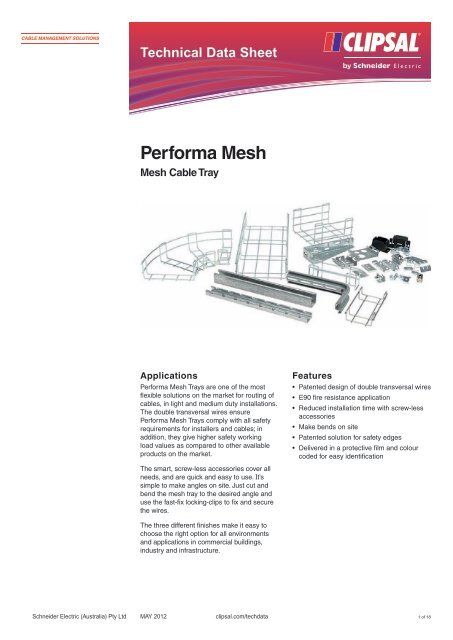
Product Data Sheet - Performa Mesh, Mesh Cable Tray ... - Clipsal
Product Data Sheet - Performa Mesh, Mesh Cable Tray ... - Clipsal
Product Data Sheet - Performa Mesh, Mesh Cable Tray ... - Clipsal

You also want an ePaper? Increase the reach of your titles
YUMPU automatically turns print PDFs into web optimized ePapers that Google loves.
Technical <strong>Data</strong> <strong>Sheet</strong><br />
<strong>Performa</strong> <strong>Mesh</strong><br />
<strong>Mesh</strong> <strong>Cable</strong> <strong>Tray</strong><br />
Applications<br />
<strong>Performa</strong> <strong>Mesh</strong> <strong>Tray</strong>s are one of the most<br />
flexible solutions on the market for routing of<br />
cables, in light and medium duty installations.<br />
The double transversal wires ensure<br />
<strong>Performa</strong> <strong>Mesh</strong> <strong>Tray</strong>s comply with all safety<br />
requirements for installers and cables; in<br />
addition, they give higher safety working<br />
load values as compared to other available<br />
products on the market.<br />
The smart, screw-less accessories cover all<br />
needs, and are quick and easy to use. It’s<br />
simple to make angles on site. Just cut and<br />
bend the mesh tray to the desired angle and<br />
use the fast-fix locking-clips to fix and secure<br />
the wires.<br />
The three different finishes make it easy to<br />
choose the right option for all environments<br />
and applications in commercial buildings,<br />
industry and infrastructure.<br />
Schneider Electric (Australia) Pty Ltd MAY 2012<br />
clipsal.com/techdata<br />
Features<br />
• Patented design of double transversal wires<br />
• E90 fire resistance application<br />
• Reduced installation time with screw-less<br />
accessories<br />
• Make bends on site<br />
• Patented solution for safety edges<br />
• Delivered in a protective film and colour<br />
coded for easy identification<br />
1 of 18
Specifications<br />
Technical and material data<br />
Steel wire Specification C4D: EN 10016-2-3<br />
C7D: EN 10016-2-3<br />
AISI 304 (Stainless steel): EN 10088-2<br />
Density 7.85kg/m³<br />
Surface treatment Electro-zinc (>8µm): EN 12329-1<br />
Hot-dip galvanised (>70 µm): ENISO 1461<br />
(Stainless steel)<br />
Steel sheet Specification Dx51D+Z275 MA-C<br />
Dx51D+ZM175 MA-C<br />
Density 7.85kg/m³<br />
Surface treatment Electro-zinc (>8µm): EN 12329-1<br />
Hot-dip galvanised (>70µm): ENISO 1461<br />
(Stainless steel)<br />
Resistance to impact IK-10 (EN 50102)<br />
Temperature range From –40°C to +120°C<br />
Fire resistance E90 classified (DIN 4102-12)<br />
Standards The products comply with the standards:<br />
• IEC 61537<br />
– Loading and deflection<br />
– Electrical continuity across couplers<br />
– System with electrical continuity<br />
• IEC 60068-2-75 (resistance to impact)<br />
• EN ISO 9227 (salt spray test)<br />
Dimensions<br />
Detailed dimensions<br />
<strong>Mesh</strong> tray size Longitudinal Transversal<br />
Height x width (mm) Length (mm) wire Ø (mm) wire Ø (mm)<br />
35 x 100<br />
3000<br />
4.4<br />
3.9<br />
35 x 150<br />
3000<br />
4.4<br />
3.9<br />
35 x 200<br />
3000<br />
4.4<br />
3.9<br />
35 x 300<br />
3000<br />
4.4<br />
3.9<br />
60 x 60 3000 4.4 3.9<br />
70 x 100<br />
3000<br />
4.4<br />
3.9<br />
70 x 150<br />
3000<br />
4.4<br />
3.9<br />
70 x 200<br />
3000<br />
4.9<br />
3.9<br />
70 x 300(*)<br />
3000<br />
4.9<br />
3.9<br />
70 x 400(*)<br />
3000<br />
4.9<br />
3.9<br />
70 x 500(*)<br />
3000<br />
4.9<br />
3.9<br />
70 x 600(*)<br />
3000<br />
4.9<br />
3.9<br />
105 x 200(*)<br />
3000<br />
4.9<br />
3.9<br />
105 x 300(*)<br />
3000<br />
4.9<br />
3.9<br />
105 x 400(*)<br />
3000<br />
4.9<br />
3.9<br />
105 x 500(*)<br />
3000<br />
4.9<br />
3.9<br />
105 x 600(*)<br />
Note:<br />
3000<br />
4.9<br />
3.9<br />
(*) The longitudinal wire Ø for the stainless steel range is 4.4mm.<br />
Schneider Electric (Australia) Pty Ltd clipsal.com/techdata 2 of 18
<strong>Cable</strong> capacity<br />
<strong>Mesh</strong> tray size Height (mm) Width (mm) Cross section (mm²)<br />
35 x 100<br />
35 x 150<br />
35 x 200<br />
35 x 300<br />
35<br />
35<br />
35<br />
35<br />
Schneider Electric (Australia) Pty Ltd clipsal.com/techdata 3 of 18<br />
100<br />
150<br />
200<br />
300<br />
2688<br />
4288<br />
5888<br />
9088<br />
60 x 60 60 60 2666<br />
70 x 100<br />
70 x 150<br />
70 x 200<br />
70 x 300(*)<br />
70 x 400(*)<br />
70 x 500(*)<br />
70 x 600(*)<br />
105 x 200(*)<br />
105 x 300(*)<br />
105 x 400(*)<br />
105 x 500(*)<br />
105 x 600(*)<br />
70<br />
70<br />
70<br />
70<br />
70<br />
70<br />
70<br />
105<br />
105<br />
105<br />
105<br />
105<br />
100<br />
150<br />
200<br />
300<br />
400<br />
500<br />
600<br />
200<br />
300<br />
400<br />
500<br />
600<br />
5268<br />
9112<br />
12,328<br />
19,028<br />
25,728<br />
32,428<br />
39,128<br />
18,768<br />
28,968<br />
39,168<br />
49,368<br />
59,568<br />
Note:<br />
* Unless it is stated in the country’s regulations, we suggest the following orientative values to determine the<br />
cable tray to be installed:<br />
• Fill factor value to be applied to the cross-sectional area of the cables: 80% for power cables and 40% for<br />
data cables<br />
• Enlargement factor: 30%.
Typical Installation<br />
Overall View Ceiling Suspended Solutions<br />
Components<br />
1. Ceiling bracket omega 10. Fast-fix suspended bracket<br />
2. Vertical/suspended/floor bracket 11. Support for box/bracket<br />
3. Beam clamp 12. Fast-fix hanger 35<br />
4. Profile fast-fixing + profile 21 x 41/41 x 41 13. Central suspension support<br />
5. Pendant bracket 14. ID label<br />
6. Swivel support + U-profile 15. C-shape support<br />
7. Extendable joint 16. Take-off plate<br />
8. Cover fixing 17. Earthing clamp<br />
9. Cover 18. L-shape support.<br />
EZ: Electro zinc – indoor installations, not aggressive atmosphere (office building and commercial<br />
shopping centres).<br />
HDG: Hot-dip galvanisation – indoor installations, aggressive atmosphere, tunnels, underground,<br />
outdoor installations and urban locations.<br />
SS: Stainless steel – chemical industries, acid and alkaline atmosphere, food industry,<br />
atmospheres with halogen. Other possible applications may include harbours, marinas and water<br />
treatment facilities.<br />
LZ: Lamellar zinc is a zinc and aluminium coating with a degree of resistance to severe<br />
atmospheres, comparable to that of hot-dip galvanised steel. It is used for small items, to achieve<br />
a smooth surface.<br />
BC: Bi-chromate (according to 12329-1) is a process that deposits a thin layer of zinc over the<br />
steel through an electro-chemical process, with an additional passivation that gives a typical yellow<br />
colour. The benefits of this process are control over zinc thickness and smoother surfaces.<br />
Schneider Electric (Australia) Pty Ltd clipsal.com/techdata 4 of 18
Overall View Wall and Floor-Mounted Solutions<br />
Components<br />
1. <strong>Mesh</strong> tray 11. Fast-fix horizontal bracket<br />
2. Horizontal bracket set 12. <strong>Cable</strong> drop-out<br />
3. Pendant bracket + U-profile 13. Fast-fix divider<br />
4. Horizontal bracket omega 14. Vertical/suspended/floor bracket<br />
5. Coupler 15. ID label<br />
6. Side coupler 16. Support for box + bracket<br />
7. Fast coupler 70 + 105 17. Insulating floor support<br />
8. Locking clip for flat bends 18. Vertical/suspended/floor bracket<br />
9. Horizontal bracket 19. Adjustable bracket set.<br />
10. Spring nut + profile 2121/4141<br />
EZ: Electro zinc – indoor installations, not aggressive atmosphere (office building and commercial<br />
shopping centres).<br />
HDG: Hot dip galvanisation – indoor installations, aggressive atmosphere, tunnels, underground,<br />
outdoor installations and urban locations.<br />
SS: Stainless steel – chemical industries, acid and alkaline atmosphere, food industry,<br />
atmospheres with halogen. Other possible applications may include harbours, marinas and water<br />
treatment facilities.<br />
LZ: Lamellar zinc is a zinc and aluminium coating with a degree of resistance to severe<br />
atmospheres, comparable to that of hot dip galvanised steel. It is used for small items, to achieve<br />
a smooth surface.<br />
BC: Bi-chromate (according to 12329-1) is a process that deposits a thin layer of zinc over the<br />
steel through an electro-chemical process, with an additional passivation that gives a typical<br />
yellow colour. The benefits of this process are control over zinc thickness and smoother surfaces.<br />
Schneider Electric (Australia) Pty Ltd clipsal.com/techdata 5 of 18
Cat.<br />
Number<br />
Description<br />
<strong>Mesh</strong> <strong>Tray</strong>s Electro-Zinc<br />
4511110 <strong>Mesh</strong> <strong>Tray</strong> 35 x 100 EZ<br />
4511115 <strong>Mesh</strong> <strong>Tray</strong> 35 x 150 EZ<br />
4511120 <strong>Mesh</strong> <strong>Tray</strong> 35 x 200 EZ<br />
4511130 <strong>Mesh</strong> <strong>Tray</strong> 35 x 300 EZ<br />
<strong>Mesh</strong> <strong>Tray</strong>s Hot-Dip Galvanised<br />
4512110 <strong>Mesh</strong> <strong>Tray</strong> 35 x 100 HDG<br />
4512115 <strong>Mesh</strong> <strong>Tray</strong> 35 x 150 HDG<br />
4512120 <strong>Mesh</strong> <strong>Tray</strong> 35 x 200 HDG<br />
4512130 <strong>Mesh</strong> <strong>Tray</strong> 35 x 300 HDG<br />
<strong>Mesh</strong> <strong>Tray</strong>s Stainless Steel<br />
4515110 <strong>Mesh</strong> <strong>Tray</strong> 35 x 100 SS<br />
4515115 <strong>Mesh</strong> <strong>Tray</strong> 35 x 150 SS<br />
4515120 <strong>Mesh</strong> <strong>Tray</strong> 35 x 200 SS<br />
4515130 <strong>Mesh</strong> <strong>Tray</strong> 35 x 300 SS<br />
Cat.<br />
Number<br />
Description<br />
<strong>Mesh</strong> <strong>Tray</strong>s Electro-Zinc<br />
4511230 <strong>Mesh</strong> <strong>Tray</strong> 70 x 300 EZ<br />
4511240 <strong>Mesh</strong> <strong>Tray</strong> 70 x 400 EZ<br />
4511250 <strong>Mesh</strong> <strong>Tray</strong> 70 x 500 EZ<br />
4511260 <strong>Mesh</strong> <strong>Tray</strong> 70 x 600 EZ<br />
<strong>Mesh</strong> <strong>Tray</strong>s Hot-Dip Galvanised<br />
4512230 <strong>Mesh</strong> <strong>Tray</strong> 70 x 300 HDG<br />
4512240 <strong>Mesh</strong> <strong>Tray</strong> 70 x 400 HDG<br />
4512250 <strong>Mesh</strong> <strong>Tray</strong> 70 x 500 HDG<br />
4512260 <strong>Mesh</strong> <strong>Tray</strong> 70 x 600 HDG<br />
<strong>Mesh</strong> <strong>Tray</strong>s Stainless Steel<br />
4515230 <strong>Mesh</strong> <strong>Tray</strong> 70 x 300 SS<br />
4515240 <strong>Mesh</strong> <strong>Tray</strong> 70 x 400 SS<br />
4515250 <strong>Mesh</strong> <strong>Tray</strong> 70 x 500 SS<br />
4515260 <strong>Mesh</strong> <strong>Tray</strong> 70 x 600 SS<br />
Parts List and Safe Working Loads<br />
The safe working load is calculated according to the Standard IEC 61537. See diagrams below.<br />
• The load is uniformly distributed along the mesh trays.<br />
• The maximum distance between couplers and brackets is 1/5 of the span between brackets.<br />
• The safety working load value is given when:<br />
• the longitudinal deflection is
Cat.<br />
Number<br />
Description<br />
<strong>Mesh</strong> <strong>Tray</strong>s Electro-Zinc<br />
4511206 <strong>Mesh</strong> <strong>Tray</strong> 60 x 60 EZ<br />
4511210 <strong>Mesh</strong> <strong>Tray</strong> 70 x 100 EZ<br />
4511215 <strong>Mesh</strong> <strong>Tray</strong> 70 x 150 EZ<br />
4511220 <strong>Mesh</strong> <strong>Tray</strong> 70 x 200 EZ<br />
<strong>Mesh</strong> <strong>Tray</strong>s Hot-Dip Galvanised<br />
4512206 <strong>Mesh</strong> <strong>Tray</strong> 60 x 60 HDG<br />
4512210 <strong>Mesh</strong> <strong>Tray</strong> 70 x 100 HDG<br />
4512215 <strong>Mesh</strong> <strong>Tray</strong> 70 x 150 HDG<br />
4512220 <strong>Mesh</strong> <strong>Tray</strong> 70 x 200 HDG<br />
<strong>Mesh</strong> <strong>Tray</strong>s Stainless Steel<br />
4515206 <strong>Mesh</strong> <strong>Tray</strong> 60 x 60 SS<br />
4515210 <strong>Mesh</strong> <strong>Tray</strong> 70 x 100 SS<br />
4515215 <strong>Mesh</strong> <strong>Tray</strong> 70 x 150 SS<br />
4515220 <strong>Mesh</strong> <strong>Tray</strong> 70 x 200 SS<br />
Cat.<br />
Number<br />
Description<br />
<strong>Mesh</strong> <strong>Tray</strong>s Electro-Zinc<br />
4511320 <strong>Mesh</strong> <strong>Tray</strong> 105 x 200 EZ<br />
4511330 <strong>Mesh</strong> <strong>Tray</strong> 105 x 300 EZ<br />
4511340 <strong>Mesh</strong> <strong>Tray</strong> 105 x 400 EZ<br />
4511350 <strong>Mesh</strong> <strong>Tray</strong> 105 x 500 EZ<br />
4511360 <strong>Mesh</strong> <strong>Tray</strong> 105 x 600 EZ<br />
<strong>Mesh</strong> <strong>Tray</strong>s Hot-Dip Galvanised<br />
4512320 <strong>Mesh</strong> <strong>Tray</strong> 105 x 200 HDG<br />
4512330 <strong>Mesh</strong> <strong>Tray</strong> 105 x 300 HDG<br />
4512340 <strong>Mesh</strong> <strong>Tray</strong> 105 x 400 HDG<br />
4512350 <strong>Mesh</strong> <strong>Tray</strong> 105 x 500 HDG<br />
4512360 <strong>Mesh</strong> <strong>Tray</strong> 105 x 600 HDG<br />
<strong>Mesh</strong> <strong>Tray</strong>s Stainless Steel<br />
4515320 <strong>Mesh</strong> <strong>Tray</strong> 105 x 200 SS<br />
4515330 <strong>Mesh</strong> <strong>Tray</strong> 105 x 300 SS<br />
4515340 <strong>Mesh</strong> <strong>Tray</strong> 105 x 400 SS<br />
4515350 <strong>Mesh</strong> <strong>Tray</strong> 105 x 500 SS<br />
4515360 <strong>Mesh</strong> <strong>Tray</strong> 105 x 600 SS<br />
Load Kg/m<br />
Load Kg/m<br />
110<br />
100<br />
90<br />
80<br />
70<br />
60<br />
50<br />
40<br />
30<br />
20<br />
10<br />
200<br />
185<br />
170<br />
155<br />
140<br />
125<br />
110<br />
95<br />
80<br />
65<br />
50<br />
0<br />
1m<br />
1m<br />
Schneider Electric (Australia) Pty Ltd clipsal.com/techdata 7 of 18<br />
1.25m<br />
1.25m<br />
1.50m<br />
Span<br />
1.50m<br />
Span<br />
1.75m<br />
1.75m<br />
2m<br />
2m
Admissible working-load on brackets<br />
The safe working-load is calculated according to the standard IEC 61537.<br />
See diagrams below:<br />
• The load is uniformly distributed along the bracket<br />
• The safety working-load value is given when the deflection is ≤5% of the width of the bracket.<br />
Horizontal wall solutions<br />
Cat. No. Load kg* Cat. No. Load kg*<br />
Horizontal bracket 45xx110 324 Fast-fix horizontal 45xx110 324<br />
45xx115 306<br />
bracket<br />
45xx115 306<br />
45xx120 273 45xx120 273<br />
45xx130 214 45xx130 214<br />
45xx140 191 45xx140 191<br />
45xx150 178 45xx150 178<br />
45xx160 154 45xx160 154<br />
Horizontal bracket set 45xx210 418 Horizontal bracket 45xx310 198<br />
45xx215 428<br />
omega<br />
45xx315 121<br />
45xx220 345 45xx320 100<br />
45xx230 331 45xx330 78<br />
45xx240 315<br />
45xx250 250<br />
45xx260 190<br />
Ceiling-suspended solutions<br />
Suspended bracket 45xx310 51 Reinforced<br />
45xx620 505<br />
45xx315 52<br />
suspended bracket<br />
45xx630 481<br />
45xx320 59 45xx640 515<br />
45xx330 62 45xx650 442<br />
45xx340 56 45xx660 460<br />
45xx350 42<br />
45xx360 35<br />
Horizontal bracket 45xx410 264 Swivel support + 45xx410 + 90<br />
omega<br />
45xx415<br />
45xx420<br />
154<br />
107<br />
U-profile<br />
+ pendant bracket<br />
45xx420 +<br />
45xx910<br />
45xx430 85 45xx410 +<br />
45xx420 +<br />
45xx915<br />
85<br />
45xx410 +<br />
45xx420 +<br />
45xx920<br />
45xx410 +<br />
45xx420 +<br />
45xx930<br />
45xx410 +<br />
45xx420 +<br />
45xx940<br />
45xx410 +<br />
45xx420 +<br />
45xx950<br />
45xx410 +<br />
45xx420 +<br />
45xx960<br />
Schneider Electric (Australia) Pty Ltd clipsal.com/techdata 8 of 18<br />
80<br />
70<br />
60<br />
50<br />
40
Admissible working load on brackets (continued).<br />
Ceiling-suspended solutions<br />
Ref. No. Load kg* Load kg*<br />
double¹)<br />
Fast-fix suspended 45xx510 127 –<br />
bracket<br />
45xx520 138 –<br />
45xx530 98 –<br />
45xx540 70 250<br />
45xx550 60 230<br />
45xx560 49 170<br />
45xx570 – 140<br />
45xx580 – 140²)<br />
45xx590 – 140²)<br />
Note:<br />
¹ ) Two brackets back-to-back, fixed together with bolts.<br />
² ) Per metre, with a maximum distance between two threaded rods of 950mm. The<br />
threaded rods must be placed all along the bracket.<br />
* These values refer to all the surface treatments available for each bracket.<br />
XX in ref no. refers to finish (EZ or HDG)<br />
i.e. 45xx110 - xx (for full cat. number please refer to TPG).<br />
Resistance to traction<br />
1 U-profile +<br />
1 pendant<br />
bracket<br />
1 L-shape<br />
support<br />
1 C-shape<br />
support<br />
1 Threaded<br />
rod M6-M8<br />
Resistance to<br />
traction (kg)<br />
1000<br />
362<br />
400<br />
100<br />
According to the standard IEC 61537<br />
1: Measuring point for the deformation<br />
F: Strength<br />
Schneider Electric (Australia) Pty Ltd clipsal.com/techdata 9 of 18<br />
1<br />
F
Recommended couplers<br />
<strong>Mesh</strong> tray<br />
size<br />
Options for side-coupling<br />
(the quantity equals the sum of both sides)<br />
Side couplers Couplers Fast couplers<br />
Couplers used as<br />
central couplers<br />
35 x 100<br />
Not required<br />
35 x 150<br />
35 x 200<br />
2 2 2<br />
1<br />
1<br />
35 x 300 2<br />
60 x 60 2 2 2 Not required<br />
70 x 100<br />
Not required<br />
70 x 150 2 2 2<br />
1<br />
70 x 200 1<br />
70 x 300<br />
2<br />
70 x 400<br />
70 x 500<br />
2 4 2<br />
2<br />
3<br />
70 x 600 3<br />
105 x 200<br />
1<br />
105 x 300 2<br />
105 x 400 2 4 4<br />
2<br />
105 x 500 3<br />
105 x 600 3<br />
Recommended fixings for brackets<br />
Width of mesh tray<br />
(mm)<br />
No. of fixings for all kinds of<br />
brackets<br />
60 1 Profile fast-fixings, fixings<br />
100 1<br />
150 2<br />
200 2<br />
300 3<br />
400 4<br />
500 4<br />
600 4<br />
Schneider Electric (Australia) Pty Ltd clipsal.com/techdata 10 of 18
Available<br />
Surface treatments for all environments<br />
EZ = Electro-zinc<br />
HDG = Hot-dip galvanised<br />
SS = Stainless steel<br />
Accessories also available<br />
PG = Pre-galvanised<br />
LZ = Lamellar zinc<br />
BC = Bi-chromate<br />
Indoor installations, unaggressive atmosphere (office building,<br />
commercial malls)<br />
Indoor installations, aggressive atmosphere, tunnels,<br />
underground<br />
Outdoor installation, urban location<br />
Chemical industries, acid and alkaline atmosphere<br />
Harbours, marinas and water treatment<br />
Food industry<br />
Atmosphere with halogen<br />
Electrozinc<br />
EZ<br />
Hot-dip<br />
galvanised<br />
HDG<br />
Recommended<br />
Stainless<br />
steel<br />
SS<br />
EZ: Electro-zinc (according to EN 12329-1) is a process that deposits a thin layer of zinc over the<br />
steel through an electro-chemical process, with an additional passivation that gives a typical shiny<br />
grey colour. The benefits of this process are control over zinc thickness and smoother surfaces.<br />
HDG: Hot-dip galvanisation (EN ISO 1461) is the process of coating steel with a zinc layer, by<br />
passing the steel through a molten bath of zinc at a temperature of more than 400 °C. The result is a<br />
surface treatment that protects the steel from environmental elements.<br />
SS: Stainless steel AISI 304 (EN 10088-2) offers a high resistance to aggressive atmospheres. The<br />
pickling and passivation processes taking place after manufacturing improve the degree of protection<br />
of the steel.<br />
PG: Pre-galvanised steel (EN 10346) is carbon steel that has gone through a zinc bath just after<br />
rolling. Good protection against oxidation and rust.<br />
LZ: Lamellar zinc is a zinc and aluminium coating with a degree of resistance to severe atmosphere<br />
comparable to that of hot dip galvanised steel. It is used for small items to achieve a smooth surface.<br />
BC: Bi-chromate (according to 12329-1) is a process that deposits a thin layer of zinc over the steel<br />
through an electro-chemical process, with an additional passivation that gives a typical yellow colour.<br />
The benefits of this process are control over zinc thickness and smoother surfaces.<br />
Schneider Electric (Australia) Pty Ltd clipsal.com/techdata 11 of 18
Instructions for Making Accessories<br />
The <strong>Performa</strong> <strong>Mesh</strong> <strong>Tray</strong>s are delivered with a protective transparent plastic film. Forget about dust<br />
and humidity! Each mesh tray also has a colour code for easy identification of the surface treatment.<br />
How to cut the mesh trays Coupling of all elements<br />
L<br />
470<br />
B<br />
130<br />
MÁX 3 mm<br />
MÁX 3 mm<br />
Kg<br />
2,7<br />
Fast-fixing of large radius flat bends<br />
L<br />
B<br />
Part number<br />
45 xx 900<br />
L<br />
Height<br />
(mm)<br />
18 21<br />
Schneider Electric (Australia) Pty Ltd clipsal.com/techdata 12 of 18<br />
B<br />
Width<br />
(mm)<br />
B<br />
L<br />
Part number<br />
45 xx 110<br />
L<br />
Height<br />
(mm)<br />
B<br />
Width<br />
(mm)<br />
23.5 23.5<br />
Torque<br />
12<br />
Value of recommended torque.
How to cut to obtain different kind of angles<br />
C 1<br />
W<br />
mm<br />
C 3<br />
W<br />
mm<br />
C 5<br />
W<br />
mm<br />
60 100 150 200 300 400 500 600<br />
o o o o o o o o<br />
20 13 10 7 5 4 3 2<br />
Approximate angles.<br />
60 100 150 200 300 400 500 600<br />
o o o o o o o o<br />
125 85 55 37 25 19 15,5 12<br />
Approximate angles.<br />
60 100 150 200 300 400 500 600<br />
o o o o o o o o<br />
180 135 90 67 45 34 27 22<br />
Approximate angles.<br />
60 100 150 200 300 400 500 600<br />
o o o o o o o o<br />
145 100 65 44 30 23 18,5 C14 5<br />
Practical application of the various cuts.<br />
How to obtain the same angle with different bending<br />
radii function of numbers of cuts.<br />
Example:<br />
For a mesh tray width of W = 300, to realise<br />
an angle of 60°.<br />
OPTION 1: 3 cuts (20° + 20° + 20°)<br />
OPTION 2: 2 cuts (30° + 30°)<br />
These examples can apply for any width of mesh trays.<br />
Schneider Electric (Australia) Pty Ltd clipsal.com/techdata 13 of 18<br />
C 2<br />
W<br />
mm<br />
C 4<br />
W<br />
mm<br />
60 100 150 200 300 400 500 600<br />
o o o o o o o o<br />
90 64 45 30 20 15 12.5 10<br />
Approximate angles.<br />
Approximate angles.<br />
W (mm)<br />
Corte 60 100 150 200 300 400 500 600<br />
C1 20° 13° 10° 7° 5° 4° 3° 2°<br />
C2 90° 64° 45° 30° 20° 15° 12.5° 10°<br />
C3 125° 85° 55° 37° 25° 19° 15.5° 12°<br />
C4 145° 100° 65° 44° 30° 23° 18.5° 14°<br />
C5 180° 135° 90° 67° 45° 34° 27° 22°<br />
W<br />
mm<br />
60 100<br />
o o<br />
180 135
Large radius flat bends<br />
L<br />
C 2<br />
WW<br />
60 100 150 200 300 400 500 600<br />
C1<br />
C2<br />
C3<br />
r<br />
x4<br />
255<br />
x2<br />
+<br />
x1<br />
200<br />
x2<br />
50<br />
x3<br />
75<br />
x2<br />
+<br />
x2<br />
110<br />
x6<br />
175<br />
x8<br />
225<br />
x9<br />
260<br />
L 450 450 210 310 550 600 760 900<br />
780 780 335 480 930 930 1225 1370<br />
Necessary<br />
length<br />
C 1<br />
mm<br />
L<br />
r o<br />
90<br />
Coupling of large radius bends<br />
L<br />
B<br />
Part number<br />
45 xx 900<br />
L<br />
Height<br />
(mm)<br />
Schneider Electric (Australia) Pty Ltd clipsal.com/techdata 14 of 18<br />
C 2<br />
B<br />
Width<br />
(mm)<br />
18 21<br />
C 1<br />
C 2<br />
C 3<br />
W<br />
W = 100 mm<br />
W<br />
W = 300 mm<br />
C 3<br />
C 2<br />
C 2<br />
C 3<br />
C 3<br />
C 1<br />
C 2<br />
C 3<br />
C 2<br />
C 2<br />
C 3<br />
C 1
Right-angle flat bends<br />
W<br />
mm<br />
60 100 150 200 300 400 500 600<br />
(approx.)<br />
Coupling of right angle flat bends<br />
B<br />
L<br />
Part number<br />
45 xx 110<br />
ALLOW<br />
MOUNTING LIDS<br />
L<br />
Height<br />
(mm)<br />
B<br />
Width<br />
(mm)<br />
23.5 23.5<br />
ALLOW<br />
MOUNTING LIDS<br />
Schneider Electric (Australia) Pty Ltd clipsal.com/techdata 15 of 18<br />
Torque<br />
12<br />
Value of recommended torque<br />
W<br />
mm<br />
2<br />
3<br />
60 100 150 200 300 400 500 600<br />
1<br />
L<br />
(approx.)<br />
L
T-junction (90˚ radius)<br />
ALLOW<br />
MOUNTING LIDS<br />
1<br />
2<br />
60 100 150 200 300 400 500 600<br />
Cut matches with transversal mesh<br />
(approx.)<br />
L<br />
Coupling of T-junction (90˚ radius)<br />
B<br />
L<br />
Part number<br />
45 xx 110<br />
L<br />
Height<br />
W<br />
B<br />
Width<br />
23,5 23,5<br />
Schneider Electric (Australia) Pty Ltd clipsal.com/techdata 16 of 18<br />
Torque<br />
12<br />
Value of recommended torque<br />
2<br />
5<br />
1<br />
3<br />
L= W<br />
L<br />
4<br />
W
Reducer<br />
W<br />
mm<br />
1<br />
2<br />
3<br />
60 100 150 200 300 400 500 600<br />
L= W-W 1<br />
L W 1<br />
Coupling of reducers<br />
B<br />
L<br />
W<br />
Part number<br />
45 xx 110<br />
ALLOW<br />
MOUNTING LIDS<br />
(approx.)<br />
L<br />
Height<br />
(mm)<br />
B<br />
Width<br />
(mm)<br />
23.5 23.5<br />
ALLOW<br />
MOUNTING LIDS<br />
Schneider Electric (Australia) Pty Ltd clipsal.com/techdata 17 of 18<br />
Torque<br />
12<br />
Value of recommended torque.
Raisers:<br />
Schneider Electric (Australia) Pty Ltd<br />
33-37 Port Wakefield Road,<br />
Gepps Cross, South Australia 5094<br />
Contact us clipsal.com/feedback<br />
National Customer Care Enquiries:<br />
1300 2025 25<br />
V1.1<br />
C n1<br />
C n2<br />
C n3<br />
Angles according to flat<br />
convex<br />
concave concave convex<br />
35<br />
de 0 a 180º<br />
From 0 to 180º<br />
de 0 a 155º<br />
From 0 to 155º<br />
45º<br />
45º<br />
45º<br />
45º<br />
60/70<br />
de 0 a 180º<br />
From 0 to 180º<br />
de 0 a 90º<br />
From 0 to 90º<br />
25º<br />
25º<br />
25º<br />
25º<br />
105<br />
de 0 a 180º<br />
From 0 to 180º<br />
de 0 a 60º<br />
From 0 to 60º<br />
15º<br />
15º<br />
15º<br />
15º<br />
Coupling of raisers:<br />
B<br />
L<br />
Part number<br />
45 xx 110<br />
L<br />
Height<br />
(mm)<br />
B<br />
Width<br />
(mm)<br />
23.5 23.5<br />
Torque<br />
12<br />
C n3<br />
C n1<br />
35<br />
60/70<br />
105<br />
Value of recommended torque.<br />
CONCAVE CONVEX<br />
CONVEX<br />
CONCAVE<br />
convex concave<br />
r<br />
65 185 315 450<br />
25<br />
0<br />
-<br />
x1 x2 x3 x4 x1<br />
r<br />
125 220 300<br />
90 180 250<br />
50 150 250<br />
x2 x3 x4<br />
18 of 18<br />
Radius according to flat<br />
convex<br />
o<br />
90<br />
concave<br />
C n1<br />
r<br />
o<br />
90<br />
r<br />
Schneider Electric (Australia) Pty Ltd reserves the right to change specifications, modify designs<br />
and discontinue items without incurring obligation and whilst every effort is made to ensure that<br />
descriptions, specifications and other information in this document are correct, no warranty is<br />
given in respect thereof and the company shall not be liable for any error therein.<br />
© 2012 Schneider Electric. All Rights Reserved.<br />
Trademarks are owned by Schneider Electric Industries SAS or its affiliated companies.<br />
CLIPCOM24642 April 2012