One of my bucket list items since I read my first party report back in 1991 was to attend a european demoparty and compete in a compo. I competed at NAID ’96 and placed there, which was awesome, but to compete with the best of the best, and win, has always been a dream of mine. I’m happy to announce that after six months of hard work with good friends and extremely talented people, we achieved just that. Our demo, 8088 MPH, won the Revision 2015 oldskool demo compo. (A personal victory for me was having it shown last in the compo, which is a sign of respect that the organizers think it’s the best high to end a compo in.) As of April 7th 2015, there are no IBM PC emulators in the world that can run the demo properly; they hang or crash before the demo is finished, and the colors are wrong. Same goes for anything that isn’t the target hardware (see below). To see what 8088 MPH looks like, I direct you to the video+audio capture of the demo running on real hardware: Because there are so many technological world-firsts in the demo, and because we’re bending the hardware in ways that people have never thought to do so, it’s only fair that we try to explain exactly how this was achieved. One of my roles was “organizer” for the demo, so I’ll break it down scene by scene, covering the basics of each trick. For parts that I wrote, I go into some detail, but for a deep technical dive into certain areas, I’ll keep this blog entry updated to point to reenigne’s, VileR’s, and Scali’s blog posts about their parts. It is our hope that these discussions will foster revived “old-school” interest in software development for the platform. After you read this summary post, please visit the following links by us that break down, in-depth, specific sections of the demo:
- 1K colours on CGA: How it’s done
- 8088 PC Speaker MOD player: How it’s done
- More 8088 MPH how it’s done
- 8088 MPH: How it came about
- CGA in 1024 Colors – a New Mode: the Illustrated Guide
- Sprites? Where we’re going, we don’t need… sprites!
- 8088 MPH: The polygons
And for more general info:
- reenigne’s blog (specific 8088 MPH posts forthcoming, but check out previous material to get more 8088+CGA technical goodness)
- Using Photoshop as a CGA Bitmap Paint Program
- Scali’s Openblog (retroprogramming category)
Target Hardware Specifications
Before going into each part, let’s define what the target system was for the demo: A 1981 IBM 5150 (aka the very first “IBM PC”) with 640 KB RAM, a floppy drive, IBM CGA card, and internal speaker. That setup consists of:
- 4.77 MHz 8088 CPU. 5 MHz seems like a lot compared to other 8-bit micros, but it takes the CPU 4 cycles to read a single byte. So, compared to other 8-bit CPUs like the 6502 or 6809, which can read a byte in one clock cycle, the effective clock speed of the 8088 is more like (4.77 / 4) = 1.19 MHz.
- Video adapter that has a 9-pin RGBI interface and an RCA NTSC composite video interface. Driven by a Motorola 6845 character generator. No facilities for changing text characters; font is fixed.
- Internal speaker; no sound card like the Sound Blaster, or special sound hardware like the C64 SID. Speaker can be driven by a timer pin to produce a square wave, or can be bit-banged directly via a port or a one-shot timer.
The 640KB RAM requirement seems steep, but not only was it possible to add that to the first IBM PCs, by 1985 it was quite common. If you still want to cry foul, then please note the only effect that uses just about all of that RAM is the kefrens bars, so that the repeating pattern would take longer to repeat and be more pleasing to the eye. We could have reduced it, but then you might have noticed the pattern repeating quicker. With the kefrens bars effect, the demo uses 507 KB RAM; without it, the demo uses 349 KB. Most effects use much less, and some are tiny, like the plasma which uses only 6KB (which includes the banner graphics) and the picture of the girl which uses 18K (2K more than the size of the raw picture data itself). We intentionally traded size for speed, which was a deliberate decision to fit as many effects as we could into 8 minutes running time, the compo limit. If we had a few more minutes running time, we probably could have fit the entire demo into 256 KB or even less, but you would have waited longer between effects. I should also note here that there were two different versions of IBM CGA produced, which differ mainly in how composite colors are generated. We had equal numbers of both “old” and “new” style IBM CGA cards, so we chose to compose graphics for the “old” style. If you have the “new” style CGA card, the demo will still run, but the colors will be off slightly.
Technical Breakdown
Development tools used
- Turbo C
- Turbo Pascal
- Turbo Assembler
- Turbo Debugger
- Visual C++
- OpenWatcom
- NASM (and YASM)
- DOSBox
- A few real IBM 5160s (hardware equivalent to the 5150, but easier to find in the real world)
Any data files were directly included in the .exe/.com files themselves. This kept everything together in the same binary which means the data could benefit from compression (see below). Most development cycles involved designing in wetware, coding on a modern system (or DOSBox running on a modern system), testing/debugging in DOSBox, and then transferring over to real hardware for a final test. Once an effect grew so sophisticated it couldn’t run in an emulator any more, this cycle slowed down as testing could only be done on real hardware. Various transfer methods were used to get code to real hardware: Scali used a serial cable; I used an ethernet card running a packet driver and mTCP; at the party we used an 8-bit IDE ISA adapter (Silicon Valley ADP-50) connected to a CF-to-IDE adapter to make a CF card the hard drive, then used a USB CF card reader to move stuff back and forth. The most intriguing method of all was reenigne’s method, who used a custom controller connected to the keyboard port that used the IBM BIOS factory test mode as a poor-man’s serial port. (I hope Andrew writes up some details on that!)
Loader, API, and general structure
We all had different preferred development languages and environments, so it was decided early on to create an overseeing “loader” that would execute .EXE and .COM files, and then people could develop effects in whatever environment they wanted to. This is not a new concept; the famous Second Reality demo did this for exactly the same reasons, and the same technique was used even earlier than that on numerous demos on other platforms. (Before you ask: No, the Second Reality code was not copied; in fact, it wasn’t even consulted, as we had to write extremely tight code to minimize memory usage, and also have it work on an 8088 (the Second Reality code uses 80186 opcodes). The loader API services assemble to about 450 bytes of code. The loader, as designed, would be responsible for:
- Playing music in the background
- Masking the load times and precalc times of various effects using “megademo”-style text
- Providing synchronization services (such as providing a vertical-retrace interrupt in software, and a user-definable countdown timer)
Running effects with the loader consisted of this workflow:
- Print text on the screen and animate it using an interrupt and the 6845 start address register
- Execute the effect
- The effect would decompress, perform precalc, etc. and then signal the loader it is ready to start
- The loader cleans up the moving onscreen text, then signal the effect it can start
- Effect starts, magic occurs
Designing this correctly was extremely important, as any bugs would derail the entire thing. It was designed fully before even a single line of code was written. I’ve shared the design doc online for the curious. (I wrote the loader.) The background music playback had to be as simple as possible so as to not interfere with any effects. A single PC beep, changing (or silencing) once every frame, was the only thing that was practical, so 60Hz beeping is what the background music consists of. The composition program used for generating the speaker timer values was MONOTONE. Even though the code for playback is only 18 lines of assembler, it takes up two scanlines onscreen, so you can see how anything even slightly more complicated would have sucked much more CPU out of the system and some of the full-screen 60Hz effects simply would not have been possible.
Executable compression
Another decision early on was to see if executable compression was feasible, which means the following:
- Does it actually compress things small enough to be worthwhile?
- Is the decompression quick enough to avoid long pauses in the demo?
- Does the decompression routine affect the system while it decompresses? (ie. does it disable interrupts or something else equally horrible while it decompresses, which would trash the demo?)
I gathered most classic and modern executable compressors and ran tests against old programs that were representative of what we would be producing. The results were welcome surprises. The compression ratios were good enough that we could afford to include precalc’d data instead of calculating it on the fly, and the decompression was fast enough that the total end-to-end time loading a program from diskette was actually slightly faster than if it were to load uncompressed. In the end, pklite emerged as the winner. I’ve shared the comparison data online for comparison. (If I missed any packers that hold substantial advantages over the ones in the data, please let me know what they are. There were nearly 100 packers made for DOS, but unless they compress smaller than apack or upx, or decompress faster than pklite or lzexe — all while remaining compatible with 8088 — then I don’t want to hear about them.)
Scene-by-scene breakdown
What follows is a screen-by-screen explanation of each effect. As previously stated, I’ll only describe scenes in detail if I wrote them; it will be up to the others if they want to write a technical breakdown for their parts. The explanation for each effect follows after the effect’s screenshot.  The introduction was meant to serve two purposes: To educate the audience on the system and explain at just how much of a disadvantage we were trying to make a world-class demo on such hardware, and also simultaneously shatter their expectations :-) The text mode is obviously simulated; I essentially duplicated the basic BIOS functions for handling text mode but simulated in graphics mode. The cursor blinking and text blinking are handled identically to how the 6845 does it, adding to the illusion. It is (nearly) impossible to change the display start address of graphics mode such that every single scanline comes from a different place, so the title screen unrolling was done brute force, by copying new scanlines into memory hidden by retrace. The title screen goes away with a “fade” on the top edge by ANDing a mask on successive lines of the screen data.
 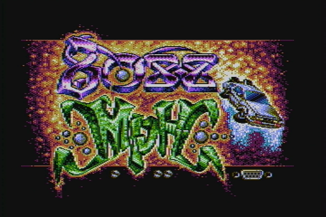 A lot of people think the title screen is the same picture demonstrated by VileR a few years ago. It’s not! He recomposed it for 16-color composite specifically for this demo, and changed it subtlety as well.
  The bobbing was achieved by creating a software vertical retrace interrupt that fired at the same place onscreen every time (just after the last displayed line) and then hooking it with a 6845 display start address change routine. Flags were used to communicate to the interrupt if it was time to erase the letters, which was done by simply using REP STOSW to fill screen memory with black lines. Because the 6845 displays two onscreen rows per “row”, the text could only move to even lines, which is why the movement isn’t as smooth as it could be. Well, to be fair, it could be made to move to any line we wanted, but doing so would be CPU intensive, and the whole point of the loader is to use as little CPU as possible, so this was the compromise. The simulated vertical retrace interrupt was provided through loader API services for the rest of the effects to use as well. Effects could disable it, re-initialize it, and hook/unhook their own routines to it.
 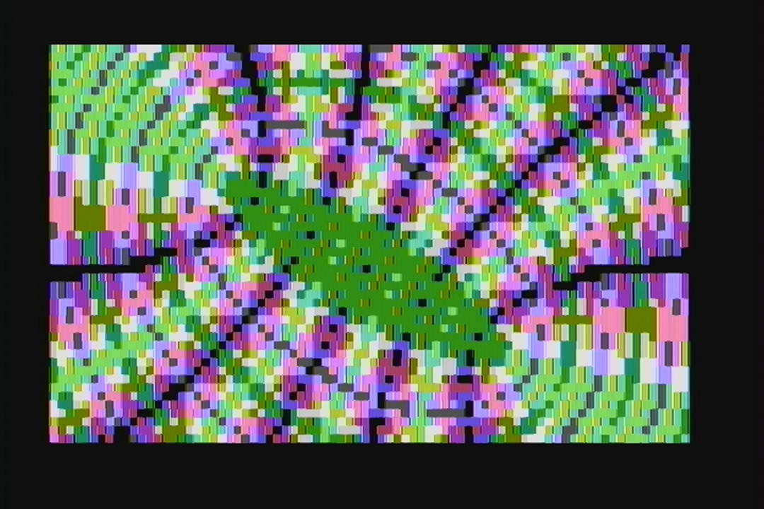 The moire (interference pattern) effect was achieved using a base of 40×25 text mode, the half-char block extended ASCII characters, and lots of unrolled code. The circles were chosen to represent the classic effect, but in reality the effect can combine any two images. reenigne’s effect.
  The rotozoomer is the same tired old routine I first rolled out in 1996 in the 8086 compo, but optimized to the hilt and sped up by only drawing every other line. A miscommunication between me and VileR resulted in probably not the best texture to demonstrate the effect, but it still runs well enough. There were plans to include a 60 Hz version of this effect, but we ran out of time.
 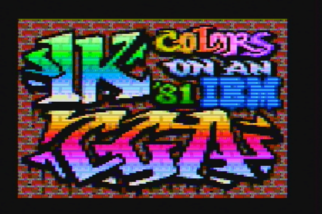 The core concept of the 1024-color mode is a serious abuse of 80×25 text mode with the NTSC colorburst turned on. VileR made the first discovery with 512 colors, and reenigne was able to double this to 1024 with CRTC trickery. Some people thought the entire demo was in this mode. It was not, because 80-column text mode suffers from the famous CGA “snow” defect when you write directly to CGA RAM in this mode. This is unfortunately visible in the plasma effect (see below). BTW, when I saw this picture in 2013, that’s when I knew I had to get all these people together to make a demo. I mean, geezus, look at it! My jaw dropped when I saw it. Had I never seen VileR’s collaboration with reenigne to make the above, 8088 MPH might never have existed.
  These stars were actually the result of unrolled code and a precalc’d table that, together, take a byte from one location and moves it to another position in video RAM. While we had other patterns ready, such as a swirling display, we felt the starfield was most appropriate for a typical “oldskool” demo. reenigne’s effect.
  The sprite part seems like black magic, but is the combination of using a sprite compiler written by Scali, and adjusting the screen vertically using the 6845 start address register. CGA only has one screen’s worth of video memory, so moving the address down scrolls the screen up, with the data repeating across the boundary. The data doesn’t repeat evenly across the boundary, however, requiring handling. The timer was monitored to know when the screen line containing the last pixel of the sprite had been drawn, which prompted redrawing the sprite. (In other words, re-drawing the sprite was an exercise in racing the beam.) Timing was very tight to avoid screen/sprite tearing effects.
  Also part of the compiled sprite effect, this displays 30 vectorballs at 30 Hz. We had an earlier display that used less balls to achieve 60 Hz, but Scali had the idea at the last minute to make them spell out something like “8088”, “IBM”, etc. and coded up the change at the party. The update is done using double-buffering; the sprites only take up a small rectangular area onscreen, so the screen mode’s CRTC settings were reprogrammed to provide a video mode with a small area in the middle of the physical screen, using only half of available video memory. This provided a true hidden page to draw/erase vectorballs to, which was then flipped to be visible using the 6845 display start address register.
 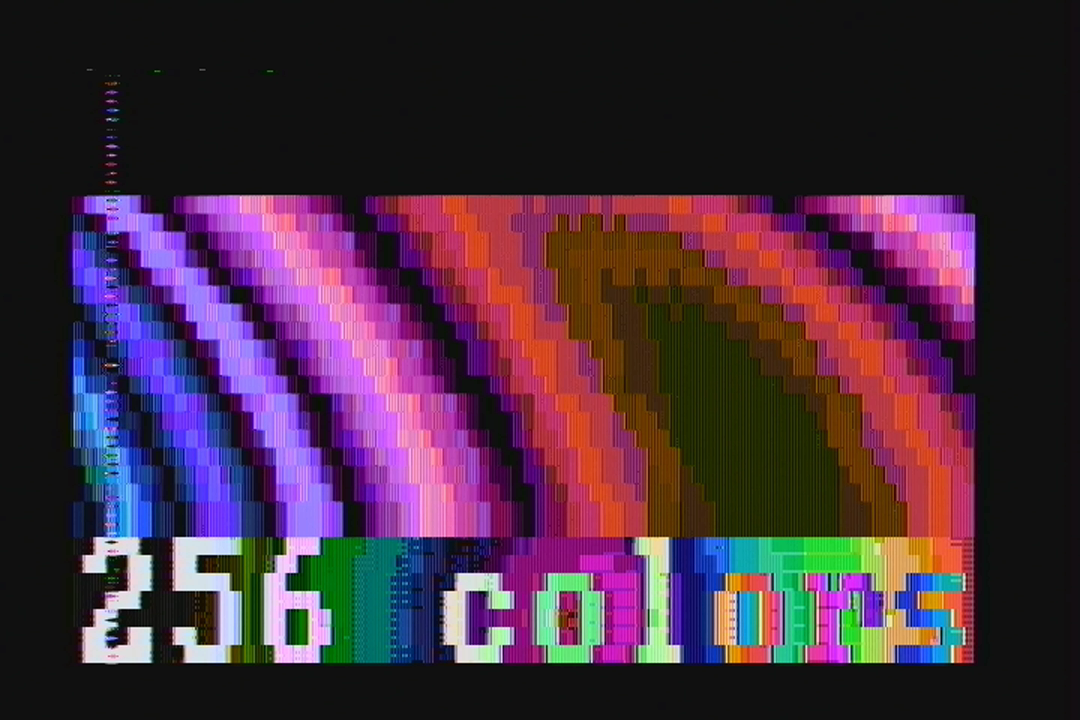 Using a 1024-color variant screen mode that could be updated using only the attribute byte (thereby limiting the number of colors to 256), this plasma had to perform writes only when the CRT beam was retracing horizontally or vertically. Unfortunately, the timing required to get this right stopped working at the party for some reason (probably happened as we were rearranging effect order), and as a result you can see a line of noise along the left side of the screen, and a little bit of noise at the top. This was my fault, as I wrote the effect using a somewhat lazy polling routine. It’s a shame CGA snow exists, because without all the retrace handling to avoid it, this effect runs at 60fps. In the demo with snow avoidance, it runs at only 20fps. VileR may write more about how this screen mode and color system is constructed, and if so, I’ll update the links at the top of this article to point to the method. If we come out with a final version of the demo, fixing this is at the top of the priority list. In fact, I’m betting reenigne could change this from a polling effect to a cycle-counting effect, which would not only fix the snow, but speed it up.
 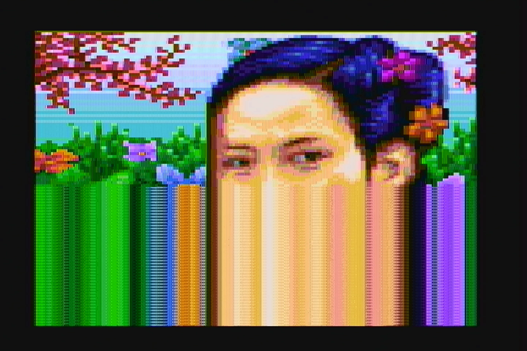 The 1024-color mode reprograms the start address every two lines. I took advantage of this behavior to create a simple “drip” effect for VileR’s amazing artwork. Already you can posit that much more complicated effects are possible (thinking of the Copper demo here) but I ran out of time to make it more awesome.
  This classic Kefrens bars effect was done by reenigne in 320x200x4 mode. It’s a cycle-counting effect, as there is simply no time to monitor for horizontal retrace. To ensure the cycle counting was consistent, several things were done including changing the system default DRAM refresh from it’s default interval of 18 to 19, to get the DRAM refresh periods to line up with CRTC accesses.
  This was Scali’s effect and inspired by his 1991 demo which also featured a large torus. There are several things going on here:
- Only changed portions of the screen are calculated and drawn, to minimize the amount of bandwidth needed to update the screen (this is the same “delta drawing” idea used in XDC). This was done because CGA video memory has a wait state, so the less you need to write to it, the better.
- 320x200x4 mode is used with a background and palette combination that gives this specific composite color palette, which included many shades of blue.
- To help with the shading, dithering is applied during rasterization.
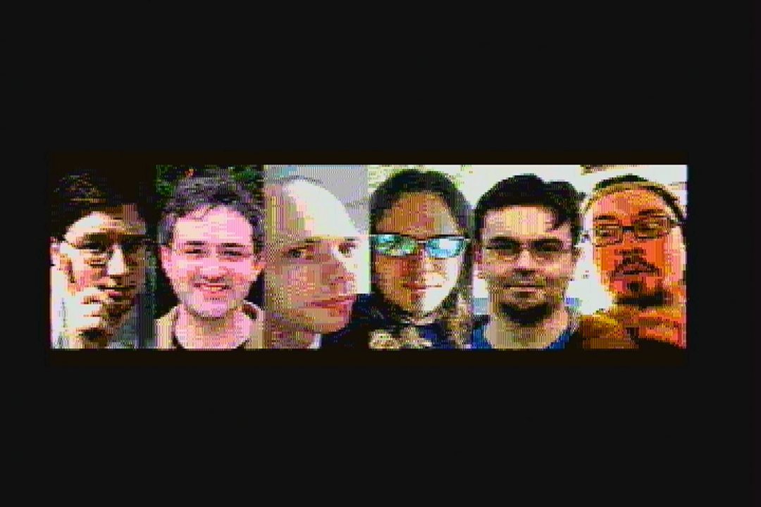 At the party, reenigne posited that it should be possible to restart the CRTC start address every single scanline. This would result in a video mode that was only 100 lines high, and would give a 80×100 resolution 1024-color mode. The above is the result of that coding, plus really extensive work done on a CGA NTSC composite signal modeling program done by reenigne months earlier to perform the image conversion. (No, you can’t have it. And before you ask, the “girl” and “CGA 1k” pictures were not stock conversions, but were hand-pixeled by VileR in Photoshop, and the 4-colors/16-colors/”Until Now” screens in a customized version of Pablodraw he created.) We didn’t have time to put text into this picture, so the people you see above are the same as in credits order: Trixter, reenigne, Scali, VileR, Phoenix, and virt. Apologies to coda and puppeh, but as you can see, any more squishing and the faces would have been unrecognizable. Sorry!
  Finally, the coup de grâce: A multichannel music engine for the PC speaker. We didn’t want to just copy a ZX Spectrum engine, nor other engines such as the one used in Music Construction Set, but rather set the bar impossibly high by playing a protracker mod through the speaker. Other modplayers for the speaker already exist, but they require a 10 MHz 80286, and can barely manage output at a 6KHz sampling rate. Ours faithfully reproduces all protracker effects, mixing and outputting to the speaker realtime at 16.5 KHz, all on a 4.77 MHz CPU. This was reenigne’s baby, and is a truly stunning technical achievement that required unconventional thinking and considerable 8088 knowledge to pull off. I’m sure he will write up a more detailed post on how it was done. Until then, I can mention the following details:
- Preconversion of the module was necessary to align data structures and sample data to be favorable to how the 8088 indexes memory. Sample data is also converted.
- Each sample must take exactly 288 cycles to calculate and output or else the sound goes completely pants. This was very difficult to achieve. 4.77 MHz / 288 = 16572 Hz sample output.
- Audio output was done using traditional Pulse-Width Modulation (PWM) techniques, such as the kind made popular by Access’s Realsound. PC speaker PWM is performed by tying the PC speaker input pin to the programmable interrupt timer’s (PIT) channel 2, then programming PIT 2 for byte value one-shot mode. Any value sent to PIT 2 with the system configured like this will set the speaker HIGH and start a count, and when the count expires (ie. the sent value is reached), the speaker goes LOW again. This results in an audible carrier wave “whine”, which was why the output needed to be fast (16.5 KHz) so that the carrier wave was above the range of human hearing.
Fun fact: After preconversion of the song and being turned into a self-playing .exe, the final result is smaller after compression than the size of the original source module.
Party Sprint
At the party, we came with something that was 90% finished. Prior to arriving at the party, we created what we thought was a decent entry, and created two “failsafe” videos, one that was a capture for the bigscreen and another that showed the demo running on real hardware as verification for the judges. We were worried that the hardware we were bringing would get damaged in transit, so this was a precaution so that we could enter something if that happened. Thankfully, reenigne’s and Scali’s IBM 5160s arrived unharmed (which was especially remarkable since reenigne had to bring his from the UK to Germany on a series of trains!). We also brought two CGA cards, and two capture devices, and three different methods of exchanging new software bits from our laptops to the old hardware. You can never be too prepared! Most of the coding time at the party was spent adding the kefrens and ending portrait picture, eliminating bugs from each part where possible, adding nice transitions where possible, shaving seconds off of each part to stay within the compo limit, and rearranging parts so that virt’s BTTF-inspired tune’s intro lined up with the sprite part. We spent pretty much all our time before the compo coding, eating, or visiting the bathroom, and only had time to socialize after that. While we came mostly prepared for something that was worthy of entering the compo, the time spent at the party was invaluable for turning a rough draft into something that could really compete for first place. Having all four of us at the same table meant we could collaborate instantly. So, lesson learned: There are rarely substitutes for working together in person! One of the biggest improvements of “party collaborating” was the decision to change the credits from a variable-speed, text-only scrolling to a more evenly-paced, ANSI-style scrolling, which I think was the best implementation change compared to the bits we brought from home. To help save time (and to ensure the video was converted well — sorry, but most people don’t know how to deal with interlaced video properly), I offered to provide Gasman with a 720@60p video. The NTSC output of CGA is slightly off; instead of 262.5 lines per field, it generates 262. This means it generates 59.92 fields (29.96 frames) per second instead of the NTSC broadcast standard of 59.94 (29.97 fps). This throws off most modern capture devices; Scali had access to a high-quality Blackmagic Intensity Shuttle, for example, but it couldn’t lock onto the signal. I knew from experience that some cheap video capture devices, such as the Terratec Grabby or the Dazzle DVC100, have extra tolerance built into them as they were designed to be used with VCR sources, so I bought a few and sent one to reenigne for testing. For the capture, we used a DVC100 with some slight proc amp adjustments so that the capture looked as close to the CRT monitor output as possible. To further ensure better video capturing, we used VirtualDub for the capture software, which has an option to dynamically resample the input audio source to fit the capture framerate you are aiming for in case it’s slightly off, and the software and hardware combination worked very well. For grabbing the audio, we initially tapped the speaker with alligator clips, but Scali brought his Sound Blaster which had a real PC speaker tap you could hook up with an internal cable, so we used that for the final capture.
Looking to the future
After watching the demo and reading the above, you may be wondering if there is actually room for improvement. Believe it or not, there is: Alternative methods of sound generation and additional cycle-exact trickery are definitely possible. We had more effects to put into the demo, but ran out of time: We ran out of development time, and we also ran out of execution time, as the Revision compo limit was 8 minutes or less. I’ve known everyone who has worked on the demo collectively over 60 years. It was an honor and a privilege to work with them all to produce this demo. Will we work together again? I’d say it’s definitely possible; the day after the compo, we threw around some ideas, such as making a game next instead of a demo. Me personally, I’m burnt out and will be spending the next few weeks playing some games I’ve always wanted to finish, and working on my health. I also have some other large projects I want to get kickstarted this summer, such as something the PC software preservation movement desperately needs, and an online sound card museum. But hey, who knows.
Blogosphere Coverage and Discussions
- Pouet download/info page and discussion
- JWZ’s blog
- Vintage Computer Forums discussion
- Hacker News discussion
- MAMEWorld Forums discussion
- reddit discussion (and another) (and another)
- CPCWiki discussion
- VOGONS discussion
- Featured on Hackaday
- 1-bit Music / BEEPER music forums
- byuu’s message board
- Metafilter discussion
- boingboing discussion
- comp.arch discussion
- Hacker News discussion about NTSC signal generation
- Vice’s Motherboard talks about the demo 2 years later


You must be logged in to post a comment.