Skip navigation

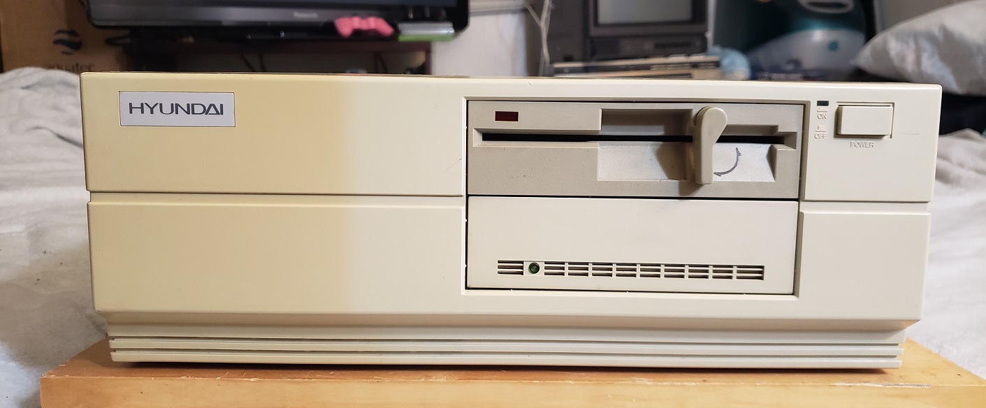
Today we will be taking a look at a pretty solid 286 PC from the late 1980s. The VTI Turbo 55 although not noticeable at first is actually a Samsung branded PC which becomes obvious if we take a look at the sticker on the back or at the motherboard itself. First though let’s take a look at the front of the case.

On the front we have a keyhole for locking the computer along with two LEDs for power and HDD activity. Below this is what looks like a third LED at first but its actually a slightly recessed reset button. It’s a double-edged sword though as the recessed button does make it almost impossible to accidentally reset the PC it also makes it a potential pain if you do want to use the button to reset as you’ll need a pen or otherwise small object to use to press the button. There is no power button on the Turbo 55 so turning the power on and off is performed via a switch on the power supply.

To the right of these LEDs and reset we have two 5 1/4 drive bays. Mine are occupied with a 1.2MB 5 1/2 floppy drive as well as a 1.44MB 3 1/2 floppy drive. As I have the original box with the original specs printed on it seems this PC came stock with only the 1.2MB 5 1/4 drive. The 1.44MB drive was a later addition from the previous owner. Two bays do not leave much room for expansion but for a 286 class PC you’re perfectly fine with a pair of floppy drives. If you really wanted to you could always track down a dual floppy drive and use the second bay for a CD-ROM drive or something along those lines.

The Turbo 55 is one of those PC’s that have the keyboard connector in the front which I’m not the biggest fan of though this is a largely personal preference

The keyboard itself is pretty well made and feels like a model M with nice clicky keys. There is also an XT-AT switch on the underside in case you wanted to use it with an even older PC in your collection.

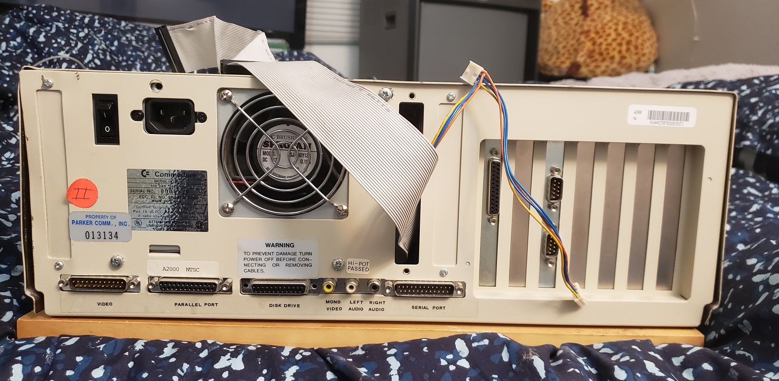
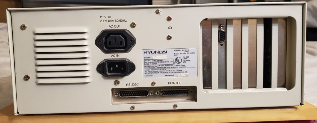
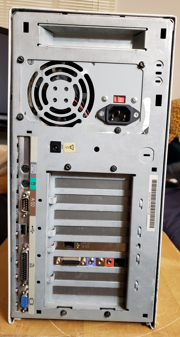
flipping the case around let’s take a look at the back.

You may notice the power supply looks well…incorrect. You would be right to think that and we will address that in a moment but first we will take a look at the built-in I/O ports. From left to right we have dual serial ports followed by a parallel port. Not a lot but as far as 286 PCs go it’s really nice to have anything built-in. Next to the parallel port we also have a curious switch with M below and C marked above. According to the documentation I could find on this model this is a monitor select switch with the M standing for mono and the C for color. The switch made no change as far as I could tell but I was using a later VGA card when I tested it so maybe it only works with CGA cards. To the right of this we have eight expansion slots with one being currently occupied by the EGA card.

Before opening the case and taking a look at the inside we can quickly talk about the power supply. The original power supply was a Han One HN-200c which when I received this computer was unfortunately completely dead.

In my foolishness though I ended up throwing it away since I just assumed it was a run of the mill AT power supply. In actuality the dimensions are a bit non-standard. The power supply I have installed currently is a newer ATX supply with an AT adaptor. It doesn’t fit quite fill the entire space so I just used some foam to fill the gap. Due to the lack of a power button I had to make sure the replacement PSU had a physical on/off switch.

The power connector on the motherboard itself is AT and any AT power supply (or adaptor) will connect to it just fine though the original HN-200C power supply did not have a split AT connector like most standard ones do.

With that out of the way lets take a look inside this PC.

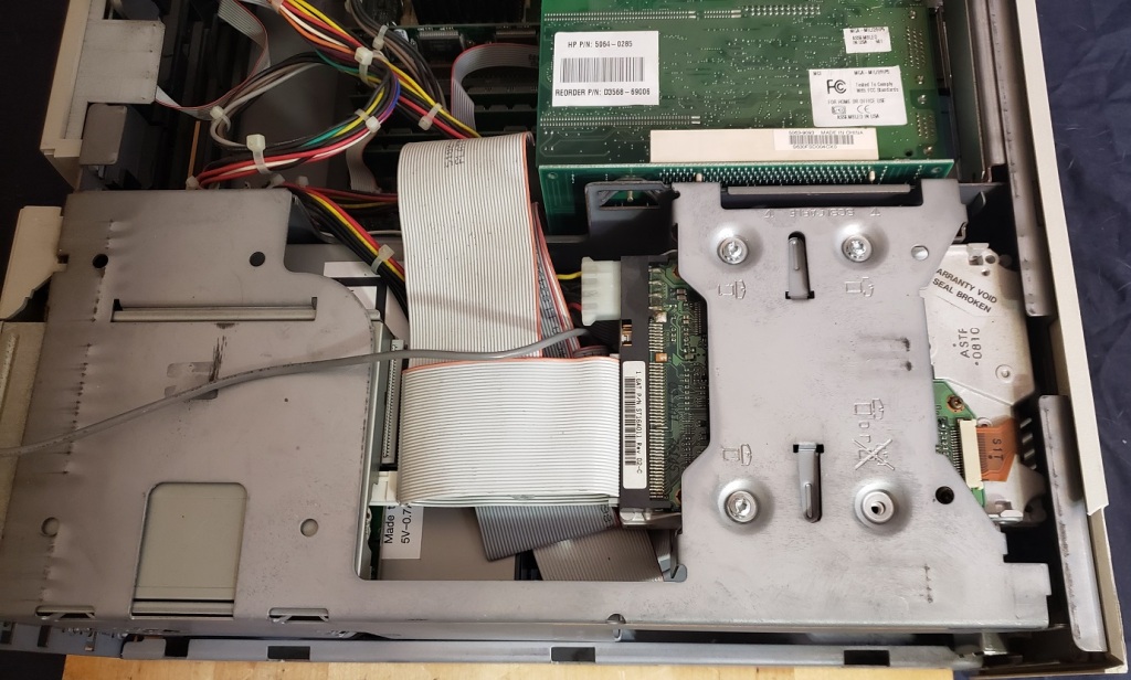
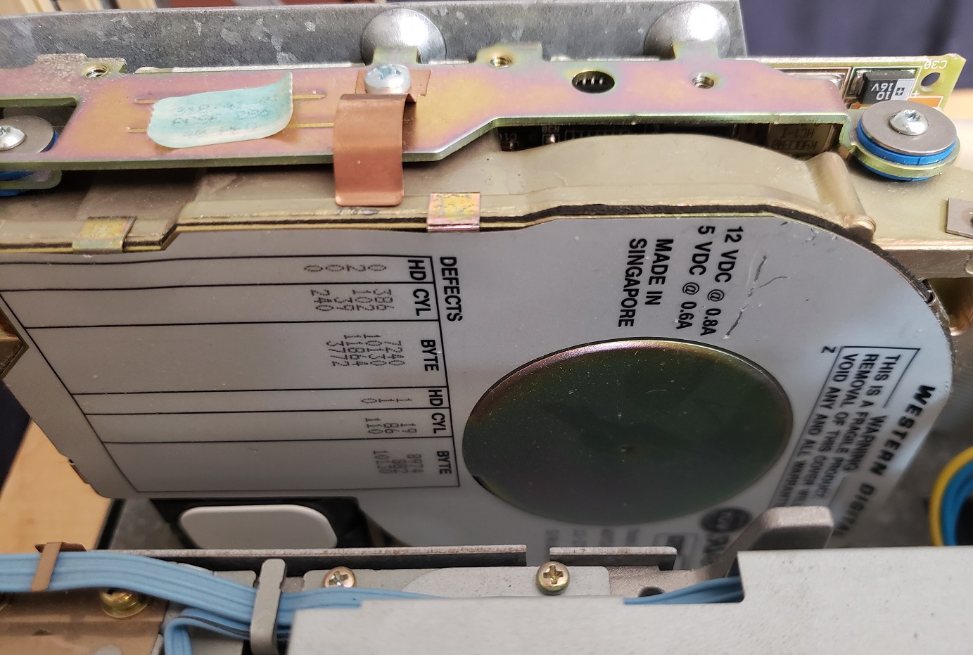
Before we take a look at the motherboard lets take a look at the two expansion cards that were installed when I originally acquired this PC. If you look at the image above you’ll notice the hard drive is mounted in a vertical orientation to the right of the floppy drives.

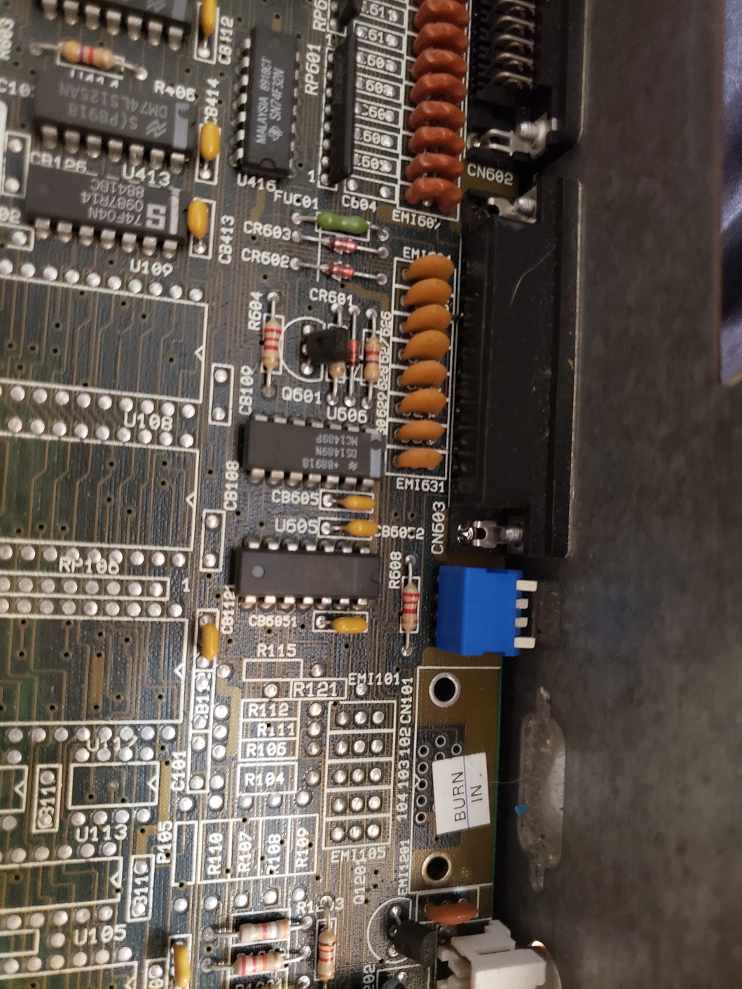
The hard drive is run off the 8-bit controller card above and is the uncommon XT-IDE or XTA interface. This is a seldom used interface only supported by a hand full of hard drives. The Commodore Colt I reviewed some time ago also used this interface for its hard drive. The hard drive attached is a Microscribe XTA hard drive of 40MB size. I do believe this controller card and hard drive are original to this PC. Unfortunately after several hours I could not get the VTI Turbo 55 to work with any 16-bit IDE controller or SCSI hard drive controller despite the PC having 16-bit ISA slots. Fortunately for me though the stock XTA controller and the hard drive still are functional.

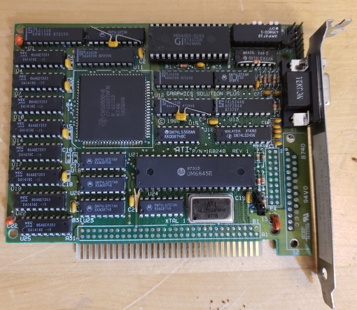
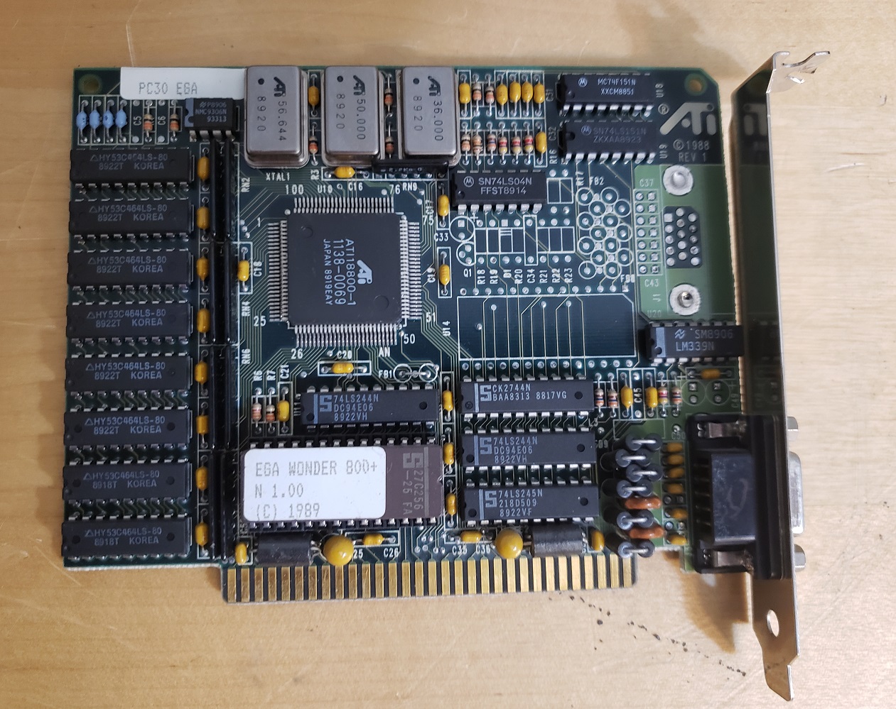
The only other expansion card installed was the video card.

The video card was an ATI EGA Wonder 800. I couldn’t find much information on this card but ATI was known to make some of the better cards of the time. The EGA 800 is also known to support extended EGA text and graphics modes as well as 16 color VGA modes. For convenience and due to my lack of a proper EGA monitor I replaced the card in my Turbo 55 with a slightly later 16-bit ATI VGA card.

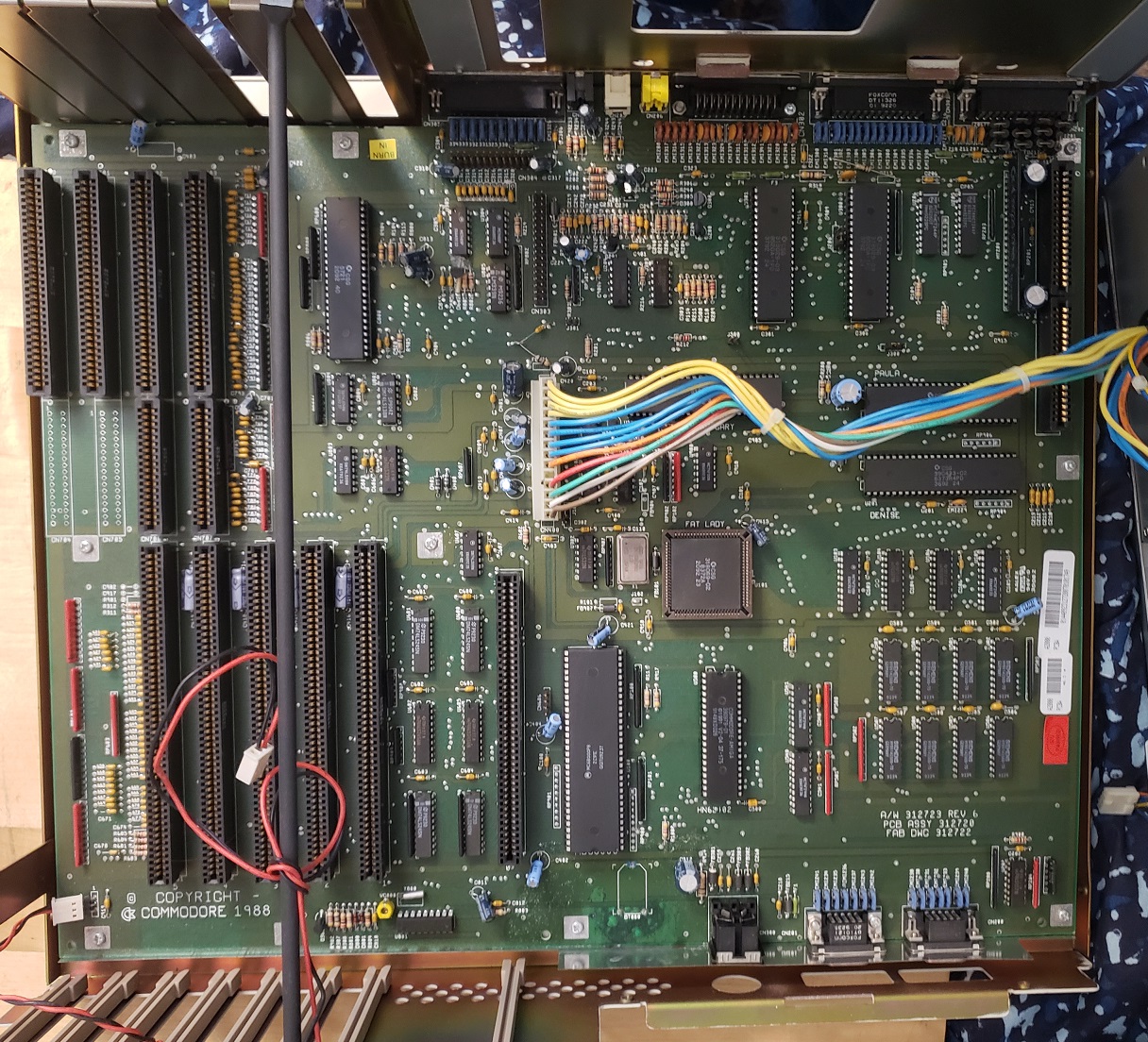
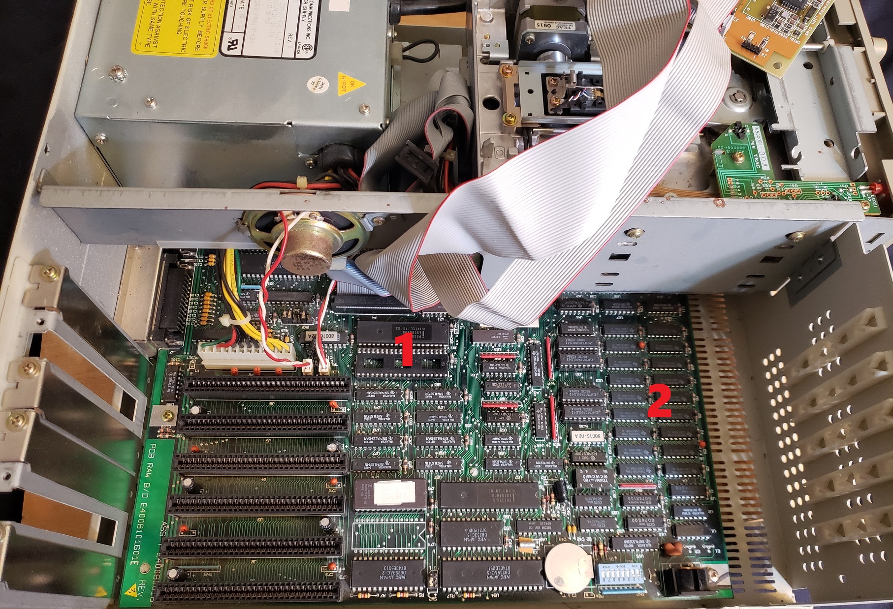
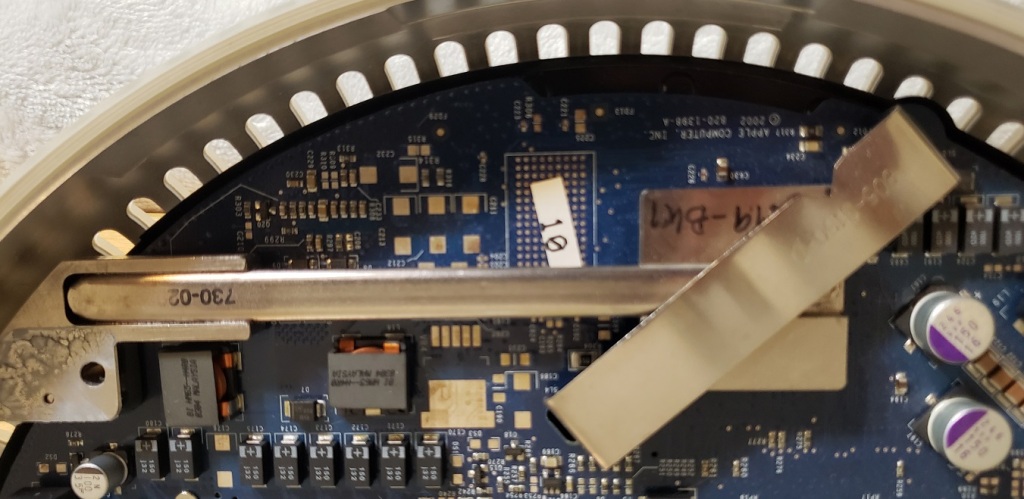
Now let’s take a look at the motherboard itself.

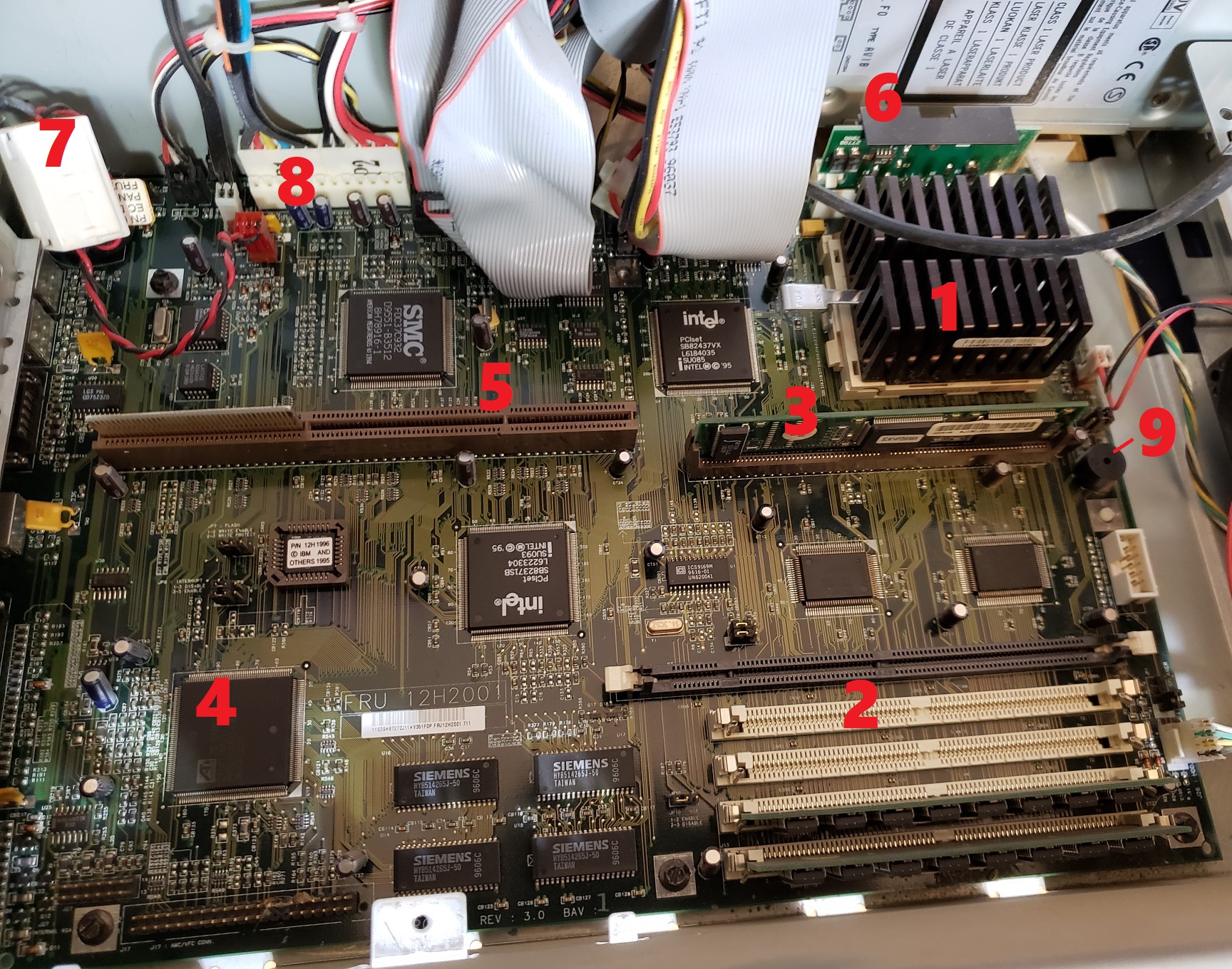
The motherboard seems to be a Samsung AT 286-12 AKA SD 550 with eight ISA slots, two 8-bit and six 16-bit.

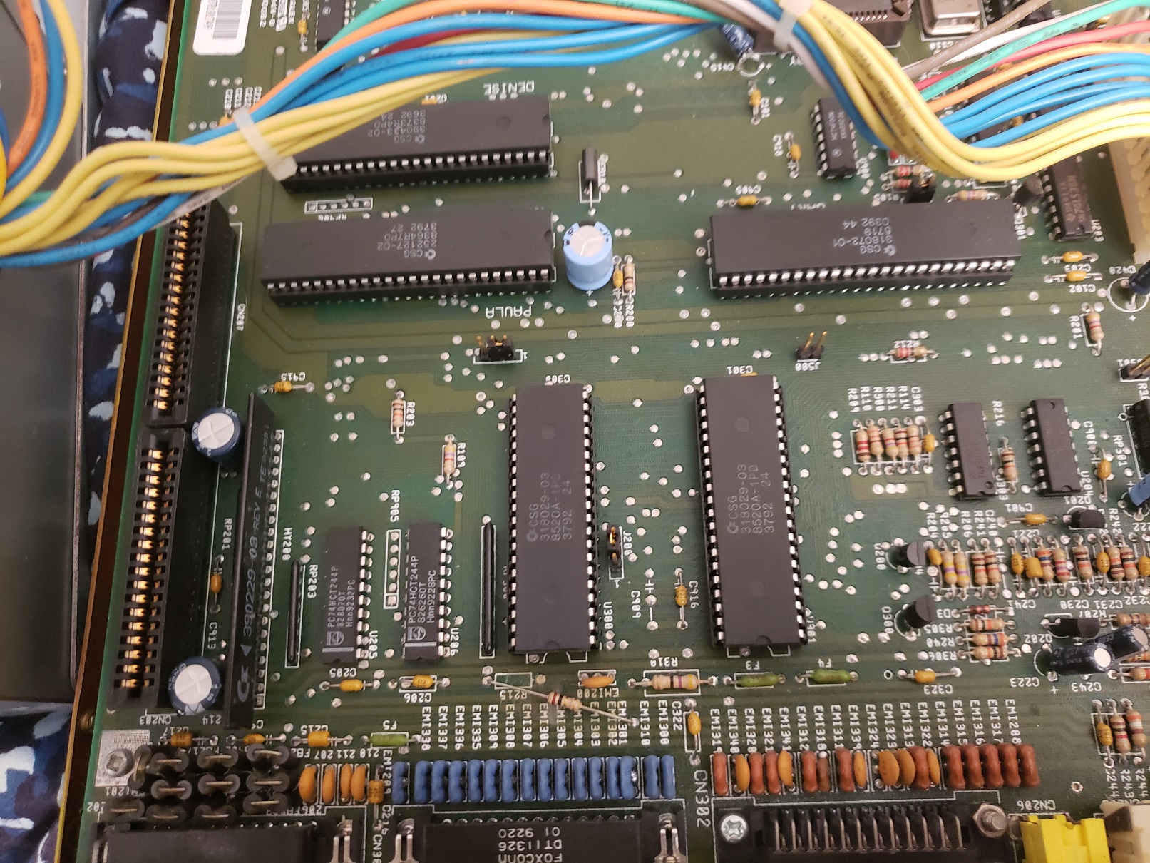
1 ) CPU – The CPU is an AMD branded 286-12 running at 12MHz. Interestingly this 286 is the N80L286-12 which is the lower powered variant running at 2.89W as opposed to 3.15 or 3.3W. the 286-12 was along with the 286-16 the quintessential and most common 286 CPU’s. Although fast enough to trigger issues with the more sensitive games meant for a slower 8088 when paired with decent VGA video card the 286-12 should have enough muscle to adequately run some slower paced VGA titles, specify point and click adventure titles.

2 ) FPU – As in most cases, my Turbo 55 came with an empty FPU socket and is a completely optional addition. For my Turbo 55 I chose to add a 287XL FPU. Unlike adding a standard 287-12 which would run at half the speed of the installed 286 (6MHz) the 287XL is actually a modified 387 FPU and should run at the full speed of the CPU which in this case is 12MHz. As I always feel obligated to mention the 287 regardless of its running speed will probably find very little use in this PC as very few games of the era took any advantage of a math co-processor chip. I did however find a CAD program installed on the hard drive which would be an application of the era that would have benefited from this upgrade.

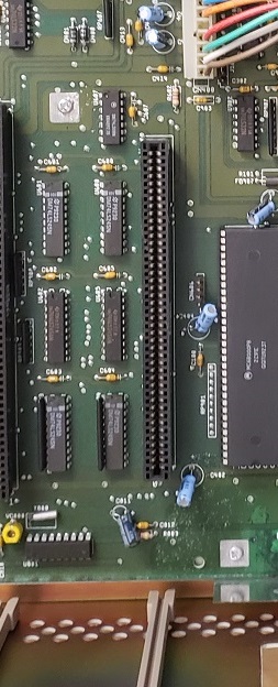
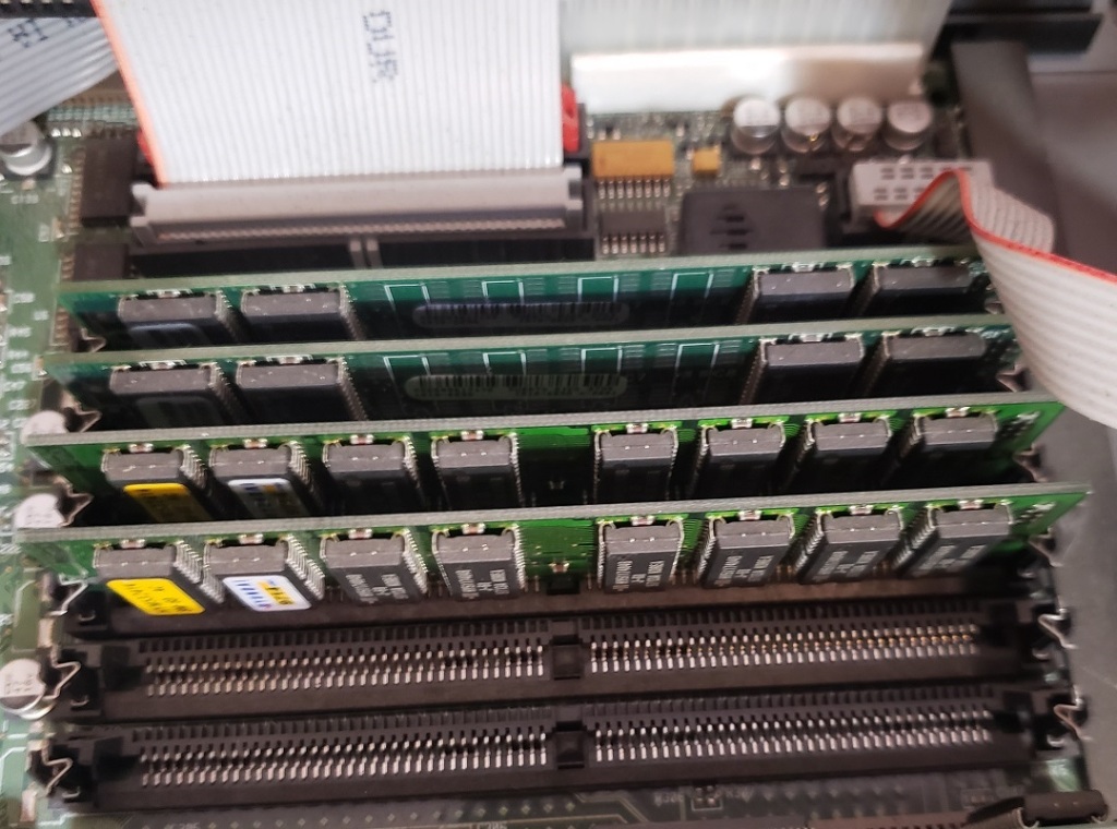
3 ) RAM – My Turbo 55 came with a full 1MB of memory on the motherboard though from what I can see on the box 640KB and 512KB options were available. 1MB would be more then enough for a 286 class PC such as the Turbo 55 and more RAM could always be added via ISA memory cards such as the Intel Above Board if so desired.

Half of the RAM chips on the motherboard are directly soldered on while the other half are socketed.

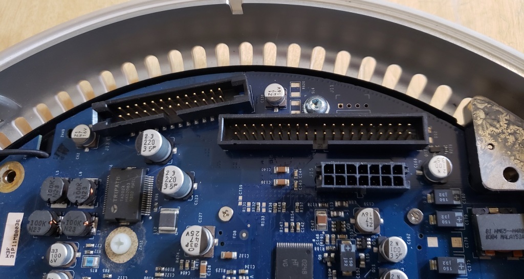
4) Floppy connector – The floppy controller is built-in and supports up to 1.2MB and 1.44 high density floppy drives.

5) Power connector – standard AT power connector.

The serial and parallel ports can be disabled via the jumpers 11 through 14 located above the RAM while wait states can be set from 1 to 0 via jumper 21 located under the 5 1/4 bays. When I set my wait states to 0 I noticed a significant speed increase but unfortunately this created many stability issues making the machine virtually unusable.

The VTI Turbo 55 is a capable 286. It can be argued that the 286 is a fairly useless CPU for modern retro PC enthusiasts as they are to fast for earlier games while for later titles a 386 can run everything a 286 can but vastly better. I personally still find a certain charm in running a 286 system and the Turbo 55 does in my opinion make a fine 286. The 12MHz speed gives you some wiggle room for playing games and with the right video card even lets you play some slower paced VGA titles just fine. 1MB of RAM is just about perfect for the time and considering the CPU you’ll likely not feel the need to play any games requiring more than the on board 1MB of memory. If you do there is always the option to add more memory via an expansion card.

Most of my negatives of the Turbo 55 are fairly minor such as the frontal keyboard connector or the unnecessarily, at least in my opinion, recessed reset button. The biggest issue I had with the Turbo 55 was the difficulty in adding a different type of hard drive controller. XTA is a very limiting hard drive interface considering it only works with a handful of now 25+ year old hard drives of limited capacity. I tried multiple 16-bit ISA IDE controllers and drives as well as multiple SCSI controllers and drives and found none to work. This does seem to be an issue common to some 286 class motherboards and unfortunately this seems to be one of them. I did not test a modern XT-IDE controller but hopefully maybe one of these would work as a hard drive replacement.

This slideshow requires JavaScript.

Previously we have looked at several black and white compact Macintosh computers including the Classic, Classic II and Macintosh SE. Today we are going to take a look at the pinnacle of the B/W compact Mac family, the Macintosh SE/30.

The Macintosh SE/30 was released in 1989 and was a compact mac to rule them all. It offered the power of its larger Macintosh II brothers in a small compact package as well as some future upgradability.

The front of the SE/30 is obviously dominated by its 9-inch 512×346 pixel black and white screen. The quality of this screen is excellent and games designed for the b/w mac look great on this machine. Other then the screen we have a small HDD activity LED hidden within the horizontal lines below the screen. The floppy drive is a 1.44MB drive which on the SE/30 for the first time came standard on a compact mac.

The only dial or button on the face of the SE/30 is a brightness dial for the monitor hidden away below the Apple badge and model name.

First off on the lower left side of the rear is the expansion card plate for certain expansion cards. This SE/30 previously seems to have had a Radius display card but unfortunately the card was removed by the previous owner but the bracket was left behind. To the right of this we have a standard 3-prong power connector and the power switch.

Taking a look at the various ports starting from the lower left we have dual ADB ports for keyboard and mouse. Next to this we have an external floppy drive connector for attaching well, an external floppy drive. Next is an external SCSI port for connecting external SCSI devices such as hard drives and CD-ROM drives. Next is an apple printer and then modem jack and lastly we have a 1/8 stereo audio out jack for connecting headphones or external speakers. Since we are talking about the sound the SE/30 uses an Apple Sound Chip (ASC) including four-voice, wavetable synthesis and stereo sampling generator. The sound coming from the built in internal speaker will be mono but anything through the rear audio jack, wether speakers or headphones will be stereo.

Removing the case reveals the drives and internals.

It is fairly cramped inside but the motherboard is fairly easy to remove as it just slides up and then away. Remember to detach the cables before removing the motherboard though.

The fan header, floppy and SCSI cable and power cable need to be unplugged from the motherboard. Only the power cable may present an issue since it can be a little stubborn and hard to reach. Below the CRT tube is a tray for an optional SCSI hard drive. Generally the SE/30 was sold with either a 40MB or 80MB hard drive installed but the system will take as large as a drive as you can find. I currently have a 300MB hard drive installed. Below the hard drive is a 1.44MB floppy drive.

Above is the motherboard for the SE/30 after being separated from the case. A common point of failure on these boards as with most of the older Macs are the silver surface mounted capacitors. These tend to leak over time but can be replaced with modern equivalents.

1 ) CPU – The CPU is the Motorola 68030 running at 16MHz. This is the same CPU and speed as some of the SE/30’s big brother full sized Macs such as the Macintosh IIx and IIcx. Due to the SE/30’s 32-bit bus it is the fastest of the black and white compact macs being even faster than the Mac classic II which features the same CPU and speed but only ran on a 16-bit bus.

2 ) FPU – One other feature of the SE/30 is the inclusion of an FPU co-processor standard on the motherboard as opposed to being optional. The Motorola 68882 FPU unit helped when performing more complex math functions though like the on the PC I’m not sure it was utilized very often in games. You could argue that an optional FPU socket is a better option since if the FPU fails you can replace it much easier.

3 ) RAM – The SE/30 features eight slots for 30-pin RAM SIMMS. 1MB or seems to of been stock but it’s not unusual to find SE/30’s with 8 to 16MB of memory.

Unofficially the SE/30 can support up to 128MB of RAM using 8 16MB SIMMs. This is a staggering amount of memory for 1989 when this model was released let alone in such a compact machine. I was able to upgrade My SE/30 to 128MB, just be sure to remember afterward to navigate to the memory option in your OS and enable 32-bit memory mode.

4) ROM – The original ROM that came stock with the SE/30 was a 32-bit “dirty” ROM meaning that it still had some 24-bit code. This meant the SE/30 was limited to 8MB of RAM though there was a software solution called Mode32 which allowed 32-bit mode. Both SE/30s I have come across had Mode32 installed and if yours does not the software is freely available with an internet search.

Thankfully the ROM on the SE/30 is not soldered to the motherboard and can be swapped out as easily as if it was a stick of RAM. One way to make your SE/30 32-bit “clean” was to swap the stock ROM out with the ROM from a Macintiosh IIsi or IIfx. For a while I had swapped my ROM with one from a Mac IIsi and it seemed to work fine.

Possibly the best option currently for making your SE/30 32-bit “clean” would be ordering the reasonably priced ROM-inator-II from Bigmessowires. The ROM-inator II is a modern replacement for your SE/30 which makes it 32-bit “clean” but also adds HD20 hard disk support, various utilities and lets your Mac boot to System 7.1 from the ROM.

5 ) PDS slot – The PDS or Processor Direct Slot allowed the SE/30 to accept a number of expansion cards. Something not seen in most of the compact Macs. Various cards such as accelerators and display cards can be added via this slot.

6 ) PRAM battery

7 ) SCSI connector

8 ) floppy connector

9 ) Power connector

10 ) Interrupt and reset buttons

The SE/30 is one of the all time classic Macintosh computers and along with the color classic I and II one of the absolute best compact Macs. The SE/30 has all of the power of a full sized Macintosh II in a much smaller package. With a ROM replacement, a sizable SCSI hard drive and the full 128MB of RAM the SE/30 becomes a monstrous classic Macintosh. The smaller black and white monitor can be a handicap when it comes to games but games designed for the B/W mac look stunning on the monitor and the lack of color even lends itself to the atmosphere of certain games such as the Infocom Macventure series.

re-capped Mac SE/30 motherboard upgraded with ROM-inator II and 128MB of memory

I would highly recommend tracking an SE/30 down if you want a classic compact Mac. You’ll probably never need the 128MB of RAM but I would certainly recommend adding a nice sizable SCSI hard drive or even a SCSI2SD adaptor for storage. I would also highly recommend the very affordable ROM-inator II if only to make your machine 32-bit “clean” and to get that very nice ability to boot from ROM.

SE/30 with external SCSI CD-ROM drive

This slideshow requires JavaScript.

Last time we looked at an HP Vectra it was the Vecta XA. This time we are going to take a look at the slightly older Vectra VL and more specifically the Vectra VL series 3 5/90.

The VL series 3 5/90 that I have is in a desktop form factor. I wouldn’t really call it a small form factor but it isn’t as tall as some desktop cases. The center of the faceplate is removable and mine actually came with it missing. I had to source a new one on eBay. In the center we have a large square power button as well as a power LED and HDD activity LED. to the right of this is one 5 1/4 drive bay and one 3 1/2 inch bay commonly populated by a 1.44mb floppy drive and one CD-ROM drive but obviously these can be substituted by whatever drives will fit. Keep in mind these bays use drive rails to secure the drives.

on the bottom rights and left are two plastic tabs. They secure the case lid which can be removed by clicking these tabs inward and then pulling the case lid forward and up.

One the rear left we have a key lock which on my machine is missing as well as a spot below that appears to be an expansion bay. On some models like the XA a special network card would install here but the card and connector for it is not present on VL. To the right we have five expansion slots and underneath these we have a variety of ports.

From left to right we have a parallel port followed by two serial ports, two PS/2 ports for keyboard and mouse and finally a 15 pin VGA port with a standard three-prong power connector above.

The VL uses the same 100w proprietary form factor power supply as the Vectra XA. This power supply has a fan on the underside which blows directly onto the CPU socket for active cooling.

The expansion slots are all on a riser card coming off the motherboard.

For expansion we have two PCI and three 16-bit ISA slots. It’s a bit anemic with the PCI slots but for a basic setup it’s not to bad considering there is VGA built-in. For my build I decided to add a PCI video card, a Voodoo 1 3D accelerator and an ISA sound card which we will take a quick look at later.

Behind the expansion slots is a metal plate on a hinge that with the removal of a screw opens up and allows the installation of a hard drive.

My Vectra VL did not have a hard drive with it so I installed a spare drive I had lying around and installed DOS 6.22 as well as Windows 3.1 though the machine is capable of running Windows 95 or 98 if you choose to.

And now to take a look at the motherboard with the PSU out of the way.

1) CPU – The Vecta VL uses socket 5 which was a fairly short lived CPU socket from around 1994 before socket 7 came out. Socket 5 officially supports the Pentium 75-120MHz but also supports various AMD K5, IDT and overdrive chips.

As per the model designation (series 3 5/90) the stock CPU was a Pentium 90 though my model came with a 200MHz MMX Pentium Overdrive.

The overdrive chip uses a pin adaptor and a voltage regulator to safely install into and run on a socket 5 motherboard. Since socket 5 motherboards do not support the lower voltages and split voltages of later Pentium CPU’s the voltage regulator on the Overdrive chips is required. The BIOS on my Vectra VL on boot detected the Overdrive as a 133MHz chip but running CPUID confirmed the CPU was running at 200MHz.

I did end up removing this CPU and replacing it with a stock Pentium 90.

2) RAM – The VL has six RAM slots for 72 pin RAM for a maximum of 192MB of memory. Currently I have 160MB installed via four 32MB sticks and two 16MB sticks.

3) L2 Cache – The VL has 256KB of L2 cache soldered directly onto the motherboard.

4) Video – The built-in video is based on the CL-GD5434 chip. The 5434 is a later video chip from Cirrus Logic running on the PCI bus. There is 1MB of video RAM soldered onto the motherboard but it is expandable to 2MB via the “video memory” socket. with the additional 1MB for a total of 2MB the 5434 chip will support 64-bit mode. The GD5434 should be a fairly speedy and compatible video chip for 2D games and applications. There is also a VESA feature connector located next to the VRAM socket.

The switch box located next to the VESA feature connector is used to set various things like memory parity and can change based on your CPU speed.

5)  Power connection – Power connector, CMOS battery and front panel connector

6) Floppy/IDE – One floppy connector and dual IDE connectors for a total of four IDE devices, not that there is really room to install more than a CD drive and single hard drive. Word of warning though, the IDE controller chip is a CMD0640 PCI IDE which is known to corrupt hard drives under certain conditions.

For expansion cards I decided to install an S3 Vision 968 video card with the ram expansion increasing the cards video memory to 4MB. The Vision 968 is the business equivalent of the Trio64 and although it may be a little slower it does support more memory and is said to have a little better image quality. Compared to the on board GD5434 the Vision 968 may actually be a little slower but it does support more memory allowing me to run things at higher resolutions if I choose. Depending on your needs or if you need more free PCI slots you would probably be fine with the on board video.

I also installed a Voodoo 1 3d accelerator card for all those early games that support the Glide API.

The Vectra VL being a more business oriented PC does not have any built in sound so I decided to add an ISA sound card I’ve been wanting to use for a while. The sound card I went with is the Ensoniq Soundscape S-2000.

The S-2000 is Ensoniqs first attempt at a sound card and it’s a pretty successful card. Most late DOS games directly support the Soundscape and it also has built in MIDI capabilities that sound pretty good. The card is sound blaster compatible but does not have a true OPL FM chip so all FM sound is emulated to sometimes less than great effect.  One major plus of the S-2000 is the ability to support intelligent mode when using an external MT-32 MIDI module via the joystick port. This a feature that almost all other sound cards lack.

The Vectra line has always been business oriented and the VL is no exception though with a few additions it can make a capable gaming machine for DOS titles or early Windows. Personally I feel like a socket 7 and up machine is better suited for Windows 9x but for late DOS a socket 5 build like the VL is more than capable. The proprietary power supply, limited BIOS options use of the always annoying rails and limited expansion bays does make the VL less than ideal but it can make a serviceable PC in a smaller form factor if you at least add a sound card and possibly a video card depending on your needs.

I’m a huge fan of the Amiga line of computers and I own most of the various models released during its time in the sun. The Amiga 2000 (I’ll refer to it as the A2000 from here on out) eluded me for years though. Finally, a few years back I was able to acquire an A2000 which is what I will be showing you in today’s article.

The A2000 released in 1987 is basically an Amiga 500 placed in a desktop case with expansion ports. Now keep in mind that is a bit of a simplification but the 2000 and 500 use mostly the same chipset and devices that are compatible with the A500 will generally work with the A2000. Also, keep in mind that there were some variations of the A2000 such as the A2000HD, A1500 and the A2500 which are more or less A2000’s with different stock options. The A2000 was mostly marketed as an Amiga for the professional or business market where the A500 was seen as more of a consumer level product.

I’d say the front of the A2000 is pretty unremarkable and looks like a rather bland standard PC case. On the left side of the case are two LED lights labeled power and hard disk. The standard A2000 actually did not come with a hard drive through the A2000/HD did come with one standard via a 2090 controller card and SCSI drive. My A2000 here was upgraded with an HD which we will look at later. There is room for two 3 1/2 drives as well as one 5 1/4 bay. A2000’s came standard with only a single 880KB double density floppy drive as we can see on mine.

Beneath the drive bays are a 5-pin AT style keyboard port as well as dual DE-9 ports. I have a converter in my A2000’s keyboard port so I can use my Amiga 4000 keyboard as I lack an original A2000 keyboard. For the DE-9 ports I generally attach an Amiga mouse as well as a nice Wilco Commander joystick.

Here is the rear of the A2000. I did remove one of the metal slot covers and currently have a power lead as well as the floppy cable coming out of the back. I will explain that later in the article but for now let’s just ignore it. Let’s take a look at the conveniently labeled various ports below the power supply and the standard 3 prong power connector.

Starting on the left we have a DB-23M analog RGB video out connector for attaching your Amiga to a compatible RGB monitor. Next we have a parallel port as labeled followed by a port to attach an external floppy disk drive. Next we have three RCA A/V out ports. The first of these ports is a mono composite out jack. Keep in mind this port only outputs a composite video signal in black and white. The reason for the black and white output as opposed to color is the A2000’s intended primary market being business professionals. In the mid 1980’s many businesses were still using monochrome monitors for the mostly text based work and the feeling was that color composite would largely be wasted on the A2000. The video out is followed by dual left and right stereo audio out jacks. Lastly we have an RS-232 serial port.

Removing the cover reveals the power supply as well as drive bays and my two currently installed expansion cards which we will talk about a little later.

Removing the power supply, drive bays and expansion cards reveal the motherboard of the Amiga 2000. I have a revision 6 motherboard in my Amiga, other revisions of the board may vary somewhat.

1) CPU – The CPU of the A2000 is the Motorola 68000 at 7.16MHz. This is the same CPU and speed as the best selling little brother of the A2000, the Amiga 500. The CPU is socketed and can be replaced with a Motorola 68010. The 68010 offers a small speed boost though the exact amount seems to vary by the source. I’ve read the boost can be anywhere from a negligible 2% all the way to 10%. The 68010 was also popular with users of the WHDload program as it allowed escaping from games without restarting though later versions of the program are said to of fixed this issue allowing closing out games even on the original 68000. Replacing the CPU with the 68010 was also known to cause a small amount of incompatibility with games and generally was not worth the small speed bump.

2) ROM chip – Depending on your model of A2000 the ROM chip could vary but they generally came with a 256k or 512k ROM chip. The kickstart chip determined what Amiga OS could run among many other things. My A2000 came with a V2.04 512k ROM. These ROM chips are also socketed and can be replaced with older ROMs (for compatibility) or newer ROM chips depending on your needs. There are even dual ROM chips that allow users to choose if they would like the machine to boot up using an older or newer ROM version.

3) Agnus chip – The Agnus chip is a part of the Amiga’s custom chipset which allowed for many of the Amigas advanced features for the time. Agnus was responsible for a variety of tasks such as acting as a memory controller, system clock generator, DMA controller and many other tasks. This chip will vary depending on your Amiga 2000. My Agnus is the 8372A “Fat Agnus” which is a 1MB chip and a part of the ECS chipset (discussed later). This version of Agnus can address up to 1MB of chip RAM but earlier versions only supported up to 512MB of chip RAM. There are also later 2MB versions of this chip which usually are found in Amiga 3000 and 600’s. From what I’ve read you can upgrade this chip on an A2000 to a 2MB “Super Fat Agnus” but most methods seem to require some modding which includes soldering.

4) Gary, Paula, Denise chips – These three chips make up the bulk of the Amiga’s custom chipset and each chip helps to control various aspects of the computer’s functionality. Without getting super technical we will go over the basic functions of these chips.

Gary – System address decoder

Paula – Audio and I/O controller

Denise – Display encoder

My Amiga came with a “Super Denise” chip installed and with the previous “Fat Agnus” chip give my A2000 the ECS chipset or Enhanced chip set. Earlier A2000’s came with the older OCS or Original Chip Set. The ECS only offers fairly minor upgrades over the OCS such as the ability to address more chip RAM, allow for a few higher resolution modes and allowed software switching between 50 Hz PAL and 60 Hz NTSC modes.

5) RAM – My A2000 is a rev 6 motherboard and came with a full 1MB of “chip RAM” soldered onto the motherboard. Amiga chip RAM is shared between the CPU and the custom chipset while Amiga “fast RAM” is assessable only by the CPU. Earlier A2000s usually shipped with 512k of chip RAM and 512k of fast RAM. Some programs do specifically require a full 1MB of chip RAM while fast RAM is relatively easily addable via the Zorro expansion slot cards. 

6) Floppy drive controller chips

7) Buster chip – The Buster chip (the large vertically positioned chip on the right side of the image below) is another of the Amiga’s custom chips. “Buster” is the DMA arbitrary controller. To the left of the Buster chip and below the power connector are two internal connectors for the floppy header and an internal serial header.

8) Expansion slots – The expansion slots on the A2000 are interesting in that they include several mostly unused PC ISA slots alongside the five proprietary Amiga ZORRO II slots.

The five Zorro II slots support a large variety of Amiga expansion cards and support bus mastering DMA as well as an autoconfig protocol similar to “plug and play”. The ISA slots can only become active by the use of a bridgeboard.

Processor Card Slot – sitting away from the Zorro II slots and next to the CPU chip is a short slot resembling an 8-bit ISA slot. This is the Processor Card Slot.

With this slot you could add various CPU accelerator cards, some featuring co-processors, memory, ect.

9) Power connector

10) Video slot – This slot is used to add various video cards such as Genlock cards, deinterlacers or the “Video Toaster” card. It wouldn’t be correct to think of this in the terms of a PC where you could add better video cards to assist in gaming as this slot was meant for cards that assisted in things like video editing and effects.

11) CMOS battery – This is the internal CMOS barrel battery for saving time/date information. Mine was removed some time ago. This can be modded for a coin style battery.

My A2000 came with two Zorro expansion cards installed by the previous owner.

The first card is just a dual serial port card that adds two additional serial ports to the Amiga.

The second expansion card is much more interesting and useful.

The second card is a GVP A4008. The GVP A4008 is a pretty nice Zorro II SCSI controller card (50 pin SCSI header) and also allows the adding of up to 8MB of “fast RAM” to the Amiga. This is not the HDD controller card that came stock in A2000/HD units but it effectively turns this Amiga into a 2000/HD as well as allowing extra RAM. My card came with a 50MB SCSI drive and 2MB of RAM. I believe my A2000 formerly belonged to a Krogers grocery store as on booting up from the hard drive the machine loads up what appears to be grocery store advertisements. I have since upgraded the hard drive to a 2GB SD card via a SCSI2SD adaptor and have also maxed out the RAM to 8MB.

UPGRADES

Other than replacing the hard drive with an SD card and upping the amount of fast ram to 8MB I have also performed a few other upgrades to the A2000.

Floppy Emulator drive.

In my experience Amiga floppy disks seem to fail much more common than the PC variety. Thankfully there are answers to this problem in the form of programs like WHDload which lets you install games to a hard drive as well as floppy drive emulators which allow the use of USB flash drives to act as floppy disks. Unfortunately I feel that adding these emulator drives ruins the classic look of the machines. On something like an Amiga 500 where the disk drive is on the side of the machine this isn’t so bad but on a forward facing A2000 it’s just kind of hideous in my opinion.

Because of this I have opted for an external floppy drive emulator. It’s still not the most elegant solution but it maintains the classic look of my A2000. To achieve this I currently have the actual floppy drive in my Amiga disconnected and rerouted the floppy cable out of the back of the Amiga to the emulator. There are mods available that allow you to add a switch to change the main floppy drive to the external floppy port but I haven’t had much luck with these mods.

Next I have replaced my original ROM chip with a dual kickstart ROM that allows me to choose kickstarts via a switch.

The ROM is dual KS 1.3 and 3.1 thus I can use it to take advantage of the enhanced features that KS 3.1 provides while retaining the ability to drop back to KS 1.3 to maintain compatibility with some older games and programs.

The Amiga 2000 is one of my favorite Amiga’s as it shares most of the same specs as the ubiquitous Amiga 500. It retains a very high level of compatibility with games while at the same time it allows for both more and easier expansion options such as adding more memory and things like hard drive and CD drives. Like most Amigas the A2000 can be hard to come by as well as demand a premium.

(right-clicking on any image and choosing “view image” will enlarge image)

Todays article we will be looking at the short lived Apple eMate 300. Apple’s late 90’s attempt to fuse the Newton PDA and laptop.

I won’t be taking this unit apart mostly for the reason of I do not actually own this machine and I’m borrowing it, thus I don’t want to risk accidentally damaging it seeing as I’m not very familiar with laptops and such nor do they particularly interest me. that said I didn’t want to pass up an opportunity to feature this interesting and kind of rare machine.

The eMate 300 was briefly sold for less then a year between 1997 and 1998, mostly to the educational market.

The eMate 300 comes in an all translucent green case and If I’m not mistaken is the first Apple computer to use the colored plastic motif that the later iMacs became so well known for. The plastic has actually held up fairly well over time and did not seem brittle to me.

Another thing you may notice is the eMate 300 kind of looks like a butt in tight green spandex. I’ve also been told it looks like a bust line, just the image you want to evoke for a device meant for the educational market…

Lets take a quick look at the specs for the eMate. The screen is a 480×320 resolution grayscale that operates as a touch screen with the use of the stylus. It does have a backlight that can be toggled on and off via a button on the keyboard and sort of resembles the look of the screen on the original Gameboy with the green soup look although the eMate screen does look much better.

There are some nice touches like the holes to place your stylus on either side of the eMates keyboard.

The CPU is a 25MHz ARM 710a RISC processor and the machine comes with 3MB of RAM standard. In a world with several hundred Megahertz Pentium and K6 CPU’s this feels like an extremely underpowered processor in 97/98 but remembering this was not meant to be an actual laptop but a beefed up PDA the power is acceptable for most tasks as far as I could see. Under the battery door there is an expansion slot that did make the RAM expandable via third party cards. There is also a headphone jack and PCMCIA slot on one side so adding things such as wireless and flash memory is possible.

On the opposite side of the eMate is a small sliding panel door that acts as a cover for Macintosh serial/localtalk ports.

Unfortunately I don’t have much else to say about the eMate. It seems like it was a good idea at the time but it never really caught on and sold very well. You could also at the same time buy the more traditional looking Apple Messagepad 2000 which was a more powerful and expandable PDF device.

As far as I know there are no games for the eMate 300 which makes sense as that was not it’s intended use nor does it even sport USB ports or floppy and/or CD drives to help facilitate such things. I did have some fun just mucking around on it. There are some neat features like the art program which lets you draw free form shapes and then the eMate sort of fixes them up. For instance I could draw a rough circle or triangle and the eMate would then adjust my hand drawn shapes to perfect circles and triangles. It was also neat to hand write sentences and then have the eMate transfer the hand written notes into text, although it didn’t always get things right.

Again, The eMate is a neat and pretty rare piece of Apple and computing history but it isn’t really my personnel cup of tea.

(right-clicking on any image and choosing “view image” will enlarge image)

I’ve always liked the Vectra line. I don’t exactly know why as I never owned one and they tended to be meant for more of the business side of computing then gaming or home use but none the less I still always kind of had a soft spot for the series.

Today we are going to look at the HP Vectra XA, a decidedly business oriented model that still can make a great retro PC with some slight tweaking.

On the far right of the Vectra XA we have one 5 1/2 expansion bay as well as two 3 1/2 bays. The bays though are a little different in that the two 3 1/2 bays sandwich the single 5 1/4 bay. The dual 3 1/2 bays also are not centered like you see in most cases but are in these sort of extended bays with plastic tabs covering the unused portion. It almost looks like if you removed everything you could turn it into a dual 5 1/4 bay but that doesn’t really work. These bays also use rails to secure the drives, yuk.

In the center we have a removable plate (when the case is open) which has our buttons and LED lights. starting on the top left we have a power button followed by a reset button and finally we have a “lock” button. This button when pressed would suspend the system until you entered a passcode. Handy if you were walking away from your desk and didn’t want nosy coworkers, children or perhaps spouses poking around. Mine didn’t seem to work which is probably for the best since I don’t have a passcode. There may be an option in the BIOS to enable this feature though I didn’t see it when I quickly checked.

Below this we have a hard drive activity light as well as a LAN network activity light. Some models came with an audio board and had audio jacks and volume controls on the under the LED lights but mine did not.

On the back starting on the left we have a security lock and under that a special built-in network card featuring a 10T and 100T Ethernet jacks.

Here is a look at that card installed from the side.

To the right of the Ethernet card we have four expansion slots and several clearly labeled built-in I/O ports. We have a parallel printer port as well as a single USB 1.1 port sandwiched between two serial ports. Finally we have dual PS/2 ports for mouse and keyboard. There is an option in the BIOS for this model to power on via pressing the space bar on the keyboard but I couldn’t get it to work on my machine even with the BIOS option enabled. A specific HP keyboard may be required for this function to work.

removing the top to the case is fairly simple and only involves sliding these plastic tabs located on the bottom front of the case.

After this just pull the case lid forward and up to remove.

Here we see the XA with the top of the case removed.

The hard drive is located behind the front drive bays and is secured upside down to a metal bracket hanging over the network card. The hard drive installed in my XA was a 1.6GB Quantum Fireball.

Now let’s take a look at the motherboard with all those expansion cards out of the way.

1 ) CPU – The Vectra XA uses a socket 7 motherboard. Mine came with an Intel 166MHz MMX CPU installed.

The 166MHz Pentium is a classic CPU and perfect for early Windows and late DOS retro machines. The XA should be able to support every CPU from the Intel 75 up to the 233 MMX as well as Cyrix and AMD equivalents. There is no fan on the heatsink since the CPU gets its active cooling from a fan located on the power supply. We will take a closer look at this later.

2 ) Voltage Regulator – It was pretty common for motherboards of this era to have voltage regulator modules. Rather than having the voltage regulator soldered onto the board it was sometimes on a removable module. In theory you could replace the module much easier if it should fail or even swap it out for one that supported different voltages. They tend to be pretty difficult to come across these days.

3 ) Cache Module – Located between the main system RAM and the CPU, the XA uses a pipeline burst COASt module or Cache On A Stick to provide level 2 cache memory. The cache stick in my XA is a 512kb module though a 256kb can be swapped in if you wanted to for some reason.

4 ) RAM – The XA has six 72-pin RAM slots accepting a total of 192MB of RAM. My PC came with 48MB installed

5 ) CMOS battery and switch box – The CMOS battery for the Vectra XA is a BR2325 coin battery as opposed to the more common CR2032 batteries most motherboards tend to use. The BR is slightly larger than the CR and there are some differences as far as battery life but that is beyond the scope of this article.

The switch is mostly used for setting the front side bus and CPU frequency.

6 ) Power supply – The XA power supply is a fairly low power 100w proprietary form factor power supply. To make it even worse the board requires an AUX power connector from the supply and a specifically positioned fan on the underside of the power supply is used to cool the CPU heatsink.

Replacements can be found on eBay but the asking price of these is usually more then what one is likely to purchase the computer for.

Next to the main AT power connector is a floppy drive connector and dual EIDE connectors for attaching hard drives, CD-ROM drives, ect.

Video – The XA does not have built-in video but it did come standard with a discrete PCI Matrox Millenium video card. This card makes sense seeing as the Vectra XA was aimed at business. The Millenium offers excellent image quality for the time. For gaming is offers fast speeds and decent compatibility.

Sound – The sound card that came with my XA is a Sound Blaster 16 with the Vibra16S sound chip. In my opinion the Vibra cards are a little less noisy then early SB cards but they may not sound quite the same. This card also does not have a true FM OPL chip but instead uses a CQM synthesis chip for FM.

The final card that came installed with my XA is some kind of HP branded interface card with an HP-IB aka IEEE-488 interface.

The HP Vectra XA is a pretty decent socket 7 machine and is fairly easily customizable for your retro needs. It can make a great retro game rig with the right video and sound cards. I’d of preferred two 5 1/4 expansion bays as opposed to one and the two 3 1/2 bays but that’s a minor gripe. The biggest weakness of the XA in my opinion (and most of the Vectra line of this period) is the proprietary form factor of the power supply. If your supply dies it does make things a little more difficult as far as replacements go.

(right-clicking on any image and choosing “view image” will enlarge image)

We’ve seen a lot of PC’s on this blog over the years from companies that you normally would not associate with the computer market attempting to get a slice of that yummy yummy PC market pie. Today we’re going to take a look at one from the Korean car manufacturer Hyundai.

Hyundai is mostly known for cars, at least here in the USA, but like so many others they actually had a line of IBM PC compatibles. Today we will be taking a look at one PC out of that line, the Super-16 Turbo. You may make the assumption like I did that this is going to be a 16MHz 286 based machine, but nope. The Super-16 Turbo is a completely bland, middle of the road but reliable and functional 8088 PC.

My Super-16 Turbo here has some uneven yellowing going on with the left side being noticeably darker than the right. The front of the PC is pretty bare bones. We just have the Hyundai badge on the left and duel 5 1/4 bays to the right. My machine came with a single 360KB 5 1/4 inch floppy drive (The original drive i’m told was also a 360KB drive but was belt driven and had a round LED) as well as a 30MB MFM hard drive mounted in the lower bay.

Completing the front face of the PC is a large block of a power button and a power LED light.

A PC style keyboard connector is located on the right side of the machine.

The rear of the Super-16 is pretty sparse mirroring the front. We do get a nice power pass though for a monitor which is always nice but as far as built in ports go all we get is a RS-232C serial port as well as a printer port. To the right are six slots for expansion cards.

The top of the case comes off after unscrewing two screws on each side as well as one screw on the rear of the case.

Here we have the motherboard with the expansion cards removed.

1 ) CPU – The CPU is a P8088-2 running at 8MHz though I’ve seen variations of this PC that used an 8088-1 at 10MHz. This is pretty fast for an 8088 CPU and allows some more versatility when playing some later CGA titles or titles that may chug just a bit at 4.77MHz. The problem with the Super-16 Turbo is that there does not seem to be a turbo button to switch CPU speeds between 4.77MHz and 8MHz nor can I find a keyboard command to switch between speeds. There is a DIP switch setting though on the large blue switch located on the motherboard to choose between speeds but unless your playing with the case off this is extremely inconvenient. I’ve been told by a user of this machine that originally the machine came with a TURBO.EXE program and hitting Ctrl+Alt+Enter on the keyboard would toggle speeds.

If there is a way to switch speeds with the cover on and I’m just not seeing it that makes the Super-16 Turbo a pretty nice XT PC as far as versatility goes with those old CGA games but if the only way to change speeds is the internal switch then that really handicaps the Super-16 as you have to choose between being more compatible with very early games or not.

Another big downside with this PC and a hallmark of cheapness is that the CPU is soldered onto the board. That means without removing the motherboard and desoldering the old CPU you can not swap the CPU for a faster 8088-1 or NEC V20 or easily change CPU’s in case yours fails.

Next to the CPU is an empty socket so you can add an 8087 math co-processor if desired though these rarely add much benefit on an XT class PC outside of a few select games and CAD software.

2 ) RAM – The Super-16 Turbo comes stock with 640KB soldered onto the motherboard. This is nice but by the time this machine came out this was standard. You can, of course, add more memory via an 8-bit ISA expansion card though even with an 8MHz 8088 your really not going to be playing any games that really require that much memory or at least not playing any that run all that ideally.

The motherboard itself is fairly compact for an XT board and has six expansion slots which should be enough for most XT class user’s needs. The floppy controller is built into the motherboard freeing up a potential expansion slot and there is a real cone speaker although its located sort of awkwardly in the center of the case further to the rear.


I do like that the CMOS battery on this board is a coin battery rather than a barrel one which not only makes it a little easier to replace but has less chance of leaking on your board and destroying components over time.

The large blue switch to the right of the battery sets things like your CPU speed, whether you have a math co-processor installed and video mode. You can find a layout of the motherboard as well as the switch settings Here.

Let’s take a quick look at the two expansions cards that came with my Super-16 Turbo PC

The first card was an 8-bit MFM hard disk controller from WDC which was attached to my PC’s 30MB ST-238R hard drive. On boot, the hard drive did in fact spin up but the machine would not boot from the HDD. If I booted from a floppy disk into DOS I was able to access the hard drive so maybe this drive was just used to store data and not set up as a bootable drive on my machine.

The second card installed was the video card.

The video card is a 64KB ATI Graphics Solution Plus 8-bit CGA card. This is an earlier card but like most of ATI’s video cards is supports Plantronics and Hercules graphics modes along with standard CGA modes. There is no color composite jack on this card though I see some headers on the top of the card near the video output which may allow one to connect a dongle.

The Hyundai Super-16 Turbo seemed to of been released in the latter half of the 1980s as a sort of budget machine competing against more capable but also more expansive 286 and even 386 PCs. Reading a few Computer magazine articles of the time that mention the Super-16 seems to paint it as a no thrills but reliable PC and thats mostly the impression I get. Corners were obviously cut on this machine and it does have a sort of boring utilitarian feel about it but it also does seem to be pretty reliable overall.

There isn’t a whole lot of bells and whistles built into this PC. The CPU is soldered to the board and the fact that you seemingly cannot switch CPU speeds without opening the case is a real pain but at the time if you just wanted a basic and cheap PC for the home that just worked I guess this would have been a nice compact choice. As a retro gaming PC though, if you find one cheap and don’t have a PC of this era go ahead and pick it up but otherwise there are more versatile PC’s of this era out there.

In 2002 Apple released the successor to their all-in-one computer, the iMac G3. Originally named the “New iMac” the PC would eventually be known as the iMac G4. The iMac G4 was extremely futuristic looking for it’s time with the entire motherboard and other components being housed inside a dome case. Coming out of the top of this dome was an adjustable metal arm and a TFT active matrix LCD screen with a native resolution of 1024 x 768. This was still a era of large heavy CRT monitors and seeing an LCD still felt pretty futuristic. In today’s article we will be looking at the 800MHz model which is the second of the four revisions Apple made of the iMac G4.

Even if your not an Apple fan you have to appreciate the industrial design and ability to fit everything into a small 10.6″ dome case. Even in 2019 as I write this article the iMac G4 wouldn’t look out of place on a sci-fi TV series taking place in the future home or on a starship.

Of course there is a price for this compactness and design and I’m not talking the dollar amount Apple wanted for one. I’m talking about expandability which is obviously severely lacking with the G4.

The front of the dome has no visible buttons or LEDs, just a shiny Apple logo and a slot for the optical drive. The optical drive in my model is a CD-R / DVD combo drive but the drive did vary by model.

Side shot

Full rear shot

On the back of the dome we have an array of different connections for connecting your G4 to the internet as well as other peripherals.

All the way, barely visible, on the left side we have a Kensington security lock for securing your iMac to some object so whomever doesn’t walk away with it. Next to this we have a standard 3.5mm headphone jack. The next jack looks to be another standard 3.5mm audio jack but it is not. This is actually a special audio jack for a set of Apple Pro speakers. The jack is a little smaller then a standard 3.5mm jack and it also delivers power to the speakers. I unfortunately do not have a pair of these speakers but many consider them some of the best speakers ever made for any Mac computer. Following this we have two firewire 400 ports and an Ethernet jack. In the center we have a three pin power connector followed by a modem, three USB 1.1 ports and finally a mini VGA output port. The port supposedly only mirrors the main display but still handy if your having issues with the built in monitor.

To access the internals of the iMac there are four small screws on the underside of the base.

Removing the metal base plate gives access to the airport wireless card, or if you don’t have one, the port to install it. To the right is a 144-pin SO-DIMM RAM slot. This RAM is the smaller style SDRAM more commonly found in things like laptops. This slot will accept up to a 512MB stick of PC133 memory which is what I have currently installed. The iMac G4 can accept up to 1GB or RAM total but the second RAM slot is not as easily accessible. Later versions used DDR memory and had a maximum limit of 2GB..

After removing several more screws on the base of the G4 you need to carefully pry the two pieces apart. Even with the screws removed it may take some effort as there should be thermal paste still bonding the two haves of the case together.

Here are the two halves separated. The upper half houses a fan and speaker as well as both the CD/DVD drive and hard drive above that. My 800MHz G4 came with the stock 5400RPM 60GB hard drive and OS X 10.4.11 installed. This hard drive can be upgraded to a larger size and can even be replaced with an SSD (via an adapter) if so desired.

Now lets take a look at the interesting part, the motherboard attached to the base of the g4.

1) CPU – My model features an 800MHz Power PC G4 but earlier models featured a 700MHz CPU. Later models went all the way up to 1.25GHz. There is no fan on the CPU but the heat sink is interesting on these models as it attaches to the side and makes contact with the upper half via thermal paste to use the entire case as a heat sink. This heat sink is more significant on the faster models. A metal clip holds the sink firm against the CPU but can easily be removed with the help of something like a flat head screwdriver and a bit of force though be careful not to gouge the motherboard or slip.

I do tend to like the Power PC chips and the 800MHz is sufficiently powered for the time though of course you’ll get more gaming mileage from a 1 or 1.25GHz model.

2) RAM – The second RAM slot is located on the upper half of the motherboard and uses a standard 168 pin DIMM slot. The slot on mine is also populated with a 512MB PC133 stick bringing my G4s memory up to the 1GB limit. I do understand Apple was working with space limitations and had to be creative to fit everything but it is an annoyance that one can only easily access half of the RAM sockets for upgrading without taking the computer apart. The difference in form factor could also potentially confuse less tech savoy consumers looking to upgrade their iMac G4s memory.

3) Video – I did not remove the small passive black heat sink to confirm but I’m almost 100 percent certain that lying underneath is the iMac’s Geforce 2 MX video chip. This model as well as the earlier iMac G4 also used this chip along with 32MB of non-upgradable video memory. Later models used the Geforce 4 MX chip as well as FX 5200 Ultra chips along with more memory. The Geforce 2 MX in the 800MHz here was not a high end or enthusiast oriented card but was a sort of cut down Geforce GTS with performance numbers a little higher in general then the older Geforce256. It did run cool and featured some advanced features for the time such as T&L (Transform and Lighting) capabilities making it a good choice for a non gaming oriented all in one machines like the iMac G4.

Next to the GPU chip we also have a small daughterboard like card. I believe this card has chips controlling the wireless and networking functions of the iMac.

4) Battery – This is the typical PRAM battery found ubiquitously in older Macintosh PCs. It’s always a good idea to change this battery when picking up an old Mac.

5) Various connectors

Above where the heat sink arm meets the upper case we have three connectors for interfacing with the upper half of the iMac. The smallest connector on the lower right is a power connector while the one above it is a standard ATA-66 IDE connector for interfacing with the CD/DVD and hard drive. The last connector strongly resembles a floppy drive connector but it is not. I believe this is just the interface between the monitor and the motherboard video and connects with a female connector on the upper half of the case.

The iMac G4 is a very futuristic design that even in 2019 I feel would fit in on the set of Star Trek or some other sci-fi production. As an everyday PC in its time it probably made a half decent space saving and fashionable family computer for tasks such as surfing the web and doing things like homework. As a gaming computer for a retro gamer though I find it very limited. The CPU is adequate but the Geforce MX is more suited for older 90’s games rather then early 2000’s mac titles. The RAM is a bit annoying to upgrade requiring you to open the case and upgrading in general is very limited. Unless your very short on space, only looking to play older 90’s Macintosh games or just love the stylish futuristic look of the iMac G4 your much better off with any of the Macintosh G4 towers such as the Digital Audio G4 or the Mirror Drive Door G4 towers, at least as far as expandability and gaming go. If you must have that iMac G4 look though there are always the more capable 1 and 1.25GHz models that should offer more in the way of early 2000’sOS X gaming capabilities.

Some time ago we took a look at another Commodore branded PC, the Commodore Colt. Today we will be looking at its more powerful brother, the Commodore Select Edition 286 also sometimes known as the PC40-III.

As you can see from the image above my Select Edition 286 is in pretty terrible condition and is covered by a residue that seems to be from some kind of adhesive tape that was once all over this PC. On the front we can see that things are pretty basic with two small power and HDD activity LEDs as well as the Commodore badging. I have seen several variations of the case with the “Commodore Select Edition 286” badging online though, so the look of your PC may vary from this one. There are only two 5 1/2 bays both being occupied by floppy drives. The top drive is a 1.2MB 5 1/4 floppy drive while the bottom is a very mangled and non-functioning 1.44MB 3 1/2 floppy drive.

When I picked this machine up it also came with an official Commodore branded keyboard which although a bit dirty is in much better shape then the PC itself.

Like other Commodore PC compatibles of the era the keyboard port is located on the side of the PC next to the reset button. This can be annoying when opening the case as the reset button does get in the way when removing the cover so you have to take care to press the button down and then slide the case cover over it and off.

The back of the Select Edition 286 is fairly bare as well. The power button is located above the power jack. To the right of these we have a label which interestingly marks the model as a PC30-III. Starting on the far lower left we have what looks to be a serial port for a mouse though my suspicions are that like the Commodore Colt this port is actually for an Amiga style mouse. As I could not get this particular machine to get past POST I was not able to test this. Next to this we have a single RCA jack labeled “Audio”. On the Commodore Colt this port was a composite video out port. I would assume on the Select Edition 286 this port has been rewired to output the speaker sound via an RCA output but again, I was unable to test. The area next to the RCA jack has been patched closed. On earlier machines this is where the video out and switches for video mode selection would have been. Next we have a serial port followed by a parallel port. Finally we have four expansion ports, one of which is currently taken up by a video card.

Here we have the Select Edition with the top case cover removed. We can see to the right of the floppy drives a mounted hard drive and on the motherboard we can see our four expansion slots, one 8-bit and three 16-bit ISA.

The installed hard drive is a Western Digital although I never pulled it to check the model number. It’s likely a 30-40MB hard drive give or take.

Here we have the motherboard exposed with all the bays out of the way. The yellow sticker at the center of the board marks it as a PC30-III though the silk screening on the board itself, between the ISA slots, marks the board as a PC40-III.

1 ) CPU – As one would expect from a PC labeled as a “Select Edition 286” the CPU is a Siemens 286 running at 12MHz. The CPU itself in this machine looks very worn and I was barely able to make out the speed. 12MHz is a pretty healthy speed for a 286. While not as beefy as a 16 or even 20MHz 286 the 12MHz is speedy enough to allow one to play a large variety of EGA and even VGA games at acceptable speeds.

2 ) FPU socket – This would be where you would add a 287 math co-processor. In terms of gaming adding a 287 is mostly pointless as very few games that would run well on a 286 support it (Sim City), though it would be useful for running things like CAD.

3) RAM – The Select Edition 286 comes with a full 1MB of memory on-board, at least if your to trust the setup screen. Having any chips soldered directly to the board is usually a disadvantage to the user since it makes replacing failed chips more difficult. 1MB is a healthy amount for the time but to play some later games your probably going to want to add a few more MB via an ISA expansion card.

4 ) floppy / IDE connectors – Controllers for both IDE and the floppy are built into the motherboard. This is something that wasn’t even a given all the way into the 486 era so it’s a nice feature to have built in. This is extra nice since we only have four ISA slots to work with and not having to take one up with an I/O controller card is certainly a plus.

5 ) Dallas RTC – Unfortunately the Select Edition 286 uses a soldered Dallas RTC battery to save its CMOS settings. The battery is long dead preventing the PC from progressing past the POST screen. It is possible to desolder the battery and solder in a socket or solder into the battery and connect a coin battery.

6 ) Video switch – The video switch is leftover from the earlier machines which share the same motherboard. On the Select Edition 286 Commodore decided to ditch the built in video and go with a discrete EGA card in an expansion slot. I attempted to install a VGA card and was unable to get video though adjusting this switch may of solved the issue I did not attempt it.

7 ) Pizo speaker & Power connector – Commodore went with a cheaper pizo speaker as opposed to a cone speaker for this PC. The power connector like the Colt and probably other Commodore IBM compatibles uses the Amiga style power connector making things inconvenient if your original PSU should die.

The card that came with my PC was a 8-bit ATI EGA Wonder 800+. The 800+ is an interesting card as it is more or less a VGA Wonder card cut down to work as an EGA card. The card has 256K of video memory and supports various video modes including SVGA 800×600 in 16 colors. The card is also jumper free and switchless and is configurable via software.

Overall the Commodore Select Edition 286 is a completely usable 286 machine with decent speed and nice built in features. There are a few annoying things that make it a bit less useful then a more generic 286 board though, such as the lower ISA slot count as well as the Amiga style mouse port and power connector. Unfortunately I was unable to get my machine up in running for this article due to the Dallas RTC and the POST loop it locked me in which is a shame. Of course this can be fixed with a mod but I decided to use my time and resources elsewhere.

In the year this article is being written (2019) what company comes to mind when you think of “Personal Computer”? Dell? HP? Gateway? possibly a maker of computer components like Asus? Well in the ’80s the answer would very likely be IBM.  IBM set the standard for the early personal computer with the model 5150 and continued to be a force in the home computer market for some time. By the late ’90s though IBM had started to withdraw from the home PC market and the average home computer buyer was more likely to think of companies like the aforementioned Dell or Gateway 2000 (as they were known at the time) when shopping for a PC. Today we are going to take a look at the IBM Aptiva model 2176 from the mid 90s and see what IBM had to offer to the home market in those later days.

The Aptiva 2176 is actually a pretty nice looking tower and for the day stood out with a unique looking design. At the top we have a large square power button with two LEDs for power and HDD activity located to the left. Lower down we have the classic IBM badge and of course that large sturdy handle on top that pretty much every tower of the day lacked giving the case its own look.

Pressing the large blue button on the upper left releases the upper cover which slowly and oddly satisfyingly slides down to reveal the drive bays.

There is room for two 5 1/4 drives as well as two of the 3 1/2 inch variety. I still have the original configuration of one 1.44MB floppy drive and the original 8x speed CD drive.

Turning the PC around and taking a look at the back.

On the back we have a curious indent near the top of the case and it took me a little while to realize that this was actually a grip for your other hand when using the handle at the front of the case to transport the Aptiva.

Under the power supply we have an odd jack with a sticker next to it showing a speaker and 12V. This is actually a pretty handy jack for powering certain external speakers, thus freeing up a socket on your wall or power strip. I’m surprised I’ve never seen this handy addition on any other PC case.

Below this we have a hefty eight expansion slots with various connectors lined up to the left of these. First of these connectors are two standard PS/2 ports for keyboard and mouse. This followed by a serial port and a single USB 1.0 port. The Aptiva 2176 is one of the earliest OEM machines I know of to feature a USB port. Lastly we have a standard printer port and a VGA port for the built-in video.

The case can be opened by unscrewing two screws at the top of the case near the handle to the front and then pulling back on the cover.

My Aptiva appears to of been mostly left stock upon taking a look inside. The first thing you notice is the odd riser board obscuring a majority of the motherboard which IBM used for this Aptiva. We will take a look at this after a quick look at the hard drive.

My machine came with the original 3.2GB hard drive installed. The hard drive on this model is installed in a small 3 1/2 inch bay directly above the power supply, thus leaving the frontal drive bays free. The built-in EIDE controller supports up to mode 4.

Let’s go back now and take a closer look at the riser board.

The riser board has one AUX style power connector connected to it and is pretty unique in its design having two PCI slots between two separate sets of 16-bit ISA slots, two ISA above and four below for a total of six ISA.

I find the choice of only including two PCI slots on a socket 7 Pentium class motherboard intended for a Windows OS especially odd. At the point the Aptiva was released PCI was certainly seen as the primary expansion style slot of the future and limiting the board to only two slots seems a tad short-sighted, especially when we consider that even 486 class motherboards that had PCI had at least three of the slots. The lack of PCI isn’t much of an issue if you intend to use the Aptiva as a DOS machine but could be limiting if you wanted a more capable Win9x PC. Thankfully having integrated graphics does alleviate the issue a small amount.

Here we have the motherboard with the riser board removed.

1) CPU – The motherboard is a socket 7 board and from what I could tell the model 2176 came with either a 166MHz or a 200MHz non-MMX Pentium CPU. My Aptiva came with the 166MHz Pentium non-MMX installed along with a fanless heatsink (though a case fan was nearby).

Officially the model 2176 only supports up to a 200MHz non-MMX but I’ve read from other sources that some individuals have had success with installing a 233MHz MMX CPU as well as later 333MHz K6-II CPU’s though you may encounter issues with the BIOS not reporting the correct CPU on POST. Installing a later K6 CPU may also require a voltage regulator that can support lower voltages. The regulator can be seen in the image below located above the CPU socket. I haven’t experimented with later CPU’s myself so I take no responsibility if you try later CPU’s though I would guess getting a 233MHz Pentium running by setting the multiplier to 1.5x to get 3.5x 66 = 233 along with a decent heatsink/fan wouldn’t be much trouble.

2) RAM – The model 2176 can accept a maximum of 128MB of memory via either a single 168-pin socket or four 72-pin sockets. I currently have 64MB of memory installed via a pair of 32MB 72-pin SIMMs.

3) L2 cache COAsT slot – The 2176 motherboard uses a COAst module or Cache On A SticK for L2 cache. The board can accept either 256KB or 512KB modules though mine has the seemingly more common 256KB module installed.

4) Video – The on-board video chip for the Aptiva 2176 is the ATI 3D Rage  chip with 2MB of memory. The 3D rage was more or less ATi’s Mach64 2D core with some 3D capabilities and MPEG-1 acceleration tacked on. As a 2D chip it does a decent job with Windows acceleration and has decent DOS compatibility. As a 3D accelerator through the first Rage is pretty lacking which is understandable seeing as this is a pretty early 3D chip. I tested a few games on this machine and found Tomb Raider playable but the sequel was missing textures. I wouldn’t expect great compatibility with 3D games past the 1997 or so mark even if you max the RAM in this system and beef up the CPU. I’d definitely recommend using one of those PCI slots for a video card upgrade.

Before moving on though I will say I found the Aptiva 2176 a bit picky when it came to video card upgrades. Some of the more “quirky” accelerator cards such as the Rendition Verite that may require some BIOS tweaking simply would not work with my Aptiva despite upgrading to the latest BIOS. A Matrox Millenium card however installed without issue.

5) Riser card connector – This is the slot for connecting the riser card. The slot uses edge connector pieces to make the connection. These edge connectors are not secured to either the slot on the motherboard or the riser card so if you do remove the riser card you may get a piece or two that stays stuck to either the card or the board. as you see below.

6) VRM – This is the voltage regulator module. I mostly see these on socket 5 and Pentium Pro and early socket 7 boards and are used to control the voltage to the CPU. If you want to use a CPU that requires a lower voltage make sure your installed VRM is capable of supplying that lower voltage.

7) This is the voltage regulator for the external 12v speaker jack

8) AT power connector

9) piezo speaker

Even though sound was not built into the motherboard IBM supplied every Aptiva 2176 with the infamous Mwave sound/modem combo card also known as the “Dolphin”.

The card is a 16-bit ISA combination sound card/modem. The card features IBM’s Mwave digital signal processor and a chip from Crystal. The Mwave is sound blaster compatible and has midi capabilities. The modem part of the card is quite interesting since it is a 28.8k modem software upgradable to 33.6k. Unfortunately the card had many issues and was infamously buggy, especially when using both the sound and modem functions. This was so bad a class action lawsuit was filed against IBM and the card was quickly dropped on later models.

I wanted to experience the sound capabilities of the Mwave myself so I installed the sound card drivers and left the modem drivers uninstalled. Doing this I had a pretty stable experience with the card overall.

There is a later plug and play version of the Mwave called the Stingray but for my non-plug and play Dolphin version Windows did not detect the card on install. The 2176 originally came with Windows 95 though I had upgraded my Aptivas OS to Windows 98SE and the drivers for the Mwave needed to be manually installed off of the Windows 98 installation.

Control Panel > Add New Hardware > No, I want to select hardware from a list > scroll down to “Other Devices” > in Manufactures select IBM and in Models select “IBM Dolphin Mwave DSP adaptor”

Doing this will give you basic sound functionality in Windows. Sound in DOS may take some extra steps to set up but this will give basic Windows sound support. The midi capabilities at this point are pretty bad and require an extra step.

For full midi support you’re going to need to find and download the Mwave midi samples on the internet and install them to C:\Mwave\Samples\Midimed

You can simply drag and drop the files to the specified folder and I found the midi capabilities of the card to be quite adequate after installing the samples.

The IBM Aptiva model 2176 isn’t a bad computer overall once you deal with its quirks. These things were quite expensive in their time and I wouldn’t have found them a great value when new but as a retro PC you can do a lot worse. The case is actually quite nice and stands out a bit from the other beige towers with its handle and sliding drive panel. There are some odd choices such as the riser board and the severe lack of PCI slots. The lack of PCI slots can hamper any thoughts of adding a new video card and a pair of Voodoo 2’s in SLI along with a USB 2.0 card and an ATA-133 controller (all at once) but I’d strongly suggest at least ditching the Mwave for another PCI or ISA sound card (depending if your leaning more DOS or Windows gaming) and bypassing the 3D Rage chip for a more capable PCI video card.


FDISKformat

A place for the pc collector

I ❤ Old Games!

Probabilmente il miglior blog bilingue al mondo*

Waltorious Writes About Games

Game-related ramblings.

NekoJonez's Gaming Blog

My Gaming Timeline

Evelynn Star

Lynn talks about video games, records and books ...

Retro Megabit

Sharing My Retro Video Game Collection.

133MHz's Junk Box

Random electronics and gaming crap

SNES A Day

Chronogaming project featuring reviews, screenshots, and videos of the entire Super Nintendo library in release order.

Retrocosm's Vintage Computing, Tech & Scale RC Blog

Random mutterings on retro computing, music, plus radio controlled scale modelling.

The PewPew Diaries.

Work(s) in Progress!

1001Up

1001 video games and beyond

retro computing and gaming plus a little more

sparcie

retro computers and stuff

jispylicious

Stay Jispy!