Your wiring is not correctly connected to the ammeter
to allow it to read both battery charging and battery
discharge from loads to the system. Now I hope I get
this correct on the polarity of the ammeter if my
suggested connections cause the gauge to read in
reverse the wires simply need swapped from side to
side. The main thing is that on the ammeter I believe it
is to the positive terminal only one wire goes on it, the
one from the large terminal of the solenoid where the
battery cable connects, no other wires on that circuit.
In the last part of your description of your wiring you
say ..There are two other wires: one from solenoid to
battery and one from solenoid to push button starter
switch.. I take it the first wire you are describing is the
actual battery cable? If not that needs more
clarification and means you must not have an original
style 3 terminal solenoid. Those have two large
terminals one for the battery cable and one for the
starter feed cable and the third small terminal
activates it by the transmission case button grounding
its internal magnetic coil. With that original style
solenoid the suggestion by wore out to install a battery
disconnect is the only way to disable the starter from
accidentally being energized like when a kid is playing
on the tractor. If your solenoid has 4 terminals your will
have to report back what the markings are by the small
terminals to determine the correct connection of your
solenoid. Has the tractor been started and run with the
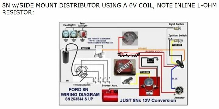
connections you described? I am attaching a link to
wiring diagram for Fords. The 2nd from the top is what
you should reference. I am not sure what type of
alternator you are using if it is a one wire you can
disregard any part of the circuits that are shown off
the P1 and P2 terminals on the alternator shown. I look
briefly at the video mostly to see the solenoid they
show and it was an original 3 terminal I described
above. Also I confirmed only one wire is connecting to
one side of the ammeter as I suggested is correct
above and as shown on the attached diagram.
Ford wiring diagrams