Panasonic DP-1820P Service Manual
Hide thumbs
Also See for DP-1820P:
- Quick manual (38 pages) ,
- Operating instructions manual (76 pages) ,
- Operating instructions manual (202 pages)
Table of Contents
Advertisement
Quick Links
This service information is designed for experienced repair technicians only and is not intended for use by the general public.
It does not contain warnings or cautions to advise non-technical individuals of potential dangers in attempting to service a product.
Products powered by electricity should be serviced or repaired only by experienced professional technicians. Any attempt to service
or repair the product or products dealt within this service information by anyone else could result in serious injury or death.
Digital Imaging Systems
DP-1520P/1820P/1820E
WARNING
© 2004 Panasonic Communications Co., Ltd.
All rights reserved. Unauthorized copying and distribution is
a violation of law.
Order Number: MGCS031201C0
[ Version 1.2 ]
H21
Advertisement
Table of Contents
Troubleshooting

Related Manuals for Panasonic DP-1820P


Summary of Contents for Panasonic DP-1820P
- Page 1 Products powered by electricity should be serviced or repaired only by experienced professional technicians. Any attempt to service or repair the product or products dealt within this service information by anyone else could result in serious injury or death. © 2004 Panasonic Communications Co., Ltd. All rights reserved. Unauthorized copying and distribution is...
- Page 2 URL: http://www.senju-m.co.jp) is recommended when repairing PbF PCBs. The contents of this Service Manual and the Specifications are subject to change without notice. Panasonic Communications Co., Ltd. reserves the right to make improvements in the product design without reservation and without notice. Published in Japan.
-
Page 3: Important Notice
Telephone Line Cable first before unplugging the AC Power Cord, if the Fax option is installed.) * The specifications are subject to change without notice. Panasonic Communications Co., Ltd. reserves the right to make improvements in the product design without reservation and without notice. - Page 4 Caution: Depending on your machine’s model, it may weight approximately 93.26 - 98.33 lb (42.3 - 44.6 kg) without any options. To prevent injuries, use the appropriate number of personnel and lift or move the machine as illustrated. Do not lift the machine by the Paper Tray as it may cause damage and/or bodily injury.
-
Page 5: For Your Safety
Precautions For Your Safety To prevent severe injury and loss of life, read this section carefully before servicing the Panasonic machine to ensure proper and safe operation. Please ensure that the machine is installed near a wall outlet and is easily accessible. -
Page 6: Operating Safeguards
Never touch a power cord with wet hands. Danger of electric shock exists. If the power cord is broken or insulated wires are exposed, replace immediately with a specified cord only. Using a damaged cord can cause fire or electric shocks. Stop operation immediately if your machine produces smoke, excessive heat, unusual noise, or smell, or if water is spilt onto the machine. -
Page 7: Consumable Safeguards
CAUTION Do not place a magnet near the safety switch of the machine. A magnet can activate the machine accidentally resulting in injuries. Do not use a highly flammable spray or solvent near the machine. It can cause fire. When copying a thick document, do not use excessive force to press it against the document glass. -
Page 8: Table Of Contents
(DA-NF180) for DP-1820P/1820E..335 3.4. Preventive Maintenance Check List ..99 8.6. Installing the Fax Communication Board 3.5. Resetting the P/M (DA-FG180) for DP-1820P/1820E ..339 (Preventive Maintenance) Counter ..101 8.7. Installing the Keyboard Option 3.6. Lubrication Point List ......102 (DA-KB180) for DP-1820P/1820E..349 3.7. -
Page 9: Table Of Contents
Table of Contents 8.16. Installing the Platen Cover (DA-UC200) for PU............386 8.17. Installing the Dehumidifier Heater Kit (DZTQ000074)........387 8.18. Installing the Dehumidifier Heater Kit for Paper Tray (DZHP009959)....398 8.19. Installing the Mechanical Counter (DZTK000002) ........406 8.20. Installing the Key Counter Harness Kit (DA-KH180) ..........410 8.21. -
Page 10: Specifications Table
DP-1520P/1820P/1820E 1 Specifications Table 1.1. Copy Function Copy Function Description Items Remarks DP-1520P DP-1820P DP-1820E Basic Specifications 1 Type Desktop 2 Platen Fixed 3 Original Position Platen Left / Rear ADF / i-ADF Left / Center 4 Recording Paper Path... - Page 11 DP-1520P/1820P/1820E Copy Function Description Items Remarks DP-1520P DP-1820P DP-1820E 16 Copy Speed Ledger / A3 9 cpm 11 cpm From Platen, Letter/A4 Portrait, 1st Legal / B4 / FLS 10 cpm 12 cpm Paper Tray, and Paper ejected to the...
- Page 12 DP-1520P/1820P/1820E Copy Function Description Items Remarks DP-1520P DP-1820P DP-1820E Options 1 Paper Feed System 550 sheets x 3 sheets x 1 550 sheets 2nd Motor is not mounted. Paper Tray Paper Size Detection Manual Manual Control Panel Selectable Low Level Paper...
- Page 13 DP-1520P/1820P/1820E Copy Function Description Items Remarks DP-1520P DP-1820P DP-1820E 4 ADF Single Side Type Option Original Set Face Up Scanning Method Sheet Through Capacity (Originals) 50 sheets LTR / A4 : 20 lb (75 g/m SADF Mode Free Stop From 30 to 70 degrees.
- Page 14 DP-1520P/1820P/1820E Copy Function Description Items Remarks DP-1520P DP-1820P DP-1820E Features 1 Automatic Features Auto Magnification Selection Using ADF only Auto Paper Selection Auto Paper Tray Selection Reservation while Power On Auto Start Initializing. Requires the Fax Communication Board (DA-FG180) option or the...
- Page 15 DP-1520P/1820P/1820E Copy Function Description Items Remarks DP-1520P DP-1820P DP-1820E Duplex Copy 1→2 2→1 Scanning twice by turning the original. 2→2 Book→2 1 → 2/2 → 1/2 → 2 1st Page BLANK Book → 2 1st Page IMAGE Image Rotation (90 or 270 °)
- Page 16 DP-1520P/1820P/1820E Copy Function Description Items Remarks DP-1520P DP-1820P DP-1820E Original Size Copy Size Keypad Clear Stop Start Energy Saver Multi Size Feed Sort Function Mode Original Detection Release Interrupt Reset One-Touch key With Keyboard Option Copier / Printer / NW Scanner / Fax...
- Page 17 DP-1520P/1820P/1820E Copy Function Description Items Remarks DP-1520P DP-1820P DP-1820E Paper Jam Indication Paper Jam Location Service Alert Call User Error Machine Error History of Jam Errors 4 Main Unit Total Counter Electronic Standard for EU. Mechanical Available as a Service Part for Other Destinations.
- Page 18 DP-1520P/1820P/1820E Copy Function Description Items Remarks DP-1520P DP-1820P DP-1820E PM Cycle 1 PM Cycle Major PM 120 K Minor PM (Cleaning) 60 K Packing Configuration 28.5 x 28.6 x 34.1 in For USA, Canada and China (724 x 727 x 866 mm) 1 Packing Dimension 28.4 x 28.4 x 29.5 in...
- Page 19 DP-1520P/1820P/1820E Copy Function Description Items Remarks DP-1520P DP-1820P DP-1820E Ambient Conditions 50 - 80 °F / 10 - 30 °C 1 Temperature 2 Relative Humidity 30 - 80% UL1950-1 / CSA C22.2 No.950 For USA and Canada 3 Safety EN60950-1...
-
Page 20: Fax, Printer And Internet Fax Functions
1.2. Fax, Printer and Internet Fax Functions 1.2.1. Fax Function Fax Function Description Items Remarks DP-1820P / 1820E Main Specifications 1 Compatibility ITU-T Std & Non-Std 2 PSTN Line Port 1-Line Only 3 Leased Line Port 4 V.24 Line Port 5 Modem Speed 33.6 - 2.4 kbps... - Page 21 DP-1520P/1820P/1820E Fax Function Description Items Remarks DP-1820P / 1820E 5 Document Size (Max.) ADF: LDR / A3 6 Effective Scanning Width LDR (11.5 in) / A3 (292 mm) 7 A3 size TX/RX Conforms to ITU-T A3 LDR to LTR / A3 to B4 / A3 to A4...
- Page 22 DP-1520P/1820P/1820E Fax Function Description Items Remarks DP-1820P / 1820E 8 Max. Station Name Characters Full Number Dialing Max. 50 stations (Buffered Dialing) 10 Direct Dialing Voice mode (Monitor Dialing) 11 Automatic Redialing Up to 15 times at 0 to 15 min. intervals...
- Page 23 DP-1520P/1820P/1820E Fax Function Description Items Remarks DP-1820P / 1820E 4 Overlap Printing Page End Approx. 0.51 in (13 mm) 5 Receive to Memory Distinctive Ring Detector (DRD) 90 Degree Rotation Reception 8 Duplex Printing Polling 1 Polling 2 Turnaround Polling Max.
- Page 24 DP-1520P/1820P/1820E Fax Function Description Items Remarks DP-1820P / 1820E Identifications 1 Logo 25 Characters 2 Multiple Logo 3 Character ID 16 Characters 4 Numeric ID 20 Digits Special Communications 1 Password XMT / RCV 2 Selective Reception TSI Check 3 Relay XMT Request...
- Page 25 DP-1520P/1820P/1820E 1.2.2. Printer Function Printer Function Description Items Remarks DP-1520P / 1820P / 1820E Interface 1 Centronics Parallel I/F Ethernet 10Base-T/ 2 LAN (Network) 100Base-TX 3 USB Port 4 IEEE-1394 Printer Function LDR, LGL, LTR, LTR-R, INV-R For USA and Canada 1 Printing Size A3, A4, A4-R, A5, A5-R, B4, FLS For EU A3, B4, A4, A4-R, B5, B5-R...
- Page 26 DP-1520P/1820P/1820E Printer Function Description Items Remarks DP-1520P / 1820P / 1820E Requires Optional PCL6 or PS / PCL6 19 Font Emulation Kit Requires Optional HDD Unit. 20 Mailbox Max. 100 Users. Max. 20 mailboxes for each User ID Requires Optional HDD Unit. 21 Secure Mailbox Max.
- Page 27 DP-1520P/1820P/1820E 1.2.3. Network Scanner Function Network Scanner Function Description Items Remarks DP-1820P / 1820E Interface 1 Centronics Parallel I/F Ethernet 10Base-T/ 2 LAN (Network) 100Base-TX 3 USB Port 4 IEEE-1394 Network Scanning Function 1 Scanning Device CCD (i-ADF / ADF / Platen) 600 x 600 : 2.1 sec...
- Page 28 DP-1520P/1820P/1820E 1.2.4. Internet Fax Function Internet Fax Function Description Items Remarks DP-1820P / 1820E Main Specifications 1 Communication Protocols SMTP / POP3 / MIME 2 Max. Modem Speed 3 Coding Scheme JBIG/MMR/MR/MH Selectable 4 File Format TIFF / PDF PDF file is only available if sending to PC (Network Scanner).
- Page 29 DP-1520P/1820P/1820E Internet Fax Function Description Items Remarks DP-1820P / 1820E LAN Features A3 Communication is available with 1 Internet Fax Communication Parameter setting. 2 Internet Mail Reception 3 Internet Fax Server Features Internet Fax → Internet Fax → G3FAX Internet Fax Relay XMT PC →...
-
Page 30: System Combination
DP-1520P/1820P/1820E 1.3. System Combination Inverting ADF (DP-1820E only) ADF PC Board Scanner Unit Document Sensor (SPC PC Board) Motor Panel Main PC Board PCL6 Fax Communication (PNL PC Board) (SC PC Board) Emulation Option Option (FXB/MJR) PS/PCL6 Printer Emulation Option Network Scanner Option Interface... -
Page 31: Options List
Platen Cover DA-UC200 Available in Specified Destinations Automatic Document Feeder DA-AS181 Inverting Automatic Document Feeder DA-AR202 4th Paper Tray is for DP-1820P/1820E 2nd / 4rd Paper Tray DA-DS184 only. 3rd Paper Tray is for DP-1820P/1820E 3rd Paper Tray DA-DS185 only. -
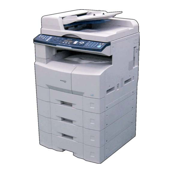
Page 32: External View
DP-1520P/1820P/1820E 1.5. External View 1. Standard Configuration (For USA Only) Complies with FDA radiation performance standards, 21 CFR Subchapter J Factory ID Manufacturer's Name and Address Top View 21.97 in (558 mm) 21.54 in (547 mm) Rear View Right View Left View Front View For USA, Canada and Europe... - Page 33 DP-1520P/1820P/1820E 2. With Optional System Console Configuration Top View 24.76 in (629 mm) 21.97 in (558 mm) Rear View Right View Left View Front View Ver. 1.2 SEP 2004...
- Page 34 DP-1520P/1820P/1820E 3. Space Requirements With Options Main Unit 3.94 in (100 mm) 10.83 in (275 mm) 21.97 in (558 mm) 16.14 in (410 mm) 3.94 in (100 mm) 40.67 in (1033 mm) Main Unit + ADF 3.94 in (100 mm) 10.83 in (275 mm) 21.97 in (558 mm)
- Page 35 Model Number and Destination Code (Main Unit) 3-Digit number or alphanumeric representation (Except Letters I and O ) For Example: = DP-1520P-PU 3SK = DP-1520P-PB = DP-1820P- PU 3SM = DP-1820P-PB 3SP = DP-1820E-PU 3SV = DP-1820E-PB Production Facility Production Year...
-
Page 36: Control Panel
1.6. Control Panel For USA and Canada DP-1520P DP-1820P DP-1820E OPTIONS (DP-1820P/1820E only) Included with Fax, Internet / E-Mail and Network Scanner Options Note: LCD Display Brightness Adjustment To adjust the brightness of the LCD display, press and while holding down the "CLEAR" key, keep pressing the "ORIGINAL SIZE"... - Page 37 DP-1520P/1820P/1820E For Other Destinations DP-1520P DP-1820P DP-1820E OPTIONS (DP-1820P/1820E only) Included with Fax, Internet / E-Mail and Network Scanner Options Ver. 1.2 SEP 2004...
-
Page 38: Sensors
DP-1520P/1820P/1820E 1.7. Sensors ADF Original Length Sensor 1 (131) ADF Sensor 1 (131) ADF Original Length Sensor 2 (131) ADF Sensor 2 (131) ADF Sensor 3 (131) ADF Cover Open Sensor (131) Home Position Sensor (131) Fuser Unit Sensor (131) Sheet Bypass Sensor 1 (131) Registration Sensor (131) Sheet Bypass Sensor 2 (131) -
Page 39: Clutches And Switches
DP-1520P/1820P/1820E 1.9. Clutches and Switches ADF Roller Clutch (2324) Intermediate Clutch (2632) Feed 2 Roller Clutch (2325) Interlock Switch (227) Registration Roller Clutch (694) Heater Switch (814) Paper Feed Roller Power Switch (818) Clutch (695) Paper Feed Roller Clutch (695) Intermediate Roller Clutch (694) 1.10. -
Page 40: Disassembling, Cleaning And Replacement
DP-1520P/1820P/1820E 2 Disassembling, Cleaning and Replacement 2.1. General Disassembly Pertinent Disassembly Instruction sections are shown below. Ver. 1.2 SEP 2004... -
Page 41: Disassembly Instructions
DP-1520P/1820P/1820E 2.2. Disassembly Instructions 2.2.1. Inverting-Automatic Document Feeder (i-ADF) Unit (1) Open the ADF Cover (2126). (2) Remove 4 Silver Screws (B1). (3) Lift the ADF Input Tray (2201). (4) Slightly pull the right edge of the ADF Rear Cover upward. (5) Release the Latch Hooks. - Page 42 DP-1520P/1820P/1820E (15) Remove the Snap Ring (S9). (16) Remove the Pin (2327). (17) Remove the ADF Shaft (2310). (18) Remove the ADF Roller (2314). (19) Remove the Snap Ring (S9). (20) Remove the Pre Feed Roller Shaft (2316). (21) Remove the Pre Feed Roller (2018). (22) Remove 1 Silver Screw (B1).
- Page 43 DP-1520P/1820P/1820E (26) Remove the Snap Ring (S9). (27) Remove the Torque Limiter Bushing (2510) and Torque Limiter Spring (2511). Note: When reinstalling the Torque Limiter Assembly, ensure that the Torque Limiter Spring is placed into the deeper slot of the Separation Roller. <Cleaning Torque Limiter Bushing and Torque Limiter Spring>...
- Page 44 DP-1520P/1820P/1820E (35) Remove 6 Screws (19). (36) Remove the Sensor Bracket (2120). (37) Remove 4 Screws (19). (38) Remove the Motor Bracket (2610) and Gear Bracket (2602) Assemblies. Note: Apply Molykote EM-50L Grease to all Gears and Shafts except to the following: E26S35 Drive Gear (2604), ADF Motor (2601), and the shafts of Drive Shaft 2 (2615) and Exit 3 Roller (2515).
- Page 45 DP-1520P/1820P/1820E 2.2.2. ADF Unit (1) Open the ADF Cover (1902) and release the ADF Cover Stopper (2013). (2) Remove the Pad Cover (2023). (3) Remove the Separation Rubber (2024). (4) Remove 2 Screws (19). (5) Remove the ADF Cover (1902). (6) Disconnect the ADF Motor Harness (2848).
- Page 46 DP-1520P/1820P/1820E (10) Remove 2 Bushings (698). (11) Remove Roller Holder (2026) Assembly. Note: When reinstalling, make sure that the Roller Holder (2026) Assembly is properly placed on the ADF Unit. (12) Remove the Paper Feed Shaft Assembly (2029). (13) Remove Paper Feed Roller (2001) and D26 D Gear (2025).
- Page 47 DP-1520P/1820P/1820E Note: When reinstalling the ADF Rear Cover (1701), make sure to properly route the ADF Harness as illustrated. (17) Remove 1 Screw (19). (18) Remove the ADF PC Board Cover (1916). (19) Release the Clamp from ADF Unit. Note: Do not cut the Tie-Wrap.
- Page 48 DP-1520P/1820P/1820E (23) Open the ADF Unit. (24) Remove 4 Screws (6A). Caution: Don’t close the ADF Unit subsequent to this step. (25) Remove the ADF Unit. (26) Disconnect 5 Harnesses (2848, 2849, 2850, 2851) on the ADF PC Board. (5 connectors) (27) Remove 2 Screws (19).
- Page 49 DP-1520P/1820P/1820E (33) Remove 2 Screws (18). (34) Remove the ADF Motor (1905). (35) Remove 2 Drive Belts (1911, 1912). (36) Remove the S27 Pulley (1910). (37) Remove the Snap Ring (B9). (38) Remove the S27 Pulley (1910). (39) Release the clips and remove the Switch (1918).
- Page 50 DP-1520P/1820P/1820E <Turn the ADF upside down> (41) Detach the Hook and Loop Fastener on the left side of the Scanning Pad (1822). (42) Remove 1 Screw (19). (43) Remove the Exit 1 Roller (1812) and P6L8 Bushing (1813). <Return the ADF to its upright position> (44) Release 2 Latch Hooks.
- Page 51 DP-1520P/1820P/1820E (50) Remove the Snap Ring (B9). (51) Remove the Bushing (698). (52) Remove the Feed Roller (2010). <Cleaning the Rollers and Rubber> (1) Open the ADF Cover. (2) Release the Stopper. (3) Clean the Separation Rubber, Feed Roller, Pre Feed Roller and Paper Feed Roller with a soft cloth, saturated with isopropyl alcohol.
- Page 52 DP-1520P/1820P/1820E <Cleaning the Scanner> (1) Open the ADF Unit. (2) Clean the White Guide, Scanning Pad, Scanning (S) Glass, and Platen (L) Glass with a soft cloth, saturated with isopropyl alcohol. Note: Ensure that the Clear Film as illustrated by A is not damaged.
- Page 53 DP-1520P/1820P/1820E 2.2.3. Control Panel Unit, Battery <Replace the Battery> (1) Remove 1 Screw (Q8). (2) Remove the Battery Holder (503). (3) Replace the Battery (504). Note: Ensure that the battery is installed with correct polarity. (4) Reinstall the Battery Holder (503) and the Screw (Q8).
- Page 54 DP-1520P/1820P/1820E (14) Disconnect all the Harnesses on PNL1 PC Board. (15) Release the Harnesses from 2 Harness Clamps. (16) Remove the Harness Protection Cover (518). (17) Disconnect the Harness on PNL1 PC Board as illustrated. (18) Remove 2 Screws (X8). (19) Remove the PNL1 PC Board (2904).
- Page 55 DP-1520P/1820P/1820E (20) Remove 8 Screws (X8). (21) Remove the PNL 2 PC Board (2905) as illustrated. (22) Remove 10 Screws (X8). (23) Remove the PNL 3 PC Board (2906) as illustrated. (24) Remove the LCD Holder (520). (25) Remove the LCD Module (519). Ver.
-
Page 56: Scanner Unit
DP-1520P/1820P/1820E 2.2.4. Scanner Unit (1) Remove the Control Panel Assembly. (Refer to 2.2.3.) (2) Remove 4 Shoulder Silver Screws (X2). (3) Remove the Rear Document Plate (107). (4) Remove the Platen (L) Glass (106). (5) Holding by the center, slowly move the Lamp Base Assembly to the center of the Scanner Base Frame in the direction shown by the arrow. - Page 57 DP-1520P/1820P/1820E (10) Slide the Lamp Base Assembly to the right side as illustrated. (11) Release the Harness. Note: When reinstalling the Harness, confirm that the Harness is installed as illustrated. (12) Slide the Lamp Base Assembly to the right side as illustrated.
- Page 58 DP-1520P/1820P/1820E (16) Remove 2 Screws (X3). (17) Remove the CCD Assembly (427). Note: Before proceeding, mark the position of the CCD Assembly as illustrated. If the CCD Assembly is not reinstalled at the same position, it will affect the copy quality. (18) Remove 2 Shoulder Silver Screws (X2).
- Page 59 DP-1520P/1820P/1820E (22) Disconnect the Harness. (23) Remove 2 Screws (Y3). (24) Remove the Scanning Motor (316). (25) Remove 5 Shoulder Silver Screws (X2). (26) Remove the Left Document Plate (109). Note: When reinstalling the Left Document Plate, ensure the Scanning (S) Glass is in its original position against the key as illustrated.
- Page 60 DP-1520P/1820P/1820E (27) Clean the White Reference Sheet with a soft cloth, saturated with isopropyl alcohol. (28) Clean both Mirror 2 (421) with a soft cloth, saturated with isopropyl alcohol. (29) Clean the Mirror 1 (415) with a soft cloth, saturated with isopropyl alcohol. Ver.
- Page 61 DP-1520P/1820P/1820E 2.2.5. Process Unit Note: To avoid Toner spill in the machine, follow the steps below before removing the Process Unit. 1. Press "FUNCTION" and "1 SIDED COPY" keys simultaneously. 2. The LCD shows “Please wait...” for approx. 5 sec. Then it will be ready. (1) Open the Left Cover.
- Page 62 DP-1520P/1820P/1820E (5) Remove 1 Screw (Y3). (6) Remove the Connector Cover (203). (7) Loosen 1 Screw. (8) Disconnect the Harness. (9) Remove the Process Unit. Caution: To prevent damage to the Process Unit, ensure that the Left Cover is still open before removing the Process Unit out of the machine.
- Page 63 DP-1520P/1820P/1820E (12) Turn the OPC Drum Assembly in the direction of the arrow and remove. Caution: Exercise caution not to scratch the surface of the OPC Drum (Green), and not to touch it with bare hands. Caution: The OPC Drum is sensitive to light. To prevent optical exposure problems, do not expose the OPC Drum to direct sunlight or bright light.
- Page 64 DP-1520P/1820P/1820E (17) Shake the Developer Bottle thoroughly (approx. 30 seconds). (18) Pour the developer evenly into the developer unit by turning the Black Gear as illustrated. Make sure to empty the bottle. <Removing the Old OPC Drum> (19) Remove the OPC Drum Shaft Holder Assembly.
- Page 65 DP-1520P/1820P/1820E (24) Remove the Charge Grid (1433). (25) Remove 2 Charge Cover (1432,1438). (26) Draw out the Cleaning Lever Handle (Green) (1427). (27) Remove the Charge Cleaning Base (1439). (28) Remove the Charge Wire Assembly. Ver. 1.2 SEP 2004...
- Page 66 DP-1520P/1820P/1820E (29) Remove the Pad Base (1441). (30) Remove 2 Screws (X3). (31) Remove the Cleaning Blade (1408). (32) Remove the Front Cleaning Felt (1410), Rear Cleaning Felt (1411) and 2 Cleaning Sponges (1412). (33) Remove the Sheet Scoop (1415). Ver.
-
Page 67: Fuser Unit
DP-1520P/1820P/1820E 2.2.6. Fuser Unit CAUTION: To prevent from getting burned, do not install, remove, clean or make adjustments when the Fuser Unit is hot. (1) Open the Left Cover. (2) Remove 2 Screws (X8). (3) Remove the Rear Fuser Cover (1006) and the Front Fuser Cover (1007). - Page 68 DP-1520P/1820P/1820E (8) Disconnect the Harness. (9) Remove 2 Screws (X8). (10) Remove the Upper Fuser Cover Assembly. <Cleaning Exit 2 Roller> Clean the Exit 2 Roller with a soft cloth, saturated with isopropyl alcohol. (11) Unhook 2 Springs. Ver. 1.2 SEP 2004...
- Page 69 DP-1520P/1820P/1820E (12) Remove 2 Screws (X3). (13) Release 2 Harnesses. (14) Remove 2 Screws (X8). (15) Remove the Exit Roller Cover (1101). (16) Remove 4 Screws (X7). (17) Remove the Fuser Roller (1115) Assembly. (18) Remove 1 Screw (X8). (19) Remove the Front Lamp Holder (1123). (20) Remove the Fuser Lamp (1116).
- Page 70 DP-1520P/1820P/1820E (23) Remove 2 Screws (X8). (24) Remove the Finger Base (1108) Assembly. (25) Remove 5 Separators (1109). <Cleaning Separators> Clean the Separators with a soft cloth, saturated with isopropyl alcohol. (26) Remove the Fuser Roller (1115) Assembly. (27) Remove the 2 C-Rings (1113). (28) Remove the E39 Heat Roller Gear (1112).
- Page 71 DP-1520P/1820P/1820E (30) Remove 2 Screws (X3). (31) Remove the Thermostat (1120). (32) Remove 2 Screws (X3). (33) Remove the Thermal Fuse (1118). (34) Remove 1 Screw (X1). (35) Remove the Thermistor Assembly (1125). <Cleaning Thermostat> Clean the surface of the Thermostat only with a soft dry cloth.
-
Page 72: Drive Unit
DP-1520P/1820P/1820E 2.2.7. Drive Unit 2.2.7.1. Drive Motor and Toner Bottle Motor (1) Remove 10 Screws (Y3). (2) Remove the Rear Cover (220). (3) Remove 1 Screw (24). (4) Remove the Fly Wheels (1555). (5) Disconnect the Harnesses on the SPC PC Board (CN719, CN721 and CN723) and Main Motor. - Page 73 DP-1520P/1820P/1820E (10) Remove 4 Screws (Y3). (11) Remove the Main Drive Frame B. (12) Remove 2 Snap Rings (S9). (13) Release the Harnesses from 3 Harness Clamps. (14) Remove 2 Clutches (694, 695). (15) Slide the 1st Paper Tray out of the unit. (16) Remove 3 Screws (Y3).
- Page 74 DP-1520P/1820P/1820E (20) Remove 4 Screws (X8). (21) Remove the Drive Motor (1511). (22) Disconnect all the Harnesses on the SPC PC Board. (23) Release the Harnesses from Harness Clamps. Note: When reinstalling the ILS Harness (SPC PC Board CN708), ensure that it is secured by the Harness Clamp as illustrated.
- Page 75 DP-1520P/1820P/1820E (31) Remove 4 Screws (Y3). (32) Remove the SPC Bracket (926). (33) Release the Harnesses from Harness Clamps. (34) Remove 3 Screws (Y3). (35) Remove the Toner Bottle Motor Unit. (36) Disconnect the Harness. Ver. 1.2 SEP 2004...
- Page 76 DP-1520P/1820P/1820E 2.2.7.2. Lift Up Motor and 3rd Main Motor (1) Remove 10 Screws (Y3). (2) Remove the Rear Cover (220). (3) Remove 4 Silver Screws (1027). (4) Remove the Rear Paper Tray Cover (3004). (5) Remove 4 Silver Screws (1027). (6) Remove the Rear Paper Tray Cover (3004).
- Page 77 DP-1520P/1820P/1820E (16) Release the Harnesses from 2 Harness Clamps. (17) Disconnect the Harness on the CST2 PC Board (CN774). (18) Remove 2 Screws (Y3). (19) Remove the Lift Up Motor (3132). (20) Release the Harnesses from 2 Harness Clamps. (21) Disconnect the Harness on the CST2 PC Board (CN774).
- Page 78 DP-1520P/1820P/1820E 2.2.8. Left Cover (1) Open the Left Cover. (2) Remove 4 Screws (Y3). (3) Remove the ADU. (4) Remove 2 Screws (X8). (5) Remove the Bias Transfer Guide (701). (6) Remove the E-Ring (J6). (7) Remove the BTR Ring Spacer (705). (8) Remove the BTR 27 Gear (706).
- Page 79 DP-1520P/1820P/1820E (11) Remove 2 Bias Transfer Roller Bushings (709). <Cleaning Bias Transfer Roller> Clean the surface of the Bias Transfer Roller only with a soft dry cloth. <Cleaning Duplex Feed Rollers> Clean the surface of the Duplex Feed Roller with a soft cloth, saturated with isopropyl alcohol.
- Page 80 DP-1520P/1820P/1820E 2.2.9. Bypass Paper Tray (1) Open the Left Cover. (2) Remove 2 Screws (X8). (3) Remove the Duplex Guide (638) Assembly. (4) Remove 2 Screws (X8). (5) Remove the Feed Roller (689) Assembly. (6) Remove the Snap Ring (S9). (7) Remove the Bushing (642).
- Page 81 DP-1520P/1820P/1820E (10) Remove 1 Screw (X8). (11) Remove the Guide (659). (12) Remove the Separation Roller (658) Assembly. (13) Remove the Bushing (651). (14) Remove the Torque Limiter 2 (691). (15) Remove the Separation Roller (658). <Cleaning Separation Roller> Clean the surface of the Separation Roller with a soft cloth, saturated with isopropyl alcohol.
-
Page 82: Paper Feed Module
DP-1520P/1820P/1820E 2.2.10. Paper Feed Module (1) Slide the 1st Paper Tray out of the unit. (2) Remove the Snap Ring (H6). (3) Remove the Pickup Roller (619). <Cleaning Pickup Roller> Clean the surface of the Pickup Roller with a soft cloth, saturated with isopropyl alcohol. - Page 83 DP-1520P/1820P/1820E (10) Slide the 2nd Paper Tray out of the unit. (11) Open the Jam Access Cover (3015). (12) Remove 3 Screws (Y3, X8). (13) Remove the Paper Guide (3022). (14) Remove the Snap Ring (H6). (15) Remove the Separation Roller (629) Assembly. (16) Remove the Torque Limiter 1 (690).
- Page 84 DP-1520P/1820P/1820E (20) Remove the Snap Ring (H6). (21) Remove the Pickup Roller (619). <Cleaning Pickup Roller> Clean the surface of the Pickup Roller with a soft cloth, saturated with isopropyl alcohol. <Cleaning Intermediate Roller> Clean the surface of the Intermediate Roller with a soft cloth, saturated with isopropyl alcohol.
- Page 85 DP-1520P/1820P/1820E 2.2.11. PC Boards and Power Supply PC Boards <SC PC Board> (1) Remove the Rear Cover and Lower Rear Cover (Refer to 2.2.7.2.). (2) Remove 1 Screw (Y3). (3) Remove the LAN Spring (812). (4) Remove the Process Unit (Refer to 2.2.5.). (5) Slide the 1st Paper Tray out of the unit.
- Page 86 DP-1520P/1820P/1820E (12) Disconnect all the Harnesses on the SC PC Board. (13) Remove 8 Screws (Y3). (14) Remove the SC PC Board (2801). <SPC PC Board> (15) Disconnect all the Harnesses on the SPC PC Board. (16) Release the Harnesses from Harness Clamps. Note: When reinstalling the ILS Harness (SPC PC Board CN708), ensure that it is secured by the Harness...
- Page 87 DP-1520P/1820P/1820E <Power Supply PC Boards> (20) Remove the Inner Cover (219). (21) Remove 6 Screws (Y3). (22) Remove the Right Bracket (803). (23) Remove 6 Screws (X3). (24) Remove the PS Cover (801). Note: When reinstalling the PS Cover, ensure that the PS Cover is installed into the Ground Plate as illustrated.
- Page 88 DP-1520P/1820P/1820E (28) Disconnect all the Harnesses on the PS PC Board. (29) Release the Harnesses from Harness Clamps. (30) Remove 2 Screws (X3). (31) Remove the PS PC Board Assembly. (32) Remove 3 Screws (Y3) and 3 Screws (X3). (33) Remove the PS Bracket (802). (34) Remove 9 Screws (Y3).
-
Page 89: Lsu Unit
DP-1520P/1820P/1820E 2.2.12. LSU Unit (1) Remove the PS PC Board Assembly. (Refer to 2.2.11.) (2) Disconnect 3 Harnesses. (3) Release the Harnesses from Harness Clamps. (4) Remove 3 Screws (X3). (5) Remove the LSU Unit (829). Ver. 1.2 SEP 2004... - Page 90 DP-1520P/1820P/1820E 2.2.13. Filter (1) Remove the Rear Cover (Refer to 2.2.7.). (2) Remove the Ozone Filter (825). (3) Remove the Filter Holder (824). Ver. 1.2 SEP 2004...
-
Page 91: Hardware Identification Template
DP-1520P/1820P/1820E 2.3. Hardware Identification Template Ref. No. Part No. Figure Remark XYN3+J6 Screw XTB3+8J Screw XYN4+F8 Screw XTB3+6J Screw XTB4+8J Screw XYN3+F5 Screw XYN3+F4 Screw XUC4 E-Ring XUC6 E-Ring XTB3+12J Screw DZPB000007 Silver Screw XTB3+8JK Blue Screw DZJM000171 Snap Ring DZPB000020 Screw XTW3+10S... - Page 92 DP-1520P/1820P/1820E Ref. No. Part No. Figure Remark FFPFJ0033 Snap Ring FFPFJ0041 Snap Ring XUC3VM E-Ring XUC4VM E-Ring XUC7VM E-Ring XUC5VM E-Ring FFPFJ0043 Snap Ring DZPA000064 Thumb Screw Screw XTB3+12J XTB3+8GFN Screw DZPA000086 Screw DZJM000171 Snap Ring XTB3+12JFJ Screw XTB3+10GFJ Screw Screw DZPA000089 XYN3+F8FJ...
- Page 93 DP-1520P/1820P/1820E Ref. No. Part No. Figure Remark XYN3+F14FJ Screw XTB3+8GFJ Screw XTB3+8FFJ Screw XTW3+8PFJ Screw XTB3+6FFJ-RP Screw XTW3+6LFJ Screw XTB3+32GFJ Screw Screw XSN3+W10FJ XTW3+6LFJR Screw XNC3FJ XTN3+10GFJ Screw XYN4+F8FJ Screw XYN4+F6FJ Screw XSB4+10FN Screw Ver. 1.2 SEP 2004...
-
Page 94: Maintenance, Adjustments And Check Points
DP-1520P/1820P/1820E 3 Maintenance, Adjustments and Check Points 3.1. Preventive Maintenance Preventive maintenance is performed at specific intervals and consists of machine cleaning and parts replacement. It is essential to perform these service activities properly and at the specified intervals for customer satisfaction. The purpose of this service is to maintain machine performance and image quality. - Page 95 DP-1520P/1820P/1820E Laser Handling Precautions The optical laser system employed by this photocopier is completely sealed by a protective housing and an external cover. Therefore, the laser beam will not stray or leak during photocopying operation. However, when servicing the photocopier, take the following precautions: 1.
-
Page 96: Required Tools
DP-1520P/1820P/1820E 3.2. Required Tools Tools Tools Soft Cloth Pliers Isopropyl Alcohol Cotton Swab Phillips Screwdriver (#2) Brush KS-660 - Conductive Grease Stubby Phillips Screwdriver (#2) (Available from Shin-Etsu Silicones of America, Inc. URL: http://www.shinetsusilicones.com) Molykote EM-50L Grease Slotted Screwdriver (3/32 in) (Available from Dow Corning, URL: http://www.dowcorning.com) Tweezer... -
Page 97: Preventive Maintenance Points
DP-1520P/1820P/1820E 3.3. Preventive Maintenance Points i-ADF 8 11 37 39 36 38 41 DETAIL A 18 19 23 24 18 19 18 19 18 19 Ver. 1.2 SEP 2004... - Page 98 DP-1520P/1820P/1820E 32 33 34 DETAIL A Ver. 1.2 SEP 2004...
-
Page 99: Preventive Maintenance Check List
DP-1520P/1820P/1820E 3.4. Preventive Maintenance Check List The chart outlined below is a general guideline for maintenance. Cleaning Replacement/Adjustment Ref. Ref. Mechanical Parts Cycle Cycle Counter Method Procedure (Sheet) (Sheet) i-ADF Unit 1 ADF Roller 2314 Alcohol 120K Refer to F7-08 2.2.1. - Page 100 To verify the counter information, print the Total Counter List using the Service Mode: F7 - Electronic Counter - 00 (List Print). 3. Cleaning, Replacement and Adjustment Cycle (Sheet) are based on using Panasonic's recommended standard paper and supplies. These cycles may vary with the kind of paper used, Paper size, orientation, print duty, continuous/interval print and/or ambient conditions.
-
Page 101: Resetting The P/M Preventive Maintenance) Counter
DP-1520P/1820P/1820E 3.5. Resetting the P/M (Preventive Maintenance) Counter When the machine reaches the preset P/M Cycle, it will show "Call for P/M" or "Replace The Toner Waste Container" on the LCD Display. The PM Counter can be reset by following the procedures below. 3.5.1. -
Page 102: Lubrication Point List
DP-1520P/1820P/1820E 3.6. Lubrication Point List This information is used for routine Preventive Maintenance (PM) calls to ensure the highest degree of reliability. Inspect the following areas and lubricate as required. The inspection interval is usually 120K copies or more, however the interval may be reduced due to environmental conditions. Ref. -
Page 103: Updating The Firmware
Tool (FUP) using Ethernet LAN Port and a Crossover Cable. The Network FUP Tool version must be 3.XX or higher, and it can be found on the Panasonic Document Management System CD-ROM included with the main unit or on the CD-ROM included with the PCL or PS/PCL options. - Page 104 DP-1520P/1820P/1820E When using 4 MB Flash Memory Card, the 8 MB program (C) must be divided onto 2 cards, one 4 MB card for the PCL Control Program (3) and one 4 MB card for the PCL Font data (4). (3) For PS Option The PS Control Program must be written into the 4 MB onboard, which is assigned as ROM Code (D).
- Page 105 4) Upgrading the Main Unit's Firmware Code Start the Network Firmware Update Tool and select the following Firmware Code Folders in the C:\Program Files\Panasonic\Panasonic-FUP\Data folder, and then follow the display instructions to upgrade the Main Unit's Firmware Codes. Parent Firmware File Folder...
- Page 106 Destination Shortcut Batch File: D:(CD-ROM Drive) \ xFirmware \ USA.bat Firmware Code File: DP-1520_1820_PU_xxxxxx.exe Firmware Data Folder: C:\ Panasonic \ Panasonic-FUP \ Data 3) Preparing the Main Unit for the Firmware Upgrade Important: DO NOT connect the USB Cable yet. Print the F5/F6 Parameters List (Copier Service Mode F9-03-00).
- Page 107 4) Upgrading the Main Unit's Firmware Code Start the Local Firmware Update Tool and select the following Firmware Code Parent File Folder in the C:\Panasonic\Panasonic-FUP\Data folder, and select the Firmware Code Type then follow the display instructions to upgrade the Main Unit's Firmware Codes.
- Page 108 Firmware Code File: DP-1520_1820_PU_xxxxxx.exe Firmware Data Folder: C:\ Panasonic \ Panasonic-FUP \ Data 3) Preparing the Main Unit for the Programming Master Firmware Card Important: DO NOT connect the USB Cable yet. 1. Turn the Power Switch on the Right side of the machine to the OFF position. (During a Lightning Storm, to prevent electrocution disconnect the Telephone Line Cable first before unplugging the AC Power Cord, if the Fax Option is installed.)
- Page 109 DP-1520P/1820P/1820E B. Copying the Firmware from an Existing Machine using a Flash Memory Card (4 MB or 8 MB) 1. Turn the Power Switch on the Right side of the machine to the OFF position. (During a Lightning Storm, to prevent electrocution disconnect the Telephone Line Cable first before unplugging the AC Power Cord, if the Fax Option is installed.) 2.
- Page 110 DP-1520P/1820P/1820E 3.7.8. Firmware Emergency Recovery The easiest method to recover the firmware in an Emergency Recovery routine is to either use the Local Firmware Update Tool software by selecting the Independent File method, or using the Master Firmware Flash Card method (2 Flash Cards required). Whichever method you select, it is easier to restore the machine's firmware to the Standard (AAV) Type first as it only requires 2 files to bring the machine to initial working condition.
-
Page 111: Firmware Version
DP-1520P/1820P/1820E 3.7.9. Firmware Version DP-LLNew A A Vxxxxx (AU) Destination Code (Fax) AU : USA/Canada AB : UK Destination Code (Copier) PU : USA/Canada PB : UK Division Soft (When it is divided into (a) and (b)) Firmware Version (V1xxxx) Language Code A : A-English, C-French &... - Page 112 DP-1520P/1820P/1820E 3.8. Copy Quality Adjustment Procedure (Order) Ver. 1.2 SEP 2004...
- Page 113 DP-1520P/1820P/1820E Note: 1. Print F5/F6 1) Press “FUNCTION”, “ORIGINAL SIZE”, and “3” keys sequentially to enter the Service Mode. 2) Press the "9" key to enter the F9 Mode (Unit Maintenance). 3) Press the "START" key. 4) Press "3" and "SET" keys. 5) Press "V"...
- Page 114 DP-1520P/1820P/1820E 3. PWM Adjustment 1) Ensure that Ledger / A3 Size Paper is loaded in one of the Trays, and pull out the remaining trays (including the bypass tray) to disable them. 2) Press “FUNCTION”, “ORIGINAL SIZE”, and “3” keys sequentially to enter the Service Mode. 3) Press the "8"...
-
Page 115: Adjusting The Printer Registration Lsu Image Side To Side
DP-1520P/1820P/1820E 3.9. Adjusting the Printer Registration, LSU Image Side to Side When installing the Paper Tray option, the following LSU Image Side to Side adjustment must be performed. The Printer registration is adjusted at the factory. If copy image is abnormal, specially in the Rotation Copy mode, adjust it by the following procedure. 3.9.1. - Page 116 DP-1520P/1820P/1820E 3.9.3. LSU Image Side to Side Adjustment for the ADU 1. Insert paper into the 1st tray and change the tray setting to the appropriate paper size. Empty or pull out all the remaining trays (including the bypass tray) to disable them. 2.
- Page 117 DP-1520P/1820P/1820E 3.9.6. ADF 100% Image 1-Sided Adjustment 1. Place the Original Document on the ADF. 2. Insert Ledger or A3 size paper into the 1st tray and change the tray setting to the appropriate paper size. Empty or pull out all the remaining trays (including the bypass tray) to disable them. 3.
- Page 118 DP-1520P/1820P/1820E 3.9.8. Double Exposure Lead and Side Edge Adjustments Caution: Confirm that the Scanning Pad is installed and aligned correctly on the ADF/i-ADF prior to making any adjustments. (Refer to the ADF/i-ADF Installation Instructions in Sect. 8.13. or 8.14.) 1. Place a Business Card, Driver's License, Insurance Card, etc. (Invoice size or smaller) on the Platen Glass as illustrated.
-
Page 119: Troubleshooting
DP-1520P/1820P/1820E 4 Troubleshooting 4.1. Initial Troubleshooting Flowchart START Plug the Power Cord in and turn the Power Switche ON. Does the unit power up normally? Does the LCD display the function correctly? Troubleshoot Improper LCD Display Troubleshoot any 3-digit CODE displayed Does the unit produce normal copies? Does the original document... -
Page 120: Improper Lcd Display
DP-1520P/1820P/1820E 4.2. Improper LCD Display START Check connectors: CN52 (SC PCB) and CN220 (PNL1 PCB). Does the display appear normal? Is LED/LCD displayed? Does CN52, pin 6 on the SC PCB measure +5 VDC? Replace the LCD Replace the SC PCB. Module. -
Page 121: Printed Copy Quality Problems
DP-1520P/1820P/1820E 4.3. Printed Copy Quality Problems 4.3.1. Black Copy START Is the Test Pattern printout in Copier F1 Mode or Fax Service Mode 3 normal? Check the Scanner mechanism. Is the OPC Drum/Developer Unit operational? Replace the OPC Drum/Developer Unit. Is the PS normal? 1. - Page 122 DP-1520P/1820P/1820E 4.3.2. Blank Copy START Is the Test Pattern printout in Copier F1 Mode or Fax Service Mode 3 normal? Check the Scanner mechanism. Is the OPC Drum/Developer Unit operational? Replace the OPC Drum/Developer Unit. Are there any foreign particles or stains in the Charge Unit? 1.
-
Page 123: Vertical White Lines
DP-1520P/1820P/1820E 4.3.3. Vertical White Lines START Is the Test Pattern printout in Copier F1 Mode or Fax Service Mode 3 normal? Check the Scanner mechanism. Is the recording paper damp? Replace the recording paper. Is the OPC Drum/Developer Unit operational? Replace the OPC Drum/Developer Unit. -
Page 124: Ghost Images
DP-1520P/1820P/1820E 4.3.4. Ghost Images A A A START Is the Test Pattern printout in Copier F1 Mode or Fax Service Mode 3 normal? Check the Scanner mechanism. Is the recording paper damp? Replace the recording paper. Is the OPC Drum/Developer Unit operational? Replace the OPC Drum/Developer Unit. - Page 125 DP-1520P/1820P/1820E 4.3.5. Vertical Dark Lines START Is the Test Pattern printout in Copier F1 Mode or Fax Service Mode 3 normal? Check the Scanner mechanism. Is the OPC Drum/Developer Unit operational? Replace the OPC Drum/Developer Unit. Is the LSU normal? Replace the LSU.
- Page 126 DP-1520P/1820P/1820E 4.3.6. Horizontal Dark Lines START Is the Test Pattern printout in Copier F1 Mode or Fax Service Mode 3 normal? Check the Scanner mechanism. Is the OPC Drum/Developer Unit operational? Replace the OPC Drum/Developer Unit. Is the LSU normal? Replace the LSU.
- Page 127 DP-1520P/1820P/1820E 4.3.7. Dark Background START Is the Test Pattern printout in Copier F1 Mode or Fax Service Mode 3 normal? Check the Scanner mechanism. Is the recording paper damp? Replace the recording paper. Is the OPC Drum/Developer Unit operational? Replace the OPC Drum/Developer Unit. Is the LSU normal? Replace the LSU.
-
Page 128: Light Print
DP-1520P/1820P/1820E 4.3.8. Light Print START Is the Test Pattern printout in Copier F1 Mode or Fax Service Mode 3 normal? Check the Scanner mechanism. Is the recording paper damp? Replace the paper. Is the OPC Drum/Developer Unit operational? Replace the OPC Drum/Developer Unit. Are there any foreign particles or stains blocking the Laser Unit 1. -
Page 129: Horizontal White Lines
DP-1520P/1820P/1820E 4.3.9. Horizontal White Lines START Is the Test Pattern printout in Copier F1 Mode or Fax Service Mode 3 normal? Check the Scanner mechanism. Is the recording paper damp? Replace the recording paper. Is the OPC Drum/Developer Unit operational? Replace the OPC Drum/Developer Unit. - Page 130 DP-1520P/1820P/1820E 4.3.10. Improper Fusing (Printed image does not bond to the paper) START Is the recording paper damp? Replace the recording paper. Is the Fuser Unit normal? Replace the Fuser Unit. (See Note) Note: Replace the entire Fuser Unit when the Thermostat and/or the Thermistor fail (open-circuit). Ver.
- Page 131 DP-1520P/1820P/1820E 4.3.11. Voids in Solid Areas START Is the recording paper damp? Replace the recording paper. Is the OPC Drum/Developer Unit operational? Replace the OPC Drum/Developer Unit. Are the Fuser and Pressure Roller surfaces clean? Clean or replace the rollers. 4.3.12.
- Page 132 DP-1520P/1820P/1820E 4.3.13. Recording Paper Creases START Is the recording paper damp? Replace the recording paper. Are there any foreign particles or stains in the paper path? Remove any obstructions and / or clean the paper path. Is the recording paper skewing? Ensure the paper is set correctly in the Paper Tray and that the Paper Guides are properly adjusted.
- Page 133 DP-1520P/1820P/1820E 4.3.14. Poor Printed Copy Quality START Is the Test Pattern printout in Copier F1 Mode or Fax 1. Replace the SPC PCB. Service Mode 3 normal? 2. Replace the LSU. 3. Replace the PS. 4. Replace the Developer Unit. Make a local copy.
- Page 134 DP-1520P/1820P/1820E 4.3.15. Document Skewing START Is the Test Pattern printout Check the Scanner in Copier F1 Mode normal? or ADF/iADF mechanism. Is the LSU normal? Check or replace LSU. Ver. 1.2 SEP 2004...
- Page 135 DP-1520P/1820P/1820E 4.3.15.1. LSU Skew Adjustment (1) Open the Front Cover and the Left Cover. (2) Slide the Process Unit out. (Refer to 2.2.5.) Caution: Exercise caution not to scratch the surface of the OPC Drum (Green), and not to touch it with bare hands.
-
Page 136: Abnormal Printing
Is the recording paper size and thickness within specification? Replace with correct paper. Is the Panasonic Toner being used? Replace with the Panasonic Toner. Are all switches and sensors operating properly? Adjust, clean or replace. Are there any foreign particles... - Page 137 DP-1520P/1820P/1820E 4.3.17. Scanned Copy Quality Problems START Is the Scanning Lamp abnormal? Replace the Scanning Lamp. Are there any foreign particles or paper pieces in the scanning area? Remove the foreign particles or paper pieces from the scanning area. Is the scanning area dirty? 1.
- Page 138 DP-1520P/1820P/1820E 4.3.18. Print Skew Adjustment for Platen Glass Scanning Follow the procedures below to adjust for the skewing when scanning original(s) from the Platen Glass. Remove the Platen (L) Glass. (Refer to 2.2.4.) <Adjustment 1> When the printed image is skewed as illustrated. <...
- Page 139 DP-1520P/1820P/1820E <Adjustment 2: Alternate method> It is delicate method as a factory adjustment. Only when it can not be fixed by the adjustment 1. When the printed image is skewed as illustrated. < Example of Printed Image > Document Leading Edge (1) Mark the original position of the Plate before making any adjustments.
-
Page 140: Document Feeder (Adf)
DP-1520P/1820P/1820E 4.4. Document Feeder (ADF) 4.4.1. No Document Feed START Is the Document set Set the Document properly. properly? Is the Document Set the Document on thickness or size the Platen Glass. within specifications? Does the NP Sensor Does the LCD activate Adjust or replace the Actuator move when a Doument is set? -
Page 141: Document Jam
DP-1520P/1820P/1820E 4.4.2. Document Jam START Remove any obstacles Are there any obstacles in blocking the path. the document path? Check the ADF Motor Does the ADF Roller connector. rotate? Is the trouble resolved? Replace the ADF Motor or the ADF PCB. Does the document feed Check the Gear and normally? -
Page 142: Document Skew
DP-1520P/1820P/1820E 4.4.3. Document Skew START Are there any obstacles Remove any obstacles in the document path? from the document path. Are the Pre-Feed and ADF Replace the Pre-Feed Rollers operational? and / or ADF Roller. Replace any worn out / Are the components of the defective component. - Page 143 DP-1520P/1820P/1820E 4.4.3.1. ADF Feed Skew Adjustment Using a lined Original (about 20 lb (75 g/m ) weight pager), make a copy from the ADF to check for feeding alignment. (1) Copy an Original using the ADF. (2) Open the ADF Cover and release the Stopper. (3) Remove the ADF Front Cover.
- Page 144 DP-1520P/1820P/1820E 4.4.3.2. i-ADF Feed Skew Adjustment Pinch Roller (1838) (Feed Skew Adjustment "A") Pinch Roller (1838) (Reverse Registration or Feed Skew Adjustment "B") 1. Front Page Skew Adjustment Using a lined original (about 20 lb (80 g/m ) weight pager), make a copy from the ADF / i-ADF to check for feeding alignment.
- Page 145 DP-1520P/1820P/1820E 2. Back Page Skew Adjustment (i-ADF Only) Using a lined original (about 20 lb (80 g/m ) weight pager), make a copy from the i-ADF to check for feeding alignment. Adjust the Feed Skew Adjustment "B" downwards and recheck the feeding alignment. Readjust as <...
-
Page 146: Troubleshooting The Lan Interface
DP-1520P/1820P/1820E 4.5. Troubleshooting the LAN Interface 4.5.1. Checking Network Configuration START Print the current Internet Parameters List Ask the customer for the Pre-Installation Information form filled out by the Network Administrator. Verify this information with the Internet Parameters List that you just printed. Re-enter the Internet Parameters correctly. - Page 147 Server Server sv2.labo.mgcs.com sv1.labo.mgcs.com [192.168.1.2] [192.168.1.1] Network A [192.168.3.0] [192.168.3.254] [192.168.1.253] Router (R1) PC Client Network B "ping" [192.168.1.4] [192.168.1.0] ec5.labo.mgcs.com PC Client Panasonic Device PC Client Network C [192.168.4.1] [192.168.3.4] [192.168.3.5] [192.168.4.0] fmrt7.labo.mgcs.com ef1.labo.mgcs.com ec4.labo.mgcs.com Ver. 1.2 SEP 2004...
- Page 148 DP-1520P/1820P/1820E 2. Checking Current Configuration Print the current unit Internet Parameters configuration. Locate a PC connected to the same Subnet Mask as the unit, then from the DOS Prompt, type the following command-line utility: "ipconfig /all" for Windows 98/Me/2000/NT/XP. Verify that the displayed Network configuration on the PC, matches the following Internet Parameter settings of the unit: Default Gateway IP Address: DNS Server IP Address:...
- Page 149 DP-1520P/1820P/1820E PINGing the Unit C:\WINDOWS>ping ef1.labo.pcc.com Pinging ef1.labo.pcc.com [192.168.3.5] with 32 bytes of data: Reply from 192.168.3.5: bytes=32 time=5ms TTL=253 Reply from 192.168.3.5: bytes=32 time=4ms TTL=253 Reply from 192.168.3.5: bytes=32 time=4ms TTL=253 Reply from 192.168.3.5: bytes=32 time=4ms TTL=253 PINGing the Default Gateway (Default Router IP Address) C:\WINDOWS>ping 192.168.3.254 Pinging 192.168.3.254 with 32 bytes of data: Reply from 192.168.3.254: bytes=32 time=5ms TTL=253...
- Page 150 DP-1520P/1820P/1820E If the physical destination is far and it's connected by WAN (Wide Area Network), the PING option command default value must be changed to compensate for the expected delayed response. e.g. -n 10 : The number of echo requests that the command should send. -w 2000 : Specifies the period PING will wait for the reply before deciding that the host is not responding.
- Page 151 DP-1520P/1820P/1820E 5. Managing Network Route Tables In the simplest case a router connects two network segments. In this model, the system used to join the two segments needs to know only about these segments. The routing table for router R1 in this case is simple; the following table shows its key routes: Network Address Netmask Gateway...
- Page 152 DP-1520P/1820P/1820E When the packet does not reach the specified destination even when the physical connection is properly made, check the registered persistent routes on the same subnet as the Unit by typing "route print" in the DOS command-line. The output display is shown below: C:\WINDOWS>route print Active Routes: Network Address...
- Page 153 250 Sender OK rcpt to:fax@labo.pcc.com 250 Receipient OK data 354 Email, end with "CRLF . CR LF" [Press the Enter Key] Panasonic Internet Fax test test [Press the Enter Key] [Press the Enter Key] [Press the Enter Key] 250 OK, Mail accept...
-
Page 154: Error Codes (For Copier)
DP-1520P/1820P/1820E 4.6. Error Codes (For Copier) The self-diagnostic functions detect troubles in the important components of the copier. When any trouble occurs, the copier stops. 4.6.1. User Error Codes (U Code) U13 / 14 / 15 / 16 / 25 Note: Uxx and a message will appear on the Panel Display. - Page 155 DP-1520P/1820P/1820E User Error Codes (U Code) Table Code Item Possible Cause(s) Add Toner 1. Toner Bottle incorrectly installed. 2. Low Toner. 3. Toner Sensor disconnected. 4. Toner Sensor defective. 5. SPC PCB connector disconnected. 6. SPC PCB defective. Replace Toner Waste 1.
- Page 156 DP-1520P/1820P/1820E 4.6.2. Jam Error Codes (J Code) Section Jam Location ADF / i-ADF / Scanner Paper Transport / Exit Area Paper Entry Area 2nd Paper Tray 3rd Paper Tray 4th Paper Tray • Jam Sensor Location of i-ADF Original Detection Sensor Original Length Sensor Read Point Sensor...
- Page 157 DP-1520P/1820P/1820E • Jam Sensor Location of ADF Read Point and Eject Sensor Original Length Sensor Original Detection Sensor • Jam Sensor Location of Printer Paper Exit Sensor ADU Sensor Registration Sensor 2nd Paper Tray Path Sensor 3rd Paper Tray Path Sensor 4th Paper Tray Path Sensor Ver.
- Page 158 DP-1520P/1820P/1820E • Paper Transport / Exit / Entry / Feed Unit Area Jam Error Codes (J Code) Table Code Contents Section The Registration Sensor does not detect paper within a predetermined time after the paper starts feeding. (Sheet Bypass) The Registration Sensor does not detect paper within a predetermined time after the Paper Feed Roller starts rotating.
- Page 159 DP-1520P/1820P/1820E Jam Error Codes (J Code) Table Code Contents Section The paper size of a Tray differs from the Machine setting size. No VRDY Signal after a predetermined time has lapsed. No VSYNC Signal within a predetermined time after VRDY Signal is activated. •...
- Page 160 DP-1520P/1820P/1820E 4.6.3. Mechanical Error Codes (E Code) E1: Optical Unit Error Code Function Possible Cause(s) E1- 01 Abnormal Platen Glass 1. Home Position Sensor connector disconnected. Scanning 2. Home Position Sensor defective. 3. Scanner Motor connector disconnected. 4. Scanner Motor defective. 5.
- Page 161 DP-1520P/1820P/1820E E2: Lift DC Motor Error Code Function Possible Cause(s) E2- 10 System Console Drive Motor 1. Drive Mechanism defective. Rotation 2. Drive Motor connector disconnected. 3. Drive Motor defective. 4. CST2 PCB connector disconnected. 5. CST3 PCB connector disconnected. 6.
- Page 162 DP-1520P/1820P/1820E E4: Fuser Unit Error Code Function Possible Cause(s) E4- 01 Fuser Warm-up Temperature 1. Fuser Thermistor dirty. 2. Thermistor position incorrect. 3. Thermistor defective. 4. Thermistor connector disconnected. 5. Fuser Lamp connector disconnected. 6. Fuser Lamp defective. 7. Fuser Thermostat defective. 8.
- Page 163 2. Make sure the SDRM PC Board was installed properly. 1. Incorrect SC PCB is installed. • SC PCB for DP-1520P MACHINE ID ERROR • SC PCB for DP-1820P • SC PCB for DP-1820E 2. SPC PCB defective. Ver. 1.2...
- Page 164 DP-1520P/1820P/1820E 4.7. Information Codes Table (For Facsimile) Fax Information Codes Code Mode Phase Description of Problem Possible Cause(s) C, D The length of the received document is over 2 m. Read Point Sensor does not Document not set properly. activate within 4 seconds after the Defective Read Point Sensor.
- Page 165 DP-1520P/1820P/1820E Fax Information Codes Code Mode Phase Description of Problem Possible Cause(s) Transmitter received FTT after it Line quality poor. (TCF is damaged due transmitted TCF at 2400 bps. to line noise) Received RTN after Receiver defective. (Modem, MJR PCB, communicating at 2400 bps.
- Page 166 DP-1520P/1820P/1820E Fax Information Codes Code Mode Phase Description of Problem Possible Cause(s) Receiver transmitted PIN in Line quality poor. (There are excessive response to PRI-Q from errors in received data) transmitter. (Transmitting operator FXB PCB or MJR PCB defective. requests voice contact) T1 timer (35 sec.) elapsed without Wrong number dialed.
- Page 167 DP-1520P/1820P/1820E Fax Information Codes Code Mode Phase Description of Problem Possible Cause(s) XMT/ B, C, D CS of modem is not able to turn FXB PCB defective. RCV(V.34) ON during training. Line disconnected. RCV/V.34 Polling is rejected from the remote No polling original set.
- Page 168 DP-1520P/1820P/1820E Fax Information Codes Code Mode Phase Description of Problem Possible Cause(s) PSTN Redial count over with no response or busy tone was not detected. Note: U.S.A. and Canadian models will redial only once if a busy tone is not detected. PSTN Power turned Off with applicable Power switched Off.
- Page 169 DP-1520P/1820P/1820E Fax Information Codes Code Mode Phase Description of Problem Possible Cause(s) Received an Error or No Remote Internet Fax Errors: Busy or Response from the Remote Job Number Overflow for Relay XMT. Internet Fax. (SMTP Direct XMT) (Retry is possible) Remote Internet Fax Errors: Memory Overflow or No Power.
-
Page 170: Diagnostic Codes (For Facsimile)
DATE TIME DIAGNOSTIC 00:00'42 123 456 789 01:55 C8649003C0000 1st digit 13th digit - PANASONIC MACHINE ****************************** - PANASONIC MACHINE- ***** -12345678901234567890- ******* 1st Digit: Manufacturer Code -: Not used/defined Fax Diagnostic Codes Definition Data Manufacturer Code Casio Canon Sanyo... - Page 171 DP-1520P/1820P/1820E 2nd Digit -: Not used/defined Fax Diagnostic Codes Definition Data ID (TSI, CSI, CIG) STOP Button Received Received Received Received Received Received Received Received Received Received Received Received Pressed Received Pressed Received Pressed Received Received Pressed Received Pressed Received Received Pressed Received...
- Page 172 DP-1520P/1820P/1820E 4th Digit -: Not used/defined Fax Diagnostic Codes Definition Data Scanning Rate Resolution 20 ms/line 5 ms/line 10 ms/line 40 ms/line 0 ms/line 20 ms/line Fine 5 ms/line Fine 10 ms/line Fine Fine 40 ms/line Fine Fine Fine 0 ms/line Fine 5th Digit -: Not used/defined...
- Page 173 DP-1520P/1820P/1820E 6th Digit -: Not used/defined Fax Diagnostic Codes Definition Data Password Polling XMT/RCV Selective Comm. Comm. 7th Digit -: Not used/defined Fax Diagnostic Codes Definition Data Sub-Address Confidential Turnaround Relayed Comm. Comm. Comm. Polling Ver. 1.2 SEP 2004...
- Page 174 DP-1520P/1820P/1820E 8th Digit -: Not used/defined Fax Diagnostic Codes Definition Data Advanced Cover Sheet Comm. Report XMT Check & Call Memory Transfer Report XMT Check & Call Memory Transfer 9th Digit -: Not used/defined Fax Diagnostic Codes Definition Data Standard/ Non- Short Protocol Standard Standard...
- Page 175 DP-1520P/1820P/1820E 10th Digit -: Not used/defined Fax Diagnostic Codes Definition Data Coding JBIG JBIG 11th Digit -: Not used/defined Fax Diagnostic Codes Definition Data Symbol Rate V.34 (V.34) 2400 sr 2800 sr 3000 sr 3200 sr 3429 sr Ver. 1.2 SEP 2004...
- Page 176 DP-1520P/1820P/1820E 12th Digit -: Not used/defined Fax Diagnostic Codes Definition Data Modem Speed Modem Speed (V.34) 2400 bps 4800 bps 2400 bps 7200 bps 4800 bps 9600 bps 7200 bps TC 7200 bps 9600 bps TC 9600 bps 12000 bps 12000 bps 14400 bps 14400 bps...
-
Page 177: Troubleshooting (For Printer)
• Check if the specified paper is loaded in the Panasonic Device. page are missing. • Increase the Page Margins in the application. The Panasonic Device requires minimum margins of ¼... - Page 178 Error Message Appears on the PC Error Message Possible Solution(s) Network Print DLL Error. • Check if the Panasonic Device is turned "On" and the 10Base-T/ 100Base-TX cable properly connected. • Printer Properties may be incorrectly configured. (i.e. Printer Port) Network Port is Busy.
-
Page 179: Service Modes
DP-1520P/1820P/1820E 5 Service Modes 5.1. Service Modes (For Copier) These Service Modes are provided to assist the technician in checking for abnormalities in the copier and a means of making adjustments to the Input/Output of major components. 5.1.1. Service Mode Procedure 1. - Page 180 DP-1520P/1820P/1820E F5 / F6 Information List (Sample) **********-F5/F6 INFORMATION LIST-****** DATE MMM-dd-yyyy *** TIME12:01 *** P.01 F5-00 ..F5-50 Auto contrast adj. F5-01 Frequency desired 60Hz F5-51 Dept. Counter (COPY) F5-02 ..F5-52 Dept.
- Page 181 ERROR CODE ERROR COUNT -------------------------------------------------------------------------------- MMM-dd-yyyy 11:11 J27 XX-00000008 MMM-dd-yyyy 11:31 J41 XX-00000140 (See Remarks) -------------------------------------------------------------------------------- -PANASONIC ****************************** -PANASONIC - ***** - 0001- ******** Remarks: XX-00000140 Page Count 00 : Printer Error 02 : Scanner Error Ver. 1.2 SEP 2004...
- Page 182 DP-1520P/1820P/1820E F7 Total Counter List (Sample) **********-F7 TOTAL COUNTER LIST-****** DATE MMM-dd-yyyy *** TIME12:01 *** P.01 F7-01 Key Operator ID Code F7-02 Total Count F7-03 PM Count F7-04 Scanner PM Count F7-05 ..F7-06 OPC Drum Count F7-07 Process Unit Count F7-08 ADF/i-ADF PM Count F7-09 .
- Page 183 DP-1520P/1820P/1820E 5.1.3. F4 Mode: Input/Output Status Test Set the machine to service mode and press "4" key on the Keypad. ↓ Press the "START" key. ↓ Enter the number to activate the test then press "START" key. ↓ Press "STOP" key to cancel the test. ↓...
- Page 184 DP-1520P/1820P/1820E F4 Mode (Check Input) Message Display Function Condition Remarks 7 6 5 4 3 2 1 0 004 Size Sensor (PC3) Paper is not detected. (Sheet Bypass) ADU Detection Sensor Unit is connected. JAM Access Cover Open Cover is open. Detection Sensor (2nd Paper Tray) Upper Limit Sensor...
- Page 185 DP-1520P/1820P/1820E F4 Mode (Check Input) Message Display Function Condition Remarks 7 6 5 4 3 2 1 0 009 JAM Access Cover Open Cover is open. Detection Sensor (4th Paper Tray) Paper Tray Detection Paper Tray is not Sensor connected. (4th Paper Tray) Upper Limit Sensor Upper Limit is detected.
- Page 186 DP-1520P/1820P/1820E F4 Mode (Check Input) Message Display Function Condition Remarks 7 6 5 4 3 2 1 0 020 Size Sensor C Original detected on the (Not Used) C position. Platen Size Sensor B Original detected on the (Not Used) B position.
- Page 187 DP-1520P/1820P/1820E 2. Check Output Press the "START" key to start and press the "STOP" key to reset. F4 Mode (Output Check) Item Function Remark 040 Total Counter When SPC PCB CN715-8 signal level changes to 0V from +24V, count up the Total Counter. 041- Not Used 050 Main Motor...
- Page 188 DP-1520P/1820P/1820E F4 Mode (Output Check) Item Function Remark 072 Intermediate Roller Clutch When CST2 PCB CN773-4 signal 1 minute (2nd Paper Tray) level changes to 0V from +24V, clutch operates. 073- Not Used 075 Paper Feed Motor When CST3 PCB CN805-4 signal (3rd Paper Tray) level changes to 0V from +5V, activate the Motor.
- Page 189 DP-1520P/1820P/1820E F4 Mode (Output Check) Item Function Remark 164 ADF Paper Feed Motor Reverse ADF paper feed motor rotates in Rotating reverse at 100% speed. (100% speed rotating) 165 ADF Paper Feed Motor Reverse ADF paper feed motor rotates in Rotating reverse at 200% speed.
- Page 190 DP-1520P/1820P/1820E 5.1.4. F5 Mode: Function Parameters (For Copier) Set the machine to Service Mode and press "5" key on the Keypad. ↓ Press the "START" key. ↓ Enter the desired code number or press “V”, ”/\” arrow keys. ↓ If you wish to select another code number, scroll the menu with the arrow keys. ↓...
- Page 191 DP-1520P/1820P/1820E F5 Mode Item Function Default Setting Printer Fan Extension 5 : 5 min 2 : 2 min 0 : Non Paper Out Red Indicator 0 : On 1 : Off Paper Size Tray 1 0 : None 11 (for USA / Canada) 1 : A3 2 : B4 1 (for Europe)
- Page 192 DP-1520P/1820P/1820E F5 Mode Item Function Default Setting Double Count 0 : No 1 (for USA / Canada) 1 : LDR 3 (for Europe) 2 : LDR, LGL 3 : A3 4 : A3, B4 Count Up Timing 0 : At feed 1 : At exit KEY/DEPT.
- Page 193 DP-1520P/1820P/1820E F5 Mode Item Function Default Setting Auto Tray Selection 0 : No 1 : Yes TDC Auto Adj. 0 : No (DEV Conditions) 1 : Yes TDC Auto Adj.(DEV life) 0 : No 1 : Yes U13 Clear 0 : Any keys 1 : Func + 1 Dept.
- Page 194 DP-1520P/1820P/1820E F5 Mode Item Function Default Setting Paper Size Priority 1 : A3 13 (for USA / Canada) 2 : B4 3 (for Europe) 3 : A4 4 : A4-R 5 : B5 6 : B5-R 7 : A5 8 : A5-R 9 : 8 x 13 10 : 8.5 x 13 11 : LEDGER...
- Page 195 DP-1520P/1820P/1820E F5 Mode Item Function Default Setting LAN Speed/Duplex 0 : Auto 1 : 10 Half 2 : 10 Full 3 : 100 Half 4 : 100 Full TCH Panel Beep Sound 0 : Off 1 : Soft 2 : Loud Set the default size for Manual Skyshot Mode, M1 and M2.
- Page 196 DP-1520P/1820P/1820E 5.1.5. F6 Mode: Adjust Parameters (For Copier) Set the machine to Service Mode and press "6" key on the Keypad. ↓ Press the "START" key. ↓ Enter the desired code number or press “V”, ”/\” arrow keys. ↓ If you wish to select another code number, scroll the menu with the arrow keys. ↓...
- Page 197 DP-1520P/1820P/1820E F6 Mode Setting Item Remarks Range Side Adjust (Tray 4) Adjustment of LSU side-side (4th Tray). -8 - +7 0.5mm Not Used Side Adjust (ADU) Adjustment of LSU side-side (ADU). -8 - +7 0.5mm Standard Grid Voltage Charge voltage compensation adjustment. -128 - +19 2.0V Standard Laser Power...
- Page 198 DP-1520P/1820P/1820E F6 Mode Setting Item Remarks Range PRINTER Laser Duty Adj Printer Density Adjustment for Printer. -99 - +99 (-) : Darker. (+) : Lighter. Transfer Current Side 2 Adjustment of Transfer Current. -62 - +110 0.15uA Transfer Current Envelope Adjustment of Transfer Current.
- Page 199 DP-1520P/1820P/1820E F6 Mode Setting Item Remarks Range ADF Image Density Compensation of ADF image density. -99 - +99 Paper Loop (Tray 3) Individual Fine Adjustment for Tray 3 -99 - +99 Stamp Position Adjust Adjustment of verification stamp position. -50 - +50 0.3mm Not Used ADF Read Main Scan Pos.
- Page 200 DP-1520P/1820P/1820E F6 Mode Setting Item Remarks Range Not Used F5/F6 Initialization Initialize F5/F6 parameter settings. Ver. 1.2 SEP 2004...
- Page 201 DP-1520P/1820P/1820E 5.1.6. F7 Mode: Electronic Counter Set the machine to Service Mode and press "7" key on the Keypad. ↓ Press the "START" key. ↓ Enter the desired code number or press “V”, ”/\” arrow keys. ↓ If you wish to select another code number, scroll the menu with the arrow keys. ↓...
- Page 202 DP-1520P/1820P/1820E F7 Mode Item Remarks Fax Transmit Count Total count of Fax transmitted. Fax Receive Count Total count of Fax received. Fax Print Count Total count of Fax printed. Total OPC Rotation Time Total Time of OPC Rotation. A4/LT Count Total count of A4 / Letter Print.
- Page 203 DP-1520P/1820P/1820E F8 Mode Item Remarks (Factory use only) Lock operation for Scanner Unit. Toner Density Adjustment Adjustment operation of Toner Density. Drum Charge Adjustment Adjustment operation of Drum Charge. Not Used Org.size Sensor Adj. Adjust the slice level for the original size detection (Not Used) sensors automatically.
- Page 204 DP-1520P/1820P/1820E 5.1.8. F9 Mode: Unit Maintenance Set the machine to Service Mode and press "9" key on the Keypad. ↓ Press the "START" key. ↓ Enter the desired code number or press “V”, ”/\” arrow keys. ↓ If you wish to select another code number, scroll the menu with the arrow keys. ↓...
- Page 205 DP-1520P/1820P/1820E F9 Mode Service Item Remarks Mode Unit 06 RAM 00 Parameter Initialize Resets the Fax and Function Maintenance Initialize parameters to default values. Note: Turn the Power Switch to the OFF and back to the ON position to enable the parameter settings.
-
Page 206: Service Modes (For Facsimile)
DP-1520P/1820P/1820E 5.2. Service Modes (For Facsimile) 5.2.1. Fax Service Mode Procedure 1. To enter the Fax Service Mode a. Press “FAX/EMAIL” key. b. Press “FUNCTION” and then “7” keys. c. Press “MONITOR” four times, then press “*”. d. Enter the desired code number or press the “V”, ”/\” arrow keys. 2. - Page 207 DP-1520P/1820P/1820E 5.2.3. Fax Service Mode 1 (Function Parameter Setting) Use the following procedure to change the function parameters. Enter the desired code number and press “START” key. ↓ If you wish to select another code number, scroll the menu with the “V”, ”/\” arrow keys. ↓...
- Page 208 DP-1520P/1820P/1820E Function Parameter Table Parameter Selections Function 005 Destination Code 000 : Austria Specified destinations only. 001 : U.K. 002 : Canada 003 : Denmark 004 : Taiwan 005 : Finland 006 : Germany 007 : Netherlands 008 : Italy 009 : Spanish 010 : Hong Kong 011 : Australia...
- Page 209 DP-1520P/1820P/1820E Function Parameter Table Parameter Selections Function 012 DTMF Level 00 = 0 dBm Selects the DTMF output level, 0 to -15 dBm in 1 dBm steps. 15 = -15 dBm 013 G3 RX EQL 1 = 0dB Selects the cable equalizer for G3 reception mode, 2 = 4dB 0dB, 4dB, 8dB or 12dB.
- Page 210 DP-1520P/1820P/1820E Function Parameter Table Parameter Selections Function 026 Non-Standard 1 = Off (Invalid) Selects own mode (Panafax mode). 2 = On (Valid) 027 Short Protocol B 1 = Off (Invalid) Selects the short protocol mode. 2 = On (Valid) 028 Short Protocol D 1 = Off (Invalid) Selects the short protocol mode.
- Page 211 DP-1520P/1820P/1820E Function Parameter Table Parameter Selections Function 045 Ring Detect 1 = 1 ring Selects the ring detection count from 1 to 9 rings in Count 1 ring step intervals. 9 = 9 rings 046 On-Hook Time 0 = 0 sec. Selects the on-hook time between sequential communication calls in 1 second step intervals.
- Page 212 DP-1520P/1820P/1820E Function Parameter Table Parameter Selections Function 068 NYSE Fax 1 = Off Selects whether the machine will forward the Forward 2 = On incoming and outgoing faxes to a specified station. (USA and Canada Note: Once this parameter is activated, Fax Only) Forwarding via Fax Parameter No.
- Page 213 DP-1520P/1820P/1820E Function Parameter Table Parameter Selections Function 082 JAM Length 1 = 1 m Selects the maximum length of the original that can 2 = 2 m be scanned. 083 Not Used 084 Line As No Paper 1 = Ring (ring) Selects whether to ring or send a busy tone to the 2 = Busy (keep line busy) remote station when the recording paper runs out or...
- Page 214 DP-1520P/1820P/1820E Function Parameter Table Parameter Selections Function 116 Overwrite 1 = Yes Selects whether the Overwrite Warning is included Warning 2 = No on the Internet FAX Result Receipt when programming the Auto Dialer via email. 117~ Not Used 122 LDAP 1 = Off When LDAP is used, specialized characters may be 2 = On...
- Page 215 DP-1520P/1820P/1820E 5.2.4. Fax Service Mode 3 (Printout of Lists, Reports and Test Results) From this Service Mode you can print the Function Parameter List, Page Memory Test, Printer Report, All Document File, Protocol Trace and the Toner Order Form. 5.2.4.1. Function Parameter List A list of all Function Parameters can be printed by the following procedure.
- Page 216 049 --------- ---------- -PANASONIC ***** ******************* -PANASONIC - ****** -12345678901234567890- ********* Note: 1. The contents of the Function Parameter List may vary depending on the country’s regulations. 2. “ * ” mark will be shown on the left side of number when setting was changed from default.
- Page 217 ************* TEST PATTERN PRINT **************** DATE MMM-dd-yyyy ***** TIME 12:07 ***P.01 TX/RX/PRT/CPY : 000123/000456/000789/000666 SC BOOT MEMORY SIZE : (2 MB) MAC ADDRESS : 08002300E078 SHIPMENT SET FAX MODEM -PANASONIC ***** ****************** -PANASONIC - ****** -12345678901234567890- *********** Ver. 1.2 SEP 2004...
- Page 218 COPY COUNTER : 000083 PRINT COUNTER : 000016 NO.DATE & TIME ERROR CODE RRROR COUNT NO.DATE & TIME ERROR CODE RRROR COUNT -------------------------------------------------------------------------------------------- 01.MMM-dd-yyyy 15:38 J00 00-00000016 02.MMM-dd-yyyy 10:48 J02 00-00000016 -------------------------------------------------------------------------------------------- -PANASONIC ***** *******************-PANASONIC -*******-12345678901234567890-************** Ver. 1.2 SEP 2004...
- Page 219 DP-1520P/1820P/1820E 5.2.4.4. All Document Files Print the document files from the Flash Memory. Press the “V”, ”/\” arrow keys to select the "3: Print Report/List" on the display. ↓ Press the “SET” key to select the "1: Function Parameter List". ↓...
-
Page 220: Protocol Trace
: TSI 2B 20 20 20 38 37 2B 2B 2B 2B 39 38 36 36 35 34 37 38 38 30 DCS 00 C6 F8 44 COMMAND LOG. REMOTE : NSF LOCAL PPS-EOP ------------------------------------------------------------------ REMOTE : MCF LOCAL -PANASONIC ****************************-PANASONIC -*************-12345678901234567890-*************** Ver. 1.2 SEP 2004... - Page 221 DP-1520P/1820P/1820E 5.2.4.6. Toner Order Form The Toner Order Form can be printed out manually by the following procedure. Press the “V”, ”/\” arrow keys to select the "3: Print Report/List" on the display. ↓ Press the “SET” key to select the "1: Function Parameter List". ↓...
- Page 222 < ************************************* **** The toner supply in your machine is running low **** (1) To order a replacement Bottle from your Authorized Dealer Panasonic Corp. (2) 1 201 111 5555 (3) by Phone: by Fax: 1 201 111 4444 (4) Thank you for your order.
- Page 223 DP-1520P/1820P/1820E 5.2.5. Fax Service Mode 4 (Modem Test) 5.2.5.1. Binary Signal This Service Mode is used to check the binary signal output. Signals can be output to the line using the following procedure. Press the “V”, ”/\” arrow keys to select the "4: MODEM Test" on the display. ↓...
- Page 224 DP-1520P/1820P/1820E 5.2.5.2. Tonal Signal This Service Mode is used to check the tonal signal output. Signals can be output to the line using the following procedure. Press the “V”, ”/\” arrow keys to select the "4: MODEM Test" on the display. ↓...
- Page 225 DP-1520P/1820P/1820E 5.2.5.3. DTMF Signal This Service Mode is used to check the DTMF (Dual Tone Multi Frequency) signal output. The DTMF signal can be generated using the following procedure. • DTMF Single Tone Press the “V”, ”/\” arrow keys to select the "4: MODEM Test" on the display. ↓...
- Page 226 DP-1520P/1820P/1820E 5.2.5.4. Binary Signal (V.34) This Service Mode is used to check the binary signal output. Signals can be output to the line using the following procedure. (V.34) Press the “V”, ”/\” arrow keys to select the "4: MODEM Test" on the display. ↓...
- Page 227 DP-1520P/1820P/1820E 5.2.6. Fax Service Mode 6 (RAM Initialization) Initializes RAM and restores the Function Parameters to their default values. Note: This operation should be performed when the unit is first installed. Press the “V”, ”/\” arrow keys to select the "6: RAM initialize" on the display. ↓...
-
Page 228: Printer Reports
DP-1520P/1820P/1820E 5.2.7. FAX Service Mode 8 (Check & Call) 5.2.7.1. Overview This feature enables the Authorized Servicing Dealers to manage and improve the machine maintenance to their customers by alerting them of equipment problems. It also can be used as a Supply Sales Tool by alerting the Dealer that the unit is running Low on Toner. - Page 229 DP-1520P/1820P/1820E Error Remarks Code Report Ex-xx Refer to the Mechanical Error Code (E Code) Table. (Sect. 4.6.3.) Out of Toner. Refer to the Jam Error Code (J Code) Table. (Sect. 4.6.2.) Refer to the User Error Code (U Code) Table. (Sect. 4.6.1.) Low Toner.
- Page 230 ERROR CODE ERROR COUNT | NO. DATE & TIME ERROR CODE ERROR COUNT ------------------------------------------------------------------------------------------- MMM-dd-yyyy 20:07 E04-01 00-00000013 | MMM-dd-yyyy 20:04 E04-01 00-00000013 | ------------------------------------------------------------------------------------------- -LOGO PANASONIC ***** *********************** -CHARACTER ID - ***** -31415926535897932384-********* Explanation of Contents (1) Customer ID (2) Firmware Version (3) Counter Information...
- Page 231 ERROR CODE ERROR COUNT NO.DATE & TIME ERROR CODE ERROR COUNT --------------------------------------------------------------------------------------------- --------------------------------------------------------------------------------------------- -LOGO PANASONIC ************************************ -CHARACTER ID - ***** -31415926535897932384-*********** Explanation of Contents (1) Low Toner Message (Fixed) “MACHINE IS RUNNING OUT OF TONER” (2) Customer ID Up to 16 characters (User Identification Code)
- Page 232 < ************************************* **** The toner supply in your machine is running low **** (1) To order a replacement Bottle from your Authorized Dealer Panasonic Corp. (2) 1 201 111 5555 (3) by Phone: by Fax: 1 201 111 4444 (4) Thank you for your order.
- Page 233 00-00000013 | 00-00000013 | MMM-dd-yyyy 20:04 E04-01 MMM-dd-yyyy 20:04 E04-01 00-00000013 | 00-00000013 | ------------------------------------------------------------------------------------------- ------------------------------------------------------------------------------------------- -LOGO PANASONIC ***** *********************** -CHARACTER ID - ***** -31415926535897932384-********* Explanation of Contents (1) Customer ID (2) Firmware Version (3) Counter Information (4) Call Counter Pre-Set Value Ver.
- Page 234 DP-1520P/1820P/1820E 5.2.8. Service Mode 9 (System Maintenance) 5.2.8.1. Overview This Service Mode is used to maintain the machine. Use the following procedure for System Maintenance. Press the “V”, ”/\” arrow keys to select the "9: System Maintenance" on the display. ↓...
-
Page 235: System Description
DP-1520P/1820P/1820E 6 System Description 6.1. Mechanical Operation 6.1.1. Scanning Mechanism (Flatbed) 1. Scanning Mechanism The Scanning Mechanism consisting of Lens, CCD PCB Assembly, Mirrors, Scanner Lamp, Lamp Base Bracket and Mirror 2 Bracket, is used to scan originals. • The Mirror 1 and Mirrors 2 reflect image information, in the form of light, through the Lens. •... - Page 236 DP-1520P/1820P/1820E When scanning originals When returning to Standby position Scanning Motor Drive Shaft Assembly Lamp Base Bracket Mirror 2 Bracket Ver. 1.2 SEP 2004...
-
Page 237: Automatic Document Feeder
DP-1520P/1820P/1820E 6.2. Automatic Document Feeder The ADF (Automatic Document Feeder) automatically feeds paper into the unit, one original at a time. Its main features are: 1. Place originals Face-Up 2. Correct Order Stacking (Collation Mode) 3. Paper Feed Mechanism with Pre Feed Roller The following is the ADF Mechanical operation description. - Page 238 DP-1520P/1820P/1820E Automatic Document Feeder Photo Sensor (131) for Original Length Paper Feed Roller (2001) Original Upper and Lower Pre Feed Roller (2018) Trays (1706, 1712) Original Front and Rear Guide (1711, 1714) Lower Paper Feed Guide (2002) Feed Roller (2010) SNS PC Board (2832) Exit 1 Roller (1812) NP Actuator (2008)
-
Page 239: Inverting Automatic Document Feeder
DP-1520P/1820P/1820E 6.3. Inverting Automatic Document Feeder The i-ADF automatically inverts two-sided original(s) for faxing or copying of the second side. This feature enables machines with a duplexer mounted to perform duplex copying. An i-ADF (Inverting Automatic Document Feeder) functions in a similar manner as the ADF (Automatic Document Feeder), with the main exception being the document eject path after scanning. - Page 240 DP-1520P/1820P/1820E Inverting Automatic Document Feeder Pre Feed Roller (2018) Separation Roller Original Detection Sensor (131) Original (2509) Pinch Roller 1 (2130) Stopper Pinch Roller 2 ADF Roller (2624) (2506) (2314) Release Lever (Feed Skew Adjustment) Plate (2504) Drive Roller (2706) Read Point Sensor (131) Sub Tray (2209)
-
Page 241: Receive Mechanism
DP-1520P/1820P/1820E 6.4. Receive Mechanism 6.4.1. Paper Tray 1. Paper Tray (1st / 2nd / 3rd / 4th) < NP Sensor Operation > NP Actuator NP Sensor a. The NP Actuators attached to the Paper Feed Blocks No.1, 2, 3 and 4 determine if there is paper in the paper tray. - Page 242 DP-1520P/1820P/1820E < Paper Tray Operation > Clutch Registration Roller Registration Sensor Registration Actuator Pickup Roller Feed Roller Separation Roller a. When the printing operation begins, the Main Motor starts driving the Gears. b. The Clutch is energized for a specified period of time and turns ON. This activates the Feed Roller. The paper is separated into individual sheets by the Separation Roller and is transported.
- Page 243 DP-1520P/1820P/1820E < Paper Tray (Optional) Operation > Intermediate Roller Clutch Actuator Sensor Pickup Roller FeedRoller Drive Motor Separation Roller a. When the printing operation begins, the Main Motor and the Drive Motor start driving the Gears. b. The Clutch is energized for a specified period of time and turns ON. This activates the Feed Roller. The paper is separated into individual sheets by the Separation Roller and transported by the Intermediate Roller.
- Page 244 DP-1520P/1820P/1820E < Paper Tray Lift up Mechanism > Pickup Roller Feed Roller Lift Plate Bottom Plate a. When inserting the Paper Tray into the machine, the NP Sensor activates. At the same time, the Lift Plate is combined with the coupling which drives the Lift Plate of the machine. The Lift Plate rotates, lifting the Bottom Plate and the Recording Paper.
- Page 245 DP-1520P/1820P/1820E < Paper Tray Recording Paper Size Setting > NP Sensor Lift DC Motor Coupling a. The Recording Paper size in the Paper Feed Module is set on the Touch Panel. Ver. 1.2 SEP 2004...
- Page 246 DP-1520P/1820P/1820E 2. Sheet Bypass < NP Sensor Operation > a. The NP Actuator attached to the Paper Feed Unit determines if there is paper in the paper tray. b. The paper in the paper tray lowers the NP Actuator and the NP Sensor actuates. <...
-
Page 247: Laser Unit
DP-1520P/1820P/1820E 6.4.2. Laser Unit LSU Chassis Laser Beam Detection Sensor Collimator Lens Beam Detection Lens Aperture Cylindrical Lens Polygon Mirror/ Polygon Motor Lens Beam Detection Cover Glass Reflection Mirror 1. Laser This Laser uses the semiconductor laser. The beam power on the drum surface is approximately 0.4 2. -
Page 248: Fuser Operation
DP-1520P/1820P/1820E 6.4.3. Fuser Operation The paper passes through the Fuser Roller and is subjected to heat and pressure in the Fuser Unit. Pressure between the Fuser Roller and Pressure Roller fuses or bonds the toner into the paper. Recording Paper Separators Pressure Roller Exit Roller... - Page 249 DP-1520P/1820P/1820E 6.4.4. Printing Process Operation The Process Unit consists of Developer Unit, OPC Drum unit and Toner Bottle with Toner supplied. Toner is supplied to the Process Unit. The Process Unit includes the Toner Paddle and Mag Roller that supplies Toner to the OPC Drum. The Cleaning Blade is attached to the OPC Unit.
- Page 250 DP-1520P/1820P/1820E b. The developer is mixed by the Toner Screws. The toner becomes negatively charged ( ñ ) and the carrier becomes positively charged ( + ). The developer is magnetically attracted to the aluminum sleeve of the Magnetic Roller, and the magnetic brush is formed. c.
-
Page 251: Signal Waveform
DP-1520P/1820P/1820E 6.5. Signal Waveform 6.5.1. Glossary of Electrical Abbreviations Glossary of Electrical Abbreviations Signal Name Function +12V +12 VDC Power Supply +24V +24 VDC Power Supply +24VD1 +24 VDC Power Supply +24VFL +20 / +24 VDC Power Supply +24VM +24 VDC Power Supply +24VOPC +24 VDC Power Supply +24VOPF... - Page 252 DP-1520P/1820P/1820E Glossary of Electrical Abbreviations Signal Name Function DAA1 ADF Motor Current Control Signal Data Signal Data Signal Data Signal Data Signal Data Signal Data Signal Data Signal Data Signal DDCPWM Development Control DC ON/OFF PWM E_RDB Read/Write Execution Control Signal ELPCNT Discharge Lamp Direction of Rotation Signal...
- Page 253 DP-1520P/1820P/1820E Glossary of Electrical Abbreviations Signal Name Function LDBTHP Toner Bottle HP Sensor Signal LDCST2 Photo Sensor DC Drive Voltage LDCST3 Photo Sensor DC Drive Voltage LDCSTSEN Photo Sensor DC Drive Voltage LDDUX Photo Sensor DC Drive Voltage LDEN Laser Control LDFPCHK2 Photo Sensor DC Drive Voltage LDFPCHK3...
- Page 254 DP-1520P/1820P/1820E Glossary of Electrical Abbreviations Signal Name Function LIFT2 2nd Paper Tray Lift Motor Signal LIFT4 4th Paper Tray Lift Motor Signal LIFTM2 2nd Paper Tray Lift Motor Drive Signal LIFTM4 4th Paper Tray Lift Motor Drive Signal MGND Ground MRCLH2 2nd Paper Tray Intermediate Roller Clutch Drive Signal MRCLH3...
- Page 255 DP-1520P/1820P/1820E Glossary of Electrical Abbreviations Signal Name Function nDUREQ Duplex Print Request nDUXSOL ADU Solenoid Control Signal nFLON Inverter Ground nFNRDT Fan Ready Signal nFNRDTP PS Fan Ready Signal nHEXSEN Paper Exit Sensor Signal nHFPESEN Bypass Feed Sensor Signal nHKOF External Phone Off-Hook Detection Signal nLEDACT ACTIVE Lamp LED Control Signal...
- Page 256 DP-1520P/1820P/1820E Glossary of Electrical Abbreviations Signal Name Function OP3ENB Option Feed FIFO Enable OP3FCK Option Feed FIFO Clock OP3FDIN Option Feed FIFO Input OP3FLD Option Feed FIFO Load OP3FLT Option Feed FIFO Latch OP3FOT Option Feed FIFO Output OP3RST Option Feed FIFO Reset OUTA Motor Control Signal OUTB...
- Page 257 DP-1520P/1820P/1820E Glossary of Electrical Abbreviations Signal Name Function SCN3 PNL Key Signal (Scan Line) SCN4 PNL Key Signal (Scan Line) SCN5 PNL Key Signal (Scan Line) SCN6 PNL Key Signal (Scan Line) SCN8 PNL Key Signal (Scan Line) SCN9 PNL Key Signal (Scan Line) SMCNT Toner Motor Control Signal SPCRXD...
- Page 258 DP-1520P/1820P/1820E 6.5.2. SC PC Board CN51 SC PCB Signal Name Destination Signal Waveform Function Pin No. CN51-1 +24V PS PCB +24 VDC Power Supply +24V CN11-1 CN51-2 PS PCB Ground CN11-2 CN51-3 +5VP PS PCB +5 VDC Power Supply CN11-3 CN51-4 +5VD PS PCB...
- Page 259 DP-1520P/1820P/1820E SC PCB Signal Name Destination Signal Waveform Function Pin No. CN51-13 nLPOW1 PS PCB Power Control +24V CN11-13 CN51-14 nLPOW2 PS PCB Power Control +3.3V CN11-14 CN51-15 nVCNT PS PCB +24 VDC Power Supply +24V CN11-15 Control Signal CN52 SC PCB Signal Name Destination...
- Page 260 DP-1520P/1820P/1820E SC PCB Signal Name Destination Signal Waveform Function Pin No. CN52-9 nPNLRST PNL1 PCB Panel Reset Signal +3.3V CN220-9 RESET CN52-10 nLPOW2 PNL1 PCB Power Control +3.3V CN220-10 CN52-11 nLPOW1 PNL1 PCB Power Control +24V CN220-11 CN52-12 nSLPKY PNL1 PCB Energy Saver Key Signal +3.3V CN220-12...
- Page 261 DP-1520P/1820P/1820E SC PCB Signal Name Destination Signal Waveform Function Pin No. CN53-5 nDUPACK ADF PCB Duplex Print Acknowledge CN717-5 Signal CN53-6 pBDA ADF PCB Print BDA Signal +3.3V CN717-6 CN53-7 pVREQ ADF PCB Print ACK Request Signal CN717-7 CN53-8 nSACK ADF PCB Scan ACK Signal CN717-8...
- Page 262 DP-1520P/1820P/1820E SC PCB Signal Name Destination Signal Waveform Function Pin No. CN53-17 IICSCL ADF PCB IIC Transmission Clock CN717-17 CN53-18 IICSDA ADF PCB IIC Transmission Signal CN717-18 CN53-19 ADF PCB Ground CN717-19 CN53-20 nSCNWUP ADF PCB Energy Saver Signal CN717-20 CN53-21 SPCRXD ADF PCB...
- Page 263 DP-1520P/1820P/1820E SC PCB Signal Name Destination Signal Waveform Function Pin No. CN55-6 AGND Ground CN850-6 CN55-7 +12V +12 VDC Power Supply +12V CN850-7 CN55-8 AGND Ground CN850-8 CN55-9 Ground CN850-9 CN55-10 Ground CN850-10 CN55-11 pPHYCP CCD CLOCK +3.3V CN850-11 CN55-12 nPHYCP CCD CLOCK +3.3V...
- Page 264 DP-1520P/1820P/1820E SC PCB Signal Name Destination Signal Waveform Function Pin No. CN55-18 nPHY1 CCD CLOCK +3.3V CN850-18 CN55-19 Transfer Gate Clock +3.3V CN850-19 CN55-20 +5 VDC Power Supply CN850-20 CN57 SC PCB Signal Name Destination Signal Waveform Function Pin No. CN57-1 LDI- Laser Diode Control -...
- Page 265 DP-1520P/1820P/1820E 6.5.3. SPC PC Board CN650 SPC PCB Signal Name Destination Signal Waveform Function Pin No. CN650-1 +5VP ADF PCB +5 VDC Power Supply CN21-1 CN650-2 MGND ADF PCB Ground CN21-2 CN650-3 ADF PCB Ground CN21-3 CN650-4 +24V ADF PCB +24 VDC Power Supply +24V CN21-4...
- Page 266 DP-1520P/1820P/1820E SPC PCB Signal Name Destination Signal Waveform Function Pin No. CN650-12 nAB1SN ADF PCB Read Point Detection Signal CN21-12 CN650-13 nAEJC ADF PCB Original Eject Detection CN21-13 Signal CN650-14 nAREV ADF PCB ADF Exit Cover Open CN21-14 Detection Signal OPEN CN650-15 nAOAC ADF PCB...
- Page 267 DP-1520P/1820P/1820E SPC PCB Signal Name Destination Signal Waveform Function Pin No. CN650-23 nACLH3 ADF PCB Inverting Roller Clutch CN21-23 Control Signal CN650-24 nACLOCKA ADF PCB ADF Motor Control Clock CN21-24 Signal CN650-25 nASTROAD1 ADF PCB ADF Motor Control Strobe CN21-25 Signal CN650-26 pADATA1A ADF PCB...
- Page 268 DP-1520P/1820P/1820E SPC PCB Signal Name Destination Signal Waveform Function Pin No. CN650-35 nSADFON ADF PCB ADF Detection Signal CN21-35 (For i-ADF) (For ADF) CN650-36 nDADFON ADF PCB ADF Option Detection CN21-36 Signal CN650-37 +24V ADF PCB +24 VDC Power Supply +24V CN21-37 CN650-38 MGND...
- Page 269 DP-1520P/1820P/1820E SPC PCB Signal Name Destination Signal Waveform Function Pin No. CN655-6 nOUTB Scanning Motor Motor Control Signal +18V CN656 SPC PCB Signal Name Destination Signal Waveform Function Pin No. CN656-1 +24V INV PCB +24 VDC Power Supply +24V CN1-1 CN656-2 +24V INV PCB...
- Page 270 DP-1520P/1820P/1820E SPC PCB Signal Name Destination Signal Waveform Function Pin No. CN657-5 nORI Home Position Home Position Detection Sensor Signal HOME CN657-6 Home Position Ground Sensor CN657-7 LDORI Home Position Photo Sensor DC Drive Sensor Voltage +1.2V CN701 SPC PCB Signal Name Destination Signal Waveform...
- Page 271 DP-1520P/1820P/1820E SPC PCB Signal Name Destination Signal Waveform Function Pin No. CN701-9 PMCK Polygon Motor Clock +5V(H) CN3-1 0V(L) CN701-10 PMRDY Polygon Motor Ready CN3-2 Signal Ready CN701-11 PMON Polygon Motor Rotation CN3-3 Signal CN701-12 MGND Ground CN3-4 CN701-13 +24VM +24 VDC Power Supply +24V CN3-5...
- Page 272 DP-1520P/1820P/1820E SPC PCB Signal Name Destination Signal Waveform Function Pin No. CN702-7 PS PCB Transfer Control Cleaning CN500-7 Output CN702-8 CCRMT PS PCB Charge Leak Detection CN500-8 Signal CN702-9 MGND PS PCB Ground CN500-9 CN702-10 +24V PS/LSU Fan +24 VDC Power Supply +24V CN702-11 nFNRDTP PS/LSU Fan...
- Page 273 DP-1520P/1820P/1820E SPC PCB Signal Name Destination Signal Waveform Function Pin No. CN702-19 ZCRS PS PCB Heater Control Signal CN12-7 CN702-20 SSR PS PCB Heater Control Signal +5V(H) CN12-8 0V(L) CN702-21 ACSW PS PCB Fuser Relay +24V CN12-9 CN702-22 +24VD1 PS PCB +24 VDC Power Supply +24V CN12-10...
- Page 274 DP-1520P/1820P/1820E CN707 SPC PCB Signal Name Destination Signal Waveform Function Pin No. CN707-1 +24VM CST2 PCB +24 VDC Power Supply +24V CN770-3 CN707-2 MGND CST2 PCB Ground CN770-4 CN707-3 CST2 PCB +5 VDC Power Supply CN770-5 CN707-4 CST2 PCB Ground CN770-6 CN707-5 OP3FLT...
- Page 275 DP-1520P/1820P/1820E SPC PCB Signal Name Destination Signal Waveform Function Pin No. CN707-12 OP3FDIN CST2 PCB Option Feed FIFO Input CN770-14 CN707-13 ADF2 CST2 PCB 2nd Paper Tray Feed Roller CN771-1 Drive Signal CN707-14 MRCLH2 CST2 PCB 2nd Paper Tray CN771-2 Intermediate Roller Clutch Drive Signal CN707-15 LIFT2...
- Page 276 DP-1520P/1820P/1820E SPC PCB Signal Name Destination Signal Waveform Function Pin No. CN707-24 MGND CST2 PCB Ground CN771-12 CN707-25 +24VM CST2 PCB +24 VDC Power Supply +24V CN770-15 CN707-26 MGND CST2 PCB Ground CN770-16 CN709 SPC PCB Signal Name Destination Signal Waveform Function Pin No.
- Page 277 DP-1520P/1820P/1820E SPC PCB Signal Name Destination Signal Waveform Function Pin No. CN709-9 LDCSTSEN 1st Tray Photo Sensor DC Drive Detection Sensor Voltage +1.2V CN709-10 RSEN Registration Registration Sensor Signal Roller Sensor CN709-11 GND Registration Ground Roller Sensor CN709-12 LDRRSEN Registration Photo Sensor DC Drive Roller Sensor Voltage...
- Page 278 DP-1520P/1820P/1820E SPC PCB Signal Name Destination Signal Waveform Function Pin No. CN712-8 LDPED Bypass Feed No Photo Sensor DC Drive Paper Sensor Voltage +1.2V CN712-9 nDUPSEN Duplex Sensor ADU Sensor Signal CN712-10 GND Duplex Sensor Ground CN712-11 LDDUX Duplex Sensor Photo Sensor DC Drive Voltage +1.2V...
- Page 279 DP-1520P/1820P/1820E SPC PCB Signal Name Destination Signal Waveform Function Pin No. CN715-5 +24VM Bypass Feed +24 VDC Power Supply +24V Solenoid CN715-6 HFSOL Bypass Feed Temp Humidity Sensor +24V Solenoid Signal CN717 Refer to SC PC Board CN53. CN719 SPC PCB Signal Name Destination Signal Waveform...
- Page 280 DP-1520P/1820P/1820E SPC PCB Signal Name Destination Signal Waveform Function Pin No. CN720-8 Toner Density Ground Sensor CN720-12 GND Waste Toner Ground Sensor CN720-13 nWTBSEN Waste Toner Toner Waste Container Sensor Detection Sensor Signal CN720-14 nTFSEN Waste Toner Toner Waste Sensor Sensor CN720-15 LDWTB Waste Toner...
- Page 281 DP-1520P/1820P/1820E CN721 SPC PCB Signal Name Destination Signal Waveform Function Pin No. CN721-1 THERM1 Thermistor Thermistor Output Signal CN721-2 THERM2 Thermistor Ground CN721-3 nHEXSEN Paper Exit Paper Exit Sensor Signal Sensor CN721-4 Paper Exit Ground Sensor CN721-5 LDHEX Paper Exit Photo Sensor DC Drive Sensor Voltage...
- Page 282 DP-1520P/1820P/1820E SPC PCB Signal Name Destination Signal Waveform Function Pin No. CN722-4 SMCNT Toner Motor Toner Motor Control Signal +24V CN722-5 BTHP Toner Bottle Toner Bottle Position Home Position Sensor Signal Sensor CN722-6 Toner Bottle Ground Home Position Sensor CN722-7 LDBTHP Toner Bottle Toner Bottle HP Sensor...
- Page 283 DP-1520P/1820P/1820E SPC PCB Signal Name Destination Signal Waveform Function Pin No. CN723-8 nMMCK Main Motor Main Motor Clock +6.5V CN723-9 Main Motor Direction of Rotation Signal CN723-10 nMMRDY Main Motor Main Motor Ready Signal CN726 SPC PCB Signal Name Destination Signal Waveform Function Pin No.
- Page 284 DP-1520P/1820P/1820E 6.5.4. PNL1 PC Board CN220 Refer to SC PC Board CN52. CN223 PNL1 PCB Signal Name Destination Signal Waveform Function Pin No. CN223-1 CSB1 Chip Select Signal +3.3V CN223-2 RESETB LCD Driver Reset Signal +3.3V RESET CN223-3 Register Selection Control +3.3V Signal CN223-4...
- Page 285 DP-1520P/1820P/1820E PNL1 PCB Signal Name Destination Signal Waveform Function Pin No. CN223-11 DB5 Data Signal +3.3V CN223-12 DB6 Data Signal +3.3V CN223-13 DB7 Data Signal +3.3V CN223-14 VDD +3.3 VDC Power Supply +3.3V CN223-15 VCL LCD Power Supply +3.3V CN223-16 VSS Ground CN223-17 VOUT Voltage Converter Input /...
- Page 286 DP-1520P/1820P/1820E PNL1 PCB Signal Name Destination Signal Waveform Function Pin No. CN223-23 C2- Capacitor 2 Negative +3.3V Connection Pin for Converter CN223-24 V1 LCD Driver Supply Voltages +6.7V CN223-25 V2 LCD Driver Supply Voltages +5.3V CN223-26 V3 LCD Driver Supply Voltages +2.6V CN223-27 V4 LCD Driver Supply Voltages...
- Page 287 DP-1520P/1820P/1820E PNL1 PCB Signal Name Destination Signal Waveform Function Pin No. CN230-4 KIN6 PNL2 PCB PNL Key Signal (Key Line) +3.3V CN250-4 Pressed CN230-5 LED2 PNL2 PCB PNL LED Control Signal CN250-5 CN230-6 SCN0 PNL2 PCB PNL Key Signal (Scan Line) +3.3V CN250-6 Scan...
- Page 288 DP-1520P/1820P/1820E PNL1 PCB Signal Name Destination Signal Waveform Function Pin No. CN230-16 KIN2 PNL2 PCB PNL Key Signal (Key Line) +3.3V CN250-16 Pressed CN230-17 LEDCT4 PNL2 PCB PNL LED Control Signal CN250-17 LED ON CN230-18 BAT+ PNL2 PCB Lithium Battery CN250-18 CN231 PNL1 PCB...
- Page 289 DP-1520P/1820P/1820E PNL1 PCB Signal Name Destination Signal Waveform Function Pin No. CN231-9 LED6 PNL2 PCB PNL LED Control Signal CN251-9 CN231-10 SCN2 PNL2 PCB PNL Key Signal (Scan Line) +3.3V CN251-10 Scan CN231-11 KIN0 PNL2 PCB PNL Key Signal (Key Line) +3.3V CN251-11 Pressed...
- Page 290 DP-1520P/1820P/1820E PNL1 PCB Signal Name Destination Signal Waveform Function Pin No. CN232-8 KIN7 PNL3 PCB PNL Key Signal (Key Line) +3.3V CN252-8 Pressed CN232-9 KIN1 PNL3 PCB PNL Key Signal (Key Line) +3.3V CN252-9 Pressed CN232-10 KIN0 PNL3 PCB PNL Key Signal (Key Line) +3.3V CN252-10 Pressed...
- Page 291 DP-1520P/1820P/1820E PNL1 PCB Signal Name Destination Signal Waveform Function Pin No. CN233-9 nLEDALM PNL3 PCB ALARM Lamp LED Control +3.3V CN253-9 Signal CN233-10 LEDCT0 PNL3 PCB PNL LED Control Signal CN253-10 LED ON CN233-11 nLEDDAT PNL3 PCB DATA Lamp LED Control +3.3V CN253-11 Signal...
- Page 292 DP-1520P/1820P/1820E PNL1 PCB Signal Name Destination Signal Waveform Function Pin No. CN234-2 KIN5 PNL4 PCB PNL Key Signal (Key Line) +3.3V CN280-2 Pressed CN234-3 KIN3 PNL4 PCB PNL Key Signal (Key Line) +3.3V CN280-3 Pressed CN234-4 KIN6 PNL4 PCB PNL Key Signal (Key Line) +3.3V CN280-4 Pressed...
- Page 293 DP-1520P/1820P/1820E PNL1 PCB Signal Name Destination Signal Waveform Function Pin No. CN234-14 GND PNL4 PCB Ground CN280-14 Ver. 1.2 SEP 2004...
- Page 294 DP-1520P/1820P/1820E 6.5.5. PS PC Board CN10 Refer to SPC PC Board CN703. CN11 Refer to SC PC Board CN51. CN12 Refer to SPC PC Board CN702. CN500 Refer to SPC PC Board CN702. Ver. 1.2 SEP 2004...
- Page 295 DP-1520P/1820P/1820E 6.5.6. ADF PC Board CN21 Refer to SPC PC Board CN650. CN22 ADF PCB Signal Name Destination Signal Waveform Function Pin No. CN22-1 OUTA ADF Motor Motor Control Signal +24V CN22-2 +24V ADF Motor +24 VDC Power Supply +24V CN22-3 IOUTA ADF Motor...
- Page 296 DP-1520P/1820P/1820E CN24 ADF PCB Signal Name Destination Signal Waveform Function Pin No. CN24-1 +24VOPF Inverting Roller +24 VDC Power Supply +24V Clutch CN24-2 nCCLH3 Inverting Roller Inverting Roller Clutch +24V Clutch Control Signal CN25 ADF PCB Signal Name Destination Signal Waveform Function Pin No.
- Page 297 DP-1520P/1820P/1820E ADF PCB Signal Name Destination Signal Waveform Function Pin No. CN26-7 nAPICR Duplex 2 Guide Release Lever Plate +24V Solenoid Solenoid Control Signal CN27 ADF PCB Signal Name Destination Signal Waveform Function Pin No. CN27-1 nAAPNT Original Original Detection Signal Detection Sensor CN27-2 Original...
- Page 298 DP-1520P/1820P/1820E ADF PCB Signal Name Destination Signal Waveform Function Pin No. CN28-7 nAB4S SNS PCB Original Width Detection +5V(H) CN41-4 Signal CN28-8 nAA3S SNS PCB Original Width Detection CN41-2 Signal CN28-9 SNS PCB Ground CN41-3 CN28-10 SNS PCB +5 VDC Power Supply CN41-1 CN29 ADF PCB...
- Page 299 DP-1520P/1820P/1820E CN30 ADF PCB Signal Name Destination Signal Waveform Function Pin No. CN30-1 nAEJC Eject Sensor Original Eject Detection Signal CN30-2 Eject Sensor Ground CN30-3 Eject Sensor +5 VDC Power Supply CN30-4 nAB2SN Duplex Eject Duplex Eject Detection Sensor Signal CN30-5 Duplex Eject Ground...
- Page 300 DP-1520P/1820P/1820E 6.5.7. CST2 PC Board CN770 Refer to SPC PC Board CN707. CN771 Refer to SPC PC Board CN707. CN772 CST2 PCB Signal Name Destination Signal Waveform Function Pin No. CN772-1 +24VM CST3 PCB +24 VDC Power Supply +24V CN807-1 CN772-2 MGND CST3 PCB...
- Page 301 DP-1520P/1820P/1820E CST2 PCB Signal Name Destination Signal Waveform Function Pin No. CN772-11 OP3FDIN CST3 PCB Option Feed FIFO Input CN807-11 CN772-13 +24VM CST3 PCB +24 VDC Power Supply +24V CN807-13 CN772-14 GND CST3 PCB Ground CN807-14 CN773 CST2 PCB Signal Name Destination Signal Waveform Function...
- Page 302 DP-1520P/1820P/1820E CN775 CST2 PCB Signal Name Destination Signal Waveform Function Pin No. CN775-1 PCHK2 No Paper Sensor 2nd Paper Tray Paper Detection Signal CN775-2 No Paper Sensor Ground CN775-3 LDPHK2 No Paper Sensor Photo Sensor DC Drive Voltage +1.2V CN775-4 UPLMT2 Upper Limit 2nd Paper Tray Paper Level...
- Page 303 DP-1520P/1820P/1820E CN777 CST2 PCB Signal Name Destination Signal Waveform Function Pin No. CN777-1 nCST2 2nd Tray 2nd Paper Tray Detection Detection Sensor Signal CN777-2 2nd Tray Ground Detection Sensor CN777-3 LDCST2 2nd Tray Photo Sensor DC Drive Detection Sensor Voltage +1.2V CN778 CST2 PCB...
- Page 304 DP-1520P/1820P/1820E 6.5.8. CST3 PC Board CN800 CST3 PCB Signal Name Destination Signal Waveform Function Pin No. CN800-1 PCHK3 No Paper Sensor 3rd Paper Tray Paper Detection Signal CN800-2 No Paper Sensor Ground CN800-3 LDPHK3 No Paper Sensor Photo Sensor DC Drive Voltage +1.2V CN800-4...
- Page 305 DP-1520P/1820P/1820E CN802 CST3 PCB Signal Name Destination Signal Waveform Function Pin No. CN802-1 JAMDOR3 Jam Cover Open 3rd Paper Tray Jam Access Sensor Cover Open Detection Signal CN802-2 Jam Cover Open Ground Sensor CN802-3 LDJAM3 Jam Cover Open Photo Sensor DC Drive Sensor Voltage +1.2V...
- Page 306 DP-1520P/1820P/1820E CST3 PCB Signal Name Destination Signal Waveform Function Pin No. CN805-2 MGND 3rd Tray Drive Ground Motor CN805-3 N.C. 3rd Tray Drive No Connection Motor CN805-4 3rd Tray Drive Motor Start/Stop Motor CN805-5 3rd Tray Drive Motor Lock Detection Signal Motor CN806 CST3 PCB...
- Page 307 DP-1520P/1820P/1820E CST3 PCB Signal Name Destination Signal Waveform Function Pin No. CN808-3 CST2 PCB +5 VDC Power Supply CN770-5 CN808-4 CST2 PCB Ground CN770-6 CN808-5 N.C. CST2 PCB No Connection CN770-7 CN808-6 N.C. CST2 PCB No Connection CN770-8 CN808-7 N.C. CST2 PCB No Connection CN770-9...
- Page 308 DP-1520P/1820P/1820E CST3 PCB Signal Name Destination Signal Waveform Function Pin No. CN808-16 PCHK4 CST2 PCB 4th Paper Tray Paper CN771-4 Detection Signal CN808-17 CST4 CST2 PCB 4th Paper Tray Detection CN771-5 Signal CN808-18 UPLIMIT4 CST2 PCB 4th Paper Tray Paper Level CN771-6 Signal CN808-19 FDPCHK4...
- Page 309 DP-1520P/1820P/1820E 6.5.9. FXB PC Board CN391 FXB PCB Signal Name Destination Signal Waveform Function Pin No. CN391-1 +5VP MJR PC Board +5 VDC Power Supply CN25-1 CN391-2 MJR PC Board Ground CN25-2 CN391-3 +24V MJR PC Board +24 VDC Power Supply +24V CN25-3 CN391-4...
- Page 310 DP-1520P/1820P/1820E CN393 FXB PCB Signal Name Destination Signal Waveform Function Pin No. CN393-1 pSPKOT Speaker Line Dial Tone Signal (Max) (Min) CN393-2 Speaker Ground Ver. 1.2 SEP 2004...
- Page 311 DP-1520P/1820P/1820E 6.5.10. MJR PC Board CN22 Refer to FXB PC Board CN392. CN25 Refer to FXB PC Board CN391. Ver. 1.2 SEP 2004...
-
Page 312: Installation
DP-1520P/1820P/1820E 7 Installation 7.1. Set Up Precautions Before you begin the installation, read these entire instructions. You must locate an appropriate site (firm and leveled surface) for the installation. Reading this section assists you with the decision making process. Machine performance and copy quality is subject to and dependant on environmental conditions. To maintain good performance, quality, and safe operation, observe the following precautions: 1. -
Page 313: Space Requirements
DP-1520P/1820P/1820E Space Requirements Main Unit 3.94 in (100 mm) 10.83 in (275 mm) 21.97 in (558 mm) 16.14 in (410 mm) 3.94 in (100 mm) 40.67 in (1033 mm) Main Unit + ADF 3.94 in (100 mm) 10.83 in (275 mm) 21.97 in (558 mm) 16.14 in (410 mm) 3.94 in (100 mm) -
Page 314: Unpacking
See Note AC Power Cord See Note Quick Guide See Note For Copy & Network Scan Functions Operating Instructions CD See Note Panasonic-DMS and Print Driver See Note Includes Operating Instructions License Agreement ----- Installation Instructions DZSM000810 This document Note: 1. -
Page 315: Installation Procedure
DP-1520P/1820P/1820E 7.3. Installation Procedure Note: 1. Refer to each individual Installation Instructions when installing other Options. 2. The following machine illustrations, depict a DP-1820E with a standard configuration. 3. The scanner is held in place by a Shipping Blue Screw to prevent damage during transit. Do Not turn the Power Switch ON before unlocking the scanner. - Page 316 DP-1520P/1820P/1820E (8) Store the Blue Screws into the space provided in the 1st Paper Tray. <Preparing the Process Unit> (9) Remove the Tape. (10) Unhook 2 Springs as illustrated. Note: Do not remove the Protective Sheet and Tape from the OPC Drum Assembly at this time. (11) Disconnect the Harness.
- Page 317 DP-1520P/1820P/1820E (13) Release 3 Latch Hooks and remove the Developer Cover. (14) Shake the Developer Bottle thoroughly (approx. 30 seconds). (15) Pour the developer evenly into the developer unit by turning the Black Gear as illustrated. Make sure to empty the bottle. (16) Close the Developer Cover and ensure that 5 Latch Hooks are hooked firmly.
- Page 318 DP-1520P/1820P/1820E (20) Route the Harness under the Harness Shield as illustrated. Note: To prevent damage to the Harness, ensure it is under the Harness Shield. <Installing the Process Unit> (21) Open the Front Cover. (22) Remove 1 Screw. (23) Remove the Connector Cover. (24) Carefully remove the Protective Sheet and Tapes from the OPC Drum Assembly.
- Page 319 DP-1520P/1820P/1820E (25) Install the Process Unit. Caution: To prevent damage to the Process Unit, ensure that the Left Cover is still open before inserting the Process Unit into the machine. Caution: Exercise caution not to scratch the surface of the OPC Drum (Green), and not to touch it with bare hands.
- Page 320 DP-1520P/1820P/1820E (31) Install the Toner Waste Container. (32) Close the Front and the Left Covers. (33) Load paper into the Paper Tray. Caution: Ensure that all filament tapes and packing materials are removed. (34) Plug the AC Power Cord and turn the Power Switch on the Right Side of the machine to the ON position.
- Page 321 DP-1520P/1820P/1820E 7.3.3. Toner Density Control (TDC) Adjustment 1. Press “FUNCTION”, “ORIGINAL SIZE”, and “3” keys sequentially to enter the Service Mode. 2. Press the "8" key to enter the F8 Mode (Service Adjustment). 3. Press the "START" key. 4. Press the "0", "9" and "START" keys sequentially to begin the automatic TDC sensor gain adjustment. Note: Do not touch any keys or turn the Power Switch Off until the adjustment cycle is finished (approximately 3 minutes).
- Page 322 DP-1520P/1820P/1820E 7.3.6. Serial Number Setting for the Maintenance Report 1. Press “FUNCTION”, “ORIGINAL SIZE”, and “3” keys sequentially to enter the Service Mode. 2. Press the "9" key to enter the F9 Mode (Unit Maintenance). 3. Press the "START" key. 4.
-
Page 323: Options And Supplies
DP-1520P/1820P/1820E 8 Options and Supplies 8.1. Service Notes "Firmware Update" for Option Installation To use G3 Fax (DA-FG180) and/or Internet Fax /E-Mail (DA-NF180) option, the standard firmware must be updated, also to use PCL (DA-PC180) or PS (DA-MC180) option individually, changing to Type B or Type D SC firmware is required. - Page 324 4) Upgrading the Main Unit's Firmware Code Start the Network Firmware Update Tool and select the following Firmware Code Folders in the C:\Panasonic\Panasonic-FUP\Data folder, and then follow the display instructions to upgrade the Main Unit's Firmware Codes. Parent Firmware File Folder...
- Page 325 Firmware Code File: DP-1520_1820_PU_xxxxxx.exe Firmware Data Folder: C:\ Panasonic \ Panasonic-FUP \ Data 3) Preparing the Main Unit for the Firmware Upgrade Important: DO NOT connect the USB Cable yet. Enter into Test Mode F9-07-01 to enable the unit to accept the programming code from the USB Port.
- Page 326 4) Upgrading the Main Unit's Firmware Code Start the Local Firmware Update Tool and select the following Firmware Code Parent File Folder in the C:\Panasonic\Panasonic-FUP\Data folder, and select the Firmware Code Type then follow the display instructions to upgrade the Main Unit's Firmware Codes.
- Page 327 Firmware Code File: DP-1520_1820_PU_xxxxxx.exe Firmware Data Folder: C:\ Panasonic \ Panasonic-FUP \ Data 3) Preparing the Main Unit for the Programming Master Firmware Card Important: DO NOT connect the USB Cable yet. 1. Turn the Power Switch on the Right side of the machine to the OFF position. (During a Lightning Storm, to prevent electrocution disconnect the Telephone Line Cable first before unplugging the AC Power Cord, if the Fax Option is installed.)
- Page 328 DP-1520P/1820P/1820E B. Copying the Firmware from an Existing Machine using a Flash Memory Card (4 MB or 8 MB) 1. Turn the Power Switch on the Right side of the machine to the OFF position. (During a Lightning Storm, to prevent electrocution disconnect the Telephone Line Cable first before unplugging the AC Power Cord, if the Fax Option is installed.) 2.
-
Page 329: Installing The Printer Controller Module For Pcl6 (Da-Pc180)
DP-1520P/1820P/1820E 8.2. Installing the Printer Controller Module for PCL6 (DA-PC180) 8.2.1. Contents Qty. Description Part No. Remarks Hardware Key ----- PCL KEY Software CD See Note Includes Operating Instructions License Agreement ----- Installation Instructions DZSM000816 This document Note: 1. The part number(s) may differ depending on the Destination. 2. - Page 330 DP-1520P/1820P/1820E (4) Proceed with the installation of other options. If finished, reinstall all Harnesses and Covers. (5) Plug the AC Power Cord and turn the Power Switch on the Right Side of the machine to the ON position. (6) Reconnect the Telephone Line Cable if it was disconnected.
-
Page 331: For Ps / Pcl6 (Da-Mc180)
DP-1520P/1820P/1820E 8.3. Installing the Printer Controller Module for PS / PCL6 (DA-MC180) 8.3.1. Contents Qty. Description Part No. Remarks Hardware Key ----- PS KEY Software CD See Note Includes Operating Instructions Adobe PostScript 3 Label ----- License Agreement ----- License Agreement ----- For Adobe PostScript Driver Installation Instructions... - Page 332 DP-1520P/1820P/1820E (4) Proceed with the installation of other options. If finished, reinstall all Harnesses and Covers. (5) Plug the AC Power Cord and turn the Power Switch on the Right Side of the machine to the ON position. (6) Reconnect the Telephone Line Cable if it was disconnected.
-
Page 333: Installing The Network Scanner Module Da-Ns180) For Dp1820P/1820E
DP-1520P/1820P/1820E 8.4. Installing the Network Scanner Module (DA-NS180) for DP1820P/1820E 8.4.1. Contents Qty. Description Part No. Remarks Hardware Key ----- NWS KEY Key Assembly See Note Installation Instructions DZSM000822 This document Note: 1. The part number(s) may differ depending on the Destination. 2. - Page 334 Switch on the Right Side of the machine to the ON position. (18) Reconnect the Telephone Line Cable if it was disconnected. (19) Install the Panasonic-DMS Software into the PC with the Operating Instructions by following the prompts of the Installation Wizard. Ver. 1.2...
-
Page 335: Installing The Internet Fax / E-Mail Module Da-Nf180) For Dp-1820P/1820E
DP-1520P/1820P/1820E 8.5. Installing the Internet Fax / E-Mail Module (DA-NF180) for DP-1820P/1820E 8.5.1. Contents Qty. Description Part No. Remarks Hardware Key ----- IFX KEY Key Assembly See Note Quick Guide See Note For Facsimile and Internet FAX/Email Operating Instructions CD... - Page 336 DP-1520P/1820P/1820E (10) Release 2 Latch Hooks. (11) Remove the Panel Sub Cover. (12) Install the Key Assembly into the Control Panel Assembly. (13) Remove 10 Screws. (14) Remove the Rear Cover. Ver. 1.2 SEP 2004...
-
Page 337: Important Note
DP-1520P/1820P/1820E (15) Install the Hardware Key into one of the three available connectors (CN67, CN68 or CN69) on the SC PC Board. Note: The connectors are keyed, to prevent damage to the SC PC Board, install the Hardware Key as illustrated. - Page 338 Note: 1) As a precaution, before installing the HDD unit, it is recommended to printout the Address Book information, copy the data using the Network Address Book Editor in the Panasonic-DMS software or RDS as backup. 2) The address book data in the machine is initialized (erased) when the HDD is removed (except for the 200 addresses that were registered on F-ROM of the SC PC Board prior to HDD installation, they will be preserved).
-
Page 339: Installing The Fax Communication Board Da-Fg180) For Dp-1820P/1820E
DP-1520P/1820P/1820E 8.6. Installing the Fax Communication Board (DA-FG180) for DP-1820P/1820E 8.6.1. Contents Qty. Description Part No. Remarks FXB PC Board See Note MJR PC Board Assembly See Note MJR Harness DZFP001630 Key Assembly See Note Speaker DZHP010070 Speaker Spring DZKP000365... - Page 340 DP-1520P/1820P/1820E 8.6.2. Installation Install the Hardware by following the steps below. CAUTION! Turn the Power Switch on the Right Side of the machine to the OFF position, and then unplug the AC Power Cord before beginning installation. (1) Open the Left Cover. (2) Remove 2 Silver Screws.
- Page 341 DP-1520P/1820P/1820E (12) Install the Key Assembly into the Control Panel Assembly. (13) Install the Speaker as illustrated. (14) Connect the Speaker Harness. (15) Install the Speaker Spring. (16) Secure the Speaker Spring with 2 Screws (XTW3+8GFJ). (17) Remove 10 Screws. (18) Remove the Rear Cover.
- Page 342 DP-1520P/1820P/1820E (19) Remove the Lower Protective Tab on the Right Cover for the LINE connection. If installing an External Telephone, remove the upper protective tab as well. (20) Attach the Line Label and TEL Label to the Right Cover as illustrated. (21) Secure the MJR Harness with the Harness Clamps.
- Page 343 DP-1520P/1820P/1820E (26) Install 2 Clamps. (27) Install the PCB Spacer. (28) Plug the FXB PC Board into the SC PC Board with on Board Connector (CN80). (29) Secure the FXB PC Board with 2 Screws (XTW3+6LFJR). (30) Secure the MJR Harness with the Harness Clamps.
- Page 344 DP-1520P/1820P/1820E (33) Proceed with the installation of other options. If finished, reinstall all Harnesses and Covers. (34) Plug the AC Power Cord and turn the Power Switch on the Right Side of the machine to the ON position. (35) Connect one end of the Telephone Line Cable to the LINE Jack on the right side of the machine, and the other end to the Telephone Jack on the wall.
- Page 345 DP-1520P/1820P/1820E (43) Install the Stamp Assembly. (44) Close the Stamp Unit. (45) Remove the edge of the Protective Sheet. (46) Connect the Harness of Stamp Unit. (47) Place the Harness into the Latch as illustrated. (48) Reattach the Hook and Loop Fastener on the left side of the Scanning Pad.
- Page 346 DP-1520P/1820P/1820E (52) It is not necessary to set the parameter for the Note: following suffix (Destinations). The Fax Firmware For other destinations, set the Function Parameter is automatically loaded with the Host Firmware. #005 (Destination Code). PB : UK 000 : Austria 001 : U.K.
- Page 347 DP-1520P/1820P/1820E (53) Execute Parameter Initialize by following the steps below. a. Press “FAX/EMAIL” key. b. Press "FUNCTION" and then "7" keys. c. Press “MONITOR” four times, then press “∗ (TONE)” to enter the “SERVICE MODE”. d. Press “6“ key or “V”, ”/\” arrow keys to enter “6 RAM INITIALIZE“. e.
- Page 348 Note: 1) As a precaution, before installing the HDD unit, it is recommended to printout the Address Book information, copy the data using the Network Address Book Editor in the Panasonic-DMS software or RDS as backup. 2) The address book data in the machine is initialized (erased) when the HDD is removed (except for the 200 addresses that were registered on F-ROM of the SC PC Board prior to HDD installation, they will be preserved).
-
Page 349: Installing The Keyboard Option Da-Kb180) For Dp-1820P/1820E
DP-1520P/1820P/1820E 8.7. Installing the Keyboard Option (DA-KB180) for DP-1820P/1820E 8.7.1. Contents Qty. Description Part No. Remarks Keyboard Unit See Note Keyboard Sheet (English) DZNA001055 Preinstalled Keyboard Sheet (French) DZNA001058 Keyboard Sheet (German) DZNA001059 Screw DZPA000086 Installation Instructions DZSM000815 This document Note: 1. - Page 350 DP-1520P/1820P/1820E (10) Release 2 Latch Hooks. (11) Remove the Control Panel Sub Base Cover. (12) Remove 2 Screws. (13) Replace the preinstalled Keyboard Sheet to the desired language. Note: Alphabet arrangement is dependent on the destination, and may differ. Ver. 1.2 SEP 2004...
- Page 351 DP-1520P/1820P/1820E (14) Route the Keyboard Harness through the access hole on the machine. (15) Install the Keyboard Unit as illustrated. (16) Secure the Keyboard Unit with 4 Screws. (17) Connect the Keyboard Harness to CN234 and Panel Harness to CN220 on the PNL1 PC Board.
- Page 352 DP-1520P/1820P/1820E (21) Set the parameter for the Keyboard Sheet by following the steps below. Note: The parameter can be set whether SCANNER or FAX Mode depends on which Option is installed. <SCANNER MODE> a. Press "SCAN/FILE". b. Press the "FUNCTION", "1" and "SET" keys to enter the SET Mode. c.
- Page 353 DP-1520P/1820P/1820E 8.8. Installing the Hard Disk Drive Unit (DA-HD18) 8.8.1. Contents Qty. Description Part No. Remarks Hard Disk Drive (HDD) See Note DC PCB DZEC102176 HDD Cover DZJE001207 HD Harness DZFP001651 HDD2 Harness DZFP001633 DC12 Harness DZFP001632 Harness Clamp (Small) DZJK000004 Black Harness Clamp (Medium)
- Page 354 DP-1520P/1820P/1820E (3) Open the Left Cover. (4) Open the Front Cover. (5) Remove the Toner Waste Container. (6) Remove the Toner Bottle. Caution: Do Not install the Toner Bottle before installing the Process Unit first. If the Toner Bottle is installed and turned to the "Locked"...
- Page 355 DP-1520P/1820P/1820E (9) Loosen 1 Screw. (10) Disconnect the Harness. (11) Remove the Process Unit. Caution: To prevent damage to the Process Unit, ensure that the Left Cover is still open before removing the Process Unit out of the machine. Caution: Exercise caution not to scratch the surface of the OPC Drum (Green), and not to touch it with bare hands.
- Page 356 DP-1520P/1820P/1820E (17) Remove 6 Screws. (18) Remove the Right Bracket. (19) Install the HDD into the Right Bracket as illustrated. (20) Secure the HDD with 4 Black Screws. Note: When securing the HDD, place it at the edge of a table as illustrated (cover the table to protect it from scratches).
- Page 357 DP-1520P/1820P/1820E (23) Install 2 Harness Clamps (Small) and 3 Harness Clamps (Medium). (24) Connect the HDD2 Harness to the HDD. (25) Connect the HDD2 Harness to CN143 and DC12 Harness to CN141 & CN142. (26) Secure the HDD2 Harness with the 2 Harness Clamps.
- Page 358 DP-1520P/1820P/1820E (29) Install the HDD Cover. (30) Secure the HDD Cover with 4 Screws. (31) Reinstall the Right Bracket Assembly. (32) Install 1 Harness Clamp (Medium). (33) Connect the HD Harness to CN59 and DC12 Harness to CN 145 on the SC PC Board. (34) Secure the HD Harness and DC12 Harness with the Harness Clamp.
- Page 359 Note: 1) As a precaution, before installing the HDD unit, it is recommended to printout the Address Book information, copy the data using the Network Address Book Editor in the Panasonic-DMS software or RDS as backup. 2) The address book data in the machine is initialized (erased) when the HDD is removed (except for the 200 addresses that were registered on F-ROM of the SC PC Board prior to HDD installation, they will be preserved).
- Page 360 Retrieve the 1,000 Fax Address Book (empty) data again from the unit using the same method as above. When the Address Book Editor appears this time, it will show "DP-1820P/1820E (Fax1000)". Save the data file as above, except change to another name (i.e. 1,000 Station).
- Page 361 DP-1520P/1820P/1820E 8.9. Installing the Expansion F-ROM Board (DA-EM600) 8.9.1. Contents Qty. Description Part No. Remarks Expansion F-ROM Board DZEC102137 PC Board Support DZJH000084 Installation Instructions DZSM000756 This document Note: 1. The part number(s) may differ depending on the Destination. 2. Refer to the Parts List in the Parts Manual. 8.9.2.
- Page 362 DP-1520P/1820P/1820E 8.10. Installing the Sorting Image Memory 16 / 64 / 128 MB (DA-SM16B / 64B / 28B) 8.10.1. Contents Qty. Description Part No. Remarks DZEC102306 16 MB Image Memory DZEC101919 64 MB DZEC102307 128 MB Installation Instructions DZSM000757 This document Note: 1.
-
Page 363: Card 4/8 Mb (Ue-410047/410048 For Dp-1820P/1820E
DP-1520P/1820P/1820E 8.11. Installing the Expansion Flash Memory Card 4/8 MB (UE-410047/410048) for DP-1820P/1820E 8.11.1. Contents Qty. Description Part No. Remarks UE-410047 4 MB Image Memory UE-410048 8 MB Note: 1. The part number(s) may differ depending on the Destination. 2. Refer to the Parts List in the Parts Manual. - Page 364 DP-1520P/1820P/1820E 8.12. Installing the Accounting Software (DA-WA10) 8.12.1. Contents Qty. Description Part No. Remarks Accounting Software CD ----- Includes Operating Instructions License Agreement ----- Installation Instructions DZSM000741 This document Note: 1. The part number(s) may differ depending on the Destination. 2.
-
Page 365: Document Feeder (Da-Ar202 For Dp-1820E
DP-1520P/1820P/1820E 8.13. Installing the Inverting Automatic Document Feeder (DA-AR202) for DP-1820E 8.13.1. Contents Qty. Description Part No. Remarks Inverting Automatic Document Feeder See Note For DP-1820E (i-ADF) Scanning Pad DZJM000428 Hinge Stopper DZJA000726 Hinge Cover DZMC000713 Hinge Cover 2 DZMA004372 From July 2004 Production ADF Mounting Bracket DZJA000730 i-ADF OPS Actuator... - Page 366 DP-1520P/1820P/1820E (2) Install the i-ADF OPS Actuator. (3) Install 2 ADF Mounting Brackets. (4) Secure 2 ADF Mounting Brackets with 8 Screws. (XTB3+12J) (5) Install 2 Thumb Screws (DZPA000064). (One for each ADF Mounting Bracket) Note: When installing the Thumb Screws, do NOT tighten them.
- Page 367 DP-1520P/1820P/1820E (11) Remove 10 Screws. (12) Remove the Rear Cover. (13) Remove the Protective Sheet. (14) Bend the Protective Tab on the Rear Cover approx. 180° towards the inside of the machine as illustrated. (15) Connect the i-ADF Harness to CN650 on the SPC PC Board.
- Page 368 DP-1520P/1820P/1820E (22) Using a 20 lb (80 g/m ) lined original, make a < Example of Printed Image > copy from the ADF to check the feed alignment. Copy Image Leading Edge Skewed to the right (23) Check the alignment of the Copy Image. If the Copy Image is skewed either to the Right or Left, adjust the ADF's alignment as follows: a.
- Page 369 DP-1520P/1820P/1820E (27) Peel off 6 adhesive strip protectors from the Scanning Pad. (28) Place the Scanning Pad on the glass aligning it on the upper left corner, keeping 1mm space as illustrated. Note: Failure to install the Scanning Pad correctly may cause a Black vertical, horizontal (or both) line(s) to appear on the copies in the Double Exposure Copy Mode.
- Page 370 DP-1520P/1820P/1820E Printed Adjustment Adjustment Document Remarks Image Amount No. 90 / 71 0.05mm 1-Side / 2-Side 1 Point ADF Detection Timing 0.05mm (ADF Image Read Paper Start Position Travel Adjustment) 1 Point No. 91 / 72 0.3mm 1-Side / 2-Side ADF Original 1 Point Leading Edge...
- Page 371 DP-1520P/1820P/1820E 8.13.3. Double Exposure Lead and Side Edge Adjustments Caution: Confirm that the Scanning Pad is installed and aligned correctly on the ADF/i-ADF prior to making any adjustments. 1. Place a Business Card, Driver's License, Insurance Card, etc. (Invoice size or smaller) on the Platen Glass as illustrated.
- Page 372 DP-1520P/1820P/1820E 8.14. Installing the Automatic Document Feeder (DA-AS181) 8.14.1. Contents Qty. Description Part No. Remarks Automatic Document Feeder (ADF) See Note Angle Plate DZJA000858 Scanning Pad DZHP006374 Screw DZPB000007 Screw XTB3+12J Installation Instructions DZSM000523 This Document Note: 1. The part number(s) may differ depending on the Destination. 2.
- Page 373 DP-1520P/1820P/1820E (5) Remove the Protective Sheet. (6) Bend the Protective Tab on the Rear Cover approx. 180° towards the inside of the machine as illustrated. (7) Connect the ADF Harness to CN650 on the SPC PC Board. (8) Insert the Harness Clamp into a pre-drilled hole in the frame (from underside).
- Page 374 DP-1520P/1820P/1820E (11) Peel off 2 adhesive strip protectors from the Scanning Pad. (12) Place the Scanning Pad on the glass, aligning with the upper left corner, keeping 1mm space as illustrated. (Hook and Loop Fastening Tape positioned to the Left Side of machine) Note: Failure to install the Scanning Pad correctly may cause a Black vertical, horizontal (or both) line(s)
- Page 375 DP-1520P/1820P/1820E (21) Remove the ADF Front Cover. (22) Remove 1 Screw and turn the Adjusting Bracket counter-clockwise. (23) If the Copy Image is Skewed to the right, set the <Example of Printed Image> Adjusting Bracket to the right and secure it with 1 Copy Image Screw.
- Page 376 DP-1520P/1820P/1820E Printed Adjustment Adjustment Document Remarks Image Amount No. 90 0.05mm ADF Detection 1 Point Timing (ADF Image Read 0.05mm Paper Start Position Travel Adjustment) 1 Point No. 91 0.3mm ADF Original Leading Edge 1 Point Registration Shadow of (Original Lead Document 0.3mm Paper...
- Page 377 DP-1520P/1820P/1820E 8.14.3. Double Exposure Lead and Side Edge Adjustments Caution: Confirm that the Scanning Pad is installed and aligned correctly on the ADF/i-ADF prior to making any adjustments. 1. Place a Business Card, Driver's License, Insurance Card, etc. (Invoice size or smaller) on the Platen Glass as illustrated.
-
Page 378: Da-Ds184), 3Rd Paper Tray Da-Ds185), And The Stand
DP-1520P/1820P/1820E 8.15. Installing the 2nd/4th Paper Tray (DA-DS184), 3rd Paper Tray (DA-DS185), and the Stand 8.15.1. Contents <DA-DS184> 2nd/4th Paper Tray (4th Paper Tray for DP-1820P/1820E only) Qty. Description Part No. Remarks 2nd/4th Paper Tray Unit ----- Paper Size Label... - Page 379 DP-1520P/1820P/1820E <DA-DA188-PE / DA-DA189-PE / DA-DA190-PE / DA-DA191-PE > Stand for Other Destinations Qty. Description Part No. Remarks For 1-Paper Tray Stand (DA-DA188-PE) ----- Configuration For 2-Paper Tray Stand (DA-DA189-PE) ----- Configuration For 3-Paper Tray Stand (DA-DA190-PE) ----- Configuration For 4-Paper Tray Stand (DA-DA191-PE) ----- Configuration...
- Page 380 DP-1520P/1820P/1820E <Bottom Paper Tray Unit> (3) Remove 4 Silver Screws. (4) Remove the Rear Paper Tray Cover. (5) Place the Paper Tray Unit onto the Stand. (6) Slide the Paper Tray out of the unit. (7) Secure the Paper Tray Unit with 5 Screws (XTW3+6LFJ, XTB3+8GFJ).
- Page 381 DP-1520P/1820P/1820E (12) Place the 3rd Paper Tray Unit onto the 4th Paper Tray Unit. (13) Slide the 3rd Paper Tray out of the unit. (14) Secure the 3rd Paper Tray Unit with 5 Screws (XTW3+6LFJ, XTB3+8GFJ). (15) Remove the Harness from Clamps of the 4th Paper Tray Unit.
- Page 382 DP-1520P/1820P/1820E <2nd Paper Tray Unit> (19) Remove 4 Silver Screws. (20) Remove the Rear Paper Tray Cover. (21) Remove 3 Screws. (22) Remove 2 Brackets. (23) Place the 2nd Paper Tray Unit onto the 3rd Paper Tray Unit. (24) Slide the 2nd Paper Tray out of the unit. (25) Secure the 2nd Paper Tray Unit with 5 Screws (XTW3+6LFJ, XTB3+8GFJ).
- Page 383 DP-1520P/1820P/1820E Caution: Ensure that the Black Wire is on the Left Side, and that it connects to Pin 1 of the female connector as illustrated. Inserting the connector upside-down, may damage the machine's SPC or CST PC Board. (27) Route the 3rd Paper Tray Unit's Harness through the access hole at the bottom of the 2nd Paper Tray Unit as illustrated (28) Connect the Harness of the 3rd Paper Tray Unit...
- Page 384 DP-1520P/1820P/1820E (34) Place the machine onto the 2nd Paper Tray Unit. Caution: The machine weights approximately 93.26 - 98.33 lb (42.3 - 44.6 kg). To prevent injuries, use the appropriate number of personnel and the proper equipment to lift or move the machine. (35) Slide the 1st Paper Tray out of the unit.
- Page 385 DP-1520P/1820P/1820E (42) Attach the Paper Size Label(s) onto the 2nd/ 3rd/4th Paper Tray(s) as illustrated. (43) Plug the AC Power Cord and turn the Power Switch on the Right Side of the machine to the ON position. (44) Reconnect the Telephone Line Cable if it was disconnected.
- Page 386 DP-1520P/1820P/1820E 8.16. Installing the Platen Cover (DA-UC200) for PU 8.16.1. Contents Qty. Description Part No. Remarks Platen Cover DZMA002394 Scanning Pad DZJM000428 Platen Hinge DZMH000013 Screw XTB3+12JFJ Installation Instructions DZSM000303 This document Note: 1. The part number(s) may differ depending on the Destination. 2.
- Page 387 DP-1520P/1820P/1820E 8.17. Installing the Dehumidifier Heater Kit (DZTQ000074) (Supplied as a Service Part) 8.17.1. Contents Qty. Description Part No. Remarks RLB PC Board Assembly See Note PTC-AC Harness 1 DZFP001639 PTC-AC Harness 2 DZFP001640 PTC-AC Harness 3 DZFP001641 RLB Harness DZFP001653 Heater FFPCP0034...
- Page 388 DP-1520P/1820P/1820E 8.17.2. Installation CAUTION! Turn the Power Switch on the Right Side of the machine to the OFF position, and then unplug the AC Power Cord before beginning installation. (During a Lightning Storm, to prevent electrocution disconnect the Telephone Line Cable first before unplugging the AC Power Cord, if the Fax Option is installed.) (1) Remove 10 Screws.
- Page 389 DP-1520P/1820P/1820E (15) Open the Front Cover. (16) Remove the Toner Waste Container. (17) Remove the Toner Bottle. Caution: Do Not install the Toner Bottle before installing the Process Unit first. If the Toner Bottle is installed and turned to the "Locked" position without the Process Unit, the Toner will spill inside the machine.
- Page 390 DP-1520P/1820P/1820E (22) Remove the Process Unit. Caution: To prevent damage to the Process Unit, ensure that the Left Cover is still open before removing the Process Unit out of the machine. Caution: Exercise caution not to scratch the surface of the OPC Drum (Green), and not to touch it with bare hands.
- Page 391 DP-1520P/1820P/1820E (30) Remove 1 Screw. (31) Remove the Front Left Cover. (32) Remove the Inner Cover. (33) Remove 2 Screws. (34) Remove the Bottle Holder. (35) Remove the Toner Spill Tray as illustrated. (36) Remove 2 Screws. (37) Remove the Main Switch. (38) Release the Harness from 3 Harness Clamps.
- Page 392 DP-1520P/1820P/1820E (41) Install 3 Clamps (DZJK000068) and 1 Black Clamp(DZJK000004). (42) Connect one end of the RLB Harness to CN171 on the RLB PC Board. (43) Connect other end of the RLB Harness to CN2 on the PS PC Board. (44) Secure the RLB Harness with the Harness Clamp.
- Page 393 DP-1520P/1820P/1820E (47) Install 8 Clamps (DZJK000023) and 1 Clamp (DZJK000068). (48) Install 3 Clamps (DZJK000023). (49) Connect the PTC-AC Harness 3 to CN173 on the RLB PC Board. (50) Route the PTC-AC Harness 3 through the holes in the frame as illustrated. (51) Secure the PTC-AC Harness 3 with 6 Harness Clamps.
- Page 394 DP-1520P/1820P/1820E (54) Install the Heater Assembly. (55) Secure the Heater Assembly with 1 Screw. (56) Connect the PTC-AC Harness 3 to the Heater Assembly. (57) Secure the PTC-AC Harness 3 with 3 Harness Clamps. (58) Secure the PTC-AC Harness 3 with the Harness Clamp.
- Page 395 DP-1520P/1820P/1820E (61) Connect the PTC-AC Harness 1 to CN172 on the RLB PC Board. (62) Route the PTC-AC Harness 1 through the hole in the frame as illustrated. (63) Secure the PTC-AC Harness 1 with 5 Harness Clamps. (64) Route the PTC-AC Harness 1 as illustrated. (65) Secure the PTC-AC Harness 1 with 8 Harness Clamps.
- Page 396 DP-1520P/1820P/1820E (70) Install the Clamp (DZJK000046). (71) Secure the PTC-AC Harness 1 with the Harness Bracket and Harness Clamp. (72) Secure the Harness Bracket with 1 Screw. Caution: Trim the excess length of the PTC-AC Harness 1 on the Panel Side. (73) Remove 8 Screws.
- Page 397 DP-1520P/1820P/1820E (81) Connect the PTC-AC Harness 2 to PTC-AC Harness 1. (82) Secure the PTC-AC Harness 2 with the Harness Clamp. (83) Secure the PTC-AC Harness 2 with the Harness Bracket. (84) Install the Dehumidifier Heater Assembly. (85) Secure the Dehumidifier Heater Assembly with 1 Screw.
-
Page 398: Installing The Dehumidifier Heater Kit For Paper Tray (Dzhp009959)
DP-1520P/1820P/1820E 8.18. Installing the Dehumidifier Heater Kit for Paper Tray (DZHP009959) (Supplied as a Service Part) 8.18.1. Contents Qty. Description Part No. Remarks PTC-AC Harness 4 DZFP001642 Heater FFPCP0034 Heater Bracket DZJE001205 Heater Cover DZJE001206 Clamp DZJK000023 Clamp DZJK000067 Edge Saddle DZJK000017 Screw B3X6TTS-RP... - Page 399 DP-1520P/1820P/1820E 8.18.2. Installation Before installing the Dehumidifier Heater Kit for Paper Tray (DZHP009959), make sure the Dehumidifier Heater Kit (DZTQ000074) is installed in the unit first. CAUTION! Turn the Power Switch on the Right Side of the machine to the OFF position, and then unplug the AC Power Cord before beginning installation.
- Page 400 DP-1520P/1820P/1820E (8) Slide the 1st Paper Tray out of the unit. (9) Remove 5 Screws. (10) Separate the 2nd Paper Tray from the machine. Caution: The machine weights approximately 93.26 - 98.33 lb (42.3 - 44.6 kg). To prevent injuries, use the appropriate number of personnel and the proper equipment to lift or move the machine.
- Page 401 DP-1520P/1820P/1820E (15) Connect the PTC-AC Harness 4 to the Heater Assembly. (16) Insert 2 Harness Clamp of the PTC-AC Harness 4 into a pre-drilled hole in the frame. (17) Secure the PTC-AC Harness 4 with 3 Harness Clamps and Edge Saddle. (18) Install the Heater Cover.
- Page 402 DP-1520P/1820P/1820E (24) Disconnect the Harness on the CST2 PC Board (CN772). (25) Release the Harness from the Edge Saddle. (26) Route the Harness through a hole on the frame. (27) Slide the 2nd Paper Tray out of the unit. (28) Remove 5 Screws. (29) Separate the 3rd Paper Tray from the 2nd Paper Tray.
- Page 403 DP-1520P/1820P/1820E (36) Slide the 3rd Paper Tray out of the unit. (37) Remove 5 Screws. (38) Separate the 4th Paper Tray from the 3rd Paper Tray. (39) Install the Heater, refer to Steps (11) - (21). (40) Replace the 3rd Paper Tray Unit onto the 4th Paper Tray Unit.
- Page 404 DP-1520P/1820P/1820E (49) Remove the Dummy Plug. (50) Install 1 Edge Saddle. (51) Route the PTC-AC Harness 4 through the hole in the frame as illustrated. (52) Connect the PTC-AC Harness 4. (53) Secure the PTC-AC Harness 4 with the Harness Clamp and Edge Saddle.
- Page 405 DP-1520P/1820P/1820E (58) Remove the Dummy Plug. (59) Install 1 Clamp (DZJK000023) and 1 Edge Saddle. (60) Route the PTC-AC Harness 4 through the hole in the frame as illustrated. (61) Connect the PTC-AC Harness 4. (62) Secure the PTC-AC Harness 4 with the Harness Clamp and Edge Saddle.
- Page 406 DP-1520P/1820P/1820E 8.19. Installing the Mechanical Counter (DZTK000002) (Supplied as a Service Part) 8.19.1. Installation CAUTION! Turn the Power Switch on the Right Side of the machine to the OFF position, and then unplug the AC Power Cord before beginning installation. (During a Lightning Storm, to prevent electrocution disconnect the Telephone Line Cable first before unplugging the AC Power Cord, if the Fax Option is installed.) (1) Open the Left Cover.
- Page 407 DP-1520P/1820P/1820E (5) Remove 1 Screw. (6) Remove the Connector Cover. (7) Loosen 1 Screw. (8) Disconnect the Harness. (9) Remove the Process Unit. Caution: To prevent damage to the Process Unit, ensure that the Left Cover is still open before removing the Process Unit out of the machine.
- Page 408 DP-1520P/1820P/1820E (13) Remove 4 Silver Screws. (14) Remove the Right Cover. (15) Remove the Inner Cover. (16) Remove 6 Screws. (17) Remove the PS Cover. Note: When reinstalling the PS Cover, ensure that the PS Cover is installed into the Ground Plate as illustrated.
- Page 409 DP-1520P/1820P/1820E (20) Cut the Protective Tab on the Front Cover 1. (21) Proceed with the installation of other options. If finished, reinstall all Harnesses and Covers. (22) Plug the AC Power Cord and turn the Power Switch on the Right Side of the machine to the ON position.
- Page 410 DP-1520P/1820P/1820E 8.20. Installing the Key Counter Harness Kit (DA-KH180) 8.20.1. Contents Note: The Key Counter is sold separately. Qty. Description Part No. Remarks KEY Harness DZFP001902 Counter Guide DZJB000463 Key Counter Base PJUIC0218Z Key Counter Cover PJUIC0219Z Key Counter Front Cover PJUIC0221Z Clamp DZJK000070...
- Page 411 DP-1520P/1820P/1820E (10) Open the Front Cover. (11) Remove the Toner Waste Container. (12) Remove the Toner Bottle. Caution: Do Not install the Toner Bottle before installing the Process Unit first. If the Toner Bottle is installed and turned to the "Locked" position without the Process Unit, the Toner will spill inside the machine.
- Page 412 DP-1520P/1820P/1820E (17) Remove the Process Unit. Caution: To prevent damage to the Process Unit, ensure that the Left Cover is still open before removing the Process Unit out of the machine. Caution: Exercise caution not to scratch the surface of the OPC Drum (Green), and not to touch it with bare hands.
- Page 413 DP-1520P/1820P/1820E (25) Connect the KEY Harness to CN726 on the SPC PC Board. (26) Install 3 Clamps. (27) Secure the KEY Harness with 4 Harness Clamps and 1 Edge Saddle. (28) Cut the Protective Tab on the Right Cover. (29) Reinstall the Right Cover. Caution: Route the KEY Harness through the hole on the Right Cover.
- Page 414 DP-1520P/1820P/1820E (30) Install the Protective Tab that was cut Step (28). (31) Install the Key Counter Base. Caution: Route the KEY Harness through the hole on the Key Counter Base. (32) Secure the KEy Counter Base with 2 Screws (XSB4+10FJ). (33) Insert the Harness Clamp into the pre-drilled hole in the Key Counter Base (from underneath).
- Page 415 DP-1520P/1820P/1820E (36) Connect the Key Counter Harness to the KEY Harness. (37) Install the Key Counter Cover. (38) Secure the Key Counter Cover with 4 Screws (XTB3+6FFJ-RP). (39) Proceed with the installation of other options. If finished, reinstall all Harnesses and Covers. (40) Plug the AC Power Cord and turn the Power Switch on the Right Side of the machine to the ON position.
-
Page 416: Replacing The Opc Drum
DP-1520P/1820P/1820E 8.21. Replacing the OPC Drum Note: To avoid Toner spill in the machine, follow the steps below before removing the Process Unit. 1. Press "FUNCTION" and "1 SIDED COPY" keys simultaneously. 2. The LCD shows “Please wait...” for approx. 5 sec. Then it will be ready. (1) Open the Left Cover. - Page 417 DP-1520P/1820P/1820E (7) Loosen 1 Screw. (8) Disconnect the Harness. (9) Remove the Process Unit. Caution: To prevent damage to the Process Unit, ensure that the Left Cover is still open before removing the Process Unit out of the machine. (10) Unhook 2 Springs. (11) Disconnect the Harness.
- Page 418 DP-1520P/1820P/1820E (13) Remove the OPC Drum Shaft Holder Assembly. (14) Remove the Roller Spacer. (15) Lift the OPC Drum, holding the left side where the OPC Drum Shaft Holder Assembly was installed. (16) Ensure that the OPC Drum is fully coated with the Drum Starting Powder.
-
Page 419: General Network Information
DP-1520P/1820P/1820E 9 General Network Information 9.1. Network Protocol 9.1.1. OSI Reference Mode Having a model in mind helps you understand how the pieces of the network puzzle fit together. The most commonly used model is the Open System Interconnection (OSI) reference model. The OSI model, first released in 1984 by the International Standards Organization (ISO), provides a useful structure for defining and describing the various processes underlying networking communications. - Page 420 DP-1520P/1820P/1820E 9.1.2. Protocol One reason for the popularity of TCP/IP is that no one vendor owns it, unlike the IPX/SPX, DNA, SNA or Apple Talk protocol suites, all of which are controlled by specific companies. TCP/IP evolved in response to input from a wide variety of industry sources.
-
Page 421: Layer Functions And Technology
DP-1520P/1820P/1820E 9.2. Layer Functions and Technology 9.2.1. MAC (Media Access Control) The MAC address is burnt into each network card for establishing addresses for nodes on the network. These addresses are hexadecimal in nature and are unique for each card. The First three bytes from the left end identify the manufacturer’s code that must be approved by IEEE (Institute of Electrical and Electronics Engineers). - Page 422 DP-1520P/1820P/1820E A computer in the ring captures the token, if it has data to transmit, it holds the token and transmits a data frame. This data frame is passed to each computer in the ring, which checks whether it is the intended recipient of the frame.
- Page 423 DP-1520P/1820P/1820E 9.2.3. Ethernet Ethernet is a very popular local area network architecture based on the CSMA/CD access method. The original ethernet specification was the basis for the IEEE 802.3 specifications. Typically, ethernet networks can use a bus physical topology, although, many varieties of ethernet such as 10Base-T uses a star physical topology and a bus logical topology.
- Page 424 DP-1520P/1820P/1820E TX (+) TX (+) TX (-) TX (-) RX (+) RX (+) RX (-) RX (-) Straight Cable Crossed Cable Ethernet Cable Pin Configuration All eight pins on the Ethernet cable are normally wired in this configuration accordingly. The Electrical level follows the Manchester code configuration. "1"...
-
Page 425: Network Layer
DP-1520P/1820P/1820E 9.3. Network Layer 9.3.1. IP Address An IP address is a set of four numbers, or octets, that can range in value between 0 and 255. Each octet is separated by a period (i.e. 192.168.31.1). All devices on a network that runs the TCP/IP protocol suite need a unique IP address. - Page 426 DP-1520P/1820P/1820E 9.3.2. Subnet Mask A subnet mask defines how sub-segments of a network are treated. 1 0 0 0 0 0 0 1 0 1 0 1 0 0 0 0 0 1 0 0 0 0 0 0 0 0 0 0 0 0 1 192.168.32.1 Subnet Mask 1 1 1 1 1 1 1 1 1 1 1 1 1 1 1 1 1 1 1 1 1 1 1 1 0 0 0 0 0 0 0 0...
- Page 427 DP-1520P/1820P/1820E 9.3.3. Internet Protocol The IP (Internet Protocol) operating at the OSI Network layer, is a connectionless protocol that provides datagram service, and IP packets are most commonly referred to as IP data grams. It performs the following typical functions: 1.
- Page 428 DP-1520P/1820P/1820E 9.3.4. Router Routers, operating at the OSI Network layer, organize the large network in terms of logical network segments. Each network segment is assigned an address so that every packet has both a destination network address and a destination device address. Routers are more intelligent than bridges.
-
Page 429: Transport Layer
DP-1520P/1820P/1820E 9.4. Transport Layer 9.4.1. TCP (Transmission Control Protocol) The TCP (Transmission Control Protocol) is an internetwork connection-oriented protocol that corresponds to the OSI Transport layer. TCP provides full-duplex, end-to-end connections. When the end-to-end communication acknowledgement is not required, the UDP (User Datagram Protocol) can be substituted for the TCP at the Transport (host-to-host) level. - Page 430 DP-1520P/1820P/1820E Client Increments No. sequentially Server Panasonic Device TCP 3 Handshake General Flowchart The client generates random sequential numbers initially and sends them to the server. The initial sequential numbers are synchronized with the clock and increments the counter every 4 msec.
-
Page 431: Upper Layer
Usually, all of the devices on a given network will have the same right-hand portion of their Domain Names (i.e. panasonic.com in the examples above). It is also possible for a Domain Name to exist but not be connected to an actual device. - Page 432 DP-1520P/1820P/1820E The Name resolution flow is shown in the illustration above and follows the sequence below: 1. Query the local DNS Server. 2. Query the root DNS Server because the domain belongs to a destination outside of the company. 3. The “Com” root DNS Server sends the query to the “jp” root DNS Server. 4.
- Page 433 DP-1520P/1820P/1820E 9.5.4. SOA (Start of Authority) Record Each database file starts with a Start of Authority (SOA) record for the file. This record specifies the zone's primary server, the server that maintains the read/write copy of the file. The syntax of this record is as follows: IN SOA <source host><contact email><serial No.><refresh time><retry time><expiration time><TTL>...
- Page 434 DP-1520P/1820P/1820E 9.5.5. A (Address) Record The A (Address) Record, lists the addresses for a given machine. The name field is the machine’s name and the address is the network address. There should be one A record for each address on the machine. ;...
- Page 435 DP-1520P/1820P/1820E 9.5.8. NS (Name Server) Record The Name Server record specifies the other name servers for a domain. The syntax for a name server record is shown below: <domain> IN NS <nameserver host> An example of a name server record follows below: @ IN NS nwmgr.pcc.co.jp The "@"...
- Page 436 <freeport@labo.pcc.com>; Sun, dd Mmm yyyy 15:04:48 +0900 (JST) Date: Sun, dd Mmm yyyy 15:04:48 +0900 (JST) Message ID Message-Id: <199908200604.PAA09157@mlsv2.labo.pcc.com> Mime-Version: 1.0 X-Mailer: Internet FAX, Panasonic From: "Panasonic" <ifax98-us@labo.pcc.com> Subject: IMAGE from Internet FAX To: freeport@labo.pcc.com Content-Type: multipart/mixed; boundary="+-+-+-Panasonic-+-+-+"...
-
Page 437: Itu T.37 And Rfc2305
DP-1520P/1820P/1820E 9.7. ITU T.37 and RFC2305 9.7.1. Mode of Operation The Unit conforms to the ITU T.37 standards and RFC2305. This Internet store and forward facsimile uses approved IETF protocols for posting, relaying and delivery of documents. It requires no changes to Internet standards or to ITU Facsimile Recommendations. - Page 438 DP-1520P/1820P/1820E Offramp Gateway (when implemented) Be SMTP compliant Provide delivery failure notification Be able to process PSTN/FAX email address Comply with the relevant ITU Recommendations relating to facsimile Required transmission Attempt to relay authorized email to the corresponding G3 facsimile terminals Ensure DSN for delivery failure notification Use DSN for delivery failure notification...
- Page 439 DP-1520P/1820P/1820E 9.7.4. File Format for Internet Fax Sending Internet Fax devices must be able to write minimum set TIFF files, according to the rules for creating minimum set TIFF files defined in TIFF for Facsimile (the S profile) [RFC2301], which is also compatible with the specification for the minimum subset of TIFF-F in [RFC2306].
- Page 440 DP-1520P/1820P/1820E 9.7.5. Minimal Set The minimum interchange set of TIFF fields that must be supported by all implementations in order to assure that some form of an image, albeit black-and-white, can be interchanged. The table below summarizes the TIFF fields that comprise the minimal interchange set for black-and-white facsimile.
- Page 441 DP-1520P/1820P/1820E Note: For RFC2305, a PSTN address in an email address should follow the above style. The key words “MUST”, “MUST NOT”, “REQUIRED”, “SHALL”, “SHALL NOT”, “SHOULD”, “SHOULD NOT”, “RECOMMENDED”, “MAY”, and “OPTIONAL” in this document are to be interpreted as described in RFC 2119.
- Page 442 DP-1520P/1820P/1820E Message Header Contents 9.7.8. Delivery Failure In the event of relay failure, the sending relay must generate a failure message, which should be in the format of a DSN. 9.7.9. Image File Format The Sending Internet Fax devices MUST be able to write minimum set TIFF files, according to the rules for creating minimum set TIFF files defined in TIFF for Facsimile (the S profile), which is also compatible with the specifications for the minimum subset of TIFF-F in F Profile for Facsimile, RFC 2306.
-
Page 443: Communication Protocols
The set of conventions necessary to achieve facsimile-compatible service covers basic data transport, document data formats, message (document) addressing, delivery confirmation, and message security. Protocol supported by the your Panasonic Device is as follows: SMTP Command & Reply Procedure SMTP Server your Panasonic Device (sv2.labo.pcc.com) - Page 444 DP-1520P/1820P/1820E 9.8.1. Opening and Closing At the time the transmission channel is opened there is an exchange of commands to ensure that the hosts are communicating with the hosts they think they are. The following two commands are used in the transmission channel for opening and closing: HELO:<SP>...
- Page 445 DP-1520P/1820P/1820E 9.8.10. NUMERIC ORDER LIST OF REPLY CODES System status or system help reply <domain> Service ready <domain> Service closing transmission channel Requested mail action okay# completed User not local; will forward to <forward-path> Start mail input; end with <CRLF>.<CRLF> <domain>...
-
Page 446: Basic Operation
DP-1520P/1820P/1820E 9.9. POP (Post Office Protocol Version 3) 9.9.1. Introduction On certain types of smaller nodes in the Internet it is often impractical to maintain a message transport system (MTS). For example, a workstation may not have sufficient resources (cycles, disk space) in order to permit a SMTP server and associated local mail delivery system to be kept resident and continuously running. - Page 447 DP-1520P/1820P/1820E A POP3 server MAY have an inactivity auto logout timer. Such a timer MUST be of at least 10 minutes’ duration. The receipt of any command from the client during that interval should suffice to reset the auto logout timer. When the timer expires, the session does NOT enter the UPDATE state--the server should close the TCP connection without removing any messages or sending any response to the client.
- Page 448 DP-1520P/1820P/1820E POP 3 Command & Reply Procedure your Panasonic Device POP 3 Server (ef1.labo.pcc.com) (sv2.labo.pcc.com) Opening TCP Connection (TCP Port No. 110) TCP 3 way handshake & +OK POP Server ready Opening Session <1896.697170952@labo.pcc.com> USER s50055 +OK Password required for s50055...
- Page 449 DP-1520P/1820P/1820E 9.10. Troubleshooting from a PC Troubleshooting is an art of seeking out the cause of a problem and eliminating the problem by managing of eliminating the cause. No matter what the problem is on your network, the OSI Reference Model serves as an excellent reference tool to help you locate the area of trouble.
-
Page 450: Verifying The Configuration And Mail Account Type (Smtp Or Pop)
"nslookup". Important Notice: The customer who supposed to operate G3 Gateway function for Panasonic models, the total Network Security such as Anti Spam Mail protection must be aware how the system performs sufficient security levels as designed. So you may ask Security Policy Manager to allow relay message by changing configuration of Massage Transfer Agent like Sendmail. -
Page 451: Dynamic Host Configuration Protocol Dhcp) - Extended Feature
DP-1520P/1820P/1820E 9.12. Dynamic Host Configuration Protocol (DHCP) - Extended Feature DHCP is based on the Bootstrap Protocol (BOOTP), adding the capability of automatic allocation of reusable network addresses and additional configuration options. The Dynamic Host Configuration Protocol (DHCP) provides configuration parameters to Internet hosts. The Bootstrap Protocol (BOOTP) is a UDP/IP-based protocol which allows a booting host to configure itself dynamically and without user supervision. - Page 452 DP-1520P/1820P/1820E Following figure shows the timeline diagram of messages exchanged between DHCP client and servers when allocating a new network address. Server Client Server (not selected) (selected) Begins initialization Determines DHCPDISCOVER DHCPDISCOVER Determines configuration configuration DHCPOFFER DHCPOFFER Collects replies Selects configuration DHCPREQUEST DHCPREQUEST Commits configuration...
- Page 453 DP-1520P/1820P/1820E Several options have been defined so far. One particular option - the "DHCP message type" option - must be included in every DHCP message. This option defines the "type" of the DHCP message. Additional options may be allowed, required, or not allowed, depending on the DHCP message type. INITIALIZATION INITIALIZE/ REBOOT...
-
Page 454: Message Disposition Notifications Mdn) - Extended Feature
A DSN can be used to notify the sender of a message of any of several conditions: failed delivery, delayed delivery, successful delivery, or the gatewaying of a message into an environment that may not support DSNs. Panasonic Internet FAX does not request DSN while sending. fail... - Page 455 DP-1520P/1820P/1820E For example, you may configure the MDN parameter from the Options menu of Outlook Express. DN request DN notify Additional Document Capabilities Section 4 of "A Simple Mode of Facsimile Using Internet Mail" [RFC2305] allows sending only the minimum subset of TIFF for Facsimile "unless the sender has prior knowledge of other TIFF fields or values supported by the recipient."...
- Page 456 MDN Request Sample Mime-Version: 1.0 X-Mailer: Internet FAX, Panasonic Content-Transfer-Encoding: 7bit Date: Wed, dd Mmm yyyy 15:20:00 -0500 Message-Id: <200202060018.12345@core.mega.edu> From: "Panasonic Internet FAX" <fax@core.mega.edu> Subject: IMAGE from Internet FAX To: fax@huge.com Disposition-Notification-To: <fax@core.mega.edu> Content-Type: multipart/mixed; boundary="+-+-+-Panasonic-+-+-+" (2) Recipient's MDN Response Recipient (Internet FAX) starts printing process when the message is received properly.
- Page 457 DP-1520P/1820P/1820E (3) Processing Confirmation The processing confirmation provided by recipient is received and take specific services for expected several conditions respectively. This is unit independent issue. For more detailed information, please refer to RFC2532 document. Ver. 1.2 SEP 2004...
-
Page 458: Lightweight Directory Access Protocol Ldap) - Extended Feature
DP-1520P/1820P/1820E 9.14. Lightweight Directory Access Protocol (LDAP) - Extended Feature The protocol is designed to provide access to directories supporting the X.500 models, while not incurring the resource requirements of the X.500 Directory Access Protocol (DAP). This protocol is specifically targeted at management applications and browser applications that provide read/write interactive access to directories. - Page 459 DP-1520P/1820P/1820E Client Server Establish TCP connection (TCP port No. 110) Challenge Response +OK POP3 server ready <1896.697170952@svr.pcc.co.jp> <1896.697170952@svr.pcc.co.jp> Digest parameter, Challenge + PASSWD APOP USER c4c9334bac560ecc979e58001b3e22fb <1896.697170952@svr.pcc.co.jp>PASSWD Possible Responses: +OK maildrop has 1 message (369 octets) -ERR permission denied Produces a 16 octet digest value of STAT c4c9334bac560ecc979e58001b3e22fb +OK 1...
-
Page 460: For Authentication (Smtp Auth Extended Feature
DP-1520P/1820P/1820E 9.16. SMTP Service Extension for Authentication (SMTP Auth) - Extended Feature SMTP is widely deployed and high-quality implementations have proven to be very robust. However, the Internet community now considers some services to be important that SMTP AUTH is an SMTP service extension (ESMTP) whereby an SMTP client may indicate an authentication mechanism to the server, perform an authentication protocol exchange, and optionally negotiate a security layer for subsequent protocol interactions. - Page 461 DP-1520P/1820P/1820E containing a BASE64 encoded string. If the client wishes to cancel an authentication exchange, it issues a line with a single "*". If the server receives such an answer, it must reject the AUTH command by sending a 501 reply. If the server cannot BASE64 decode the argument, it rejects the AUTH command with a 501 reply.
-
Page 462: Direct Smtp Transfer Extended Feature
(2) A parameter using the keyword "CONNEG" is added to the RCPT-TO command Sender Recipient Establish TCP connection TCP Port No. 25 EHLO Checks for Capability 250 Response of CONNEG Capability contents sample 250-<june@panasonic.com> recipient ok MAIL FROM:<pcc@panasonic.com> 250-(&(image-file-structure=TIFF-minimal) 250- (MRC-mode=0) 250- (color=Binary) 250- (|(&(dpi=204) 250- (dpi-xyratio=[204/98,204/196]) ) 250- (&(dpi=200) RCPT TO:<june@panasonic.com>... -
Page 463: Schematic Diagram
DP-1520P/1820P/1820E 10 Schematic Diagram 10.1. General Circuit Diagram SCANNING MOTOR nPRDY ORIGINAL SIZE ORIGINAL SIZE nVRDY SCANNING SENSOR 2 SENSOR 1 CN850 nPACK LAMP HVAC1 nATT HVAC2 nDUPACK pBDA pVREQ nSACK nPVSYNC nDUREQ pSENTIM CN710 CN656 CN655 CN657 CN55 nSREQ CN80 CN57 pSPCRST... - Page 464 DP-1520P/1820P/1820E memo Ver. 1.2 SEP 2004...
- Page 465 Panasonic ® Software Operating Instructions Network Firmware Update Tool (Service Tool) Version 3 DZSD001829-9...
- Page 466 Windows and Windows NT are registered trademark of Microsoft Corporation in the United States and/or other countries. Copyright © 1999 - 2004 Panasonic Communications Co., Ltd. All rights reserved. Unauthorized copying and distribution is a violation of law. The contents of this Operating Instructions are subject to change without notice.
- Page 467 Network Firmware Update Tool (LAN) 1. General The Network Firmware Update Tool allows a Panasonic Fax/Copy machine connected via LAN (TCP/IP) to program the Firmware Code Memory of the Unit directly. Using a PC, the firmware code is transferred to the Firmware Code Memory of the Unit through the LAN.
- Page 468 Check “Yes, I want to …” and click [Finish] to restart your PC. 2.2 Setting up the Network Firmware Update Tool Click the Start button on the Taskbar, point to Programs, Panasonic, Panasonic Network Firmware Update then click Network Firmware Update Configuration.
- Page 469 For Windows NT 4.0 / 2000 / XP, logon to the computer/network with an account that can add or change configurations (i.e. Administrator). Click the Start button on the Taskbar, point to Programs, Panasonic, Panasonic Firmware Update then click Uninstall Network Firmware Update Tool.
- Page 470 Note: It is recommended to update the firmware at night due to lower activity of the device. 3.2 Preparing the Firmware Code Copy the firmware Code file(s) to the following folder. C:\Panasonic\Panasonic-FUP\Data Note: The Archive File extracts the Firmware Code Files automatically into the designated folder. (ex. DP-2310_PU_030327.exe)
- Page 471 Network Firmware Update Tool (LAN) 4. Using the Network Firmware Update Tool Please close the all applications that are currently running. Note: About Windows 2000/XP, using Network Firmware Update Tool, the authority more than a Power User is required. From the Windows Desktop, double-click on the Network Firmware Update shortcut icon to start the Network Firmware Update Tool.
- Page 472 Network Firmware Update Tool (LAN) Enter the destination device(s) by using Manual Input or Device Address List. Click [OK]. Confirm the destination device(s). Click [Next>]. Page 8...
- Page 473 Network Firmware Update Tool (LAN) Specify the Firmware Code File using the following methods. Select an Archive File (Complete Set) --> Step 6a1 You can select the Firmware Code Archive File directly here. The selected archive file will be extracted into the local \Data folder automatically and it is chosen as a set when the update of multiple firmware code files are necessary.
- Page 474 Network Firmware Update Tool (LAN) Select the Firmware Archive file and click [Open]. ex. DP-2310_3010_PU_030228.exe Extracting... Select the Firmware Type window appears. Select the Firmware Type and click [OK]. Firmware Code File selection is completed. Click [Next>]. Page 10...
- Page 475 Network Firmware Update Tool (LAN) Select a Parent File Folder (Complete Set) Select "Select a Parent File Folder (Complete Set)" and click [Browse...] button. Select the Parent File Folder and Click [OK]. ex. \DP-2310_3010_PU_030228 Select the Firmware Type and click [OK]. Page 11...
- Page 476 Network Firmware Update Tool (LAN) Firmware Code File selection is completed. Click [Next>]. Select Independent File Folders Select "Select Independent File Folders" and click [Browse...] button. Select the Firmware Code File Folder and click [OK]. ex. SFDL2PNLAAV100000_PU.BIN Page 12...
- Page 477 Network Firmware Update Tool (LAN) Select the other Firmware Code File Folder and click [OK]. Firmware Code File selection is completed. Click [Next>]. The version check for the specified devices starts. Click [Next>]. Page 13...
- Page 478 Network Firmware Update Tool (LAN) Verify that the information you want to update is correct. Then click [Next>]. Note: The firmware of PNL, SC and SPC are transmitted separately and each time the unit erases, writes and reboots in the normal mode. If you check "Send at once", all firmware will be sent at once and then erase, write and reboot.
- Page 479 Network Firmware Update Tool (LAN) When the transfers are completed, all jobs in the spooler disappear and the communication log is displayed. Click [Finish] to close the tool. After each firmware code is successfully programmed to the Firmware Flash Memory in the unit, the unit reboots and restarts again automatically.
- Page 480 Panasonic ® Software Operating Instructions Local Firmware Update Tool (Service Tool) Version 3 DZSD000965-14...
- Page 481 Supporting OS............................3 Supporting Panasonic Fax/Copier Models....................3 Installation Installing the Hardware on the Panasonic Fax/Copy Machine ..............4 Installing the Local Firmware Update Tool....................4 Installing USB Firmware Update Driver (For the USB Port Model Only) ..........5 Uninstalling the Local Firmware Update Tool ..................6 Preparing the Firmware Update Preparing the Unit to Accept the Firmware Code..................
- Page 482 Using a PC, the firmware code is transferred to the Flash Memory Card or the Firmware Code Memory of the Unit through the Parallel/USB Port on the Panasonic Fax/Copy machine. The installation and operation are very similar to the Printer Interface.
- Page 483 Please install the Parallel Port/USB Port Assembly into one of the supporting Panasonic Fax/Copier models by following the appropriate option installation instructions for that model. Prepare the Parallel cable or USB cable for connecting the Panasonic Fax/Copy machine and your PC.
- Page 484 [YES] or [Continue Anyway] button to continue the installation 3. If you are asked for the Inf file location, please specify the following folder. C:\Panasonic\Panasonic-FUP\UsbDrv1 4. After the USB Firmware Update Driver is installed, and you are not updating the machine's firmware at this time, turn the Power Switch OFF and ON again to return your machine to the Standby mode.
- Page 485 For Windows NT 4.0 / 2000 / XP, logon to the computer/network with an account that can add or change configurations (i.e. Administrator). Click the Start button on the Taskbar, point to Programs, Panasonic, Panasonic Firmware Update then click Uninstall Local Firmware Update Tool.
- Page 486 Please refer to the Service Manual to set the unit to Firmware Update Mode (Service Mode). 3.2 Preparing the Firmware Code Copy the firmware Code file(s) to the following folder. C:\Panasonic\Panasonic-FUP\Data Note: The Archive File extracts the Firmware Code Files automatically into the designated folder. (ex. DP-2310_PU_030327.exe)
- Page 487 Network Firmware Update Tool, the authority more than a Power User is required. From the Windows Desktop, double-click on the Local Firmware Update Tool shortcut icon to start the Panasonic Firmware Programming Wizard. Click [Next>]. Note: Please close all applications that are currently running.
- Page 488 Local Firmware Update Tool (Parallel/USB Port) Specify the Firmware Code File by the following methods. Select an Archive File (Complete Set) --> Step 5a1 You can select the Firmware Code Archive File directly here. The selected archive file will be extracted into the local \Data folder automatically and it is chosen as a set when the update of multiple firmware code files are necessary.
- Page 489 Local Firmware Update Tool (Parallel /USB Port) Select the Firmware Type window appears. Select the Firmware Type and click [OK]. Firmware Code File selection is completed. Click [Next>]. Page 10...
- Page 490 Local Firmware Update Tool (Parallel/USB Port) Select a Parent File Folder (Complete Set) Select "Select a Parent File Folder (Complete Set)" and click [Browse...] button. Select the Parent File Folder and Click [OK]. ex. \DP-2310_3010_PU_030327 Select the Firmware Type and click [OK]. Page 11...
- Page 491 Local Firmware Update Tool (Parallel /USB Port) Firmware Code File selection is completed. Click [Next>]. Page 12...
- Page 492 Local Firmware Update Tool (Parallel/USB Port) Select an Independent File Select "Select an Independent File" and click [Browse...] button. Select the Firmware Code File and click [Open]. ex. SFDL2PNLAAV100000_PU.BIN Firmware Code File selection is completed. Click [Next>]. Page 13...
- Page 493 Local Firmware Update Tool (Parallel /USB Port) The selected Firmware Code File(s) are indicated. Uncheck the box if you do not need to transfer a file. On the unit side: Set the unit to the Firmware Update Mode. Click [Next>]. The Firmware Code File starts transferring.
- Page 494 Local Firmware Update Tool (Parallel/USB Port) Unit information of the Firmware Update Mode: For USB Connected Unit (DP-2310/3010): Every time the machine finishes receiving a firmware code file, the unit does the delete and rewrite of the firmware code and will return to Service Mode again. Set the unit back to USB Firmware Update after the machine returns to Service Mode and continue the firmware update.
- Page 495 memo...
- Page 496 DZZSM00257...