Allen-Bradley MicroLogix 1200 User Manual
Hide thumbs
Also See for MicroLogix 1200:
- Reference manual (424 pages) ,
- User manual (156 pages) ,
- Installation instructions manual (20 pages)

Related Manuals for Allen-Bradley MicroLogix 1200


Summary of Contents for Allen-Bradley MicroLogix 1200
- Page 1 MicroLogix™ 1200 Programmable Controllers Bulletin 1762 Controllers and Expansion I/O User Manual...
- Page 2 Important User Information Solid state equipment has operational characteristics differing from those of electromechanical equipment. Safety Guidelines for the Application, Installation and Maintenance of Solid State Controls (Publication SGI-1.1 available from your local Rockwell Automation sales office or online at http://www.ab.com/manuals/gi) describes some important differences between solid state equipment and hard-wired electromechanical devices.
- Page 3 The table below lists the sections that document new features and additional or updated information about existing features. For this information MicroLogix 1200 controllers with the additional communications port (Programmer/HMI Port) page(s): • hardware features •...
- Page 4 Summary of Changes Publication 1762-UM001D-EN-P - March 2004...
-
Page 5: Table Of Contents
Component Descriptions ......1-2 MicroLogix 1200 Memory Module and/or Real-Time Clock . 1762 Expansion I/O ......1-3 Communication Cables . - Page 6 Table of Contents Mounting 1762 Expansion I/O ....... . . 2-17 DIN Rail Mounting .
- Page 7 Appendix B Replacement Parts MicroLogix 1200 Replacement Kits....B-1 Controller 40-Point Replacement Terminal Blocks ..B-1 1762 Expansion I/O ......B-2 Expansion I/O Replacement Doors .
- Page 8 DF1 Half-Duplex Protocol ......E-2 Using Modems with MicroLogix 1200 Programmable Controllers........E-3 DH-485 Communication Protocol.
-
Page 9: Preface
If you do not, obtain the proper training before using this product. Purpose of this Manual This manual is a reference guide for MicroLogix 1200 controllers and expansion I/O. It describes the procedures you use to install, wire, and troubleshoot your controller. This manual: •... -
Page 10: Related Documentation
Read this Document Document Number Information on understanding and applying micro controllers. MicroMentor 1761-MMB Information on the MicroLogix 1200 Controllers instruction set. MicroLogix 1200 and 1500 1762-RM001 Programmable Controllers Instruction Set Reference Manual Information on mounting and wiring the MicroLogix 1200... -
Page 11: Hardware Overview
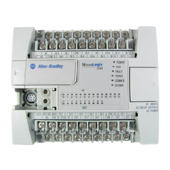
Chapter Hardware Overview Hardware Features The Bulletin 1762, MicroLogix 1200 programmable controller contains a power supply, input and output circuits, and a processor. The controller is available in 24 I/O and 40 I/O configurations. The hardware features of the controller are:... -
Page 12: Component Descriptions
(4) fast 24V dc (1) high-speed 24V dc FET Component Descriptions MicroLogix 1200 Memory Module and/or Real-Time Clock The controller is shipped with a memory module port cover in place. You can order a memory module, real-time clock, or memory module and real-time clock as an accessory. -
Page 13: 1762 Expansion I/O
Hardware Overview 1762 Expansion I/O 1762 expansion I/O can be connected to the MicroLogix 1200 controller, as shown below. A maximum of six I/O modules, in certain combinations, may be connected to a controller. See Appendix F System Loading and Heat Dissipation to determine valid combinations. -
Page 14: Communication Cables
RSLogix™ 500, Revision 4 or later. You must use Revision 4.5 or later of RSLogix™ 500 in order to use the new features of the Series B MicroLogix 1200 controllers, including the full ASCII instruction set. Communication cables for programming are not included with the software. - Page 15 FRN4 ControlFlash upgrade, and is a functional equivalent) or higher ControlFlash tool. For users of RSLogix 500 Programming Software version 4.5 - MicroLogix 1200 Series C Revision B controllers with FRN5 or later firmware may be downgraded for compatibility with this version of software using the ControlFlash FRN 3.1 tool available on the MicroLogix website. Your controller may be later upgraded using the FRN5 (which replaces the FRN 4 ControlFlash upgrade, and is a functional equivalent) or higher ControlFlash tool.
-
Page 16: Communication Options
Hardware Overview Communication Options The MicroLogix 1200 can be connected to a personal computer. It can also be connected to a DH-485 network, or a Modbus™ network as an RTU Master or RTU Slave using an Advanced Interface Converter (catalog number 1761-NET-AIC) and to the DeviceNet™ network using a DeviceNet Interface (catalog number 1761-NET-DNI). -
Page 17: Installing Your Controller
Chapter Installing Your Controller This chapter shows you how to install your controller. The only tools you require are a flat or Phillips head screwdriver and drill. Topics include: • agency certifications • compliance to European Union Directives • installation considerations •... -
Page 18: Emc Directive
Programmable Controllers, Part 2 - Equipment Requirements and Tests. For specific information required by EN 61131-2, see the appropriate sections in this publication, as well as the following Allen-Bradley publications: • Industrial Automation Wiring and Grounding Guidelines for Noise Immunity, publication 1770-4.1 •... -
Page 19: Safety Considerations
Installing Your Controller Vertical mounting of the controller is not ATTENTION recommended due to heat build-up considerations. Be careful of metal chips when drilling mounting ATTENTION holes for your controller or other equipment within the enclosure or panel. Drilled fragments that fall into the controller or I/O modules could cause damage. -
Page 20: Disconnecting Main Power
Installing Your Controller Use only the following communication cables in Class I, Division 2 hazardous locations. Communication Cables for Class I, Division 2 Hazardous Locations 1761-CBL-PM02 Series C or later 1761-CBL-HM02 Series C or later 1761-CBL-AM00 Series C or later 1761-CBL-AP00 Series C or later 2707-NC8 Series A or later 2707-NC9 Series B or later... -
Page 21: Power Distribution
Installing Your Controller Power Distribution There are some points about power distribution that you should know: • The master control relay must be able to inhibit all machine motion by removing power to the machine I/O devices when the relay is de-energized. It is recommended that the controller remain powered even when the master control relay is de-energized. -
Page 22: Power Supply Inrush
Installing Your Controller Power Supply Inrush During power-up, the MicroLogix 1200 power supply allows a brief inrush current to charge internal capacitors. Many power lines and control transformers can supply inrush current for a brief time. If the power source cannot supply this inrush current, the source voltage may sag momentarily. -
Page 23: Input States On Power Down
Installing Your Controller Input States on Power Down The power supply hold-up time as described above is generally longer than the turn-on and turn-off times of the inputs. Because of this, the input state change from “On” to “Off” that occurs when power is removed may be recorded by the processor before the power supply shuts down the system. -
Page 24: Master Control Relay
Installing Your Controller Master Control Relay A hard-wired master control relay (MCR) provides a reliable means for emergency machine shutdown. Since the master control relay allows the placement of several emergency-stop switches in different locations, its installation is important from a safety standpoint. Overtravel limit switches or mushroom-head push buttons are wired in series so that when any of them opens, the master control relay is de-energized. -
Page 25: Using Emergency-Stop Switches
Installing Your Controller Do not control the master control relay with the controller. Provide the operator with the safety of a direct connection between an emergency-stop switch and the master control relay. Using Emergency-Stop Switches When using emergency-stop switches, adhere to the following points: •... -
Page 26: Schematic (Using Iec Symbols)
2-10 Installing Your Controller Schematic (Using IEC Symbols) 230V ac Disconnect Fuse 230V ac Circuits Isolation Operation of either of these contacts will Transformer remove power from the external I/O Master Control Relay (MCR) circuits, stopping machine motion. 115V ac Cat. -
Page 27: Schematic (Using Ansi/Csa Symbols)
Installing Your Controller 2-11 Schematic (Using ANSI/CSA Symbols) 230V ac Disconnect Fuse 230V ac Output Circuits Isolation Operation of either of these contacts will Transformer remove power from the external I/O Master Control Relay (MCR) circuits, stopping machine motion. 115V ac or Cat. -
Page 28: Installing A Memory Module And/Or Real-Time Clock
2-12 Installing Your Controller Installing a Memory 1. Remove the memory module port cover. Module and/or Real-Time Clock 2. Align the connector on the memory module with the connector pins on the controller. 3. Firmly seat the memory module into the controller. Publication 1762-UM001D-EN-P - March 2004... -
Page 29: Controller Mounting Dimensions
Installing Your Controller 2-13 Controller Mounting Dimensions 1762-L40AWA, 1762-L40BWA, 1762-L40BXB 1762-L24AWA, 1762-L24BWA, 1762-L24BXB 1762-L40AWAR, 1762-L40BWAR, 1762-L40BXBR 1762-L24AWAR, 1762-L24BWAR, 1762-L24BXBR Table 2.1 Controller Dimensions Dimension 1762-L24AWA 1762-L24BWA 1762-L24BXB 1762-L40AWA 1762-L40BWA 1762-L40BXB 1762-L24AWAR 1762-L24BWAR 1762-L24BXBR 1762-L40AWAR 1762-L40BWAR 1762-L40BXBR 90 mm (3.5 in.) 90 mm (3.5 in.) 110 mm (4.33 in.) 160 mm (6.30 in.) -
Page 30: Mounting The Controller
2-14 Installing Your Controller Mounting the Controller MicroLogix™ 1200 controllers are suitable for use in an industrial environment when installed in accordance with these instructions. Specifically, this equipment is intended for use in clean, dry environments (Pollution degree 2 ) and to circuits not exceeding Over Voltage Category II (IEC 60664-1). -
Page 31: Din Rail Mounting
Installing Your Controller 2-15 DIN Rail Mounting The maximum extension of the latch is 14 mm (0.55 in.) in the open position. A flat-blade screwdriver is required for removal of the controller. The controller can be mounted to EN50022-35x7.5 or EN50022-35x15 DIN rails. -
Page 32: Panel Mounting
Mount to panel using #8 or M4 screws. To install your controller using mounting screws: 1. Remove the mounting template from inside the back cover of the MicroLogix 1200 Programmable Controllers Installation Instructions, publication 1762-IN006. 2. Secure the template to the mounting surface. (Make sure your controller is spaced properly. -
Page 33: 1762 Expansion I/O Dimensions
Installing Your Controller 2-17 1762 Expansion I/O Dimensions Dimension Expansion I/O Module 90 mm (3.5 in.) 40 mm (1.57 in.) 87 mm (3.43 in.) Mounting 1762 During panel or DIN rail mounting of all devices, be Expansion I/O ATTENTION sure that all debris (metal chips, wire stands, etc.) is kept from falling into the module. -
Page 34: Panel Mounting
2-18 Installing Your Controller Use DIN rail end anchors (Allen-Bradley part number 1492-EA35 or 1492-EAH35) for vibration or shock environments. The following illustration shows the location of the end anchors. End Anchor End Anchor 1762 expansion I/O must be mounted horizontally as illustrated. -
Page 35: Connecting Expansion I/O
Installing Your Controller 2-19 Connecting Expansion I/O The expansion I/O module is attached to the controller or another I/O module by means of a flat ribbon cable after mounting, as shown below. Pull Loop Use the pull loop on the connector to disconnect modules. - Page 36 2-20 Installing Your Controller EXPLOSION HAZARD WARNING In Class I, Division 2 applications, the bus connector must be fully seated and the bus connector cover must be snapped in place. In Class I, Division 2 applications, all modules must be mounted in direct contact with each other as shown on page 2-19.
-
Page 37: Wiring Requirements
Chapter Wiring Your Controller This chapter describes how to wire your controller and expansion I/O. Topics include: • wire requirements • using surge suppressors • grounding the controller • wiring diagrams • sinking and sourcing wiring diagrams • controller I/O wiring •... - Page 38 Wiring with Spade Lugs The diameter of the terminal screw head is 5.5 mm (0.220 in.). The input and output terminals of the MicroLogix 1200 controller are designed for a 6.35mm (0.25 in.) wide spade (standard for #6 screw for up to 14 AWG) or a 4 mm (metric #4) fork terminal.
-
Page 39: Using Surge Suppressors
Wiring Your Controller When using spade lugs, use a small, flat-blade screwdriver to pry the finger-safe cover from the terminal blocks as shown below. Then loosen the terminal screw. Using Surge Suppressors Because of the potentially high current surges that occur when switching inductive load devices, such as motor starters and solenoids, the use of some type of surge suppression to protect and extend the operating life of the controllers output contacts is required. - Page 40 Suitable surge suppression methods for inductive ac load devices include a varistor, an RC network, or an Allen-Bradley surge suppressor, all shown below. These components must be appropriately rated to suppress the switching transient characteristic of the particular inductive device.
-
Page 41: Recommended Surge Suppressors
Wiring Your Controller Recommended Surge Suppressors Use the Allen-Bradley surge suppressors shown in the following table for use with relays, contactors, and starters. Table 3.2 Recommended Surge Suppressors Device Coil Voltage Suppressor Catalog Number Bulletin 509 Motor Starter 120V ac... - Page 42 Wiring Your Controller All devices connected to the RS-232 channel must be referenced to controller ground, or ATTENTION be floating (not referenced to a potential other than ground). Failure to follow this procedure may result in property damage or personal injury. •...
-
Page 43: Wiring Diagrams
Wiring Diagrams The following illustrations show the wiring diagrams for the MicroLogix 1200 controllers. Controllers with dc inputs can be wired as either sinking or sourcing inputs. (Sinking and sourcing does not apply to ac inputs.) Refer to Sinking and Sourcing Wiring Diagrams on page 3-10 The controller terminal block layouts are shown below. - Page 44 Wiring Your Controller Figure 3.2 1762-L24BWA and 1762-L24BWAR Group 0 Group 1 IN 0 IN 2 IN 5 IN 7 IN 9 IN 11 IN 13 Inputs IN 1 IN 3 IN 4 IN 6 IN 8 IN 10 IN 12 OUT 0 OUT 1 OUT 2...
-
Page 45: Terminal Groupings
Wiring Your Controller Figure 3.5 1762-L40BWA and 1762-L40BWAR Group 0 Group 1 Group 2 IN 0 IN 2 IN 5 IN 7 IN 8 IN 10 IN 12 IN 14 IN 16 IN 18 IN 20 IN 22 Inputs IN 1 IN 3 IN 4 IN 6... -
Page 46: Sinking And Sourcing Wiring Diagrams
Group 4 VAC/VDC 4 O/12 through O/15 Sinking and Sourcing Any of the MicroLogix 1200 DC embedded input groups can be configured as sinking or sourcing depending on how the DC COM is Wiring Diagrams Publication 1762-UM001D-EN-P - March 2004... -
Page 47: 1762-L24Awa, 1762-L24Bwa, 1762-L24Bxb, 1762-L24Awar, 1762-L24Bwar And 1762-L24Bxbr Wiring Diagrams
Wiring Your Controller 3-11 wired on the group. Refer to pages 3-12 through 3-16 for sinking and sourcing wiring diagrams. Type Definition Sinking Input The input energizes when high-level voltage is applied to the input terminal (active high). Connect the power supply VDC (-) to the input group’s COM terminal. - Page 48 3-12 Wiring Your Controller Figure 3.8 1762-L24BWA and 1762-L24BWAR Sinking Input Wiring Diagram -DCb +DCa +DCb IN 0 IN 2 IN 5 IN 7 IN 9 IN 11 IN 13 COM 1 IN 1 IN 3 IN 4 IN 6 IN 8 IN 10 IN 12...
- Page 49 Wiring Your Controller 3-13 Figure 3.10 1762-L24BXB and 1762-L24BXBR Sinking Input Wiring Diagram -DCb +DCa +DCb IN 0 IN 2 COM 1 IN 5 IN 7 IN 9 IN 11 IN 13 USED IN 1 IN 3 IN 4 IN 6 IN 8 IN 10 IN 12...
- Page 50 3-14 Wiring Your Controller Figure 3.12 1762-L24AWA , 1762-L24BWA, 1762-L24AWAR, and 1762-L24BWAR Output Wiring Diagram -DCa OUT 0 OUT 1 OUT 2 OUT 5 OUT 6 OUT 8 DC 3 NEUT OUT 3 OUT 4 OUT 7 OUT 9 DC 0 DC 1 DC 2 DC 4...
-
Page 51: 1762-L40Awa, 1762-L40Bwa, 1762-L40Bxb , 1762-L40Awar, 1762-L40Bwar And 1762-L40Bxbr Wiring Diagrams
Wiring Your Controller 3-15 1762-L40AWA, 1762-L40BWA, 1762-L40BXB , 1762-L40AWAR, 1762-L40BWAR and 1762-L40BXBR Wiring Diagrams Figure 3.14 1762-L40AWA and 1762-L40AWAR Input Wiring Diagram IN 0 IN 2 IN 5 IN 7 IN 8 IN 10 IN 12 IN 14 IN 16 IN 18 IN 20 IN 22 IN 1 IN 3 IN 4... - Page 52 3-16 Wiring Your Controller Figure 3.17 1762-L40BXB and 1762-L40BXBR Sinking Input Wiring Diagram -DCb +DCb +DCa +DCc IN 0 IN 2 IN 5 IN 7 IN 8 IN 10 IN 12 IN 14 IN 16 IN 18 IN 20 IN 22 USED IN 1 IN 3...
-
Page 53: Controller I/O Wiring
To help reduce the effects of environmental noise, install the MicroLogix 1200 system in a properly rated (i.e. NEMA) enclosure. Make sure that the MicroLogix 1200 system is properly grounded. - Page 54 3-18 Wiring Your Controller Figure 3.21 1762-IA8 Wiring Diagram IN 0 IN 1 IN 2 IN 3 100/120V ac IN 4 IN 5 IN 6 IN 7 Common connected internally. Figure 3.22 1762-IQ8 Wiring Diagram +DC (sinking) IN 0 IN 1 IN 2 IN 3 24V dc...
- Page 55 Wiring Your Controller 3-19 Figure 3.23 1762-IQ16 Wiring Diagram +DC (Sinking) -DC (Sourcing) IN 0 IN 1 IN 2 IN 3 24V dc IN 4 IN 5 IN 6 IN 7 -DC (Sinking) COM 0 +DC (Sourcing) +DC (Sinking) -DC (Sourcing) IN 8 IN 9 IN 10...
- Page 56 3-20 Wiring Your Controller Figure 3.25 1762-OB8 Wiring Diagram +VDC OUT 0 OUT 1 OUT 2 OUT 3 OUT 4 OUT 5 24V dc (source) OUT 6 OUT 7 DC COM Figure 3.26 1762-OB16 Wiring Diagram VDC+ OUT 0 OUT 1 OUT 2 OUT 3 OUT 4...
- Page 57 Wiring Your Controller 3-21 Figure 3.27 1762-OW8 Wiring Diagram L1 VAC1 + VAC-VDC 1 OUT 0 L2 DC1 COM OUT 1 OUT 2 OUT3 L1 VAC2 + VAC-VDC2 OUT 4 L2 DC2 COM OUT 5 OUT 6 OUT 7 Figure 3.28 1762-OW16 Wiring Diagram VAC-VDC OUT 0 OUT 1...
-
Page 58: Analog Wiring
3-22 Wiring Your Controller Figure 3.29 1762-OX6I Wiring Diagram L1-0 L1 OR +DC OUT0 N.C. OUT0 N.O. L2 OR -DC L1 OR +DC L1-1 OUT1 N.C. OUT1 N.O. L2 OR -DC L1-2 L1 OR +DC OUT2 N.C. L2 OR -DC OUT2 N.O. - Page 59 The output type selection, current or voltage, is made by wiring to the appropriate terminals, Iout or Vout, and by the type/range selection bits in the Configuration Data File. Refer to MicroLogix 1200 and 1500 Programmable Controllers Instruction Set Reference Manual, publication number 1762-RM001.
- Page 60 3-24 Wiring Your Controller 1762-IF2OF2 Wiring The following illustration shows the 1762-IF2OF2 analog expansion I/O terminal block. Figure 3.30 1762-IF2OF2 Terminal Block Layout IN 0 (+) IN 0 (-) IN 1 (+) IN 1 (-) V Out 0 I Out 0 V Out 1 I Out 1 Common connected...
- Page 61 Select the input type, current or voltage, using the switches located on the module’s circuit board and the input type/range selection bits in the Configuration Data File. Refer to MicroLogix 1200 and 1500 Programmable Controllers Instruction Set Reference Manual, publication number 1762-RM001. You can access the switches through the ventilation slots on the top of the module.
- Page 62 3-26 Wiring Your Controller Figure 3.33 1762-IF4 Terminal Block Layout IN 0 (+) IN 0 (-) IN 1 (+) IN 1 (-) IN 2 (+) IN 2 (-) IN 3 (+) IN 3 (-) Commons internally connected. Figure 3.34 Differential Sensor Transmitter Types IN 0 (+) Analog Sensor IN 0 (-)
- Page 63 Wiring Your Controller 3-27 Figure 3.35 Sensor/Transmitter Types 2-Wire Transmitter Transmitter Module Power IN + Supply IN - Transmitter 3-Wire Transmitter Module Supply Signal IN + Power IN - Supply 4-Wire Transmitter Transmitter Module Signal Supply IN + Power IN - Supply (1) All power supplies rated N.E.C.
- Page 64 3-28 Wiring Your Controller 1762-OF4 Wiring I out 0 Current Load I out 1 I out 2 I out 3 V out 0 Voltage Load V out 1 V out 2 V out 3 Publication 1762-UM001D-EN-P - March 2004...
-
Page 65: Supported Communication Protocols
• connecting to RS-232 port • connecting to DH-485 network • connecting to AIC+ • DeviceNet communications MicroLogix 1200 controllers with the additional communications port (1762-L24AWAR, 1762-L24BWAR, 1762-L24BXBR, 1762-L40AWAR, 1762-L40BWAR, 1762-L40BXBR) offer advanced communications options, providing a clean, cost effective solution for applications requiring a network connection and HMI. -
Page 66: Default Communication Configuration
All communication parameters are fixed and cannot be changed by a user. See Default Communication Configuration on page 4-2 for the configuration settings. For more information on MicroLogix 1200 communications, refer to the MicroLogix 1200 and MicroLogix 1500 Programmable Controllers Instruction Set Reference Manual, publication number 1762-RM001. - Page 67 Communication Connections Use the Communications Toggle Push Button to change from the user-defined communication configuration to the default communications mode and back on Channel 0. The parameters of the Programmer/HMI Port are fixed at the default communications configuration. The Default Communications (DCOMM) LED operates to show when the controller is in the default communications mode (settings shown on page 4-2).
-
Page 68: Connecting To The Rs-232 Port
Communication Connections Connecting to the RS-232 There are two ways to connect the MicroLogix 1200 programmable controller to your personal computer using the DF1 protocol: using a Port point-to-point connection, or using a modem. Descriptions of these methods follow. All devices connected to the RS-232 channel must be... -
Page 69: Making A Df1 Point-To-Point Connection
Communication Connections Making a DF1 Point-to-Point Connection You can connect the MicroLogix 1200 programmable controller to your personal computer using a serial cable (1761-CBL-PM02) from your personal computer’s serial port to the controller via Channel 0 and/or the Programmer/HMI Port (for 1762-LxxxxxR only). The recommended protocol for this configuration is DF1 Full-Duplex. -
Page 70: Isolated Modem Connection
Isolated Modem Connection Using an AIC+ to isolate the modem is illustrated below. 24V dc MicroLogix 1200 MicroLogix 1200 provides power to the AIC+ or an external power Channel 0 supply may be used. See Appendix F, System Loading and Heat Dissipation. - Page 71 Communication Connections Constructing Your Own Modem Cable If you construct your own modem cable, the maximum cable length is 15.24 m (50 ft) with a 25-pin or 9-pin connector. Refer to the following typical pinout for constructing a straight-through cable: DTE Device DCE Device (AIC+,...
-
Page 72: Connecting To A Df1 Half-Duplex Network
Communication Connections Connecting to a DF1 Half-Duplex Network Use the following diagram for DF1 Half-Duplex Master-Slave protocol without hardware handshaking. SLC 5/03 MicroLogix 1200 processor Master 1761-CBL-AM00 or 1761-CBL-HM02 1761-CBL-AP00 or 1761-CBL-PM02 DF1 Slave radio modem or lease line AIC+... -
Page 73: Recommended Tools
Communication Connections Connecting to a DH-485 The following illustration shows how to connect to a DH-485 network. Network MicroLogix DH-485 Network MicroLogix 1200 connection from port 1 or port 2 to MicroLogix Channel 0 1761-CBL-AM00 PC to port 1 or 1761-CBL-HM02... -
Page 74: Connecting The Communication Cable To The Dh-485 Connector
Use these instructions for wiring the Belden #3106A or #9842 cable. (See Cable Selection Guide on page 4-14 if you are using standard Allen-Bradley cables.) Connecting the Communication Cable to the DH-485 Connector A daisy-chained network is recommended. Do not... - Page 75 Communication Connections 4-11 6 Termination Orange with White Stripes White with Orange Stripes 3 Common 2 Shield 1 Chassis Ground Blue (#3106A) or Shrink Tubing Recommended Drain Wire Blue with White Stripes (#9842) Multiple Cable Connection When connecting multiple cables to the DH-485 connector, use the following diagram.
-
Page 76: Grounding And Terminating The Dh-485 Network
1219 m (4000ft) Maximum Jumper Connecting the AIC+ The AIC+, catalog number 1761-NET-AIC, enables a MicroLogix 1200 to connect to a DH-485 network. The AIC+ has two RS-232 ports and one isolated RS-485 port. Typically, there is one AIC+ for each MicroLogix 1200. - Page 77 Communication Connections 4-13 The following figure shows the external wiring connections and specifications of the AIC+. AIC+ Advanced Interface Converter (1761-NET-AIC) Publication 1762-UM001D-EN-P - March 2004...
-
Page 78: Cable Selection Guide
4-14 Communication Connections Item Description Port 1 - DB-9 RS-232, DTE Port 2 - mini-DIN 8 RS-232 DTE Port 3 - RS-485 Phoenix plug DC Power Source selector switch (cable = port 2 power source, external = external power source connected to item 5) Terminals for external 24V dc power supply and chassis ground For additional information on connecting the AIC+, refer to the Advanced Interface Converter (AIC+) User Manual, publication... - Page 79 Communication Connections 4-15 Series C or higher cables are required. 1747-CP3 1761-CBL-AC00 Cable Length Connections from to AIC+ External Power Power Supply Selection Switch Required Setting 1747-CP3 3m (9.8 ft) SLC 5/03 or SLC 5/04 processor, channel port 1 external 45 cm (17.7 in) 1761-CBL-AC00 PC COM port...
-
Page 80: Recommended User-Supplied Components
4-16 Communication Connections 1761-CBL-PM02 Series C (or equivalent) Cable Wiring Diagram Programming Controller Device 9-Pin D-Shell 8-Pin Mini Din Recommended User-Supplied Components These components can be purchased from your local electronics supplier. Table 4.6 User Supplied Components Component Recommended Model external power supply and chassis ground power supply rated for 20.4 to 28.8V dc NULL modem adapter... -
Page 81: Safety Considerations
If you are making a cable to connect to port 2, you must configure your cable to connect to the Allen-Bradley cable shown above. In the 1761-CBL-PM02 cable, pins 4 and 6 are jumpered together within the DB-9 connector. -
Page 82: Installing And Attaching The Aic
Installing and Attaching the AIC+ 1. Take care when installing the AIC+ in an enclosure so that the cable connecting the MicroLogix 1200 controller to the AIC+ does not interfere with the enclosure door. 2. Carefully plug the terminal block into the RS-485 port on the AIC+ you are putting on the network. - Page 83 Communication Connections 4-19 Always connect the CHS GND (chassis ground) ATTENTION terminal to the nearest earth ground. This connection must be made whether or not an external 24V dc supply is used. Power Options Below are two options for powering the AIC+: •...
-
Page 84: Devicenet Communications
4-20 Communication Connections DeviceNet Communications You can connect a MicroLogix 1200 to a DeviceNet network using the DeviceNet Interface (DNI), catalog number 1761-NET-DNI. For additional information on using the DNI, refer to the DeviceNet Interface User Manual, publication 1761-6.5. The following figure shows the external wiring connections of the DNI. -
Page 85: Chapter 5 Trim Pot Operation
Chapter Using Trim Pots Trim Pot Operation The processor has two trimming potentiometers (trim pots) which allow modification of data within the controller. Adjustments to the trim pots change the value in the corresponding Trim Pot Information (TPI) register. The data value of each trim pot can be used throughout the control program as timer, counter, or analog presets depending upon the requirements of the application. -
Page 86: Trim Pot Information Function File
Using Trim Pots Trim Pot Information Function File The composition of the Trim Pot Information (TPI) Function File is described in the MicroLogix 1200 and 1500 Programmable Controllers Instruction Set Reference Manual, publication 1762-RM001. Error Conditions Error conditions of the TPI Function File are described in the MicroLogix 1200 and 1500 Programmable Controllers Instruction Set Reference Manual, publication 1762-RM001. -
Page 87: Real-Time Clock Operation
If an RTC is installed while the MicroLogix 1200 is in a run or test mode, the module is not recognized until either a power cycle occurs or until the controller is placed in a non-executing mode (program mode, suspend mode or fault condition). -
Page 88: Writing Data To The Real-Time Clock
Using Real-Time Clock and Memory Modules Table 6.1 RTC Accuracy Ambient Temperature Accuracy 0°C (+32°F) +34 to -70 seconds/month +25°C (+77°F) +36 to -68 seconds/month +40°C (+104°F) +29 to -75 seconds/month +55°C (+131°F) -133 to -237 seconds/month These numbers are maximum worst case values over a 31-day month. Writing Data to the Real-Time Clock When valid data is sent to the real-time clock from the programming device or another controller, the new values take effect immediately. -
Page 89: Memory Module Operation
Using Real-Time Clock and Memory Modules Operating with a low battery indication for more ATTENTION than 14 days may result in invalid RTC data unless power is on continuously. Memory Module Operation The memory module supports the following features: • User Program and Data Back-up •... -
Page 90: Program Compare
The memory module can be installed or removed at any time without risk of damage to either the memory module or the controller. If a memory module is installed while the MicroLogix 1200 is executing, the memory module is not recognized until either a power cycle occurs, or until the controller is placed in a non-executing mode (program mode, suspend mode or fault condition). -
Page 91: Controller Specifications
Appendix Specifications Controller Specifications Table A.1 General Specifications Description 1762- L24AWA L24BWA L24BXB L40AWA L40BWA L40BXB L24AWAR L24BWAR L24BXBR L40AWAR L40BWAR L40BXBR Dimensions Height: 90 mm, Height: 90 mm 104 mm (with DIN latch open) 104 mm (with DIN latch open) Width: 110 mm, Depth: 87 mm Width: 160 mm, Depth: 87 mm Shipping Weight... - Page 92 Specifications Table A.1 General Specifications Description 1762- L24AWA L24BWA L24BXB L40AWA L40BWA L40BXB L24AWAR L24BWAR L24BXBR L40AWAR L40BWAR L40BXBR • UL 508 Agency Certification • C-UL under CSA C22.2 no. 142 • Class I, Div. 2, Groups A, B, C, D (UL 1604, C-UL under CSA C22.2 no.
- Page 93 Specifications Table A.3 Output Specifications - General Description 1762- L24AWA L24BXB L40AWA L40BXB L24BWA L24BXBR L40BWA L40BXBR L24AWAR L40AWAR L24BWAR L40BWAR Relay and FET Outputs Maximum Controlled Load 1440 VA – 1440 VA 1440 VA Maximum Continuous Current: Current per Group Common 7.5A Current per Controller at 150V max...
- Page 94 Specifications Table A.4 BXB FET Output Specifications Description General Operation High Speed Operation (Output 2 Only) Surge Current per Point: • peak current • 4.0A • Not Applicable • maximum surge duration • 10 msec • Not Applicable • maximum rate of repetition at 30°C (86°F) •...
- Page 95 Specifications Table A.7 Normal DC Input Filter Settings (Inputs 4 and higher) Nominal Filter Setting (ms) ON Delay (ms) OFF Delay (ms) Maximum Frequency (Hz) 50% Duty Cycle Minimum Maximum Minimum Maximum 0.500 0.090 0.500 0.020 0.500 1.0 kHz 1.000 0.500 1.000 0.400...
-
Page 96: Expansion I/O Specifications
Specifications Table A.10 Working Voltage (1762-L24BWA, 1762-L40BWA, 1762-L24BWAR, 1762-L40BWAR) Description 1762-L24BWA, 1762-L40BWA, 1762-L24BWAR, 1762-L40BWAR Power Supply Input to Backplane Isolation Verified by one of the following dielectric tests:1836V ac for 1 second or 2596V dc for 1 second 265V ac Working Voltage (IEC Class 2 reinforced insulation) Input Group to Backplane Isolation and Verified by one of the following dielectric tests: 1200V ac for 1 second or 1697V dc for 1 second Input Group to Input Group Isolation... - Page 97 Specifications Table A.12 General Specifications Specification Value Vibration Operating: 10 to 500 Hz, 5G, 0.030 in. max. peak-to-peak, 2 hours per axis Relay Operation: 1.5G Shock Operating: 30G panel mounted, 3 pulses per axis Relay Operation: 7G Non-Operating: 50G panel mounted, 3 pulses per axis (40G DIN Rail mounted) Agency Certification C-UL certified (under CSA C22.2 No.
- Page 98 Specifications Table A.13 Input Specifications Specification 1762-IA8 1762-IQ8 1762-IQ16 Off-State Voltage (max.) 20V ac 5V dc 5V dc Off-State Current (max.) 2.5 mA 1.5 mA 1.5 mA On-State Voltage (min.) 79V ac (min.) 132V ac (max.) 10V dc 10V dc On-State Current 5.0 mA (min.) at 79V ac 47 Hz 2.0 mA min.
- Page 99 Specifications Table A.14 Output Specifications Spec. 1762-OA8 1762-OB8 1762-OB16 1762-OW8 1762-OW16 1762-OX6I Bus Current 115 mA at 5V dc 115 mA at 5V dc 175 mA at 5V dc 80 mA at 5V dc 120 mA at 5V dc 110 mA at 5V dc Draw (max.) (0.575W) (0.575W)
- Page 100 A-10 Specifications Table A.14 Output Specifications Spec. 1762-OA8 1762-OB8 1762-OB16 1762-OW8 1762-OW16 1762-OX6I Isolated Group 1: Outputs 0 to Group 1: Outputs 0 Group 1: Outputs 0 Group 1: Group 1: All 6 Outputs Groups to 7 to 15 Outputs 0 to 3 Outputs 0 to 7 Individually Isolated.
- Page 101 Specifications A-11 Table A.16 Relay Contact Ratings 1762-OX6I Volts Continuous Voltamperes Amperes (max.) Amps per Make Break Make Break Point (max.) 240V ac 5.0 A 15 A 1.5 A 3600 VA 360 VA 120V ac 30 A 3.0 A 7.0 A 125V dc 2.5 A 0.4 A...
-
Page 102: Analog Modules
A-12 Specifications Relays Used vs. Maximum Current per Relay (24V dc) 1762-OX6I Ambient Temperature below 40°C Ambient Temperature above 40°C Number of Relays Controlling Loads Analog Modules Table A.18 Common Specifications Specification 1762-IF2OF2, 1762-IF4, 1762-IR4, 1762-IT4 and 1762-OF4 Dimensions 90 mm (height) x 87 mm (depth) x 40 mm (width) height including mounting tabs is 110 mm 3.54 in. - Page 103 Specifications A-13 Table A.18 Common Specifications Specification 1762-IF2OF2, 1762-IF4, 1762-IR4, 1762-IT4 and 1762-OF4 ESD Immunity (IEC1000-4-2) 4 kV contact, 8 kV air, 4 kV indirect Radiated Immunity (IEC1000-4-3) 10 V/m, 80 to 1000 MHz, 80% amplitude modulation, +900 MHz keyed carrier Fast Transient Burst (IEC1000-4-4) 2 kV, 5 kHz Surge Immunity (IEC1000-4-5)
- Page 104 A-14 Specifications Table A.19 General Specifications Specification 1762-IF2OF2 1762-IF4 1762-OF4 1762-IR4 1762-IT4 Vendor I.D. Code Product Type Code Product Code (1) The over- or under-range flag comes on when the normal operating range (over/under) is exceeded. The module continues to convert the analog input up to the maximum full scale range.
- Page 105 Specifications A-15 Table A.21 Input Specifications 1762-IR4 Specification 1762-IR4 • 100Ω Platinum 385 Input Types • 200Ω Platinum 385 • 500Ω Platinum 385 • 1000Ω Platinum 385 • 100Ω Platinum 3916 • 200Ω Platinum 3916 • 500Ω Platinum 3916 • 1000Ω Platinum 3916 •...
- Page 106 A-16 Specifications (2) Open-circuit detection time is equal to channel update time. Table A.22 Input Specifications 1762-IT4 Specification Value Heat Dissipation 1.5 Total Watts (The Watts per point, plus the minimum Watts, with all points energized.) Response Speed per Channel Input filter and configuration dependent.
- Page 107 Specifications A-17 (1) (2) Table A.23 1762-IT4 Repeatability at 25°C (77°F) Input Type Repeatability for 10 Hz Filter Thermocouple J ±0.1°C [±0.18°F] Thermocouple N (-110°C to +1300°C [-166°F to +2372°F]) ±0.1°C [±0.18°F] Thermocouple N (-210°C to -110°C [-346°F to -166°F]) ±0.25°C [±0.45°F] Thermocouple T (-170°C to +400°C [-274°F to +752°F]) ±0 .1°C [±0.18°F]...
- Page 108 A-18 Specifications Table A.24 1762-IT4 Accuracy With Autocalibration Enabled Without Autocalibration (2) (3) Accuracy for 10 Hz, 50 Hz and 60 Maximum Temperature Drift Hz Filters (max.) Input Type at 25°C [77°F] at 0 to 60°C at 0 to 60°C [32 to 140°F] Ambient [32 to 140°F] Ambient...
- Page 109 Specifications A-19 Table A.25 Output Specifications Specification 1762-IF2OF2 1762-OF4 Non-linearity (in percent full scale) < ±0.5% < ±0.5% Open and Short-Circuit Protection Continuous Continuous Output Protection ±32 mA ±32 mA (1) Includes offset, gain, non-linearity and repeatability error terms. Table A.26 Valid Input/Output Data Word Formats/Ranges for 1762-IF2OF2 Normal Operating Range Full Scale Range RAW/Proportional Data...
- Page 110 A-20 Specifications Publication 1762-UM001D-EN-P - March 2004...
-
Page 111: Micrologix 1200 Replacement Kits
Appendix Replacement Parts MicroLogix 1200 Controller 40-Point Replacement Terminal Blocks Replacement Kits Catalog Number 1762-RPLRTB40 The 40-point controller removable terminal blocks kit consists of: • one 25-point double row terminal block • one 29-point double row terminal block (Both terminal blocks for a 40-point controller.) -
Page 112: 1762 Expansion I/O
Replacement Parts 1762 Expansion I/O Expansion I/O Replacement Doors Catalog Number 1762-RPLDR2 The expansion I/O door kit consists of: • Two expansion I/O terminal doors • Two expansion I/O (bus doors) Expansion I/O Replacement DIN Latches Catalog Number 1762-RPLDIN2 The expansion I/O DIN latch kit consists of: •... -
Page 113: Understanding The Controller Led Status
Appendix Troubleshooting Your System This chapter describes how to troubleshoot your controller. Topics include: • understanding the controller LED status • controller error recovery model • analog expansion I/O diagnostics and troubleshooting • calling Rockwell Automation for assistance Understanding the The controller status LEDs provide a mechanism to determine the current status of the controller if a programming device is not present Controller LED Status... -
Page 114: Normal Operation
Loose Wiring Verify connections to the controller. solid Power LED Application fault Hardware/Software For error codes and Status File information, see MicroLogix 1200 and 1500 on and Major Fault Detected Programmable Controllers Instruction Set Reference Manual, Publication FAULT LED 1762-RM001. -
Page 115: Controller Error Recovery Model
Troubleshooting Your System Controller Error Recovery Use the following error recovery model to help you diagnose software and hardware problems in the micro controller. The model provides Model common questions you might ask to help troubleshoot your system. Refer to the recommended pages within the model for further help. Identify the error code and Is the error Start... -
Page 116: Analog Expansion I/O Diagnostics And Troubleshooting
Module hardware errors are reported in the controller’s I/O status file. Refer to the MicroLogix 1200 and 1500 Programmable Controllers Instruction Set Reference Manual, publication 1762-RM001 for more information. When a fault condition is detected, the analog outputs are reset to zero. -
Page 117: Critical And Non-Critical Errors
Troubleshooting Your System Critical and Non-Critical Errors Non-critical module errors are recoverable. Channel errors (over-range or under-range errors) are non-critical. Non-critical error conditions are indicated in the module input data table. Non-critical configuration errors are indicated by the extended error code. See Table C.5 on page C-7. - Page 118 These types of module errors are typically reported in the controller’s I/O status file. Refer to the MicroLogix 1200 and 1500 Programmable Controllers Instruction Set Reference Manual, publication 1762-RM001 for more information.
-
Page 119: Error Codes
Troubleshooting Your System Error Codes Table C.5 Extended Error Codes for 1762-IF2OF2 Error Type Module Extended Error Error Description Error Code Information Code Equivalent Binary Binary No Error X000 0 0000 0000 No error General Common X200 0 0000 0000 General hardware error;... -
Page 120: Calling Rockwell Automation For Assistance
• controller type, series letter, revision letter, and firmware (FRN) number of the controller • controller LED status • controller error codes (Refer to MicroLogix 1200 and 1500 Programmable Controllers Instruction Set Reference Manual, Publication 1762-RM001 for error code information.) -
Page 121: Appendix D Preparing For Upgrade
Appendix Using Control Flash to Upgrade Your Operating System The operating system (OS) can be upgraded through the communication port on the controller. In order to download a new operating system, you must have the following: • ControlFlash™ Upgrade Kit containing the new OS Go to http://www.ab.com/micrologix to download the upgrade kit. -
Page 122: Prepare The Controller For Updating
Using Control Flash to Upgrade Your Operating System For 1762-LxxxxxR controllers, double click the 1762-LRC-FRNxx.exe file to install the operating system upgrade. Prepare the Controller for Updating Controller Configuration The controller must be configured for default communications (use communications toggle push button; DCOMM LED on) and be in the Program mode to allow the download of a new operating system. -
Page 123: Communication Interface
• DH-485 • Modbus • ASCII RS-232 Communication The communications port on the MicroLogix 1200 utilizes an RS-232 interface. RS-232 is an Electronics Industries Association (EIA) Interface standard that specifies the electrical and mechanical characteristics for serial binary communication. It provides you with a variety of system configuration possibilities. -
Page 124: Df1 Half-Duplex Protocol
MicroLogix 1200 as both a Half-Duplex programming port and a Half-Duplex peer-to-peer messaging port. MicroLogix 1200 can act as the master or as a slave on a Half-Duplex network. When the MicroLogix 1200 is a slave device, a master device is required to "run"... -
Page 125: Using Modems With Micrologix 1200 Programmable Controllers
1200 (Slave) 1500 (Slave) Module (Slave) Using Modems with MicroLogix 1200 Programmable Controllers The types of modems you can use with MicroLogix 1200 controllers include the following: • dial-up phone modems A MicroLogix 1200 controller, on the receiving end of the dial-up connection, can be configured for DF1 Full-Duplex protocol with or without handshaking. - Page 126 Half-Duplex or Full-Duplex communications, or in a multi-drop topology supporting Half-Duplex communications between three or more modems. MicroLogix 1200 also supports DF1 Radio Modem protocol. • line drivers Line drivers, also called short-haul modems, do not actually...
-
Page 127: Communication Protocol
Devices that use the DH-485 Network In addition to the MicroLogix 1200 controllers, the devices shown in the following table also support the DH-485 network. Table E.1 Allen-Bradley Devices that Support DH-485 Communication... -
Page 128: Important Dh-485 Network Planning Considerations
Connecting to Networks via RS-232 Interface Table E.1 Allen-Bradley Devices that Support DH-485 Communication Catalog Description Installation Function Publication Number 1747-DTAM, DTAM, DTAM Panel Mount Provides electronic operator interface for SLC 500 processors. 1747-6.1 2707-L8P1, Plus, and DTAM 2707-800, -L8P2, -L40P1,... - Page 129 Connecting to Networks via RS-232 Interface devices will be added in the future. The following sections help you understand and plan the network. Number of Devices and Length of Communication Cable The maximum length of the communication cable is 1219m (4000 ft). This is the total cable distance from the first node to the last node in a segment.
- Page 130 The valid range for the MicroLogix 1200 controllers is 1-31 (controllers cannot be node 0). The default setting is 1. The node address is stored in the controller Communications Status file (CS0:5/0 to CS0:5/7).
-
Page 131: Example Dh-485 Connections
Setting Controller Baud Rate The best network performance occurs at the highest baud rate, which is 19200. This is the default baud rate for a MicroLogix 1200 device on the DH-485 network. All devices must be at the same baud rate. This rate is stored in the controller Communications Status file (CS0:5/8 to CS0:5/15). - Page 132 MicroLogix 1200 MicroLogix 1500 MicroLogix Remote Packet Support MicroLogix 1200 controllers can respond and initiate with communications (or commands) that do not originate on the local DH-485 network. This is useful in installations where communication is needed between DH-485 and DH+ networks.
- Page 133 • MicroLogix 1200 controllers can respond to MSG instructions received. • The MicroLogix 1200 controllers can initiate MSG instructions to devices on the DH+ network. • PC can send read and write commands to MicroLogix 1200 controllers. • PC can do remote programming of MicroLogix 1200 controllers. AIC+...
-
Page 134: Modbus Communication Protocol
247 slave devices. MicroLogix 1200 controllers support Modbus RTU Master and Modbus RTU Slave protocol. For more information on configurating your MicroLogix 1200 controller for Modbus protocol, refer to the MicroLogix 1200 and 1500 Programmable Controllers Instruction Set Reference Manual, publication 1762-RM001. For more information about the Modbus protocol, see the Modbus Protocol Specifications (available from http://www.modbus.org). -
Page 135: System Loading Limitations
Appendix System Loading and Heat Dissipation System Loading Limitations When you connect MicroLogix accessories and expansion I/O, an electrical load is placed on the controller power supply. This section shows how to calculate the load and validate that the system will not exceed the capacity of the controller power supply. - Page 136 System Loading and Heat Dissipation Table F.2 Calculating the Current for Expansion I/O n x A n x B Catalog Number Number of Device Current Requirements Calculated Current Modules (max) at 5V dc (mA) at 24V dc (mA) at 5V dc (mA) at 24V dc (mA) 1762-IA8 1762-IF4...
-
Page 137: System Loading Worksheet
System Loading and Heat Dissipation Table F.3 Validating Systems Using 1762-L24AWA, 1762-L24BXB, 1762-L24AWAR or 1762-L24BXBR Maximum Allowable Values Calculated Values Current: Current (Subtotal 1 + Subtotal 2 from Table F.1 and Table F.2 on page F-2.): 400 mA at 5V dc 350 mA at 24V dc 0 mA + 260 mA = 260 mA at 5V dc 120 mA + 180 mA = 300 mA at 24V dc... - Page 138 System Loading and Heat Dissipation Current Loading Table F.5 Calculating the Current for MicroLogix Accessories Catalog Number Device Current Requirements Calculated Current at 5V dc (mA) at 24V dc (mA) at 5V dc (mA) at 24V dc (mA) 1761-NET-AIC when powered by the base unit communications port, selector switch in the up position Subtotal 1: (1) This is an optional accessory.
- Page 139 System Loading and Heat Dissipation Table F.7 Validating Systems using 1762-L24AWA, 1762-L24BXB, 1762-L24AWAR or 1762-L24BXBR Maximum Allowable Values Calculated Values Current: Current (Subtotal 1 from Table F.5 + Subtotal 2 from Table F.6.): 400 mA at 5V dc 350 mA at 24V dc mA at 5V dc mA at 24V dc System Loading:...
- Page 140 System Loading and Heat Dissipation Table F.10 Calculating the Current for Expansion I/O n x A n x B Catalog Number Number of Device Current Requirements (max) Calculated Current Modules at 5V dc (mA) at 24V dc (mA) at 5V dc (mA) at 24V dc (mA) 1762-IA8 1762-IF4...
-
Page 141: Current Loading
System Loading and Heat Dissipation Table F.12 Validating Systems using 1762-L40BWA or 1762-L40BWAR Maximum Allowable Values Calculated Values Current for Devices Connected to the +24V dc Sum of all current sensors Sensor Supply: 400 mA at 24V dc 150 mA at 24V dc (example sensor value) Current for MicroLogix Accessories and Current (Subtotal 1 from Table F.9 + Subtotal 2 from Table F.10): Expansion I/O:... - Page 142 System Loading and Heat Dissipation Table F.14 Calculating the Current for Expansion I/O 1762-IF4 1762-IF2OF2 1762-IQ16 1762-IR4 1762-IT4 1762-OA8 1762-OB8 1762-OB16 1762-OF4 1762-OW8 1762-OW16 1762-OX6I Total Modules (6 maximum): Subtotal 2: (1) Refer to your expansion I/O Installation Instructions for Current Requirements not listed in this table. Table F.15 Validating Systems using 1762-L40AWA, 1762-L40BXB, 1762-L40AWAR or 1762-L40BXBR Maximum Allowable Values Calculated Values...
-
Page 143: Calculating Heat Dissipation
System Loading and Heat Dissipation Table F.16 Validating Systems using 1762-L40BWA or 1762-L40BWAR = (________ mA x 24V) + (________ mA x 5V) + (________ mA x 24V) = __________ mW + __________ mW + __________ mW = __________ mW 16 Watts = __________ W Calculating Heat... - Page 144 F-10 System Loading and Heat Dissipation Publication 1762-UM001D-EN-P - March 2004...
- Page 145 Glossary The following terms are used throughout this manual. Refer to the Allen-Bradley Industrial Automation Glossary, Publication Number AG-7.1, for a complete guide to Allen-Bradley technical terms. address A character string that uniquely identifies a memory location. For example, I:1/0 is the memory address for the data located in the Input file location word1, bit 0.
- Page 146 Glossary controller A device, such as a programmable controller, used to monitor input devices and control output devices. controller overhead An internal portion of the operating cycle used for housekeeping and set-up purposes. control profile The means by which a controller determines which outputs turn on under what conditions.
- Page 147 Any run or test mode. expansion I/O Expansion I/O is I/O that is connected to the controller via a bus or cable. MicroLogix 1200 controllers use Bulletin 1762 expansion I/O. false The status of an instruction that does not provide a continuous logical path on a ladder rung.
- Page 148 Glossary high byte Bits 8 to 15 of a word. input device A device, such as a push button or a switch, that supplies signals to the input circuits of the controller. inrush current The temporary surge current produced when a device or circuit is initially energized.
- Page 149 Glossary LED (Light Emitting Diode) Used as status indicator for processor functions and inputs and outputs. LIFO (Last-In-First-Out) The order that data is entered into and retrieved from a file. low byte Bits 0 to 7 of a word. logic A process of solving complex problems through the repeated use of simple functions that can be either true or false.
- Page 150 Glossary network A series of stations (nodes) connected by some type of communication medium. A network may be made up of a single link or multiple links. nominal input current The current at nominal input voltage. normally closed Contacts on a relay or switch that are closed when the relay is de-energized or the switch is deactivated;...
- Page 151 Glossary switch should be less than the minimum operating current rating of the load that is connected to the switch. on-delay time The ON delay time is a measure of the time required for the controller logic to recognize that a signal has been presented at the input terminal of the controller.
- Page 152 Glossary program scan A part of the controller’s operating cycle. During the scan the ladder program is executed and the output data file is updated based on the program and the input data file. programming device Executable programming package used to develop ladder diagrams. protocol The packaging of information that is transmitted across a network.
- Page 153 Glossary run mode This is an executing mode during which the controller scans or executes the ladder program, monitors input devices, energizes output devices, and acts on enabled I/O forces. rung Ladder logic is comprised of a set of rungs. A rung contains input and output instructions.
- Page 154 Glossary true The status of an instruction that provides a continuous logical path on a ladder rung. upload Data is transferred to a programming or storage device from another device. watchdog timer A timer that monitors a cyclical process and is cleared at the conclusion of each cycle.
- Page 155 Index Numerics block diagrams 3-11 1762-24AWA wiring diagram Boolean operators 1762-40BWA sourcing wiring diagram branch 3-15 3-18 1762-IA8 wiring diagram 1762-IF2OF2 3-23 input type selection cables 3-23 output type selection planning routes for DH485 connections 3-24 terminal block layout 3-24 wiring 4-15 selection guide for the AIC+...
- Page 156 Index sequence of operation EMC Directive using controller encoder grounding error recovery model 3-17 I/O wiring errors installation configuration LED status critical LED status error conditions extended error information field LED status normal operation hardware 3-17 minimizing electrical noise module error field 2-14 mounting non-critical...
- Page 157 Index hard disk data file protection operation hardware errors program compare hardware features program/data backup heat dissipation removal/installation under power calculating write protection heat protection 3-17 minimizing electrical noise high byte mnemonic E-12 Modbus communication protocol modem I/O (Inputs and Outputs) modem cable input device constructing your own...
- Page 158 Index power source periodic tests of master control relay circuit loss of power distribution power supply inrush safety circuits power considerations save preparing for upgrade scan time preventing excessive heat sinking processor sinking and sourcing wiring diagrams processor file 3-10 program file sinking wiring diagram program mode...
- Page 159 Index G-10 3-13 upload 1762-L24BXB sinking 3-13 1762-L24BXB sourcing using communications toggle push 3-15 1762-L40AWA input button 3-16 1762-L40AWA output using emergency-stop switches 3-16 1762-L40BWA output using memory modules 3-15 1762-L40BWA sourcing using real-time clock 3-17 1762-L40BXB output using trim pots 3-16 1762-L40BXB sinking 3-16...
- Page 160 Index Publication 1762-UM001D-EN-P - March 2004...
-
Page 162: Rockwell Automation Support
Rockwell Automation Rockwell Automation provides technical information on the web to assist you in using our products. At http://support.rockwellautomation.com, you can Support find technical manuals, a knowledge base of FAQs, technical and application notes, sample code and links to software service packs, and a MySupport feature that you can customize to make the best use of these tools.