Omron SYSMAC C200HS Operation Manual
Programmable controllers
Hide thumbs
Also See for SYSMAC C200HS:
- Installation manual (230 pages) ,
- Operation manual (72 pages) ,
- Specification (18 pages)
Table of Contents
Advertisement
Quick Links
Advertisement
Chapters
Table of Contents

Related Manuals for Omron SYSMAC C200HS


Summary of Contents for Omron SYSMAC C200HS
- Page 1 Cat. No. W235-E1-05 SYSMAC Programmable Controllers C200HS...
- Page 2 C200HS Programmable Controllers Operation Manual Revised February 2002...
- Page 4 OMRON. No patent liability is assumed with respect to the use of the information contained herein. Moreover, because OMRON is constantly striving to improve its high-quality products, the information contained in this manual is subject to change without notice.
- Page 6 ............OMRON Product Terminology .
-
Page 7: Table Of Contents
TABLE OF CONTENTS SECTION 5 Instruction Set ........Notation . - Page 8 TABLE OF CONTENTS SECTION 10 Troubleshooting ....... . . 10-1 Alarm Indicators .
-
Page 9: Introduction
It also provides an overview of the process of programming and operating a PC and ex- plains basic terminology used with OMRON PCs. Descriptions of Peripheral Devices used with the C200HS PCs and a table of other manuals available to use with this manual for special PC applications are also provided. - Page 10 PRECAUTIONS This section provides general precautions for using the Programmable Controller (PC) and related devices. The information contained in this section is important for the safe and reliable application of the PC. You must read this section and understand the information contained before attempting to set up or operate a PC system. 1 Intended Audience .
-
Page 11: Intended Audience
It is extremely important that a PC and all PC Units be used for the specified purpose and under the specified conditions, especially in applications that can directly or indirectly affect human life. You must consult with your OMRON representative before applying a PC System to the abovementioned applications. -
Page 12: Application Precautions
Application Precautions Caution The operating environment of the PC System can have a large effect on the lon- gevity and reliability of the system. Improper operating environments can lead to malfunction, failure, and other unforeseeable problems with the PC System. Be sure that the operating environment is within the specified conditions at installa- tion and remains within the specified conditions during the life of the system. -
Page 13: Conformance To Ec Directives
Conformance to EC Directives Section 6 Conformance to EC Directives Observe the following precautions when installing the C200HS-CPU01-EC and C200HS-CPU21-EC that conform to the EC Directives. Provide reinforced insulation or double insulation for the DC power source con- nected to the DC I/O Unit and for the Power Supply Unit. Use a separate power source for the DC I/O Unit from the external power supply for the Relay Output Unit. - Page 14 It also provides an overview of the process of programming and operating a PC and explains basic terminology used with OMRON PCs. Descriptions of peripheral devices used with the C200HS, a table of other manuals available to use with this manual for special PC applications, and a description of the new features of the C200HS are also provided.
-
Page 15: Overview
The terminology used throughout this manual is somewhat different from relay terminology, but the concepts are the same. The following table shows the relationship between relay terms and the PC terms used for OMRON PCs. Relay term PC equivalent contact... -
Page 16: Pc Terminology
Appendix A Standard Models list products according to these groups. The term Unit is used to refer to all of the OMRON PC products. Although a Unit is any one of the building blocks that goes together to form a C200HS PC, its meaning is generally, but not always, limited in context to refer to the Units that are mounted to a Rack. -
Page 17: Overview Of Pc Operation
Section 1-5 Overview of PC Operation High-density I/O Units are designed to provide high-density I/O capability and include Group 2 High-density I/O Units and Special I/O High-density I/O Units. Special I/O Units are dedicated Units that are designed to meet specific needs. These include some of the High-density I/O Units, Position Control Units, High- speed Counter Units, and Analog I/O Units. -
Page 18: Peripheral Devices
PC program or to interface the PC to external devices to out- put the program or memory area data. Model numbers for all devices listed be- low are provided in Appendix A Standard Models. OMRON product names have been placed in bold when introduced in the following descriptions. -
Page 19: New C200Hs Features
Section 1-8 New C200HS Features Name Cat. No. Contents SYSMAC Support Software Operation Manuals W247/W248 Programming procedures for using the SSS Data Access Console Operation Guide W173 Data area monitoring and data modification procedures for the Data Access Console Printer Interface Unit Operation Guide W107 Procedures for interfacing a PC to a printer PROM Writer Operation Guide... -
Page 20: Improved Memory Capabilities
Section 1-8 New C200HS Features 1-8-1 Improved Memory Capabilities Internal Memory (UM) The C200HS CPUs come equipped with 16 KW of RAM in the PC itself, so a very large memory capacity is available without purchasing a separate Memory Unit. Furthermore, the Ladder Program Area has been increased to 15.2 KW. -
Page 21: Larger Instruction Set
Section 1-8 New C200HS Features I/O Refreshing Time The I/O refreshing time has been reduced for all units, as shown in the following table. I/O Unit Time Required for Refreshing !@ 3 of the C200H I/O refreshing time Standard I/O Units !@ 3 of the C200H I/O refreshing time Group-2 High-density I/O Units $@ 5 of the C200H I/O refreshing time... -
Page 22: Improved Interrupt Functions
Section 1-8 New C200HS Features TRSM(45) TRACE MEMORY SAMPLE MBS(--) SIGNED BINARY MULTIPLY MCRO(99) MACRO DBS(--) SIGNED BINARY DIVIDE MAX(--) FIND MAXIMUM FCS(--) FRAME CHECKSUM MIN(--) FIND MINIMUM 7SEG(--) 7-SEGMENT DISPLAY OUTPUT SUM(--) RXD(--) RECEIVE SRCH(--) DATA SEARCH TXD(--) TRANSMIT FPD(--) FAILURE POINT DETECTION CPS(--) -
Page 23: Built-In Rs-232C Connector
Section 1-8 New C200HS Features 1-8-7 Built-in RS-232C Connector Host link communications are possible using the RS-232C connector built into the C200HS-CPU21-E/CPU23-E/CPU31-E/CPU33-E CPU. By using the TXD and RXD instructions, RS-232C communications is possible without using time- consuming procedures. A 1-to-1 link using the LR Area or an NT link with the Programmable Terminal (PT) allows high-speed communications. -
Page 24: Using C200H Programs
Section 1-8 New C200HS Features I/O Comments Stored in PC By allocating a part of UM as the I/O Comment area, it is no longer necessary to read I/O Comments from a Peripheral Device’s floppy disk. If the Peripheral De- vice is connected to the C200HS online, the ladder diagram can be viewed with I/O comments. - Page 25 Section 1-8 New C200HS Features 7. Transfer the program and and any other require data to the C200HS. You will probably want to transfer DM data and the I/O table, if you have created an I/O table for the C200H. 8.
- Page 26 Section 1-8 New C200HS Features 10. Turn the C200HS off and then back on to reset it and transfer data from the Memory Cassette to the CPU. 11. Test program execution before attempting actual operation.
-
Page 27: Section 2 Hardware Considerations
SECTION 2 Hardware Considerations This section provides information on hardware aspects of the C200HS that are relevant to programming and software opera- tion. These include CPU Components, basic PC configuration, CPU capabilities, and Memory Cassettes. This information is covered in detail in the C200HS Installation Guide. CPU Components . -
Page 28: Cpu Components
Section 2-1 CPU Components CPU Components There are two groups of CPUs available, one that uses an AC power supply, and one that uses a DC power supply. Select one of the models shown below accord- ing to requirements of your control system. CPU model Power supply voltage C200HS-CPU01-E/CPU21-E/CPU31-E... -
Page 29: Cpu Indicators
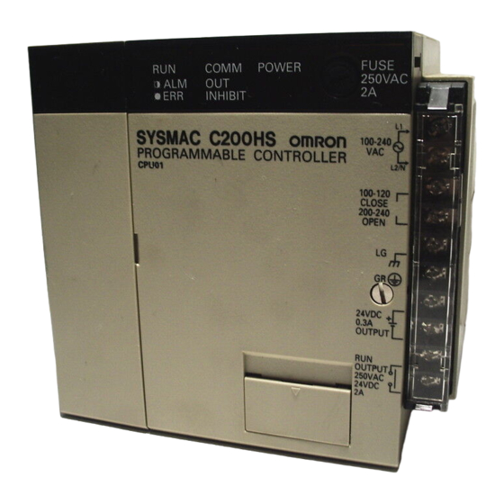
Section 2-1 CPU Components C200HS-CPU21-E/CPU23-E/CPU31-E/CPU33-E Power fuse (MF51NR, 5.2 dia. x 20 mm): C200HS-CPU21-E/CPU31-E: 2 A, 250 V Indicators C200HS-CPU23-E/CPU33-E: 5 A, 125 V Memory Casette compartment Bus connector: Available only with the CPU31-E Removable terminal block and CPU33-E. Use this connector when SYSMAC NET Link Unit or SYSMAC LINK Unit is used. -
Page 30: Peripheral Device Connection
Section 2-2 PC Configuration 2-1-2 Peripheral Device Connection A Programming Console or IBM PC/AT running LSS can be used to program and monitor the C200HS PCs. Programming Console A C200H-PR027-E or CQM1-PRO01-E Programming Console can be con- nected as shown in the following diagram. The C200H-PR027-E is connected via the C200H-CN222 or C200H-CN422 Programming Console Connecting Cable, which must be purchased separately. -
Page 31: Cpu Capabilities
Section 2-3 CPU Capabilities Expansion I/O Racks An Expansion I/O Rack can be thought of as an extension of the PC because it provides additional slots to which other Units can be mounted. It is built onto an Expansion I/O Backplane to which a Power Supply and up to ten other Units are mounted. -
Page 32: Memory Cassettes
Section 2-4 Memory Cassettes C200HS Function C200HS CPU01-E CPU21-E CPU31-E CPU03-E CPU23-E CPU33-E Built-in clock/calendar Error log Data Trace Differential Monitor Expansion DM 3K words max. General-use DM 6K words Ladder Program capacity 15.2K words max SR Area SR 236 to SR 255 and SR 256 to SR 299 New instructions: (See 1-8-3 Larger Instruction Set for a list of the 36 new instructions.) -
Page 33: Installing Memory Cassettes
Section 2-5 Installing Memory Cassettes C200HS-MPj16K (EPROM) The program is written using a PROM Writer. The ROM is mounted to the Memory Casette and then installed in the CPU. I/O data cannot be stored. Notch Installing Memory Cassettes An optional Memory Cassette can be installed in the C200HS. (The C200H Memory Unit cannot be used with the C200HS.) The two types of Memory Cas- settes are described in 2-4 Memory Cassettes. - Page 34 Section 2-5 Installing Memory Cassettes 3. Remove the bracket from the Memory Cassette, as shown in the illustration below. Metal bracket 4. Check that the connector side goes in first and that the Cassette’s circuit components face right and then insert the Cassette into the CPU. The Cas- sette slides in along a track in the CPU.
-
Page 35: Cpu Dip Switch
Section 2-6 CPU DIP Switch CPU DIP Switch The DIP switch on C200HS CPUs is located between the Memory Cassette compartment and battery. The 6 pins on the DIP switch control 6 of the CPU’s operating parameters. Pin no. Item Setting Function Memory protect... -
Page 36: Section 3 Memory Areas
SECTION 3 Memory Areas Various types of data are required to achieve effective and correct control. To facilitate managing this data, the PC is provided with various memory areas for data, each of which performs a different function. The areas generally accessible by the user for use in programming are classified as data areas. - Page 37 Section 3-1 Introduction Introduction Details, including the name, size, and range of each area are summarized in the following table. Data and memory areas are normally referred to by their acro- nyms, e.g., the IR Area, the SR Area, etc. Area Size Range...
-
Page 38: Data Area Structure
Section 3-2 Data Area Structure Work Bits and Words When some bits and words in certain data areas are not being used for their in- tended purpose, they can be used in programming as required to control other bits. Words and bits available for use in this fashion are called work words and work bits. - Page 39 Section 3-2 Data Area Structure The same TC number can be used to designate either the present value (PV) of the timer or counter, or a bit that functions as the Completion Flag for the timer or counter. This is explained in more detail in 3-8 TC Area. Area Word designation Bit designation...
- Page 40 DBS(––), DBSL(––), MBS(––), and MBSL(––)) use signed data exclusively. Unsigned binary Unsigned binary is the standard format used in OMRON PCs. Data in this manu- al are unsigned unless otherwise stated. Unsigned binary values are always positive and range from 0 ($0000) to 65,535 ($FFFF). Eight-digit values range from 0 ($0000 0000) to 4,294,967,295 ($FFFF FFFF).
- Page 41 Section 3-2 Data Area Structure The following table shows the corresponding decimal, 16-bit hexadecimal, and 32-bit hexadecimal values. Decimal 16-bit Hex 32-bit Hex 2147483647 ––– 7FFFFFFF 2147483646 ––– 7FFFFFFE 32768 ––– 00008000 32767 7FFF 00007FFF 32766 7FFE 00007FFE 0002 00000002 0001 00000001 0000...
-
Page 42: Ir (Internal Relay) Area
Section 3-3 IR Area IR (Internal Relay) Area The IR area is used both as data to control I/O points, and as work bits to manipu- late and store data internally. It is accessible both by bit and by word. In the C200HS PC, the IR area is comprised of words 000 to 235 and 298 to 511. - Page 43 Section 3-3 IR Area Allocation for Special I/O Up to ten Special I/O Units may be mounted in any slot of the CPU Rack or Ex- Units and Slave Racks pansion I/O Racks. Up to five Slave Racks may be used, whether one or two Masters are used.
-
Page 44: Sr (Special Relay) Area
Section 3-4 SR Area Allocation for Group-2 Group-2 High-density I/O Units and B7A Interface Units are allocated words be- High-density I/O Units and tween IR 030 and IR 049 according to I/O number settings made on them and do B7 Interface Units not use the words allocated to the slots in which they are mounted. - Page 45 Section 3-4 SR Area Note all SR words and bits are writeable by the user. Be sure to check the func- tion of a bit or word before attempting to use it in programming. Word(s) Bit(s) Function 00 to 07 Node loop status output area for operating level 0 of SYSMAC NET Link System 08 to 15 Node loop status output area for operating level 1 of SYSMAC NET Link System...
- Page 46 Section 3-4 SR Area Word(s) Bit(s) Function 1-minute clock pulse bit 0.02-second clock pulse bit 02 and 03 Reserved for function expansion. Do not use. Overflow Flag (for signed binary calculations) Underflow Flag (for signed binary calculations) Differential Monitor End Flag Step Flag MTR Execution Flag 7SEG Execution Flag...
- Page 47 Section 3-4 SR Area Word(s) Bit(s) Function 00 to 04 Reserved by system (not accessible by user) Host Link Level 0 Send Ready Flag 06 to 12 Reserved by system (not accessible by user) Host Link Level 1 Send Ready Flag 14 and 15 Reserved by system (not accessible by user) 00 to 15...
-
Page 48: Sysmac Net/Sysmac Link System
Section 3-4 SR Area Word(s) Bit(s) Function Save IOM to Cassette Bit Data transferred to Memory Cassette when Bit is turned ON in PROGRAM mode. Bit will automatically turn OFF. ON in PROGRAM mode. Bit will automatically turn OFF. An error will be produced if turned ON in any other Load IOM from Cassette Bit mode. - Page 49 Section 3-4 SR Area SYSMAC LINK Code Item Meaning Normal end Processing ended normally. Parameter error Parameters for network communication instruction is not within acceptable ranges. Unable to send Unit reset during command processing or local node in not in network. Destination not in Destination node is not in network.
-
Page 50: Link System Flags And Control Bits
Section 3-4 SR Area SYSMAC NET Bit (Node numbers below) Operating Operating level 0 level 1 SR 238 SR 242 SR 239 SR 243 SR 240 SR 244 SR 241 SR 245 1: PC CPU error 1: PC RUN status 3-4-2 Remote I/O Systems SR 25312 turns ON to indicate an error has occurred in Remote I/O Systems. - Page 51 Section 3-4 SR Area Host Link Systems Both Error flags and Restart bits are provided for Host Link Systems. Error flags turn ON to indicate errors in Host Link Units. Restart bits are turned ON and then OFF to restart a Host Link Unit. SR bits used with Host Link Systems are summa- rized in the following table.
-
Page 52: Forced Status Hold Bit
Section 3-4 SR Area Multilevel PC Link Systems Flag type Bit no. SR 247 SR 248 SR 249 SR 250 Run flags Unit #8, Unit #0, Unit #8, Unit #0, level 1 level 1 level 0 level 0 Unit #9, Unit #1, Unit #9, Unit #1,... -
Page 53: I/O Status Hold Bit
Section 3-4 SR Area Maintaining Status during The status of SR 25211 and thus the status of force-set and force-reset bits can Startup be maintained when power is turned off and on by enabling the Forced Status Hold Bit in the PC Setup. If the Forced Status Hold Bit is enabled, the status of SR 25211 will be preserved when power is turned off and on. -
Page 54: Cycle Time Error Flag
Section 3-4 SR Area This bit can be programmed to activate an external warning for a low battery volt- age. The operation of the battery alarm can be disabled in the PC Setup if desired. Refer to 3-6-4 PC Setup for details. 3-4-9 Cycle Time Error Flag SR bit 25309 turns ON if the cycle time exceeds 100 ms. -
Page 55: Step Flag
Section 3-4 SR Area 3-4-13 Step Flag SR bit 25407 turns ON for one cycle when step execution is started with the STEP(08) instruction. 3-4-14 Group-2 Error Flag SR bit 25414 turns ON for any of the following errors for Group-2 High-density I/O Units and B7A Interface Units: the same I/O number set twice, the same words allocated to more than one Unit, refresh errors. -
Page 56: Interrupt Subroutine Areas
Section 3-4 SR Area Overflow Flag, OF SR bit 25404 turns ON when the result of a binary addition or subtraction ex- ceeds 7FFF or 7FFFFFFF. Underflow Flag, UF SR bit 25405 turns ON when the result of a signed binary addition or subtraction exceeds 8000 or 80000000. -
Page 57: Peripheral Port Communications Areas
Section 3-4 SR Area 3-4-20 Peripheral Port Communications Areas Peripheral Port Error Code SR bits 26408 to 26411 are set when there is a peripheral port error in the Gener- al I/O Mode. Setting Error type No error Parity error Framing error Overrun error Connected in Peripheral Mode... -
Page 58: Data Transfer Error Bits
Section 3-4 SR Area Collation (Between DM and SR bit 27002 turns ON when data is verified between DM and a Memory Cas- Memory Cassette) sette. SR bit 27003 turns OFF when the contents of the verification coincide and turns ON when the contents of the verification do not coincide. 3-4-22 Data Transfer Error Bits Data will not be transferred from UM to the Memory Cassette if an error occurs (except for Board Checksum Error). -
Page 59: Ar (Auxiliary Relay) Area
Section 3-5 AR Area Save IOM to Cassette Bit SR bit 27300 turns ON when IOM is saved to a Memory Cassette. Load IOM from Cassette Bit SR bit 27301 turns ON when loading to IOM from a Memory Cassette. 3-4-26 Transfer Error Flags Data will not be transferred from IOM to the Memory Cassette if an error occurs (except for Read Only Error). - Page 60 Section 3-5 AR Area Word(s) Bit(s) Function 00 to 09 Restart Bits for Special I/O Units 0 to 9 (also function as Restart Bits for PC Link Units) Restart Bit for operating level 1 of SYSMAC LINK or SYSMAC NET Link System Restart Bit for operating level 0 of SYSMAC LINK or SYSMAC NET Link System 12, 13 Not used.
-
Page 61: Restarting Special I/O Units
Section 3-5 AR Area Word(s) Bit(s) Function 00 to 04 Reserved by system. Cycle Time Flag SYSMAC LINK System Network Parameter Flag for operating level 1 SYSMAC LINK System Network Parameter Flag for operating level 0 SYSMAC/SYSMAC NET Link Unit Level 1 Mounted Flag SYSMAC/SYSMAC NET Link Unit Level 0 Mounted Flag Reserved by system. -
Page 62: Sysmac Link System Data Link Settings
Section 3-5 AR Area number, 0 through 31, and a letter, L or H. Bits are allocated as shown in the fol- lowing table. Optical I/O Unit and I/O Bits AR03 AR04 AR05 AR06 Terminal Error Flags allocation allocation allocation allocation 16 L 24 L... -
Page 63: Active Node Flags
Section 3-5 AR Area AR 0714 (Error History Reset Bit) is turned ON and then OFF by the user to reset the Error Record Pointer (DM 0969) and thus restart recording error records at the beginning of the history area. AR 0715 (Error History Enable Bit) is turned ON by the user to enable error histo- ry storage and turned OFF to disable error history storage. -
Page 64: Terminal Mode Key Bits
Section 3-5 AR Area 30-second Compensation Bit AR 2113 is turned ON to round the seconds of the Calendar/clock Area to zero, i.e., if the seconds is 29 or less, it is merely set to 00; if the seconds is 30 or great- er, the minutes is incremented by 1 and the seconds is set to 00. -
Page 65: Power Off Counter
Section 3-5 AR Area 3-5-11 Power OFF Counter AR 23 provides in 4-digit BCD the number of times that the PC power has been turned off. This counter can be reset as necessary using the PV Change 1 op- eration from the Programming Console. (Refer to 7-1-4 Hexadecimal/BCD Data Modification for details.) The Power OFF Counter is refreshed every time power is turned on. -
Page 66: Dm (Data Memory) Area
Section 3-6 DM Area DM (Data Memory) Area The DM area is divided into various parts as described in the following table. A portion of UM (up to 3,000 words in 1,000-word increments) can be allocated as Expansion DM. Addresses User Usage read/write... -
Page 67: Expansion Dm Area
Section 3-6 DM Area 3-6-1 Expansion DM Area The expansion DM area is designed to provide memory space for storing oper- ating parameters and other operating data for Link Units and Special I/O Units. Up to 3,000 words of UM can be allocated as Expansion DM (in 1K-word incre- ments) using the UM ALLOCATION operation in the Programming Console or LSS. -
Page 68: Error History Area
Section 3-6 DM Area whether DM 1000 to DM 1999 or DM 7000 to 7999 will be used. Refer to 3-6-4 PC Setup for details. Unit Addresses DM 1000 to DM 1099 or DM 7000 to DM 7099 DM 1100 to DM 1199 or DM 7100 to DM 7199 DM 1200 to DM 1299 or DM 7200 to DM 7299 DM 1300 to DM 1399 or DM 7300 to DM 7399 DM 1400 to DM 1499 or DM 7400 to DM 7499... -
Page 69: Pc Setup
Section 3-6 DM Area The following table lists the possible error codes and corresponding errors. Error severity Error code Error Fatal errors Power Interruption 01 to 99 System error (FALS) Cycle time error C0 to C2 I/O bus error Input-output I/O table error Too many Units No END(01) instruction Memory error... - Page 70 Section 3-6 DM Area The PC Setup is allocated to DM 6600 through DM 6655. Parameter Default Settings Remarks STARTUP MODE STARTUP Programming Programming Console Determines the operating mode the PC will start in MODE Console mode selector, previous when power is turned ON. mode selector mode (i.e., the mode in This setting is required for restart continuation.
-
Page 71: Hr (Holding Relay) Area
Section 3-8 TC Area HR (Holding Relay) Area The HR area is used to store/manipulate various kinds of data and can be ac- cessed either by word or by bit. Word addresses range from HR 00 through HR 99; bit addresses, from HR 0000 through HR 9915. HR bits can be used in any order required and can be programmed as often as required. -
Page 72: Lr (Link Relay) Area
Section 3-11 TR Area LR (Link Relay) Area The LR area is used as a common data area to transfer information between PCs. This data transfer is achieved through a PC Link System. Certain words will be allocated as the write words of each PC. These words are written by the PC and automatically transferred to the same LR words in the other PCs in the System. -
Page 73: Section 4 Writing And Inputting The Program
SECTION 4 Writing and Inputting the Program This section explains the basic steps and concepts involved in writing a basic ladder diagram program, inputting the program into memory, and executing it. It introduces the instructions that are used to build the basic structure of the ladder diagram and control its execution. -
Page 74: Basic Procedure
Section 4-2 Instruction Terminology Basic Procedure There are several basic steps involved in writing a program. Sheets that can be copied to aid in programming are provided in Appendix F Word Assignment Re- cording Sheets and Appendix G Program Coding Sheet. 1, 2, 3... -
Page 75: Program Capacity
Section 4-4 Basic Ladder Diagrams Program Capacity The maximum user program size varies with the amount of UM allocated to ex- pansion DM and the I/O Comment Area. Approximately 10.1 KW are available for the ladder program when 3 KW are allocated to expansion DM and 2 KW are allocated to I/O comments as shown below. -
Page 76: Basic Terms
Section 4-4 Basic Ladder Diagrams 4-4-1 Basic Terms Normally Open and Each condition in a ladder diagram is either ON or OFF depending on the status Normally Closed of the operand bit that has been assigned to it. A normally open condition is ON if Conditions the operand bit is ON;... -
Page 77: Ladder Instructions
Section 4-4 Basic Ladder Diagrams Program Memory addresses start at 00000 and run until the capacity of Program Memory has been exhausted. The first word at each address defines the instruc- tion. Any definers used by the instruction are also contained in the first word. Also, if an instruction requires only a single bit operand (with no definer), the bit operand is also programmed on the same line as the instruction. - Page 78 Section 4-4 Basic Ladder Diagrams LOAD and LOAD NOT The first condition that starts any logic block within a ladder diagram corre- sponds to a LOAD or LOAD NOT instruction. Each of these instruction requires one line of mnemonic code. “Instruction” is used as a dummy instruction in the following examples and could be any of the right-hand instructions described lat- er in this manual.
- Page 79 Section 4-4 Basic Ladder Diagrams OR and OR NOT When two or more conditions lie on separate instruction lines which run in paral- lel and then join together, the first condition corresponds to a LOAD or LOAD NOT instruction; the other conditions correspond to OR or OR NOT instructions. The following example shows three conditions which correspond (in order from the top) to a LOAD NOT, an OR NOT, and an OR instruction.
-
Page 80: Output And Output Not
Section 4-4 Basic Ladder Diagrams 4-4-4 OUTPUT and OUTPUT NOT The simplest way to output the results of combining execution conditions is to output it directly with the OUTPUT and OUTPUT NOT. These instructions are used to control the status of the designated operand bit according to the execu- tion condition. -
Page 81: Logic Block Instructions
Section 4-4 Basic Ladder Diagrams Now you have all of the instructions required to write simple input-output pro- grams. Before we finish with ladder diagram basic and go onto inputting the pro- gram into the PC, let’s look at logic block instruction (AND LOAD and OR LOAD), which are sometimes necessary even with simple diagrams. - Page 82 Section 4-4 Basic Ladder Diagrams Analyzing the above ladder diagram in terms of mnemonic instructions, the con- dition for IR 00000 is a LOAD instruction and the condition below it is an OR in- struction between the status of IR 00000 and that of IR 00001. The condition at IR 00002 is another LOAD instruction and the condition below is an OR NOT instruction, i.e., an OR between the status of IR 00002 and the inverse of the status of IR 00003.
- Page 83 Section 4-4 Basic Ladder Diagrams The following diagram requires AND LOAD to be converted to mnemonic code because three pairs of parallel conditions lie in series. The two options for coding the programs are also shown. 00000 00002 00004 00500 00001 00003 00005...
- Page 84 Section 4-4 Basic Ladder Diagrams The following diagram contains only two logic blocks as shown. It is not neces- sary to further separate block b components, because it can be coded directly using only AND and OR. 00000 00001 00002 00003 00501 00201 00004...
- Page 85 Section 4-4 Basic Ladder Diagrams When working with complicated diagrams, blocks will ultimately be coded start- ing at the top left and moving down before moving across. This will generally mean that, when there might be a choice, OR LOAD will be coded before AND LOAD.
- Page 86 Section 4-4 Basic Ladder Diagrams The following diagram requires an OR LOAD followed by an AND LOAD to code the top of the three blocks, and then two more OR LOADs to complete the mne- monic code. 00000 00001 Address Instruction Operands LR 0000...
- Page 87 Section 4-4 Basic Ladder Diagrams Again, this diagram can be redrawn as follows to simplify program structure and coding and to save memory space. Address Instruction Operands 00006 00007 00003 00004 00000 LR 0000 00000 00006 00001 00007 00005 00002 00005 00003 00003...
-
Page 88: Coding Multiple Right-Hand Instructions
Section 4-5 The Programming Console 4-4-7 Coding Multiple Right-hand Instructions If there is more than one right-hand instruction executed with the same execu- tion condition, they are coded consecutively following the last condition on the instruction line. In the following example, the last instruction line contains one more condition that corresponds to an AND with IR 00004. - Page 89 Section 4-5 The Programming Console Gray: Instruction and Data Except for the SHIFT key on the upper right, the gray keys are used to input in- Area Keys structions and designate data area prefixes when inputting or changing a pro- gram.
-
Page 90: Pc Modes
Section 4-6 Preparation for Operation 4-5-2 PC Modes The Programming Console is equipped with a switch to control the PC mode. To select one of the three operating modes—RUN, MONITOR, or PROGRAM— use the mode switch. The mode that you select will determine PC operation as well as the procedures that are possible from the Programming Console. -
Page 91: Entering The Password
Section 4-6 Preparation for Operation 4. Confirm that the CPU’s POWER LED is lit and the following display appears on the Programming Console screen. (If the ALM/ERR LED is lit or flashing or an error message is displayed, clear the error that has occurred.) <PROGRAM>... -
Page 92: Clearing Memory
Section 4-6 Preparation for Operation 4-6-3 Clearing Memory Using the Memory Clear operation it is possible to clear all or part of the UM area (RAM or EEPROM), and the IR, HR, AR, DM and TC areas. Unless otherwise specified, the clear operation will clear all of the above memory areas. The UM area will not be cleared if the write-protect switch (pin 1 of the CPU’s DIP switch) is set to ON. - Page 93 Section 4-6 Preparation for Operation The following procedure is used to clear memory completely. MEMORY ERR Continue pressing I/O VER ERR the CLR key once for each error message until “00000” appears on the display 00000 00000 00000MEMORY CLR? CNT DM All clear 00000MEM ALLCLR? 00000MEM ALLCLR...
-
Page 94: Registering The I/O Table
Section 4-6 Preparation for Operation To leave the TC area uncleared and retain Program Memory addresses 00000 through 00122, input as follows: 00000 00000 00000 00000MEMORY CLR? CNT DM 00000MEMORY CLR? 00123MEMORY CLR? 00000MEMORY CLR END HR Memory Clear The memory clear operation clears all memory areas except the I/O comments and UM Allocation information. -
Page 95: Clearing Error Messages
Section 4-6 Preparation for Operation It is necessary to register the I/O table if I/O Units are changed, otherwise an I/O verification error message, “I/O VER ERR” or “I/O SET ERROR”, will appear when starting programming operations. I/O Table Registration can be performed only in PROGRAM mode with the write- protection switch (pin 1 of the CPU’s DIP switch) set to OFF (OFF=“WRITE”). -
Page 96: Verifying The I/O Table
Section 4-6 Preparation for Operation 4-6-6 Verifying the I/O Table The I/O Table Verification operation is used to check the I/O table registered in memory to see if it matches the actual sequence of I/O Units mounted. The first inconsistency discovered will be displayed as shown below. Every subsequent pressing of VER displays the next inconsistency. -
Page 97: Reading The I/O Table
Section 4-6 Preparation for Operation 4-6-7 Reading the I/O Table The I/O Table Read operation is used to access the I/O table that is currently registered in the CPU memory. This operation can be performed in any PC mode. Key Sequence [0 to 2] [0 to 9] Rack... - Page 98 Section 4-6 Preparation for Operation Meaning of Displays I/O Unit Designations for Displays (see I/O Units Mounted in Remote Slave Racks, page 89) C500, 1000H/C2000H I/O Units No. of points Input Unit Output Unit 0 * * * I * * * I I * * 0 0 * * I I I I...
-
Page 99: Clearing The I/O Table
Section 4-6 Preparation for Operation Remote I/O Slave Racks 00000IOTBL READ R**-*U=**** I/O word number I/O type: I, O i, o (see tables on previous page) Unit number (0 to 9) Remote I/O Slave Unit number (0 to 4) Remote I/O Master Unit number (0 or 1) Indicates a Remote I/O Rack Group-2 HIgh-density I/O 00000IOTBL... -
Page 100: Sysmac Net Link Table Transfer (Cpu31/33-E Only)
Section 4-6 Preparation for Operation Key Sequence Example 00000 00000 FUN (??) 00000IOTBL ?-?U= 00000IOTBL WRIT ???? 00000IOTBL CANC ???? 00000IOTBL CANC 9713 00000IOTBL CANC 4-6-9 SYSMAC NET Link Table Transfer (CPU31/33-E Only) The SYSMAC NET Link Table Transfer operation transfers a copy of the SYS- MAC NET Link Data Link table to RAM or EEPROM program memory.This al- lows the user program and SYSMAC NET Link table to be written into EPROM together. - Page 101 Section 4-6 Preparation for Operation Key Sequence Example 00000 00000 FUN(??) 00000LINK TBL~UM (SYSMAC-NET)???? 00000LINK TBL~UM (SYSMAC-NET)9713 00000LINK TBL~UM The following indicates that the I/O table cannot be transferred. 00000LINK TBL~UM DISABLED...
-
Page 102: Inputting, Modifying, And Checking The Program
Section 4-7 Inputting, Modifying, and Checking the Program Inputting, Modifying, and Checking the Program Once a program is written in mnemonic code, it can be input directly into the PC from a Programming Console. Mnemonic code is keyed into Program Memory addresses from the Programming Console. -
Page 103: Entering And Editing Programs
Section 4-7 Inputting, Modifying, and Checking the Program Example If the following mnemonic code has already been input into Program Memory, the key inputs below would produce the displays shown. 00000 Address Instruction Operands 00200 00000 00201 00001 00200 00202 0123 00203 00100... - Page 104 Section 4-7 Inputting, Modifying, and Checking the Program Inputting SV for Counters The SV (set value) for a timer or counter is generally entered as a constant, al- and Timers though inputting the address of a word that holds the SV is also possible. When inputting an SV as a constant, CONT/# is not required;...
- Page 105 Section 4-7 Inputting, Modifying, and Checking the Program Example The following program can be entered using the key inputs shown below. Dis- plays will appear as indicated. 00000 Address Instruction Operands 00200 00002 00201 00200 0123 00202 TIMH(15) 0500 00200 00002 00201READ NOP (00)
-
Page 106: Checking The Program
Section 4-7 Inputting, Modifying, and Checking the Program Error Messages The following error messages may appear when inputting a program. Correct the error as indicated and continue with the input operation. The asterisks in the displays shown below will be replaced with numeric data, normally an address, in the actual display. - Page 107 Section 4-7 Inputting, Modifying, and Checking the Program Many of the following errors are for instructions that have not yet been described yet. Refer to 4-8 Controlling Bit Status or to Section 5 Instruction Set for details on these. Type Message Meaning and appropriate response ?????
-
Page 108: Displaying The Cycle Time
Section 4-7 Inputting, Modifying, and Checking the Program Example The following example shows some of the displays that can appear as a result of a program check. 00000 00000PROG CHK CHKLVL (0-2)? 00064PROG CHK Display #1 Halts program check 00699CHK ABORTD Display #2 Check continues until END(01) 02000PROG CHK... -
Page 109: Program Searches
Section 4-7 Inputting, Modifying, and Checking the Program 4-7-5 Program Searches The program can be searched for occurrences of any designated instruction or data area address used in an instruction. Searches can be performed from any currently displayed address or from a cleared display. To designate a bit address, press SHIFT, press CONT/#, then input the address, including any data area designation required, and press SRCH. -
Page 110: Inserting And Deleting Instructions
Section 4-7 Inputting, Modifying, and Checking the Program Example: 00000 Instruction Search 00000 00000 00200SRCH 00000 00202 00000 02000SRCH END (01)(02.7KW) 00000 00100 00100 00203SRCH 00203 TIM DATA #0123 Example: 00000 Bit Search 00000CONT SRCH CONT 00005 00200CONT SRCH 00005 00203CONT SRCH 00005 02000... - Page 111 Section 4-7 Inputting, Modifying, and Checking the Program To delete an instruction, display the instruction word of the instruction to be de- leted and then press DEL and the up key. All the words for the designated in- struction will be deleted. Caution Be careful not to inadvertently delete instructions;...
- Page 112 Section 4-7 Inputting, Modifying, and Checking the Program Inserting an Instruction 00000 Find the address 00000 prior to the inser- 00000 tion point 00000 00201 Program After Insertion Address Instruction Operands 00207SRCH 00000 00100 00201 00001 00101 00002 00201 00206READ 00003 AND NOT 00102...
- Page 113 Section 4-7 Inputting, Modifying, and Checking the Program 4-7-7 Branching Instruction Lines When an instruction line branches into two or more lines, it is sometimes neces- sary to use either interlocks or TR bits to maintain the execution condition that existed at a branching point.
- Page 114 Section 4-7 Inputting, Modifying, and Checking the Program The previous diagram B can be written as shown below to ensure correct execu- tion. In mnemonic code, the execution condition is stored at the branching point using the TR bit as the operand of the OUTPUT instruction. This execution con- dition is then restored after executing the right-hand instruction by using the same TR bit as the operand of a LOAD instruction TR 0...
- Page 115 Section 4-7 Inputting, Modifying, and Checking the Program When drawing a ladder diagram, be careful not to use TR bits unless necessary. Often the number of instructions required for a program can be reduced and ease of understanding a program increased by redrawing a diagram that would otherwise required TR bits.
- Page 116 Section 4-7 Inputting, Modifying, and Checking the Program When an INTERLOCK instruction is placed before a section of a ladder pro- gram, the execution condition for the INTERLOCK instruction will control the ex- ecution of all instruction up to the next INTERLOCK CLEAR instruction. If the execution condition for the INTERLOCK instruction is OFF, all right-hand in- structions through the next INTERLOCK CLEAR instruction will be executed with OFF execution conditions to reset the entire section of the ladder diagram.
-
Page 117: Jumps
Section 4-7 Inputting, Modifying, and Checking the Program If IR 00000 in the above diagram is OFF (i.e., if the execution condition for the first INTERLOCK instruction is OFF), instructions 1 through 4 would be ex- ecuted with OFF execution conditions and execution would move to the instruc- tion following the INTERLOCK CLEAR instruction. -
Page 118: Controlling Bit Status
Section 4-8 Controlling Bit Status The other type of jump is created with a jump number of 00. As many jumps as desired can be created using jump number 00 and JUMP instructions using 00 can be used consecutively without a JUMP END using 00 between them. It is even possible for all JUMP 00 instructions to move program execution to the same JUMP END 00, i.e., only one JUMP END 00 instruction is required for all JUMP 00 instruction in the program. -
Page 119: Differentiate Up And Differentiate Down
Section 4-8 Controlling Bit Status 4-8-1 DIFFERENTIATE UP and DIFFERENTIATE DOWN DIFFERENTIATE UP and DIFFERENTIATE DOWN instructions are used to turn the operand bit ON for one cycle at a time. The DIFFERENTIATE UP in- struction turns ON the operand bit for one cycle after the execution condition for it goes from OFF to ON;... -
Page 120: Work Bits (Internal Relays)
Section 4-9 Work Bits To create a self-maintaining bit, the operand bit of an OUTPUT instruction is used as a condition for the same OUTPUT instruction in an OR setup so that the operand bit of the OUTPUT instruction will remain ON or OFF until changes oc- cur in other bits. - Page 121 Section 4-9 Work Bits Reducing Complex Work bits can be used to simplify programming when a certain combination of Conditions conditions is repeatedly used in combination with other conditions. In the follow- ing example, IR 00000, IR 00001, IR 00002, and IR 00003 are combined in a logic block that stores the resulting execution condition as the status of IR 24600.
-
Page 122: Programming Precautions
Section 4-10 Programming Precautions This action is easily programmed by using IR 22500 as a work bit as the operand of the DIFFERENTIATE UP instruction (DIFU(13)). When IR 00000 turns ON, IR 22500 will be turned ON for one cycle and then be turned OFF the next cycle by DIFU(13). - Page 123 Section 4-10 Programming Precautions Except for instructions for which conditions are not allowed (e.g., INTERLOCK CLEAR and JUMP END, see below), every instruction line must also have at least one condition on it to determine the execution condition for the instruction at the right.
-
Page 124: Program Execution
Section 4-11 Program Execution 4-11 Program Execution When program execution is started, the CPU cycles the program from top to bot- tom, checking all conditions and executing all instructions accordingly as it moves down the bus bar. It is important that instructions be placed in the proper order so that, for example, the desired data is moved to a word before that word is used as the operand for an instruction. -
Page 125: Instruction Set
SECTION 5 Instruction Set The C200HS PC has a large programming instruction set that allows for easy programming of complicated control processes. This section explains instructions individually and provides the ladder diagram symbol, data areas, and flags used with each. The C200HS can process more than 100 instructions that require function codes, but only 100 function codes (00 to 99) are available. - Page 126 5-16-2 MOVE NOT – MVN(22) ..........5-16-3 BLOCK SET –...
- Page 127 5-20-7 SIGNED BINARY MULTIPLY – MBS(––) ........5-20-8 DOUBLE SIGNED BINARY MULTIPLY –...
-
Page 128: Notation
Section 5-3 Data Areas, Definer Values, and Flags Notation In the remainder of this manual, all instructions will be referred to by their mne- monics. For example, the Output instruction will be called OUT; the AND Load instruction, AND LD. If you’re not sure of the instruction a mnemonic is used for, refer to Appendix B Programming Instructions. -
Page 129: Differentiated Instructions
Section 5-4 Differentiated Instructions Caution The IR and SR areas are considered as separate data areas. If an operand has access to one area, it doesn’t necessarily mean that the same operand will have access to the other area. The border between the IR and SR areas can, however, be crossed for a single operand, i.e., the last bit in the IR area may be specified for an operand that requires more than one word as long as the SR area is also allowed for that operand. -
Page 130: Expansion Instructions
Section 5-5 Expansion Instructions A non-differentiated instruction is executed each time it is cycled as long as its execution condition is ON. A differentiated instruction is executed only once af- ter its execution condition goes from OFF to ON. If the execution condition has not changed or has changed from ON to OFF since the last time the instruction was cycled, the instruction will not be executed. - Page 131 Section 5-5 Expansion Instructions Code Mnemonic Name Page (@)ASFT ASYNCHRONOUS SHIFT REGISTER (@)SCAN CYCLE TIME (@)MCMP MULTI-WORD COMPARE (@)LMSG 32-CHARACTER MESSAGE (@)TERM TERMINAL MODE CMPL DOUBLE COMPARE (@)MPRF GROUP-2 HIGH-DENSITY I/O REFRESH (@)XFRB TRANSFER BITS (@)LINE COLUMN TO LINE (@)COLM LINE TO COLUMN (@)SEC HOURS TO SECONDS...
-
Page 132: Coding Right-Hand Instructions
Section 5-6 Coding Right-hand Instructions Coding Right-hand Instructions Writing mnemonic code for ladder instructions is described in Section 4 Writing and Inputting the Program. Converting the information in the ladder diagram symbol for all other instructions follows the same pattern, as described below, and is not specified for each instruction individually. - Page 133 Section 5-6 Coding Right-hand Instructions The following diagram and corresponding mnemonic code illustrates the points described above. Address Instruction Data 00000 00001 DIFU(13) 22500 00000 00000 00002 00001 00001 00002 00002 00003 DIFU(13) 22500 00100 00200 22500 BCNT(67) 00004 00100 01001 01002 LR 6300 #0001...
- Page 134 Section 5-6 Coding Right-hand Instructions Multiple Instruction Lines If a right-hand instruction requires multiple instruction lines (such as KEEP(11)), all of the lines for the instruction are entered before the right-hand instruction. Each of the lines for the instruction is coded, starting with LD or LD NOT, to form ‘logic blocks’...
-
Page 135: Instruction Set Lists
Section 5-7 Instruction Set Lists Instruction Set Lists This section provides tables of the instructions available in the C200HS. The first table can be used to find instructions by function code. The second table can be used to find instruction by mnemonic. In both tables, the @ symbol indicates in- structions with differentiated variations. - Page 136 Section 5-7 Instruction Set Lists Mnemonic Code Words Name Page ASL (@) ARITHMETIC SHIFT LEFT ASR (@) ARITHMETIC SHIFT RIGHT AVG (@) –– AVERAGE VALUE BCD (@) BINARY TO BCD BCDL (@) DOUBLE BINARY-TO-DOUBLE BCD BCMP (@) BLOCK COMPARE BCNT (@) BIT COUNTER BIN (@) BCD-TO-BINARY...
- Page 137 Section 5-7 Instruction Set Lists Mnemonic Code Words Name Page LD NOT None LOAD NOT LINE (@) COLUMN TO LINE LMSG (@) 32-CHARACTER MESSAGE MAX (@) –– FIND MAXIMUM MBS (@) –– SIGNED BINARY MULTIPLY MBSL (@) –– DOUBLE SIGNED BINARY MULTIPLY MCMP (@) MULTI-WORD COMPARE MCRO (@)
- Page 138 Section 5-7 Instruction Set Lists Mnemonic Code Words Name Page SLD (@) ONE DIGIT SHIFT LEFT SNXT STEP START SRCH (@) –– DATA SEARCH SRD (@) ONE DIGIT SHIFT RIGHT STC (@) SET CARRY STEP STEP DEFINE SUB (@) BCD SUBTRACT SUBL (@) DOUBLE BCD SUBTRACT SUM (@)
-
Page 139: Ladder Diagram Instructions
Section 5-8 Ladder Diagram Instructions Ladder Diagram Instructions Ladder Diagram instructions include Ladder instructions and Logic Block instructions and correspond to the conditions on the ladder diagram. Logic block instructions are used to relate more complex parts. 5-8-1 LOAD, LOAD NOT, AND, AND NOT, OR, and OR NOT Ladder Symbols Operand Data Areas B: Bit... -
Page 140: And Load And Or Load
Section 5-9 Bit Control Instructions 5-8-2 AND LOAD and OR LOAD AND LOAD – AND LD 00000 00002 Ladder Symbol 00001 00003 OR LOAD – OR LD 00000 00001 Ladder Symbol 00002 00003 Description When instructions are combined into blocks that cannot be logically combined using only OR and AND operations, AND LD and OR LD are used. -
Page 141: Differentiate Up And Down - Difu(13) And Difd(14)
Section 5-9 Bit Control Instructions OUT turns ON the designated bit for an ON execution condition, and turns OFF the designated bit for an OFF execution condition. With a TR bit, OUT appears at a branching point rather than at the end of an instruction line. Refer to 4-7-7 Branching Instruction Lines for details. - Page 142 Section 5-9 Bit Control Instructions Precautions DIFU(13) and DIFD(14) operation can be uncertain when the instructions are programmed between IL and ILC, between JMP and JME, or in subroutines. Re- fer to 5-10 INTERLOCK and INTERLOCK CLEAR – IL(02) and ILC(03), 5-11 JUMP and JUMP END –...
-
Page 143: Set And Reset - Set And Rset
Section 5-9 Bit Control Instructions 5-9-3 SET and RESET – SET and RSET Ladder Symbols Operand Data Areas B: Bit SET B IR, SR, AR, HR, LR B: Bit RSET B IR, SR, AR, HR, LR Description SET turns the operand bit ON when the execution condition is ON, and does not affect the status of the operand bit when the execution condition is OFF. - Page 144 Section 5-9 Bit Control Instructions Description KEEP(11) is used to maintain the status of the designated bit based on two exe- cution conditions. These execution conditions are labeled S and R. S is the set input; R, the reset input. KEEP(11) operates like a latching relay that is set by S and reset by R.
-
Page 145: Interlock And Interlock Clear - Il(02) And Ilc(03)
Section 5-10 INTERLOCK and INTERLOCK CLEAR – IL(02) and ILC(03) Example If a HR bit or an AR bit is used, bit status will be retained even during a power interruption. KEEP(11) can thus be used to program bits that will maintain status after restarting the PC following a power interruption. - Page 146 Section 5-10 INTERLOCK and INTERLOCK CLEAR – IL(02) and ILC(03) IL(02) and ILC(03) do not necessarily have to be used in pairs. IL(02) can be used several times in a row, with each IL(02) creating an interlocked section through the next ILC(03). ILC(03) cannot be used unless there is at least one IL(02) between it and any previous ILC(03).
-
Page 147: Jump And Jump End - Jmp(04) And Jme(05)
Section 5-11 JUMP and JUMP END – JMP(04) and JME(05) Example The following diagram shows IL(02) being used twice with one ILC(03). Address Instruction Operands 00000 IL(02) 00000 00000 00001 00001 IL(02) TIM 511 TIM 511 00002 00001 #0015 001.5 s 00003 00002 0015... -
Page 148: End - End(01)
Section 5-14 Timer and Counter Instructions If the jump number for JMP(04) is 00, the CPU will look for the next JME(05) with a jump number of 00. To do so, it must search through the program, causing a longer cycle time (when the execution condition is OFF) than for other jumps. The status of timers, counters, bits used in OUT, bits used in OUT NOT, and all other status controlled by the instructions between JMP(04) 00 and JMP(05) 00 will not be changed. -
Page 149: Timer - Tim
Section 5-14 Timer and Counter Instructions Any one TC number cannot be defined twice, i.e., once it has been used as the definer in any of the timer or counter instructions, it cannot be used again. Once defined, TC numbers can be used as many times as required as operands in instructions other than timer and counter instructions. - Page 150 Section 5-14 Timer and Counter Instructions If the execution condition remains ON long enough for TIM to time down to zero, the Completion Flag for the TC number used will turn ON and will remain ON until TIM is reset (i.e., until its execution condition is goes OFF). The following figure illustrates the relationship between the execution condition for TIM and the Completion Flag assigned to it.
- Page 151 Section 5-14 Timer and Counter Instructions Example 2: There are two ways to achieve timers that operate for longer than 999.9 sec- Extended Timers onds. One method is to program consecutive timers, with the Completion Flag of each timer used to activate the next timer. A simple example with two 900.0-sec- ond (15-minute) timers combined to functionally form a 30-minute timer.
- Page 152 Section 5-14 Timer and Counter Instructions Example 4: The length of time that a bit is kept ON or OFF can be controlled by combining One-Shot Bits TIM with OUT or OUT NO. The following diagram demonstrates how this is pos- sible.
-
Page 153: High-Speed Timer - Timh(15)
Section 5-14 Timer and Counter Instructions Example 5: Bits can be programmed to turn ON and OFF at regular intervals while a desig- Flicker Bits nated execution condition is ON by using TIM twice. One TIM functions to turn ON and OFF a specified bit, i.e., the Completion Flag of this TIM turns the speci- fied bit ON and OFF. -
Page 154: Totalizing Timer - Ttim(87)
Section 5-14 Timer and Counter Instructions Each TC number can be used as the definer in only one TIMER or COUNTER instruction. If the cycle time is greater than 10 ms, use TC 000 through TC 015. Description TIMH(15) operates in the same way as TIM except that TIMH measures in units of 0.01 second. -
Page 155: Counter - Cnt
Section 5-14 Timer and Counter Instructions Precautions The PVs of totalizing timers in interlocked program sections are maintained when the execution condition for IL(02) is OFF. Unlike timers and high-speed timers, totalizing timers in jumped program sections do not continue timing, but maintain the PV. - Page 156 Section 5-14 Timer and Counter Instructions Limitations Each TC number can be used as the definer in only one TIMER or COUNTER instruction. Description CNT is used to count down from SV when the execution condition on the count pulse, CP, goes from OFF to ON, i.e., the present value (PV) will be decre- mented by one whenever CNT is executed with an ON execution condition for CP and the execution condition was OFF for the last execution.
- Page 157 Section 5-14 Timer and Counter Instructions The above CNT can be modified to restart from SV each time power is turned ON to the PC. This is done by using the First Cycle Flag in the SR area (25315) to reset CNT as shown below.
- Page 158 Section 5-14 Timer and Counter Instructions tween when the Completion Flag for TIM 001 goes ON and TIM 001 is reset by its Completion Flag). TIM 001 is also reset by the Completion Flag for CNT 002 so that the extended timer would not start again until CNT 002 was reset by 00001, which serves as the reset for the entire extended timer.
- Page 159 Section 5-14 Timer and Counter Instructions Limitations Each TC number can be used as the definer in only one TIMER or COUNTER instruction. Description The CNTR(12) is a reversible, up/down circular counter, i.e., it is used to count between zero and SV according to changes in two execution conditions, those in the increment input (II) and those in the decrement input (DI).
-
Page 160: Data Shifting
Section 5-15 Data Shifting 5-15 Data Shifting All of the instructions described in this section are used to shift data, but in differ- ing amounts and directions. The first shift instruction, SFT(10), shifts an execu- tion condition into a shift register; the rest of the instructions shift data that is al- ready in memory. - Page 161 Section 5-15 Data Shifting Example 1: The following example uses the 1-second clock pulse bit (25502) so that the Basic Application execution condition produced by 00005 is shifted into a 3-word register between IR 010 and IR 012 every second. 00005 Address Instruction Operands...
-
Page 162: Reversible Shift Register - Sftr(84)
Section 5-15 Data Shifting The program is set up so that a rotary encoder (00000) controls execution of SFT(10) through a DIFU(13), the rotary encoder is set up to turn ON and OFF each time a product passes the first sensor. Another sensor (00002) is used to detect faulty products in the shoot so that the pusher output and HR 0003 of the shift register can be reset as required. - Page 163 Section 5-15 Data Shifting Description SFTR(84) is used to create a single- or multiple-word shift register that can shift data to either the right or the left. To create a single-word register, designate the same word for St and E. The control word provides the shift direction, the status to be put into the register, the shift pulse, and the reset input.
-
Page 164: Arithmetic Shift Left - Asl(25)
Section 5-15 Data Shifting 5-15-3 ARITHMETIC SHIFT LEFT – ASL(25) Ladder Symbols Operand Data Areas Wd: Shift word ASL(25) @ASL(25) IR, SR, AR, DM, HR, LR Description When the execution condition is OFF, ASL(25) is not executed. When the execu- tion condition is ON, ASL(25) shifts a 0 into bit 00 of Wd, shifts the bits of Wd one bit to the left, and shifts the status of bit 15 into CY. -
Page 165: Rotate Left - Rol(27)
Section 5-15 Data Shifting 5-15-5 ROTATE LEFT – ROL(27) Ladder Symbols Operand Data Areas Wd: Rotate word ROL(27) @ROL(27) IR, SR, AR, DM, HR, LR Description When the execution condition is OFF, ROL(27) is not executed. When the exe- cution condition is ON, ROL(27) shifts all Wd bits one bit to the left, shifting CY into bit 00 of Wd and shifting bit 15 of Wd into CY. -
Page 166: One Digit Shift Left - Sld(74)
Section 5-15 Data Shifting 5-15-7 ONE DIGIT SHIFT LEFT – SLD(74) Ladder Symbols Operand Data Areas St: Starting word SLD(74) @SLD(74) IR, SR, AR, DM, HR, LR E: End word IR, SR, AR, DM, HR, LR Limitations St and E must be in the same data area, and St must be less than or equal to E. Description When the execution condition is OFF, SLD(74) is not executed. -
Page 167: Word Shift - Wsft(16)
Section 5-15 Data Shifting Precautions If a power failure occurs during a shift operation across more than 50 words, the shift operation might not be completed. Set the range between E and St to a maximum of 50 words. Flags The St and E words are in different areas, or St is less than E. -
Page 168: Data Movement
Section 5-16 Data Movement Description When the execution condition is OFF, ASFT(17) does nothing and the program moves to the next instruction. When the execution condition is ON, ASFT(17) is used to create and control a reversible asynchronous word shift register be- tween St and E. -
Page 169: Move - Mov(21)
Section 5-16 Data Movement 5-16-1 MOVE – MOV(21) Ladder Symbols Operand Data Areas S: Source word MOV(21) @MOV(21) IR, SR, AR, DM, HR, TC, LR, # D: Destination word IR, SR, AR, DM, HR, LR Description When the execution condition is OFF, MOV(21) is not executed. When the exe- cution condition is ON, MOV(21) copies the content of S to D. -
Page 170: Block Set - Bset(71)
Section 5-16 Data Movement 5-16-3 BLOCK SET – BSET(71) Operand Data Areas S: Source data Ladder Symbols IR, SR, AR, DM, HR, TC, LR, # BSET(71) @BSET(71) St: Starting word IR, SR, AR, DM, HR, TC, LR E: End Word IR, SR, AR, DM, HR, TC, LR Limitations St must be less than or equal to E, and St and E must be in the same data area. - Page 171 Section 5-16 Data Movement Example The following example shows how to use BSET(71) to change the PV of a timer depending on the status of IR 00003 and IR 00004. When IR 00003 is ON, TIM 010 will operate as a 50-second timer; when IR 00004 is ON, TIM 010 will oper- ate as a 30-second timer.
-
Page 172: Data Exchange - Xchg(73)
Section 5-16 Data Movement Flags N is not BCD between 0000 and 2000. S and S+N or D and D+N are not in the same data area. Indirectly addressed DM word is non-existent. (Content of ∗DM word is not BCD, or the DM area boundary has been exceeded.) 5-16-5 DATA EXCHANGE –... - Page 173 Section 5-16 Data Movement Stack Operation When the execution condition is OFF, DIST(80) is not executed. When the exe- (C=9000 to 9999) cution condition is ON, DIST(80) operates a stack from DBs to DBs+C–9000. DBs is the stack pointer, so S is copied to the word indicated by DBs and DBs is incremented by 1.
-
Page 174: Data Collect - Coll(81)
Section 5-16 Data Movement 5-16-7 DATA COLLECT – COLL(81) Operand Data Areas SBs: Source base word Ladder Symbols IR, SR, AR, DM, HR, TC, LR COLL(81) @COLL(81) C: Offset data (BCD) IR, SR, AR, DM, HR, TC, LR, # D: Destination word IR, SR, AR, DM, HR, TC, LR Limitations C must be a BCD. - Page 175 Section 5-16 Data Movement Example In the following example, the content of C (HR 00) is 9010, and COLL(81) is used to copy the oldest entries from a10-word stack (IR 001 to IR 010) to LR 20. 00001 Address Instruction Operands DIST(80) 00000...
-
Page 176: Move Bit - Movb(82)
Section 5-16 Data Movement Example In the following example, the content of C (HR 00) is 8010, and COLL(81) is used to copy the most recent entries from a 10-word stack (IR 001 to IR 010) to LR 20. 00001 Address Instruction Operands... - Page 177 Section 5-16 Data Movement Description When the execution condition is OFF, MOVB(82) is not executed. When the exe- cution condition is ON, MOVB(82) copies the specified bit of S to the specified bit in D. The bits in S and D are specified by Bi. The rightmost two digits of Bi desig- nate the source bit;...
-
Page 178: Transfer Bits - Xfrb(62)
Section 5-16 Data Movement Digit Designator The following show examples of the data movements for various values of Di. Di: 0010 Di: 0030 Di: 0031 Di: 0023 Flags At least one of the rightmost three digits of Di is not between 0 and 3. Indirectly addressed DM word is non-existent. -
Page 179: Data Comparison
Section 5-17 Data Comparison Example In the following example, XFRB(62) is used to transfer 5 bits from IR 020 to LR 21 when IR 00001 is ON. The starting bit in IR 020 is 0, and the starting bit in LR 21 is 4, so IR 02000 to IR 02004 are copied to LR 2104 to LR 2108. -
Page 180: Compare - Cmp(20)
Section 5-17 Data Comparison Example The following example shows the comparisons made and the results provided for MCMP(19). Here, the comparison is made during each cycle when 00000 is 00000 Address Instruction Operands MCMP(19) 00000 00000 00001 MCMP(19) DM 0200 DM 0300 0200 0300... - Page 181 Section 5-17 Data Comparison Indirectly addressed DM word is non-existent. (Content of ∗DM word is Flags not BCD, or the DM area boundary has been exceeded.) ON if Cp1 equals Cp2. ON if Cp1 is less than Cp2. ON if Cp1 is greater than Cp2. Flag Address C1 <...
-
Page 182: Double Compare - Cmpl(60)
Section 5-17 Data Comparison The branching structure of this diagram is important in order to ensure that 00200, 00201, and 00202 are controlled properly as the timer counts down. Be- cause all of the comparisons here use to the timer’s PV as reference, the other operand for each CMP(20) must be in 4-digit BCD. - Page 183 Section 5-17 Data Comparison Limitations Cp1 and Cp1+1 must be in the same data area, as must Cp2 and Cp2+1. Description When the execution condition is OFF, CMPL(60) is not executed. When the exe- cution condition is ON, CMPL(60) joins the 4-digit hexadecimal content of Cp1+1 with that of Cp1, and that of Cp2+1 with that of Cp2 to create two 8-digit hexadecimal numbers, Cp+1,Cp1 and Cp2+1,Cp2.
-
Page 184: Block Compare - Bcmp(68)
Section 5-17 Data Comparison 5-17-4 BLOCK COMPARE – BCMP(68) Operand Data Areas CD: Compare data Ladder Symbols IR, SR, AR, DM, HR, TC, LR, # BCMP(68) @BCMP(68) CB: First comparison block word IR, DM, HR, TC, LR R: Result word IR, SR, AR, DM, HR, TC, LR Limitations Each lower limit word in the comparison block must be less than or equal to the... - Page 185 Section 5-17 Data Comparison Example The following example shows the comparisons made and the results provided for BCMP(68). Here, the comparison is made during each cycle when 00000 is 00000 Address Instruction Operands BCMP(68) 00000 00000 00001 BCMP(68) HR 10 HR 05 CD 001 Lower limits...
-
Page 186: Area Range Compare - Zcp(88)
Section 5-17 Data Comparison Example The following example shows the comparisons made and the results provided for TCMP(85). Here, the comparison is made during each cycle when 00000 is Address Instruction Operands 00000 TCMP(85) 00000 00000 00001 TCMP(85) HR 10 HR 05 CD: 001 Upper limits... -
Page 187: Double Area Range Compare - Zcpl
Section 5-17 Data Comparison Precautions Placing other instructions between ZCP(88) and the operation which accesses the EQ, LE, and GR flags may change the status of these flags. Be sure to ac- cess them before the desired status is changed. Indirectly addressed DM word is non-existent. -
Page 188: Signed Binary Compare - Cps
Section 5-17 Data Comparison Description When the execution condition is OFF, ZCPL(––) is not executed. When the exe- cution condition is ON, ZCPL(––) compares the 8-digit value in CD, CD+1 to the range defined by lower limit LL+1,LL and upper limit UL+1,UL and outputs the result to the GR, EQ, and LE flags in the SR area. -
Page 189: Double Signed Binary Compare - Cpsl
Section 5-17 Data Comparison Indirectly addressed DM word is non-existent. (Content of ∗DM word is Flags not BCD, or the DM area boundary has been exceeded.) ON if Cp1 equals Cp2. ON if Cp1 is less than Cp2. ON if Cp1 is greater than Cp2. Comparison result Flag status GR (SR 25505) -
Page 190: Data Conversion
Section 5-18 Data Conversion 5-18 Data Conversion The conversion instructions convert word data that is in one format into another format and output the converted data to specified result word(s). Conversions are available to convert between binary (hexadecimal) and BCD, to 7-segment display data, to ASCII, and between multiplexed and non-multiplexed data. -
Page 191: Double Bcd-To-Double Binary - Binl(58)
Section 5-18 Data Conversion 5-18-2 DOUBLE BCD-TO-DOUBLE BINARY – BINL(58) Ladder Symbols Operand Data Areas S: First source word (BCD) BINL(58) @BINL(58) IR, SR, AR, DM, HR, TC, LR R: First result word IR, SR, AR, DM, HR, LR Description When the execution condition is OFF, BINL(58) is not executed. -
Page 192: Double Binary-To-Double Bcd - Bcdl(59)
Section 5-18 Data Conversion Signed Binary Data BCD(24) cannot be used to convert signed binary data directly to BCD. To con- vert signed binary data, first determine whether the data is positive or negative. If it is positive, BCD(24) can be used to convert the data to BCD. If it is negative, use the 2’s COMPLEMENT –... -
Page 193: Hours-To-Seconds - Sec(65)
Section 5-18 Data Conversion 5-18-5 HOURS-TO-SECONDS – SEC(65) Operand Data Areas S: Beginning source word (BCD) Ladder Symbols IR, SR, AR, DM, HR, TC, LR SEC(65) @SEC(65) R: Beginning result word (BCD) IR, SR, AR, DM, HR, TC, LR ---: Not used. Limitations S and S+1 must be within the same data area. -
Page 194: Seconds-To-Hours - Hms(66)
Section 5-18 Data Conversion 5-18-6 SECONDS-TO-HOURS – HMS(66) Operand Data Areas S: Beginning source word (BCD) Ladder Symbols IR, SR, AR, DM, HR, TC, LR HMS(66) @HMS(66) R: Beginning result word (BCD) IR, SR, AR, DM, HR, TC, LR ---: Not used. Limitations S and S+1 must be within the same data area. -
Page 195: 4-To-16 Decoder - Mlpx(76)
Section 5-18 Data Conversion 5-18-7 4-TO-16 DECODER – MLPX(76) Operand Data Areas S: Source word Ladder Symbols IR, SR, AR, DM, HR, TC, LR MLPX(76) @MLPX(76) C: Control word IR, SR, AR, DM, HR, TC, LR, # R: First result word IR, SR, AR, DM, HR, LR Limitations When the leftmost digit of C is 0, the rightmost two digits of C must each be be-... - Page 196 Section 5-18 Data Conversion Some example C values and the digit-to-word conversions that they produce are shown below. C: 0010 C: 0030 R + 1 R + 1 R + 2 R + 3 C: 0031 C: 0023 R + 1 R + 1 R + 2 R + 2...
- Page 197 Section 5-18 Data Conversion The 4 possible C values and the conversions that they produce are shown be- low. (In S, 0 indicates the rightmost byte and 1 indicates the leftmost byte.) C: 1000 C: 1001 R to R+15 R to R+15 R+16 to R+31 R+16 to R+31 C: 1010...
-
Page 198: 16-To-4 Encoder - Dmpx(77)
Section 5-18 Data Conversion Example: The following program converts three digits of data from LR 20 to bit positions 4-bit to 16-bit Decoding and turns ON the corresponding bits in three consecutive words starting with HR 10. 00000 Address Instruction Operands MLPX(76) 00000... - Page 199 Section 5-18 Data Conversion 16-bit to 4-bit encoder DMPX(77) operates as a 16-bit to 4-bit encoder when the leftmost digit of C is 0. When the execution condition is OFF, DMPX(77) is not executed. When the exe- cution condition is ON, DMPX(77) determines the position of the highest ON bit in S, encodes it into single-digit hexadecimal value corresponding to the bit num- ber, then transfers the hexadecimal value to the specified digit in R.
- Page 200 Section 5-18 Data Conversion 256-bit to 8-bit Encoder DMPX(77) operates as a 256-bit to 8-bit encoder when the leftmost digit of C is set to 1. When the execution condition is OFF, DMPX(77) is not executed. When the exe- cution condition is ON, DMPX(77) determines the position of the highest (left- most) ON bit in the group of 16 source words from S to S+15 or S+16 to S+31, encodes it into a two-digit hexadecimal value corresponding to the location of the bit among the 256 bits in the group, then transfers the hexadecimal value to...
-
Page 201: 7-Segment Decoder - Sdec(78)
Section 5-18 Data Conversion Example: When 00000 is ON, the following diagram encodes IR words 010 and 011 to the 16-bit to 4-bit Encoding first two digits of HR 20 and then encodes LR 10 and 11 to the last two digits of HR 20. - Page 202 Section 5-18 Data Conversion Any or all of the digits in S may be converted in sequence from the designated first digit. The first digit, the number of digits to be converted, and the half of D to receive the first 7-segment display code (rightmost or leftmost 8 bits) are desig- nated in Di.
- Page 203 Section 5-18 Data Conversion Example The following example shows the data to produce an 8. The lower case letters show which bits correspond to which segments of the 7-segment display. The table underneath shows the original data and converted code for all hexadeci- mal digits.
-
Page 204: Ascii Convert - Asc(86)
Section 5-18 Data Conversion 5-18-10 ASCII CONVERT – ASC(86) Operand Data Areas S: Source word Ladder Symbols IR, SR, AR, DM, HR, TC, LR ASC(86) @ASC(86) Di: Digit designator IR, SR, AR, DM, HR, TC, LR, # D: First destination word IR, SR, AR, DM, HR, LR Limitations Di must be within the values given below... -
Page 205: Ascii-To-Hexadecimal - Hex
Section 5-18 Data Conversion Some examples of Di values and the 4-bit binary to 8-bit ASCII conversions that they produce are shown below. Di: 0011 Di: 0030 1st half 1st half 2nd half 2nd half 1st half 2nd half Di: 0112 Di: 0130 1st half 1st half... - Page 206 Section 5-18 Data Conversion Limitations Di must be within the values given below. All source words must be in the same data area. Bytes in the source words must contain the ASCII code equivalent of hexadeci- mal values, i.e., 30 to 39 (0 to 9), 41 to 46 (A to F), or 61 to 66 (a to f). Description When the execution condition is OFF, HEX(––) is not executed.
- Page 207 Section 5-18 Data Conversion Some examples of Di values and the 8-bit ASCII to 4-bit hexadecimal conver- sions that they produce are shown below. Di: 0011 Di: 0030 byte byte byte byte byte byte Di: 0023 Di: 0133 byte byte byte byte byte...
-
Page 208: Scaling - Scl
Section 5-18 Data Conversion Flags Incorrect digit designator, or data area for destination exceeded. Indirectly addressed DM word is non-existent. (Content of ∗DM word is not BCD, or the DM area boundary has been exceeded.) Example In the following example, the 2 byte of LR 10 and the 1 byte of LR 11 are con- verted to hexadecimal values and those values are written to the first and se-... - Page 209 Section 5-18 Data Conversion The following table shows the functions and ranges of the parameter words: Parameter Function Range Comments BCD point #1 (A 0000 to 9999 P1+1 Hex. point #1 (A 0000 to FFFF Do not set P1+1=P1+3. P1+2 BCD point #2 (B 0000 to 9999 P1+3...
-
Page 210: Column To Line - Line(63)
Section 5-18 Data Conversion 5-18-13 COLUMN TO LINE – LINE(63) Operand Data Areas S: First word of 16 word source set Ladder Symbols IR, SR, AR, DM, HR, TC, LR LINE(63) @LINE(63) C: Column bit designator (BCD) IR, SR, AR, DM, HR, TC, LR, # D: Destination word IR, SR, AR, DM, HR, TC, LR Limitations... -
Page 211: Line To Column - Colm(64)
Section 5-18 Data Conversion 5-18-14 LINE TO COLUMN – COLM(64) Operand Data Areas S: Source word Ladder Symbols IR, SR, AR, DM, HR, TC, LR COLM(64) @COLM(64) D: First word of the destination set IR, AR, DM, HR, TC, LR C: Column bit designator (BCD) IR, SR, AR, DM, HR, TC, LR, # Limitations... - Page 212 Section 5-18 Data Conversion 5-18-15 2’S COMPLEMENT – NEG(––) Ladder Symbols Operand Data Areas NEG(––) @NEG(––) S: Source word IR, SR, AR, DM, HR, TC, LR, # R: Result word IR, SR, AR, DM, HR, LR Description Converts the four-digit hexadecimal content of the source word (S) to its 2’s complement and outputs the result to the result word (R).
- Page 213 Section 5-18 Data Conversion 5-18-16 DOUBLE 2’S COMPLEMENT – NEGL(––) Ladder Symbols Operand Data Areas NEGL(––) @NEGL(––) S: First source word IR, SR, AR, DM, HR, TC, LR R: First result word IR, SR, AR, DM, HR, LR Limitations S and S+1 must be in the same data area, as must R and R+1. Description Converts the eight-digit hexadecimal content of the source words (S and S+1) to its 2’s complement and outputs the result to the result words (R and R+1).
-
Page 214: Bcd Calculations
Section 5-19 BCD Calculations 5-19 BCD Calculations The BCD calculation instructions – INC(38), DEC(39), ADD(30), ADDL(54), SUB(31), SUBL(55), MUL(32), MULL(56), DIV(33), DIVL(57), FDIV(79), and ROOT(72) – all perform arithmetic operations on BCD data. For INC(38) and DEC(39) the source and result words are the same. That is, the content of the source word is overwritten with the instruction result. -
Page 215: Set Carry - Stc(40)
Section 5-19 BCD Calculations 5-19-3 SET CARRY – STC(40) Ladder Symbols STC(40) @STC(40) When the execution condition is OFF, STC(40) is not executed.When the execu- tion condition is ON, STC(40) turns ON CY (SR 25504). Note Refer to Appendix C Error and Arithmetic Flag Operation for a table listing the instructions that affect CY. -
Page 216: Double Bcd Add - Addl(54)
Section 5-19 BCD Calculations Example If 00002 is ON, the program represented by the following diagram clears CY with CLC(41), adds the content of LR 25 to a constant (6103), places the result in DM 0100, and then moves either all zeros or 0001 into DM 0101 depending on the status of CY (25504). -
Page 217: Bcd Subtract - Sub(31)
Section 5-19 BCD Calculations Flags Au and/or Ad is not BCD. Indirectly addressed DM word is non-existent. (Content of ∗DM word is not BCD, or the DM area boundary has been exceeded.) ON when there is a carry in the result. ON when the result is 0. - Page 218 Section 5-19 BCD Calculations Flags Mi and/or Su is not BCD. Indirectly addressed DM word is non-existent. (Content of ∗DM word is not BCD, or the DM area boundary has been exceeded.) ON when the result is negative, i.e., when Mi is less than Su plus CY. ON when the result is 0.
-
Page 219: Double Bcd Subtract - Subl(55)
Section 5-19 BCD Calculations Note The actual SUB(31) operation involves subtracting Su and CY from 10,000 plus Mi. For positive results the leftmost digit is truncated. For negative results the 10s complement is obtained. The procedure for establishing the correct answer is given below. - Page 220 Section 5-19 BCD Calculations Flags Mi, M+1,Su, or Su+1 are not BCD. Indirectly addressed DM word is non-existent. (Content of ∗DM word is not BCD, or the DM area boundary has been exceeded.) ON when the result is negative, i.e., when Mi is less than Su. ON when the result is 0.
-
Page 221: Bcd Multiply - Mul(32)
Section 5-19 BCD Calculations 5-19-9 BCD MULTIPLY – MUL(32) Operand Data Areas Md: Multiplicand (BCD) Ladder Symbols IR, SR, AR, DM, HR, TC, LR, # MUL(32) @MUL(32) Mr: Multiplier (BCD) IR, SR, AR, DM, HR, TC, LR, # R: First result word IR, SR, AR, DM, HR LR Limitations R and R+1 must be in the same data area. -
Page 222: Double Bcd Multiply - Mull(56)
Section 5-19 BCD Calculations 5-19-10 DOUBLE BCD MULTIPLY – MULL(56) Operand Data Areas Md: First multiplicand word (BCD) Ladder Symbols IR, SR, AR, DM, HR, TC, LR MULL(56) @MULL(56) Mr: First multiplier word (BCD) IR, SR, AR, DM, HR, TC, LR R: First result word IR, SR, AR, DM, HR LR Limitations... -
Page 223: Double Bcd Divide - Divl(57)
Section 5-19 BCD Calculations Description When the execution condition is OFF, DIV(33) is not executed and the program moves to the next instruction. When the execution condition is ON, Dd is divided by Dr and the result is placed in R and R + 1: the quotient in R and the remainder in R + 1. -
Page 224: Floating Point Divide - Fdiv(79)
Section 5-19 BCD Calculations Description When the execution condition is OFF, DIVL(57) is not executed. When the exe- cution condition is ON, DIVL(57) the eight-digit content of Dd and D+1 is divided by the content of Dr and Dr+1 and the result is placed in R to R+3: the quotient in R and R+1, the remainder in R+2 and R+3. - Page 225 Section 5-19 BCD Calculations To represent the floating point values, the rightmost seven digits are used for the mantissa and the leftmost digit is used for the exponent, as shown below. The mantissa is expressed as a value less than one, i.e., to seven decimal places. First word 15 14 13 12 11 10 09 08 07 06 05 04 03 02 01 00 exponent (0 to 7)
- Page 226 Section 5-19 BCD Calculations 00000 @MOV(21) HR 01 HR 00 #0000 HR 00 @MOV(21) 0000 #0000 HR 02 @MOV(21) HR 01 HR 00 #4000 HR 01 @MOV(21) 4000 #4000 HR 03 DM 0000 @MOVD(83) DM 0000 #0021 HR 01 HR 00 HR 01 @MOVD(83) DM 0000...
-
Page 227: Square Root - Root(72)
Section 5-19 BCD Calculations 5-19-14 SQUARE ROOT – ROOT(72) Ladder Symbols Operand Data Areas Sq: First source word (BCD) ROOT(72) @ROOT(72) IR, SR, AR, DM, HR, TC, LR R: Result word IR, SR, AR, DM, HR, LR, Limitations Sq and Sq+1 must be in the same data area. Description When the execution condition is OFF, ROOT(72) is not executed. - Page 228 Section 5-19 BCD Calculations In this example, √6017 = 77.56, and 77.56 is rounded off to 78. 00000 @BSET(71) DM 0101 DM 0100 #0000 DM 0100 DM 0101 0000 0000 @MOV(21) DM 0101 DM 0101 DM 0100 @ROOT(72) DM 0100 60170000= 7756.932 DM 0102 @MOV(21)
-
Page 229: Binary Calculations
Section 5-20 Binary Calculations 5-20 Binary Calculations Binary calculation instructions — ADB(50), SBB(51), MLB(52), DVB(53), ADBL(––), SBBL(––), MBS(––), MBSL(––), DBS(––), and DBSL(––) — perform arithmetic operations on hexadecimal data. Four of these instructions (ADB(50), SBB(51), ADBL(––), and SBBL(––)) can act on both normal and signed data, two (MLB(52) and DVB(53)) act only on nor- mal data, and four (MBS(––), MBSL(––), DBS(––), and DBSL(––)) act only on signed binary data. -
Page 230: Binary Calculations
Section 5-20 Binary Calculations Example 1: The following example shows a four-digit addition with CY used to place either Adding Normal Data #0000 or #0001 into R+1 to ensure that any carry is preserved. Address Instruction Operands TR 0 00000 00000 00000 CLC(41) -
Page 231: Binary Subtract - Sbb(51)
Section 5-20 Binary Calculations In the case below, 25,321 +(–13,253) = 12,068 (62E9 + CC3B = 2F24). Neither OF nor UF are turned ON. Au: LR 20 Ad: DM 0010 Ad: DM 0010 Note The status of the CY flag can be ignored when adding signed binary data since it is relevant only in the addition of normal hexadecimal values. - Page 232 Section 5-20 Binary Calculations Example 1: Normal Data The following example shows a four-digit subtraction with CY used to place ei- ther #0000 or #0001 into R+1 to ensure that any carry is preserved. Address Instruction Operands TR 1 00001 00000 00001 CLC(41)
- Page 233 Section 5-20 Binary Calculations Example 2: In the following example, SBB(51) is used to subtract one 16-bit signed binary Signed Binary Data value from another. (The 2’s complement is used to express negative values). The effective range for 16-bit signed binary values is –32,768 (8000) to +32,767 (7FFF).
-
Page 234: Binary Multiply - Mlb(52)
Section 5-20 Binary Calculations 5-20-3 BINARY MULTIPLY – MLB(52) Operand Data Areas Md: Multiplicand word (binary) Ladder Symbols IR, SR, AR, DM, HR, TC, LR, # MLB(52) @MLB(52) Mr: Multiplier word (binary) IR, SR, AR, DM, HR, TC, LR, # R: First result word IR, SR, AR, DM, HR LR Limitations... - Page 235 Section 5-20 Binary Calculations Precautions DVB(53) cannot be used to divide signed binary data. Use DBS(––) instead. Re- fer to 5-20-9 SIGNED BINARY DIVIDE – DBS(––) for details. Flags Dr contains 0. Indirectly addressed DM word is non-existent. (Content of :DM word is not BCD, or the DM area boundary has been exceeded.) ON when the result is 0.
- Page 236 Section 5-20 Binary Calculations ADBL(––) can also be used to add signed binary data. The underflow and over- flow flags (SR 25404 and SR 25405) indicate whether the result has exceeded the lower or upper limits of the 32-bit signed binary data range. Refer to page 29 for details on signed binary data.
-
Page 237: Double Binary Subtract - Sbbl
Section 5-20 Binary Calculations In the case below, 1,799,100,099 + (–282,751,929) = 1,516,348,100 (6B3C167D + EF258C47 = 5A61A2C4). Neither OF nor UF are turned ON. Au : LR 20 Au + 1 : LR 21 Ad + 1 : DM 0011 Ad : DM 0010 CY (Cleared with CLC(41)) R + 1 : DM 0021... - Page 238 Section 5-20 Binary Calculations Indirectly addressed DM word is non-existent. (Content of :DM word is Flags not BCD, or the DM area boundary has been exceeded.) ON when the result is negative, i.e., when Mi is less than Su plus CY. ON when the result is 0.
-
Page 239: Signed Binary Multiply - Mbs
Section 5-20 Binary Calculations In the case below, 1,799,100,099 – (–282,751,929) = 2,081,851,958 (6B3C 167D – {EF25 8C47 – 1 0000 0000} = 7C16 8A36). Neither OF nor UF are turned ON. Au : 000 Au + 1 : 001 Ad + 1 : DM 0021 Ad : DM 0020 –... -
Page 240: Double Signed Binary Multiply - Mbsl
Section 5-20 Binary Calculations Example In the following example, MBS(––) is used to multiply the signed binary contents of IR 001 with the signed binary contents of DM 0020 and output the result to LR 21 and LR 22. Address Instruction Operands 00000 MBS(––) -
Page 241: Signed Binary Divide - Dbs
Section 5-20 Binary Calculations Example In the following example, MBSL(––) is used to multiply the signed binary con- tents of IR 101 and IR 100 with the signed binary contents of DM 0021 and DM 0020 and output the result to LR 24 through LR 21. Address Instruction Operands 00000... -
Page 242: Double Signed Binary Divide - Dbsl
Section 5-20 Binary Calculations Example In the following example, DBS(––) is used to divide the signed binary contents of IR 001 with the signed binary contents of DM 0020 and output the result to LR 21 and LR 22. Address Instruction Operands 00000 DBS(––) -
Page 243: Special Math Instructions
Section 5-21 Special Math Instructions Example In the following example, DBSL(––) is used to divide the signed binary contents of IR 002 and IR 001 with the signed binary contents of DM 0021 and DM 0020 and output the result to LR 24 through LR 21. Address Instruction Operands 00000... -
Page 244: Find Minimum - Min
Section 5-21 Special Math Instructions If bit 15 of C is ON and more than one address contains the same maximum val- ue, the position of the lowest of the addresses will be output to D+1. The number of words within the range (N) is contained in the 3 rightmost digits of C, which must be BCD between 001 and 999. -
Page 245: Average Value - Avg
Section 5-21 Special Math Instructions If bit 14 of C is ON and more than one address contains the same minimum val- ue, the position of the lowest of the addresses will be output to D+1. The number of words within the range (N) is contained in the 3 rightmost digits of C, which must be BCD between 001 and 999. - Page 246 Section 5-21 Special Math Instructions On the N cycle, the previous value of S is written to last word in the range D+2 to D+N+1. The average value of the previous values stored in D+2 to D+N+1 is cal- culated and written to D, bit 15 of D+1 is turned ON, and the previous value point- er (the first 2 digits of D+1) is reset to zero.
-
Page 247: Sum - Sum
Section 5-21 Special Math Instructions Example In the following example, the content of IR 040 is set to #0000 and then increm- ented by 1 each cycle. For the first two cycles, AVG(––) moves the content of IR 040 to DM 1002 and DM 1003. The contents of DM 1001 will also change (which can be used to confirm that the results of AVG(––) has changed). - Page 248 Section 5-21 Special Math Instructions Description When the execution condition is OFF, SUM(––) is not executed. When the ex- ecution condition is ON, SUM(––) adds either the contents of words R +N–1 or the bytes in words R to R +N/2–1 and outputs that value to the desti- nation words (D and D+1).
-
Page 249: Arithmetic Process - Apr(69)
Section 5-21 Special Math Instructions Example In the following example, the BCD contents of the 8 words from DM 0000 to DM 0007 are added when IR 00001 is ON and the result is written to DM 0010 and DM 0011. 00001 Address Instruction Operands... - Page 250 Section 5-21 Special Math Instructions Examples Sine Function The following example demonstrates the use of the APR(69) sine function to cal- culate the sine of 30°. The sine function is specified when C is #0000. Address Instruction Operands 00000 APR(69) 00000 00000 #0000...
- Page 251 Section 5-21 Special Math Instructions Enter the coordinates of the m+1 end-points, which define the m line segments, as shown in the following table. Enter all coordinates in BIN form. Always enter the coordinates from the lowest X value (X ) to the highest (X ).
- Page 252 Section 5-21 Special Math Instructions In this case, the input data word, IR 010, contains #0014, and f(0014) = #0726 is output to R, IR 011. $1F20 $0F00 (x,y) $0726 $0402 (0,0) $0005 $0014 $001A $05F0 5-21-6 PID CONTROL – PID(––) Operand Data Areas Ladder Symbol S: Input word...
- Page 253 Section 5-21 Special Math Instructions Parameter Settings Item Contents Setting range Set value (SV) This is the target value of the process being Binary data (of the same controlled. number of bits as specified for the input range) Proportional band This is the parameter for P control expressing 0001 to 9999 (4 digits BCD);...
- Page 254 Section 5-21 Special Math Instructions When overshooting is prevented with simple PID control, stabilization of distur- bances is slowed (1). If stabilization of disturbances is speeded up, on the other hand, overshooting occurs and response toward the target value is slowed (2). With feed-forward PID control, there is no overshooting, and response toward the target value and stabilization of disturbances can both be speeded up (3).
- Page 255 Section 5-21 Special Math Instructions integral time is too short, the correction will be too strong and will cause hunting to occur. Integral Operation Step response Deviation Operation amount PI Operation and Integral Time Step response Deviation PI operation I operation P operation Operation amount...
- Page 256 Section 5-21 Special Math Instructions without hunting, integral operation to automatically correct any offset, and deriv- ative operation to speed up the response to disturbances. PID Operation Output Step Response Ramp response Deviation PID operation I operation P operation Operation D operation amount PID Operation Output Lamp Response...
- Page 257 Section 5-21 Special Math Instructions hunting will be reduced if the integral time is increased or the proportional band is enlarged. Control by measured PID (when loose hunting occurs) Enlarge I or P. • If the period is short and hunting occurs, it may be that the control system re- sponse is quick and the derivative operation is too strong.
- Page 258 Section 5-21 Special Math Instructions Creating the Program Follow the procedure outlined below in creating the program. 1, 2, 3... 1. Set the target value (binary 0000 to 0FFF) in DM 0000. 2. Input the PV of the temperature sensing element (binary 000 to 0FFF) in bits 0 to 11 of word 101.
-
Page 259: Logic Instructions
Section 5-22 Logic Instructions Note When using PID(––) or SCL(––), make the data settings in advance with a Pe- ripheral Device such as the Programming Console or LSS. Heater Target value HR HR 00 (DM0000) Proportional band HR 01 0080 0200 Integral time/sampling period HR 02... -
Page 260: Logic Instructions
Section 5-22 Logic Instructions 5-22-2 LOGICAL AND – ANDW(34) Operand Data Areas Ladder Symbols I1: Input 1 IR, SR, AR, DM, HR, TC, LR, # ANDW(34) @ANDW(34) I2: Input 2 IR, SR, AR, DM, HR, TC, LR, # R: Result word IR, SR, AR, DM, HR, LR Description When the execution condition is OFF, ANDW(34) is not executed. - Page 261 Section 5-22 Logic Instructions 5-22-3 LOGICAL OR – ORW(35) Operand Data Areas I1: Input 1 Ladder Symbols IR, SR, AR, DM, HR, TC, LR, # ORW(35) @ORW(35) I2: Input 2 IR, SR, AR, DM, HR, TC, LR, # R: Result word IR, SR, AR, DM, HR, LR Description When the execution condition is OFF, ORW(35) is not executed.
-
Page 262: Exclusive Or - Xorw(36)
Section 5-22 Logic Instructions 5-22-4 EXCLUSIVE OR – XORW(36) Operand Data Areas I1: Input 1 Ladder Symbols IR, SR, AR, DM, HR, TC, LR, # XORW(36) @XORW(36) I2: Input 2 IR, SR, AR, DM, HR, TC, LR, # R: Result word IR, SR, AR, DM, HR, LR Description When the execution condition is OFF, XORW(36) is not executed. - Page 263 Section 5-23 Subroutines and Interrupt Control 5-22-5 EXCLUSIVE NOR – XNRW(37) Operand Data Areas I1: Input 1 Ladder Symbols IR, SR, AR, DM, HR, TC, LR, # XNRW(37) @XNRW(37) I2: Input 2 IR, SR, AR, DM, HR, TC, LR, # R: Result word IR, SR, AR, DM, HR, LR Description...
-
Page 264: Subroutines And Interrupt Control
Section 5-23 Subroutines and Interrupt Control INT(89) is used to control the interrupt signals received from the Interrupt Input Unit, and also to control the scheduling of the scheduled interrupt. INT(89) pro- vides such functions as masking of interrupts (so that they are recorded but ig- nored) and clearing of interrupts. - Page 265 Section 5-23 Subroutines and Interrupt Control Normal Interrupt Mode The following setting is used for normal interrupt mode. (C200H Compatible) DM 6620 In normal interrupt mode, the following processing will be completed once started even if an interrupt occurs The interrupt will be processed as soon as the current process is completed.
- Page 266 Section 5-23 Subroutines and Interrupt Control The PC Setup for the C200HS contains settings in DM 6620 that disable refresh- ing in the normal cycle for specific Special I/O Units. This settings are as shown below. DM6620 Bit 15 Interrupt mode (1 = high-speed) Unit #0 Unit #1...
-
Page 267: Subroutine Enter - Sbs(91)
Section 5-23 Subroutines and Interrupt Control If you must handle the same data both in the main program and in an interrupt subroutine, use programming such as that shown below to be sure that data concurrence is preserved, i.e., mask interrupts while read/writing data that is also handled in an interrupt subroutine. - Page 268 Section 5-23 Subroutines and Interrupt Control Description A subroutine can be executed by placing SBS(91) in the main program at the point where the subroutine is desired. The subroutine number used in SBS(91) indicates the desired subroutine. When SBS(91) is executed (i.e., when the ex- ecution condition for it is ON), the instructions between the SBN(92) with the same subroutine number and the first RET(93) after it are executed before ex- ecution returns to the instruction following the SBS(91) that made the call.
-
Page 269: Subroutine Define And Return - Sbn(92)/Ret(93)
Section 5-23 Subroutines and Interrupt Control The following diagram illustrates program execution flow for various execution conditions for two SBS(91). SBS(91) OFF execution conditions for subroutines 00 and 01 Main program SBS(91) ON execution condition for subroutine 00 only ON execution condition for SBN(92) subroutine 01 only RET(93) -
Page 270: Macro - Mcro(99)
Section 5-23 Subroutines and Interrupt Control All subroutines must be programmed at the end of the main program. When one or more subroutines have been programmed, the main program will be ex- ecuted up to the first SBN(92) before returning to address 00000 for the next cycle. - Page 271 Section 5-23 Subroutines and Interrupt Control In the following example, the contents of DM 0010 through DM 0013 are copied to SR 290 through SR 293, the contents of DM 0020 through DM 0023 are co- pied to SR 294 through SR 297, and subroutine 10 is called and executed. When the subroutine is completed, the contents of SR 294 through SR 297 are copied back to DM 0020 to DM 0023.
-
Page 272: Interrupt Control - Int(89)
Section 5-23 Subroutines and Interrupt Control Example The following examples shows the use of four MCRO(99) instructions that ac- cess the same subroutine. The program section on the left shows the same pro- gram without the use of MCRO(99). 25313 00000 10001 MCRO(99) - Page 273 Section 5-23 Subroutines and Interrupt Control Description INT(89) is used to control interrupts and performs one of 8 functions depending on the values of C and N. As shown in the following tables, three of the functions act on input interrupts, three act on the scheduled interrupt, and the other two mask or unmask all interrupts.
- Page 274 Section 5-23 Subroutines and Interrupt Control Indirectly addressed DM word is non-existent. (Content of :DM word is Flags not BCD, or the DM area boundary has been exceeded.) C, and/or N are not within specified values. Example 1: Input Interrupt This example shows how to unmask a particular interrupt input.
- Page 275 Section 5-23 Subroutines and Interrupt Control The scheduled interrupt is disabled at the start of operation (the scheduled inter- rupt interval is 0), so the time to the first interrupt and scheduled interrupt interval must be set using INT(89) with N=004 and C=001/000. In the following diagram, the subroutine would be executed every 20 ms if the scheduled interrupt time unit is set to 10 ms in DM 6622 of the PC Setup.
-
Page 276: Step Instructions
Section 5-24 Step Instructions 5-24 Step Instructions The step instructions STEP(08) and SNXT(09) are used in conjunction to set up breakpoints between sections in a large program so that the sections can be ex- ecuted as units and reset upon completion. A section of program will usually be defined to correspond to an actual process in the application. -
Page 277: Step Instructions
Section 5-24 Step Instructions Execution of a step is completed either by execution of the next SNXT(09) or by turning OFF the control bit for the step (see example 3 below). When the step is completed, all of the IR and HR bits in the step are turned OFF. All timers in the step except TTIM(––) are reset to their SVs. - Page 278 Section 5-24 Step Instructions Flags 25407: Step Start Flag; turns ON for one cycle when STEP(08) is executed and can be used to reset counters in steps as shown below if necessary. 00000 Start SNXT(09) 01000 01000 STEP(08) 01000 00100 CNT 01 25407 25407...
- Page 279 Section 5-24 Step Instructions The following diagram demonstrates the flow of processing and the switches that are used for execution control. Process A Loading Process B Part Installation Process C Inspection/discharge...
- Page 280 Section 5-24 Step Instructions The program for this process, shown below, utilizes the most basic type of step programming: each step is completed by a unique SNXT(09) that starts the next step. Each step starts when the switch that indicates the previous step has been completed turns ON.
- Page 281 Section 5-24 Step Instructions Example 2: The following process requires that a product is processed in one of two ways, Branching Execution depending on its weight, before it is printed. The printing process is the same regardless of which of the first processes is used. Various sensors are posi- tioned to signal when processes are to start and end.
- Page 282 Section 5-24 Step Instructions The program for this process, shown below, starts with two SNXT(09) instruc- tions that start processes A and B. Because of the way 00001 (SW A1) and 00002 (SB B1) are programmed, only one of these will be executed to start either process A or process B.
- Page 283 Section 5-24 Step Instructions Example 3: The following process requires that two parts of a product pass simultaneously Parallel Execution through two processes each before they are joined together in a fifth process. Various sensors are positioned to signal when processes are to start and end. Process A Process B Process E...
- Page 284 Section 5-24 Step Instructions 00001 (SW1 and SW2)) Process A started. SNXT(09) LR 0000 Process C started. SNXT(09) LR 0002 STEP(08) LR 0000 Process A 00002 (SW3) Process A reset. SNXT(09) LR 0001 Process B started. STEP(08) LR 0001 Process B Used to 01101 turn off...
-
Page 285: Special Instructions
Section 5-25 Special Instructions Address Instruction Operands Address Instruction Operands 00000 00001 00102 STEP(08) 0002 00001 SNXT(09) 0000 00002 SNXT(09) 0002 Process C 00003 STEP(08) 0000 00200 00003 Process A 00201 SNXT(09) 0003 00202 STEP(08) 0003 00100 00002 00101 SNXT(09) 0001 Process D 00102... -
Page 286: Cycle Time - Scan(18)
Section 5-25 Special Instructions FAL(06) produces a non-fatal error and FAL(07) produces a fatal error. When FAL(06) is executed with an ON execution condition, the ALARM/ERROR indi- cator on the front of the CPU will flash, but PC operation will continue. When FALS(07) is executed with an ON execution condition, the ALARM/ERROR indi- cator will light and PC operation will stop. -
Page 287: Trace Memory Sampling - Trsm(45)
Section 5-25 Special Instructions 5-25-3 TRACE MEMORY SAMPLING – TRSM(45) Data tracing can be used to facilitate debugging programs. To set up and use data tracing it is necessary to have a host computer running LSS; no data tracing is possible from a Programming Console. Data tracing is described in detail in the LSS Operation Manual. -
Page 288: Message Display - Msg(46)
Section 5-25 Special Instructions The sampled data is written to trace memory, jumping to the beginning of the memory area once the end has been reached and continuing up to the start marker. This might mean that previously recorded data (i.e., data from this sam- ple that falls before the start marker) is overwritten (this is especially true if the delay is positive). -
Page 289: Long Message - Lmsg(47)
Section 5-25 Special Instructions In handling indirectly addressed messages (i.e. :DM), those with the lowest DM address values have higher priority. Clearing Messages To clear a message, execute FAL(06) 00 or clear it via a Programming Console using the procedure in 4-6-5 Clearing Error Messages. If the message data changes while the message is being displayed, the display will also change. -
Page 290: Terminal Mode - Term(48)
Section 5-25 Special Instructions Description LMSG(47) is used to output a 32-character message to a Programming Con- sole. The message to be output must be in ASCII beginning in word S and end- ing in S+15, unless a shorter message is desired. A shorter message can be pro- duced by placing a null character (00) into the string;... -
Page 291: Watchdog Timer Refresh - Wdt(94)
Section 5-25 Special Instructions Example In the following example, TERM(48) is used to switch the Programming Console to TERMINAL mode when 00000 is ON. Be sure that pin 6 of the CPU’s DIP switch is OFF. 00000 Address Instruction Operands TERM(48) 00000 00000... -
Page 292: Group-2 High-Density I/O Refresh - Mprf(61)
Section 5-25 Special Instructions To refresh I/O words allocated to Special I/O Units (IR 100 to IR 199), indicate the unit numbers of the Units by designating IR 040 to IR 049 (see note). IR 040 to IR 049 correspond to Special I/O Units 0 to 9. For example, set St to IR 043 and E to IR 045 to refresh the I/O words allocated to Special I/O Units 3, 4, and 5. -
Page 293: Bit Counter - Bcnt(67)
Section 5-25 Special Instructions Refer to 6-1 Cycle Time for a table showing I/O refresh times for Group-2 High-density I/O Units. Flags St or E is not BCD between #0000 and #0009. St is greater than E. 5-25-10 BIT COUNTER – BCNT(67) Operand Data Areas Ladder Symbols N: Number of words (BCD) - Page 294 Section 5-25 Special Instructions The function of bits in C are shown in the following diagram and explained in more detail below. 15 14 13 12 11 Number of items in range (N, BCD) 001 to 999 words or bytes First byte (when bit 13 is ON) 1 (ON): Rightmost...
-
Page 295: Failure Point Detection - Fpd
Section 5-25 Special Instructions Example When IR 00000 is ON in the following example, the frame checksum (0008) is calculated for the 8 words from DM 0000 to DM 0007 and the ASCII equivalent (30 30 30 38) is written to DM 0011 and DM 0010. 00000 Address Instruction Operands... - Page 296 Section 5-25 Special Instructions When the execution condition is OFF, FPD(––) is not executed. When the exe- cution condition is ON, FPD(––) monitors the time until the logic diagnostics condition goes ON, turning ON the diagnostic output. If this time exceeds T, the following will occur: 1, 2, 3...
- Page 297 Section 5-25 Special Instructions D+1 contains the bit address code of the input condition, as shown below. The word addresses, bit numbers, and TC numbers are in binary. Data D+1 bit status Area IR, SR Word address Bit number (see (see Word address Bit number...
- Page 298 Section 5-25 Special Instructions Example In the following example, the FPD(––) is set to display the bit address and mes- sage (“ABC”) when a monitoring time of 123.4 s is exceeded. SR 25315 MOV(21) Address Instruction Operands #4142 00000 25315 HR 15 00001 MOV(21)
-
Page 299: Data Search - Srch
Section 5-25 Special Instructions 5-25-13 DATA SEARCH – SRCH(––) Ladder Symbols Operand Data Areas N: Number of words SRCH(––) @SRCH(––) IR, SR, AR, DM, HR, TC, LR, # : First word in range IR, SR, AR, DM, HR, TC, LR C: Comparison data, result word IR, SR, AR, DM, HR, LR Limitations... -
Page 300: Expansion Dm Read - Xdmr
Section 5-25 Special Instructions Example In the following example, the 10 word range from DM 0010 to DM 0019 is searched for addresses that contain the same data as DM 0000 (#FFFF). Since DM 0012 contains the same data, the EQ Flag (SR 25506) is turned ON and #0012 is written to DM 0001. -
Page 301: Network Instructions
Section 5-26 Network Instructions Example In the following example, the 100 word range from DM 7000 through DM 7099 is copied to DM 0010 through DM 0109 when IR 00001 is ON. 00001 Address Instruction Operands @XDMR(––) 00000 00001 #0100 00001 @XDMR(––) #7000... -
Page 302: Network Instructions
Section 5-26 Network Instructions The status of bit 15 of C+1 determines whether the instruction is for a SYSMAC NET Link System or a SYSMAC LINK System. Control Data SYSMAC NET Link Systems The destination port number is always set to 0. Set the destination node number to 0 to send the data to all nodes. - Page 303 Section 5-26 Network Instructions Flags The specified node number is greater than 126 in a SYSMAC NET Link System or greater than 62 in a SYSMAC LINK System. The sent data overruns the data area boundaries. Indirectly addressed DM word is non-existent. (Content of :DM word is not BCD, or the DM area boundary has been exceeded.) There is no SYSMAC NET Link/SYSMAC LINK Unit.
- Page 304 Section 5-26 Network Instructions SYSMAC LINK Systems Refer to the SYSMAC LINK System Manual for details. Word Bits 00 to 07 Bits 08 to 15 Number of words (0 to 256 in 4-digit hexadecimal, i.e., 0000 to 0100 Response time limit (0.1 and 25.4 Bits 08 to 11: seconds in 2-digit hexadecimal No.
-
Page 305: About Network Communications
Section 5-26 Network Instructions 5-26-3 About Network Communications SEND(90) and RECV(98) are based on command/response processing. That is, the transmission is not complete until the sending node receives and ac- knowledges a response from the destination node. Note that the SEND(90)/RECV(98) Enable Flag is not turned ON until the first END(01) after the transmission is completed. - Page 306 Section 5-26 Network Instructions SEND(90)/RECV(98) Enable Flag 00000 25204 12802 12800 prevents execution of SEND(90) until RECV(98) (below) has completed. IR 00000 KEEP(11) is turned ON to start transmission. 12801 12800 12800 @MOV(21) #000A DM 0000 @MOV(21) #0000 DM 0001 Data is placed into control data words to specify the 10 words to be transmitted to @MOV(21)
-
Page 307: Serial Communications Instructions
Section 5-27 Serial Communications Instructions Address Instruction Operands Address Instruction Operands 00000 00000 00019 AND NOT 12800 00001 25204 00020 12803 00002 AND NOT 12802 00021 KEEP(11) 12802 00003 12801 00022 12802 00004 KEEP(11) 12800 00023 25204 00005 12800 00024 AND NOT 25203 00006... -
Page 308: Serial Communications Instructions
Section 5-27 Serial Communications Instructions Note RXD(––) is required to receive data via the peripheral port or RS-232C port only. Transmission sent from a host computer to a Host Link Unit are processed auto- matically and do not need to be programmed. Caution The PC will be incapable of receiving more data once 256 bytes have been received if received data is not read using RXD(––). - Page 309 Section 5-27 Serial Communications Instructions 5-27-2 TRANSMIT – TXD(––) Operand Data Areas Ladder Symbols S: First source word TXD(––) @TXD(––) IR, SR, AR, DM, HR, TC, LR C: Control word IR, SR, AR, DM, HR, TC, LR, # N: Number of bytes IR, SR, AR, DM, HR, TC, LR, # Limitations S and S+(N÷2)–1 must be in the same data area.
- Page 310 Section 5-27 Serial Communications Instructions The following diagram shows the format for host link command (TXD) sent from the C200HS. The C200HS automatically attaches the prefixes and suffixes, such as the node number, header, and FCS. ∗ ..Node Header Data (122 ASCII characters max.) Terminator number...
- Page 311 Section 5-28 Advanced I/O Instructions 5-28 Advanced I/O Instructions Advanced I/O instructions enable control, with a single instruction, of previously complex operations involving external I/O devices (digital switches, 7-segment displays, etc.). There are five advanced I/O instructions, as shown in the following table. All of these are expansion instructions and must be assigned to function codes before they can be used.
-
Page 312: Advanced I/O Instructions
Section 5-28 Advanced I/O Instructions If there are 8 digits of source data, they are placed in S and S+1, with the most significant digits placed in S+1. If there are 4 digits of source data, they are placed in S. 7SEG(––) displays the 4 or 8-digit data in 12 cycles, and then starts over and continues displaying the data. - Page 313 Section 5-28 Advanced I/O Instructions 2. The 7-segment display may require either positive or negative logic, de- pending on the model. 3. The 7-segment display must have 4 data signal lines and 1 latch signal line for each digit. Using the Instruction If the first word holding the data to be displayed is specified at S, and the output word is specified at O, and the SV taken from the table below is specified at C, then operation will proceed as shown below when the program is executed.
-
Page 314: Digital Switch Input - Dsw
Section 5-28 Advanced I/O Instructions 5-28-2 DIGITAL SWITCH INPUT – DSW(––) Ladder Symbols Operand Data Areas IW: Input word DSW(––) IR, SR, AR, HR, LR OW: Output word IR, SR, AR, HR, LR R: First result word IR, SR, AR, DM, HR, LR Overview DSW(––) is used to read the value set on a digital switch connected to I/O Units. - Page 315 Section 5-28 Advanced I/O Instructions Hardware With this instruction, 8-digit BCD set values are read from a digital switch. DSW(––) utilizes 5 output bits and 8 input bits. Connect the digital switch and the Input and Output Units as shown in the diagram below. Output point 5 will be turned ON when one round of data is read, but there is no need to connect output point 5 unless required for the application.
- Page 316 Section 5-28 Advanced I/O Instructions The following example illustrates connections for an A7B Thumbwheel Switch. ID212 Input Unit Thumbwheel Switch OD212 Switch no. 8 Output Unit Note The data read signal is not required in the example. The inputs must be connected to a DC Input Unit with 8 or more input points and the outputs must be connected from a Transistor Output Unit with 8 or more out- put points.
- Page 317 Section 5-28 Advanced I/O Instructions Using the Instruction If the input word for connecting the digital switch is specified at for word A, and the output word is specified for word B, then operation will proceed as shown below when the program is executed. Four digits: 00 to 03 Input data Leftmost...
-
Page 318: Hexadecimal Key Input - Hky
Section 5-28 Advanced I/O Instructions 5-28-3 HEXADECIMAL KEY INPUT – HKY(––) Ladder Symbols Operand Data Areas IW: Input word HKY(––) IR, SR, AR, HR, LR OW: Control signal output word IR, SR, AR, HR, LR D: First register word IR, SR, AR, DM, HR, LR Limitations D and D+2 must be in the same data area. - Page 319 Section 5-28 Advanced I/O Instructions Hardware This instruction inputs 8 digits in hexadecimal from a hexadecimal keyboard. It utilizes 5 output bits and 4 input bits. Prepare the hexadecimal keyboard, and connect the 0 to F numeric key switches, as shown below, to input points 0 through 3 and output points 0 through 3.
- Page 320 Section 5-28 Advanced I/O Instructions Using the Instruction If the input word for connecting the hexadecimal keyboard is specified at word A, and the output word is specified at word B, then operation will proceed as shown below when the program is executed. 16-key selection control signals 16-key...
-
Page 321: Ten Key Input - Tky
Section 5-28 Advanced I/O Instructions 5-28-4 TEN KEY INPUT – TKY(––) Ladder Symbols Operand Data Areas IW: Input word TKY(––) IR, SR, AR, HR, LR : First register word IR, SR, AR, DM, HR, LR : Key input word IR, SR, AR, DM, HR, LR Limitations and D +1 must be in the same data area. - Page 322 Section 5-28 Advanced I/O Instructions Using the Instruction If the input word for connecting the 10-key keypad is specified for IW, then opera- tion will proceed as shown below when the program is executed. Before 0 0 0 0 0 0 0 0 execution Input from 10-key 0 0 0 0 0 0 0 1...
- Page 323 Section 5-28 Advanced I/O Instructions 5-28-5 MATRIX INPUT – MTR(––) Ladder Symbols Operand Data Areas IW: Input word MTR(––) IR, SR, AR, HR, LR OW: Output word IR, SR, AR, HR, LR D: First destination word IR, SR, AR, DM, HR, LR Limitations D and D+3 must be in the same data area.
- Page 324 Section 5-28 Advanced I/O Instructions Hardware This instruction inputs up to 64 signals from an 8 x 8 matrix using 8 input points and 8 output points. Any 8 x 8 matrix can be used. The inputs must be connected through a DC Input Unit with 8 or more points and the outputs must be connected through a Transistor Output Unit with 8 or more points.
- Page 325 Section 5-28 Advanced I/O Instructions Example The following examples shows programming MTR(––) in a scheduled subrou- tine, where IORF(97) is programmed to ensure that the I/O words used by MTR(––) are refreshed each time MTR(––) is executed. INT(89) # 0002 INT(89) # 0002 SBN(92)
-
Page 326: Section 6 Program Execution Timing
SECTION 6 Program Execution Timing The timing of various operations must be considered both when writing and debugging a program. The time required to ex- ecute the program and perform other CPU operations is important, as is the timing of each signal coming into and leaving the PC in order to achieve the desired control action at the right time. -
Page 327: Cycle Time
Section 6-1 Cycle Time Cycle Time To aid in PC operation, the average, maximum, and minimum cycle times can be displayed on the Programming Console or any other Programming Device and the maximum cycle time and current cycle time values are held in AR 26 and AR 27. -
Page 328: Cycle Time
Section 6-1 Cycle Time Flowchart of CPU Operation Power application Clears IR area and resets all timers Initialization on power-up Checks I/O Unit connections Resets watchdog timer Checks hardware and Program Memory Overseeing processes Check OK? Resets watchdog timer and Sets error flags and turns program address counter ON or flashes indicator... - Page 329 Section 6-1 Cycle Time The first three operations immediately after power application are performed only once each time the PC is turned on. The rest of the operations are per- formed in cyclic fashion. The cycle time is the time that is required for the CPU to complete one of these cycles.
- Page 330 Section 6-1 Cycle Time PC Link Unit I/O Refresh I/O pts to refresh Time required (ms) Special I/O Unit Refresh Unit Time required per Unit C200H-ID501/215 0.6 ms C200H-OD501/215 0.6 ms when set for 32 I/O pts. C200H-MD501/215 1.6 ms when set for dynamic I/O C200H-CT001-V1/CT002 2.6 ms C200H-NC111/NC112...
-
Page 331: Calculating Cycle Time
Section 6-2 Calculating Cycle Time Even if the cycle time does not exceed the set value of the watchdog timer, a long cycle time can adversely affect the accuracy of system operations as shown in the following table. Cycle time (ms) Possible adverse affects 10 or greater TIMH(15) inaccurate when TC 016 through TC 511 are used. -
Page 332: Pc With Link Units
Section 6-2 Calculating Cycle Time Calculations The equation for the cycle time from above is as follows: Cycle time = Overseeing time + Program execution time + I/O refresh time + Peripheral device servicing time Process Calculation With Peripheral Without Device Peripheral Device Overseeing... -
Page 333: Instruction Execution Times
Section 6-3 Instruction Execution Times Calculations The equation for the cycle time is as follows: Cycle time = Overseeing time + Program execution time + I/O refreshing time + Host Link Unit servicing time + Peripheral device servicing time Process Calculation With Peripheral Without... -
Page 334: Instruction Execution Times
Section 6-3 Instruction Execution Times µ µ Instruction Conditions ON execution time ( OFF execution time ( AND LD 0.375 0.375 OR LD 0.375 0.375 For IR and SR 23600 to SR 25515 0.563 0.563 For SR 25600 to SR 51115 0.938 0.563 OUT NOT... - Page 335 Section 6-3 Instruction Execution Times µ µ Instruction Conditions ON execution time ( OFF execution time ( SFT(10) With 1-word shift register 47.06 35.80 15.70 JMP: 15.60 With 100-word shift register 340.00 256.80 15.72 JMP: 15.68 With 250-word shift register 800.00 590.80 15.60...
- Page 336 Section 6-3 Instruction Execution Times µ µ Instruction Conditions ON execution time ( OFF execution time ( BIN(23) When converting a word to a word 40.40 1.125 When converting :DM to :DM 74.80 BCD(24) When converting a word to a word 38.40 1.125 When converting :DM to :DM...
- Page 337 Section 6-3 Instruction Execution Times µ µ Instruction Conditions ON execution time ( OFF execution time ( Constant + word → word ADB(50) 43.20 Word + word → word 45.80 :DM + :DM → :DM 97.40 Constant – word → word SBB(51) 43.20 Word –...
- Page 338 Section 6-3 Instruction Execution Times µ µ Instruction Conditions ON execution time ( OFF execution time ( DMPX(77) When encoding a word to a word 48.90 When encoding :DM to :DM 185.90 SDEC(78) When decoding a word to a word 53.20 When decoding 2 digits :DM to :DM 113.60...
- Page 339 Section 6-3 Instruction Execution Times µ µ Instruction Conditions ON execution time ( OFF execution time ( TERM(––) 16.40 Default code: (48) CMPL(––) When comparing words to words 51.40 When comparing :DM to :DM Default code: (60) 85.90 MPRF(––) 1 Unit 33.70 Default code: (61) 10 Units...
- Page 340 Section 6-3 Instruction Execution Times µ µ Instruction Conditions ON execution time ( OFF execution time ( :DM-designated 4 digits 66.60 to 72.80 Word-designated 8 digits 56.70 to 64.80 :DM-designated 8 digits 74.20 to 82.30 FPD(––) Word designation, code output 121.00 to 147.50 17.30 :DM designation, message output...
- Page 341 Section 6-3 Instruction Execution Times µ µ Instruction Conditions ON execution time ( OFF execution time ( NEG(––) When converting a constant to a word 34.90 When converting a word to a word 37.50 When converting :DM to :DM 72.10 NEGL(––) When converting a word to a word 47.00...
-
Page 342: I/O Response Time
Section 6-4 I/O Response Time I/O Response Time The I/O response time is the time it takes for the PC to output a control signal after it has received an input signal. The time it takes to respond depends on the cycle time and when the CPU receives the input signal relative to the input re- fresh period. -
Page 343: Remote I/O Systems
Section 6-4 I/O Response Time Maximum I/O Response The PC takes longest to respond when it receives the input signal just after the Time I/O refresh phase of the cycle. In this case the CPU does not recognize the input signal until the end of the next cycle. - Page 344 Section 6-4 I/O Response Time In looking at the following timing charts, it is important to remember the se- quence in which processing occurs during the PC scan, particular that inputs will not produce programmed actions until the program has been executed. When calculating the response times involving inputs and outputs from another CPU connected by an I/O Link Unit, the cycle time of the controlling CPU and the cycle time of the PC to which the I/O Link Unit is mounted must both be consid-...
- Page 345 Section 6-4 I/O Response Time Example Calculations Calculations would be as shown below for an input ON delay of 1.5 ms, an out- put ON delay of 15 ms, and a cycle time of 20 ms. Minimum I/O Response Time Time = 1.5 ms + (20 ms x 3) + 15 ms = 76.5 ms Maximum I/O Response Time Time = 1.5 ms + (20 ms x 4) + 15 ms = 96.5 ms...
- Page 346 Section 6-4 I/O Response Time 6-4-4 PC Link Systems The processing that determines and the methods for calculating maximum and minimum response times from input to output are provided in this subsection. The following System and I/O program steps will be used in all examples below. This System contains eight PC Link Units.
- Page 347 Section 6-4 I/O Response Time Inserting the following values into this equation produces a minimum I/O re- sponse time of 149.3 ms. Input ON delay: 1.5 ms Output ON delay: 15 ms Cycle time for PC of Unit 0: 20 ms Cycle time for PC of Unit 7: 50 ms Maximum Response Time...
-
Page 348: One-To-One Link I/O Response Time
Section 6-4 I/O Response Time Induction sequence processing: 15 ms x (8 PCs – 8 PCs) = 0 ms I/O refresh bits for Unit 0 I/O refresh bits for Unit 7 Reducing Response Time IORF(97) can be used in programming to shorten the I/O response time greater than is possible by setting a high number of refresh bits. - Page 349 Section 6-4 I/O Response Time The minimum and maximum I/O response times are shown here, using as an example the following instructions executed at the master and the slave. In this example, communications proceed from the master to the slave. Output (LR) Input Output...
-
Page 350: Interrupt Response Times
Section 6-4 I/O Response Time 3. Communications are completed just after the slave executes communica- tions servicing. I/O refresh Input point Input ON delay Overseeing, communica- tions, etc. Input Master Cycle time Instruction Instruction Instruction processing execution execution execution Master to Slave to Master to One-to-one link... - Page 351 Section 6-4 I/O Response Time Scheduled Interrupts Scheduled in- terrupt interval Hardware time clock Scheduled interrupt subroutine execution t3 = Software interrupt response time Total interrupt response time = t3 (software interrupt response time) The software interrupt response time depends on the interrupt response param- eter setting in DM 6620 of the PC Setup.
- Page 352 Section 6-4 I/O Response Time Note 1. If there are several elements that can cause interrupts or if the interrupt peri- od is shorted than the average interrupt processing time, the interrupt sub- routine will be executed and the main program will not be executed. This will cause the cycle monitoring time to be exceeded and an FALS 9F error will be generated, stopping PC operation.
-
Page 353: Section 7 Program Monitoring And Execution
SECTION 7 Program Monitoring and Execution This section provides the procedures for monitoring and controlling the PC through a Programming Console. Refer to the LSS Operation Manual for LSS procedures if you are using a computer running LSS. Monitoring Operation and Modifying Data . - Page 354 Section 7-1 Monitoring Operation and Modifying Data Monitoring Operation and Modifying Data The simplest form of operation monitoring is to display the address whose oper- and bit status is to be monitored using the Program Read or one of the search operations.
- Page 355 Section 7-1 Monitoring Operation and Modifying Data Key Sequence Clears leftmost address Cancels monitor operation Examples The following examples show various applications of this monitor operation. Program Read then Monitor 00100 00100READ T000 1234 T001 o0000 Indicates Completion flag is ON 00100 Monitor operation is cancelled...
-
Page 356: Monitoring Operation And Modifying Data
Section 7-1 Monitoring Operation and Modifying Data Bit Monitor 00000 00000 00001 00001 00000 CONT 00001 Note The status of TR bits SR flags SR 25503 to 25507 (e.g., the arithmetic flags), cleared when END(01) is executed, cannot be monitored. Word Monitor 00000 00000... - Page 357 Section 7-1 Monitoring Operation and Modifying Data +Multiple Address Monitoring 00000 00000 T000 0100 00000 T000 0100 00001 T000 0100 00001 T000 OFF 0100 D000000001 T000 ^OFF 0100 D000000001 T000 10FF^ OFF 0100 T000D000000001 0100 10FF^ OFF D000000001 Cancels monitoring 10FF^ OFF of leftmost address 00001...
- Page 358 Section 7-1 Monitoring Operation and Modifying Data Bit status will remain ON or OFF only as long as the key is held down; the original status will return as soon as the key is released. If a timer is started, the comple- tion flag for it will be turned ON when SV has been reached.
- Page 359 Section 7-1 Monitoring Operation and Modifying Data The following displays show what happens when TIM 000 is set with 00100 OFF (i.e., 00500 is turned ON) and what happens when TIM 000 is reset with 00100 ON (i.e., timer starts operation, turning OFF 00500, which is turned back ON when the timer has finished counting down the SV).
- Page 360 Section 7-1 Monitoring Operation and Modifying Data Example The following example shows the displays that appear when Restore Status is carried out normally. 00000 00000 00000FORCE RELE? 00000FORCE RELE 7-1-4 Hexadecimal/BCD Data Modification When the Bit/Digit Monitor operation is being performed and a BCD or hexadeci- mal value is leftmost on the display, CHG can be input to change the value.
- Page 361 Section 7-1 Monitoring Operation and Modifying Data Example The following example shows the effects of changing the PV of a timer. This example is in MONITOR mode 00000 00000 Monitor status of timer PV that will be changed. T000 0122 Timing PRES VAL? PV decrementing...
- Page 362 Section 7-1 Monitoring Operation and Modifying Data 7-1-5 Hex/ASCII Display Change This operation converts DM data displays from 4-digit hexadecimal data to AS- CII and vice versa. Key Sequence Word currently displayed. Example 00000 00000 Monitor the desired DM word. 0000 D0000 4412...
- Page 363 Section 7-1 Monitoring Operation and Modifying Data 7-1-6 4-digit Hex/Decimal Display Change This operation converts data displays from normal or signed 4-digit hexadecimal data to decimal and vice versa. Decimal values from 0 to 65,535 are valid when inputting normal 4-digit hexade- cimal data, and decimal values from –32,768 to +32,767 are valid when inputting signed 4-digit hexadecimal data.
- Page 364 Section 7-1 Monitoring Operation and Modifying Data 7-1-7 8-digit Hex/Decimal Display Change This operation converts data displays from normal or signed, 4 or 8-digit hexa- decimal data to decimal and vice versa. Decimal values from 0 to 4,294,967,295 are valid when inputting normal 8-digit hexadecimal data, and decimal values from –2,147,483,648 to +2,147,483,647 are valid when inputting signed 8-digit hexadecimal data.
- Page 365 Section 7-1 Monitoring Operation and Modifying Data 7-1-8 Differentiation Monitor This operation can be used to monitor the up or down differentiation status of bits in the IR, SR, AR, LR, HR, and TC areas. To monitor up or down differentiation status, display the desired bit leftmost on the bit monitor display, and then press SHIFT and the Up or Down Arrow Key.
- Page 366 Section 7-1 Monitoring Operation and Modifying Data 7-1-9 3-word Monitor To monitor three consecutive words together, specify the lowest numbered word, press MONTR, and then press EXT to display the data contents of the specified word and the two words that follow it. A CLR entry changes the Three-word Monitor operation to a single-word display.
- Page 367 Section 7-1 Monitoring Operation and Modifying Data Example D0002D0001D0000 3-word Monitor 0123 4567 89AB in progress. D0002 3CH CHG? Stops in the middle =0123 4567 89AB of monitoring. D0002 3CH CHG? Input new data. 0001 4567 89AB D0002 3CH CHG? 0001=4567 89AB D0002 3CH CHG?
- Page 368 Section 7-1 Monitoring Operation and Modifying Data Example 00000 00000 CHANNEL c000 MONTR 0000000000001111 c001 MONTR 0000010101010100 00000 CHANNEL 00000 00000 CHANNEL DM 0000 D0000 FFFF D0000 MONTR 1111111111111111 D0000 FFFF 00000 CHANNEL DM 0000 0000S0100R0110SR Indicates Force Reset in effect Indicates Force Set in effect...
- Page 369 Section 7-1 Monitoring Operation and Modifying Data 7-1-12 Binary Data Modification This operation assigns a new 16-digit binary value to an IR, HR, AR, LR, or DM word. The cursor, which can be shifted to the left with the up key and to the right with the down key, indicates the position of the bit that can be changed.
- Page 370 Section 7-1 Monitoring Operation and Modifying Data Example 00000 00000 CHANNEL 00000 CHANNEL c001 MONTR 0000010101010101 c001 CHG? =000010101010101 c001 CHG? 1=00010101010101 c001 CHG? 10=0010101010101 c001 CHG? 100=010101010101 c001 CHG? 100S=10101010101 c001 CHG? 100=010101010101 c001 CHG? 10=S010101010101 c001 CHG? 1=RS010101010101 c001 MONTR 10RS010101010101 IR bit 00115...
- Page 371 Section 7-1 Monitoring Operation and Modifying Data Key Sequence Example The following examples show inputting a new constant, changing from a con- stant to an address, and incrementing to a new constant. Inputting New SV and 00000 Changing to Word Designation 00000 00201SRCH...
- Page 372 Section 7-1 Monitoring Operation and Modifying Data Incrementing and 00000 Decrementing 00000 00201SRCH 00201 TIM DATA #0123 00201 TIM DATA T000 #0123 #???? 00201DATA ? U/D T000 #0123 #0123 Current SV (during change operation) SV before the change 00201DATA ? T000 #0123 #0122 00201DATA ? T000 #0123 #0123...
- Page 373 Section 7-1 Monitoring Operation and Modifying Data 7-1-14 Expansion Instruction Function Code Assignments This operation is used to read or change the function codes assigned to expan- sion instructions. There are 18 function codes that can be assigned to expansion instructions: 17, 18, 19, 47, 48, 60 to 69, and 87 to 89.
- Page 374 Section 7-1 Monitoring Operation and Modifying Data 7-1-15 UM Area Allocation This operation is used to allocate part of the UM Area for use as expansion DM. It can be performed in PROGRAM mode only. Memory allocated to expansion DM is deducted from the ladder program area.
- Page 375 Section 7-1 Monitoring Operation and Modifying Data 7-1-16 Reading and Setting the Clock This operation is used to read or set the CPU’s clock. The clock can be read in any mode, but it can be set in MONITOR or PROGRAM mode only. The CPU will reject entries outside of the acceptable range, i.e., 01 to 12 for the month, 01 to 31 for the day of the month, 00 to 06 for the day of the week, or 00 to 60 for the seconds, but it will not recognize non-existent dates, such as 2/31.
- Page 376 Section 7-1 Monitoring Operation and Modifying Data Expansion TERMINAL Mode The Programming Console can be put into Expansion TERMINAL mode by turn- ing ON AR 0709. Pin 6 of the CPU’s DIP switch must be ON. PROGRAM CONSOLE mode <MESSAGE> Switch the Programming Console to Expansion NO MESSAGE TERMINAL mode by turning AR 0709 ON.
- Page 377 Section 7-1 Monitoring Operation and Modifying Data All bits from SR 27700 through SR 27909 will be turned OFF when AR 0708 is turned ON. Expansion keyboard mapping inputs are disabled when AR 0708 is In addition to the keyboard mapping function, expansion TERMINAL mode al- lows messages output by MSG(46) and LMSG(47) to be displayed on the Pro- gramming Console.
- Page 378 Section 7-1 Monitoring Operation and Modifying Data SR word Corresponding key(s)
- Page 379 Section 7-1 Monitoring Operation and Modifying Data SR word Corresponding key(s)
- Page 380 SECTION 8 Communications This section provides an overview of the communications features provided by the C200HS. Introduction ............. Parameters for Host Link and RS-232C Communications .
- Page 381 Parameters for Host Link and RS-232C Communications Section 8-2 Introduction The C200HS supports the following types of communications. • Communications with Programming Devices (e.g., Programming Console, LSS, or SSS.) • Host Link communications with personal computers and other external de- vices.
- Page 382 Parameters for Host Link and RS-232C Communications Section 8-2 8-2-1 Standard Communications Parameters The settings in DM 6645 and DM 6650 determine the main communications pa- rameters, as shown in the following diagram. The settings in bits 00 through 07 and bits 12 through 15 are valid only when pin 5 on the CPU’s DIP switch is OFF.
-
Page 383: Section 8 Communications
Parameters for Host Link and RS-232C Communications Section 8-2 8-2-2 Specific Communications Parameters The following settings are valid only when pin 5 on the CPU’s DIP switch is turned OFF and DM 6645 and DM 6655 are set to specify using the settings in words DM 6646 and DM 6656. -
Page 384: Parameters For Host Link And Rs-232C Communications
This section describes the PC Setup parameters and communications proce- dure for the Host Link communications mode. Host link communications were developed by OMRON to connect PCs and one or more host computers by RS-232C cable, and to control PCs through commu- nications from the host computer. - Page 385 Parameters for Host Link and RS-232C Communications Section 8-2 PC Setup The following parameter in the PC Setup is used only when the Host Link com- munications mode is being used. Host Link Node Number A node number must be set for host link communications to differentiate be- tween nodes when multiple nodes are participating in communications.
- Page 386 Parameters for Host Link and RS-232C Communications Section 8-2 TXD(––) instruction. In all other cases, data transmission based on a TXD(––) instruction will be given first priority. Application Example This example shows a program for using the RS-232C port in the Host Link mode to transmit 10 bytes of data (DM 0000 to DM 0004) to a computer.
- Page 387 Parameters for Host Link and RS-232C Communications Section 8-2 PC Setup Start and end codes or the amount of data to be received can be set as shown in the following diagrams if required for RS-232C communications. This setting is required only for RS-232C communications.
- Page 388 Parameters for Host Link and RS-232C Communications Section 8-2 Start and end codes are not included when the number of bytes to be transmitted is specified. The largest transmission that can be sent with or without start and end codes in 256 bytes, i.e., N will be between 254 and 256 depending on the designations for start and end codes.
- Page 389 Parameters for Host Link and RS-232C Communications Section 8-2 Application Example This example shows a program for using the RS-232C port in the RS-232C mode to transmit 10 bytes of data (DM 0100 to DM 0104) to the computer, and to store the data received from the computer in the DM area beginning with DM 0200.
- Page 390 Parameters for Host Link and RS-232C Communications Section 8-2 Plug: XM2A-0901 (OMRON) or equivalent Hood: XM2S-0901 (OMRON) or equivalent C200HS C200HS Signal Signal Abb. Abb. – – – – – – Note Ground the FG terminals the C200HS to a resistance of 100 Ω or less.
- Page 391 Parameters for Host Link and RS-232C Communications Section 8-2 When the program is executed at both the master and the slave, the status of IR 001 of each Unit will be reflected in IR 100 of the other Unit. IR 001 is an input word and IR 100 is an output word.
-
Page 392: Section 9 Memory Cassette Operations
SECTION 9 Memory Cassette Operations This section describes how to manage both UM Area and IOM data via Memory Cassettes. mounted in the CPU. Memory Cassettes ............Memory Cassette Settings and Flags . - Page 393 Section 9-2 Memory Cassette Settings and Flags Memory Cassettes The C200HS comes equipped with a built-in RAM for the user’s program so pro- grams can be created even without installing a Memory Cassette. An optional Memory Cassette, however, can provide flexibility in handling program data, PC Setup data, DM data, I/O comment data, and other IOM Area data.
- Page 394 Section 9-3 UM Area Data Word Bit(s) Function Save UM to Cassette Bit SR 270 Data transferred to Memory Cassette when Bit is turned ON in PROGRAM mode. Bit will automatically turn OFF. ON in PROGRAM mode. Bit will automatically turn OFF. An error will be produced if turned ON in any other Load UM from Cassette Bit mode.
- Page 395 Section 9-4 IOM Area Data 4. Turn on the CPU. 5. If the desired program or UM Area data is not already in the CPU, write the data or transfer it to the CPU. 6. Switch the C200HS to PROGRAM mode. 7.
-
Page 396: Memory Cassettes
Section 9-4 IOM Area Data Note The data inside the Memory Cassette should be protected by turning on the write-protect switch whenever you are not planning to write to the Cassette. Writing Data The following procedure is used to write IOM data from the C200HS CPU to a Memory Cassette mounted in the CPU. -
Page 397: Troubleshooting
SECTION 10 Troubleshooting The C200HS provides self-diagnostic functions to identify many types of abnormal system conditions. These functions mini- mize downtime and enable quick, smooth error correction. This section provides information on hardware and software errors that occur during PC operation. Program input errors are described in 4-7 Inputting, Modifying, and Checking the Program. -
Page 398: Alarm Indicators
Section 10-4 Error Messages 10-1 Alarm Indicators The ALM/ERR indicator on the front of the CPU provides visual indication of an abnormality in the PC. When the indicator is ON (ERROR), a fatal error (i.e., ones that will stop PC operation) has occurred; when the indicator is flashing (ALARM), a nonfatal error has occurred. - Page 399 Section 10-4 Error Messages The type of error can be quickly determined from the indicators on the CPU, as described below for the three types of errors. If the status of an indicator is not mentioned in the description, it makes no difference whether it is lit or not. After eliminating the cause of an error, clear the error message from memory before resuming operation.
- Page 400 Section 10-4 Error Messages Error and message FAL no. Probable cause Possible correction An error occurred in data Check AR 0205 to AR 0214 High-density I/O Unit error transfer between a to identify the Unit with a High-density I/O Unit and problem, replace the Unit, SYS FAIL FAL9A the CPU.
- Page 401 Section 10-4 Error Messages Fatal Operating Errors The following error messages appear for errors that occur after program execu- tion has been started. PC operation and program execution will stop and all out- puts from the PC will be turned OFF when any of the following errors occur. No CPU indicators will be lit for the power interruption error.
-
Page 402: Error Messages
Section 10-4 Error Messages Error and message FAL no. Probable cause Possible correction Too many Units Two or more Special I/O Perform the I/O Table Read Units are set to the operation to check unit I/O UNIT OVER same unit number numbers, and eliminate duplications. -
Page 403: Error Flags
Section 10-5 Error Flags 10-5 Error Flags The following table lists the flags and other information provided in the SR and AR areas that can be used in troubleshooting. Details are provided in 3-4 SR Area and 3-5 AR Area. SR Area Address(es) Function... - Page 404 Section 10-5 Error Flags AR Area Address(es) Function 0000 to 0009 Special I/O or PC Link Unit Error Flags 0010 SYSMAC LINK/SYSMAC NET Link Level 1 System Error Flags 0011 SYSMAC LINK/SYSMAC NET Link Level 0 System Error Flags 0012 Rack-mounting Host Link Unit Level 1 Error Flag 0013 Rack-mounting Host Link Unit Level 0 Error Flag...
-
Page 405: Host Link Errors
Section 10-6 Host Link Errors 10-6 Host Link Errors These error codes are received as the response code (end code) when a com- mand received by the C200HS from a host computer cannot be processed. The error code format is as shown below. ↵... -
Page 406: Section 11 Host Link Commands
SECTION 11 Host Link Commands This section explains the methods and procedures for using host link commands, which can be used for host link communica- tions via the C200HS ports. 11-1 Communications Procedure ..........11-2 Command and Response Formats . -
Page 407: Communications Procedure
Section 11-1 Communications Procedure 11-1 Communications Procedure Command Chart The commands listed in the chart below can be used for host link communica- tions with the C200HS. These commands are all sent from the host computer to the PC. Header code PC mode Name Page... - Page 408 Section 11-1 Communications Procedure Host link communications are executed by means an exchange of commands and responses between the host computer and the PC. With the C200HS, there are two communications methods that can be used. One is the normal method, in which commands are issued from the host computer to the PC.
-
Page 409: Command And Response Formats
Command and Response Formats Section 11-2 When commands are issued to the host computer, the data is transmitted in one direction from the PC to the host computer. If a response to a command is re- quired use a host link communications command to write the response from the host computer to the PC. - Page 410 Command and Response Formats Section 11-2 Long Transmissions The largest block of data that can be transmitted as a single frame is 131 charac- ters. A command or response of 132 characters or more must therefore be di- vided into more than one frame before transmission. When a transmission is split, the ends of the first and intermediate frames are marked by a delimiter instead of a terminator.
- Page 411 Command and Response Formats Section 11-2 time a frame is received and checking the result against the FCS that is included in the frame makes it possible to check for data errors in the frame. ↵ Header code Text Terminator Node no.
- Page 412 Host Link Commands Section 11-3 Reception Format When TXD(––) is executed, the data stored in the words beginning with the first send word is converted to ASCII and output to the host computer as a host link command in the format shown below. The “@” symbol, node number, header code, FCS, and delimiter are all added automatically when the transmission is sent.
- Page 413 Host Link Commands Section 11-3 Response Format ↵ x 10 x 10 x 16 x 16 x 16 x 16 x 16 x 16 Node no. Header End code Read data (1 word) Terminator code Read data (for number of words read) Parameters Read Data (Response) The contents of the number of words specified by the command are returned in...
- Page 414 Host Link Commands Section 11-3 cimal as a response. The PVs are returned in order, starting with the specified beginning timer/counter. 11-3-5 TC STATUS READ –– RG Reads the status of the Completion Flags of the specified number of timers/ counters, starting from the specified timer/counter.
- Page 415 Host Link Commands Section 11-3 11-3-7 AR AREA READ –– RJ Reads the contents of the specified number of AR words, starting from the speci- fied word. Command Format x 10 x 10 x 10 x 10 x 10 x 10 x 10 x 10 x 10...
- Page 416 Host Link Commands Section 11-3 11-3-9 LR AREA WRITE –– WL Writes data to the LR area, starting from the specified word. Writing is done word by word. Command Format ↵ x 10 x 10 x 10 x 10 x 10 x 10 x 16 x 16...
-
Page 417: Host Link Commands
Host Link Commands Section 11-3 11-3-11 PV WRITE –– WC Writes the PVs (present values) of timers/counters starting from the specified timer/counter. Command Format ↵ x 10 x 10 x 10 x 10 x 10 x 10 x 16 x 16 x 16 x 16 Node no. - Page 418 Host Link Commands Section 11-3 Note If data is specified for writing which exceeds the allowable range, an error will be generated and the writing operation will not be executed. If, for example, 510 is specified as the beginning word for writing, and three words of data are speci- fied, then 512 will become the last word for writing data, and the command will not be executed because TC 512 is beyond area boundary.
- Page 419 Host Link Commands Section 11-3 Parameters Write Data (Command) Specify in order the contents of the number of words to be written to the AR area in hexadecimal, starting with the specified beginning word. Note If data is specified for writing which exceeds the allowable range, an error will be generated and the writing operation will not be executed.
- Page 420 Host Link Commands Section 11-3 11-3-16 SV READ 2 –– R$ Reads the constant SV or the word address where the SV is stored. The SV that is read is a 4-digit decimal number (BCD) written as the second operand for the TIM, TIMH(15), CNT, CNTR(12), or TTIM(87) instruction at the specified pro- gram address in the user’s program.
- Page 421 Host Link Commands Section 11-3 11-3-17 SV READ 3 –– R% Reads the constant SV or the word address where the SV is stored. The SV that is read is a 4-digit decimal number (BCD) written in the second word of the TIM, TIMH(15), CNT, CNTR(12), or TTIM(87) instruction at the specified program ad- dress in the user’s program.
- Page 422 Host Link Commands Section 11-3 11-3-18 SV CHANGE 1 –– W# Searches for the first instance of the specified TIM, TIMH(15), CNT, CNTR(12), or TTIM(87) instruction in the user’s program and changes the SV to new constant SV specified in the second word of the instruction. The program is searched from the beginning, and it may therefore take approximately 10 se- conds to produce a response.
- Page 423 Host Link Commands Section 11-3 Parameters Name, TC Number (Command) In “Name”, specify the name of the instruction, in four characters, for changing the SV. In “TC number”, specify the timer/counter number used for the instruc- tion. Instruction name Classification TC number range 0000 to 0511...
- Page 424 Host Link Commands Section 11-3 Parameters Name, TC Number (Command) In “Name”, specify the name of the instruction, in four characters, for changing the SV. In “TC number”, specify the timer/counter number used for the instruc- tion. Instruction name Classification TC number range 0000 to 0511...
- Page 425 Host Link Commands Section 11-3 Parameters Status Data, Message (Response) “Status data” consists of four digits (two bytes) hexadecimal. The leftmost byte indicates CPU operation mode, and the rightmost byte indicates the size of the program area. x 16 x 16 15 14 13 12 Operation mode 1: Remote I/O...
- Page 426 Host Link Commands Section 11-3 Parameters Mode Data (Command) “Mode data” consists of two digits (one byte) hexadecimal. With the leftmost two bits, specify the PC operating mode. Set all of the remaining bits to “0”. x 16 x 16 Operation mode PROGRAM mode MONITOR mode...
- Page 427 Host Link Commands Section 11-3 Error Information (Response) The error information comes in two words. 1st word x 16 x 16 x 16 x 16 15 14 13 12 (Data from I/O bus) 0 1: Group 2 (data bus failure) 0 0 0: CPU Rack 0 0 1: Expansion I/O Rack 1 0 1 0: Expansion I/O Rack 2...
- Page 428 Host Link Commands Section 11-3 Parameters Name, Word address, Bit (Command) In “Name”, specify the area (i.e., IR, SR, LR, HR, AR, or TC) that is to be forced set. Specify the name in four characters. In “Word address”, specify the address of the word, and in “Bit”...
- Page 429 Host Link Commands Section 11-3 Note 1. The area specified under “Name” must be in four characters. Fill any gaps with spaces to make a total of four characters. 2. Words 253 to 255 cannot be set when the CIO Area is specified. 11-3-26 MULTIPLE FORCED SET/RESET ––...
- Page 430 Host Link Commands Section 11-3 Forced set/reset/cancel Data (Command) A separate hexadecimal digit is used to specify the desired process for each bit in the specified word, bits 00 to bit 5. The bits that are merely set or reset may change status the next time the program is executed, but bits that are force-set or force-reset will maintain the forced status until it is cleared.
- Page 431 Host Link Commands Section 11-3 Parameters Model Code “Model code” indicates the PC model in two digits hexadecimal. Model code Model C250 C500 C120 C2000 C1000H C2000H/CQM1 C20H/C28H/C40H/C200H/C200HS CV500 CV1000 CV2000 CVM1-CPU01-E CVM1-CPU11-E 11-3-29 TEST–– TS Returns, unaltered, one block of data transmitted from the host computer. Command Format ↵...
- Page 432 Host Link Commands Section 11-3 Parameters Program (Response) The program is read from the entire program area. Note To stop this operation in progress, execute the ABORT (XZ) command. 11-3-31 PROGRAM WRITE –– WP Writes to the PC user’s program area the machine language (object code) pro- gram transmitted from the host computer.
- Page 433 Host Link Commands Section 11-3 Command Format x 10 x 10 OP1 OP2 OP3 OP4 x 10 x 10 x 10 x 10 OP1 OP2 Node no. Header Sub-header Read area Read word address Data Data break code code format Single read information Total read information (128 max.) ↵...
- Page 434 Host Link Commands Section 11-3 Data Break (Command) The read information is specified one item at a time separated by a break code (,). The maximum number of items that can be specified is 128. (When the PV of a timer/counter is specified, however, the status of the Completion Flag is also returned, and must therefore be counted as two items.) Batch Reading The bit, word, and timer/counter status is read as a batch according to the read...
- Page 435 Host Link Commands Section 11-3 11-3-35 INITIALIZE –– :: Initializes the transmission control procedure of all the PCs connected to the host computer. The INITIALIZE command does not use node numbers or FCS, and does not receive a response. Command Format ↵...
-
Page 436: Host Link Errors
Host Link Errors Section 11-4 11-4 Host Link Errors These error codes are received as the response code (end code) when a com- mand received by the C200HS from a host computer cannot be processed. The error code format is as shown below. ↵... -
Page 437: A Standard Models
Appendix A Standard Models C200HS Racks Name Specifications Model number Backplane (same for all Racks) 10 slots C200H-BC101-V2 8 slots C200H-BC081-V2 5 slots C200H-BC051-V2 3 slots C200H-BC031-V2 CPU Rack ––– C200HS-CPU01-E 100 to 120/200 to 240 VAC w/built-in power supply Conforms to EC C200HS-CPU01-EC directives (see note) - Page 438 Appendix A Standard Models C200H Standard I/O Units Name Specifications Model number Input Units AC Input Unit 8 pts 100 to 120 VAC C200H-IA121 16 pts 100 to 120 VAC C200H-IA122/122V 8 pts 200 to 240 VAC C200H-IA221 16 pts 200 to 240 VAC C200H-IA222/222V DC Input Unit...
- Page 439 Appendix A Standard Models C200H Group-2 High-density I/O Units Name Specifications Model number DC Input Unit 32 pts. 24 VDC C200H-ID216 C200H-ID218 64 pts. 24 VDC C200H-ID217 C200H-ID219 Transistor Output Unit 32 pts. 16 mA 4.5 VDC to 100 mA 26.4 VDC C200H-OD218 0.5 A (5A/Unit) 24 VDC C200H-OD21B...
- Page 440 Appendix A Standard Models Name Specifications Model number Heat/Cool Temperature Thermocou- Transistor output C200H-TV001 Control Unit Voltage output C200H-TV002 Current output C200H-TV003 Pt resis- Transistor output C200H-TV101 tance ther- tance ther- Voltage output C200H-TV102 mometer Current output C200H-TV103 PID Control Unit Transistor output C200H-PID01 Voltage output...
- Page 441 Appendix A Standard Models SYSMAC LINK Unit/SYSMAC NET Link Unit The SYSMAC LINK Units and SYSMAC NET Link Unit can only be used with the C200HS-CPU31-E and C200HS- CPU33-E CPUs. Name Specifications Model number SYSMAC LINK Unit Wired via coaxial cable. C200HS-SLK22 Bus Connection Unit required separately.
- Page 442 Appendix A Standard Models Mounting Rails and Accessories Name Specifications Model number DIN Track Mounting Bracket 1 set (2 included) C200H-DIN01 DIN Track Length: 50 cm; height: 7.3 mm PFP-50N Length: 1 m; height: 7.3 mm PFP-100N Length: 1 m; height: 16 mm PFP-100N2 End Plate PFP-M...
- Page 443 Appendix A Standard Models Name Specifications Model number All Plastic Optical Fiber Cable Set 1-m cable with an Optical Connector A connected to each 3G5A2-PF101 Optical Fiber Processing Kit Accessory: 125-mm nipper (Muromoto Tekko’s 550M) for 3G2A9-TL101 H-PCF Name Specifications Model number Optical Fiber Cable 10 m, black...
- Page 444 Appendix A Standard Models Optical Power Tester Name Specifications Head Unit Model number Optical Power Tester (see note) SYSMAC BUS: S3200-CAT2822 S3200-CAT2820 (provided with a connector adapter, C200H-RM001-PV1 (provided with the light source unit, small single-head C200H-RT001/RT002-P Tester) plug, hard case, and AC adapter) C500-RM001-(P)V1 C500-RT001/RT002-(P)V1 Note: There is no difference between the light source unit and connector adapter for the Head Unit and those for...
- Page 445 Appendix A Standard Models An Optical Fiber Cable Bracket must be used to support an optical fiber cable connected to the C200HS-SNT32 SYSMAC NET Link Unit or C200HS-SLK12 SYSMAC LINK Unit. User optical fiber cables with both tension members and power supply lines. The following half-lock connector is used and connects to the C200HS SYSMAC LINK and SYSMAC NET Link Units: S3200-COCF2511.
-
Page 446: B Programming Instructions
Appendix B Programming Instructions A PC instruction is input either by pressing the corresponding Programming Console key(s) (e.g., LD, AND, OR, NOT) or by using function codes. To input an instruction with its function code, press FUN, the function code, and then WRITE. - Page 447 Appendix B Programming Instructions Code Mnemonic Name Function Page DIFU DIFFERENTIATE UP Turns ON the designated bit for one cycle on the rising edge of the input signal. DIFD DIFFERENTIATE Turns ON the bit for one cycle on the trailing edge. DOWN TIMH HIGH-SPEED TIMER...
- Page 448 Appendix B Programming Instructions Code Mnemonic Name Function Page (@)52 BINARY MULTIPLY Multiplies two four-digit hexadecimal values and outputs result to specified result words. (@)53 BINARY DIVIDE Divides four-digit hexadecimal dividend by four-digit hexa- decimal divisor and outputs result to specified result words. (@)54 ADDL DOUBLE BCD ADD...
- Page 449 Appendix B Programming Instructions Code Mnemonic Name Function Page (@)86 ASCII CONVERT Converts hexadecimal values from the source word to eight-bit ASCII code starting at leftmost or rightmost half of starting destination word. 87 to 89 For expansion instructions. (@)90 SEND NETWORK SEND Used for communications with other PCs linked through...
- Page 450 Appendix B Programming Instructions Code Mnemonic Name Function Page (@)INT INTERRUPT CONTROL Performs interrupt control, such as masking and un- masking the interrupt bits for I/O interrupts. 7SEG 7-SEGMENT DISPLAY Converts 4- or 8-digit BCD data to 7-segment display OUTPUT format and then outputs the converted data.
- Page 451 Appendix B Programming Instructions Code Mnemonic Name Function Page (@)XDMR EXPANSION DM READ The contents of the designated number of words of the fixed expansion DM data are read and output to the destination word on the PC side. ZCPL DOUBLE AREA RANGE Compares an 8-digit value to a range defined by lower COMPARE...
-
Page 452: C Error And Arithmetic Flag Operation
Appendix C Error and Arithmetic Flag Operation The following table shows the instructions that affect the ER, CY, GR, LE and EQ flags. In general, ER indicates that operand data is not within requirements. CY indicates arithmetic or data shift results. GT indicates that a com- pared value is larger than some standard, LT that it is smaller, and EQ, that it is the same. - Page 453 Appendix C Error and Arithmetic Flag Operation Instructions 25503 (ER) 25504 (CY) 25505 (GR) 25506 (EQ) 25507 (LE) Page MLB(52) Unaffected Unaffected Unaffected DVB(53) Unaffected Unaffected Unaffected ADDL(54) Unaffected Unaffected SUBL(55) MULL(56) Unaffected Unaffected Unaffected DIVL(57) BINL(58) BCDL(59) XFER(70) Unaffected Unaffected Unaffected Unaffected...
- Page 454 Appendix C Error and Arithmetic Flag Operation Instructions 25503 (ER) 25504 (CY) 25505 (GR) 25506 (EQ) 25507 (LE) Page FPD(––) Unaffected Unaffected Unaffected HEX(––) Unaffected Unaffected Unaffected Unaffected HMS(66) Unaffected Unaffected Unaffected INT(89) Unaffected Unaffected Unaffected Unaffected LINE(63) Unaffected Unaffected Unaffected LMSG(47) Unaffected...
- Page 455 Appendix C Error and Arithmetic Flag Operation Instructions SR 25404 (OF ) SR 25405 (UF) Page END(01) ADB(50) SBB(51) ADBL(––) SBBL(––) NEG(––) Unaffected NEGL(––) These instructions also affect the ER, CY, and EQ Flags. Refer to the previous tables in this appendix for details.
-
Page 456: D Memory Areas
Appendix D Memory Areas Overview The following table shows the data areas in PC memory. Area Size Range Comments I/O Area 480 bits IR 000 to IR 029 Group-2 High-density 320 bits IR 030 to IR 049 Can be used as ordinary I/O or, if not used for I/O Unit Area real I/O, can be used as work bits. - Page 457 Appendix D Memory Areas SR Area Word(s) Bit(s) Function 00 to 07 Node loop status output area for operating level 0 of SYSMAC NET Link System 08 to 15 Node loop status output area for operating level 1 of SYSMAC NET Link System 00 to 07 Completion code output area for operating level 0 following execution of SEND(90)/RECV(98) SYSMAC LINK/SYSMAC NET Link System...
- Page 458 Appendix D Memory Areas Word(s) Bit(s) Function 1-minute clock pulse bit 0.02-second clock pulse bit 02 and 03 Reserved for function expansion. Do not use. Overflow Flag (for signed binary calculations) Underflow Flag (for signed binary calculations) Differential Monitor End Flag Step Flag MTR Execution Flag 7SEG Execution Flag...
- Page 459 Appendix D Memory Areas Word(s) Bit(s) Function 00 to 04 Reserved by system (not accessible by user) Host Link Level 0 Send Ready Flag 06 to 12 Reserved by system (not accessible by user) Host Link Level 1 Send Ready Flag 14 and 15 Reserved by system (not accessible by user) 00 to 15...
- Page 460 Appendix D Memory Areas Word(s) Bit(s) Function Save IOM to Cassette Bit Data transferred to Memory Cassette when Bit is turned ON in PROGRAM mode. Bit will automatically turn OFF. ON in PROGRAM mode. Bit will automatically turn OFF. An error will be produced if turned ON in any other Load IOM from Cassette Bit mode.
- Page 461 Appendix D Memory Areas AR Area Word(s) Bit(s) Function 00 to 09 Error Flags for Special I/O Units 0 to 9 (also function as Error Flags for PC Link Units) Error Flag for operating level 1 of SYSMAC LINK or SYSMAC NET Link System Error Flag for operating level 0 of SYSMAC LINK or SYSMAC NET Link System Host Computer to Rack-mounting Host Link Unit Level 1 Error Flag Host Computer to Rack-mounting Host Link Unit Level 0 Error Flag...
- Page 462 Appendix D Memory Areas Word(s) Bit(s) Function 00 to 15 Power Off Counter (BCD) 00 to 04 Reserved by system. Cycle Time Flag SYSMAC LINK System Network Parameter Flag for operating level 1 SYSMAC LINK System Network Parameter Flag for operating level 0 SYSMAC/SYSMAC NET Link Unit Level 1 Mounted Flag SYSMAC/SYSMAC NET Link Unit Level 0 Mounted Flag Reserved by system.
- Page 463 Appendix E PC Setup Word(s) Bit(s) Function Default Startup Processing (DM 6600 to DM 6614) The following settings are effective after transfer to the PC only after the PC is restarted. DM 6600 00 to 07 Startup mode (effective when bits 08 to 15 are set to 02). PROGRAM 00: PROGRAM;...
- Page 464 Appendix E PC Setup Word(s) Bit(s) Function Default Interrupt/Refresh Processing (DM 6620 to DM 6622) The following settings are effective after transfer to the PC the next time operation is started. DM 6620 00 to 09 Special I/O Unit cyclic refresh (Bit number corresponds to unit number, PC Enable Link Units included) 0: Enable cyclic refresh and I/O REFRESH (IORF(97)) from main program...
- Page 465 Appendix E PC Setup Word(s) Bit(s) Function Default DM 6648 00 to 07 Node number (Host link) 00 to 31 (BCD) 08 to 11 Start code enable (RS-232C) Disabled 0: Disable; 1: Set 12 to 15 End code enable (RS-232C) Disabled 0: Disable (number of bytes received) 1: Set (specified end code)
- Page 466 Appendix E PC Setup Word(s) Bit(s) Function Default DM 6654 00 to 07 Start code (RS-232C) 0000 00 to FF (binary) 08 to 15 12 to 15 of DM 6653 set to 0: Number of bytes received 00: Default setting (256 bytes) 01 to FF: 1 to 255 bytes 12 to 15 of DM 6653 set to 1: End code (RS-232C)
-
Page 467: F Word Assignment Recording Sheets
Appendix F Word Assignment Recording Sheets This appendix contains sheets that can be copied by the programmer to record I/O bit allocations and terminal assignments, as well as details of work bits, data storage areas, timers, and counters. - Page 468 I/O Bits Programmer: Program: Date: Page: Word: Unit: Word: Unit: Field device Notes Field device Notes Word: Unit: Word: Unit: Field device Notes Field device Notes...
- Page 469 Work Bits Programmer: Program: Date: Page: Area: Word: Area: Word: Usage Notes Usage Notes Area: Word: Area: Word: Usage Notes Usage Notes...
- Page 470 Data Storage Programmer: Program: Date: Page: Word Contents Notes Word Contents Notes...
- Page 471 Timers and Counters Programmer: Program: Date: Page: TC address T or C Set value Notes TC address T or C Set value Notes...
-
Page 472: G Program Coding Sheet
Appendix G Program Coding Sheet The following page can be copied for use in coding ladder diagram programs. It is designed for flexibility, allowing the user to input all required addresses and instructions. When coding programs, be sure to specify all function codes for instructions and data areas (or # for constant) for operands. - Page 473 Program Coding Sheet Programmer: Program: Date: Page: Address Instruction Operand(s) Address Instruction Operand(s) Address Instruction Operand(s)
-
Page 474: H Data Conversion Tables
Appendix H Data Conversion Tables Normal Data Decimal Binary 00000000 00000000 00000001 00000001 00000010 00000010 00000011 00000011 00000100 00000100 00000101 00000101 00000110 00000110 00000111 00000111 00001000 00001000 00001001 00001001 00010000 00001010 00010001 00001011 00010010 00001100 00010011 00001101 00010100 00001110 00010101 00001111 00010110 00010000... - Page 475 Appendix H Data Conversion Tables Signed Binary Data Decimal 16-bit Hex 32-bit Hex 2147483647 ––– 7FFFFFFF 2147483646 ––– 7FFFFFFE 32768 ––– 00008000 32767 7FFF 00007FFF 32766 7FFE 00007FFE 0005 00000005 0004 00000004 0003 00000003 0002 00000002 0001 00000001 0000 00000000 –1 FFFF FFFFFFFF...
-
Page 476: I Extended Ascii
Appendix I Extended ASCII Programming Console Displays Bits 0 to 3 Bits 4 to 7 0000 0001 0010 0011 0100 0101 0110 0111 1010 1011 1100 1101 1110 1111 0000 Space 0001 0010 0011 0100 0101 0110 0111 1000 1001 1010 1011 1100... - Page 477 Glossary address The location in memory where data is stored. For data areas, an address con- sists of a two-letter data area designation and a number that designates the word and/or bit location. For the UM area, an address designates the instruction location (UM area).
- Page 478 Glossary bit designator An operand that is used to designate the bit or bits of a word to be used by an instruction. bit number A number that indicates the location of a bit within a word. Bit 00 is the rightmost (least-significant) bit;...
- Page 479 Glossary through a TC bit and used to count the number of times the status of a bit or an execution condition has changed from OFF to ON. An acronym for central processing unit. In a PC System, the CPU executes the program, processes I/O signals, communicates with external devices, etc.
- Page 480 Glossary differentiated instruction An instruction that is executed only once each time its execution condition goes from OFF to ON. Nondifferentiated instructions are executed each cycle as long as the execution condition stays ON. differentiation instruction An instruction used to ensure that the operand bit is never turned ON for more than one cycle after the execution condition goes either from OFF to ON for a Differentiate Up instruction or from ON to OFF for a Differentiate Down instruc- tion.
- Page 481 Glossary extended timer A timer created in a program by using two or more timers in succession. Such a timer is capable of timing longer than any of the standard timers provided by the individual instructions. Factory Intelligent Terminal A programming device provided with advanced programming and debugging capabilities to facilitate PC operation.
- Page 482 Glossary initialization error An error that occurs either in hardware or software during the PC System star- tup, i.e., during initialization. initialize Part of the startup process whereby some memory areas are cleared, system setup is checked, and default values are set. input The signal coming from an external device into the PC.
- Page 483 Glossary I/O Control Unit A Unit mounted to the CPU Rack in certain PCs to monitor and control I/O points on Expansion I/O Units. I/O devices The devices to which terminals on I/O Units, Special I/O Units, or Intelligent I/O Units are connected.
- Page 484 Glossary Ladder Support Software A software package that provides most of the functions of the Factory Intelligent Terminal on an IBM AT, IBM XT, or compatible computer. An acronym for local area network. leftmost (bit/word) The highest numbered bits of a group of bits, generally of an entire word, or the highest numbered words of a group of words.
- Page 485 The device at a node is identified by the node number. One loop of a Net Link System (OMRON’s LAN) can consist of up to 126 nodes. Each node is occupied by a Net Link Unit mounted to a PC or a device providing an interface to a computer or other peripheral device.
- Page 486 Glossary A logic operation which inverts the status of the operand. For example, AND NOT indicates an AND operation with the opposite of the actual status of the op- erand bit. An acronym for Network Service Board. An acronym for Network Service Unit. The status of an input or output when a signal is said not to be present.
-
Page 487: Glossary
Glossary output point The point at which an output leaves the PC System. Output points correspond physically to terminals or connector pins. output signal A signal being sent to an external device. Generally an output signal is said to exist when, for example, a connection point goes from low to high voltage or from a nonconductive to a conductive state. - Page 488 Glossary grammable Controllers are used to automate control of external devices. Al- though single-component Programmable Controllers are available, build- ing-block Programmable Controllers are constructed from separate compo- nents. Such building-block Programmable Controllers are formed only when enough of these separate components are assembled to form a functional as- sembly, i.e., no one individual Unit is called a PC.
- Page 489 Glossary Remote I/O Unit Any of the Units in a Remote I/O System. Remote I/O Units include Masters, Slaves, Optical I/O Units, I/O Link Units, and Remote Terminals. remote I/O word An I/O word allocated to a Unit in a Remote I/O System. reset The process of turning a bit or signal OFF or of changing the present value of a timer or counter to its set value or to zero.
- Page 490 Glossary slot A position on a Rack (Backplane) to which a Unit can be mounted. software error An error that originates in a software program. software protect A means of protecting data from being changed that uses software as opposed to a physical switch or other hardware setting.
- Page 491 Unit In OMRON PC terminology, the word Unit is capitalized to indicate any product sold for a PC System. Though most of the names of these products end with the word Unit, not all do, e.g., a Remote Terminal is referred to in a collective sense as a Unit.
- Page 492 Glossary served for work words. Parts of other areas not required for special purposes may also be used as work words, e.g., LR words not used in a PC Link or Net Link System.
-
Page 493: Index
Index controlled system, definition, 3 counters bits in TC area, 60 address tracing. See tracing, data tracing. changing SV, 362 addresses, in data area, 27 conditions when reset, 146, 149 advanced I/O instructions creating extended timers, 147 7-SEGMENT DISPLAY OUTPUT, 303 extended, 147 DIGITAL SWITCH INPUT, 306 inputting SV, 94... - Page 494 Index differentiated instructions, 119 I/O Verification Error, 43 function codes, 118 Instruction Execution Error, 44 Link Units, 54 digit, monitoring, 346 Low Battery, 42 digit numbers, 28 Optical I/O Error, 50 DIP switch, 23 Step, 44 displays flags converting between 4-digit hex and decimal, 355 arithmetic, 119 converting between 8-digit hex and decimal, 356 error and arithmetic, 449...
- Page 495 Index MS, 419 7SEG(––), 302 QQ, 427 ADB(50), 220 ADD(30), 206 R#, 414 R$, 415 ADDL(54), 207 R%, 416 AND, 68, 129 RC, 408 combining with OR, 69 RD, 409 AND LD, 71, 130 RG, 409 combining with OR LD, 73 RH, 408 use in logic blocks, 72 RJ, 410...
- Page 496 Index JMP(04), 137 SUBL(55), 210 JMP(04) and JME(05), 107 SUM(––), 238 TCMP(85), 176 KEEP(11), 133 TERM(48), 78, 281 in controlling bit status, 109 terminology, 64 ladder instructions, 67 TIM, 139 LD, 68, 129 TIMH(15), 143 LD NOT, 68, 129 TKY(––), 312 LINE(63), 201 TRSM(45), 278 LMSG(47), 280...
- Page 497 Index using SET and RSET, 133 converting to mnemonic code, 66–78 display via LSS, 65 one-to-one link, wiring, 382 instructions one-to-one link communications, I/O response timing, 339 combining, AND LD and OR LD, 73 operand bit, 66 controlling bit status operands, 118 using KEEP(11), 109 allowable designations, 118...
- Page 498 Index Programming Console, 78–80 switches, DIP. See DIP switch See also peripheral devices SYSMAC LINK, loop status and completion codes, 37 programs, transferring from C200H, 11 SYSMAC LINK System Active Node Flags, 52 accessing via PC area, 60 instructions, 292 CNTR(12), 149 service time, 52 timers and counters, 139...
-
Page 499: Revision History
Revision History A manual revision code appears as a suffix to the catalog number on the front cover of the manual. Cat. No. W235-E1-05 Revision code The following table outlines the changes made to the manual during each revision. Page numbers refer to the previous version. - Page 500 Revision History Revision Date Revised content code April 1995 The following instructions have been corrected: ASFT(––) to ASFT(17), XFRB(––) to XFRB(62), MCMP(––) to MCMP(19), CMPL(––) to CMPL(60), BCMP(––) to BCMP(68), ZCP(––) to ZCP(88), SEC(––) to SEC(65), HMS(––) to HMS(66), LINE(––) to LINE(63), COLM(––) to COLM(64), APR(––) to APR(69), INT(––) to INT(89), SCAN(––) to SCAN(18), LMSG(––) to LMSG(47), TERM(––) to TERM(48), MPRF(––) to MPRF(61), and BCNT(––) to BCNT(67).
- Page 501 Revision History Revision Date Revised content code July 1995 The following corrections and additions were made. Page 6: SYSMAC Support Software added and LSS removed. Pages 23 and 374: Default communications parameters changed. Page 26: I/O Terminals and B7A Interface Unit added and macro bits corrected. Page 31: List of Units that don’t use slot words corrected.
- Page 502 For US technical support or other inquiries: 800.556.6766 OMRON CANADA, INC. Milner Avenue Toronto, Ontario M 416.286.6465 OMRON ON-LINE Global - http://www.omron.com USA - http://www.omron.com/oei Canada - http://www.omron.ca W235-E1-5 12/02 ©2002 OMRON ELECTRONICS LLC Specifications subject to change without notice. Printed in the U.S.A.
- Page 503 Mouser Electronics Authorized Distributor Click to View Pricing, Inventory, Delivery & Lifecycle Information: Omron C200H-ATTA3...