Omron RX2 Series User Manual
High-function general-purpose inverter
Hide thumbs
Also See for RX2 Series:
- Datasheet (22 pages) ,
- Instruction manual (88 pages) ,
- User manual (176 pages)

Related Manuals for Omron RX2 Series


Summary of Contents for Omron RX2 Series
- Page 1 High-function General-purpose Inverter RX2 Series User’s Manual 3G3RX2- I620-E1-01...
- Page 2 No patent liability is assumed with respect to the use of the information contained herein. Moreover, because OMRON is constantly striving to improve its high-quality products, the information contained in this manual is subject to change without notice. Every precaution has been taken in the preparation of this manual. Neverthe- less, OMRON assumes no responsibility for errors or omissions.
-
Page 3: Introduction
Before using the inverter, read this manual and gain a full understanding of the information provided herein. After you finished reading this manual, keep it in a convenient place so that it can be referenced at any time. Make sure this manual is delivered to the end user. High-function General-purpose Inverter RX2 Series User’s Manual... -
Page 4: Manual Configuration
This section describes the maintenance and periodical Section 13 Maintenance and Inspection inspection items. This section describes the technical information and Appendices parameters. High-function General-purpose Inverter RX2 Series User’s Manual... -
Page 5: Manual Structure
Manual Name High-function General-purpose Inverter 3G3RX-V1 User’s Manual (I578-E1) 2 - 9 Note The above page is only a sample for illustrative purposes. It is not the actual content of the manual. High-function General-purpose Inverter RX2 Series User’s Manual... -
Page 6: Special Information
Precautions on what to do and what not to do to ensure proper operation and performance. Additional Information Additional information to read as required. This information is provided to increase understanding or make operation easier. High-function General-purpose Inverter RX2 Series User’s Manual... -
Page 7: Sections In This Manual
DriveProgramming Design Options Operation Troubleshooting Maintenance and Test Run Inspection Appendices A Monitor Technical Information Basic Parameter Appendices B Settings STO Function Appendices C Advanced Settings Table of Parameters Applied Settings Communications Functions High-function General-purpose Inverter RX2 Series User’s Manual... -
Page 8: Terms And Conditions Agreement
Omron’s exclusive warranty is that the Products will be free from defects in materials and workman- ship for a period of twelve months from the date of sale by Omron (or such other period expressed in writing by Omron). Omron disclaims all other warranties, express or implied. -
Page 9: Application Considerations
Disclaimers Performance Data Data presented in Omron Company websites, catalogs and other materials is provided as a guide for the user in determining suitability and does not constitute a warranty. It may represent the result of Omron’s test conditions, and the user must correlate it to actual application requirements. Actual perfor- mance is subject to the Omron’s Warranty and Limitations of Liability. -
Page 10: Safety Precautions
Additionally there may be significant property damage. Indicates a potentially hazardous situation which, Caution if not avoided, may result in minor or moderate injury or in property damage. High-function General-purpose Inverter RX2 Series User’s Manual... -
Page 11: Explanation Of Symbols
This symbol indicates a compulsory item (an item that must be done). The specific instruction is indicated using an illustration or text inside or near The symbol shown to the left indicates “grounding required.” High-function General-purpose Inverter RX2 Series User’s Manual... -
Page 12: Precautions For Correct Use
Doing so may result in a burn. *1. 10 minutes: For models 3G3RX2-A2004 to A2220 and 3G3RX2-A4007 to A4220 *2. 15 minutes: For models 3G3RX2-A2300 to A2550 and 3G3RX2-A4300 to B413K High-function General-purpose Inverter RX2 Series User’s Manual... - Page 13 Place covers on the openings or take other precautions to make sure that no metal objects such as cutting bits or lead wire scraps go inside when install- ing the PG Unit and wiring. High-function General-purpose Inverter RX2 Series User’s Manual...
-
Page 14: Precautions For Safe Use
• When using DriveProgramming, confirm that the program data is downloaded normally before start- ing operation. • Connect the PG Unit to the Inverter tightly with fixing screws. In addition, be sure to connect terminal wires on the PG Unit securely. High-function General-purpose Inverter RX2 Series User’s Manual... - Page 15 • When the display of LCD Operator can not be recognized due to the service life, replace the LCD Operator. High-function General-purpose Inverter RX2 Series User’s Manual...
-
Page 16: Precautions For Correct Use
• When a cooling fan reaches the end of its service life, replace it. Product Disposal Comply with the local ordinance and regulations when disposing of the product. Dispose of in accordance with WEEE Directive High-function General-purpose Inverter RX2 Series User’s Manual... - Page 17 • This product bears a warning label at the following location to provide handling warnings. • Be sure to follow the instructions. The appearance differs depending on the capacity of the inverter. Warning Description High-function General-purpose Inverter RX2 Series User’s Manual...
-
Page 18: Regulations And Standards
Markings Standards EN 61800-3:2004+A1:2012 IEC61800-5-2: 2016 STO SIL3 Machinery ISO13849-1: 2015 Cat.4 PLe IEC61800-5-1/A1:2016 UL61800-5-1 CSA C22.2 No. 274 IEC61800-5-2:2016 STO SIL3 ISO13849-1:2015 Cat.4 PLe KN61800-3 EN 61800-3:2004+A1:2012 High-function General-purpose Inverter RX2 Series User’s Manual... -
Page 19: Items To Check After Unpacking
After unpacking, check the following items. • Is this the model you ordered? • Was there any damage sustained during shipment? Checking the Nameplate The nameplate is affixed to the product. Inverter model Input specifications Output specifications High-function General-purpose Inverter RX2 Series User’s Manual... -
Page 20: Checking The Model
37 kW 45 kW 55 kW 75 kW 90 kW 110 kW 132 kW Voltage class 3-phase 200 VAC (200-V class) 3-phase 400 VAC (400-V class) Enclosure rating IP20/UL open type IP00/UL open type High-function General-purpose Inverter RX2 Series User’s Manual... -
Page 21: Checking The Accessories
-A4055/ -A4075/ -A4110/ -A4150/ -B411K/ -B413K -A4185/ -A4220/ -A4300 LCD Operator 1 (equipped with this inverter) User’s Manual Sheet supporting 25 foreign languages Warning Label Sheet Spacer, Screw (M3×8) each 4 Eye-bolts (M8 CB08EY 2M) High-function General-purpose Inverter RX2 Series User’s Manual... -
Page 22: Related Manuals
Regenerative Braking Unit 3G3AX-RBU User’s Manual I563 CX-Drive Operation Manual W453 DriveProgramming User’s Manual I622 For the PG option, refer to 2-3-6 Wiring for PG Option Unit on page 2-63 in this manual. High-function General-purpose Inverter RX2 Series User’s Manual... -
Page 23: Revision History
The manual revision code is a number appended to the end of the catalog number found in the bottom right-hand corner of the front and back covers. Example I620-E1-01 Cat.No. Revision code Revision code Revision date Revised Content March 2019 Original production High-function General-purpose Inverter RX2 Series User’s Manual... -
Page 24: Table Of Contents
Compliance with International Standards..................1-6 Appearance and Part Names....................1-7 Specifications ........................1-8 1-3-1 Standard Specifications ......................1-8 1-3-2 200V Class Specifications......................1-11 1-3-3 400V Class Specifications......................1-12 1-3-4 External Dimensions ......................... 1-13 Restrictions.......................... 1-21 High-function General-purpose Inverter RX2 Series User’s Manual... -
Page 25: Contents
Saving Automatically Changed Parameters ................3-44 3-8-4 Protecting Parameters by Password ..................3-45 Display Fixation Function....................3-47 3-10 Error Operation on the LCD Operator ................3-48 3-10-1 Selection of Operation at Disconnection of LCD Operator ............3-48 High-function General-purpose Inverter RX2 Series User’s Manual... - Page 26 5-10-2 Electronic Thermal Load Ratio Monitor of Inverter..............5-19 5-11 Inverter Rated Monitor ......................5-20 5-11-1 Load Rated Monitor........................5-20 5-11-2 Rated Current Monitor....................... 5-20 5-12 Braking Resistor Load Ratio Monitor ................5-21 5-13 Inverter Status Monitor ....................... 5-22 High-function General-purpose Inverter RX2 Series User’s Manual...
- Page 27 Switch Acceleration Time and Deceleration Time in Two Stages ..........6-58 6-7-3 Switching of Acceleration or Deceleration Time with Multi-Speed Step........6-61 6-7-4 Holding Function of Acceleration/Deceleration ................. 6-66 6-7-5 Change the Acceleration or Deceleration Pattern..............6-67 6-7-6 Following Frequency Command ....................6-70 High-function General-purpose Inverter RX2 Series User’s Manual...
- Page 28 PID Parameter and Block Diagram ..................... 8-7 8-1-3 PID Soft-start Function......................8-19 8-1-4 PID Sleep Function ........................8-21 8-1-5 PID2/PID3/PID4 Control......................8-24 8-1-6 PID Signal Output ........................8-33 8-1-7 PID Unit Change ........................8-36 Tripless Functions....................... 8-40 High-function General-purpose Inverter RX2 Series User’s Manual...
- Page 29 Set Frequency Matched Signal (FA3/FA5) ................8-146 8-8-4 0-Hz Detection Signal (ZS) ..................... 8-147 Applied Output........................8-148 8-9-1 Analog Disconnection Signal ....................8-148 8-9-2 Logical Output Signal......................8-151 8-10 Input Terminal Function ....................8-154 High-function General-purpose Inverter RX2 Series User’s Manual...
- Page 30 11-3-1 Specifications .......................... 11-13 11-3-2 External Dimensions ....................... 11-14 11-3-3 Connection Example ....................... 11-16 11-4 Regenerative Braking Unit and Braking Resistor Combination Selection Table ..11-17 11-5 DC Reactor (Model: 3G3AX-DL) ................11-24 High-function General-purpose Inverter RX2 Series User’s Manual...
- Page 31 13-5-2 Pressure Test..........................13-9 13-5-3 Checking Method of Inverter and Converter................13-10 13-5-4 Measurement Method of I/O Voltage, Current, and Power............. 13-12 13-5-5 Smoothing Capacitor Life Curve..................... 13-13 13-5-6 Life Alarming Output ....................... 13-14 High-function General-purpose Inverter RX2 Series User’s Manual...
- Page 32 B-2-5 Status Indication Function......................B-9 B-3 Example of Use........................B-12 B-3-1 Example of Wiring ........................B-12 B-3-2 External Device .........................B-12 Appendices C Table of Parameters C-1 Parameter Notation .......................C-2 C-2 Monitor List ..........................C-4 C-3 Parameter List........................C-21 High-function General-purpose Inverter RX2 Series User’s Manual...
-
Page 33: Overview
1-4 Restrictions ..........1-21 1 - 1 High-function General-purpose Inverter RX2 Series User’s Manual... -
Page 34: Overview Of Functions
The inverter has various vector control functions as listed below, in addition to V/f control. • Sensorless vector control • 0-Hz sensorless vector control • Sensor vector control 1 - 2 High-function General-purpose Inverter RX2 Series User’s Manual... - Page 35 Safe Torque OFF (STO) function complying with IEC61800-5-2 is equipped. By a signal from safety devices like emergency shutoff button, the motor current can be shutoff to stop the motor safely. 1 - 3 High-function General-purpose Inverter RX2 Series User’s Manual...
- Page 36 It is also possible to automatically register changed parameters as user parameters. Environmental Consideration OMRON gives consideration to not only the inverter, but also the service life and energy efficiency of the connected motor. This inverter, as a standard product, complies with the RoHS directive and international standards to realize an environmental-friendly inverter.
-
Page 37: Classes Of 3G3Rx2 Series Inverter
3-phase 400 VAC 22 kW 3G3RX2-A4220 30 kW 3G3RX2-A4300 37 kW 3G3RX2-A4370 45 kW 3G3RX2-A4450 55 kW 3G3RX2-A4550 75 kW 3G3RX2-B4750 90 kW 3G3RX2-B4900 IP00 110 kW 3G3RX2-B411K 132 kW 3G3RX2-B413K 1 - 5 High-function General-purpose Inverter RX2 Series User’s Manual... -
Page 38: Compliance With International Standards
European nations. Applicable standard EN 61800-3:2004+A1:2012 IEC61800-5-1/A1:2016 Machinery IEC61800-5-2:2016 STO SIL3 ISO13849-1:2015 Cat.4 PLe UL61800-5-1 CSA C22.2 No. 274 IEC61800-5-2:2016 STO SIL3 ISO13849-1:2015 Cat.4 PLe KN61800-3 EN 61800-3:2004+A1:2012 1 - 6 High-function General-purpose Inverter RX2 Series User’s Manual... -
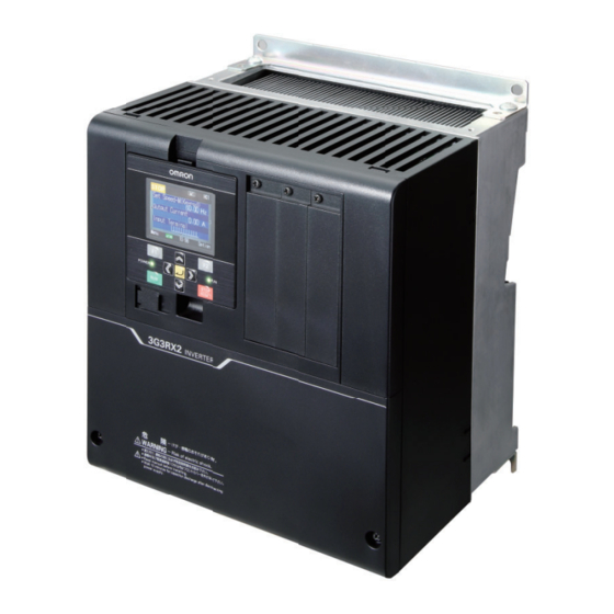
Page 39: Appearance And Part Names
Use this to connect the inverter main power supply, motor, braking resistor, and other devices. Backing plate Cut off the cutout portions of this plate to connect power sup- ply lines, signal lines, etc. 1 - 7 High-function General-purpose Inverter RX2 Series User’s Manual... -
Page 40: Specifications
External start/end (volume/ratio), Frequency input selection, Trip retry, Restart after instantaneous stop, Output of signals, Initialization settings, PID control, Automatic deceleration at power shut-off, Brake control function, and Auto-tuning for commercial switching function (online/offline). 1 - 8 High-function General-purpose Inverter RX2 Series User’s Manual... - Page 41 Braking resistor, AC reactor, DC reactor, noise filter *1. The output frequency range depend on the control and motor used. When running the inverter exceeding 60Hz, check the maximum allowable frequency with the manufacturer of the motor. 1 - 9 High-function General-purpose Inverter RX2 Series User’s Manual...
- Page 42 *14. For insulation distance, comply with UL and CE standards *15. When a clock function is used, the optional battery (CR2032, 3V) is required. When you purchase, this LCD operator does not come with the battery. 1 - 10 High-function General-purpose Inverter RX2 Series User’s Manual...
-
Page 43: Class Specifications
*4. The value of the sensor-less vector control applied to the ND rating in the Standard motor. Torque characteristics may vary depending on the control method and the motor used. *5. Based on self declaration. 1 - 11 High-function General-purpose Inverter RX2 Series User’s Manual... -
Page 44: V Class Specifications
*4. The value of the sensor-less vector control applied to the ND rating in the Standard motor. Torque characteristics may vary depending on the control method and the motor used. *5. Based on self declaration. 1 - 12 High-function General-purpose Inverter RX2 Series User’s Manual... -
Page 45: External Dimensions
1 Overview 1-3-4 External Dimensions 3G3RX2-A2004/A2007/A2015/A2022/A2037/A4007/A4015/A4022/A4037 2-φ6 Installation dimensions 4-M5 1 - 13 High-function General-purpose Inverter RX2 Series User’s Manual... - Page 46 In case you operate 3G3RX2-A2110 at Low Duty (LD) or Very Low Duty (VLD), the inverter is subject to the restriction of installing method. As for the details, refer to 2-1-2 Precaution for Installation on page 2-4. 1 - 14 High-function General-purpose Inverter RX2 Series User’s Manual...
- Page 47 In case you operate 3G3RX2-A2220 at Very Low Duty (VLD), the inverter is subject to the restriction of installing method. As for the details, refer to 2-1-2 Precaution for Installation on page 2-4. 1 - 15 High-function General-purpose Inverter RX2 Series User’s Manual...
- Page 48 1 Overview 3G3RX2-A2300/A4300 2-φ10 Installation dimensions 4-M8 1 - 16 High-function General-purpose Inverter RX2 Series User’s Manual...
- Page 49 1 Overview 3G3RX2-A2370/A2450/A4370/A4450/A4550 2-φ12 Installation dimensions 4-M10 1 - 17 High-function General-purpose Inverter RX2 Series User’s Manual...
- Page 50 1 Overview 3G3RX2-A2550 2-φ12 Installation dimensions 4-M10 1 - 18 High-function General-purpose Inverter RX2 Series User’s Manual...
- Page 51 1 Overview 3G3RX2-B4750/B4900 2-φ12 Installation dimensions 4-M10 1 - 19 High-function General-purpose Inverter RX2 Series User’s Manual...
- Page 52 1 Overview 3G3RX2-B411K/B413K 2-φ12 Installation dimensions 4-M10 1 - 20 High-function General-purpose Inverter RX2 Series User’s Manual...
-
Page 53: Restrictions
When 0-Hz sensorless vector control is used, a large current flows at low frequencies. To protect the inverter against overload, select and use an inverter whose rated capacity is one size larger than the rated capacity of the motor. 1 - 21 High-function General-purpose Inverter RX2 Series User’s Manual... - Page 54 1 Overview 1 - 22 High-function General-purpose Inverter RX2 Series User’s Manual...
- Page 55 Reference Manual for Options ........2-80 2 - 1 High-function General-purpose Inverter RX2 Series User’s Manual...
- Page 56 Setting wrong parameter at startup, adjustment, maintenance and exchange may result in severe damage. Operate the device after sufficient checking. 2 - 2 High-function General-purpose Inverter RX2 Series User’s Manual...
- Page 57 Locations subject to static electricity or other forms of noise Locations subject to strong magnetic fields Locations close to power lines • When using the DriveProgramming, confirm that the program data is downloaded normally before starting operation. 2 - 3 High-function General-purpose Inverter RX2 Series User’s Manual...
-
Page 58: Design
Fix the fittings on the main body by the four screws you removed at step 1. (Torque: 2.2 to 2.5 N·m) Fix the main body on the wall with four other screws you provide. 2 - 4 High-function General-purpose Inverter RX2 Series User’s Manual... - Page 59 Wall Right side view Screws Step 3 Screws you provide Step 4 Mounting method Precautions for Correct Use Set [Ub-03]=00(VLD) or [Ub-03]=01(LD) for Light Duty or Very Light Duty respectively. 2 - 5 High-function General-purpose Inverter RX2 Series User’s Manual...
- Page 60 Step 1 Spacer Wall Screw M3 × 8 Step 2 Screws you provide Mounting method Right side view Precautions for Correct Use Set [Ub-03]=00 for Very Light Duty (VLD) 2 - 6 High-function General-purpose Inverter RX2 Series User’s Manual...
-
Page 61: Installation Environment
• 3G3RX2-A2150 to 3G3RX2-A2220 • 3G3RX2-A4150 to 3G3RX2-A4220 The inverter is needed to be taken off when consumable components are replaced on the following models. • 3G3RX2-A2055 to 3G3RX2-A2110 • 3G3RX2-A4055 to 3G3RX2-A4110 2 - 7 High-function General-purpose Inverter RX2 Series User’s Manual... - Page 62 Be sure to remove the cover after installation is completed. Using the inverter with the cover placed results in poor ventilation, which causes the inverter to overheat. 2 - 8 High-function General-purpose Inverter RX2 Series User’s Manual...
- Page 63 1317 1536 1698 1534 1801 2092 1625 1940 2300 1047 1218 1300 1878 2669 3046 1130 1488 1592 1570 1811 2020 2034 2150 2359 2219 2397 2557 3872 4352 4598 2 - 9 High-function General-purpose Inverter RX2 Series User’s Manual...
- Page 64 17.5A Carrier frequency (kHz) 10 12 14 16 18 Carrier frequency (kHz) • 3G3RX2-A2075 • 3G3RX2-A2110 VLD:60A LD:56A Carrier frequency (kHz) 8 10 12 14 16 18 Carrier frequency (kHz) 2 - 10 High-function General-purpose Inverter RX2 Series User’s Manual...
- Page 65 8 10 12 14 16 18 8 10 12 14 16 18 Carrier frequency (kHz) Carrier frequency (kHz) • 3G3RX2-A2370 • 3G3RX2-A2450 VLD:185A VLD:229A LD:169A LD:210A 146A 182A Carrier frequency (kHz) Carrier frequency (kHz) 2 - 11 High-function General-purpose Inverter RX2 Series User’s Manual...
- Page 66 400 V class • 3G3RX2-A4015 5.4A 4.8A 4.0A 3.2A 1.6A Carrier frequency (kHz) • 3G3RX2-A4022 • 3G3RX2-A4037 VLD:12.6A 8.3A LD:11A 6.7A 5.5A 4.8A 3.7A Carrier frequency (kHz) Carrier frequency (kHz) 2 - 12 High-function General-purpose Inverter RX2 Series User’s Manual...
- Page 67 Carrier frequency (kHz) • 3G3RX2-A4110 • 3G3RX2-A4150 VLD:31A LD:29A 28.3A 11.3A 20.8A Carrier frequency (kHz) Carrier frequency (kHz) • 3G3RX2-A4185 • 3G3RX2-A4220 VLD:62A LD:57A 32.7A Carrier frequency (kHz) Carrier frequency (kHz) 2 - 13 High-function General-purpose Inverter RX2 Series User’s Manual...
- Page 68 Carrier frequency (kHz) Carrier frequency (kHz) • 3G3RX2-A4450 • 3G3RX2-A4550 116A 147A 105A 135A 112A 8 10 12 14 16 18 10 12 14 16 18 Carrier frequency (kHz) Carrier frequency (kHz) 2 - 14 High-function General-purpose Inverter RX2 Series User’s Manual...
- Page 69 180A 150A 73.4A Carrier frequency (kHz) Carrier frequency (kHz) • 3G3RX2-B411K • 3G3RX2-B413K VLD: 252A VLD: 316A LD:230A LD: 290A 217A 260A 135A 135A Carrier frequency (kHz) Carrier frequency (kHz) 2 - 15 High-function General-purpose Inverter RX2 Series User’s Manual...
-
Page 70: Removal Of Each Part
LCD Operator Option Unit Mounting position Control circuit terminal block Wiring separation plate Main circuit terminal block Terminal block cover Backing plate 2 - 16 High-function General-purpose Inverter RX2 Series User’s Manual... -
Page 71: Terminal Blocks
(between the terminal P and N) is approximately 45 V or higher. Make sure the charge indicator is not lit before wiring etc. Slide switch SW1 Enables or disables the emergency shutoff function. USB (micro-B) The USB connector of micro-B for connecting PC 2 - 17 High-function General-purpose Inverter RX2 Series User’s Manual... -
Page 72: Preparing Backing Plate
• Backing plate 1 Wiring of control circuit Wiring of main circuit • Backing plate 2 Connection Wiring of control circuit Wiring of main circuit Unnecessary part 2 - 18 High-function General-purpose Inverter RX2 Series User’s Manual... - Page 73 Do not remove the rubber bushing unless you connect a cable conduit. Doing so may result in damage to the cable sheath by the inner edge of the backing plate, resulting in a short-circuit or ground fault. 2 - 19 High-function General-purpose Inverter RX2 Series User’s Manual...
-
Page 74: Wiring
(± 10V ) input 3 (0V) Thermistor RS485 terminal P24S Modbus communication * The signal ground for RS485 terminal is CM1. STO input EDM output RJ45 Operation section PC(CX-Drive) LCD Operator 2 - 20 High-function General-purpose Inverter RX2 Series User’s Manual... -
Page 75: Arrangement And Function Of Main Circuit Terminal Block
The earth terminal for the Inverter case. Please connect this termi- nal to the ground. Inverter earth terminal Conduct class-D ground work for 200V class, and class-C ground work for 400V class. 2 - 21 High-function General-purpose Inverter RX2 Series User’s Manual... -
Page 76: Arrangement And Function Of Control Circuit Terminal Block
Switches the sink/source logic for input terminals. This switch is enabled when SW5 is IN. Switch of sink/source for SRC/SINK (SW6) the input terminals SINK: Enables sink logic. SRC: Enables source logic. 2 - 22 High-function General-purpose Inverter RX2 Series User’s Manual... - Page 77 • When connecting a relay with output terminals, connect a diode for absorbing surge in paral- lel with the coil. Otherwise, internal elements may burn. 2 - 23 High-function General-purpose Inverter RX2 Series User’s Manual...
- Page 78 • Maximum 32kpps pulse input input. The maximum input pulse is 32kpps. Common Common terminals for digital input for input terminals (1,2,3,4,5,6,7,8,9,A,B). terminal There are three COM terminals. 2 - 24 High-function General-purpose Inverter RX2 Series User’s Manual...
- Page 79 AC250V, 0.2A (induction) 1c relay AL2/AL0: A relay for contact C output. terminal • AC250V, 1A (resistance)/ • AC250V, 0.2A (induction) Minimum capacity of contact (common) • AC100V, 10mA/DC5V, 100mA 2 - 25 High-function General-purpose Inverter RX2 Series User’s Manual...
- Page 80 • Do not short between the analog power supply H and L terminals, power supply P+ and P- terminals, P24 and P- terminals, P+ and CM1 terminals, and P24 and CM1 terminals. Other- wise, the inverter may fail. 2 - 26 High-function General-purpose Inverter RX2 Series User’s Manual...
- Page 81 2 • Allowable load impedance 250Ω monitor data of the inverter. (voltage/current or below switching SW4) • Output current accuracy: ±20% (Ambient temperature: 25±10°C) 2 - 27 High-function General-purpose Inverter RX2 Series User’s Manual...
- Page 82 (power line). • The length of wiring to the thermistor shall be within 20m. FM Output Terminal (Wiring example) Control circuit terminal area Digital output Frequency meter (PWM) 2 - 28 High-function General-purpose Inverter RX2 Series User’s Manual...
- Page 83 (also communication (CM1) used by FM terminal) Disable: Open RP-SN There are are two SP terminals and SN termi- nals each, which are connected internally. Maximum baud rate is 115.2kbps. 2 - 29 High-function General-purpose Inverter RX2 Series User’s Manual...
- Page 84 With input of 24 V power, you (24V) can change parameter settings or oper- 24 VDC±10% ate optional communication without using Terminal Maximum power consumption 1A a control power supply for P24/P+ (0 (zero) V) 2 - 30 High-function General-purpose Inverter RX2 Series User’s Manual...
- Page 85 Control circuit terminal area STO input EDM output ED + ED - P24S STC CMS As for the terminal function, see section 2-3-9 Wiring for STO Function on page 2-73. 2 - 31 High-function General-purpose Inverter RX2 Series User’s Manual...
-
Page 86: Wiring For Main Circuit Terminals
Therefore, use an item with 8 times sensitive current that is shown on the table below. In case the total length of wire exceeds 100 meters, use a CV wire. Total wiring length Sensitive current (mA) 100 m or shorter 300 m or shorter 2 - 32 High-function General-purpose Inverter RX2 Series User’s Manual... - Page 87 It improves output current and volt- age waveform to reduce motor vibration, noise, and radiation noise emitted from the wire to convert output-side waveform to sine wave. It is also effective in suppressing surge voltage. 2 - 33 High-function General-purpose Inverter RX2 Series User’s Manual...
- Page 88 EMC filter PD-P short bar disabled 3G3RX2-A2110 * The EMC filter is enabled/disabled by switching the short bar connector. 3G3RX2-A4110 R0, T0: M4 Earth Terminal: M6 Others: M6 2 - 34 High-function General-purpose Inverter RX2 Series User’s Manual...
- Page 89 Earth terminal: M6 (+1) (RB) Others: M6 OFF G EMC filter PD-P short bar enabled EMC filter disabled * The EMC filter is enabled/disabled by switching the short bar connector. 2 - 35 High-function General-purpose Inverter RX2 Series User’s Manual...
- Page 90 Power supply input wire Motor output wire (L1) (L2) (L3) (+1) (RB) (T1) (T2) (T3) PD-P short bar * The EMC filter is enabled/disabled by switching the short circuit connector. 2 - 36 High-function General-purpose Inverter RX2 Series User’s Manual...
- Page 91 Power supply input wire Motor output wire (L1) (L2) (L3) (T1) (T2) (T3) (+1) (RB) PD-P short bar * The EMC filter is enabled/disabled by switching the short circuit bar. 2 - 37 High-function General-purpose Inverter RX2 Series User’s Manual...
- Page 92 Motor output wire (L1) (L2) (L3) (T1) (T2) (T3) (+1) PD-P short bar * For the switching method of EMC filter, refer to the description on the bottom of the table. 2 - 38 High-function General-purpose Inverter RX2 Series User’s Manual...
- Page 93 (L1) (L2) (L3) (+1) (- ) (T1) (T2) (T3) PD-P short bar * For the switching method of EMC filter, refer to the description on the bottom of the table. 2 - 39 High-function General-purpose Inverter RX2 Series User’s Manual...
- Page 94 Motor output wire (L1) (L2) (L3) (T1) (T2) (T3) (+1) PD-P short bar * For the switching method of EMC filter, refer to the description on the bottom of the table. 2 - 40 High-function General-purpose Inverter RX2 Series User’s Manual...
- Page 95 Power supply input wire (L1) (L2) (L3) (T1) (T2) (T3) (+1) PD-P short bar * For the switching method of EMC filter, refer to the description on the bottom of the table. 2 - 41 High-function General-purpose Inverter RX2 Series User’s Manual...
- Page 96 2 Design Switching method of EMC filters The EMC filter is enabled/disabled by following the description below. Disabled Switching Enable (screw switching) 2 - 42 High-function General-purpose Inverter RX2 Series User’s Manual...
- Page 97 1/0×2 60-8/22-6 (53.5×2) 4/0(107.2) 100-8/22-8 A2370 4(21.2) 15.0 1/0×2 60-8/22-8 (53.5×2) 1/0×2 60-8/22-8 (53.5×2) A2450 4(21.2) 6.0 to 10.0 2/0×2 70-8/22-8 (67.4×2) 350kc(177) 180-10/38-8 A2550 3(26.7) 19.6 3/0×2 80-10/38-8 (85.0×2) 2 - 43 High-function General-purpose Inverter RX2 Series User’s Manual...
- Page 98 60-10/22-8 11.7 (53.5×2) (16.5/12.5) 1/0×2 60-10/38-8 10.0 to 12.0/ (53.5×2) B4900 3(26.7) 11.7 2/0×2 (16.5/12.5) 70-10/38-8 (67.4×2) 2/0×2 70-10/60-8 10.0 to 12.0/ (67.4×2) B411K 1(42.4) 11.7 3/0×2 (16.5/12.5) 80-10/60-8 (85.0×2) 2 - 44 High-function General-purpose Inverter RX2 Series User’s Manual...
- Page 99 When selecting the earth leakage breaker to use between the power supply and the main power supply input terminals (R, S, T), consider the following two points. High-frequency leakage current from inverter The inverter produces a high-frequency leakage current due to its high-speed output switching. 2 - 45 High-function General-purpose Inverter RX2 Series User’s Manual...
- Page 100 AC200 V / 3G3AX-EFI42 AC400 V 3G3AX-EFI43 2.2, 3.7 5.5, 7.5 3G3AX-EFI44 3G3AX-EFI45 3G3AX-EFI46 18.5 3G3AX-EFI47 3G3AX-EFI48 3G3AX-EFI49 18.5 100A 3G3AX-EFI4A 22, 30 45, 55 150A 3G3AX-EFI4B 75, 90 200A 2 - 46 High-function General-purpose Inverter RX2 Series User’s Manual...
- Page 101 Phase R The inverter does not operate. Phase T The inverter operates in a single-phase. Phase S Under voltage or over current could occur, which could lead to the inverter broken. 2 - 47 High-function General-purpose Inverter RX2 Series User’s Manual...
- Page 102 Input noise filter for inverter for general: 3GAX-NFI for EMC: 3GAX-EFI MCCB 3G3RX2 series Power supply Noise filter Inverter 3-phase 200 VAC 3-phase 400 VAC CS/CJ series Other control equipment 2 - 48 High-function General-purpose Inverter RX2 Series User’s Manual...
- Page 103 As the number of harmonics increases, the wave- form of the commercial supply has more distor- Distorted waveform tion. This distortion causes the malfunction of the connected equipment or leads to abnormal heat generation. 2 - 49 High-function General-purpose Inverter RX2 Series User’s Manual...
- Page 104 In case you do not use DC reactor DCL option, do NOT remove the PD-P short bar. If you remove the short-circuit bar with the DC reactor unconnected, the inverter cannot operate because no power is supplied to its main circuit. 2 - 50 High-function General-purpose Inverter RX2 Series User’s Manual...
- Page 105 If you have multiple inverters and use the AC reactor, use one AC reactor for each inverter. Using only one AC reactor for more than one inverter does not provide sufficient reduction. 2 - 51 High-function General-purpose Inverter RX2 Series User’s Manual...
- Page 106 RC value of each thermal relay must be 1.1 times larger than the rated current of the motor. • Set the inverter to detect only overloading that occurred in it by setting the Electronic Thermal Level to the rated output current of the inverter. 2 - 52 High-function General-purpose Inverter RX2 Series User’s Manual...
- Page 107 Keep the cables between the inverter and the motor as short as possible. Iron enclosure Metallic conduit 3G3RX2 series MCCB Power supply Noise filter Inverter Noise filter 3-phase 200 VAC 3-phase 400 VAC 2 - 53 High-function General-purpose Inverter RX2 Series User’s Manual...
- Page 108 Wiring distance between inverter and motor 50 m max. 100 m max. Over 100 m Carrier frequency 10 kHz max. 5 kHz max. 2.5 kHz 2 - 54 High-function General-purpose Inverter RX2 Series User’s Manual...
- Page 109 Using the inverter with only one braking resistor connected may cause damage to the braking resistor. Braking resistor (option) Short bar 2 - 55 High-function General-purpose Inverter RX2 Series User’s Manual...
- Page 110 *1. For RY, select the contact rating according to the ratings of the coils MC1 and MC2. *2. MC1 and MC2 are used not only to provide redundancy, but also to meet safety standards. 2 - 56 High-function General-purpose Inverter RX2 Series User’s Manual...
- Page 111 *2. MC1 and MC2 are used not only to provide redundancy, but also to meet safety standards. *3. You need to set DIP switch to regenerative braking unit as a slave, and wire terminal SL1 and SL2. 2 - 57 High-function General-purpose Inverter RX2 Series User’s Manual...
- Page 112 R0 and T0. (282 to 339 VDC) supply T/L3 400-V class: 380 to 500 VAC (+10%, –15%) (50/60 Hz ±5%) 3A fuses (537 to 707 VDC) Control circuit power supply 2 - 58 High-function General-purpose Inverter RX2 Series User’s Manual...
-
Page 113: Wiring For Control Circuit Terminals
• Do not short-circuit the analog power supply terminals FS and FC and/or the interface power supply terminals P24 and SC. Doing so may result in failure of the inverter. • After wiring, pull the wire slightly to confirm that it is connected properly. 2 - 59 High-function General-purpose Inverter RX2 Series User’s Manual... - Page 114 Precaution for Pulling Out the Wire Pull the wire out of the terminal block, while you keep opening the wire-inserting aperture by pushing the orange part with your screwdriver. 2 - 60 High-function General-purpose Inverter RX2 Series User’s Manual...
- Page 115 • Make sure you must turn on the programmable controller and its external power supply at first before you turn on the inverter’s power supply. Otherwise inverter’s inner data may be altered. 2 - 61 High-function General-purpose Inverter RX2 Series User’s Manual...
- Page 116 2 Design Output Terminals and Programmable Controller Connection Sink Logic DC24V Inverter Input unit Source Logic DC24V Inverter Input unit 2 - 62 High-function General-purpose Inverter RX2 Series User’s Manual...
-
Page 117: Wiring For Pg Option Unit
+5V DC power supply Total supply capacity of EP5 and for encoder EP12 EP12 +12V DC power supply (250 mA max.) Connect to the Functional Grounding connection. Functional Grounding terminal (Screw size: M3) 2 - 63 High-function General-purpose Inverter RX2 Series User’s Manual... - Page 118 The screws which had fixed the cover are needed for fixing the PG Option Unit. Cassette Option Connection RJ45 SLOT1 SLOT2 SLOT3 LCD Operator Unscrew to remove the cover. Those screws are needed later. USB(micro-B) 2 - 64 High-function General-purpose Inverter RX2 Series User’s Manual...
- Page 119 Otherwise, the inverter cannot operate properly. • When removing the PG Option Unit from the inverter, be sure to back the cover of the inverter to the original position. 2 - 65 High-function General-purpose Inverter RX2 Series User’s Manual...
- Page 120 Main body’s surface line Terminal Arrangement on PG Option Unit The arrangement of the terminals on the PG Option Unit 3G3AX-RX2-PG01 is shown below. EP12 EP12 DIP Switch FG Terminal 2 - 66 High-function General-purpose Inverter RX2 Series User’s Manual...
- Page 121 All the dip switches are turned OFF at the factory default setting. Set the switches before installing the device. The switches are located behind the unit. You must set the terminal before installation. 2 - 67 High-function General-purpose Inverter RX2 Series User’s Manual...
- Page 122 RS422 compliant driver ZP , ZN Max.200kp/s Terminating resistor 150 Ω When short-circuited, terminating resistor enabled Terminating resistor 150 Ω When short-circuited, terminating resistor enabled Wiring length 20 m max. 2 - 68 High-function General-purpose Inverter RX2 Series User’s Manual...
- Page 123 Insert the pin-terminal to the terminal block of PG Option Unit. A proper pin-terminal can be inserted without tools. Insert the wire here. In case you use improper pin-terminals, insert the cable by the order of steps of pull-out method with a flathead screwdriver shown below. 2 - 69 High-function General-purpose Inverter RX2 Series User’s Manual...
- Page 124 (EAP/EAN/EBP/EBN/EZP/EZN not connected), turn the DIP switch 1 and 2 to OFF in order to disable the disconnection function. As for the encoder without Z-phase, turn the DIP switch 2 to OFF to disable the detection of Z-phase disconnection. 2 - 70 High-function General-purpose Inverter RX2 Series User’s Manual...
-
Page 125: Wiring For Rs485-Communication Terminals
0.14 to 0.5) 0.14 to 1.0 0.22 to 0.25 Stranded wire (If two equal-sized wires are connected to one pole: 0.14 to 0.2) Stranded wire with 0.25 to 0.5 pin terminal 2 - 71 High-function General-purpose Inverter RX2 Series User’s Manual... - Page 126 For this inverter, the built-in terminating resistor (100Ω) can be connected by shorting the terminals PR and SN. External control equipment Shield Termination resistor Termination resistor enabled Inverter Inverter Inverter 2 - 72 High-function General-purpose Inverter RX2 Series User’s Manual...
-
Page 127: Wiring For Digital Operator
Wiring for STO Function The following describes STO input used at STO function and EDM output. STO input Control circuit terminals ST2 STC P24S STC CMS Wiring at factory default 2 - 73 High-function General-purpose Inverter RX2 Series User’s Manual... - Page 128 • Voltage depression 4 V or below at ON • Maximum allowable voltage EDM signal output - side terminal of EDM signal (STO status 27 V terminal (-) monitor) • Maximum allowable current 50 mA 2 - 74 High-function General-purpose Inverter RX2 Series User’s Manual...
-
Page 129: Conditions Of Conformity Of Eu Directives
Manufacturer and EU Representative Manufacturer: OMRON Corporation Shiokoji Horikawa, Shimogyo-ku, Kyoto, 600-8530 Japan Representative and Importer in EU: OMRON EUROPE B.V. Wegalaan 67-69,2132 JD Hoofddorp, The Netherlands GENERAL: 3G3RX2 series Type inverter is open type AC Inverter with three phase input and three phase output. It is intended to be used in an enclosure. - Page 130 • For the control panel door, use a conductive gasket to improve the shielding effect. • In the same control panel, do not install equipment that generates by design electromagnetic waves, especially radio waves. 2 - 76 High-function General-purpose Inverter RX2 Series User’s Manual...
-
Page 131: Compatibility Conditions Of Ul/Csa Standards
A2004 to A2220 5,000A rms 240V A2300 to A2550 10,000A rms 240V 400V A4007 to A4220 5,000A rms 500V A4300 to A4550,B4750, B4900 10,000A rms 500V B411K, B413K 18,000A rms 500V 2 - 77 High-function General-purpose Inverter RX2 Series User’s Manual... - Page 132 2.5 to 3.0 A4150 A2185 2.5 to 3.0 A4185 A2220 5.5 to 6.6 A4220 Parallel of 1/0 A2300 A4300 Parallel of 1/0 6 to 10 A2370 Parallel of 1/0 A4370 2 - 78 High-function General-purpose Inverter RX2 Series User’s Manual...
- Page 133 A2185 Class J or T A2220 Class J or T A2300 Class J or T A2370 Class J or T A2450 Class J or T A2550 Class J or T 2 - 79 High-function General-purpose Inverter RX2 Series User’s Manual...
-
Page 134: Korean Radio Regulation (Kc)
Regenerating Braking Unit (3G3AX-RBU ) When you desire to reduce the motor’s deceleration time, use this unit in combination with braking resistor Name Instruction Manual number Regenerative Braking Unit 3G3AX-RBU User’s Manual I563-E1 2 - 80 High-function General-purpose Inverter RX2 Series User’s Manual... - Page 135 Name Manual number High-function General-purpose Inverter RX2 Series User’s Manual I620-E1 CX-Drive This is a tool which enables you to edit inverter’s parameter and monitor the inverter status.
- Page 136 2 Design 2 - 82 High-function General-purpose Inverter RX2 Series User’s Manual...
-
Page 137: Operation
Display of Battery Level Warning ....... . . 3-48 3-11 Preventing Read and Write of Unnecessary Data ....3-49 3 - 1 High-function General-purpose Inverter RX2 Series User’s Manual... - Page 138 Outline of CX-Drive ..........3-59 3 - 2 High-function General-purpose Inverter RX2 Series User’s Manual...
-
Page 139: Overview Of Lcd Operator
R0 and T0 in the main circuit and to P+ and P- in the terminal block, it is lit. 5. Operation keys Operating section for indicating and settings. 3 - 3 High-function General-purpose Inverter RX2 Series User’s Manual... -
Page 140: Names Of Operation Keys
Precautions for Safe Use Establish an emergency stop button separately from the stop button at this operator because this button is only available when function is set. 3 - 4 High-function General-purpose Inverter RX2 Series User’s Manual... -
Page 141: Lcd Display
Displays the STO command. <f> Control mode Displays the command control mode. <g> Drive Programming Displays the program operation of DriveProgramming. <h> Special status Displays the operation of special function. 3 - 5 High-function General-purpose Inverter RX2 Series User’s Manual... - Page 142 The operation is suspended due to lack of operation command. If the operation command is issued from the LCD operator, the operation is stopped when STOP the breaking function is enabled. 3 - 6 High-function General-purpose Inverter RX2 Series User’s Manual...
- Page 143 The RUN key is enabled by the [F-OP] terminal or LCD operator. (Normal rotation) >FW The RUN key is enabled by the [F-OP] terminal or LCD operator. (Reverse rotation) >RV (None) The command other than the RUN key is selected 3 - 7 High-function General-purpose Inverter RX2 Series User’s Manual...
- Page 144 Screen for selecting saving location for data uploaded using the R/W function Screen for displaying progress status of uploading using the R/W function Screen for selecting data downloaded using the R/W function 3 - 8 High-function General-purpose Inverter RX2 Series User’s Manual...
- Page 145 From the status that the operation of ST1 and ST2 are both STO (contact point OFF), ST2 transitions to be operation-allowed (contact point ON), and later ST1 is kept STO (contact point OFF) for the STO switching allowable time [bd-02]. 3 - 9 High-function General-purpose Inverter RX2 Series User’s Manual...
- Page 146 Colors varying depending on the inverter’s status are shown in the table below: Backlight color Status White Normal (not related to inverter’s operation and stop) Orange Warning (parameter discrepancy) White and orange Trip (equivalent to alarm LED) (blinking alternatively at one-second interval) 3 - 10 High-function General-purpose Inverter RX2 Series User’s Manual...
-
Page 147: Transition Of Screen Display
Home screen option (o01) Menu Home screen option 01 Scroll mode 01 Controller name 02 R/W function 02 Data displayed at the bottom center 03 System settings Home ---- ---- 46.49Hz Home 46.49Hz 3 - 11 High-function General-purpose Inverter RX2 Series User’s Manual... -
Page 148: How To Set Battery And The Time Setting
Make sure that the following screen comes up. Set the date and time. CTRL - 60.00] STOP NRDY Ez_S Battery of keypad run - down. Set the time again. 2000/01/01 00:00 Optional Menu 0.00Hz device 3 - 12 High-function General-purpose Inverter RX2 Series User’s Manual... - Page 149 • Even without battery, parameters saved in LCD operator and programs for DriveProgram- ming are retained • If you cannot see what is displayed on the LCD operator because the service life is near its end, replace the LCD operator. 3 - 13 High-function General-purpose Inverter RX2 Series User’s Manual...
-
Page 150: Parameter Settings
Output Frequency Menu 29.51 Hz 01 Scroll mode Output current 02 R/W function 11.9 A 03 System settings Input terminal monitor LLLLLLLLLLL Optional Optional Menu 46.49Hz Menu 0.00Hz device device 3 - 14 High-function General-purpose Inverter RX2 Series User’s Manual... - Page 151 Example1) [Hb103] The parameter to change the first IM 5.50kW motor pole number. Example2) [Hb104] The parameter to change the first IM 1:4P motor base frequency. 60.00Hz S-Menu 0.00Hz Next group 3 - 15 High-function General-purpose Inverter RX2 Series User’s Manual...
- Page 152 (1) You can jump to the top parameter of each group by using the right and left ( ) keys. (...<->All parameters<->d: monitor<->F: Command monitor/setting<->...<->U: Initial setting, PDN <->All parameters<->...) 3 - 16 High-function General-purpose Inverter RX2 Series User’s Manual...
- Page 153 (2) Jump function using the F2(Next group) key STOP A: Operation function 00: Parameter setting 00: Common AC -03 Acceleration pattern selection 00: Linear acceleration S-Menu 0.00Hz Next group F2 key 3 - 17 High-function General-purpose Inverter RX2 Series User’s Manual...
-
Page 154: Concurrent Monitor Mode
First main speed command selection changed. 07: Parameter set-up Example2) When the frequency command value is con- trolled in [FA-01] while the frequency command destination is set to 07: Parameter setting. 3 - 18 High-function General-purpose Inverter RX2 Series User’s Manual... - Page 155 Press the F1(1) key to return to the monitor. 0.00 Hz (Tips) AA101 The information currently selected is shown in the lower sec- First main speed command selection tion. 01: [Ai1] terminal “01 [Ai1] terminal” is currently selected. 3 - 19 High-function General-purpose Inverter RX2 Series User’s Manual...
- Page 156 Press the F1(1) key to return to the monitor. 0.00 Hz (Tips) FA-01 The current frequency command is shown in the lower sec- tion. 60.00 Hz Currently, 60.00Hz is input as the command. [0.00-60.00] 3 - 20 High-function General-purpose Inverter RX2 Series User’s Manual...
-
Page 157: Monitor Function
Press the Enter key to confirm the monitoring target. Press Output Frequency the F1(1) key to return to the monitor. 29.51 Hz Input Power 2.14 kW Input terminal monitor LLLLLLLLLLL 3 - 21 High-function General-purpose Inverter RX2 Series User’s Manual... -
Page 158: Setting Screen "Concurrent Monitor
When the Enter key is pressed, the left-most letter of the parameter can be changed. dA-01 Output frequency monitor 0.00 Hz Using the arrow ( ) keys, change [dA-01] to [db-50]. db-50 PID1 output monitor 0.00 % 3 - 22 High-function General-purpose Inverter RX2 Series User’s Manual... -
Page 159: Monitor With Large Characters
What is monitored on the screen with large characters (H04) is the same as the upper monitor of the setting screen (H03) and the first line of three-line monitor screen (H01). 3 - 23 High-function General-purpose Inverter RX2 Series User’s Manual... -
Page 160: Error History Display
Motor overload error details. Press the F1(1) key to return to the monitor. Status 3: Speed control Status 4: Overload limit Status 5: ---- RUN time: 20256 hr ON time: 27248 hr 3 - 24 High-function General-purpose Inverter RX2 Series User’s Manual... -
Page 161: Retry History
Press the Enter key to show details of the selected history Detailed retry history (No. 10) information. Overvoltage error r007 16/06/12 21:11 Output Frequency: 40.03Hz Output Current 11.22A DC voltage: 411.0Vdc Status 1: 3 - 25 High-function General-purpose Inverter RX2 Series User’s Manual... - Page 162 • When the clock function is not used with being retained, the display of error history is shown below. Retry history 6. E001 --/--/-- --:-- 7. E001 --/--/-- --:-- 8. E007 --/--/-- --:-- 9. E001 --/--/-- --:-- 10 .E005 --/--/-- --:-- 3 - 26 High-function General-purpose Inverter RX2 Series User’s Manual...
-
Page 163: Data Copy Function
Select data to be read by using the up and down ( 01 Parameter Data ) keys. Then, confirm the function by pressing the 02 Parameter Data + EzSQ Enter key. 3 - 27 High-function General-purpose Inverter RX2 Series User’s Manual... -
Page 164: Write Function
Select data to be written by using the up and down ( 01 Parameter Data ) keys. Then, confirm the function by pressing the 02 Parameter Data + EzSQ Enter key. 3 - 28 High-function General-purpose Inverter RX2 Series User’s Manual... - Page 165 * Inverter name: No. is unique to each inverter. * Data type is 1: Only parameters or 2: Parameters+EzSQ. * To display date and time, you need to configure clock settings from System settings. 3 - 29 High-function General-purpose Inverter RX2 Series User’s Manual...
-
Page 166: System Settings
*2. To use the clock function, you need an optional battery that is separately sold. (CR2032, 3V) If no electricity is supplied to the inverter, battery replacement is required every two years. 3 - 30 High-function General-purpose Inverter RX2 Series User’s Manual... - Page 167 LCD operator. In such a case, initialize the LCD operator from the System settings, and confirm the settings. If the error on the LCD operator is not solved, the internal memory may be damaged. You need to replace the LCD operator. 3 - 31 High-function General-purpose Inverter RX2 Series User’s Manual...
-
Page 168: Changing The Data Indicated At The Bottom Center
(o03) 01 Torque command The current torque command is displayed during torque control. 02 Time The current time is displayed. 03 Controller name The specified controller (inverter) name is displayed. 3 - 32 High-function General-purpose Inverter RX2 Series User’s Manual... -
Page 169: Parameter Function
All data other than [UA-16] cannot be changed selection Data other than [UA-16] and set frequency cannot be changed Input terminal [CA-01] to [SFT]: Used when the soft-lock function is used on terminals. selection [CA-11] 3 - 33 High-function General-purpose Inverter RX2 Series User’s Manual... -
Page 170: Limiting Displayed Parameters
[UA-21] to 00, you can reduce a great number of displayed items. I you are not using option unit, by setting [UA-22] to 00, you can reduce indications for option unit. 3 - 34 High-function General-purpose Inverter RX2 Series User’s Manual... - Page 171 * amount of boost at the start (IM-0Hz-SLV) HC*13 * selection of whether a secondary-resistance correction is to be conducted (IM-SLV, IM-0Hz-SLV,IM-CLV) HC*14 * selection of reversal prevention (IM-SLV, IM-0Hz-SLV, IM-CLV) 3 - 35 High-function General-purpose Inverter RX2 Series User’s Manual...
- Page 172 Numerator of electronic gear ratio AE-03 Denominator of electronic gear ratio AE-04 Positioning completion range setting AE-05 Positioning completion delay time setting AE-06 Positioning control feed forward AE-07 Position loop gain 3 - 36 High-function General-purpose Inverter RX2 Series User’s Manual...
- Page 173 Acceleration time for multi-speed 2nd speed AC-36 Deceleration time for multi-speed 2nd speed AC-38 Acceleration time for multi-speed 3rd speed AC-40 Deceleration time for multi-speed 3rd speed AC-42 Acceleration time for multi-speed 4th speed 3 - 37 High-function General-purpose Inverter RX2 Series User’s Manual...
- Page 174 * acceleration waiting time AF*33 * stop waiting time AF*34 * brake check waiting time AF*35 * brake release frequency AF*36 * brake release current AF*37 * brake apply frequency 3 - 38 High-function General-purpose Inverter RX2 Series User’s Manual...
- Page 175 * gain mapping maximum speed HA*31 * gain mapping P gain 3 HA*32 * gain mapping I gain 3 HA*33 * gain mapping P gain 4 HA*34 * gain mapping I gain 4 3 - 39 High-function General-purpose Inverter RX2 Series User’s Manual...
- Page 176 PID1 target value 2 (monitor + setting) FA-34 PID1 target value 3 (monitor + setting) AH-02 PID1 deviation minus AH-03 PID1 unit selection (PID1) AH-04 PID1 scale adjustment (0%) AH-05 PID1 scale adjustment (100%) 3 - 40 High-function General-purpose Inverter RX2 Series User’s Manual...
- Page 177 PID2 deviation monitor FA-36 PID2 target value (monitor + setting) AJ-02 PID2 deviation minus AJ-03 PID2 unit selection (PID2) AJ-04 PID2 scale adjustment (0%) AJ-05 PID2 scale adjustment (100%) 3 - 41 High-function General-purpose Inverter RX2 Series User’s Manual...
- Page 178 PID4 scale adjustment (100%) AJ-46 PID4 scale adjustment (decimal point) AJ-47 PID4 target value Input destination selection AJ-50 PID4 target value setting AJ-52 PID4 feedback data Input destination selection AJ-53 PID4 proportional gain 3 - 42 High-function General-purpose Inverter RX2 Series User’s Manual...
- Page 179 Output voltage monitor optional setting value PA-28 Output torque monitor optional output selection PA-29 Output torque monitor optional setting value PA-30 Frequency adjustment optional output selection PA-31 Frequency matching optional setting value 3 - 43 High-function General-purpose Inverter RX2 Series User’s Manual...
-
Page 180: Saving Automatically Changed Parameters
[UA-31] to [UA-62]. Also, when you desire to retrieve history of parameter changes, set selection of user parameter auto- matic setting [UA-30] to 01. Up to 32 changed parameters can be saved. 3 - 44 High-function General-purpose Inverter RX2 Series User’s Manual... -
Page 181: Protecting Parameters By Password
After the setting is performed, changes of data set to [UA-17] other than [UA-16] are locked. Input terminal [CA-01] to [SFT]: Used when the soft-lock function is used on terminals. selection [CA-11] 3 - 45 High-function General-purpose Inverter RX2 Series User’s Manual... - Page 182 If you forget the set password, there is no way to unlock the password lock. Also, the password cannot be investigated by our plant or service station, therefore, care must be taken when set- ting a password. 3 - 46 High-function General-purpose Inverter RX2 Series User’s Manual...
-
Page 183: Display Fixation Function
[AA111] [FW]/[RV] terminals mand selection 3 wire RUN key on the LCD Operator RS485 setting Option 1 Option 2 Option 3 STOP key [AA-13] Disable selection Enable Enable only reset 3 - 47 High-function General-purpose Inverter RX2 Series User’s Manual... -
Page 184: Error Operation On The Lcd Operator
In this case, the output terminal function 080 [LBK] is • If [UA-19] is set to a value other than 00, insert the battery in the LCD operator, and set [UA-19] after configuring time. 3 - 48 High-function General-purpose Inverter RX2 Series User’s Manual... -
Page 185: Preventing Read And Write Of Unnecessary Data
After the parameter is confirmed, if it is set to 01 after data is read for backup, unnecessary read and write can be prevented. Parameter Item Parameter Data Description Data R/W selection [UA-18] R/W enabled. Read and write are possible. R/W disabled. Read and write are prohibited. 3 - 49 High-function General-purpose Inverter RX2 Series User’s Manual... -
Page 186: Inverter Initialization
Parameters other than those of I/O terminal function and communica- tion function are initialized. Only the program data for DriveProgramming are initialized. Initialize Data [Ub-02] Mode 1 (the factory setting) selection Function disabled Initialize [Ub-05] Enable Initialization start 3 - 50 High-function General-purpose Inverter RX2 Series User’s Manual... - Page 187 Example of initialization of the trip history, all the parameters, and the program data for DriveProgram- ming Press right () key on LCD operator. STOP Output Frequency 0.00 Hz Output current 0.0 A Input terminal monitor LLLLLLLLLLL Optional 0.00 device Menu 3 - 51 High-function General-purpose Inverter RX2 Series User’s Manual...
- Page 188 Use up, down, right, and left keys to choose a parameter and Enter key to set it. STOP Output Frequency 0.00 Hz Ub-01 Selection of initialization 00: Disabled 0.00 ---- Back 3 - 52 High-function General-purpose Inverter RX2 Series User’s Manual...
- Page 189 Check the content on the previous screen. The initialization is not done yet. STOP Output Frequency 0.00 Hz Ub-01 Selection of initialization 04: Trip, setting, and EzSQ rip, setting, Optional 0.00 0.00 Menu device 3 - 53 High-function General-purpose Inverter RX2 Series User’s Manual...
- Page 190 Choose Enabled and press Enter key and initialization begins. STOP Ub-05 Initialization start 00 Disabled 01 Initialization start 0.00 Back Save Ub-05 Initialization start 00 Disabled 01 Initialization start Initialization is on-going. Initialization completed is displayed. 3 - 54 High-function General-purpose Inverter RX2 Series User’s Manual...
-
Page 191: Connection And Functions Of Cx-Drive
The inverter/Servo support tool CX-Drive is support software to edit the inverter parameter settings. Installing the OMRON CX-One software on your PC also installs the CX-Drive simultaneously. The 3G3RX2 Series Inverter is supported in the following or higher versions of the CX-Drive product: •... - Page 192 Select “3G3RX2” on [Drive Type]. After that, click the [Settings] button to the right. Set the Inverter Protective Structure, Voltage Class and Maximum Motor Capacity on the [Drive Type Settings] window. After these settings, click the [OK] button to close the [Drive Type Settings] window. 3 - 56 High-function General-purpose Inverter RX2 Series User’s Manual...
- Page 193 Set the [Autodetect Options] in the CX-Drive and use the Autodetect function to automatically con- nect to the inverter. Follow the steps below. Start the CX-Drive and, from the [Drive] menu, select [Autodetect Options] to open the Options window. 3 - 57 High-function General-purpose Inverter RX2 Series User’s Manual...
- Page 194 In the [Advanced Options [Direct (X-Series)]] window, set communications options. After setting communications options, click the [OK] button and close all windows. Then, click [Autodetect]. The Autodetect function starts to create new drive projects automatically. 3 - 58 High-function General-purpose Inverter RX2 Series User’s Manual...
-
Page 195: Outline Of Cx-Drive
[Drive Type] section. In the Drive Type Settings window, set the Software Number that matches that of the inverter. If you cannot find the applicable software number in the CX-Drive’s Software Number list, please upgrade the CX-Drive version. 3 - 59 High-function General-purpose Inverter RX2 Series User’s Manual... - Page 196 Not default and different from the inverter, or Invalid. You can display only parameters with the same icon. • You can select specific parameters and transfer data for only those selected parameters to the inverter. 3 - 60 High-function General-purpose Inverter RX2 Series User’s Manual...
- Page 197 Displays the internal status values of the inverter. These status values [Monitor Mode] are similar to those displayed in the monitor mode (dxxx) of the inverter. [Alarms] Displays an alarm history of the current and past alarms. 3 - 61 High-function General-purpose Inverter RX2 Series User’s Manual...
- Page 198 The Real Time Trance window opens, in which you can monitor the operation status of the inverter. • Up to 8 signals can be traced. • Triggers can be set to the ON/OFF timing of the inverter’s internal status, or numerically. 3 - 62 High-function General-purpose Inverter RX2 Series User’s Manual...
- Page 199 4-5 Simulation Mode ..........4-10 4 - 1 High-function General-purpose Inverter RX2 Series User’s Manual...
-
Page 200: Test Run Method
Set up the inverter control method. items. tive function accord- The items required for running the inverter ing to a load are provided in the following article. Completed 4 - 2 High-function General-purpose Inverter RX2 Series User’s Manual... -
Page 201: Settings And Commands Required For Running The Inverter
Run-command input source selection, 1st-motor [AA111] Main Speed reference monitor [FA-01] Note For details, see 6-3 Operation Command Settings on page 6-19 and 6-4 Frequency Command Settings on page 6-25. 4 - 3 High-function General-purpose Inverter RX2 Series User’s Manual... - Page 202 • For synchronous motor (permanent magnetic motor) (SM (PMM)) Item Parameter Sync.Motor constant R, 1st-motor [Hd110] Sync.Motor constant Ld, 1st-motor [Hd112] Sync.Motor constant Lq, 1st-motor [Hd114] Sync.Motor constant Ke, 1st-motor [Hd116] Sync.Motor constant J, 1st-motor [Hd118] 4 - 4 High-function General-purpose Inverter RX2 Series User’s Manual...
-
Page 203: Operation Only With Lcd Operator
If a frequency command is set in this state, the value will be shown at the bottom command monitor area. STOP Output Frequency 0.00 Hz FA-01 60.00 Hz Option Menu 60.00Hz 4 - 5 High-function General-purpose Inverter RX2 Series User’s Manual... - Page 204 Note that the motor may be burned if the electronic thermal level is not appropriately set. Note The electronic thermal for protecting the inverter works automatically. STOP Output Frequency 0.00 Hz bC110 First electronic thermal level 25.0 A [0.0-75.0] Option Menu 60.00Hz 4 - 6 High-function General-purpose Inverter RX2 Series User’s Manual...
-
Page 205: Conduct A Test Run With Analog Input
• For procedure of changing parameters, see 3-2-1 Scroll Mode on page 3-14. Frequency command source selection [AA101] Set the frequency command source to “01:Ai1 input”. STOP Output Frequency 0.00 Hz AA101 01 [Ai1] terminal Option 0.00Hz Menu 4 - 7 High-function General-purpose Inverter RX2 Series User’s Manual... - Page 206 RUN key on LCD operator at the bottom. Note Normal/reverse rotation can be set at [FW]/[RV] terminal. STOP Output Frequency 0.00 Hz AA111 First operation command selection 00:[FW]/[RV] terminal Option Menu 60.00Hz 4 - 8 High-function General-purpose Inverter RX2 Series User’s Manual...
- Page 207 • In the initial state, the motor is in the V/f control mode, in which voltage is output proportional to the frequency for induction motor control. For control modes, see 7-1 Overview of Motor Control Methods on page 7-3. 4 - 9 High-function General-purpose Inverter RX2 Series User’s Manual...
-
Page 208: Simulation Mode
The simulation mode becomes active. [Procedure] Canceling the simulation mode Set the simulation mode [PA-20] to 00. Turn off the power, and then turn it on again. The simulation mode is canceled. 4 - 10 High-function General-purpose Inverter RX2 Series User’s Manual... - Page 209 Overload prewarning level [CE106] Output Current [Ai1] was input. Output frequency [OL] output • [OL] was turned ON because the output current exceeded the over current detection level 1, 1st motor [CE106]. 4 - 11 High-function General-purpose Inverter RX2 Series User’s Manual...
- Page 210 When [CF-11] Resister data selection is set to 00 (A,V), 0.1 A, 0.1 V When [CF-11] Resister data selection is set to 01 (%), 0.01% (Rated ratio) 3) Drive programming: 0.01% (Rated ratio) 4 - 12 High-function General-purpose Inverter RX2 Series User’s Manual...
-
Page 211: Monitor
Rated Current Monitor ......... 5-20 5 - 1 High-function General-purpose Inverter RX2 Series User’s Manual... - Page 212 5-18 Options Monitor ..........5-28 5 - 2 High-function General-purpose Inverter RX2 Series User’s Manual...
-
Page 213: Frequency Monitor
Displays output frequency with sign. Output frequency [dA-12] -590.00 to 590.00 (Hz) A forward revolution is indicated with + monitor (with sign) sign, and a reverse revolution with -. 5 - 3 High-function General-purpose Inverter RX2 Series User’s Manual... -
Page 214: Frequency Command Monitor
Displays the command frequency Sub Speed refer- Monitor: 0.00 to 590.00 (Hz) [FA-02] selected for the Sub frequency input ence monitor Setting: -590.00 to 590.00 (Hz) source selection, 1st-motor [AA102]. 5 - 4 High-function General-purpose Inverter RX2 Series User’s Manual... -
Page 215: Frequency Conversion Monitor
Output frequency [dA-06] 0.00 to 59000.00 (Hz) Converted output frequency is displayed. conversion monitor Set the gain of frequency conversion mon- Frequency conver- [Ab-01] 0.01 to 100.00 sion gain itor. 5 - 5 High-function General-purpose Inverter RX2 Series User’s Manual... -
Page 216: Speed Detection Value Monitor
32 to 65535 (pls) ting enabled when [CA-90] is set to except for 02. Async.Motor poles set- [Hb103] 2 to 48 (poles) Set the number of motor poles. ting, 1st-motor 5 - 6 High-function General-purpose Inverter RX2 Series User’s Manual... -
Page 217: Acceleration/Deceleration Time Monitor
Item Parameter Data Description Acceleration time [FA-10] 0.00 to 3600.00 (s) Displays the enabled acceleration time. monitor Deceleration time [FA-12] 0.00 to 3600.00 (s) Displays the enabled deceleration time. monitor 5 - 7 High-function General-purpose Inverter RX2 Series User’s Manual... -
Page 218: Operation Direction Monitor
02: F (Normal rotation in Inverter is running under forward rotation Operation direc- [dA-03] tion monitor process) command. 03: r (Reverse rotation in Inverter is running under reverse rotation process) command. 5 - 8 High-function General-purpose Inverter RX2 Series User’s Manual... -
Page 219: I/O Terminal Monitor
• The output terminal monitor is not affected by setting of a/b contact. Parameter Item Parameter Data Description Displays the ON/OFF status of output Output terminal [dA-54] LLLLLLL to HHHHHHH monitor terminals (H: ON; L: OFF). 5 - 9 High-function General-purpose Inverter RX2 Series User’s Manual... -
Page 220: Output Current Monitor
A correct value may not be displayed when the input voltage is low. Parameter Item Parameter Data Description Displays the voltage which is output to the Output voltage [dA-18] 0.0 to 800.0 (V) monitor motor. 5 - 10 High-function General-purpose Inverter RX2 Series User’s Manual... -
Page 221: P-N Voltage Monitor
• When P-N voltage is over around 810 VDC in the class of 400 V inverter. Parameter Item Parameter Data Description DC voltage monitor [dA-40] 0.0 to 1000.0 (V) Displays the P-N voltage of inverter. 5 - 11 High-function General-purpose Inverter RX2 Series User’s Manual... -
Page 222: Operation Time And Count Monitor
Parameter Item Parameter Data Description Checks the number of times the inverter Total start-up count [dC-20] 0 to 65535 (Counts) entered an operation condition from an monitor power-off condition. 5 - 12 High-function General-purpose Inverter RX2 Series User’s Manual... -
Page 223: Cumulative Power-On Count Monitor
• Retry restarts due to instantaneous power failures are not counted. Parameter Item Parameter Data Description Displays numbers of the times when the Power-on count [dC-21] 0 to 65535 (Counts) power supply for control circuit was turned 5 - 13 High-function General-purpose Inverter RX2 Series User’s Manual... -
Page 224: Cooling Fin Temperature Monitor
The temperature error [E021] is generated when the cooling fin temperature exceeds 120°C. Parameter Item Parameter Data Description Cooling fin tempera- [dC-15] -20.0 to 200.0 (°C) Displays the cooling fin temperature ture monitor 5 - 14 High-function General-purpose Inverter RX2 Series User’s Manual... -
Page 225: Power Monitor
Displays a value obtained by multiply- Accumulation input [UA-13] 1 to 1000 ing by gain. power monitor [KHC] Clearing of integrated input [CA-01] to Input terminal function [CA-11] power terminal 5 - 15 High-function General-purpose Inverter RX2 Series User’s Manual... -
Page 226: Output Power Monitor
Displays a value obtained by multiply- Accumulation output [UA-15] 1 to 1000 ing by gain. power monitor [OKHC] Clearing of integrated output [CA-01] to Input terminal function [CA-11] power terminal 5 - 16 High-function General-purpose Inverter RX2 Series User’s Manual... -
Page 227: Life Monitor
[bA-70] method selection stopped. Running depending on the temperature. The fan runs as the fin temperature rises. For operation of cooling fan, see 8-5 Cooling Fan Control on page 8-122. 5 - 17 High-function General-purpose Inverter RX2 Series User’s Manual... -
Page 228: Monitor Of Cumulative Operating Time Of Cooling Fan
Cooling FAN Not carries out. accumulation running [bA-71] Carries out clearance at the set time. time clear selection 5 - 18 High-function General-purpose Inverter RX2 Series User’s Manual... -
Page 229: Electronic Thermal Load Ratio Monitor
The heat characteristics of the inverter has been predetermined. Parameter Item Parameter Data Description Displays the thermal load ratio of the Electronic thermal duty [dA-43] 0.00 to 100.00 (%) ratio monitor CTL inverter. 5 - 19 High-function General-purpose Inverter RX2 Series User’s Manual... -
Page 230: Inverter Rated Monitor
You should also check the rated current and current derating characteristics because they vary depending on load type selections. Parameter Item Parameter Data Description Displays the rated current adopted to the Rated current monitor [dC-02] 0.0 to 6553.5 [A] inverter. 5 - 20 High-function General-purpose Inverter RX2 Series User’s Manual... -
Page 231: Braking Resistor Load Ratio Monitor
Displays the load ratio of braking resis- BRD load factor monitor [dA-41] 0.00 to 100.00 (%) tor. Sets the maximum use rate of braking Dynamic brake usage rate [bA-60] 0.0 to 100.0 (%) resistor. 5 - 21 High-function General-purpose Inverter RX2 Series User’s Manual... -
Page 232: Inverter Status Monitor
The inverter thermal load is increased. in effect. Motor heating advance notice in Motor temperature is rising. effect. A state other than those above. A state other than those above. 5 - 22 High-function General-purpose Inverter RX2 Series User’s Manual... - Page 233 Free-run is enabled (free-run operation). Operation command isn’t permitted. Or forced stop is being Forced stop state. issued. (Deceleration stop behavior) A state other than those above. A state other than those above. 5 - 23 High-function General-purpose Inverter RX2 Series User’s Manual...
-
Page 234: Analog Input Value Monitor
Analog input [Ai2] monitor [dA-62] 0.00 to 100.00 (%) [Ai1][Ai2]: 0 to 10V/0 to 20mA Analog input [Ai3] monitor [dA-63] -100.00 to 100.00 (%) [Ai3]: Equivalent to -10 to 10V 5 - 24 High-function General-purpose Inverter RX2 Series User’s Manual... -
Page 235: Analog Terminal Setting Monitor
Analog I/O selection VVVVVVVV to [dA-60] [Left side] (Reserved) (Reserved) (Reserved) (terminal monitor AAAAAAAA Ai3 (Ii3/Vi3)) (terminal Ao2) (terminal Ao1) (terminal Ai2) (terminal Ai1) [Right side] V: voltage/A: current 5 - 25 High-function General-purpose Inverter RX2 Series User’s Manual... -
Page 236: Terminal Block Type Monitor
Displays options for a terminal block that is equipped with inverter. Parameter Item Parameter Data Description Terminal block option mounted [dA-50] 00 (standard) Displays terminal block option types. status 5 - 26 High-function General-purpose Inverter RX2 Series User’s Manual... -
Page 237: Operation Command/Frequency Command Sources Monitor
34 (AHD retention speed) 00 ([FW]/[RV] terminal)/01 (3 wire)/ 02 (RUN key on LCD operator)/ Operation command [dC-10] 00 to 06 destination monitor 03 (RS485 setting)/04 (Option 1)/ 05 (Option 2)/06 (Option 3) 5 - 27 High-function General-purpose Inverter RX2 Series User’s Manual... -
Page 238: Options Monitor
Displays the ID of optional Unit mounted in Option slot 3 mounted [dA-83] Option ID state the option slot 3. Option ID Optional Unit type Description RX2-PG PG Option Unit 5 - 28 High-function General-purpose Inverter RX2 Series User’s Manual... - Page 239 Frequency Command Selection ........6-25 6 - 1 High-function General-purpose Inverter RX2 Series User’s Manual...
- Page 240 Following Frequency Command ........6-70 6 - 2 High-function General-purpose Inverter RX2 Series User’s Manual...
-
Page 241: Inverter Load Rating Settings
Parameters Default Item Parameters Data Description data VLD (Very Low Duty) Load type selection [Ub-03] LD (Low Duty) ND (Normal Duty) 6 - 3 High-function General-purpose Inverter RX2 Series User’s Manual... - Page 242 (SM/PMM) Major Lifts, cranes, etc. applica- tions Conveyors, transportation machines, etc. Fans, pumps *1. PG option unit of the optional unit is necessary for the vector control with sensor. 6 - 4 High-function General-purpose Inverter RX2 Series User’s Manual...
-
Page 243: Inverter Initialization
• During soft lock • Even when the operation command is input during initialization, the inverter ignores the com- mand. Input the operation command again after the initialization is finished. 6 - 5 High-function General-purpose Inverter RX2 Series User’s Manual... - Page 244 [CC-20] to [CC-33] Output delay [CC-40] to [CC-60] Logical operation function [CF-01] to [CF-10] Setting of RS485 communication Classification of communication functions [CF-20] to [CF-38] Setting of EzCOM communication 6 - 6 High-function General-purpose Inverter RX2 Series User’s Manual...
- Page 245 200 V class: 200 200 V class: 230 200 V class: 230 200 V class: 230 2nd-motor 400 V class: 400 400 V class: 400 400 V class: 460 400 V class: 400 6 - 7 High-function General-purpose Inverter RX2 Series User’s Manual...
-
Page 246: Parameter Setting For Motor Related
Sets the rated current of on inverter Current [Hb108] current, 1st-motor motor. models and settings of duty rating. *1. Default data when default data selection (UB-02) is set to 01. 6 - 8 High-function General-purpose Inverter RX2 Series User’s Manual... - Page 247 • The motor could burn if the maximum frequency and rated voltage are set to exceed the specified range of rated voltage. • After initialization, the motor protection function needs to be configured again. Otherwise, the motor could burn. 6 - 9 High-function General-purpose Inverter RX2 Series User’s Manual...
- Page 248 Precautions for Correct Use Expected characteristics may not be obtained if the motor rated current is set higher than the inverter rated current. In some cases, the inverter protection works first. 6 - 10 High-function General-purpose Inverter RX2 Series User’s Manual...
- Page 249 Basically the synchronous motor needs current calculation control and the motor parameters need to be set. The parameters in this item and motor constants in the next item need to be set. 6 - 11 High-function General-purpose Inverter RX2 Series User’s Manual...
-
Page 250: Motor Constant Setting
• Please be advised to save the constants using the R/W function on the LCD operator. • For details of adjustment, see 7-1 Overview of Motor Control Methods on page 7-3. 6 - 12 High-function General-purpose Inverter RX2 Series User’s Manual... - Page 251 Base (maximum) frequency (Hz) = rated number of revolutions (min ) × number of poles (pole)/120 • The motor constant Ke is the peak value of the phase inducted voltage (mV) per electrical angular speed (rad/s). 6 - 13 High-function General-purpose Inverter RX2 Series User’s Manual...
-
Page 252: Auto-Tuning Of Motor
• For a machine with limited motor axis rotation (lift, ball screw, etc.), 01 (non-revolving) should be chosen in [HA-01] since rotation higher than the allowed one could occur causing a dam- age to the machine. 6 - 14 High-function General-purpose Inverter RX2 Series User’s Manual... - Page 253 • Even if 01 (non-revolving) is chosen for [HA-01], the motor could make a half-turn at the max- imum. • The offline auto-tuning automatically overwrites the parameters with acquired data. The online auto-tuning does not overwrite the parameters with the data as it corrects internal data. 6 - 15 High-function General-purpose Inverter RX2 Series User’s Manual...
- Page 254 After the above operation finishes, the output with no revolution is checked as final check. The tuning finished. When the tuning End display appears, the tuning finishes. Use STOP key to cancel the End dis- play. 6 - 16 High-function General-purpose Inverter RX2 Series User’s Manual...
- Page 255 Precautions for Correct Use In case of failure of the auto-tuning, the motor constant data are not updated and the motor works in the untuned state. 6 - 17 High-function General-purpose Inverter RX2 Series User’s Manual...
- Page 256 • In case of failure of the auto-tuning with the IVMS control, data necessary for the IVMS con- trol cannot be obtained from the motor and the Control mode selection, 1st-motor [AA121] should be set to 11 (SM/PMM: Synchronous activation) to drive the motor. 6 - 18 High-function General-purpose Inverter RX2 Series User’s Manual...
-
Page 257: Operation Command Settings
• If the forced operation 023 [F-OP] of the terminal function is enabled, the command destina- tion specified in the [F-OP] function becomes effective irrespective of the present setting. 6 - 19 High-function General-purpose Inverter RX2 Series User’s Manual... -
Page 258: Operation With Forward/Reverse Rotation Terminal
• The output of the inverter requires not only an operation command but also a frequency com- mand. • In case the input terminal function 023 [F-OP] is enabled, the command destination specified in the [F-OP] function becomes effective irrespective of the present setting. 6 - 20 High-function General-purpose Inverter RX2 Series User’s Manual... -
Page 259: Operation With 3 Wire Function Of Terminal Block
018 [F/R] terminal function switches forward and reverse rotations by the contact. The terminal action is made in the following way. Forward rotation Output Reverse speed rotation 6 - 21 High-function General-purpose Inverter RX2 Series User’s Manual... -
Page 260: Operation With Rs485 Communication
• The output of the inverter requires not only an operation command but also a frequency com- mand. • The terminal 023 [F-OP] is enabled, the command destination specified in the [F-OP] func- tion becomes effective irrespective of the present setting. 6 - 22 High-function General-purpose Inverter RX2 Series User’s Manual... -
Page 261: Disabling The Keys On Lcd Operator
LCD operator (02). • Unlike 3G3RX-V1 Series, the communication function on 3G3RX2 Series continues commu- nication even during resetting and therefore no idling time is necessary for the resetting. 6 - 23 High-function General-purpose Inverter RX2 Series User’s Manual... -
Page 262: Temporary Change Of Operation Command Destination
RUN command source 02: RUN key on LCD operator, selection at [F-OP] is [CA-71] 00 to 06 03: RS485 communication, 04: option 1, active 05: option 2, 06: option 3 6 - 24 High-function General-purpose Inverter RX2 Series User’s Manual... -
Page 263: Frequency Command Settings
Operation switching 015[SCHG] Operator Auxiliary speed [AA105] A A 105 Auxiliary speed Main speed [AA102] ≠00 ≠00 Operator [AA105] (00to 15) Arithmetic operation +(01), - (02), function x(03) Arithmetic 6 - 25 High-function General-purpose Inverter RX2 Series User’s Manual... -
Page 264: Case Where Command Is Given With Lcd Operator
Given with Main Speed Command and Auxiliary Speed Command on page 6-35. • If not using the LCD operator, you need to make FW/RV direction switching from each com- mand. 6 - 26 High-function General-purpose Inverter RX2 Series User’s Manual... -
Page 265: Case Where Command Is Given From Terminal Block Analog Signals
• Note that the voltage input and the current input are switched from each other by the terminal block switch. • For adjustment of the analog input, see 8-10 Input Terminal Function on page 8-154. 6 - 27 High-function General-purpose Inverter RX2 Series User’s Manual... -
Page 266: Case Where Command Is Given Through Rs485 Communications
Frequency command is given with a pulse string input. Note To give a pulse string input, there are two methods. One is to use the main body’s terminals and the other is to use the PG option unit. 6 - 28 High-function General-purpose Inverter RX2 Series User’s Manual... - Page 267 0.0 to 100.0 [CA-96] pulses with the frequency lower than the limit is detection low level set to 0.0%. *1. Default data when default data selection (UB-02) is set to 01. 6 - 29 High-function General-purpose Inverter RX2 Series User’s Manual...
- Page 268 Time b) Mode 1: [CA-91]=01 forward and reverse rotation commands + pulse string Pulse string Terminal input Forward/Reverse Terminal rotation command Number of detected pulses Positive (+) Negative (-) Time 6 - 30 High-function General-purpose Inverter RX2 Series User’s Manual...
- Page 269 • When the pulse input frequency is below the pulse string frequency lower detection limit [ob-16], it is regarded as 0 Hz in the processing. • Slow start if the pulse string frequency lower detection limit [ob-16] is set to a high value. 6 - 31 High-function General-purpose Inverter RX2 Series User’s Manual...
- Page 270 IM:[Hb105] -100 Pulse string frequency scale Filter time SM:[Hd105] Input G [ob-12] constant T [ob-13] (0.05kHz-32.00kHz) (0.01s-2.00s) Upper limit [ob-15] Lower limit [ob-16] (0.00%-100.00%) (0.01%-100.00%) Pulse string frequency processing block 6 - 32 High-function General-purpose Inverter RX2 Series User’s Manual...
- Page 271 Your setting must be in accordance with the pulse string input to use. Make sure to set the proper pulse string input (option) mode selection: [ob-11]. If your setting is incorrect, the motor could make reverse rotations or other unintended movements. 6 - 33 High-function General-purpose Inverter RX2 Series User’s Manual...
-
Page 272: Case Where Command Is Given Through Driveprogramming
Description data Main speed input source selection, [AA101] An arithmetic result of the PID control is output. 1st-motor *1. Default data when default data selection (UB-02) is set to 01. 6 - 34 High-function General-purpose Inverter RX2 Series User’s Manual... -
Page 273: Case Where Command Is Given With Main Speed Command And Auxiliary Speed Command
(Ex.1) Gain is multiplied. [AA101]=01 ([Ai1] command)/[AA102]=07 (set [Ab110])/[AA105]=03 (multiplication)/[Ab110]=3.00(Hz) Main speed Analog input Ai1 command 20Hz Auxiliary speed [Ab110] command 3.00Hz 60Hz Main speed x Frequency auxiliary speed command 6 - 35 High-function General-purpose Inverter RX2 Series User’s Manual... - Page 274 Main speed or 40Hz Frequency auxiliary speed command 3.00Hz Precautions for Correct Use The output frequency of the inverter accelerates/decelerates toward the frequency command, following the setting of the acceleration/deceleration time. 6 - 36 High-function General-purpose Inverter RX2 Series User’s Manual...
-
Page 275: Case Where Command Is Given With Multi-Step Speed
1st-15th speeds of the multi-step speed 0.00 [Ab-25] ting quency (Hz) Multistage input deter- This is the time to fix the frequency in [CA-55] 0 to 2000(ms) mination time switching the multi-step speed. 6 - 37 High-function General-purpose Inverter RX2 Series User’s Manual... - Page 276 15th speed 4th speed 5th speed 0th speed 3rd speed 6th speed 2nd speed Frequency command from 7th speed the place selected for the 1st speed frequency command 8th speed 6 - 38 High-function General-purpose Inverter RX2 Series User’s Manual...
- Page 277 “-” in the table indicates that a frequency is chosen independently from ON/OFF state of the terminals. • For the command frequency of the 0th speed, the command designated in the main speed selection [AA101] is used. The following table is for [AA101]=07. 6 - 39 High-function General-purpose Inverter RX2 Series User’s Manual...
- Page 278 S S F F 3 S S F F 2 S S F F 1 speed 1st speed 2nd speed 3rd speed If SF1 becomes ON in this state, the 1st speed becomes effective. 6 - 40 High-function General-purpose Inverter RX2 Series User’s Manual...
-
Page 279: Temporal Addition Of Frequency Command
• When 020 [FUP] terminal / 021 [FDN] terminal is made ON/OFF immediately after the power shutdown, data may not be able to be correctly saved. • Cannot be used to set the frequency of the input terminal function 029 [JG] jogging operation. 6 - 41 High-function General-purpose Inverter RX2 Series User’s Manual... -
Page 280: Analog Command Hold Function (Ahd)
[AHD] function. If 019[AHD] function is effective, the held data can be moved up/down by using [FUP]/[FDN] function. Precautions for Correct Use Data changes with the [FUP]/[FDN] function are not saved. 6 - 42 High-function General-purpose Inverter RX2 Series User’s Manual... -
Page 281: Temporal Change Of Frequency Command Destinations
RUN command source 02: RUN key on LCD operator, selection at [F-OP] is [CA-71] 00 to 06 03: RS485 communication, 04: option 1, active 05: option 2, 06: option 3 6 - 43 High-function General-purpose Inverter RX2 Series User’s Manual... -
Page 282: Limit Frequency And Operation Commands
(Hz) Frequency upper limit 0.00 to The employed upper limit of the frequency is [dA-14] monitor 590.00(Hz) shown. *1. Default data when default data selection (UB-02) is set to 01. 6 - 44 High-function General-purpose Inverter RX2 Series User’s Manual... -
Page 283: Limit Operation Command Direction
[HC114] is used. Enable the reverse rotation prevention function selection if the reverse rotation of the motor could give damage to the connected machine. 6 - 45 High-function General-purpose Inverter RX2 Series User’s Manual... -
Page 284: Operation Permission
The operation does not start if [REN] is set to OFF. To make output from the inverter based on an operation command in a trial operation, [REN] needs to be set to 000[no] temporarily. Output Frequency REN input Operation command FW, RV input Output Signal [RUN] 6 - 46 High-function General-purpose Inverter RX2 Series User’s Manual... - Page 285 6 Basic Parameter Settings Parameter Item Parameters Data Description [REN]: Controls Permitted/Not permitted using operation permission signal. [CA-01] to Input terminal function [CA-11] ON: Allowed OFF: Not allowed 6 - 47 High-function General-purpose Inverter RX2 Series User’s Manual...
-
Page 286: Thermal Protection Of Motor (Electronic Thermal)
The magnification ratio and hence the time to a trip could change depending on the choice of the elec- tronic thermal characteristic. A trip occurs in 60 seconds when an electric current of 150% of the electronic thermal level x1 flows continuously. 6 - 48 High-function General-purpose Inverter RX2 Series User’s Manual... - Page 287 [bC111] Pattern for constant output selection, 1st-motor Free setting: Multiple patterns are available according to the motor characteristics. *1. Default data when default data selection (UB-02) is set to 01. 6 - 49 High-function General-purpose Inverter RX2 Series User’s Manual...
- Page 288 150% ×1 of the motor rated current flows continuously. However in Example 2, a trip occurs in 60 seconds when an electric current of 150%×0.8=120% of the motor rated current flows continuously. 6 - 50 High-function General-purpose Inverter RX2 Series User’s Manual...
- Page 289 3 is the same as the one in the example 1. Free Settings [bC111]=02 To protect the motor, the electronic thermal characteristics can be freely set in accordance with the load. 6 - 51 High-function General-purpose Inverter RX2 Series User’s Manual...
- Page 290 • When [bC121][bC123][bC125] are set as default (0.00) and [bC111] electronic thermal is set as 02, E005 is generated. • Set the free electronic thermal frequency in the order of [bC125], [bC123] and [bC121]. At that time, set in the following manner: [bC125]≥[bC123]≥[bC121]. 6 - 52 High-function General-purpose Inverter RX2 Series User’s Manual...
- Page 291 The temperature integration data are cleared every 10 minutes. Electronic thermal Subtraction function [bC112] Valid: Subtraction mode enable, 1st-motor The temperature integration data are subtracted in accordance with the heat emission of the motor. 6 - 53 High-function General-purpose Inverter RX2 Series User’s Manual...
- Page 292 If you want a warning signal when the electronic thermal exceeds a certain level, set the output signal function 027 [THC] and [CE-31] electronic thermal warning level (controller). For details, see 8-6-9 Inverter Thermal Warning Signal (THC) on page 8-134. 6 - 54 High-function General-purpose Inverter RX2 Series User’s Manual...
-
Page 293: Monitoring Of Motor Temperature
Enabled Negative temperature coefficient resis- tor (NTC) Thermistor gain [Cb-41] 0.0 to 1000. Use as gain adjustment. 100.0 adjustment Motor temperature -20.0 to [dA-38] Indicates the detected motor temperature. 200.0(C°) monitor 6 - 55 High-function General-purpose Inverter RX2 Series User’s Manual... -
Page 294: Acceleration/Deceleration Settings
• The acceleration or deceleration time may be changed in response to the command given by the multi-speed function. For details, see 6-4-9 Case where Command Is Given with Multi-Step Speed on page 6-37. 6 - 56 High-function General-purpose Inverter RX2 Series User’s Manual... - Page 295 J of the mechanical system and the motor torque. An act of acceleration or deceleration in a shorter time than the minimum acceleration or deceleration time may cause an over current or over voltage trip to happen. 6 - 57 High-function General-purpose Inverter RX2 Series User’s Manual...
-
Page 296: Switch Acceleration Time And Deceleration Time In Two Stages
[AC115] is 01. point, 1st-motor Decel1 to Decel2 Fre- Enabled when 2-stage acceleration or decelera- 0.00 to quency transition [AC117] 0.00 590.00(Hz) tion selection [AC115] is 01. point, 1st-motor 6 - 58 High-function General-purpose Inverter RX2 Series User’s Manual... - Page 297 2. (Example 1) In the case of setting [AC115] = 00 Output frequency Acceleration Deceleration time 2 time 2 Acceleration Deceleration time 1 time 1 6 - 59 High-function General-purpose Inverter RX2 Series User’s Manual...
- Page 298 1 (Example 3) In the case of setting [AC115] = 02 Deceleration Acceleration time 2 time 1 Forward-revolution output frequency Acceleration Backward-revolution Deceleration time 1 time 2 output frequency 6 - 60 High-function General-purpose Inverter RX2 Series User’s Manual...
-
Page 299: Switching Of Acceleration Or Deceleration Time With Multi-Speed Step
Corresponding to 8-speed bit operation. 007[SF1] to 013[SF7] Implementing the multi-speed command. Input terminal function 003 to 006/ [CA-01] to [CA-11] 003[CF1] to 006[CF4]/007[SF1] to 007 to 013 selection 013[SF7] 6 - 61 High-function General-purpose Inverter RX2 Series User’s Manual... - Page 300 Table for Bit Operation [Ab-03] = 01; Input terminal function 007 [SF1] to 013 [SF7] Multiple speeds 0th speed 1st speed 2nd speed 3rd speed 4th speed 5th speed 6th speed 7th speed 6 - 62 High-function General-purpose Inverter RX2 Series User’s Manual...
- Page 301 Example (2) If the multi-speed 1st speed is engaged and the revolution is decelerating, the enabled deceleration time is the deceleration time setting for Multispeed-3 [AC-40] for the multi-speed 3rd speed that has been engaged until the multi-speed 1st speed is engaged. 6 - 63 High-function General-purpose Inverter RX2 Series User’s Manual...
- Page 302 Multi-speed 15th speed [Ab-25] > Fre- Acceleration time for multi-speed 15th speed ON quency before 15th speed is ON 15th speed [AC-86] No multi-speed Other than those above Acceleration time [AC120] 6 - 64 High-function General-purpose Inverter RX2 Series User’s Manual...
- Page 303 [Ab-12] [Ab-12] [AC-36] [Ab-11] [AC-34] [Ab-11] Output Output frequency frequency Frequency 1st speed 2nd speed Frequency 2nd speed 1st speed command command Deceleration Acceleration time time speed speed 6 - 65 High-function General-purpose Inverter RX2 Series User’s Manual...
-
Page 304: Holding Function Of Acceleration/Deceleration
Case where Setting Time is held with Any Frequency Output frequency [AG11 2] [AG11 3] [AG11 0] [AG111] Time Case where Frequency is held with Input Terminal 100 [HLD] Terminal Function Output frequency Time [HLD] O FF 6 - 66 High-function General-purpose Inverter RX2 Series User’s Manual... -
Page 305: Change The Acceleration Or Deceleration Pattern
An unsteady command value may cause a recal- culation of the acceleration or deceleration pattern, which may prolong the actual accelera- tion or deceleration time. 6 - 67 High-function General-purpose Inverter RX2 Series User’s Manual... - Page 306 Acceleration time until the set Acceleration time until the set value for the frequency is value for the frequency is value for the frequency is reached (100%) reached (100%) reached (100%) 6 - 68 High-function General-purpose Inverter RX2 Series User’s Manual...
- Page 307 EL-S-curve ratio @start of [AC-10] Designate the curvature of the curved deceleration 0 to 100(%) sector when an EL-S-shaped pattern is EL-S-curve ratio @end of used. (For deceleration) [AC-11] deceleration 6 - 69 High-function General-purpose Inverter RX2 Series User’s Manual...
-
Page 308: Following Frequency Command
[CA-11] selection Canceling the acceleration or deceleration and making the output follow the command Analog frequency command Output frequency Follow the acceleration or deceleration time Following the Time command [LAC] 6 - 70 High-function General-purpose Inverter RX2 Series User’s Manual... - Page 309 7-3 Torque Control ..........7-43 7 - 1 High-function General-purpose Inverter RX2 Series User’s Manual...
- Page 310 DC Braking for Stopping (Servo Lock Control) ..... . . 7-90 7 - 2 High-function General-purpose Inverter RX2 Series User’s Manual...
-
Page 311: Overview Of Motor Control Methods
*1. Cannot be selected if [Ub-03] duty spec selection is 01 (LD) or 00 (VLD). *2. Cannot be selected if [Ub-03] duty spec selection is 00 (VLD). Note IM: Induction motor SM (PMM): Synchronous motor (permanent magnet motor) 7 - 3 High-function General-purpose Inverter RX2 Series User’s Manual... - Page 312 Proceed to 7-2-12 V/f Control with Sensor (Constant Torque Characteristics) on page 7-32. Precautions for Correct Use To conduct encoder feedback, see also 7-2-16 Encoder Feedback Control on page 7-37. 7 - 4 High-function General-purpose Inverter RX2 Series User’s Manual...
-
Page 313: Selection Of Motor Control Methods
• When a single inverter runs multiple motors and the motors are vibrating, a downward adjust- ment of the stabilization constant, 1st-motor [HA110] may stabilize the state of the motors. Output voltage (V) Rated voltage Command frequency (Hz) Base frequency Maximum frequency 7 - 5 High-function General-purpose Inverter RX2 Series User’s Manual... -
Page 314: V/F Control (Reducing Torque Characteristics)
Period c: The voltage has constant-output characteristics for a range from the base frequency to the maximum frequency. Precautions for Correct Use When a motor is hunting and vibrating, an adjustment of the stabilization constant, 1st-motor [HA110] may improve the state of the motor. 7 - 6 High-function General-purpose Inverter RX2 Series User’s Manual... -
Page 315: V/F Control (Free V/F)
In such way, a motor can be controlled with the output torque according to loads. Output voltage (V) Rated voltage V2,V3 Output frequency (Hz) Base Maximum frequency frequency 7 - 7 High-function General-purpose Inverter RX2 Series User’s Manual... - Page 316 • Default data of frequency for Free V/f setting is 0Hz. Even when you set Control mode selection, 1st-motor [AA121] to 02 ([V/f] Free V/f (IM)), you can not operate an inverter. Be sure to set the frequency for Free V/f setting. 7 - 8 High-function General-purpose Inverter RX2 Series User’s Manual...
- Page 317 Free-V/f Voltage 3 [Hb155] setting, 1st-motor Free-V/f Voltage 2 [Hb153] setting, 1st-motor Free-V/f Voltage 1 [Hb151] setting, 1st-motor *1. Default data when default data selection (UB-02) is set to 01. 7 - 9 High-function General-purpose Inverter RX2 Series User’s Manual...
-
Page 318: Energy-Saving Mode
Select whether or not to conduct the Eco drive enable, [Hb145] 1st-motor 01: enabled energy-saving operation. Setting Response Accuracy Eco drive response Slow High adjustment, [Hb146] 0 to 100(%) ↨ ↨ ↨ 1st-motor Fast 7 - 10 High-function General-purpose Inverter RX2 Series User’s Manual... -
Page 319: Manual Torque Boost
Boosting increases the flow of the current, which may burn the motor. • The target of the torque boost is the V/f control of induction motors. (except the free V/f) 7 - 11 High-function General-purpose Inverter RX2 Series User’s Manual... -
Page 320: Automatic Torque Boost
1st-motor (bA146) to 00: Enabled. • When the motor performs below its potential characteristics, conduct the auto-tuning and make adjustment by referring to the next section. 7 - 12 High-function General-purpose Inverter RX2 Series User’s Manual... - Page 321 An excessive fre- Make an adjustment by decrementing the automatic torque an over current. quency correction boost slip compensation gain [HC102] by approximately 5% raises the frequency. each time 7 - 13 High-function General-purpose Inverter RX2 Series User’s Manual...
-
Page 322: Stabilization Of Motor Rotation
If no effect can be observed, restore the original values. Precautions for Correct Use Do not conduct a steady operation with a setting for the output voltage gain, 1st-motor [Hb180] that exceeds 100%. The motor may be burned. 7 - 14 High-function General-purpose Inverter RX2 Series User’s Manual... -
Page 323: Sensorless Vector Control
• As the capacity becomes farther away from the maximum applicable motor capacity, suffi- cient operation characteristics becomes more difficult to get. 7 - 15 High-function General-purpose Inverter RX2 Series User’s Manual... - Page 324 • Make an adjustment by incrementing the IM motor constant speeds. frequency becomes I0 [Hb116] by 5% of the current value each time. higher. 7 - 16 High-function General-purpose Inverter RX2 Series User’s Manual...
-
Page 325: Zero-Speed Range (Zero-Hz Range) Sensorless Vector Control
• In the case that a length of a wire is over 20 m, the motor’s characteristic may be below what are expected. • As the capacity becomes farther away from the maximum applicable motor capacity, suffi- cient operation characteristics becomes more difficult to get. 7 - 17 High-function General-purpose Inverter RX2 Series User’s Manual... - Page 326 [dA-01], a function to automatically change the frequencies for the overload limiting function, the momentary-stop non-stop function, the over voltage suppression function may work depending upon the settings of the functions. 7 - 18 High-function General-purpose Inverter RX2 Series User’s Manual...
-
Page 327: Vector Control With Sensor
• Once [HC113] Secondary resistance correction, 1st-motor is enabled, a slip change of motor rotation according to temperature change is corrected. Connect a thermistor, which mea- sures the motor temperature, to TH terminals. 7 - 19 High-function General-purpose Inverter RX2 Series User’s Manual... - Page 328 To adjust the feed forward control of the speed ward compensa- [HC121] 0 to 1000 (%) controller. tion gain, 1st-motor *1. Cannot be selected if [Ub-03] duty spec selection is 01 (LD) or 00 (VLD). 7 - 20 High-function General-purpose Inverter RX2 Series User’s Manual...
- Page 329 [dA-01], a function to automatically change the frequencies for the overload limiting function, the momentary-stop non-stop function, the over voltage suppression function may work depending upon the settings of the functions. 7 - 21 High-function General-purpose Inverter RX2 Series User’s Manual...
-
Page 330: Synchronous Motor (Permanent Magnet Motor) Control
Failure to acquire the correct position may occur, which may result in unintended revolution, over current, or loss of syn- chronization. 7 - 22 High-function General-purpose Inverter RX2 Series User’s Manual... - Page 331 Acceleration or decelera- Acceleration or deceleration can- Input terminal 071 [LAC] tion cancellation function cellation function Jogging operation [AG-20], [AG-21], input terminal 029 [JG] Jogging operation function 7 - 23 High-function General-purpose Inverter RX2 Series User’s Manual...
- Page 332 0 to 255 of the initial position estimation operation. 1st-motor IMPE voltage gain This is a output-voltage adjustment gain of the for Sync.M, [Hd136] 0 to 200(%) initial position estimation operation. 1st-motor 7 - 24 High-function General-purpose Inverter RX2 Series User’s Manual...
- Page 333 Shock or over current too low. [HA115] by 5% each time. occurs at about the Load fluctuation lowest frequency occurs at around the Adjust the lowest frequency (switch) [Hd130]. (switch). switch. 7 - 25 High-function General-purpose Inverter RX2 Series User’s Manual...
- Page 334 Use of the IVMS start mode requires an SM(PMM) constant that is set by the sensorless vector control and an adjustment dedicated for IVMS start mode. Before the motor drive, conduct an IVMS auto-tuning and a test run with the load removed. 7 - 26 High-function General-purpose Inverter RX2 Series User’s Manual...
- Page 335 To adjust the point where the carrier frequency IVMS Carrier fre- quency start/end [Hd-58] 0 to 50(%) is switched in the IVMS start mode. Usually, the point value does not require to change. 7 - 27 High-function General-purpose Inverter RX2 Series User’s Manual...
- Page 336 To Set the level at which the over current is Inverter tion level, [bb160] rated current × ND rated detected. 1st-motor (0.20 to 2.20) current *1. Cannot be selected if [Ub-03] duty spec selection is 00 (VLD). 7 - 28 High-function General-purpose Inverter RX2 Series User’s Manual...
- Page 337 • Set the auto-tuning selection [HA-01] at 03 (IVMS). • Input the command for starting the auto-tuning (operation command). • The inverter is in an automatic operation. • Tuning is finished. 7 - 29 High-function General-purpose Inverter RX2 Series User’s Manual...
- Page 338 For more details, see the fol- lowing. • For the adjustment of the high-speed (lowest frequency (switch) or higher), see also the descriptions of the synchronous starting mode. 7 - 30 High-function General-purpose Inverter RX2 Series User’s Manual...
- Page 339 • Adjust the waiting time for open-phase switching [Hd-47] by quency(switch) or positions incrementing it by 5 each time. Some motor characteristics even lower) require an adjustment by raising and lowering the settings. 7 - 31 High-function General-purpose Inverter RX2 Series User’s Manual...
-
Page 340: V/F Control With Sensor (Constant Torque Characteristics)
Decrement the integral (I) gain [Hb171]. the motor speed to be change in the fed-back equal to each other. value is slow. 7 - 32 High-function General-purpose Inverter RX2 Series User’s Manual... -
Page 341: V/F Control With Sensor (Reducing Torque Characteristics)
0 to 1000(%) control with sensor. encoder, 1st-motor Slip Compensa- This is the I gain for the slip compensation of tion I-gain witn [Hb171] 0 to 1000(%) control with sensor. encoder, 1st-motor 7 - 33 High-function General-purpose Inverter RX2 Series User’s Manual... -
Page 342: Free V/F Control With Sensor
Output Frequency-volt- Kp 1+ frequency age control ∙ Ti S Feedback Kp: proportional gain setting; Ti: integral time; s: operator; ε: deviation Ki: integral gain setting (Ki = Ti/Kp) 7 - 34 High-function General-purpose Inverter RX2 Series User’s Manual... - Page 343 [dA-01], a function to automatically change the frequencies for the overload limiting function, the momentary-stop non-stop function, the over voltage suppression function may work depending upon the settings of the functions. 7 - 35 High-function General-purpose Inverter RX2 Series User’s Manual...
-
Page 344: Automatic Torque Boost Control With Sensor
0 to 1000(%) control with sensor. encoder, 1st-motor Slip Compensa- This is the I gain for the slip compensation of tion I-gain witn [Hb171] 0 to 1000(%) control with sensor. encoder, 1st-motor 7 - 36 High-function General-purpose Inverter RX2 Series User’s Manual... -
Page 345: Encoder Feedback Control
• Trips are triggered by an encoder disconnection error [E100] by setting switches on the PG option unit. For more details, see 2-3-6 Wiring for PG Option Unit on page 2-63. 7 - 37 High-function General-purpose Inverter RX2 Series User’s Manual... - Page 346 Table (2) encoder phase sequence selection is set up in accordance with the encoder’s phase sequence. When [CA-90] = 02, the main-body speed feedback is enabled while [CA-90] ≠ 02, PG option unit speed feedback is enabled. 7 - 38 High-function General-purpose Inverter RX2 Series User’s Manual...
- Page 347 Note When the selected control mode [AA121] is the induction motor control ([AA121] = 00 to 10), async.Motor poles setting, 1st-motor [Hb103] is set as the number of motor poles. 7 - 39 High-function General-purpose Inverter RX2 Series User’s Manual...
- Page 348 (See, 8-4-9 Absolute Position Control on page 8-108) (see, 7-1 Overview of Motor Control Methods on page 7-3) Note When [AA121] = 10, the vector control mode selection [AA123] = 00. 7 - 40 High-function General-purpose Inverter RX2 Series User’s Manual...
- Page 349 • Input into main body’s terminals [A] and Related section [B] ([CA-90] = 02) 8-4-7 Pulse Train Position Control on page • Input into PG option unit terminals [EAP], 8-99 [EAN], [EBP], and [EBN] ([CA-90] ≠ 02). 7 - 41 High-function General-purpose Inverter RX2 Series User’s Manual...
- Page 350 Selection of target for pulse train input detection ([CA-90] = 03) Pulse count Input into main body’s terminals [A] and [B]. Related section 8-10-6 Pulse Count Function on page 8-167 7 - 42 High-function General-purpose Inverter RX2 Series User’s Manual...
-
Page 351: Torque Control
[AA121] control method. • In the case of using this function in SM (PMM) control, P gain is adopted. 7 - 43 High-function General-purpose Inverter RX2 Series User’s Manual... - Page 352 Gain 3 P control P gain 2 [HA130] PI control I gain 3 [HA132] PI control P gain 4 [HA133] Maximum frequency Gain 4 PI control I gain 4 [HA134] 7 - 44 High-function General-purpose Inverter RX2 Series User’s Manual...
- Page 353 I-gain 4, 1st-motor 1000.0(%) maximum speed. Control gain switch Switches gains by the [CAS] terminal. [CA-01] to Switches PI control and P control by the [CAS] [CA-11] PPI control switch terminal. 7 - 45 High-function General-purpose Inverter RX2 Series User’s Manual...
-
Page 354: P/Pi Switching Function
P control P gain 1 [HA127] PI control I gain 1 [HA126] PI control P gain 2 [HA128] [CAS]ON P control P gain 2 [HA130] PI control P gain 2 [HA129] 7 - 46 High-function General-purpose Inverter RX2 Series User’s Manual... - Page 355 P-gain 4, 1st-motor 1000.0(%) maximum speed. Sets the I gain of PI control at the gain mapping ASR gain mapping 0.0 to [HA134] 100.0 I-gain 4, 1st-motor 1000.0(%) maximum speed. 7 - 47 High-function General-purpose Inverter RX2 Series User’s Manual...
-
Page 356: Torque Limit Function
Torque limit 2 The torque limit function will operate when out- [bA113] 0.0 to 150.0 [bA114] 500.00(%) Torque limit 3 put torque exceeds this set value. [bA115] Torque limit 4 7 - 48 High-function General-purpose Inverter RX2 Series User’s Manual... - Page 357 [bA111] = 00 (by each quadrant). The relationship of four quadrants and torque limits is shown in the figure below. Torque Regenerative Powered [bA113] [bA112] Reverse Normal Powered Regenerative [bA114] [bA115] 7 - 49 High-function General-purpose Inverter RX2 Series User’s Manual...
- Page 358 (at the time of decelera- 1st-motor tion operation) Output frequency Torque limit is activated. Torque limit LADSTOP selection [bA116] = 01: Enable Torque limit LADSTOP selection [bA116] = 00: Disable Time 7 - 50 High-function General-purpose Inverter RX2 Series User’s Manual...
- Page 359 (Forward regener- [CE123] ative), 1st motor Output Terminal [CC-01] to [CC-07] Item Terminal name Data Description A signal turns ON when it exceeds the over torque Excessive torque [OTQ] level. 7 - 51 High-function General-purpose Inverter RX2 Series User’s Manual...
-
Page 360: High-Torque Multi-Operation Control
1.00 to 590.00 Sets the maximum frequency per motor. 50.00 mum frequency (Hz) setting, 1st-motor Async.Motor rated [Hb106] 1 to 1000 (V) Sets the rated voltage per motor. 200V: voltage, 1st-motor 400V: 7 - 52 High-function General-purpose Inverter RX2 Series User’s Manual... - Page 361 Control mode 09: Sensorless selection, [AA121] vector con- 1st-motor trol in zero speed area (IM) *1. Cannot be selected if [Ub-03] duty spec selection is 01 (LD) or 00 (VLD). 7 - 53 High-function General-purpose Inverter RX2 Series User’s Manual...
-
Page 362: Torque Bias Function
(e.g.) In the case of setting 0.0 to 50.0% to the torque command addition value for 0-10 (V)/0-20 (mA) input as [Ai1], set 10.0% for [Cb-04] to make it 50.0% against maximum 500.0%. ([Cb-03]=0.0,[Cb-04]=10.0,[Cb-05]=0.0,[Cb-06]=100.0) 7 - 54 High-function General-purpose Inverter RX2 Series User’s Manual... - Page 363 [TBS]: Can switch enable/disable of bias by the terminal ON/OFF switch when [TBS] is Input terminal func- [CA-01] to [CA-11] assigned and [Ad-11] = 01. tion ON: Enable/OFF: Disable 7 - 55 High-function General-purpose Inverter RX2 Series User’s Manual...
-
Page 364: Switching Function Of Torque Control/Speed Control (Atr)
To calculate the motor rated torque (100%) in this function, use the following formula. Motor rated torque = 79.58 × Motor capacity × Number of poles/Base frequency Example: Motor rated torque = 79.58 × 5.5 (kW) × 4 (P)/50 (Hz) ≈ 35 Nm 7 - 56 High-function General-purpose Inverter RX2 Series User’s Manual... -
Page 365: Torque Command
590.00(Hz) during torque control. Forward rotation) Speed limit at Sets frequency to limit in the reverse rotation 0.00 to torque control (at [Ad-42] 0.00 590.00(Hz) during torque control. Reverse rotation) 7 - 57 High-function General-purpose Inverter RX2 Series User’s Manual... - Page 366 Is the torque command set monitor. 500.00(%) monitor Input Terminal Function Item Parameter Data Description Input terminal 1 to 9, A [CA-01] to Torque command input approval [ATR] or B selection [CA-11] 7 - 58 High-function General-purpose Inverter RX2 Series User’s Manual...
-
Page 367: Reduction Of Motor Noise, Noise And Inverter Heat Generation
Loud Quiet netic noise Noise Quiet Loud Inverter heat gen- Little Great eration Leakage current High Carrier frequency: Low Carrier frequency: High Inverter output volt- age waveform example (PWM output) 7 - 59 High-function General-purpose Inverter RX2 Series User’s Manual... -
Page 368: Automatic Carrier Reduction
[bb101] Follows the carrier frequency. Automatic-carrier Reduces the carrier frequency according to the reduction [bb103] inverter output current. selection, Reduces the carrier frequency according to the 1st-motor inverter temperature. 7 - 60 High-function General-purpose Inverter RX2 Series User’s Manual... - Page 369 Max. Rated ND (16.0 kHz) 16.0kHz Max. Rated LD 12.5kHz Max. Rated VLD 9.0kHz 5.5kHz 2.0kHz 40 °C 50 °C 60 °C 70 °C 45 °C 55 °C 65 °C 75 °C Internal Temperature 7 - 61 High-function General-purpose Inverter RX2 Series User’s Manual...
-
Page 370: Lowering Electromagnetic Noise From Motor
(SM/PMM) are used. Parameter Default Item Parameter Data Description data Disabled (Follows other carrier frequency set- ting) Sprinkle carrier Pattern 01 pattern selection, [bb102] 1st-motor Pattern 02 Pattern 03 7 - 62 High-function General-purpose Inverter RX2 Series User’s Manual... -
Page 371: Start Conditions
0 to 2000(ms) from the operation start to the voltage command 1st-motor equivalent to the minimum frequency. Minimum frequency [Hb130] Output frequency Output voltage Reduced voltage start 0ms 10ms 60ms time [b131] 7 - 63 High-function General-purpose Inverter RX2 Series User’s Manual... -
Page 372: Startup Dc Injection Braking
Injection Braking Stop on page 7-83 for details. • If [AF102] Braking mode selection is set to other than 00, see 7-5-9 Startup DC Injection Braking (Servo Lock Control) on page 7-80. 7 - 64 High-function General-purpose Inverter RX2 Series User’s Manual... -
Page 373: Frequency Matching Start
(Ex.2) The motor speed is equal to or lower than the frequency matching lower limit setting Power failure factor Inverter output Free-running Motor speed Lower limit setting Retry wait time [bb-42] Restart with 0 Hz 7 - 65 High-function General-purpose Inverter RX2 Series User’s Manual... - Page 374 Restarts the motor if it is within the allowable under-voltage [bb-25] 0.3 to 25.0(s) time. power failure time Retry wait time before motor [bb-26] 0.3 to 100.0(s) Sets the wait time after the power recovery. restart 7 - 66 High-function General-purpose Inverter RX2 Series User’s Manual...
- Page 375 @over-current overcurrent. Retry on Overvoltage [bb-30]=01 (Ex.) Retry operation on overvoltage Operation command FW Overvoltage occurs Voltage between P and N Free-running Motor speed [bb-42] [bb-31] Restarting with frequency matching 7 - 67 High-function General-purpose Inverter RX2 Series User’s Manual...
- Page 376 0.3 to 100.0(s) Sets the wait time after the reset release. restart Note If the frequency matching after reset has been set, starting after power-on will also occur with frequency matching. 7 - 68 High-function General-purpose Inverter RX2 Series User’s Manual...
-
Page 377: Frequency Pull-In Start
• The frequency pull-in restart function can be used only for induced motor drive. In addition, if [AA121] Control mode is set to other than the V/f control, restart may become unstable. In this case, see 7-5-3 Frequency Matching Start on page 7-65. 7 - 69 High-function General-purpose Inverter RX2 Series User’s Manual... - Page 378 Allowable instantaneous power failure time [bb-25] t2: Retry wait time [bb-26] (Ex.2) Power recovery after Allowable instantaneous power failure time [bb-25] Power supply Inverter output Free-running Motor speed [bb-42] 7 - 70 High-function General-purpose Inverter RX2 Series User’s Manual...
- Page 379 Description data Selection of restart mode @over-cur- [bb-28] Performs frequency pull-in restart. rent Wait time of restart [bb-29] 0.3 to 100.0(s) Sets the wait time after the operation command. @over-current 7 - 71 High-function General-purpose Inverter RX2 Series User’s Manual...
- Page 380 Description data Restart mode after [bb-40] Performs frequency pull-in restart. FRS release Retry wait time before motor [bb-26] 0.3 to 100.0(s) Sets the wait time after the operation command. restart 7 - 72 High-function General-purpose Inverter RX2 Series User’s Manual...
-
Page 381: Starting After Power-On
(Ex.1) Restart operation with 0 Hz: [bb-41]=00 Input power Operation command Motor speed Restart with 0 Hz (Ex.2) Frequency pull-in operation [bb-41]=01 to 03 Input power Operation command Free-running Motor speed [bb-26] Follows [bb-41] 7 - 73 High-function General-purpose Inverter RX2 Series User’s Manual... -
Page 382: Restart After Releasing Reset
Set the start mode after a trip reset or a reset input via the [RS] terminal (input terminal function 028). (Ex.1) Restart operation with 0 Hz: [bb-41]=00 [RS] Reset Operation command Motor speed Restart with 0 7 - 74 High-function General-purpose Inverter RX2 Series User’s Manual... - Page 383 • If a power failure lasts long and the inverter’s internal power supply is lost, recovery will take place by the restart after reset instead of the restart after instantaneous power fail- ure/under-voltage. • In case of the 0 Hz restart, there is no wait time. 7 - 75 High-function General-purpose Inverter RX2 Series User’s Manual...
-
Page 384: Starting After Free-Run Stop
(Ex.1) Restart with 0 Hz: [bb-40]=00 [FRS] terminal Operation command Motor speed Restart with 0 Hz (Ex.2) Frequency pull-in [bb-40]=01 to 03 [FRS] terminal Operation command Free-running Motor speed Follows [bb-40] [bb-26] 7 - 76 High-function General-purpose Inverter RX2 Series User’s Manual... - Page 385 The free-run stop at stopping is used when an overvoltage error occurs at stopping, for example. How- ever, the motor continues rotating through inertia. (Ex.5) Restarting with 0 Hz: [bb-40]=00 Operation command Motor speed Restarting with 0 Hz 7 - 77 High-function General-purpose Inverter RX2 Series User’s Manual...
-
Page 386: Forcing Function
• If [FOC] is turned off during operation, the inverter will be operated according to [AA115] Stop mode selection. If a free run occurs, restart will take place according to the setting for the restart after free-run stop. 7 - 78 High-function General-purpose Inverter RX2 Series User’s Manual... - Page 387 • See 7-1 Overview of Motor Control Methods on page 7-3. • If torque at starting is insufficient, it may improve by using the torque bias function. See 7-3-6 Torque Bias Function on page 7-54. 7 - 79 High-function General-purpose Inverter RX2 Series User’s Manual...
-
Page 388: Startup Dc Injection Braking (Servo Lock Control)
See 7-1 Overview of Motor Control Methods on page 7-3. • The output of the servo-lock control is automatically calculated according to the selected con- trol mode. DC braking (servo-lock control) Output frequency [AF109] 7 - 80 High-function General-purpose Inverter RX2 Series User’s Manual... - Page 389 0.0 to 60.0(s) Starts the servo-lock when the operation com- 1st-motor mand is turned on. Sensorless vector control Control mode selection, [AA121] Zero-speed range sensorless vector control 1st-motor Vector control with sensor 7 - 81 High-function General-purpose Inverter RX2 Series User’s Manual...
-
Page 390: Stop Conditions
Uses the Free-run stop function [FRS]. selection [CA-11] When Free-run Stop is Selected: [AA115]=01 Operation command [FW] Free-running Motor speed Behavior according to the restart after free-run stop (Ex.) [bb-40]=01 7 - 82 High-function General-purpose Inverter RX2 Series User’s Manual... -
Page 391: Dc Injection Braking Stop
• When the motor is stopped by using [DB] external DC braking function (input terminal func- tion 030), a high output frequency or a high-inertia load may cause an overcurrent error or overvoltage error. 7 - 83 High-function General-purpose Inverter RX2 Series User’s Manual... - Page 392 Level mode (Examples 1-b to 6-b ) 1st-motor DC braking is enabled by using the [DB] termi- nal. Input terminal func- [CA-01] to [CA-11] tion OFF: DC braking is disabled. ON: DC braking is enabled. 7 - 84 High-function General-purpose Inverter RX2 Series User’s Manual...
- Page 393 [AF106] [AF106] [AF103] [AF103] (Ex.2) When stopped ([AF104]=0.00) (Ex.4) When stopped ([AF104]=0.00) Operation Operation command [FW] command [FW] DC braking DC braking Output [AF106] Output [AF106] frequency [AF103] [AF103] frequency 7 - 85 High-function General-purpose Inverter RX2 Series User’s Manual...
- Page 394 DC braking because both the frequency set by the fre- quency command and current output frequency are “0”. (Ex.6) (Ex.5) Operation command [AF103] Frequency command [AF103] Output frequency (Ex.6) Operation command [AF103] Frequency command [AF103] Output frequency 7 - 86 High-function General-purpose Inverter RX2 Series User’s Manual...
- Page 395 030) will be disabled. • If the function of the DC braking with frequency command is enabled, the setting of [AF102] will be disabled and DC braking with [AF102]=00 will operate. 7 - 87 High-function General-purpose Inverter RX2 Series User’s Manual...
- Page 396 • When the [DB] terminal is turned on, DC braking mode that occurs when “00” is specified for [AF102] Braking mode selection is performed regardless of the setting for [AF102]. 7 - 88 High-function General-purpose Inverter RX2 Series User’s Manual...
- Page 397 Output frequency Output frequency [AF106] (Ex.10) (Ex.13) DC braking DC braking Output frequency Output frequency [AF106] (Ex.11) (Ex.14) DC braking DC braking Free-running Free-running Output frequency Output frequency [AF104] [AF106] [AF104] 7 - 89 High-function General-purpose Inverter RX2 Series User’s Manual...
-
Page 398: Dc Braking For Stopping (Servo Lock Control)
• To use the servo-lock control, it is necessary to set [AA121] Control mode. See 7-1 Overview of Motor Control Methods on page 7-3. • The output of the servo-lock control is automatically calculated according to the selected con- trol mode. 7 - 90 High-function General-purpose Inverter RX2 Series User’s Manual... - Page 399 [CA-01] to [CA-11] tion OFF: Servo lock is disabled. ON: Servo lock is enabled. Sensorless vector control Control mode selection, [AA121] Zero-speed range sensorless vector control 1st-motor Vector control with sensor 7 - 91 High-function General-purpose Inverter RX2 Series User’s Manual...
- Page 400 [AF106] [AF106] [AF103] [AF103] (Ex.2) When stopped ([AF104]=0.00) (Ex.4) When stopped ([AF104]=0.00) Operation Operation command FW command FW DC braking DC braking Output Output [AF106] [AF106] frequency [AF103] frequency [AF103] 7 - 92 High-function General-purpose Inverter RX2 Series User’s Manual...
-
Page 401: Applied Settings
Input Power Supply Phase Loss Protection ......8-69 8 - 1 High-function General-purpose Inverter RX2 Series User’s Manual... - Page 402 Input Terminal Response Time ........8-158 8 - 2 High-function General-purpose Inverter RX2 Series User’s Manual...
- Page 403 Output Functions (FM) ........8-185 8 - 3 High-function General-purpose Inverter RX2 Series User’s Manual...
-
Page 404: Pid Control
During PID operation, PID functions are disabled and normal output is performed with the command selected as a target value, while the input terminal function [PID] signal is ON. Multi-layer command by PID control command is feasible. 8 - 4 High-function General-purpose Inverter RX2 Series User’s Manual... - Page 405 When the target value increases stepwise When the target value increases linearly (ramp) FB value FB value PID target value PID target value Large Large P gain P gain Operation amount Operation amount Small Small 8 - 5 High-function General-purpose Inverter RX2 Series User’s Manual...
- Page 406 PI operation is an operation with (a) and (b) combined. PD operation is an operation with (a) and (c) combined. PID operation is an operation with (a), (b) and (c) combined. 8 - 6 High-function General-purpose Inverter RX2 Series User’s Manual...
-
Page 407: Pid Parameter And Block Diagram
[AH-61] [db-61] [db-62] [db-63] Proportional gain 1 [AH-64] Proportional gain 2 [AH-62] Integral gain 1 [AH-65] Integral gain 2 [AH-63] Differential gain 1 PID output command [AH-66] Differential gain 2 8 - 7 High-function General-purpose Inverter RX2 Series User’s Manual... - Page 408 Minimum deviation among input destinations 1, for PID1 2, and 3 Maximum deviation among input destinations 1, 2, and 3 *1. Data range varies depending on the data from [AH-04] to [AH-06]. 8 - 8 High-function General-purpose Inverter RX2 Series User’s Manual...
- Page 409 PID1 gain change time [AH-67] 0 to 10000(ms) Time for switch by [PRO] terminal operation Disable [Ai1] terminal input [Ai2] terminal input PID feed-forward [AH-70] [Ai3] terminal input selection (Reserved) (Reserved) (Reserved) 8 - 9 High-function General-purpose Inverter RX2 Series User’s Manual...
- Page 410 0.00 to 100.00(s) Displays current D gain. PID feed-forward monitor [db-64] -100.00 to 100.00(%) Displays feed-forward command value. *1. Data range varies depending on the data from [AH-04] to [AH-06]. 8 - 10 High-function General-purpose Inverter RX2 Series User’s Manual...
- Page 411 (01 to 06, 07,08, 12,13) [FA-34] [AH-44] PID1 setting 2 (07) (00: Disable) Input destination 3 [AH-46] (01 to 06, 07,08, [AH-48] 12,13) PID1 setting 3 (07) (00: Disable) 8 - 11 High-function General-purpose Inverter RX2 Series User’s Manual...
- Page 412 [CA-55]. It prevents the transition status of switching terminals from being selected. • Data is determined after the elapse of a set time for [CA-55] without input change. When you makes the set time longer, input response shows slower. 8 - 12 High-function General-purpose Inverter RX2 Series User’s Manual...
- Page 413 Multi-layer target com- [SVC1] mand terminal 1 Multi-layer target com- [SVC2] mand terminal 2 Switches multiple target values. Multi-layer target com- [SVC3] mand terminal 3 Multi-layer target com- [SVC4] mand terminal 4 8 - 13 High-function General-purpose Inverter RX2 Series User’s Manual...
- Page 414 10: Option 2, 11: Option 3, 12: Pulse train input (main unit), 13: Pulse train input (option) Set-point 2 setting for 0.00 to [AH-44] Is a parameter set value. 0.00 PID1 100.00[%] 8 - 14 High-function General-purpose Inverter RX2 Series User’s Manual...
- Page 415 Average of FB1 to FB3 (08) Minimum of FB1 to FB3 (09) [db-32] Maximum of FB1 to FB3 (10) (00: Disable) Calcul Input ation destination 3 [db-34] [AH-53] (01 to 06, 08,12,13) (00: Disable) 8 - 15 High-function General-purpose Inverter RX2 Series User’s Manual...
- Page 416 Feed-forward control operates by setting [AH-70] to anything other than 00 (None). Input destination 1 [db-64] [AH-70] (00 to 06) Analog input Ai1 to Ai6 (01 to 06) PID feed-forward value (00: Disable) 8 - 16 High-function General-purpose Inverter RX2 Series User’s Manual...
- Page 417 Turning ON the [PIDC] terminal during PID operation clears the integral value added to the PID output command and changes the PID output command value abruptly, resulting in an over-current error. 8 - 17 High-function General-purpose Inverter RX2 Series User’s Manual...
- Page 418 D control [PRO] terminal Proportional gain 1 [AH-61] [db-61] [db-62] [db-63] Proportional gain 2 [AH-64] Integral gain 1 [AH-62] Integral gain 2 [AH-65] Differential gain 1 [AH-63] Differential gain 2 [AH-66] 8 - 18 High-function General-purpose Inverter RX2 Series User’s Manual...
-
Page 419: Pid Soft-Start Function
Sets acceleration time at the time of 0.00 to 30.00 ting for PID soft start [AH-78] 3600.00(s) soft-start. function 0.00 to PID soft start time [AH-80] Is soft-start operation time. 0.00 600.00(s) 8 - 19 High-function General-purpose Inverter RX2 Series User’s Manual... - Page 420 Enable The [SSE] terminal will be turned ON when start abnormality is judged. PID soft start error 0.00 to [AH-82] Is a level to judge start abnormality. 0.00 100.00(%) detection level 8 - 20 High-function General-purpose Inverter RX2 Series User’s Manual...
-
Page 421: Pid Sleep Function
[AH-93] is 02. Cancels the operation when a deviation PID wake start devia- 0.00 to [AH-96] between target value and feedback value 0.00 100.00(%) tion value increases when [AH-93] is 01. 8 - 21 High-function General-purpose Inverter RX2 Series User’s Manual... - Page 422 Cancel operation will start when feedback stays below [AH-94] continuously for the set time of [AH-95]. Feedback value Wake operation time [AH-95] PID target value Wake start level [AH-94] Output frequency Sleep operation time [AH-87] Sleep start level [AH-86] 8 - 22 High-function General-purpose Inverter RX2 Series User’s Manual...
- Page 423 Boost time [AH-89] PID target value + boost amount [AH-90] PID target value Wake start level [AH-84] Output speed Sleep operation time [AH-87] Sleep start level [AH-86] Without boost With boost 8 - 23 High-function General-purpose Inverter RX2 Series User’s Manual...
-
Page 424: Pid2/Pid3/Pid4 Control
Switching PID1 to 4 by terminal enables the use for switching batch control, etc. In PID2, selecting PID1 output to target value enables control in consideration of influences from the 2 systems. 8 - 24 High-function General-purpose Inverter RX2 Series User’s Manual... - Page 425 I control integral value clear [PIDC3] P control PID3 selection 0 command I control [AJ-21] [db-57] D control [AJ-33] Proportional gain [AJ-34] Integral gain [AJ-35] Differential gain PID3 output command 8 - 25 High-function General-purpose Inverter RX2 Series User’s Manual...
- Page 426 [PIO1]/[PIO2] [db-50] PID2 control Output command [db-55] PID3 control [db-57] PID4 control [db-59] Combination of PIO1/PIO2 [PIO2] [PIO1] PID1 is enabled PID2 is enabled PID3 is enabled PID4 is enabled 8 - 26 High-function General-purpose Inverter RX2 Series User’s Manual...
- Page 427 12: Pulse train input (main unit), 13:Pulse train input (option) PID2 proportional gain [AJ-13] 0.0 to 100.0 Proportional gain PID2 integral time con- [AJ-14] 0.0 to 3600.0(s) Integral gain stant 8 - 27 High-function General-purpose Inverter RX2 Series User’s Manual...
- Page 428 PID3 derivative gain [AJ-35] Differential gain 0.00 100.00(s) *1. Data range varies depending on the data from [AJ-04] to [AJ-06]. *2. Data range varies depending on the data from [AJ-24] to [AJ-26]. 8 - 28 High-function General-purpose Inverter RX2 Series User’s Manual...
- Page 429 PID4 integral time con- [AJ-54] 0.0 to 3600.0(s) Integral gain stant 0.00 to PID4 derivative gain [AJ-55] Differential gain 0.00 100.00(s) *1. Data range varies depending on the data from [AJ-44] to [AJ-46]. 8 - 29 High-function General-purpose Inverter RX2 Series User’s Manual...
- Page 430 *1. Data range varies depending on the data from [AJ-04] to [AJ-06]. *2. Data range varies depending on the data from [AJ-24] to [AJ-26]. *3. Data range varies depending on the data from [AJ-44] to [AJ-46]. 8 - 30 High-function General-purpose Inverter RX2 Series User’s Manual...
- Page 431 Decrease PID differential gain according to the corre- until stabilization. spondence table [3]. Gain correspondence table [1] Proportional gain [2] Integral gain [3] Differential gain PID2 [AJ-13] [AJ-14] [AJ-15] PID3 [AJ-33] [AJ-34] [AJ-35] PID4 [AJ-53] [AJ-54] [AJ-55] 8 - 31 High-function General-purpose Inverter RX2 Series User’s Manual...
- Page 432 [AJ-16]/[AJ-36]/[AJ-56] will be extended to the negative direction. Parameter Terminal Default Item Data Description name data PID2 enable [AJ-01] Enable (if command becomes negative, it PID3 enable [AJ-21] outputs in a reverse direction) PID4 enable [AJ-41] 8 - 32 High-function General-purpose Inverter RX2 Series User’s Manual...
-
Page 433: Pid Signal Output
Assign output terminal 11 to 15 selection (CC-01 to CC-05) or relay output terminal (16, AL) selection (CC-06/CC-07) to 045 (OD). PID deviation (%) PID deviation excessive level PID1 deviation/ [AH-72] / PID2 deviation/ Time (s) [AJ-17]/ PID3 deviation/ PID4 deviation [AJ-37]/ [AJ-57] OD/OD2/OD3/OD4 8 - 33 High-function General-purpose Inverter RX2 Series User’s Manual... - Page 434 • Setting ON level/OFF level to be other than 0.00 starts outputting of a feedback comparison signal. OFF level [AH-73]/[AJ-18]/[AJ-38]/[AJ-58] PID feedback (%) ON level PID1 feedback/ [AH-74]/[AJ-19]/[AJ-39]/[AJ-59] PID2 feedback/ PID3 feedback/ Time (s) PID4 feedback Operation command FBV1/FBV2/FBV3/FBV4 8 - 34 High-function General-purpose Inverter RX2 Series User’s Manual...
- Page 435 OFF: Exceeded the OFF level. parison signal ON: Went below the ON level. PID4 feedback signal [FBV4] PID4 feedback com- [FBV4] OFF: Exceeded the OFF level. parison signal ON: Went below the ON level. 8 - 35 High-function General-purpose Inverter RX2 Series User’s Manual...
-
Page 436: Pid Unit Change
PID3 feedback data monitor [db-38] Set-point setting for PID3 [AJ-30] PID4 Display Conversion Parameter Item Parameter PID4 Set Value monitor [FA-40] PID4 feedback data monitor [db-40] Set-point setting for PID4 [AJ-50] 8 - 36 High-function General-purpose Inverter RX2 Series User’s Manual... - Page 437 3 [Ai3] Unit [AH-03] = 56 (kPa), decimal point position [AH-06] = 02, zero point [AH-04] = 30, end point [AH-05] = 50 Display description -10V [Ai3] input 8 - 37 High-function General-purpose Inverter RX2 Series User’s Manual...
- Page 438 -10000 to 10000 10000 ment (100%) display conversion parameter. 00000. 0000.0 PID4 scale adjust- [AJ-46] 000.00 ment (point position) 00.000 0.0000 *1. Refer to the unit table in the next section. 8 - 38 High-function General-purpose Inverter RX2 Series User’s Manual...
- Page 439 Unit Table Unit Unit °F l/min m3/s m3/min m3/h kg/s kg/min kg/h t/min gal/s kgm2 gal/min gal/h ft3/s ft3/min °C ft3/h lb/s lb/min mVs/rad lb/h mbar m/min ft/s ft/min ft/h 8 - 39 High-function General-purpose Inverter RX2 Series User’s Manual...
-
Page 440: Tripless Functions
• Make the acceleration time longer • Adjust the torque boost • Increase the overload limit level • Overload limit function is not activated during speed control while it is activated during posi- tion/torque control. 8 - 40 High-function General-purpose Inverter RX2 Series User’s Manual... - Page 441 Turning on the [OLR] enables the overload limit 2. [bA123] Overload Limit 1 Level [bA126] Overload Limit 2 Level Output Current Max. Frequency IM:[Hb105] Command SM(PMM):[Hd105] Frequency Inverter Output Frequency [bA124] [bA127] 8 - 41 High-function General-purpose Inverter RX2 Series User’s Manual...
-
Page 442: Overcurrent Suppression Selection
• This function will be automatically enabled during DC braking. • This function is enabled during position/torque control. • This function is disabled when synchronous motor (permanent magnet motor) is used. 8 - 42 High-function General-purpose Inverter RX2 Series User’s Manual... - Page 443 When [CF-11] Resister data selection is set to 01 (%), 0.01% (Rated ratio) 3) Drive programming: 0.01% (Rated ratio) *2. See 7-5-4 Frequency Pull-in Start on page 7-69 for details. 8 - 43 High-function General-purpose Inverter RX2 Series User’s Manual...
-
Page 444: Overvoltage Suppression Function During Deceleration
0.00 to 5.00 DC voltage control. gain, 1st-motor DC bus constant Integral gain for PI control in constant DC control integral gain, [bA145] 0.00 to 150.00 1.00 voltage control. 1st-motor 8 - 44 High-function General-purpose Inverter RX2 Series User’s Manual... - Page 445 If the overvoltage suppression operating time [bA142] is set to be too short, it accelerates more than decelerating and may prevent the motor from stopping. In this case, increase the setting of the overvoltage suppression level setting [bA141]. 8 - 45 High-function General-purpose Inverter RX2 Series User’s Manual...
- Page 446 For Function to Avoid Overvoltage Acceleration [bA140] = 03 Main Circuit DC Voltage (V) OvervoltageSup- pression Level [bA141] Time Output Frequency (Hz) Deceleration Starts Accelerates according to [bA142] Time Set Deceleration Time Actual Deceleration Time 8 - 46 High-function General-purpose Inverter RX2 Series User’s Manual...
-
Page 447: Overexcitation Function
The level at which the overexcitation func- 330.0 to 400.0 (V) 360.0 level setting, [bA149] 400 V class: (400V tion starts its operation. 1st_motor 660.0 to 800.0 (V) class) 720.0 8 - 47 High-function General-purpose Inverter RX2 Series User’s Manual... - Page 448 Activated according to the P-N voltage during deceleration Main Circuit DC Section P-N Voltage (Vdc) Time High Output Voltage (V) [bA148 ] Deceleration Starts [bA147] Set [bA146 ]=00 [bA147 ]=0.0 Time Set Deceleration Time 8 - 48 High-function General-purpose Inverter RX2 Series User’s Manual...
- Page 449 Main Circuit DC Section P-N Voltage (Vdc) Overexcitation Sup- pression Level [bA149] Time Output Voltage (V) High [bA148 ] Deceleration Starts [bA147] Set [bA146 ]=00 [bA147 ]=0.0 Time Set Deceleration Time 8 - 49 High-function General-purpose Inverter RX2 Series User’s Manual...
-
Page 450: Regenerative Braking Function
It needs to be set to a value exceeding the input voltage times √2. • See the selection and wiring of regenerative braking resistor for minimum resistance that can be connected and BRD use rate for each model. 8 - 50 High-function General-purpose Inverter RX2 Series User’s Manual... - Page 451 *1. Minimum resistance values vary in inverter model. Monitoring Item Parameter Data Description BRD load factor moni- The value in accordance with the BRD use rate [dA-41] 0.00 to 100.00(%) will be displayed. 8 - 51 High-function General-purpose Inverter RX2 Series User’s Manual...
-
Page 452: Restart During Power Interruption/Undervoltage
• After 40 seconds with the main power supply (R, S, T) failed, the undervoltage will occur and the motor will trip even if [bb-27] = 00 or 02. • Inverter internal P-N voltage can be monitored with [dA-40]. 8 - 52 High-function General-purpose Inverter RX2 Series User’s Manual... - Page 453 (Ex.2) When [bb-21] ≠00 and [bb-24] = 00, it restarts at 0 Hz. Power Supply P-N Voltage UV Level Inverter Output Free Running Motor Speed Output signal Retry Standby Time [AL] 8 - 53 High-function General-purpose Inverter RX2 Series User’s Manual...
- Page 454 Retry Standby Time Output signal [AL] For motor speed feedback, the feedback input to the input terminals A and B, or feedback input to the optional cassette PG option unit is required. 8 - 54 High-function General-purpose Inverter RX2 Series User’s Manual...
- Page 455 • When the power supplied to the control power supply (R0, T0) is shut off, the power will be lost as quick as in about 80 ms. In this case, it will be a power shutdown. 8 - 55 High-function General-purpose Inverter RX2 Series User’s Manual...
- Page 456 Instantaneous power Control Power Supply failure allowable time Inverter Output Free Running Motor Speed Retry Standby Output signal Time [AL] Note The motor will trip after instantaneous power failure allowable time. 8 - 56 High-function General-purpose Inverter RX2 Series User’s Manual...
- Page 457 Note The motor will trip after instantaneous power failure allowable time. For motor speed feedback, the feedback input to the input terminals A and B, or feedback input to the optional cassette PG option unit is required. 8 - 57 High-function General-purpose Inverter RX2 Series User’s Manual...
-
Page 458: Restart On Overvoltage/Overcurrent
When [CF-11] Resister data selection is set to 00 (A,V), 0.1 A, 0.1 V When [CF-11] Resister data selection is set to 01 (%), 0.01% (Rated ratio) 3) Drive programming: 0.01% (Rated ratio) 8 - 58 High-function General-purpose Inverter RX2 Series User’s Manual... - Page 459 (Ex.4) When [bb-22] ≠00 and [bb-28] = 02, it restarts with frequency pull-in. Overcurrent Detection Level Output Current Overcurrent Error Inverter Output Free Running Motor Speed Retry Standby Time Output signal [AL] See 7-5-4 Frequency Pull-in Start on page 7-69 for details. 8 - 59 High-function General-purpose Inverter RX2 Series User’s Manual...
- Page 460 Overcurrent Detection Level Output Current Overcurrent Error Inverter Output Free Running Motor Speed Overvoltage Error Output signal Retry Standby Time [AL] 8 - 60 High-function General-purpose Inverter RX2 Series User’s Manual...
- Page 461 (Ex.2) When [bb-23] ≠00 and [bb-30] = 00, it restarts at 0 Hz. Overvoltage Detection Level P-N Voltage Inverter Output Free Running Motor Speed Retry Standby Time Output signal [AL] 8 - 61 High-function General-purpose Inverter RX2 Series User’s Manual...
- Page 462 Retry Standby Time Output signal [AL] For motor speed feedback, the feedback input to the input terminals A and B, or feedback input to the optional cassette PG option unit is required. 8 - 62 High-function General-purpose Inverter RX2 Series User’s Manual...
-
Page 463: Non-Stop On Momentary Power Interruption
When using this function, disconnect the J51 connector line connected to the R0 and T0 terminals and connect the wire from main terminal P to R0, and N to T0. Use electrical wire of 0.75mm or larger. 8 - 63 High-function General-purpose Inverter RX2 Series User’s Manual... - Page 464 [IPS] Outputs the signal during instanta- neous power failure non-stop deceleration. Output terminal func- [CC-01] to OFF: The function is not active. [CC-07] tion ON: Instantaneous power failure non-stop deceleration in function. 8 - 64 High-function General-purpose Inverter RX2 Series User’s Manual...
- Page 465 [bA-34] is too long, insufficient regen- erative force will cause undervoltage tripping. Main Circuit DC PS Voltage (V) [bA-32] [bA-31] Undervoltage Level Time (sec) Output Frequency (Hz) [bA-36] [bA-34] Time (sec) [IPS] Signal Time (sec) 8 - 65 High-function General-purpose Inverter RX2 Series User’s Manual...
- Page 466 If the motor decelerates and stops as a result of this function activated, it will be forced to stop even if [FW] is ON. Verify that the power is restored before powering on [FW] again when restarting. 8 - 66 High-function General-purpose Inverter RX2 Series User’s Manual...
- Page 467 Main Circuit P-N Voltage (V) Main Circuit DC Voltage [bA-32] [bA-31] Under Constant DC Voltage Control Time [bA-30] = 03 (Operation) [bA-30] = 02 (Deceleration and stop) Power Time Recovery [IPS] Signal 8 - 67 High-function General-purpose Inverter RX2 Series User’s Manual...
- Page 468 • If you would like to retry even if the power failure may be relatively long, supply the P-N volt- age to R0 and T0. 8 - 68 High-function General-purpose Inverter RX2 Series User’s Manual...
-
Page 469: Protective Functions
• The ripple current in the main capacitor will increase, which remarkably reduces the life expectancy of the inverter. • Under a load condition, the inverter’s internal converter may be damaged. 8 - 69 High-function General-purpose Inverter RX2 Series User’s Manual... -
Page 470: External Trip (Ext) Function
[RS] terminal Alarm output terminal Item Parameter Data Description [EXT]: When the terminal corresponding to the [CA-01] to Input terminal function assigned position is turned on, an external trip [CA-11] occurs. 8 - 70 High-function General-purpose Inverter RX2 Series User’s Manual... -
Page 471: Power Recovery Restart Prevention Function (Usp)
If the threshold level for overcurrent is lowered, the overcurrent error [E001] is more likely to occur. Therefore, it is necessary to lower the levels for the overload restriction function and the overcurrent suppression function. For details, see 8-2 Tripless Functions on page 8-40. 8 - 71 High-function General-purpose Inverter RX2 Series User’s Manual... -
Page 472: Instantaneous Power Interruption/Undervoltage Detection
Selecting whether to make the inverter trip when an instantaneous power failure or Sets [bb-27]. under-voltage occurs while the inverter is in a stopped state. 8 - 72 High-function General-purpose Inverter RX2 Series User’s Manual... - Page 473 0.3 to 100.0 (s) Sets the time before restarting. motor restart Disabled Instantaneous power Enabled failure/under-voltage [bb-27] Disabled during stopping and during decel- trip alarm enable eration stop after the operation command has been turned off. 8 - 73 High-function General-purpose Inverter RX2 Series User’s Manual...
- Page 474 • Depending on the load conditions of the motor driven by the inverter, an under-voltage error [E009], instead of an instantaneous power failure error [E016], may occur. • The inverter outputs the alarm while the power to control power supply terminals R0 and T0 remains. 8 - 74 High-function General-purpose Inverter RX2 Series User’s Manual...
- Page 475 • When other than “0” is specified for the number of retries (Retry enabled) Power recovery within [bb-25] Allowable instantaneous power failure time Retry operation Power recovery after [bb-25] Allowable instantaneous power failure time has elapsed An error occurs. 8 - 75 High-function General-purpose Inverter RX2 Series User’s Manual...
- Page 476 • [IP] signals start to be detected after 3-phase power source has been input to main power supply terminals R, S, and T. • If direct current is supplied between P and N, [IP] signals will not be output. 8 - 76 High-function General-purpose Inverter RX2 Series User’s Manual...
-
Page 477: Frequency Jump Function
Jump frequency width will be jumped. [AG106] 3, 1st-motor Setting Examples Output frequency [AG106] [AG105] [AG106] [AG104] [AG103] [AG104] [AG102] [AG101] [AG102] Frequency command 8 - 77 High-function General-purpose Inverter RX2 Series User’s Manual... -
Page 478: Speed Deviation Error Detection
Displays data obtained through encoder Speed Detection -590.00 to [dA-08] Values monitor 590.00(Hz) feedback. Displays the frequency command given by Output frequency -590.00 to [dA-12] monitor 590.00(Hz) the inverter. 8 - 78 High-function General-purpose Inverter RX2 Series User’s Manual... -
Page 479: Overspeed Error Detection
0.0 to 5.0(s) error after it has excessively increased. The time inverter trips with [E107] Over-speed error. Displays the data obtained through encoder Speed detection value -590.00 to [dA-08] monitor 590.00(Hz) feedback. 8 - 79 High-function General-purpose Inverter RX2 Series User’s Manual... -
Page 480: Control Function
• Example of the First Setting AA 1 01 In-Group Number SET Function Type Parameter Group • Example of the Second Setting AA 2 01 In-Group Number SET Function Type Parameter Group 8 - 80 High-function General-purpose Inverter RX2 Series User’s Manual... -
Page 481: Commercial Switch (Cs)
For the behavior of the commercial switching, refer to the following sample connection diagram for the commercial switching operation and timing. Use light electrical relays for FWY, RVY, and CSY. The following sequence is a reference diagram for timing. 8 - 81 High-function General-purpose Inverter RX2 Series User’s Manual... - Page 482 Example of timing from the commercial operation to INV Interlock time for MC2 and MC3 (0.5 to 1 s) [bb-51] Retry waiting time Inverter Output 0.5 to 1s frequency Operation Operation with the frequency matching 8 - 82 High-function General-purpose Inverter RX2 Series User’s Manual...
-
Page 483: Jogging Operation Function (Jg)
• When [AG-21] = 02, 05 for the DC-braking at the time of the stop, the settings for the DC-braking function is required. Refer to 7-6 Stop Conditions on page 7-82 respectively. 8 - 83 High-function General-purpose Inverter RX2 Series User’s Manual... - Page 484 When the setting for [AG-21] is 03, 04 or 05, the jogging behavior occurs if the [FW] signal is turned on first. However, if the [JG] signal is turned off first, the free-running stop occurs. 8 - 84 High-function General-purpose Inverter RX2 Series User’s Manual...
-
Page 485: Brake Control Function (Brk)
Brake release establishment waiting time [AF131] Acceleration waiting time [AF132] Stop waiting time [AF133] Brake check waiting time [AF134] Brake release frequency [AF135] Brake release current [AF136] Brake apply frequency [AF137] 8 - 85 High-function General-purpose Inverter RX2 Series User’s Manual... - Page 486 If the brake check signal [BOK] is not selected, when the brake release signal is output, the inverter starts accelerating again to the set frequency after the acceleration waiting time passes. (4) 8 - 86 High-function General-purpose Inverter RX2 Series User’s Manual...
- Page 487 Brake check the release signal is sent until the 0.00 to 5.00(s) waiting time release completion signal output from Reverse [AF141] 0.00 rotation the brake is input to the inverter. 8 - 87 High-function General-purpose Inverter RX2 Series User’s Manual...
- Page 488 • When the brake check signal 037[BOK] is used, [BOK] was not turned off within the brake check waiting time at stop. • When the brake check signal 037[BOK] is used, the brake release signal 037[BRK] was being output, but [BOK] was turned off. 8 - 88 High-function General-purpose Inverter RX2 Series User’s Manual...
- Page 489 [E036] brake error outputting the fault signal 038[BER]. After the release signal 037[BRK] signal is turned on, there is a waiting for the servo Without [BOK] setting lock time at start to pass. 8 - 89 High-function General-purpose Inverter RX2 Series User’s Manual...
- Page 490 DC braking force at [AF108] 0 to 100(%) 10: vector control with sensor, the DC brak- start, 1st-motor ing is applied. Set the braking force (at the time of start). 8 - 90 High-function General-purpose Inverter RX2 Series User’s Manual...
-
Page 491: Contactor Control (Con)
Input terminal function OFF: Contactor released [CA-11] ON: Contactor in operation [CON] Contactor control signal Output terminal func- [CC-01] to OFF: Contactor release command [CC-07] tion ON: Contactor operation command 8 - 91 High-function General-purpose Inverter RX2 Series User’s Manual... - Page 492 If the 107[COK] is not turned off during the contactor check time, the inverter trips with With [COK] setting the [E110] contactor error. Without [COK] setting The inverter still does nothing. 8 - 92 High-function General-purpose Inverter RX2 Series User’s Manual...
- Page 493 [E036] brake error outputting the fault signal 038[BER]. After the release signal [BRK] signal is turned off, there is a waiting for the servo lock Without [BOK] setting time at stop to pass. 8 - 93 High-function General-purpose Inverter RX2 Series User’s Manual...
-
Page 494: Forced Operation
Input Terminal Setting Item Parameter Data Description [EMF] emergency forced operation terminal. Selecting the input ter- [CA-01] to OFF: Disabled [CA-11] minal ON: Forced operation mode (when [PA-01] = 01) 8 - 94 High-function General-purpose Inverter RX2 Series User’s Manual... - Page 495 • The functions except for the above operate according to the settings. • The parameters are changed before forced operation starts. Note that some parameters which are not saved returns to the values before forced operation starts when auto-reset is activated. 8 - 95 High-function General-purpose Inverter RX2 Series User’s Manual...
- Page 496 For the behavior in the bypass mode, refer to the following sample connection diagram for the commer- cial switching operation and timing. Perform the contactor control based on the [EMBP] bypass mode signal (output terminal: 076). 8 - 96 High-function General-purpose Inverter RX2 Series User’s Manual...
- Page 497 Data Description data Commercial power Disabled supply bypass function [PA-04] Enabled selection Delay time of Bypass Set the delay time until the bypass mode [PA-05] 0.0 to 1000.0(s) function operation. 8 - 97 High-function General-purpose Inverter RX2 Series User’s Manual...
- Page 498 [PA-02 ] Output frequency Input signal [EMF] Output signal [IRDY] Bypass mode [PA-05] delay time Bypass delay time integrated value Output signal [EMFC] Output signal [EMBP] Status Forced operation Bypass mode 8 - 98 High-function General-purpose Inverter RX2 Series User’s Manual...
-
Page 499: Pulse Train Position Control
• In the pulse train position control mode, [POK] terminal is not turned ON. • Only when Ub-03=02 (ND), you can select the vector control with a sensor by AA121/AA221. 8 - 99 High-function General-purpose Inverter RX2 Series User’s Manual... - Page 500 *2. It is recommended to start position loop gain adjustment with AE-07 set to 2.00. To increase the positioning accuracy and the holding power, increase the position loop gain. If the position loop gain is set too high and causes hunting, decrease the position loop gain. 8 - 100 High-function General-purpose Inverter RX2 Series User’s Manual...
- Page 501 3. MD2: Forward rotation pulse train + reverse rotation pulse train (Forward rotation pulse train input) (Reverse rotation pulse train input) Detection Number of pulses Forward Reverse rotation rotation Time 8 - 101 High-function General-purpose Inverter RX2 Series User’s Manual...
- Page 502 Assign the 073[STAT] pulse train position command input permission to an unused input terminal and turn on the terminal. When the 073[STAT] is off, the pulse train input is not accepted. 8 - 102 High-function General-purpose Inverter RX2 Series User’s Manual...
- Page 503 Assign either 074(PUP) or 075(PDN) of the input terminal function. The bias amount is added while the PUP terminal is on and is subtracted while the PDN terminal is on. 8 - 103 High-function General-purpose Inverter RX2 Series User’s Manual...
- Page 504 [E106] position deviation error. The position deviation is cleared with on/off of the input terminal 072[PCLR] position deviation clear or the trip reset. bb-86 Position deviation bb-86 bb-87 bb-87 bb-87 Output signal [PDD] 8 - 104 High-function General-purpose Inverter RX2 Series User’s Manual...
-
Page 505: Orientation Control
[AE-11] orientation stop position - two rotations for the reverse rotation as a target value. The larger the [AE-07] position loop gain is, the shorter the deceleration time becomes. (The deceleration time setting is not followed.) 8 - 105 High-function General-purpose Inverter RX2 Series User’s Manual... - Page 506 Position loop gain. 0.50 100.00(rad/s) ting ORT: Orientation [CA-01] to Input terminal [CA-11] PLZ: Pulse train input Z [CC-01] to Output terminal [CA-06] POK: Positioning completion Relay output terminal [CA-07] 8 - 106 High-function General-purpose Inverter RX2 Series User’s Manual...
- Page 507 Adjust against the stop distance. 100.00 200.00(%) tance calculation Gain Deceleration stop dis- Adjust the output frequency for the position- 0.00 to [AE-65] 0.00 655.35(%) tance calculation Bias ing operation. 8 - 107 High-function General-purpose Inverter RX2 Series User’s Manual...
-
Page 508: Absolute Position Control
For the frequency command and acceleration/deceleration command at the absolute position control, those selected at that time are followed. When the position command is small, there may be the deceleration and then positioning without reaching the speed command value. 8 - 108 High-function General-purpose Inverter RX2 Series User’s Manual... - Page 509 When the position command is small, there is the deceleration and then positioning without reaching the speed command. [AE-04] Positioning completion range setting Position Output signal [POK] [AE-05] Positioning completion delay time 8 - 109 High-function General-purpose Inverter RX2 Series User’s Manual...
- Page 510 • In the upper case, when moving the position of 7000 pulse to that of 1000 pulse, the forward rotation side position range (7999) is exceeded, however, the current position monitor gets back to 0. 8 - 110 High-function General-purpose Inverter RX2 Series User’s Manual...
- Page 511 Example using [CP1] to [CP3] as the input terminals [CA-55] Zero fixing time [CA-55] Fixing time Position command [CA-55] Fixing time 8 - 111 High-function General-purpose Inverter RX2 Series User’s Manual...
- Page 512 Enter the operation command while the [TCH] terminal is on. • For the speed command and accel- eration/deceleration command at this time, those selected at that time are followed. Input signal [TCH] Operation command The speed command selected at that time Output is followed. frequency Position 8 - 112 High-function General-purpose Inverter RX2 Series User’s Manual...
- Page 513 However, make sure that the power supply of the inverter power circuit (R, S, T) is shut off. •Or make sure that the connection between the output of the inverter (U, V, W) and the motor is shut off. Otherwise, you run the risk of injury and damage. 8 - 113 High-function General-purpose Inverter RX2 Series User’s Manual...
- Page 514 Starts the deceleration when the ORL signal is turned on. (3) Operates in the reverse rotation direction at the low speed zero return speed. (4) Positioning when the ORL signal is turned off. (5) 8 - 114 High-function General-purpose Inverter RX2 Series User’s Manual...
- Page 515 The multi-step position command set in the Multi-step Position Command 0 to 7 (AE-20 to AE-50) is subject to these upper limit setting. You cannot set a position command value over the position limit setting. 8 - 115 High-function General-purpose Inverter RX2 Series User’s Manual...
- Page 516 Condition 2: Condition 2: [AA121] = 10, [AA123] = 03 -1073741823 to +1073741823 *1. When the sensor vector control is used, set load specification selection (Set Ub-03 to 02). 8 - 116 High-function General-purpose Inverter RX2 Series User’s Manual...
- Page 517 [AE-62] preset position data. Available for restarting in the middle of the positioning process, etc. (Data is overwritten at the ON edge of the [PSET] terminal.) 8 - 117 High-function General-purpose Inverter RX2 Series User’s Manual...
- Page 518 PCLR: Position deviation clear CP1: Position command selection 1 [CA-01] to Input terminal function CP2: Position command selection 2 [CA-11] CP3: Position command selection 3 CP4: Position command selection 4 8 - 118 High-function General-purpose Inverter RX2 Series User’s Manual...
- Page 519 [CA-01] to Input terminal function [CA-11] ORG: Zero return start signal FOT: Forward rotation drive stop ROT: Reverse rotation drive stop SPD: Speed/position switching PSET: Position data preset TCH: Teaching 8 - 119 High-function General-purpose Inverter RX2 Series User’s Manual...
-
Page 520: Servo Lock (Son)
• For the [AA115] stop method selection is 01 Input signal [SON] Input signal [FW] Restart after the free-running is released Not operable because Output the SON terminal = frequency Excitation current does not flow Excitation Free-running Current 8 - 120 High-function General-purpose Inverter RX2 Series User’s Manual... - Page 521 • If the torque at the time of start is insufficient, it may be improved by using the torque bias function. Refer to 7-3-6 Torque Bias Function on page 7-54. 8 - 121 High-function General-purpose Inverter RX2 Series User’s Manual...
-
Page 522: Cooling Fan Control
• For checking the head sink temperature, see 5-7 Cooling Fin Temperature Monitor on page 5-14. • For the replacement timing of the cooling fan, see 5-9 Life Monitor on page 5-17. 8 - 122 High-function General-purpose Inverter RX2 Series User’s Manual... -
Page 523: Alarm Signal
Resistive load Inductive load AC250V,2A AC250V,0.2A Maximum contact capacity DC30V,3A DC30V,0.6A AL1-AL0 AC100V,10mA Minimum contact capacity DC5V,100mA AC250V,1A AC250V,0.2A Maximum contact capacity DC30V,1A DC30V,0.2A AL2-AL0 AC100V,10mA Minimum contact capacity DC5V,100mA 8 - 123 High-function General-purpose Inverter RX2 Series User’s Manual... - Page 524 Contact a: The contact closes when the functional operation is ON and opens when OFF. Contact b: The contact closes when the functional operation is OFF and opens when ON. 8 - 124 High-function General-purpose Inverter RX2 Series User’s Manual...
-
Page 525: Fatal Fault Signal (Mja)
018 [AL] has function selection [CC-06] been assigned. 16A-16C OFF: No serious fault has occurred. Relay output terminal ON: A serious fault has occurred. function selection [CC-07] AL1-AL0/AL2-AL0 8 - 125 High-function General-purpose Inverter RX2 Series User’s Manual... -
Page 526: Alarm Code
E009 Undervoltage error E009 Undervoltage error Momentary interruption Momentary interruption E016 E016 error error E030 IGBT error E030 IGBT error Braking resistor overload E006 Other than above error 8 - 126 High-function General-purpose Inverter RX2 Series User’s Manual... -
Page 527: Overload Warning Function (Ol/Ol2)
• Small fluctuations in the frequency input may hinder the speed from being determined as constant when an analog input is used as the frequency command. In this case, change the overload prewarning signal output mode selection [CE105] to 00 (valid in operation). 8 - 127 High-function General-purpose Inverter RX2 Series User’s Manual... - Page 528 (0.0 to 2.0) x current inverter rated The signal will be output when the current 1.0× current exceeds the overload prewarning signal [FM] monitor bias Inverter [CE107] rated level. adjustment current 8 - 128 High-function General-purpose Inverter RX2 Series User’s Manual...
-
Page 529: Low Current Signal (Loc)
[CE101] to 00 (valid in operation). When [CE101] = 00 Low current signal level [CE102] [CE103] Output current Output frequency Output signal [LOC] Output signal [LOC2] 8 - 129 High-function General-purpose Inverter RX2 Series User’s Manual... - Page 530 When [CF-11] Resister data selection is set to 00 (A,V), 0.1A, 0.1V When [CF-11] Resister data selection is set to 01 (%), 0.01% (Rated ratio) 3) Drive programming: 0.01% (Rated ratio) 8 - 130 High-function General-purpose Inverter RX2 Series User’s Manual...
-
Page 531: Momentary Power Interruption Signal (Ip)
Relay output terminal function selection [CC-06] OFF: Input power to R-S-T has been established. 16A-16C ON: Input power to R-S-T was established and then Relay output terminal interrupted. function selection [CC-07] AL1-AL0/AL2-AL0 8 - 131 High-function General-purpose Inverter RX2 Series User’s Manual... -
Page 532: Signal During Undervoltage (Uv)
OFF: Internal PN voltage and control power have function selection [CC-06] been established. 16A-16C ON: Internal PN voltage or control power is insuffi- Relay output terminal cient. function selection [CC-07] AL1-AL0/AL2-AL0 8 - 132 High-function General-purpose Inverter RX2 Series User’s Manual... -
Page 533: Motor Thermal Warning Signal (Thm)
Electronic thermal 0.00 to [CE-30] or larger than the set level. This function 80.0 100.00(%) warning level (MTR) does not work when this level has been set to 0.00. 8 - 133 High-function General-purpose Inverter RX2 Series User’s Manual... -
Page 534: Inverter Thermal Warning Signal (Thc)
The signal [THC] is turned on when the ther- Electronic thermal 0.00 to [CE-31] mal integrated value of the inverter is equal 80.0 100.00(%) warning level (CTL) to or larger than the set level. 8 - 134 High-function General-purpose Inverter RX2 Series User’s Manual... -
Page 535: Cooling Fin Overheat Warning Signal (Ohf)
AL1-AL0/AL2-AL0 The signal [OHF] is turned on when the Cooling FAN over-heat [CE-34] 0 to 200(°C) cooling fin temperature is equal to or higher warning level than the set level. 8 - 135 High-function General-purpose Inverter RX2 Series User’s Manual... -
Page 536: Capacitor Life Warning Signal (Wac)
• When the Cooling Fan Operation (bA-70) is set to 01 (Enabled during RUN (including 3 min- utes after power on/stop), this signal will not be output while the fan is stopped. 8 - 136 High-function General-purpose Inverter RX2 Series User’s Manual... -
Page 537: Run Time Over Signal (Rnt)
0. Specify 1 to 100,000 hours. Cumulative operating The number of hours when the inverter outputs is hours monitor during [dC-22] 0 to 100000[hour] stored for monitoring. 8 - 137 High-function General-purpose Inverter RX2 Series User’s Manual... -
Page 538: Power On Time Over Signal
Specify 1 to 100,000 hours. Cumulative power-on The number of hours when the inverter has been [dC-24] 0 to 100000[hour] time monitor turned on is stored for monitoring. 8 - 138 High-function General-purpose Inverter RX2 Series User’s Manual... -
Page 539: Incoming Overvoltage Signal (Ovs)
Power supply over The number of hours when the inverter has 390.0 [bb-62] (400V voltage level setting been turned on is stored for monitoring. (400-V class) class) 600.0Vdc to 780.0 820.0Vdc 8 - 139 High-function General-purpose Inverter RX2 Series User’s Manual... -
Page 540: Terminal Output During Run
[CC-01] to [CC-05] tion selection 11-15 Relay output terminal function selection [CC-06] The signal [RUN] is output to the output terminal 16A-16C assigned. Relay output terminal function selection [CC-07] AL1-AL0/AL2-AL0 8 - 140 High-function General-purpose Inverter RX2 Series User’s Manual... -
Page 541: Signal During Run (Fwr/Rvr)
Output forward-direction operation Frequency (Hz) reverse-direction operation Output signal [RVR] Precautions for Correct Use [FWR] and [RVR] will not be output during DC breaking or when the servo is on. 8 - 141 High-function General-purpose Inverter RX2 Series User’s Manual... -
Page 542: Starting Contact Signal
11-15 Relay output terminal function selection [CC-06] [FR]: The start-up contact signal is output to the out- 16A-16C put terminal assigned. Relay output terminal function selection [CC-07] AL1-AL0/AL2-AL0 8 - 142 High-function General-purpose Inverter RX2 Series User’s Manual... -
Page 543: Operation Ready (Irdy)
11-15 Relay output terminal function selection [CC-06] [IRDY]: The operation preparation completed signal 16A-16C is output to the output terminal assigned. Relay output terminal function selection [CC-07] AL1-AL0/AL2-AL0 8 - 143 High-function General-purpose Inverter RX2 Series User’s Manual... -
Page 544: Frequency Arrival Signal (Fa1 To Fa5)
[CC-05] [FA1]:The constant-speed reaching output will be Relay output terminal [CC-06] function selection output as a signal to the output terminal assigned. Relay output terminal [CC-07] function selection 8 - 144 High-function General-purpose Inverter RX2 Series User’s Manual... -
Page 545: Set Frequency Exceeded Signal (Fa2/Fa4)
[FA4]. The frequency to judge that the frequency has been Deceleration reaching 0.00 to [CE-13] frequency 2 590.00(Hz) reached in deceleration and output the signal [FA4]. 8 - 145 High-function General-purpose Inverter RX2 Series User’s Manual... -
Page 546: Set Frequency Matched Signal (Fa3/Fa5)
The frequency to judge that the frequency Arrival frequency set- 0.00 to ting during decelera- [CE-13] has been reached in deceleration and out- 0.00 590.00(Hz) tion 2 put the signal [FA5]. 8 - 146 High-function General-purpose Inverter RX2 Series User’s Manual... -
Page 547: 0-Hz Detection Signal (Zs)
Relay output terminal [CC-07] function selection The frequency setting value to estimate Zero speed detection 0.00 to [CE-33] 0.50 level 100.00(Hz) 0-Hz state when [ZS] is output. 8 - 147 High-function General-purpose Inverter RX2 Series User’s Manual... -
Page 548: Applied Output
Specify the input values when the input become 0 to 100(%) Ai2:[CE-52] condition analog oper- within the ranges according to their operation level Ai3:[CE-54] -100 to 100(%) ation level selection. 8 - 148 High-function General-purpose Inverter RX2 Series User’s Manual... - Page 549 0 V because of a break. To prevent the signal from being output at power-on, specify the on delay times [CC-20], [CC-22], [CC-24], [CC-26], [CC-28], [CC-30], and [CC-32] of the output terminals. 8 - 149 High-function General-purpose Inverter RX2 Series User’s Manual...
- Page 550 [CE-50]/[CE-52]/[CE-54] Hysteresis width Window comparator upper limit level [CE-42]/[CE-45]/ [CE-48] [CE-40]/[CE-43]/[CE-46] Window comparator Min(Ai1/Ai2:0%) A break lower limit level (Ai3 :-100%) Analog input value occurred↑ [CE-41]/[CE-44]/[CE-47] [WCAi1]/[WCAi2]/ [WCAi3] [Ai1Dc]/[Ai2Dc]/ [Ai3Dc] 8 - 150 High-function General-purpose Inverter RX2 Series User’s Manual...
-
Page 551: Logical Output Signal
[CC-49] [CC-50] [CC-51] 072: Logical output signal 5 (LOG5) [CC-52] [CC-53] [CC-54] 073: Logical output signal 6 (LOG6) [CC-55] [CC-56] [CC-57] 074: Logical output signal 7 (LOG7) [CC-58] [CC-59] [CC-60] 8 - 151 High-function General-purpose Inverter RX2 Series User’s Manual... - Page 552 • Logical output signal 5 selection 1 [CC-46]: 035 (OL) • Logical output signal 5 selection 2 [CC-47]: 036 (OL2) • Logical output signal 5 operator [CC-48]: 02 (XOR) LOG5(XOR) 8 - 152 High-function General-purpose Inverter RX2 Series User’s Manual...
- Page 553 Logical output signal [CC-50], [CC-53], [CC-56], selection data Select Arithmetic operation target 2 selection 2 [CC-59] (excluding LOG1 to LOG7) [CC-42], [CC-45], [CC-48], Logical output signal [CC-51], [CC-54], [CC-57], operator selection [CC-60] 8 - 153 High-function General-purpose Inverter RX2 Series User’s Manual...
-
Page 554: Input Terminal Function
Terminal block Function setting destination symbol parameter [CA-01] [CA-02] [CA-03] [CA-04] [CA-05] [CA-06] [CA-07] [CA-08] [CA-09] [CA-10] [CA-11] Input terminals [USP] [EXT] [FW] [RV] [CF2] [CF1] [2CH] [FRS] [JG] [RS] [SCHG] 8 - 154 High-function General-purpose Inverter RX2 Series User’s Manual... -
Page 555: Input Terminal Selections
P. 8-12 SVC3 PID1 multistage target value 3 P. 8-12 SVC4 PID1 multistage target value 4 P. 8-12 Switching of PID gain P. 8-18 PIO1 Switching of PID output P. 8-26 8 - 155 High-function General-purpose Inverter RX2 Series User’s Manual... - Page 556 Pulse string input A P. 8-167 Pulse string input B P. 8-167 Emergency forced operation P. 8-94 Contactor check signal P. 8-91 Pulse string input Z P. 8-105 Teaching signal P. 8-112 8 - 156 High-function General-purpose Inverter RX2 Series User’s Manual...
- Page 557 • Contact b: Closes with “OFF,” and opens with “ON.” Switching between Input terminal Contact a and Contact b [CA-21] [CA-22] [CA-23] [CA-24] [CA-25] [CA-26] [CA-27] [CA-28] [CA-29] [CA-30] [CA-31] 8 - 157 High-function General-purpose Inverter RX2 Series User’s Manual...
-
Page 558: Input Terminal Response Time
[CA-49]/[CA-50]/[CA-51] *1. When setting to 0, the operation starts about at 1 ms. (Ex.) Operation of Input terminal 1 Operation of input terminal Operation of internal function [CA-41] [CA-41] 8 - 158 High-function General-purpose Inverter RX2 Series User’s Manual... -
Page 559: Reset
[bb-43] rated frequency matching quency acquisition current current Restart con- 0.10 to 30.00 The deceleration rate at the time of fre- stant(speed) of Active [bb-44] (sec) quency acquisition frequency matching 8 - 159 High-function General-purpose Inverter RX2 Series User’s Manual... - Page 560 (Trip signal) (Ex.2) Cancelling the trip at OFF ([CA-72]=01,03) AL output (Trip signal) (Ex.3) Validating resetting at normal ([CA-72]=00,01) Restarts in accordance with [bb-41] Output frequency Operation instruction RS input 8 - 160 High-function General-purpose Inverter RX2 Series User’s Manual...
- Page 561 • When the induced voltage of the motor quickly attenuates • When the “Lower limit setting for frequency adjustment [bb-42]” is set, and a frequency equal to or below this set frequency is detected 8 - 161 High-function General-purpose Inverter RX2 Series User’s Manual...
- Page 562 When the “Start frequency selection [bb-47]” is set to “00 (Frequency at the time of interrup- tion),” the operation starts at a frequency at the time of the previous interruption even when a reset signal is input during retry stand-by. 8 - 162 High-function General-purpose Inverter RX2 Series User’s Manual...
-
Page 563: Analog Input
For an instruction for a value of one of 0.00% to the “Start amount [Cb-03]” and to the “End amount [Cb-04],” whichever is lower, a value of 0.00% is output. 8 - 163 High-function General-purpose Inverter RX2 Series User’s Manual... - Page 564 For an instruction for a value of one of 0.00% to the “Start amount [Cb-13]” and to the “End amount [Cb-14],” whichever is lower, a value of 0.00% is output. 8 - 164 High-function General-purpose Inverter RX2 Series User’s Manual...
- Page 565 -10 to 10V, sets a start ratio. End rate of Terminal With respect to an external frequency [Cb-25] to [Cb-26] 100.00 100.0(%) [Ai3] instruction for -10 to 10 V, sets an end ratio. 8 - 165 High-function General-purpose Inverter RX2 Series User’s Manual...
- Page 566 (Ex.4-1) [Cb-22]=01 (with reversibility) Main speed/auxiliary F(Ai2) F(Ai1) speed instruction [Ai1]/[Ai2] terminal F(Ai2) Addition instruction [Ai3] terminal F(Ai2)+F(Ai3) F(Ai1)+ F(Ai3) Actual frequency Normal instruction rotation Reverse rotation 8 - 166 High-function General-purpose Inverter RX2 Series User’s Manual...
-
Page 567: Pulse Count Function
You can monitor the acquired pulses with the pulse counter monitor served as an accumulation counter. By turning on [PCC] (Clearing of pulse counter), you can clear the accumulated counter value. 8 - 167 High-function General-purpose Inverter RX2 Series User’s Manual... - Page 568 Monitors whether the input terminal functions [PLA] and [PLB] are turned on. Terminal Normal rotation pulse string input [PLA] Reverse rotation Terminal pulse string input [PLB] Number of detected pulses 8 - 168 High-function General-purpose Inverter RX2 Series User’s Manual...
- Page 569 (c) Mode 2: [CA-91]=02 Normal rotation pulse string + Reverse rotation pulse string Normal rotation Terminal [A] pulse string input Reverse rotation Terminal [B] pulse string input Number of detected pulses Positive (+) Negative (-) Time 8 - 169 High-function General-purpose Inverter RX2 Series User’s Manual...
-
Page 570: Automatic Reset Function
STOP/RESET key is pressed as long as an instruction is given through the LCD operator. • When resetting is performed manually, and a control power supply is turned on again, the number of automatic resetting counted internal is cleared. 8 - 170 High-function General-purpose Inverter RX2 Series User’s Manual... - Page 571 Sets a stand-by time from when resetting [bb-12] 0 to 600(s) starts to when actual resetting starts. wait time Automatic error reset [bb-13] 0 to 10 (times) Sets the number of automatic resetting. number 8 - 171 High-function General-purpose Inverter RX2 Series User’s Manual...
- Page 572 Option 1 error 0 E110 Contactor error E061 Option 1 error 1 E112 FB option connection error E062 Option 1 error 2 E120 PID Startup error E063 Option 1 error 3 8 - 172 High-function General-purpose Inverter RX2 Series User’s Manual...
-
Page 573: Output Terminal Function
Relay output terminal function selection a/b [CC-17] (NO/NC) selection Terminals Corresponding to Parameters Alarm relay Relay Output terminals output terminals output terminals 16A 16C [CC-03] [CC-05] [CC-01] [CC-06] [CC-07] [CC-02] [CC-04] 8 - 173 High-function General-purpose Inverter RX2 Series User’s Manual... - Page 574 Ai2Dc Analog disconnection Ai2 P. 8-148 Ai3Dc Analog disconnection Ai3 P. 8-148 WCAi1 Window comparator Ai1 P. 8-148 WCAi2 Window comparator Ai2 P. 8-148 WCAi3 Window comparator Ai3 P. 8-148 8 - 174 High-function General-purpose Inverter RX2 Series User’s Manual...
-
Page 575: Output Terminal No/Nc Selections
01: Contact b (normally closed) operation Relay output terminal function selection a/b [CC-17] (NO/NC) selection • Contact a: Closes with “ON,” and opens with “OFF.” • Contact b: Closes with “OFF,” and opens with “ON.” 8 - 175 High-function General-purpose Inverter RX2 Series User’s Manual... - Page 576 The operations of 16A to 16C are as shown below. [CC-16] Control power supply Output of inverter function Relay operation Close Open (Contact a) Open Open Close (Contact b) Open 8 - 176 High-function General-purpose Inverter RX2 Series User’s Manual...
-
Page 577: Output Terminal On Delay/Off Delay
This function is available for retaining/delaying such a signal. Output terminals On-delay time Off-delay time [CC-20] [CC-21] [CC-22] [CC-23] [CC-24] [CC-25] [CC-26] [CC-27] [CC-28] [CC-29] 16A-16C [CC-30] [CC-31] AL1-AL0/AL2-AL0 [CC-32] [CC-33] 8 - 177 High-function General-purpose Inverter RX2 Series User’s Manual... -
Page 578: Analog Output Terminal Adjustment
0 to Motor rated torque × dA-16 Torque limit monitor Outputting is possible with (±). 500% (Nm) 0 to Motor rated torque × dA-17 Output torque monitor Outputting is possible with (±). 500% (Nm) 8 - 178 High-function General-purpose Inverter RX2 Series User’s Manual... - Page 579 -100.00 to 100.00(%) PID4 feedback data monitor Outputting is possible with (±). db-40 -100.00 to 100.00(%) PID1 target value monitor Outputting is possible with (±). db-42 -100.00 to 100.00(%) 8 - 179 High-function General-purpose Inverter RX2 Series User’s Manual...
- Page 580 *3. Data range varies depending on the data from [AJ-04] to [AJ-06]. *4. Data range varies depending on the data from [AJ-24] to [AJ-26]. *5. Data range varies depending on the data from [AJ-44] to [AJ-46]. 8 - 180 High-function General-purpose Inverter RX2 Series User’s Manual...
-
Page 581: Analog Output Terminal Switch Settings
Output level setting at selects the maximum output (at 100.0%), -100.0 to [Ao2] monitor adjust [Cd-35] the minimum output (at 0.0%) ([Cd-32]=00), 100.0 100.0[%] mode or the minimum output (at -100.0%) ([Cd-32]=01). 8 - 181 High-function General-purpose Inverter RX2 Series User’s Manual... - Page 582 (Ex.) Outputting information on the output frequency monitor to [Ao1] in a current range from 4 to 20 mA Output in a range from 0 Hz to the maximum frequency (50 Hz). [Cd-23]=20.0%, [Cd-24]=80.0% (mA) [Cd-24 ]=8 0.0 (%) Output frequency (Hz) Maximum frequency 25Hz [Cd-23]=20.0(%) 50Hz 8 - 182 High-function General-purpose Inverter RX2 Series User’s Manual...
- Page 583 Note When [Cd-32]=00 is set in the above described example, corresponding values in a range from 5 to 10 V will be output for a range from 0 to -200% on the “(-) rated torque” side. 8 - 183 High-function General-purpose Inverter RX2 Series User’s Manual...
- Page 584 (For example, see and wait with a range from 15.0% to 25.0%.) (mA) [Cd-23 ]=20.0% Output current (A) Rated current (A) Rated current × 2 (A) Setting [Cd-25] to 100.0% sets the output from the [Ao2] terminal to approximately 20 mA. 8 - 184 High-function General-purpose Inverter RX2 Series User’s Manual...
-
Page 585: Output Functions (Fm)
[Cd-15], [Cd-25], and [Cd-35]. (Ex.2) [Cd-01]=01 Digital frequency output (Ex.1) [Cd-01]=00 PWM output Frequency T: Changes Frequency T: Constant (6.4 ms) Duty ratio t/T: Changes Duty ratio (approximately 1/2): Fixed 8 - 185 High-function General-purpose Inverter RX2 Series User’s Manual... - Page 586 With the “Bias adjustment [Cd-13]” of the “PWM output,” you can bias Point 0 as shown in the below fig- ure. [Cd-13]=50.0(%) t/T(%) 10 0 Outputting will be made in this range. Parallel movement Output scale Maximum [Cd-13]=0.0(%) [Cd -13]= -50.0(%) 8 - 186 High-function General-purpose Inverter RX2 Series User’s Manual...
- Page 587 With the “Gain adjustment [Cd-14]” of the “PWM output,” you can change an inclination as shown in the below figure. [Cd-14]=200.0(%) [Cd-14]=100.0(%) t/T(%) 10 0 Change in [Cd-14]=50.0(%) inclination Outputting will be made in this range. Maximum Full scale (FS) [Cd-14]= -50.0(%) 8 - 187 High-function General-purpose Inverter RX2 Series User’s Manual...
- Page 588 (+) rated torque [Cd-14]= 10 0.0% t/T(%) 10 0 Outputting will be made in this range. Output torque (Nm) [Cd-13]=0.0% (-) rated torque × 2 (+) rated torque × 2 8 - 188 High-function General-purpose Inverter RX2 Series User’s Manual...
- Page 589 Digital [Cd-14]=200.0(%) [Cd-14]=100.0(%) frequency (Hz) Change in [Cd-02] [Cd-14]=50.0(%) inclination Outputting will [Cd-02]/2 be made in this range. Maximum Full scale (FS) -[Cd-02]/2 [Cd-14]= -50.0(%) 8 - 189 High-function General-purpose Inverter RX2 Series User’s Manual...
- Page 590 (0.00 to 2.00) × dA-02 Output current monitor Inverter rated current (A) Set [Cd-01]=00 and [Cd-03]=(dA-02). Setting [Cd-10] to 01 outputs PWM from the [FM] terminal in accordance with [Cd-12]. 8 - 190 High-function General-purpose Inverter RX2 Series User’s Manual...
- Page 591 [Cd-13]=0.0%, [Cd-14]=200.0% t/T(%) [Cd -14]=200.0% 10 0 Output current (A) Rated current Rated current × 2 (A) Returning [Cd-10] to 00 starts the PWM output of [FM] that is adjusted. 8 - 191 High-function General-purpose Inverter RX2 Series User’s Manual...
- Page 592 8 Applied Settings 8 - 192 High-function General-purpose Inverter RX2 Series User’s Manual...
-
Page 593: Communications Functions
Communication Settings ........9-101 9 - 1 High-function General-purpose Inverter RX2 Series User’s Manual... -
Page 594: Communication Specifications
Half side start mode by host side command Selectable via Waiting time 0 to 1,000 [ms] Digital Operator Selectable via Connection form 1:N (N=32) Digital Operator Error check Overrun/Framing/CRC-16/Horizontal parity 9 - 2 High-function General-purpose Inverter RX2 Series User’s Manual... - Page 595 Selecting a terminating resistor that matches the cable impedance improves the terminating effect. For the 3G3RX2 Series Inverter, shorting the RP and RS terminals enables the built-in terminating resistor (100 ). 9 - 3 High-function General-purpose Inverter RX2 Series User’s Manual...
- Page 596 CF-08 EzCOM mode selection EzCOM management 049: [NDc] signal is turned ON when a communication disconnection Output Terminal CC-01 to CC-07 Function occurs. Turn the signal OFF by resetting errors. 9 - 4 High-function General-purpose Inverter RX2 Series User’s Manual...
-
Page 597: Modbus Method
0.01 to 100.00: Length of time to occurrence of timeout setting a communications error timeout 0 to 1000: Time to wait for response from RS485 communication CF-07 the inverter (exclude silent wait time setting inverter) 9 - 5 High-function General-purpose Inverter RX2 Series User’s Manual... - Page 598 • The CRC code is 16-bit data generated for any data block with a data length in 8-bit unit. • For CRC code generation, the following generator polynomial is used: CRC-16 (X + 1). 9 - 6 High-function General-purpose Inverter RX2 Series User’s Manual...
- Page 599 • If a query includes a function code for reading data from a holding register/coil (01 hex, 03 hex), the inverter sends back a response that includes the same slave address and function code as the query, with the read data. 9 - 7 High-function General-purpose Inverter RX2 Series User’s Manual...
- Page 600 • When it received query of slave address 250 to 254 Note Provide a timer on the master side for monitoring the response and set it to resend the same query if no response is received within the set time. 9 - 8 High-function General-purpose Inverter RX2 Series User’s Manual...
-
Page 601: Explanation Of Each Function Code
Item Data Input terminal No. Coil number 0005 hex 0006 hex 0007 hex 0008 hex 0009 hex 000A hex Terminal status Coil numbers 000B hex and 000C hex are OFF. 9 - 9 High-function General-purpose Inverter RX2 Series User’s Manual... - Page 602 If, in the last coil data, the read coil exceeds the defined coil range, such out-of-range coil data will be transferred as 0. If the Read Coil Status function is not executed normally, refer to Exception Response on page 9-18. 9 - 10 High-function General-purpose Inverter RX2 Series User’s Manual...
- Page 603 *1. Data as much as the number of data bytes will be transferred. In this example, the inverter sends back 4 bytes of data from two holding registers. If the Read from Holding Register function is executed normally, refer to Exception Response on page 9-18. 9 - 11 High-function General-purpose Inverter RX2 Series User’s Manual...
- Page 604 *2. Note that the coil start number is 0000, which is 1 less than the coil number 0001. If the Write to Coil function is not executed normally, refer to Exception Response on page 9-18. 9 - 12 High-function General-purpose Inverter RX2 Series User’s Manual...
- Page 605 To view the updated value, once return to the parameter display and then display the data again. If the Write to Holding Register function is executed normally, refer to Exception Response on page 9-18. 9 - 13 High-function General-purpose Inverter RX2 Series User’s Manual...
- Page 606 Data (LSB) CRC-16 (MSB) CRC-16 (LSB) *1. Broadcasting cannot be performed. The test sub code supports the Echo Query Data command (00 hex, 00 hex) only. Other commands are not supported. 9 - 14 High-function General-purpose Inverter RX2 Series User’s Manual...
- Page 607 Change Inverter’s input terminals 1 to 6 for slave address 5. Change input terminals into statuses shown below table. Item Data Multi-function input terminal Coil number 0005 hex 0006 hex 0007 hex 0008 hex 0009 hex 000A hex Terminal status 9 - 15 High-function General-purpose Inverter RX2 Series User’s Manual...
- Page 608 Input terminal is recognized as ON when either the terminal block input or the communications setting turns ON. If the Write to Holding Register function is not executed normally, refer to Exception Response on page 9-18. 9 - 16 High-function General-purpose Inverter RX2 Series User’s Manual...
- Page 609 *3. This is not the number of holding registers, but the number of bytes to be changed actually. If the Write to Holding Register function is not executed normally, refer to Exception Response on page 9-18. 9 - 17 High-function General-purpose Inverter RX2 Series User’s Manual...
- Page 610 26 hex Data was written during data writing or execution of data initialization. 27 hex There was an access to only the higher side register of 2 register long parameter. 9 - 18 High-function General-purpose Inverter RX2 Series User’s Manual...
-
Page 611: Saving A Change To Holding Register (Enter Command)
Parameter Change Data is written in RAM. Parameter Change Data is written in RAM. Parameter Change Data is written in RAM. Enter Command 9000(DEC)=1 All data is written to ROM. 9 - 19 High-function General-purpose Inverter RX2 Series User’s Manual... - Page 612 Data is written in RAM. Re-calculation of Control Processing Internal Variable Control processing internal variable is calculated when 1 is written to Holding Register (9010(DEC)) with writing command (06h) to Holding Register. 9 - 20 High-function General-purpose Inverter RX2 Series User’s Manual...
-
Page 613: Modbus Communication Register Number List
Input terminal 7 0: OFF 1: ON 000Ch 000Bh Input terminal 8 0: OFF 1: ON 000Dh 000Ch Input terminal 9 0: OFF 1: ON 000Eh 000Dh Input terminal A 0: OFF 9 - 21 High-function General-purpose Inverter RX2 Series User’s Manual... - Page 614 To turn the coil OFF, change the control circuit terminal block from ON to OFF. *2. Communication errors are kept until an error reset is input. The reset can be available during the operation. 9 - 22 High-function General-purpose Inverter RX2 Series User’s Manual...
-
Page 615: Group D Register List
In the case of the condition men- dA-21 2725h 2724h tioned above, data range (LOW) -536870912 to 536870911 dA-26 272Ah 2729h (HIGH) Pulse train position deviation -2147483647 to 2147483647 1(pls) monitor dA-27 272Bh 272Ah (LOW) 9 - 23 High-function General-purpose Inverter RX2 Series User’s Manual... - Page 616 Analog input [Ai1] monitor dA-61 0 to 10000 0.01(%) 274Eh 274Dh Analog input [Ai2] monitor dA-62 0 to 10000 0.01(%) 274Fh 274Eh Analog input [Ai3] monitor dA-63 -10000 to 10000 0.01(%) 9 - 24 High-function General-purpose Inverter RX2 Series User’s Manual...
- Page 617 -10000 to 10000 db-33 [AH-03] 2795h 2794h (LOW) [AH-06]. Unit differs db-34 2796h 2795h depending (HIGH) PID1 feedback data 3 moni- on setting -10000 to 10000 db-35 [AH-03] 2797h 2796h (LOW) [AH-06]. 9 - 25 High-function General-purpose Inverter RX2 Series User’s Manual...
- Page 618 0 to 10000 0.01(%) 00: very low duty Inverter load type selection 27D9h 27D8h dC-01 01: low duty monitor 02: normal duty 27DAh 27D9h Rated current monitor dC-02 0 to 65535 0.1(A) 9 - 26 High-function General-purpose Inverter RX2 Series User’s Manual...
- Page 619 (HIGH) Cumulative operating hours 0 to 1000000 1(hr) monitor during RUN dC-23 27EFh 27EEh (LOW) dC-24 27F0h 27EFh (HIGH) Cumulative power-on time 0 to 1000000 1(hr) dC-25 27F1h 27F0h (LOW) 9 - 27 High-function General-purpose Inverter RX2 Series User’s Manual...
- Page 620 Upper 1 byte: Major version no lower 1 byte : Minorversion no 280Dh 280Ch Firmware Gr. monitor dC-53 00 (Standard) 03E8h 03E7h Trip count monitor dE-01 0 to 65535 9 - 28 High-function General-purpose Inverter RX2 Series User’s Manual...
- Page 621 040Ch (day, day of the week) 00 to 06 (BCD code) Trip monitor 2 Absolute time 00 to 23 (BCD code) 040Eh 040Dh (hour, minute) 00 to 59 (BCD code) 9 - 29 High-function General-purpose Inverter RX2 Series User’s Manual...
- Page 622 0434h (day, day of the week) 00 to 06 (BCD code) Trip monitor 4 Absolute time 00 to 23 (BCD code) 0436h 0435h (hour, minute) 00 to 59 (BCD code) 9 - 30 High-function General-purpose Inverter RX2 Series User’s Manual...
- Page 623 045Ch (day, day of the week) 00 to 06 (BCD code) Trip monitor 6 Absolute time 00 to 23 (BCD code) 045Eh 045Dh (hour, minute) 00 to 59 (BCD code) 9 - 31 High-function General-purpose Inverter RX2 Series User’s Manual...
- Page 624 0484h (day, day of the week) 00 to 06 (BCD code) Trip monitor 8 Absolute time 00 to 23 (BCD code) 0486h 0485h (hour, minute) 00 to 59 (BCD code) 9 - 32 High-function General-purpose Inverter RX2 Series User’s Manual...
- Page 625 (day, day of the week) 00 to 06 (BCD code) Trip monitor 10 Absolute 00 to 23 (BCD code) 04AEh 04ADh time (hour, minute) 00 to 59 (BCD code) 9 - 33 High-function General-purpose Inverter RX2 Series User’s Manual...
- Page 626 (day, day of the week) 00 to 06 (BCD code) Retry monitor 2 Absolute 00 to 23 (BCD code) 04D6h 04D5h time (hour, minute) 00 to 59 (BCD code) 9 - 34 High-function General-purpose Inverter RX2 Series User’s Manual...
- Page 627 (day, day of the week) 00 to 06 (BCD code) Retry monitor 4 Absolute 00 to 23 (BCD code) 04FEh 04FDh time (hour, minute) 00 to 59 (BCD code) 9 - 35 High-function General-purpose Inverter RX2 Series User’s Manual...
- Page 628 (day, day of the week) 00 to 06 (BCD code) Retry monitor 6 Absolute 00 to 23 (BCD code) 0526h 0525h time (hour, minute) 00 to 59 (BCD code) 9 - 36 High-function General-purpose Inverter RX2 Series User’s Manual...
- Page 629 (day, day of the week) 00 to 06 (BCD code) Retry monitor 8 Absolute 00 to 23 (BCD code) 054Eh 054Dh time (hour, minute) 00 to 59 (BCD code) 9 - 37 High-function General-purpose Inverter RX2 Series User’s Manual...
- Page 630 (day, day of the week) 00 to 06 (BCD code) Retry monitor 10 Absolute 00 to 23 (BCD code) 0576h 0575h time (hour, minute) 00 to 59 (BCD code) 9 - 38 High-function General-purpose Inverter RX2 Series User’s Manual...
- Page 631 *3. Data range varies in [AJ-24] to [AJ-26]. *4. Data range varies in [AJ-44] to [AJ-46]. *5. For the detail, see C Table of Parameters Details of Trip Retry on page C-18. 9 - 39 High-function General-purpose Inverter RX2 Series User’s Manual...
-
Page 632: Group F Register List
0 to 10000 FA-35 [AH-03] 2B1Bh 2B1Ah (LOW) [AH-06]. Unit differs FA-36 2B1Ch 2B1Bh depending (HIGH) PID2 Set Value monitor on setting 0 to 10000 FA-37 [AJ-03] 2B1Dh 2B1Ch (LOW) [AJ-06]. 9 - 40 High-function General-purpose Inverter RX2 Series User’s Manual... - Page 633 *1. Data range varies in [AH-04] to [AH-06]. *2. Data range varies in [AJ-04] to [AJ-06]. *3. Data range varies in [AJ-24] to [AJ-26]. *4. Data range varies in [AJ-44] to [AJ-46]. 9 - 41 High-function General-purpose Inverter RX2 Series User’s Manual...
-
Page 634: Group A Register List
Calculation symbol selection 01: Addition 2EE5h 2EE4h for Speed reference, AA105 02: Subtraction 1st-motor 03: Multiplication AA106 2EE6h 2EE5h Add frequency setting, (HIGH) -59000 to 59000 0.01(Hz) 1st-motor AA107 2EE7h 2EE6h (LOW) 9 - 42 High-function General-purpose Inverter RX2 Series User’s Manual... - Page 635 1 to 10000 0.01 00 (16th speed: binary (CF1 to Multispeed operation 2F47h 2F46h Ab-03 CF4))/ selection 01 (8th speed: bit (SF1-SF7)) Multispeed-0 setting, 2F4Eh 2F4Dh Ab110 0 to 59000 0.01(Hz) 1st-motor 9 - 43 High-function General-purpose Inverter RX2 Series User’s Manual...
- Page 636 1st-motor rotation Accel1 to Accel2 Frequency 2FB8h 2FB7h AC116 0 to 59000 0.01(Hz) transition point, 1st-motor Decel1 to Decel2 Frequency 2FB9h 2FB8h AC117 0 to 59000 0.01(Hz) transition point, 1st-motor 9 - 44 High-function General-purpose Inverter RX2 Series User’s Manual...
- Page 637 Deceleration time setting for 0 to 360000 0.01(s) Multispeed-4 AC-45 2FD5h 2FD4h (LOW) AC-46 2FD6h 2FD5h (HIGH) Acceleration time setting for 0 to 360000 0.01(s) Multispeed-5 AC-47 2FD7h 2FD6h (LOW) 9 - 45 High-function General-purpose Inverter RX2 Series User’s Manual...
- Page 638 Acceleration time setting for 0 to 360000 0.01(s) Multispeed-11 AC-71 2FEFh 2FEEh (LOW) AC-72 2FF0h 2FEFh (HIGH) Deceleration time setting for 0 to 360000 0.01(s) Multispeed-11 AC-73 2FF1h 2FF0h (LOW) 9 - 46 High-function General-purpose Inverter RX2 Series User’s Manual...
- Page 639 00: As per the sign 300Fh 300Eh Ad-03 reference 01: Follow the revolution direction Switching time of Speed con- 3010h 300Fh Ad-04 0 to 1000 1(ms) trol to Torque control 9 - 47 High-function General-purpose Inverter RX2 Series User’s Manual...
- Page 640 Position feed-forward gain 3076h 3075h AE-06 0 to 65535 0.01 setting 3077h 3076h Position loop gain setting AE-07 0 to 10000 0.01 3078h 3077h Position bias setting AE-08 -2048 to 2048 1(pls) 9 - 48 High-function General-purpose Inverter RX2 Series User’s Manual...
- Page 641 AE-39 3097h 3096h -1073741823 to 1073741823 (LOW) AE-40 -268435455 to 268435455 3098h 3097h (HIGH) Position reference 10 setting 1(pls) In high resolution mode: AE-41 3099h 3098h -1073741823 to 1073741823 (LOW) 9 - 49 High-function General-purpose Inverter RX2 Series User’s Manual...
- Page 642 Direction of homing function AE-71 01: Reverse rotation 30B8h 30B7h Low-speed of homing function AE-72 0 to 1000 0.01(Hz) High-Speed of homing func- 30B9h 30B8h AE-73 0 to 59000 0.01(Hz) tion 9 - 50 High-function General-purpose Inverter RX2 Series User’s Manual...
- Page 643 Brake Wait Time for Release, 30Fah 30F9h AF138 0 to 500 0.01(s) 1st-motor (Reverse side) Brake Wait Time for Accel., 30FBh 30FAh AF139 0 to 500 0.01(s) 1st-motor (Reverse side) 9 - 51 High-function General-purpose Inverter RX2 Series User’s Manual...
- Page 644 314Dh 314Ch Jogging stop mode selection AG-21 03: Enabled during FRS opera- tion at stop 04: Enabled during deceleration stop operation 05: Enabled during DB operation at stop 9 - 52 High-function General-purpose Inverter RX2 Series User’s Manual...
- Page 645 AH-15 [AH-03] 31Abh 31Aah (LOW) [AH-06]. Unit differs AH-16 31Ach 31Abh depending (HIGH) PID1 Multi stage set-point 3 on setting setting AH-17 [AH-03] 31Adh 31Ach (LOW) [AH-06]. 9 - 53 High-function General-purpose Inverter RX2 Series User’s Manual...
- Page 646 AH-37 [AH-03] 31C1h 31C0h (LOW) [AH-06]. Unit differs AH-38 31C2h 31C1h depending (HIGH) PID1 Multi stage set-point 14 on setting setting AH-39 [AH-03] 31C3h 31C2h (LOW) [AH-06]. 9 - 54 High-function General-purpose Inverter RX2 Series User’s Manual...
- Page 647 [AH-03] 31CDh 31CCh (LOW) [AH-06]. 01: Addition 02: Subtraction Calculation symbol selection 03: Multiplication AH-50 31Ceh 31CDh of Set-point 1 for PID1 04: Division 05: Minimum deviation 06: Maximum deviation 9 - 55 High-function General-purpose Inverter RX2 Series User’s Manual...
- Page 648 31D8h 31D7h AH-60 selection 01: [PRO] terminal switch 31D9h 31D8h PID1 proportional gain 1 AH-61 0 to 1000 31Dah 31D9h PID1 integral time constant 1 AH-62 0 to 36000 0.1(s) 9 - 56 High-function General-purpose Inverter RX2 Series User’s Manual...
- Page 649 PID wake start level AH-94 0 to 10000 0.01(%) 31FBh 31FAh PID wake start time AH-95 0 to 10000 0.01(s) PID wake start deviation 31FCh 31FBh AH-96 0 to 10000 0.01(%) value 9 - 57 High-function General-purpose Inverter RX2 Series User’s Manual...
- Page 650 320Dh PID2 integral time constant AJ-14 0 to 36000 0.1(s) 320Fh 320Eh PID2 derivative gain AJ-15 0 to 10000 0.01(s) 3210h 320Fh PID2 output range AJ-16 0 to 10000 0.01(%) 9 - 58 High-function General-purpose Inverter RX2 Series User’s Manual...
- Page 651 AJ-32 cess data for PID3 07: Parameter setting 08: RS 485 09: Option 1 10: Option 2 11: Option 3 12: Pulse string input: Inverter 13: Pulse string input: Option 9 - 59 High-function General-purpose Inverter RX2 Series User’s Manual...
- Page 652 12: Pulse string input: Inverter 13: Pulse string input: Option Unit differs AJ-50 3232h 3221h depending (HIGH) Set-point setting for PID4 on setting -100.00 to 100.00 AJ-51 [AJ-43] 3233h 3232h (LOW) [AJ-46]. 9 - 60 High-function General-purpose Inverter RX2 Series User’s Manual...
- Page 653 AC115 2nd-motor Accel1 to Accel2 Frequency 56C8h 56C7h AC216 same as AC116 0.01(Hz) transition point, 2nd-motor Decel1 to Decel2 Frequency 56C9h 56C8h AC217 same as AC117 0.01(Hz) transition point, 2nd-motor 9 - 61 High-function General-purpose Inverter RX2 Series User’s Manual...
- Page 654 Brake Wait Time for Stopping, 5805h 5804h AF233 same as AF133 0.01(s) 2nd-motor (Forward side) Brake Wait Time for Confir- 5806h 5805h mation, 2nd-motor (Forward AF234 same as AF134 0.01(s) side) 9 - 62 High-function General-purpose Inverter RX2 Series User’s Manual...
- Page 655 2nd-motor Deceleration stop time set- 5854h 5853h AG213 same as AG113 0.1(s) ting, 2nd-motor *1. Cannot be selected if [Ub-03] load type selection is 01 (LD) or 00 (VLD). 9 - 63 High-function General-purpose Inverter RX2 Series User’s Manual...
-
Page 656: Group B Register List
07: Parameter setting 08: RS 485 09: Option 1 10: Option 2 11: Option 3 Torque limit parameter mode 00: Four quadrant specific 32D3h 32D2h bA111 selection, 1st-motor 01: [TRQ] terminal switch 9 - 64 High-function General-purpose Inverter RX2 Series User’s Manual... - Page 657 (200V class) 0- 4100 32E8h 32E7h bA-32 0.1(Vdc) control target level (400V class) 0- 8200 bA-34 32Eah 32E9h (HIGH) Decel-stop at power failure 1 to 360000 0.01(s) deceleration time bA-35 32Ebh 32EAh (LOW) 9 - 65 High-function General-purpose Inverter RX2 Series User’s Manual...
- Page 658 00: Always ON Cooling FAN control method 330Eh 330Dh bA-70 01: ON during operation selection 02: Temperature dependent Cooling FAN accumulation 00: Disabled 330Fh 330Eh bA-71 running time clear selection 01: Clear 9 - 66 High-function General-purpose Inverter RX2 Series User’s Manual...
- Page 659 Selection of restart mode 02: Frequency entrainment 3348h 3347h bb-28 @over-current 03: Detection speed 04: Trip after frequency matching deceleration stop Wait time of restart 3349h 3348h bb-29 3 to 1000 0.1(s) @over-current 9 - 67 High-function General-purpose Inverter RX2 Series User’s Manual...
- Page 660 0 to 1000 0.1(%) tion level Speed deviation error detec- 3380h 337Fh bb-84 0 to 50 0.1(s) tion time Position deviation error mode 00: Warning 3381h 3380h bb-85 selection 01: Error 9 - 68 High-function General-purpose Inverter RX2 Series User’s Manual...
- Page 661 Overload restriction 2 active 59F3h 59F2h bA227 Same as bA127 0.1(A) level, 2nd-motor bA228 59F4h 59F3h (HIGH) Overload restriction 2 action Same as bA128 0.01(s) time, 2nd-motor bA229 59F5h 59F4h (LOW) 9 - 69 High-function General-purpose Inverter RX2 Series User’s Manual...
- Page 662 Free electronic thermal fre- 33A8h 33A7h bC124 [bC122] to 590.00 (Hz) 0.01(Hz) quency-3, 1st-motor (0.0 to 3.0) Free electronic thermal cur- 33A9h 33A8h bC125 0.1(A) rent-3, 1st-motor × Inverter rated current 9 - 70 High-function General-purpose Inverter RX2 Series User’s Manual...
- Page 663 [Ub-03]=02: 0.5 to 10.0(kHz) [Ub-03]=00 or 01: 0.5 to 8.0(kHz) *4. The feedback input to input terminals A and B and the feedback input to option cassette RX2-PG are necessary. 9 - 71 High-function General-purpose Inverter RX2 Series User’s Manual...
-
Page 664: Group C Register List
CA-55 0 to 2000 1(ms) time FUP/FDN overwrite target 00: Frequency command 36Ech 36EBh CA-60 selection 01: PID1 00: Not save 36Edh 36ECh FUP/FDN data save enable CA-61 01: Save 9 - 72 High-function General-purpose Inverter RX2 Series User’s Manual... - Page 665 02: forward/reverse rotation pulse string 370Ch 370Bh Pulse train frequency Scale CA-92 5 to 3200 0.01(kHz) Pulse train frequency Filter 370Dh 370Ch CA-93 1 to 200 0.01(s) time constant 9 - 73 High-function General-purpose Inverter RX2 Series User’s Manual...
- Page 666 3735h 3734h Cb-33 0 to 20000 0.01(%) adjustment [Ai3] Voltage/Current 3736h 3735h Cb-34 -10000 to 10000 0.01(%) zero-gain adjustment 3737h 3736h [Ai3] Voltage gain adjustment Cb-35 0 to 20000 0.01(%) 9 - 74 High-function General-purpose Inverter RX2 Series User’s Manual...
- Page 667 CC-29 0 to 10000 0.01(s) time Output relay [16] on-delay 3796h 3795h CC-30 0 to 10000 0.01(s) time Output relay [16] off-delay 3797h 3796h CC-31 0 to 10000 0.01(s) time 9 - 75 High-function General-purpose Inverter RX2 Series User’s Manual...
- Page 668 01:OR selection of LOG5 02:XOR See <List of output terminal func- Logical calculation target 1 37Afh 37AEh CC-55 tions> 062: LOG1 to 068: LOG7 selection of LOG6 cannot be selected. 9 - 76 High-function General-purpose Inverter RX2 Series User’s Manual...
- Page 669 -1000 to 1000 0.1(%) 37Feh 37FDh [Ao2] monitor gain adjustment Cd-34 -10000 to 10000 0.1(%) Output level setting at [Ao2] 37FFh 37FEh Cd-35 -1000 to 1000 0.1(%) monitor adjust mode 9 - 77 High-function General-purpose Inverter RX2 Series User’s Manual...
- Page 670 0 to 100 1(%) higher level Window comparator for [Ai2] 386Ch 386Bh CE-44 0 to 100 1(%) lower level Window comparator for [Ai2] 386Dh 386Ch CE-45 0 to 10 1(%) hysteresis width 9 - 78 High-function General-purpose Inverter RX2 Series User’s Manual...
- Page 671 00: A,V 38AFh 38AEh Resister data selection CF-11 01: % 38B8h 38B7h EzCOM Start node No. CF-20 01 to 08 38B9h 38B8h EzCOM End node No. CF-21 01 to 08 9 - 79 High-function General-purpose Inverter RX2 Series User’s Manual...
- Page 672 When [CF-11] Resister data selection is set to 00 (A, V), 0.1 A, 0.1 V When [CF-11] Resister data selection is set to 01 (%), 0.01% (Rated ratio) 3) Drive programming: 0.01% (Rated ratio) 9 - 80 High-function General-purpose Inverter RX2 Series User’s Manual...
-
Page 673: Group H Register List
0 to 10000 0.1(%) 1st-motor ASR gain mapping P-gain 4, 3AB9h 3AB8h HA133 0 to 10000 0.1(%) 1st-motor ASR gain mapping I-gain 4, 3ABAh 3AB9h HA134 0 to 10000 0.1(%) 1st-motor 9 - 81 High-function General-purpose Inverter RX2 Series User’s Manual... - Page 674 Eco drive enable, 1st-motor Hb145 01: Enabled Eco drive response adjust- 3B2Ah 3B29h Hb146 0 to 100 1(%) ment, 1st-motor Free-V/f frequency 1 setting, 3B2Eh 3B2Dh Hb150 0 to 59000 (Hb152) 0.01(Hz) 1st-motor 9 - 82 High-function General-purpose Inverter RX2 Series User’s Manual...
- Page 675 0 to 100 1(ms) time constant, 1st-motor Speed feedforward compen- 3B75h 3B74h HC121 0 to 1000 1(%) sation gain, 1st-motor Sync. Motor capacity setting, 3BC6h 3BC5h Hd102 1 to 16000 0.01(kW) 1st-motor 9 - 83 High-function General-purpose Inverter RX2 Series User’s Manual...
- Page 676 Hd137 0 to 359 1(deg) 1st-motor 3BEDh 3BECh Carrier frequency at IVMS Hd-41 5 to 160 0.01(Hz) Filter gain of current detection 3BEEh 3BEDh Hd-42 0 to 1000 at IVMS 9 - 84 High-function General-purpose Inverter RX2 Series User’s Manual...
- Page 677 0.1(%) 2nd-motor ASR gain mapping P-gain 2 61C6h 61C5h HA230 Same as HA130 0.1(%) at P-control, 2nd-motor ASR gain mapping P-gain 3, 61C7h 61C6h HA231 Same as HA131 0.1(%) 2nd-motor 9 - 85 High-function General-purpose Inverter RX2 Series User’s Manual...
- Page 678 Hb242 Same as Hb142 0.1(%) speed, 2nd-motor 6239h 6238h Eco drive enable, 2nd-motor Hb245 Same as Hb145 Eco drive response adjust- 623Ah 6239h Hb246 Same as Hb146 1(%) ment, 2nd-motor 9 - 86 High-function General-purpose Inverter RX2 Series User’s Manual...
- Page 679 Same as HC114 tion selection, 2nd-motor Torque current reference filter 6284h 6283h HC220 Same as HC120 time constant, 2nd-motor Speed feedforward compen- 6285h 6284h HC221 Same as HC121 1(%) sation gain, 2nd-motor 9 - 87 High-function General-purpose Inverter RX2 Series User’s Manual...
- Page 680 Same as Hd135 M, 2nd-motor IMPE voltage gain for Sync. 62F8h 62F7h Hd236 Same as Hd136 1(%) M, 2nd-motor IMPE Mg-pole position offset, 62F9h 62F8h Hd237 Same as Hd137 1(deg) 2nd-motor 9 - 88 High-function General-purpose Inverter RX2 Series User’s Manual...
-
Page 681: Group P Register List
04: Enabled: set from [Ai3] 05: (Reserved) 06: (Reserved) 07: (Reserved) DC-bus voltage monitor 200V class: 0 to 4500 4281h 4280h PA-25 0.1(Vdc) optional value output 400V class: 0 to 9000 9 - 89 High-function General-purpose Inverter RX2 Series User’s Manual... - Page 682 When [CF-11] Resister data selection is set to 00 (A,V), 0.1 A, 0.1 V When [CF-11] Resister data selection is set to 01 (%), 0.01% (Rated ratio) 3) Drive programming: 0.01% (Rated ratio) 9 - 90 High-function General-purpose Inverter RX2 Series User’s Manual...
-
Page 683: Group U Register List
User parameter 2 selection UA-32 no/***** (select a parameter) 4672h 4671h User parameter 3 selection UA-33 no/***** (select a parameter) 4673h 4672h User parameter 4 selection UA-34 no/***** (select a parameter) 9 - 91 High-function General-purpose Inverter RX2 Series User’s Manual... - Page 684 02: ND 00: Disabled 46B9h 46B8h Initialize Enable Ub-05 01: Start initialization 4719h 4718h Debug mode enable UC-01 (do not change) 00: 1ms 47E1h 47E0h EzSQ operation cycle UE-01 01: 2ms 9 - 92 High-function General-purpose Inverter RX2 Series User’s Manual...
- Page 685 EzSQ user parameter U (46) UE-56 0 to 65535 4819h 4818h EzSQ user parameter U (47) UE-57 0 to 65535 481Ah 4819h EzSQ user parameter U (48) UE-58 0 to 65535 9 - 93 High-function General-purpose Inverter RX2 Series User’s Manual...
- Page 686 4853h (HIGH) EzSQ user parameter UL (07) -2147483647 to 2147483647 UF-17 4855h 4854h (LOW) UF-18 4856h 4855h (HIGH) EzSQ user parameter UL (08) -2147483647 to 2147483647 UF-19 4857h 4856h (LOW) 9 - 94 High-function General-purpose Inverter RX2 Series User’s Manual...
-
Page 687: Group O Register List
0 to 10000 0.01(s) Timer 00: Error 01: Trip after deceleration stop Action selection at communi- 3E8Ch 3E8Bh oA-12 02: Ignore cation error 03: Free run 04: Deceleration stop 9 - 95 High-function General-purpose Inverter RX2 Series User’s Manual... - Page 688 -1000 to 1000 0.1(%) value Pulse train frequency High 3EF3h 3EF2h ob-15 0 to 1000 0.1(%) Limit Pulse train frequency detec- 3EF4h 3EF3h ob-16 0 to 1000 0.1(%) tion low level 9 - 96 High-function General-purpose Inverter RX2 Series User’s Manual...
-
Page 689: Inter-Inverter Communication
Master is switched from Inverter 3 to Inverter 4. Master (Inverter No. 4) sends data to slave(s). : Master inverter *1. Switching of the master is performed automatically by the management inverter. 9 - 97 High-function General-purpose Inverter RX2 Series User’s Manual... -
Page 690: Inter-Inverter Communication Parameters
Recipient Station Number of All Stations CF-24 1 to 247 in EzCom Communi- cation 1 Recipient Register of CF-25 All Stations in EzCom 0000 to FFFF Communication 1 9 - 98 High-function General-purpose Inverter RX2 Series User’s Manual... - Page 691 *2. After changing any of the CF-02, CF-08, and CF-20 to CF-22 data on the management inverter, be sure to cycle the power supply to apply the changes. For inverters other than the management inverter, these changes will be applied immediately. 9 - 99 High-function General-purpose Inverter RX2 Series User’s Manual...
- Page 692 *9. Although, in master-to-slave communications, you set recipient slave’s station number, actually, data is sent to all stations via broadcast communications (Station No. 00). Slaves that are not specified as the recipient on the master side discard the received data. 9 - 100 High-function General-purpose Inverter RX2 Series User’s Manual...
-
Page 693: Communication Settings
(Station No. 00), communications data is sent to all stations. Therefore, slaves that are not specified as the recipient on the master side receive the data once, but discard internally the data not addressed to them. 9 - 101 High-function General-purpose Inverter RX2 Series User’s Manual... - Page 694 EEPROM write process. • After changing any of the CF-08, CF-20 to CF-22 data, be sure to cycle the power supply to apply the changes. 9 - 102 High-function General-purpose Inverter RX2 Series User’s Manual...
-
Page 695: Driveprogramming
10-1 Overview of DriveProgramming ....... . . 10-2 10 - 1 High-function General-purpose Inverter RX2 Series User’s Manual... -
Page 696: Overview Of Driveprogramming
DriveProgramming is in a waiting status by the clock command. • If the DriveProgramming stops during multi-function output, the output status is held. Take safety precautions such as stopping peripheral devices. 10 - 2 High-function General-purpose Inverter RX2 Series User’s Manual... - Page 697 This allows the user to check the inverter status monitor etc. *1. Compilation is the process to generate an intermediate code after a program check. For details, refer to the DriveProgramming User’s Manual (Cat. No. I622). 10 - 3 High-function General-purpose Inverter RX2 Series User’s Manual...
- Page 698 Ver. 3.0 or higher (DriveProgramming) Programming Creation, editing and saving of user programs 3G3RX2 Series Inverter Connect directly Compilation Transmission Upload User Programs Download Debugging support Program execution Monitor Parameter changed 10 - 4 High-function General-purpose Inverter RX2 Series User’s Manual...
- Page 699 Connection Example ......... .11-45 11 - 1 High-function General-purpose Inverter RX2 Series User’s Manual...
- Page 700 Specifications ..........11-55 11 - 2 High-function General-purpose Inverter RX2 Series User’s Manual...
-
Page 701: Overview Of Optional Equipment
Use this filter to reduce the radiated noise generated in the inverter and emitted from the power-supply line side and motor side wires. For details, refer to Measures against Radio Noise on page 2-53. 11 - 3 High-function General-purpose Inverter RX2 Series User’s Manual... - Page 702 Use this filter to reduce the conductive noise generated in the inverter and transmitted to power supply lines for compliance with European EC Directives. For details, refer to 2-3-10 Conditions of Conformity of EU Directives on page 2-75. 11 - 4 High-function General-purpose Inverter RX2 Series User’s Manual...
-
Page 703: Regenerative Braking Unit (Model: 3G3Ax-Rbu)
*3. The built-in resistor has a thermal fuse. If the alarm terminals are not connected, the fuse may blow out in order to prevent the resistor from burning due to overheating. If the fuse blows out, the built-in resistor must be replaced. 11 - 5 High-function General-purpose Inverter RX2 Series User’s Manual... - Page 704 Using a 400-V class regenerative braking unit with only a single braking resistor connected may cause damage to the braking resistor. *2. Use DIP switches to set the number of connected units. 11 - 6 High-function General-purpose Inverter RX2 Series User’s Manual...
-
Page 705: External Dimensions
Terminal width 9, M4 screw Ground terminal (M5) Control circuit terminal Terminal width 6, M3 screw SL1 SL2 MA1 MA2 Alarm terminal Ground terminal Terminal width 7, M3 screw AL1 AL2 11 - 7 High-function General-purpose Inverter RX2 Series User’s Manual... - Page 706 Terminal width 23, M8 screw Control circuit terminal Terminal width 6.4, M3 screw SL1 SL2 MA1 MA2 Alarm terminal Terminal width 5.9, M3 screw AL2 AL1 Main circuit Alarm terminal terminal 11 - 8 High-function General-purpose Inverter RX2 Series User’s Manual...
- Page 707 Main circuit terminal Terminal width 33, M10 screw Control circuit terminal Terminal width 6.4, M3 screw SL1 SL2 MA1 MA2 Alarm terminal Terminal width 7.5, M3 screw AL2 AL1 Main circuit terminal 11 - 9 High-function General-purpose Inverter RX2 Series User’s Manual...
- Page 708 Control circuit terminal Main circuit terminal Terminal width 13, M5 screw Ground terminal (M5) Control circuit terminal Terminal width 6, M3 screw SL1 SL2 MA1 MA2 AL1 AL2 Main circuit terminal 11 - 10 High-function General-purpose Inverter RX2 Series User’s Manual...
- Page 709 Terminal width 23, M8 screw Control circuit terminal Terminal width 6.4, M3 screw SL1 SL2 MA1 MA2 Alarm terminal Terminal width 5.9, M3 screw AL2 AL1 Alarm terminal Main circuit terminal 11 - 11 High-function General-purpose Inverter RX2 Series User’s Manual...
-
Page 710: Connection Examples
Wire the alarm output terminals properly. When thermal abnormality is detected, stop the inverter operation and cool the braking resistor thoroughly. After that, start the inverter. 11 - 12 High-function General-purpose Inverter RX2 Series User’s Manual... -
Page 711: Braking Resistor (Model: 3G3Ax-Rba/Rbb/Rbc)
20% to 90% (with no condensation) humidity Vibration resistance 5.9 m/s (0.6 G) 10 to 55 Hz Location At a maximum altitude of 1,000 m (without corrosive gases or dust) Cooling method Self-cooling 11 - 13 High-function General-purpose Inverter RX2 Series User’s Manual... -
Page 712: External Dimensions
Terminal block Rated Dimensions [mm] Termi- Resis- Weight Model capac- tance [ [kg] ity [W] screw 3G3AX- 0.97 RBB2001 3G3AX- 0.97 RBB2002 M3.5 3G3AX- 1.68 RBB3001 3G3AX- 2.85 RBB4001 11 - 14 High-function General-purpose Inverter RX2 Series User’s Manual... - Page 713 11 Options 3G3AX-RBC4001 2-φ5 Terminal block AL1 AL2 Terminal width 9 mm Terminal Screw M4 block 3G3AX-RBC6001 2-φ5 Terminal block AL1 AL2 Terminal width 9 mm Terminal Screw M4 block 11 - 15 High-function General-purpose Inverter RX2 Series User’s Manual...
-
Page 714: Connection Example
11-3-3 Connection Example For how to connect regenerative braking unit(s), refer to External Braking Resistor Connection Terminal (P, RB)/ Regenerative Braking Unit Connection Terminal (P, N) on page 2-55 in this manual. 11 - 16 High-function General-purpose Inverter RX2 Series User’s Manual... -
Page 715: Regenerative Braking Unit And Braking Resistor Combination Selection Table
3G3AX- 2.5% 110% – RBA1202 3G3RX2- Built into A2015 unit 3G3AX- 10.0% 215% – RBC4001 3G3AX- 3.0% 150% – RBB3001 3G3RX2- Built into A2022 unit 3G3AX- 10.0% 150% – RBC4001 11 - 17 High-function General-purpose Inverter RX2 Series User’s Manual... - Page 716 RBU24 RBC12001 3G3AX- 3G3AX- 3.0% 130% RBU24 RBC12001 3G3RX2- A2450 3G3AX- 3G3AX- 10.0% 130% RBU24 RBC12001 3G3AX- 3G3AX- 3.0% 120% RBU24 RBC12001 3G3RX2- A2550 3G3AX- 3G3AX- 10.0% 120% RBU24 RBC12001 11 - 18 High-function General-purpose Inverter RX2 Series User’s Manual...
- Page 717 Built into 3G3AX- 10.0% 100% unit RBC12001 3G3RX2- A4300 3G3AX- 3G3AX- 10.0% 150% RBU42 RBC12001 Built into 3G3AX- 3.0% 100% unit RBC12001 3G3RX2- A4370 3G3AX- 3G3AX- 10.0% 155% RBU43 RBC12001 11 - 19 High-function General-purpose Inverter RX2 Series User’s Manual...
- Page 718 RBU43 RBC12001 3G3AX- 3G3AX- 3.0% 105% RBU43 RBC12001 3G3RX2- B411K 3G3AX- 3G3AX- 10.0% 105% RBU43 RBC12001 3G3AX- 3G3AX- 3.0% 115% RBU43 RBC12001 3G3RX2- B413K 3G3AX- 3G3AX- 10.0% 115% RBU43 RBC12001 11 - 20 High-function General-purpose Inverter RX2 Series User’s Manual...
- Page 719 Inverter 2 groups of 4 parallel resistor units are series-connected Inverter 1 braking unit and 3 resistor units connected in paral- Braking unit (Resistor mounted externally) Voltage detection N/– 11 - 21 High-function General-purpose Inverter RX2 Series User’s Manual...
- Page 720 Braking unit (Resistor mounted externally) Voltage detection N/– Inverter 1 Braking unit and 6 resistor units connected in paral- Braking unit (Resistor mounted externally) Voltage detection N/– 11 - 22 High-function General-purpose Inverter RX2 Series User’s Manual...
- Page 721 2 Braking units and 2 groups of 4 parallel resistor units are each Braking unit Braking unit series-connected (Resistor mounted (Resistor mounted Voltage Voltage externally) externally) detection detection Slave drive cable N/– 11 - 23 High-function General-purpose Inverter RX2 Series User’s Manual...
-
Page 722: Dc Reactor (Model: 3G3Ax-Dl)
DL2220 18.5 A2185 3G3RX2- A2220 3G3AX- 0.23 DL2300 3G3RX2- A2300 3G3AX- 0.19 DL2370 3G3RX2- A2370 3G3AX- 0.16 DL2450 3G3RX2- A2450 3G3AX- 0.13 DL2550 3G3RX2- A2550 – – – – – 11 - 24 High-function General-purpose Inverter RX2 Series User’s Manual... - Page 723 3G3RX2- DL4220 18.5 A4185 3G3RX2- A4220 3G3AX- 0.92 DL4300 3G3RX2- A4300 3G3AX- 0.74 DL4370 3G3RX2- A4370 3G3AX- 0.61 DL4450 3G3RX2- A4450 3G3AX- DL4550 3G3RX2- A4550 – – – – – 11 - 25 High-function General-purpose Inverter RX2 Series User’s Manual...
-
Page 724: External Dimensions
Fig. 1 400 VAC 3G3AX- -– 6 × 9 2 mm min. DL4037 3G3AX- – 7 × 11 3.5 mm min. DL4055 3G3AX- – 7 × 11 3.5 mm min. DL4075 11 - 26 High-function General-purpose Inverter RX2 Series User’s Manual... - Page 725 Fig. 3 7 × 11 13.5 38 mm min. DL4370 3G3AX- 7 × 11 16.5 60 mm min. DL4450 3G3AX- 7 × 11 23.0 38 mm x 2 min. DL4550 11 - 27 High-function General-purpose Inverter RX2 Series User’s Manual...
- Page 726 11 Options Ground terminal (M5) Max. B Ground terminal (M4) Max. B Fig. 1 Fig. 2 Ground terminal (M6) Max. A Max. B Fig. 3 11 - 28 High-function General-purpose Inverter RX2 Series User’s Manual...
-
Page 727: Connection Examples
Remove the short-circuit bar only if you connect the DC reactor for use. If you remove the short-circuit bar with the DC reactor unconnected, the inverter cannot oper- ate because no power is supplied to its main circuit. 11 - 29 High-function General-purpose Inverter RX2 Series User’s Manual... -
Page 728: Ac Reactor (Model: 3G3Ax-Al)
A2150 18.5 18.5 3G3AX- 0.09 3G3RX2- AL2330 18.5 A2185 3G3RX2- A2220 3G3AX- 0.071 3G3RX2- AL2500 A2300 3G3RX2- A2370 3G3AX- 0.046 3G3RX2- AL2750 A2450 3G3RX2- A2550 – – – – – 11 - 30 High-function General-purpose Inverter RX2 Series User’s Manual... - Page 729 A4150 18.5 18.5 3G3AX- 0.36 3G3RX2- AL4330 18.5 A4185 3G3RX2- A4220 3G3AX- 0.29 3G3RX2- AL4500 A4300 3G3RX2- A4370 3G3AX- 0.19 3G3RX2- AL4750 A4450 3G3RX2- A4550 – – – – – 11 - 31 High-function General-purpose Inverter RX2 Series User’s Manual...
-
Page 730: External Dimensions
30, 37 22.0 19.0 AL4500 3G3AX- 45, 55 22.0 25.0 AL4750 3G3AX-AL2025/AL2055/AL4025/AL4055/AL4110 Ground terminal (M5) Terminal screw 6-M K D max. E max. X±1 Y±1 C max. A max. 4-φJ (Cutout) 11 - 32 High-function General-purpose Inverter RX2 Series User’s Manual... -
Page 731: Connection Examples
C max. 4-φJ (Cutout) Ground terminal (M6) 11-6-3 Connection Examples DC reactor (option) AC reactor (option) MCCB Power supply R/L1 U/T1 S/L2 V/T2 T/L3 W/T3 3-phase 200 VAC 3-phase 400 VAC 11 - 33 High-function General-purpose Inverter RX2 Series User’s Manual... -
Page 732: Input Noise Filter (Model: 3G3Ax-Nfi)
3G3RX2- 18.5 A2185 3G3AX- 150A 3G3RX2- NFI29 A2220 3G3RX2- A2300 3G3AX- 200A NFI2A 3G3RX2- A2370 3G3AX- 250A NFI2B 3G3RX2- A2450 3G3AX- 300A NFI2C 3G3RX2- A2550 – – – – – 11 - 34 High-function General-purpose Inverter RX2 Series User’s Manual... - Page 733 NFI46 18.5 3G3RX2- 18.5 A4185 3G3AX- NFI47 3G3RX2- A4220 3G3AX- NFI48 3G3RX2- A4300 3G3AX- 100A NFI49 3G3RX2- A4370 3G3AX- 150A 3G3RX2- NFI4A A4450 3G3RX2- A4550 – – – – – 11 - 35 High-function General-purpose Inverter RX2 Series User’s Manual...
-
Page 734: External Dimensions
8 mm 3G3AX-NFI46 Plastic, IP00 14 mm 3G3AX-NFI47 Plastic, IP00 14 mm 3G3AX-NFI48 Metal, IP00 22 mm 3G3AX-NFI49 Metal, IP00 38 mm 3G3AX-NFI4A Metal, IP00 38 mm , 60 mm 11 - 36 High-function General-purpose Inverter RX2 Series User’s Manual... - Page 735 11 Options 3G3AX-NFI21/NFI22 (10) Inverter side L3' L2' L1' L3 L2 L1 Power supply side Ground terminal 2-φ5.0 11 - 37 High-function General-purpose Inverter RX2 Series User’s Manual...
- Page 736 11 Options 3G3AX-NFI23/NFI24/NFI41/NFI42/NFI43/NFI44 Inverter side L3' L2' L1' L3 L2 L1 Power supply side Ground terminal φ5 Dimensions [mm] Model 3G3AX-NFI23 3G3AX-NFI24 3G3AX-NFI41 3G3AX-NFI42 3G3AX-NFI43 3G3AX-NFI44 11 - 38 High-function General-purpose Inverter RX2 Series User’s Manual...
- Page 737 11 Options 3G3AX-NFI25/NFI26/NFI45/NFI46/NFI47 Ground terminal 2-4.5×6 Power supply side L1 L2 L3 L1' L2' L3' Inverter side (16) 2-φ4.5 11 - 39 High-function General-purpose Inverter RX2 Series User’s Manual...
- Page 738 3G3AX- R3.75 NFI28 Length 8 dia. 3G3AX- R3.75 NFI29 Length 8 dia. 3G3AX- R2.75 NFI48 Length 7 dia. 3G3AX- R3.75 NFI49 Length 8 dia. 3G3AX- R3.75 NFI4A Length 8 dia. 11 - 40 High-function General-purpose Inverter RX2 Series User’s Manual...
-
Page 739: Connection Examples
Power supply side Dimensions [mm] Model 3G3AX-NFI2A (133) 3G3AX-NFI2B 3G3AX-NFI2C – (133) 11-7-3 Connection Examples MCCB Power L1’ supply Noise L2’ Inverter filter L3’ 3-phase 200 VAC 3-phase 400 VAC 11 - 41 High-function General-purpose Inverter RX2 Series User’s Manual... -
Page 740: Output Noise Filter (Model: 3G3Ax-Nfo)
3G3RX2-A2022 16.5 3G3AX-NFO03 3G3RX2-A2037 19.6 19.6 3G3RX2-A2055 500 VAC 3G3AX-NFO04 200-V 3G3RX2-A2075 class 3G3RX2-A2110 3G3AX-NFO05 3G3RX2-A2150 18.5 18.5 18.5 3G3AX-NFO06 18.5 3G3RX2-A2185 3G3RX2-A2220 3G3AX-NFO07 3G3RX2-A2300 3G3RX2-A2370 – – – – 11 - 42 High-function General-purpose Inverter RX2 Series User’s Manual... - Page 741 11.1 11.1 3G3RX2-A4055 3G3AX-NFO03 3G3RX2-A4075 3G3RX2-A4110 500 VAC 400-V 3G3RX2-A4150 18.5 class 18.5 3G3AX-NFO04 18.5 18.5 3G3RX2-A4185 3G3RX2-A4220 3G3AX-NFO05 3G3RX2-A4300 3G3RX2-A4370 3G3AX-NFO06 3G3RX2-A4450 3G3AX-NFO07 3G3RX2-A4550 3G3RX2-A4750 – – – – 11 - 43 High-function General-purpose Inverter RX2 Series User’s Manual...
-
Page 742: External Dimensions
11 Options 11-8-2 External Dimensions 3G3AX-NFO01/NFO02 Ground terminal 2-φM Ground marking Dimensions [mm] Model 3G3AX-NFO01 2-R2.25 Length 6 3G3AX-NFO02 2-R2.75 Length 7 11 - 44 High-function General-purpose Inverter RX2 Series User’s Manual... -
Page 743: Connection Example
6.5 dia. M5 3G3AX-NFO05 6.5 dia. M6 3G3AX-NFO06 6.5 dia. M8 3G3AX-NFO07 6.5 dia. M8 11-8-3 Connection Example MCCB 3G3AX-NFO Power supply Inverter Noise filter 3-phase 200 VAC 3-phase 400 VAC 11 - 45 High-function General-purpose Inverter RX2 Series User’s Manual... -
Page 744: Radio Noise Filter (Model: 3G3Ax-Zcl)
No. of turns Quantity No. of turns Quantity No. of turns [kW] 0.75 At LD or VLD mode, select one larger in capacity to meet with the motor capacity (kW). 11 - 46 High-function General-purpose Inverter RX2 Series User’s Manual... -
Page 745: External Dimensions
11 Options 11-9-2 External Dimensions 3G3AX-ZCL1 φ7 Mounting hole 7×14 Oval mounting hole (23) 3G3AX-ZCL2 3-M4 max. 95 max. 2-φ5.5 80±0.5 11 - 47 High-function General-purpose Inverter RX2 Series User’s Manual... -
Page 746: Connection Example
• Wind the phase R/S/T wire in the same direction. • This noise filter can be used in the same manner on both the input and output side of the inverter. 11 - 48 High-function General-purpose Inverter RX2 Series User’s Manual... -
Page 747: Specifications
250 mA 18.5 EFI49 max. 18.5 3G3RX2- 18.5 A2185 3G3AX- 250 mA 3G3RX2- EFI4A max. A2220 3G3RX2- A2300 3G3AX- 250 mA EFI4B max. 3G3RX2- A2370 – – – – – – 11 - 49 High-function General-purpose Inverter RX2 Series User’s Manual... - Page 748 250 mA EFI49 max. 3G3RX2- A4370 3G3AX- 250 mA 3G3RX2- EFI4A max. A4450 3G3RX2- A4550 3G3AX- 250 mA 3G3RX2- EFI4B max. A4750 3G3RX2- A4900 – – – – – – 11 - 50 High-function General-purpose Inverter RX2 Series User’s Manual...
-
Page 749: External Dimensions
30 mm , 38 mm 3G3AX-EFI4A 38 mm , 60 mm 3G3AX-EFI4B 16.0 100 mm or 38 mm , 2 wires parallel L3’ L2’ L1’ L3 L2 L1 Ground terminal φ5 11 - 51 High-function General-purpose Inverter RX2 Series User’s Manual... - Page 750 11 Options 3G3AX-EFI43/EFI44/EFI45 Ground terminal 2-4.5 x 6 L1’ L2’ L3’ (16) 2-φ4.5 11 - 52 High-function General-purpose Inverter RX2 Series User’s Manual...
- Page 751 Ground terminal P Dimensions [mm] Model 3G3AX-EFI46 R2.75, 3G3AX-EFI47 Length 7 dia. 3G3AX-EFI48 R3.25, 3G3AX-EFI49 Length 8 dia. R3.25, 3G3AX-EFI4A Length 8 dia. 3G3AX-EFI4B Ground terminal L Dimensions [mm] Model 3G3AX-EFI4B (133) 11 - 53 High-function General-purpose Inverter RX2 Series User’s Manual...
-
Page 752: Connection Example
11 Options 11-10-3 Connection Example Inverter Molded case noise filter circuit breaker Motor R/L1 U/T1 S/L2 V/T2 T/L3 W/T3 (Power supply) 11 - 54 High-function General-purpose Inverter RX2 Series User’s Manual... -
Page 753: Digital Operator Cable (Model: 3G3Ax-Opcn)
11 Options 11-11 Digital Operator Cable (Model: 3G3AX-OPCN) 11-11-1 Specifications Model Item 3G3AX-OPCN1 3G3AX-OPCN3 Connector RJ45 connector Cable EIA568-compliant cable (UTP category 5) Cable length [m] 11 - 55 High-function General-purpose Inverter RX2 Series User’s Manual... - Page 754 11 Options 11 - 56 High-function General-purpose Inverter RX2 Series User’s Manual...
-
Page 755: Troubleshooting
12-4 Troubleshooting ..........12-32 12 - 1 High-function General-purpose Inverter RX2 Series User’s Manual... -
Page 756: Checking Alarm Display
Display of Occurring Trip TRIP NRDY Occurring trip Motor overload error E005 15/12/24 22:10 Output frequency : 0.50Hz Output current : 49.71A DC voltage : 274.1Vdc Status 1 : Run ---- Back 46.49Hz 12 - 2 High-function General-purpose Inverter RX2 Series User’s Manual... -
Page 757: Checking Retry Information
• To use the clock function, you need an optional battery that is separately sold (CR2032, 3V). See 3-1-5 How to Set Battery and the Time Setting on page 3-12 for details. 12 - 3 High-function General-purpose Inverter RX2 Series User’s Manual... -
Page 758: Procedure For Resetting Trip State
• Even if the reset signal is input, internal data is not removed. • When the reset signal is input while waiting for retry, the resetting starts without removal of frequency of shutoff time. 12 - 4 High-function General-purpose Inverter RX2 Series User’s Manual... -
Page 759: Error No. And Its Measure
*2. When a controller overload error occurred, or a motor overload error occurred in the condition that [bC112] had been set to 00, the inverter does not accept a reset input for 10 seconds. Wait for a while before performing a reset operation. 12 - 5 High-function General-purpose Inverter RX2 Series User’s Manual... - Page 760 Position deviation error P. 12-21 E107 Over-speed error P. 12-22 E110 Contactor error P. 12-22 E112 PG option unit connection error P. 12-22 E120 PID Abnormal Start Error P. 12-22 12 - 6 High-function General-purpose Inverter RX2 Series User’s Manual...
-
Page 761: Details About Errors
If the issue is not solved by reduction of the load and system Aging deterioration maintenance, aging deterioration of a life-limited component may be the cause. A repair is required. 12 - 7 High-function General-purpose Inverter RX2 Series User’s Manual... - Page 762 If the issue is not solved by reduction of the load and system Aging deterioration maintenance, aging deterioration of a life-limited component may be the cause. A repair is required. 12 - 8 High-function General-purpose Inverter RX2 Series User’s Manual...
- Page 763 Error occurred Repetition cycle of oper- uation. Adjustment of deceleration time in [FA-12] and during repetitive ation is high. re-examination of choice of resistor may also improve the situ- operations. ation. 12 - 9 High-function General-purpose Inverter RX2 Series User’s Manual...
- Page 764 See 6-1-2 Inverter Ini- Power-off during mem- unintentionally tialization on page 6-5. ory access turned OFF before. If the data cannot be restored by initialization, a repair is required. 12 - 10 High-function General-purpose Inverter RX2 Series User’s Manual...
- Page 765 Error occurred the power, or initialization operation. When the inverter recov- Data is inconsistent. during data writing. ered, an initialization must be executed. See 6-1-2 Inverter Ini- tialization on page 6-5. 12 - 11 High-function General-purpose Inverter RX2 Series User’s Manual...
- Page 766 • Turning ON the power supply in a ground fault state results was turned ON. oration in a failure. Do not turn ON the power when you check the motor and motor wires. 12 - 12 High-function General-purpose Inverter RX2 Series User’s Manual...
- Page 767 Exemplar measures to be taken The temperature detec- Error occurred after The temperature detector circuit is broken down. A repair is tor circuit is discon- use. required. nected or broken down. 12 - 13 High-function General-purpose Inverter RX2 Series User’s Manual...
- Page 768 Error occurred after The situation may be improved by mending loose connections has a loose connection long hours of use. due to loosening of screws or the breaker problems. or is disconnected. 12 - 14 High-function General-purpose Inverter RX2 Series User’s Manual...
- Page 769 If there is a loosened long hours of opera- nection or is discon- screw, the situation may be improved by re-tightening the tion. nected. screw. 12 - 15 High-function General-purpose Inverter RX2 Series User’s Manual...
- Page 770 Load at low-speed range needs to be reduced. If the error during output at low The motor load is heavy. occurs frequently, you need to select an inverter with a capac- speed. ity large enough for the motor. 12 - 16 High-function General-purpose Inverter RX2 Series User’s Manual...
- Page 771 Check the wiring to see whether the connection is properly Error occurred after made. • Disconnection communication is The situation may be improved by taking a noise countermea- started. Noise is mixed. sure such as wiring separation. 12 - 17 High-function General-purpose Inverter RX2 Series User’s Manual...
- Page 772 Error occurred when Program structure is too ment, “next” statement, etc., with its nesting frequency the program was put complicated. exceeding 8 times. Improvement of the program structure is into action. required. 12 - 18 High-function General-purpose Inverter RX2 Series User’s Manual...
- Page 773 The type of error varies depending on options. For details, The option is used in the mounted. refer to the instruction manuals provided together with the wrong way. respective options. 12 - 19 High-function General-purpose Inverter RX2 Series User’s Manual...
- Page 774 Or whenever the encoder power supply encoder power supply. power supply was turned ON, this error history was added. 12 - 20 High-function General-purpose Inverter RX2 Series User’s Manual...
- Page 775 Improper encoder setting Check the setting of encoder constant and the like. Improper electronic gear Recheck the setting of electronic gear. setting 12 - 21 High-function General-purpose Inverter RX2 Series User’s Manual...
- Page 776 Re-examination of [AH-76] PID soft-start target level may low. improve the situation. Error occurred during operation. Input PID feedback data may not be appropriate. Check the Wires are disconnected. wiring and [db-44] PID1 feedback monitor. 12 - 22 High-function General-purpose Inverter RX2 Series User’s Manual...
-
Page 777: Alarm Display And Its Measures
Inverter is stopped because no operation command is given. STOP The inverter cannot be operated if the input terminal functions such as [RS] and [FRS] or the STO function is ON. 12 - 23 High-function General-purpose Inverter RX2 Series User’s Manual... - Page 778 Icon shown in fan life advance notice and on-board capacitor life advance notice state. F/ C (None) A state other than those above. You can see the detailed warning by pressing UP key on the three-lined monitor screen. 12 - 24 High-function General-purpose Inverter RX2 Series User’s Manual...
- Page 779 Estimated cause(s) Exemplar measures to be taken A setting was config- There is an inconsistency in the parameter set- Refer to 12-3-2 Checking Inconsistent ured. ting Settings on page 12-29. 12 - 25 High-function General-purpose Inverter RX2 Series User’s Manual...
- Page 780 The frequency command at below the minimum Set the frequency command at the min- [dC-37] LIM was set frequency [Hb130] has been input. imum frequency or higher in [FA-01]. to 06. 12 - 26 High-function General-purpose Inverter RX2 Series User’s Manual...
- Page 781 If the wait time become longer, the fol- OFF and [dC-39] restart after power-off by [RS], [FRS], or [CS] lowing delay time become shorter. RETRY was set to terminal. [bb-26] 12 - 27 High-function General-purpose Inverter RX2 Series User’s Manual...
- Page 782 [dC-40] NRDY was STOP key was pressed when com- set to 09. Forced stop is being issued. (Deceleration stop mands had been entered from a source behavior) other than the operation keypad. 12 - 28 High-function General-purpose Inverter RX2 Series User’s Manual...
-
Page 783: Checking Inconsistent Settings
(Second Max. frequency) < Warning was [Hb205]/[Hd205]. (second auxiliary speed command) generated - IM: [Hb205] < [AA204] • Decrease the auxiliary speed com- SM (PMM): [Hd205] < [AA204] mand [AA204]. 12 - 29 High-function General-purpose Inverter RX2 Series User’s Manual... -
Page 784: Checking Message
Inverter is being reset. [RS] terminal is ON. Re-examine the • Trip reset was performed. (The screen is state of input terminal. transited automatically at trip reset.) Press the XX key. 12 - 30 High-function General-purpose Inverter RX2 Series User’s Manual... - Page 785 Load type selection Ub-03 Press Enter key to exit the load type The load type change is completed. Rated current value change completion screen. changed. Check current-related parameters. Press the XX key. 12 - 31 High-function General-purpose Inverter RX2 Series User’s Manual...
-
Page 786: Troubleshooting
The issue will be solved by remounting the LCD Opera- LCD Operator is about to come tor. off. (Check the RJ45 connector.) The liquid crystal has reached the Replacement of the LCD Operator is required. end of its life. 12 - 32 High-function General-purpose Inverter RX2 Series User’s Manual... - Page 787 (e.g., clogging), the cause needs to be removed. Check for abnormalities such as disconnection of the Wiring or the like is disconnected. output line to the motor or disconnection within the motor. 12 - 33 High-function General-purpose Inverter RX2 Series User’s Manual...
- Page 788 There is a cause other than the operation command. • There is another factor for why the motor is not driven. Return to The motor doesn’t rotate although an operation command was entered. 12 - 34 High-function General-purpose Inverter RX2 Series User’s Manual...
- Page 789 • There is another factor for why the motor is not command. driven. Return to The motor doesn’t rotate although an operation command was entered. 12 - 35 High-function General-purpose Inverter RX2 Series User’s Manual...
- Page 790 If shutoff functions are not on and the motor is not driven, there is another factor. Return to The motor Shutoff functions are not on. doesn’t rotate although an operation command was entered. 12 - 36 High-function General-purpose Inverter RX2 Series User’s Manual...
- Page 791 102 [DISP] is ON. Turn OFF the ated. terminal. Some parameters cannot be changed while the Setting cannot be Inverter is running. inverter is running. If that is the case, turn OFF the made. inverter once. 12 - 37 High-function General-purpose Inverter RX2 Series User’s Manual...
- Page 792 LCD operator dis- Operation selection at disconnec- Set the operation selection at disconnection of operator connection error is tion of operator is inappropriate. to 02 (Ignore). issued. 12 - 38 High-function General-purpose Inverter RX2 Series User’s Manual...
- Page 793 Noises enter a TV and radio. and radio near the Radiation noise from the inverter • Install ZCL to the main power supply input of the inverter. inverter and the inverter output. 12 - 39 High-function General-purpose Inverter RX2 Series User’s Manual...
- Page 794 12 Troubleshooting 12 - 40 High-function General-purpose Inverter RX2 Series User’s Manual...
-
Page 795: Maintenance And Inspection
Life Alarming Output ......... . 13-14 13 - 1 High-function General-purpose Inverter RX2 Series User’s Manual... -
Page 796: Daily Inspection
While the inverter is running, check the input voltage of inverter using a tester, etc. Description Check There is no frequent occurrence of variation of power supply voltage. □ Line voltage keeps a good balance. □ 13 - 2 High-function General-purpose Inverter RX2 Series User’s Manual... -
Page 797: Periodic Inspection
Make sure to carefully check and perform the work. No corrosion or damage is observed on the conductors and insulators. □ Measurement of insulation resistance □ Checking and replacing the cooling fan, smoothing capacitor, and relay □ 13 - 3 High-function General-purpose Inverter RX2 Series User’s Manual... -
Page 798: Inspection Items
They are within the Power supply The main circuit ○ inverter main circuit allowable variation digital voltage voltage is normal. terminals R, S, and range of AC voltage. multime- 13 - 4 High-function General-purpose Inverter RX2 Series User’s Manual... - Page 799 (1) There shall be There must be no no beat noise ○ By hearing. abnormality. during operation. Relay (2) There are no There must be no ○ By visual check. worn contacts. abnormality. 13 - 5 High-function General-purpose Inverter RX2 Series User’s Manual...
- Page 800 *2. The service life of smoothing capacitor is affected by the ambient temperature. See 13-5-5 Smoothing Capac- itor Life Curve on page 13-13 to determine replacement period. 13 - 6 High-function General-purpose Inverter RX2 Series User’s Manual...
- Page 801 *5. If the cooling fan is locked due to dust, etc., it takes about 5 to 10 seconds until re-rotation is enabled even if dust is removed. *6. Perform inspection in accordance with the instruction manual of motor. 13 - 7 High-function General-purpose Inverter RX2 Series User’s Manual...
-
Page 802: Cleaning
Solvents such as acetone, benzene, toluene, and alcohol may cause the inverter surface to □ dissolve or its coating to peel off, therefore, do not use them. Do not clean the display section including the operator keypad using a detergent or alcohol. □ 13 - 8 High-function General-purpose Inverter RX2 Series User’s Manual... -
Page 803: Test Methods
13-5-2 Pressure Test Do not perform pressure test. If pressure test is conducted, it is dangerous because the components inside the inverter may be dam- aged or deteriorated. 13 - 9 High-function General-purpose Inverter RX2 Series User’s Manual... -
Page 804: Checking Method Of Inverter And Converter
However, it is acceptable if numeric values obtained for each item are nearly the same. The measured value may be varied some degree in Ω by the reason of the preventing inrush current of current limiting resistor. 13 - 10 High-function General-purpose Inverter RX2 Series User’s Manual... - Page 805 400V class: A4150 to B413K Braking resistor circuit (BRD) Converter Inverter *2. The braking circuit (BRD) section is equipped as standard on the following models: 3G3RX2-A2004 to 3G3RX2-A2220 3G3RX2-A4007 to 3G3RX2-A4370 13 - 11 High-function General-purpose Inverter RX2 Series User’s Manual...
-
Page 806: Measurement Method Of I/O Voltage, Current, And Power
This value is calculated using measurement values of Output output voltage E , output current I , and output power power W factor × 100 fOUT fOUT √3 ∙ ∙ OUT OUT 13 - 12 High-function General-purpose Inverter RX2 Series User’s Manual... -
Page 807: Smoothing Capacitor Life Curve
10 years of use (It is a designed expected life, not a guaranteed value). However, if the inverter is used in an environment at high temperature or in a heavy-load environment where the its rated current is exceeded, the life is significantly shortened. 13 - 13 High-function General-purpose Inverter RX2 Series User’s Manual... -
Page 808: Life Alarming Output
[CC-01] to [CC-07]. Note that alarms are generated based on diagnosis of designed expected life (not a guaranteed value). There will be differences due to use environments, operating conditions, etc. Please conduct maintenance in advance. 13 - 14 High-function General-purpose Inverter RX2 Series User’s Manual... - Page 809 A-3 Overview of Inverter Selection ........A-25 A - 1 High-function General-purpose Inverter RX2 Series User’s Manual...
-
Page 810: Comparison Of External Dimensions
→ 3G3RX2-A2015 3G3RX-A2022- V1 → 3G3RX2-A2022 3G3RX-A2037- V1 → 3G3RX2-A2037 3G3RX-A4007- V1 → 3G3RX2-A4007 3G3RX-A4015- V1 → 3G3RX2-A4015 3G3RX-A4022- V1 → 3G3RX2-A4022 3G3RX-A4037- V1 → 3G3RX2-A4037 φ 2-φ6 24.5 → A - 2 High-function General-purpose Inverter RX2 Series User’s Manual... - Page 811 24.5 φ (78) → *1. When these series are used with 3G3RX2-A2110(LD)(VLD), the depth dimention gets large. As for the detail, refer to 2-1-2 Precaution for Installation on page 2-4. A - 3 High-function General-purpose Inverter RX2 Series User’s Manual...
- Page 812 φ 24.5 (78) → *1. When these series are used with 3G3RX2-A2220(VLD), the depth dimention gets large. As for the detail, refer to 2-1-2 Precaution for Installation on page 2-4. A - 4 High-function General-purpose Inverter RX2 Series User’s Manual...
- Page 813 Appendices A Technical Information 3G3RX-series V1 type → 3G3RX2-series 3G3RX-A2300 - V1 → 3G3RX2-A2300 3G3RX-A4300 - V1 → 3G3RX2-A4300 φ → A - 5 High-function General-purpose Inverter RX2 Series User’s Manual...
- Page 814 Appendices A Technical Information 3G3RX-series V1 type → 3G3RX2-series 3G3RX-A2370- V1 → 3G3RX2-A2370 3G3RX-A2450- V1 → 3G3RX2-A2450 3G3RX-A4370- V1 → 3G3RX2-A4370 3G3RX-A4450- V1 → 3G3RX2-A4450 3G3RX-A4550- V1 → 3G3RX2-A4550 φ → A - 6 High-function General-purpose Inverter RX2 Series User’s Manual...
- Page 815 Appendices A Technical Information 3G3RX-series V1 type → 3G3RX2-series 3G3RX-A2550- V1 → 3G3RX2-A2550 φ → A - 7 High-function General-purpose Inverter RX2 Series User’s Manual...
- Page 816 Appendices A Technical Information 3G3RX-series V1 type → 3G3RX2-series 3G3RX-B4750- V1 → 3G3RX2-B4750 3G3RX-B4900- V1 → 3G3RX2-B4900 φ → A - 8 High-function General-purpose Inverter RX2 Series User’s Manual...
- Page 817 Appendices A Technical Information 3G3RX-series V1 type → 3G3RX2-series 3G3RX-B411K- V1 → 3G3RX2-B411K 3G3RX-B413K- V1 → 3G3RX2-B413K φ → A - 9 High-function General-purpose Inverter RX2 Series User’s Manual...
-
Page 818: Parameter Comparison
Trip history monitor 5 LCD Operator Display function is equipped on the d086 Trip history monitor 6 LCD Operator Display function is equipped on the d090 Warning monitor LCD Operator A - 10 High-function General-purpose Inverter RX2 Series User’s Manual... - Page 819 12th speed of the multi-step speed Ab-22 A033 13th speed of the multi-step speed Ab-23 A034 14th speed of the multi-step speed Ab-24 A035 15th speed of the multi-step speed Ab-25 A038 Jogging frequency AG-20 A - 11 High-function General-purpose Inverter RX2 Series User’s Manual...
- Page 820 Second frequency upper limiter bA202 A062 First frequency lower limiter bA103 A262 Second frequency lower limiter bA203 Addition of individual settings for sec- A063 Jump frequency 1 AG101 ond control A - 12 High-function General-purpose Inverter RX2 Series User’s Manual...
- Page 821 Deceleration pattern selection AC-04 A101 OI start Cb-13 For Ai2 A102 OI end Cb-14 For Ai2 A103 OI start ratio Cb-15 For Ai2 A104 OI end ratio Cb-16 For Ai2 A - 13 High-function General-purpose Inverter RX2 Series User’s Manual...
- Page 822 Second electronic thermal level bC210 b312 Third electronic thermal level Abolition of third control Selection of first electronic thermal charac- b013 bC111 teristics Selection of second electronic thermal b213 bC211 characteristics A - 14 High-function General-purpose Inverter RX2 Series User’s Manual...
- Page 823 Torque limit 3 (Four-quadrant mode reverse Addition of individual settings for sec- b043 bA114 powered) ond control Torque limit 4 (Four-quadrant mode normal Addition of individual settings for sec- b044 bA115 regenerative) ond control A - 15 High-function General-purpose Inverter RX2 Series User’s Manual...
- Page 824 BRD selection bA-61 b096 BRD on level bA-62 b098 Thermistor selection Cb-40 b099 Thermistor error level bb-70 Addition of individual settings for sec- b100 Free V/f frequency 1 Hb150 ond control A - 16 High-function General-purpose Inverter RX2 Series User’s Manual...
- Page 825 Overvoltage suppression integrated time Addition of individual settings for sec- b134 bA145 setting ond control C001 Selection of intelligent input terminal 1 CA-01 C002 Selection of intelligent input terminal 2 CA-02 A - 17 High-function General-purpose Inverter RX2 Series User’s Manual...
- Page 826 Overload advance notice signal output Addition of individual settings for sec- C040 CE105 mode selection ond control Addition of individual settings for sec- C041 Overload advance notice level CE106 ond control A - 18 High-function General-purpose Inverter RX2 Series User’s Manual...
- Page 827 OI zero adjustment Cb-32/Cb-33 Adjusted with Cb-32 or Cb-33 C123 O2 zero adjustment Cb-34/Cb-35 Adjusted with Cb-34 or Cb-35 C130 Output 11 on-delay time CC-20 C131 Output 11 off-delay time CC-21 A - 19 High-function General-purpose Inverter RX2 Series User’s Manual...
- Page 828 H005 First speed response HA115 * Adjustment may be required. H205 Second speed response HA215 * Adjustment may be required. H006 First stability constant HA110 * Adjustment may be required. A - 20 High-function General-purpose Inverter RX2 Series User’s Manual...
- Page 829 Electronic gear installation position selec- P019 AE-01 tion P020 Numerator of electronic gear ratio AE-02 P021 Denominator of electronic gear ratio AE-03 P022 Positioning control feed forward gain AE-06 P023 Position loop gain AE-07 A - 21 High-function General-purpose Inverter RX2 Series User’s Manual...
- Page 830 Position range designation (forward rotation P072 AE-52 side) Position range designation (reverse rotation P073 AE-54 side) P074 Teaching selection AE-60 Simplified sequence function user parame- P100 UE-10 ter U (00) A - 22 High-function General-purpose Inverter RX2 Series User’s Manual...
- Page 831 Simplified sequence function user parame- P125 UE-35 ter U (25) Simplified sequence function user parame- P126 UE-36 ter U (26) Simplified sequence function user parame- P127 UE-37 ter U (27) A - 23 High-function General-purpose Inverter RX2 Series User’s Manual...
- Page 832 U007 User 7 selection UA-37 U008 User 8 selection UA-38 U009 User 9 selection UA-39 U010 User 10 selection UA-40 U011 User 11 selection UA-41 U012 User 12 selection UA-42 A - 24 High-function General-purpose Inverter RX2 Series User’s Manual...
-
Page 833: Overview Of Inverter Selection
: Gear ratio (Speed reduction ratio) = Z1 / Z2 : Inertia of cylinder (Shaft conversion) [kg·m : Inertia of workpiece (Shaft conversion) [k·m : Mass of cylinder [kg] : Mass of workpiece [kg] : Diameter of cylinder [mm] A - 25 High-function General-purpose Inverter RX2 Series User’s Manual... - Page 834 0 (r/min), or frequently require 150% of the rated torque or more, use an inverter with a one class larger capacity than the one selected by the above method. A - 26 High-function General-purpose Inverter RX2 Series User’s Manual...
- Page 835 This decreases the amount of regenerative energy per unit time. • Select free-run stop This prevents the regenerative energy from being fed back to the inverter. A - 27 High-function General-purpose Inverter RX2 Series User’s Manual...
- Page 836 For Torque, the torque in the forward rotation direction is indicated as positive. 2. Calculate a braking torque according to Inverter Capacity Selection in the Motor Capacity Selection section. A - 28 High-function General-purpose Inverter RX2 Series User’s Manual...
-
Page 837: Appendices B Sto Function
External Device ..........B-12 B - 1 High-function General-purpose Inverter RX2 Series User’s Manual... -
Page 838: Overview Of Sto Function
• Never modify the inverter. The modified inverter is out of conformity with criteria and product guarantee. *1 In the case of 3G3RX2-A2004 to -A2220 / -A4007 to -A4220 *2 In the case of 3G3RX2-A2300 to -A2550/ -A4300 to -A4550/ -B4750/ -B4900/ -B411K/ -B413K B - 2 High-function General-purpose Inverter RX2 Series User’s Manual... -
Page 839: B-1-1 Response Time
Time until the power to Servomotor is shut off after ST1/ST2 signals go into STO status EDM response time 20ms Time until EDM signals are turned ON after ST1/ST2 signals go into STO status B - 3 High-function General-purpose Inverter RX2 Series User’s Manual... -
Page 840: B-1-8 Safety Related Parameter
Appendices B STO Function B-1-8 Safety Related Parameter Parameter Data Criteria CAT. EN ISO 13849-1:2015 MTTFd 100 years DCavg 99.8% IEC61508: 2010 IEC61800-5-2:2016 99.9% EN61800-5-2:2007 1.18 × 10 IEC/EN62061:2012 1.03 × 10 B - 4 High-function General-purpose Inverter RX2 Series User’s Manual... -
Page 841: Procedure For Use Of Sto Function
If voltage is not applied to at least one of the input terminals, the corresponding blocking path shuts off output of the inverter. STO input Control circuit terminal area ST2 STC P24S STC CMS Source logic inverter model B - 5 High-function General-purpose Inverter RX2 Series User’s Manual... - Page 842 • Voltage drop at ON: 4 V or less EDM signal output A minus terminal of EDM signal (STO sta- • Maximum allowable volt- terminal (-) tus monitoring). age: 27 V • Maximum allowable current: 50 mA B - 6 High-function General-purpose Inverter RX2 Series User’s Manual...
-
Page 843: B-2-2 Retaining Requirements Of Sto Status
Refer to Signal Matrix in the next section when you see output for STO confirmation signal to opera- tions of ST1/ST2 or error detection status. Turn EDM ON only when both ST1 and ST2 are input cor- rectly and internal errors are not detected. B - 7 High-function General-purpose Inverter RX2 Series User’s Manual... -
Page 844: B-2-4 Timing Chart
The following shows the timing diagram of output to the motor and output of EDM signals for STO inputs ST1/ST2. 10ms or less Output to cut off Output the motor B - 8 High-function General-purpose Inverter RX2 Series User’s Manual... -
Page 845: B-2-5 Status Indication Function
After the STO allowable input switch time configured in [bd-02] has elapsed, [E092] or [E093] error occurs. *1. Even if either ST1 and ST2 is set to STO, [E090] error does not occur. B - 9 High-function General-purpose Inverter RX2 Series User’s Manual... - Page 846 [E092] <11> If [bd-04] is set to 02, the error occurs at [P-1b]. STP path 2 error [E093] <12> If [bd-04] is set to 02, the error occurs at [P-2b]. B - 10 High-function General-purpose Inverter RX2 Series User’s Manual...
- Page 847 <2> <3> <1> [E090] 05:P-1C 06:P-2C 01:P-1A 02:P-2A <9> <7> <4> <8> <4> <4> 07:STO <10> <4> <5> <6> <6> <5> [E091] Not recover 03:P-1b 04:P-2b [E092] [E093] <11> <12> B - 11 High-function General-purpose Inverter RX2 Series User’s Manual...
-
Page 848: Example Of Use
Combination of 3G3RX2-series with external safety devices is shown as below. Manufacturer Product Model Applicable standard/criteria OMRON G9SA-301 ISO13849-1 cat4, SIL3 OMRON G9SX-GS226-T15-RC IEC61508 SIL1 to 3 OMRON NE1A-SCPU01-V1 IEC61508 SIL3 OMRON G9SP-N IEC61508 SIL3 B - 12 High-function General-purpose Inverter RX2 Series User’s Manual... -
Page 849: Appendices C Table Of Parameters
C-3 Parameter List ..........C-21 C - 1 High-function General-purpose Inverter RX2 Series User’s Manual... -
Page 850: Parameter Notation
1: Enabled in the first setting when the [SET] terminal function is OFF 2: Enabled in the second setting when the [SET] terminal function is ON About Monitor Mode Code Name Data range XX-01 Monitor name Data Range C - 2 High-function General-purpose Inverter RX2 Series User’s Manual... - Page 851 To run the inverter, a frequency command and operation command are required. If commands are sent using V/f control, there is no output if the frequency command is 0 Hz. C - 3 High-function General-purpose Inverter RX2 Series User’s Manual...
-
Page 852: Monitor List
BRD load factor monitor 0.00 to 100.00 (%) Electronic thermal duty ratio moni- dA-42 0.00 to 100.00 (%) tor (motor) Electronic thermal duty ratio moni- dA-43 0.00 to 100.00 (%) tor (controller (inverter)) C - 4 High-function General-purpose Inverter RX2 Series User’s Manual... - Page 853 Code Name Data range dA-81 Option slot 1 mounted state 00: (none)/ dA-82 Option slot 2 mounted state <hereafter only da-82 is indicated>33: (RX2-PG) dA-83 Option slot 3 mounted state C - 5 High-function General-purpose Inverter RX2 Series User’s Manual...
- Page 854 0 to 100.00 (%) db-62 PID current I gain monitor 0.0 to 3600.0 (s) db-63 PID current D gain monitor 0.00 to 100.00 (s) db-64 PID feed-forward monitor -100.00 to 100.00 (%) C - 6 High-function General-purpose Inverter RX2 Series User’s Manual...
- Page 855 Detailed monitor for icon 2NRDY 06 (Data inconsistency Others (including no FB, consistency of settings of A and B phases, etc.))/ 07 (Sequence abnormality)/08 (Free run)/ 09 (Forced stop) C - 7 High-function General-purpose Inverter RX2 Series User’s Manual...
- Page 856 Trip monitor 2 Absolute time (day, day of the week) 00 to 06 (BCD code) 00 to 23 (BCD code) Trip monitor 2 Absolute time (hour, minute) 00 to 59 (BCD code) C - 8 High-function General-purpose Inverter RX2 Series User’s Manual...
- Page 857 Trip monitor 4 Absolute time (day, day of the week) 00 to 06 (BCD code) 00 to 23 (BCD code) Trip monitor 4 Absolute time (hour, minute) 00 to 59 (BCD code) C - 9 High-function General-purpose Inverter RX2 Series User’s Manual...
- Page 858 Trip monitor 6 Absolute time (day, day of the week) 00 to 06 (BCD code) 00 to 23 (BCD code) Trip monitor 6 Absolute time (hour, minute) 00 to 59 (BCD code) C - 10 High-function General-purpose Inverter RX2 Series User’s Manual...
- Page 859 Trip monitor 8 Absolute time (day, day of the week) 00 to 06 (BCD code) 00 to 23 (BCD code) Trip monitor 8 Absolute time (hour, minute) 00 to 59 (BCD code) C - 11 High-function General-purpose Inverter RX2 Series User’s Manual...
- Page 860 Trip monitor 10 Absolute time (day, day of the week) 00 to 06 (BCD code) 00 to 23 (BCD code) Trip monitor 10 Absolute time (hour, minute) 00 to 59 (BCD code) *1. Details of Trip Retry C - 12 High-function General-purpose Inverter RX2 Series User’s Manual...
- Page 861 Retry monitor 2 Absolute time (day, day of the week) 00 to 06 (BCD code) 00 to 23 (BCD code) Retry monitor 2 Absolute time (hour, minute) 00 to 59 (BCD code) C - 13 High-function General-purpose Inverter RX2 Series User’s Manual...
- Page 862 Retry monitor 4 Absolute time (day, day of the week) 00 to 06 (BCD code) 00 to 23 (BCD code) Retry monitor 4 Absolute time (hour, minute) 00 to 59 (BCD code) C - 14 High-function General-purpose Inverter RX2 Series User’s Manual...
- Page 863 Retry monitor 6 Absolute time (day, day of the week) 00 to 06 (BCD code) 00 to 23 (BCD code) Retry monitor 6 Absolute time (hour, minute) 00 to 59 (BCD code) C - 15 High-function General-purpose Inverter RX2 Series User’s Manual...
- Page 864 Retry monitor 8 Absolute time (day, day of the week) 00 to 06 (BCD code) 00 to 23 (BCD code) Retry monitor 8 Absolute time (hour, minute) 00 to 59 (BCD code) C - 16 High-function General-purpose Inverter RX2 Series User’s Manual...
- Page 865 Retry monitor 10 Absolute time (day, day of the week) 00 to 06 (BCD code) 00 to 23 (BCD code) Retry monitor 10 Absolute time (hour, minute) 00 to 59 (BCD code) *1. Details of Trip Retry C - 17 High-function General-purpose Inverter RX2 Series User’s Manual...
- Page 866 Limit state TRQ Limit of display is low) During setting limitation of upper and lower limit and jump fre- Freq Limit quency During setting limitation of mini- Min.Freq mum frequency C - 18 High-function General-purpose Inverter RX2 Series User’s Manual...
- Page 867 Function name code mode LCD operator Not particular status During auto-tuning Tuning During simulation mode Simulation (Reserved) Special state During forced emergency opera- Force Run tion During bypass mode Bypass (Reserved) C - 19 High-function General-purpose Inverter RX2 Series User’s Manual...
- Page 868 Example 1: If the command destination is the operator keypad, it can be changed using the arrow keys. Example 2: If the command destination is the analog input Ai1, it can be changed by changing input to the terminal [Ai1]. C - 20 High-function General-purpose Inverter RX2 Series User’s Manual...
-
Page 869: Parameter List
Main speed input source selec- AA201 09 (Option 1)/10 (Option 2)/11 (Option 3)/ tion, 2nd-motor 12 (Pulse string input: main unit)/ 13 (Pulse string input: Option)/14 (Program function)/ 15 (PID calculation)/16 (Reserved) C - 21 High-function General-purpose Inverter RX2 Series User’s Manual... - Page 870 *1. It is a default value when Default Value Selection (Ub-02) is set to 01. *2. Cannot be selected if [Ub-03] duty spec selection is 01 (LD) or 00 (VLD). *3. Cannot be selected if [Ub-03] duty spec selection is 00 (VLD). C - 22 High-function General-purpose Inverter RX2 Series User’s Manual...
- Page 871 0.00 to 3600.00 (s) 30.00 1st-motor Deceleration time setting 1, AC122 ○ 0.00 to 3600.00 (s) 30.00 1st-motor Acceleration time setting 2, AC124 ○ 0.00 to 3600.00 (s) 15.00 1st-motor C - 23 High-function General-purpose Inverter RX2 Series User’s Manual...
- Page 872 0.00 to 3600.00 (s) 0.00 multi-speed 14 Deceleration time setting for AC-84 ○ 0.00 to 3600.00 (s) 0.00 multi-speed 14 Acceleration time setting for AC-86 ○ 0.00 to 3600.00 (s) 0.00 multi-speed 15 C - 24 High-function General-purpose Inverter RX2 Series User’s Manual...
- Page 873 Speed limit at torque control (at Ad-41 ○ 0.00 to 590.00 (Hz) 0.00 Forward rotation) Speed limit at torque control (at Ad-42 ○ 0.00 to 590.00 (Hz) 0.00 Reverse rotation) C - 25 High-function General-purpose Inverter RX2 Series User’s Manual...
- Page 874 Direction of homing function 00 (Normal rotation)/01 (Reverse rotation) AE-72 ○ Low-speed of homing function 0.00 to 10.00 (Hz) 0.00 AE-73 ○ High-Speed of homing function 0.00 to 590.00 (Hz) 0.00 C - 26 High-function General-purpose Inverter RX2 Series User’s Manual...
- Page 875 0.00 to 590.00 (Hz) 0.00 (Reverse side) AF150 ○ Brake open delay time, 1st-motor 0.00 to 2.00 (s) 0.20 AF151 ○ Brake close delay time, 1st-motor 0.00 to 2.00 (s) 0.20 C - 27 High-function General-purpose Inverter RX2 Series User’s Manual...
- Page 876 0.00 to 590.00 (Hz) 0.00 2nd-motor (Reverse side) (0.0 to 2.0) Brake Release Current Setting, 1.0 × Inverter AF243 ○ 2nd-motor (Reverse side) rated current × Inverter rated current (A) C - 28 High-function General-purpose Inverter RX2 Series User’s Manual...
- Page 877 0.00 to 590.00 (Hz) 0.00 ting, 2nd-motor Acceleration stop time setting, AG211 ○ 0.0 to 60.0 (s) 2nd-motor Deceleration stop frequency set- AG212 ○ 0.00 to 590.00 (Hz) 0.00 ting, 2nd-motor C - 29 High-function General-purpose Inverter RX2 Series User’s Manual...
- Page 878 -100.00 to 100.00 0.00 ting PID1 Multi stage set-point 14 set- AH-38 ○ -100.00 to 100.00 0.00 ting PID1 Multi stage set-point 15 set- AH-40 ○ -100.00 to 100.00 0.00 ting C - 30 High-function General-purpose Inverter RX2 Series User’s Manual...
- Page 879 PID sleep start level 0.00 to 590.00 (Hz) 0.00 AH-87 ○ PID sleep active time 0.00 to 100.00 (s) 0.00 Setpoint boost before PID sleep AH-88 00 (Disabled)/01 (Enabled) enable C - 31 High-function General-purpose Inverter RX2 Series User’s Manual...
- Page 880 PID3 unit selection AJ-24 ○ PID3 scale adjustment (0%) -10000 to 10000 AJ-25 ○ PID3 scale adjustment (100%) -10000 to 10000 10000 PID3 scale adjustment (point AJ-26 ○ 0 to 4 position) C - 32 High-function General-purpose Inverter RX2 Series User’s Manual...
- Page 881 0.00 turn-ON level *1. Data range differs depending on [AJ-04] to [AJ-06]. *2. Data range differs depending on [AJ-24] to [AJ-26]. *3. Data range differs depending on [AJ-44] to [AJ-46]. C - 33 High-function General-purpose Inverter RX2 Series User’s Manual...
- Page 882 (0.2 to 2.0) Overload restriction 2 active bA127 ○ level, 1st-motor × Inverter rated current (A) Overload restriction 2 Action bA128 ○ 0.10 to 3600.00 (s) 1.00 time, 1st-motor C - 34 High-function General-purpose Inverter RX2 Series User’s Manual...
- Page 883 00 (Always ON)/ Cooling FAN control method bA-70 ○ 01 (ON during operation)/ selection 02 (Temperature dependent) Cooling FAN accumulation run- bA-71 00 (Disabled)/01 (Clear) ning time clear selection C - 35 High-function General-purpose Inverter RX2 Series User’s Manual...
- Page 884 03 (Acceleration at constant speed/deceleration) (200 V class) 330.0 to 400.0 (V) Over-voltage suppression active (200 V class) 380.0 bA241 ○ level, 2nd-motor (400 V class) 760.0 (400 V class) 660.0 to 800.0 (V) C - 36 High-function General-purpose Inverter RX2 Series User’s Manual...
- Page 885 The number of retries after bb-21 0 to 16/255 under voltage The number of retries after over bb-22 0 to 5 current The number of retries after over bb-23 0 to 5 voltage C - 37 High-function General-purpose Inverter RX2 Series User’s Manual...
- Page 886 ○ Thermistor error level 0 to 10000 (Ω) 3000 bb-80 ○ Over-speed detection level 0.0 to 150.0 (%) 135.0 bb-81 ○ Over-speed detection time 0.0 to 5.0 (s) C - 38 High-function General-purpose Inverter RX2 Series User’s Manual...
- Page 887 When [CF-11] Resister data selection is set to 00 (A,V), 0.1 A, 0.1 V When [CF-11] Resister data selection is set to 01 (%), 0.01% (Rated ratio) 3) Drive programming: 0.01% (Rated ratio) C - 39 High-function General-purpose Inverter RX2 Series User’s Manual...
- Page 888 When [CF-11] Resister data selection is set to 01 (%), 0.01% (Rated ratio) 3) Drive programming: 0.01% (Rated ratio) *2. It is a default value when Default Value Selection (Ub-02) is set to 01. C - 40 High-function General-purpose Inverter RX2 Series User’s Manual...
- Page 889 0.00 to 60.00 (s) 1.00 Display selection at STO input bd-03 00 (With indication)/01 (Without indication) change time Action selection after STO input bd-04 00 (Retain only the condition)/01 (Disabled)/02 (Trip) change time C - 41 High-function General-purpose Inverter RX2 Series User’s Manual...
- Page 890 00 (0Hz)/01 (saved data) Acceleration time setting for CA-64 ○ 0.00 to 3600.00 (s) 30.00 FUP/FDN functions Deceleration time setting for CA-66 ○ 0.00 to 3600.00 (s) 30.00 FUP/FDN functions C - 42 High-function General-purpose Inverter RX2 Series User’s Manual...
- Page 891 0 to 65535 Pulse count Comparing match output OFF-level CA-98 ○ 0 to 65535 for Pulse count Comparing match output Maximum CA-99 ○ 0 to 65535 65535 value for Pulse count C - 43 High-function General-purpose Inverter RX2 Series User’s Manual...
- Page 892 PID1 multistage target value 1 SVC2 PID1 multistage target value 2 SVC3 PID1 multistage target value 3 SVC4 PID1 multistage target value 4 Switching of PID gain PIO1 Switching of PID output C - 44 High-function General-purpose Inverter RX2 Series User’s Manual...
- Page 893 Stopping of acceleration/deceleration Operation permission signal DISP Fixation of display Pulse string input A Pulse string input B Emergency forced operation Contactor check signal Pulse string input Z Teaching signal C - 45 High-function General-purpose Inverter RX2 Series User’s Manual...
- Page 894 0 to 200.00 100.00 00 (Disabled)/ Cb-40 ○ Thermistor selection 01 (PTC resistance value enabled)/ 02 (NTC resistance value enabled) Cb-41 Thermistor gain adjustment 0.0 to 1000.0 100.0 Cb-51 to Reserved Cb-57 C - 46 High-function General-purpose Inverter RX2 Series User’s Manual...
- Page 895 062: LOG1 to 068: LOG7 cannnot be selected. Logical calculation target 2 selection See <List of output terminal functions> on page C-49 CC-53 ○ of LOG5 062: LOG1 to 068: LOG7 cannnot be selected. C - 47 High-function General-purpose Inverter RX2 Series User’s Manual...
- Page 896 See <List of output terminal functions> on page C-49 CC-59 ○ of LOG7 062: LOG1 to 068: LOG7 cannnot be selected. Logical calculation symbol selection CC-60 ○ 00 (AND)/01 (OR)/02 (XOR) of LOG7 C - 48 High-function General-purpose Inverter RX2 Series User’s Manual...
- Page 897 FBV2 PID2 feedback comparison Communication disconnection Ai1Dc Analog disconnection Ai1 Ai2Dc Analog disconnection Ai2 Ai3Dc Analog disconnection Ai3 WCAi1 Window comparator Ai1 WCAi2 Window comparator Ai2 WCAi3 Window comparator Ai3 C - 49 High-function General-purpose Inverter RX2 Series User’s Manual...
- Page 898 Alarm code bit 3 PID3 excessive deviation FBV3 PID3 feedback comparison PID4 excessive deviation FBV4 PID4 feedback comparison PID soft start abnormality 053 to 055 Reserved 059 to 061 Reserved C - 50 High-function General-purpose Inverter RX2 Series User’s Manual...
- Page 899 -100.0 to 100.0 (%) 20.0 Cd-34 ○ [Ao2] monitor gain adjustment -1000.0 to 1000.0 (%) 80.0 Output level setting at [Ao2] monitor Cd-35 ○ -100.0 to 100.0 (%) 100.0 adjust mode C - 51 High-function General-purpose Inverter RX2 Series User’s Manual...
- Page 900 Cooling fin temperature monitor 27E7h 10215 FA-01 Main Speed reference monitor 2AF9h 11001 FA-02 Sub Speed reference monitor 2AFAh 11002 FA-15 Torque reference monitor 2B07h 11015 FA-16 Torque bias monitor 2B08h 11016 C - 52 High-function General-purpose Inverter RX2 Series User’s Manual...
- Page 901 11032 FA-34 PID1 Set Value 3 monitor 2B1Ah 11034 FA-36 PID2 Set Value monitor 2B1Ch 11036 FA-38 PID3 Set Value monitor 2B1Eh 11038 FA-40 PID4 Set Value monitor 2B20h 11040 C - 53 High-function General-purpose Inverter RX2 Series User’s Manual...
- Page 902 0 to 10 (%) hysteresis width Window comparator for [Ai3] CE-46 ○ -100 to 100 (%) higher level Window comparator for [Ai3] CE-47 ○ -100 to 100 (%) -100 lower level C - 54 High-function General-purpose Inverter RX2 Series User’s Manual...
- Page 903 When [CF-11] Resister data selection is set to 00 (A,V), 0.1 A, 0.1 V When [CF-11] Resister data selection is set to 01 (%), 0.01% (Rated ratio) 3) Drive programming: 0.01% (Rated ratio) C - 55 High-function General-purpose Inverter RX2 Series User’s Manual...
- Page 904 CF-37 ○ EzCOM destination register 5 0000 to FFFF 0000 CF-38 ○ EzCOM source register 5 0000 to FFFF 0000 USB communication Node alloca- CF-50 ○ 1 to 247 tion C - 56 High-function General-purpose Inverter RX2 Series User’s Manual...
- Page 905 0.0 to 1000.0 (%) 100.0 HA233 ○ ASR gain mapping P-gain 4, 2nd-motor 0.0 to 1000.0 (%) 100.0 HA234 ○ ASR gain mapping I-gain 4, 2nd-motor 0.0 to 1000.0 (%) 100.0 C - 57 High-function General-purpose Inverter RX2 Series User’s Manual...
- Page 906 Free-V/f Voltage 5 setting, Hb159 0.0 to 1000.0 (V) 1st-motor Free-V/f frequency 6 setting, Hb160 [Hb158] to [Hb162] (Hz) 0.00 1st-motor Free-V/f Voltage 6 setting, Hb161 0.0 to 1000.0 (V) 1st-motor C - 58 High-function General-purpose Inverter RX2 Series User’s Manual...
- Page 907 Free-V/f frequency 3 setting, Hb254 [Hb252] to [Hb256] (Hz) 0.00 2nd-motor Free-V/f Voltage 3 setting, Hb255 0.0 to 1000.0 (V) 2nd-motor Free-V/f frequency 4 setting, Hb256 [Hb254] to [Hb258] (Hz) 0.00 2nd-motor C - 59 High-function General-purpose Inverter RX2 Series User’s Manual...
- Page 908 Boost value at start for Async.M-0SLV, HC212 ○ 0 to 50 (%) 2nd-motor Secondary resistance correction, HC213 00 (Disabled)/01 (Enabled) 2nd-motor Counter direction run protection selec- HC214 ○ 00 (Disabled)/01 (Enabled) tion, 2nd-motor C - 60 High-function General-purpose Inverter RX2 Series User’s Manual...
- Page 909 0 to 255 Hd-52 ○ IVMS threshold gain 0 to 255 Hd-58 ○ IVMS carrier-frequency start/end point 0 to 50 (%) Hd202 Sync.Motor capacity setting, 2nd-motor 0.01 to 160.00 (kW) C - 61 High-function General-purpose Inverter RX2 Series User’s Manual...
- Page 910 IMPE voltage gain for Sync.M, Hd236 0 to 200 (%) 2nd-motor IMPE Mg-pole position offset, Hd237 0 to 359 (deg) 2nd-motor *1. Varies depending on inverter models and settings of duty rating. C - 62 High-function General-purpose Inverter RX2 Series User’s Manual...
- Page 911 Pulse train frequency Bias value -100.0 to 100.0 (%) ob-15 ○ Pulse train frequency High Limit 0.0 to 100.0 (%) 100.0 Pulse train frequency detection low ob-16 ○ 0.0 to 100.0 (%) level C - 63 High-function General-purpose Inverter RX2 Series User’s Manual...
- Page 912 Initial Code changed Name Data range Note value during operation oC-01 to Reserved oC-28 oE-01 to Reserved oE-70 oH-01 to Reserved oH-34 oJ-01 to Reserved oJ-60 oL-01 to Reserved oL-76 C - 64 High-function General-purpose Inverter RX2 Series User’s Manual...
- Page 913 02 (Enabled: set from [Ai1])/03 (Enabled: set from [Ai2])/ PA-30 ○ optional Setting enable 04 (Enabled: set from [Ai3])/05 (Reserved)/ 06 (Reserved)/07 (Reserved) Start with frequency matching PA-31 ○ 0.0 to 590.00 (Hz) 0.00 optional value setting C - 65 High-function General-purpose Inverter RX2 Series User’s Manual...
- Page 914 UA-55 ○ User parameter 25 selection no/***** (select a parameter) UA-56 ○ User parameter 26 selection no/***** (select a parameter) UA-57 ○ User parameter 27 selection no/***** (select a parameter) C - 66 High-function General-purpose Inverter RX2 Series User’s Manual...
- Page 915 UE-19 ○ EzSQ user parameter U (09) 0 to 65535 UE-20 ○ EzSQ user parameter U (10) 0 to 65535 UE-21 ○ EzSQ user parameter U (11) 0 to 65535 C - 67 High-function General-purpose Inverter RX2 Series User’s Manual...
- Page 916 UE-71 ○ EzSQ user parameter U (61) 0 to 65535 UE-72 ○ EzSQ user parameter U (62) 0 to 65535 UE-73 ○ EzSQ user parameter U (63) 0 to 65535 C - 68 High-function General-purpose Inverter RX2 Series User’s Manual...
- Page 917 UF-28 ○ EzSQ user parameter UL (13) -2147483647 to 2147483647 UF-30 ○ EzSQ user parameter UL (14) -2147483647 to 2147483647 UF-32 ○ EzSQ user parameter UL (15) -2147483647 to 2147483647 C - 69 High-function General-purpose Inverter RX2 Series User’s Manual...
- Page 918 Appendices C Table of Parameters <Unit options> Unit Unit °F l/min /min kg/s kg/min kg/h t/min gal/s gal/min gal/h /min °C lb/s lb/min mVs/rad lb/h mbar m/min ft/s ft/min ft/h C - 70 High-function General-purpose Inverter RX2 Series User’s Manual...
- Page 920 The Netherlands Hoffman Estates, IL 60169 U.S.A. Tel: (31)2356-81-300/Fax: (31)2356-81-388 Tel: (1) 847-843-7900/Fax: (1) 847-843-7787 © OMRON Corporation 2019 All Rights Reserved. OMRON (CHINA) CO., LTD. OMRON ASIA PACIFIC PTE. LTD. In the interest of product improvement, Room 2211, Bank of China Tower, No.