

Introduction: Infrared Transmitter and Receiver
Looking for a way to tell how far you are in your garage? Tired of tying tennis balls to your ceiling only to have your dog get excited and pull them down? Looking to get rid of your boring old reflector? Have at least a basic idea on how circuits work and want to try something different?
If you answered yes to these questions, then this instructable is perfect for you. In it you will be able to do build and use your infrared transmitter and receiver just by using a small list of parts and some time to build it! At the end of this project you will be able to detect your car as it approaches the wall inside your garage; the project will then tell you when to stop by turning on an LED thus letting you know when your car is safely inside your garage.
Step 1: Step One: What's Going On?

The goal of this project is to use a 555 timer in an oscillating mode so that it generates a 38 kHz square wave. Using the switching output of the 555 timer to drive an infrared (IR) LED; meaning the LED will turn off at about 38,000 times per second. This is done so that the receiver will detect the signal using a IR receiver sensor that is tuned to detect that frequency and turn the red LED on.
You might be asking yourself how this works. The answer is fairly simple, this will be similar to how your remote control works. When you press a button it sends an infrared signal to a receiver built into your TV; the TV then carries out the command you send it. This works very similar to it, albeit, a bit more dumb. the IR LED will constantly be sending out a signal and when the car starts to pull into the garage the car's head lights will bounce the signal back to the IR receiver and turn the red LED light on.
Step 2: Step One: Tools, Parts, and Skill


Tools
For this project, there will not be any tools needed. Instead, everything will be built using breadboards and through-hole parts.
Parts
Here is a list of all the parts needed. For your convenience I have provided links to for each part. Note, that all of these components can be purchased at your local RadioShack which means you won’t have to wait for anything to arrive through the mail, nor will you have to pay shipping and handling.
• Resistors
There are a total of 6 resistors needed, 5 for the transmitter and 1 for the receiver.
1 – 10K OHMS
1 – 680 OHMS
1 – 470 OHMS
2 – 330 OHMS
1 – 22 OHMS
• Capacitors
Three total capacitors will be needed for this project, 2 for the transmitter and 1 for the receiver.
2 – 100 nF
1 – 22 nF
• LEDs
Two LEDs will be used for this project:
1 – IR LED, used for transmitting the signal and
1 – Red LED, used for signaling the driver to let them know when to stop.
• Other Parts
Since there are so few other components that could be categorized under their own subheadings, I decided to just combine them into one.
2 – Breadboards; one for the transmitting signal and the other for receiving.
1 - Jumper kit; used for helping connected components on the breadboard.
1 – 5V Regulator
1 – IR receiver, best if you use the one I’ve linked as it already has the filters needed to for the receiver to “catch” the signal.
1 – Timer, 555; this is the “brains” of the whole project. With the configuration of the circuit, it’s what allows us not to use an Arduino board.
1 – 9V battery
1 – 9V battery snap
Skills needed
This project requires no knowledge of soldering or soldering irons. Just an understanding of pin layouts of the 555 timer, infrared receiver, and the voltage regulator. If you are unsure what goes where, then you can follow the links for the parts I've provided, or Google them especially if you decided to go with parts other then what I've suggested. If you fail to understand the correct placement of the components to their respectful places, then you will burn them up and/or your board up!
Step 3: Circuit Layout

Powering the Circuit
Power will be supplied by a regular 9V battery attached to a 5V regulator with bypass capacitors. The design can be modified and changed to make the 555 timer more efficient, but these were all that were available.
The IR Receiver
The IR receiver used was a 38 kHz infrared receiver module from RadioShack, but just about any will work just a well. This receiver was chosen so that it would reject all other frequencies, but the 38 kHz, including visible light.
The 555 Timer
The main idea to understand is the 555 timer is in a-stable configuration. The 3 resistors to the right of the 555 timer (330Ω, 22Ω and 680Ω) control the charge and discharge of the 0.022uF capacitor which in turns generate the square wave at the output of the 555. The 470 ohm resistor next going to the IR LED limits the current out of the timer so we do not destroy it when driving the IR led; the 10K resistor ensures that the timer is not in reset.
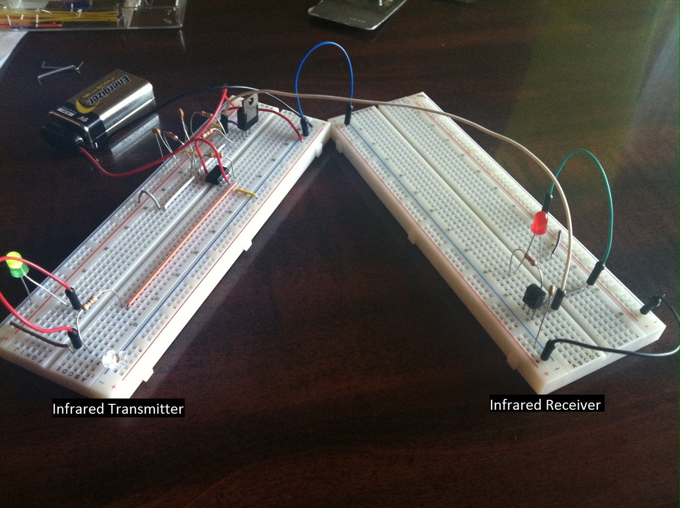
Step 4: Building the Transmitter

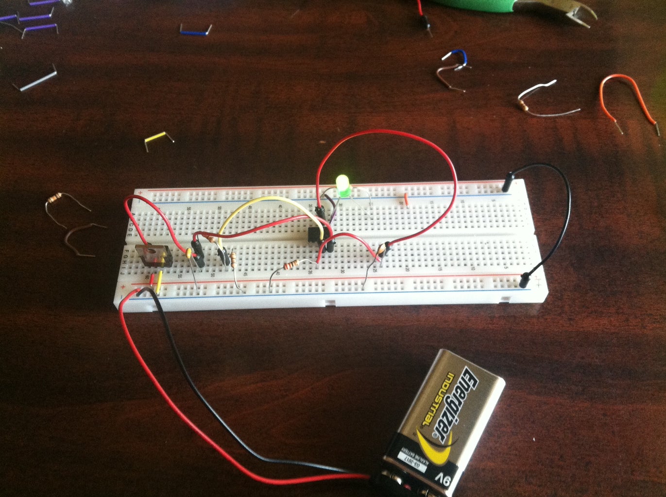
If it's difficult to follow what's going on in the circuit schematic in the previous step, then I've created a simulated version of what should be going on. Note, that you can design this circuit anyway you see fit. This is my first time using Zero to Breadboard Simulation, so things may be a bit crowded or not as optimal as I would have normally laid things out. I've also changed the notation of the capacitors, for those that may have been lost, 100 nF is equal to 0.1 uF.
The second image is an actual layout, it maybe hard to see what's exactly going on, but it will give you a general idea. I've also moved the 5V regulator to the other board to help in troubleshooting when I was building the circuit, so it is not showing in the Zero to Breadboard simulation.
NOTE! Be careful to follow pin diagrams for all parts!
It is important to note what all pins do what. If you plug something in incorrectly it WILL burn either the part itself up or create a dead spot in your board! Google the part number found on any of the parts listed in to see what they are if you are unsure or didn't keep any of the packaging that your parts came in.
Step 5: Building the Receiver


This is the more simple of the prototyping to do. This circuit contains only 5 components should be easy to place. Again, feel free to change your layout to make it more optimized. I played with several different layouts and ultimately decided that this would be best for me.
NOTE! Be careful to follow pin diagrams for all parts!
It is important to note what all pins do what. If you plug something in incorrectly it WILL burn either the part itself up or create a dead spot in your board! Google the part number found on any of the parts listed in to see what they are if you are unsure or didn't keep any of the packaging that your parts came in.
Step 6: Testing the Circuits

The final outcome depends on the parts that you chose. If you chose to stray from the ones listed, then you will have to recalculate what needs to be changed. The boards will also need to be adjusted so that they will properly see each other when you are pulling your car into the garage. Here is a demo of the project working.
Draw Backs and Improvements
This circuit is always on, therefore your battery will go dead and will need to be replaced at least once every two months. The goal later on will be to change the circuit so that it can detect ambient light and turn on when it is needed. However, if that change is made, then it will probably require an Arduino board implementation
Thanks and Credit
Original designs, schematics, and pictures featured in steps 1 and 3 and also the video for demo on this last step are from the projects original creator IRQ_EE. I found this project while working on an assignment for my English 314 technical writing course at Iowa State University College of Engineering. The assignment was to chose an instructable that was centered in our major and see if we could improve it's layout and design.


![Tim's Mechanical Spider Leg [LU9685-20CU]](https://content.instructables.com/FFB/5R4I/LVKZ6G6R/FFB5R4ILVKZ6G6R.png?auto=webp&crop=1.2%3A1&frame=1&width=306)


